front cover technical introduction: ibm zseries 800
TRANSCRIPT

ibm.com/redbooks
Technical Introduction:IBM zSeries 800
Bill OgdenLuiz Fadel
Mizuho KamataGrzegorz T. Kolecki
Shannon ProctorManfred Schwarz
Software: z/OS, z/OS.e, Linux
Planning and installation
Overview and FAQs
Front cover


International Technical Support Organization
Technical Introduction: IBM zSeries 800
February 2002
SG24-6515-00

© Copyright International Business Machines Corporation 2002. All rights reserved.Note to U.S Government Users - Documentation related to restricted rights - Use, duplication or disclosure is subject to restrictions setforth in GSA ADP Schedule Contract with IBM Corp.
First Edition (February 2002)
This edition applies to the initial announcement of the IBM zSeries 800 and the initial release of z/OS.e.
Comments may be addressed to:IBM Corporation, International Technical Support OrganizationDept. HYJ Mail Station P0992455 South RoadPoughkeepsie, NY 12601-5400
When you send information to IBM, you grant IBM a non-exclusive right to use or distribute the information in any way it believes appropriate without incurring any obligation to you.
Take Note! Before using this information and the product it supports, be sure to read the general information in “Special notices” on page 147.

Contents
Contents . . . . . . . . . . . . . . . . . . . . . . . . . . . . . . . . . . . . . . . . . . . . . . . . . . . . . . . . . . . . . . . . iii
Preface . . . . . . . . . . . . . . . . . . . . . . . . . . . . . . . . . . . . . . . . . . . . . . . . . . . . . . . . . . . . . . . . . viiThe team that wrote this redbook. . . . . . . . . . . . . . . . . . . . . . . . . . . . . . . . . . . . . . . . . . . . . . viiSpecial notice. . . . . . . . . . . . . . . . . . . . . . . . . . . . . . . . . . . . . . . . . . . . . . . . . . . . . . . . . . . . viiiIBM trademarks . . . . . . . . . . . . . . . . . . . . . . . . . . . . . . . . . . . . . . . . . . . . . . . . . . . . . . . . . . . ixComments welcome. . . . . . . . . . . . . . . . . . . . . . . . . . . . . . . . . . . . . . . . . . . . . . . . . . . . . . . . ix
Chapter 1. Overview . . . . . . . . . . . . . . . . . . . . . . . . . . . . . . . . . . . . . . . . . . . . . . . . . . . . . . 11.1 Hardware summary. . . . . . . . . . . . . . . . . . . . . . . . . . . . . . . . . . . . . . . . . . . . . . . . . . . . . 2
1.1.1 Differences . . . . . . . . . . . . . . . . . . . . . . . . . . . . . . . . . . . . . . . . . . . . . . . . . . . . . . . 31.1.2 Positioning . . . . . . . . . . . . . . . . . . . . . . . . . . . . . . . . . . . . . . . . . . . . . . . . . . . . . . . 4
1.2 IBM zSeries Offering for Linux . . . . . . . . . . . . . . . . . . . . . . . . . . . . . . . . . . . . . . . . . . . . 51.3 Software summary . . . . . . . . . . . . . . . . . . . . . . . . . . . . . . . . . . . . . . . . . . . . . . . . . . . . . 6
1.3.1 z/OS.e . . . . . . . . . . . . . . . . . . . . . . . . . . . . . . . . . . . . . . . . . . . . . . . . . . . . . . . . . . . 6
Chapter 2. Hardware . . . . . . . . . . . . . . . . . . . . . . . . . . . . . . . . . . . . . . . . . . . . . . . . . . . . . . 92.1 Processors . . . . . . . . . . . . . . . . . . . . . . . . . . . . . . . . . . . . . . . . . . . . . . . . . . . . . . . . . . 10
2.1.1 z/Architecture . . . . . . . . . . . . . . . . . . . . . . . . . . . . . . . . . . . . . . . . . . . . . . . . . . . . 102.1.2 Processor data flow . . . . . . . . . . . . . . . . . . . . . . . . . . . . . . . . . . . . . . . . . . . . . . . 112.1.3 The MCM . . . . . . . . . . . . . . . . . . . . . . . . . . . . . . . . . . . . . . . . . . . . . . . . . . . . . . . 122.1.4 The BPU-PK . . . . . . . . . . . . . . . . . . . . . . . . . . . . . . . . . . . . . . . . . . . . . . . . . . . . . 132.1.5 The system frame . . . . . . . . . . . . . . . . . . . . . . . . . . . . . . . . . . . . . . . . . . . . . . . . . 15
2.2 I/O cage. . . . . . . . . . . . . . . . . . . . . . . . . . . . . . . . . . . . . . . . . . . . . . . . . . . . . . . . . . . . . 162.2.1 I/O Summary. . . . . . . . . . . . . . . . . . . . . . . . . . . . . . . . . . . . . . . . . . . . . . . . . . . . . 18
2.3 System control . . . . . . . . . . . . . . . . . . . . . . . . . . . . . . . . . . . . . . . . . . . . . . . . . . . . . . . 192.3.1 Power design . . . . . . . . . . . . . . . . . . . . . . . . . . . . . . . . . . . . . . . . . . . . . . . . . . . . 20
2.4 z800 models . . . . . . . . . . . . . . . . . . . . . . . . . . . . . . . . . . . . . . . . . . . . . . . . . . . . . . . . . 212.4.1 Model upgrades . . . . . . . . . . . . . . . . . . . . . . . . . . . . . . . . . . . . . . . . . . . . . . . . . . 222.4.2 Concurrent upgrades . . . . . . . . . . . . . . . . . . . . . . . . . . . . . . . . . . . . . . . . . . . . . . 23
2.5 Basic z800 and z900 comparisons . . . . . . . . . . . . . . . . . . . . . . . . . . . . . . . . . . . . . . . . 232.6 CHPID mapping . . . . . . . . . . . . . . . . . . . . . . . . . . . . . . . . . . . . . . . . . . . . . . . . . . . . . . 24
Chapter 3. Software . . . . . . . . . . . . . . . . . . . . . . . . . . . . . . . . . . . . . . . . . . . . . . . . . . . . . 273.1 z/OS.e . . . . . . . . . . . . . . . . . . . . . . . . . . . . . . . . . . . . . . . . . . . . . . . . . . . . . . . . . . . . . . 28
3.1.1 Specific limitations . . . . . . . . . . . . . . . . . . . . . . . . . . . . . . . . . . . . . . . . . . . . . . . . 283.1.2 Pricing model . . . . . . . . . . . . . . . . . . . . . . . . . . . . . . . . . . . . . . . . . . . . . . . . . . . . 293.1.3 Middleware pricing methodology. . . . . . . . . . . . . . . . . . . . . . . . . . . . . . . . . . . . . . 33
3.2 Customized Offerings Driver . . . . . . . . . . . . . . . . . . . . . . . . . . . . . . . . . . . . . . . . . . . . . 343.3 z/OS . . . . . . . . . . . . . . . . . . . . . . . . . . . . . . . . . . . . . . . . . . . . . . . . . . . . . . . . . . . . . . . 363.4 VM/ESA and z/VM . . . . . . . . . . . . . . . . . . . . . . . . . . . . . . . . . . . . . . . . . . . . . . . . . . . . 38
3.4.1 HiperSockets and VM . . . . . . . . . . . . . . . . . . . . . . . . . . . . . . . . . . . . . . . . . . . . . . 383.4.2 z/VM System Administration Facility . . . . . . . . . . . . . . . . . . . . . . . . . . . . . . . . . . . 393.4.3 VM in an IFL . . . . . . . . . . . . . . . . . . . . . . . . . . . . . . . . . . . . . . . . . . . . . . . . . . . . . 403.4.4 VM cryptographic support for Linux images . . . . . . . . . . . . . . . . . . . . . . . . . . . . . 40
3.5 Linux . . . . . . . . . . . . . . . . . . . . . . . . . . . . . . . . . . . . . . . . . . . . . . . . . . . . . . . . . . . . . . . 403.5.1 32-bit and 64-bit Linux . . . . . . . . . . . . . . . . . . . . . . . . . . . . . . . . . . . . . . . . . . . . . 413.5.2 Linux distributions . . . . . . . . . . . . . . . . . . . . . . . . . . . . . . . . . . . . . . . . . . . . . . . . . 423.5.3 Linux installation . . . . . . . . . . . . . . . . . . . . . . . . . . . . . . . . . . . . . . . . . . . . . . . . . . 43
© Copyright IBM Corp. 2002 iii
3.5.4 Setting up a HiperSockets LAN for Linux . . . . . . . . . . . . . . . . . . . . . . . . . . . . . . . 47
Chapter 4. Discussion topics . . . . . . . . . . . . . . . . . . . . . . . . . . . . . . . . . . . . . . . . . . . . . . 494.1 Parallel channel planning . . . . . . . . . . . . . . . . . . . . . . . . . . . . . . . . . . . . . . . . . . . . . . . 49
4.1.1 Byte multiplexor . . . . . . . . . . . . . . . . . . . . . . . . . . . . . . . . . . . . . . . . . . . . . . . . . . 504.2 ESCON channels . . . . . . . . . . . . . . . . . . . . . . . . . . . . . . . . . . . . . . . . . . . . . . . . . . . . . 50
4.2.1 Consideration for ES conversion channels . . . . . . . . . . . . . . . . . . . . . . . . . . . . . . 514.3 FICON Express . . . . . . . . . . . . . . . . . . . . . . . . . . . . . . . . . . . . . . . . . . . . . . . . . . . . . . . 51
4.3.1 FICON CTC . . . . . . . . . . . . . . . . . . . . . . . . . . . . . . . . . . . . . . . . . . . . . . . . . . . . . 544.4 OSA-Express adapters . . . . . . . . . . . . . . . . . . . . . . . . . . . . . . . . . . . . . . . . . . . . . . . . . 56
4.4.1 Fast Ethernet . . . . . . . . . . . . . . . . . . . . . . . . . . . . . . . . . . . . . . . . . . . . . . . . . . . . 574.4.2 Gigabit Ethernet . . . . . . . . . . . . . . . . . . . . . . . . . . . . . . . . . . . . . . . . . . . . . . . . . . 584.4.3 High Speed Token Ring . . . . . . . . . . . . . . . . . . . . . . . . . . . . . . . . . . . . . . . . . . . . 594.4.4 155 ATM . . . . . . . . . . . . . . . . . . . . . . . . . . . . . . . . . . . . . . . . . . . . . . . . . . . . . . . . 604.4.5 Emulated I/O to OSA migration. . . . . . . . . . . . . . . . . . . . . . . . . . . . . . . . . . . . . . . 61
4.5 MCL updates. . . . . . . . . . . . . . . . . . . . . . . . . . . . . . . . . . . . . . . . . . . . . . . . . . . . . . . . . 614.5.1 Running Single Step Internal Code Changes as a scheduled operation . . . . . . . 64
4.6 IOCDS. . . . . . . . . . . . . . . . . . . . . . . . . . . . . . . . . . . . . . . . . . . . . . . . . . . . . . . . . . . . . . 644.6.1 IOCP statements. . . . . . . . . . . . . . . . . . . . . . . . . . . . . . . . . . . . . . . . . . . . . . . . . . 654.6.2 Channel definitions in the IOCP statement . . . . . . . . . . . . . . . . . . . . . . . . . . . . . . 664.6.3 Building an IOCDS from an IOCP source input file. . . . . . . . . . . . . . . . . . . . . . . . 67
4.7 IBM 2074 setup . . . . . . . . . . . . . . . . . . . . . . . . . . . . . . . . . . . . . . . . . . . . . . . . . . . . . . . 694.8 Integrated Facility for Linux . . . . . . . . . . . . . . . . . . . . . . . . . . . . . . . . . . . . . . . . . . . . . . 71
4.8.1 Adding an IFL . . . . . . . . . . . . . . . . . . . . . . . . . . . . . . . . . . . . . . . . . . . . . . . . . . . . 734.9 LPAR setup and examples . . . . . . . . . . . . . . . . . . . . . . . . . . . . . . . . . . . . . . . . . . . . . . 744.10 HiperSockets. . . . . . . . . . . . . . . . . . . . . . . . . . . . . . . . . . . . . . . . . . . . . . . . . . . . . . . . 77
4.10.1 Defining HiperSockets in IOCP statements . . . . . . . . . . . . . . . . . . . . . . . . . . . . 784.10.2 Defining HiperSockets in the z/OS TCP/IP profile . . . . . . . . . . . . . . . . . . . . . . . 79
4.11 Physical planning notes . . . . . . . . . . . . . . . . . . . . . . . . . . . . . . . . . . . . . . . . . . . . . . . 804.11.1 Emergency power . . . . . . . . . . . . . . . . . . . . . . . . . . . . . . . . . . . . . . . . . . . . . . . . 814.11.2 Cable ordering . . . . . . . . . . . . . . . . . . . . . . . . . . . . . . . . . . . . . . . . . . . . . . . . . . 81
4.12 Fiber cables and connectors . . . . . . . . . . . . . . . . . . . . . . . . . . . . . . . . . . . . . . . . . . . . 834.12.1 MCP cables. . . . . . . . . . . . . . . . . . . . . . . . . . . . . . . . . . . . . . . . . . . . . . . . . . . . . 844.12.2 Replacement cables . . . . . . . . . . . . . . . . . . . . . . . . . . . . . . . . . . . . . . . . . . . . . . 84
4.13 Resource Link . . . . . . . . . . . . . . . . . . . . . . . . . . . . . . . . . . . . . . . . . . . . . . . . . . . . . . . 854.13.1 Accessing Resource Link . . . . . . . . . . . . . . . . . . . . . . . . . . . . . . . . . . . . . . . . . . 854.13.2 Resource Link menu . . . . . . . . . . . . . . . . . . . . . . . . . . . . . . . . . . . . . . . . . . . . . . 864.13.3 Tools . . . . . . . . . . . . . . . . . . . . . . . . . . . . . . . . . . . . . . . . . . . . . . . . . . . . . . . . . . 87
4.14 Crypto overview . . . . . . . . . . . . . . . . . . . . . . . . . . . . . . . . . . . . . . . . . . . . . . . . . . . . . 884.14.1 PCICC cards . . . . . . . . . . . . . . . . . . . . . . . . . . . . . . . . . . . . . . . . . . . . . . . . . . . . 904.14.2 PCICA cards . . . . . . . . . . . . . . . . . . . . . . . . . . . . . . . . . . . . . . . . . . . . . . . . . . . . 924.14.3 Practical mix . . . . . . . . . . . . . . . . . . . . . . . . . . . . . . . . . . . . . . . . . . . . . . . . . . . . 924.14.4 RMF for crypto . . . . . . . . . . . . . . . . . . . . . . . . . . . . . . . . . . . . . . . . . . . . . . . . . . 924.14.5 Cryptographic performance planning for SSL. . . . . . . . . . . . . . . . . . . . . . . . . . . 93
4.15 Sysplex Timer connection . . . . . . . . . . . . . . . . . . . . . . . . . . . . . . . . . . . . . . . . . . . . . . 934.16 Optica planning . . . . . . . . . . . . . . . . . . . . . . . . . . . . . . . . . . . . . . . . . . . . . . . . . . . . . . 944.17 Upgrade to 2064 . . . . . . . . . . . . . . . . . . . . . . . . . . . . . . . . . . . . . . . . . . . . . . . . . . . . . 974.18 Support Element and Hardware Management Consoles . . . . . . . . . . . . . . . . . . . . . . 98
4.18.1 Support Element . . . . . . . . . . . . . . . . . . . . . . . . . . . . . . . . . . . . . . . . . . . . . . . . . 984.18.2 Hardware Management Console . . . . . . . . . . . . . . . . . . . . . . . . . . . . . . . . . . . . 994.18.3 SE and HMC connectivity . . . . . . . . . . . . . . . . . . . . . . . . . . . . . . . . . . . . . . . . . 1004.18.4 HMC levels . . . . . . . . . . . . . . . . . . . . . . . . . . . . . . . . . . . . . . . . . . . . . . . . . . . . 1034.18.5 Practical management of SE and HMC . . . . . . . . . . . . . . . . . . . . . . . . . . . . . . 103
iv Technical Introduction: IBM zSeries 800
4.19 Remote model upgrades: CUoD and CBU . . . . . . . . . . . . . . . . . . . . . . . . . . . . . . . . 1044.19.1 Capacity upgrade on demand (CUoD) . . . . . . . . . . . . . . . . . . . . . . . . . . . . . . . 1044.19.2 Capacity backup (CBU). . . . . . . . . . . . . . . . . . . . . . . . . . . . . . . . . . . . . . . . . . . 104
4.20 Open FCP . . . . . . . . . . . . . . . . . . . . . . . . . . . . . . . . . . . . . . . . . . . . . . . . . . . . . . . . . 1074.21 Processor cache discussion . . . . . . . . . . . . . . . . . . . . . . . . . . . . . . . . . . . . . . . . . . . 1074.22 Integrated Coupling Facility. . . . . . . . . . . . . . . . . . . . . . . . . . . . . . . . . . . . . . . . . . . . 108
4.22.1 CF links . . . . . . . . . . . . . . . . . . . . . . . . . . . . . . . . . . . . . . . . . . . . . . . . . . . . . . . 1104.22.2 Peer mode . . . . . . . . . . . . . . . . . . . . . . . . . . . . . . . . . . . . . . . . . . . . . . . . . . . . 1114.22.3 Internal Coupling channels . . . . . . . . . . . . . . . . . . . . . . . . . . . . . . . . . . . . . . . . 113
4.23 Spare PUs. . . . . . . . . . . . . . . . . . . . . . . . . . . . . . . . . . . . . . . . . . . . . . . . . . . . . . . . . 1144.24 Intelligent Resource Director . . . . . . . . . . . . . . . . . . . . . . . . . . . . . . . . . . . . . . . . . . . 114
4.24.1 IRD - LPAR CPU Management. . . . . . . . . . . . . . . . . . . . . . . . . . . . . . . . . . . . . 1164.24.2 IRD - Dynamic Channel-path management . . . . . . . . . . . . . . . . . . . . . . . . . . . 1174.24.3 IRD - Channel Subsystem Priority Queuing . . . . . . . . . . . . . . . . . . . . . . . . . . . 1184.24.4 IRD - non-z/OS partitions . . . . . . . . . . . . . . . . . . . . . . . . . . . . . . . . . . . . . . . . . 1194.24.5 Requirements for IRD functions . . . . . . . . . . . . . . . . . . . . . . . . . . . . . . . . . . . . 1194.24.6 IRD setup tips for z800 . . . . . . . . . . . . . . . . . . . . . . . . . . . . . . . . . . . . . . . . . . . 1204.24.7 Operating considerations . . . . . . . . . . . . . . . . . . . . . . . . . . . . . . . . . . . . . . . . . 124
4.25 Hardware data compression . . . . . . . . . . . . . . . . . . . . . . . . . . . . . . . . . . . . . . . . . . . 125
Chapter 5. Frequently asked questions . . . . . . . . . . . . . . . . . . . . . . . . . . . . . . . . . . . . 127
Appendix A. Listings . . . . . . . . . . . . . . . . . . . . . . . . . . . . . . . . . . . . . . . . . . . . . . . . . . . 137IOCDS for COD . . . . . . . . . . . . . . . . . . . . . . . . . . . . . . . . . . . . . . . . . . . . . . . . . . . . . . . . . 138IOCDS for Linux (two partitions) . . . . . . . . . . . . . . . . . . . . . . . . . . . . . . . . . . . . . . . . . . . . 139IOCDS for z/OS, z/OS.e and Linux (LPARs) . . . . . . . . . . . . . . . . . . . . . . . . . . . . . . . . . . . 140
Appendix B. Preliminary performance . . . . . . . . . . . . . . . . . . . . . . . . . . . . . . . . . . . . . 145
Special notices . . . . . . . . . . . . . . . . . . . . . . . . . . . . . . . . . . . . . . . . . . . . . . . . . . . . . . . . . 147
Related publications . . . . . . . . . . . . . . . . . . . . . . . . . . . . . . . . . . . . . . . . . . . . . . . . . . . . 149IBM Redbooks . . . . . . . . . . . . . . . . . . . . . . . . . . . . . . . . . . . . . . . . . . . . . . . . . . . . . . . . . . 149
Other resources . . . . . . . . . . . . . . . . . . . . . . . . . . . . . . . . . . . . . . . . . . . . . . . . . . . . . . 149Referenced Web sites . . . . . . . . . . . . . . . . . . . . . . . . . . . . . . . . . . . . . . . . . . . . . . . . . . . . 149How to get IBM Redbooks . . . . . . . . . . . . . . . . . . . . . . . . . . . . . . . . . . . . . . . . . . . . . . . . . 149
IBM Redbooks collections. . . . . . . . . . . . . . . . . . . . . . . . . . . . . . . . . . . . . . . . . . . . . . . 150
Index . . . . . . . . . . . . . . . . . . . . . . . . . . . . . . . . . . . . . . . . . . . . . . . . . . . . . . . . . . . . . . . . . 151
Contents v

vi Technical Introduction: IBM zSeries 800

Preface
This IBM Redbook describes the IBM z800 family of systems. These are IBM machine type 2066 systems, with a number of different models. The z800 systems are smaller but quite similar to the well accepted z900 systems, often known by their development name as the “Freeway” series. Consequently, the z800 machines are sometimes characterized as “baby Freeways.” This is close, but not quite accurate. The z800 machines offer a lower entry point, in both price and performance, than the z900s, but have a few characteristics that differ somewhat from the larger systems.
z/OS.e is a special packaging of z/OS that is unique to the z800 machines. It is a reduced function z/OS with a significantly lower price than full z/OS. z/OS.e is targeted at new workloads based on e-business constructs, using C, C++, and Java languages and working with WebSphere, DB2, and similar middleware. Traditional workloads cannot be run with z/OS.e.
This book is for readers with a general S/390 and z/OS background; common terms and acronyms are used without introduction. Also included is a limited amount of introductory material for Linux users who are not familiar with S/390 platforms. The goal of the book is to provide a technical introduction to the z800.
The team that wrote this redbookThis redbook was produced by a team of specialists from around the world working at the International Technical Support Organization, Poughkeepsie Center.
Bill Ogden is a retired IBM Senior Technical Staff Member, still working part-time on favorite projects at the International Technical Support Organization, Poughkeepsie Center. He specializes in entry-level OS/390 and z/OS systems, writes extensively, and teaches ITSO workshops relating to these areas. Bill has been with the ITSO since 1978. Many of his projects for the last several years have been related to IBM’s S/390 Partners in Development organization.
Luiz Fadel is a certified Consulting IT Specialist from Sao Paulo, Brazil. He has more than 30 years of experience with MVS and OS/390. He has written extensively on OS/390.
Mizuho Kamata is an IT Specialist, in the area of zSeries, S/390 processor hardware and z/OS, and OS/390 in IBM Japan. He has 12 years of experience with IBM in those areas, especially in configuration and performance management. He also writes and teaches in his country.
Grzegorz T. Kolecki works for IBM Poland, located in Warsaw, Poland. He has had 11 years of experience in ES/9000, S/390 and zSeries systems, working first as a Customer Engineer in Software, then as a Systems Engineer, and finally as a Senior Sales Specialist. His main areas of interest are processor hardware, OS/390 and z/OS operating systems, as well as storage subsystems.
Shannon Proctor is a Field Technical Sales Specialist from the Northeast Region. She specializes in zSeries hardware and has been focusing on new technologies including the z900, z/OS and Linux.
© Copyright IBM Corp. 2002 vii
Manfred Schwarz is an IT Specialist, working in the EMEA Central Region Hardware Support zSeries, located in Mainz, Germany. Manfred has been with IBM since 1979 and has 15 years of experience in the ES/9000, S/390 and zSeries fields. He provides S/390 and zSeries HW System Support and has additional skills in HW Crypto Support.
Thanks to the following people for their contributions to this project:
Krisanne Wallner and Bob Nasser, IBM Poughkeepsie, who helped coordinate access to the material described in this redbook, and who provided an early z800 processor for this work. Many other developers—far too many to list—work with Krisanne and Bob and many contributed information for this redbook.
Darelle Gent, IBM Poughkeepsie, helped us through much of the z800 planning process.
A group from S/390 Product Engineering helped us learn about our hew hardware. This group included Warren Peterson, Dan Smith, Ray Hafer, Scott Korfhage, and Glen Poulsen.
Betty Hibler, IBM Poughkeepsie, helped coordinate early use of z/OS.e. Betty works with a large team and many people contributed to the z/OS.e effort. In particular, we recognize Randy Stelman, who created the basic concepts behind z/OS.e and helped turn an idea into a product.
Carlos Ordonez, IBM Poughkeepsie, provided invaluable help with the Linux installation.
Special noticeThis publication is intended to provide a broad overview of the hardware aspects of the IBM 2066 processor and the new packaging of z/OS that results in the z/OS.e offering.
viii Technical Introduction: IBM zSeries 800

IBM trademarksThe following terms are trademarks of the International Business Machines Corporation in the United States and/or other countries:
Comments welcomeYour comments are important to us!
We want our IBM Redbooks to be as helpful as possible. Send us your comments about this or other Redbooks in one of the following ways:
� Use the online Contact us review redbook form found at:
ibm.com/redbooks
� Send your comments in an Internet note to:
� Mail your comments to the address on page ii.
e (logo)® IBM®APPN®BatchPipes®CICS®Cross-Site®CUA®DB2®DFS™DFSMS/MVS®DFSMSdfp™DFSMSdss™DFSMShsm™Enterprise Storage Server™ES/9000®ESCON®FICON™GDDM®GDPS™Geographically Dispersed Parallel Sysplex™IMS™Language Environment®Manage. Anything. Anywhere®MQSeries®Multiprise®MVS™Netfinity®NetView®OS/2®OS/390®Parallel Sysplex®
Redbooks™Redbooks Logo Perform™Planet Tivoli®PowerPC®PR/SM™PR/SM™RACF®RAMAC®Resource Link™RETAIN®RMF™S/370™S/390®SecureWay®SP™Sysplex Timer®TCS®ThinkPad®Tivoli®Tivoli Enterprise™TME®VM/ESA®VSE/ESA™VTAM®WebSphere®z/Architecture™z/OS™z/VM™zSeries™3890™Notes®
Preface ix

x Technical Introduction: IBM zSeries 800

Chapter 1. Overview
The IBM zSeries 800 family is the defining element of IBM midrange mainframe servers. These systems complement the high-end zSeries 900 systems, providing a smooth path from 80 MIPS (the smallest generally available zSeries 800) to the largest zSeries 900 system. This chapter provides a brief summary of these systems, while later chapters explore selected details in more depth.
A special packaging of z/OS is available only for the zSeries 800 machines. This is a packaging, not a new operating system, and is known as z/OS.e. The intention is to provide a limited portion of z/OS, at a greatly reduced cost, that is geared toward new workloads.
1
© Copyright IBM Corp. 2002 1

1.1 Hardware summaryThe following is a quick summary of the zSeries 800 processor family:
� Processors
– The system contains five processing units (PUs). These provide z800 models with one SAP1 (always) and one to four S/390 CPs. Alternately, the PUs can be used for IFLs (for Linux) or ICFs (for Coupling Facilities).
– “Sub-uni” models are available with less capacity than a single “full” uniprocessor.
– Models with MSUs ranging from 13 to 108 are available.2
• A smaller model is available only in Japan. This redbook is not intended to cover this model.
– All models are full members of the 64-bit processing architecture introduced by the zSeries 900 family.
� Memory
– 8 to 32 GB, in units of 8 GB, is available.
� I/O capability
– One cage for I/O cards, with 16 slots in the cage, is used.
– Many, but not all, of the I/O cards used with the zSeries 900 family are used with the z800.
– Up to 240 ESCON channels are available, if all the I/O slots are used for ESCON channels.
– Several types of OSA-Express cards are available.
� Packaging
– A single rack is used, generally matching the zSeries 900 racks in appearance.
– A raised-floor environment is expected.
– Dual power feeds are used, with input from 200 to 240 volts.
– A maximum of 3850 watts is needed, with about 16,000 BTUs cooling required.
� Compatibility
– The zSeries 800 is software-compatible with the zSeries 900 machines. All currently supported operating systems (OS/390, z/OS, VM/ESA, VSE/ESA, TPF, Linux for S/390, and Linux for z/Architecture) can be used.
� Parallel Sysplex
– The zSeries 800 can participate fully in a Parallel Sysplex environment.
� Specialized LPARs and PUs
– PUs can be dedicated to IFL functions (Linux or Linux under VM)
– PUs can be dedicated to ICF functions (Coupling Facility code).
1 A System Assist Processor (SAP) is a processor (PU) that runs internal microcode, primarily to control the I/O subsystem.2 MSUs are intended to be a more meaningful capacity metric than simple MIPS. MSU stands for Million Service Units per hour. Serviceunits were one of the parameters used to control the System Resource Manager (SRM) in earlier MVS systems. As used today, MSUsgenerally reflect only processing power; earlier SU definitions also involved I/O and main storage usage.
2 Technical Introduction: IBM zSeries 800
1.1.1 DifferencesThe zSeries 800 is typically compared with the zSeries 900 (at the high end) and with the Multiprise 3000 (at the low end). Key differences are summarized here.
� General differences from both MP3000 and z900 machines:
– There are no parallel channels available with the zSeries 800. However, converter boxes may be used to connect customer-owner parallel channel control units to zSeries 800 ESCON channels. See “Parallel channel planning” on page 49 for more discussion.
– No internal battery feature (IBF) is available. See “Physical planning notes” on page 80 for more discussion.
� z900 differences:
– OSA-2 adapters (including FDDI adapters) cannot be used with the zSeries 800.
– Only a single frame is used for the zSeries 800 models. Expansion to a second frame is not possible. I/O connectivity is limited to the combinations of cards that can be used in the 16 slots of the I/O cage.
– The Power Save function, available on earlier z900 machines, is not available.3 This function has been withdrawn for the z900; the z800 and current z900 systems are equivalent in this respect.
– A spare processor is always available on a fully-configured z900, while a fully configured z800 will not have a spare processor.
– ICB-2 connections (to Coupling Facilities) are not available; ISC-3 and/or ICB-3 links can be used instead.
– Readers familiar with the z900 series should note that the Compatibility I/O Cage is not available with the z800 machines. I/O cards requiring this I/O cage may not be used.
– There is no internal refrigeration; fan-assisted air cooling is used.
– The cable ordering process is different. See “Cable ordering” on page 81 for more details.
– The (optional) cryptographic coprocessors are single-chip modules that plug into the system board on the z800; they can be changed without replacing the MCM. On the z900, the cryptographic coprocessors are also plugged into the system board, but they are always present. (A appropriate feature code is needed to activate them.)
– The traditional ESCON-type ETR connectors are used on a z800 to connect to an external Sysplex clock, while a z900 uses the MT-RJ type of connector.
� MP3000 differences:
– No internal disk drives or tape drives are available with the zSeries 800. This difference is especially relevant for current Multiprise customers.
– No emulated I/O, like that of the Multiprise 3000, is available.
– The Support Elements (SEs) are similar to that of the zSeries 900, and are unlike that of the Multiprise 3000. In particular, the SEs are not suitable for routine use as operating system operator consoles or user terminals.
– A Hardware Management Console (HMC) is required, unlike a Multiprise 3000 where it is optional. See “Support Element and Hardware Management Consoles” on page 98 for more discussion.
� zSeries differences with other S/390 machines:
3 This was a z900 feature that keeps power available to system memory (and thus preserves the memory contents) when other power isremoved.
Chapter 1. Overview 3

– The ICMF function is not available. However, the ICF function is available. (These refer to two different ways to run a Coupling Facility (CF) instance in a portion of the machine.) See “Integrated Coupling Facility” on page 108 for more details.
– The Asynchronous Data Mover facility is not available.
1.1.2 PositioningFigure 1-1 may help position the z800 machines against other current systems, in terms of processing power. Note that the performance scale, in arbitrary units, is approximately logarithmic. The largest z800 is more than three times the performance of the largest MP3000, in purely processor terms. In other areas, the z800 and z900 systems are quite similar and processor performance offers a reasonable comparison basis.
Of course, processor speed is only one way to compare systems. Both the “z” families offer greater channel connectivity than the Multiprise 3000 family and vastly greater channel connectivity than any of the EFS systems (which are described in the next paragraph). The MP3000 offers 31-bit processing, while the other families shown in the figure offer 64-bit processing.4 The MP3000 will not be replaced with a 64-bit version. In part, the z800 series can be considered a replacement for the MP3000.
The EFS machines, if you have not encountered them before, provide entry-level S/390 systems. The “EFS” name means Enabled For S/390. All these systems are based on S/390 emulation, running on Intel processors. EFS systems are obtained through business partners and are not directly sold by IBM. The EFS family of solutions is developing in parallel with IBM’s midrange (z800) and high-end (z900) systems. At the time of writing, IBM has not fully articulated its future involvement with EFS systems. Also, at the time of writing, EFS provides only 31-bit operation. Fundamental Software, Incorporated (of Fremont, California)—the developer of the FLEX-ES emulation software used by EFS systems—has indicated that they plan 64-bit operation in the future.
4 EFS support for 64-bit z/Architecture is a future goal of these systems, and was not available at the time of writing.
4 Technical Introduction: IBM zSeries 800

Figure 1-1 General positioning of z800 Series, with arbitrary performance units
Confining our observations to 64-bit systems only (and thus excluding the MP3000), there is a considerable gap between the largest EFS machine5 and the smallest z800 machine. The processing performance of EFS machines has considerable potential for growth, but the channel connectivity is expected to remain far behind the z800 family. (The EFS systems have internal DASD, with excellent performance, and this must be taken into account when comparing systems. For information about EFS systems see the redbook S/390 Partners in Development: Netfinity Enabled For S/390, SG24-6501and any later redbooks in that series.)
The ELS notation, for the smallest EFS system, refers to special software packaging and pricing originally for P/390 systems. ELS pricing is not available for z800 systems.
1.2 IBM zSeries Offering for LinuxShortly before the general purpose z800 was announced, IBM announced a zSeries Offering for Linux involving the z800 machines. This Linux offering includes the same processor that is described in this redbook. Very briefly, the Linux offering package includes:
� A z800 model 0LF, with one to four IFL processors– The exact machine type is 2066-0FL. Feature codes 3605, 3606, 3607, and 3608 are
used to specify one to four IFL PUs.� Appropriate I/O adapters for Linux
– Two OSA-Express cards are included in the standard offering. The customer may select which cards he wants.
– Two FICON-Express cards are included in the standard offering.– Thirty ESCON ports are included in the standard offering.
10
20
50
100
200
500
1000
EFS MP3000 z800 z900
Pro
cess
or
Pow
er
H30
H50 H
70 2
-way
ELS
0A1 0B
1 0C1 00
1
0A2
2-w
ay
002
2-w
ay
003
3-w
ay
004
4-w
ay
1-w
ay
16-w
ay
64-bit 32-bit32 bit nowfuture 64 bit
5 Assuming that 64-bit EFS operation is delivered in the future.
Chapter 1. Overview 5
– Most additional z800 I/O features may be ordered.� Standard memory sizes
– 8 GB is standard if one or two IFLs are ordered.– 16 GB is standard when three or four IFLs are ordered.– Normal z800 memory upgrades (in 8 GB increments to a maximum of 32 GB) may be
ordered.� An HMC, with display and hub or MAU, is included.� z/VM version 4� Three years of hardware support (one year warranty plus two years maintenance) are
included.� Three years of z/VM subscription and support.� A financing option is available.� Services options are available.
The z800 processor and I/O features announced with the Linux offering includes only those that are meaningful in a Linux-only environment. Also, the terms of the offering cover the use of z/VM version 4 only; earlier releases may not be used. Since IFLs are involved, you cannot use the system in basic mode (without LPARs). You can run Linux directly (in one to fifteen LPARs) without using z/VM if you wish, but the z/VM license is a standard part of the offering.
Since the technical details of the z800 are the same for the general purpose models and the Linux offering, we will not address the Linux offering separately in the remainder of this redbook.6
1.3 Software summaryThe z800 family is fully compatible with all software used by the z900 family. In addition, a special packaging of z/OS is available solely for the z800 family. This is the z/OS.e offering. It is important to note that z/OS.e is an option; normal, “full” z/OS can also be used and is expected to be the dominant operating system for the z800 family.
The z800 systems may be used with:
� OS/390 Version 2 Releases 8 and later7
� z/OS, any release (this includes the new z/OS.e packaging of z/OS)� VM/ESA release 2.4� z/VM release 3.1.0, 4.1.0, 4.2.0, and later� VSE/ESA Version 2 Releases 4, 5, and 6 and later� Linux for S/390 � Linux for z/Architecture � TPF level 4.1 and later
1.3.1 z/OS.ez/OS.e is a reduced z/OS at a much reduced price. The facilities included in z/OS.e are those needed for new workload applications. This term is intended to cover Java, C, C++, DB/2, WAS and similar elements needed for e-business types of workloads. Not included are facilities for COBOL, Fortran, PL/1 development, CICS, IMS, general TSO, and similar traditional workload elements.
The exclusion of traditional workload facilities is done in several ways:
6 One minor technical difference is that the cryptographic coprocessors are not prerequisites for cryptographic PCICA cards on theLinux-only model.7 Support from OS/390 release 2.6 is available in Japan.
6 Technical Introduction: IBM zSeries 800

� Some elements and products are not orderable and are not shipped with z/OS.e.� Some elements are present in the shipped system, but disabled by various means.� Some elements are excluded from use by the license terms and conditions for z/OS.e.
z/OS.e is discussed in more detail in “z/OS.e” on page 28. Note that z/OS.e is not a new operating system. It is simply a packaging of z/OS with some elements removed or otherwise disabled. The functional elements are binary equivalents to the same elements in a full z/OS package. With some minor exceptions, all the documentation and service for z/OS also applies to z/OS.e.
Determining what is a new workload versus what is a traditional workload, for the purposes of using z/OS.e, is not always obvious. The Terms and Conditions license agreement for z/OS.e is the primary reference for such questions.
Chapter 1. Overview 7

8 Technical Introduction: IBM zSeries 800

Chapter 2. Hardware
This chapter describes the basic processor hardware in a z800 system. More extended discussions of specific elements are found in “Discussion topics” on page 49. Most of the information in this chapter is not required to select or use a z800 system, and is provided simply as general information for the technically curious.
2
© Copyright IBM Corp. 2002 9

2.1 ProcessorsThe core elements of any computer are the processing units (PUs). All z800 machines have five PUs. The same chips are used in the z800 and z900. These contain the z/Architecture logic and functions and implement the architectural extensions of S/390 ESA architecture.
We discuss a PU as a single processor. As implemented in the z800 and z900 machines, each PU actually has dual internal instruction processors. Instructions are executed by both internal processors, in parallel, and the results compared.1 If the results do not match, an instruction retry process is performed.2 This is all done automatically, by the PU hardware, and is not visible to the operating system. The normal result of the dual processors in a PU is the execution of a single instruction stream. Thus we normally refer to a PU as a single processor and ignore the fact that there are really two parallel processors inside each PU.
Each of the five PUs can be used in one of these ways:
� A CP, used by the operating system for executing customer work.� A System Assistance Processor (SAP). There is always one, and only one, SAP in a z800
system.� A spare. This is a PU that is not enabled for any purpose in a particular z800 system. The
system will use this to replace a failing processor, if needed. If all four PUs (plus a SAP) are enabled, then there are no spare PUs. Spare PUs may be used for various upgrade options such as Capacity Backup (CBU) and Customer Upgrade on Demand (CUoD).
� An Integrated Linux Facility (IFL) PU. This is restricted to running Linux or Linux under VM.
� An Integrated Coupling Facility (ICF) PU. This is used to run the Coupling Facility function for use in a Parallel Sysplex environment.
An IFL is a processor reserved for Linux (or Linux under VM). The significance is that it cannot be used to run other operating systems and its existence is not reflected in the system model number, MIPS rating, or other power ratings. The system model (or MIPS, or other power rating method) has significant implications for software costs. Adding an IFL does not affect these costs, permitting the use of Linux without impacting other software costs.
An ICF is used only to run the Coupling Facility licensed code. It cannot be used to run normal operating systems. It is similar to an IFL in that its existence does not change the system model number (or MIPS rating) and does not impact software costs for system.
The use of IFLs and/or ICFs requires the use of LPARs. If neither of these are used, a z800 system can run in basic mode (no LPARs). Note, however, that use of the new z/OS.e operating system package requires the use of LPARs.
2.1.1 z/Architecturez/Architecture is the architecture implemented in the z900 series, with an identical implementation for the z800 series. It is sometimes characterized as the 64-bit architecture, although it also includes a number of additions to the base instruction set. As a starting point, it includes all the earlier extensions to ESA architecture, such as binary floating point.
A large number of new instructions are included for 64-bit operation. These are detailed in z/Architecture Principles of Operation, SA22-7832. The new facilities include:
� 64-bit general registers� 64-bit integer instructions, generally paralleling the older 32-bit integer instructions
1 The actual dual processing is a little more complex than described here. The details are not documented by IBM.2 If this fails, then more elaborate recovery functions are invoked to remove the failing PU and transparently shift its workload to another PU.
10 Technical Introduction: IBM zSeries 800

� 32-to-64-bit integer instructions for working with mixed operands� 64-bit address generation� 64-bit control registers� 64-bit addresses for Indirect Address words used with channel programs� 64-bit addresses for use with queued I/O control (QDIO), currently used with the OSA
adapter for Gigabit Ethernet� 64-bit ISC3 and ICB3 addressing for Coupling Facility communication� 64-bit operation for SIE instruction functions� 64-bit addresses and operands for crypto functions (both coprocessor and PCI
implementations)
2.1.2 Processor data flowThe sketch in Figure 2-1 on page 12 illustrates the general data flow of a z800 system. (As a side note, all of the elements in this sketch except the I/O cage are mounted in a physical module known as the Base Processor Unit - Package (BPU-PK), which is shown in the frame layout in Figure 2-4 on page 15.)
A number of characteristics are reflected in the figure:
� Five PUs are always present in a z800 system. There is no way to increase or decrease this number. Several of the PUs may not be activated, depending on the z800 model purchased. Various uses for PUs are discussed later. The basic PU cycle time is 1.6 ns.
� L1 cache is integrated with each PU, and consists of 256 KB for an instruction cache and a different 256 KB for a data cache. This is known as a split cache and is discussed in more detail in 4.21, “Processor cache discussion” on page 107.
� L2 cache is 8 MB, shared across all PUs.� Four memory sizes are available, based on units of 8 GB.� The memory bus adapter (MBA) provides six fast paths (1 GB/second each) to the
external world.– These paths are known as self-timed interfaces (STIs).– A maximum of four connections are for the I/O cage (which contains ESCON channels,
OSA-Express adapters, and so forth). Each of these connections supports four slots in the I/O cage.
– The other two STI connections may be used for fast Coupling Facility channels (ICB-3s), or left unused.
– More connections maybe used for Coupling Facility ICB-3 connections, at the expense of slots in the I/O cage.
Chapter 2. Hardware 11

Figure 2-1 Conceptual data flow
Figure 2-1 is intended as a conceptual sketch. The actual implementation is considerably more complex, with much more interconnection of elements than shown here.
2.1.3 The MCMThe chips used to implement this portion of the system (excluding memory) are all placed on a single multiple chip module (MCM), with the layout roughly sketched in Figure 2-2 on page 13. Identical MCMs (and chip sets) are used in all z800 models. While less complex than the MCM in a z900 machine, the z800 MCM represents a considerable engineering feat.
256K 256K
I D
PU
256K 256K
I D
PU
256K 256K
I D
PU
256K 256K
I D
PU
256K 256K
I D
PU
L1
L2 SCSD0 SD1
cache cache
8 GB memory
8 GB memory
8 GB memory
8 GB memory
MBA6 x STI (1 GB/s each)
coherency controlmemory and
I/O Cage 16 slots
ICB-3 ICB-3 (typically)
4 MB 4 MB
STIs
12 Technical Introduction: IBM zSeries 800

Figure 2-2 Sketch of chip locations on MCM
The MCM is built on a ceramic base and has a corresponding socket on a backplane. (A special tool is needed to position and evenly press the MCM into the socket.) The MCM is a single Field Replaceable Unit (FRU) and cannot be further disassembled. Its size is approximately 70 mm x 70 mm; with the associated heat sink, it is about 100mm x 100mm.
2.1.4 The BPU-PKThe MCM is mounted on a backplane assembly that also contains memory DIMMs, optional CMOS cryptographic coprocessors, and additional memory control logic. This is shown in the sketch in Figure 2-3 on page 14. This assembly is the BPU-PK, and is a field-replaceable unit. In addition to memory, the PBU-PK contains connectors for the six STI interfaces.
Each 8 GB memory increment consists of eight memory DIMM cards. This is not a simple collection of eight 1 GB memory cards. Collectively, the eight DIMMs provide a number of functions:
� They provide 8 GB of effective memory for the PUs.� They provide sophisticated ECC error detection and correction.� They contain logic and local memory to detect failing memory areas.
This includes predictive analysis based on the number of ECC recoveries in various areas of memory.
� They contain multiple sets of spare memory that are automatically used to replace failing areas of memory.
Each DIMM card is a field-replaceable unit.
MBA PU1 PU3
SD0 SC0 SD1
PU2 PU0 CLK PU4
PUn = processor
MBA = memorybus adapter
SC0 = coherencycontrol for cache and memory
CLK = local clock
SDn = level 2 cache
(CP, SAP, ICF or IFL)
Chapter 2. Hardware 13

�
Figure 2-3 BPU-PK module
Memory is added in increments of 8 GB, with a maximum of three increments. An 8GB increment (feature code 1208) consists of two DIMM cards added to each of the four DIMM banks shown in Figure 2-3. A DIMM bank is completely filled only if 32 GB memory is installed. One DIMM bank has an extra slot; this is for a DIMM used solely for storage keys. This DIMM is always present and has enough memory to hold storage keys for 32 GB. This DIMM actually has three copies of every storage key3 and a voting process to resolve errors.
The cryptographic coprocessors inthe BPU-PK are optional. Other cryptographic options, based on adapters in the I/O cage, are also available.
The BPU-PK assembly is placed in the next level of assembly, the BPU Box.4 This is one of the major building elements of the z800 frame, sketched in Figure 2-4 on page 15. This sketch provides both a front view and back view of the z800 frame, with covers removed and the Support Element ThinkPads removed. The BPU Box contains the BPU-PK, the primary system clock (duplexed), and several power supplies (in the front and back of the box). Optional ETR inputs (from an external Sysplex timer) are also duplexed.
3 There is a storage key for each 4K of real storage.4 This term was used during development. It is also known as the processor cage.
MCM
DIM
M s
lots
DIM
M s
lots
DIM
M s
lots
DIM
M s
lots
STI ports
8 GB8 GB
8 GB8 GB
crypto
crypto
MC0
MC1
MCn = memorycontroller
Crypto featuresare optional
14 Technical Introduction: IBM zSeries 800

2.1.5 The system frameA z800 frame consists of the processor cage (BPU Box), an I/O cage (IOP Box), a number of power supplies, several air-moving devices5 (AMDs in the sketches), connections and cables, and two Support Elements. Many of the units in the sketch, with names such as ACIN, AC/DC, and DC/DC, are various types of power supplies.
The Support Elements (SEs) are IBM ThinkPads, mounted in a vertical panel that normally covers about half of the front of the frame. This vertical panel swings out, like a door, exposing all the elements in the front of the frame. Each ThinkPad sits on a fold-down shelf that is opened in order to use the ThinkPad. These are seldom used, as most system operations are controlled from a hardware management console (HMC).
Two SEs are standard. The second SE automatically responds to system activity if the first SE becomes unavailable. The HMC automatically uses the alternate SE if the first SE is unavailable.
Figure 2-4 General sketch of IBM 2066 frame, with Service Element(s) not shown
The BPU box contains the BPU-PK, described earlier, power supples, and two oscillator/external timer reference cards, known as OSC/ETR cards. Two cards are needed for redundancy; either can run the system and failover is automatic. These cards provide a fiber connection (using the older ESCON SC duplex connectors and multimode fiber) to
5 These are basically fans, but very nice, quiet fans with excellent air control.
AMD2 CECAMD1 CEC AMD3 CEC AMD4 CEC
AMD1 I/O AMD2 I/O AMD3 I/O AMD4 I/O
AC
/DC
- 0
AC
/DC
- 1
DC
/DC
- A
0
DC
/DC
- A
1D
C/D
C -
B0
DC
/DC
- B
1
PC
ON
PS
C B
OX
- 1
PS
C B
OX
- 2
MCM &Memory
cryptobattery
cryptobattery
SystemClock,etc.
BPU BoxBPU Box
AMD1 Frame
AMD2 Frame
AMD1 Frame
AMD2 Frame
AC
IN -
1
AC
IN -
1
AC
IN -
2
AC
IN -
2
IOP Box IOP Box
CH
8 -
CH
A c
ards
CH
0 -
CH
3 ca
rds
CH
4 -
CH
7 ca
rds
CH
C -
CH
F c
ards
DC
/DC
- D
1D
C/D
C -
D0
Front View Rear View
BPU-PKS
TI-
MS
TI-
M
ST
I-M
ST
I-M
Chapter 2. Hardware 15

connect to external Sysplex Timer(s). An external Sysplex Timer is not needed for a single system, even if a Parallel Sysplex environment is created wholly within LPARs of the same z800. If multiple machines are used for Parallel Sysplex, then an external Sysplex Timer is needed. Two external Sysplex Timers may be connected to the z800, for redundancy.
The BPU Box and most of the power supplies are within metal covers that provide electromagnetic shielding. If you open the doors of the z800 frame, the only “interesting’ details visible are the Support Elements and the connector ends of the I/O cards.
Not shown in the sketch is the HMC. This is a personal computer connected by LAN to the z800 frame. An HMC is required for z800 systems, but an existing HMC may be used if it has been updated to current levels; this is briefly discussed in “Support Element and Hardware Management Consoles” on page 98.
The basic frame, without the external covers, is about 72 inches high (181 cm), 28 inches wide (70 cm), and 39 inches deep (100 cm). With covers it is about 72 inches high (181 cm), 28 inches wide (72 cm), and 45 inches deep (114.5 cm). With covers it weighs about 1200 pounds (545 kg) plus the weight of the I/O cards. A full set of I/O cards adds about 94 pounds (42.6 kg) to the weight.
2.2 I/O cageA conceptual sketch of the I/O subsystem is shown in Figure 2-5 on page 17. It starts with the MBA, which is one of the elements on the Multi Chip Module (MCM) described earlier. The MBA provides six interfaces for I/O connections to memory and the processors. Each of these six interfaces (STIs, for Self Timed Interface) provides an I/O domain and can run at 1 GB/second. Each 1 GB STI can be used for one of two purposes:
� Connection to a domain in the I/O cage (maximum of four interfaces or domains)� Use as an ICB-3 connection for Coupling Facility connectivity
If no Coupling Facility channels are needed, then at least two STIs are unused.
In the I/O cage, each 1 GB/second STI is multiplexed into four 333 MB/second STIs, and each of these 333 MB/second STIs is connected to a single slot in the cage. The four slots fed by a single 1 GB/second STI are in a single domain. 333 MB/second is a standard speed for IBM I/O components. Some queueing or interference is possible if all four slots in a domain attempt to transfer at their maximum rate, since this would overrun the 1 GB/second capacity of the MBA STI. IBM balances I/O usage across the four domains to minimize this possibility. Table 2-1 shows you the distribution of the domains to the single I/O card locations.6
The LGnn portion of the location names correspond to numbers in front of the slots in the I/O cage. The A05C portion of the location refers to the I/O cage in the z800.
Table 2-1 STI distribution within the I/O cage
6 The locations contain a one-character frame identifier (A), a two-digit vertical position identifier (05), and a one-character horizontal position identifier(C). LGnn is used for logic cards, where nn indicates the actual slot.
Domain STI-M carda
a. H108 means upper half of location LG08, H208 means lower half of location LG08
I/O location I/O location I/O location I/O location
0 A05CH108 A05CLG04 A05CLG06 A05CLG09 A05CLG11
1 A05CH208 A05CLG05 A05CLG07 A05CLG10 A05CLG12
2 A05CH118 A05CLG14 A05CLG16 A05CLG19 A05CLG21
3 A05CH218 A05CLG15 A05CLG17 A05CLG20 A05CLG22
16 Technical Introduction: IBM zSeries 800

Figure 2-5 I/O elements
The z800 Series machines have a single I/O cage in the system frame, with sixteen slots for I/O adapter cards. This cage is labelled IOP Box in Figure 2-4 on page 15. The terminology in this area can be a little confusing. Older systems sometimes used the term “book” to refer to the circuit card that plugged into and occupied a slot in an I/O cage. This “book” then accepted “cards” or “PCI cards” that provided “ports”. We will avoid that terminology here and discuss “cards” (which plug into slots in the I/O cage) and “ports” (which exist on the card and provide external connections to the cards).7 In general, each port is a channel (usually referred to as a CHPID).
The sixteen slots in the I/O cage can use the following cards:
� ESCON channels. Each card contains 16 ports, of which 15 can be used. The remaining port is a spare. A customer orders ESCON channels in groups of four; IBM then determines how many ESCON cards are needed. If any ESCON cards are used, then at least two are required for redundancy; they are always installed in pairs. A maximum of 16 ESCON channel cards may be used, completely filling the I/O cage. The ESCON channels are enabled in groups of four, depending on what is ordered. In the minimum case, when four ESCON channels are ordered, there will be two cards with two ports enabled on each card.
The number of ESCON cards needed depends on the number of ESCON channels ordered, of course. This list provides preliminary quantities:
Channels ordered ESCON cards4 - 28 232 - 60 464 - 88 692 - 120 8124 - 148 10152 - 180 12184 - 208 14212 - 240 16
7 We are simplifying the terminology in this redbook. You may still see the “book” and “PCI card” terminology in other discussions of z800 machines.
Memory Bus Adapter (MBA) [on MCM and BPU-PK]
1 GB/s STI 1 GB/s STI 1 GB/s STI 1 GB/s STI 1 GB/s STI 1 GB/s STI
I/O Cage (rear) I/O Cage (front)
I/O Domain I/O Domain I/O Domain I/O Domain
Four 333 MB/sec STIs
Fast
Eth
erne
t (2
card
s/po
rts)
PC
ICC
Cry
pto
(2 c
ards
/eng
ines
)
FIC
ON
(2
card
s/po
rts)
FIC
ON
(2
card
s/po
rts)
Fast
Eth
erne
t (2
card
s/po
rts)
ES
CO
N (
16 p
orts
)
ES
CO
N (
16 p
orts
)Each 1 GB STI is a domain.
CF (ICB) channels
I/O cage has up to four domains.
Each 1 GB STI is divided intofour 333 MB STIs E
SC
ON
(16
por
ts)
ES
CO
N (
16 p
orts
)
PC
ICC
Cry
pto
(2 c
ards
/eng
ines
)
Chapter 2. Hardware 17

� FICON Express cards. Each card (occupying one slot in the I/O cage) has two ports. Each port corresponds to a FICON channel. A maximum of 16 FICON cards may be used, completely filling the I/O cage. Each FICON channel can be configured for native FICON, FICON Bridge, or (potentially) SCSI over Fibre Channel (FCP).8
� LAN cards (OSA-Express). A total of 12 of these cards, in various combinations, may be used. Each card contains two ports, and each port (LAN connection) corresponds to a CHPID. Several of these LAN cards are available:
– Gigabit Ethernet
– Fast Ethernet (10/100 Mbps)
– ATM (155 Mbps)
– High speed token ring (4/16/100 Mbps)
� Crypto PCI (PCICC) cards. These are not I/O adapters, but occupy slots in the I/O cage. A maximum of 8 cards, with two cryptographic engines per card, may be used.
� Crypto PCI (PCICA) cards. There are not I/O adapters, but occupy slots in the I/O cage. A maximum of 6 cards, with two cryptographic engines per card, may be used.
� Intersystem coupling channels (ISC-3). These are packaged with four ports per card,9 with a maximum of 8 cards. Each port is an ISC-3 coupling channel.
IBM specifies the “plugging rules” concerning where each card is placed in the I/O cage. Two I/O domains will be completely filled before any cards are placed in the third and fourth domain. (This leaves the two more STI connections available for additional ICB Coupling Facility connections if no more than 8 cards are present.)
2.2.1 I/O SummaryTable 2-2 provides a summary of the I/O cards and connections for a z800. The increment column refers to the minimum number of channels that can be ordered.10 For example, you cannot order a single FICON channel. The minimum order increment is two, and (in this case) there are two channels per card, so the minimum order increment is a card and this requires an I/O slot.
Table 2-2 Summary of I/O cards and connections for a z800
8 This last function is also known as Open FCP and is an IBM Statement of Direction.9 Each ISC-3 card has one or two daughter cards, with each daughter card containing two ports. 10 In this context, each LAN interface on an OSA-Express card is treated as a channel, but the crypto cards (with two processors) are treated as a unit.
Description I/O Cage Slot(s)?
Increment
Ports per card
Max cards
Max ports(chpids)
Notes
ESCON channels Yes 4 15 16 240 1
FICON Express Yes 2 2 16 32
IC Channel No n/a n/a 32 2
ICB-3 CF channel No 1 n/a n/a 5 or 6 3,4
ISC-3 CF channel Yes 1 4 6 24 4
Fast Ethernet Yes 2 2 12 24
Gigabit Ethernet Yes 2 2 12 24
Token ring Yes 2 2 12 24
18 Technical Introduction: IBM zSeries 800

Note 1: The ESCON cards contain 16 ports, but only 15 may be used at any time. The additional port is a spare. These cards are always installed in pairs. Microcode enables ESCON ports (channels) in increments of four. IBM establishes how many cards are needed, based on the number of channels (in increments of four) ordered.
Note 2: The internal CF channels (IC) are implemented in microcode. There is a maximum of 32 IC channels, and the number of IC + ISC-3 + ICB-3 channels cannot exceed 58.
Note 3: ICB-3 channels are connected directly to the STI connectors on the MCM. There are six of these connectors and a dedicated CF system (2066-0CF) can contain six ICB-3 channels. Other models require at least one STI connection to the I/O cage, leaving a maximum of five ICB-3 channels.
Note 4: Four ISC-3 channels are contained on one or two daughter cards in one I/O card. Microcode can enable 1 to 4 of these channels, allowing the customer to order in increments of a single channel.
Note 5: HiperSockets are an internal function and require no I/O slots. A maximum of four separate HiperSocket LANs exist. Each requires a CHPID assignment if it is used.
Note 6: PCICC and PCICA cards require slots in the I/O cage, but are not otherwise treated as I/O devices. They are not defined in the IOCDS. Each PCICC or PCICA card has two cryptographic processors. The minimum order increment is one card. Each card requires two CHPID addresses, even though they are not I/O devices and are not defined in the IOCDS. The CHPID addresses are assigned automatically during POR, and are otherwise unused CHPID addresses.
There is an overall limitation of 16 slots for these devices. If no more than eight slots are used, then only two MBA/STI interfaces are used, leaving four for ICB-3 channels.
2.3 System controlInternal z800 controls are provided by redundant controllers. The conceptual high-level design is shown in Figure 2-6 on page 20. In this sketch, CC represents a Cage Controller. This is a card with a unique processor, based on an IBM Power PC microprocessor, designed for the controller function. SSI is an IBM proprietary interface for low-level controls. There are considerably more SSI interfaces than shown in the sketch. The sketch is intended to illustrate the general arrangement and redundancy design. The HMC and LAN connecting to it are external to the z800 frame.
155 ATM Yes 2 2 2 24
HiperSockets No 4 5
PCICC card Yes 1 0 8 0 6
PCICA card Yes 1 0 6 0 6
Description I/O Cage Slot(s)?
Increment
Ports per card
Max cards
Max ports(chpids)
Notes
Chapter 2. Hardware 19

Figure 2-6 Conceptual internal system control
The SSI11 interface, based on a gate array, provides a considerable number of control links. These include three forms of UARTs, 64 digital I/O lines, and several unique sensing and control lines and protocols.
Notice that redundant control and interface paths are provided, including two Ethernet hubs for the cage controllers. Two Support Elements are always present, but only one is active at any time. One HMC is shown, but a number of HMCs can be placed on the external LAN. The internal Ethernet hubs are not part of any external LAN and cannot be connected to external devices.
2.3.1 Power designAs processor and auxiliary function chips become faster and more dense, they usually work at lower and lower voltages. The working voltages of the principal chips in the z800 are 1.6, 1.95, and 2.5 volts. A relatively large amount of current at these voltages is required. For example, one of the DC-to-DC power supplies in the BPU box (see Figure 2-4 on page 15) can supply 90 amperes at each of these voltages. Distribution and control of currents in this range requires heavy wires and creates a number of problems. An alternative is to distribute and control power at higher voltages (and correspondingly less current), and convert the higher voltage/lower current power to low voltage/high current at the point where the power is used. The z800 machines use this approach.
11 More detailed drawings may show SSI-M and SSI-S interfaces. These are master and slave interfaces.
CC
SSI-S
CCSupportElement
HMC SSI-S SSI-S SSI-S SSI-S
Ethernet
Hub
Ethernet
Hub
SupportElement
LAN Processor Cage I/O Cage
External MAUor hub
20 Technical Introduction: IBM zSeries 800

Figure 2-7 High-level power diagram
Figure 2-7 shows a high-level conceptual diagram of the power system in the z800 family. All the DC/DC power supplies shown here produce various output voltages in the 1.5 to 5.0 volt range. There are two complete power supply chains for redundancy. Either can run the system, and elements in either chain can be repaired while the other chain is operational. The two input power lines should be connected to separate power feeders, if possible. Many details are omitted in the figure, of course. The 24 volt lines shown in the figure are for fans and the I/O cage.
Externally, the system requires two power lines. Each requires 200 to 240 volts AC, single phase. The typical operating power factor is greater than .99 with controlled harmonic content. Maximum running requirements (with a full memory and I/O configuration) are in the 3200 watt range, producing approximately 10.4 KBTUs of heat.
The z800 has no provisions for internal battery power. An external Uninterruptible Power Supply (UPS) is recommended for high availability. UPS power to run the z800 itself is quite modest compared to typical enterprise servers. However, you need to consider power for consoles, HMCs, disks, and other required peripherals. UPS planning is more complex than it first appears and we suggest you find professional assistance if it is important for your processing requirements.
2.4 z800 modelsAll the z800 series machines are IBM machine type 2066, and models are noted in the normal IBM fashion as 2066-xxx, where xxx is a model number. Table 2-3 on page 22 shows the z800 models that are available.
AC/IN 1 AC/DC 0
DC/DC A0 6 voltages700 watts
200+ volts360 volts
24 volts
DC/DC B0 3 voltages700 watts
DC/DC A1 6 voltages700 watts
DC/DC B1 3 voltages700 watts
DC/DC D0 4 voltages800 watts
DC/DC Eo 3 voltages800 watts
DC/DC D1 4 voltages800 watts
DC/DC E1 3 voltages800 watts
AC/IN 2 AC/DC 1200+ volts
360 volts
360 volts
360 volts24 volts
External power200 - 240 volts
BPU Box
IOP Cage
Chapter 2. Hardware 21

Table 2-3 Available z800 models
This table becomes more complex when IFLs and ICFs are considered. These, if they exist, always run at the full speed of their (dedicated) PU. Thus a 2066-0A1 might have a full-speed IFL processor in addition to its reduced capacity (13 MSU) basic engine.
Model 0A2, with two “slower speed” processors, is intended for customers who require more than one processor but want to avoid the software costs associated with two full-speed processors.
Except for dedicated models (0LF and 0CF), the existence of IFLs and/or ICFs is not denoted by the model number. Instead, each IFL or ICF is specified by a feature code associated with the system. For example, two IFL PUs would be specified as a base model plus feature codes 3605 and 3606. An informal notation, for the purpose of tables and lists, adds a digit after the 0LF or 0CF models to note the number of PUs enabled; for example a 2066-0LF with two PUs enabled for Linux might informally be noted as model 0LF(2).
2.4.1 Model upgradesMany model upgrades are possible. The general rules are:
� General-purpose models may be upgraded to larger models, where larger is implied in the model-number sequence 0A1, 0B1, 0C1, 001, 0A2, 002, 003, 004.
� The addition of ICF and ILF processors to a general purpose model is possible, provided the total number of processors does not exceed four. The addition of ICF and ILF processors is not a model change.
� Additional ILF processors may be added to the Linux-only model 0LF. The addition of these processors is not a model change.
� Additional ICF processors may be added to the CF-only model 0CF. The addition of these processors is not a model change.
� A CF-only model (0CF) may be changed to a general-purpose model in the range 001 - 004. It may not be changed to models 0A1, 0B1, or 0C1.
� A model 004 may be upgraded to a z900 model 104.
Memory upgrades may be made to any model, and are not considered model changes.
Model MSUs S/390CPUs
Other PUsMay be used as spares, IFLs, ICFs
0A1 - Entry Level 13 1 3
0B1 - Sub-Uniprocessor 20 1 3
0C1 - Sub-Uniprocessor 25 1 3
001 - Uni-processor 32 1 3
0A2 - Sub-Dyadic Processor 44 2 2
002 - Dyadic Processor 60 2 2
003 - Triadic Processor 84 3 1
004 - Quad Processor 108 4 0
0LF - Linux-Only Processor 0 1 to 4 IFLs
0CF - Coupling Facility 0 1 to 4 ICFs
22 Technical Introduction: IBM zSeries 800
The upgrade paths discussed here were correct at the time of writing. However, upgrades that are not available at this time may become available later. Always check the latest information through your business partner or IBM representative.
2.4.2 Concurrent upgradesModel upgrades among models 001, 002, 003, and 004 may be made concurrently; that is, without disturbing system operation. Likewise, addition of IFL and ICF features can be done concurrently. Upgrades involving sub-uni processors (models 0A1, 0B1, 0C1, 0A2) are not fully concurrent; that is, it may be necessary to re-IPL the operating system involved.12 A power-on reset (POR) is not required.
Notice that our use of concurrent or non-concurrent may differ from the usage of other vendors. For the z800, the only upgrade that involves shutting down the system (and removing the BPU-PK) is to add cryptographic processors or to add memory.13 All other upgrades are performed without shutting down the system. The non-concurrent aspect of some upgrades simply means that the operating system may need to be re-IPLed (that is, restarted or rebooted). The re-IPL for z/OS is necessary, in some cases, in order for the operating system to correctly sense the performance parameters of the hardware.
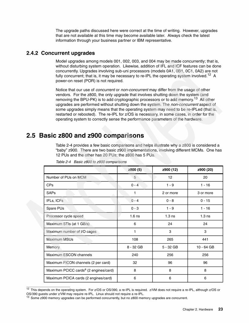
2.5 Basic z800 and z900 comparisonsTable 2-4 provides a few basic comparisons and helps illustrate why a z800 is considered a “baby” z900. There are two basic z900 implementations, involving different MCMs. One has 12 PUs and the other has 20 PUs; the z800 has 5 PUs.
Table 2-4 Basic z800 to z900 comparisons
12 This depends on the operating system. For z/OS or OS/390, a re-IPL is required. z/VM does not require a re-IPL, although z/OS or OS/390 guests under z/VM may require re-IPL. Linux should not require a re-IPL.13 Some z900 memory upgrades can be performed concurrently, but no z800 memory upgrades are concurrent.
z800 (5) z900 (12) z900 (20)
Number of PUs on MCM 5 12 20
CPs 0 - 4 1 - 9 1 - 16
SAPs 1 2 or more 3 or more
IFLs, ICFs 0 - 4 0 - 8 0 - 15
Spare PUs 0 - 3 1 - 9 1 - 16
Processor cycle speed 1.6 ns 1.3 ns 1.3 ns
Maximum STIs (at 1 GB/s) 6 24 24
Maximum number of I/O cages 1 3 3
Maximum MSUs 108 265 441
Memory 8 - 32 GB 5 - 32 GB 10 - 64 GB
Maximum ESCON channels 240 256 256
Maximum FICON channels (2 per card) 32 96 96
Maximum PCICC cardsa (2 engines/card) 8 8 8
Maximum PCICA cards (2 engines/card) 6 6 6
Chapter 2. Hardware 23

2.6 CHPID mappingIn pre-z900 systems, CHPID numbers were tied to the hardware layout. For example, the CHPID for the primary internal DASD on an MP3000 is FD. This is a fixed assignment and the user needs to build an IOCDS to match it. Some channels (or channel-like devices) require several CHPID addresses, even though only one CHPID address is actually used. This is termed blocking CHPID addresses. OSA adapters are the most common examples of such devices.
The combination of (1) a maximum of 256 CHPID numbers, (2) the presence of blocked CHPID numbers, and (3) a rigid tie between a CHPID number and the type or position of a hardware element made the whole CHPID addressing scheme complex and difficult to change without introducing errors. Use of ESCON Directors makes the situation more complex. The use of a single IOCDS by a group of systems (each with its own hardware configuration) makes the situation even more complex.
Errors in these hardware definitions (as seen by the operating system), especially when related to multipathing, can be difficult to diagnose and can bring down a system. Migration to a new machine, with different CHPID assignments, required reworking the IOCDS. This was (and is) a critical task that could delay productive use of a new system.
Maximum OSA-Expr cards (2 ports/card) 12 12 12
Maximum ICB-3 CF links (STI connection) 5 or 6b 16 16
Maximum ISC-3 CF links 24 32 32
Maximum CHPIDs 256 256 256
HMC required? Yes Yes Yes
Support Elements 2 2 2
External Power 1 phase 3 phase 3 phase
Concurrent memory upgrades no yes yes
MCM packaging 71mm square 127.5mm square 127.5mm square
L1 cache (per PUc) 256K/256K 256K/256K 256K/256K
L2 cache (per system) 8 MB 16 MB 32 MB
MBA chips 1 4 4
Optional battery feature no yes yes
Parallel channels no yes yes
Hipersockets yes yes yes
System models all 101-109 110-116,1C1-1C9
a. The actual maximum number of FICON, OSA-Express, and PCICC cards are interdependent.b. A CF-only machine may have 6 ICB-3 links. Other machines must retain a minimum of one STI con-nection to the I/O cage.c. I-cache/D-cache
z800 (5) z900 (12) z900 (20)
24 Technical Introduction: IBM zSeries 800

z800 and z900 machines permit the user to map (assign) CHPID numbers to hardware channels. This provides, in essence, another level of indirection in the addressing of “real” hardware. The intention is that CHPID numbers on a new system can be mapped to the same CHPID numbers used on the old system to address specific devices. This should reduce the complexity of IOCDS (and HCD/IODF) migrations from the old to the new system.
An additional benefit of CHPID mapping is that blocked CHPID numbers no longer exist. All 256 potential CHPID numbers can be used for real channels/devices. Unused ports, such as unactivated ports on an ESCON card, do not occupy CHPID numbers.
Mapping is done from the Support Element keyboard or HMC. The initial mapping is done by default rules or can be overridden by service personnel during installation. A CHPID Mapping Tool is available on Resource Link. This offers several ways to create new mapping definitions and produces an output file that can be loaded into the Support Element.
If no CHPID mapping is done, then default CHPID numbers are assigned to channels and the user’s IOCDS must match these numbers. When a z800 system is delivered, the accompanying documentation specifies the default CHPID assignments for all the installed I/O cards and ports.
You can access the CHPID assignment display on the Support Element using the navigation CPC Configuration -> Channel CHPID Assignment. Figure 2-8 on page 25 illustrates a typical display.
Figure 2-8 ITSO Channel CHPID assignment frame
channel location online assigned proposed cardcage slot jack standby CHPID CHPID reserved
A05C LG04 J.00 reserved 00 Gig Ethernet SW...A05C LG04 J.01 reserved 01 Gig Ethernet SWA05C LG05 J.01 reserved 03 Fast EthernetA05C LG06 J.00 reserved 14 FICON LC SWA05C LG06 J.01 reserved 15 FICON LC SWA05C LG11 J.01 reserved 05 ESCON 16 portA05C LG11 J.06 reserved 0A ESCON 16 portA05C LG11 J.07 reserved 0B ESCON 16 portA05C LG12 J.00 reserved 0C ESCON 16 portA05C LG12 J.01 reserved 0D ESCON 16 portA05C LG12 J.02 reserved 0E ESCON 16 portA05C LG12 J.03 reserved 0F ESCON 16 portA05C LG12 J.04 reserved 10 ESCON 16 portA05C LG12 J.05 reserved 11 ESCON 16 portA05C LG12 J.06 reserved 12 ESCON 16 portA05C LG12 J.07 reserved 13 ESCON 16 portA05C LG05 J.00 online 02 Fast EthernetA05C LG11 J.00 online 04 ESCON 16 portA05C LG11 J.02 online 06 ESCON 16 portA05C LG11 J.03 online 07 ESCON 16 portA05C LG11 J.04 online 08 ESCON 16 portA05C LG11 J.05 online 09 ESCON 16 port
Chapter 2. Hardware 25

Figure 2-8 illustrates the CHPID assignment display for the z800 used in the ITSO while writing this redbook. It is an unusually small system, but it provides a simple example of a CHPID assignment display. The CHPID assignments shown are the default assignments; we could change them (using the proposed CHPID column), but we had no reason to make changes. The reserved status means that the CHPID exists but is not defined in the current IOCDS. The slot value corresponds to a slot in the I/O cage; these slot numbers are labelled on the system frame. For example, CHPID 09 is on the ESCON adapter card in slot 11 and is jack 05 on this card. The jack numbers are printed on the face of the adapter cards.
The cage column is meaningful for a z900 system (which can have multiple I/O cages), but will always have the value A05C for a z800 system.
26 Technical Introduction: IBM zSeries 800

Chapter 3. Software
A z800 system runs the same software as a z900 system. This chapter briefly describes the operating system choices that apply to a z800 system. It also describes, in some detail, the steps involved in installing a z/OS ServerPac.
Table 3-1 summarizes current 64-bit capabilities by operating systems that might be used with the z800:
Table 3-1 Current 64-bit capabilities
The following maintenance should be applied for full functionality:
Operating System APAR CommentOS/390 V2R6-R10 OW51339 HCD Support (starts with V2R8 except in Japan)z/OS V1R1-R3 OW51339 HCD SupportOS/390 V2R6-R10 OW52993 IOCP Support (starts with V2R8 except in Japan)z/OS V1R1-R3 OW52993 IOCP Support
3
ESA/390 (31-bits) z/Arch (64-bits)
z/OS Version1 Releases 1, 2, and 3 No Yes
z/OS.e (based on z/OS 1.3) No Yes
OS/390 Version 2 Release 10 Yes Yes
OS/390 Version 2 Releases 8 - 9a
a. OS/390 2.6 is supported only in Japan.
Yes No
Linux for zSeries No Yes
Linux for S/390 Yes No
z/VM Version 4 Releases 1 - 2 Yes Yes
z/VM Version 3 Release 1 Yes Yes
VM/ESA Version 2 Releases 3 - 4 Yes No
VSE/ESA Version 2 Releases 3 - 5 No No
TPF Version 4 Release 1 Yes No
© Copyright IBM Corp. 2002 27
OS/390 V2R6-R10 OW52158 XES Support (starts with V2R8 except in Japan)z/OS V1R1 (only) OW52158 XES Supportz/OS V1R1-R3 OW52306 WLM MSU SupportVM/ESA 2.4.0 VM62676, VM62811, VM62942, VM62665z/VM 4.2.0 VM62938, PQ51738 (HiperSocket Support)VSE None
3.1 z/OS.ez/OS.e is z/OS with selected components “fenced” to prevent their use, and is unique to the z800. z/OS.e is not available for the z900 or S/390 machines. The goal is a much less expensive packaging of z/OS that is suitable for new workloads such as WebSphere, HTTP Server, SAP, J D Edwards, Peoplesoft, DB2 stored procedures, and so forth. IBM Redbooks usually do not discuss pricing details, but the pricing model used with z/OS.e is critical to understanding it and is briefly discussed in this section. Contact your marketing representatives for more detail.
z/OS.e is available in the form of a ServerPac and is installed in the same manner as any ServerPac. It is also available, for an additional fee, in the form of a SystemPac. The ordering process is the same as for a ServerPac, although various options and features (those fenced from z/OS.e) are not available for selection in the order.
z/OS.e has product number 5655-G52. The following specific documentation is available for it:
� z/OS and z/OS.e Planning for Installation, GA22-7504� z/OS.e Overview, GA22-7869� z/OS.e Licensed Programming Specifications, GA22-7868� Memo to new z/OS.e Licensees, GI10-0684
Except for these documents, all the remaining z/OS documentation (including subsystems, applications, utilities, and so forth) is common to both z/OS and z/OS.e.1
3.1.1 Specific limitationsz/OS.e must run in an LPAR, and the LPAR name must be ZOSExxxx (where xxxx represents any four characters). This is now a restricted LPAR name that can be used only for z/OS.e. Among other characteristics, a z/OS.e system must have an entry in the active IEASYSxx member specifying a new LICENSE system parameter as LICENSE=Z/OSE. A disabled wait state 07B is entered (with reason codes 23 and 24) to indicate an invalid startup, such as:
� LICENSE=Z/OSE, but the machine type and/or LPAR name do not permit z/OS.e operation, or
� The LICENSE parameter does not indicate Z/OSE, but the machine type and LPAR name requires z/OS.e.
TSO/E is limited to eight users logged onto the system at any given instant. z/OS.e is not intended for TSO services. A few TSO users are needed for systems programming activities and application setup. This is checked during LOGON command processing, allowing only eight TSO users to log on at the same time; it is equivalent to setting USERMAX in TSOKEYxx to eight.
If more than eight users try to log on, the following message is issued: IKJ56430I TSO LOGON rejected - maximum number of users reached. Note that Telnet logins directly to UNIX System Services are not limited.
1 Where they apply, of course. CICS manuals, for example, do not apply to z/OS.e.
28 Technical Introduction: IBM zSeries 800

In general, applications written in COBOL, Fortran, and Visual Age may not be used. Existing PL/I programs may be used, but new PL/I development is not permitted.2 IMS and CICS may not be used. A number of specific IBM products and components may not be used, including BookManager Read, DCE Application Support, GDDM, LANRES, BDT File to File, and BookManager Build. Only the current level of LE and JES2 or JES3 may be used.
DB/2 may be used and COBOL programs run under DB2 PIPI (as stored procedures) are allowed.3 C, C++, and Java applications and compilers are allowed. Applications written in assembler language (and not using any of the fenced facilities) are allowed.
The method for fencing the facilities not allowed under z/OS.e varies. Some facilities are not shipped with z/OS.e and cannot be ordered for it. Some facilities (including many interfaces to Language Environment (LE) services) are present, but are disabled.
Some fenced (disabled) functions may have indirect consequences. For example, GDDM is not available in z/OS.e. RMF is available. However, some of the RMF display functions use GDDM and these functions will not work under z/OS.e.
The license agreement for z/OS.e excludes use of CICS. LE is called by many CICS applications; if you attempt to initialize LE under CICS, the initialization will fail. Any attempt for a subsequent CICS LE application call to LE will receive an abend.
IMS and Batch applications attempting to initialize a LE environment for COBOL or FORTRAN will receive an abend. Other facilities and usage are prohibited by the license terms for z/OS.e. If you have specific concerns, you should examine the license terms closely.
Third-party software products may or may not run under z/OS.e, depending on the system facilities they require. If they are written in COBOL, for example, they will probably not run and are prohibited by the z/OS.e license terms. You will need to verify the status of such products with their vendors.
3.1.2 Pricing model
z/OS.e is licensed in units of z800 engines (CPs). A partial CP capacity cannot be licensed. The assigned MSU capacity of z/OS.e LPARs must not exceed that of the licensed number of engines. The call home data sent from the z800 to IBM may be used to verify proper use of z/OS.e.
Figure 3-1 on page 30 shows possible combinations that an installation can have when using z/OS.e. The first one shown is expected to be the most common one: a partition defined to run the customer’s new workload, under z/OS.e, and another partition running the traditional workload. The traditional workload can be executed under z/OS (first example) or OS/390 (third example). For pricing purposes, both configurations are known as a divided box.
The partitions in the figure that are executing z/OS.e should be defined with a capacity equivalent to the number of engines licensed for z/OS.e. If the z800 is a 4-way machine, you can license z/OS.e for one, two, three, or four processors (four does not make much sense for a divided box).4 If the defined capacity5 of the z/OS.e partition is one processor, then z/OS running in the other partition will be charged for three processors only (or the MSU equivalent of three processors).
2 Stated another way, the PL/I runtime functions of LE are available. The PL/I compiler may not be used.3 However, the COBOL compiler may not be used under z/OS.e, so these programs must be compiled elsewhere.
Attention: The information in this section is intended to provide a conceptual overview only. See your marketing representative for final and more complete information.
Chapter 3. Software 29

This environment gives the customer the possibility to break the machine in two pieces for software pricing purposes.
z/OS can be priced in two ways: zELC (similar to GOLC for the Enterprise 3000),or by sub-capacity pricing. Sub-capacity pricing can be aggregated to other z900 machines in the same sysplex. A full description of sub-capacity licensing is beyond the scope of this redbook; consult your marketing representatives for more complete information.
Figure 3-1 z/OS.e possible configurations
If z/OS runs on a z800 uncoupled, not in a sysplex environment, it is eligible for the zSeries Entry License Charge (zELC) model base pricing. zELC model base pricing prices all MLC software products based on the z800 processor model. The net effect of zELC pricing is a considerably lower software price for the smaller z800 systems. Please consult your marketing representative for specific pricing details.
When the z800 is physically coupled to other boxes in a Parallel Sysplex environment, customers can choose their base pricing model as (1) standalone zELC model base pricing, or (2) aggregate PSLC or WLC pricing, subject to WLC/PSLC terms and conditions. The crossover occurs when the benefits of zELC are outweighed by the benefits of an aggregate pricing model. When the number of MSUs in a Parallel Sysplex exceeds 70, the aggregate pricing may be more attractive.
In conjunction with any of these base z/OS operating system pricing options, the customer can have engine-based monthly pricing for z/OS.e, engine-based one-time charges for WAS, z/VM V4, and value unit-base one-time charges for data management and application development tools.
4 z/OS.e is always licensed in terms of an integral number of processors, expressed as MSU equivalents.5 Defined capacity is a hardware function managed through the SE/HMC. It is available for z800 and z900 systems. The system administrator can define a specific number of MSUs permitted by an LPAR. The hardware and WLM, working together, then manage the LPAR so that it does not consume more than the defined capacity MSUs. This management works over a four-hour averaging period.
z/O STrad itional
z /O S .enew
work loads
z /O S .enew
work loads
z /O S .enew
work loads
newwork loads
z /O S .enew
work loads
Traditiona l
z /O STrad itional
z/O STrad itional
IFL
z /O S .e P oss ib le C on figu ra tions
C F
z800
z800
z800
z800
z900
O S /390
30 Technical Introduction: IBM zSeries 800

zOS.e uses engine-based (PU) pricing and this is expressed in terms of MSUs. An MSU value from the following table is used to license z/OS.e. The intention is that these MSU values represent full processor engines (CPs) in the indicated environments; there is no provision to license part of a processor capacity for z/OS.e. When defining LPARs for the system, you do not need to dedicate CPs to z/OS.e LPARs.
Table 3-2 presents the configured MSU capacities of z800 systems for the purpose of z/OS.e licensing. The full capacity of the machine (second column) is evenly divided among the processors in the system. MSUs are integer numbers and the table (columns 3 - 5) reflects the roundoff of MSU values in the indicated situations.
Table 3-2 Configured MSU capacities - z800 systems
If only z/OS.e is used on a z800 system, the pricing and configuration scheme is straightforward. However, it may make sense to purchase both z/OS.e and z/OS for the same system. In this case, z/OS could be configured for the number of MSUs unused by the z/OS.e license. This makes the z/OS license less expensive.
Consider the sketch in Figure 3-2 on page 32. This example makes a number of important points. A complete processor (CP 1) is assigned to the z/OS.e LPAR. (We could run multiple z/OS.e LPARs with a total of 30 MSUs, using this assigned CP, without changing the concept; we could also define the capacity for the partition to be 30 MSUs and use both processors shared with other partitions.)
z/OS and its products are licensed for the remaining 30 MSUs of the system. This makes z/OS and its products considerably less expensive than if they were licensed for the whole 2066-002 processor. Keep in mind that z/OS can be priced using the z/ELC pricing model, PSLC or WLC (if the partition is connected to a sysplex).
MSU capacity if complete
system is used for z/OS.e
MSU capacity if 1 CP is used for
z/OS.e
MSU capacity if 2 CPs are used
for z/OS.e
MSU capacity if 3 CPs are used
for z/OS.e
0A1 (1 CP) 13 13
0B1 (1 CP) 20 20
0C1 (1 CP) 25 25
001 (1 CP) 32 32
0A2 (2 CPs) 44 22
002 (2 CPs) 60 30
003 (3 CPs) 84 28 56
004 (4 CPs) 108 27 54 81
Chapter 3. Software 31

Figure 3-2 z/OS.e and z/OS in LPARs
In the same figure, note the link between a CICS connector in a z/OS.e application and CICS under z/OS. CICS may not be used under z/OS.e, but CICS connectors may be used. Likewise, DB2 and IMS connectors may be used. Hipersockets, channel-to-channel adapters, and shared DASD may also be used to move or share data between z/OS.e applications and z/OS applications.
z/OS and z/OS.e can be part of the same sysplex. DB2 running under z/OS.e can be part of the same data sharing group as other DB2s running under z/OS. This is also true for JES2 MAS and a JES3 complex. There are some restrictions in a sysplex environment. For example, an automatic restart policy should not attempt to shift CICS to a z/OS.e partition.
Figure 3-3 on page 33 illustrates a different arrangement. In this example, the processor is the same z800 model 002, with two full-speed CPs. z/OS.e can be configured for one or both engines; this would be 60 MSUs (both) or 30 MSUs (one).
You can assign less than the licensed number of MSUs to a z/OS.e LPAR.6 In this case, we configured 30 MSUs for z/OS.e, but assigned only 20 MSUs to the z/OS.e LPAR. The remaining 40 MSUs are assigned to z/OS LPARs and z/OS and its various subsystems and applications should be licensed accordingly.
If you are running a z800 in a sysplex environment and use a WLC pricing model, then the Sub-Capacity Reporting Tool (SCRT) must be used to prepare reports that verify your compliance with the licensed capacity of the system. You must collect SMF record types 70 and 89, run the reporting tool, and send the reports to IBM.
SCRT can be obtained from the IBM Web site:
http://www.ibm.com/zseries/wlc_lm
From this site you can also download the SCRT User’s Guide; the guide will direct you through the process you have to follow in order to submit your data to IBM. If you are not using the WLC pricing model, then there is no need to use the SCRT tool.
6 But you cannot assign more than the licensed MSUs, of course.
z800 Processor model 002 (60 MSUs)
CP 1 CP 2
LPAR 1 LPAR 2 LPAR 3
z/OS.e
WASDB2CICS conn
z/OSProduction
CICSCOBOLPL/1etc.
z/OSTest
30 MSUs 30 MSUs
connector
32 Technical Introduction: IBM zSeries 800

The call-home facility will provide IBM the information to verify if you are complying with the terms and conditions for which you licensed your software.
Figure 3-3 z/OS.e and z/OS in LPARs, alternate arrangement
3.1.3 Middleware pricing methodologyTable 3-3 on page 34 lists the price model for the IBM middleware software, like DB2, on a z800 machine that has z/OS.e licensed for a number of engines. For example if you have a z800 model 003 with z/OS.e licensed for one engine (that is, 28 MSUs), then you will pay for DB2 (as an example) running under z/OS.e the zELC price of a 0C1 machine (25 MSUs). For the same DB2, running under z/OS on remaining partitions of the z800 model 003, you will pay the zELC price equivalent to a z800 model 002 (60 MSUs).
z800 Processor model 002 (60 MSUs)
CP 1 CP 2
LPAR 1 LPAR 2 LPAR 3
z/OS.e
WASDB2CICS conn
z/OSProduction
CICSCOBOLPL/1etc.
z/OSTest
20 MSUs 20 MSUs 20 MSUs
Chapter 3. Software 33

Keep in mind that these rules are valid both for z/OS and OS/390. Also remember that if the z/OS partition is part of a Parallel Sysplex, you can choose among zELC, PSLC or WLC pricing.
Table 3-3 License rules for middleware
3.2 Customized Offerings DriverThe Customized Offerings Driver is IBM program number 5665-343. It is a starter system that can be used to install z/OS or z/OS.e. In general, the Customized Offerings Driver would be used only if no other OS/390 or z/OS system were available to use as a driver for installing a new release of z/OS. This situation might occur for a new z/OS customer, or a new zSeries machine being installed in a location remote from other z/OS or OS/390 systems. The current Customized Offerings Driver, Release 1.17, is based on OS/390 V2R9. It is available for both 3380 and 3390 disks, but we consider only 3390 disks here.
The Customized Offerings Driver is intended only for use as a driver to install full z/OS (including z/OS.e) or OS/390 systems. It has very restricted functions and is not suitable for a general test or training system. The current Customized Offerings Driver release contains the following options and products:
BCP HCD ISPF JES2 SecureWay Security Server(RACF)SDSF SMP/E TIOC TSO/E SecureWay Communications Server(IP, SNA)DSF(V1R16) DFSMSdfp(V1R5) UNIX System ServicesDFSMS/MVS DFSMSdss LE High Level Assembler
The Customized Offerings Driver system (3390 version) restores to two 3390-3 volumes named D9ESY1 and D9ECAT. The first is the IPL volume. The Customized Offerings Driver system also includes a tape with stand-alone DSF (to initialize disks) and stand-alone DFSMSdss (to restore tapes). These programs can be IPLed directly from the distribution tape. The instructions (GI10-0615-04) supplied with the Customized Offerings Driver go through the disk initialization and restore process with step-by-step instructions.
z800 machine
0A2 with 1 z/OS.e engine
002 with 1 z/OS.e engine
003 with 1 z/OS.e engine
004 with 1 z/OS.e engine
003 with 2 z/OS.e engine
004 with 2 z/OS.e engine
004 with 3 z/OS.e engine
zELC license rules formiddleware under z/OS.e
zELC license rules formiddleware under traditional (z/OS, OS/390)
0C1
0C1
0C1
0C1
0A20A2
0A2
003
0B1
0B1
002
002
001
001
003
34 Technical Introduction: IBM zSeries 800

The Customized Offerings Driver does not include an IOCDS for your machine. Before you can install the Customized Offerings Driver, you must create an IOCDS that contains the minimum devices needed for it. This would be a tape drive, two 3390-3 drives, and a local 3270 console. In practice, you would want to include more 3390 drives to receive your ServerPac system or whatever else you are trying to install using the Customized Offerings Driver as a driver.
The IODF distributed with the Customized Offerings Driver has a large number of device addresses included. We arbitrarily selected a small subset of these to use in our first IOCDS. We created this IOCDS using a PC editor and used the stand-alone build process in the z800 Support Element to install it. We selected the following addresses:
Addresses Device Purpose00A1 3270 COD terminal; NIP, MVS console0F00-0F03 3270-X TSO terminals (VTAM major node DF00F1F)0320-033F 3390 Disks for COD, z/OS0390-0391 3490 Tape drives (with compression feature)
The IOCDS we built for this is listed in Appendix A, “Listings” on page 137. It is unlikely that you could use exactly the same IOCDS because you will probably have different CHPID, control unit, and unit addresses.7 However, you could probably adapt our IOCDS to your needs. The Customized Offerings Driver also includes basic definitions for SNA 3270s and TCP/IP interfaces. We did not use these. We used the Customized Offerings Driver both in basic mode and in LPARs, without any problems. Remember that it is an OS/390 system and cannot have more than 2 GB of central storage.8
The Customized Offerings Driver instructions describe a step-by-step IPL process. Briefly, it has these characteristics (assuming we restore D9ESY1 to address 0320 and D9ECAT to 0321):
Use the SE or HMC to LOAD 0320, with IPLPARM 032000IEA101A SPECIFY SYSTEM PARAMETERS FOR OS/390 02.09.00R 00,CLPA,SYSP=00........*01 ICH502A SPECIFY NAME FOR PRIMARY RACF DATA SET OR ‘NONE’1,SYS1.RACF*02 ICH502A SPECIFY NAME FOR BACKUP RACF DATA SET OR ‘NONE’2,NONE.....*03 $HASP426 SPECIFY OPTIONS ---3,COLD,NOREQ (Y to bypass integrity lock, if asked).......S VTAM......V F00-F03,ONLINE (TSO terminals)V NET,ACT,ID=DF00F1F0 (VTAM definitions for TSO terminals)S TSO.....
The userid DRVUSER with password DRVUSER is defined in RACF.
7 We used an IBM 2074 unit (the general replacement for a local 3174 control unit) to define the terminals at addresses 0A1 andF00-F03. A general description of 2074 customization is beyond the scope of this document. 8 We forgot this and provided 8 GB of central storage in basic mode. This produced an error message early in the IPL process, butprocessing was allowed to continue (using only 2 GB).
Chapter 3. Software 35

3.3 z/OS There are several current releases of z/OS and OS/390 that support the z800 machines:
Table 3-4 OS/390 and z/OS releases that support z800
The current release of z/OS is z/OS V1.R3. All releases of z/OS support z800, and z800 support is available for OS/390 V2.8, 2.9, and 2.10.9 z/OS 1.3 incorporates several enhancements and changes. These enhancements include the following.
Security support Integrated Cryptographic Support Facility (ICSF) and the cryptographic coprocessor support international cryptographic standards including personal identification number (PIN) processing, message authentication, and Rivest-Shamir-Adelman (RSA), the de facto public key algorithm standard. It also supports the Advanced Encryption Standard (AES) and the Derived Unique Key Per Transaction (DUKPT) algorithms.
The AES algorithm satisfies all National Institute of Standards and Technology (NIST) requirements including 128-bit keys. The DUKPT algorithm supports point-of-sale terminals that do not yet support the Triple DES encryption algorithm. z/OS 1.3 enables PKI, the certificate authority that provides digital credentials to participants and a public-key cryptographic system that uses these digital credentials to help ensure overall message integrity, signature verification, and user authentication.
PKI is a component of z/OS Security Services that is always enabled and works closely tied to RACF. It is a complete Certificate Authority (CA) package that fully manages the life cycle of a digital certificate. It can also be used to validate certificates for z/OS applications.
OS/390 UNIX System Services supportSeveral operator commands have been added to z/OS to allow operators to better manage the system.
� The first command is modify; this command gives the operator the capability to recycle the OMVS address space and associated UNIX workload in order to avoid having to re-IPL mission-critical systems.
The format of the command is F OMVS,SHUTDOWN. This command initiates shutdown of the UNIX System Services environment,and signals are sent to interested parties to warn of an imminent shutdown. F OMS,RESTART is used to restart the UNIX System Services environment.
� The second command is a new display function; D OMVS displays the status of a shutdown or restart request. System administration tasks are relieved by the capability added to the system to automatically allocate an HFS file system if one does not exists; the current automount policy can be displayed so the administrator can easily determine
Release Available End of Services Market now
OS/390 V2R8 October 1999 September 2002 no
OS/390 V2R9 March 2000 March 2003 no
OS/390 V2R10 October 2000 September 2004 no
z/OS V1R1 March 2001 March 2004 no
z/OS V1R2 October 2001 October 2004 no
z/OS V1R3 March 2002 March 2005 yes
9 In Japan (only) support is also available for OS/390 2.6.
36 Technical Introduction: IBM zSeries 800

the automount policy that is in effect. zFS performance and management are improved, so it is easy to deploy this file system.
64-bit supportAdditional system services are included in z/OS 1.3 to support the 64-bit virtual operating environment. These services include the capability to LINKX, LOAD, XCTLX, ATTACHX, and SYNCH to routines getting control in AMODE(64). Also included is the capability of PC routines getting control in AMODE(64). Recovery routines, via ESTAEX, ESPIE can get control in AMODE(64). Eight-byte adcons are supported during nucleus load, in load module fetch, in program object fetch, and in LLA processing for cached load modules.
m-sys for operation and setup m-sys for operation was introduced in z/OS 1.2 to improve system manageability by reducing operations complexity, increasing operational awareness, and reacting faster to complicated recovery situations.
Enhancements in release 1.3 include the capture of IPL statistics, interaction with the HMC/SE to activate or deactivate a CF partition, identification of long-blocking tasks in contention so they can be terminated, reaction to auxiliary storage shortage, adding local page datasets, assisting partitioning a system from a Parallel Sysplex, rebuilding after a CFRM policy switch, starting duplexing processes, customizing dump options, taking SVCDUMPS, modifying SLIP traps, and so on.
In general, m-sys for setup manages the system infrastructure for setup. It can ease the installation of a z/OS system, and is targeted towards system programmers with little or no experience in UNIX, MVS or either. It provides basic field definitions, suggested values, and practical ranges for products that are to be configured. For UNIX Services configuration, m-sys can be used to customize file systems and system resources.
Workload Manager support Starting with z/OS 1.3, Workload Manager supports only goal mode; the support for compatibility mode has been removed. Sample JCL (IWMINSTL) and service definitions (IWMSSDEF) are provided with the operating system to simplify the process of installing a service definition and activating a service policy.
The enclave service class reset allows an installation to change the performance characteristics of an original independent enclave transaction, assign it to a different service class, quiesce all work in an enclave, resume, or reclassify it. The objective it to give the installation more control of independent enclave transactions.
Data access and storage management VSAM has been enhanced to allow access of buffers with 64-bit real storage backing for all VSAM record organization. All VSAM data sets have I/O performed using the media manager instead of the VSAM block processor; the use of media manager should result in improved system throughput.
VSAM RLS lock structures exploits System-Managed CF Structure Duplexing to provide improved availability. All systems in a Parallel Sysplex must support duplexing to use this function.
The modify catalog command allows the installation to periodically reset the statistical information and gather data to create a profile of their CAS performance. The capability to ENABLE/DISABLE data set name validation is also added to the modify command. It supports the extended storage groups that define a storage group in which SMS may extend data sets to when there is an insufficient amount of storage on any volume in the primary storage group.
Chapter 3. Software 37

It also supports the definition of an overflow storage group, a pool of storage designated by the user to handle periods of high demand for primary space allocation. z/OS 1.3 also introduces the concept of a common recall queue (CRQ) for DFSMShsm; this gives the user the ability to maintain the recall queue in a CF list structure, accessible by the entire CRQplex (all DFSMShsm hosts connected to the same CRQ); load balancing can be achieved between the host because requests can be selected by any host.
3.4 VM/ESA and z/VMTable 3-5 lists several current releases of VM.
Table 3-5 Current VM releases
The recent release of z/VM 4.2 is not uniquely tied to the z800 series, but it provides important features likely to be used by z800 owners, such as:
� HiperSockets.� 64-bit mode, as well as 31-bit mode.� Operation in an LPAR with IFL engines.� Use of PCI cryptographic hardware (PCICC and PCICA), as well as earlier cryptographic
coprocessor support:
The PCICC and PCICA support permits the use of Secure Socket Layer (SSL) hardware acceleration.
� Fast CCW translation support tuned for Linux guests (in z/VM 4.1).� Enhanced page fault handling tuned for Linux (in z/VM 4.1).� Fast CCW translation and minidisk cache operation for 64-bit I/O, important for 64-bit
Linux.� Observer support that permits an authorized virtual machine to watch line mode output
from another virtual machine. This is intended to make it easier for a “master” Linux virtual machine to automatically monitor and control other Linux guests.
� TCP/IP security improvements to prevent common denial of service attacks.� The z/VM Administration Facility, which essentially replaces the VIF function available
earlier, providing simplified VM administration and operation where usage is confined to running Linux guests.
3.4.1 HiperSockets and VMHiperSockets are an important addition to z/Architecture and are briefly described in “HiperSockets” on page 77. z/VM 4.2 extends the function:
� By allowing VM guests to use the four “real” HiperSocket resources, just as if the guest were not running under VM
� By creating virtual HiperSocket network adapters that are independent of the “real” HiperSocket hardware resources
Release Available End of service Marketednow?
z800support?
VM/ESA V2R3 March 1998 March 2002 no no
VM/ESA V2R4 July 1999 no yes
z/VM V3R1 February 2001 yes yes
z/VM V4R1 July 2001 March 2003 no yes
z/VM V4R2 October 2001 December 2003 yes yes
38 Technical Introduction: IBM zSeries 800

The virtual HiperSockets create what are known as guest LANs.10 The combination of abilities, using real and virtual HiperSockets, provides a key element for very powerful clustering solutions and server consolidation solutions in systems supported by z/VM 4.2. (The virtual HiperSockets are available on z800, z900, 9672 G5/G6, and Multiprise 3000 machines.) An extended description of the potential uses is beyond the scope of this redbook. PTFs for APARs VM62938 and PQ51738 are required to use HiperSockets with z/VM 4.2.
3.4.2 z/VM System Administration FacilityThis is a recent feature of z/VM and is intended to help manage multiple Linux guest images. It is a replacement for the earlier Virtual Image Facility (VIF) function. VIF was a greatly-reduced version of VM that was managed solely through Linux line commands. CMS was not available. While VIF provided useful functions (targeted at installations with no VM skills), most users found it too restrictive. The new System Administration Facility provides improved versions of the VIF functions, with more general access to VM controls.
The Administration Facility assumes you have an unmodified VM system and that all changes to the VM directory will be made by using the Administration Facility. Skilled VM users may be able to make system changes using CMS, but this may result in a broken system if such changes are not transparent to the Administration Facility.
In general, a system using the Administration Facility is expected to be devoted to running Linux images. It is a general VM system and potentially could run other guests, such as z/OS or a large group of CMS users. However, running guests other than Linux is likely to involve VM administrative actions that are not compatible with the Administration Facility.
The Administration Facility is used by entering line commands from a CMS session or from a Linux image. A Linux image must be enabled to issue Administration Facility commands, and any number of images might be so enabled.
Figure 3-4 System Administration Facility
The sketch in Figure 3-4 provides an conceptual description of the System Administration Facility under z/VM. VMADMIN is a server function embedded in z/VM. Systems Management Clients communicate with it and provide the user interface; these clients can be used from CMS and/or Linux. At least one Linux image, with the Systems Management Client, is assumed to be installed and in usually known as Linux0 (Linux zero) or the Master Linux.
10 This terminology was selected because the term “virtual LAN” is already used for a completely different purpose and a new term was needed to avoid confusion.
CMS Linux
Systems Management Client
Management Client
Linux Linux Linux
z/VMVMADMINServer
Systems
TCP/IP
Linux0 Linux1 Linux2 Linux n
LAN
Chapter 3. Software 39

z/VM can use a single “real” LAN interface to provide individual virtual LAN interfaces to each Linux image. This is not required. You can elect to assign a real LAN interface to some of the Linux images, although this becomes impractical if a large number of Linux images are involved. You could also use HiperSockets to connect some or all of the images on a very fast internal LAN.
Because the basic Linux interface is through an ASCII Telnet connection, you will normally have an external TCP/IP LAN connection of some type for each Linux image. A discussion of all the possible variations of TCP/IP connectivity that are possible is beyond the scope of this redbook.
In principle, systems administrators can perform almost all their work from the Linux0 image, using the Administration Facility commands. In this case, little VM skill is required. In practice, it may be desirable to manage some performance and monitoring functions from CMS and some VM skill is required to do this.
It is also possible, using new functions in z/VM 4.2, to implement powerful global controls to manipulate and manage all the Linux images. The Administration Facility provides a few basic commands to control all the Linux images; more powerful and intelligent controls can be built using VM functions and will require some VM skills to install and use.
3.4.3 VM in an IFLz/VM can be used in a z800 IFL. However, a limited set of VM facilities are available in an IFL environment. In general, VM functions (including CMS) that are needed for basic system administration are available, while functions associated with a VM production environment are not available. The System Administration Facility is available.
At the time of writing, IBM was still refining the exact rules for which VM functions and products can be used in an IFL.
3.4.4 VM cryptographic support for Linux imagesVM will assist Linux images in using the PCICA and PCICC cryptographic hardware. The hardware features are required; VM does not emulate them. The VM images may be in an IFL or using a normal-function CP. There is no particular limit to the number of Linux images that can use these functions. The hardware cryptographic processors (the coprocessors and the PCICC adapters) contain 16 sets of various registers, to permit each of the maximum of 16 LPARs to have its own environment. This set of 16 registers is not a factor (and not a limiting factor) when VM provides virtual cryptographic processors for VM guests.
A software enhancement, PTF VM62905, is required to add this cryptographic support.
3.5 LinuxLinux can be run three ways on a z800:
� It can run in basic mode, as the only operating system on the machine. (However, it cannot use IFLs in this manner.)
� It can run in an LPAR, using either IFL processors or general (CP) processors.� It can run under z/VM, using either IFL processors or general (CP) processors.
40 Technical Introduction: IBM zSeries 800
The same Linux distribution can be used in any of these ways, and Linux cannot detect in which environment it is running. Each Linux image can be a 32-bit version or a 64-bit version. In general, running a single Linux in basic mode is probably unusual. A choice between the other modes involves many factors, including the following:
� S/390s (including z/Series machines) have a maximum of 15 LPARs. If Linux is run directly in LPARs, this means a maximum of 15 Linux images (assuming no other workload on the system needs LPARs).
� Running directly in LPARs means that z/VM and z/VM skills are not required.� Careful planning may be needed to allocate I/O devices (disks, LAN interfaces) to the
LPARs. Also, system memory must be divided among the LPARs in a static allocation.� In principle, running directly in an LPAR offers slightly better performance than running
under z/VM. (In practice this may not be true.)� Each Linux must be individually managed through a Telnet interface.� Many Linux images can be run under z/VM. There is no reasonable limit, other than total
system performance and span-of-control issues.� z/VM can share real memory resources among all the images running under it.� z/VM can share LAN interfaces among images by creating virtual internal LANs.� z/VM potentially can provide group-management functions for multiple Linux images.
Basic elements of this are available now, but work is required to provide refined controls.� Linux images running under z/VM might offer slightly less performance due to VM
overhead. (In reality, they might also offer better performance due to dynamic sharing of real memory.)
� Some VM skills are needed, even if the Administration Facility (see “z/VM System Administration Facility” on page 39) is used.
You can use a mixture of these methods. You might run several Linux images in LPARs, and run more Linux images under z/VM in another LPAR. While it may appear that there are too many options, the best path is often apparent after you consider the exact nature of your Linux workloads.
3.5.1 32-bit and 64-bit LinuxThe z800 provides 64-bit hardware. It can run in 24-, 31-, and 64-bit addressing modes. The addressing modes are set by the operating system or by applications (in the case of z/OS). Linux distributions are available for both 31-bit and 64 bit addressing modes.11 Either mode can be used in any LPAR, or under z/VM version 4 or later. (Either mode can be used in basic operation, without LPARs, if IFLs are not involved.)
There is a general perception that 64-bit Linux (and UNIX) systems are “better” than 32-bit systems. However, this may not always be true. Consider the following:
� 64-bit Linux and UNIX may have mixed meanings. Traditionally, the “bit size” of these systems corresponded to the size of an int variable. This is not always the case with 64-bit systems. Some implementations retain an int size of 32 bits (primarily for programming compatibility), but have 64-bit pointer sizes. This breaks any program that uses int variables as pointers. Conversion from a 32-bit program to a 64-bit program usually involves more than a simple recompile.
� Can 64-bit Linux run 32-bit programs with 32-bit addressing? It should, provided proper care is taken to use a set of compatibility libraries during compilation of code. We were not able to verify this at the time of writing because we did not have a 64-bit Linux for zSeries distribution that included all the necessary IBM OCO modules.
� Virtual memory is not free if paging space is required. Paging space means disk space. A single 64-bit program that attempts to use the full 64-bit addressing range could easily fill
11 The terms 32-bit and 31-bit are equivalent in this discussion.
Chapter 3. Software 41

all the paging disks on your system (and all the disks you could possibly buy), and then fail because the system ran out of paging space. In the process or doing this, it would largely consume the I/O resources of your system and severely inconvenience other users.
Practical use of 64-bit systems requires artificial constraints on virtual memory usage, and these constraints must be managed by the system and administered by someone.12
3.5.2 Linux distributionsIBM does not distribute Linux. IBM does contribute to the open source efforts that produce Linux, but has no special control over when (and if) its contributions are incorporated into the Linux kernel or the various Linux distributions. SuSE, Turbolinux, and Red Hat are major providers of Linux distributions for S/390 and zSeries machines.
IBM markets middleware, such as DB2, that runs under Linux. This is priced software and is not open source material.
IBM generally contributes open source patches for the Linux kernel that support various IBM hardware features. Over time, these patches are usually incorporated into the standard Linux kernel. Perhaps the best known of these patches provided Linux support for CKD disks. (This patch is now part of the standard kernel.)
The complete process takes time, and often goes like this:
1. IBM announces and ships a new hardware feature, such as HiperSockets.
2. IBM develops and releases patches to the Linux kernel that support the feature. The first set of patches are alpha code, followed later by beta code as the patches become more stable. (Both names indicate early releases, with alpha code meaning a very early release.) In some cases, this early code is available when the new product or function becomes generally available.
3. Advanced customers may want to download these patches, rebuild a Linux kernel, and try the functions on their new hardware.
4. A few functions involve IBM proprietary technology and are released only as object code. (Support for LCS LAN devices and cryptographic engines are examples of this category.)
5. The patches may become part of an odd-number standard kernel. The odd-number kernels are considered development kernels, and the even-number kernels are considered production kernels.
6. The patches may become part of the next even-number kernel and are considered ready for production.
7. The even-number kernel is used to build new distributions, and these are what production-oriented users want.
8. Various application vendors (fee) or contributors (free) might use the new functions at their own pace.
This whole process takes time and this is why IBM cannot “announce” a Linux release that uses the new Linux-oriented features of the z800 family. Alpha-level patches for some of the new functions may be available when the first z800s are shipped. Complete, standard Linux distributions that use all the new functions might be up to a year away.
12 The same exposure exists with 32-bit systems, of course, but the degree of exposure is less.
42 Technical Introduction: IBM zSeries 800
3.5.3 Linux installationThis section describes the steps we used for our Linux for S/390 installation. It contains no “new news” for users with Linux for S/390 experience, but it may be interesting for readers who have not worked in this area.
For our installation we used a SuSE distribution with a 2.4.7 kernel (31-bit mode). A CD image was downloaded from the Internet. (Another way of getting the installation CD is to buy it directly from SuSE, together with the support services.)
We used the SuSE distribution because it integrates open source Linux code and IBM Object Code Only (OCO) modules. The OCO modules are needed for interfaces to IBM LAN hardware, among other functions.
To install Linux for S/390 on our IBM 2066 processor, we followed performed the following tasks:
� Planned the network and storage setup� Prepared and activated a hardware configuration (IOCDS)� IPLed the Linux ramdisk image from the HMC CD-ROM drive, using the installation CD� Performed the initial customization using the HMC console to define enable network
access to the ramdisk image � Performed installation routines and post-installation customization (if needed), using a
network-attached CD-ROM drive and console � IPLed the Linux system from disk
These steps are discussed in detail in the following sections.
Step 1. Network and storage planning Our z800 LAN interface (an OSA Express Fast Ethernet card) could use both LCS mode and QDIO modes of operation. QDIO mode is a newer, more efficient mode of operating the OSA Express adapter. Using QDIO mode is a bit more complicated than using the standard LCS mode. We used both modes.
We defined the following network parameters, many of which were arbitrarily chosen by us:
Example 3-1 Basic network parameters
Read channel device number (LCS) 0x0e20Relative port 0
Full host name linux.raptor.itso.ibm.comHost name linuxDomain name raptor.itso.ibm.com
Host IP address 10.0.0.1Network mask 255.255.255.0Broadcast address 10.0.0.255Gateway address 10.0.0.254Name server address noneMTU 1492Workstation network address 10.0.0.3Channel device numbers (QDIO) 0x0e30,0x0e31,0x0e32 (read, write, data)
Portname RPTRFET1
Note that the device addresses in these parameters (such as E20, E30, and so forth) must match addresses defined in the IOCDS. These addresses were quite arbitrary. Also, the portname parameter that is part of a QDIO installation was arbitrary.
We decided to use only two 3390-3 volumes for Linux; this is adequate for a basic installation. We then made a few basic storage decisions:
Chapter 3. Software 43

� We elected to define several filesystems:/ (root)/var/tmp (mounted with the NOSUID option)/usr (could be RO if shared by multiple Linuxes)/home (mounted with the NOSUID option)
We also defined a separate swap partition.
� We noted that a CKD DASD volume is limited to three usable Linux partitions.� A single 3390-3 DASD volume has approximately 2.4 GB usable capacity after it is
formatted into 4K blocks. (4K is the most common block size for Linux.)� If partitions lager than a single DASD volume, the Logical Volume Manager (LVM) must be
used. We did not use it.
For our installation we used two 3390-3, which we partitioned as follows:
Volume 0x0322 /dev/dasda <<< 0322 will be the boot addressPartitions on 0x0322
/ /dev/dasda1/tmp /dev/dasda2swap /dev/dasda3
Volume 0x323 /dev/dasdbPartitions on 0x0323
/home /dev/dasdb1/usr /dev/dasdb2/var /dev/dasdb3
Step 2. Preparation of hardwareHardware configuration is defined using the process described in “LPAR setup and examples” on page 74. That section contains a working example of how to set a very simple logical partition for LINUX.
For our initial Linux installation we defined the following:
� An LPAR with 128 MB storage, using an IFL� A disk (DASD) controller and disk volumes� A network port
Step 3. IPL from the distribution CD-ROMTo IPL the Linux distribution CD from HMC CD-ROM, follow this procedure:
1. Log onto the HMC as SYSPROG.2. Find the CPC Recovery task list.3. Double-click the Groups icon in the Views area.4. Double-click the Defined CPCs icon in the Work area.5. Drag and drop the icon representing your CPC to the Single Object Operations icon in
the Task area.6. Double-click the Groups icon in the Views area.7. Double-click the Images icon in the Work area.8. Insert the Linux installation CD (with the ramdisk image) in the CD drive on the HMC. Drag
and drop the icon representing your Linux partition to the Load from CD-ROM server icon in the Task area.
9. Follow the instructions on the screen, until you see the message: Load from CD-ROM or server completed successfully.
44 Technical Introduction: IBM zSeries 800

Step 4. Initial customizationThe initial customization of the ramdisk Linux is through the Operating System Messages window on the HMC or SE. No LAN connections are possible because networking parameters have not been defined yet. Drag and drop the icon representing your Linux partition to the Operating System Messages icon in the Task area. You can send commands to Linux by clicking the Respond or Send pushbuttons. Initial Linux messages should be visible in the Operating Systems messages window.
Referring to the messages used in our SuSE version, select option 9 and then 1 to see whether channels defined for network devices have been recognized by Linux. If not, correct the IOCDS definitions. If they are visible, select option 9 to get back to the main menu and move on. Do not be alarmed that mass storage devices are not seen in the initial device listing.
The exact network customization responses depend on whether LCS or QDIO interfaces are being used. We used LCS for our initial installation, but we also include a few notes about QDIO use.
OSA Express Fast Ethernet in LCS modeFor LCS mode of the OSA Express Fast Ethernet Adapter, select option 2 and follow the instructions on the screen. Use the default parameters where possible (see example in “Basic network parameters” on page 43). Go to “Step 5. Installation and post-installation routines” on page 45 when you are finished.
OSA Express Fast Ethernet in QDIO modeThe installation procedure for the SuSE LINUX 2.4.7 distribution has a minor bug that prevents the automatic setup QDIO mode. However, this setup can be performed manually. To do this, select option 0 (no network). For security reasons, set up the root temporary password first:
passwd root
Then set up the network, using the following commands:
echo ‘noauto’ >/proc/chandevecho ‘qeth0,0x0e30,0x0e31,0x0e32,0,0’ >/proc/chandevecho ‘add_parms,0x10,0x0e30,0x0e32,portname:RPTRFET1’ >/proc/chandevinsmod qdioinsmod qethifconfig eth0 10.0.0.1 netmask 255.255.255.0 broadcast 10.0.0.255 up/etc/rc.d/inetd start/etc/rc.d/portmap start
Step 5. Installation and post-installation routinesThe CD we booted from the z800 HMC provided a Linux ramdisk. The same SuSE CD also contains the files necessary to install a “real” Linux. This installation cannot be done from the HMC; it must be done over a network.
We placed a PC (running a SuSE PC version) on the same subnet as our z800 and used it as an NFS server. The ramdisk Linux (on the z800) accesses the NFS server to obtain the Linux modules that will be installed on our z800 disks.
The following steps walk through the main installation process. First, on the PC that will be the NFS server, we issued these commands:
mount /dev/hdc /mnt/cdrom (mount the CD ROM)/etc/rc.d/nfsserver start (start the NFS server)ping -c 5 10.0.0.1 (check connectivity to the z800)
Chapter 3. Software 45

telnet 10.0.0.1 (connect a telnet session to the z800)
Working through the Telnet session to the z800 (which is running the Linux ramdisk system), we issued these commands:
insmod dasd dasd=0x0322,0x0323 (install the CKD disk driver)
dasdfmt -f /dev/dasda -b 4096 (format our two disks)dasdfmt -f /dev/dasdb -b 4096
fdasd /dev/dasda (partition the disks)fdasd /dev/dasdb
yast (start YaST, the SuSE administration tool)
Using YaST is fairly straightforward. Since the installation dialog may vary with the distribution release, only the main points are listed here. We used default parameters wherever possible. The milestones of the installation are:
1. Choose Installation via NFS. Specify your workstation IP address as the NFS server address, and /mnt/cdrom as the installation directory.
2. You are Installing Linux from scratch.
3. Remember to Select swap partition, assuming you want one. (For our installation, we used 0322:3).
4. Choose Do not partition harddrives. They are already partitioned.
5. In the CREATING FILESYSTEMS screen, first choose Mount points for your filesystems and then format all the filesystems with Normal Format. You will not be allowed to proceed if you do not format the filesystems.
6. First Load Configuration and then Start Installation. In our installation, we selected the default SuSE Standard configuration to load, as it was the most complete one.
The installation process takes only a few minutes. After it completed, we stopped the NFS server on the PC, unmounted the CD, and removed it. In later trials, when we decided to use QDIO as our LAN interface, we needed to perform the following steps. When LCS was used, we could immediately IPL our new Linux system on the z800.
Post YaST setup for network in QDIO modeOur SuSE version could not automatically configure a QDIO interface. We assume this will be fixed in later SuSE releases. To bypass the problem in our release, we performed the following steps while still running in the Telnet session connected to the ramdisk Linux on the z800. After YaST has finished its installation processes, we issued the following commands:
mkdir /mnt/newrootmount /dev/dasda1 /mnt/newrootcd /mnt/newroot/etc
We used vi to edit the chandev.conf and modules.conf files in the /mnt/newroot/etc directory.
� In modules.conf, we changed:
alias eth0 off
to:
alias eth0 qeth
� In chandev.conf, we added the following lines:
noautoqeth0,0x0e30,0x0e31,0x0e32,0,0add_parms,0x10,0x0e30,0x0e32,portname:RPTRFET1
46 Technical Introduction: IBM zSeries 800

As an alternative to using vi, you may issue the following commands (remember to adjust the parameters to your values) while in the /mnt/newroot/etc directory:
echo ‘alias eth0 qeth’ >>modules.confecho ‘noauto’ >>chandev.confecho ‘qeth0,0x0e30,0x0e31,0x0e32,0,0’ >>chandev.confecho ‘add_parms,0x10,0x0e30,0x0e32,portname:RPTRFET1’ >>chandev.conf
Step 6. IPL the new Linux system from diskThe first time the new Linux system is run, it will automatically complete several additional installation tasks. To IPL the z800 Linux system from disk, do the following:
� Log onto the HMC as SYSPROG.� Find the CPC Recovery task list.� Click the Groups icon in the Views area.� Click the CPC Images icon in the Work area.� Drag and drop the icon representing your Linux partition to the Load icon in the Task area.� Input your boot disk address (0322) to the Load address field.� Click OK.� Wait until you see the message: Load completed.� Drag and drop the icon representing your Linux partition to the Operating System
Messages icon in the Task area.� Change root’s password when asked to do so. After this is done, a number of installations
scripts will run automatically. After the last installation script runs, you should be able to log on to the system from the network.
� An optional task is to edit the /etc/fstab file and substitute nousid for default for /tmp and /home filesystems. The easiest way to do this is to log onto Linux from a workstation and use the vi editor.
� To shut down Linux, use the shutdown command:shutdown -h now
This shuts the system down immediately. To shut down and automatically restart it, use:
shutdown -r now� The z800 Linux installation is complete.
3.5.4 Setting up a HiperSockets LAN for LinuxWe installed a HiperSocket connection for Linux. This requires additions to the IOCDS definitions, and the relevant definitions are included in the largest IOCDS listing in the appendix. HiperSocket definitions in Linux are slightly different from Ethernet QDIO definitions. The following files must be edited:
� /etc/modules.conf,
� /etc/chandev.conf, to define a Hipersockets channel device,
� /etc/rc.config, to define your network parameters.
The changes we made to these files are as follows
/etc/modules.conf# The following line is an alias for Fast Ethernet port in QDIO modealias eth0 qeth# The following line is an alias for HiperSockets portalias hsi1 qeth
/etc/chandev.confnoauto
# The two following lines describe a Fast Ethernet port in QDIO mode
Chapter 3. Software 47
qeth0,0x0e30,0x0e31,0x0e32,0,0add_parms,0x10,0x0e30,0x0e32,portname:RPTRFET1
* The two following lines describe a HiperSockets portqeth1,0xe000,0xe001,0xe002,0,0add_parms,0x10,0xe000,0xe002,portname:RPTRHPR1
/etc/rc.config# We have changed the lines containing the keywords# NETCONFIG, IPADDR_n, NETDEV_n and IFCONFIG_n# to the values specified below which are consistent with our previous examples. # Naturally your network paramenters may vary# The ..._0 parameters are for Fast Ethernet and the ..._1 parameters are for HiperSockets
NETCONIFG = “_0 _1”
IPADDR_0 = “10.0.0.1”IPADDR_1 = ‘10.1.0.11”
NETDEV_0 = “eth0”NETDEV_1 = “hsi1”
IFCONFIG_0 = “10.0.0.1 netmask 255.255.255.0 broadcast 10.0.0.255 up”IFCONFIG_0 = “10.0.1.11 netmask 255.255.255.0 up”
After making these changes, they can be activated with the following commands:
rcchandev reloadSuSEconfig
As you can see, we defined a new network segment for Hipersocket LAN. To verify that it is up and running, it can be pinged as follows:
ping -c 5 10.1.0.11
If you are setting up another node of the HiperSocket virtual LAN, remember to use the same value for the portname parameter (RPTRHPR1, in our examples).
48 Technical Introduction: IBM zSeries 800

Chapter 4. Discussion topics
This chapter provides further discussion of a number of interesting or important areas concerning z800 systems. A short introduction is included for some of the topics for readers not familiar with z900 developments. There is no special order to the topics.
4.1 Parallel channel planningz800 systems do not have parallel channels.1 Furthermore, no future IBM processors will have parallel channels. If you have parallel channel devices, you need to do some planning. Plans typically involve the following choices:
� Retire the devices.2 This is not as trivial as it may sound. Parallel channel tape and DASD devices are probably quite old and ready for retirement. Maintenance costs may exceed the cost of replacement devices using ESCON channels, and newer DASD devices have far greater capacity and performance.
� Purchase converter boxes to connect parallel devices to ESCON channels. IBM made such converters some time ago (IBM 9034, often known as Pacer units), but these are no longer manufactured. IBM recommends the use of the Optica product, described in 4.16, “Optica planning” on page 94. The IBM 9034 units may also be used, but these cannot be ordered through normal IBM ordering channels.3
� Keep only selected parallel devices and consolidate them onto as few channels as possible.
The most typical parallel devices that installations might want to keep include:
� IBM 34xx tape drives (“round tapes”), kept for some required archival functions
� IBM 3174 control units, used for MVS 3270 consoles and TSO/CICS 3270 terminals
� Various impact line printers
4
1 Parallel channels are often known as “bus and tag” or OEMI channels, named for the functions of the two cables used for thesechannels.2 We use the term devices here to include the associated control units. It is the control units, of course, that actually use the channels.3 We understand that IBM Global Financing has a limited stock of used 9034 units; you might want to consider this source.
© Copyright IBM Corp. 2002 49

There are often valid reasons for keeping these devices. However, we suggest that they can readily be consolidated onto a reduced number of channels. For example, a single channel could probably handle a mixture of all of the devices mentioned here. You might not normally mix tape drives with other devices on the same channel, but this depends on how often the tape drives are used. Typically, the older drives are so rarely used that their channel sharing characteristics can be ignored.
Most end users have migrated away from “real coax-attached” 3270 terminals and the use of 3174s has declined. Also, increasing use of many LPARs makes the use of one or two IBM 2074 units more attractive than using a large number of 3174s. The non-SNA IBM 3174s (including ESCON models) are used for z/OS operator consoles, and one 3174 is needed for each LPAR because 3174s cannot be shared by multiple LPARs. An IBM 2074 unit can be shared by multiple LPARs and connects to TN3270 client sessions on PCs, while appearing as multiple local, non-SNA 3174s to the operating system.
4.1.1 Byte multiplexorA few parallel devices may require byte multiplexor channels.4 Typically, there are no modern direct replacements for these devices. Few customers still use these devices, and each might be considered as a special case. Possibly EP and PEP lines are the most common of these.5 The ESCON-to-parallel converter units may support such devices; you should check with the manufacturer for the latest information. The older IBM 9034 units (sometimes known as Pacer units) do support byte multiplexor modes, but may not have been tested with your particular device types. Again, we suggest you consider these as special cases and discuss them with your marketing representatives.
A 9034 unit used with byte multiplexor control units must have serial number 41-53345 or higher and must contain a logic card with part number 42F8047. If use of older 9034 units is required, RPQ 8P1767 should be investigated.
4.2 ESCON channelsESCON channels are packaged with 16 channels on a single I/O card, and these cards are always installed in pairs. A customer orders ESCON channels in groups of four (feature code 2324). IBM will then configure an appropriate number of ESCON cards (feature code 2323). The specified number of active channels is split among the cards to provide some degree of redundancy. Each 16-port card uses only 15 ports and reserves the last port as a spare. Actually all ports that are not activated in the current configuration can be used as a spare port.
If one of the activated ports fails, the system performs a call home to inform IBM. An IBM Service Representative will initiate the repair by selecting the Perform a Repair Action icon at the Service task panel on the SE. This will start the Repair&Verify procedure.
� If sparing can take place, then the IBM Service Representative moves the external fiber optic cable from the failing port to the spare port.
� If sparing cannot be performed, the card will be marked for replacement by the procedure. Upon replacement of the ESCON card the cables that were removed are installed exactly as they were removed. All spared ports remain in the spared configuration. Repair&Verify will recognize the unused ports on the new card as candidates for future sparing.
4 Other devices were traditionally used with byte multiplexor channels, but can also be used with block multiplexor channels. 5 If you do not recognize these names, you need not worry about them.
50 Technical Introduction: IBM zSeries 800

These ESCON cards, which are also used with z900 machines, use the small MT-RJ connectors shown in Figure 4-4 on page 58. These are different from the traditional ESCON connections that are familiar to most S/390 owners. You can use an ESCON cable with an MT-RJ connector on one end (for the channel connection) and a traditional ESCON connector on the other end (for the control unit). Or, you can order conversion cables. The conversion cables are short cables with an MT-RJ connector on one end and a connector for traditional ESCON cables on the other end. This permits you to use your existing ESCON cables. An optional wiring harness provides a block of quick disconnect junctions for connecting groups of conversion cables to existing ESCON cables. See Chapter 4.11.2, “Cable ordering” on page 81 for additional information.
4.2.1 Consideration for ES conversion channels6
There are considerations for ES conversion channels, each of which is to be connected to an ESCON convertor. If one of the ES conversion channel types (CVC, CBY) is defined, the channel hardware expects that an ESCON convertor is connected to the channel. If the convertor is not connected, a permanent hardware error may be reported at POR. We recommend you do not define an ES conversion channel type until the convertor is really connected.
4.3 FICON ExpressFICON Express links, on both the z800 or z900, offer performance improvements over earlier FICON technology. I/O operations per second can be as high as 7200 (native FICON) or 6000 (bridge), with an effective bandwidth of up to 100 megabytes/second. These numbers assume 4 KB block sizes and mostly sequential operations. The internal bus used for a FICON Express card is 64 bits wide and has a 66 MHz clock, contrasted with the previous z900 FICON cards which were 32 bit wide with a 33 MHz clock. This change enhances the card performance.
FICON links may be used in several ways, as illustrated in Figure 4-1 on page 52:
� Connection to a FICON Bridge (contained in an IBM 9032-5 ESCON director), which converts the FICON link to a maximum of 8 ESCON links
� Direct connection to control units that have native FICON connectivity� Connection to a FICON Director which, in turn, has FICON links to control units supporting
FICON� Direct connection to another FICON port, creating a channel-to-channel (CTC)
connection. (The CTC functions are described further in “FICON CTC” on page 54.)� Connection to a FICON Director, used to create CTC connection or loops
IBM has reseller agreements with McDATA and INRANGE to supply Fibre Channel Directors. These are:
� The IBM McDATA ED-6064 Enterprise Fibre Channel Director, a 64-port unit� The IBM INRANGE FC/9000-128 Fibre Channel Director model 001, a 64-port unit� The IBM INRANGE FC/9000-128 Fibre Channel Director model 128, with 128 ports
6 The term ES (Enterprise Systems) conversion channel was used in earlier ESCON documentation. This name implies an ESCONchannel that is connected to a parallel channel converter.
Chapter 4. Discussion topics 51

Figure 4-1 FICON connection options
There are two versions of the FICON Express card:
� The LX model (feature code 2319) is for long wavelength operation. It normally uses 9 micron single mode (SM) fiber with an LC Duplex Single Mode connector shown in Figure 4-12 on page 83. Without using repeaters, the maximum supported distance is 10 km.7 The LX version is compatible with the FICON bridge. The LX version can also be used with 50 or 62.5 micron multimode (MM) fiber if IBM’s mode conditioning patch (MCP) cables are used; this reduces the operational distances possible, and cannot be used for future higher data transfer rate.
� The SX model (feature code 2320) is for short wavelength operation and uses 50 or 62.5 micron MM fiber. It connects via an LC Duplex Multimode connector, shown in Figure 4-12 on page 83. This is the fiber typically used by SAN infrastructures. Maximum distances possible are 250 m (using 62.5 micron fiber) or 500 m (using 50 micron fiber) at 1 Gb/s data transfer rate. The distance will be considerably shortened at higher data rate transfers. The SX version cannot be used with a FICON bridge.
The former FICON adapters (that is, not FICON Express cards) for z9008 are no longer orderable and cannot be used with a z800.
Each port on a FICON Express card can be initialized with one of two microcode loads:
� One provides operation in bridge mode, and assumes the FICON is connected to an appropriate bridge unit in a 9032-005 ESCON director. The bridge unit converts the FICON connection into a maximum of eight ESCON channels. This creates an FCV channel type.
7 An RPQ exists to extend this to 20 km.8 z900 can intermix and operate both FICON and FICON Express cards at driver 3C or later, but z800 can use FICON Express cards only.
zSeries 800
ESCON Control Units
FICON Bridge Card
FCV*
FC
FC
FC
IBM 9032-005ESCON Director
Native FICON Control Units
FICON Connectivities
DASD
Tape
PrinterzSeries 800zSeries 9009672
zSeries 800zSeries 9009672 G5/G6
FICON
ESCON
ESCON
ESCON
ESCON
FC
* LX OnlyCTC
ESCON CTC
etc...
ESS
3590-A60
3170 Printer
FCFICON CTC
ESS
3590-A60
3170 Printer
FCFICON CTC zSeries 800
zSeries 9009672 G5/G6
FC
FICON
FICON
FICON
FICON
FICON Director
via FICON Bridge
FICON Point-to-Point
FICON Switched Point-to-Point
FICON
FICON
FICON
FICON
FICON
52 Technical Introduction: IBM zSeries 800
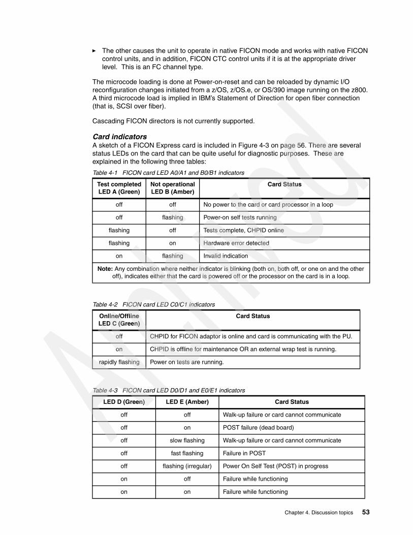
� The other causes the unit to operate in native FICON mode and works with native FICON control units, and in addition, FICON CTC control units if it is at the appropriate driver level. This is an FC channel type.
The microcode loading is done at Power-on-reset and can be reloaded by dynamic I/O reconfiguration changes initiated from a z/OS, z/OS.e, or OS/390 image running on the z800. A third microcode load is implied in IBM’s Statement of Direction for open fiber connection (that is, SCSI over fiber).
Cascading FICON directors is not currently supported.
Card indicatorsA sketch of a FICON Express card is included in Figure 4-3 on page 56. There are several status LEDs on the card that can be quite useful for diagnostic purposes. These are explained in the following three tables:
Table 4-1 FICON card LED A0/A1 and B0/B1 indicators
Table 4-2 FICON card LED C0/C1 indicators
Table 4-3 FICON card LED D0/D1 and E0/E1 indicators
Test completedLED A (Green)
Not operationalLED B (Amber)
Card Status
off off No power to the card or card processor in a loop
off flashing Power-on self tests running
flashing off Tests complete, CHPID online
flashing on Hardware error detected
on flashing Invalid indication
Note: Any combination where neither indicator is blinking (both on, both off, or one on and the other off), indicates either that the card is powered off or the processor on the card is in a loop.
Online/Offline LED C (Green)
Card Status
off CHPID for FICON adaptor is online and card is communicating with the PU.
on CHPID is offline for maintenance OR an external wrap test is running.
rapidly flashing Power on tests are running.
LED D (Green) LED E (Amber) Card Status
off off Walk-up failure or card cannot communicate
off on POST failure (dead board)
off slow flashing Walk-up failure or card cannot communicate
off fast flashing Failure in POST
off flashing (irregular) Power On Self Test (POST) in progress
on off Failure while functioning
on on Failure while functioning
Chapter 4. Discussion topics 53

4.3.1 FICON CTCBoth z800 and z900 systems support FICON channel-to-channel (CTC) connections. This has several important characteristics compared with ESCON CTC:
� A given FICON channel can be used for both CTC and normal I/O connections, whereas an ESCON channel must be used one way or the other. A FICON channel can multiplex CTC traffic along with other traffic. An ESCON channel cannot do this.
� A FICON CTC connection involving z800 and/or z900 systems will automatically determine which “side” of the connection will perform the CTC function.
� Any two LPARs, in the same system, can establish a FICON CTC connection using only a single FICON channel. This single channel must be connected to a FICON director. This is illustrated in the bottom of Figure 4-2 on page 55.
� More FICON CTC devices can be defined for a FICON channel. Up to 16K CTC devices can be defined for an FC channel, whereas the number of CTC devices defined for an ESCON CTC channel is limited to 120.
� One end of a FICON CTC link must be a z800 or z900 system9, because only one of these machines has the ability to perform FICON CTC control unit function. The other end can be either a zSeries machine10 or a G5/G6 9672 system.11
The early z800 system we used while writing this redbook did not have FICON CTC available for use. We included FICON CTC definitions in some of our IOCDS definitions, although we did not acutally use it.
on slow flashing Normal - inactive
on flashing (irregular) Normal - active
on fast flashing Normal - busy
slow flashing off Normal - link is down or not yet started
slow flashing on Not defined
slow flashing slow flashing Offline for download
slow flashing fast flashing Restricted offline mode (waiting for restart)
slow flashing flashing (irregular) Restricted offline mode, test active
fast flashing off Debug monitor in restricted mode
fast flashing on Not defined
fast flashing slow flashing Debug monitor in test fixture mode
fast flashing fast flashing Debug monitor in remote debug mode
fast flashing flashing (irregular) Debug monitor output active
LED D (Green) LED E (Amber) Card Status
9 For a z900 system to perform FICON CTC control unit function, the system must be at driver 3C level or later.10 To have a FICON CTC connection to a zSeries which has FICON CTC CU function, EC J10656 or later is required. 11 EC J10657 or later is required. A G5/G6 9672 system cannot perform the FICON CTC CU function, even if the EC is applied.
54 Technical Introduction: IBM zSeries 800

Figure 4-2 FICON CTC links in director
In the upper part of Figure 4-2, two FICON native (FC) channels in z800 are shared among LPAR1, LPAR2, and LPAR3, and communicate with LPAR4, LPAR5, and LPAR6 on another processor. Also, for communication between any two of the LPARs in the z800, both FICON channels are used to form a CTC loop back in the FICON Director. The same FICON channels can also communicate with I/O devices (CUs) attached to the Director.
The bottom half of Figure 4-2 illustrates that a single FICON channel can be looped in a Director, to form a CTC link between two LPARs in the same system. The same channel can also communicate with other systems or control units.
FC FC
zSeries 800
MIF
LPAR1 LPAR2 LPAR3
FC FC
zSeries, 9672 G5/G6*
MIF
LPAR4 LPAR5 LPAR6
CU
FICON Director
FICON CTC with 2 paths
*Note: 9672 G5/G6 cannot have FICON CTC CU function, thus loop back FICON CTC cannot be used.
FC
zSeries 800
MIF
LPAR1 LPAR2 LPAR3
CU
FC
zSeries, 9672 G5/G6*
MIF
LPAR1 LPAR2 LPAR3
*Note: 9672 G5/G6 cannot have FICON CTC CU function, thus loop back FICON CTC cannot be used.
FICON Director
FICON CTC with single path
Chapter 4. Discussion topics 55

When a FICON channel connects to a FICON channel, to form a CTC function, the channels will automatically determine which “end” will perform the CTC operation. At least one of the “ends” of such a connection must be a z800 or z900 machine.
4.4 OSA-Express adaptersThe OSA-Express adapters available for the z800 are exactly the same as for the z900. The older OSA-2 adapters available on a z900 are not available on a z800.12 The newly announced fast token ring card is available. A maximum of 12 cards per system may be used. Each card provides two ports, and each port requires a CHPID. This differs from the earlier OSA-2 adapters, where one CHPID was used by the adapter and three more were blocked. No CHPIDs are blocked by OSA-Express cards.
The OSA-Express adapters can generally run at line speeds. This was not the case for earlier LAN interfaces, and is a major improvement in capability. It has been common practice to use ESCON channels to connect to external LAN routers in order to reach the nominal line speeds for LAN connections. With the OSA Express cards, this is no longer required, providing a number of advantages:
� ESCON-attached routers are expensive. Eliminating them provides a direct savings.
� External routers can be complex and often require unique personnel training (or contract services). Eliminating them can remove the need for an expensive skill, and remove a potential failure point in your system.
� External routers can require another level of IP routing. Eliminating this simplifies your logical routing structure.
Note that the fast Ethernet and token ring ports connect to copper cables, while the gigabit Ethernet ports connect to fiber cables.
Figure 4-3 Indicators on FICON Express and OSA Express cards
12 These are located in the compatibility I/O cage of a z900. This I/O cage is not available for the z800.
E0D0
A0 B0
C0
A1 B1
C1
D1E1
A0 B0
C0
D0E0F0
A1 B1
C1
D1 E1 F1
A0 B0
C0
D0 E0
A1 B1
C1
D1 E1
A0 B0
C0
D0E0
A1 B1
C1
D1 E1
A0 B0
C0
D0E0
F0G0
A1 B1
C1
D1 E1
F1 G1
FICON TokenFast E GbE ATM
56 Technical Introduction: IBM zSeries 800

Common OSA Express card indicatorsFigure 4-3 on page 56 illustrates the indicators present on the OSA Express cards. The A, B, and C status LEDs are common to all OSA Express adapters and have the following meanings:
Table 4-4 OSA Express cards LED A0/A1 and B0/B1 indicators
Table 4-5 OSA Express cards LED C0/C1 indicator
4.4.1 Fast EthernetThe OSA Express Fast Ethernet card uses traditional copper wiring with an RJ-45 connector (see Figure 4-4 on page 58). The ports provide 10 or 100 Mbps Ethernet, with auto-negotiation of the speed used. A QDIO interface13 may be used for TCP/IP. A non-QDIO interface may be used for SNA (including APPN and HPR) and TCP/IP. This card is feature code 2366. By default, the adapter automatically adapts to 10 or 100 Mbps operation, and to half or full duplex operation. You can set these options (to avoid the automatic selection) using Support Element panels or the OSA/SF programs. Automatic operation can be a problem when used with a very lightly-loaded network with not enough activity for the adapter to properly sense.
Test completeLED A (green)
Not operationalLED B (amber)
Card Status
off off No power or card processor looping
off flashing Diagnostics are running
flashing off Tests complete, CHPID online
flashing on Hardware error detected
LED C (green) Card Status
off CHPID is online communicating with the PU
on CHPID is offline for maintenance or an external wrap test is running
rapidly flashing Power on Tests are running
flashing CHPID online
13 This is an alternative to the standard I/O interface using SSCH commands with traditional CCWs. QDIO functions have been available for some time with the z900 machines, but may not be familiar to installations with earlier systems. QDIO protocols are especially efficient for LAN interfaces. Unique operating system code is required to use QDIO, and this support exists in z/OS.
Chapter 4. Discussion topics 57

Figure 4-4 RJ-45 connector used for Fast Ethernet and High Speed Token Ring connection
Card indicatorsIn addition to the common OSA Express status LEDs (see Table 4-4 on page 57 and Table 4-5 on page 57), there are specific Fast Ethernet card indicators. These indicators have the following meanings:
Table 4-6 Fast Ethernet card LED D0/D1, E0/E1 and F0/F1 indicators
4.4.2 Gigabit EthernetThis card is available in two versions. The LX (long wave length) version, feature code 2364, uses single mode fiber with an SC Duplex multi mode connector (see Figure 4-12 on page 83). The SX (short wave length) version (feature code 2365) uses multimode fiber with an SC Duplex multi mode connector (see Figure 4-12 on page 83). See Table 4-7 for bit rate and distances. The LX version can use multimode fiber for shorter distances if MCP conversion cables are added at each end of the multimode cable.
Table 4-7 OSA-Express GbE cabling and distance
LED D (amber) LED E (green) LED F (green) Card Status
on Sending or receiving Data
off Idle - no data flow
on Operating at 100 Mbps
off Operating at 10 Mbps
on Operating in full duplex
off Operating in half duplex
Fiber Connector Bit Rate Fiber Bandwidth Max Distance
MM 62.5 micron 1000BaseSX
SC Duplex 1 Gb/s 160 MHz-km200 Mhz-km
220 meters275 meters
MM 50 micron 1000BaseSX
SC Duplex 1 Gb/s 500 Mhz-km 550 meters
SM 1000BaseLX SC Duplex 1 Gb/s n/a 5 Km
MM w/MCP 62.5 micron 1000BaseLX
SC Duplex or ESCON
1 Gb/s 500 MHz-km 550 meters
MM w/MCP50 micron 1000BaseLX
SC Duplex 1 Gb/s 500 MHz-km 550 meters
58 Technical Introduction: IBM zSeries 800

This card uses only QDIO, and is used only for TCP/IP. That is, SNA is not supported through the Gigabit Ethernet card. However, Enterprise Extender support can be used to send SNA traffic over IP.14 QDIO mode on Gigabit Ethernet on OS/390 or z/OS requires Release 7 or later of Communications Server for OS/390. Gigabit Ethernet always operates in full duplex mode.
At the time of writing, TCP/IP broadcast functions are not supported when using QDIO interfaces. This restriction applies to both the Gigabit Ethernet card and the Fast Ethernet card. This restriction is subject to change and you should verify the current status with your IBM representative or business partner.
Card IndicatorsIn addition to the common OSA Express status LEDs (see Table 4-4 on page 57 and Table 4-5 on page 57) there are specific Gigabit Ethernet card indicators, which have the following meanings:
Table 4-8 Gigabit Ethernet card LED D0/D1 and E0/E1 indicators
4.4.3 High Speed Token RingThis card has two ports and each operates independently at 4, 16, or 100 Mbps. The ports automatically adjust to the correct speed using auto-sense and auto-negotiation functions. It uses traditional copper wire connections with an RJ-45 connector shown in Figure 4-4 on page 58. Each adapter port operates in either half or full duplex depending on the speed. This adapter operates in both QDIO mode (TCP/IP traffic only) and non-QDIO mode (TCP/IP and SNA, APPN, HPR). Implementing QDIO on an OSA-Express token ring card requires Release 10 (or later) of Communications Server for OS/390. QDIO mode for Token Ring on Linux requires Linux kernel V2.4 or later. This card, feature code 2367, replaces the OSA-2 card used in earlier systems and also provides the higher speed option.
Card indicatorsIn addition to the common OSA Express status LEDs (see Table 4-4 on page 57 and Table 4-5 on page 57), there are specific OSA Express Token Ring card indicators, which have the following meanings:
Table 4-9 OSA Express Token Ring card LED D0/D1 and E0/E1 indicators
14 This requires matching Enterprise Extender software at the “other end” of the connection, of course.
LED D (amber) LED E (green) Card Status
any on Link is active
on on Data activity on link
on off Error detected, hardware stopped
any flashing Internal code loaded but card disabled
LED D (amber) LED E (green) Card Status
on on Adapter reset, on until microcode loaded
off on Diagnostics failed, adapter check, fatal error
on off Adapter open and operational
off off No power, initialization in progress
Chapter 4. Discussion topics 59

4.4.4 155 ATMThere are two versions of this Asynchronous Transfer Mode card. The SM (SX) version (feature code 2362) uses single-mode fiber cables with an SC Duplex multimode connector; see Figure 4-12 on page 83. The MM (MX) version (feature code 2363) uses multimode fiber cables with an SC Duplex multimode connector; see Figure 4-12 on page 83. ATM supports two modes of operation: ATM native mode or ATM LAN Emulation mode (Ethernet or Token Ring). Each mode is mutually exclusive (the feature can be configured for only one mode at a time). ATM can emulate Ethernet or token-ring LAN connections and use TCP/IP and/or SNA (concurrently) in a passthrough mode. QDIO operation can be used only when emulating Ethernet or token ring. QDIO mode with ATM on OS/390 or z/OS requires Release 8 or later of Communications Server for OS/390. QDIO mode with ATM on Linux requires Linux kernel V2.2.16 or later. Only one emulated port is supported by kernel V2.2.16. Kernel V2.4 is required for two ATM emulated ports.
Card indicatorsIn addition to the common OSA Express status LEDs (see Table 4-4 on page 57 and Table 4-5 on page 57) there are specific ATM card indicators, which have the following meanings:
Table 4-10 ATM card LED D0/D1, E0/E1, F0/F1 and G0/G1 indicators
flashing off Adapter diagnostics ok, awaiting adapter open
on flashing Beaconing hard error
off flashing Wire fault, open failed
flashing flashing Awaiting initialization, diagnostics not yet started
LED D (amber) LED E (green) Card Status
LED D(amber)
LED E(green)
LED F(amber)
LED G(green)
Card Status
on PCI Daughter card initialization complete
off PCI Daughter card initialization failed
on Signal good on external cable
off No signal detected on external cable
on ATM port completed registration with ATM switch
off ATM port failed registration with ATM switch
off Not used, always off
60 Technical Introduction: IBM zSeries 800

4.4.5 Emulated I/O to OSA migrationUsers migrating from MP3000 systems or older S/390 machines often find OSA Express concepts to be quite different from previous LAN interface hardware. For example, OSA Express adapters combine the traditional channel (CHPID), control unit, and device concepts into a single element--the OSA Express adapter. The OSA Express adapter is a channel (type OSD or OSE), and a control unit (or the appearance of multiple control units), and multiple devices (ports). Furthermore, in some modes of operation, a single OSA Express adapter port can appear as multiple independent ports that can be used by multiple LPARs.
A full description of OSA adapters is beyond the scope of this redbook. We strongly recommend that you consult the redbook OSA-Express Implementation Guide, SG24-5948-01 or later.
A configuration program, known as OSA/SF, is sometimes needed to customize an OSA adapter. Earlier versions of this program (used with earlier versions of OSA adapters) required some effort to understand and use. The current OSA-Express adapters, when used for TCP/IP traffic, have greatly reduced the need to use OSA/SF. Also, newer versions of the OSA/SF program can be used at a workstation and provide easier-to-use GUI interfaces.
Table 4-11 LAN interface summary
4.5 MCL updatesMCLs are Microcode Loads or updates. Almost all “updates” for modern mainframes consist of microcode changes. For earlier systems, including the z900, these updates were usually applied by IBM or third-party service representatives. This was expensive and sometimes caused scheduling difficulties. A newer format of these updates are so simple to install that the term pushbutton MCL installation is fairly accurate. For the z800, either the customer or a service representative can install these MCLs.
Part of the reason for the ease of installation is a rigid checking process whereby the MCL installation tool checks for prerequisites, corequisites, required hardware levels, and so forth. This is somewhat similar to the SMP/E tool used by z/OS for software updates. The MCL process refuses to install changes if the current state of the machine is not appropriate for that change.
CHPID type SNA/APPN/HPR TCP/IP OSA/SF needed
Gigabit Ethernet OSD (QDIO) No Yes No
Fast Ethernet OSD (QDIO)OSE (non-QDIO)
NoYes
YesYes
NoYes
Token Ring OSD (QDIO) OSE (non-QDIO)
NoYes
YesYes
NoYesa
a. OSA-Express Token Ring Requires OSA/SF for non-QDIO except for when it uses the defaultOAT without port sharing.
155 ATM Native OSE (non-QDIO) Yes Yes Yes
155 ATM LANE OSD (QDIO)OSE (non-QDIO)
NoYes
YesYes
YesYes
Chapter 4. Discussion topics 61

To assist z800 customers in installation of internal code changes, IBM Resource Link can be used to evaluate the Microcode Load (MCL) activation levels of your Hardware Management Console and Support Element. If the code levels found are too low, Resource Link will send an e-mail notification to the customer. IBM will also assist the customer with notification of HIPer MCLs. HIPer MCLs are internal code changes which prevent unscheduled incidents or data integrity problems. The customer uses the Single Step Internal Code Changes tasks to manage internal code.
The following is a general description of a pushbutton MCL installation. All steps are performed at the Hardware Management Console. Notice that there is a distinction between MCLs for an HMC and MCLs for a SE.
To update SE code (which includes all the microcode for the z800), the process is started by selecting one or more CPC icons (on the HMC screen) and then selecting the Single Step Internal Code Changes icon under Change Management, as shown in Figure 4-5 on page 62.
Figure 4-5 Single Step Internal Code Changes for SE
An update solely for the Hardware Management Console can be invoked by selecting Single Step Console Internal Code Changes from Console Actions, as shown in Figure 4-6. This installs and activates internal code changes only for the HMC you are using.
62 Technical Introduction: IBM zSeries 800
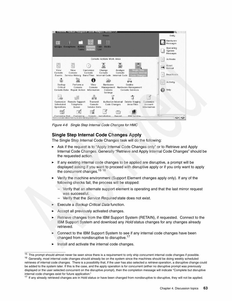
Figure 4-6 Single Step Internal Code Changes for HMC
Single Step Internal Code Changes ApplyThe Single Step Internal Code Changes task will do the following:
� Ask if the request is to “Apply Internal Code Changes only” or to Retrieve and Apply Internal Code Changes. Generally “Retrieve and Apply Internal Code Changes” should be the requested action.
� If any existing internal code changes to be applied are disruptive, a prompt will be displayed asking if you want to proceed with disruptive apply or if you only want to apply the concurrent changes.15 16
� Verify the machine environment (Support Element changes apply only). If any of the following checks fail, the process will be stopped:
– Verify that an alternate support element is operating and that the last mirror request was successful.
– Verify that the Service Required state does not exist.
� Execute a Backup Critical Data function.
� Accept all previously activated changes.
� Retrieve changes from the IBM Support System (RETAIN), if requested. Connect to the IBM Support System and download any Hold status changes for any changes already retrieved.
� Connect to the IBM Support System to see if any internal code changes have been changed from nondisruptive to disruptive.17
� Install and activate the internal code changes.
15 This prompt should almost never be seen since there is a requirement to only ship concurrent internal code changes if possible.16 Generally, most internal code changes should already be on the system since the machines should be doing weekly scheduled retrieves of internal code changes. There is a possibility that, if the user has also selected a retrieve operation, a disruptive change could be added to the system later. If this is the case, and the apply operation is for concurrent (either no disruptive prompt was previously displayed or the user selected concurrent on the disruptive prompt), then the completion message will indicate “Complete but disruptive internal code changes exist for future application.”17 If any already retrieved changes are in Hold status or have been changed from nondisruptive to disruptive, they will not be applied.
Chapter 4. Discussion topics 63

� For Support Element internal code changes, start an alternate support element mirroring operation.
Single Step Internal Code Changes RemoveThe reverse function called Single Step Internal Code Changes Remove is also provided. This will do the following:
� If any internal code changes to be removed are disruptive, a prompt will be displayed asking if you want to proceed with disruptive remove or if you only want to remove the concurrent changes.18
� Verify the machine environment (for removing support element changes only). If any of the following checks fail, the process will be stopped.
– Verify that the alternate support element is operating and that the last automatic mirror request was successful.
– Verify that Service Required state does not exist.
� The selected internal code changes will be removed then activated to the accepted internal code levels.
� Finally, if Support Element changes are involved, an alternate Support Element mirroring operation will be started.
The following is a list of the possible messages that may be displayed during these processes.
Initiating Single Step Internal Code Changes ApplyInitiating Single Step Internal Code Changes RemoveVerifying System EnvironmentBacking up Critical Hard Disk InformationAccepting Installed Changes that were activatedRetrieving Internal Code ChangesDownloading Internal Code Changes status updatesInstalling and Activating Internal Code ChangesRemoving and Activating Internal Code ChangesMirroring Data to Alternate Support ElementCompletedFailedCompleted-Disruptive changes were not appliedCancelled by user
4.5.1 Running Single Step Internal Code Changes as a scheduled operationThe internal code changes task may be initiated as a scheduled operation for both the HMC and the Support Element/CPC. For Support Element/CPC changes only concurrent changes can be applied. Disruptive internal code changes must be applied manually.
4.6 IOCDSAn IOCDS (I/O Configuration Data Set) is a (binary) file used by the I/O subsystem in S/390 and z/Architecture systems. It is created from IOCP (I/O Configuration Program) source control statements. The IOCP statements may be created directly, using an ASCII editor on a PC, or embedded in definitions created by the HCD (Hardware Configuration Definition) utility of z/OS. One can debate whether we should use the term IOCP definitions or IOCDS
18 This prompt should almost never be seen since there is a requirement to only ship concurrent internal code changes if possible.
64 Technical Introduction: IBM zSeries 800

definitions in the following discussions; we decided to use the IOCDS term. An IOCP (source) is compiled (by an internal Support Element function or HCD function) to create an IOCDS (binary). The IOCP source and IOCDS reflect the same information, just in different forms.
An IOCDS performs a number of tasks:
� It defines the paths involved in accessing each I/O device. For example, it can define multiple paths (via different CHPIDs) to a control unit. It can define paths through an ESCON Director (switch) for control units.
� It defines the device number (or software address) seen by the operating system for various I/O devices. The hardware paths to a device (via CHPIDs, channels, directors, control units and device unit addresses) can be completely hidden by an arbitrary software address. Stated another way, a single, simple software address (for example, the disk at address 0A80) can represent a complex set of paths that the system hardware (the I/O subsystem) can use to access the device.
� It defines the name and number for each LPAR if you intend to use LPAR mode. Note that the resources for each LPAR, such as the number of logical CP/IFL/ICFs, the size of memory, and so on, are defined in an image profile (not in an IOCDS) which has the same name as the LPAR name.
� It defines how various I/O resources are related to different LPARs if it is for LPAR mode. Some devices may be seen by multiple LPARs and others seen by only a single LPAR. The device number (software address) of a given device can be the same for several LPARs or defined differently for each LPAR.
IOCDS concepts are familiar to owners of all recent S/390 systems. They may not be familiar to new z800 customers. A z800 (or any other zSeries or S/390 systems) must have an active IOCDS before it can start any operating system, including Linux. z/OS (and OS/390) have utility functions to help create an appropriate IOCDS. Linux has no equivalent function. An IOCDS that can be used for Linux might be created under z/OS (if present), or created by a stand-alone process.
The z800 IOCDS concepts are exactly the same as the z900 and all recent S/390 machines (including the MP3000). Installations with existing S/390 or z900 machines can use existing IOCDS definitions, if appropriate.19
A significant portion of z800 systems are expected to go to installations without much S/390 or z900 experience. For these customers, the IOCDS functions may be confusing initially; we provide a brief introduction here.
A z800 has four IOCDS “slots”, named A0, A1, A2, and A3, to store different I/O configurations. You can switch which IOCDS is used by performing a Power On Reset (POR) function, which causes the entire z800 system be reset. You might have some of your IOCDs in basic mode (no LPARs) and some in LPAR mode. A POR is required to change these modes (as well as changing the IOCDS that is to be used).
Appendix A, “Listings” on page 137 contains the IOCDSs we used while writing this redbook.
4.6.1 IOCP statementsThe following are the statements (or “macros”) for IOCP, with brief descriptions.
ID This statement must be the first statement in the IOCP source input. There are four parameters for ID statement: MSG1, MSG2, SYSTEM, and TOK.
19 There are reasonable restrictions on this. For example, an MP3000 IOCDS defining emulated I/O or internal DASD cannot be used because this hardware does not exist on a z800 machine.
Chapter 4. Discussion topics 65

Character strings up to 64 bytes can be specified for both MSG1 and MSG2 parameters. The first eight characters of MSG1 appears as the IOCDS name in the Input/Output Configuration panel on the Support Element (SE). The SYSTEM parameter is to specify the machine type, and IOCP validates this definition. “SYSTEM=(2066,1)” is for z800 general or Linux-only models, and “SYSTEM=(2066,2)” is for z800 CF only models. The TOK parameter is used for an HSA token and this is used for z/OS HCD dynamic I/O reconfiguration; you may omit this.20
RESOURCE This statement is normally used only for LPAR mode, and defines all the LPAR names (and numbers). The partition number is important for some control unit definitions, such as for ESCON/FICON CTCs, 2074 terminal controllers. Note that 0 cannot be defined as a partition number.
CHPID This statement defines a channel21 and specifies the channel type, whether it is shared or dedicated, which LPARs are allowed to use it, and whether it is connected directly to the device or via an ESCON/FICON director. We discuss channel types later.
CNTLUNIT This statement defines “logical” control unit hardware. We say “logical” here because some control units, such as an IBM Enterprise Storage Server (ESS), need multiple control unit definitions, although there is only one physical control unit. You should refer to each control unit’s reference material to see how to define it in IOCP statements.
IODEVICE This statement defines a device number, which represents a device for the operating system. Generally, only these device numbers are visible from the operating system.
See the latest version of e(logo)server zSeries 800 and 900 Input/Output Configuration Program User’s Guide for IYP IOCP, SB10-7029 for further details on each IOCP statement.
4.6.2 Channel definitions in the IOCP statementThe following channel types (as defined in an IOCDS) are used with z800 systems:
� FICON channel types
– FC - Native FICON channel (both for native FICON devices and FICON CTCs)– FCV - FICON bridge channel– (FCP - in the future, if Open FCP is implemented as outlined in the IBM statement of
direction.)
� ESCON channel types
– CNC - Native ESCON channel– CTC - ESCON CTC channel– CVC - ES conversion channel, which connects to a converter in block multiplexer mode– CBY - ES conversion channel, which connects to a converter in byte multiplexer mode
� CF link channel types
– CBP - Integrated Coupling Bus (ICB-3) channel, for both OS and CF partitions, to connect between zSeries machines
– CFP - InterSystem Coupling (ISC-3) peer mode channel, for both OS and CF partitions– CFS - ISC-3 compatibility mode sender channel, for OS partitions22
– CFR - ISC-3 compatibility mode receiver channel, each must be used for only 1 CF partition
20 Only an IOCDS created from IOCP statements generated by HCD is allowed to change hardware configuration from an operating system (z/OS or OS/390) image.21 Remember that “channel” is a general concept. For example, OSA Express ports are considered channels.22 When you use z/OS system-managed CF duplexing, 1 CF partition can be additionally share the CF sender channel.
66 Technical Introduction: IBM zSeries 800

– ICP - Peer mode Internal Coupling (IC-3) channel, for both OS and CF partitions, to connect among LPARs within a z800 system internally
� OSA-Express channel types
– OSD - OSA-Express (QDIO)– OSE - OSA-Express (LCS)
� HiperSockets channel type
– IQD - HiperSockets channel, QDIO mode only
Each of these channel types requires that a CHPID be defined, even if it is an internal channel and no physical hardware (channel card) exists. For example, each IC-3 link or HiperSockets channel occupies a CHPID within the range of hexadecimal 00 to FF. Each channel, whether a “real” channel device or a virtual device (such as a HiperSocket) must be assigned a unique CHPID. The default CHPID addresses (for real channel devices) are always assigned starting with address 00 and working upward. We suggest you assign your virtual devices (such as HiperSockets and IC links) starting at address FF and working downward.
Most of these channel types can be shared and used concurrently among multiple LPARs. This capability is known as the Multiple Image Facility (MIF). Exceptions are for ES conversion channels (CVC and CBY) and CF receiver channels (CFR). These channel types cannot be shared concurrently, but can be defined as reconfigurable channels by specifying the REC parameter on the channel definition. The channel can be reassigned to another LPAR after the former owning LPAR configures the channel offline.
There are no parallel channels or ICB-2 channels provided for z800 systems. Channel types D/S/S4 and CBS/CBR cannot be defined.
4.6.3 Building an IOCDS from an IOCP source input fileIf you are familiar with z/OS, OS/390, or z/VM, you may prefer to create the IOCDS from one of those operating systems. If you do not have one of these operating systems installed (or are installing the first one), you may need to create and install an IOCDS in stand-alone mode. The following is a brief description of the process:
7. Log onto the HMC or SE as SYSPROG.
8. If you are using the SE, skip ahead to step (7); if you are using HMC, follow with the next step. (If you are not fully comfortable with HMC operations, we suggest you initially use the SE for these steps.)
9. Find the CPC Recovery task list on the HMC
Chapter 4. Discussion topics 67
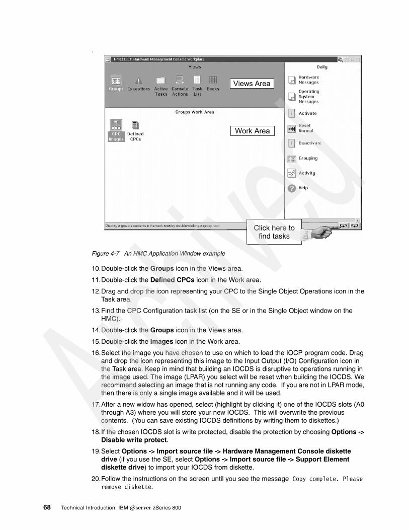
.
Figure 4-7 An HMC Application Window example
10.Double-click the Groups icon in the Views area.
11.Double-click the Defined CPCs icon in the Work area.
12.Drag and drop the icon representing your CPC to the Single Object Operations icon in the Task area.
13.Find the CPC Configuration task list (on the SE or in the Single Object window on the HMC).
14.Double-click the Groups icon in the Views area.
15.Double-click the Images icon in the Work area.
16.Select the image you have chosen to use on which to load the IOCP program code. Drag and drop the icon representing this image to the Input Output (I/O) Configuration icon in the Task area. Keep in mind that building an IOCDS is disruptive to operations running in the image used. The image (LPAR) you select will be reset when building the IOCDS. We recommend selecting an image that is not running any code. If you are not in LPAR mode, then there is only a single image available and it will be used.
17.After a new widow has opened, select (highlight by clicking it) one of the IOCDS slots (A0 through A3) where you will store your new IOCDS. This will overwrite the previous contents. (You can save existing IOCDS definitions by writing them to diskettes.)
18.If the chosen IOCDS slot is write protected, disable the protection by choosing Options -> Disable write protect.
19.Select Options -> Import source file -> Hardware Management Console diskette drive (if you use the SE, select Options -> Import source file -> Support Element diskette drive) to import your IOCDS from diskette.
20.Follow the instructions on the screen until you see the message Copy complete. Please remove diskette.
Views Area
Work Area
Click here to find tasks
68 Technical Introduction: IBM zSeries 800

21.Select Options -> Build data set. If you are building the data set for logically partitioned mode, do not forget to check the relevant check box in the pop-up window.
22.Wait for the Processing completed message.
23.If errors in the input file are found, you may correct them on the spot using a simple editor built into the SE function you are using. Each error message is written into the input file just below the statement where the error was found. Select Options -> Open source file, edit and save the file, then rebuild the data set.
If you installed an IOCDS that uses LPARs, verify that appropriate activation profiles exist for the required LPARs. To use your new IOCDS, perform a Power-on-reset (POR) function. If your IOCDS is for basic mode, you can simply use the POR icon. If your IOCDS is for LPAR mode, you need to use the ACTIVATE icon (assuming you have defined your profiles for your new environment).
4.7 IBM 2074 setupTraditional S/390 operating systems (meaning everything except Linux) use 3270 terminals for customization, operation, and a basic user interface. For practical purposes you need locally-attached, non-SNA 3270 connections for operator consoles and initial TSO sessions. Using these TSO sessions you can further customize the system for connection to SNA networks and TCP/IP networks. You can connect 3270 sessions two ways: through an IBM 3174 control unit or through an IBM 2074 control unit. The 3174 is no longer manufactured, although many are in use in existing S/390 installations. The 2074 is currently manufactured and marketed.
The 3174 control unit connects to “real” 3270 terminals, via coax cable. The 2074 connects to TN3270e clients, via LANs. The 2074 converts the TN3270e sessions such that they appear to originate in a locally-attached 3174 connected to “real” 3270 terminals. See the redbook Introducing the IBM 2074 Control Unit , SG24-5966 for more details.
Our very minimal 2074 setup, used while producing this redbook, is sketched in Figure 4-8 on page 70. Our other LAN connections are included for completeness.23 The 2074 is connected to the z800 with an ESCON channel. (The 2074 can have up to two ESCON channel connections.) The 2074 provides two emulated (TN3270e) sessions on its own console and four LAN connections (two Ethernet and two token ring) to connect to clients having additional TN3270e sessions. We used one token ring LAN for this purpose and connected it to two client PCs. These were using IBM’s PCOM product24 as the TN3270E clients.
We also connected two z800 Fast Ethernet ports to Ethernet hubs and then connected these to the same PCs. The PCOM emulator can support multiple TN3270e sessions. Our somewhat peculiar arrangement permitted us to selectively work with QDIO and/or LCS connections to z/OS TCP/IP and Linux.
23 The LAN connection from our Support Elements to the HMC is not shown. It is a separate token ring LAN with no external connections.24 The full product name is eNetwork Personal Communications.
Chapter 4. Discussion topics 69

Figure 4-8 ITSO 2074 and LAN connections
The 2074 is configured through a GUI interface. Two key panels are the Device Configuration panel (accessed through F2) and the LAN Environment panel (accessed through F4). Our input for these panels is shown here. Your requirements will almost certainly differ, but our configuration may serve to organize your ideas. Our F2 panel, sometimes known as the DEVMAP (named after a similar panel in P/390 and MP3000 systems), contained the following:
Index Device LPAR# Port CU UA Mgr Parm.............. 01 3278 1 01 0 00 1 Local 02 3278 1 01 0 01 1 Local 03 3278 2 01 1 00 2 /R=ADOP 03 3278 2 01 1 01 2 /R=ADTSO 03 3278 5 01 5 00 2 /R=ZAD1OP 03 3278 5 01 5 01 2 /R=ZAD1TSO 03 3278 6 01 6 00 2 /R=ZAD2OP 03 3278 6 01 6 01 2 /R=ZAD2TSO 03 3278 7 01 7 00 2 /R=ZOSEOP 03 3278 7 01 7 01 2 /R=ZOSETSO
This configuration gave us two 3270 sessions in each of five LPARs. The LPAR numbers shown must match the LPAR numbers in the active IOCDS. A separate control unit address (CU) is used for each LPAR and, within each CU, two unit addresses (UA) are specified. The Port number must be 01 if the 2074 is directly connected to an ESCON channel. (The Port number is relevant when connected through an ESCON Director.) The Mgr parameter is 1 for the two TN3270e sessions that appear on the 2074 display, and 2 for all LAN-connected TN3270e sessions.
The /R parameter specifies an LU name. The LU parameter was originally designed for SNA configurations, but is used for another purpose here and is unrelated to SNA usage. A TN3270e client can specify an LU name for each session. A client LU name that matches one of the specified 2074 LU names will permit a connection to that session. For example, if a client TN3270e session (connected to the appropriate LAN and using the IP address of the 2074) specifies LU name ZAD2OP, it will be connected to the operating system in LPAR 6. The LU name lets the client user specify which LPAR (and perhaps which subsystem in the operating system) he wishes to use.
We specified our 2074 LAN environment (F4) as follows:
LAN0(ETHER) IPaddress>0.0.0.0 Mask>255.255.255.0 Enabled?(y/n)>n Parms> metric 1 mtu 1500
z800
ESCON
Enet (QDIO)
Enet (LCS)
hub
hub
MAU2074
clientPC
clientPC
tr
tr
tr
En
En
local TN3270sessions
En = Enet = Ethernettr = token ring
70 Technical Introduction: IBM zSeries 800

LAN1(ETHER) IPaddress>10.10.1.1 Mask>255.255.255.0 Enabled?(y/n)>n Parms> metric 1 mtu 1500
LAN2(TOKEN) IPaddress>10.10.2.1 Mask>255.255.255.0 Enabled?(y/n)>y Parms> metric 1 mtu 1500
LAN3(TOKEN) IPaddress>10.10.3.1 Mask>255.255.255.0 Enabled?(y/n)>n Parms> metric 1 mtu 1500
With these parameters, our single token ring LAN interface to the 2074 was addressed as 10.10.2.1. By default, the IP port address of the 2074 is port 3270; we did not change this.
Several of our IOCDSs are listed in Appendix A, “Listings” on page 137. Some of the parameters relevant to the 2074, extracted from one of the IOCDS listings, are:
...CHPID PATH=(04),TYPE=CNC,SHARED...CNTLUNIT CUNUMBR=9400,PATH=(04),UNITADD=((00,32)),CUADD=0, X UNIT=3174IODEVICE ADDRESS=0A1,MODEL=3X,UNITADD=0,CUNUMBR=(9400), X STADET=Y,UNIT=3279,PARTITION=(ZOSE0001)IODEVICE ADDRESS=(F00,003),MODEL=3X,UNITADD=01,CUNUMBR=(9400), X STADET=Y,UNIT=3279,PARTITION=(ZOSE0001)....CNTLUNIT CUNUMBR=9401,PATH=(04),UNITADD=(00,08)),CUADD=1, X UNIT=3174IODEVICE ADDRESS=(700,08),MODEL=X,UNITADD=00,CUNUMBR=(9401), X STADET=Y,UNIT=3279,PARTITION=(ADSYSTEM)...
As shown in this IOCDS extract, the 2074 emulates a 3174 (or multiple 3174s). In our system it was connected to CHPID 4.
Assume LPAR name ZOSE0001 corresponds to LPAR 1 and ADSYSTEM corresponds to LPAR 2. A client connected to 10.10.2.1 port 3270 using LU name ADTSO would connect to LPAR 2 as address 701. You should be able to follow this connection logic using the DEVMAP and IOCDS extracts listed above.
The IBM 2074 is a very flexible device and this flexibility can be confusing initially. We recommend the redbook mentioned earlier, Introducing the IBM 2074 Control Unit, SG24-5966, for more complete information.
4.8 Integrated Facility for LinuxAn IFL, or Integrated Facility for Linux, provides additional processing capacity exclusively for Linux workloads. An IFL is feature code 3700, and a maximum quantity of three may be ordered for a general purpose z800.25 Traditional S/390 software charges are typically not affected by the additional IFL processing capacity.26 A processing unit (PU) enabled for IFL work is often referred to as an IFL engine. There are several characteristics of an IFL processing unit or engine:
� It must be used in one or more LPARs; it cannot be used in basic mode.
25 A Linux-only model, the 2066-0FL, uses feature codes 3601 - 3604 to specify up to four IFL PUs.26 This is a simple statement for a very complex topic and may not always be true. In general, most IBM software costs are not affected by the addition of IFL processors. Other software vendors may have different policies. For software prices that are tied to system model numbers, the statement is usually true because the addition of IFLs does not change the model number of the system.
Chapter 4. Discussion topics 71
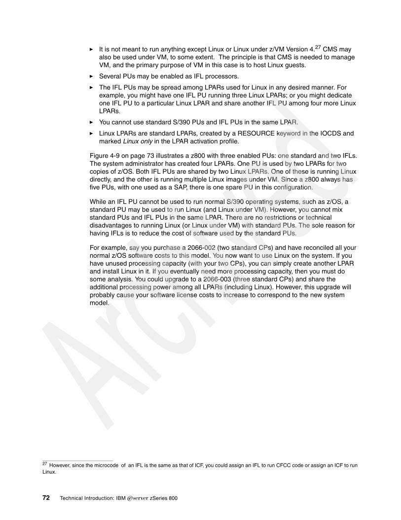
� It is not meant to run anything except Linux or Linux under z/VM Version 4.27 CMS may also be used under VM, to some extent. The principle is that CMS is needed to manage VM, and the primary purpose of VM in this case is to host Linux guests.
� Several PUs may be enabled as IFL processors.
� The IFL PUs may be spread among LPARs used for Linux in any desired manner. For example, you might have one IFL PU running three Linux LPARs; or you might dedicate one IFL PU to a particular Linux LPAR and share another IFL PU among four more Linux LPARs.
� You cannot use standard S/390 PUs and IFL PUs in the same LPAR.
� Linux LPARs are standard LPARs, created by a RESOURCE keyword in the IOCDS and marked Linux only in the LPAR activation profile.
Figure 4-9 on page 73 illustrates a z800 with three enabled PUs: one standard and two IFLs. The system administrator has created four LPARs. One PU is used by two LPARs for two copies of z/OS. Both IFL PUs are shared by two Linux LPARs. One of these is running Linux directly, and the other is running multiple Linux images under VM. Since a z800 always has five PUs, with one used as a SAP, there is one spare PU in this configuration.
While an IFL PU cannot be used to run normal S/390 operating systems, such as z/OS, a standard PU may be used to run Linux (and Linux under VM). However, you cannot mix standard PUs and IFL PUs in the same LPAR. There are no restrictions or technical disadvantages to running Linux (or Linux under VM) with standard PUs. The sole reason for having IFLs is to reduce the cost of software used by the standard PUs.
For example, say you purchase a 2066-002 (two standard CPs) and have reconciled all your normal z/OS software costs to this model. You now want to use Linux on the system. If you have unused processing capacity (with your two CPs), you can simply create another LPAR and install Linux in it. If you eventually need more processing capacity, then you must do some analysis. You could upgrade to a 2066-003 (three standard CPs) and share the additional processing power among all LPARs (including Linux). However, this upgrade will probably cause your software license costs to increase to correspond to the new system model.
27 However, since the microcode of an IFL is the same as that of ICF, you could assign an IFL to run CFCC code or assign an ICF to run Linux.
72 Technical Introduction: IBM zSeries 800

Figure 4-9 Separation of standard and IFL PUs
The alternative is to keep your 2066-002 model and add an IFL feature. This will increase your processor capacity, but only for Linux work. You would probably offload Linux work from your standard CPs by moving it to the IFL PU, but this is not required. You could, if your situation made it reasonable, run a Linux LPAR with your standard CPs, and other Linux LPARs with your IFL PUs. The only restriction is that you cannot have standard CPs and IFL PUs in the same LPAR.
4.8.1 Adding an IFLThe addition of an IFL engine is not disruptive. However, bringing the IFL into a Linux partition can be. Planning will need to be done ahead of time in order to activate the Linux LPAR nondisruptively. In order to use the IFL without a POR, certain conditions must exist:
� The last POR was done in LPAR mode.
� The Linux partition was defined in the IOCDS used at the last POR.
� Resources can be made available to activate the Linux partition without having to POR the machine or having to deactivate another partition.
If the Linux LPAR is already running, but is using a CP instead of an IFL, the partition must be deactivated, redefined in its Image Profile to use the IFL, and reactivated. This can all be done via the HMC, but it is disruptive to the Linux partition. When defining an LPAR image profile to use an IFL, the choices in the Image Profile28 are CP or ICF; you must select ICF at this point in order to use an IFL. This is because the PR/SM hipervisor treats ICFs and IFLs as the same. The ICF choice will not appear unless an IFL (or an ICF) is present on the machine and the partition type is selected to be Linux Only (for Linux or under z/VM 4.2).
standard PU IFL PU IFL PUspare PU
z/OS z/OS
z/VM
LinuxLinux
Linux
Linux
Linux
LPAR 1 LPAR 2 LPAR 3 LPAR 4
. . . . . . . . . . . . . . . . . . . . . . . . z800 system . . . . . . . . . . . . . . . . . . . . . . . . . .
CMS
28 The Image Profile is a series of GUI panels that is are used to define activation profiles for LPARs. These panels can be accessed through the SE or HMC.
Chapter 4. Discussion topics 73

4.9 LPAR setup and examplesThis section is intended for readers who are unfamiliar with the process of defining (“creating”) LPARs on a z800 or z900. It is a brief walkthrough of the basic steps that can be followed to set up an LPAR. For this example, we worked with a z800 model that had three normal CPs and one IFL. Our example defines two Linux LPARs that use only the IFL.29 Setting up LPARs involves the following steps:
� Defining resources via an IOCDS� Building an IOCDS� Defining resources via RESET and IMAGE profiles� Activating changes
If possible, we suggest working at the HMC or SE while reading this section. We also recommend having an IOCDS file ready on diskette before you start. You can create such a file manually using an HCD/SE editor, or any editor able to save text in a plain ASCII text file.
A full listing of the IOCDS file used in our examples can be found in “IOCDS for Linux (two partitions)” on page 139.
Step 1. Defining resources via IOCDSThe definitions are created in a plain text file. You can find additional information on the contents of IOCDS source files in 4.6, “IOCDS” on page 64. In our sample definition we define the following resources:
1. Logical partitions
The IOCDS name is LINXONLY and we define two LPARs named LINUX 1 and LINUX2.
ID MSG1='LINXONLY',SYSTEM=(2066,1) RESOURCE PARTITION=((LINUX1,1),(LINUX2,2))
2. Channels
Two channels are used for network devices. Channel 02 is dedicated to the LINUX1 partition only, and channel 03 is shared between the two partitions.
CHPID PATH=(02),TYPE=OSE,PARTITION=(LINUX1) CHPID PATH=(03),TYPE=OSD,SHARED
Four channels are for access to disks. In our case these channel paths passed through a switching device (an ESCON Director).
CHPID PATH=(06),SWITCH=AA,TYPE=CNC,SHARED CHPID PATH=(07),SWITCH=BB,TYPE=CNC,SHARED CHPID PATH=(11),SWITCH=AA,TYPE=CNC,SHARED CHPID PATH=(12),SWITCH=BB,TYPE=CNC,SHARED
3. Control units and their respective devices
OSA Fast Ethernet in LCS mode is defined by the following:
CNTLUNIT CUNUMBR=E20,PATH=(02),UNIT=OSA IODEVICE ADDRESS=(E20,15),CUNUMBR=E20,UNIT=OSA,UNITADD=00 IODEVICE ADDRESS=(E2F,1),CUNUMBR=E20,UNIT=OSAD,UNITADD=FE
OSA Fast Ethernet in QDIO mode is defined by the following:
CNTLUNIT CUNUMBR=E30,PATH=(03),UNIT=OSA IODEVICE ADDRESS=(E30,15),CUNUMBR=E30,UNIT=OSA,UNITADD=00
Our disk drives30 are defined as follows:
29 This element of the example is not very realistic, since it leaves our three CPs unused.30 Note that the continuation mark (*) is placed in column 72, see Input/Output Configuration Program Users Guide for IYP IOCP, SB10-7029 for more details.
74 Technical Introduction: IBM zSeries 800

CNTLUNIT CUNUMBR=0A00,PATH=(06,12),UNITADD=((00,064)),LINK=(F3,E3), * CUADD=0,UNIT=3990 CNTLUNIT CUNUMBR=0A01,PATH=(07,11),UNITADD=((00,064)),LINK=(F3,E3), * CUADD=0,UNIT=3990 IODEVICE ADDRESS=(310,064),UNITADD=00,CUNUMBR=(0A00,0A01), * STADET=Y,UNIT=3390
Our tape drives are defined as:
CNTLUNIT CUNUMBR=0B00,PATH=(06,12),UNITADD=((00,016)),LINK=(D8,D8), * UNIT=3490 IODEVICE ADDRESS=(390,002),UNITADD=00,CUNUMBR=(0B00),STADET=Y, * UNIT=3490,PARTITION=(LINUX2)
Since Linux systems do not use 3270-type terminals, no such devices are defined in our example. Our Linux did not use tape drives either, but we defined them anyway.
Step 2. Building the IOCDSOnce the source file for the IOCDS (that is, the IOCP source file) is ready, you can import it into the HMC or the SE and build the IOCDS. The required steps are outlined in 4.6.3, “Building an IOCDS from an IOCP source input file” on page 67.
Step 3. Defining resources via RESET and IMAGE profilesHaving built the IOCDS, you then need to define a new RESET profile. This profile is to be used for POR and for activation of the whole CEC, if needed.
1. Log onto the HMC as SYSPROG.
2. Find the CPC Operational Customization task list.
3. Double-click the Groups icon in the Views area.
4. Double-click the Defined CPCs icon in the Work area.
5. Drag and drop the icon representing your CPC to the Customize/Delete Activation Profiles icon in the Task area.
6. After a new window pops up (a notebook format), select the Default Reset activation profile from the list of profiles (click it). Another new window pops up in a notebook format. This is your RESET profile edit window.
7. You may receive a message stating that the LPAR names defined in the current activation profile do not match the LPAR names in the profile you have just opened. You may ignore the message for now.
8. Change the profile name. We used the IOCDS name for simplicity (LINXONLY).
9. Select your recently built IOCDS set from the list. After you click on it, you will see the right-hand tabs of the notebook change to correspond to LPAR names defined in the IOCDS.
10.In the Mode list select Logically partitioned.
11.Click Assign to make the profile the default activation profile.
12.Now you may go on to defining image profiles. Otherwise, click Save to save the profile and exit, or continue within the current notebook window to define IMAGE profiles for your partitions.
Chapter 4. Discussion topics 75

The easiest way to define IMAGE profiles is to do it while editing the RESET profile. Click on one of the right-hand tabs representing an LPAR and fill in the data according to your installation setup. The bottom tabs allow you to move to the relevant section of the image profile quickly. The IMAGE profiles will be saved together with the RESET profile under the names of their respective partitions. Once saved, they can be edited independently of the RESET profile. If you delete an IMAGE profile, activation of the respective partition will fail.
You can also define an IMAGE profile by editing the DEFAULT IMAGE profile and saving it under the name of a respective LPAR.
Defining the RESET and IMAGE profiles is not disruptive to any tasks running on the processor.
We specified the following parameters for the IMAGE profiles of each of our Linux partitions:
1. Partition tab
Linux only mode, in the Choose mode window, because we wanted the Linuxes to run using IFLs only.
2. Processors tab
Not dedicated coupling facility processors in the Processors tab, because we did not want to dedicate our IFL to a single LPAR. IFLs and ICFs fully equivalent from the microcode point of view, hence this somewhat misleading description. Please note, that general purpose processors (CPs) and IFLs cannot be used in the same partition at the same time.
We also specified 1 as the number of Active processors (you may specify this number up to the number of currently installed CPs or IFLs/ICFs) and 0 as Reserved, since Linux has no mechanism to vary additional processors online while it is running.
3. Storage tab
We specified 128 in the Central storage in megabytes field. We did not specify any reserved storage since Linux has no mechanism to vary additional storage online while it is running.
4. Load tab
We did not specify a Load address (IPL address) or Load parameter for either Linux. We checked the Use dynamically changed load address check box to allow its use to IPL our Linux partitions from various disk packs as needed, and left the Load during activation check box empty so that an IPL was not forced in the partition during its activation. In a production environment, with stable IPL addresses and infrequent IPLs, you might want to do just the opposite, i.e., uncheck the Use dynamically changed load address check box, specify a load address, and check the Load during activation check box.
Step 4. Activating changesTo activate your new RESET profile, and thus create the LPARs, do the following:
1. Log onto the HMC as SYSPROG.2. Find the Daily task list.3. Double-click the Groups icon in the Views area.4. Double-click the Defined CPCs icon in the Work area.5. Drag and drop the icon representing your CPC to the Activate icon in the Task area.
This will activate your IOCDS with all the parameters specified in the RESET profile assigned for default activation. If you have checked the Load during activation check box in the Load tab of the IMAGE profile notebook, your respective LPARs will be IPLed with the parameters given.
76 Technical Introduction: IBM zSeries 800

To IPL the partition (if you did not check the Load during activation check box) you perform the actions described in “Step 6. IPL the new Linux system from disk” on page 47. The same procedure applies to IPLing from tape. The only parameter you change is the IPL address.
4.10 HiperSocketsHiperSockets provide high-performance “networks in a box.” A z800 has up to four internal HiperSocket LANs. Each of these uses a special internal CHPID that can be accessed by all partitions. All the connections to one of these CHPIDs are, in effect, sharing an internal LAN. Characteristics include:
� Excellent performance and response times because all operations are through the system memory bus.
� High availability because there are no external parts or connections involved.
� Cost savings, again because no external parts or connections are involved.
� General connectivity for z/OS, Linux, and z/VM, with standard or IFL PUs.
� Easy to install and operate because it works like a simple LAN.
� Up to 1,024 TCP/IP stacks may be connected (using all four HiperSockets).
� Up to 4,000 IP addresses can be used.
� No interference with system performance because HiperSocket data flow does not go through the system cache.
� Channel access is through QDIO programming.
� Multicasting is supported, but broadcasting is not supported.
� Not available to TPF systems.
HiperSockets can be configured many ways. Figure 4-10 on page 78 shows a simplistic arrangement, but illustrates key concepts. Up to four special HiperSocket CHPIDs exist, and each one is, in effect, a LAN. TCP/IP connections to each LAN are handled as normal TCP/IP connections. Notice that HiperSockets exist only within a z800 (or z900) system. There are no external connections, not even to another z800 or z900 machine. Any external connection must be through other means, such as OSA adapters, channel-to-channel connections, XCF connections, and so forth.
Chapter 4. Discussion topics 77
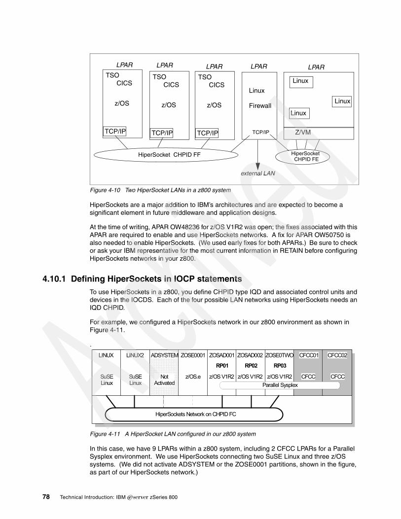
Figure 4-10 Two HiperSocket LANs in a z800 system
HiperSockets are a major addition to IBM’s architectures and are expected to become a significant element in future middleware and application designs.
At the time of writing, APAR OW48236 for z/OS V1R2 was open; the fixes associated with this APAR are required to enable and use HiperSockets networks. A fix for APAR OW50750 is also needed to enable HiperSockets. (We used early fixes for both APARs.) Be sure to check or ask your IBM representative for the most current information in RETAIN before configuring HiperSockets networks in your z800.
4.10.1 Defining HiperSockets in IOCP statementsTo use HiperSockets in a z800, you define CHPID type IQD and associated control units and devices in the IOCDS. Each of the four possible LAN networks using HiperSockets needs an IQD CHPID.
For example, we configured a HiperSockets network in our z800 environment as shown in Figure 4-11.
.
Figure 4-11 A HiperSocket LAN configured in our z800 system
In this case, we have 9 LPARs within a z800 system, including 2 CFCC LPARs for a Parallel Sysplex environment. We use HiperSockets connecting two SuSE Linux and three z/OS systems. (We did not activate ADSYSTEM or the ZOSE0001 partitions, shown in the figure, as part of our HiperSockets network.)
z/OS
TCP/IP
TSOCICS
z/OS
TCP/IP
TSOCICS
z/OS
TCP/IP
TSOCICS
Linux
Firewall
Z/VM
Linux
Linux
Linux
external LAN
HiperSocket CHPID FF HiperSocketCHPID FE
TCP/IP
LPAR LPAR LPAR LPAR LPAR
LINUX
HiperSockets Network on CHPID FC
LINUX2 ADSYSTEM ZOSE0001 ZOSAD001 CFCC02CFCC01ZOSAD002 ZOSE0TWO
SuSELinux
SuSELinux
NotActivated
z/OS.e z/OS V1R2 CFCCCFCCz/OS V1R2 z/OS V1R2Parallel Sysplex
RP01 RP02 RP03
78 Technical Introduction: IBM zSeries 800

The following is an extract of the IOCDS definitions needed for a HiperSockets network:
* ------------ START OF IOCP STATEMENTS FOR 2066 ---------------- ID MSG1='LPARTEST',SYSTEM=(2066,1) ** ------------ LPAR DEFINITIONS --------------------------------- RESOURCE PARTITION=((ZOSE0001,1),(ADSYSTEM,2),(LINUX,3),(LINUX2,4), * (ZOSAD001,5),(ZOSAD002,6),(ZOSE0TWO,7), * (CFCC01,E),(CFCC02,F)) ** ------------ HIPERSOCKETS CHPID ------------------------------- CHPID PATH=(FC),TYPE=IQD,SHARED,OS=00 ** ------------ HIPERSOCKETS CONTROL UNIT AND DEVICES ------------ CNTLUNIT CUNUMBR=E000,PATH=(FC),UNIT=IQD IODEVICE ADDRESS=(E000,016),UNITADD=00,CUNUMBR=(E000), * UNIT=IQD *
Although we did not do it, we could limit access to the HiperSockets networks by adding PARTITION parameters on the CHPID statement, specifying which partitions can share the channel path. The OS parameter is used to specify the maximum frame size and the Maximum Transmission Unit (MTU) for each HiperSockets network. We defined OS=00, which indicates that the maximum frame size is set to 16KB and the MTU to 8KB. The CNTLUNIT statement for HiperSockets cannot specify a UNITADD parameter; it defaults to UNITADD=((00,256)).
However, if you are using HCD to create your definitions, you must specify the address range explicitly. If you have only one TCP/IP stack in a z/OS image, only the first three device addresses are used, and they are used as read control, write control, and data exchange devices respectively. Note that we omitted many IOCP statements that are not related to the HiperSockets definition in the example.
4.10.2 Defining HiperSockets in the z/OS TCP/IP profileWe defined devices and links for HiperSockets in our z/OS TCP/IP profiles. The key portions of the profile for one of the z/OS definitions are as follows:
;; HiperSockets;
DEVICE IUTIQDFC MPCIPA LINK HIPERLFC IPAQIDIO IUTIQDFC
HOME 10.1.0.101 HIPERLFC; 10.1.0.102 HIPERLFC; 10.1.0.103 HIPERLFC
BEGINRoutes Route 10.1.0.0/24 = HIPERLFC mtu 16384 ENDroutes
START IUTIQDFC
Chapter 4. Discussion topics 79

TCP/IP profiles for the other z/OS systems are exactly the same as above except for the IP addresses defined in the HOME statement.
You do not specify HiperSockets device numbers (device addresses) in the TCP/IP profile. Instead, specific device names are used to identify the HiperSocket CHPID you are using. The base name is IUTIQDxx, where xx denotes the IQD CHPID. In our case, we used CHPID FC for IQD, and the device name in our TCP/IP profile is IUTIQDFC. (This scheme, where device addresses are not used, is unusual for z/OS.)
Using those definitions, we could successfully ping between various systems in our network.
For an example of how to define a HiperSockets network in a Linux environment, see “Setting up a HiperSockets LAN for Linux” on page 47.
4.11 Physical planning notesThe z800 requires single-phase power, between 200 and 240 volts, at 50 or 60 Hz. It uses common 20-amp twist-lock power plugs (in the United States). It uses two power connectors, for redundancy. Either can run the system. The goal is to connect the two power plugs to two different feeder circuits, but the system cannot detect whether this is actually done. Maximum power required is 3.2 KVA. Internal circuits correct the power factor to greater than .99 and reduce harmonic currents to acceptable levels. 3.2 KVA is for a “fully loaded” system and typical systems will be less. A large system will require about 10.4 KBTU cooling, using air flow with humidity in the 20% - 80% range.
If you are placing your z800 in an area previously occupied by various IBM mainframes, it is unlikely that the existing power receptacles will match the z800. Be certain to plan ahead in this area. Note that the power and cooling requirements described here are for the z800 only, and do not include external I/O devices.
It is recommended that a 60A Circuit Breaker for 200-240V be used for both system power feeds. The minimum permissible CB rating for the z800 is 30A. A duplex service tool outlet should be installed within 1,5 m (5 feet) of the system frame. This would be a common 110V/120V outlet for the USA and Canada; other power requirements are country dependent.
It is possible to attach the computer room EPO (Emergency Power Off) system to the z800 EPO. When this is done, tripping the room EPO will disconnect all power from the line cords. In this event all volatile data will be lost.
The z800 system requires chilled air, provided from under the raised floor, to cool the system. Rows of systems containing z800 must face front-to front, because the heated air exits the machine on the back. So-called Cold Aisles are in front of and Hot Aisles in back of the machines.
z800 frames require side clearance on all sides for maintenance. The specifications call for at least 30 inches (about 76 cm) clearance on all sides. This is unusual for current S/390 components.
Using a Support Element (which is a ThinkPad inside the frame) requires opening the front cover of the z800 and lowering the Support Element using a built-in bracket. Normal day-to-day operation is unlikely to require use of the Support Element, but installation and maintenance may require such use. The Support Elements are connected to an HMC by a LAN. This is discussed in 4.18, “Support Element and Hardware Management Consoles” on page 98. You need to provide the LAN connections as part of your physical planning.
80 Technical Introduction: IBM zSeries 800

No separate power connections are needed for the Support Elements. The HMC, display, modem, and the Ethernet hub (if used) are the only components that require separate utility power (120 volts in the United States).31 The HUB or MAU do not need to be located with the HMC; they can be placed at any convenient location with cable (token ring or Ethernet) connections to the z800 and the HMC.
The environmental specifications for normal z800 operation are:
� Temperature 10°C to 35°C (50°F to 95°F)� Relative Humidity 8% to 80%� Maximum Dew Point 21°C (70°F)
The z800 is unusually quiet, with a rated noise level of 75 db (A curve). This is not significant in a raised-floor environment, but could be important for new installations.
A kit of specialized z800 tools is provided with the z800. Unfortunately, it is contained in a very attractive case that might be used for any number of other purposes. Some of the tools are unusual and delicate. It is important that the tool kit (including the case) be retained securely.
4.11.1 Emergency powerThe z800 does not have an option for internal battery backup power. Emergency power is best done at a total system level, since power is also needed for key peripheral units as well as the processor frame. We strongly recommend the use of an Uninterruptible Power Supply (UPS) for any mission-critical system.
4.11.2 Cable orderingPrevious large IBM systems had large numbers of feature codes for ordering I/O and other cables. By this we mean ESCON cables, FICON cables, jumpers needed for these, and so forth. The z800 is different. These cables cannot be ordered by using feature codes.
Instead, installation cables are obtained by ordering a service. This can be through IBM Global Services (IGS) or another supplier. The IGS offering is the IBM Network Integration and Deployment Service for z/Series Fiber Cabling; a shorter name is zSeries Fiber Cabling Service. The following comments are for the IGS services, but are likely to be similar to other offerings. The IGS service provides a planning activity plus the actual cables and installation of the cables. Activities included are:
� Planning
– Document the z800 channel environment.• List the number and types of channels.• List the attached I/O devices.• Review the installation environment.• Consider existing fiber cables for reuse.• Generate the new cable requirements.
– Review cable and connectivity requirements with the customer.
� Installation
– Order the required fiber cables.– Ensure timely delivery and inventory the cables when they arrive.– Schedule the installation– Install and label cables, and plug into devices
31 If token ring is used to connect the SE and the HMC, a token ring MAU is required. The MAU orderable with the system does not require power, but other (more elaborate) MAUs can be used and may require power.
Chapter 4. Discussion topics 81

The cables that may be provided through this IGS services offering include:
� ESCON cables, up to 31 m long
� Conversion cables and MCP cables
� FICON cables
� Gigabit LAN cables (Token ring and fast Ethernet cables are copper cables and are not provided by this service)
� ISC cables, 10 m long
� ETR cables
The standard pricing for this services contract assumes a reasonable number of planning hours and is then based on the number of cables to be installed. If you have an unusual situation, you (or the IBM business partner providing the z800) should contact IGS early in the acquisition process to discuss the contract.
Note that the cable service requires a separate contract. You need to ensure that this contract is defined and signed soon after signing a contract for your new z800. If you wait until the z800 is delivered, your installation will be delayed. The minimum lead time needed after the cable services contract is signed is two weeks (in the United States) and more time is important in more complex situations.
The following cables can be ordered as feature codes with the z800:
� ICB cable to connect a z800 to another z800 or z900 (feature code 0227). This cable is a maximum of 10 m long, be aware that the distance between the two systems should not exceed 7 m. You need one cable per feature pair.
� Fiber Quick Connect (FQC) options including:
– 7933 MTP Base Bracket– 7934 MTP Additional Bracket– 7935 MTRJ 6 foot Harnesses (5) for two ESCON cards
The FQC direct-attach Harness is used to connect to the ESCON ports in the zSeries 800. The harness has one MTP (multifiber terminated push-on) connector at one end and six MT-RJ connectors at the other end. One MTP connector contains 12 optical fibers; plugging one MTP connector is the equivalent of plugging six duplex jumper cables. The MTP connector is plugged into one position of the 10-position MTP Base Bracket, mounted at the lower frame front or rear above the floor cuttings, depending on whether the ESCON cards are mounted in the front or rear slots of the I/O cage. The harnesses are routed from there to the ESCON cards and each MT-RJ connector is plugged into one of the ESCON card receptacles. It takes five direct-attach harnesses to support two ESCON 16-port cards, since all ports are connected to the MTP brackets, even if not all of them are active in the current configuration. The harnesses and MTP Brackets are installed at the factory and the direct-attach harnesses are plugged to the MTP Couplers.
The harnesses enable a trunk cable with MTP connectors to connect to the machine's fiber optic ports. Once the harnesses are plugged, all connects and disconnects can be done using the trunk MTP connectors, making the installation, relocation or rearrangement of the cable connections faster and more convenient.
The FQC option is not required, and may not be appropriate for smaller z800 systems. It does reduces the time needed to connect ESCON cables to the z800. This may be important in larger installations where systems are sometimes repositioned.
82 Technical Introduction: IBM zSeries 800
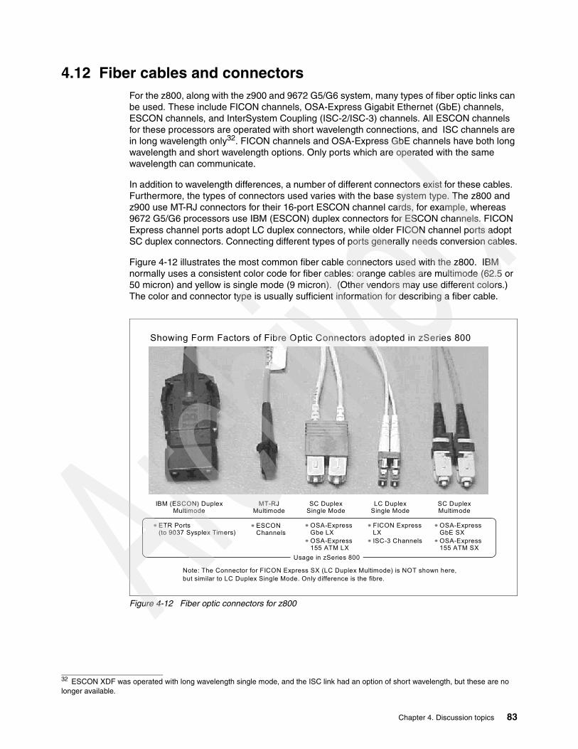
4.12 Fiber cables and connectorsFor the z800, along with the z900 and 9672 G5/G6 system, many types of fiber optic links can be used. These include FICON channels, OSA-Express Gigabit Ethernet (GbE) channels, ESCON channels, and InterSystem Coupling (ISC-2/ISC-3) channels. All ESCON channels for these processors are operated with short wavelength connections, and ISC channels are in long wavelength only32. FICON channels and OSA-Express GbE channels have both long wavelength and short wavelength options. Only ports which are operated with the same wavelength can communicate.
In addition to wavelength differences, a number of different connectors exist for these cables. Furthermore, the types of connectors used varies with the base system type. The z800 and z900 use MT-RJ connectors for their 16-port ESCON channel cards, for example, whereas 9672 G5/G6 processors use IBM (ESCON) duplex connectors for ESCON channels. FICON Express channel ports adopt LC duplex connectors, while older FICON channel ports adopt SC duplex connectors. Connecting different types of ports generally needs conversion cables.
Figure 4-12 illustrates the most common fiber cable connectors used with the z800. IBM normally uses a consistent color code for fiber cables: orange cables are multimode (62.5 or 50 micron) and yellow is single mode (9 micron). (Other vendors may use different colors.) The color and connector type is usually sufficient information for describing a fiber cable.
Figure 4-12 Fiber optic connectors for z800
32 ESCON XDF was operated with long wavelength single mode, and the ISC link had an option of short wavelength, but these are no longer available.
IBM (ESCON) DuplexMultimode
MT-RJMultimode
SC Duplex Single Mode
SC Duplex Multimode
LC Duplex Single Mode
Showing Form Factors of Fibre Optic Connectors adopted in zSeries 800
ETR Ports(to 9037 Sysplex Timers)
ESCONChannels
OSA-Express Gbe LXOSA-Express 155 ATM LX
FICON Express LXISC-3 Channels
OSA-Express GbE SXOSA-Express 155 ATM SX
Note: The Connector for FICON Express SX (LC Duplex Multimode) is NOT shown here,but similar to LC Duplex Single Mode. Only difference is the fibre.
Usage in zSeries 800
Chapter 4. Discussion topics 83
Terminology is also important. The use of SX (short wavelength) and LX (long wavelength) is common. The term Fibre Optic SubAssembly (FOSA) is sometimes used instead of port. An FOSA has a light transmitter and receiver and can convert light signals to electric signals and vice versa. Many installations have fiber patch panels and trunk fiber cables, and these also have ports, although these ports do not have transmitters and receivers.
It is usually not practical to install a new connector on an existing fiber cable. (This type of work requires special tools and training.) IBM can provide conversion cables in order to, in effect, change the connector type of an existing cable. These are 2 m long and have different types of connectors on the two ends.
4.12.1 MCP cablesIBM (through the Fiber Cable Services offering) can provide Mode Conditioning Patch (MCP) cables. These are for use with 1 GB/s links only. They permit channels and devices designed for long-wavelength single-mode operation (using 9 micron cables) to use a previously-installed multimode fibre infrastructure. If you have not yet installed a fiber cable infrastructure, or if you do not plan to reuse multimode fibre cables, we recommend you to use single mode fibres and directly attach them to LX channels and device ports. If MCP cables are used, the distances supported are much more limited, with a general limit of 250 m. MCP cables may be used with:
� ISC-3 CF links to an ISC-2 link on G3 - G6 servers
� OSA-Express Gigabit Ethernet LX cards when connecting with a multimode fiber cable
� OSA-Express 155 ATM LX
� FICON Express LX cards when connecting with a multimode fiber cable
Be aware that MCP cables are required at both ends of the connection (at both FOSAs). MCP cables must be attached directly to FOSAs. Also, you should take care that all the connectors match correctly, because MCP cables for 62.5 micron multimode fiber and 50 micron multimode fiber are different.
4.12.2 Replacement cablesFrom time to time you may need a single cable to replace a damaged one or if an initial order was insufficient. You can order cables from IBM using part numbers. This is not a suitable method for ordering the large number of cables needed for installation, but it is a practical way to order a small number of common cables. The following is a list of the most common cables that might be ordered this way:
Part number Description (MCP and Conversion cables are 2 meters long)21L4172 MCP. OSA Express. 9 micron to 50 micron. SC duplex both ends.21L4173 MCP. OSA Express. 9 to 62.5. SC duplex both ends.21L4175 MCP. FICON LX, GbE LX. 9 to 62.5. SC duplex to ESCON duplex.05N6771 MCP. FICON LX, ISC-3. 9m to 50m. LC duplex to SC duplex.11P4658 MCP. FICON LX. 9 m to 62.5 m. LC duplex to SC duplex.11P4150 MCP. FICON LX. 9m to 62.5m. LC duplex to ESCON duplex05N4808 Conversion FICON LX, ISC-3 9 m. LC duplex to SC duplex.05N4804 Conversion ESCON 16 port 62.5 m. MTRJ to ESCON duplex.11P1373 Conversion FICON SX 50 m. LC duplex to SC duplex.11P1374 Conversion FICON SX 62.5 m. LC duplex to SC duplex.11P2979 Conversion FICON SX 62.5 m. LC duplex to ESCON duplex.11P4417 Conversion FICON SX 62.5 m. LC duplex to MTRJ.11P4418 Conversion FICON SX 62.5 m. SC duplex to LC duplex.11P4419 Conversion FICON LX 9 m. SC duplex to LC duplex
84 Technical Introduction: IBM zSeries 800

The FICON references in this list are all for FICON Express cards, not the older FICON cards.
4.13 Resource LinkResource Link is a Web-based tool that provides you with the information you need to plan for, install, and maintain your IBM zSeries 800 and associated software. This site is an organized collection of information for z800 planning, administration, and education. Registration is required for this site, as well as for several of the tools. This is because it is possible to obtain information about your specific system through Resource Link, and your security is taken seriously by IBM.
After your initial subscription to Resource Link, you may need to apply for access to several of its functions individually. Certain information is accessed either by specific customer number, order number, or machine serial number. This is done to ensure that customers only have access to their own data. We recommend signing up for Machine Information and the CHPID Mapping Tool (under the Tools section) after gaining access to Resource Link since these tools seem to be favorites for customers. In our experience, the library section has also been useful because the complete set of manuals is no longer shipping with zSeries products. Resource Link can be accessed at:
www.ibm.com/servers/resourcelink
Resource Link provides many functions, including:
� Tools that allow you to access machine information and change the default CHPID numbers for the channels on your newly ordered z800
� Planning information and documentation for the installation of your machine
� EC and MCL levels currently applied or missing from your machine with corresponding descriptions
� Access to technical support information
� Status of your HMC and SEs from your last call home
� Web-based multimedia education
� Discussion groups (“forums”) that may be helpful for specific problems33
� Whether or not your machine is on maintenance
4.13.1 Accessing Resource LinkThe first thing you need to do in order to use in Resource Link is to register for the Web site. To register, go to:
www.ibm.com/servers/resourcelink
This will display a sign-in screen. For the first access, you need to click the link marked Register to obtain a user ID and password. The next screen has three sections, one for customers, one for IBM Business Partners, and one for IBM employees. Click the appropriate link. You will then be prompted to enter your e-mail address and your preferred user ID.
33 Other Internet newsgroups, including the IBM news server, are considerably more active than the Resource Link forums and might be considered a better option for general discussions.
Chapter 4. Discussion topics 85

When you click Submit you will receive a message that says Your request is being processed. You will receive an e-mail containing your registration information within six (6) hours. IBM will create a password for you (which you can change later after accessing the site and clicking the User Profiles tab). You are then able to access the Web site.
4.13.2 Resource Link menuOnce you access the site, you can click on any of the announcements on the main page or use the menu at the left to navigate through the site. The menu contains the following tabs: Site Search, User Profiles, Planning, Education, Library, Technical Support, Forums, Feedback, Personal Folders, and Tools. Explore the Web site for a complete list of menu options. This book focuses on the sections which the authors have found most useful to the customer, particularly the Tools section, which is only available on Resource Link.
The Site Search and Feedback menus are typical and do not require explanation. The Library menu contains manuals for your z800 hardware and software, as well as redbooks and technical papers. Personal Folders allows you to organize site content that has been pushed to you via e-mail.
You may want to explore the User Profiles section when you are getting started. The Navigation Profile within this menu allows you to select how you want the Web site information displayed (drill-down or cascaded—we recommend cascaded to save time). You can also change your Resource Link password under Personal User Profile.
The Planning section contains documentation (for example, physical planning) and tools for your S/390 and zSeries products. If you would like a customized physical planning report for your particular order, you can request it by going to User Profiles and clicking Request access to customized planning information. You will need to submit your order number and CCN number, both available from your sales representative. After about an hour, you will receive an e-mail saying that you now have access to that order information.
To look at this information, go to Planning -> zSeries -> Hardware -> z800 -> Customized planning aids. Select your order. You are then able to download a PDF which describes the features and the physical planning information pertinent to your order.
The Education section contains information regarding which courses are available for your system, as well as sections such as “How Do I” and “Tell Me About” where you find answers to frequently asked questions. Sections of manuals are organized and highlighted to answer a specific how to question. This avoids looking through a whole manual if you are looking for a specific task. The majority of this material is directed to HMC and SE tasks. There is also information available on certifications for your product and upcoming conferences and classes.
The Technical Support section provides alerts, known problems, and answers to “How To” questions for both hardware and software. You will find information on additional technical support resources. You can also use the Technical Support Locator and Ask a Technical Question features. Links are provided to IBM support Web sites.
You can subscribe to Group Discussions and ESP Forums. Access to these forums is subscription-based. For example, if you participate in an Early Support Program (ESP), you will be asked to join that particular ESP forum. Forums are generally more useful during the initial availability of a product. Forums allow you to share your experiences and ask questions of IBM and other customers working with the same product. Interest tends to lesson as people become more familiar with the product.
86 Technical Introduction: IBM zSeries 800

There are two valuable Tools available from this site, the CHPID Mapping Tool and Access to Your Machine Information, described in the following sections.
4.13.3 Tools
CHPID Mapping ToolThe CHPID Mapping Tool allows you to change the default CHPID numbers for the channels on a new z800 processor (this tool cannot be used for subsequent upgrades to the machine). Default CHPID numbers are normally assigned by manufacturing. You can use this tool to reassign them by either of two methods:
� Manual - you enter the new CHPID values individually. The CHPID Mapping Tool checks your input for errors.
� Availability Mapping - you supply an IOCP source file, and the CHPID Mapping Tool assigns CHPID values to match your definitions and to provide maximum system availability.
In either case, the CHPID Mapping Tool provides a diskette with the new CHPID values. The IBM Service Representative uses the diskette at system installation to provide the updated CHPIDs.34
You need to register for the CHPID Mapping Tool and receive authorization before you are allowed to use the tool. To register, click the Tools tab of the menu, and click Register the CHPID Mapping Tool. You will need to fill out a registration form with the following fields:
� Customer Number (available from your sales representative)
� Company Name
� IBM Account Representative Name, e-mail, and phone number
Once your registration is received, a note goes to the IBM representative you named asking for confirmation that you are to receive access to the tool. Once confirmation is received, you are sent a note saying that you have access to the tool. In order to use the tool for your new order, you need the CCN number (printed on the CHPID report available from your sales representative). A course describing the tool and how to use it is available at the CHPID Mapping Tool site, as well as CHPID Mapping Tool FAQs.
Machine InformationCustomers have found this reporting information particularly useful for finding information about their installed machines. After clicking the Tools tab on the main menu, you have the option of looking at Machine Information. This allows you to access machine data and system information in the form of reports. You need to register to view your machine information. The form and authorization process are the same as for the CHPID Mapping Tool. You must register by customer number, which allows you to see all of the z800 and z900 machines installed or on order under that customer number. When you access the Machine Information site, you are prompted for your Enterprise Number, Customer Number, or machine serial number. We recommend using a serial number. You have the option of looking at four reports: Customer Data, System Status, EC/MCL, and CHPID.
Customer Data shows customer information such as the system name, enterprise number, customer number, and whether the machine has a maintenance agreement.
34 You can also remap your CHPID addresses after your system is installed. This does not involve the CHPID Mapping Tool described here. See “CHPID mapping” on page 24 for more information.
Chapter 4. Discussion topics 87

System Status shows the power status, the second SE status, and the last ten times the machine called home. You can click the call home listings to find reported system information such as installed storage, a listing of CPs, type and amount of channels, and whether CBU is installed. This has been useful for getting information to customers who do not work directly with the machine, but need up-to-date statistics on it.
EC/MCL lists which MCLs are activated and which have not been applied on the HMC and SE. This report gives you an MCL list complete with descriptions and when they were installed. It also has detailed descriptions of the MCLs that are missing from your system. You can subscribe to EC/MCL data so that you will be notified when a HIPER MCL fix is needed on your particular machine or when MCL updates are recommended.
You need to sign up for each machine individually. To do this, click Subscribe to EC/MCL Data under Shortcuts, and complete the required form. This form asks you whether or not you want to be notified via e-mail or to a folder you have set up previously under the Personal folders tab on the main menu.
CHPID provides a CHPID report with the location, port, description and card serial number of each CHPID.
4.14 Crypto overviewThree different cryptographic hardware elements are available for the z800. All are optional. The three are:
� Cryptographic coprocessor facility (CCF) (feature code 0865). If you order this feature you receive two coprocessors, which are installed on the BPU-PK.. (You cannot order a single coprocessor.) These are slower than the other options for cryptographic processing, but are also used for secure key management by z/OS. For this reason, the coprocessors are a prerequisite for the PCICC and PCICA cards.35 The coprocessors are tamper proof, with a number of techniques designed to prevent extraction of internal keys by physical attacks. The system must be powered down to install these, so Plan Ahead activities can be important.
� PCICC cards (feature code 0861). One of these cards uses one I/O slot and provides two cryptographic processors. Each card occupies two CHPIDs, but there is be no entry in the IOCDS for the cards. The PCICC cards are faster than the coprocessors, with additional functions, but the coprocessors are a prerequisite for them to work. The PCICC cards are also tamper proof. Installation can be concurrent if the required CCF features are already installed.
� PCICA cards (feature code 0862). One of these cards uses one I/O slot and provides two cryptographic processors. Each card uses two CHPIDs, but there is no entry in the IOCDS for the cards. The PCICA cards are optimized for SSL processing and have no other purpose. They are supported by Linux. When used with z/OS, the cryptographic coprocessors are a prerequisite. When used on a Linux-only model, the coprocessors are not required. Installation can be concurrent if the required CCF features are already installed.
35 There is an exception for the Linux-only model where there is no prerequisite for the PCICA area.
88 Technical Introduction: IBM zSeries 800

All three elements are the same as those available on z900 systems and conform to the same rules. The crypto-related feature codes for the z800 are:
Table 4-12 Cryptographic feature codes
Trusted Key Entry (TKE)A TKE is a PC plus an IBM 4758 Cryptographic Adapter card. It is connected via customer LAN to a z800 and communicates with the cryptographic coprocessors and the PCICC cards via ICSF. Using a combination of TKE, ICSF, and z800 cryptographic coprocessor functions, the system administrator can securely control master keys and operational keys from the TKE work station. A number of functions are available, such as requiring keys to be entered in parts (where the different parts are assumed to be controlled by different people). If truly high-security cryptographic controls are important, and are integrated with the “people controls” often associated with these environments, then the TKE functions are important. If this high level of protection is not required, all cryptographic tasks can also be performed via ICSF TSO panels.
Cryptographic Coprocessor Facility (CCF)The Cryptographic Coprocessors, as well as the 4758-2 used within the PCICC Card, have earned Federal Information Processing Standard (FIPS) 140-1 level 4, the highest certification for commercial security ever awarded by the U.S. Government.
The cryptographic coprocessor facility (CCF) contains sixteen sets of internal key and working registers, allowing it to be used with multiple LPARs with each LPAR having a different set of master keys. That is, each LPAR appears to see a dedicated set of cryptographic coprocessors. These are known as cryptographic domains and map exactly to LPARs. Each set of master keys consists of the DES master key, the PKA KMMK (key management master key) and the PKA SMK (signature master key).
The CCFs offer cryptographic services such as DES, Triple DES, CDMF, MAC'ing, PIN Processing, SHA-1, hardware pseudo random number generator, and Key Management concurrent with asynchronous cryptographic functions such as 1024-bit RSA, and Digital Signature Standard with secure remote master key entry. The cryptographic coprocessors cannot be used to generate RSA keys. Each coprocessor is a single specialized processor, controlled by the z/OS Integrated Cryptographic Services Facility (ICSF).
Feature Code Description
0800 Cryptographic support enabled (includes the two cryptographic coprocessors, batteries and necessary cables)
0861 PCI Crypto Coprocessor Card PCICC (maximum of 8)
0862 PCI Crypto Accelerator card PCICA (maximum of 6)
0865 T-DES with PKA for PCICCa
a. The security level for the PCICC must match the security level of the CCFs.
0875 T-DES with PKA and TKEb according to the Security Level; applicablec
b. FC0875 will be used to support all TDES orders, regardless of wether or not the orderrequires a TKE.c. See “Security Levels” in this chapter.
0876 TKE PC with Ethernet connection
0879 TKE Token Ring adapter
Chapter 4. Discussion topics 89

To prevent the loss of master keys during power outages, a cryptographic battery unit is provided with the CCFs, and is mounted inside the system frame. The battery has a shelf life of 10 years. It is switched off during shipment to avoid unnecessary drain. There are an estimated 3000 hours of current drain associated with this battery.
Security levelsThere are five security levels for the enablement of the cryptographic coprocessors:
� Triple/DES with PKA for USA/Canada only, it provides the highest level of security offered.
� Triple/DES with exportable PKA for companies in other countries where an export license has been granted.
� DES with PKA for USA/Canada only.
� DES with exportable PKA for other countries except export-restricted countries.
� CDMF (Commercial Data Masking Facility) provides the lowest level of security and is available to everyone else except for those countries which the U.S. Government has identified as being ineligible for any level of security.36
The cryptographic coprocessors are enabled by IBM Service personnel during installation or when required with a unique enablement diskette, which will run only on the coprocessor it was created for. A Power-on-reset is required to complete this task.
4.14.1 PCICC cardsUp to eight PCICC cards may be ordered; however, the total number of PCICC and PCICA cards cannot exceed eight. A card is feature code 0861. Each card contains two cryptographic processors. It also contains 16 key and working registers, which can support multiple LPARs. The PCICC cards also hold up to 16 sets of DES master keys and PKA master keys. The PKA master keys have to be of the same values as the PKA signature master keys entered in the CCFs.
In addition to the CCF cryptographic capabilities, the PCICC cards offer RSA Key generation for public/private key pair generation, 2048-bit RSA signature generation and Retained Key support (RSA private keys generated and kept stored within the secure hardware boundary). The PCICC cards are managed by the z/OS Integrated Cryptographic Services Facility (ICSF), which provides cryptographic service requests automatically balanced among all available suitable cryptographic engines. The security level for the PCICC must match the security level of the CCFs. PCICC cards cannot be ordered with the Linux-only z800 model.
Attention: When a Service Action requires the removal of the BPU-PK, containing the MCM, memory and the cryptographic coprocessors, the Battery has to be disconnected. All stored customer keys will be lost. It is the customer’s responsibility upon completion of the maintenance task to restore the keys.
36 The TKE can only be ordered with any of the DES or Triple-DES features, but not with CDMF.
Important: The cryptographic enablement diskette is the property of the customer. The customer should exercise due care in the protection and storage of this diskette. It is the customer’s responsibility to zeroize keys and clear loaded configuration data in the event the processor is resold, relocated, or subject to some other change that affects or could affect the export agreement. The cryptographic enablement diskette should not be included in the reselling or relocation of the processor unless granted approval by the export offices involved.
90 Technical Introduction: IBM zSeries 800

There are several status LEDs on the PCICC card, which have the following meaning:
Table 4-13 PCICC LED A0/A1 and B0/B1 indicatiors
Table 4-14 PCICC LED-C0/C1 indicator
In a manner similar to the cryptographic coprocessors, the PCICC cards are enabled via a unique FCV Diskette (Functional Control Vector). This procedure to activate the PCICC cards does not require a Power-on-reset.
If a defective card must be returned to IBM, there is an additional level of protection offered to the customer. The intrusion latch is set after card removal. However, the customer keys remain in card memory. If the customer requests the keys be erased, battery power must be removed from the card. There is an access window on the card to allow the IBM Service Representative to cut the battery lead wire. Cutting this wire removes power so that all stored data is lost immediately and the card is useless.
User Defined Extension (UDX) facilityThe PCICC cards support the secure loading into the PCICC firmware of user-customized extensions to the cryptographic functions provided. The User Defined Extension (UDX) facility can be used to add custom functions to the standard Common Cryptographic Architecture (CCA) command set. Custom functions are executed inside the secure module of the 4758-based card with the same security as the other CCA functions.
Test completeLED A (green)
Not Operational LED B (amber)
Card Status
off off No power or card processor in a loop
off flashing Diagnostics running
off on Normal after card exchange from Power On until Diagnostics start
flashing off Diagnostics complete, CHPID online
flashing on Hardware error detected
on off Normal after card exchange and diagnostics completed until customer activates card
LED C (green) Card Status
Off ONLINE, communicating
On OFFLINE for maintenance or an external wrap test is running
Rapid flashing POWER ON test running
Attention: There is an intrusion latch within the PCICC card which is set any time the card is removed from the system. If the card is reinstalled and the customer attempts to activate the card using ICSF, ICSF will detect the intrusion latch and zeroize the customer keys, which prevents activation. The customer must reenter the keys to make the card available for use.
Chapter 4. Discussion topics 91
4.14.2 PCICA cardsUp to six PCICA cards may be ordered. However, the total number of PCICC and PCICA cards cannot exceed eight. Current experience indicates that maximum throughput is reached with two cards. A card is feature code 0862. Each card contains two cryptographic processors. That is, other processing considerations are such that only two PCICA cards are needed to reach the maximum throughput of the z800 system.
The PCICA card is designed specifically for SSL (Secure Sockets Layer) processing, handling any key size up to 2048 bits. It does not support symmetric cryptography, cannot manage keys, and is not tamper proof. Each processor (there are two per card) can support up to 2100 SSL handshakes per second. Note that the system cryptographic coprocessors and the PCICC cards can also handle SSL handshakes, but not at the same rate.
Multiple LPARs can be supported. This is managed by the z/OS Integrated Cryptographic Services Facility (ICSF), in an attempt to balance the cryptographic workload between the installed components.
Starting with z/OS V1R2, ICSF and system SSL functions will automatically use PCICA processors, if available. Usage includes:
� z/OS HTTP server, WebSphere, TN3270 server, LDAP server, and the CICS Transaction Gateway server,
� Applications that call ICSF directly for clear key RSA operations.
Linux for zSeries will also support the PCICA card for SSL usage. This applies whether the Linux-only model is used, or an IFL on a general purpose model, or if Linux is running under a normal CP, or if Linux is under VM. See “Linux” on page 40 for a discussion of Linux releases.
4.14.3 Practical mixFor the Linux-only models 0LF of the z800 there are only PCICA cards orderable.
The general purpose models require the presence of the CCFs, even if the machine is just intended to use the SSL capabilities via the PCICA cards under Linux.
The general purpose models, in order to use cryptographic services for Web serving, would typically have the two CCFs and a maximum of two PCICA cards.37 The number of PCICC cards needed depends heavily on the nature of the cryptographic workload other than SSL handshakes. The ability of ICSF to automatically balance cryptographic workloads among the various cryptographic hardware elements available is an increasingly important function of z/OS.
4.14.4 RMF for cryptoRMF (Resource Measurement Facility, a program product for z/OS) can provide detailed reports about the utilization levels of PCICC and PCICA cards. This reporting is available in PTF UW99368 for z/OS V1R2.
37 In general, a z800 will not need more than two PCICA cards. Two cards provide sufficient SSL handshaking capacity to drive the remaining capacity of the z800.
92 Technical Introduction: IBM zSeries 800

For PCICC cards, RMF reports on the request rate (requests per second), the execution time (average duration to service each request, in microseconds), and the percentage utilization of each card. For PCICA cards, RMF reports the same information plus additional statistics for several RSA operations. For the cryptographic coprocessors, RMF reports on single and triple DES encryption, MAC generation and verification, HASH, and PIN verification and translation functions.
This RMF support is quite important. It provides a way to verify that the cryptographic hardware is being used as expected and to determine when additional cryptographic engines are needed.
4.14.5 Cryptographic performance planning for SSLEarly use within IBM produced the following maximum performance for SSL handshakes:
� 93 per second for a single CCF engine� 186 per second for both CCF engines� 130 per second for a single engine on a PCICC card� 260 per second for both engines on a PCICC card� 1070 per second for a single engine on a PCICA card� 2140 per second for both engines on a PCICA card
As can be seen, these functions scale perfectly at the indicated performance levels. The usual cautions and disclaimers about performance numbers apply here. Your results may differ. It is probably safe to say that your results will differ in a real-world Web environment because there are so many dynamic factors affecting Web processing. Also, note that an SSL handshake is only part of the SSL protocol. Once the handshake completes, symmetric cryptography (usually DES) is used for all the protected data. When large amounts of data are involved this processing becomes significant, and can be handled by the CCF or PCICC processors. The Linux-only models 0LF of the z800 do not support the CCFs or the PCICC cards, so the asymmetric part of the SSL protocol is performed via the PCICA cards; the rest of the data encryption has to be performed by the software.
The numbers given here represent a sustained rate, but are for a system without significant application workload. A practical system will need to devote time to applications as well as SSL handshakes. Not all of the SSL and DES processing is done by the cryptographic engines, and heavy application workloads can lower these numbers.
4.15 Sysplex Timer connection The IBM 9037 Sysplex Timer provides the synchronization for the Time-of-Day (TOD) clocks of multiple CECs, and thereby allows events started by different CECs to be properly sequenced in time. When multiple CECs update the same database and database reconstruction is necessary, all updates are required to be time-stamped in proper sequence.
In a sysplex environment, the allowable differences between TOD clocks in different CECs are limited by the inter-CEC signalling time, which is very small (and is expected to become even smaller in the future). Some environments require that TOD clocks be accurately set to an international time standard. The Sysplex Timer and the Sysplex Timer attachment feature enable these requirements to be met by providing an accurate clock-setting process, a common clock-stepping signal, and an optional capability for attaching to an external time source.
Chapter 4. Discussion topics 93

The IBM 9037-2 can have a minimum of four ports and a maximum of 24 ports. Ports can be added with a granularity of four ports per additional 9037-2 port card. 9037-2 port cards are hot-pluggable, which means that they can be plugged in without requiring the 9037-2 unit power to be turned off. 9037-2 port cards can therefore be concurrently maintained, added or removed.
The z800 connection to a Sysplex Timer is necessary if the z800 is to participate in a basic or parallel sysplex environment. The connection to the timer is mandatory; this connection guarantees that all systems in a sysplex environment will have the same clock time.38
The z800 has two fiber optic ports, each of which is attached to a Sysplex Timer using a fiber optic cable. In an expanded availability configuration, each fiber optic port should be attached to a different Sysplex Timer in the same ETR network. This ensures that redundant Sysplex Timer paths are made available to all attached CECs.
The Sysplex Timer is not channel-attached and, therefore, is not defined to the Input/Output Configuration Program (IOCP), MVS Configuration Program (MVSCP), or Hardware Configuration Definition (HCD).
Each connection from a 9037 port to the z800 attachment port requires two individual fibers, one that carries signals from the 9037 to the CPC and another that carries signals from the z800 back to the 9037. A fiber optic cabling environment could use ESCON jumper cables, trunk cables, distribution panels, and various connector types. Either 62.5/125-micrometer or 50/125-micrometer multimode fiber can be used.
The cable connector used to connect an external IBM 9037 Sysplex timer to the z800 differs from the cable used for a z900. The z900 connector is an MT-RJ connector, the same as used for the “new” ESCON channels. The z800 connector is the same as the one used on the “old” ESCON cables (and still used on the control unit end of ESCON cables), and is shown in Figure 4-12 on page 83.
4.16 Optica planningOptica Technologies, Incorporated, is a company based in Ohio that designs and manufactures a range of connectivity products. More information can be found at www.OpticaTech.com. The product we discuss here is the 34600 FXBT ESCON Converter, which we refer to as the converter. It converts an ESCON channel to a parallel channel. Optica produced two earlier converters, including one quite similar to IBM’s Pacer unit. The converter described here is new and has been designed for z800 systems. It has been tested with early z800 machines.
IBM recommends these converters for connecting older parallel channel control units to z800 ESCON channels. Optica is not part of IBM. It is a separate company and you must order the converters directly from Optica.39 IBM is not involved in the ordering process. You should place orders in a timely manner so that the converters are available when your z800 is delivered.
38 An external Sysplex Timer is not required if the Parallel Sysplex environment exists completely within a single z800 or z900.39 IBM may remarket the Optica converter in some countries, and these statements must be modified accordingly.
94 Technical Introduction: IBM zSeries 800

The converter is a small box, about 7.5” wide, 2” high, and 12” deep (19 cm x 5 cm x 30 cm) and connects to a utility power outlet (100v - 240 v, 50/60 Hz). The front panel is shown in the sketch in Figure 4-13 on page 95. Each converter handles one ESCON channel and one parallel control unit connection.40 The converters may be individually positioned (most common) or rack mounted (not so common). Rack mounting consists of a cage than fits a standard 19 inch rack and holds 8 converters. Each unit requires its own power connection in the rack.41
Figure 4-13 Converter front panel
The most common location for the converters is under a raised floor. They are rugged units that do not need to be monitored. Each converter has an internal fan, but the unit can function indefinitely without the fan if there is a reasonable cool air flow--as there usually is under a raised floor. A typical z800 installation might have several converters placed under the raised floor, in convenient locations to connect to existing bus and tag cables. New ESCON cables would be run from the converters to the z800. The only other requirement would be for utility power outlets under the floor, to run the converters.
Figure 4-14 illustrates the conceptual design of the converter. The FIFO elements are “bit buffers” and the channel interfaces include the appropriate transmitters and receivers. Internal control is by an IBM PowerPC microprocessor core. This is used to program the gate array. Normal channel data movement is completely handled in the gate array, permitting full- speed channel operation (200 Mbit/sec ESCON and 4.5 MBytes/sec parallel). The microprocessor interprets channel commands and provides the logic for status conversion and so forth.
40 Control units may be daisy chained, as usual, with the same restrictions that exist when using “real” parallel channels.41 The same unit is used for individual positioning or rack mounting. Rack mounting causes two small tabs to be added to the converter case; these secure the converter to the cage in the rack.
Power NotOper
FiberActive
Error CUActive
(Fan) OpticaTechnologies Incorporated
Chapter 4. Discussion topics 95
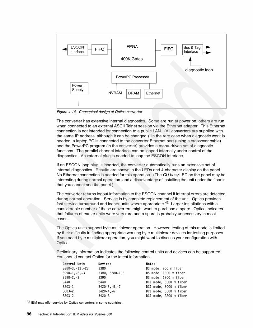
Figure 4-14 Conceptual design of Optica converter
The converter has extensive internal diagnostics. Some are run at power on, others are run when connected to an external ASCII Telnet session via the Ethernet adapter. This Ethernet connection is not intended for connection to a public LAN. (All converters are supplied with the same IP address, although it can be changed.) In the rare case when diagnostic work is needed, a laptop PC is connected to the converter Ethernet port (using a crossover cable) and the PowerPC program (in the converter) provides a menu-driven set of diagnostic functions. The parallel channel interface can be looped internally under control of the diagnostics. An external plug is needed to loop the ESCON interface.
If an ESCON loop plug is inserted, the converter automatically runs an extensive set of internal diagnostics. Results are shown in the LEDs and 4-character display on the panel. No Ethernet connection is needed for this operation. (The CU busy LED on the panel may be interesting during normal operation, and a disadvantage of installing the unit under the floor is that you cannot see the panel.)
The converter returns logout information to the ESCON channel if internal errors are detected during normal operation. Service is by complete replacement of the unit. Optica provides fast service turnaround and loaner units where appropriate.42 Larger installations with a considerable number of these converters might want to purchase a spare. Optica indicates that failures of earlier units were very rare and a spare is probably unnecessary in most cases.
The Optica units support byte multiplexor operation. However, testing of this mode is limited by their difficulty in finding appropriate working byte multiplexor devices for testing purposes. If you need byte multiplexor operation, you might want to discuss your configuration with Optica.
Preliminary information indicates the following control units and devices can be supported. You should contact Optica for the latest information.
Control Unit Devices Notes3880-3,-13,-23 3380 DS mode, 900 m fiber3990-1,-2,-3 3380, 3380-CJ2 DS mode, 1200 m fiber3990-2,-3 3390 DS mode, 1200 m fiber2440 2440 DCI mode, 3000 m fiber3803-1 3420-3,-5,-7 DCI mode, 3000 m fiber3803-2 3420-4,-6 DCI mode, 3000 m fiber3803-2 3420-8 DCI mode, 2800 m fiber
42 IBM may offer service for Optica converters in some countries.
FPGA
400K Gates
FIFO FIFOESCONInterface
Bus & TagInterface
PowerPC Processor
NVRAM DRAM Ethernet
PowerSupply
diagnostic loop
96 Technical Introduction: IBM zSeries 800

3480 3480, 3490 HST,DS modes, 3000 m fiber3174-x1L (many) DCI, HST, DS modes, 3000 m fiber3274 (A,B,D) (many) DCI mode, 3000 m fiber5088 (5081, etc) HST, DS modes, 3000 m fiber6098 (various) HST, DS modes, 3000 m fiber3172 (LAN, TP) DCI, DS modes, 3000 m fiver3720, 3725 (TP, LAN) DCI mode, 3000 m fiber3745 (TP, LAN) DCI, DS modes, 3000 m fiber8283 DCI, DS modes, 3000 m fiber(3262-5, 3800-1, 3820-1, 4245, 4248,6262) DCI mode, 3000 m fiber(3800-3,-6,-8, 3825, 3827, 3835) HST, DS modes, 3000 m fiber3088 CTC HST, DS modes, 3000 m fiber9032, 0933 see Optica specification sheet38143848 crypto DCI, DS modes, 3000 m fiber3890-XP DCI mode, 3000 m fiber3897/3898 DCI, DS modes, 3000 m fiber4753 DCI, DS modes, 3000 m fiber
In this list, the mode notation is:
DCI = Direct Current Interlock (single tag mode)HST = High-Speed Transfer (DCI alternate tag mode)DS = Data streaming
The maximum ESCON fiber distances mentioned (usually 3000 m) must be reduced by 200 m for every ESCON Director in the path. Other limitations exist for specific devices; you should verify your intended use with Optica.
A converter can be placed on the output side of an ESCON director, between the director and a control unit. Optica documentation shows this configuration only for IBM 9032-005 directors; for any other model we suggest you contact Optica for more information. When an ESCON Director is used in the path, it must be configured as a dedicated connection.
Each converter includes a cable for bus and tag connections. This cable has a single large D shell on one end and splits into two cables with standard parallel channel connectors. No ESCON cables are included.
Optica Technologies Incorporated can be reached at:
700 Pleasant Valley Drive
PO Box 848
Springboro, Ohio 45066-0848
Telephone: (937) 704-0100
Fax: (937) 704-0101
4.17 Upgrade to 2064A four-way z800 (2066-004) can be upgraded to a four-way z900 (2064-104). The z900 can then be upgraded to other z900 models. You retain the I/O cards and serial number from the z800, but the rest of the machine is swapped for a z900 machine.
Chapter 4. Discussion topics 97

4.18 Support Element and Hardware Management ConsolesThe purpose and use of the Support Elements (SEs) and Hardware Management Consoles (HMCs) is familiar to experienced S/390 customers. They are probably unfamiliar to customers who have not worked with S/390s before and have no direct analogs on other platforms. For this reason we include brief introductory information, as well as configuration information for the z800. Table 4-15 on page 99 and Table 4-16 on page 100 provide the feature codes associated with z800 SEs and HMCs.
4.18.1 Support ElementA Support Element is an IBM ThinkPad mounted inside the z800 frame. Two SEs are standard with a z800 system. The first, or primary, Support Element is used for monitoring and control of the system. The second Support Element, referred to as the alternate SE, provides redundancy in case the first one fails. The two SEs are connected to the Central Processor Complex (CPC) via the Power Service and Control Network 2000 (PSCN-2000), which consists of two redundant 100 Mbit/s Ethernet networks for cage connection; this is briefly described in 2.3, “System control” on page 19. Standard TCP/IP protocols are used on these interfaces.
A support element is critical for system startup and operation, and includes these functions:
� IOCDS files are stored in the SEs. An IOCDS is selected and loaded during a system Power-on-reset (POR) operation.
� It provides the communication link to one or more HMCs.
� It provides many operator and maintenance interface screens. These functions are typically used from an HMC (which communicates with the SE), but can also be used directly from the SE.
� It monitors the Central Processor Complex.
Automatic mirroring copies critical configuration data and log files from the primary SE to the alternate SE twice a day. Mirroring can also be performed manually. The alternate SE has a special workplace with limited tasks available. It is only used by IBM service personnel. If the primary SE fails, an automatic switch-over is performed and the former alternate SE becomes the primary support element.
Alternate Support Element Preload (see Figure 4-15) allows service personnel to preload a new CPC internal code level on the alternate support element while the remainder of the system is running. Then, at a time convenient to the customer, a disruptive switch is made to the support element with the new internal code and the support element with the old code level is brought to the new level using a hard disk restore. The CPC is then activated with the new code level. Alternate Support Element Preload shortens the outage required for the update from 3 hours on previous systems to approximately 20 minutes.
98 Technical Introduction: IBM zSeries 800

Figure 4-15 Alternate Support Element Preload
Table 4-15 SE feature codes
4.18.2 Hardware Management ConsoleA Hardware Management Console (HMC) is a remote PC, connected by a LAN to both Support Elements. An SE is inside a system frame; an HMC is typically located with the system operators. An SE is associated with a single system; an HMC may be connected to multiple systems. An SE and HMC run essentially the same application program, which is provided by IBM (both run under OS/2). This application program provides screen interfaces to start the z800 system, stop it, configure it, maintain it, and so forth. The same functions can be performed at an SE or an HMC, but the HMC is usually in a more convenient location and can be used with multiple systems.
The HMC can operate an internal Web server, that extends the entire HMC desktop to a remote PC via a browser interface. This function has performance limitations; it is useful for unusual situations but would probably not be used for routine operations. Though the Web function provides either a secure or a secure and a non-secure connection, it has obvious
Feature Code Description Comment
0086 Two SEs with token ring and Ethernet adapter
0087 Two SEs with two Ethernet adapters
0088 MAU required for token ring connection Automatically added by configurator if SE has token ring and Ethernet adapter
0089 HUB required for Ethernet connection Automatically added by configurator if SE has only Ethernet adapter
Chapter 4. Discussion topics 99

security exposures if used on a public LAN.43 Both connection types require user IDs and passwords to establish the connection. In addition to the Web server activation, the user IDs must have Web access enabled in their corresponding user profiles.There are two interfaces you can choose from:
� Perform Hardware Management Console Application tasks
This selection lets you log on to the Hardware Management Console Web server for monitoring CPCs and CPC images with a limited subset of task lists and tasks available from the Hardware Management Console.
� Remote entire Hardware Management Console Desktop
This selection lets you log on to the Hardware Management Console Web server and have access to the Hardware Management Console application, as well as all other applications on the desktop. Only one browser can control the entire desktop at a time.
Table 4-16 HMC feature codes
4.18.3 SE and HMC connectivityConfiguring and ordering SEs and HMCs requires understanding the LAN interfaces involved. Both units normally have two LAN interfaces. The general rules are these:
� An SE is connected to a given HMC by only one LAN.
� In simple situations the second LAN interfaces included with SEs and HMCs are not used.
� The two LAN interfaces on an SE may be used to connect to different sets of HMCs, using two independent LANs.
� The two SE LAN interfaces may be both Ethernet, or one token ring and one Ethernet. An option of two token ring interfaces is not available.44 Both SEs in a system will have the same LAN configuration.
� A default HMC configuration always has one Ethernet and one token ring interface.
43 Secure connection just means SSL-encrypted data transfer.
Feature Code Description Comment
0023 Token Ring Adapter for FC 0073 HMC
0024 Ethernet Adapter for FC 0073 HMC
0047 DVD Ram For FC 0073 HMC
0073 HMC, white covers Current HMC
0074 HMC with DVD, token ring and Ethernet adapter, New model, business black covers
6090 17” white consolea
a. The selection of a white or black console is based on availability at the time of manufactureand, at the time of writing, is not a customer choice.
For FC 0073 HMC
6091 21” white console For FC 0073 HMC
6092 17” business black console For FC 0074 HMC
6093 21” business black console For FC 0074 HMC
2904 Modem 120 volts Country dependent
2941 Modem 220 volts Country dependent
100 Technical Introduction: IBM zSeries 800

SEs and HMCs may be connected via public LANs, but this is typically not done for several reasons:
� It is an obvious security exposure.
� It could result in connection losses, which would probably impact customer operation.
� MCL distribution from HMC to SE cannot tolerate connection losses.
� An SE upgrade or restore is quite sensitive, and could be impacted if there is much traffic the used LAN.
A very common arrangement is to use at least two HMCs, one near the system and the other at systems operation on a dedicated LAN.
You may use an existing HMC (and not purchase a new one) to control your z800 system. It must be a feature code 0073 or 0074 HMC with the same (or higher) driver level as the SE. The following discussion assumes that you purchase a new HMC with your z800. You can purchase any reasonable number of HMCs to use with the system.45 You have the following choices when you order your system:
� SEs with a token ring and an Ethernet adapter (feature code 0086)
These are supplied with two 23 m (75 ft.) token ring cables and two 3 m Ethernet cables.
� SEs with two Ethernet adapters (feature code 0087).
These are supplied with four 15 m and four 3 m Ethernet cables.
� HMC with one token ring and one Ethernet adapter (feature code 0074)
You must select this feature, unless you plan to use an existing HMC. You can order several of these features (HMCs) if you need them.
The HMC comes with a 23 m (75 ft.) token ring cable. You must supply any Ethernet cables needed.
� A display for the HMC (feature code 6092 for a 17-inch display, or feature code 6093 for a 21-inch display)
The larger display is nice but it is considerably larger and heavier.
� An MAU (which is like a hub for token ring LANs, feature code 0088)
This is automatically ordered by the IBM system configurator program if the SEs have a token ring interface. The MAU can be deleted from the order if you already have one. Only one MAU will be automatically included in the configuration.
� An Ethernet hub (feature code 0089)
This is automatically ordered by the configurator program if you ordered your SEs without token ring adapters. You can delete it from the order if you already have a suitable hub. Only one hub will be automatically included in the configuration.
The SE and HMC Ethernet ports can run at 10 Mbps or 100 Mbps and autosense the LAN speed. The Ethernet hub may run at 10 or 10/100 Mbps, depending on the exact model used.
44 There is no obscure theoretical reason for the mixture of LAN interface types offered. It is based on the practical observation that an Ethernet port is now included on the planar board of most PCs, whether you use it not.45 Up to 32 HMCs can be used to control your z800 system.
Chapter 4. Discussion topics 101

Figure 4-16 Basic SE - HMC connections
Figure 4-16 illustrates a basic SE/HMC configuration. This example uses Ethernet. The mixed token ring/Ethernet SEs would work just as well. A second HMC might be connected to permit operator actions from a different location.
What is not shown in this illustration is important. The second Ethernet interfaces are not connected to the LAN. OS/2 (the operating system for SEs and HMCs), in the implementation used for these functions, will not automatically use a second interface to the same LAN as an alternate path if the first interface fails.
The modem shown in the sketches is required if a LAN connection from the HMC to the IBM Network is not available.46 The modem is feature code 2904 for 120 volts or feature code 2941 for 220 volts. It is used for Remote Support Facility (RSF) connections to transfer MCLs and system status information via automated scheduled transmissions. If an error occurs, the HMC places a call to the IBM Support System, alerting IBM and transferring error information and logs to reduce the impact of unplanned outages.
Figure 4-17 illustrates use of both LAN adapters in the SEs. This illustration uses Ethernet, but the principles are the same if token ring is used for one of the LANs.
Figure 4-17 Alternate LAN use
46 This option is not available in secure accounts, where a connection to the IBM Support System via modem is not allowed. A LAN connection to a public Internet Service Provider is sufficient for connection to IBM facilities.
z800
SE1EnEn
HMC
EnTR
SE2EnEn
LAN
HMC
EnTR
modem
z800
SE1EnEn
HMC
EnTR
SE2EnEn
LAN 1
HMC
EnTR
LAN 2
102 Technical Introduction: IBM zSeries 800

In the examples in both figures, other z800 or z900 systems might be connected to the same LANs to share the HMCs.
4.18.4 HMC levelsAn existing HMC can be used to control a z800 if the HMC is at an appropriate level. These levels are designated by feature code numbers. Use with a z800 requires an HMC to be at FC0073 or FC0074 level. An HMC associated with a z900 or an earlier system might be upgraded to one of these levels. The characteristics of the two levels include:
� FC0073 level (supplied with initial z800 deliveries):
– 128 MB storage and a DVD drive (FC0047).– Pentium III running at 866 Mhz; 133 Mhz bus; Intel 815 video chip.– No on-board Ethernet is provided. An adapter must be ordered if Ethernet is used.– Three slots are available for communication adapters:
• Token ring adapter (FC0023) is normally in PC slot 3.• Ethernet adapter (FC0024) is normally in slot 2.• WAC adapter (FC0038) can be in slot 4.• 3270 adapter (FC0036) can be in slot 4.
The WAC and 3270 adapters cannot be ordered with new units, but may be present on HMCs purchased for earlier systems. They are no longer used by the HMC function.
� FC0074 (newer level, anticipated for later z800 deliveries):
– 512 MB ECC memory and a DVD drive.– 40 GB disk drive.– Pentium 4 processor running at 1.4 Ghz.– Ethernet on the planar board.– The WAC and 3270 adapters cannot be used.– PCI token ring adapter.
The same HMC functions can be performed with either version, although WAC (SDLC) and 3270 coax inks are not available with the FC0074 version. Recently produced FC0073 units no longer include the WAC and 3270 adapter cards. The progression from the FC0073 level to the FC0074 level is driven primarily by changing PC technology. In practical terms, this means that the base PC used for the FC0073 level is being phased out by the IBM PC company. There appears to be no functional difference to the z800 user between these two HMC levels.
4.18.5 Practical management of SE and HMCHMCs as well as the SEs can be rebooted almost any time without impacting system operations. The HMC could even be turned off, but since the HMC provides the connection to the IBM support system and performs scheduled transmissions and also error reporting if necessary, we do not recommend it.
The HMC is supplied with the IBM Antivirus program. The program is set up to check for viruses every night at midnight. If a problem is detected, a service call is automatically placed for notification to IBM Service. Users should not modify the anti-virus program in any way. Any updates to the program will be made in the same way as the rest of the HMC: via MCLs or EC upgrades.
Chapter 4. Discussion topics 103

4.19 Remote model upgrades: CUoD and CBUThere are two upgrade options that can function remotely; that is, without an onsite change by IBM or an IBM business partner. These are:
� Capacity Upgrade on Demand (CUoD)� Capacity Backup (CBU)
Both of these depend on the availability of spare PUs in the system. If you are using all available PUs, then you cannot use any of these upgrade functions.47 You might also review the considerations described in 4.23, “Spare PUs” on page 114.
The various upgrades can be a little confusing; we briefly describe them here. For example, the term call home is used. If the z800 HMC has a connection to the IBM network, then this connection is used to call home. Otherwise, the modem connected to the HMC will be used.48
4.19.1 Capacity upgrade on demand (CUoD)This provides the capability to add one or more Central Processors (CPs), Internal Coupling Facilities (ICFs), Integrated Facility for Linux (IFLs), or any of the available I/O cards. The upgrade is nondisruptive if the original machine is a model 001, 002, or 003, and the target model (after upgrade) is one of these models or a model 004. Stated a different way, the upgrade is nondisruptive if it does not involve models 0A1, 0B1, 0C1, or 0A2. A nondisruptive upgrade means that it is not necessary to re-IPL z/OS. A disruptive CUoD upgrade simply means that an IPL is required if the upgrade changes any processors used by z/OS. CUoD is a standard function so there are no feature codes needed or RPQs. You order it as you would a regular upgrade.
CUoD for processor additions is straightforward. The first thing to consider is the designation of reserved CPs for the LPAR that will receive the added CP resource after the CUoD is performed. CPs are reserved when you create the image profile of the LPAR. For example, if you had a model 002, but knew you would eventually upgrade to a model 004, you would define 2 CPs to be reserved when you created your LPAR image profile. See 4.9, “LPAR setup and examples” on page 74.
Once the additional CP has been added, you could issue a display CPU command to see which CPs are shown as offline. You could then configure that CP online. Once that is done, the additional engine will now be online, with no need to IPL again. If you did not designate CPs as reserved when you initially configured the LPAR, then you will need to deactivate the partition, add reserved CPs, and then reactivate the partition, which will be disruptive to that LPAR.
4.19.2 Capacity backup (CBU)This function is intended for use as part of a disaster recovery plan. It provides a temporary activation of one or more PUs (assuming they are available). The assumption is that a disaster in another part of the enterprise makes it necessary to temporarily move workload to the z800. The CBU function then enables one or more spare PUs to accommodate the increased workload. The capacity increase is non-disruptive (on models 001, 002, and 003);49 that is, it does not require an IPL or POR operation. CBU is not available on model 004 systems because there are no spare PUs available on this model.
47 Remember that a PU can be used as a normal S/390 processor (CP), or as an IFL engine, or as a CF engine.48 This option is not available in secure accounts, where a connection to the IBM Support System via modem is not allowed.49 An IPL may be required for z800 models 0A1, 0B1, 0C1, and 0A2.
104 Technical Introduction: IBM zSeries 800

Table 4-17 illustrates the CBU upgrades available. The term nondisruptive means the CBU upgrade can take place without re-IPLing z/OS. Disruptive means that z/OS must be re-IPLed after the upgrade. The entry n/a means the indicated upgrade path is not available or does not apply. CBU upgrades to models 0B1, 0C1, and 0A2 are not available.
Table 4-17 Available CBU upgrades
A basic assumption is involved for CBU: It assumes that the normal z800 installation (before using the CBU function) has sufficient memory, I/O resources, and LAN/WAN connectivity to handle the additional CBU workload. That is, the CBU function provides only additional processor power. There is also an assumption that CBU is used for true disaster recovery and not for routine processing peaks. There is a provision to test CBU for up to 10 days, but there are no provisions to use it frequently. In a real emergency, it may be used for up to 90 days.
In order to use CBU, an enabling feature is needed. This is feature code 3704. IBM Service personnel will receive a CBU enabling diskette and install it concurrent to customer work. Then the machine is CBU ready. All CBU-related tasks have to be performed at the SE or at the HMC via Single Object Operations.
To allow CBU to be activated (via an RSF Call to the IBM Service Support System), log onto the SE as user SYSPROG, select Console Actions, then Enable Console Services, and then check the Option CBU enable.50
Another option for enabling CBU is via a password panel. When you initiate CBU, the machine displays PU Serial Number and PU Detailed Data. Write down this data and communicate it (together with your customer number, name, and phone number) to IBM and request a CBU password. You will be contacted within an agreed time with the CBU password, which you then enter at the same panel that displayed the CBU data. This option does not require a call home from the z800.
After three unsuccessful attempts to enter the password, the CBU feature will no longer be available to the system. Contact IBM for a new CBU record and its password.
Testing or activating CBUYou can use CBU in the two following ways:
� You may initiate up to five CBU test sessions by selecting either Test Capacity Backup (CBU) using Password Panel or Test Capacity Backup (CBU) using IBM Service Support System51 under CPC Configuration at the Perform Model Conversion icon. Each
To model 002 To model 003 To model 004
From model 0A1 disruptive disruptive disruptive
From model 0B1 disruptive disruptive disruptive
From model 0C1 disruptive disruptive disruptive
From model 001 nondisruptive nondisruptive nondisruptive
From model 0A2 n/a disruptive disruptive
From model 002 n/a nondisruptive nondisruptive
From model 003 n/a n/a nondisruptive
From model 004 n/a n/a n/a
50 This option is not necessary in secure accounts, where a connection to the IBM Support System via modem is not allowed. 51 This option is not available in secure accounts, where a connection to the IBM Support System via modem is not allowed.
Chapter 4. Discussion topics 105

CBU test can last up to 10 days. Unused days are not carried forward to the remaining test sessions.
� A real CBU activation is selected as Temporary Upgrade using CBU feature via Password Panel or as Temporary Upgrade using CBU feature via IBM Service Support System52 at the same Perform Model Conversion panel that is used for CBU testing. The temporary model upgrade lasts up to 90 days. Once this session is activated, no more CBU tests are available. Contact IBM for a new CBU record.
The CBU feature permits the user to define additional CPs in LPAR profile definitions as reserved.53 When CBU is activated, the additional CPs are added transparently. This provides a smooth introduction of the additional capacity.
Deactivation of CBUDeactivating CBU can be done nondisruptively (for models 001, 002, 003) as follows:
� Operating system commands are used to quiesce the CPs to be released.
� SE/HMC commands are used to vary the CPs offline from the LPARs.
� At the SE use Undo temporary Upgrade under CPC Configuration and Perform Model Conversion to deactivate CBU.
For other models, a re-IPL may be required.
Five days prior to CBU expiration the system issues messages (to the Hardware Messages panel on the SE/HMC) that CBU will expire; see Table 4-18 for the reference codes used in these messages. Failing to deactivate the temporary model change will result in a severe performance degradation.
Table 4-18 Temporary upgrade REFCODE information
Viewing the CBU Feature informationYou can use the task on the CPC Configuration panel via the View CBU Feature Information icon to view the status of your CBU feature. The displayed information indicates:
� If the CBU is installed on your system.� If the CBU feature is activated for testing.� If the CBU feature is activated for a real Capacity Backup.� What time the CBU feature was activated.
52 This option is not available in so called “secure accounts”, where a connection to the IBM Support System via modem is not allowed.53 The reserved CP setting cannot exceed the number of available physical spare PUs.
20939991 005FXX01 The temporary upgrade is about to expire in less than 5 days; “XX” equals the number of days before expiration.
20939992 The temporary upgrade has expired. The system will be slowed down within 2 days. Machine will “call home” to alert IBM Service.
20939993 The temporary upgrade expired. The system is slowed down. Machine will “call home” to alert IBM Service.
106 Technical Introduction: IBM zSeries 800

� The time when the CBU feature will expire.� How many CBU feature tests are remaining.
Automatic enablement of CBU for Geographically Dispersed Parallel SysplexThe intent of the GDPS CBU is to enable automatic management of the reserved PUs provided by the CBU feature in the event of a processor or site failure. Upon detection of a site failure or planned disaster test GDPS dynamically adds PUs to the processors in the takeover site to restore processing power for mission-critical production workloads.
4.20 Open FCPIBM issued a Statement of Direction (SOD) with the z800, indicating an intention to support the Open Fiber Channel Protocol (FCP) for Linux on the z800. No details were included with the Statement of Direction.
We note that an IBM demonstration of the Linux-only z800 model (2066-0LF) at a trade show on January 29, 2002, included use of SCSI disks and tapes connected to a FICON channel running in FCP mode. At the time of writing, additional details were not available.
4.21 Processor cache discussionCache design has been a favorite debating area for processor designers since the cache concept was first used. A number of design elements are involved in these discussions:
� Memory coherency
In a simple sense, memory is coherent if various software users (probably on different PUs) see the same data at a given real address (or at virtual addresses that translate to the same real address). In large systems, this simple concept becomes very complex and is much beyond the scope of this redbook.
� Performance
The purpose of a cache is to improve performance.
� Size
Cache memory is expensive. It is usually faster than main memory and has more complex coherency implementations.
� Programming
Cache should be transparent, but there are exceptions to this:
– Major state changes in the software may require specific instructions to enforce coherency. Ideally, this would never be the case, but performance concerns compete with ideal situations.
– Program performance may be impacted by cache design. This becomes more important with pipelined processors. The z800 processors use pipelines.
It would appear there is no right answer for cache design. In the author’s fuzzy memory (no pun intended) every major IBM processor series has had a different cache design, and even different processors within the same series (S/370, in particular) have had different designs. NUMA designs (not for S/390 or z/Architecture) can be quite exotic. In all cases, these are the result of measurements (and simulations) of typical workloads projected onto a new system under design, with the intention to produce the best price/performance for that specific system.
Chapter 4. Discussion topics 107

With any given cache design it is possible to produce program code that is optimized for best performance with that design, or, if you work at it, to produce code that is optimized for the worst performance with that design. The z800 systems use a split level-1 cache, with 256 KB for the instruction cache and 256 KB for a data cache. The cache line length is 256 bytes in both cases. L1 is a store-through cache, meaning that altered data is also stored in the L2 cache.
Split cache designs appear to produce more discussion and debate than unified cache designs. This occurred with the z900 (which also has a split 256 KB/256 KB design) and will probably occur with the z800. These discussions seldom produce any useful results, but they are fun and occupy many entries in various Internet newsgroups. The most typical discussion involves self-modifying code, where a program stores data into the instruction stream. Such programs work correctly, but perhaps a bit slower than “normal” programs.
There is one programming aspect that is relevant, although only slightly linked to the use of a split cache. For many years, it has been an axiom among S/360 - S/390 users that assembly language programmers probably produce faster code than high-level language compilers. This is no longer true. Processors that use pipelines (including z800 and z900 machines) require a certain amount of nonsequential code to obtain the best performance. For example, if an instruction loads a register and the next instruction uses the register, we do not have optimum code. This sequence will stall the pipeline for several processor cycles. (The instructions work correctly, of course, but they take longer than necessary.) The best technique is to interleave several unrelated instructions between loading a register and using the new contents of the register.
This is not natural, sequential thinking for an assembly programmer, although he could learn to do it. IBM’s recent S/390 compilers contain logic to produce this sort of optimized code.54
4.22 Integrated Coupling FacilityThe Coupling Facility (CF), used as part of a 9672, z900 or z800 system to provide hardware and microcode assists for a rich and diverse set of multisystem data sharing functions, is at the heart of the Parallel Sysplex coupling technology. The Coupling Facility provides the following three architected behavior models to enable efficient clustering protocols:
� Lock model: supports high-performance, fine-grained global locking and contention detection.
� Cache model: provides global coherency controls for distributed local processor caches and a high-performance shared data cache.
� List model: provides a rich set of queuing constructs in support of workload distribution, message-passing and sharing of state information.
The Coupling Facility consists of hardware and specialized microcode, the Coupling Facility Control Code (CFCC), supporting the S/390 Parallel Sysplex command architecture. IBM CF Control Code runs in a CF LPAR, which can reside on a standalone z900 Model 100, z800 Model 0CF, 9672-R06 or 9674 clustering facility, an Internal Coupling Facility on a z900 server, a z800 server or a 9672 server (starting with the G3 servers), or as a logical partition on a z900, z800 or 9672.
CFs can be physically attached to other zSeries and/or S/390 processors running the z/OS or OS/390 operating systems via high-speed coupling links. The coupling links support specialized protocols for highly optimized transport of commands and responses to/from the CF. Multiple CFs can be connected for availability, performance and capacity reasons.
54 Compiler optimization extends to many other areas, of course.
108 Technical Introduction: IBM zSeries 800

The IBM zSeries 800 line of processors introduced the z800 model 0CF. This model is designed to run Coupling Facility images only. Scalable up to 4 engines with up to 32 GB of memory, this standalone CF can support any combination of up to 6 ICB Peer Mode links, 32 IC links, or 24 ISC/ISC-3 links, with a maximum of 52 total CF links.
IBM introduced the Internal Coupling Facility (ICF), starting with the G3 servers, which can cut the cost of exploiting Coupling Facility technology by reducing the need for an external Coupling Facility. Not only can savings be realized when compared to external CFs, but because the ICF runs CFCC microcode and not z/OS or OS/390, software license charges are not applicable to the ICF Processor.
The ICF can be used as a backup Coupling Facility when an external Coupling Facility is used for the primary, reducing the need for a second external Coupling Facility in a multisystem Parallel Sysplex configuration.
Customers can use two ICFs in a production environment running Resource Sharing, or in an IRD environment with LPAR Cluster either on a single server or multiple servers to gain simplified systems management with reduced cost. They can also have two ICFs on a Data Sharing environment if they implement System Managed CF structure duplexing. This configuration also enables customers interested in getting into the Parallel Sysplex environment to take advantage of its continuous operation protection from software outages. Individual z/OS or OS/390 partitions can be taken down for maintenance or release upgrade, without suffering an application outage, through the data sharing provided by the remaining images. The ICF can use either Coupling Facility external links (ISCs or ICBs) or linkless Internal Coupling (IC) Channels by running in a Resource or Data Sharing environment with ICFs.
ICF engines are ordered by feature code 3702, with a maximum quantity of three for this feature code on a general-purpose z800. The z800 CF-only model (2066-0CF) provides for one to four ICF PUs. Feature codes 3601, 3602, 3603, and 3504 are used to specify the number of PUs to use as ICFs. Only one of these feature codes is used.
Several relatively new features are available to a Coupling Facility on a z800 machine:
� Dynamic CF dispatching
This helps reduce the need for a backup standalone Coupling Facility by introducing a standby capability. Improved CF dispatching algorithms enable customers to define a Coupling Facility backup logical partition (LPAR) on their systems that runs only when there are Coupling Facility requests to process. This enables the processor to be fully used for customer workloads until CF processor resource is needed, and even then, CF CPU consumption is limited to the resource level required.
Traditional CF control code uses an active wait technique. This simply means that it loops looking for work instead of using the system interrupt structure. While this technique has slight advantages for performance, it makes CF a poor partner when sharing a processor. With a stand-alone CF system, this does not matter. With ICFs and LPARs in a system it may matter.
For example, you might purchase one ICF (that is, one PU engine) and use this to drive two CF partitions. Remember that PUs and LPARs need not have a one-to-one relationship. In this example (one ICF PU, two CF LPARs), traditional CF code would depend on the PR/SM dispatcher to share the PU between the two LPARs. The PR/SM dispatcher does not understand CF internal logic and probably would not perform its dispatching in an optimum way. The CF Dynamic Dispatching ability causes the CF control code to enter a wait state when it has no work. The PR/SM dispatcher can use this indication to share the PU between CF LPARs in a more optimum manner.
� Dynamic I/O configuration
Chapter 4. Discussion topics 109

This is available for peer mode links; it enhances system availability by supporting the dynamic addition, removal, or modification of channel paths, control units, I/O devices, and I/O configuration definitions to both hardware and software without requiring a planned outage.
� Dynamic ICF expansion
This is a significant function that provides greater flexibility in configuring a Parallel Sysplex cluster and extends the useful life of key computing assets. It permits an ICF to "grow" into the pool of shared processors being used to execute production and test work on the system. It also allows expansion across a pool of shared ICF engines.
� System-managed CF structure duplexing
This is a relatively new feature, not limited to the z800 family. Briefly, it allows a CF, under control of the CF Licensed Internal Code (LIC), to directly communicate with another CF and maintain duplicate structures in the two CFs. This further hardens Parallel Sysplex operation. The CFs involved can be standalone CFs or ICFs sharing a system with other PUs. However, for proper redundancy, the two CFs should not be two LPARs in the same system. There is a general trend to use ICFs instead of stand-alone CFs. A failure in the underlying system hardware might bring down the driving z/OS images and both their associated CFs (in ICFs) at the same time. This might bring down the whole Parallel Sysplex. Duplexing (into a CF based in another system) provides protection against this exposure. Benefits of System-Managed CF structure duplexing include:
– Availability: Faster recovery of structures by having the data already there in the second CF. Furthermore, if a potential IBM vendor or customer CF exploitation were being prevented due to effort required by providing alternative recovery mechanisms such as structure rebuild, log recovery, etc. System-Managed duplexing could provide the solution.
– Manageability and usability: A consistent procedure to set up and manage structure recovery across multiple exploiters.
– Reliability: A common framework provides less effort on behalf of the exploiters, resulting in more reliable subsystem code.
– Cost Benefits: Enables the use of non-standalone CFs (e.g., ICFs) for all resource sharing and data sharing environments.
System-Managed duplexing is not completely transparent to the middleware and applications that use CF facilities. The following system functions and subsystems provide initial use of CF duplexing:
– System logger– JES2 checkpoint– WLM for multisystem enclaves and IRD– VTAM general resources and multi-mode persistent sessions (MNPS)– BatchPipes– IRLM V2.1, for the lock structure (PTF PQ48996 required for DB2)– DB2 V7, for its system communications area and for group buffer pools– MQSeries for shared queues– CICS for shared temporary storage queues, CF data tables, and named counters– IMS for many functions
System-Managed CF structure duplexing requires z/OS 1.2 (or later) and CF Control Code Level 12 for the zSeries.
4.22.1 CF linksThree types of CF links are used with z800 machines. These are ISC-3 links, ICB-3 links, and IC-3 channels.
110 Technical Introduction: IBM zSeries 800

ISC-3 coupling links consist of three parts, the mother card, ISC-M, to which two daughter cards, ISC-D, connect. Two ISC-3 ports can be enabled on each ISC-D card by ordering feature code 0219 . The number of ISC-M and ISC-D cards are determined by the number of ports ordered. ISC-3 links connect from zSeries to zSeries in peer mode. ISC-3 links connect from zSeries to S/390 boxes in compatibility mode, but at a slower link speed.
Two of the six STIs on the z800 are typically reserved for ICB-3 connections. ICB-3 coupling links connect zSeries to zSeries and are significantly faster than ISC links, but the distance limitation requires your boxes to be in close proximity. ICB-2 connections cannot be used with the z800.
Internal coupling (IC-3) channels are implemented through microcode within a single system.
Table 4-19 lists several of the basic characteristics of the different link types. You cannot have all the maximum links installed at the same time. You cannot have 24 ISC-3 links plus 32 IC-3 channels plus 4 or 5 ICB-3 links all active at the same time.
Table 4-19 Coupling link options
4.22.2 Peer modePeer Mode support is available for z800 and z900 coupling links. Both peer mode and compatibility mode are available for ISC-3 links on z800.55 ICB-3 channels and IC-3 channels operate in peer mode only. Peer mode provides substantial improvements over previous designs, including:
� Both CF sender and receiver functions can be used on the same channel (CHPID). This reduces the number of CHPIDs required for coupling channels and generally simplifies configurations. The older implementation, known as compatibility mode, required separate channels (CHPIDs) for sender and receiver functions.
� Larger data buffers, up to 64 KB, may be used.
� The exchange protocol has fewer acknowledgements during the transmission of large data blocks. This provides substantial performance enhancements for longer-distance links.
� Seven subchannels (buffer sets) per link may be used; an improvement from the previous limit of two. This reduces the number of links required between a large system and a CF.
� Measured performance in peer mode shows ISC-3 links running at up to 200 MB/second and ICB-3 links running at up to 800 MB/second.
Nominal transfer rates are:
Type Systems Speeda
a. Be certain to note the differences between bits/second and bytes/second.
Mode Distance Maximum Links
ISC-3 LX zSeries-zSeries 2 Gbit/s ICP (peer) 10 km 24
ISC-3 LX zSeries-967x 1 Gbit/s ICS-ICR 10 km 24
ICB-3 zSeries-zSeries 1 GByte/s CBP (peer) 7 m 6 - 0CF5 - Server
IC-3 zSeries 1.25 GByte/s ICP (Peer) Internal 32
55 A z900 can have ICB-2 cards in its I/O cage (compatibility I/O cage), and ICB-2 channels only operate in compatibility mode. ICB-2 and ICB-3 are completely different and incompatible.
Chapter 4. Discussion topics 111

ISC-3 Peer Mode 200 MB/second (for links less than 10 km)
ISC-3 Compatibility Mode 100 MB/second
ICB-3 Peer Mode 1000 MB/second
Effective data rates are almost always somewhat slower than the nominal rates listed here due to protocol overhead, operating system reaction time, and so forth.
Note that even for peer mode channels, only one CFCC LPAR can share each channel with OS images, as in Figure 4-18. Two or more CFCC LPARs cannot share the same peer mode channel. In this figure, z/OS A and z/OS B are using CFCC3 and CFCC4. The connection to CFCC3 is through link d, and the connection to CFCC4 is through link e. Likewise z/OS C and z/OS D are using CFCC1 and CFCC2. While link d, for example, is connected to both CFCC1 and CFCC3, these two CFCCs are not sharing the same OS images.
Figure 4-18 zSeries peer mode CF link connection - examples
Incorrect examples are shown in Figure 4-19. The small dotted lines (in the MIF sections) indicate which LPARs are sharing the indicated channels.
zSeries
CFCC5 CFCC6
z/OS E z/OS F
MIF
zSeries CF Models
MIF
CFCC1 z/OS A z/OS B CFCC2
MIF
CFCC3 z/OS C z/OS D CFCC4
zSeries Peer Mode CF LinkszSeries
zSeries
ICB-3 or ISC-3 linksa b c
d eICB-3 or ISC-3 links
112 Technical Introduction: IBM zSeries 800

Figure 4-19 zSeries peer mode CF link connection incorrect - examples
4.22.3 Internal Coupling channelsAn Internal Coupling (IC-3) channel is completely internal to the system and is implemented in Licensed Internal Code (LIC). There is no unique hardware involved. It provides a fast channel between a CF LPAR and z/OS LPARs56. The same CF LPAR can also have ICB-3 and ISC-3 links to other z/OS or CF images. To form an internal channel connection, a pair of IC-3 channels are required, and a pair of CHPIDs must be defined as IC-3 channels in your IOCDS. Each CHPID of the pair can be shared among OS images and at most one CFCC LPAR. Thus, an internal CF link with a pair of IC-3 channel can be used by two CFCC LPARs with multiple OS images, as shown in Figure 4-20 on page 113.
For zSeries processors, all Internal Coupling channels operate in peer mode, and the channel type for those must be ICP.
Figure 4-20 .zSeries Internal Coupling (IC-3) peer mode channel example
z/OS G z/OS H
MIF
CFCC7 CFCC8
MIF
MIF
MIF
CFCC9 z/OS J z/OS K CFCC10
CFCC11 z/OS L z/OS M CFCC12
zSeries
zSeries CF Models
zSeries
Peer mode channels cannot be connected to more than one CFCC
zSeries
f g hj k ICB-3 or ISC-3 links
ICB-3 or ISC-3 links
56 If system-managed CF duplexing is used, communication between both two CF LPARs also can use the IC-3 channel paths as well.
zSeries
MIF
CFCC1 z/OS z/OS CFCC2
IC-3ICP
Chapter 4. Discussion topics 113

4.23 Spare PUsA z800 system has five processing units (PUs). These may be used as general processors (CPs), SAPs, IFLs, ICFs, or spares, depending on the exact system configuration. A system will always have one PU used as a SAP, leaving four PUs for other purposes. Spare PUs will be used automatically to replace a failed PU configured as a CP, IFL, ICF, or SAP.57
What happens after a spare PU is used? At this point the z800 would have four good PUs and a failed PU. Replacing a PU involves replacing the MCM, and this is definitely a disruptive procedure. If the system has more remaining operational PUs than required for the model and features of the specific machine, the existing MCM will be left in place indefinitely. If the machine no longer has enough good PUs for its specific model and features, IBM will schedule maintenance as soon as possible.
A failure that leaves less than the required number of good PUs trigges a call home function to notify IBM of the situation. For installations where modem connections to the IBM Service Support System are not allowed, the customer must inform IBM of the problem.
The presence of a CBU or CUoD feature is considered in this situation. For example, assume you have a z800 model 003 (with three active CPs) and a CBU option to use a fourth CP. If a PU failure occurs, you will still have your three functional CPs (plus the SAP, of course). However, you would be unable to invoke a CBU upgrade because of the failed PU. This situation will trigger a call home action to IBM and IBM will schedule a repair action even though you do not require the failed PU for current activity.
The situation with memory is quite similar. The installed memory system has spare chips that are used automatically. If the amount of good memory falls below the nominal installed memory size, the system will call home and IBM will schedule service.
4.24 Intelligent Resource DirectorThe Intelligent Resource Director (IRD) is a feature of z/OS running on a z800. IRD extends the Workload Manager (WLM) to work with PR/SM to dynamically manage resources across an LPAR cluster. An LPAR cluster is the subset of z/OS or z/OS.e systems in a Sysplex that are running as LPARs on the same CEC, as illustrated in Figure 4-21 on page 115.58 In this figure we have two systems, CPC1 and CPC2. Each system has two LPAR clusters defined in it. We also have two Parallel Sysplexes defined, and each Sysplex has members in both CPCs. (In this figure the CFs are at an indeterminate location.) The Linux partition in CPC1 might be managed by LPAR cluster A or C.
57 The exact failure switchover method may depend on the operating system involved. Switchover is usually nondisruptive.58 You can have multiple LPAR clusters in a single CEC, but all LPARs in the cluster must be in the same CEC and within the same Parallel Sysplex. Linux is an exception. It cannot participate in a parallel sysplex, but is can be managed by an LPAR cluster.
114 Technical Introduction: IBM zSeries 800

Figure 4-21 Example of LPAR clustering
WLM works with PR/SM to enable resources to be dynamically managed across LPARs, based on workload importance. Goals are set manually within WLM. An important workload that is missing its goal will receive additional resources. Resources are taken from workloads that are over-achieving their targets, or workloads that are defined as less important in the installation. IRD consists of three parts that work together to respond to the demands of the workloads:
� LPAR CPU Management� Dynamic Channel-path Management (DCM)� Channel Subsystem Priority Queueing
The z800 has the same Intelligent Resource Director (IRD) functions as the current z900 machines. It can balance system resources among z/OS images within an LPAR cluster. It can also, in conjunction with new z/OS WLM capabilities, balance some resources for non-z/OS partitions, such as Linux or z/VM.59 In particular, it can balance processor cycles across z/OS and non-z/OS LPARs, based on business performance objectives specified within WLM. For a more detailed description and implementation guide, see the redbook z/OS Intelligent Resource Director, SG24-5952. Please note that this publication was written before the October 2001 announcements that enable non-z/OS workloads to take advantage of IRD.
The requirements for IRD are:
� Parallel Sysplex (except in some cases for DCM; see 4.24.2, “IRD - Dynamic Channel-path management” on page 117)
� CF Structure (integrated or external)
� WLM Goal mode (except for DCM, which also works in WLM compatibility mode)
59 However, IFLs are not managed this way.
z/OS
Partition 1
Partition 2
z/OS.e
LPAR Cluster B
z/OS.e
Partition 1
Partition 2
z/OS
LPAR Cluster A
z/OS
Partition 3
Partition 4
z/OS
LPAR Cluster D
z/OS.e
Partition 3
Partition 4
z/OS
LPAR Cluster C
Partition 5
Linux*
Sysplex 1Coupling Facility
Sysplex 2Coupling Facility
CPC 1 CPC 2
*Although Linux cannot be part of a sysplex, it can be controlled by a cluster, which thus enables it to participate in LPAR CPU Management.
Chapter 4. Discussion topics 115

� CFCC Code Level 9 or above
� z/OS.e or z/OS 1.1 and higher60
4.24.1 IRD - LPAR CPU ManagementLPAR CPU Management is implemented by z/OS WLM Goal Mode and PR/SM LPAR scheduled Licensed Internal Code (LIC). LPAR CPU Management provides flexibility in managing CPU resources across LPARs in accordance with predetermined workload goals. Benefits include:
� LPAR weights are changed dynamically.
� Tradeoffs are managed between meeting service goals for work and making efficient use of a system’s resources.
� LPAR overhead is reduced.
� Logical CPs perform at the fastest CP speed available.
If you are using Workload License Charges (WLC), the LPAR CPU Management function might conflict with goals set by the defined capacity of the LPAR. There could be a conflict between software cost management and having additional resources to handle a workload spike. WLC defined capacity allows you to set LPAR CP resource caps in order to stay below a defined average capacity level. LPAR CPU Management allows you to add CP resources. You must weigh the costs and benefits of having additional resources available for processing work versus the monetary savings associated with controlling software licensing costs.
An installation must evaluate whether or not the LPAR CPU Management feature of z/OS and z/OS.e brings value to a particular environment. A larger the number of LPARs and CPs available for management, and a more dynamic the workload, can make LPAR CPU Management more attractive.
LPAR CPU Management consists of two separate parts, CPU Weight Management and Vary CPU Management. Weight Management (for z/OS, z/OS.e, z/VM, and Linux) dynamically manages a partition’s CPU access based on workload demands and goals. Vary Logical CPU Management (for z/OS and z/OS.e only) optimizes the number of logical CPs based on the partition’s current weight and CPU consumption.
WLM LPAR Weight ManagementThe Weight Management function can best be described using a diagram. Figure 4-22 represents an LPAR cluster within a CEC. This cluster consists of two LPARs (LP1 and LP2) containing workloads of varying priorities. The priority refers to a WLM Service Class.
Workloads 1A and 1B (W1A and W1B) are Web servers for two different divisions of the company. Both have an importance of 1 because the company wants to ensure their potential customers can view their products. Workload 2 (W2) has an importance of 2 and is the Payment Processing workload which can experience spikes, particularly during the holidays. Workload 3 (W3) is the shipment tracking workload, and has an importance of 3.
60 You must be at z/OS 1.2 or higher for the non-z/OS IRD functionality.
116 Technical Introduction: IBM zSeries 800
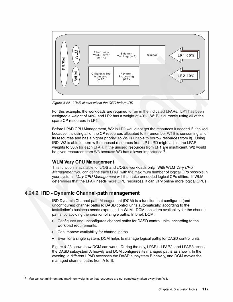
Figure 4-22 LPAR cluster within the CEC before IRD
For this example, the workloads are required to run in the indicated LPARs. LP1 has been assigned a weight of 60%, and LP2 has a weight of 40%. W1B is currently using all of the spare CP resources in LP2.
Before LPAR CPU Management, W2 in LP2 would not get the resources it needed if it spiked because it is using all of the CP resources allocated to it (remember W1B is consuming all of its resources and has a higher priority, so W2 is unable to borrow resources from it). Using IRD, W2 is able to borrow the unused resources from LP1. IRD might adjust the LPAR weights to 50% for each LPAR. If the unused resources from LP1 are insufficient, W2 would be given resources from W3 because W3 has a lower importance.61
WLM Vary CPU ManagementThis function is available for z/OS and z/OS.e workloads only. With WLM Vary CPU Management you can define each LPAR with the maximum number of logical CPs possible in your system. Vary CPU Management will then take unneeded logical CPs offline. If WLM determines that the LPAR needs more CPU resources, it can vary online more logical CPUs.
4.24.2 IRD - Dynamic Channel-path managementIRD Dynamic Channel-path Management (DCM) is a function that configures (and unconfigures) channel paths to DASD control units automatically, according to the installation’s business needs expressed in WLM. DCM considers availability for the channel paths, by avoiding the creation of single paths. In brief, DCM:
� Configures and unconfigures channel paths for DASD control units, according to the workload requirements.
� Can improve availability for channel paths.
� Even for a single system, DCM helps to manage logical paths for DASD control units
Figure 4-23 shows how DCM can work. During the day, LPAR1, LPAR2, and LPAR3 access the DASD subsystem A heavily and DCM configures its managed paths as shown. In the evening, a different LPAR accesses the DASD subsystem B heavily, and DCM moves the managed channel paths from A to B.
61 You can set minimum and maximum weights so that resources are not completely taken away from W3.
PR/S
M
WLM
WLM E lec tron ics
W eb S erver (W 1A)
Shipm ent Tracking (W 3) U nused
C h ild ren 's Toy W ebse rver
(W 1B)
Paym ent P rocessing
(W 2)
LP1 60%
LP2 40%
Chapter 4. Discussion topics 117

Note that at least one channel path to each DCM-managed control unit should be a static path—not under DMC control. Since DCM does not have any I/O-related activity data during a startup phase, no paths will be configured by DCM.
Figure 4-23 DCM concepts
As Figure 4-23 shows, each channel path managed by DCM must be connected through an ESCON director.
Be aware that the channel paths managed by DCM cannot be shared with the images outside the LPAR cluster, even if the CHPIDs themselves are defined as SHARED in HCD or IOCP statements. DCM-managed CHPIDs are owned by an LPAR cluster.
4.24.3 IRD - Channel Subsystem Priority QueuingWith Channel Subsystem (CSS) Priority Queueing, I/O requests are queued according to a priority determined by WLM. Without this function, I/O requests queued in CSS are handled in a first-in, first-out manner. This sometimes causes higher importance work to be delayed.
When an I/O request is received, WLM sets a UCB/CU I/O priority and a CSS priority for the request. This priority is then adjusted by the CSS, based on parameters set through SE or HMC interfaces. The complete process is a little too detailed for this redbook and we will not attempt to describe it here. The result is I/O response that better matches the intentions of the system owner. In particular, the ability of a lower-importance function to dominate the I/O capacity of shared devices can be controlled.
CSS Priority Queueing can be used for entire zSeries system, whether or not the partitions involved belong to LPAR clusters.
LPARX LPAR1 LPAR3LPAR2 LPARZ
LPAR Cluster IRDGRP
DASDControl Unit
DASDControl Unit
LPARX LPAR1 LPAR3LPAR2 LPARZ
LPAR Cluster IRDGRP
DASDControl Unit
DASDControl Unit
ESCONDirectors
112
2
3
45
678
9
10
11 112
2
3
45
678
9
10
11
ESCONDirectors
IRD DCM Concept
2 Managed CHPIDs 2 Managed CHPIDsStatic Static Static Static
A B A B
118 Technical Introduction: IBM zSeries 800

4.24.4 IRD - non-z/OS partitionsIRD can manage CPU resource for non-z/OS62 LPARs; this includes Linux LPARs, for example. Only the LPAR Weight Management function is available for non-z/OS images, although all IRD functions are available for any z/OS or z/OS.e LPARs that may be in the same LPAR cluster. z/OS images must be at least z/OS V1R2, or z/OS.e. in order to help manage non-Z/OS/e LPARs.
Non-z/OS partitions cannot manage IRD. For non-z/OS partitions, the associated LPAR cluster name is defined in the image profile. The z/OS that is providing the management functions must be in the same LPAR cluster. The management provided for the non-z/OS partition is rather basic and is related to velocity goals defined in WLM. Individual workloads in the non-z/OS system cannot be managed.
4.24.5 Requirements for IRD functionsThe following are required for IRD to function:
� Hardware
– zSeries processor
IRD only works on zSeries processors, z800 or z900 in 64 bit mode.63 WLM CPU Management functions are only work for LPARs whose logical CPs are defined as shared CPs. LPARs with dedicated CPs or IFLs cannot be managed.
– CF at CFCC level 9 or higher
CFCC level 9 is required for the WLM IRD CF structure. A WLM IRD CF structure should be allocated on a CF, which is at CFCC level 9 or later64, for each zSeries processor using IRD functions except for the following, which do not require CF structures:
• Channel Subsystem Priority Queueing• DCM for z/OS or z/OS.e running on zSeries in basic mode (not LPAR mode)• DCM for z/OS or z/OS.e running as Monoplex (PLEXCFG=MONOPLEX in
IEASYSxx Parmlib member, single system sysplex by its definition)
– ESCON directors (only for DCM)
ESCON directors are required for DCM. Other IRD functions do not need ESCON directors. For DCM, ESCON directors must be at least the following microcode levels:
• 9032-002 at Version 4 Release 1• 9032-003 at LIC 04.03.00• 9032-005 at LIC 05.04.00
– DASD control units (Only for DCM)
This requirement is only for DCM. DCM works with the following IBM DASD control units:
• IBM 2105 Enterprise Storage Server (ESS) with microcode level SC01208• IBM 9393 RAMAC Virtual Array
62 z/OS.e is considered as a part of z/OS here.63 According to the terms and conditions of z/OS and z/OS.e, you are not allowed to operate in 31 bit mode on zSeries processors. Thus all z/OS and z/OS.e images on zSeries processors must be in 64 bit mode. 64 CF level 9 or later is available for zSeries and 9672 G5/G6 processors only. Thus a WLM IRD CF structure must be allocated in the CFCC LPAR running on one of those processors.
Chapter 4. Discussion topics 119

All paths for DASD control units which are managed by DCM must not be shared with other control units, including DASD control units not managed by DCM. That is, do not mix channel paths for managed DASD control units with other control units, even though the paths themselves are not managed ones. Otherwise, DCM will not work.
� Software
– z/OS V1R1 or later (or z/OS.e)
In order to manage non-z/OS images, all z/OS images must be z/OS V1R2 or later, or z/OS.e.
For Channel Subsystem Priority Queueing, only z/OS or z/OS.e images can prioritize workloads into multiple priorities within each image. Workloads in each image are set to have a fixed priority which is set at HMC/SE as the minimum for that image.
– WLM Goal mode
Operating in WLM Goal mode is required for IRD CPU Management. z/OS images in WLM Compatibility mode cannot be managed by IRD.
In WLM compatibility mode, DCM tries to equalize performance over all DASD control units, not based on workload importance. In order to manage paths according to workload importance, all z/OS or z/OS.e systems65 in the LPAR cluster must be in WLM Goal mode.
For Channel Subsystem Priority Queueing, Operation in Goal mode is not required. However, it is required in order to prioritize workloads within a single image. Otherwise, all workloads in an LPAR image have the same fixed priority defined as the minimum priority at the HMC/SE.
4.24.6 IRD setup tips for z8001. WLM LPAR cluster CF structure
The WLM LPAR cluster structure name is SYSZWLM_sssstttt, where ssss are the last 4 hexadecimal digits of the processor serial number, and tttt is the model type of the processor. For z800, the model type is 2066. To see the processor serial number and the model number portion of the name, enter the Display M=CPU operator command:
D M=CPU IEE174I 01.43.32 DISPLAY M 790 PROCESSOR STATUS ID CPU SERIAL 0 + 051CE32066 1 + 151CE32066 2 - CPC ND = 002066.003.IBM.02.000000011CE3 CPC SI = 2066.003.IBM.02.0000000000011CE3 CPC ID = 00 + ONLINE - OFFLINE . DOES NOT EXIST W WLM-MANAGED CPC ND CENTRAL PROCESSING COMPLEX NODE DESCRIPTOR CPC SI SYSTEM INFORMATION FROM STSI INSTRUCTION CPC ID CENTRAL PROCESSING COMPLEX IDENTIFIER
For our z/OS system running on z800, the response from the Display M=CPU command is shown above and our WLM LPAR cluster structure name is SYSZWLM_1CE32066.
65 If an OS/390 image exists in the LPAR cluster, the OS/390 image need not to be in WLM Goal mode. An OS/390 image cannot be managed by IRD, so it is outside the scope of IRD.
120 Technical Introduction: IBM zSeries 800

The WLM LPAR cluster structure is a system-managed structure. That is, the CFRM CDSs must be formatted with ITEM NAME(SMREBLD) NUMBER(1) in order to process a system-managed rebuild later. The following command can be used to display this information:
D XCF,COUPLE,TYPE=CFRMIXC358I 22.11.26 DISPLAY XCFCFRM COUPLE DATA SETSPRIMARY DSN: SYS1.ADCDPL.CFRM.CDS01 VOLSER: Z2RES2 DEVN: 0339 FORMAT TOD MAXSYSTEM 01/31/2002 01:56:02 8 ADDITIONAL INFORMATION: FORMAT DATA POLICY(6) CF(8) STR(50) CONNECT(32) SMREBLD(1)ALTERNATE DSN: SYS1.ADCDPL.CFRM.CDS02 VOLSER: Z2RES2 DEVN: 0339 FORMAT TOD MAXSYSTEM 01/31/2002 01:57:43 8 ADDITIONAL INFORMATION: FORMAT DATA POLICY(6) CF(8) STR(50) CONNECT(32) SMREBLD(1)CFRM IN USE BY ALL SYSTEMS
If SMREBLD(1) appears in the response, then system-managed rebuilds can take place. To change your structure allocation, you need to reallocate and format the CFRM CDSs with the IXCL1DSU format utility and specify ITEM NAME(SMREBLD) NUMBER(1) in the parameters.
The next step is to define WLM LPAR cluster structure SYSZWLM_1CE32066. The initial size (INITSIZE) for the structure is set to6144 KB, which may be sufficient for both LPAR CPU Management and DCM functions. We set 12288 KB for SIZE, twice as large as INITSIZE; this is the standard recommendation for SIZE. In order to allow automatic alteration if the structure utilization goes up, ALLOWAUTOALT(YES) must be specified. Automatic alter adjusts the structure size according to its utilization, within the range of MINSIZE to SIZE. To ensure that the structure size is at least 6144KB, we set MINSIZE(6144).
//IXCMIAPU JOB MSGCLASS=H,MSGLEVEL=(1,1),CLASS=A// EXEC PGM=IXCMIAPU//SYSPRINT DD SYSOUT=*//SYSABEND DD SYSOUT=*//SYSIN DD * DATA TYPE(CFRM) REPORT(YES) DEFINE POLICY NAME(IRDPOL) REPLACE(YES)
..... STRUCTURE NAME(SYSZWLM_1CE32066) SIZE(12288) INITSIZE(6144) MINSIZE(6144) ALLOWAUTOALT(YES) PREFLIST(CFCC1,CFCC2)/*
After putting our new CFRM policy, IRDPOL, in the CFRM CDSs, we can start this policy by entering the following operator command:
SETXCF START,POLICY,TYPE=CFRM,POLNAME=IRDPOL
2. WLM Goal Mode settings
Chapter 4. Discussion topics 121

To invoke the WLM ISPF application to define a WLM policy, enter the following TSO/E command:
EXEC ‘SYS1.SBLSCLI0(IWMARIN0)’
If RACF does not permit you to access the WLM ISPF application, ask your RACF administrator to give you access. The required RACF commands will be something like the following:
RDEFINE FACILITY MVSADMIN.WLM.POLICY UACC(NONE)PERMIT MVSADMIN.WLM.POLICY CLASS(FACILITY) ID(your_userid) ACCESS(UPDATE)SETROPTS CLASSACT(FACILITY) RACLIST(FACILITY) REFRESH
In the PERMIT command, ACCESS(UPDATE) is needed to change the WLM policy. If you only need to see the definition, ACCESS(READ) is adequate.
– For CSS Priority Queueing: multiple priorities within an image
To utilize multiple CSS priorities within an image, I/O priority management must be Yes in the WLM policy. In the WLM ISPF application, Definition Menu -> 8. Service Coefficients/Options produces the panel that contains this parameter.
After setting this, you must install the definition and then activate the policy. To do this, follow the path Definition Menu -> Utilities -> 1. Install definition / 3. Activate service policy.
– For LPAR Weight Management for non-z/OS partitions
WLM service class definition for subsystem type SYSH is required. To define service class and SYSH subsystem type:
• Select Definition Menu -> 4. Service Classes.• Put 1 (Create) in any Action field.• Enter Service Class Name, Description (optional), and Workload.• Put I (Insert new period) in the Action field and select 3. Execution velocity.• Set Velocity, Importance for the Linux partitions.
Repeating the last three steps, you may assign different velocity goals for each non-z/OS system.
• Go back to the Definition Menu.• Select 6. Classification Rules.• Put 1 (Create) in any Action field.• Type SYSH in the Subsystem Type field, and the service class name defined above in
the default service class.• Put I (Insert rule) in the Action field and enter your classification rules.• You can specify PX (Sysplex name), SY (sysname), or SYG (sysname group) for
Qualifier Type.
After setting these parameters, you must install the definition and then activate the policy. To do this, follow the path Definition Menu -> Utilities -> 1. Install definition / 3. Activate service policy.
3. MVS parameter settings (for WLM Vary CPU Management only)
WLM Vary CPU Management is defaulted to be active. If you do not want to use this function, you must specify VARYCPU=NO in your IEASYSxx parmlib member, since the default value is VARYCPU=YES. You can change this parameter dynamically by the operator command SET OPT=xx, pointing to an IEAOPTxx member in which VARYCPU=NO is specified.
4. HMC/SE profile settings
– To enable LPAR CPU Management, you must set LPAR parameters at HMC, as follows:
122 Technical Introduction: IBM zSeries 800

• Log onto the HMC as SYSPROG. (Default password for SYSPROG is “password”.)• Find the CPC Operational Customization task list.• Double-click the Groups icon in the Views area.• Double-click the Defined CPCs icon in the Work area.• Drag and drop the icon representing your CPC to Change LPAR Controls in the
Task area.• Check the WLM Managed check box for each LPAR in the LPAR cluster.• Specify Initial processing weight, Minimum processing weight, and Maximum
processing weight for each partition. 1 to 999 can be specified for each value. Note that the weight values are not percentages.
• Insure Initial capping is not checked for each partition in the LPAR cluster.• Click Save and change on the bottom.• Click OK.
– To enable DCM, you must also enable the dynamic I/O configuration-related functions at the HMC as the following steps:
• Log onto the HMC as SYSPROG. (Default password for SYSPROG is “password”.)• Find the CPC Operational Customization task list.• Double-click the Groups icon in the Views area.• Double-click the Defined CPCs icon in the Work area.• Drag and drop the icon representing your CPC to Customize/Delete Activation
Profiles in the Task area.• Select a reset profile and click Customize in the bottom of the Customize/Delete
Activation Profile List window. Generally, the reset profile previously assigned for the CPC icon (object) is chosen by the default.
• Click the Dynamic tab in the bottom of the window.• Check Allow dynamic changes to the channel subsystem input/output (I/O)
definition, and specify a value within 1-100 for Percent of input/output configuration (IOCDS) expansion allowed. If you are not familiar with this value, 50 might be appropriate for the first use.
• Click the Options tab in the bottom of the window.• Check the Automatic input/output (I/O) interface reset check box.• Click on each LPAR partition tab on the right of the window, click the Security tab
on the bottom, then check the Input/output (I/O) configuration control check box.• Click Save on the bottom.• Click OK. • If the IOCDS assigned to the reset profile was not generated by HCD, you may
receive the message Do you want to select a different IOCDS or change the ‘Allow dynamic changes...’ selection? Press No if you want to save your changes.
• Return to the Customize/Delete Activation Profile List window and click Cancel to exit.
– To enable CSS Priority Queueing, do the following:
• Log onto the HMC as SYSPROG. (Default password for SYSPROG is “password”.)• Find the CPC Operational Customization task list.• Double-click the Groups icon in the Views area.• Double-click the Defined CPCs icon in the Work area.• Drag and drop the icon representing your CPC to Enable I/O Priority Queuing in the
Task area.• Click Enable in the Global input/output (I/O) priority queuing dialogue box, then
click OK.• Click OK.• Drag and drop the icon representing your CPC to Change LPAR I/O Priority
Queuing in the Task area.
Chapter 4. Discussion topics 123

• Specify Minimum input/output (I/O) priority and Maximum input/output (I/O) priority for each partition. The value range is 0-15.
• Click Save.• Click OK.
– For non-z/OS LPAR Weight Management, define the LPAR cluster name from which the weight is controlled:
• Log onto the HMC as SYSPROG. (Default password for SYSPROG is “password”.)• Find the task list.• Double-click the Groups icon in the Views area.• Double-click the Defined CPCs icon in the Work area.• Drag and drop the icon representing your non-z/OS partition (LPAR) to
Customize/Delete Activation Profiles in the Task area.• Select an image profile and press Customize in the bottom of the
Customize/Delete Activation Profile List window. Generally, the image profile previously assigned for the CPC image icon (object) is chosen by the default.
• Click the Options tab on the bottom of the window.• Enter the Sysplex name from which the partition is managed in CP management
cluster name, and press Save.• Press Yes for the Do you want to continue with the save? message.• After you have defined the LPAR cluster name for non-z/OS partition, you must
deactivate and reactivate the partition to reflect the change.
5. To enable non-z/OS LPAR Weight Management for SuSE Linux, install a kernel module and pass a system name parameter to it:
cd /lib/modules/2.4.7-SuSE-SMP/kernel/drivers/s390/char/insmod hwc_cpi.o system_name=sysname
The name of the directory, 2.4.7-SuSE-SMP, may vary according to your Linux distribution, kernel version, or environment. Once the system name is set, reboot Linux to reflect the changes.
We did not try this function and strongly recommend that you consult appropriate SuSE sources for more information.
4.24.7 Operating considerations� IRD does not attempt to manage logical CPs that are manually varied offline by operator
commands. These offline logical CPs do not automatically come online again until you issue VARY ONLINE operator commands. The same is also true for reserved CPs, which are prepared for future upgrades. You must enter VARY ONLINE commands to use additional CPs added by an upgrade.
� If you want to IPL a non-z/OS operating system (probably OS/390) in the same partition where z/OS in an LPAR cluster was running, you must deactivate and reactivate the partition before the IPL. Otherwise, the CPs that were placed offline by IRD (while z/OS was running) will not come online.
� If you switch WLM to Compatibility mode, the CPU weight and the number of logical CPs for that image are reset to the initial values. This may cause weights for other images in the LPAR cluster to change and may affect their performance.
124 Technical Introduction: IBM zSeries 800

4.25 Hardware data compression Both the z800 and z900 families have the CMPSC hardware instruction that performs data compression. While it is possible for an application program to use this instruction directly, normal usage is by system access methods and subsystems. It can be used by the following system functions:
� DB2 for data tables and log data
It cannot be used for various DB2 control functions, including indexes, directories, catalogs, and so forth.
� IBM for data
It cannot be used for IMS control information.
� VSAM for KSDS data sets
It cannot be used for other types of VSAM data sets and there are minor restrictions for use within KSDS data sets.
� QSAM (and BSAM) for extended format data sets
� VTAM for some data fields
Appropriate use of data compression can often reduce the disk space required for the data by around 50%; the savings typically range from 40-70%. The CMPSC instruction in the z800 and z900 is implemented through special hardware. (Earlier systems used microcode for this instruction.) The current hardware implementation offers considerably better performance than what was available on earlier systems.
Chapter 4. Discussion topics 125

126 Technical Introduction: IBM zSeries 800

Chapter 5. Frequently asked questions
This chapter reviews common questions we encountered in the early phases of our z800 usage.
Migration and UpgradesQ: How do I convert the DEVMAP from my MP3000 to something on the z800?A: There is no equivalent to a DEVMAP on the z800. The DEVMAP relates to emulated I/O operation and there is no emulated I/O on a z800.
Q: Can I connect to the integrated disks in my MP3000? This would make migration easier.A: Sorry, there is no way to make a direct connection to these disks.
Q: Can I use a z800 in an office environment? We did not have a raised floor for our MP3000.A: Maybe, but we do not recommend it. It is not very practical if you have a large number of channel connections. If you have a small number of channel connections (and LAN connections), and if you can supply sufficient cool air (up to 16000 BTUs), then it should work. However, remember that a typical MP3000 is self-contained, with internal disks, while a z800 is not self-contained. Your office environment would probably need to accommodate external disk and tape drives (with their cable and cooling requirements) in order to install a complete z800 system.
Q: IBM seems to make a big deal of the non disruptive upgrade functions, including CBU. As I understand it, all a disruptive upgrade involves is an IPL. Is this correct?A: Yes, you are correct. However, in some environments an IPL needs to be planned well in advance, and nondisruptive changes are important in these installations. A third category of upgrades (memory or crypto coprocessors on the z800) requires the system to be shut down.
Q: Can I upgrade from a Linux 0LF model to an 0CF model or a General Purpose model? A: Upgrade paths from Linux 0LF models to General Purpose and 0CF models are not supported.
Q: Can I upgrade from a General Purpose model to an 0CF or Linux 0LF model? A: Upgrade paths from General Purpose models to Linux OLF models and 0CF models are not supported.
5
© Copyright IBM Corp. 2002 127

Q: Can I upgrade from an 0CF to an Linux 0LF or a General Purpose model? A: Upgrade paths from 0CF models to Linux 0LF models are not supported. Upgrades from 0CF models to General Purpose Models are supported.
z/OS.e and z/OSQ: What happens under z/OS.e if I run an old application that was compiled by COBOL?A: If the version of COBOL used LE run-time functions, the program will fail with a message about Not supported in this environment. If the program does not use LE, it might work. However, your license for z/OS.e prohibits running the program.
Q: What happens under z/OS.e if I run an ISV application and, unknown to me, it was written in COBOL?A: If it uses the COBOL LE run-time functions, the program will fail. Otherwise, it may work. You should verify with your software suppliers whether their products meet the license requirements for z/OS.e
Q: Are third-party applications available for z/OS.e?A: Yes, at the time of writing many vendors were testing their products under z/OS.e.
Q: Should I apply general z/OS service to z/OS.e?A: In general, yes. This may apply service to portions of z/OS code that are disabled in the z/OS.e environment, but this should not hurt anything and simplifies the maintenance process.
Q: Can a z/OS.e system share disks with a full z/OS system without violating the z/OS.e license agreement?A: Yes.
Q: We might need to run a very old operating system we keep in reserve. Can the z800 run in S/370 mode?A: No.
Q: What are the different types of software pricing?A: Some of the common terms are:
zELC - zSeries Entry Level ChargesPSLC - Parallel Sysplex License ChargesWLC - WorkLoad ChargesEngine-Based Monthly License ChargesMLC - Monthly License ChargesOTC - One-Time Charges (or Engine-Based One-Time Charges)MSU - Million Service UnitsGOLC - Graduated One-time License Charges
Not all of these apply to a z800. Software pricing on all large systems has become complex. Your marketing representative can help you select the pricing model to minimize your software costs.
Q: I am running a simple z800 (no Parallel Sysplex) and want to use z/OS.e. Must I allow my system to call home to IBM?A: In general, yes.
Q: I will have shared DASD between z/OS.e and my full z/OS. Can I STEPLIB to COBOL or other LE functions from the z/OS.e side?A: This would violate the terms of your z/OS.e license.
128 Technical Introduction: IBM zSeries 800

HardwareQ: My z800 machine included something that looks like a spare terminator for the STI ports on the back of the processor cage. It is part number 11P0360. What should I use this for?A: This is a wrap plug, not a terminator. It is used in conjunction with diagnostics for an ICB-3 cable. (ICB-3 is one of the interfaces used for Coupling Facility channels.) Keep this wrap plug together with the other wrap plugs shipped with the machine.
Q: I have a z800 model 002. Can I “rotate” which PUs I use, so that the spare PUs are regularly used?A: No, there is no provision for this.
Q: How is the spare ESCON port used?A: The 16-port ESCON cards reserve one port as a spare. By default it is the last port (connection J15) on the card. (Actually, any unactivated port on the ESCON card can be used as a spare.) The switchover process, in case of a failure, is not automatic. The Repair&Verify procedure directs the IBM Service Representative to manually move the ESCON cable from the failed port to the newly-activated port. The CHPID mapping function can be used to determine which spare port was activated to replace a failed port.
Q: What happens if the SAP processor fails and I have no spare PUs?A: The system will halt one of the other PUs and use it as a SAP processor. The result is that you are left with one CP/IFL/ICF less than you should have, and IBM will schedule service as soon as possible.
Q: You have not mentioned the Hardware Storage Area. Does it exist on a z800? How large is it?A: Yes, HSA exists. The size is not significant, considering that the smallest z800 has 8 GB memory. z800 HSA does not contain a disk cache like the one in an MP3000, and it was the disk cache that usually made the MP3000 HSA size significant. The z800 HSA size depends on the number of LPARs in use, and ranges from 160 MB (basic mode) to 192 MB (LPAR mode). Extensive I/O configurations may require a larger HSA.
Q: Is the z800 “big endian” all the time? Even when running Linux?A: Yes.
Q: Can the z800 use both EBCDIC and ASCII?A: Yes. This is mostly a software issue. EBCDIC is “built in” for a few machine instructions related to numeric conversions and packed decimal data. It is also implicit in devices that are obviously character-oriented, such as printers and terminals. Otherwise, the z800 hardware (or any S/360, S/370, S/390, or z/Architecture machine) does not care whether the software uses ASCII or EBCDIC or a mixture of both.
Q: My MP3000 has a 4mm tape drive. Does the z800 have a 4mm tape drive? Can a 4mm tape drive be attached in some reasonable way?A: Not at this time. However, you might note that an Open Fiber Channel Protocol (FCP) Statement of Direction is associated with the z800 announcement. An FCB interface leads to the attachment of SCSI devices. The SCSI connection potentially could include tape support, and 4mm tape drives are SCSI devices.
Q: Where can I find more details about SCSI connections for the z800?A: At the time of writing, the only information available was the Statement of Direction for the Open Fiber Channel.
Chapter 5. Frequently asked questions 129

Q: My machine included several VP or VPD diskettes and envelopes. What are these?A: These are intended to transmit Vital Product Data to IBM. If your system has the normal call home functions, you do not need these diskettes or mailers. If your system does not use a call home function (due to security concerns, perhaps), you should create a VPD diskette if you change the hardware configuratio, and then mail the diskette to IBM. There is an HCD icon to Transmit VPD (and this can be used to create the diskettes).
Q: There is a large power switch on the front panel. Is this the normal on/off switch?A: No. This is the Emergency Power Off (EPO) switch and is not normally intended as a simple power switch. However, we notice that it is frequently used as a power switch. If you use this switch to remove power from the z800, you will notice that you cannot turn power on again with the switch. This is a typical function of an EPO system, where it is necessary to reset the EPO function after it is used. To reset the EPO on the z800, it is necessary to reset two circuit breakers in the back of the system. This is illustrated in Figure 5-1 on page 130.
Figure 5-1 EPO Reset
This area of the z800 is considered a service area and IBM recommends that only qualified service personnel access this area of the machine.
Q: Some very strange tools were included with my shipment, but were not in the special tool box. What might these be?A: These tools to remove or install the cryptographic coprocessors.
Q: If I open the back cover of a small z/800, I notice that there are no cables going to the back part of the I/O cage. Can I add I/O cards to this part of the I/O cage?A: A “small” system using fewer than eight I/O cards will have all the I/O cards in the “front” side of the I/O cage. The “rear” side of the I/O cage is not connected to anything. In this state there are four unused STI interfaces (assuming you have not used them for ICB connections). The STI-M card(s) and cable(s) are ordered automatically if you expand your z800 beyond eight I/O cards.
Linux and IFLsQ: What is the technical difference between a 2066-001 and a 2066-0FL with a single engine? In other words, what is unique about the Linux-only models?A: A Linux IFL (whether in normal models or the 0FL model) cannot successfully IPL z/OS (or any earlier versions of MVS, OS/390, VSE/ESA, and so forth). Unique functions used by z/OS early in the IPL process are not available in an IFL.
Bottom rightcorner on theback of the z800
Small double CB; must be reset(under a protective metal cover)
Large double CBs; do not touch
LEDs. Top three usually green.
Main powercable connections
130 Technical Introduction: IBM zSeries 800

Q: Exactly what functions or instructions are missing in an IFL to prevent MVS from running?A: IBM does not document this.
Q: I understand I can run VM with an IFL engine. Can I run full VM facilities, such as VTAM operation, compilers, batch emulation, and so forth?A: No. Only a subset of VM capabilities can be used. The subset includes CMS, but excludes VTAM, compile and link operations, batch operation, and a number of other functions. DIRMAINT, VMPRF, RTM, and parts of RSCS (LPR, LPD) may be used. Some products with usage-based licenses may be used. In general, the intention is to limit VM functions to those reasonably needed to manage a Linux environment.
Q: Can I run z/OS.e in an IFL?A: No.
Q: Is there a special LPAR or PU, similar to an IFL, for running z/OS.e?A: No.
Q: Is the Linux Offering machine exactly the same as the general purpose z800?A: The base processors (PUs) are exactly the same. The system has the obvious differences. The Linux-only offering contains only IFL PUs for example, and offers only those additional features and I/O adapters that are usable in a Linux-only (or Linux under VM) environment. See “IBM zSeries Offering for Linux” on page 5 for more details.
Q: Can I convert the Linux Offering z800 into a general purpose model?A: No.
Q: Can I run both 32-bit and 64-bit versions of Linux? At the same time?A: Yes, provided you have the appropriate Linux distributions. You can do this under z/VM or by using separate LPARs or with a combination of z/VM and LPARs.
Q: Can a Linux system share disks with z/OS or z/OS.e?A: For practical purposes, no. The most recent versions of Linux produce a disk label format that z/OS can tolerate, but there is no useful sharing of data at this time.
Q: Can I boot a Linux CD-ROM from the SE or HMC of a z800?A: Yes, you can boot it from the HMC. We installed Linux using this method. Note that this only boots (and installs) a Linux ramdisk. You will still need a source (such as an external ftp server) to supply the Linux modules needed to install Linux on your disks.
Q: Does Linux on the z800 use ASCII or EBCDIC?A: ASCII.
Q: I am still confused about Linux for the z800. Where do I get it?A: Not from IBM. At the time of writing, there are three mainline “commercial” Linux distributions that can be used with the z800. These are from SuSE, Red Hat, and Turbolinux. Several other organizations, such as Marist College, offer prebuilt Linux packages that can be used with the z800. You can also download all the source code (and patches) and build your own Linux kernel. IBM sells middleware, such as DB2, that can be installed on top of these Linux distributions.
I/O and cablingQ: I cannot find the feature codes to order cables for the z800. Where are they?A: They do not exist. Cables have become sufficiently complex that ordering by simple feature codes does not work very well. IBM uses a services offering to provide cables for the z800.
Chapter 5. Frequently asked questions 131

Q: Our local “experts” talk about Passat and Cargo and Compatibility I/O cages and I find this confusing. Does the z800 have these?A: No. These were development names for z900 I/O cages. The Passat holds “old” adapters such as parallel channels and OSA-2 adapters; it is sometimes known as a Compatibility cage. The Cargo cage holds the newer adapters (such as are also used with the z800). During development, the z800 I/O cage was known as Cargo Lite; it is similar to the z900 Cargo cage, but smaller in some respects. These names were used during product development stages and are no longer meaningful.
Q: I have acquired several old IBM 9034 (“Pacer”) boxes. Can I use these to attach parallel channel devices?A: Yes.
Q: Can I use the Optica converters with z900 systems? With older S/390s?A: Yes, as far as we know they should work with any ESCON channel. However, be aware that byte multiplexor devices may be a special case. You should obtain the latest information from Optica.
Q: Can I purchase ESCON and other fiber cables from non-IBM suppliers?A: Yes, but make certain you get the right cables and the right connectors. The number of cable types and connectors has grown rapidly.
Q: Do I need conversion cables on both ends of my existing ESCON cables?A: No. One end of your existing ESCON cable will still plug into your existing ESCON control unit or Director. You do need an MCP “conversion” cable at both ends of a multimode fiber that is connected to long-wave (LX) channels and devices; this is not related to ESCON channels.
Q: Should I stack the Optica converters under the floor? How should I arrange them?A: Arrange them any way that is convenient, but provide some air flow around the units. You probably want to avoid major movements of existing parallel channel cables and this will be the determining factor in placement.
Q: Can I use the Optica converters to connect a parallel channel to an ESCON control unit?A: No. They provide a one-way conversion for connecting ESCON channels to parallel control units. (The same is true for the Pacer units.)
Q: The emulated I/O LAN interfaces on my MP3000 have been a bottleneck sometimes. Are the z800 LAN interfaces faster?A: Yes, they are much faster than the emulated I/O interfaces.
Q: I am a little confused about using my existing channel cables. Can you summarize the situation?A: Cabling, especially for a large system, has become sufficiently complex that IBM has moved to the Services Offering (as announced with the z800) as a method of determining exactly what cables you need and then ordering the right ones. As a very brief summary:
– Existing parallel channels may be used, but only if you purchase converter boxes. You must use ESCON connections from the z800 to the converter boxes.
– Traditional ESCON cables (with the large duplex connector) cannot be connected to the z800. You need a conversion kit from the new connector (used with z800 and z900 machines) to the traditional ESCON cable connector. Alternately, you could purchase new ESCON cables with the appropriate connectors. The control unit end of an ESCON cable still uses the large duplex connector.
– The earlier FICON cables (SC connectors) do not connect to the z800. A conversion kit is available to use these cables.
The conversion kits may be obtained as part of the Services Offering.
132 Technical Introduction: IBM zSeries 800

CryptoQ: I want to directly program the cryptographic processors using assembly language. Where are the instructions documented?A: IBM does not document the instructions used to control these processors. The only documented interfaces are to the ICSF functions. (ICSF is part of z/OS and provides APIs to use the cryptographic hardware.)
Q: Why do I need the cryptographic coprocessors in order to install the cryptographic PCICC cards?A: z/OS software requires the coprocessors for key management. A Linux-only z800 (model 0LF) is a special case. For this model only, you can order PCICA cryptographic cards without having the cryptographic coprocessors installed.
Q: I want to use the cryptographic hardware for SSL processing. I am still confused by the TKE hardware. Do I need it?A: Probably not. In general, if you are in an environment (usually involving large inter-bank transfers) that needs a TKE, your organization will already know about TKEs.
Q: Somebody said that the crypto processors lose their initialization and master keys if the MCM is removed (for a memory upgrade, for example). Is this true?A: Yes. The connection to the batteries that maintain cryptographic coprocessor contents is lost if the BPU-PK is removed. You will need to reinitialize it. Basic initialization will require the two cryptographic diskettes that were shipped with the z800 (assuming you ordered the cryptographic coprocessors, of course). You should be prepared to do this and to re-enter your master keys before taking the machine down for an upgrade or repair that involves removing the BPU-PK.
2074 and 3174Q: The salesman says I must purchase a 2074 to go with a z800. Is this correct?A: Not exactly. If you intend to run any of the traditional S/390 operating systems (that is, anything except Linux), then you need a “local, DFT, channel-attached, non-SNA” control unit for 3270 consoles.1 For practical purposes, you have two choices for these display control units: 3174s and 2074s. IBM no longer manufactures 3174s, but there are many in use and they are commonly available on the used-equipment market. (Remember that a parallel channel model will require an ESCON converter.)
Again, for practical purposes, you will need one 3174 for each LPAR you use.2 In contrast, a single 2074 can provide consoles for many LPARs. Assuming you will have several LPARs, you choice is a single 2074 or multiple channel-attached non-SNA 3174 control units. If you already have enough 3174s, you could use them and skip the 2074. If you are planning a new installation—with no existing 3174s—you could buy them on the used-equipment market or simply buy a 2074. We suggest that a new installation should not add to their complexity by involving unknown, used equipment.
Linux does not use either the 2074 or the 3174s. It does not use 3270 terminals at all. However, Linux under VM is a slightly different story. In principle, you might manage VM using only the Operating System Messages window in the Support Element, but we suggest this is not a reasonable solution for most installations. In other words, if you plan to use VM, you will probably need either a 2074 or 3174s (one for each LPAR).
1 In principle, you can run a production-ready z/OS using only the Operating Systems Messages window in the Support Element plus VTAM or TSO consoles. However, if your installation has the skills to manage this mode of operation, you would not be asking this question.2 This excludes any LPARs used directly for Linux. Linux has no use for 3270 devices. VM (which might be used to host multiple Linux images) is best managed through a 3270 interface.
Chapter 5. Frequently asked questions 133

If you use 3174s, you will need several “real” coax-attached 3270 terminals. If you use a 2074, you will need several PCs running TN3270e client software. (And this must be TN327e and not TN3270.)
Q: Does z/OS.e change the requirement for a 2074 or 3174 control units?A. No. In this respect it is exactly like full z/OS.
Q: Can a single 2074 be used with more than one S/390 machine?A: Yes. This normally involves the use of an ESCON Director.
Q: My salesman insists that I order two 2074s. Is this reasonable?A: Probably. A z800 is a high-availability system, with practically every element backed up by a redundant copy of the element. A single 2074 (even with two ESCON adapters) has little redundancy and could be a weak link in the total system. However, there are alternate recovery paths that might be suitable in some circumstances. In particular, you can configure z/OS so that the software console function in the Support Element (or HMC) provides a limited backup for operator sessions normally connected through a 2074. If this provides sufficient redundancy for your planned 2074 use, then you might consider only one 2074. This planning is not as simple as it sounds and we suggest you discuss the situation with a knowledgeable system architect before making a final decision.
MiscellaneousQ: What is the difference between 32-bit and 31-bit operation?A: They are the same. In this mode the registers are 32 bits long, but the maximum address is restricted to a 31-bit number. This design arose from compatibility concerns with programs using 24-bit addressing. The z800 can use 24-, 31-, or 64-bit addressing modes; it uses 32- or 64-bit general purpose registers.
Q: I cannot find the feature code or price for Hipersockets. Why?A: They are basic parts of the system. No feature codes (or prices) are involved.
Q: I have an existing Ethernet structure that I want to use for SEs and HMCs. Can I use thin-wire (coax) Ethernet?A: No. Neither the SEs nor the HMCs have provisions for attaching Ethernet coax or external Ethernet transceivers.
Q: Can I control my z800 from home, using the SE or HMC Web interfaces?A: There are several factors here, and the first is security. Do you want your system exposed on the Internet such that a simple userid/password is the only thing that prevents someone from taking over your machine? Assuming you accept the risk, there are two levels of Web control possible. The first level is a HMC subset that includes the activate and load (IPL) functions that are the basic elements of remote control. The second level is the Desktop on Call function that creates a complete image of the HMC desktop. A relatively large bandwidth is required to make this work well (mainly to reflect mouse pointer movements), and it is possible to overrun the connection bandwidth. However, with this connection you can perform any SE or HMC function remotely.
Q: My local “experts” talk about driver levels. What are these?A: A driver is all the code that is loaded on a Support Element and HMC. This includes the visible support element functions plus all the code that is eventually loaded into the SAP, the cage controllers, CF LPARs, channel cards, and so forth.3 Major internal upgrades to a z800
3 These subsequent loads into various components are done during a Power-on-reset (POR) function.
134 Technical Introduction: IBM zSeries 800

are made by installing a new driver. Minor upgrades and fixes are done by installing MCLs; these are replacements for various files in the current driver. The initial z800 shipment uses driver 3G. Different drivers (with different numbering schemes) are used on MP3000s and older CMOS machines.
Q: You always describe LPARs. Can I run a z800 without LPARs?A: Yes, you can run in basic mode. However, you cannot use IFLs, ICFs, or z/OS.e in basic mode. A Linux-only system (2066-0LF) cannot be used in basic mode.
Q: Does the z800 have some “flashing lights” that provide a general sense of whether the system is doing anything?A: No, sorry.
Q: Can a CF-only model also use LPARs?A: Yes, it can have up to 15 LPARs. Each LPAR runs the CFCC code, of course, but multiple CF LPARs can play important roles in many high-availability designs.
Q: Why did you not discuss VSE in this redbook?A: The z800 runs VSE/ESA, of course. However, none of the authors of this redbook had any VSE skills and we could not describe any real experiences with VSE/ESA on our z800.
Q: You did not discuss maintenance charges. These are an important element in the economics of purchasing a new system. Why?A: Redbooks are not intended to discuss pricing. You should consult your IBM business partner or IBM representative for pricing details. However, at the risk of sounding like a marketing representative, we note that z800 maintenance charges are typically much less than the equivalent charges for older systems. This, combined with zELC or z/OS.e software pricing (or both), can produce a total cost (over three years, for example) that can be lower than the cost of keeping a fully-depreciated (“free”) older system. The pricing of large computer systems, especially when third-party software is included, can be quite complex. We strongly suggest that you ask the appropriate marketing representative for details instead of making your own assumptions about prices.4
4 In the same way, we strongly suggest that you do not depend on the trade press for specific pricing information.
Chapter 5. Frequently asked questions 135

136 Technical Introduction: IBM zSeries 800

Appendix A. Listings
Our minimal ITSO system is illustrated in Figure A-1 on page 138. Again, we stress that this is a very minimal system and should not be taken as a recommended configuration. We include it here to make the IOCDS listings easier to understand. Several IOCDS listings are included in this appendix, all of which were used with our system and “fit” the configuration in Figure A-1 on page 138. The number shown with each channel (in the figure) is the CHPID; this is a hexadecimal number.
We include these IOCDS listings as fairly simple examples of system definitions, and they may be useful for readers not completely familiar with IOCDS usage.
OS/390 and z/OS systems programmers seldom create an IOCDS directly. Instead, they create it as a byproduct of an HCD process that defines an IODF. HCD is a utility that runs under TSO. An IODF is an OS/390 or z/OS data set that defines the operating system’s view of the I/O configuration.
HCD runs only under z/OS or OS/390. Users planning to run only Linux, or VM plus Linux, or those starting with no functional z/OS or OS/390 may need to define their IOCDS directly. We did this for the examples listed in this appendix. They were entered on the Support Element keyboard (for the two shorter versions) or on a PC (for the longer version) and then imported into the Support Element.
The tape drives on CHPID 5 and the LAN adapters are not defined in all the IOCDSs listed.
A
© Copyright IBM Corp. 2002 137

Figure A-1 ITSO channel configuration
IOCDS for COD The following IOCDS was used to run the Customized Offerings Driver (COD) that we used as a starter system to install our z/OS.e system. It runs in basic mode and defines a very minimal system. An unusual aspect is that four 3270 devices are defined at addresses 0A1, F00, F01, and F02. The IODF distributed with the COD had 0A1 defined as an MVS operator console and had TSO terminals at addresses starting with F00. (The COD defines a large number of addresses in its IODF and we arbitrarily selected the ones shown here.)
ID MSG1='BASICCOD',SYSTEM=(2066,1) CHPID PATH=(04),TYPE=CNC CHPID PATH=(06),SWITCH=AA,TYPE=CNC CHPID PATH=(07),SWITCH=AB,TYPE=CNC CHPID PATH=(08),SWITCH=AC,TYPE=CNC CHPID PATH=(09),SWITCH=AD,TYPE=CNC CNTLUNIT CUNUMBR=0B30,PATH=(06),UNITADD=((00,016)),LINK=(D8), * UNIT=3490 CNTLUNIT CUNUMBR=3700,PATH=(06),UNITADD=((00,064)),LINK=(F3), * CUADD=0,UNIT=3990 CNTLUNIT CUNUMBR=3701,PATH=(07),UNITADD=((00,064)),LINK=(F3), * CUADD=0,UNIT=3990 CNTLUNIT CUNUMBR=3740,PATH=(08),UNITADD=((00,064)),LINK=(F3), * CUADD=1,UNIT=3990 CNTLUNIT CUNUMBR=3741,PATH=(09),UNITADD=((00,064)),LINK=(F3), * CUADD=1,UNIT=3990
z800
0 GbEnet
1 GbEnet
hub2 Fast Ethernet
hub3 Fast Ethernet
PC clients
PC clients
20744 ESCON
Director AA6 ESCON
Director AB7 ESCON
Director AC8 ESCON
Director AD9 ESCON
RVA Disks
32 x 3390-3
3490 tape drives
3490 tape drives5 ESCON
15 FICON
14 FICON
PC clients
CHPIDs A through 13 areESCON channels that arenot attached to external devices
F3
F3
F3
F3
D8
....
138 Technical Introduction: IBM zSeries 800
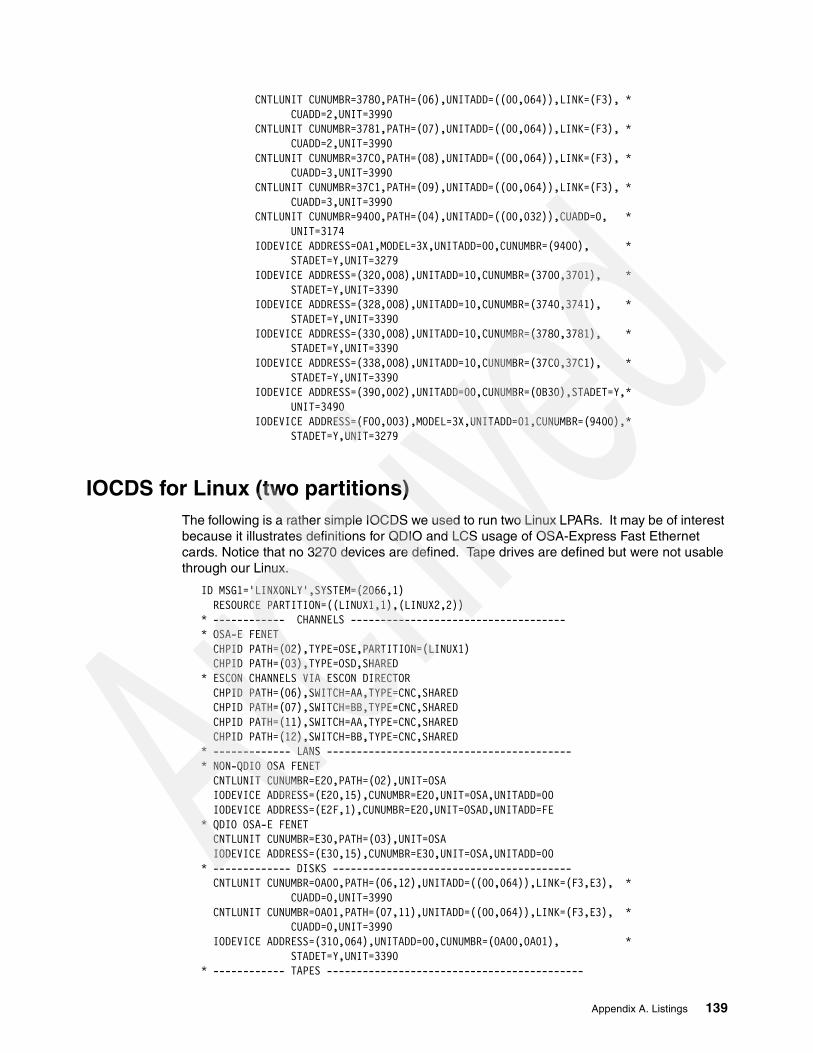
CNTLUNIT CUNUMBR=3780,PATH=(06),UNITADD=((00,064)),LINK=(F3), * CUADD=2,UNIT=3990 CNTLUNIT CUNUMBR=3781,PATH=(07),UNITADD=((00,064)),LINK=(F3), * CUADD=2,UNIT=3990 CNTLUNIT CUNUMBR=37C0,PATH=(08),UNITADD=((00,064)),LINK=(F3), * CUADD=3,UNIT=3990 CNTLUNIT CUNUMBR=37C1,PATH=(09),UNITADD=((00,064)),LINK=(F3), * CUADD=3,UNIT=3990 CNTLUNIT CUNUMBR=9400,PATH=(04),UNITADD=((00,032)),CUADD=0, * UNIT=3174 IODEVICE ADDRESS=0A1,MODEL=3X,UNITADD=00,CUNUMBR=(9400), * STADET=Y,UNIT=3279 IODEVICE ADDRESS=(320,008),UNITADD=10,CUNUMBR=(3700,3701), * STADET=Y,UNIT=3390 IODEVICE ADDRESS=(328,008),UNITADD=10,CUNUMBR=(3740,3741), * STADET=Y,UNIT=3390 IODEVICE ADDRESS=(330,008),UNITADD=10,CUNUMBR=(3780,3781), * STADET=Y,UNIT=3390 IODEVICE ADDRESS=(338,008),UNITADD=10,CUNUMBR=(37C0,37C1), * STADET=Y,UNIT=3390 IODEVICE ADDRESS=(390,002),UNITADD=00,CUNUMBR=(0B30),STADET=Y,* UNIT=3490 IODEVICE ADDRESS=(F00,003),MODEL=3X,UNITADD=01,CUNUMBR=(9400),* STADET=Y,UNIT=3279
IOCDS for Linux (two partitions)The following is a rather simple IOCDS we used to run two Linux LPARs. It may be of interest because it illustrates definitions for QDIO and LCS usage of OSA-Express Fast Ethernet cards. Notice that no 3270 devices are defined. Tape drives are defined but were not usable through our Linux.
ID MSG1='LINXONLY',SYSTEM=(2066,1) RESOURCE PARTITION=((LINUX1,1),(LINUX2,2)) * ------------ CHANNELS ------------------------------------ * OSA-E FENET CHPID PATH=(02),TYPE=OSE,PARTITION=(LINUX1) CHPID PATH=(03),TYPE=OSD,SHARED* ESCON CHANNELS VIA ESCON DIRECTOR CHPID PATH=(06),SWITCH=AA,TYPE=CNC,SHARED CHPID PATH=(07),SWITCH=BB,TYPE=CNC,SHARED CHPID PATH=(11),SWITCH=AA,TYPE=CNC,SHARED CHPID PATH=(12),SWITCH=BB,TYPE=CNC,SHARED * ------------- LANS ----------------------------------------- * NON-QDIO OSA FENET CNTLUNIT CUNUMBR=E20,PATH=(02),UNIT=OSA IODEVICE ADDRESS=(E20,15),CUNUMBR=E20,UNIT=OSA,UNITADD=00 IODEVICE ADDRESS=(E2F,1),CUNUMBR=E20,UNIT=OSAD,UNITADD=FE * QDIO OSA-E FENET CNTLUNIT CUNUMBR=E30,PATH=(03),UNIT=OSA IODEVICE ADDRESS=(E30,15),CUNUMBR=E30,UNIT=OSA,UNITADD=00 * ------------- DISKS ---------------------------------------- CNTLUNIT CUNUMBR=0A00,PATH=(06,12),UNITADD=((00,064)),LINK=(F3,E3), * CUADD=0,UNIT=3990 CNTLUNIT CUNUMBR=0A01,PATH=(07,11),UNITADD=((00,064)),LINK=(F3,E3), * CUADD=0,UNIT=3990 IODEVICE ADDRESS=(310,064),UNITADD=00,CUNUMBR=(0A00,0A01), * STADET=Y,UNIT=3390 * ------------ TAPES -------------------------------------------
Appendix A. Listings 139

CNTLUNIT CUNUMBR=0B00,PATH=(06,12),UNITADD=((00,016)),LINK=(D8,D8), * UNIT=3490 IODEVICE ADDRESS=(390,002),UNITADD=00,CUNUMBR=(0B00),STADET=Y, * UNIT=3490,PARTITION=(LINUX2)
IOCDS for z/OS, z/OS.e and Linux (LPARs)This last example is a rather large IOCDS that we used with seven LPARs. It includes HiperSockets and FICON CTC connections. Although we defined all four possible HiperSocket CHPIDs, we used only one of them (CHPID FC). We intended to loop our two FICON channels for a CTC connection, but our early z800 system did not have FICON CTC support competed, so we were unable to use it. Two IC channels are defined, to use with two Coupling Facility LPARs included in this definition.
We defined all our ESCON channels (and a number of non-existant switches) in this example, although we had nothing connected to CHPIDs 0A-13. This eliminated warning messages on the Support Element and HMC.
Part of this example must be considered non-standard. We defined disk addresses (IODEVICE statements) starting with unit addresses greater than zero. This is normally not recommended. We did it because other systems were sharing the same disk control units and, by restricting the range of unit addresses we included in our definitions, we reduced the risk of destroying disk volumes belonging to other systems.
ID MSG1='LPARTEST',SYSTEM=(2066,1) RESOURCE PARTITION=((ZOSE0001,1),(ADSYSTEM,2),(LINUX,3),(LINUX2,4), * (ZOSAD001,5),(ZOSAD002,6),(ZOSE0TWO,7), * (CFCC01,E),(CFCC02,F)) * ------------ CHANNELS ------------------------------------ * OSA-E GBE CHPID PATH=(00),TYPE=OSD,SHARED CHPID PATH=(01),TYPE=OSD,SHARED * OSA-E FENET CHPID PATH=(02),TYPE=OSE,PARTITION=(LINUX) CHPID PATH=(03),TYPE=OSD,SHARED * 1ST ESCON CARD CHPID PATH=(04),TYPE=CNC,SHARED CHPID PATH=(05),TYPE=CNC,SHARED CHPID PATH=(06),SWITCH=AA,TYPE=CNC,SHARED CHPID PATH=(07),SWITCH=AB,TYPE=CNC,SHARED CHPID PATH=(08),SWITCH=AC,TYPE=CNC,SHARED CHPID PATH=(09),SWITCH=AD,TYPE=CNC,SHARED CHPID PATH=(0A),SWITCH=0A,TYPE=CNC,SHARED CHPID PATH=(0B),SWITCH=0B,TYPE=CNC,SHARED * 2ND ESCON CARD CHPID PATH=(0C),TYPE=CNC,SHARED CHPID PATH=(0D),TYPE=CTC,SHARED CHPID PATH=(0E),SWITCH=0E,TYPE=CNC,SHARED CHPID PATH=(0F),SWITCH=0F,TYPE=CNC,SHARED CHPID PATH=(10),SWITCH=10,TYPE=CNC,SHARED CHPID PATH=(11),SWITCH=11,TYPE=CNC,SHARED CHPID PATH=(12),SWITCH=12,TYPE=CNC,SHARED CHPID PATH=(13),SWITCH=13,TYPE=CNC,SHARED * FICON EXPRESS CHPID PATH=(14),TYPE=FC,SHARED CHPID PATH=(15),TYPE=FC,SHARED * IC-3 CHPID PATH=(F0),TYPE=ICP,SHARED,NOTPART=(CFCC02),CPATH=(F1)
140 Technical Introduction: IBM zSeries 800

CHPID PATH=(F1),TYPE=ICP,SHARED,NOTPART=(CFCC01),CPATH=(F0) * HIPERSOCKETS CHPID PATH=(FC),TYPE=IQD,SHARED,OS=00 CHPID PATH=(FD),TYPE=IQD,SHARED,OS=00 CHPID PATH=(FE),TYPE=IQD,SHARED,OS=00 CHPID PATH=(FF),TYPE=IQD,SHARED,OS=00 * ------------- LANS ----------------------------------------- * NON-QDIO OSA CNTLUNIT CUNUMBR=E20,PATH=(02),UNIT=OSA IODEVICE ADDRESS=(E20,15),CUNUMBR=E20,UNIT=OSA,UNITADD=00 IODEVICE ADDRESS=(E2F,1),CUNUMBR=E20,UNIT=OSAD,UNITADD=FE * * QDIO OSA-E FENET CNTLUNIT CUNUMBR=E30,PATH=(03),UNIT=OSA IODEVICE ADDRESS=(E30,15),CUNUMBR=E30,UNIT=OSA,UNITADD=00 * * ------------- DISKS ---------------------------------------- CNTLUNIT CUNUMBR=3700,PATH=(06),UNITADD=((00,064)),LINK=(F3), * CUADD=0,UNIT=3990 CNTLUNIT CUNUMBR=3701,PATH=(07),UNITADD=((00,064)),LINK=(F3), * CUADD=0,UNIT=3990 IODEVICE ADDRESS=(0320,008),UNITADD=10,CUNUMBR=(3700,3701), * STADET=Y,UNIT=3390 * CNTLUNIT CUNUMBR=3740,PATH=(08),UNITADD=((00,064)),LINK=(F3), * CUADD=1,UNIT=3990 CNTLUNIT CUNUMBR=3741,PATH=(09),UNITADD=((00,064)),LINK=(F3), * CUADD=1,UNIT=3990 IODEVICE ADDRESS=(0328,008),UNITADD=10,CUNUMBR=(3740,3741), * STADET=Y,UNIT=3390 * CNTLUNIT CUNUMBR=3780,PATH=(06),UNITADD=((00,064)),LINK=(F3), * CUADD=2,UNIT=3990 CNTLUNIT CUNUMBR=3781,PATH=(07),UNITADD=((00,064)),LINK=(F3), * CUADD=2,UNIT=3990 IODEVICE ADDRESS=(0330,008),UNITADD=10,CUNUMBR=(3780,3781), * STADET=Y,UNIT=3390 * CNTLUNIT CUNUMBR=37C0,PATH=(08),UNITADD=((00,064)),LINK=(F3), * CUADD=3,UNIT=3990 CNTLUNIT CUNUMBR=37C1,PATH=(09),UNITADD=((00,064)),LINK=(F3), * CUADD=3,UNIT=3990 IODEVICE ADDRESS=(0338,008),UNITADD=10,CUNUMBR=(37C0,37C1), * STADET=Y,UNIT=3390 * * ------------ TAPES ------------------------------------------- CNTLUNIT CUNUMBR=0560,PATH=(05),UNITADD=((00,016)), * UNIT=3490 IODEVICE ADDRESS=(0560,016),UNITADD=00,CUNUMBR=(0560),STADET=Y, * UNIT=3490 * CNTLUNIT CUNUMBR=0B30,PATH=(06),UNITADD=((00,016)),LINK=(D8), * UNIT=3490 IODEVICE ADDRESS=(390,002),UNITADD=00,CUNUMBR=(0B30),STADET=Y, * UNIT=3490,PARTITION=(ZOSE0001) * ------------ 3270S ------------------------------------------- * FOR ZOSE0001 (LPAR #1; CUADD=0 FOR 2074) CNTLUNIT CUNUMBR=9400,PATH=(04),UNITADD=((00,032)),CUADD=0, * UNIT=3174 IODEVICE ADDRESS=0A1,MODEL=3X,UNITADD=00,CUNUMBR=(9400), *
Appendix A. Listings 141

STADET=Y,UNIT=3279,PARTITION=(ZOSE0001) IODEVICE ADDRESS=(F00,003),MODEL=3X,UNITADD=01,CUNUMBR=(9400), * STADET=Y,UNIT=3279,PARTITION=(ZOSE0001) * * FOR ADSYSTEM (LPAR #2; CUADD=1 FOR 2074) CNTLUNIT CUNUMBR=9401,PATH=(04),UNITADD=((00,008)),CUADD=1, * UNIT=3174 IODEVICE ADDRESS=(700,008),MODEL=X,UNITADD=00,CUNUMBR=(9401), * STADET=Y,UNIT=3279,PARTITION=(ADSYSTEM) * * FOR ZOSAD001 (LPAR #5; CUADD=5 FOR 2074) CNTLUNIT CUNUMBR=9405,PATH=(04),UNITADD=((00,008)),CUADD=5, * UNIT=3174 IODEVICE ADDRESS=(700,008),MODEL=X,UNITADD=00,CUNUMBR=(9405), * STADET=Y,UNIT=3279,PARTITION=(ZOSAD001) * * FOR ZOSAD002 (LPAR #6; CUADD=6 FOR 2074) CNTLUNIT CUNUMBR=9406,PATH=(04),UNITADD=((00,008)),CUADD=6, * UNIT=3174 IODEVICE ADDRESS=(700,008),MODEL=X,UNITADD=00,CUNUMBR=(9406), * STADET=Y,UNIT=3279,PARTITION=(ZOSAD002) * * FOR ZOSE0TWO (LPAR #7; CUADD=7 FOR 2074) CNTLUNIT CUNUMBR=9407,PATH=(04),UNITADD=((00,008)),CUADD=7, * UNIT=3174 IODEVICE ADDRESS=(700,008),MODEL=X,UNITADD=00,CUNUMBR=(9407), * STADET=Y,UNIT=3279,PARTITION=(ZOSE0TWO) * * ------------ ESCON CTCS --------------------------------------- CNTLUNIT CUNUMBR=C100,PATH=(0C),UNITADD=((00,008)),CUADD=1, * UNIT=SCTC IODEVICE ADDRESS=(C100,008),UNITADD=00,CUNUMBR=(C100), * UNIT=SCTC,NOTPART=(ZOSE0001) CNTLUNIT CUNUMBR=C200,PATH=(0C),UNITADD=((00,008)),CUADD=2, * UNIT=SCTC IODEVICE ADDRESS=(C200,008),UNITADD=00,CUNUMBR=(C200), * UNIT=SCTC,NOTPART=(ADSYSTEM) CNTLUNIT CUNUMBR=C300,PATH=(0C),UNITADD=((00,008)),CUADD=3, * UNIT=SCTC IODEVICE ADDRESS=(C300,008),UNITADD=00,CUNUMBR=(C300), * UNIT=SCTC,NOTPART=(LINUX) CNTLUNIT CUNUMBR=C400,PATH=(0C),UNITADD=((00,008)),CUADD=4, * UNIT=SCTC IODEVICE ADDRESS=(C400,008),UNITADD=00,CUNUMBR=(C400), * UNIT=SCTC,NOTPART=(LINUX2) CNTLUNIT CUNUMBR=C500,PATH=(0C),UNITADD=((00,008)),CUADD=5, * UNIT=SCTC IODEVICE ADDRESS=(C500,008),UNITADD=00,CUNUMBR=(C500), * UNIT=SCTC,NOTPART=(ZOSAD001) CNTLUNIT CUNUMBR=C600,PATH=(0C),UNITADD=((00,008)),CUADD=6, * UNIT=SCTC IODEVICE ADDRESS=(C600,008),UNITADD=00,CUNUMBR=(C600), * UNIT=SCTC,NOTPART=(ZOSAD002) CNTLUNIT CUNUMBR=C700,PATH=(0C),UNITADD=((00,008)),CUADD=7, * UNIT=SCTC IODEVICE ADDRESS=(C700,008),UNITADD=00,CUNUMBR=(C700), * UNIT=SCTC,NOTPART=(ZOSE0TWO) * CNTLUNIT CUNUMBR=D100,PATH=(0D),UNITADD=((00,008)),CUADD=1, * UNIT=SCTC
142 Technical Introduction: IBM zSeries 800
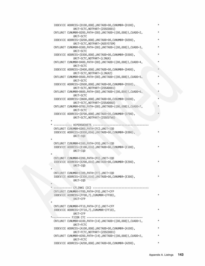
IODEVICE ADDRESS=(D100,008),UNITADD=00,CUNUMBR=(D100), * UNIT=SCTC,NOTPART=(ZOSE0001) CNTLUNIT CUNUMBR=D200,PATH=(0D),UNITADD=((00,008)),CUADD=2, * UNIT=SCTC IODEVICE ADDRESS=(D200,008),UNITADD=00,CUNUMBR=(D200), * UNIT=SCTC,NOTPART=(ADSYSTEM) CNTLUNIT CUNUMBR=D300,PATH=(0D),UNITADD=((00,008)),CUADD=3, * UNIT=SCTC IODEVICE ADDRESS=(D300,008),UNITADD=00,CUNUMBR=(D300), * UNIT=SCTC,NOTPART=(LINUX) CNTLUNIT CUNUMBR=D400,PATH=(0D),UNITADD=((00,008)),CUADD=4, * UNIT=SCTC IODEVICE ADDRESS=(D400,008),UNITADD=00,CUNUMBR=(D400), * UNIT=SCTC,NOTPART=(LINUX2) CNTLUNIT CUNUMBR=D500,PATH=(0D),UNITADD=((00,008)),CUADD=5, * UNIT=SCTC IODEVICE ADDRESS=(D500,008),UNITADD=00,CUNUMBR=(D500), * UNIT=SCTC,NOTPART=(ZOSAD001) CNTLUNIT CUNUMBR=D600,PATH=(0D),UNITADD=((00,008)),CUADD=6, * UNIT=SCTC IODEVICE ADDRESS=(D600,008),UNITADD=00,CUNUMBR=(D600), * UNIT=SCTC,NOTPART=(ZOSAD002) CNTLUNIT CUNUMBR=D700,PATH=(0D),UNITADD=((00,008)),CUADD=7, * UNIT=SCTC IODEVICE ADDRESS=(D700,008),UNITADD=00,CUNUMBR=(D700), * UNIT=SCTC,NOTPART=(ZOSE0TWO) * * ------------ HIPERSOCKETS ------------------------------------- CNTLUNIT CUNUMBR=E000,PATH=(FC),UNIT=IQD IODEVICE ADDRESS=(E000,016),UNITADD=00,CUNUMBR=(E000), * UNIT=IQD * CNTLUNIT CUNUMBR=E100,PATH=(FD),UNIT=IQD IODEVICE ADDRESS=(E100,016),UNITADD=00,CUNUMBR=(E100), * UNIT=IQD * CNTLUNIT CUNUMBR=E200,PATH=(FE),UNIT=IQD IODEVICE ADDRESS=(E200,016),UNITADD=00,CUNUMBR=(E200), * UNIT=IQD * CNTLUNIT CUNUMBR=E300,PATH=(FF),UNIT=IQD IODEVICE ADDRESS=(E300,016),UNITADD=00,CUNUMBR=(E300), * UNIT=IQD * * ------------ CFLINKS (IC) ------------------------------------- CNTLUNIT CUNUMBR=FF00,PATH=(F0),UNIT=CFP IODEVICE ADDRESS=(FF00,7),CUNUMBR=(FF00), * UNIT=CFP * CNTLUNIT CUNUMBR=FF10,PATH=(F1),UNIT=CFP IODEVICE ADDRESS=(FF10,7),CUNUMBR=(FF10), * UNIT=CFP *------------ FICON CTC ------------------------------------- CNTLUNIT CUNUMBR=A100,PATH=(14),UNITADD=((00,008)),CUADD=1, * UNIT=FCTC IODEVICE ADDRESS=(A100,008),UNITADD=00,CUNUMBR=(A100), * UNIT=FCTC,NOTPART=(ZOSE0001) CNTLUNIT CUNUMBR=A200,PATH=(14),UNITADD=((00,008)),CUADD=2, * UNIT=FCTC IODEVICE ADDRESS=(A200,008),UNITADD=00,CUNUMBR=(A200), *
Appendix A. Listings 143

UNIT=FCTC,NOTPART=(ADSYSTEM) CNTLUNIT CUNUMBR=A300,PATH=(14),UNITADD=((00,008)),CUADD=3, * UNIT=FCTC IODEVICE ADDRESS=(A300,008),UNITADD=00,CUNUMBR=(A300), * UNIT=FCTC,NOTPART=(LINUX) CNTLUNIT CUNUMBR=A400,PATH=(14),UNITADD=((00,008)),CUADD=4, * UNIT=FCTC IODEVICE ADDRESS=(A400,008),UNITADD=00,CUNUMBR=(A400), * UNIT=FCTC,NOTPART=(LINUX2) CNTLUNIT CUNUMBR=A500,PATH=(14),UNITADD=((00,008)),CUADD=5, * UNIT=FCTC IODEVICE ADDRESS=(A500,008),UNITADD=00,CUNUMBR=(A500), * UNIT=FCTC,NOTPART=(ZOSAD001) CNTLUNIT CUNUMBR=A600,PATH=(14),UNITADD=((00,008)),CUADD=6, * UNIT=FCTC IODEVICE ADDRESS=(A600,008),UNITADD=00,CUNUMBR=(A600), * UNIT=FCTC,NOTPART=(ZOSAD002) CNTLUNIT CUNUMBR=A700,PATH=(14),UNITADD=((00,008)),CUADD=7, * UNIT=FCTC IODEVICE ADDRESS=(A700,008),UNITADD=00,CUNUMBR=(A700), * UNIT=FCTC,NOTPART=(ZOSE0TWO) * CNTLUNIT CUNUMBR=B100,PATH=(15),UNITADD=((00,008)),CUADD=1, * UNIT=FCTC IODEVICE ADDRESS=(B100,008),UNITADD=00,CUNUMBR=(B100), * UNIT=FCTC,NOTPART=(ZOSE0001) CNTLUNIT CUNUMBR=B200,PATH=(15),UNITADD=((00,008)),CUADD=2, * UNIT=FCTC IODEVICE ADDRESS=(B200,008),UNITADD=00,CUNUMBR=(B200), * UNIT=FCTC,NOTPART=(ADSYSTEM) CNTLUNIT CUNUMBR=B300,PATH=(15),UNITADD=((00,008)),CUADD=3, * UNIT=FCTC IODEVICE ADDRESS=(B300,008),UNITADD=00,CUNUMBR=(B300), * UNIT=FCTC,NOTPART=(LINUX) CNTLUNIT CUNUMBR=B400,PATH=(15),UNITADD=((00,008)),CUADD=4, * UNIT=FCTC IODEVICE ADDRESS=(B400,008),UNITADD=00,CUNUMBR=(B400), * UNIT=FCTC,NOTPART=(LINUX2) CNTLUNIT CUNUMBR=B500,PATH=(15),UNITADD=((00,008)),CUADD=5, * UNIT=FCTC IODEVICE ADDRESS=(B500,008),UNITADD=00,CUNUMBR=(B500), * UNIT=FCTC,NOTPART=(ZOSAD001) CNTLUNIT CUNUMBR=B600,PATH=(15),UNITADD=((00,008)),CUADD=6, * UNIT=FCTC IODEVICE ADDRESS=(B600,008),UNITADD=00,CUNUMBR=(B600), * UNIT=FCTC,NOTPART=(ZOSAD002) CNTLUNIT CUNUMBR=B700,PATH=(15),UNITADD=((00,008)),CUADD=7, * UNIT=FCTC IODEVICE ADDRESS=(B700,008),UNITADD=00,CUNUMBR=(B700), * UNIT=FCTC,NOTPART=(ZOSE0TWO)
144 Technical Introduction: IBM zSeries 800

Appendix B. Preliminary performance
At the time of writing, only preliminary performance information was available and key portions are included here.
It is important to understand the provenance of these measurements. They come from the same measurements that produce IBM’s LSPR information. (The name comes from Large Systems Performance Report, but “LSPR” is typically used as a proper name.) These are based on a number of standard workloads that have been run on many IBM S/390 machines for years and are felt to reasonably represent their workloads. There are workloads for batch, for TSO, for CICS and DB2, for IMS, and so forth. We assume IBM will eventually publish the normal LSPR information for the z/800 after all the workloads have been run and the results analyzed. We had only a small amount of preliminary information, which is presented below.
LSPR measurements are intended to measure only the processor performance of a system. They are run in an environment with excess memory and extensive I/O connectivity, in an effort to make processor performance the limiting factor. This may not represent your environment, and you must factor this difference into your use of LSPR numbers (including the material present here).
Also, in order to keep the workload uniform over many generations of S/390 machines, the jobs involved do not utilize some of the newer system functions. For example, FICON channels are not used, no 64-bit exploitation is used, and the newer cryptographic processors are not used. Using this newer technology may offer performance benefits that are not reflected in the LSPR numbers.
Compared to an IBM 9672 generation 4 server, the z/800 performance was as follows:
2066-0A1 1.1 - 1.4 times the performance of a 9672-R15 (1-way)2066-0B1 1.6 - 2.0 times the performance of a 9672-R15 (1-way)2066-0C1 1.7 - 2.4 times the performance of a 9672-R15 (1-way)2066-0A2 1.9 - 2.4 times the performance of a 9672-R25 (2-way)2066-0A2 1.3 - 1.7 times the performance of a 9672-R35 (3-way)
Compared to an IBM 9672 generation 5 server, the z/800 performance was:
2066-0A1 0.9 - 1.0 times the performance of a 9672-RA62066-0B1 1.2 - 1.4 times the performance of a 9672-RA6 2066-0C1 1.1 - 1.3 times the performance of a 9672-R16 (1-way)
B
© Copyright IBM Corp. 2002 145

2066-001 1.4 - 1.7 times the performance of a 9672-R16 (1-way)2066-0A2 1.0 - 1.3 times the performance of a 9672-R26 (2-way)2066-002 1.0 - 1.2 times the performance of a 9672-R36 (3-way)2066-003 1.1 - 1.3 times the performance of a 9672-R46 (4-way)2066-004 1.1 - 1.3 times the performance of a 9672-R56 (5-way)
Compared to an IBM Multiprise 3000, the z/800 performance was:
2066-0A1 1.2 - 1.5 times the performance of a 7060-H30 (1-way)2066-0B1 0.9 - 1.1 times the performance of a 7060-H50 (1-way)2066-0A2 1.1 - 1.3 times the performance of a 7060-H70 (2-way)
These Internal Throughput Rate Ratios (ITRRs) were obtained using OS/390 V2R10. The usual disclaimers apply to these numbers. More detailed information, including breakouts by types of workloads, should be available sometime after the first shipments of the z/800s.
It is important to note that these numbers are based on LSPR workloads that represent traditional S/390 work. New workloads (based on C, C++, Java, WebSphere, and so forth) may have different performance profiles and ratios. Early measurements have shown a 2066-001 to have up to 25% more SAP throughput, up to 25% more Lotus Notes users, or 25% more web-base transactions than a G5 9672-T16 system.
146 Technical Introduction: IBM zSeries 800

Special notices
References in this publication to IBM products, programs or services do not imply that IBM intends to make these available in all countries in which IBM operates. Any reference to an IBM product, program, or service is not intended to state or imply that only IBM's product, program, or service may be used. Any functionally equivalent program that does not infringe any of IBM's intellectual property rights may be used instead of the IBM product, program or service.
Information in this book was developed in conjunction with use of the equipment specified, and is limited in application to those specific hardware and software products and levels.
IBM may have patents or pending patent applications covering subject matter in this document. The furnishing of this document does not give you any license to these patents. You can send license inquiries, in writing, to the IBM Director of Licensing, IBM Corporation, North Castle Drive, Armonk, NY 10504-1785.
Licensees of this program who wish to have information about it for the purpose of enabling: (i) the exchange of information between independently created programs and other programs (including this one) and (ii) the mutual use of the information which has been exchanged, should contact IBM Corporation, Dept. 600A, Mail Drop 1329, Somers, NY 10589 USA.
Such information may be available, subject to appropriate terms and conditions, including in some cases, payment of a fee.
The information contained in this document has not been submitted to any formal IBM test and is distributed AS IS. The use of this information or the implementation of any of these techniques is a customer responsibility and depends on the customer's ability to evaluate and integrate them into the customer's operational environment. While each item may have been reviewed by IBM for accuracy in a specific situation, there is no guarantee that the same or similar results will be obtained elsewhere. Customers attempting to adapt these techniques to their own environments do so at their own risk.
Any pointers in this publication to external Web sites are provided for convenience only and do not in any manner serve as an endorsement of these Web sites.
The following terms are trademarks of other companies:
C-bus is a trademark of Corollary, Inc. in the United States and/or other countries.
Java and all Java-based trademarks and logos are trademarks or registered trademarks of Sun Microsystems, Inc. in the United States and/or other countries.
Microsoft, Windows, Windows NT, and the Windows logo are trademarks of Microsoft Corporation in the United States and/or other countries.
PC Direct is a trademark of Ziff Communications Company in the United States and/or other countries and is used by IBM Corporation under license.
ActionMedia, LANDesk, MMX, Pentium and ProShare are trademarks of Intel Corporation in the United States and/or other countries.
UNIX is a registered trademark in the United States and other countries licensed exclusively
© Copyright IBM Corp. 2002 147
through The Open Group.
SET, SET Secure Electronic Transaction, and the SET Logo are trademarks owned by SET Secure Electronic Transaction LLC.
Other company, product, and service names may be trademarks or service marks of others.
148 Technical Introduction: IBM zSeries 800
Related publications
The publications listed in this section are considered particularly suitable for a more detailed discussion of the topics covered in this redbook.
IBM RedbooksFor information on ordering these publications, see “How to get IBM Redbooks” on page 149.
� OSA-Express Implementation Guide, SG24-5948
� IBM e(logo) Server zSeries 900 Technical Guide, SG24-5975
� Introducing the IBM 2074 Control Unit, SG24-5966
� FICON Native Implementation and Reference Guide, SG24-6266
� zSeries HiperSockets, Redpaper, REDP0160
� z/OS Intelligent Resource Director, SG24-5952
Other resourcesThese publications are also relevant as further information sources:
� z/OS.e Overview, GA22-7869
� z/OS and z/OS.e Planning for Installation, GA22-7504
� z/OS.e Licensed Program Specifications, GA22-7868
� ServerPac: Using the Installation Dialog, SA22-7815-03
� z/OS MVS Planning: Workload Management, SA22-7602
Referenced Web sitesThese Web sites are also relevant as further information sources:
� Resource Link
http://www.ibm.com/servers/resourcelink
How to get IBM RedbooksSearch for additional Redbooks or Redpieces, view, download, or order hardcopy from the Redbooks Web site:
ibm.com/redbooks
Also download additional materials (code samples or diskette/CD-ROM images) from this Redbooks site.
Redpieces are Redbooks in progress; not all Redbooks become Redpieces and sometimes just a few chapters will be published this way. The intent is to get the information out much quicker than the formal publishing process allows.
© Copyright IBM Corp. 2002 149

IBM Redbooks collectionsRedbooks are also available on CD-ROMs. Click the CD-ROMs button on the Redbooks Web site for information about all the CD-ROMs offered, as well as updates and formats.
150 Technical Introduction: IBM zSeries 800

Index
Numerics155 ATM 602066-0FL 1302074 unit 1333174s and 2074s 13332-bit and 31-bit operation 13432-bit and 64-bit Linux 414mm tape drive 12964-bit capabilities, operating systems 2764-bit support 37
AACTIVATE icon 69AES 36AMDs 15ASCII 129ASCII or EBCDIC 131Asynchronous Data Mover facility 4Asynchronous Transfer Mode 60ATM (155 Mbps) 18
BBase Processor Unit - Package 11basic mode 135battery feature (IBF) 3big endian 129blocking chpid addresses 24book 17BPU Box 15BPU-PK 11, 13bus and tag 49Byte multiplexor 50
Ccable ordering 81cable ordering process 3cables for the z800 131cables, replacement 84cache discussion 107Cage Controller 19cage for I/O cards 2Capacity Backup (CBU) 104Capacity Upgrade on Demand (CUoD) 104card Indicators 57card indicators 53, 58, 59, 60cards 17Cargo I/O cage 132CBU Feature information 106CBU test sessions 105Certificate Authority 36CF links 110CF structure duplexing 110
© Copyright IBM Corp. 2002
channel cables 132Channel definitions in IOCP 66Channel Subsystem Priority Queuing 118CHPID mapping 24CHPID Mapping Tool 85, 87CHPID, IOCDS 66CICS connector 32CNTLUNIT, IOCDS 66Common Cryptographic Architecture (CCA) 91Compatibility 2Compatibility I/O Cage 3Compatibility I/O cages 132Concurrent upgrades 23coupled environment 30Coupling Facility 22Coupling Facility channel 16Coupling Facility channels (ICB-3s) 11CRYPTO overview 88Crypto PCI (PCICA) cards 18Crypto PCI (PCICC) cards 18Cryptographic Coprocessor Facility CCF 89cryptographic coprocessors 3, 130cryptographic hardware elements 88Cryptographic performance 93cryptographic processors, programming 133CUoD and CBU 104Customized Offerings Driver (COD) 34
Ddata compression, hardware 125Desktop on Call (DTOC) 99DEVMAP on the z800 127Differences, z/900 and Multiprise 3000 3DIMM cards 14divided box 29domain 16driver levels 134dual processors 10Dyadic Processor 22Dynamic CF dispatching 109Dynamic Channel Path management 117Dynamic I/O configuration 109Dynamic ICF expansion 110
EEBCDIC 131EBCDIC and ASCII 129EFS machines 4Emergency Power Off 130emulated I/O 3emulated I/O LAN interfaces 132Emulated I/O to OSA migration 61endian, big 129engine-based (PU) pricing 31
151

ES conversion channels 51ESCON cables 51ESCON cards 19ESCON channels 2, 17, 50ESCON CTC 54ESCON Directors 24Ethernet hub 81Ethernet wiring 134ETR connection 93
FFast Ethernet 18, 57fast Ethernet card 57FDDI adapters 3feature code 0074 101feature code 0086 101feature code 0087 101feature code 0088 101feature code 0089 101feature code 0219 111feature code 0227 82feature code 0861 88, 90feature code 0862 88feature code 0865 88feature code 1208 14feature code 2319 52feature code 2320 52feature code 2323 50feature code 2324 50feature code 2362 60feature code 2363 60feature code 2364 58feature code 2365 58feature code 2366 57feature code 2367 59feature code 2904 102feature code 2941 102feature code 3700 71feature code 3702 109feature code 6092 101feature code 6093 101feature codes 3601, 3602, 3603, and 3504 109feature codes 3605, 3606, 3607, and 3608 5Fibre cables and connectors 83Fibre Optic SubAssembly (FOSA) 84FICON cards 18FICON CTC 54FICON Express 51, 52FQC direct-attach Harness 82
GGeographically Dispersed Parallel Sysplex 107Gigabit Ethernet 18, 58
HHardware Management Console (HMC) 3, 99Hardware Storage Area 129High speed token ring 18
HiperSockets 19, 47, 67, 77HiperSockets and VM 38HiperSockets in IOCP 78HiperSockets in z/OS TCP/IP profile 79Hipersockets, price 134HMC 15, 16, 24, 81HMC connectivity 100HMC levels 103HMC, existing 103
II/O cage 15, 16, 130I/O Summary 18IBM 2074 50, 69IBM 3174 control units 49IBM 34xx tape drives 49IBM 4755 Cryptographic Adatper card 89IBM 9034 132IBM 9034 (Pacer) 49IBM 9037 Sysplex Time 93IBM INRANGE FC/9000-128 Fibre Channel Director mod-el 001 51IBM INRANGE FC/9000-128 Fibre Channel Director mod-el 128 51IBM McDATA ED-6064 Enterprise Fibre Channel Director 51ICB-2 connections 3ICB-3 channels 19ICB-3 connections 11ICF functions 2ICMF function 4ICSF 36ICSF functions 133IFL 71, 73IFL functions 2IFL, difference 130IFL, with VM 40IMAGE profiles 75Integrated Coupling Facility (ICF) 10integrated disks 127Integrated Facility for Linux 71Integrated Linux Facility (IFL) 10Intelligent Resource Director 114internal CF channels 19Internal coupling channels 113internal disk drives 3Internal Throughput Rate Ratios 146Intersystem coupling channels 18IOCDS 24, 64IOCDS listings 137IOCP definitions 64IOCP source file 75IOCP source input file 67IODEVICE, IOCDS 66IODF 137IOP Box 15ISC-3 channels 19ISV application 128
152 Technical Introduction: IBM zSeries 800

Kkeys, master 133
LL1 cache 11L2 cache 11LAN cards 18LCS mode 43LICENSE system parameter 28Linux 40Linux CD-ROM 131Linux distributions 42Linux installation 43Linux Offering 131Linux offering 5Linux-Only Processor 22Linux-only system 135LPAR CPU management 116LPAR name ZOSExxxx 28LPAR names 66LPAR setup and examples 74LSPR information 145LX (long wavelength) 84
MMachine Information 87maintenance charges 135master keys 133MBA 16MCL updates 61MCM 12, 16Memory 2memory bus adapter (MBA) 11memory DIMMs 13memory sizes 11middleware pricing rules 33Mode Conditioning Patch (MCP) cables 84Model upgrades 22modem 81MSU capacity 29m-sys for operation and setup 37MT-RJ connector 94MT-RJ connectors 51multiple chip module (MCM) 12Multiple Image Facility (MIF) 67
Nnoise level 81non disruptive upgrade 127non-z/OS partitions, IRD 119
OOffering for Linux 5office environment 127Open FCP 107Optica 49Optica converters 132
Optica Technologies, Incorporated 94OSA adapters 24OSA Express Fast Ethernet 43OSA/SF program 57, 61OSA-2 adapters 3OSA-Express adapters 56OSC/ETR cards 15
PPacer 50, 132Pacer units 49Parallel channel planning 49parallel channels 3Parallel Sysplex 2part number 11P0360 129Passat I/O cage 132PCICA cards 92PCICC cards 90, 133Peer mode 111performance information 145performance scale 4Physical planning 80PIN 36portname parameter 43Power design 20power factor 80power feeds 2power plugs 80Power Save function 3power supplies 20power switch 130power, single phase 80processor cage 15Processor cycle speed 23Processor data flow 11Processors 2, 10push-button MCL 62
QQDIO 59QDIO mode 43, 57, 59, 60QDIO programming 77Quad Processor 22
Rraised-floor environment 2Redbooks Web site 149
Contact us ixrefrigeration 3Repair&Verify 50, 129RESET and IMAGE profiles 75RESET profile 76Resource Link 85RESOURCE, IOCDS 66RMF (Resource Measurement Facility) 92routers 56RPQ 8P1767 50RSA 36
Index 153

SS/370 mode 128SAN infrastructure 52SAP processor 129SAPs 23SCSI connections 129SE and HMC connectivity 100self-timed interfaces (STIs) 11ServerPac, z/OS.e 28service for z/OS.e 128share disks 128, 131shared DASD 128slots in the I/O cage 17Software summary 6spare ESCON port 129spare processor 3Spare PUs 10, 114SSI interface 20SSL 93SSL (Secure Sockets Layer) 92SSL processing 133starter system 34STEPLIB 128sub-capacity pricing 30Sub-Capacity Reporting Tool (SCRT) 32Sub-Dyadic Processor 22Sub-Uniprocessor 22Support Element 14, 80Support Element (SE) 98Support Elements 15SX (short wavelength) 84Sysplex clock 3Sysplex Timer 16System Administration Facility 39System Assist Processor (SAP) 2System Assistance Processor (SAP) 10System control 19system frame 15System-managed CF structure duplexing 110
TTCP/IP 59TKE hardware 133token ring 18, 59tool kit 81tools 130Triadic Processor 22Triple DES 36Trusted Key Entry TKE 89TSO users, z/OS.e 28
UUni-processor 22Unix system services 36upgrade from a Linux 0LF 127User Defined Extensions UDX 91
VVIF 39VM cryptographic support 40VM releases 38VM with an IFL engine 131VPD diskettes 130VSAM 37VSE/ESA 135
WWeb interfaces, HMC/SE 134WLM LPAR Weight Management 116WLM support 37WLM Vary CPU Management 117
YYaST 46
Zz/800 models 21z/OS 1.3, new functions 36z/OS and OS/390 36z/OS.e 6, 28, 128z/OS.e and 2074 134z/OS.e in an IFL 131z/OS.e pricing model 29z/OS.e specific limitations 28z/VM Subscription and Support 6z/VM version 4 6zFS performance 37ZOSExxxx (LPAR name) 28
154 Technical Introduction: IBM zSeries 800

(0.2”spine)0.17”<->
0.473”90<->
249 pages
Technical Introduction: IBM
zSeries 800


®
SG24-6515-00 ISBN 073842417X
INTERNATIONAL TECHNICALSUPPORTORGANIZATION
BUILDING TECHNICAL INFORMATION BASED ON PRACTICAL EXPERIENCE
IBM Redbooks are developed by the IBM International Technical Support Organization. Experts from IBM, Customers and Partners from around the world create timely technical information based on realistic scenarios. Specific recommendations are provided to help you implement IT solutions more effectively in your environment.
For more information:ibm.com/redbooks
Technical Introduction:IBM zSeries 800
Software: z/OS, z/OS.e, Linux
Planning and installation
Overview and FAQs
This IBM Redbook describes the IBM z800 family of systems. These are IBM machine type 2066 systems, with a number of different models. The z800 systems are smaller but quite similar to the well accepted z900 systems, often known by their development name as the “Freeway” series. Consequently, the z800 machines are sometimes characterized as “baby Freeways.” This is close, but not quite accurate. The z800 machines offer a lower entry point, in both price and performance, than the z900s, but have a few characteristics that differ from the larger systems.
z/OS.e is a special packaging of z/OS that is unique to the z800 machines. It is a reduced function z/OS with a significantly lower price than full z/OS. z/OS.e is targeted at new workloads based on e-business constructs, using C, C++, and Java languages and working with WebSphere, DB2, and similar middleware. Traditional workloads cannot be run with z/OS.e.
This book is for readers with a general S/390 and z/OS background; common terms and acronyms are used without introduction. Also included is a limited amount of introductory material for Linux users who are not familiar with S/390 platforms. The goal of the book is to provide a technical introduction to the z800.
Back cover