front fan and fan holder installationh10032. fan and fan holder installation introduction this...
TRANSCRIPT

Front fan and fan holder installation
IntroductionThis document describes how to install a front fan and fan holder/card guide in an HP computer.
Kit contents● Fan
● Combination card guide/fan holder for the HP Z200, Z210, or Z400 computer
● Warranty information
Your responsibilitiesYou are responsible for determining whether the product is appropriate for your use and will interfacewith other equipment without malfunction or damage. You are also responsible for backing up databefore installing any product and for regularly backing up data after installing the product. HP is notliable for any damage to equipment or data loss resulting from the use of any product. To determine thecompatibility of this product with your computer or workstation, view QuickSpecs athttp://www.hp.com/go/productbulletin.
Before you beginNOTE: Only computers having non-factory-integrated, high-power PCI cards require the additionalcooling provided by the optional front chassis fan included in this kit. This front fan is not recommendedfor use on computers that have hard drives mounted in the optical bays if your environmentaltemperature exceeds 27°C (80°F). This might reduce long-term reliability of these hard drives.
© 2011 Hewlett-Packard Development Company, L.P. Printed in the U.S.
ENWW Introduction 1

Warnings and cautionsWARNING! Any surface or area of the equipment marked with this symbol indicates thepresence of a hot surface or hot component. If this surface is contacted, the potential for injury exists.To reduce the risk of injury from a hot component, enable the surface to cool before touching.
WARNING! Any surface or area of the equipment marked with this symbol indicates thepresence of an electrical shock hazard. To reduce the risk of injury from electrical shock, do not openany enclosed area marked with this symbol.
WARNING! To reduce the risk of electric shock or damage to your equipment:
— Do not disable the power cord grounding plug. The grounding plug is an important safety feature.
— Plug the power cord in a grounded (earthed) outlet that is easily accessible at all times.
— Disconnect power from the equipment by unplugging the power cord from the electrical outlet.
WARNING! To reduce the risk of serious injury, read the Safety & Comfort Guide. It describesproper computer setup, posture, health, and work habits for computer users, and provides importantelectrical and mechanical safety information. This guide is located at http://www.hp.com/ergo and onthe documentation CD (if one is included with the product).
WARNING! If a product is shipped in packaging marked with this symbol, , the product must
always be lifted by two persons to avoid personal injury due to product weight.
CAUTION: Static electricity can damage the electronic components of the computer. Beforebeginning these procedures, be sure you discharge static electricity by briefly touching a groundedmetal object.
CAUTION: To prevent damage to the computer, observe the following Electrostatic Discharge (ESD)precautions while performing the system parts removal and replacement procedures:
— Work on a static-free mat.
— Wear a static strap to ensure that any accumulated electrostatic charge is discharged from yourbody to the ground.
— Create a common ground for the equipment you are working on by connecting the static-free mat,static strap, and peripheral units to that piece of equipment.
NOTE: HP accessories are for use in HP computer products. They have been extensively tested forreliability and are manufactured to high quality standards.
2 Front fan and fan holder installation ENWW

Step 1—Preparing for component installationNOTE: Computer models vary. All illustrations are examples only.
Accessing the internal components of the computer
1. If you need help preparing the computer for this installation, consult the removal and replacementprocedures in the service guide for your computer at http://www.hp.com/support/manuals.
2. Power down the computer, and then disconnect the power cord.
3. Power down all external devices, and then disconnect them from the computer.
4. Remove the side access panel.
Step 2—Installing the front fan and fan holder
1. To have adequate clearance for installing the fan, remove any full-length expansion cards:
a. (Z400 only) If installed, remove the expansion card support by removing the two connectingscrews (1) and lifting up on the support (2).
Figure 1 Removing expansion card support (Z400)
ENWW Step 1—Preparing for component installation 3

b. If installed, remove the card hold-down clamp: grasp the top of the clamp (1), squeeze therelease handles until the bottom of the clamp releases from the clamp rail (2) (it should clickwhen it releases), and swing the clamp out from the back panel (3).
Figure 2 Removing expansion card hold-down clamp (Z200 and Z210)
c. Disconnect the 1394 power cable if it is used by any of the full-length expansion cards.
4 Front fan and fan holder installation ENWW
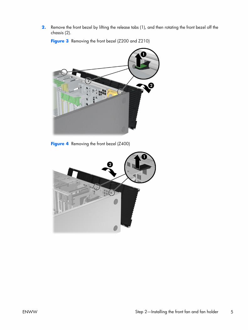
2. Remove the front bezel by lifting the release tabs (1), and then rotating the front bezel off thechassis (2).
Figure 3 Removing the front bezel (Z200 and Z210)
Figure 4 Removing the front bezel (Z400)
ENWW Step 2—Installing the front fan and fan holder 5

3. (Z400 with hood sensor only) Remove the hood sensor and mounting bracket:
a. Disconnect the sensor power cable from the system board (1).
Figure 5 Removing the hood sensor and mounting bracket (Z400)
b. Slide the hood sensor out of its mounting bracket (2).
c. Remove the hood sensor mounting bracket by using a Torx screwdriver to remove the twoscrews that hold the hood sensor bracket to the chassis (3).
4. Insert the fan unit into the fan holder/card guide. Align the fan with the label facing inward. If anairflow indicator is present on the fan, make sure it points toward the holder and the rear of thechassis. Position the power cable so that it has the maximum length to reach the system board.
Figure 6 Inserting the fan into the fan holder/card guide
6 Front fan and fan holder installation ENWW
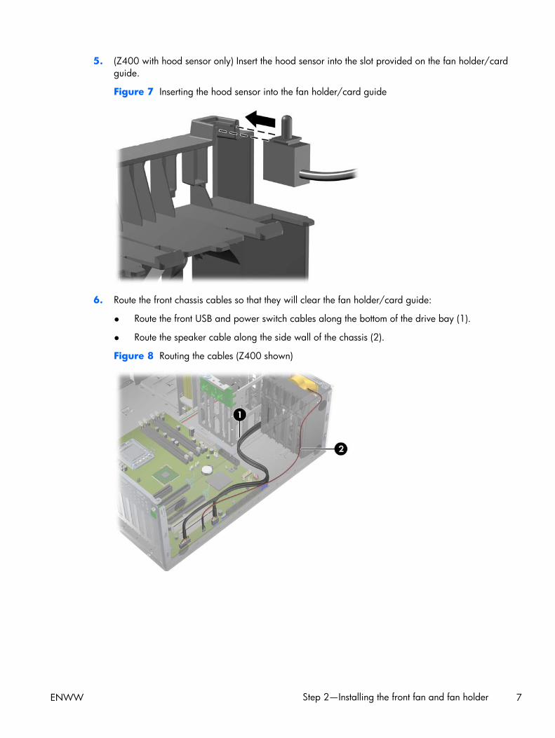
5. (Z400 with hood sensor only) Insert the hood sensor into the slot provided on the fan holder/cardguide.
Figure 7 Inserting the hood sensor into the fan holder/card guide
6. Route the front chassis cables so that they will clear the fan holder/card guide:
● Route the front USB and power switch cables along the bottom of the drive bay (1).
● Route the speaker cable along the side wall of the chassis (2).
Figure 8 Routing the cables (Z400 shown)
ENWW Step 2—Installing the front fan and fan holder 7

7. Angle the fan holder/card guide assembly to one side to insert it into the chassis (1), and thenrotate the assembly so that it is parallel to the front of the chassis (2). Make sure that the fan cablecan reach the power receptacle on the system board.
CAUTION: Clamping a cable between the card guide and the chassis might damage the cable.
Figure 9 Inserting the fan holder/card guide assembly
8. Finish installing the fan holder/card guide assembly, as shown in the following illustration:
a. Slide the fan holder/card guide toward the front of the chassis (1).
b. Rotate the fan holder/card guide so that the bottom tabs snap into the grid on the chassisfirst, followed by the top tabs (2).
c. Plug the front fan connector into the front chassis fan header on the system board (3).
NOTE: To locate system board components, see the service label on the side access panel.
8 Front fan and fan holder installation ENWW

d. (Z400 with hood sensor only) Carefully route the hood sensor cable along the drive bay andplug it into the HSENSE connector on the system board (4).
Figure 10 Installing the fan holder/card guide assembly
9. Make sure that none of the cables are pinched and that all cables are positioned so that they willnot interfere with the expansion cards.
ENWW Step 2—Installing the front fan and fan holder 9
Step 3—Reassembling the computer1. Reinstall any expansion cards that you removed. Full-length cards will now fit into the slots on the
front fan holder/card guide.
2. (Z400 with expansion card support only) Replace the expansion card support by repositioning itover the expansion cards, locking it into the back end of the chassis, and replacing the twomounting screws.
3. Replace any hold-down clamps that were previously installed by inserting each clamp into thechassis opening aligned with the expansion card and then rotating the clamp down onto the carduntil it snaps into place. If the clamp does not close, ensure that the card is properly seated, andthen try again.
4. Reconnect the 1394 power cable if it is used by any of the expansion cards you removed.
5. Reinstall the side access panel.
6. Reconnect external devices and power cord.
7. Restore power to the computer and all external devices.
Japanese 日本語
This document is available in Japanese. See http://www.hp.com/support/manuals, then select yourproduct and select Japanese from the drop down Manual Language menu.
このドキュメントは日本語版が用意されています。http://www.hp.com/support/manuals にアクセ
スし、ご使用のワークステーション製品を選択し、Manual Language ドロップダウン メニューか
ら Japanese を選択してください。
10 Front fan and fan holder installation ENWW