front fork - uk buell enthusiasts group online
TRANSCRIPT
2
FRONT FORK
GENERALThe front fork consists of two telescoping outer tube/innerslider assemblies. Each tube/slider assembly has an internalcompression spring which supports the forward weight of thevehicle/rider. The compression spring extends and retracts tocushion the ride over rough or irregular road surfaces. An oil-filled damping mechanism controls the telescoping action ofeach tube/slider assembly.
See FRONT FORK in Section 1 for fork oil change procedure.
REMOVAL1. Raise front wheel off floor using FRONT WHEEL SUP-
PORT STAND (Part No. B-41395) and S1 LIFTADAPTER (Part No. B-41686).
2. Remove front brake caliper. See FRONT BRAKE CALI-PER, REMOVAL/DISASSEMBLY on page 2-20.
3. Remove front wheel. See FRONT WHEEL, REMOVALon page 2-8.
4. Remove front fender. See FENDERS, REMOVAL/INSTALLATION on page 2-54.
5. Loosen left and right headlamp brackets. See HEAD-LAMP, REMOVAL in Section 7.
6. Loosen all five pinch screws on both the upper and lowertriple clamps.
7. Remove front forks.
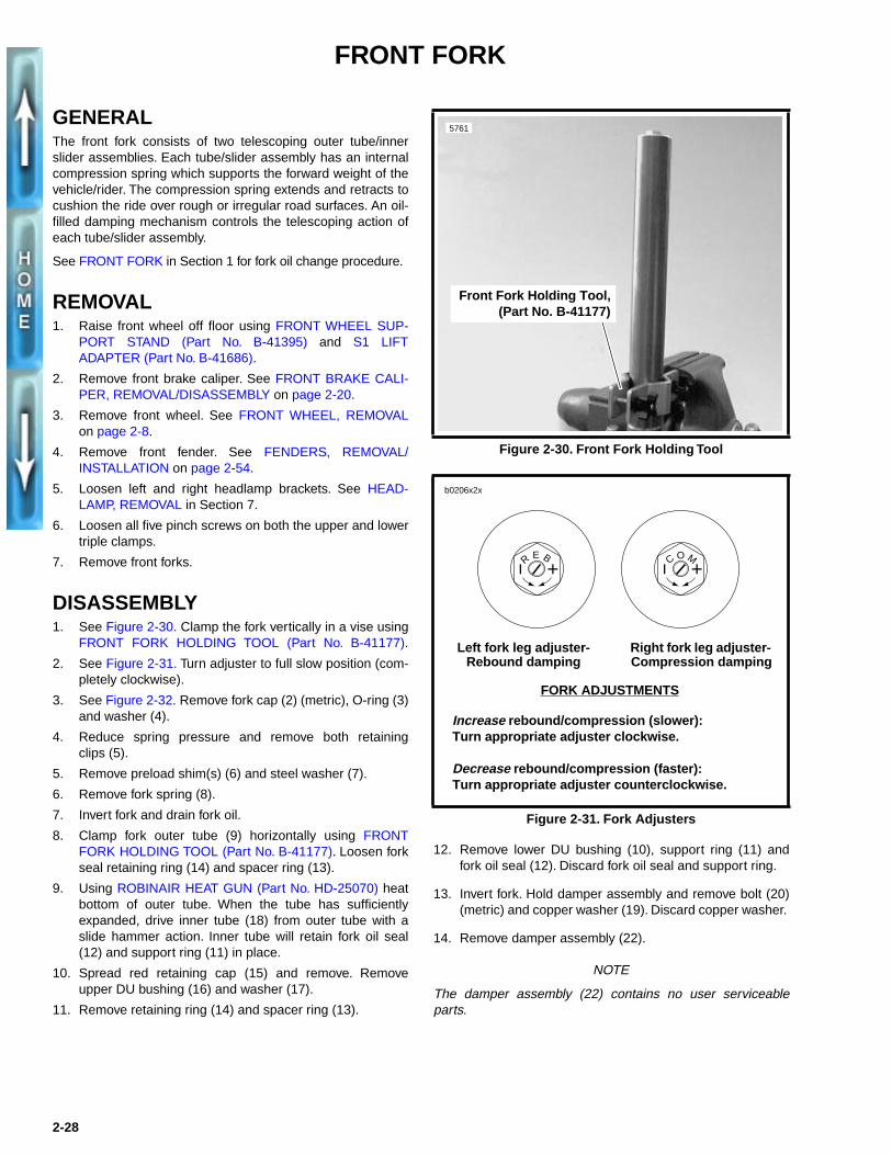
DISASSEMBLY 1. See Figure 2-30. Clamp the fork vertically in a vise using
FRONT FORK HOLDING TOOL (Part No. B-41177).
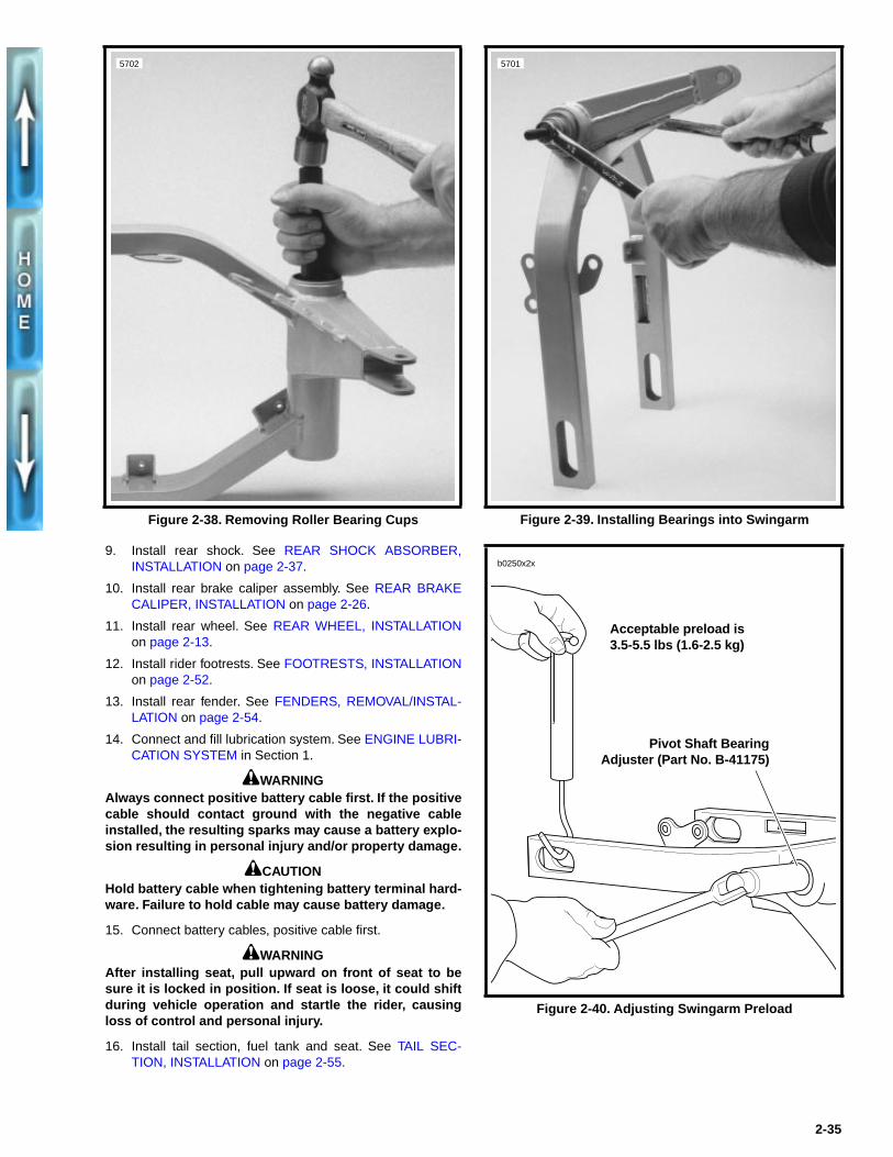
2. See Figure 2-31. Turn adjuster to full slow position (com-pletely clockwise).
3. See Figure 2-32. Remove fork cap (2) (metric), O-ring (3)and washer (4).
4. Reduce spring pressure and remove both retainingclips (5).
5. Remove preload shim(s) (6) and steel washer (7).
6. Remove fork spring (8).
7. Invert fork and drain fork oil.
8. Clamp fork outer tube (9) horizontally using FRONTFORK HOLDING TOOL (Part No. B-41177). Loosen forkseal retaining ring (14) and spacer ring (13).
9. Using ROBINAIR HEAT GUN (Part No. HD-25070) heatbottom of outer tube. When the tube has sufficientlyexpanded, drive inner tube (18) from outer tube with aslide hammer action. Inner tube will retain fork oil seal(12) and support ring (11) in place.
10. Spread red retaining cap (15) and remove. Removeupper DU bushing (16) and washer (17).
11. Remove retaining ring (14) and spacer ring (13).
12. Remove lower DU bushing (10), support ring (11) andfork oil seal (12). Discard fork oil seal and support ring.
13. Invert fork. Hold damper assembly and remove bolt (20)(metric) and copper washer (19). Discard copper washer.
14. Remove damper assembly (22).
NOTE
The damper assembly (22) contains no user serviceableparts.
Figure 2-30. Front Fork Holding Tool
Figure 2-31. Fork Adjusters
Front Fork Holding Tool,(Part No. B-41177)
5761
R E B C O M
Right fork leg adjuster- Compression damping
Left fork leg adjuster- Rebound damping
b0206x2x
FORK ADJUSTMENTS
Increase rebound/compression (slower):Turn appropriate adjuster clockwise.
Decrease rebound/compression (faster): Turn appropriate adjuster counterclockwise.
2-28

Figure 2-32. Front Forks
1. Front fork assembly2. Fork cap3. O-ring4. Washer5. Retaining clip (2)6. Preload shim
7. Steel washer8. Spring9. Outer tube10. DU bushing (lower)11. Support ring12. Fork oil seal
13. Spacer ring14. Retaining ring15. Retaining cap (red)16. DU bushing (upper)17. Washer18. Inner tube
19. Copper washer20. Bolt (metric)21. Bolt (2) (metric)22. Damper assembly
b0033a2x
1
2019
21
11
13
2
3
5
4
67
8
9 22
NOTE● Quantities are listed per individual fork leg.
● Left leg controls rebound damping. Right leg controls compression damping.
● Number of preload shims (6) may vary between fork assemblies.
10
12
14
15
16
17
18
2-29

CLEANING, INSPECTION AND REPAIR1. Thoroughly clean and inspect all parts. Replace any
parts that are bent, broken or damaged.
2. Inspect the O-rings for damage, wear or general deterio-ration; replace as necessary. Replace all other removedseals.
3. See Figure 2-32. Check inner tube (18). Tube surfaceshould be shiny, smooth and free of scoring or abrasions.
ASSEMBLY1. Install new fork seal retaining ring (14) and spacer ring
(13) on inner tube.
2. See Figure 2-33. Using FRONT FORK BUSHING/SEALINSTALLER (Part No. B-41176), install new fork oil sealon inner tube. External spring on fork oil seal faces bot-tom of fork leg.
3. See Figure 2-32. Install new support ring (11).
4. Install upper DU bushing (16) with large end towards thebottom of the fork leg. Install washer (17) and lower DUbushing (10). Install red retaining cap (15).
NOTEInspect both DU bushings upon assembly. Bushings arebronze with a Teflon layer. A DU bushing should be replacedwhen 20-30% of the Teflon layer has been worn through. Inthis circumstance, a visual inspection will show 20-30% of thebronze base. Also replace bushings if bushing interiors showany small grooves. Such grooves will damage the outside sur-face of the inner tubes.
5. Clamp outer tube (9) upside down using FRONT FORKHOLDING TOOL (Part No. B-41177).
6. See Figure 2-34. Place inner tube assembly inside outertube. Using bushing side of FRONT FORK BUSHING/SEAL INSTALLER (Part No. B-41176), drive in DU bush-ings until fully seated.
7. Reverse FRONT FORK BUSHING/SEAL INSTALLER.(Part No. B-41176). Seat fork oil seal with seal side oftool. Drop seal retaining ring in place. Fully seat retainingring.
8. See Figure 2-32. Clamp fork in a horizontal position.Install damper assembly (22) using bolt (20) (metric) anda new copper washer (19). Tighten bolt to 18-23 ft-lbs(24.4-31.2 Nm).
9. Clamp fork upright in the fully compressed stage.
10. Fill fork with oil. See FRONT FORK in Section 1.
11. Install fork spring (8).
12. Pull damper assembly above fork spring. Place steelwasher (7) and preload shim(s) (6) on top of spring.
13. Installing the retaining clips (5) requires two people.Have one person compress the spring, steel washer andpreload shim(s). At the same time, have the second per-son install both retaining clips.
14. Install washer (4), new O-ring (3) and fork cap (2) (metric).
Figure 2-33. Installing New Fork Seal Using Front Fork Bushing/Seal Installer (Part No. B-41176)
Figure 2-34. Installing Bushings and Seals Using Front Fork Bushing/Seal Installer (Part No. B-41176)
5760
Slide fork seal over installer
5759
Use tool to fullyseat DU bushings
2-30

INSTALLATION
1. Insert fork assembly through front fork triple clamps andheadlamp brackets.
NOTE
When installing the front forks, use a screwdriver to pry apartthe triple clamps.
2. See Figure 2-35. Position fork tubes so that top of eachfork cap fits flush with the top surface of upper tripleclamp.
3. Spread LOCTITE ANTI-SEIZE on the last three threadsof all five front fork triple clamp pinch screws. Tightenscrews to 18-20 ft-lbs (24.4-27.1 Nm).
4. Position headlamp bracket 2.375 in. (60.3 mm) abovelower triple clamp. Tighten headlamp bracket screws.
5. Install front fender. See FENDERS, REMOVAL/INSTAL-LATION on page 2-54.
6. Install front wheel. See FRONT WHEEL, INSTALLATIONon page 2-10.
7. Install front brake caliper. See FRONT BRAKE CALI-PER, INSTALLATION on page 2-21.
8. Set rebound and compression adjusters to the desiredsettings.
Figure 2-35. Aligning Front Forks
Flush
5517
2.375 in. (60.3 mm)
2-31

FORK STEM AND BRACKET ASSEMBLY
REMOVAL/DISASSEMBLY1. Remove fork assemblies. See FRONT FORK, REMOVAL
on page 2-28.
2. See Figure 2-36. Remove fork stem bolt (1) and uppertriple clamp (2).
3. Remove upper dust shield (3) and upper rollerbearing (4).
4. Lower the lower triple clamp (6). The lower bearing coneis a press fit on fork stem. Chisel through outer bearingcage to allow rollers to fall free. Apply heat to remove theremaining portion of bearing cone. Continuously moveflame around its entire circumference until bearing fallsfree. Remove lower dust shield (3).
5. If replacement of bearing cups (5) is necessary, drivecups from steering head using STEERING HEAD BEAR-ING RACE REMOVER (Part No. HD-39301A) and UNI-VERSAL DRIVER HANDLE (Part No HD-33416).
CLEANING, INSPECTION AND REPAIRSee FRONT FORK in Section 1 for adjustment procedures.
1. See Figure 2-36. Clean the dust shields (3), bearingcups (5), fork stem and lower triple clamp (6) and framewith solvent.
2. Carefully inspect bearing races and assemblies for pit-ting, scoring, wear and other damage. Replace damagedbearing as a set.
3. Check the fork stem and lower triple clamp (6) for dam-age. Replace damaged fork stem.
ASSEMBLY/INSTALLATION 1. See Figure 2-36. If removed, install new bearing cups (5)
into frame steering head using STEERING HEAD BEAR-ING RACE INSTALLER (Part No. HD-39302).
2. Liberally coat the bearing cones (4) with grease usingWHEEL BEARING PACKER TOOL (Part No. HD-33067).Work the grease into the rollers.
3. Place lower bearing dust shield (3) over fork stem. Find asection of pipe having an inside diameter slightly largerthan the outside diameter of the fork stem. Press bearingcone (4) onto fork stem and bracket (1) using the pipe asa press on tool.
4. Insert lower triple clamp (6) through the steering head.Install the upper bracket bearing (4) and dust shield (3)onto fork stem.
5. Install the upper triple clamp (2) and loosely install forkstem bolt (11).
6. Install fork assemblies. See FRONT FORK, INSTALLA-TION on page 2-31.
7. Tighten the fork stem bolt (1) until the bearings have nofreeplay. Make sure the fork stem turns freely, thentighten the fork stem clamp screw (rearmost pinch screwon upper triple clamp).
8. Check bearing adjustment. See FRONT FORK,ADJUSTMENT in Section 1.
Figure 2-36. Bearing Cup Removal
1
2
34
5
543
6 7
9
8
1. Fork stem bolt2. Upper triple clamp3. Dust shield (2)4. Roller bearing (2)5. Bearing cup (2)
6. Lower triple clamp7. Screw (5)8. Steering head lock9. Steering lock key
b0031a2x
2-32

SWINGARM
REMOVAL
NOTE
Mark all hardware as it is removed so that it may be returnedto its original location.
1. Swingarm removal requires motorcycle to be supportedin several areas. First, secure front wheel and then raiserear wheel off ground with REAR WHEEL SUPPORTSTAND (Part No. B-41174).
1WARNING
To avoid accidental start-up of vehicle and possible per-sonal injury, disconnect the battery cables before pro-ceeding. Always disconnect the negative cable first. Ifthe positive cable should contact ground with the nega-tive cable installed, the resulting sparks may cause a bat-tery explosion producing personal injury.
1CAUTION
Hold battery cable when loosening battery terminal hard-ware. Failure to hold cable may cause battery damage.
2. Disconnect both battery cables, negative cable first.
3. Remove seat, fuel tank and tail section. See TAIL SEC-TION, REMOVAL on page 2-55.
4. Drain oil tank and remove filter. Detach feed, vent andreturn hoses from oil tank. See ENGINE LUBRICATIONSYSTEM in Section 1.
5. Support motorcycle frame with a floor hoist such as theCENTRAL HYDRAULICS FOLDING CRANE (Model T-5466).
6. Remove rear fender. See FENDERS, REMOVAL/INSTALLATION on page 2-54.
7. Remove rear brake caliper assembly from swingarm.See REAR BRAKE CALIPER, REMOVAL/DISASSEM-BLY on page 2-25.
8. Remove rear wheel. See REAR WHEEL, REMOVAL onpage 2-11.
9. Remove rear shock. See REAR SHOCK ABSORBER,REMOVAL on page 2-36.
10. Remove rider footrests. See FOOTRESTS, REMOVALon page 2-52.
11. Remove air cleaner assembly. See AIR CLEANER,REMOVAL in Section 4.
12. Remove carburetor. See CARBURETOR, REMOVAL inSection 4.
13. Remove muffler and exhaust header. See EXHAUSTSYSTEM, REMOVAL/DISASSEMBLY on page 2-50.
14. Support engine under crankcase. Avoid pushing tie barassembly upward.
15. Place a crating strap between the engine cylinders andaround the lift. Tighten crating strap until snug.
16. Detach tie bars from frame mounts in the followingsequence. Do not remove tie bars from engine.
a. Rear tie bar. Use a swivel socket.
b. Top tie bar.
c. Front tie bar and clutch cable clamp.
17. See Figure 2-37. Remove isolator screws (9) and wash-ers on each side.
18. Slowly raise floor hoist until rubber isolators (10) can beremoved. Frame will rise while engine and swingarmremain secured to lift by crating strap.
19. Loosen one pinch screw (8) on the swingarm mountblock (7).
20. Remove bearing adjusting bolt (1) on that side withPIVOT SHAFT BEARING ADJUSTER (Part No. B-41175).
21. Loosen the remaining pinch screw. Extract pivot shaft (5)and second adjuster as an assembly.
22. Remove swingarm.
DISASSEMBLY
1CAUTIONCarefully mark all bearing components as they areremoved, so that they may be returned to their originallocations. Do not intermix bearing components.
1. See Figure 2-37. Remove and discard swingarm seal (2).
2. Remove roller bearings (3).
NOTERemove roller bearing cups (4) only if replacement isrequired. The complete bearing assembly must be replacedas a unit when replacement is necessary. Do not intermixbearing components.
3. See Figure 2-38. Carefully press roller bearing cups (4)from swingarm using STEERING HEAD BEARINGRACE REMOVER (Part No. HD-39301A) and UNIVER-SAL DRIVER HANDLE (Part No. HD-33416).
CLEANING/INSPECTION1. Clean all components in solvent and blow dry. Carefully
inspect all bearing components for wear and/or corro-sion. Replace complete bearing assembly if any compo-nent is damaged.
2. Check that swingarm is not bent or twisted. Replace ifdamaged.
ASSEMBLY1. See Figure 2-39. If necessary, draw new roller bearing
cups (4) into swingarm using BEARING INSTALLATIONBOLT (Part No. B-35316-5) and STEERING HEADBEARING RACE INSTALLER (Part No. HD-39302).
2-33

Figure 2-37. Swingarm Assembly and Swingarm Mount Block
21
3 4
6
7
8
5
1. Bearing adjusting bolt (2)2. Swingarm seal (2)3. Roller bearing (2)4. Roller bearing cup (2)5. Pivot shaft6. Swingarm7. Swingarm mount block8. Pinch screw (2)9. Isolator screw (2)10. Rubber isolator (2)
b0210x2x
9
NOTE
Timkin roller bearing assemblies should be replaced as aunit. Do not intermix components. Mark all components sothey may be correctly installed.
2. Coat bearing components with WHEEL BEARINGGREASE (Part No. HD-99855-89) and assemble.
1CAUTION
Pivot shaft (5) must be installed between inner races (3)or bearing failure can result.
3. Install a new swingarm seal (2) flush to the swingarm.
4. Apply LOCTITE ANTI-SEIZE LUBRICANT to pivot shaftthreads.
5. Install one bearing adjustment bolt (1) into pivot shaft (5).Bottom out the adjustment bolt.
6. Slide swingarm assembly into position.
7. Slide pivot shaft assembly through mount block andswingarm. Install the opposing bearing adjustment bolt(1) using PIVOT SHAFT BEARING ADJUSTER (Part No.B-41175).
8. Tighten one pinch screw (8) into swingarm mount block.Do not tighten the other pinch screw (8) at this time.
2-34
INSTALLATION1. Adjust swingarm preload. Using a scale as shown in Fig-
ure 2-40. Preload should measure 3.5-5.5 lbs (1.6-2.5 kg).
2. Remove both pinch screws (8). Apply LOCTITETHREADLOCKER 242 (blue) to pinch screw threads.
3. Check that swingarm is centered between mounts.Torque pinch screws (8) to 27-30 ft-lbs (36.6-40.7 Nm).
4. Install rubber isolators and bolts. See SECONDARYDRIVE BELT in Section 6.
5. Attach tie bars to the frame in the following order. Torqueto 30-33 ft-lbs (40.7-44.7 Nm)
a. Front tie bar. Clutch cable clamp holds cable on aircleaner side of motor.
b. Top tie bar.
c. Rear tie bar. Tie bar must be horizontal and belowframe tab.
6. Install carburetor. See CARBURETOR, INSTALLATIONin Section 4.
7. Install muffler and exhaust header. See EXHAUST SYS-TEM, ASSEMBLY/INSTALLATION on page 2-50.
8. Install air cleaner. See AIR CLEANER, INSTALLATION inSection 4.
9. Install rear shock. See REAR SHOCK ABSORBER,INSTALLATION on page 2-37.
10. Install rear brake caliper assembly. See REAR BRAKECALIPER, INSTALLATION on page 2-26.
11. Install rear wheel. See REAR WHEEL, INSTALLATIONon page 2-13.
12. Install rider footrests. See FOOTRESTS, INSTALLATIONon page 2-52.
13. Install rear fender. See FENDERS, REMOVAL/INSTAL-LATION on page 2-54.
14. Connect and fill lubrication system. See ENGINE LUBRI-CATION SYSTEM in Section 1.
1WARNINGAlways connect positive battery cable first. If the positivecable should contact ground with the negative cableinstalled, the resulting sparks may cause a battery explo-sion resulting in personal injury and/or property damage.
1CAUTIONHold battery cable when tightening battery terminal hard-ware. Failure to hold cable may cause battery damage.
15. Connect battery cables, positive cable first.
1WARNINGAfter installing seat, pull upward on front of seat to besure it is locked in position. If seat is loose, it could shiftduring vehicle operation and startle the rider, causingloss of control and personal injury.
16. Install tail section, fuel tank and seat. See TAIL SEC-TION, INSTALLATION on page 2-55.
Figure 2-38. Removing Roller Bearing Cups
5702
Figure 2-39. Installing Bearings into Swingarm
Figure 2-40. Adjusting Swingarm Preload
5701
b0250x2x
Acceptable preload is 3.5-5.5 lbs (1.6-2.5 kg)
Pivot Shaft BearingAdjuster (Part No. B-41175)
2-35

REAR SHOCK ABSORBER
GENERAL See Figure 2-41. The rear suspension features a WP Suspen-sion shock absorber. The shock adjusts for compression andrebound damping as well as spring preload.
The most important rear shock adjustment is the preload set-ting. Before making any suspension adjustments, set theproper preload. This procedure can be found under SUSPEN-SION ADJUSTMENTSon page 2-39.
NOTERear shock absorber contains no user serviceable parts.
REMOVAL1. Lift rear wheel off ground using REAR WHEEL SUP-
PORT STAND (Part No. B-41174).
2. Remove seat, fuel tank and tail section. See TAIL SEC-TION, REMOVAL on page 2-55.
3. Support motorcycle frame with a floor hoist such as theCENTRAL HYDRAULICS FOLDING CRANE.
4. See Figure 2-41. Use a flex socket and extension toremove allen screw on front reservoir clamp (3).
5. Remove allen screw and locknut (4) (metric) on frontmounting point.
6. Remove allen screw and locknut (1) (metric) on rearmount while supporting shock absorber.
7. Loosen rear reservoir clamp (2).
8. Remove shock absorber assembly.
DISASSEMBLY
1WARNINGThe following steps require using a press. Wear eye pro-tection and make certain set-up is stable. The forceinvolved could cause parts to “flyout” at great speedscausing personal injury.
1. See Figure 2-42. Place rear shock absorber in a hydrau-lic press with REAR SHOCK COMPRESSING TOOL(Part No. B-41178-A) on rear drawing ring.
2. Apply pressure to compress shock spring. Loosen andremove preload adjusting nuts (metric).
3. Release pressure. Remove REAR SHOCK COM-PRESSING TOOL (Part No. B-41178-A) and shock frompress.
4. See Figure 2-43. Remove rear drawing ring (2).
5. Remove support ring (3) and bump rubber (4).
6. Remove circlip (5) on end of shock cartridge.
7. Remove steel spring retainer (6).
8. Remove spring (7).
Figure 2-41. Rear Shock Mounting Hardware
Figure 2-42. Compressing Rear Shock
1. Rear allen screw and locknut (metric)2. Rear reservoir clamp3. Front reservoir clamp 4. Front allen screw and locknut (metric)
1
2 3
4
5541a
Rear Shock CompressingTool (Part No. B-41178-A)
5129a
Preload adjustingnuts (metric)
Rear drawing ring
Hydraulic press
Front drawing ring
2-36

ASSEMBLY1. See Figure 2-43. Install spring (7).
2. Install steel spring retainer (6).
3. Install circlip (5) on end of shock cartridge.
4. Install bump rubber (4) and support ring (3).
1WARNINGThe following steps require using a press. Wear eye pro-tection and make certain set-up is stable. The forceinvolved could cause parts to “flyout” at great speedscausing personal injury.
5. See Figure 2-42. Place rear shock absorber in a hydrau-lic press with REAR SHOCK COMPRESSING TOOL(Part No. B-41178-A) on rear drawing ring.
6. Apply pressure to compress shock spring. Install rearpreload adjusting nuts (metric).
7. Release pressure. Remove REAR SHOCK COM-PRESSING TOOL (Part No. B-41178-A) and shock frompress.
INSTALLATION1. See Figure 2-41. Loosely install reservoir clamps (2, 3).
2. With banjo bolt facing upward, place shock in mounts andloosely install front allen screw and locknut (4) (metric).
3. Loosely install rear allen screw and locknut (1) (metric).Tighten reservoir clamp hardware (2, 3).
4. Tighten front and rear allen screws (1, 4) (metric) to 40-45 ft-lbs (54.2-61.0 Nm).
1WARNING
After installing seat, pull upward on front of seat to besure it is locked in position. If seat is loose, it could shiftduring vehicle operation and startle the rider, causingloss of control and personal injury.
5. Install tail section, fuel tank and seat. See TAIL SEC-TION, INSTALLATION on page 2-55.
6. Check rear shock preload. See SUSPENSION ADJUST-MENTS on page 2-39.
Figure 2-43. Rear Shock
3
1. Preload adjusting nut (2) (metric)
2. Drawing ring, rear3. Support ring4. Bump rubber5. Circlip6. Spring retainer (steel)7. Spring8. Rod (2)9. Spring retainer (nylon)10. Drawing ring, front11. Shock mount and
hardware12. Seal (4)13. Bushing (2)14. Heim joint (2)15. Adaptor bushing (2)16. Clamp17. Clamp w/nut and
washer
1
23
45
6
7
910
8
11
1514 13
12
12
16
17
b0213x2x
2-37

SUSPENSION THEORY
DEFINITIONS
● Compression: Suspension is compressed when thewheel moves upward.
● Damping: Resistance to movement. Damping affectshow easily the suspension can move and limits oscilla-tion of the system once movement has begun.
● Preload: The spring is compressed somewhat duringassembly. This initial compression provides a “loaded”condition in the spring. This compression is referred to aspreload.
● Rebound: The suspension is rebounding when it is mov-ing back from being compressed.
GENERAL
1WARNING
Before evaluating and adjusting suspension settings,check the motorcycle’s tires. Tires must be in good con-dition and properly inflated. Failure to check the tiresmay cause personal injury.
See Figure 2-44 and Figure 2-45. The rear suspension fea-tures a WP Suspension shock absorber that adjusts for com-pression and rebound damping as well as spring preload.
See Figure 2-46. The front suspension uses WP Suspensioninverted forks that adjust for compression and rebound damp-ing. These forks offer strength and stiffness for improved slid-ing action, better shock absorption and compliance with theroad.
If the preload adjustment is correct, and you have therebound and compression damping set at the factory recom-mended points the motorcycle should handle and ride prop-erly. If you are unhappy with these settings they can bechanged according to the following procedures.
NOTE
Evaluating and changing the rebound and compressiondamping is a very subjective process. Many variables affectmotorcycle handling under different circumstances. Changesshould be approached carefully.
Figure 2-44. Rear Shock Rebound Adjuster
Figure 2-45. Rear Shock Compression Adjuster
Figure 2-46. Front Fork Adjusters
5572
7 adjustments
5571
12 adjustments
5542
Front fork rebounddamping adjuster
Front fork compressiondamping adjuster
2-38

SUSPENSION ADJUSTMENTS
REAR SHOCK PRELOADRear shock spring preload must be adjusted before any otheradjustments can be attempted. This adjustment assures therear suspension has the proper amount of travel for the rider’sweight. This setting should be made before the motorcycle isridden any distance. Your Buell dealer can assist you with rearshock spring preload settings.
Improper preload will adversely affect both the handling andthe ride of the motorcycle. Correct setting of preload willresult in a motorcycle that suits the rider’s size and weight.
You will need three people to carry out this adjustment.
1. Verify correct front and rear tire pressure. See SPECIFI-CATIONS on page 2-1.
2. Remove all accessories from motorcycle including tankbag and/or saddlebags.
3. Take the motorcycle off the side stand and bounce therear up and down a few times to be sure the suspensionis free and not binding.
4. See Figure 2-47. Measure the distance from the centerof the rear axle nut to the rear turn signal mounting boltwithout rider/passenger/cargo/accessories on the motor-cycle.
5. Install items removed in Step 2. Load all cargo.
6. Bounce a few times on the seat to be sure the suspen-sion is free and not binding.
7. With the help of an assistant, take the same measure-ment with the vehicle fully loaded (rider/passenger/lug-gage/cargo). The assistant should help balance themotorcycle so the rider can keep both feet on the foot-rests.
8. Subtract the second measurement from the first. The dif-ference, which is the squat, should be 0.25-0.75 in. (6.4-19.1 mm). If it is not, you will have to adjust the springpreload.
1CAUTION● Be sure to apply the same number of turns to each
mechanical preload adjusting nut to ensure that theend plates do not become misaligned. Misalignedend plates will cause the shock absorber spring tobind against the adjustment rods.
● Be sure the plates are parallel within 1/64 in. (0.4 mm).Misaligned end plates will cause the shock absorberspring to bind against the adjustment rods.
9. See Figure 2-48. Change the spring preload by adjustingthe mechanical preload adjusting nuts (metric) on therods that connect the end plates.
a. Increase the preload by tightening the nuts.
b. Decrease the preload by loosening the nuts.
Figure 2-47. Checking Rear Preload
Figure 2-48. Adjusting Rear Preload
Rear turn signal mounting bolt
Rear axle nut
5540
Preload adjusting nuts (metric)
2-39
ADJUSTMENTSEvaluating and changing the rebound and compressiondamping is a very subjective process. A good performing sus-pension finds a proper balance between spring, spring pre-load, damping, track conditions and riding speed. However,all settings are at best a compromise. If a rider fails to find agood set-up, go back to the factory recommended settingsand start over again.
Make all suspension adjustments in one or two click incre-ments. Adjusting more than one or two clicks at a time maycause you to skip the best adjustment. Test ride after eachadjustment. When an adjustment makes no difference, returnto the previous adjustment and try a different approach.
To find the optimum settings you will need the preload prop-erly adjusted, the tires properly inflated and a familiar bumpyroad. It is useful if the road contains a variety of differentbumps from small sharp bumps such as potholes or frostheaves to large undulations. Begin the process by putting allthe damping adjustments at the factory recommended set-tings. Ride the bike over a variety of different surfaces andbumps at different speeds. When the suspension is set prop-erly the motorcycle will be stable and comfortable.
Rear Suspension Adjustments
Beyond the rear preload adjustment, the rear shock can alsobe adjusted for rebound and compression damping. However,it is important to note the rear preload must be set correctlybefore performing any other adjustments.
See Table 2-6. The compression damping adjuster has 11possible settings. Adjust compression damping by using theblack dial at the rear of the shock. Position #1 sets the mini-mum amount of compression damping. This is the softest set-ting. Position #11 maximizes compression damping. Thefactory recommended setting is Position #5.
The rebound damping adjuster has 7 possible settings.Changes are made using the dial on the remote nitrogen res-ervoir. When set to Position #1, the rear shock exhibits mini-mum rebound damping. At this setting, the shock will have avery fast rebound. Position #7 sets the rear shock to maxi-mum rebound damping. The factory recommended setting isPosition #3.
Front Suspension Adjustments
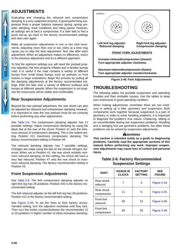
See Table 2-6. The fork compression damping adjuster onright fork leg has 28 positions. Position #20 is the factory rec-ommended setting.
The fork rebound adjuster on the left fork leg has 28 positions.Position #12 is the factory recommended setting.
See Figure 2-49. To set the forks to their factory recom-mended setting, turn the adjusters clockwise until they lock.Then turn the knobs counterclockwise the recommended 12or 20 positions. A higher number of clicks increases damping.
TROUBLESHOOTINGThe following tables list possible suspension and operatingtroubles and their probable causes. Use the tables to keepyour motorcycle in good operating condition.
When making adjustments, remember there are two medi-ums in setting up a bike, geometry and suspension. Bothcomponents work together because suspension is a part ofgeometry. In order to solve handling problems, it is importantto diagnose the problem’s true nature. Chattering, sliding oran uncomfortable feeling are suspension problems. Handlingand a swinging fork are geometric problems, but often theseproblems can be solved by suspension adjustments.
1WARNINGThis section is intended solely as a guide to diagnosingproblems. Carefully read the appropriate sections of thismanual before performing any work. Improper suspen-sion adjustments may cause loss of control and personalinjury.
Figure 2-49. Fork Adjustments
Table 2-6. Factory Recommended Suspension Settings
PARTRANGE IN
CLICKSFACTORY SETTING
SEE FIGURE
Rear shock rebound
7 3 Figure 2-44.
Rear shock compression
11 5 Figure 2-45.
Front fork rebound
28 12 Figure 2-46.
Front forkcompression
28 20 Figure 2-46.
R E B C O M
Right fork leg adjuster- Compression damping
Left fork leg adjuster- Rebound damping
b0206x2x
FRONT FORK ADJUSTMENTS
Increase rebound/compression (slower):Turn appropriate adjuster clockwise.
Decrease rebound/compression (faster): Turn appropriate adjuster counterclockwise.
2-40

Table 2-7. General Suspension Problems
TROUBLESHOOTING CONDITION ADJUSTMENT SOLUTION
Bike wallows through turns.Feels loose or vague after bumps.Wheel tends to “pogo” after passing over a bump. This is noticeable by watching the bike continue to bounce as it travels over multiple bumps.
Increase rebound damping.
Wheel responds to bump, but doesn’t return to ground quickly after bumps. This is more pronounced over a series of bumps and is often referred to as “packing down.”
Reduce rebound damping.
The bike bottoms out or dips while cornering.Bike has excessive brake dive.
Increase compression damping.
Harsh ride particularly over washboard surfaces.Bumps kick through handlebars or seat.Suspension seems not to respond to bumps. This is evidenced by tire chattering (a movement with short stroke and high frequency) through corners or by jolting the rider over rough roads.
Reduce compression damping.
Table 2-8. Rear Suspension Problems
TROUBLESHOOTING CONDITION ADJUSTMENT SOLUTION
“Pumping on the Rear” occurs when you are accelerating out of a corner. This problems occurs in two varieties.1. The first type has a movement with a long stroke and a high
frequency.
2. The second version has a movement with a short stroke andhigh frequency.
1. The shock is too soft. Increase compressiondamping. If the adjuster is already set to the maxi-mum, add more preload to the spring (one turnmaximum).
2. In this case the shock is too hard. Decrease com-pression damping.
Chattering during braking. Decrease the compression damping. If the problem persists, decrease rebound damping for a faster rebound rate. Less spring preload may also help.
Lack of tire feedback. The suspension is too soft. Increase compression damping.
Sliding during cornering. Sliding may occur going into the corner or accelerating out of the corner.
The suspension is too hard. Decrease compression damping.
Table 2-9. Front Suspension Problems
TROUBLESHOOTING CONDITION ADJUSTMENT SOLUTION
Not absorbing bumps. A good suspension is a balance between damping and track condition. Finding this balance requires exploring all possible compression settings.
Lack of tire feedback. Increase compression damping.
Tire slides. Decrease compression damping.
2-41

Table 2-10. Rider Suspension Preferences NOTE
All adjustments require rear shock preload to be properly adjusted for the rider’s size and weight. For information on setting rearshock preload, see SUSPENSION ADJUSTMENTS, REAR SHOCK PRELOAD in this section.
DATEFRONT FORK
REBOUNDFRONT FORK
COMPRESSIONREAR SHOCK
COMPRESSIONREAR SHOCK
REBOUNDRESULTS
Position #12 Position #20 Position #5 Position #3 Factory recommended settings.
2-42

THROTTLE CONTROL
REMOVAL/DISASSEMBLY 1. See Figure 2-50. Slide rubber boot (5) off the cable
adjusters (2). Loosen jam nut (metric) on each adjuster.
2. Remove two screws (1) (metric). Separate housings fromhandlebar.
3. See Figure 2-51. Unhook ferrules (7) from cable wheel (8).
4. Remove cables from under cable guide (6).
5. Remove cables from housings (5, 9) by loosening cableadjusters (2) (metric).
6. Remove air cleaner assembly. See AIR CLEANER,REMOVAL in Section 4.
7. Disconnect cables from carburetor.
8. Remove cables from motorcycle.
CLEANING, INSPECTION AND REPAIRClean all parts in a non-flammable cleaning solvent. Blow drywith compressed air. Replace cables if frayed, kinked or bent.
ASSEMBLY/INSTALLATION1. See Figure 2-51. Screw cable assemblies (3, 4) into
housings (5, 9). Throttle control cable (4) has a larger fit-ting end and is positioned inside the front housing (5).Idle control cable (3) has a smaller fitting end and is posi-tioned inside the rear housing (9).
2. Run cables in grooves on cable guide (6).
3. Attach ferrules (7) to cable wheel (8). When properlyassembled, notches for ferrules will be at 12 o’clock.
4. Position housings on right handlebar by engaging locat-ing pin (10) on front housing with hole in handlebar.Attach housings with screws (1) (metric). Tighten to 12-17 in-lbs (1.4-1.9 Nm).
5. Route idle and throttle control cables.
a. Cables must be routed forward from throttle controlgrip, forward of upper triple clamp and down and tothe left.
b. Continue between side of frame steering head andleft frame tube. Cables should be above and to theleft of the D-shaped washer behind the steeringhead.
c. Route cables below the fuel tank and above the hornmount. Continue downward to carburetor.
6. Install idle control cable into longer, inboard cable guideon carburetor.
7. Install throttle control cable into shorter, outboard cableguide on carburetor.
8. Adjust throttle cables. See CARBURETOR, CABLEADJUSTMENT in Section 1.
9. Install air cleaner. See AIR CLEANER, INSTALLATIONin Section 4.
Figure 2-50. Throttle Control Cables
Figure 2-51. Cable Connections
1. Screws (2) (metric)2. Cable adjusters (2)3. Idle control cable
5587
3 42
5
1
4. Throttle control cable5. Rubber boot
1. Screws (2) (metric)2. Cable adjusters (2)3. Idle control cable4. Throttle control cable5. Front housing
5719
6. Cable guide7. Ferrules8. Cable wheel9. Rear housing10. Locating pin
3 4
6
8 7
9 5
2
1
10
2-43

CLUTCH CONTROL
ADJUSTMENTSee CLUTCH in Section 1.
REMOVAL/DISASSEMBLY
Clutch Cable – Lower
1. Raise rear wheel off floor using REAR WHEEL SUP-PORT STAND (Part No. B-41174).
2. See Figure 2-52. Remove four TORX screws (1) withwashers and clutch inspection cover (2). Do not damageor dislodge quad ring (14) in primary cover (11).
3. Slide spring (3) with attached hex lockplate (4) from flatsof adjusting screw (12).
4. Turn adjusting screw clockwise to release ramp and cou-pling mechanism. As the adjusting screw is turned, rampassembly moves forward. Unscrew nut (5) from end ofadjusting screw.
5. Remove hook of ramp (6) from button at the rear of cableend coupling (16). Remove cable end (10) from slot incoupling.
6. Turn cable end fitting (9) counterclockwise to removeclutch cable lower section from primary cover (11).Remove O-ring (8) from cable end fitting.
Clutch Hand Control
1. See Figure 2-53. Detach clutch switch (7) as follows.
a. Remove screw (8).
b. Depress clutch lever and hold.
c. Detach switch by depressing switch trigger buttonand pulling switch towards the end of the handlebar.
NOTEThe individual parts of the clutch switch are not serviceable.Replace switch upon failure.
2. Remove bolt (2) (metric) and nut (6) (metric).
3. Remove handlever from clutch clamp (5). Detach clutchcable from handlever.
4. Slide clutch cable out of wire guide (10) on right fork leg.
5. Remove clutch cable clamp (11) from frame.
6. Remove clutch clamp as follows.
a. Cut off left handgrip.
b. Remove left handlebar switch housing. See HAN-DLEBAR SWITCHES in Section 7.
c. Detach mirror mounting hardware (metric, left handthreads).
d. Remove clamp screw (4) (metric). Slide clamp offthe end of the handlebar.
Figure 2-52. Clutch Release Mechanism
1. TORX screw with washer (4)2. Clutch inspection cover3. Spring 4. Adjusting screw lockplate5. Nut6. Outer ramp7. Ball (3)8. O-ring9. Cable end fitting10. Clutch cable end11. Primary cover12. Clutch adjusting screw
assembly13. Retaining ring14. Quad ring15. Inner ramp16. Coupling
b0131x6x
1
2 34 5
67
16
15
8
9
10
11
12
13
14
NOTEOuter ramp (6) and coupling (16) configura-tion may vary. See CLUTCH in Section 1.
2-44

ASSEMBLY/INSTALLATION
Clutch Cable – Lower
1. See Figure 2-52. Install O-ring (8) over cable end fitting(9) of clutch cable lower section. Turn fitting clockwise toinstall into primary cover (11). Tighten fitting to 3-5 ft-lbs(4.0-6.8 Nm).
2. Fit coupling (16) over cable end. Place hook of ramparound coupling button and rotate assembly counter-clockwise until tang on inner ramp (15) fits in slot of pri-mary cover (11).
3. Thread nut (5) on adjusting screw (12) until slot of screwis accessible with a screwdriver. Fit nut hex into recess ofouter ramp (6) and turn adjusting screw counter-clock-wise.
4. If not yet performed, route clutch cable from hand gripacross front of upper triple clamp to right side, downbetween right fork leg and steering neck above lower tri-ple clamp. Continue down to left side of bike throughclamp along primary chaincase to clutch.
5. With clutch cable upper section connected to clutchlever, adjust primary chain tension. See PRIMARYCHAIN in Section 1.
6. Adjust clutch. See CLUTCH in Section 1.
Clutch Hand Control
1. See Figure 2-53. Attach clutch clamp (5) as follows.
a. Slide clamp over handlebar.
b. Install left switchgear housing. See HANDLEBARSWITCHES in Section 7.
c. Place clamp next to switchgear housing. Fasten tohandlebar with screw (4) (metric). Tighten screw to30-35 in-lbs (3.4-4.0 Nm).
d. Install mirror parallel to handlebars. Mirror mounthas metric, left hand threads.
e. Install a new left handgrip. See HANDLEBAR,INSTALLATION on page 2-49.
2. Connect end of clutch cable upper section to clutch han-dlever. Position lever within clutch clamp.
3. Apply small amount of LOCTITE ANTI-SEIZE LUBRI-CANT to bolt (2). Secure handlever with bolt (2) (metric)and nut (6) (metric).
4. Attach clutch switch (7) with screw (8).
5. If not yet performed, route clutch cable from hand gripacross front of upper triple clamp to right side, downbetween right fork leg and steering neck above lower tri-ple clamp. Continue down to left side of bike throughclamp along primary chaincase to clutch.
6. With clutch cable lower section connected to primarycover, adjust clutch. See CLUTCH in Section 1.
Figure 2-53. Clutch Hand Control
b0221x2x
3
1. Clutch handlever2. Bolt (metric)3. Mirror assembly4. Screw (metric)5. Clutch clamp6. Nut (metric)
7. Clutch switch8. Screw9. Clutch cable10. Wire guide11. Cable clamp
124
9
8
7
6
11
10
Remove switch (7
)5
2-45

SPEEDOMETER AND TACHOMETER
GENERALReplace the speedometer or tachometer if the unit is notworking properly. These instruments are not repairable. How-ever, before replacing the instrument check that the problemis not caused by a faulty cable or loose wire connection.
REMOVAL
Speedometer 1. Detach windscreen from mounts. See WINDSCREEN,
REMOVAL on page 2-56.
2. See Figure 2-54. Loosen and remove the speedometercable (5) from the speedometer.
3. Remove nuts and lockwashers (4) from speedometercover (1).
4. Straighten reset cable cotter pin and remove. Discardpin. Detach reset cable assembly from speedometer.
5. Remove cover. Remove wires from clamp inside cover.
6. Detach ground wire.
7. See Figure 2-55. Disconnect wire terminals from back ofspeedometer. Pull bulbs (3) from bores.
8. Remove speedometer (1) through front of instrumentsupport (8).
Tachometer 1. Detach windscreen from mounts. See WINDSCREEN,
REMOVAL on page 2-56.
2. See Figure 2-54. Remove nut and lockwasher (4) fromtachometer cover (2).
3. Remove nut on windscreen mount (3). Remove wind-screen mount from tachometer cover.
4. Remove tachometer cover.
5. Remove ground wires from bottom stud.
6. See Figure 2-55. Disconnect wire terminals from back oftachometer. Pull bulbs (3) from bores.
7. Remove tachometer (2) through front of instrument sup-port (8).
Instrument Support1. Remove speedometer and tachometer.
2. See Figure 2-55. Remove knurled nut (5), washer (6) andodometer reset cable.
3. Pull indicator lights assembly (4) out towards the head-lamp. Pull bezel (19) out towards the tail lamp.
4. Remove two screws (7).
5. Remove instrument support.
INSTALLATION
Speedometer1. See Figure 2-55. If removed, install instrument support
(8). Slide speedometer into instrument support.
2. Attach ground wire with screw and lockwasher.
3. Connect wire terminals on back of speedometer. Insertbulbs into bores at back of speedometer.
4. See Figure 2-54. Using a new cotter pin, connect resetcable assembly (6) to speedometer.
5. Place speedometer cover over speedometer. Tightennuts and lockwashers (4).
6. Connect speedometer cable (5) to speedometer.
7. Attach windscreen. See WINDSCREEN, INSTALLATIONon page 2-56.
Tachometer1. See Figure 2-55. If removed, install instrument support
(8). Slide tachometer into instrument support (8).
2. Connect wire terminals on back of tachometer. Insertbulbs into bores.
3. Attach ground wire.
4. See Figure 2-54. Slide tachometer cover (2) overtachometer. Install nut and lockwasher (4).
5. Install windscreen mount (3) with nut.
6. Attach windscreen. See WINDSCREEN, INSTALLATIONon page 2-56.
Instrument Support1. See Figure 2-55. Attach instrument support to mounts
using two screws (7). Tighten screws to 7-9 ft-lbs (9.5-12.2 Nm).
2. Install odometer reset cable using washer (6) andknurled nut (5).
3. Insert bezel (19) through instrument support. Attach indi-cator lights assembly (4) to bezel.
Figure 2-54. Instruments
57162
3
6
1. Speedometer cover2. Tachometer cover3. Windscreen mount
4. Nut and lockwasher (3)5. Speedometer cable6. Odometer reset cable
1
4
5
2-46

Figure 2-55. Speedometer and Tachometer
1. Speedometer2. Tachometer3. Bulb4. Indicator light assembly5. Knurled nut6. Washer7. Screw (2)
8. Instrument support9. Odometer reset cable10. Cotter pin11. Rubber cushion (2)12. Speedometer cover13. Tachometer cover14. Lockwasher (3)
15. Nut (2)16. Wire guide17. Speedometer drive18. Speedometer cable19. Indicator lamp bezel
b0214x2x
1
2
3
4
19
5 6 8
9
11
10
12
14
15
14
15
11
13
16
17
7
18
2-47
SPEEDOMETER CABLE
Cable Cleaning, Inspection and Lubrication
Clean, inspect and lubricate speedometer cable every 5000miles (8000 km). Proceed as follows:
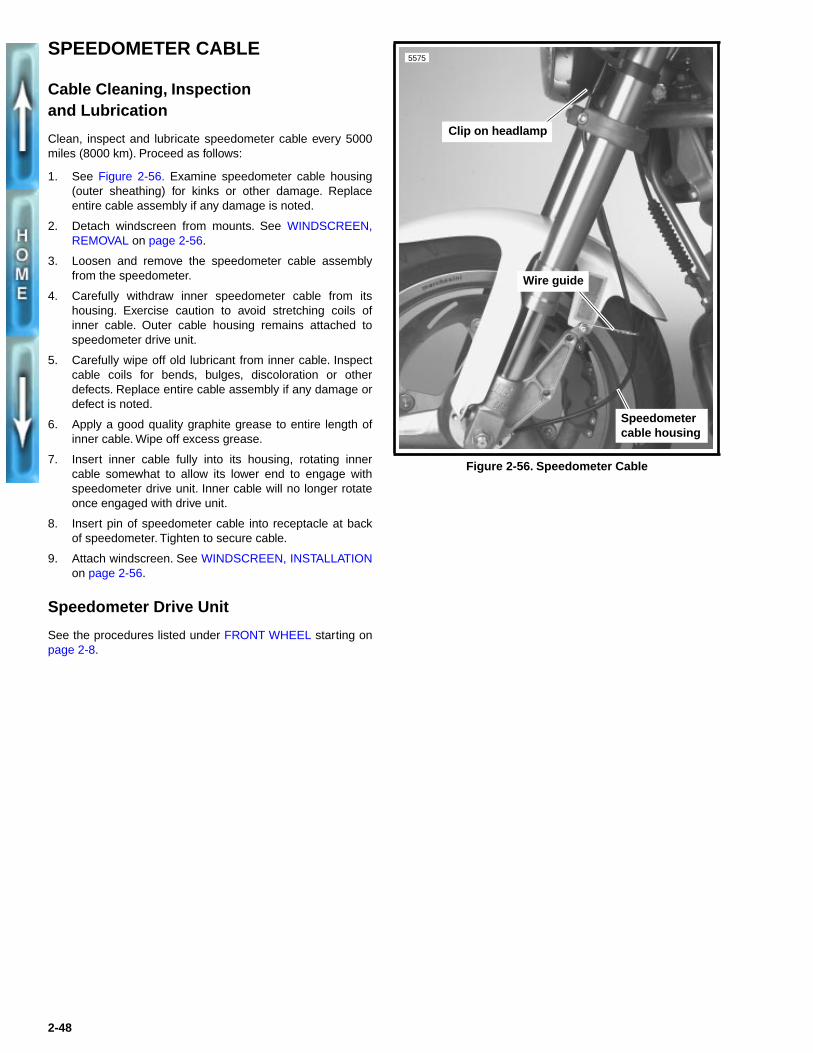
1. See Figure 2-56. Examine speedometer cable housing(outer sheathing) for kinks or other damage. Replaceentire cable assembly if any damage is noted.
2. Detach windscreen from mounts. See WINDSCREEN,REMOVAL on page 2-56.
3. Loosen and remove the speedometer cable assemblyfrom the speedometer.
4. Carefully withdraw inner speedometer cable from itshousing. Exercise caution to avoid stretching coils ofinner cable. Outer cable housing remains attached tospeedometer drive unit.
5. Carefully wipe off old lubricant from inner cable. Inspectcable coils for bends, bulges, discoloration or otherdefects. Replace entire cable assembly if any damage ordefect is noted.
6. Apply a good quality graphite grease to entire length ofinner cable. Wipe off excess grease.
7. Insert inner cable fully into its housing, rotating innercable somewhat to allow its lower end to engage withspeedometer drive unit. Inner cable will no longer rotateonce engaged with drive unit.
8. Insert pin of speedometer cable into receptacle at backof speedometer. Tighten to secure cable.
9. Attach windscreen. See WINDSCREEN, INSTALLATIONon page 2-56.
Speedometer Drive Unit
See the procedures listed under FRONT WHEEL starting onpage 2-8.
Figure 2-56. Speedometer Cable
Clip on headlamp
5575
Speedometer cable housing
Wire guide
2-48

HANDLEBAR
REMOVAL1. Remove front brake master cylinder. See FRONT
BRAKE MASTER CYLINDER, REMOVAL on page 2-19.
2. Remove left and right handlebar switch housings. SeeHANDLEBAR SWITCHES in Section 7.
3. Cut left handlebar grip and remove.
4. Remove instrument support. See SPEEDOMETER ANDTACHOMETER on page 2-46.
5. Loosen four screws (1) on upper handlebar clamp (2).
6. Move handlebar towards the air cleaner to increase clutchcable freeplay. Remove clutch control. See CLUTCHCONTROL, REMOVAL/DISASSEMBLY on page 2-44.
7. Remove four screws (1), upper handlebar clamp (2) andhandlebars (3).
8. Remove four bolts (8), lockwashers (7) and washers (6)to detach lower handlebar clamps (4, 5) from upper tripleclamp.
INSTALLATION1. Install lower handlebar clamps (4, 5) with four bolts (8),
lockwashers (7) and washers (6). Tighten to 30-33 ft-lbs(40.7-44.7 Nm).
2. Install clutch control. See CLUTCH CONTROL, ASSEM-BLY/INSTALLATION on page 2-45.
3. Install handlebar (3) using upper handlebar clamp (2)and four screws (1). Tighten screws to 10-12 ft-lbs (13.6-16.2 Nm).
4. Install instrument support. See SPEEDOMETER ANDTACHOMETER on page 2-46.
5. Install left and right handlebar switch housings. SeeHANDLEBAR SWITCHES in Section 7.
6. Install a new left handgrip.
a. Clean end of handlebar with M600.
b. Place LOCTITE 411 ADHESIVE around inside ofgrip.
c. Push grip onto handlebar end. Twist grip on bar untilend touches left switchgear housing.
d. Wipe off excess adhesive with a rag.
7. Install front brake master cylinder. See FRONT BRAKEMASTER CYLINDER, INSTALLATION on page 2-19.
Figure 2-57. Handlebars
b0220x2x
1
2
45
3
8
67
1. Screw (4)2. Upper handlebar
clamp3. Handlebar4. Lower right handlebar
clamp
5. Lower left handlebar clamp
6. Washer (4)7. Lockwasher (4)8. Bolt (4)
2-49

EXHAUST SYSTEM
REMOVAL/DISASSEMBLY
Muffler
1. See Figure 2-58. Remove bolts (2), locknuts (9) andwashers (6) from rear muffler supports (19).
2. Remove bolt (3) and locknut (9) from muffler support (15).
3. Loosen muffler clamp (14).
4. Loosen screw (1) on header tiebar (26).
5. Remove muffler (13) and muffler clamp. Discard clamp.
6. Remove muffler/header supports (15, 19) as follows:
a. Remove bolts (4), locknuts (9) and washers (21).
b. Remove rear muffler mounts (24) and mount spac-ers (20).
c. Remove bolts (5), locknuts (10) and washers (7).
d. Remove muffler support (15). Remove front mufflermounts (25) and mount spacer.
Exhaust Header
1. See Figure 2-58. Remove muffler as described above.
2. Remove screw (1), locknut (11) and washers (27) fromheader tiebar (26).
3. Using a SNAP-ON SWIVEL SOCKET (Part No.PFSX916), remove nuts (8) from front and rear cylinderhead exhaust studs.
4. Remove exhaust header clamps (18), exhaust clampretaining rings (17) and exhaust port gaskets (16).
5. Remove exhaust header (12).
6. Remove heat shield clamps (23) and heat shield (22)from exhaust header.
ASSEMBLY/INSTALLATION
Muffler
1. See Figure 2-58. If removed, install exhaust header (12).
2. If removed, install muffler/header supports (15, 19).
a. Hold rear muffler mounts (24), mount spacers (20)and muffler supports (19) in place. Fasten with bolts(4), locknuts (9), washers (21). Tighten to 12-15 ft-lbs (16.3-20.3 Nm).
b. Fasten muffler support (15) to crankcase with bolts(5), washers (7) and locknuts (10). Tighten to 30-33ft-lbs (40.7-44.7 Nm).
c. Install front muffler mounts (25) and mount spacer.
3. Coat inside of muffler inlet with PERMATEX ULTRA-COPPER HIGH TEMP RTV SILICON GASKET material.
4. Place a new muffler clamp (14) over slotted end of muf-fler. Place muffler and clamp on end of exhaust header.Loosely tighten clamp.
NOTE
If necessary, use a fiber hammer to fit muffler on header.
5. Install bolt (3) and locknut (9). Tighten to 22-25 ft-lbs(29.8-33.9 Nm).
1WARNING
Before tightening muffler hardware, position muffler toprovide adequate clearance from rear shock absorberand side stand spring post. Failure to provide adequateclearance may cause personal injury during motorcycleoperation.
6. Install rear mounting bolts (2), washers (6), and locknuts(9). Tighten to 22-25 ft-lbs (29.8-33.9 Nm).
7. Tighten muffler clamp (13) to 50-55 ft-lbs (67.8-74.6 Nm).
Exhaust Header
1. See Figure 2-58. Install new exhaust port gaskets (16),exhaust clamp retaining rings (17), exhaust headerclamps (18), and nuts (8). Loosely tighten nuts withSNAP-ON SWIVEL SOCKET (Part No. PFSX916).
2. Install screw (1) with washers (27) and locknut (11).Tighten to 5-7 ft-lbs (6.8-9.5 Nm).
3. Place a new muffler clamp (14) over slotted end of muf-fler. Place muffler and clamp on end of exhaust header(20). Loosely tighten clamp.
4. Tighten manifold nuts (8) to 6-8 ft-lbs (8.1-10.8 Nm).
5. Tighten muffler clamp (13) to 50-55 ft-lbs (67.8-74.6 Nm).
6. If removed, install heat shield (22) with heat shieldclamps (23).
2-50

Figure 2-58. Exhaust System
b0212x2x
9
21
24
20
19
421
9 6 26
7
7
10
5
15
2520
25
3
9
14
1617
188
11
2726
271
22
2312
13
1. Screw2. Bolt (2)3. Bolt4. Bolt (2)5. Bolt (2)6. Washer (4)7. Washer (5)8. Nut (4)9. Locknut (5)10. Locknut (2)
11. Locknut12. Exhaust header13. Muffler14. Muffler clamp15. Muffler support16. Exhaust port gasket (2)17. Exhaust clamp retaining
ring (2)18. Exhaust header clamp (2)19. Muffler support (2)
20. Mount spacer (3)21. Washer (4)22. Heat shield23. Heat shield clamp (2)24. Rear muffler mount (2)25. Front muffler mount (2)26. Header tiebar27. Washer (2)
2-51
FOOTRESTS
REMOVAL
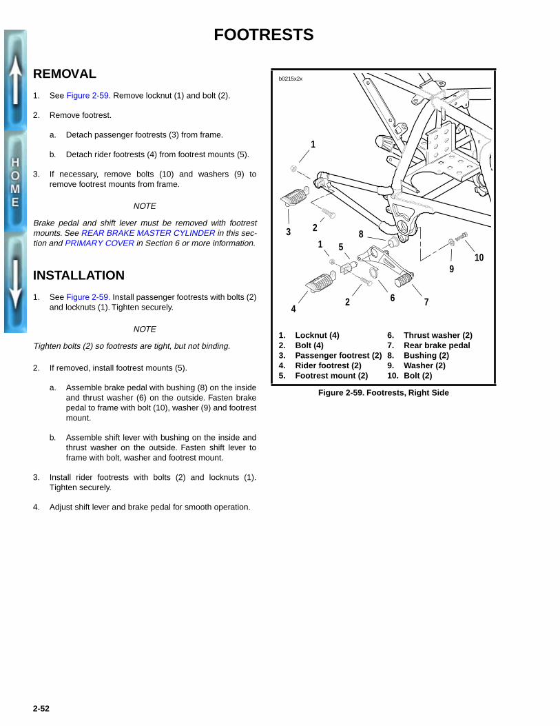
1. See Figure 2-59. Remove locknut (1) and bolt (2).
2. Remove footrest.
a. Detach passenger footrests (3) from frame.
b. Detach rider footrests (4) from footrest mounts (5).
3. If necessary, remove bolts (10) and washers (9) toremove footrest mounts from frame.
NOTE
Brake pedal and shift lever must be removed with footrestmounts. See REAR BRAKE MASTER CYLINDER in this sec-tion and PRIMARY COVER in Section 6 or more information.
INSTALLATION
1. See Figure 2-59. Install passenger footrests with bolts (2)and locknuts (1). Tighten securely.
NOTE
Tighten bolts (2) so footrests are tight, but not binding.
2. If removed, install footrest mounts (5).
a. Assemble brake pedal with bushing (8) on the insideand thrust washer (6) on the outside. Fasten brakepedal to frame with bolt (10), washer (9) and footrestmount.
b. Assemble shift lever with bushing on the inside andthrust washer on the outside. Fasten shift lever toframe with bolt, washer and footrest mount.
3. Install rider footrests with bolts (2) and locknuts (1).Tighten securely.
4. Adjust shift lever and brake pedal for smooth operation.
Figure 2-59. Footrests, Right Side
b0215x2x
1
1. Locknut (4)2. Bolt (4)3. Passenger footrest (2)4. Rider footrest (2)5. Footrest mount (2)
6. Thrust washer (2)7. Rear brake pedal8. Bushing (2)9. Washer (2)10. Bolt (2)
23
24
110
9
5
6 7
8
2-52
SPROCKET COVER
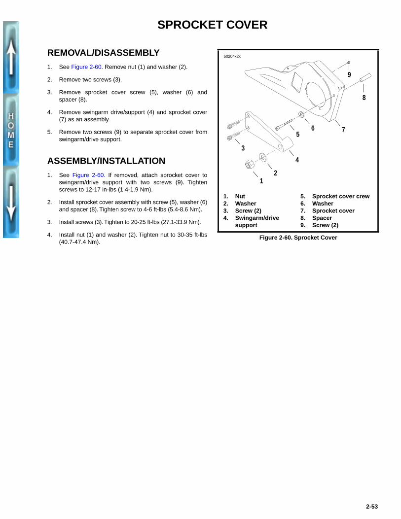
REMOVAL/DISASSEMBLY1. See Figure 2-60. Remove nut (1) and washer (2).
2. Remove two screws (3).
3. Remove sprocket cover screw (5), washer (6) andspacer (8).
4. Remove swingarm drive/support (4) and sprocket cover(7) as an assembly.
5. Remove two screws (9) to separate sprocket cover fromswingarm/drive support.
ASSEMBLY/INSTALLATION1. See Figure 2-60. If removed, attach sprocket cover to
swingarm/drive support with two screws (9). Tightenscrews to 12-17 in-lbs (1.4-1.9 Nm).
2. Install sprocket cover assembly with screw (5), washer (6)and spacer (8). Tighten screw to 4-6 ft-lbs (5.4-8.6 Nm).
3. Install screws (3). Tighten to 20-25 ft-lbs (27.1-33.9 Nm).
4. Install nut (1) and washer (2). Tighten nut to 30-35 ft-lbs(40.7-47.4 Nm).
Figure 2-60. Sprocket Cover
1. Nut2. Washer3. Screw (2)4. Swingarm/drive
support
5. Sprocket cover crew 6. Washer7. Sprocket cover8. Spacer9. Screw (2)
12
3
4
56 7
8
9
b0204x2x
2-53
FENDERS
REMOVAL/INSTALLATION
Front Fender
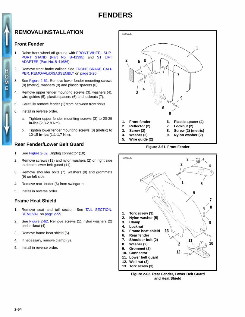
1. Raise front wheel off ground with FRONT WHEEL SUP-PORT STAND (Part No. B-41395) and S1 LIFTADAPTER (Part No. B-41686).
2. Remove front brake caliper. See FRONT BRAKE CALI-PER, REMOVAL/DISASSEMBLY on page 2-20.
3. See Figure 2-61. Remove lower fender mounting screws(8) (metric), washers (9) and plastic spacers (6).
4. Remove upper fender mounting screws (3), washers (4),wire guides (5), plastic spacers (6) and locknuts (7).
5. Carefully remove fender (1) from between front forks.
6. Install in reverse order.
a. Tighten upper fender mounting screws (3) to 20-25in-lbs (2.3-2.8 Nm).
b. Tighten lower fender mounting screws (8) (metric) to10-15 in-lbs (1.1-1.7 Nm).
Rear Fender/Lower Belt Guard
1. See Figure 2-62. Unplug connector (10)
2. Remove screws (13) and nylon washers (2) on right sideto detach lower belt guard (11).
3. Remove shoulder bolts (7), washers (8) and grommets(9) on left side.
4. Remove rear fender (6) from swingarm.
5. Install in reverse order.
Frame Heat Shield
1. Remove seat and tail section. See TAIL SECTION,REMOVAL on page 2-55.
2. See Figure 2-62. Remove screws (1), nylon washers (2)and locknut (4).
3. Remove frame heat shield (5).
4. If necessary, remove clamp (3).
5. Install in reverse order.
Figure 2-61. Front Fender
Figure 2-62. Rear Fender, Lower Belt Guardand Heat Shield
1. Front fender2. Reflector (2)3. Screw (2)4. Washer (2)5. Wire guide (2)
6. Plastic spacer (4)7. Locknut (2)8. Screw (2) (metric)9. Nylon washer (2)
b0216x2x
1
34
7
68
9
2 5 6
1. Torx screw (3)2. Nylon washer (5)3. Clamp4. Locknut5. Frame heat shield6. Rear fender7. Shoulder bolt (2)8. Washer (2)9. Grommet (2)10. Connector11. Lower belt guard12. Well nut (3)13. Torx screw (3)
b0218x2x
6
1
23
5
4
7
8
9
102
13
12
11
2-54
TAIL SECTION
REMOVAL
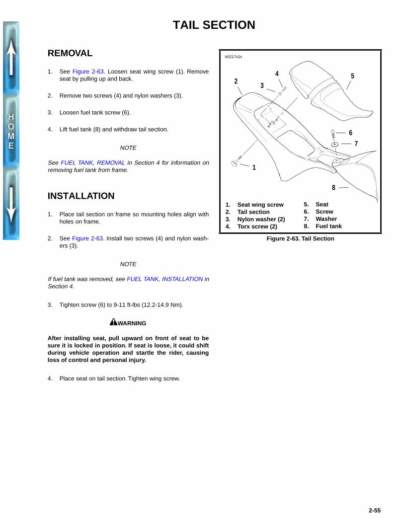
1. See Figure 2-63. Loosen seat wing screw (1). Removeseat by pulling up and back.
2. Remove two screws (4) and nylon washers (3).
3. Loosen fuel tank screw (6).
4. Lift fuel tank (8) and withdraw tail section.
NOTE
See FUEL TANK, REMOVAL in Section 4 for information onremoving fuel tank from frame.
INSTALLATION
1. Place tail section on frame so mounting holes align withholes on frame.
2. See Figure 2-63. Install two screws (4) and nylon wash-ers (3).
NOTE
If fuel tank was removed, see FUEL TANK, INSTALLATION inSection 4.
3. Tighten screw (6) to 9-11 ft-lbs (12.2-14.9 Nm).
1WARNING
After installing seat, pull upward on front of seat to besure it is locked in position. If seat is loose, it could shiftduring vehicle operation and startle the rider, causingloss of control and personal injury.
4. Place seat on tail section. Tighten wing screw.
Figure 2-63. Tail Section
b0217x2x
1. Seat wing screw 2. Tail section3. Nylon washer (2)4. Torx screw (2)
5. Seat6. Screw7. Washer8. Fuel tank
42 3
7
1
5
6
8
2-55

WINDSCREEN
REMOVAL1. See Figure 2-64. Remove two screws and nylon washers
on each side.
2. Detach windscreen from center bracket on tachometercover. Remove windscreen.
3. If necessary, remove the three windscreen brackets.
a. See Figure 2-65. Remove center windscreenbracket by removing nut on tachometer cover.
b. While holding headlamp, remove left and right head-lamp adjusting screws (metric). Slide windscreenbrackets from between headlamp housing andheadlamp brackets.
INSTALLATION1. If removed, install the three windscreen brackets.
a. See Figure 2-65. Install center bracket using nut.
b. Install left and right brackets between headlamphousing and headlamp brackets. Tighten headlampadjusting screws (metric) 6-8 ft-lbs (8.1-10.8 Nm).
2. Align windscreen on right, left and center brackets.Attach windscreen to center bracket velcro strip.
3. See Figure 2-64. Install two screws and nylon washerson each side.
Figure 2-64. Windscreen, Right Side
Figure 2-65. Windscreen Brackets
5724
Screws and nylon washers
5723
1
2 3
1. Center bracket with nut and velcro strip
2. Right bracket3. Left bracket
2-56
SEAT
REMOVAL
1. See Figure 2-66. Detach seat from frame by looseningthe wing screw underneath the tail section.
2. Remove seat by pulling up and back.
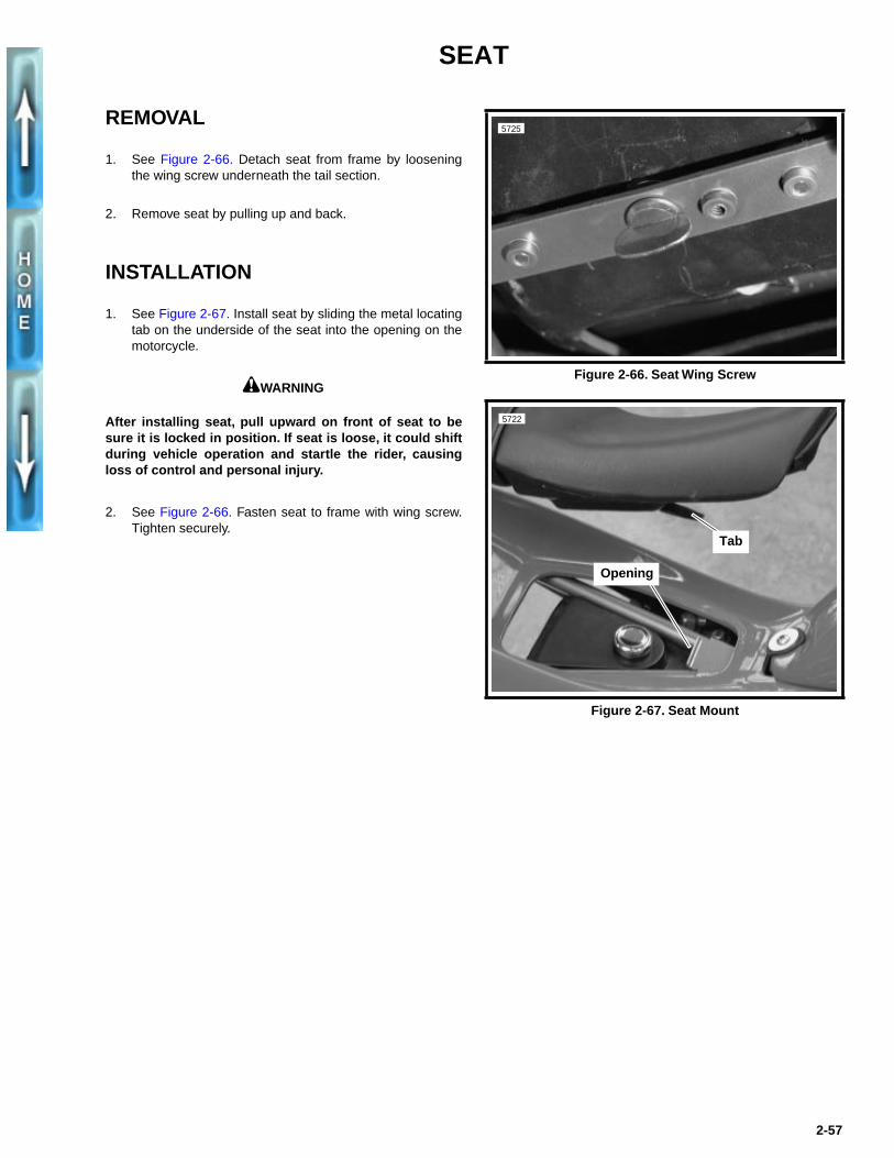
INSTALLATION
1. See Figure 2-67. Install seat by sliding the metal locatingtab on the underside of the seat into the opening on themotorcycle.
1WARNING
After installing seat, pull upward on front of seat to besure it is locked in position. If seat is loose, it could shiftduring vehicle operation and startle the rider, causingloss of control and personal injury.
2. See Figure 2-66. Fasten seat to frame with wing screw.Tighten securely.
Figure 2-66. Seat Wing Screw
Figure 2-67. Seat Mount
5725
5722
Tab
Opening
2-57

SIDE STAND
GENERAL The side stand is located on the left side of the motorcycle.The side stand swings outward to support the motorcycle forparking.
Test the side stand in the following manner. Without vehicleweight resting on it, side stand should move freely intoextended (down) and retracted (up) positions.
REMOVAL/DISASSEMBLY1. See Figure 2-68. Remove spring (6) from side stand and
spring pin (5).
2. Remove retaining clip (7) and pivot pin (8). Detach sidestand from frame.
3. Remove screw (2) and side stand dragger (1).
4. Remove bumper (3) from frame.
ASSEMBLY/INSTALLATION1. See Figure 2-68. Attach bumper (3) to frame.
2. Attach side stand dragger (1) to side stand with screw (2).
3. Install side stand using pivot pin (8) and retaining clip (7).
4. Connect spring (6) to side stand and spring pin (5).
1WARNING● If the side stand is not in the full forward position
when vehicle weight is rested on it, the vehicle couldfall over, possibly causing personal injury.
● Always park motorcycle on a level, firm surface.Vehicle weight could cause motorcycle to fall over,possibly causing personal injury.
● Be sure side stand is fully retracted before riding themotorcycle. If side stand is not fully retracted duringvehicle operation, it could contact the road surfacecausing a momentary disturbance before retracting.This momentary disturbance could distract the rider,possibly causing loss of vehicle control and per-sonal injury.
Figure 2-68. Side Stand
b0219x2x
1. Side stand dragger2. Screw3. Bumper4. Side stand
5. Spring pin6. Spring7. Retaining clip8. Pivot pin
12
4
3
8
7
56
2-58