front light diy for ngpc - jamma-nation-x. · pdf file1 gameboy advanced sp, model ags-001...
TRANSCRIPT
DIY Instructions For NGPC Front Light Installationusing the Gameboy Advanced SP Front Light
Tools you will need:Phillips Screwdriver
Flat head Screwdriver
Tri-wing Screwdriver
Exacto Knife
Soldering Iron (Adjustable wattage recommended)
Solder (Silver core recommended)
Wire Cutter (Snips even better)
1 - SP Front Light
1 - 3mm LED (optional)
1 - 47 ohm 1/4 watt resistor
5” of Blue Kynar Wrapping Wire(available at RS)
5” of Red Kynar Wrapping Wire(You can also use any 30 awg wire)
Electric tape
1 Gameboy Advanced SP, model AGS-001 (Front Light Model)
Ok so first thing first you will need an SP 1st version as it is front lit andthe SP2 are back lit and will not work.
1. Opening the SP
There is 5 Triwing screws that hold it together. To open the SP
you will need to remove the 5 rubber grommets. You can do this
by using an exacto knife and sliding the knife around the
grommet first them sticking it under the grommet and popping it
out. It is held on by a soft adhesive. Make sure you remove the
remnants of the adhesive prior to removing the screw as the
adhesive will prevent the triwing bit from biting.

This is where the screws are located:
After you remove them it should look like this:
The next step is to remove the backing, just gently pry it off the front
half and it should look like this:

Inside you will see this ribbon, to remove the ribbon you will need to
desolder the 2 points that are circled. For this procedure it is easier to
use a lower wattage setting to keep the 2 points intact after removing
the ribbon. These 2 solder points are the power and ground for the
front light.

After you desolder the 2 points separate it from the other ribbon, it is
imperative that you do not tear this ribbon, if you do you will have to
find another way to solder the power and ground to the front light.

To remove the LCD from the housing just simply pry it out, you will see
very small tabs barely holding it in, just pop it out. Do not stick whatever
your using too far in (1/8”+) as it will scratch the front light screen.
After you remove the LCD you will then need to separate the front light housing
from the front plastic screen. This is simply done by gently gliding your exacto
knife between the housing and the front plastic screen. Whatever you do, DO NOT
touch the front light screen as the oil from your skin will stain the front light screen
and if you try to wipe it off it will scratch the front light screen and also transfer lint
that you will not be able to remove. The screen is very sensitive.
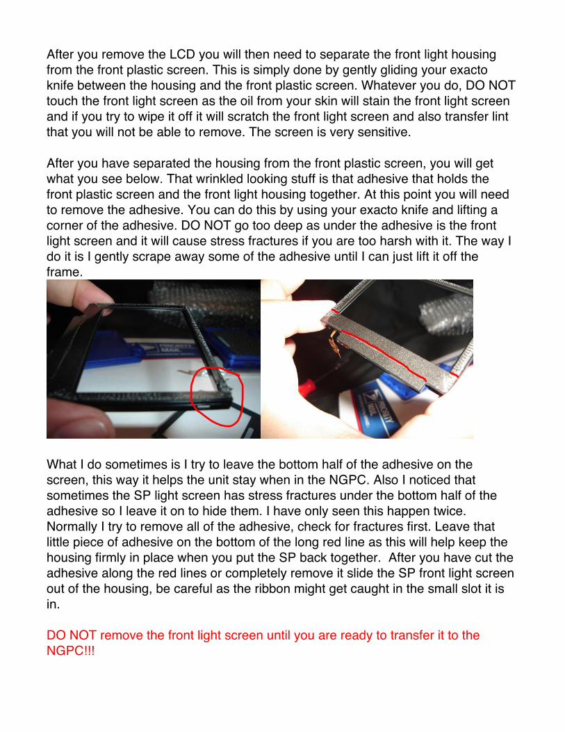
After you have separated the housing from the front plastic screen, you will get
what you see below. That wrinkled looking stuff is that adhesive that holds the
front plastic screen and the front light housing together. At this point you will need
to remove the adhesive. You can do this by using your exacto knife and lifting a
corner of the adhesive. DO NOT go too deep as under the adhesive is the front
light screen and it will cause stress fractures if you are too harsh with it. The way I
do it is I gently scrape away some of the adhesive until I can just lift it off the
frame.
What I do sometimes is I try to leave the bottom half of the adhesive on the
screen, this way it helps the unit stay when in the NGPC. Also I noticed that
sometimes the SP light screen has stress fractures under the bottom half of the
adhesive so I leave it on to hide them. I have only seen this happen twice.
Normally I try to remove all of the adhesive, check for fractures first. Leave that
little piece of adhesive on the bottom of the long red line as this will help keep the
housing firmly in place when you put the SP back together. After you have cut the
adhesive along the red lines or completely remove it slide the SP front light screen
out of the housing, be careful as the ribbon might get caught in the small slot it is
in.
DO NOT remove the front light screen until you are ready to transfer it to the
NGPC!!!

Now go to your NGPC and turn it over to it!s back side. There are 5 phillips screws
and 1 triwing screw holding everything together, hopefully common sense will tell
you the locations after looking at the picture below on the left. In the picture on the
right this is what your NGPC will look like once you get the back cover off, there
are 3 red circles which supposedly show the locations of the screws holding down
the PCB. I say supposedly because for some reason SNK sometimes has 1, 2 or
3 screws holding them down, I find it weird when some units only have 1 screw
and others 2 or 3. These are Philips screws. Just remove them.
Now you will need to desolder the speaker wiring which are located on the right
side of the PCB. Just desolder them and move them out of the way. Next thing
you need to do is flip your NGPC over and remove the joystick. This is done by
using a flat object to pry it off. I do not use an exacto to do this, it is only for
reference. I usually use the flat end of a nail clipper. Insert it from the side and pry
it upward so it will slide off, DO NOT force it just be gentle it will slide off.

It will look like this if you did it right.
Now with the NGPC screen facing you, you will have to release the LCD ribbon so
you can separate the PCB and the front half of the NGPC. This is done in usual
ribbon fashion by simply sliding the left and right sides down to unlock it and then
gently pull the LCD ribbon down and out.

You will now see the front of the PCB which is white. Remove the 4 orange
sponges from the board.
Now you will need to snip off the 4 plastic grommets, these are made to look like
they!re holding the cartridge slot but since the slot is soldered to the PCB you do
not need these. These need to be removed so the front light screen has more
space to fit as it is already a tight fit without it. It might be easier to snip them from
the back side of the PCB as you may cut a trace from the front side(white).

Back Side
This is also the perfect time to change your Power LED if you want. Simply
remove the old one and put the new one in. Remember that the longer lead is the
positive and that positive flows to negative( I>), when soldering the new LED in
place make sure to raise the LED about 1/8” off the PCB.

The next step takes the utmost care as you can possibly damage your NGPC
LCD. At the spot circled insert your flat head screwdriver under the LCD about
1/8”. Then gently twist the screwdriver to release the LCD from the adhesive, you
might hear a pop. If you hear a crack then you might have damaged you LCD,
check the front if it looks cracked, if not then that was a pop. Once it has released
go around the edges of the LCD to get it out.

Now with the LCD removed you will need to make 3 slices from the top of the
plastic to the base at the 3 locations shown below. This is done due to the fact that
the SP light screen is wider than the housing. With this being said, if you have a
clear NGPC you can either do it this way or you can cut the SP light screen to fit
the housing but keep in mind that if you cut the light screen that it will show ghost
lines on the screen since the light reflects differently after you cut it. I only say this
for the clear units since you will be able to see the wider light screen through the
housing of the NGPC, if that is fine with you then no problem just keep going. But
if you don!t want the wider screen to be seen then I would recommend cutting the
screen to fit the housing. I do have to warn you that it is not easy to cut the screen
and not have anything adverse happen such as lint, scratches and what not.

Next you will need to score the left and right walls of the housing. This is done by
running your exacto knife along the bottom of the wall from side to side with
moderate pressure. You will need to do this about 3 times. Try to score it at the
very bottom of the wall as possible as we will be removing these walls to make
way for the front light screen.
Once you have finished scoring the walls you can now remove them using a pair
of pliers or wire cutters. Simply grab the plastic wall from one end and twist it until
it separates from the unit, keep moving down the wall and repeating until the wall
is completely removed. Repeat for the right wall. DO NOT remove the bottom wall
as that will hold the LCD and the front light screen in place.

I increased the brightness of this picture so you can see how it should look after
you remove the left and right walls. Make sure that there are no peaks in the
remnants that are higher than the LCD adhesive. If there is the you will have to
flatten them by shaving some plastic off. If there are peaks it will crack the front
light screen when the unit is tightened.

Before you move on, make sure there is no dust or fingerprints on the inside of the
NGPC front plastic screen.
Now insert the SP light screen into the NGPC housing. It should look like the
picture below. When placing the screen into the housing align the left side with the
notch that is noted in red, make sure you push the screen downward towards the
bottom wall before pressing it to make the adhesive stick. If done properly the
front light screen will be between the button housing and the joystick housing.
Also make sure the front light ribbon is facing you and not on the underside of the
front light.

After your front light is in place you will need to place the NGPC LCD back into the
housing. YOU WILL need to align the LCD as you no longer have the left and right
walls to align it for you. It is simple to do. The upper right wall is still there so you
can align it with that. You can also still see where the walls were so don!t freak
out. Once you align the LCD you can secure it on the left and right sides with
electric tape.
Now at this point you will need to wire the power and ground for the front light. On
the 2 points of the ribbon solder the 5” Red Kynar wire to the left point and the
Blue to the Right. Please double check the polarity after you solder the wires on.
You can check them with the CR2032 battery from the NGPC, just keep note of
which is + and which is -. After you have soldered them to the ribbon, place some
electric tape on the ribbon to cover the front and back. Bend the ribbon down so it
is not on the back of the LCD and run the wires along the bottom of the NGPC and
place small strips of electric tape to hold them in place.

After you have routed your wires to come out of the side of your NGPC, you will
need to reconnect the LCD ribbon which is done the opposite way by making sure
the plastic connector is unlocked(down position) then inserting the ribbon and
pushing the plastic connector back to the locked (up) position on both sides.
Reinstall the 1-3 screws that hold the PCB and also put your joystick back on.
Resolder the speaker wires back on.
Now with the backside of the PCB facing you:
On the positive wire you will need to solder the 47 ohm resistor on and then solder
the other end of the resistor to capacitor 20 on the PCB which is labeled as C20,
for slimline NGPCs it is the same capacitor but it is located just above the
cartridge slot.
For the ground you can solder it to any round you choose but I always use the
spot right below the port which you see in the picture.

Now place the back cover back on your NGPC and screw it on BUT do not make it
too tight, once you feel resistance turn another 1/8 turn. Anything tighter may
cause your front plastic screen to start popping out from the bottom right corner. If
this does happen you can resecure it using automotive emblem glue. This glue
works good as it is strong but does not give off fumes like super glue and cause
fingerprints to appear.
Turn your unit on and it should look like this:
Good luck and take your time and have fun when you’re done.
Xian Xi aka SupremeJudge