front loader “mtz” - belarus b+ 3f... · 1 front loader “mtz” model kr-34 technical...
TRANSCRIPT

1
FRONT LOADER “MTZ”
Model KR-34
TECHNICAL SPECIFICATION
AND OPERATION MANUAL
Variant B+3F
Head Office: 36 Renaissance Crt., Thornhill, Ontario. L4J 7W4 Canada
Warehouse: 2682 Highway 34, Hawkesbury, Ontario. K6A 2R2 Canada
Tel: 1-855-2GO-4MTZ (1-855-246-4689) Fax: 1-647 933-9066 E-mail: [email protected] Web: www.mtzequipment.com
2
Contents:
GENERAL CONDITIONS 4
Warning symbols 4
3 Basic Technical Specification 11
4 Assembly Set 11
6 Control set for additional Distributor by “Joystick” 12
6.1. Distributor 12
6.2. Joystick Handle 13
6.3. 3-rd Function Control Set 13
7. Preparation of MTZ tractor to operations with KR-34 Loader 14
7.1. Mounting of connecting frame. (Fig.7) 14
7.2. Connection to the tractor hydraulic system.( Control set “B” ) 14
7.2.1. Alternation ( rearrangement of tractor hydraulic system) 14
7.2.2. Mounting and connection of the hydraulic distributor 14
8.1 Frontal Loader Operation Control 15
8.2. Connecting of Front Loader to the tractor 16
8.3. Disconnecting of Front Loader from the tractor 17
8.4. Connecting and change of implements 17
8.5. Connection and change of hydraulically operated implements
as units of the “3-rd Function Set”
18
9. Safety Measures 18
10. PROHIBITED 19
11. Obligatory 19
12. Daily and periodic maintenance 20
13. Corrosion Proofing and Storage 20
14.
15
Loader Operation and Maintenance. Troubleshooting.
20
21
16. Drawings and scheme. 23
3
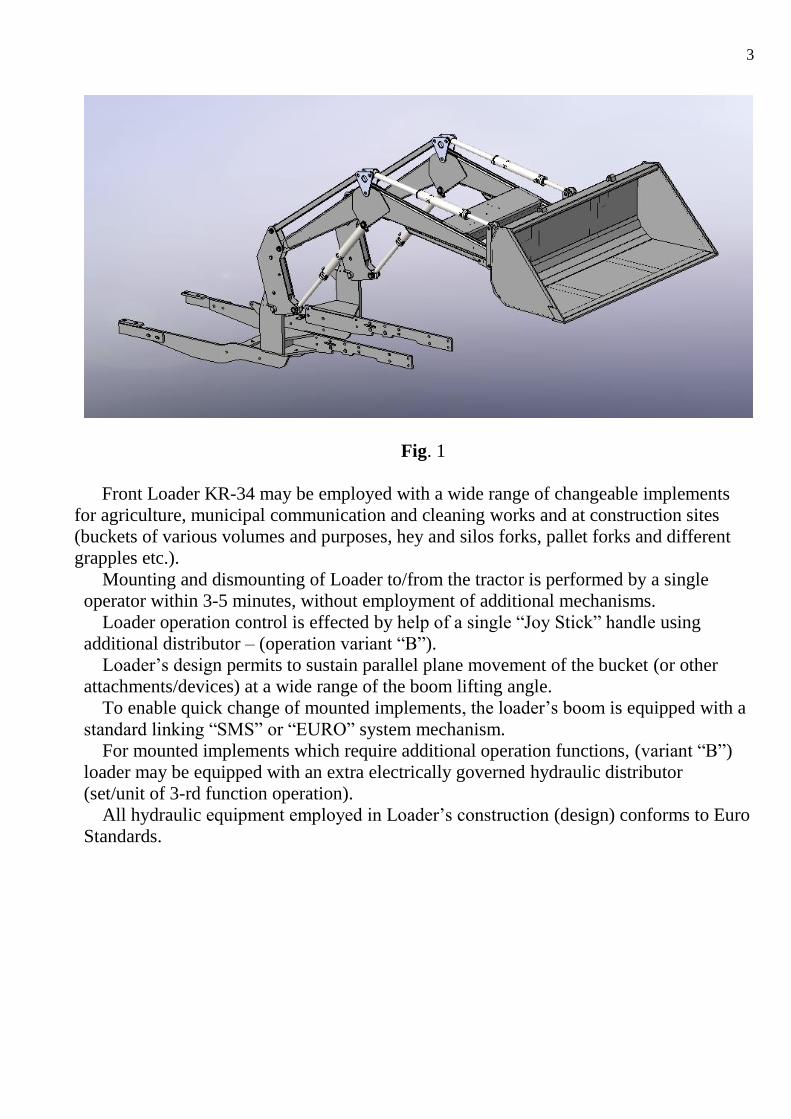
Fig. 1
Front Loader KR-34 may be employed with a wide range of changeable implements
for agriculture, municipal communication and cleaning works and at construction sites
(buckets of various volumes and purposes, hey and silos forks, pallet forks and different
grapples etc.).
Mounting and dismounting of Loader to/from the tractor is performed by a single
operator within 3-5 minutes, without employment of additional mechanisms.
Loader operation control is effected by help of a single “Joy Stick” handle using
additional distributor – (operation variant “B”).
Loader’s design permits to sustain parallel plane movement of the bucket (or other
attachments/devices) at a wide range of the boom lifting angle.
To enable quick change of mounted implements, the loader’s boom is equipped with a
standard linking “SMS” or “EURO” system mechanism.
For mounted implements which require additional operation functions, (variant “B”)
loader may be equipped with an extra electrically governed hydraulic distributor
(set/unit of 3-rd function operation).
All hydraulic equipment employed in Loader’s construction (design) conforms to Euro
Standards.
4
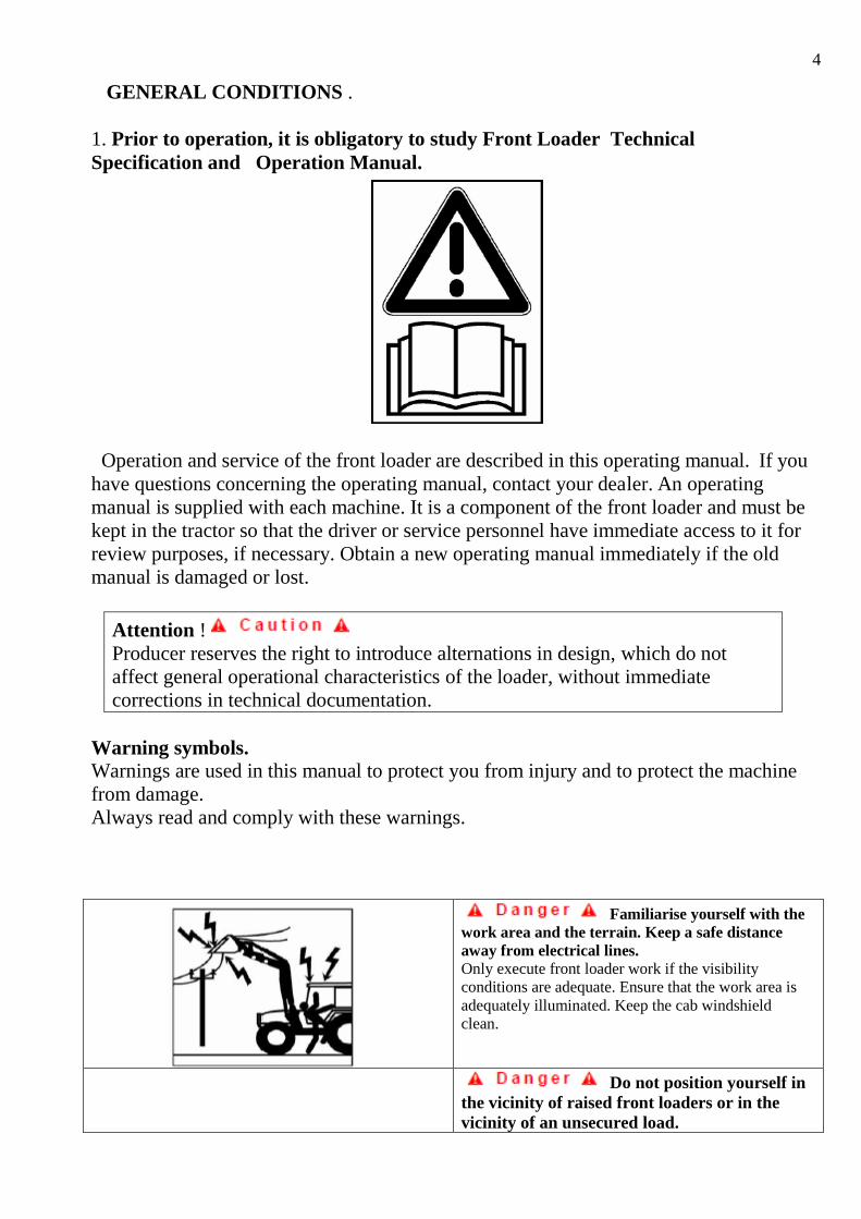
GENERAL CONDITIONS .
1. Prior to operation, it is obligatory to study Front Loader Technical
Specification and Operation Manual.
Operation and service of the front loader are described in this operating manual. If you
have questions concerning the operating manual, contact your dealer. An operating
manual is supplied with each machine. It is a component of the front loader and must be
kept in the tractor so that the driver or service personnel have immediate access to it for
review purposes, if necessary. Obtain a new operating manual immediately if the old
manual is damaged or lost.
Attention !
Producer reserves the right to introduce alternations in design, which do not
affect general operational characteristics of the loader, without immediate
corrections in technical documentation.
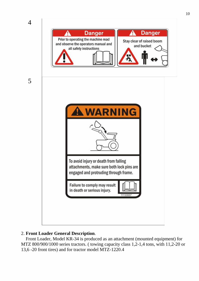
Warning symbols.
Warnings are used in this manual to protect you from injury and to protect the machine
from damage.
Always read and comply with these warnings.
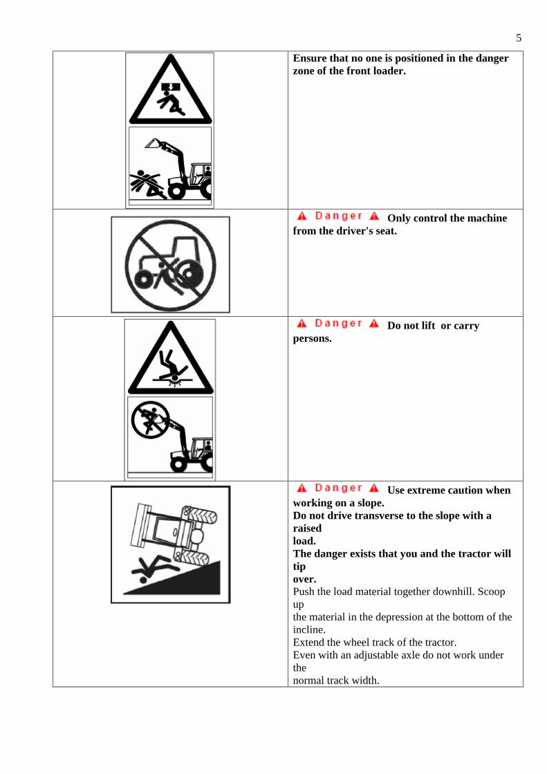
Familiarise yourself with the
work area and the terrain. Keep a safe distance
away from electrical lines.
Only execute front loader work if the visibility
conditions are adequate. Ensure that the work area is
adequately illuminated. Keep the cab windshield
clean.
Do not position yourself in
the vicinity of raised front loaders or in the
vicinity of an unsecured load.
5
Ensure that no one is positioned in the danger
zone of the front loader.
Only control the machine
from the driver's seat.
Do not lift or carry
persons.
Use extreme caution when
working on a slope.
Do not drive transverse to the slope with a
raised
load.
The danger exists that you and the tractor will
tip
over.
Push the load material together downhill. Scoop
up
the material in the depression at the bottom of the
incline.
Extend the wheel track of the tractor.
Even with an adjustable axle do not work under
the
normal track width.
6
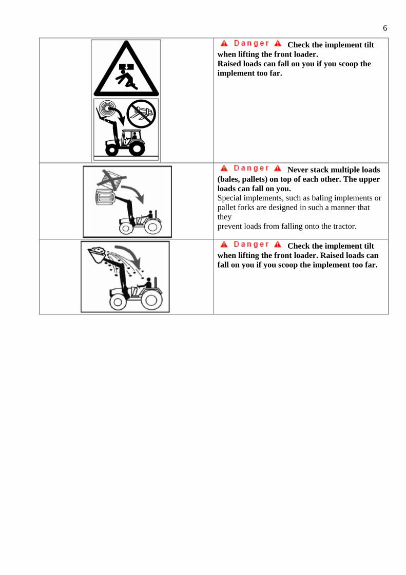
Check the implement tilt
when lifting the front loader.
Raised loads can fall on you if you scoop the
implement too far.
Never stack multiple loads
(bales, pallets) on top of each other. The upper
loads can fall on you.
Special implements, such as baling implements or
pallet forks are designed in such a manner that
they
prevent loads from falling onto the tractor.
Check the implement tilt
when lifting the front loader. Raised loads can
fall on you if you scoop the implement too far.
7
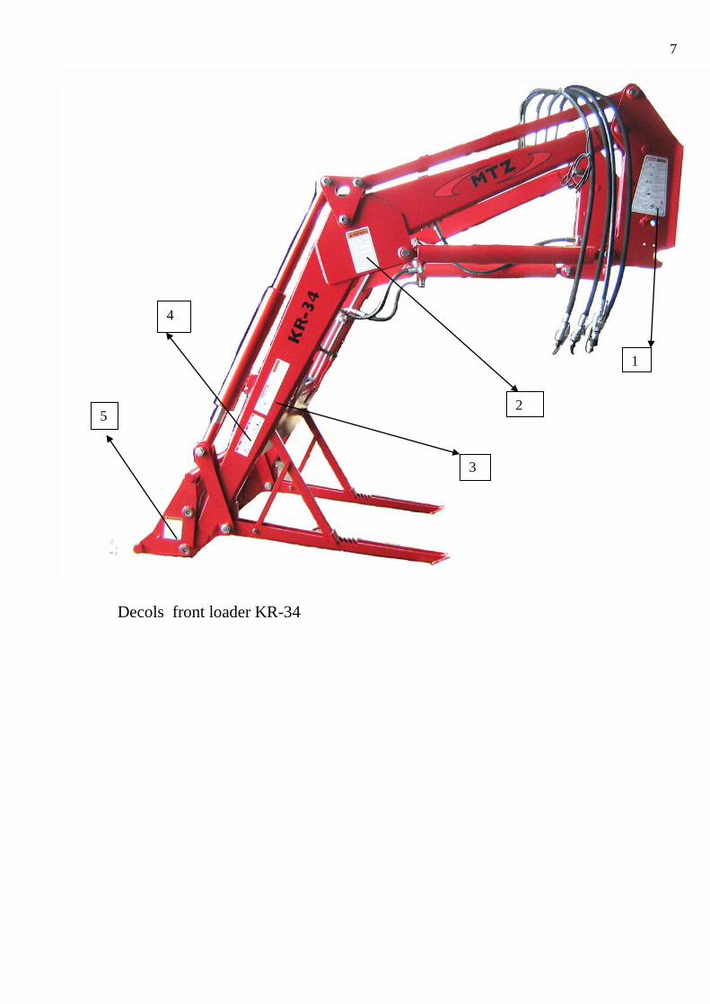
Decols front loader KR-34
1
2
3
4
5
8
1
9
2
3
10
4
5
2. Front Loader General Description.
Front Loader, Model KR-34 is produced as an attachment (mounted equipment) for
MTZ 800/900/1000 series tractors. ( towing capacity class 1,2-1,4 tons, with 11,2-20 or
13,6 -20 front tires) and for tractor model MTZ-1220.4
11
Attention! When operations with loads, exceeding 800 kg.
counterweight, not less than 800 kg. must be attached to the rear tractor linkage.
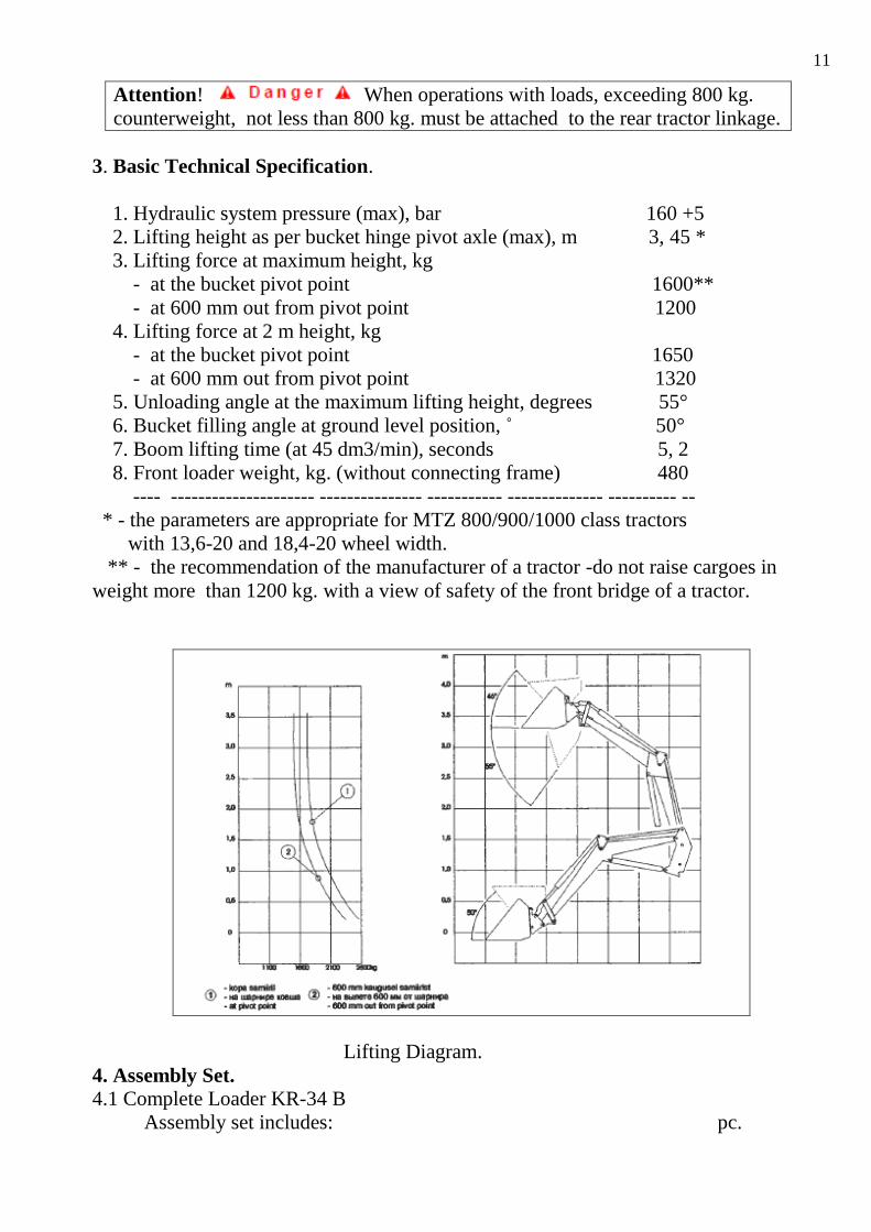
3. Basic Technical Specification.
1. Hydraulic system pressure (max), bar 160 +5
2. Lifting height as per bucket hinge pivot axle (max), m 3, 45 *
3. Lifting force at maximum height, kg
- at the bucket pivot point 1600**
- at 600 mm out from pivot point 1200
4. Lifting force at 2 m height, kg
- at the bucket pivot point 1650
- at 600 mm out from pivot point 1320
5. Unloading angle at the maximum lifting height, degrees 55°
6. Bucket filling angle at ground level position, ˚ 50°
7. Boom lifting time (at 45 dm3/min), seconds 5, 2
8. Front loader weight, kg. (without connecting frame) 480
---- --------------------- --------------- ----------- -------------- ---------- --
* - the parameters are appropriate for MTZ 800/900/1000 class tractors
with 13,6-20 and 18,4-20 wheel width.
** - the recommendation of the manufacturer of a tractor -do not raise cargoes in
weight more than 1200 kg. with a view of safety of the front bridge of a tractor.
Lifting Diagram.
4. Assembly Set.
4.1 Complete Loader KR-34 B
Assembly set includes: pc.
12
Loader 3405.16 1
Set of connection frame and fixings 1
Connection set and Operation control set ”B”(from additional
distributor by a single “ Joystick” 1
Technical Specification and Operation Manual 1
5. Additionally “by order” :
5.1. Set for the 3-rd function control.
5.2. Shock absorbing valves for “B” control set.
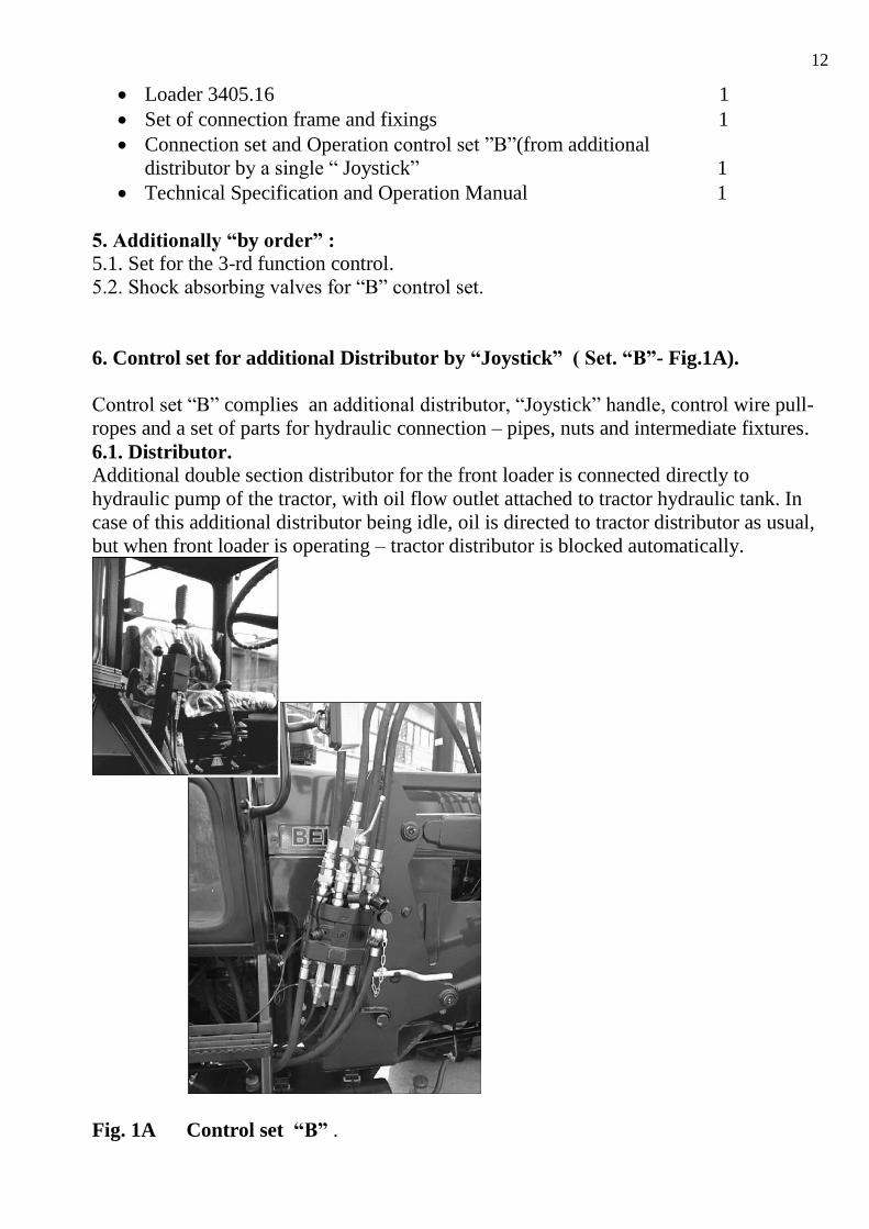
6. Control set for additional Distributor by “Joystick” ( Set. “B”- Fig.1A).
Control set “B” complies an additional distributor, “Joystick” handle, control wire pull-
ropes and a set of parts for hydraulic connection – pipes, nuts and intermediate fixtures.
6.1. Distributor.
Additional double section distributor for the front loader is connected directly to
hydraulic pump of the tractor, with oil flow outlet attached to tractor hydraulic tank. In
case of this additional distributor being idle, oil is directed to tractor distributor as usual,
but when front loader is operating – tractor distributor is blocked automatically.
Fig. 1A Control set “B” .
13
When front loader is not operating – tractor distributor is functioning without any
limitations. Distributor section which governs bucket turning movements has two
unfixed working positions with a forced return into neutral position.
Section which controls boom′s lift and lowering, has an additional “flowing”
position.
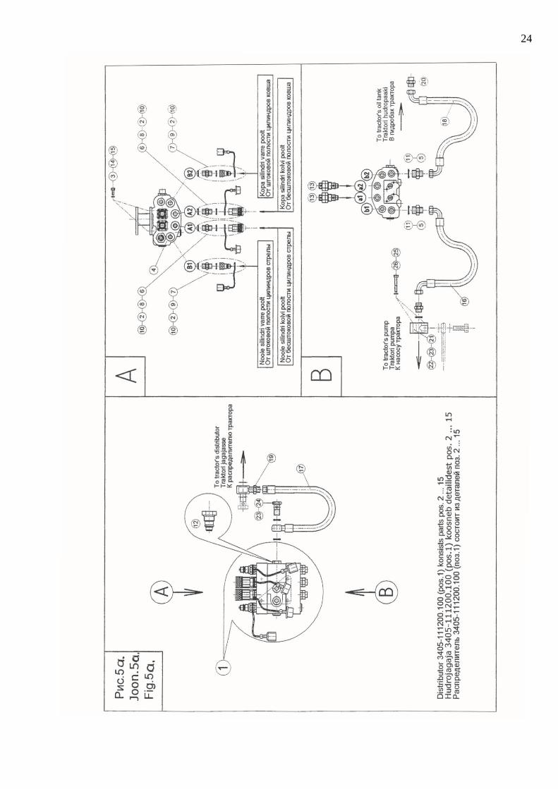
To avoid hydraulic system overload – distributor is equipped with inside security
valve. In order to eliminate extra high overload impacts, two additional build-in
antishok valves can be ordered to distributor set separately. ( p.13 Fig. 5a)
Attention! Loader Hydraulic system is connected to the additional
distributorby 4 flexible hydraulic pipes by help of quick acting clutches.
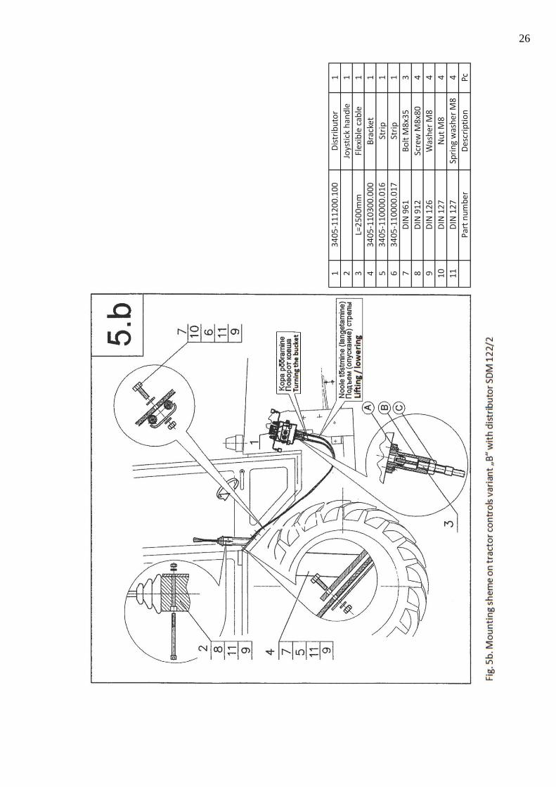
6.2 Joystick Handle.
Additional distributor is controlled by a single “Joystick” type handle. Joystick is
connected by flexible wire pull-ropes (Bowden cables) with distributor slide-valves.
(Fig.5b.)
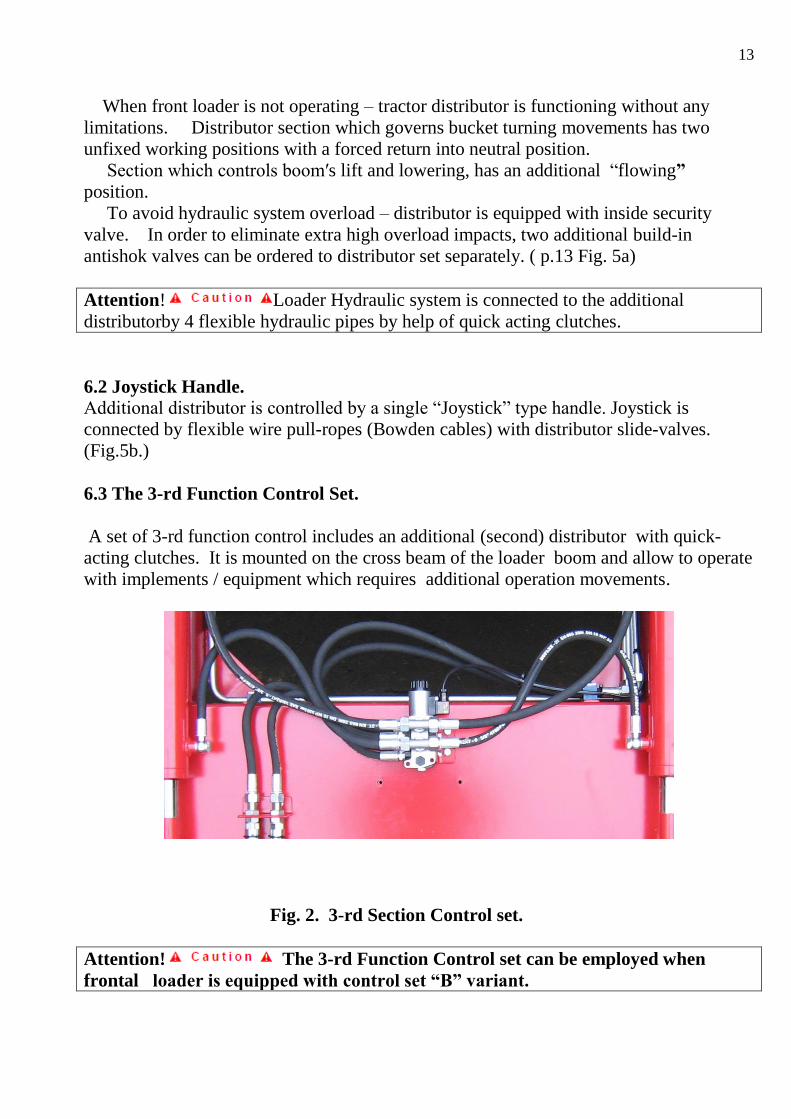
6.3 The 3-rd Function Control Set.
A set of 3-rd function control includes an additional (second) distributor with quick-
acting clutches. It is mounted on the cross beam of the loader boom and allow to operate
with implements / equipment which requires additional operation movements.
Fig. 2. 3-rd Section Control set.
Attention! The 3-rd Function Control set can be employed when
frontal loader is equipped with control set “B” variant.
14
7. Preparation of “Belarus” MTZ tractor to operations with KR-34 Loader.
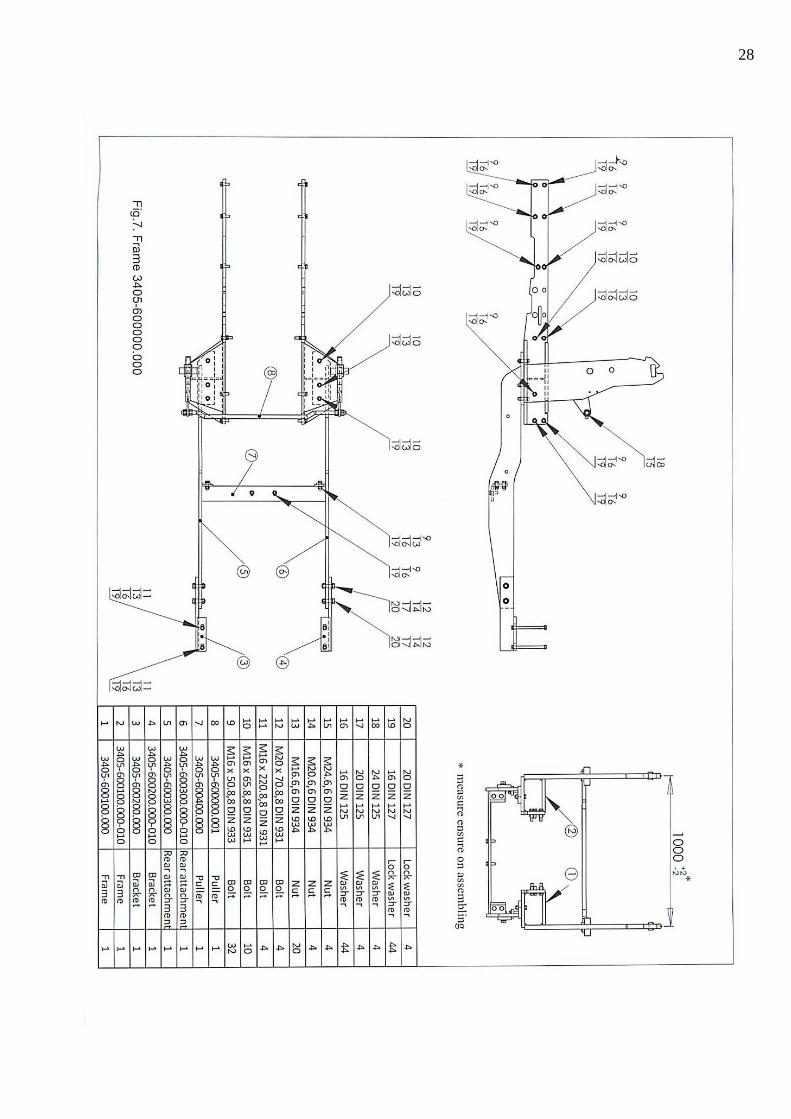
7.1 Mounting of connecting frame. (Fig.7)
Forward parts (right and left) of connecting frame (pos. 1and 2) are attached to the
tractor side rails, and back frame beams are fixed on tractor back axle metal hose/collar
by help of bolts.
Vertical posts of semi-frames are connected with each other by puller and rear
attachment are fixed by puller (7) and attached to the body of tractor’s gear box. The
distance between posts is adjusted according ( Fig.1) by means of puller 8.
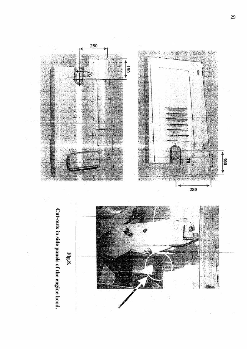
Attention ! When required, cut-outs to be made in side panels of the
engine hood as shown on Fig. 8
7.2 Connection to the tractor hydraulic system. ( Control set “B” )
7.2.1 Alternation (rearrangement of tractor hydraulic system:
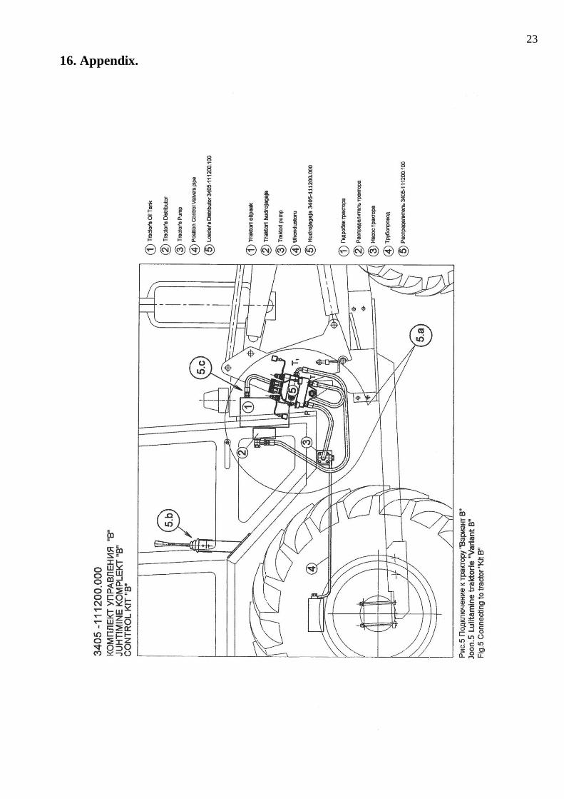
Disconnect the pipeline of the power position regulator ( Pos.4, Fig. 5) from the
flange of the tractor pump (pos.3).
Dismount the pressure pipe, which connects the pump with tractor distributor.
Attach connector (19,Fig.5a) to the distributor (2, Fig.5a).
Assemble/adjust the plate (21, Fig.5a) together with connector (22) and washer
(23) on to the pump.
Attention! Pressure O-ring from the pressure pipe must be used when assembling the
plate and the pump.
Connect Power position regulator pressure pipe (4,Fig.5) to the plate (21).
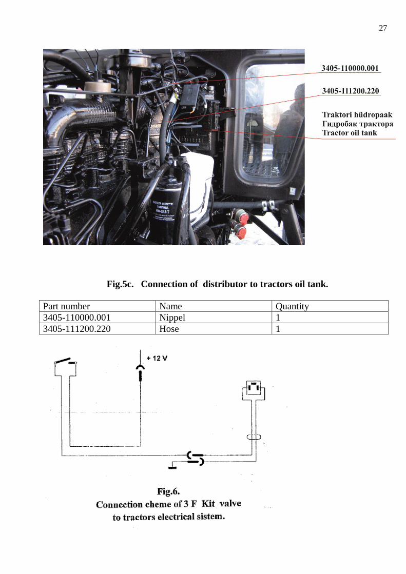
Hydraulic tank cover cup must be substituted for the pipe connector (20, Fig.5a) –
See also Fig. 5C
7.2.2 Mounting and connection of the hydraulic distributor:
Additional distributor (1, Fig.5a) must be mounted on the frame vertical beam
(right or left ) depending on the side of the frontal loader hydraulic system position
by help of the bracket ( 3, Fig.5a ).
Connect the distributor according to the assembly scheme ( Fig.5 and 5a)
by help of flexible hydraulic sleeves.
Observe strictly remarks : “P” – oil feeding from the pump,
“T1” – oil feeding from additional loader distributor to tractor distributor,
“T” – oil outlet flow from additional distributor to the tractor oil tank.
7.2.3 Control unit assembly:
● Assemble the “Joystick” handle inside tractor cabin together with flexible wire pull-
ropes ( Fig. 5b ).
Attention! Incase loader distributor system is mounted on the left side,
pull-ropes must be placed to the cabin’s left side and positioned under the cabin
bottom.
● Connect flexible hydraulic sleeves with the distributor ( 1 ) so that
15
the “Joystick” handle ( 2 ) was in vertical position , and control movements
were corresponding to the scheme ( 3 ) attached.
● Attention! In order to connect pull-ropes to distributor slide valves
make use of shafts “A” and of clutch “B” from distributor assembly set. ( see Fig. 5b )
● Attention! Vertical position of the “Joystick” handle is achieved by
adjustment of pull-rope length by help screw nut “C” on the ends of pull-ropes
and also by help of connecting clutch “A” ( see Fig. 5b )
● Warning! All movements of the Joystick must be smooth without jerks
and without employment of extra force. The wire pull-ropes must not be
twisted/ entangled, and avoid their pressure and rubbing to the moving
tractor parts.
8. CONTROL UNITS.
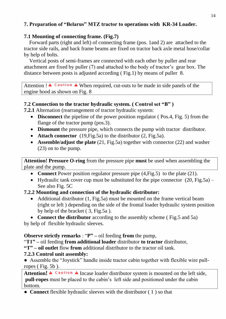
8.1. Frontal Loader Operation Control.
Operation control is effected by a single “Joystick” handle with help of
additional distributor. ( See Fig. 3 ).
Attention! In case there are no operations with loader, the Joystick
handle must be blocked in neutral position.
Scheme Fig. 3 – details:
Handle movement “Backwards or to the Front is corresponding accordingly to Up/Lift or
Down movement of the loader boom.
Handle movement to the extreme forward /until stop/ position – corresponds to the
definite “Flow” mode of the boom.
Handle movement “ to the left, then to the right” – corresponds to bucket filling and
discharging.
Fig. 3 – Frontal loader operation control by Joystick handle.
16
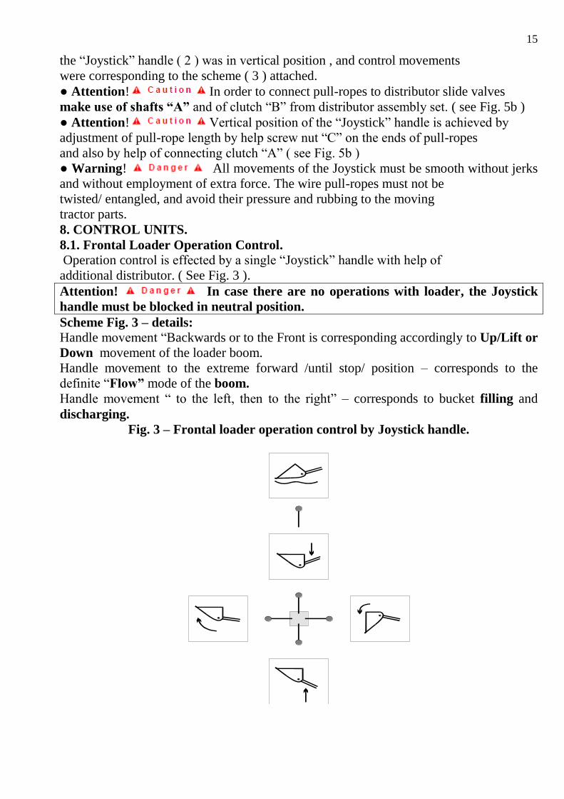
Fig. 4
8.2 Connecting of Front Loader to the tractor.
Position the loader on the parking supports in front of the tractor so, that the
axles “A” of the loader bracket were at the same height level with the locks of
the connecting frame (fig.4).
By moving the tractor cautiously forward, insert loader’s bracket axles into the
connecting frame locking nest. Position fixing rods “F” into the holes of loader
bracket and fix them.
Connect flexible hydraulic system hoses of the loader to the quick - action
clutches of the bracket, according to scheme (Fig.1A ).In case, all previously
required operations are performed correctly, the boom lifting cylinders will be
connected to the left outlets, while bucket turning cylinders - connected to the
right tractor outlets.
Lift the loader’s boom, fold the parking support and fix it to the boom.
17
8.3 Disconnecting of Front Loader from the tractor.
Disconnection of the front loader is performed in the reverse order.
Position the bucket to the ground by front edge so, that there was a free space
between the ground level and the bottom plate equal to 10 – 15˚ .
Unfold parking supports and position them to the ground.
Place loader brackets so, that the distance between their upper ends and the
boom was 50 - 60 mm.
Remove fixing rods “F”
Smoothly turning the bucket and lowering the boom, free the loader
from connecting frame locks (While this operation, the loader, under
its own weight should slip down from connecting frame and rest safely on
parking supports).
Cautiously, without stretching flexible hydraulic hoses, move the tractor
backwards to 150 – 200 mm distance.
By turning the bucket, return bracket axles “A” to the height level of the
connecting frame locks.
Switch off the engine, then by 2-3 movements of the “Joy Stick”
handle relieving loader’s hydraulic system from residual pressure, and finally,
disconnect the quick-action hose clutches.
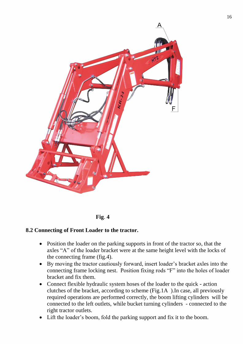
8.4 Connecting and change of implements.
For quick substitution /change/ of implements loader has a special Frame
with “SMS” or “EURO” locking mechanism.
1 2 3
To attach a bucket (or another device) to the loader’s boom, it is necessary
18
to put the “SMS” or “EURO „ locking lever into the “Open” position, mount the bucket
by picking bucket hooks by help of the boom upper axle, toss the bucket into “towards
body” position and put the lock lever into “Close” position.
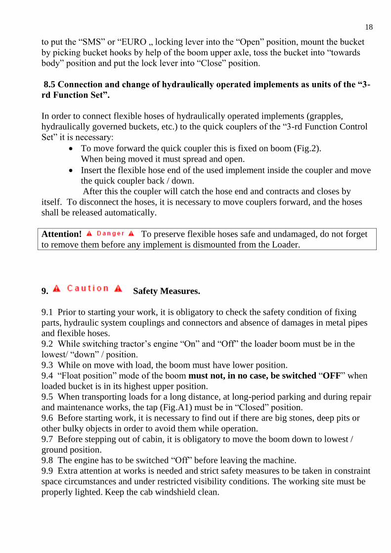
8.5 Connection and change of hydraulically operated implements as units of the “3-
rd Function Set”.
In order to connect flexible hoses of hydraulically operated implements (grapples,
hydraulically governed buckets, etc.) to the quick couplers of the “3-rd Function Control
Set” it is necessary:
To move forward the quick coupler this is fixed on boom (Fig.2).
When being moved it must spread and open.
Insert the flexible hose end of the used implement inside the coupler and move
the quick coupler back / down.
After this the coupler will catch the hose end and contracts and closes by
itself. To disconnect the hoses, it is necessary to move couplers forward, and the hoses
shall be released automatically.
Attention! To preserve flexible hoses safe and undamaged, do not forget
to remove them before any implement is dismounted from the Loader.
9. Safety Measures.
9.1 Prior to starting your work, it is obligatory to check the safety condition of fixing
parts, hydraulic system couplings and connectors and absence of damages in metal pipes
and flexible hoses.
9.2 While switching tractor’s engine “On” and “Off” the loader boom must be in the
lowest/ “down” / position.
9.3 While on move with load, the boom must have lower position.
9.4 “Float position” mode of the boom must not, in no case, be switched “OFF” when
loaded bucket is in its highest upper position.
9.5 When transporting loads for a long distance, at long-period parking and during repair
and maintenance works, the tap (Fig.A1) must be in “Closed” position.
9.6 Before starting work, it is necessary to find out if there are big stones, deep pits or
other bulky objects in order to avoid them while operation.
9.7 Before stepping out of cabin, it is obligatory to move the boom down to lowest /
ground position.
9.8 The engine has to be switched “Off” before leaving the machine.
9.9 Extra attention at works is needed and strict safety measures to be taken in constraint
space circumstances and under restricted visibility conditions. The working site must be
properly lighted. Keep the cab windshield clean.
19
9.10 When working in the vicinity of electric lines and power cables utmost caution must
be exercised.
9.11 When performing any work by frontal loader it is obligatory to use counterweight
not less than 800 kgs.
9.12 Parking of the Loader must be performed at even ground and special attention must
be taken, that the hydraulic system is completely relieved from oil pressure. Only park
the front loader on a stable substrate and with attached implement. Ensure that the
support legs are securely positioned.
9.13 If you use the front loader at low outdoor temperatures, bring the hydraulic system
up to working temperature beforehand. To do this, completely extend and retract all
hydraulic cylinders several times.
9.14 If the tractor has as a seat belt, fasten the seat belt when driving.
9.15 Only control the machine from the driver's seat.
9.16 When driving on curves reduce the speed and lower the load.
9.17 Only the operator should attach and remove the front loader and the implements.
9.18 The recommendation of the manufacturer of a tractor -do not raise cargoes in weight
more than 1200 kg. with a view of safety of the front bridge of a tractor.
10 PROHIBITED !
To disconnect hydraulic system couplings with switched engine
and raised boom.
To operate the loader when quick-linkage device is open.
To lift or transport people on the loader.
To be within loader’s working range and stay under lifted boom.
To try filling the bucket by compressed, bulky, frozen, but not
loosened materials or use loader for crushing such materials.
To exceed the stipulated (specified) maximum working pressure
in loader hydraulic system.
To move with transport speed more than 20 km/h
To operate with working speed more than 6 km/h
To operate on ground slopes exceeding 5˚
To transport loads via rough pitted terrain.
To drive on public roads with loaded implement.
11.Obligatory.
To take care that all loader and tractor warning tables and labels
are visible and undamaged.
To take measures that the load is distributed evenly along bucket
(or other devices) width and strive to place loads symmetrically
relatively to the longitudinal tractor axle.
12. Daily and periodic maintenance is performed together with tractor
maintenance and includes the following procedures:
Control of hydraulic system couplings leakage tightness and check
of hoses and fixing elements safety.
20
Checking condition of all loader joints and hinges and presence of
lubrication inside.
Checking of safe loader fixation to the connecting frame.
Oil level checking in tractor hydraulic tank
(See: tractor instruction).
Lubrication of loader joints and hinges is performed through
available lubrication pressure cups, using “Mobillux”, “Alvania Grease 2”
types of grease.
13. Corrosion Proofing and Storage.
When being stored for more than 3 months, loader 3405.16 must
undergo anti-corrosion proofing as per the following procedures:
Loader hydraulic system must be relieved from residual pressure.
Connecting couplings – to be covered by safety caps and plugs.
Loader is disconnected from the tractor and stationed on parking
supports.
Hydraulic cylinder rods and other unpainted metal surfaces
should be grease-proofed.
Storage is performed under roof cover.
14. Loader Operation and Maintenance.
Careful and professional way of loader operation and maintenance are basic factors for
safe, reliable and long-term service of a front loader.
Attention! While working with loader, Tractor Operation and
Maintenance Instructions must be observed.
Before starting maintenance work, put on your protective equipment (protective overalls,
gloves, protective goggles, safety footwear).
Loader requires timely cleaning and in particular – joints and hinges, hydraulic
cylinder rods, pipelines, hydraulic devices and coupling, fixing mechanisms. Especially,
cleaning is important in frost periods.
Take care of hydraulic clutches and couplings cleanliness. When disconnected, they must
be tightly covered by safety caps and plugs.
Attention! Never search for leaks with your fingers. Use suitable aids
(a piece of wood or cardboard).
21
Avoid damage hydraulic flexible hoses and metal pipes. When oil leakage is observed –
immediate measures to be taken to eliminate it.
Loader undergoes considerable working loads, and therefore, regular checking of bolt-
and-nut tight fixing must be observed.
Attention ! All loader clutches and couplings are of restored type.
When mechanical wear is found (free play, gaps), change replacement bushings
for new ones and, in some cases, substitute axles as well.
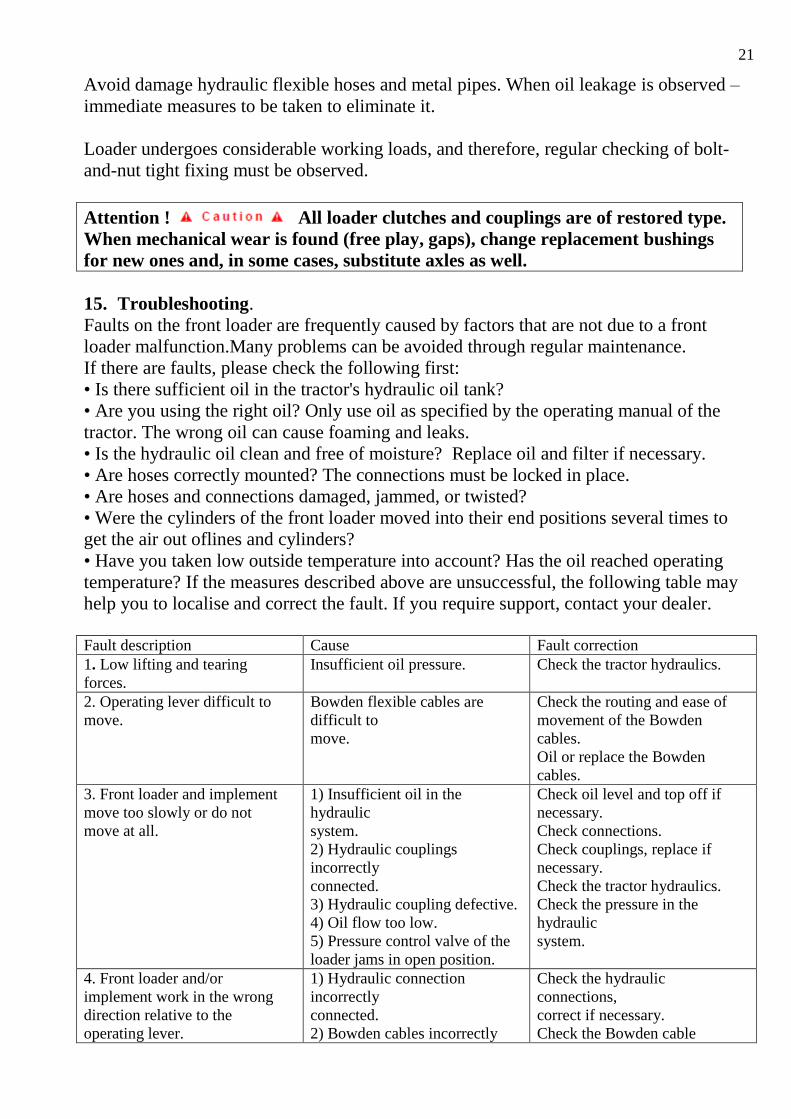
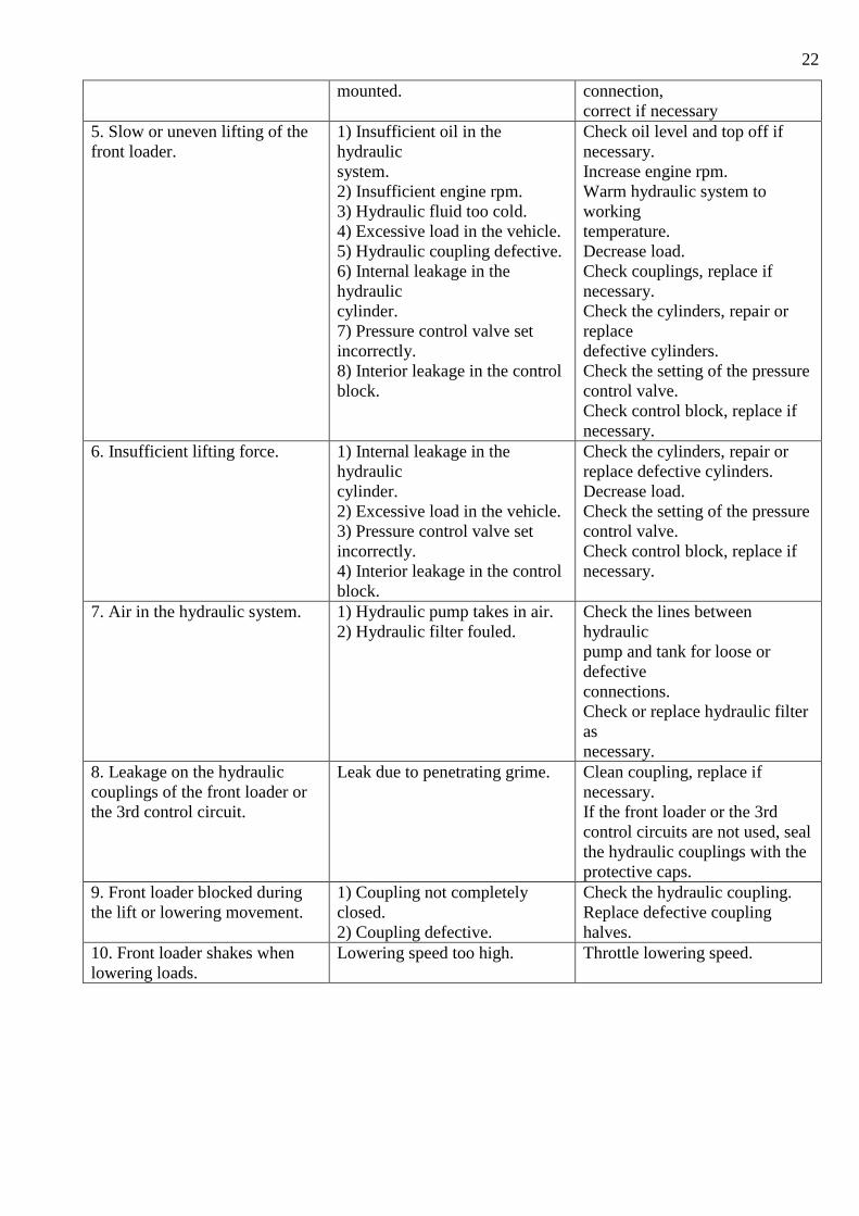
15. Troubleshooting. Faults on the front loader are frequently caused by factors that are not due to a front
loader malfunction.Many problems can be avoided through regular maintenance.
If there are faults, please check the following first:
• Is there sufficient oil in the tractor's hydraulic oil tank?
• Are you using the right oil? Only use oil as specified by the operating manual of the
tractor. The wrong oil can cause foaming and leaks.
• Is the hydraulic oil clean and free of moisture? Replace oil and filter if necessary.
• Are hoses correctly mounted? The connections must be locked in place.
• Are hoses and connections damaged, jammed, or twisted?
• Were the cylinders of the front loader moved into their end positions several times to
get the air out oflines and cylinders?
• Have you taken low outside temperature into account? Has the oil reached operating
temperature? If the measures described above are unsuccessful, the following table may
help you to localise and correct the fault. If you require support, contact your dealer.
Fault description Cause Fault correction 1. Low lifting and tearing
forces.
Insufficient oil pressure. Check the tractor hydraulics.
2. Operating lever difficult to
move.
Bowden flexible cables are
difficult to
move.
Check the routing and ease of
movement of the Bowden
cables.
Oil or replace the Bowden
cables.
3. Front loader and implement
move too slowly or do not
move at all.
1) Insufficient oil in the
hydraulic
system.
2) Hydraulic couplings
incorrectly
connected.
3) Hydraulic coupling defective.
4) Oil flow too low.
5) Pressure control valve of the
loader jams in open position.
Check oil level and top off if
necessary.
Check connections.
Check couplings, replace if
necessary.
Check the tractor hydraulics.
Check the pressure in the
hydraulic
system.
4. Front loader and/or
implement work in the wrong
direction relative to the
operating lever.
1) Hydraulic connection
incorrectly
connected.
2) Bowden cables incorrectly
Check the hydraulic
connections,
correct if necessary.
Check the Bowden cable
22
mounted. connection,
correct if necessary
5. Slow or uneven lifting of the
front loader.
1) Insufficient oil in the
hydraulic
system.
2) Insufficient engine rpm.
3) Hydraulic fluid too cold.
4) Excessive load in the vehicle.
5) Hydraulic coupling defective.
6) Internal leakage in the
hydraulic
cylinder.
7) Pressure control valve set
incorrectly.
8) Interior leakage in the control
block.
Check oil level and top off if
necessary.
Increase engine rpm.
Warm hydraulic system to
working
temperature.
Decrease load.
Check couplings, replace if
necessary.
Check the cylinders, repair or
replace
defective cylinders.
Check the setting of the pressure
control valve.
Check control block, replace if
necessary.
6. Insufficient lifting force. 1) Internal leakage in the
hydraulic
cylinder.
2) Excessive load in the vehicle.
3) Pressure control valve set
incorrectly.
4) Interior leakage in the control
block.
Check the cylinders, repair or
replace defective cylinders.
Decrease load.
Check the setting of the pressure
control valve.
Check control block, replace if
necessary.
7. Air in the hydraulic system. 1) Hydraulic pump takes in air.
2) Hydraulic filter fouled.
Check the lines between
hydraulic
pump and tank for loose or
defective
connections.
Check or replace hydraulic filter
as
necessary.
8. Leakage on the hydraulic
couplings of the front loader or
the 3rd control circuit.
Leak due to penetrating grime. Clean coupling, replace if
necessary.
If the front loader or the 3rd
control circuits are not used, seal
the hydraulic couplings with the
protective caps.
9. Front loader blocked during
the lift or lowering movement.
1) Coupling not completely
closed.
2) Coupling defective.
Check the hydraulic coupling.
Replace defective coupling
halves.
10. Front loader shakes when
lowering loads.
Lowering speed too high. Throttle lowering speed.
23
16. Appendix.
24
25
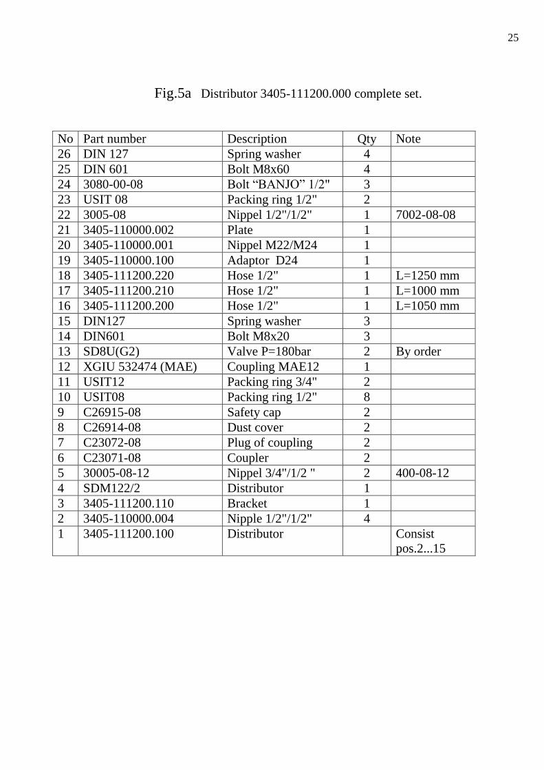
Fig.5a Distributor 3405-111200.000 complete set.
No Part number Description Qty Note
26 DIN 127 Spring washer 4
25 DIN 601 Bolt M8x60 4
24 3080-00-08 Bolt “BANJO” 1/2" 3
23 USIT 08 Packing ring 1/2" 2
22 3005-08 Nippel 1/2"/1/2" 1 7002-08-08
21 3405-110000.002 Plate 1
20 3405-110000.001 Nippel M22/M24 1
19 3405-110000.100 Adaptor D24 1
18 3405-111200.220 Hose 1/2" 1 L=1250 mm
17 3405-111200.210 Hose 1/2" 1 L=1000 mm
16 3405-111200.200 Hose 1/2" 1 L=1050 mm
15 DIN127 Spring washer 3
14 DIN601 Bolt M8x20 3
13 SD8U(G2) Valve P=180bar 2 By order
12 XGIU 532474 (MAE) Coupling MAE12 1
11 USIT12 Packing ring 3/4" 2
10 USIT08 Packing ring 1/2" 8
9 C26915-08 Safety cap 2
8 C26914-08 Dust cover 2
7 C23072-08 Plug of coupling 2
6 C23071-08 Coupler 2
5 30005-08-12 Nippel 3/4"/1/2 " 2 400-08-12
4 SDM122/2 Distributor 1
3 3405-111200.110 Bracket 1
2 3405-110000.004 Nipple 1/2"/1/2" 4
1 3405-111200.100 Distributor Consist
pos.2...15
26
27
Fig.5c. Connection of distributor to tractors oil tank.
Part number Name Quantity
3405-110000.001 Nippel 1
3405-111200.220 Hose 1
28
29