frp lift bridge over the oud rijn: engineering slenderness/media/royalhaskoningdhvcorp… · bridge...
TRANSCRIPT

FRP lift bridge over the Oud Rijn: engineering slenderness
Liesbeth TROMP
FRP Engineer Royal HaskoningDHV, The
Netherlands [email protected]
Liesbeth Tromp has a degree in aerospace engineering (Delft University of Technology), 13 years background in FRP engineering and is involved in FRP guideline development.
Ernst KLAMER
Civil Engineer Royal HaskoningDHV, The Netherlands [email protected]
Ernst Klamer has a PhD-degree in building engineering (Eindhoven University of Technology) and 6 years background in engineering of civil FRP structures.
Summary In a design contest, RHDHV architect Joris Smits entered a challenging asymmetric design for a lift
bridge for the Oude Rijn, Katwijk, the Netherlands. Using the lightweight stiffness of Fiber
Reinforced Polymers (FRP) for the deck structure, he created an extremely thin structure, for its
beauty and to reduce the number of openings of the bridge by increasing the height of the vertical
clearance. The client was thrilled by the design but hesitant to believe the concept was feasible:
such complex shape and slenderness. Royal HaskoningDHV was asked to further develop the
design and demonstrate the technical and economic feasibility of the design. Could such long
slender deck really be achieved? How would it respond to its single lifting arm? This paper
discusses the challenges of the asymmetric design of the bridge and explains the FRP engineering
solution. Dutch Design Recommendation CUR96 [1] has been used for the structural design.
Keywords: analysis, architecture, comfort, feasibility, footbridge, FRP, moveable bridge.
1. Introduction A design contest was held in 2010 between 4 architects in which RHDHV architect Joris Smits
participated with a challenging asymmetric design for a lift bridge for the Oude Rijn, Katwijk, the
Netherlands. The single pillar was inspired by a white heron and reflects the social context of the
area: suburban development on one side, free space on the other. He created an extremely slender
structure, for its beauty and to reduce the number of openings of the bridge by increasing the height
of the vertical clearance.
Figure 1 Design of Footbridge over the Oude Rijn, Katwijk, the Netherlands

The dimensions of the structure are fully based on Fiber Reinforced Polymer (FRP) mechanical properties and a moulding process. FRP was preferred because of its low maintenance and low weight: this way the balance weight, located in the rear of the single balance beam, could be minimised both in volume and kilograms.
The design was selected by the commission consisting of community members and governmental representatives, for both its architecture as well as the competitive costs level of the bridge. The client was thrilled by the design but hesitant to believe the concept was feasible: such complex shape and slenderness. Royal HaskoningDHV was asked to further develop the design and demonstrate the technical and economic feasibility of the design. Could such long slender deck really be achieved? How would it respond to its single lifting arm? This paper discusses the challenges of the asymmetric design of the bridge and explains the analysis and engineering solutions related to the FRP material.
2. Design, dimensions and engineering challenges
2.1 Design principles
The design scope was to develop the architectural design up to a preliminary design level, such that the technical and economic feasibility of the design could be assessed. Additionally, the original architectural design intended to have a mechanical actuator in the top of the pillar. This solution was discarded because of the technical feasibility (too high wind loads) and complications involved in maintenance of the system. A new actuator system had to be developed and integrated into the design. After thorough evaluation it was decided that a single hydraulic cylinder would be the best solution. Application of two cylinders would affect the dimensions of the base-pillar too much. And the redundancy and level of reliability that two cylinders might offer over a single cylinder could as well be achieved by redundancy on a component or system level in the operation system of the hydraulic cylinder.
It was the wish of the Client to further develop and optimise the design (technically) with minimum impact on the architectural design within the original assigned budget.
2.2 Dimensions
The project involves three bridge decks of approximately 20 – 26 m span each, sites for mooring and other civil works typically involved. This paper focusses on the moveable bridge structure.
The deck has a length of 25 m, and a width of 6,30 m. The height of the deck is 0,85 m.
2.3 Engineering challenges
The complexity the asymmetric situation puts on the structure is seen in Figure 2.
Figure 2 Visualisation of the asymmetry of the design
As is seen from Figure 2, the deck is skewed, with an angle of 25°.
The main challenges of the design are:
- asymmetric support of the deck
- skewed deck and curved bridge approach
- limited blocking of water flow => restricted dimensions of pillars
- large span (comfort and wind load)
- low structural height
- integration of collision protection (safety of structure and barriers)
- multi disciplinary design ( optimise for architecture, structural performance, actuator system
within budget)
In addition it is an innovative design that combines the relatively limited experience with the use of
FRP with a complex structural principle, increasing the level of uncertainties in the evaluation.
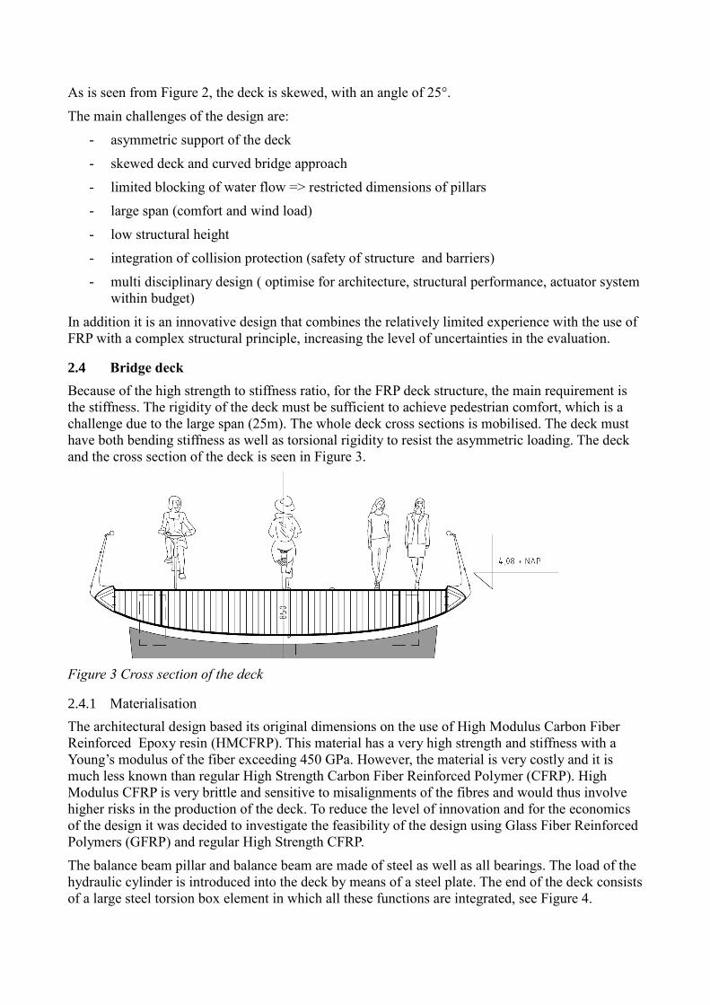
2.4 Bridge deck
Because of the high strength to stiffness ratio, for the FRP deck structure, the main requirement is
the stiffness. The rigidity of the deck must be sufficient to achieve pedestrian comfort, which is a
challenge due to the large span (25m). The whole deck cross sections is mobilised. The deck must
have both bending stiffness as well as torsional rigidity to resist the asymmetric loading. The deck
and the cross section of the deck is seen in Figure 3.
Figure 3 Cross section of the deck
2.4.1 Materialisation
The architectural design based its original dimensions on the use of High Modulus Carbon Fiber
Reinforced Epoxy resin (HMCFRP). This material has a very high strength and stiffness with a
Young’s modulus of the fiber exceeding 450 GPa. However, the material is very costly and it is
much less known than regular High Strength Carbon Fiber Reinforced Polymer (CFRP). High
Modulus CFRP is very brittle and sensitive to misalignments of the fibres and would thus involve
higher risks in the production of the deck. To reduce the level of innovation and for the economics
of the design it was decided to investigate the feasibility of the design using Glass Fiber Reinforced
Polymers (GFRP) and regular High Strength CFRP.
The balance beam pillar and balance beam are made of steel as well as all bearings. The load of the
hydraulic cylinder is introduced into the deck by means of a steel plate. The end of the deck consists
of a large steel torsion box element in which all these functions are integrated, see Figure 4.

From the analysis it was found that a combination of carbon fiber and glass fiber reinforcement is needed to achieve the required performance within the limited height of the deck. The deck is therefore a hybrid structure with CFRP flanges (upper and lower skin) and GFRP webs. It was found necessary to maximise the orientation of the CFRP fibers in lengthwise direction (62,5%). Furthermore two carbon main webs have been introduced to increase the torsional rigidity of the deck. All webs and ribs have a quasi isotropic (QI) lay up (i.e same stiffness in all in plane principal directions) for good shear properties. A GFRP rib was introduced to achieve a proper load introduction of the balance weight. The structure and material scheme is shown in Figure 4.
Figure 4 Material built up of the deck
2.4.2 Balancing and deformation under own weight
Under its dead weight the bridge deck will bend. To prevent sagging of the bridge and ponding, the initial shape of the deck is slightly curved along its axis. This curvature must include an additional compensation of creep deformation, although due to the use of CFRP flanges, creep deformations are minimal. Due to the single support and the skew angle of the deck, torsion is introduced when the deck is balanced and the response is much more complex. To design the support, an analysis was performed for the balanced deck supported on 3 points, such that the effect of the asymmetry on the 4th support can be seen. The rotation of the deck in this situation is shown in Figure 5. Forcing the structure straight would impose high permanent loads on the structure. Trying to correct for these rotational deformation in the initial shape is possible but would complicate the manufacturing of the structure highly. It was seen however that the deformations are very limited; less than 1 degree rotation and can
actually be used for the control of rain water flow. It was decided to allow this torsional deformation and let the support follow this shape of the deck.
Steel torsion box
CFRP flange
QI GFRP sides Steel hinge with GFRP rib QI GFRP webs
QI CFRP webs

Figure 5 Deformation of the deck under dead load and permanent loading (exaggerated).
2.5 Evaluation of deformations (SLS)
In design of FRP bridges the serviceability limit state (SLS) is in general the determining factor.
Analysis was performed for all loads as prescribed in EN1991-2 [2] and load combinations as
prescribed in EN1990 [3]. The design of the FRP structure is performed according to the Dutch
CUR Recommendation 96 for FRP structures in load bearing structures in infrastructure [1]. This
recommendation gives partial factors for the materials as well as conversion factors for the
influence of climate (temperature and moisture) as well as aging (fatigue, creep). Typically as a
conservative assumption, a margin of 20-30% in stiffness is taken into account for aging effects.
2.5.1 Deformation under traffic load
When the bridge is fully loaded with pedestrians the response of the structure is combined bending
and torsion, see Figure 6. The maximum deformation is 56 mm. The Eurocode or bridge codes do
not prescribe any specific deformation limit. As a reference limit value a deformation of L/250
(83mm) is considered. Including aging effects (factor of 1,21), the deformation is within this limit.
It must be noted that the only stiffness requirement that is specified by the Eurocodes is to be
derived from the comfort requirements of the bridge.
.
Figure 6 Deformation under pedestrian loading
2.6 Wind load
The bridge is located next to the coast, where strong winds can occur. The deformation of the bridge
was determined under wind loading of 1,01 kN/m2 and is seen in Figure 7. The maximum

deformation due to wind is 240mm with an additional deformation of 49 mm due to the dead load
of the bridge.
Figure 7 Deformation of the deck under maximum wind loading.
2.7 Comfort analysis
Though vibration of the bridge for small deviations of the criteria is not likely to result in failure of
the bridge, it is crucial for the perception of the quality and for FRP footbridges often the design
determining requirement. Recent developments in the Eurocodes are the identification of traffic classes for pedestrian bridges.
For this bridge normal use is identified as traffic class 3 (0,5 person per m2). For extreme situations
also traffic class 5 is verified (1,5 person per m2), see technical background report EN23984 [2].
The comfort requirements are dealt with in different ways in different countries and this approach is
part of the Dutch national annex of EN1991-2 [2]. The challenge lies in the subjectivity of the
comfort criteria and the reliability of the theoretical model versus reality. Many parameters are
involved, such as the exact stiffness and weight of the structure (i.e. including all overlaps), the
damping of both material and structure as well as the rigidity of the bridge supports.
2.7.1 Eigenfrequency of the deck
Typically when people can move freely, they have a step frequency of around 2 Hz. For vertical and
longitudinal vibrations the induced frequency fi lies between1,25 Hz and 2,3 Hz, and for lateral
vibrations 0,5 Hz ≤ fi ≤ 1,2 Hz. Bridges might also be excited to resonance by the 2nd harmonic of
pedestrian loads with 2,5 Hz ≤ fi ≤ 4,6 Hz. These critical areas must be considered in the design,
which is done by the introduction of a reduction factor Ψ, which equals 1 in these areas, see Figure
8.

Figure 8 reduction factor Ψ for vertical and longitudinal (left) and lateral vibration (right)[4]
Theoretically, a frequency of 2,4 Hz of the bridge would allow a reduction factor of 0. Because of
the expected deviations between the theoretical analysis and the uncertainties in the many
parameters involved, as well as aging effects of the material over the life time of the bridge, this is
considered not a robust or safe design assumption. It was decided to also apply a reduction factor Ψ
of 0,25 for this region where the frequency between 2.3 – 3.4Hz.
Point of attention for FRP bridges is that the weight of the pedestrian load is significant and its
effect must be included in the design. The first eigenfrequencies have been determined by Finite
Element Analysis and are 2.9 Hz for the vertical mode (Figure 9) and 3.3 Hz for the lateral mode
(Figure 10). The vertical mode is within the critical area, the closed shape makes the deck
sufficiently stable for lateral deformations.
Figure 9 first mode (vertical) 2.9 Hz.
Figure 10 First lateral mode 3.3 Hz.
2.7.2 Parameter study
The allowable vertical acceleration, resulting from the vibration is the actual comfort criteria. The
requirement for the bridge is Comfort Class 2 (CC2), with a maximum vertical acceleration of <
0,7 m/s2, to be in line with [3]. The behaviour of the bridge was analysed with and without aging
effects. As a conservative assumption the reduction factor Ψ was set to 0,25. A damping of 1% was
assumed for the material, which is a realistically conservative value for rigid FRP’s with high fiber
volume fractions, and similar to the damping of timber. In addition the sensitivity of the outcome or
effect of a 10% lower stiffness or 10% higher mass was investigated resulting in a lower
eigenfrequency of 2,5 Hz. With these parameters, the calculated acceleration lies in the range of 0,3
m/s2 to 0,45 m/s
2, which is within CC2. In this case according to Figure 8, the shift is in the
favourable direction. A margin of at least 30% in stiffness or mass is present in the design.
Special attention is needed for the analysis of joggers. For long bridges 10 joggers are to be
assumed, that all run in the same frequency. Based on a simplified analysis, placing the joggers in

the middle of the bridge, the resulting eigenfrequency is 3,1Hz, which is near to the critical excitation frequency of joggers. The response to joggers is not within the comfort criteria and the response is potentially very lively. However, the site of the bridge is not a typical area for jogging. The effect of this load on the structure in the analysis can be significant whereas in practice the duration of the load is short, which means that the response of the bridge can be much more favourable [5].
Because of the many influencing factors it is recommended to verify the actual behaviour of the bridge after realisation. The actual damping of the structure and rigidity of the support will result in a better response. It is recommended to take precautions for the placement of dampers in the design for the bridge, to solve any vibration issues if the behaviour of the bridge is not as desired.
2.8 ULS evaluation
Maximum stresses occur at the areas of load introduction (support and balance beam hinge). The maximum stresses in the global structure are far below the design values due to the SLS criteria. For the flange a minimum margin to the allowable design value of 3 was found, and a margin of at least 5 for the webs.
3. Conclusions It has been demonstrated that FRP is a very suitable material for this bridge and that it makes the complex architecture of the bridge feasible both technically as well as economically.
An important point of attention of the design is the behaviour of the bridge on its supports, especially in relation to its lively response. A risk was identified that the bridge might rotate on its supports and can come loose from a support in certain loading conditions, such as joggers or certain pedestrian loadings. Because of the many influencing factors it is recommended to take precautions in the design for this behaviour, for example include a space for the placement of dampers or a locking pin. In addition it is recommended to make a more detailed analysis of the response of the bridge both in the further analysis as well as the installation phase when many of the unknown effects can be included in a practical examination.
4. Acknowledgement The author wishes to acknowledge the architect Joris Smits (Royal HaskoningDHV) and the Client, the municipalities of Katwijk and Oegstgeest, for making this innovative design possible.
5. References [1] CUR COMMISSION C124, “Recommendation 96 “Fibre-Reinforced Polymers in Civil
Load-Bearing Structures” , CUR Gouda, September 2003.
[2] “EN 1991-2 Eurocode 1: Actions on structures – Part 2: Traffic loads on bridges”, CEN Brussels, December 2011.
[3] “EN 1990 Eurocode 0: Basis of structural design”, CEN Brussels, December 2011.
[4] EUR 23984 EN; Design of Lightweight Footbridges for Human Induced Vibrations; JRC, May 2009.
[5] “Footbridges, Assessment of vibrational behaviour of footbridges under pedestrian loading” SETRA, October 2006, pp.14.