fs1 field service guide.pdf
TRANSCRIPT
Oracle FS1-2 Flash Storage System
Field Service Guide
Part Number E41586-01Oracle FS1-2 Flash Storage System release 6.1.0
2014 October
Copyright © 2005, 2014, Oracle and/or its affiliates. All rights reserved.
This software and related documentation are provided under a license agreement containing restrictions onuse and disclosure and are protected by intellectual property laws. Except as expressly permitted in yourlicense agreement or allowed by law, you may not use, copy, reproduce, translate, broadcast, modify,license, transmit, distribute, exhibit, perform, publish or display any part, in any form, or by any means.Reverse engineering, disassembly, or decompilation of this software, unless required by law forinteroperability, is prohibited.
The information contained herein is subject to change without notice and is not warranted to be error-free. Ifyou find any errors, please report them to us in writing.
If this is software or related documentation that is delivered to the U.S. Government or anyone licensing it onbehalf of the U.S. Government, the following notice is applicable:
U.S. GOVERNMENT RIGHTS Programs, software, databases, and related documentation and technicaldata delivered to U.S. Government customers are "commercial computer software" or "commercial technicaldata" pursuant to the applicable Federal Acquisition Regulation and agency-specific supplementalregulations. As such, the use, duplication, disclosure, modification, and adaptation shall be subject to therestrictions and license terms set forth in the applicable Government contract, and, to the extent applicableby the terms of the Government contract, the additional rights set forth in FAR 52.227-19, CommercialComputer Software License (December 2007). Oracle USA, Inc., 500 Oracle Parkway, Redwood City, CA94065.
This software or hardware is developed for general use in a variety of information management applications.It is not developed or intended for use in any inherently dangerous applications, including applications thatmay create a risk of personal injury. If you use this software or hardware in dangerous applications, then youshall be responsible to take all appropriate fail-safe, backup, redundancy, and other measures to ensure itssafe use. Oracle Corporation and its affiliates disclaim any liability for any damages caused by use of thissoftware or hardware in dangerous applications.
Oracle and Java are registered trademarks of Oracle and/or its affiliates. Other names may be trademarks oftheir respective owners.
This software or hardware and documentation may provide access to or information on content, productsand services from third parties. Oracle Corporation and its affiliates are not responsible for and expresslydisclaim all warranties of any kind with respect to third-party content, products, and services. OracleCorporation and its affiliates will not be responsible for any loss, costs, or damages incurred due to youraccess to or use of third-party content, products, or services.
Copyright © 2005, 2014, Oracle et/ou ses affiliés. Tous droits réservés.
Ce logiciel et la documentation qui l’accompagne sont protégés par les lois sur la propriété intellectuelle. Ilssont concédés sous licence et soumis à des restrictions d’utilisation et de divulgation. Sauf disposition devotre contrat de licence ou de la loi, vous ne pouvez pas copier, reproduire, traduire, diffuser, modifier,breveter, transmettre, distribuer, exposer, exécuter, publier ou afficher le logiciel, même partiellement, sousquelque forme et par quelque procédé que ce soit. Par ailleurs, il est interdit de procéder à toute ingénierieinverse du logiciel, de le désassembler ou de le décompiler, excepté à des fins d’interopérabilité avec deslogiciels tiers ou tel que prescrit par la loi.
Les informations fournies dans ce document sont susceptibles de modification sans préavis. Par ailleurs,Oracle Corporation ne garantit pas qu’elles soient exemptes d’erreurs et vous invite, le cas échéant, à lui enfaire part par écrit.
Si ce logiciel, ou la documentation qui l’accompagne, est concédé sous licence au Gouvernement des Etats-Unis, ou à toute entité qui délivre la licence de ce logiciel ou l’utilise pour le compte du Gouvernement desEtats-Unis, la notice suivante s’applique :
U.S. GOVERNMENT RIGHTS. Programs, software, databases, and related documentation and technicaldata delivered to U.S. Government customers are "commercial computer software" or "commercial technicaldata" pursuant to the applicable Federal Acquisition Regulation and agency-specific supplementalregulations. As such, the use, duplication, disclosure, modification, and adaptation shall be subject to therestrictions and license terms set forth in the applicable Government contract, and, to the extent applicableby the terms of the Government contract, the additional rights set forth in FAR 52.227-19, CommercialComputer Software License (December 2007). Oracle America, Inc., 500 Oracle Parkway, Redwood City,CA 94065.
Ce logiciel ou matériel a été développé pour un usage général dans le cadre d’applications de gestion desinformations. Ce logiciel ou matériel n’est pas conçu ni n’est destiné à être utilisé dans des applications àrisque, notamment dans des applications pouvant causer des dommages corporels. Si vous utilisez celogiciel ou matériel dans le cadre d’applications dangereuses, il est de votre responsabilité de prendretoutes les mesures de secours, de sauvegarde, de redondance et autres mesures nécessaires à sonutilisation dans des conditions optimales de sécurité. Oracle Corporation et ses affiliés déclinent touteresponsabilité quant aux dommages causés par l’utilisation de ce logiciel ou matériel pour ce typed’applications.
Oracle et Java sont des marques déposées d’Oracle Corporation et/ou de ses affiliés.Tout autre nommentionné peut correspondre à des marques appartenant à d’autres propriétaires qu’Oracle.
Ce logiciel ou matériel et la documentation qui l’accompagne peuvent fournir des informations ou des liensdonnant accès à des contenus, des produits et des services émanant de tiers. Oracle Corporation et sesaffiliés déclinent toute responsabilité ou garantie expresse quant aux contenus, produits ou servicesémanant de tiers. En aucun cas, Oracle Corporation et ses affiliés ne sauraient être tenus pourresponsables des pertes subies, des coûts occasionnés ou des dommages causés par l’accès à descontenus, produits ou services tiers, ou à leur utilisation.

ContentsList of Tables .............................................................................................................................17
List of Figures............................................................................................................................19
Related Documentation.............................................................................................................38Oracle Resources......................................................................................................................39
Chapter 1: Introduction to Oracle FS1-2 System Service Procedures ......................................40Oracle FS System Service Procedures ...............................................................................40
Controller Components...................................................................................................40Drive Enclosure Components.........................................................................................44Pilot Components ...........................................................................................................48Warnings and Cautions ..................................................................................................51Electrostatic Discharge Precautions...............................................................................51Required Tools ...............................................................................................................51
Guided Maintenance............................................................................................................52Guided Maintenance Overview ......................................................................................52Guided Maintenance Replaceable Components ............................................................54Access Guided Maintenance..........................................................................................55
Access to Replace a Controller Component (1) ........................................................55Access to Replace a Controller Component (2) ........................................................56Access to Replace a Drive Enclosure Component ...................................................57Access to Replace a Pilot Component ......................................................................57
Chapter 2: Oracle FS1–2 Global Procedures and Rail Kit Installation ......................................58Component Placement ........................................................................................................58Component Numbering........................................................................................................60Oracle FS System Rack Hardware Specifications...............................................................62Prepare the Rack ................................................................................................................64
Remove the Doors From a Rack ....................................................................................65Remove a Side Panel From a Rack ...............................................................................65Rack Installation Safety Precautions .............................................................................66
System-Wide Procedures ....................................................................................................66Data Backups .................................................................................................................66Power Cycling.................................................................................................................67
Controller Rails ....................................................................................................................67Controller Rail Kits ..........................................................................................................68Install the Rack Rails for the Controller ..........................................................................69Install the Slide Rails for the Controller ..........................................................................72Install the Controller CMA...............................................................................................77Insert the Controller Into a Rack.....................................................................................80Verify Operation of the Slide Rails and the CMA............................................................81
Drive Enclosure Rails...........................................................................................................83Drive Enclosure Rail Kits ................................................................................................86
4

Install Drive Enclosure Rails ...........................................................................................88Install Rails for DE2-24P Drive Enclosures ....................................................................88
Install Rails in Threaded Racks.................................................................................88Install Rails in Square or Round Hole Racks ............................................................91
Install Rails for DE2-24C Drive Enclosures ....................................................................94Insert a DE2-24P Drive Enclosure Into a Rack ..............................................................98Insert a DE2-24C Drive Enclosure Into a Rack ............................................................101
Pilot Rails ...........................................................................................................................104Pilot Rail Kits.................................................................................................................104Install the Rack Rails for the Pilot .................................................................................105Install the Slide Rails for the Pilot .................................................................................107Install the Pilot CMA .....................................................................................................108Insert the Pilot into a Rack............................................................................................110Verify Operation of the Slide Rails and the CMA..........................................................112
Chapter 3: Controller Replacement Procedures .....................................................................114Controller Overview ...........................................................................................................114Replace Controller Air Filter ...............................................................................................114
Remove an Air Filter .....................................................................................................115Insert an Air Filter .........................................................................................................116
Replace a Controller Fan Module ......................................................................................117Prepare the Component for Replacement ....................................................................119Remove the Controller Power Supply Cords................................................................120Slide Controller to Service Position ..............................................................................121Open the Controller Top Cover ....................................................................................121Remove a Fan Module .................................................................................................122Insert a Fan Module......................................................................................................123Close the Controller Top Cover ....................................................................................124Complete the Component Replacement ......................................................................125Verify Controller Component Status .............................................................................125
Replace a Controller Power Supply ...................................................................................126Prepare the Component for Replacement ....................................................................128Remove the Power Cords ............................................................................................128Remove a Power Supply ..............................................................................................129Insert a Power Supply ..................................................................................................130Insert the Power Cords.................................................................................................131Verify Controller Component Status .............................................................................131
Replace a Controller Energy Storage Module (ESM) ........................................................131Prepare the Component for Replacement ....................................................................133Remove an Air Filter .....................................................................................................134Remove a Controller Energy Storage Module (ESM)...................................................135Insert an Energy Storage Module.................................................................................136Power On the Controller ...............................................................................................138Insert an Air Filter .........................................................................................................138Verify Controller Component Status .............................................................................138
Replace a Controller Riser ................................................................................................139Prepare the Component for Replacement ....................................................................140
Contents
5
Remove the Controller Power Supply Cords................................................................141Slide Controller to Service Position ..............................................................................142Disconnect Controller Cabling ......................................................................................143Open the Controller Top Cover ....................................................................................143Remove a Riser ...........................................................................................................143Insert a Riser ................................................................................................................146Close the Controller Top Cover ....................................................................................148Reconnect Controller Cabling.......................................................................................148Complete the Component Replacement ......................................................................149Verify Controller Component Status .............................................................................149
Replace a Controller HBA..................................................................................................149Prepare the Component for Replacement ....................................................................151Remove the Controller Power Supply Cords................................................................152Slide Controller to Service Position ..............................................................................152Disconnect Controller Cabling ......................................................................................153Open the Controller Top Cover ....................................................................................154Remove a Riser ...........................................................................................................154Remove an HBA...........................................................................................................157Insert an HBA ...............................................................................................................158Insert a Riser ................................................................................................................160Close the Controller Top Cover ....................................................................................162Reconnect Controller Cabling.......................................................................................162Complete the Component Replacement ......................................................................163Verify Controller Component Status .............................................................................163
Replace a Controller DIMM................................................................................................163Prepare the Component for Replacement ....................................................................166Remove the Controller Power Supply Cords................................................................167Slide Controller to Service Position ..............................................................................167Open the Controller Top Cover ....................................................................................168Remove an Air Filter .....................................................................................................169Raise the Drive Compartment to Service Position .......................................................170Remove an Air Duct .....................................................................................................173Remove a DIMM...........................................................................................................174Insert a DIMM ...............................................................................................................175Lower the Drive Compartment .....................................................................................176Insert an Air Duct ..........................................................................................................177Insert an Air Filter .........................................................................................................177Close the Controller Top Cover ....................................................................................178Complete the Component Replacement ......................................................................179Verify Controller Component Status .............................................................................179
Replace a Controller NV-DIMM .........................................................................................180Prepare the Component for Replacement ....................................................................182Remove the Controller Power Supply Cords................................................................183Slide Controller to Service Position ..............................................................................183Open the Controller Top Cover ....................................................................................184Raise the Drive Compartment to Service Position .......................................................185Remove an Air Duct .....................................................................................................187
Contents
6

Remove an NV-DIMM...................................................................................................189Insert an NVDIMM ........................................................................................................189Insert an Air Duct ..........................................................................................................190Lower the Drive Compartment .....................................................................................190Close the Controller Top Cover ....................................................................................191Complete the Component Replacement ......................................................................192Verify Controller Component Status .............................................................................192
Replace a Controller ESM Backplane ...............................................................................193Prepare the Component for Replacement ....................................................................194Remove the Controller Power Supply Cords................................................................195Slide Controller to Service Position ..............................................................................195Remove Components From the Controller ..................................................................196
Remove an Air Filter................................................................................................197Open the Controller Top Cover ...............................................................................198Remove a Controller Energy Storage Module (ESM) .............................................199
Raise the Drive Compartment to Service Position .......................................................200Remove a Backplane ...................................................................................................202Insert the Backplane.....................................................................................................204Insert Components on the Controller............................................................................207
Insert an Energy Storage Module ...........................................................................207Insert an Air Filter ....................................................................................................209Close the Controller Top Cover...............................................................................209
Complete the Component Replacement ......................................................................210Verify Controller Component Status .............................................................................210
Replace a Controller Heat Sink..........................................................................................211Prepare the Component for Replacement ....................................................................212Remove the Controller Power Supply Cords................................................................213Slide Controller to Service Position ..............................................................................213Open the Controller Top Cover ....................................................................................214Remove an Air Duct .....................................................................................................215Raise the Drive Compartment to Service Position .......................................................217Remove a Heat Sink.....................................................................................................219Insert a Heat Sink .........................................................................................................220Insert an Air Duct ..........................................................................................................221Close the Controller Top Cover ....................................................................................221Lower the Drive Compartment .....................................................................................222Complete the Component Replacement ......................................................................223Verify Controller Component Status .............................................................................223
Replace a Controller CPU..................................................................................................224Prepare the Component for Replacement ....................................................................226Remove the Controller Power Supply Cords................................................................227Slide Controller to Service Position ..............................................................................228Open the Controller Top Cover ....................................................................................228Remove an Air Duct .....................................................................................................229Raise the Drive Compartment to Service Position .......................................................231Remove a Heat Sink.....................................................................................................233Remove a CPU.............................................................................................................234
Contents
7

Insert a CPU .................................................................................................................235Insert a Heat Sink .........................................................................................................236Close the Controller Top Cover ....................................................................................237Lower the Drive Compartment .....................................................................................238Complete the Component Replacement ......................................................................239Verify Controller Component Status .............................................................................239
Replace a Controller Identification Display ........................................................................239Prepare the Component for Replacement ....................................................................240Slide Controller to Service Position ..............................................................................241Remove the Controller Power Supply Cords................................................................242Remove an Air Filter .....................................................................................................243Open the Controller Top Cover ....................................................................................244Remove a Controller Identification Display...................................................................245Insert a Controller Identification Display .......................................................................247Close the Controller Top Cover ....................................................................................247Power On the Controller ...............................................................................................248Insert an Air Filter .........................................................................................................248Slide Controller to Rack Position ..................................................................................249Verify Controller Component Status .............................................................................249
Replace a Controller LED Alarm Assembly .......................................................................249Prepare the Component for Replacement ....................................................................252Remove the Controller Power Supply Cords................................................................252Slide Controller to Service Position ..............................................................................253(Optional) Remove Controller Chassis From Rack ......................................................254Remove Components From the Controller ..................................................................255
Open the Controller Top Cover ...............................................................................255Remove an Air Filter................................................................................................256Raise the Drive Compartment to Service Position ..................................................257Remove an Air Duct ................................................................................................259
Remove an LED Alarm Assembly ................................................................................261Insert an LED Alarm Assembly.....................................................................................263Insert Components on the Controller............................................................................266
Insert an Air Duct ....................................................................................................266Lower the Drive Compartment ...............................................................................267Insert an Air Filter ....................................................................................................267Close the Controller Top Cover...............................................................................268
Insert the Controller Onto the Rack ..............................................................................269Insert Controller Chassis Onto Rack.......................................................................269Slide Controller to Rack Position.............................................................................270Power On the Controller..........................................................................................270Verify Controller Component Status........................................................................270
Replace a Controller Motherboard.....................................................................................270Prepare the Component for Replacement ....................................................................273Remove the Controller Power Supply Cords................................................................274Slide Controller to Service Position ..............................................................................275Disconnect Controller Cabling ......................................................................................275(Optional) Remove Controller Chassis From Rack ......................................................276
Contents
8
Remove Components From the Controller ..................................................................276Open the Controller Top Cover ...............................................................................276Remove an Air Filter................................................................................................277Remove a Fan Module............................................................................................278Remove the Fan Compartment ...............................................................................279Remove an Air Duct ................................................................................................280Raise the Drive Compartment to Service Position ..................................................282Remove a Riser ......................................................................................................284Remove a Power Distribution Board (PDB) Cover..................................................286Remove a Motherboard ..........................................................................................288Remove a DIMM .....................................................................................................290Remove an NV-DIMM .............................................................................................291Remove a Heat Sink ...............................................................................................291Remove a CPU .......................................................................................................292About Controller Motherboard Cables.....................................................................294Remove Motherboard Cables .................................................................................296
Insert Components on the Controller............................................................................296Insert a Power Distribution Board (PDB) Cover ......................................................296Insert Motherboard Cables......................................................................................298Insert an NVDIMM...................................................................................................298Insert a DIMM..........................................................................................................298Insert a CPU............................................................................................................299Insert a Heat Sink....................................................................................................300Insert a Riser ...........................................................................................................301Insert a Motherboard...............................................................................................303Lower the Drive Compartment ...............................................................................304Insert an Air Duct ....................................................................................................305Insert the Fan Compartment ...................................................................................305Insert a Fan Module ................................................................................................306Insert an Air Filter ....................................................................................................307Close the Controller Top Cover...............................................................................308
Reconnect Controller Cabling.......................................................................................309Slide Controller to Rack Position ..................................................................................309Power On the Controller ...............................................................................................310Verify Controller Component Status .............................................................................310Update the Controller BIOS .........................................................................................310
Replace Controller Motherboard Cables............................................................................313Prepare the Component for Replacement ....................................................................316Remove the Controller Power Supply Cords................................................................317Disconnect Controller Cabling ......................................................................................317Slide Controller to Service Position ..............................................................................318(Optional) Remove Controller Chassis From Rack ......................................................319Remove Components From the Controller ..................................................................319
Open the Controller Top Cover ...............................................................................319Remove a Fan Module............................................................................................320Remove the Fan Compartment ...............................................................................321
Remove Motherboard Cables.......................................................................................322
Contents
9
Insert Motherboard Cables ...........................................................................................322Insert Components on the Controller............................................................................323
Insert the Fan Compartment ...................................................................................323Insert a Fan Module ................................................................................................323Close the Controller Top Cover...............................................................................324
Insert the Controller Onto the Rack ..............................................................................325Insert Controller Chassis Onto Rack.......................................................................325Slide Controller to Rack Position.............................................................................326Reconnect Controller Cabling .................................................................................326Power On the Controller..........................................................................................326Verify Controller Component Status........................................................................326
Replace a Controller Power Distribution Board .................................................................327Prepare the Component for Replacement ....................................................................329Remove the Controller Power Supply Cords................................................................329Slide Controller to Service Position ..............................................................................330Disconnect Controller Cabling ......................................................................................331(Optional) Remove Controller Chassis From Rack ......................................................332Remove Components From the Controller ..................................................................332
Remove a Power Supply.........................................................................................332Remove an Air Filter................................................................................................334Open the Controller Top Cover ...............................................................................335Remove a Fan Module............................................................................................336Remove the Fan Compartment ...............................................................................336Raise the Drive Compartment to Service Position ..................................................337Remove an Air Duct ................................................................................................340Remove a Riser ......................................................................................................341Remove Motherboard Cables .................................................................................343
Remove a Power Distribution Board (PDB)..................................................................343Insert a Power Distribution Board (PDB) ......................................................................346Insert Components on the Controller............................................................................348
Insert Motherboard Cables......................................................................................348Insert a Riser ...........................................................................................................349Insert an Air Duct ....................................................................................................351Lower the Drive Compartment ...............................................................................351Insert the Fan Compartment ...................................................................................352Insert a Fan Module ................................................................................................353Close the Controller Top Cover...............................................................................354Insert a Power Supply .............................................................................................354Insert an Air Filter ....................................................................................................355
Insert the Controller Onto the Rack ..............................................................................356Insert Controller Chassis Onto Rack.......................................................................356Reconnect Controller Cabling .................................................................................356Slide Controller to Rack Position.............................................................................356Power On the Controller..........................................................................................357Verify Controller Component Status........................................................................357
Contents
10

Chapter 4: Drive Enclosure Replacement Procedures............................................................358Drive Enclosure Overview..................................................................................................358Drive Enclosure Drive Replacement ..................................................................................360Replace a Drive Enclosure Drive .......................................................................................362
Prepare a Drive Enclosure for Component Replacement ............................................362Remove a Drive............................................................................................................363Insert a Drive ................................................................................................................365Verify the Status of a Drive Enclosure Component ......................................................367
Replace an I/O Module ......................................................................................................367Prepare a Drive Enclosure for Component Replacement ............................................369Remove an I/O Module.................................................................................................370Insert an I/O Module .....................................................................................................371Verify the Status of a Drive Enclosure Component ......................................................372
Replace a Power Cooling Module......................................................................................372Prepare a Drive Enclosure for Component Replacement ............................................374Remove a Power Cooling Module ................................................................................375Insert a Power Cooling Module ....................................................................................375Verify the Status of a Drive Enclosure Component ......................................................377
Replace a Drive Enclosure Chassis...................................................................................378Replace a Drive Enclosure (Data Accessible) ..............................................................379
Migrate Data Off of a Drive Enclosure ....................................................................379Power Off a Drive Enclosure...................................................................................380Remove a Drive Enclosure .....................................................................................381Insert a Replacement Drive Enclosure into a Rack (DE2-24P)...............................382Insert a Replacement Drive Enclosure into a Rack (DE2-24C) ..............................385Power On a Drive Enclosure...................................................................................388Accept the Drives for a Replacement Drive Enclosure ...........................................388Add Drive Groups to the Storage Domain...............................................................388
Replace a Drive Enclosure (Data Inaccessible) ...........................................................388Determine the Primary Drive Group........................................................................389Shut Down the Oracle FS System ..........................................................................390Power Off a Drive Enclosure...................................................................................390Remove a Drive Enclosure .....................................................................................391Insert a Replacement Drive Enclosure into a Rack (DE2-24P)...............................392Insert a Replacement Drive Enclosure into a Rack (DE2-24C) ..............................395Power On a Drive Enclosure...................................................................................398Restart the Oracle FS System ................................................................................398Verify the Replacement of a Drive Enclosure ........................................................398
Chapter 5: Pilot Replacement Procedures ..............................................................................399Pilot Overview ....................................................................................................................399Replace a Pilot Battery .....................................................................................................399
Prepare a Pilot for Component Replacement ...............................................................401Power Off the Pilot........................................................................................................402Slide Pilot to Service Position.......................................................................................402Open Pilot Fan Door .....................................................................................................403Open Pilot Top Cover ...................................................................................................404
Contents
11
Remove a Battery .........................................................................................................404Insert a Battery .............................................................................................................405Close Pilot Top Cover...................................................................................................406Close Pilot Fan Door ....................................................................................................407Slide Pilot to Rack Position...........................................................................................407Connect Power Cords On the Pilot...............................................................................408Verify Component Replacement on the Standby Pilot .................................................408Verify Component Replacement on the Active Pilot .....................................................409
Replace a Pilot SAS HBA .................................................................................................409Prepare a Pilot for Component Replacement ...............................................................411Power Off the Pilot........................................................................................................411Slide Pilot to Service Position.......................................................................................412Open Pilot Fan Door .....................................................................................................413Open Pilot Top Cover ...................................................................................................414Remove a SAS HBA.....................................................................................................414Insert a SAS HBA .........................................................................................................415Close Pilot Top Cover...................................................................................................415Close Pilot Fan Door ....................................................................................................416Slide Pilot to Rack Position...........................................................................................417Connect Power Cords On the Pilot...............................................................................417Verify Component Replacement on the Standby Pilot .................................................418Verify Component Replacement on the Active Pilot .....................................................418
Replace a Pilot Riser .........................................................................................................418Prepare a Pilot for Component Replacement ...............................................................420Power Off the Pilot........................................................................................................421Slide Pilot to Service Position.......................................................................................421Open Pilot Fan Door .....................................................................................................422Open Pilot Top Cover ...................................................................................................423Remove a Riser ............................................................................................................423Insert a Riser ................................................................................................................425Close Pilot Top Cover...................................................................................................426Close Pilot Fan Door ....................................................................................................427Slide Pilot to Rack Position...........................................................................................427Connect Power Cords On the Pilot...............................................................................428Verify Component Replacement on the Standby Pilot .................................................428Verify Component Replacement on the Active Pilot .....................................................429
Replace a Pilot Power Supply ...........................................................................................429Prepare a Pilot for Component Replacement ...............................................................430Remove a Power Supply ..............................................................................................431Insert a Power Supply ..................................................................................................432Verify Power Supply Replacement on a Pilot ...............................................................432
Replace a Pilot Fan Module ..............................................................................................433Prepare a Pilot for Component Replacement ...............................................................434Slide Pilot to Service Position.......................................................................................435Open Pilot Fan Door .....................................................................................................436Remove a Fan Module .................................................................................................437Insert a Fan Module......................................................................................................438
Contents
12

Close Pilot Fan Door ....................................................................................................438Slide Pilot to Rack Position...........................................................................................439Verify Component Replacement on the Standby Pilot .................................................439Verify Component Replacement on the Active Pilot .....................................................440
Replace a Pilot DIMM .......................................................................................................440Prepare a Pilot for Component Replacement ...............................................................441Power Off the Pilot........................................................................................................442Slide Pilot to Service Position.......................................................................................443Open Pilot Fan Door .....................................................................................................444Open Pilot Top Cover ...................................................................................................445Remove a Pilot DIMM...................................................................................................445Insert a Pilot DIMM .......................................................................................................446Close Pilot Top Cover...................................................................................................447Close Pilot Fan Door ....................................................................................................448Slide Pilot to Rack Position...........................................................................................448Connect Power Cords On the Pilot...............................................................................449Verify Component Replacement on the Standby Pilot .................................................449Verify Component Replacement on the Active Pilot .....................................................449
Replace a Pilot Chassis .....................................................................................................449Prepare a Pilot for Component Replacement ...............................................................451Power Off the Pilot........................................................................................................452Disconnect Pilot Cabling...............................................................................................452Slide Pilot to Service Position.......................................................................................453Remove Pilot Chassis From Rack................................................................................455Open Pilot Fan Door .....................................................................................................456Open Pilot Top Cover ...................................................................................................456Remove Components From the Pilot ...........................................................................457
Remove a Power Supply.........................................................................................457Remove a Fan Module............................................................................................458Remove the Fan Compartment ...............................................................................459Remove a Pilot DIMM .............................................................................................459Remove a Heat Sink ...............................................................................................460Remove a Pilot CPU ...............................................................................................461Remove a Battery ...................................................................................................462Remove a Riser.......................................................................................................463Remove a SAS HBA ...............................................................................................464Remove a SAS HDD...............................................................................................464Remove a Disk Backplane ......................................................................................465
Insert Components on the Pilot ....................................................................................468Insert a Disk Backplane ..........................................................................................468Insert a SAS HDD ...................................................................................................470Insert a SAS HBA....................................................................................................471Insert a Riser ...........................................................................................................471Insert a Battery ........................................................................................................472Insert a Pilot CPU....................................................................................................473Insert a Heat Sink....................................................................................................474Insert a Pilot DIMM..................................................................................................474
Contents
13

Insert the Fan Compartment ...................................................................................475Insert a Fan Module ................................................................................................475Insert the Fan Compartment ...................................................................................476
Close Pilot Top Cover...................................................................................................476Close Pilot Fan Door ....................................................................................................477Insert the Pilot Onto the Rack.......................................................................................478
Insert Pilot Chassis Into Rack .................................................................................478Slide Pilot to Rack Position .....................................................................................479Re-connect Pilot Cabling.........................................................................................480Connect Power Cords On the Pilot .........................................................................480Verify Component Replacement on the Standby Pilot ............................................480Verify Component Replacement on the Active Pilot ...............................................481
Replace a Pilot SAS HDD .................................................................................................481Prepare a Pilot for Component Replacement ...............................................................482Remove a SAS HDD ....................................................................................................483Insert a SAS HDD.........................................................................................................484Create a Pilot Image on Replacement SAS HDD.........................................................484Verify Component Replacement on the Standby Pilot .................................................485Verify Component Replacement on the Active Pilot .....................................................486
Replace a Pilot Disk Backplane .........................................................................................486Prepare a Pilot for Component Replacement ...............................................................488Power Off the Pilot........................................................................................................489Slide Pilot to Service Position.......................................................................................489Open Pilot Fan Door .....................................................................................................490Open Pilot Top Cover ...................................................................................................491Remove a Fan Module .................................................................................................491Remove the Fan Compartment ....................................................................................492Remove a Disk Backplane ...........................................................................................492Insert a Disk Backplane................................................................................................495Insert the Fan Compartment.........................................................................................496Insert a Fan Module......................................................................................................497Close Pilot Top Cover...................................................................................................498Close Pilot Fan Door ....................................................................................................498Slide Pilot to Rack Position...........................................................................................499Connect Power Cords On the Pilot...............................................................................499Verify Component Replacement on the Standby Pilot .................................................500Verify Component Replacement on the Active Pilot .....................................................500
Replace a Pilot Heat Sink .................................................................................................500Prepare a Pilot for Component Replacement ...............................................................502Power Off the Pilot........................................................................................................503Slide Pilot to Service Position.......................................................................................503Open Pilot Fan Door .....................................................................................................504Open Pilot Top Cover ...................................................................................................505Remove an Air Duct .....................................................................................................506Remove a Heat Sink.....................................................................................................506Insert a Heat Sink .........................................................................................................506Insert an Air Duct ..........................................................................................................507
Contents
14

Close Pilot Top Cover...................................................................................................507Close Pilot Fan Door ....................................................................................................508Slide Pilot to Rack Position...........................................................................................508Connect Power Cords On the Pilot...............................................................................509Verify Component Replacement on the Standby Pilot .................................................509Verify Component Replacement on the Active Pilot .....................................................510
Replace a Pilot CPU .........................................................................................................510Prepare a Pilot for Component Replacement ...............................................................512Power Off the Pilot........................................................................................................513Slide Pilot to Service Position.......................................................................................513Open Pilot Fan Door .....................................................................................................514Open Pilot Top Cover ...................................................................................................515Remove an Air Duct .....................................................................................................515Remove a Heat Sink.....................................................................................................516Remove a Pilot CPU.....................................................................................................516Insert a Pilot CPU .........................................................................................................517Insert a Heat Sink .........................................................................................................518Insert an Air Duct ..........................................................................................................519Close Pilot Top Cover...................................................................................................519Close Pilot Fan Door ....................................................................................................520Slide Pilot to Rack Position...........................................................................................520Connect Power Cords On the Pilot...............................................................................521Verify Component Replacement on the Active Pilot .....................................................521Verify Component Replacement on the Standby Pilot .................................................522
Replace a Pilot Motherboard .............................................................................................522Prepare a Pilot for Component Replacement ...............................................................524Power Off the Pilot........................................................................................................525Disconnect Pilot Cabling...............................................................................................525Slide Pilot to Service Position.......................................................................................526Remove Pilot Chassis From Rack................................................................................528Open Pilot Fan Door .....................................................................................................529Open Pilot Top Cover ...................................................................................................529Remove Components From the Pilot ...........................................................................530
Remove a Power Supply.........................................................................................530Remove a Fan Module............................................................................................531Remove a Pilot DIMM .............................................................................................532Remove a Heat Sink ...............................................................................................533Remove a Pilot CPU ...............................................................................................534Remove a Riser.......................................................................................................535
Remove a Motherboard................................................................................................537Insert a Motherboard ....................................................................................................538Insert Components on the Pilot ....................................................................................540
Insert a Riser ...........................................................................................................540Insert a Pilot CPU....................................................................................................541Insert a Heat Sink....................................................................................................541Insert a Pilot DIMM..................................................................................................542Insert a Fan Module ................................................................................................542
Contents
15
Insert a Power Supply .............................................................................................543Close Pilot Top Cover...................................................................................................544Close Pilot Fan Door ....................................................................................................545Insert the Pilot Onto the Rack.......................................................................................545
Slide Pilot to Rack Position .....................................................................................546Re-connect Pilot Cabling.........................................................................................546Connect Power Cords On the Pilot .........................................................................547Update the Pilot BIOS ............................................................................................547Verify Component Replacement on the Standby Pilot ............................................550Verify Component Replacement on the Active Pilot ...............................................550
Appendix A: Oracle FS System LED Status............................................................................551Oracle FS System LEDs ....................................................................................................551Controller LED Indicators ...................................................................................................551
Controller Power Supply LED Indicators ......................................................................558Controller Fan LED Indicators ......................................................................................558Controller ESM LED Indicators.....................................................................................559
Drive Enclosure LED Indicators .........................................................................................560Power Cooling Module LED Indicators.........................................................................562I/O Module LED Indicators ...........................................................................................563Drive LED Indicators.....................................................................................................564
Pilot LED Indicators ...........................................................................................................566Pilot Drive LED Indicators.............................................................................................569Pilot Fan LED Indicators ...............................................................................................570Pilot Port LED Indicators ..............................................................................................570Pilot Motherboard LED Indicators.................................................................................571Pilot Power Supply LED Indicators...............................................................................572
Appendix B: Oracle FS System Hardware Specifications .......................................................573Oracle FS System Hardware Specifications ......................................................................573
Component Chassis Hardware Specifications ............................................................574PDU Hardware Specifications ......................................................................................577
System Power Requirements ............................................................................................581System Packaging and Transportation ..............................................................................581System Environmentals .....................................................................................................581
Index........................................................................................................................................583
Contents
16

List of TablesTable 1: Oracle resources.........................................................................................................39
Table 2: Controller components and descriptions.....................................................................40
Table 3: Drive Enclosure component descriptions....................................................................46
Table 4: Release 6.1 supported drives......................................................................................47
Table 5: Pilot components and descriptions..............................................................................48
Table 6: Required tools.............................................................................................................52
Table 7: Hot-serviceable components.......................................................................................54
Table 8: Pilot replaceable components.....................................................................................55
Table 9: Default component placement in racks.......................................................................58
Table 10: Component placement with one Replication Engine.................................................58
Table 11: Component placement with two Replication Engines................................................59
Table 12: Component placement with three Replication Engines.............................................59
Table 13: Component placement with four Replication Engines...............................................60
Table 14: Rack specifications for an Oracle FS System...........................................................62
Table 15: Controller rail kit mounting screws.............................................................................69
Table 16: Drive Enclosure rail kits.............................................................................................87
Table 17: Controller LED status and description (front panel).................................................552
Table 18: Controller LED status and description (back panel)................................................555
Table 19: Controller power supply LED status and description ..............................................558
Table 20: Controller fan LED status and description ..............................................................558
Table 21: Controller ESM LED status and description ...........................................................560
Table 22: Drive Enclosure LED status and description (operator panel).................................562
Table 23: Drive Enclosure LED status and description (power cooling module).....................563
Table 24: Drive Enclosure LED status and description (I/O module)......................................564
Table 25: Drive Enclosure LED status and description (drives)..............................................565
Table 26: Pilot LED status and description .............................................................................567
17
Table 27: Pilot drive LED status and description ....................................................................569
Table 28: Pilot fan LED status and description .......................................................................570
Table 29: Network management port LED status and description .........................................570
Table 30: Ethernet port LED status and description ...............................................................571
Table 31: Motherboard LED status and description ...............................................................571
Table 32: Pilot Drive LED status and description ...................................................................572
Table 33: Basic components of an Oracle Flash Storage System..........................................573
Table 34: Maximum physical dimensions of an Oracle Flash Storage System.......................574
Table 35: Pilot dimensions and weight ...................................................................................574
Table 36: Controller dimensions and weight...........................................................................575
Table 37: DE2-24P Drive Enclosure dimensions and weight..................................................575
Table 38: DE2-24C Drive Enclosure dimensions and weight..................................................575
Table 39: Pilot power characteristics.......................................................................................576
Table 40: Controller power characteristics .............................................................................576
Table 41: Drive Enclosure power characteristics....................................................................577
Table 42: Low voltage dual phase PDU for Oracle Flash Storage Systems...........................578
Table 43: Low voltage three-phase PDU for Oracle Flash Storage Systems..........................578
Table 44: High voltage single phase PDU for Oracle Flash Storage Systems........................579
Table 45: High voltage three-phase PDU for Oracle Flash Storage Systems.........................580
Table 46: System altitude specifications.................................................................................581
Table 47: System temperature and humidity specifications....................................................582
List of Tables
18

List of FiguresFigure 1: Controller back view...................................................................................................41
Figure 2: Controller front view with the air filter.........................................................................42
Figure 3: Controller front view without the air filter....................................................................42
Figure 4: Exploded view of Controller replaceable components...............................................43
Figure 5: DE2-24P Drive Enclosure CRUs................................................................................45
Figure 6: DE2-24C Drive Enclosure CRUs................................................................................46
Figure 7: Pilot back view............................................................................................................48
Figure 8: Pilot front view............................................................................................................49
Figure 9: Exploded view of Pilot replaceable components........................................................50
Figure 10: Component numbering in Oracle FS Systems.........................................................61
Figure 11: Maximum tilt angles for stationary Oracle FS System racks....................................64
Figure 12: Rack door removal...................................................................................................65
Figure 13: Examples of supported rack holes...........................................................................68
Figure 14: Controller rack mount location..................................................................................70
Figure 15: Left rail secured to the front of the rack....................................................................71
Figure 16: Left rail adjusted at the back of the rack ..................................................................72
Figure 17: Slide rail assembly unlocked....................................................................................73
Figure 18: Mounting bracket release button .............................................................................73
Figure 19: Slide rail middle section unlocked............................................................................74
Figure 20: Mounting bracket attached to the chassis................................................................74
Figure 21: Slide rail mounted on the rack post..........................................................................75
Figure 22: Slide rail spacing tool ..............................................................................................76
Figure 23: Controller chassis mounted on the slide rails ..........................................................77
Figure 24: CMA rail extension inserted into the back of the left slide rail .................................78
Figure 25: Inner CMA connector mounted................................................................................79
Figure 26: Outer CMA connector attached................................................................................79
19
Figure 27: Left side of the slide rail mounted.............................................................................80
Figure 28: Controller slide rails unlocked..................................................................................82
Figure 29: Mounting bracket release button..............................................................................82
Figure 30: Slide rail release button............................................................................................83
Figure 31: Examples of supported rack holes...........................................................................84
Figure 32: Rails for the DE2-24P Drive Enclosure....................................................................85
Figure 33: Rails for the DE2-24C Drive Enclosure....................................................................86
Figure 34: 10mm wrench and adaptor pins ..............................................................................89
Figure 35: Rack flange, rail flange, and rail label (front)............................................................90
Figure 36: Back-mounting screw...............................................................................................91
Figure 37: Front of the rack and rail-location pegs....................................................................92
Figure 38: A Phillips 13mm head hex flange screw and the front of a rack...............................93
Figure 39: Extended rail to the back of the rack........................................................................93
Figure 40: A Phillips 13mm head hex flange screw and the back of a rack..............................94
Figure 41: Cage nut installed in a square-hole rack..................................................................95
Figure 42: Rail-location pegs from inside of the rail flange and the clip nut..............................95
Figure 43: Rail-location pegs and a square-hole rack...............................................................96
Figure 44: Rail extended to holes in the back of the rack..........................................................97
Figure 45: The locking screws and side of the rail....................................................................97
Figure 46: DE2-24P Drive Enclosure (left) and DE2-24C Drive Enclosure (right).....................98
Figure 47: Left rail channel........................................................................................................98
Figure 48: Back of the Drive Enclosure and Rail secured.......................................................100
Figure 49: Left front-side cap and Phillips 13mm head hex flange screw...............................101
Figure 50: DE2-24P Drive Enclosure (left) and DE2-24C Drive Enclosure (right)...................102
Figure 51: The rail ledge for the DE2-24C Drive Enclosure....................................................102
Figure 52: Phillips Number 2 pan head screw with patch lock................................................103
Figure 53: Left front-side cap and Phillips 13mm head hex flange screw...............................103
Figure 54: Pilot rail kit parts.....................................................................................................105
List of Figures
20

Figure 55: Rack-mount installation card template...................................................................105
Figure 56: Slide rails oriented with the ball bearing track........................................................106
Figure 57: Slide rail assembly aligned with the rack................................................................107
Figure 58: Mounting bracket aligned with the Pilot chassis.....................................................108
Figure 59: CMA slide rail connector inserted into the back of the right slide rail.....................109
Figure 60: CMA slide rail connector inserted into the back of the left slide rail.......................110
Figure 61: Pilot with mounting brackets inserted into the slide rails........................................111
Figure 62: Pilot inserted into the rack......................................................................................112
Figure 63: Oracle FS System Controller..................................................................................114
Figure 64: Controller air filter...................................................................................................115
Figure 65: Air filter release tabs...............................................................................................115
Figure 66: Remove air filter.....................................................................................................116
Figure 67: Insert air filter..........................................................................................................116
Figure 68: Fan module ...........................................................................................................117
Figure 69: Fan module location...............................................................................................118
Figure 70: Remove power supply cords .................................................................................120
Figure 71: Slide the Controller to service position...................................................................121
Figure 72: Captive thumb screws to remove the top cover.....................................................122
Figure 73: Remove fan module ..............................................................................................123
Figure 74: Insert fan module ...................................................................................................124
Figure 75: Close Controller top cover......................................................................................125
Figure 76: Power supply location............................................................................................126
Figure 77: Disconnect the power cord ....................................................................................129
Figure 78: Controller power supply latch.................................................................................129
Figure 79: Remove power supply............................................................................................130
Figure 80: Insert power supply ...............................................................................................131
Figure 81: ESM .......................................................................................................................132
Figure 82: Air filter release tabs...............................................................................................134
List of Figures
21

Figure 83: Remove air filter.....................................................................................................135
Figure 84: Open ESM latch.....................................................................................................135
Figure 85: Remove ESM ........................................................................................................136
Figure 86: Insert ESM..............................................................................................................137
Figure 87: Secure ESM into drive slot.....................................................................................137
Figure 88: Insert air filter..........................................................................................................138
Figure 89: Riser locations .......................................................................................................139
Figure 90: Remove power supply cords .................................................................................141
Figure 91: Slide the Controller to service position...................................................................142
Figure 92: Captive thumb screws to remove the top cover.....................................................143
Figure 93: Captive screws to secure the risers.......................................................................144
Figure 94: Unlock Riser 3 latch ..............................................................................................145
Figure 95: Remove riser..........................................................................................................145
Figure 96: Insert riser..............................................................................................................146
Figure 97: Captive screws to secure risers to the motherboard..............................................147
Figure 98: Riser 3 latch locked................................................................................................147
Figure 99: Close Controller top cover......................................................................................148
Figure 100: Remove power supply cords ...............................................................................152
Figure 101: Slide the Controller to service position.................................................................153
Figure 102: Captive thumb screws to remove the top cover...................................................154
Figure 103: Captive screws to secure the risers.....................................................................155
Figure 104: Unlock Riser 3 latch ............................................................................................156
Figure 105: Remove riser........................................................................................................156
Figure 106: Unlock riser retainer latch to release HBA...........................................................157
Figure 107: Remove HBA from riser slots...............................................................................158
Figure 108: Insert HBA into riser slot.......................................................................................159
Figure 109: HBA retainer latch................................................................................................159
Figure 110: Insert riser............................................................................................................160
List of Figures
22

Figure 111: Captive screws to secure risers to the motherboard............................................161
Figure 112: Riser 3 latch locked..............................................................................................161
Figure 113: Close Controller top cover....................................................................................162
Figure 114: DIMM memory module.........................................................................................164
Figure 115: DIMMs in DIMM slots...........................................................................................165
Figure 116: Remove power supply cords ...............................................................................167
Figure 117: Slide the Controller to service position.................................................................168
Figure 118: Captive thumb screws to remove the top cover...................................................169
Figure 119: Air filter release tabs.............................................................................................169
Figure 120: Remove air filter...................................................................................................170
Figure 121: Cables connected to the backplane.....................................................................171
Figure 122: Disengaging the backplane..................................................................................172
Figure 123: Drive compartment raised....................................................................................172
Figure 124: Remove air duct...................................................................................................173
Figure 125: Air duct.................................................................................................................174
Figure 126: Remove DIMMs ...................................................................................................174
Figure 127: Insert Controller DIMM.........................................................................................175
Figure 128: DIMM alignment over DIMM slots........................................................................176
Figure 129: Reconnect cables to the backplane.....................................................................177
Figure 130: Insert air filter........................................................................................................178
Figure 131: Close Controller top cover....................................................................................179
Figure 132: NV-DIMM .............................................................................................................181
Figure 133: Remove power supply cords ...............................................................................183
Figure 134: Slide the Controller to service position.................................................................184
Figure 135: Captive thumb screws to remove the top cover...................................................185
Figure 136: Cables connected to the backplane.....................................................................185
Figure 137: Disengaging the backplane..................................................................................186
Figure 138: Drive compartment raised....................................................................................187
List of Figures
23

Figure 139: Remove air duct...................................................................................................188
Figure 140: Air duct.................................................................................................................188
Figure 141: Remove an NV-DIMM..........................................................................................189
Figure 142: Reconnect cables to the backplane.....................................................................191
Figure 143: Close Controller top cover....................................................................................192
Figure 144: ESM backplane ...................................................................................................193
Figure 145: Remove power supply cords ...............................................................................195
Figure 146: Slide the Controller to service position.................................................................196
Figure 147: Air filter release tabs.............................................................................................197
Figure 148: Remove air filter...................................................................................................198
Figure 149: Captive thumb screws to remove the top cover...................................................198
Figure 150: Open ESM latch...................................................................................................199
Figure 151: Remove ESM ......................................................................................................200
Figure 152: Cables connected to the backplane.....................................................................200
Figure 153: Disengaging the backplane..................................................................................201
Figure 154: Drive compartment raised....................................................................................202
Figure 155: Unscrew the backplane boards ...........................................................................203
Figure 156: Remove the backplane boards.............................................................................204
Figure 157: Backplane boards.................................................................................................205
Figure 158: Backplane boards secured...................................................................................206
Figure 159: Reconnect cables to the backplane.....................................................................207
Figure 160: Insert ESM............................................................................................................208
Figure 161: Secure ESM into drive slot...................................................................................208
Figure 162: Insert air filter........................................................................................................209
Figure 163: Close Controller top cover....................................................................................210
Figure 164: Heat sink .............................................................................................................211
Figure 165: Remove power supply cords ...............................................................................213
Figure 166: Slide the Controller to service position.................................................................214
List of Figures
24
Figure 167: Captive thumb screws to remove the top cover...................................................215
Figure 168: Remove air duct...................................................................................................216
Figure 169: Air duct.................................................................................................................216
Figure 170: Cables connected to the backplane.....................................................................217
Figure 171: Disengaging the backplane..................................................................................218
Figure 172: Drive compartment raised....................................................................................219
Figure 173: Loosen four screws to remove heat sink..............................................................219
Figure 174: Insert heat sink ....................................................................................................221
Figure 175: Close Controller top cover....................................................................................222
Figure 176: Reconnect cables to the backplane.....................................................................223
Figure 177: CPU location........................................................................................................225
Figure 178: CPU .....................................................................................................................225
Figure 179: Remove power supply cords ...............................................................................227
Figure 180: Slide the Controller to service position.................................................................228
Figure 181: Captive thumb screws to remove the top cover...................................................229
Figure 182: Remove air duct...................................................................................................230
Figure 183: Air duct.................................................................................................................230
Figure 184: Cables connected to the backplane.....................................................................231
Figure 185: Disengaging the backplane..................................................................................232
Figure 186: Drive compartment raised....................................................................................233
Figure 187: Loosen four screws to remove heat sink..............................................................233
Figure 188: Disengage CPU release lever .............................................................................234
Figure 189: Disengage CPU socket release lever ..................................................................235
Figure 190: Close CPU pressure frame..................................................................................236
Figure 191: Insert heat sink ....................................................................................................237
Figure 192: Close Controller top cover....................................................................................237
Figure 193: Reconnect cables to the backplane.....................................................................238
Figure 194: Controller Identification Display (CUID) ...............................................................240
List of Figures
25
Figure 195: Slide the Controller to service position.................................................................242
Figure 196: Remove power supply cords ...............................................................................243
Figure 197: Air filter release tabs.............................................................................................243
Figure 198: Remove air filter...................................................................................................244
Figure 199: Captive thumb screws to remove the top cover...................................................244
Figure 200: Disconnect the CUID cable .................................................................................245
Figure 201: Disengage the CUID circuit board .......................................................................246
Figure 202: Remove the white flexi-cable ..............................................................................247
Figure 203: Close Controller top cover....................................................................................248
Figure 204: Insert air filter........................................................................................................249
Figure 205: LED board............................................................................................................250
Figure 206: LED assembly front display..................................................................................251
Figure 207: Remove power supply cords ...............................................................................253
Figure 208: Slide the Controller to service position.................................................................254
Figure 209: Captive thumb screws to remove the top cover...................................................255
Figure 210: Air filter release tabs.............................................................................................256
Figure 211: Remove air filter...................................................................................................257
Figure 212: Cables connected to the backplane.....................................................................257
Figure 213: Disengaging the backplane..................................................................................258
Figure 214: Drive compartment raised....................................................................................259
Figure 215: Remove air duct...................................................................................................260
Figure 216: Air duct.................................................................................................................260
Figure 217: Disconnect the LED alarm assembly cable .........................................................261
Figure 218: Screws to secure the LED alarm assembly..........................................................261
Figure 219: Remove the LED alarm assembly .......................................................................262
Figure 220: Detach LED board from the LED alarm assembly...............................................263
Figure 221: Detach LED board from the LED alarm assembly...............................................264
Figure 222: LED alarm assembly positioned over Controller chassis.....................................265
List of Figures
26
Figure 223: Screws to secure the LED alarm assembly..........................................................265
Figure 224: Reconnect LED alarm assembly cable ...............................................................266
Figure 225: Reconnect cables to the backplane.....................................................................267
Figure 226: Insert air filter........................................................................................................268
Figure 227: Close Controller top cover....................................................................................269
Figure 228: Controller motherboard .......................................................................................272
Figure 229: Remove power supply cords ...............................................................................274
Figure 230: Slide the Controller to service position.................................................................275
Figure 231: Captive thumb screws to remove the top cover...................................................277
Figure 232: Air filter release tabs.............................................................................................277
Figure 233: Remove air filter...................................................................................................278
Figure 234: Remove fan module ............................................................................................279
Figure 235: Remove fan compartment ...................................................................................280
Figure 236: Remove air duct...................................................................................................281
Figure 237: Air duct.................................................................................................................281
Figure 238: Cables connected to the backplane.....................................................................282
Figure 239: Disengaging the backplane..................................................................................283
Figure 240: Drive compartment raised....................................................................................283
Figure 241: Captive screws to secure the risers.....................................................................285
Figure 242: Unlock Riser 3 latch ............................................................................................285
Figure 243: Remove riser........................................................................................................286
Figure 244: Remove PDB cover .............................................................................................287
Figure 245: Disconnect PDB flat cable ...................................................................................287
Figure 246: Phillips screwdriver to remove PDB screws.........................................................288
Figure 247: Handles to lift up the motherboard ......................................................................289
Figure 248: Remove the motherboard ....................................................................................289
Figure 249: Remove DIMMs ...................................................................................................290
Figure 250: Remove an NV-DIMM..........................................................................................291
List of Figures
27

Figure 251: Loosen four screws to remove heat sink..............................................................292
Figure 252: Disengage CPU release lever .............................................................................293
Figure 253: Disengage CPU socket release lever ..................................................................293
Figure 254: Controller motherboard cables.............................................................................295
Figure 255: Location of the motherboard cables.....................................................................295
Figure 256: Reconnect PDB PSU duct....................................................................................296
Figure 257: Install PDB cover..................................................................................................297
Figure 258: Secure PDB cover with captive screw..................................................................297
Figure 259: Insert Controller DIMM.........................................................................................299
Figure 260: DIMM alignment over DIMM slots........................................................................299
Figure 261: Close CPU pressure frame..................................................................................300
Figure 262: Insert heat sink ....................................................................................................301
Figure 263: Insert riser............................................................................................................301
Figure 264: Captive screws to secure risers to the motherboard............................................302
Figure 265: Riser 3 latch locked..............................................................................................303
Figure 266: Secure the motherboard.......................................................................................304
Figure 267: Reconnect cables to the backplane.....................................................................305
Figure 268: Insert the fan compartment .................................................................................306
Figure 269: Insert fan module .................................................................................................307
Figure 270: Insert air filter........................................................................................................308
Figure 271: Close Controller top cover....................................................................................309
Figure 272: Controller motherboard cables.............................................................................314
Figure 273: Location of the motherboard cables.....................................................................315
Figure 274: Remove power supply cords ...............................................................................317
Figure 275: Slide the Controller to service position.................................................................318
Figure 276: Captive thumb screws to remove the top cover...................................................320
Figure 277: Remove fan module ............................................................................................321
Figure 278: Remove fan compartment ...................................................................................322
List of Figures
28

Figure 279: Insert the fan compartment .................................................................................323
Figure 280: Insert fan module .................................................................................................324
Figure 281: Close Controller top cover....................................................................................325
Figure 282: Power Distribution Board (PDB)...........................................................................328
Figure 283: Remove power supply cords ...............................................................................330
Figure 284: Slide the Controller to service position.................................................................331
Figure 285: Controller power supply latch...............................................................................333
Figure 286: Remove power supply..........................................................................................333
Figure 287: Air filter release tabs.............................................................................................334
Figure 288: Remove air filter...................................................................................................335
Figure 289: Captive thumb screws to remove the top cover...................................................335
Figure 290: Remove fan module ............................................................................................336
Figure 291: Remove fan compartment ...................................................................................337
Figure 292: Cables connected to the backplane.....................................................................338
Figure 293: Disengaging the backplane..................................................................................339
Figure 294: Drive compartment raised....................................................................................339
Figure 295: Remove air duct...................................................................................................340
Figure 296: Air duct.................................................................................................................341
Figure 297: Captive screws to secure the risers.....................................................................342
Figure 298: Unlock Riser 3 latch ............................................................................................342
Figure 299: Remove riser........................................................................................................343
Figure 300: Remove PDB cover .............................................................................................344
Figure 301: Disconnect PDB flat cable ...................................................................................344
Figure 302: Remove PDB circuit board...................................................................................345
Figure 303: Remove PDB assembly ......................................................................................346
Figure 304: PDB alignment.....................................................................................................347
Figure 305: Insert PDB............................................................................................................348
Figure 306: Insert riser............................................................................................................349
List of Figures
29

Figure 307: Captive screws to secure risers to the motherboard............................................350
Figure 308: Riser 3 latch locked..............................................................................................350
Figure 309: Reconnect cables to the backplane.....................................................................352
Figure 310: Insert the fan compartment .................................................................................352
Figure 311: Insert fan module .................................................................................................353
Figure 312: Close Controller top cover....................................................................................354
Figure 313: Insert power supply .............................................................................................355
Figure 314: Insert air filter........................................................................................................355
Figure 315: DE2-24P Drive Enclosure (front view)..................................................................358
Figure 316: DE2-24C Drive Enclosure (front view).................................................................359
Figure 317: DE2-24P Drive Enclosure (back view).................................................................360
Figure 318: DE2-24C Drive Enclosure (back view).................................................................360
Figure 319: DE2-24P Drive Enclosure drives..........................................................................361
Figure 320: DE2-24C Drive Enclosure drives..........................................................................361
Figure 321: A DE2-24P Drive Enclosure drive and drive carrier latch.....................................364
Figure 322: A DE2-24C Drive Enclosure drive and drive carrier latch....................................364
Figure 323: Failed drive removed from a DE2-24C Drive Enclosure......................................365
Figure 324: Failed drive removed from a DE2-24P Drive Enclosure.......................................365
Figure 325: Extended drive carrier handles.............................................................................366
Figure 326: DE2-24C Drive Enclosure and inserted replacement drive..................................366
Figure 327: DE2-24P Drive Enclosure and inserted replacement drive..................................367
Figure 328: I/O modules on DE2-24P and DE2-24C Drive Enclosure types...........................368
Figure 329: I/O module SAS connector ports..........................................................................370
Figure 330: Remove the I/O module.......................................................................................370
Figure 331: Insert the I/O module............................................................................................371
Figure 332: I/O module SAS connector ports..........................................................................371
Figure 333: Power cooling modules (DE2-24P and DE2-24C Drive Enclosures)...................373
Figure 334: Attachment lever and latch on the power cooling module....................................375
List of Figures
30
Figure 335: Power cooling module orientation........................................................................376
Figure 336: Replacement power cooling module with a fully open attachment lever..............376
Figure 337: Replacement power cooling module (right side)..................................................377
Figure 338: Drive Enclosure power switch..............................................................................380
Figure 339: Location of the screw that secures the chassis to the rail....................................381
Figure 340: Left front-side cap and Phillips 13mm head hex flange screw.............................382
Figure 341: DE2-24P Drive Enclosure (left) and DE-24C Drive Enclosure (right)...................382
Figure 342: DE2-24P Drive Enclosure (left) and DE2-24C Drive Enclosure (right).................383
Figure 343: Left rail channel....................................................................................................383
Figure 344: Back of the Drive Enclosure and Rail secured.....................................................384
Figure 345: Left front-side cap and Phillips 13mm head hex flange screw.............................385
Figure 346: DE2-24P Drive Enclosure (left) and DE2-24C Drive Enclosure (right).................386
Figure 347: The rail ledge for the DE2-24C Drive Enclosure..................................................386
Figure 348: Phillips Number 2 pan head screw with patch lock..............................................387
Figure 349: Left front-side cap and Phillips 13mm head hex flange screw.............................387
Figure 350: Drive Enclosure power switch..............................................................................390
Figure 351: Location of the screw that secures the chassis to the rail....................................391
Figure 352: Left front-side cap and Phillips 13mm head hex flange screw.............................392
Figure 353: DE2-24P Drive Enclosure (left) and DE-24C Drive Enclosure (right)...................392
Figure 354: DE2-24P Drive Enclosure (left) and DE2-24C Drive Enclosure (right).................393
Figure 355: Left rail channel....................................................................................................393
Figure 356: Back of the Drive Enclosure and Rail secured.....................................................394
Figure 357: Left front-side cap and Phillips 13mm head hex flange screw.............................395
Figure 358: DE2-24P Drive Enclosure (left) and DE2-24C Drive Enclosure (right).................396
Figure 359: The rail ledge for the DE2-24C Drive Enclosure..................................................396
Figure 360: Phillips Number 2 pan head screw with patch lock..............................................397
Figure 361: Left front-side cap and Phillips 13mm head hex flange screw.............................397
Figure 362: Pilot......................................................................................................................399
List of Figures
31

Figure 363: Pilot battery..........................................................................................................400
Figure 364: Pilot slide lockout release tabs.............................................................................402
Figure 365: Pilot position during component replacement......................................................403
Figure 366: Pilot with fan door open........................................................................................404
Figure 367: Pilot top cover removal.........................................................................................404
Figure 368: Pilot battery removal.............................................................................................405
Figure 369: Battery insertion...................................................................................................405
Figure 370: Pilot top cover installed........................................................................................407
Figure 371: Location of the Pilot release tabs.........................................................................408
Figure 372: SAS HBA..............................................................................................................410
Figure 373: Pilot slide lockout release tabs.............................................................................412
Figure 374: Pilot position during component replacement......................................................413
Figure 375: Pilot with fan door open........................................................................................414
Figure 376: Pilot top cover removal.........................................................................................414
Figure 377: SAS HBA insertion into the riser..........................................................................415
Figure 378: Pilot top cover installed........................................................................................416
Figure 379: Location of the Pilot release tabs.........................................................................417
Figure 380: Riser locations......................................................................................................419
Figure 381: Pilot slide lockout release tabs.............................................................................421
Figure 382: Pilot position during component replacement......................................................422
Figure 383: Pilot with fan door open........................................................................................423
Figure 384: Pilot top cover removal.........................................................................................423
Figure 385: Riser board assembly removal.............................................................................424
Figure 386: Disconnect SAS cable bundle..............................................................................425
Figure 387: Pilot riser insertion................................................................................................426
Figure 388: Pilot top cover installed........................................................................................427
Figure 389: Location of the Pilot release tabs.........................................................................428
Figure 390: Location of the Pilot power supplies.....................................................................429
List of Figures
32
Figure 391: Power supply removal..........................................................................................431
Figure 392: Power supply insertion.........................................................................................432
Figure 393: Fan module location ............................................................................................433
Figure 394: Pilot slide lockout release tabs.............................................................................435
Figure 395: Pilot position during component replacement......................................................436
Figure 396: Pilot with fan door open........................................................................................437
Figure 397: Pilot fan module removal......................................................................................437
Figure 398: Fan module insertion............................................................................................438
Figure 399: Location of the Pilot release tabs.........................................................................439
Figure 400: Location of the DIMMs on the Pilot motherboard.................................................441
Figure 401: Pilot slide lockout release tabs.............................................................................443
Figure 402: Pilot position during component replacement......................................................444
Figure 403: Pilot with fan door open........................................................................................445
Figure 404: Pilot top cover removal.........................................................................................445
Figure 405: Pilot DIMM removal..............................................................................................446
Figure 406: Pilot top cover installed........................................................................................447
Figure 407: Location of the Pilot release tabs.........................................................................448
Figure 408: CMA release tabs.................................................................................................453
Figure 409: Pilot slide lockout release tabs.............................................................................454
Figure 410: Pilot position during component replacement......................................................455
Figure 411: Pilot with fan door open........................................................................................456
Figure 412: Pilot top cover removal.........................................................................................457
Figure 413: Power supply removal..........................................................................................458
Figure 414: Pilot fan module removal......................................................................................459
Figure 415: Pilot DIMM removal..............................................................................................460
Figure 416: Loosen four screws to remove heat sink..............................................................461
Figure 417: CPU socket disengaged.......................................................................................461
Figure 418: CPU removal........................................................................................................462
List of Figures
33
Figure 419: Pilot battery removal.............................................................................................462
Figure 420: Riser board assembly removal.............................................................................463
Figure 421: Disconnect SAS cable bundle..............................................................................464
Figure 422: SAS HDD removal................................................................................................465
Figure 423: Disk backplane cables disconnected...................................................................466
Figure 424: Captive thumb screws to remove disk backplane................................................467
Figure 425: Pilot disk backplane removal................................................................................467
Figure 426: Pilot disk backplane positioned over standoffs.....................................................468
Figure 427: Captive thumb screws to secure disk backplane.................................................469
Figure 428: Disk backplane cables connected........................................................................469
Figure 429: SAS HDD insertion...............................................................................................470
Figure 430: SAS HBA insertion into the riser..........................................................................471
Figure 431: Pilot riser insertion................................................................................................472
Figure 432: Battery insertion...................................................................................................473
Figure 433: CPU insertion.......................................................................................................473
Figure 434: Heat sink insertion................................................................................................474
Figure 435: Fan module insertion............................................................................................476
Figure 436: Pilot top cover installed........................................................................................477
Figure 437: Lift Pilot chassis onto rack....................................................................................478
Figure 438: Location of the Pilot release tabs.........................................................................479
Figure 439: SAS HDD location ...............................................................................................481
Figure 440: SAS HDD removal................................................................................................483
Figure 441: SAS HDD insertion...............................................................................................484
Figure 442: Disk backplane location........................................................................................487
Figure 443: Pilot slide lockout release tabs.............................................................................489
Figure 444: Pilot position during component replacement......................................................490
Figure 445: Pilot with fan door open........................................................................................491
Figure 446: Pilot top cover removal.........................................................................................491
List of Figures
34

Figure 447: Pilot fan module removal......................................................................................492
Figure 448: Disk backplane cables disconnected...................................................................493
Figure 449: Captive thumb screws to remove disk backplane................................................494
Figure 450: Pilot disk backplane removal................................................................................494
Figure 451: Pilot disk backplane positioned over standoffs.....................................................495
Figure 452: Captive thumb screws to secure disk backplane.................................................495
Figure 453: Disk backplane cables connected........................................................................496
Figure 454: Fan module insertion............................................................................................497
Figure 455: Pilot top cover installed........................................................................................498
Figure 456: Location of the Pilot release tabs.........................................................................499
Figure 457: Heat sink location.................................................................................................501
Figure 458: Pilot slide lockout release tabs.............................................................................503
Figure 459: Pilot position during component replacement......................................................504
Figure 460: Pilot with fan door open........................................................................................505
Figure 461: Pilot top cover removal.........................................................................................505
Figure 462: Loosen four screws to remove heat sink..............................................................506
Figure 463: Heat sink insertion................................................................................................507
Figure 464: Pilot top cover installed........................................................................................508
Figure 465: Location of the Pilot release tabs.........................................................................509
Figure 466: CPU location on the Pilot motherboard................................................................511
Figure 467: Pilot slide lockout release tabs.............................................................................513
Figure 468: Pilot position during component replacement......................................................514
Figure 469: Pilot with fan door open........................................................................................515
Figure 470: Pilot top cover removal.........................................................................................515
Figure 471: Loosen four screws to remove heat sink..............................................................516
Figure 472: CPU socket disengaged.......................................................................................517
Figure 473: CPU removal........................................................................................................517
Figure 474: CPU insertion.......................................................................................................518
List of Figures
35

Figure 475: Heat sink insertion................................................................................................518
Figure 476: Pilot top cover installed........................................................................................520
Figure 477: Location of the Pilot release tabs.........................................................................521
Figure 478: Pilot motherboard.................................................................................................523
Figure 479: CMA release tabs.................................................................................................526
Figure 480: Pilot slide lockout release tabs.............................................................................527
Figure 481: Pilot position during component replacement......................................................528
Figure 482: Pilot with fan door open........................................................................................529
Figure 483: Pilot top cover removal.........................................................................................530
Figure 484: Power supply removal..........................................................................................531
Figure 485: Pilot fan module removal......................................................................................532
Figure 486: Pilot DIMM removal..............................................................................................533
Figure 487: Loosen four screws to remove heat sink..............................................................534
Figure 488: CPU socket disengaged.......................................................................................534
Figure 489: CPU removal........................................................................................................535
Figure 490: Riser board assembly removal.............................................................................536
Figure 491: Disconnect SAS cable bundle..............................................................................537
Figure 492: Motherboard removal...........................................................................................538
Figure 493: Pilot motherboard insertion..................................................................................539
Figure 494: Pilot riser insertion................................................................................................540
Figure 495: CPU insertion.......................................................................................................541
Figure 496: Heat sink insertion................................................................................................542
Figure 497: Fan module insertion............................................................................................543
Figure 498: Power supply insertion.........................................................................................544
Figure 499: Pilot top cover installed........................................................................................545
Figure 500: Location of the Pilot release tabs.........................................................................546
Figure 501: LED alarm assembly front display........................................................................552
Figure 502: Controller back LEDs...........................................................................................554
List of Figures
36

Figure 503: Controller drive LEDs...........................................................................................559
Figure 504: Operator panel LEDs (DE2-24P Drive Enclosure)...............................................561
Figure 505: Operator panel LEDs (DE2-24C Drive Enclosure)...............................................561
Figure 506: Power cooling module LEDs................................................................................562
Figure 507: I/O module LEDs..................................................................................................564
Figure 508: Drive LEDs (DE2-24P Drive Enclosure)...............................................................565
Figure 509: Drive LEDs (DE2-24C Drive Enclosure)...............................................................565
Figure 510: LEDs at the front of the Pilot................................................................................566
Figure 511: LEDs at the back of the Pilot................................................................................567
List of Figures
37

Related Documentation• Oracle Flash Storage System Glossary
• Oracle FS1-2 Flash Storage System Installation Guide (Racked)
• Oracle FS1-2 Flash Storage System Installation Guide (Not-Racked)
• Oracle Flash Storage System Administrator’s Guide
• Oracle Flash Storage System CLI Reference
• Oracle FS1-2 Flash Storage System Release Notes
38

Oracle ResourcesTable 1: Oracle resourcesFor help with... Contact...Support http://www.oracle.com/support
(www.oracle.com/support)
Training https://education.oracle.com(https://education.oracle.com)
Documentation • Oracle Technology Network Documentation:(http://docs.oracle.com)
• From Oracle FS System Manager (GUI):Help > Documentation
• From Oracle FS System HTTP access:(http://system-name-ip/documentation.phpwhere system-name-ip is the name or the publicIP address of your system)
Documentationfeedback
http://www.oracle.com/goto/docfeedback(http://www.oracle.com/goto/docfeedback)
Contact Oracle http://www.oracle.com/us/corporate/contact/index.html(http://www.oracle.com/us/corporate/contact/index.html)
39

CHAPTER 1
Introduction to Oracle FS1-2 System ServiceProcedures
Oracle FS System Service ProceduresController Components
When replacing a component, you must know its part number and whether it ishot serviceable. Having that information helps you to order the correctreplacement component and to determine whether you can replace thecomponent yourself. To locate part numbers, open Oracle System Handbook(https://support.oracle.com/handbook_private/index.html). The part numbers arelisted in the Oracle FS1 Flash Storage System components list.
The Controller is a two rack-unit (2U) server and consists of several replaceablecomponents. Many Controller components are customer replaceable (CRUs),while others are field replaceable units (FRUs) that require Oracle CustomerSupport to perform the replacement. Also, some components are hot-serviceable,meaning that they can be replaced, while the Controller is powered on. Some ofthe Controller component replacement procedures require the Controller to bepowered off and/or removed from the rack. The following table provides asummary of the Controller FRUs and CRUs.
Table 2: Controller components and descriptionsController component Type Hot
serviceable4 GB NVDIMM FRU No
16 GB DIMM module CRU No
Air filter CRU Yes
Central processing unit (CPU) FRU No
Disk backplane FRU No
Energy storage module (ESM) CRU No
Fan module CRU No
Controller identification display (CUID) FRU No
HBA [Sun Storage: 16 Gb/s Fibre Channel (FC) PCI-e] CRU No
HBA [Sun Storage: 16 Gb/s FC optics] CRU No
40

Table 2: Controller components and descriptions (continued)Controller component Type Hot
serviceableHBA [Sun Storage: 10 Gb/s FCoE optics][iSCSI] CRU No
HBA [dual-port 10 GbE PCIe 2.0 Copper and Fiber SFP+] CRU No
HBA [8 Gb/s Dual-Port FC PCI-e] CRU No
Heat sink FRU No
LED alarm board assembly FRU No
Motherboard cable kit FRU No
Power distribution board (PDB) FRU No
Power supply CRU Yes
Rail kit assembly CRU No
Riser board assembly CRU No
SAS HBA (PCIe-3, 6 Gb/s, 4x4 port) CRU No
Some FRUs and CRUs can be accessed from the front or back of the Controller.For replacing other FRUs and CRUs, you must open the top cover of theController. The following figure shows the components located at the back of theController.
Figure 1: Controller back view
Legend 1 Power supplies 6 Network port to oppositeController
Introduction to Oracle FS1-2 System Service Procedures
41

2 HBA slots 7 Network port to Pilot PMI
3 Server management port 8 Network port to oppositeController PMI
4 Network management port 9 Ports for NAS host connection
5 Serial link port to oppositeController
The following figure shows the front of the Controller with the air filter.
Figure 2: Controller front view with the air filter
Legend 1 LED alarm board assembly 3 Controller identification display
2 Air filter 4 Controller RFID tag
The following figure shows the front of the Controller without the air filter.
Figure 3: Controller front view without the air filter
Legend 1 ESM modules (0,1,2,3)
2 Filler panels
3 Controller Unit Identification Display (CUID)
Introduction to Oracle FS1-2 System Service Procedures
42

The following figure shows all the replaceable components of the Controller.
Figure 4: Exploded view of Controller replaceable components
Legend 1 Top cover (with service label) 9 DIMMs 17 Riser
2 LED assembly 10 Fan compartment 18 Battery
3 Fan modules 11 PDB Risers 19 NV-DIMM
4 CUID 12 ESM backplane boards 20 Heat sink
5 Energy storage modules(ESMs)
13 Power supply 21 CPU
6 Air filter 14 PDB Duct 22 PDB cover
7 Motherboard cable kit 15 Air duct
8 Filler panels for DIMM slots 16 HBA
Introduction to Oracle FS1-2 System Service Procedures
43

Related LinksReplace Controller Air FilterReplace a Controller DIMMReplace a Controller Energy Storage Module (ESM)Replace a Controller Fan ModuleReplace a Controller HBAReplace a Controller HDDReplace a Controller NV-DIMMReplace a Controller Power SupplyReplace a Controller RiserReplace a Controller Power Distribution BoardReplace Controller Motherboard CablesReplace a Controller MotherboardReplace a Controller LED Alarm AssemblyReplace a Controller Identification DisplayReplace a Controller Heat SinkReplace a Controller ESM BackplaneReplace a Controller CPU
Drive Enclosure ComponentsWhen replacing a component, you must know its part number and whether it ishot serviceable. Having that information helps you to order the correctreplacement component and to determine whether you can replace thecomponent yourself. To locate part numbers, open Oracle System Handbook(https://support.oracle.com/handbook_private/index.html). The part numbers arelisted in the Oracle FS1 Flash Storage System components list.
The Drive Enclosure chassis is a field replaceable unit (FRU). The remainingcomponents of both Drive Enclosure types are customer replaceable units (CRU).Drive Enclosure CRUs are hot serviceable.
WARNING: Do not power‑cycle a Drive Enclosure. Power‑cycling a DriveEnclosure impacts the primary and secondary data paths in the Drive Enclosureand puts user data at risk.
The following figure shows the CRUs in the DE2-24P Drive Enclosure.
Introduction to Oracle FS1-2 System Service Procedures
44

Figure 5: DE2-24P Drive Enclosure CRUs
Legend 1 Drives 4 I/O module 0
2 Power cooling module 0 5 I/O module 1
3 Power cooling module 1
The following figure shows the CRUs in the DE2-24C Drive Enclosure.
Introduction to Oracle FS1-2 System Service Procedures
45
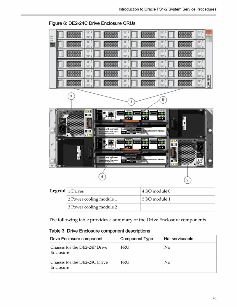
Figure 6: DE2-24C Drive Enclosure CRUs
Legend 1 Drives 4 I/O module 0
2 Power cooling module 1 5 I/O module 1
3 Power cooling module 2
The following table provides a summary of the Drive Enclosure components.
Table 3: Drive Enclosure component descriptionsDrive Enclosure component Component Type Hot serviceable
Chassis for the DE2-24P DriveEnclosure
FRU No
Chassis for the DE2-24C DriveEnclosure
FRU No
Introduction to Oracle FS1-2 System Service Procedures
46

Table 3: Drive Enclosure component descriptions (continued)Drive Enclosure component Component Type Hot serviceable
Two I/O modules (EBOD modules) CRU Yes
Two power cooling modules CRU Yes
Drive Enclosure drives are customer replaceable and hot serviceable. TheOracle FS System release 6.1 supports the following drives:
Note: The list of supported drives can change. Refer to the release notes for yourrelease of the Oracle FS System for the corresponding list of supported drives.
Table 4: Release 6.1 supported drives
Drives and configurations Drive Enclosure type
• 2.5-inch (6.35-cm) SAS-2 small formfactor (SFF) HDDs, 300 GB
• 24 drives in a DE2-24P DriveEnclosure
DE2-24P Drive Enclosure
• 2.5-inch (6.35-cm) SAS-2 SFF HDDs,900 GB
• 24 drives in a DE2-24P DriveEnclosure
DE2-24P Drive Enclosure
• SSDs, 400 GB• Seven or 13 drives in a DE2-24P
Drive Enclosure
DE2-24P Drive Enclosure
• SSDs, 1.6 TB• Seven, 13, or 19 drives in a DE2-24P
Drive Enclosure
DE2-24P Drive Enclosure
• 3.5-inch (8.89-cm) SAS-2 large formfactor (LFF) HDDs, 4 TB
• 24 drives in a DE2-24C DriveEnclosure
DE2-24C Drive Enclosure
Related LinksGuided Maintenance OverviewAccess Guided MaintenanceReplace an I/O ModuleReplace a Drive Enclosure DriveReplace a Power Cooling Module
Introduction to Oracle FS1-2 System Service Procedures
47

Pilot ComponentsWhen replacing a component, you must know its part number and whether it ishot serviceable. Having that information helps you to order the correctreplacement component and to determine whether you can replace thecomponent yourself. To locate a part number for the Pilot, open Oracle SystemHandbook (https://support.oracle.com/handbook_private/index.html) and go tothe Oracle FS1 Flash Storage System components list. Part numbers are listed inthe components list.
The Pilot is a one rack-unit (1U) server and consists of several replaceablecomponents. Many Pilot components are customer replaceable (CRUs), whileothers are field replaceable units (FRUs) that require Oracle Customer Support toperform the replacement. Also, some components are hot-serviceable, meaningthat they can be replaced, while the Pilot is powered on. The following tableprovides a summary of the Pilot FRUs and CRUs.
Table 5: Pilot components and descriptionsPilot component Type Hot-serviceableBattery CRU No
Disk backplane FRU No
8 GB DIMM module CRU No
Cable kit FRU No
CPU FRU No
300 GB SAS HDD FRU No
Fan module CRU No
Note: GM support isrequired to ensurethat failover hasoccurred.
SAS HBA [6 Gb/s] CRU No
Heat sink FRU No
Power supply CRU Yes
The following figure shows the components located at the back of the Pilot.
Figure 7: Pilot back view
Introduction to Oracle FS1-2 System Service Procedures
48
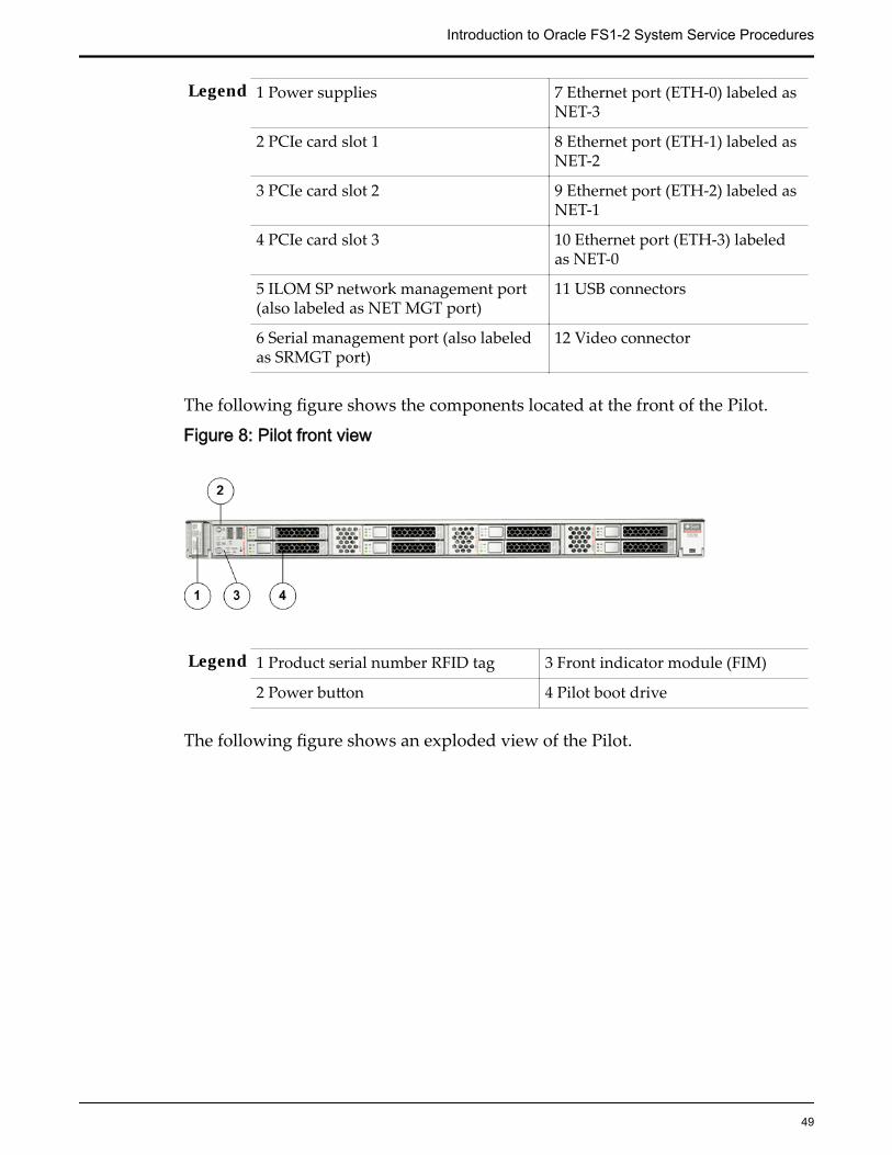
Legend 1 Power supplies 7 Ethernet port (ETH-0) labeled asNET-3
2 PCIe card slot 1 8 Ethernet port (ETH-1) labeled asNET-2
3 PCIe card slot 2 9 Ethernet port (ETH-2) labeled asNET-1
4 PCIe card slot 3 10 Ethernet port (ETH-3) labeledas NET-0
5 ILOM SP network management port(also labeled as NET MGT port)
11 USB connectors
6 Serial management port (also labeledas SRMGT port)
12 Video connector
The following figure shows the components located at the front of the Pilot.
Figure 8: Pilot front view
Legend 1 Product serial number RFID tag 3 Front indicator module (FIM)
2 Power button 4 Pilot boot drive
The following figure shows an exploded view of the Pilot.
Introduction to Oracle FS1-2 System Service Procedures
49

Figure 9: Exploded view of Pilot replaceable components
Legend 1 CPU 7 Battery
2 Motherboard 8 DIMMs
3 Fan modules 9 Heat sinks
4 Fan modules 10 Power supplies
5 HBA 11 Disk backplane boards
6 Risers
Introduction to Oracle FS1-2 System Service Procedures
50

Related LinksReplace a BatteryReplace a ChassisReplace a DIMMReplace a Fan ModuleReplace a Power SupplyReplace a SAS HBAReplace a SAS HDDReplace a CPUReplace a Disk BackplaneReplace a Heat SinkReplace a Motherboard
Warnings and CautionsHazard signal words conform to the American National Standards Institute(ANSI) Z535.4-2002 meanings.
CAUTION: Indicates a potentially hazardous situation that, if not avoided, mayresult in minor or moderate injury.
DANGER: Indicates an imminently hazardous situation that, if not avoided, willresult in death or serious injury.
Tip: To indicate best practices for a process.
Important: To emphasize a point, to remind you of something, or to indicatepotential problems in the outcome of the in-process task.
Electrostatic Discharge PrecautionsCAUTION: Before you handle a component, make sure that you have takenelectrostatic discharge (ESD) precautions:
• The minimum requirement is an anti-static wrist strap connected to a hardground. Remove components from their packaging and place them on anESD-qualified table that is equipped with ground points for wrist straps.
• Static charges can build up rapidly on rolling carts. If you transport ahardware component by cart, ground the cart with a drag chain on an ESDfloor. If there is no ESD cart available or ESD floor, ground yourself beforeyou touch a component that has been transported on a cart.
Required ToolsBefore starting the installation of a Oracle Flash Storage System, be sure you havethe needed equipment and tools available.
Introduction to Oracle FS1-2 System Service Procedures
51

Table 6: Required toolsTool Purpose Illustration#1 and #2 Phillips-headscrewdrivers
Remove and secure OracleFlash Storage Systemhardware components.
Offset box wrench, 13/32inches (10 millimeters)
Work with adjustablemounting rail assemblies.
Torx® T20 screwdriver Attach rail assemblies to thevertical channels and securehardware components to therails.
Torx® T30 screwdriver Connect two racks.
Wire cutters Cut tie wraps.
Note: These tools are not included with the Oracle Flash Storage System.
Guided MaintenanceGuided Maintenance Overview
As a feature of Oracle FS System Manager (GUI), Guided Maintenance presentsyou with a sequence of dialogs that guides you through the process of replacingfield replaceable units (FRUs) and customer replaceable units (CRUs). Promptreplacement of failed FRUs and CRUs helps maintain system reliability.
Guided Maintenance supports the identification and replacement of FRUs andCRUs for Controllers and Drive Enclosures. Guided Maintenance performs thefollowing functions to help you replace FRUs and CRUs:
• Determines the status of the hardware based on events and diagnostics toaccurately reflect the sate of the system.
• Identifies the affected Controller or Drive Enclosure. During the identifyprocess, Guided Maintenance issues a command to light the LEDs on theaffected chassis.
If you are replacing a component on a Drive Enclosure, the following LEDsflash:
Drive Flashes the Locate LED on the Drive Enclosure chassisand the Fault LED on the selected drive.
Power coolingmodule
Flashes the Locate LED on the Drive Enclosure chassisand the Fan Fail LED on the selected power coolingmodule.
I/O module Flashes the Locate LED on the Drive Enclosure chassisand the Fault/Locate LED on the selected I/O module.
Introduction to Oracle FS1-2 System Service Procedures
52

If you are replacing a component on the Controller, the following LEDsflash:
Energy StorageModule (ESM)
Flashes the Locate LED on the front of theController chassis, the Status LED on the back ofthe Controller chassis, and the Ready to RemoveLED on the ESM.
All of the remainingControllercomponents
Flashes the Locate LED on the Controller chassisand the Status LED on the back of the Controllerchassis.
During reverse identify, Guided Maintenance issues a command to lightthe LEDs on all of the chassis except for the affected chassis.
• Prepares the Oracle FS System for component replacement. Duringcomponent preparation, Guided Maintenance issues commands to redirectactivity from a failed component to a redundant component. For FRUs orCRUs that require you to power down a chassis, Guided Maintenanceshuts down the software running on the affected chassis.
• Displays replacement procedures for the failed FRU or CRU. For hot-serviceable FRUs and CRUs, Guided Maintenance presents a sequence ofdialogs with the replacement steps. For FRUs or CRUs that require you topower down a chassis, Guided Maintenance provides a link to HTMLpages containing the replacement steps.
Note: Only administrator accounts set up with support role privileges can accessGuided Maintenance to replace FRUs.
Providing accurate system status and replacing FRUs and CRUs are complexoperations that involve many lower level components within the system. TheOracle FS System is designed to be maintained without requiring support fromthe Oracle Customer Support.
Each FRU and CRU has its own diagnostics, which are called by the Pilot toverify that a FRU or CRU is accessible and functioning properly. The diagnosticsare primarily used to verify FRUs and CRUs that have been added or replaced.The system also tracks parts that have failed and have been removed to preventre-insertion of failed components. Diagnostics run automatically when youreplace a FRU or CRU.
Related LinksAccess Guided MaintenanceReplace an I/O ModuleReplace a Drive Enclosure DriveReplace a Power Cooling ModuleDrive Enclosure ComponentsGuided Maintenance Replaceable Components
Introduction to Oracle FS1-2 System Service Procedures
53

Guided Maintenance Replaceable ComponentsDepending upon the type of component being replaced, Guided Maintenanceprovides different interfaces to help guide you through the replacement process.
Controller and Drive Enclosure Replaceable ComponentsFor hot-serviceable Controller and Drive Enclosure components, GuidedMaintenance presents a sequence of dialogs with the component replacementinstructions. Follow the instructions in Guided Maintenance to replace thefollowing hot-serviceable Controller and Drive Enclosure components:
Table 7: Hot-serviceable components
Controller components Drive Enclosure components
Power supply • Drives• I/O modules• Power cooling modules
For components that require you to initiate failover and power down aController, Guided Maintenance provides a link to HTML pages containing thereplacement instructions. Follow the instructions in the HTML pages to replacethe following components:
• Controller Identification Display
• CPU
• DIMMs
• Energy storage module (ESM)
• ESM backplane
• Fan modules
• HBAs
• Heat sink
• LED Alarm assembly
• Motherboard assembly
• Motherboard cables
• NVDIMMs
• Power distribution board
• Riser
Pilot ComponentsReplacing Pilot components requires assistance from Oracle Customer Support.Oracle Customer Support identifies the failed component for you. You then use
Introduction to Oracle FS1-2 System Service Procedures
54

Guided Maintenance to prepare the Pilots for component replacement. GuidedMaintenance provides a link to Pilot Repair Procedures. Follow the instructions inPilot Repair Procedures to replace the following Pilot components:
Table 8: Pilot replaceable components
Hot serviceable Pilot components Pilot components that require powering down thePilot
Power supply • Battery• CPU• DIMMs• Fan module• Heat sink• Motherboard• Pilot chassis• Pilot disk backplane• Riser• SAS HDD
Related LinksGuided Maintenance OverviewAccess Guided MaintenanceReplace an I/O ModuleReplace a Drive Enclosure DriveReplace a Power Cooling Module
Access Guided MaintenanceUse Oracle FS System Manager (GUI) to access Guided Maintenance.
Prerequisites: If you plan to replace a Controller field replaceable unit (FRU),you must sign into the GUI with an administrator account set upwith Support role privileges.
Related LinksGuided Maintenance OverviewDrive Enclosure ComponentsGuided Maintenance Replaceable Components
Access to Replace a Controller Component (1)For the following Controller components, access Guided Maintenance throughSystem > Hardware.
Introduction to Oracle FS1-2 System Service Procedures
55
• CPUs
• DIMMs
• Energy Storage Modules (ESMs)
• Fan modules
• Motherboard
• NVDIMMs
• Power supplies
1 From Oracle FS System Manager (GUI), navigate to System > Hardware.
2 Select Controllers.The GUI displays the Controllers Overview page. The ControllersOverview pages displays the status of the Controller components.
3 Select the Controller containing the component that is to be replaced.
4 Select Actions > View.The View Controller dialog displays the list of replaceable Controllercomponents in the Replaceable Unit list.
5 From the Replaceable Unit list, select the component that you want toreplace and click Replace Component.Guided Maintenance displays the Introduction page and guides youthrough the steps to replace the Controller component.
Access to Replace a Controller Component (2)For the following Controller components, access Guided Maintenance throughSupport > System Trouble.
• Customer identification display
• ESM backplane
• Heat sink
• LED alarm assembly
• Motherboard cables
• Power distribution board
• PCIe Riser
1 From Oracle FS System Manager (GUI), navigate to Support > SystemTrouble.
2 Select the Controller that contains the component that is to be replaced.
3 Select Actions > Replace Component.Guided Maintenance displays the list of replaceable components for theController.
Introduction to Oracle FS1-2 System Service Procedures
56

Note: Field replaceable units (FRUs) can only be replaced by fieldtechnicians with support role privileges.
4 Select a component from the list.Guided Maintenance displays the Introduction page and guides youthrough the steps to replace the Controller component.
Access to Replace a Drive Enclosure Component1 From Oracle FS System Manager (GUI), navigate to System > Hardware.
2 Select Drive Enclosures.The GUI displays the Drive Enclosures Overview page. The DriveEnclosures Overview page displays the status of the Drive Enclosurecomponents.
3 Select the Drive Enclosure containing the component that you want toreplace.
4 Select Actions > View.The View Drive Enclosure dialog displays the list of replaceable DriveEnclosure components in the Replaceable Unit list.
5 From the Replaceable Unit list, select the component that you want toreplace and click Replace Component.Guided Maintenance displays the Introduction page, and guides youthrough the steps to replace the Drive Enclosure component.
Access to Replace a Pilot Component1 From Oracle FS System Manager (GUI), navigate to System > Hardware.
2 Select Pilots.The GUI displays the Pilots Overview page.
3 Select a Pilot.
4 Select Actions > Repair Pilot.Guided Maintenance displays the Pilot Repair page and guides youthrough the steps to replace a Pilot component.
Introduction to Oracle FS1-2 System Service Procedures
57
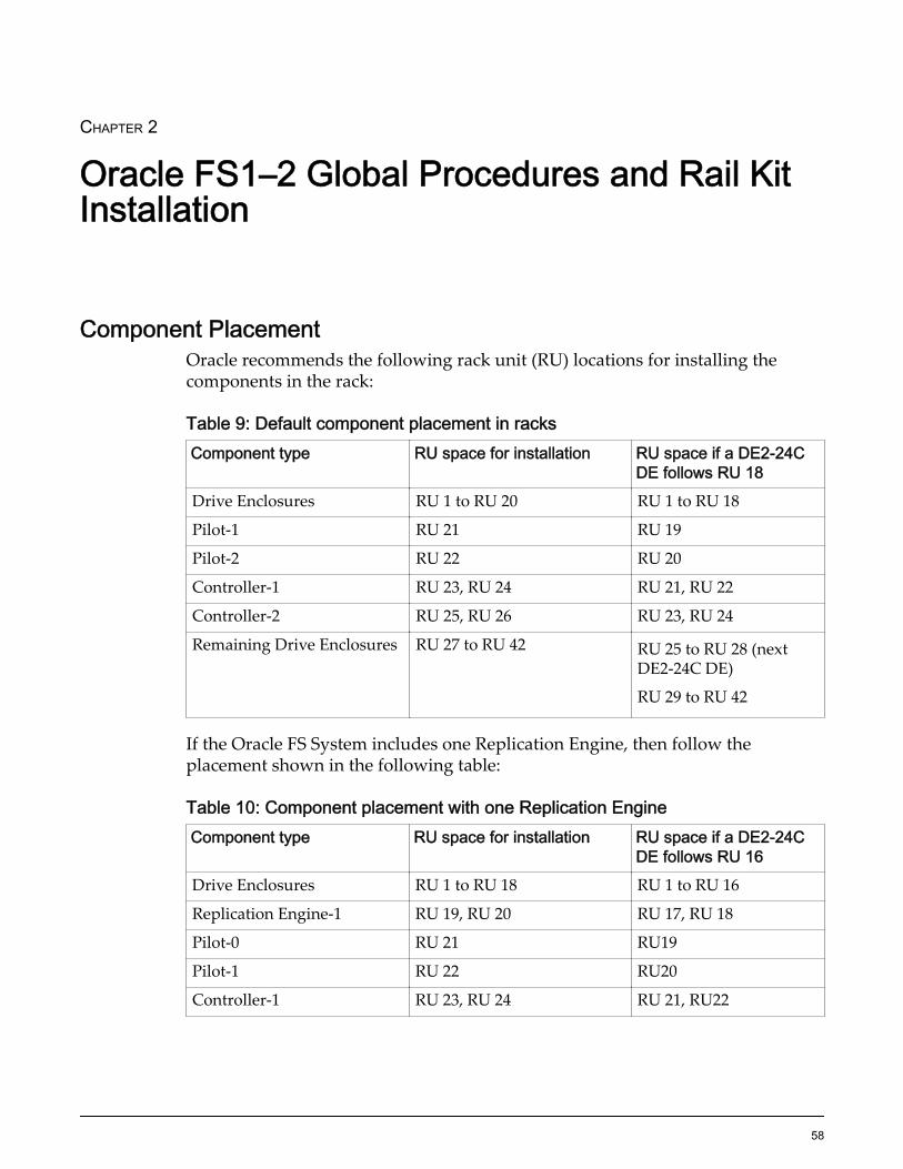
CHAPTER 2
Oracle FS1–2 Global Procedures and Rail KitInstallation
Component PlacementOracle recommends the following rack unit (RU) locations for installing thecomponents in the rack:
Table 9: Default component placement in racksComponent type RU space for installation RU space if a DE2-24C
DE follows RU 18Drive Enclosures RU 1 to RU 20 RU 1 to RU 18
Pilot-1 RU 21 RU 19
Pilot-2 RU 22 RU 20
Controller-1 RU 23, RU 24 RU 21, RU 22
Controller-2 RU 25, RU 26 RU 23, RU 24
Remaining Drive Enclosures RU 27 to RU 42 RU 25 to RU 28 (nextDE2-24C DE)
RU 29 to RU 42
If the Oracle FS System includes one Replication Engine, then follow theplacement shown in the following table:
Table 10: Component placement with one Replication EngineComponent type RU space for installation RU space if a DE2-24C
DE follows RU 16Drive Enclosures RU 1 to RU 18 RU 1 to RU 16
Replication Engine-1 RU 19, RU 20 RU 17, RU 18
Pilot-0 RU 21 RU19
Pilot-1 RU 22 RU20
Controller-1 RU 23, RU 24 RU 21, RU22
58

Table 10: Component placement with one Replication Engine (continued)Component type RU space for installation RU space if a DE2-24C
DE follows RU 16Controller-2 RU 25, RU 26 RU 23, RU 24
Remaining Drive Enclosures RU 27 to RU 42 RU 25 to RU 28 (nextDE2-24C DE)
RU 29 to RU 42
If the Oracle FS System includes two Replication Engines, then follow theplacement shown in the following table:
Table 11: Component placement with two Replication EnginesComponent type RU space for installation RU space if a DE2-24C
DE follows RU 14Drive Enclosures RU 1 to RU 16 RU1 to RU14
Replication Engine-2 RU 17, RU18 RU 15, RU 16
Replication Engine-1 RU 19, RU 20 RU 17, RU18
Pilot-0 RU 21 RU 19
Pilot-1 RU 22 RU 20
Controller-1 RU 23, RU 24 RU 21, RU 22
Controller-2 RU 25, RU 26 RU 23, RU 24
Remaining Drive Enclosures RU 27 to RU 42 RU 25 to RU 28 (nextDE2-24C DE)
RU 29 to RU 42
If the Oracle FS System includes three Replication Engines, then follow theplacement shown in the following table:
Table 12: Component placement with three Replication EnginesComponent type RU space for installation RU space if a DE2-24C
DE follows RU 12Drive Enclosures RU 1 to RU 14 RU 1 to RU 12
Replication Engine-3 RU 15, RU 16 RU 13, RU14
Replication Engine-2 RU 17, RU 18 RU 15, RU 16
Replication Engine-1 RU 19, RU 20 RU 17, RU 18
Pilot-0 RU 21 RU 19
Pilot-1 RU 22 RU 20
Controller-1 RU 23, RU 24 RU 21, RU 22
Oracle FS1–2 Global Procedures and Rail Kit Installation
59

Table 12: Component placement with three Replication Engines (continued)Component type RU space for installation RU space if a DE2-24C
DE follows RU 12Controller-2 RU 25, RU 26 RU 23, RU 24
Remaining Drive Enclosures RU 27 to RU 42 RU 25 to RU 28 (nextDE2-24C DE)
RU 29 to RU 42
If the Oracle FS System includes four Replication Engines, then follow theplacement shown in the following table:
Table 13: Component placement with four Replication EnginesComponent type RU space for installation RU space if a DE2-24C
DE follows RU 10Drive Enclosures RU 1 to RU 12 RU1 to RU10
Replication Engine-4 RU 13, RU 14 RU 11, RU 12
Replication Engine-3 RU 15, RU 16 RU 13, RU 14
Replication Engine-2 RU 17, RU 18 RU 15, RU 16
Replication Engine-1 RU 19, RU 20 RU 17, RU 18
Pilot-0 RU 21 RU 19
Pilot-1 RU 22 RU 20
Controller-1 RU 23, RU 24 RU 21, RU 22
Controller-2 RU 25, RU 26 RU 23, RU 24
Remaining Drive Enclosures RU 27 to RU 42 RU 25 to RU 28 (nextDE2-24C DE)
RU 29 to RU 42
Component NumberingOracle FS Systems support two Pilots (Pilot-1 and Pilot-2). Additionally,Oracle FS Systems support two Controllers (Controller-1 and Controller-2) and 1to 30 Drive Enclosures (DE-1 to DE-30).
The chassis ID number of the Drive Enclosure is based on the order by which theController identifies the Drive Enclosures. Drive Enclosures are also assigned achassis ID number in the Oracle FS System Manager GUI that is labeledEnclosure Chassis ID. The chassis ID number can be changed using the GUI. Thechassis ID number displayed on the chassis must always match the EnclosureChassis ID displayed on the GUI.
Oracle FS1–2 Global Procedures and Rail Kit Installation
60
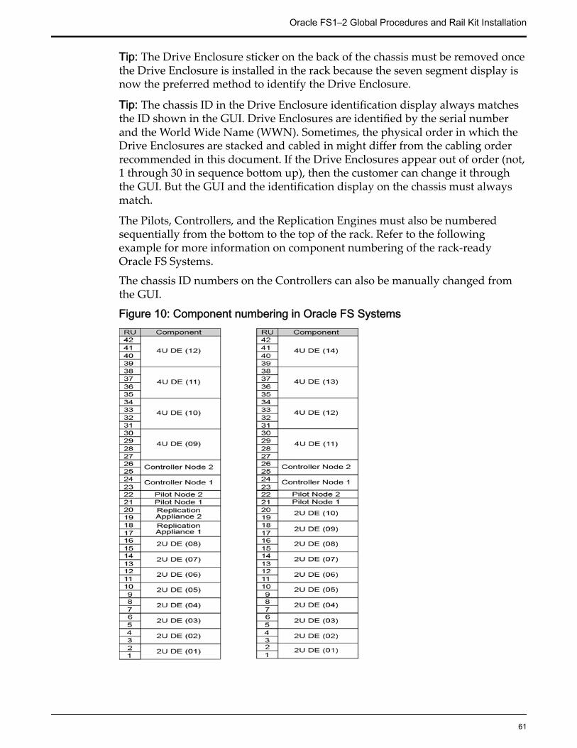
Tip: The Drive Enclosure sticker on the back of the chassis must be removed oncethe Drive Enclosure is installed in the rack because the seven segment display isnow the preferred method to identify the Drive Enclosure.
Tip: The chassis ID in the Drive Enclosure identification display always matchesthe ID shown in the GUI. Drive Enclosures are identified by the serial numberand the World Wide Name (WWN). Sometimes, the physical order in which theDrive Enclosures are stacked and cabled in might differ from the cabling orderrecommended in this document. If the Drive Enclosures appear out of order (not,1 through 30 in sequence bottom up), then the customer can change it throughthe GUI. But the GUI and the identification display on the chassis must alwaysmatch.
The Pilots, Controllers, and the Replication Engines must also be numberedsequentially from the bottom to the top of the rack. Refer to the followingexample for more information on component numbering of the rack-readyOracle FS Systems.
The chassis ID numbers on the Controllers can also be manually changed fromthe GUI.
Figure 10: Component numbering in Oracle FS Systems
Oracle FS1–2 Global Procedures and Rail Kit Installation
61
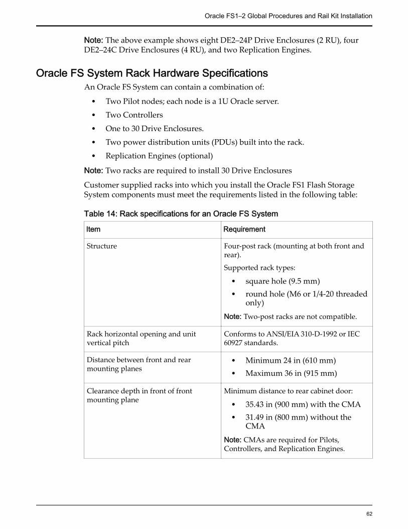
Note: The above example shows eight DE2–24P Drive Enclosures (2 RU), fourDE2–24C Drive Enclosures (4 RU), and two Replication Engines.
Oracle FS System Rack Hardware SpecificationsAn Oracle FS System can contain a combination of:
• Two Pilot nodes; each node is a 1U Oracle server.
• Two Controllers
• One to 30 Drive Enclosures.
• Two power distribution units (PDUs) built into the rack.
• Replication Engines (optional)
Note: Two racks are required to install 30 Drive Enclosures
Customer supplied racks into which you install the Oracle FS1 Flash StorageSystem components must meet the requirements listed in the following table:
Table 14: Rack specifications for an Oracle FS System
Item Requirement
Structure Four-post rack (mounting at both front andrear).
Supported rack types:
• square hole (9.5 mm)• round hole (M6 or 1/4-20 threaded
only)
Note: Two-post racks are not compatible.
Rack horizontal opening and unitvertical pitch
Conforms to ANSI/EIA 310-D-1992 or IEC60927 standards.
Distance between front and rearmounting planes
• Minimum 24 in (610 mm)• Maximum 36 in (915 mm)
Clearance depth in front of frontmounting plane
Minimum distance to rear cabinet door:
• 35.43 in (900 mm) with the CMA• 31.49 in (800 mm) without the
CMA
Note: CMAs are required for Pilots,Controllers, and Replication Engines.
Oracle FS1–2 Global Procedures and Rail Kit Installation
62

Table 14: Rack specifications for an Oracle FS System (continued)
Item Requirement
Clearance width between front and rearmounting planes
Minimum distance between structuralsupports and cable troughs is 18 in (456mm).
Minimum clearance for service access Clearance (front): 48.5 in (123.2 cm)
Clearance (back): 36 in (91 cm)
Front door • Vented
• 1.5 in (3.81 cm) deep
• Lockable
• Open left to right
• 1 in (2.54 cm) clearance between frontvertical channel and inside of frame
Rear door • Vented
• Lockable
• Open left to right
Sides • Solid
• Removable
• Lockable
• 1 inches (2.54 centimeters) betweenside and frame
Vertical channels • 19 in side to side
• 26 in front rail to back rail
Vents • Front and back doors
• Top
PDU • 2 PDUs
• 90–240VAC, 50–60Hz
• 10kVA for single-phase PDUs; 15 kVAfor three-phase PDUs
• 42 outlets (six groups of seven outletseach)
• Vertical mount
Oracle FS1–2 Global Procedures and Rail Kit Installation
63
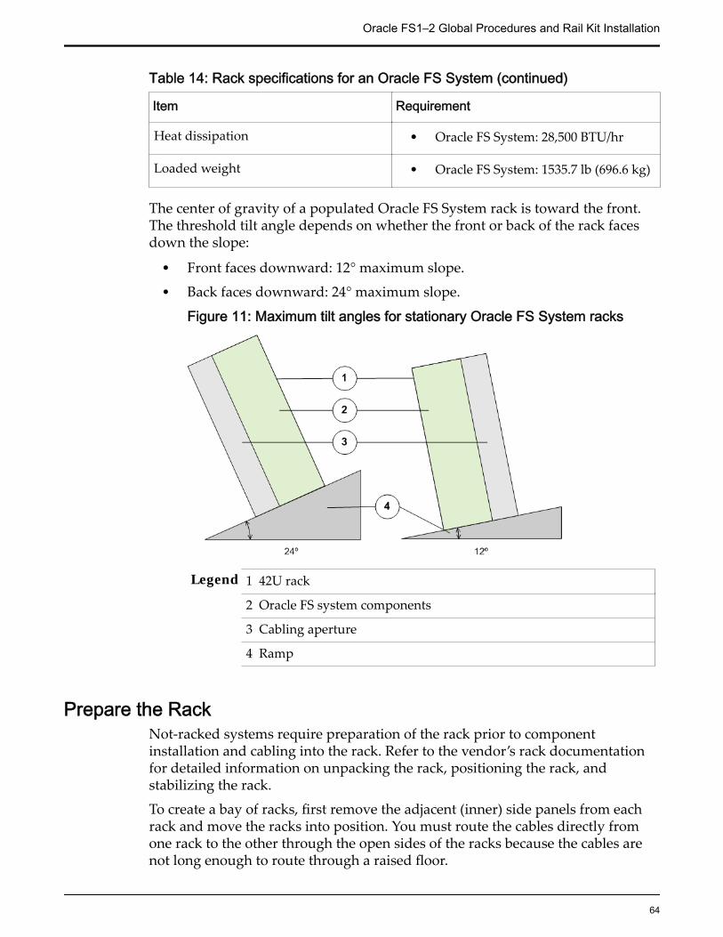
Table 14: Rack specifications for an Oracle FS System (continued)
Item Requirement
Heat dissipation • Oracle FS System: 28,500 BTU/hr
Loaded weight • Oracle FS System: 1535.7 lb (696.6 kg)
The center of gravity of a populated Oracle FS System rack is toward the front.The threshold tilt angle depends on whether the front or back of the rack facesdown the slope:
• Front faces downward: 12° maximum slope.
• Back faces downward: 24° maximum slope.
Figure 11: Maximum tilt angles for stationary Oracle FS System racks
Legend 1 42U rack
2 Oracle FS system components
3 Cabling aperture
4 Ramp
Prepare the RackNot-racked systems require preparation of the rack prior to componentinstallation and cabling into the rack. Refer to the vendor’s rack documentationfor detailed information on unpacking the rack, positioning the rack, andstabilizing the rack.
To create a bay of racks, first remove the adjacent (inner) side panels from eachrack and move the racks into position. You must route the cables directly fromone rack to the other through the open sides of the racks because the cables arenot long enough to route through a raised floor.
Oracle FS1–2 Global Procedures and Rail Kit Installation
64

Remove the Doors From a RackRemove the rack doors to make the placement of the components easier.
1 If locked, unlock the front and back doors of the rack.
2 Release all door hinges, as well as any grounding straps.
Figure 12: Rack door removal
Legend 1 Ground strap
2 Rack door hinge
Note: This is an example of removing the doors from a rack. Your rack maydiffer from the illustration. Consult the rack vendor's documentation fordetails on removing doors and ground straps.
3 Remove the doors and set them aside.
Note: Use care to place the doors where they cannot fall on people or slideand cause injury.
Important: After installing an Oracle FS System, shut all the doors, re-attach theground straps to maintain compliance with applicable emissions requirements.
Remove a Side Panel From a RackYou might be required to remove the rack side panels to have sufficient space toperform service actions such as replace components or cable Drive Enclosures.Consult the rack vendor's documentation for details on how to remove the sidepanels.
Important: Be sure not to pinch any cables that might have strayed from theirproper location.
Oracle FS1–2 Global Procedures and Rail Kit Installation
65

Rack Installation Safety PrecautionsFollow these safety precautions when installing the components in the rack.
CAUTION: If non-Oracle FS System equipment must be installed in the rack,additional care must be taken to ensure that this equipment does not causeoverheating of the Oracle FS System components or block air flow. All Oracle FSSystem components meet these requirements, but ONLY if the installation andrack position guidelines are carefully followed.
CAUTION: Always load components into a rack from the bottom to the top sothat the rack does not become top-heavy and tip over.
CAUTION: Avoid elevated operating ambient temperature. If the component isinstalled in a closed or multi-unit rack assembly, the operating ambienttemperature of the rack environment might be greater than room ambienttemperature. Therefore, make sure that the environment is compatible with themaximum ambient temperature (TMA) specified for the component.
CAUTION: Make sure that there is sufficient amount of airflow required for safeoperation of each component.
CAUTION: Mounting of a component in the rack should be such that ahazardous condition is not created due to uneven mechanical loading.
CAUTION: Consideration should be given to the connection of a component tothe supply circuit and the effect that overloading of the circuits might have onover-current protection and supply wiring. Appropriate consideration ofcomponent nameplate power ratings should be used when addressing thisconcern.
CAUTION: Reliable grounding of rack-mounted equipment should bemaintained. Particular attention should be given to supply connections otherthan direct connections to the branch circuit (for example, use of power strips).
CAUTION: Do not use slide-rail mounted equipment as a shelf.
System-Wide ProceduresData Backups
Regular backups are prudent IT practice. When you service hardwarecomponents that directly affect user data paths, we highly recommend that youfirst back up all user data to external media.
Important: Extraordinary system hardware changes (such as replacing aController) and software configuration changes (such as resetting the system to afactory-fresh state) and all other modifications not specifically mentioned in thisdocument should only be attempted after consultation with Oracle CustomerSupport. A backup of data should always be done prior to all but routinemaintenance actions.
Full system backups to external media must be performed when you want toperform any of the following actions:
Oracle FS1–2 Global Procedures and Rail Kit Installation
66

• Remove a Drive Enclosure permanently from the Oracle FS System.
Note: You need not always perform a complete data backup to removeDrive Enclosures from an Oracle FS System. However, prior to removalmake sure that all necessary resources have been migrated from the DriveEnclosure and the system configuration is not located on the DriveEnclosure. For more information, contact Oracle Customer Support.
• Clear the system configuration. This action removes all user and systemdata.
CAUTION: Before you clear the system configuration, consult with OracleCustomer Support to avoid the risk of losing system configuration data.
To back up the system, refer to the Oracle FS System Oracle Flash Storage SystemNDMP Integration Guide and to the documentation for your NDMP-based backupapplication.
Power CyclingContact Oracle Customer Support before power cycling an Oracle FS Systemexcept in the event of an emergency, in which case, drop all power and thencontact Oracle Customer Support.
Contact Oracle Customer Support before touching any power cables or switches.There are some situations where not power cycling the entire system is thecorrect action.
For failure testing, do not power cycle individual components without firstcontacting Oracle Customer Support.
Controller RailsAdding Controllers in the rack requires you to install rack rails in the rack andslide rails on the chassis for each Controller that you plan to add.
Controller rail kits can be installed in the Sun ™ Rack 900, the Sun Rack 1000, andthird-party ANSI/EIA 310-D-1992 or IEC 60927 compliant racks with thefollowing types of holes:
• Square
• Round
• Threaded
Oracle FS1–2 Global Procedures and Rail Kit Installation
67

Figure 13: Examples of supported rack holes
Legend 1 Square holes
2 Round holes
3 Threaded holes
CAUTION: Oracle recommends that you install each Controller after you installthe rail kit before installing the next combination of rail kit and Controller.Installing all of the rail kits and then inserting the Controllers is not alwayspossible because of potential space limitations at some data centers. Also, yourun the risk of not placing the Controllers in the correct rack position and causingpossible cabling issues.
Note: Controller rails are packaged within the Pilot shipping carton (not theController shipping carton). Ensure that the Controller rails are not misplacedduring unpacking.
Controller Rail KitsThe Controller rail kit contains the following items:
• One slide rail that attaches to the rack posts
• One mounting bracket that attaches to the Controller chassis
• CMA with six pre-installed cable clips
• Package of mounting screws and nuts in assorted sizes to fit various typesof racks and cabinets
• Manufacturer's instruction sheet for the CMA
The following table summarizes the mounting hardware packaged with theController rail kits.
Oracle FS1–2 Global Procedures and Rail Kit Installation
68

Table 15: Controller rail kit mounting screwsContents of the mounting screw packet Quantity Usage
10-32 pan head screw 8 Assemble main andextender sections ofleft and right rails(Typically, left andright rails are shippedpre-assembled)
8-32 pan head screw 4 Mount left and rightrails to front ofcabinet rails
Metric M6 pan head screw 8 • Mount leftand right railsto back ofcabinet rails
• Secure frontof chassis toleft and rightcabinet rails
6–32 flat head screw 2 Secure back of chassisto left and right siderails
Tip: Ensure that you have all of the parts in the Controller rail kit before youbegin the installation of the Controller rails on the rack and the Controllerchassis.Note: To locate part numbers for the rail kits, open Oracle System Handbook(https://support.oracle.com/handbook_private/index.html) and go to theOracle FS1 Flash Storage System components list. Part numbers are listed in thecomponents list.
Install the Rack Rails for the ControllerPrior to adding Controllers, install rails into the rack for each Controller that youplan to add.
Prerequisites: • Ensure that you have adequate room to work around therack while installing the rails and the Controller.
• Attach an electrostatic discharge (ESD) wrist strap to yourwrist, and stand on an ESD mat while replacingcomponents.
Oracle FS1–2 Global Procedures and Rail Kit Installation
69

• Ensure that you have a Phillips Number 2 screwdriverwith at least a four-inch shaft.
• If you are installing the rails in a rack with threaded holes,make sure you have a Torx Number 20 screwdriver.
1 Mark the rack mount hole where you plan to mount the Controller.The Controller requires two standard rack units (2U) of vertical space.
2 Remove the rails from the packaging.
3 Position the front of the left rail behind the left front rack rail.
Figure 14: Controller rack mount location
Legend 1 Rack mount holes
2 Left rail
4 Use a Phillips Number 2 screwdriver to insert and tighten two 8-32panhead screws to secure the left rail to the front of the rack.
Note: Each Controller requires two standard mounting units (2U) ofvertical space in the rack. Each standard mounting unit (U) has threemounting holes in the left and right rack rails.
Note: Insert the screws into the lowest holes in the top two mounting unitsof the 2U slot in which the chassis is to be mounted. These screws passthrough the rack rail holes and screw into threaded holes in the left rail.
Oracle FS1–2 Global Procedures and Rail Kit Installation
70
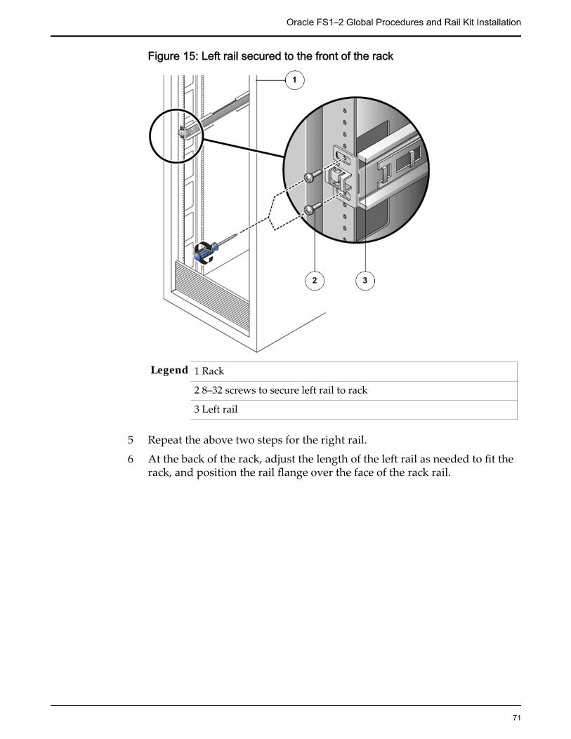
Figure 15: Left rail secured to the front of the rack
Legend 1 Rack
2 8–32 screws to secure left rail to rack
3 Left rail
5 Repeat the above two steps for the right rail.
6 At the back of the rack, adjust the length of the left rail as needed to fit therack, and position the rail flange over the face of the rack rail.
Oracle FS1–2 Global Procedures and Rail Kit Installation
71

Figure 16: Left rail adjusted at the back of the rack
Legend 1 Back of the rack
2 Left rail
7 Align the rail flange so that the mounting holes correspond to those at thefront of the rack.
8 Use a Phillips screwdriver to insert and tighten four metric M6 screws (twoon each side) at the back of the rail.
9 Repeat the above three steps for the right rail.
10 Using a Phillips Number 2 screwdriver, tighten the eight 10-32 panheadadjustment screws (four on each side) toward the back of each rail.
Install the Slide Rails for the Controller1 Extend the mounting brackets completely out of their respective slide rails.
Tip: To extend the mounting brackets out of the slide rails, simultaneouslypress and hold the upper and lower lock buttons of the slide rail lock.Then, pull the mounting bracket out until it locks in the extended position.
Oracle FS1–2 Global Procedures and Rail Kit Installation
72

Figure 17: Slide rail assembly unlocked
Legend 1 Slide rail assembly
2 Slide rail lock button
2 Slide the mounting bracket release button, and then slide the mountingbracket out of the slide rail.
Figure 18: Mounting bracket release button
Legend 1 Slide rail
2 Mounting bracket release button
Oracle FS1–2 Global Procedures and Rail Kit Installation
73

3 Mounting bracket
Figure 19: Slide rail middle section unlocked
Legend 1 Slide rail
2 Metal lever
Tip: Press the metal lever on the middle section of the slide rail to unlockthe slide rail, and then push the middle section back into the rack.
3 Attach a mounting bracket to the right side of the Controller chassis.
Figure 20: Mounting bracket attached to the chassis
Oracle FS1–2 Global Procedures and Rail Kit Installation
74

Legend 1 Mounting bracket
2 Controller chassis
Tip: Position the mounting bracket against the Controller chassis so thatthe mounting bracket are aligned with screw holes and then install thescrews.
4 Attach the second mounting bracket to the left side of the Controllerchassis.
5 Determine which rack hole numbers to use when attaching the slide railsto the rack posts.
Note: The Controller is two rack units tall (2U). The slide rails will occupythe lower half of the 2U space.
6 Determine which screws you will use to mount the slide rails.
Tip: If your rack has threaded mounting holes in the rack posts, determinewhether the threads are metric or standard. Select the appropriate screwsfrom the package included in the mounting kit. If your rack does not havethreaded mounting holes, the mounting screws are secured with a cagednut.
7 Attach a slide rail to the right front rack post.
Figure 21: Slide rail mounted on the rack post
Legend 1 Rack post
2 Slide rail
Oracle FS1–2 Global Procedures and Rail Kit Installation
75

Tip: Loosely attach the front of a slide rail to the right front rack post usingtwo screws but do not tighten the screws yet. Adjust the length of the sliderail by sliding the back mounting flange to reach the outside edge of theback rack post. Loosely attach the back of the slide rail to the back rackpost with two screws.
8 Attach the second slide rail to the left rack posts in a similar manner.
Tip: Do not tighten the screws.
9 Use the slide rail spacing tool to adjust the distance between the slide rails.
Figure 22: Slide rail spacing tool
Legend 1 Spacing tool
2 Slide rails
Tip: At the front of the rack, plug the left side of the tool into slots at theend of the left rail. Insert the right side of the tool into the front end of theright rail, while sliding the end of the rail to the right or left as needed toallow the ends of the tool to enter the ends of both rails. The distancebetween the rails is now equal to the width of the Controller withmounting brackets.
10 Tighten the screws to lock the front ends of the rails in place.
11 Repeat the steps for the back ends of the rails.
12 Deploy the anti-tilt mechanism on the rack, if any.
CAUTION: The weight of the Controller on extended slide rails can beenough to overturn a rack.
13 Insert the ends of the mounting brackets into the sliding rails.
Oracle FS1–2 Global Procedures and Rail Kit Installation
76
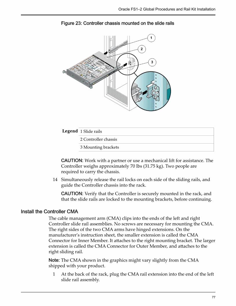
Figure 23: Controller chassis mounted on the slide rails
Legend 1 Slide rails
2 Controller chassis
3 Mounting brackets
CAUTION: Work with a partner or use a mechanical lift for assistance. TheController weighs approximately 70 lbs (31.75 kg). Two people arerequired to carry the chassis.
14 Simultaneously release the rail locks on each side of the sliding rails, andguide the Controller chassis into the rack.
CAUTION: Verify that the Controller is securely mounted in the rack, andthat the slide rails are locked to the mounting brackets, before continuing.
Install the Controller CMAThe cable management arm (CMA) clips into the ends of the left and rightController slide rail assemblies. No screws are necessary for mounting the CMA.The right sides of the two CMA arms have hinged extensions. On themanufacturer's instruction sheet, the smaller extension is called the CMAConnector for Inner Member. It attaches to the right mounting bracket. The largerextension is called the CMA Connector for Outer Member, and attaches to theright sliding rail.
Note: The CMA shown in the graphics might vary slightly from the CMAshipped with your product.
1 At the back of the rack, plug the CMA rail extension into the end of the leftslide rail assembly.
Oracle FS1–2 Global Procedures and Rail Kit Installation
77

Figure 24: CMA rail extension inserted into the back of the left slide rail
Legend 1 CMA rail extension
2 Slide rail
CAUTION: Support the CMA during this installation. Do not allow theassembly to hang by its own weight until it is secured by all threeattachment points.
2 Insert the smaller extension into the clip located at the end of the mountingbracket.
Oracle FS1–2 Global Procedures and Rail Kit Installation
78
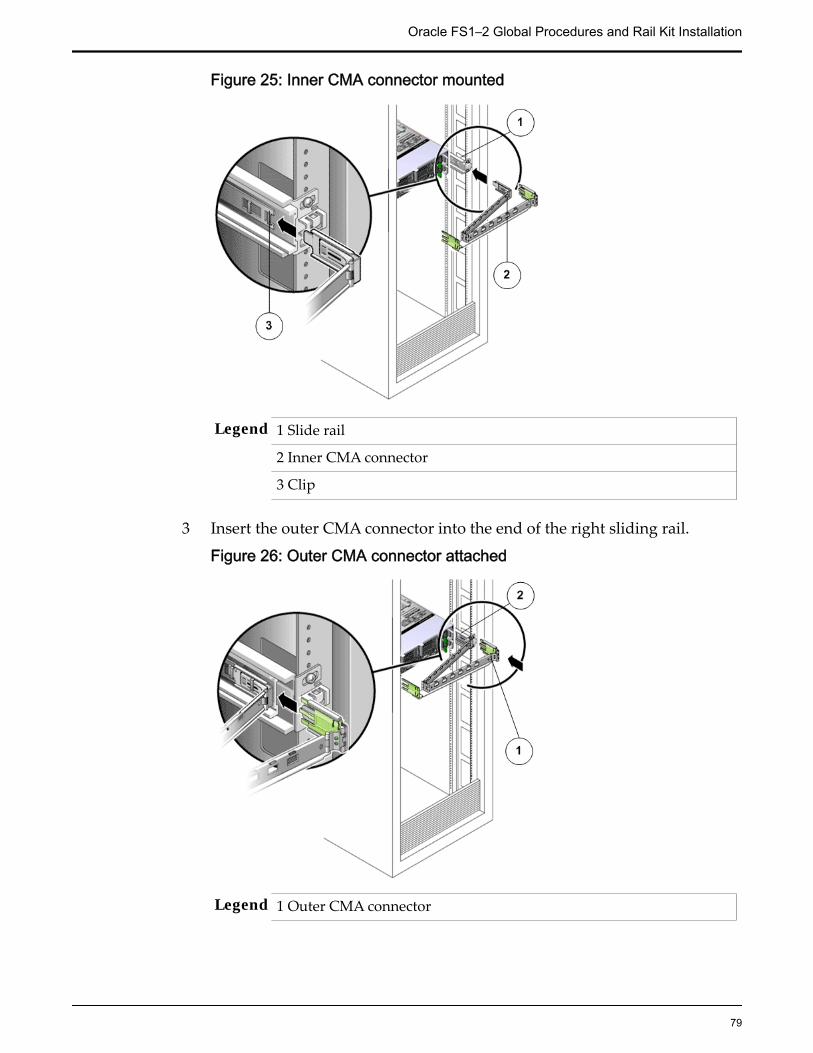
Figure 25: Inner CMA connector mounted
Legend 1 Slide rail
2 Inner CMA connector
3 Clip
3 Insert the outer CMA connector into the end of the right sliding rail.
Figure 26: Outer CMA connector attached
Legend 1 Outer CMA connector
Oracle FS1–2 Global Procedures and Rail Kit Installation
79

2 Slide rail
4 Fully insert the hinged plastic connector at the left side of the CMA into theCMA rail extension.
Figure 27: Left side of the slide rail mounted
Legend 1 Plastic tab on CMA rail extension
2 Slide rail
Insert the Controller Into a RackPrerequisites: Ensure that you have a magnetic-tipped Phillips Number 2
screwdriver with at least a four-inch shank.
CAUTION: Do not power on the Controller until all components have beeninstalled and all internal private management interface (PMI) and privateinterconnect (PI) cables have been connected.
CAUTION: Work with a partner or use a mechanical lift for assistance. TheController weighs approximately 41 lbs (18.59 kg). Two people are required toun-mount and carry the chassis.
CAUTION: Deploy any rack anti-tilt mechanisms before installing the Controllerinto the rack to prevent the rack from tipping over during componentinstallation.
CAUTION: Always load equipment into a rack from the bottom up so that therack will not become top-heavy and tip over.
CAUTION: Slide-rail-mounted components are not to be used as a shelf or a workspace.
Oracle FS1–2 Global Procedures and Rail Kit Installation
80

CAUTION: Elevated operating ambient temperature: If the Controller is installedin a closed or multi-unit rack assembly, the operating ambient temperature of therack environment might be greater than room ambient temperature. Therefore,consideration should be given to installing the components in an environmentcompatible with the maximum ambient temperature (TMA) specified for theController.
1 Using two people, one at each side of the Controller, carefully lift andposition the Controller on the bottom ledge of the left and right rails.
CAUTION: Do not use the power supply handles to lift the chassis. Usingthe power supply handles to lift the chassis can damage the powersupplies and disrupt electrical power to the Controller.
2 Carefully slide the Controller into the rack until the front flanges of theController touch the vertical face of the rack.
3 Use a Phillips screwdriver to install and tighten the four M6 panheadscrews (two on each side) to secure the chassis to the front of the rack.
4 Install and tighten two 6-32 screws (one on each side) at the back of thechassis, to secure the back of the chassis to the rack.
Verify Operation of the Slide Rails and the CMAPrerequisites: • Before handling a component, touch a grounded surface to
discharge any static electricity.• Attach an electrostatic discharge (ESD) wrist strap to your
wrist, and stand on an ESD mat while replacingcomponents.
• Two people are needed to verify the operation of the sliderails and the cable management arm (CMA): one to movethe Controller in and out of the rack and one to observe thecables and CMA.
• To reduce the risk of personal injury, stabilize theexpansion rack cabinet and extend all anti-tilt devicesbefore extending the Controller from the rack.
CAUTION: Work with a partner or use a mechanical lift for assistance. TheController weighs approximately 41 lbs (18.59 kg). Two people are required toun-mount and carry the chassis.
1 Unlock the slide lock buttons at the right and left sides of the Controllerchassis, and slowly pull the Controller out of the rack until the slide railsreach their stops.
Oracle FS1–2 Global Procedures and Rail Kit Installation
81

Figure 28: Controller slide rails unlocked
Legend 1 Slide rail assembly
2 Slide rail lock button
2 Inspect the attached cables for any binding or kinks.
3 Verify that the CMA extends fully and does not bind in the slide rails.
4 When the Controller is fully extended out, release the mounting bracketrelease button.
Figure 29: Mounting bracket release button
Legend 1 Slide rail
Oracle FS1–2 Global Procedures and Rail Kit Installation
82

2 Mounting bracket release button
3 Mounting bracket
5 Slide the Controller back into the rack.6 Simultaneously unlock both slide rail release buttons, and push the
Controller completely into the rack.
Figure 30: Slide rail release button
Legend 1 Slide rail release button
2 Slide rail
Note: The Controller should stop after approximately 15 inches (40 cm) oftravel.
7 Verify that the cables and the CMA retracted without binding.8 Adjust the cable hangers and CMA as required.
Drive Enclosure RailsTo prepare a rack for adding Drive Enclosures to the Oracle Flash StorageSystem, you must install rails in the rack for each Drive Enclosure that you planto add. Oracle includes rail kits in the Drive Enclosure packaging.
Use one of the following racks for the Drive Enclosure:
Oracle FS1–2 Global Procedures and Rail Kit Installation
83
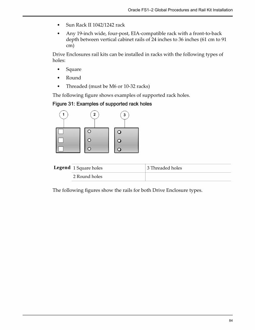
• Sun Rack II 1042/1242 rack
• Any 19-inch wide, four-post, EIA-compatible rack with a front-to-backdepth between vertical cabinet rails of 24 inches to 36 inches (61 cm to 91cm)
Drive Enclosures rail kits can be installed in racks with the following types ofholes:
• Square
• Round
• Threaded (must be M6 or 10-32 racks)
The following figure shows examples of supported rack holes.
Figure 31: Examples of supported rack holes
Legend 1 Square holes 3 Threaded holes
2 Round holes
The following figures show the rails for both Drive Enclosure types.
Oracle FS1–2 Global Procedures and Rail Kit Installation
84
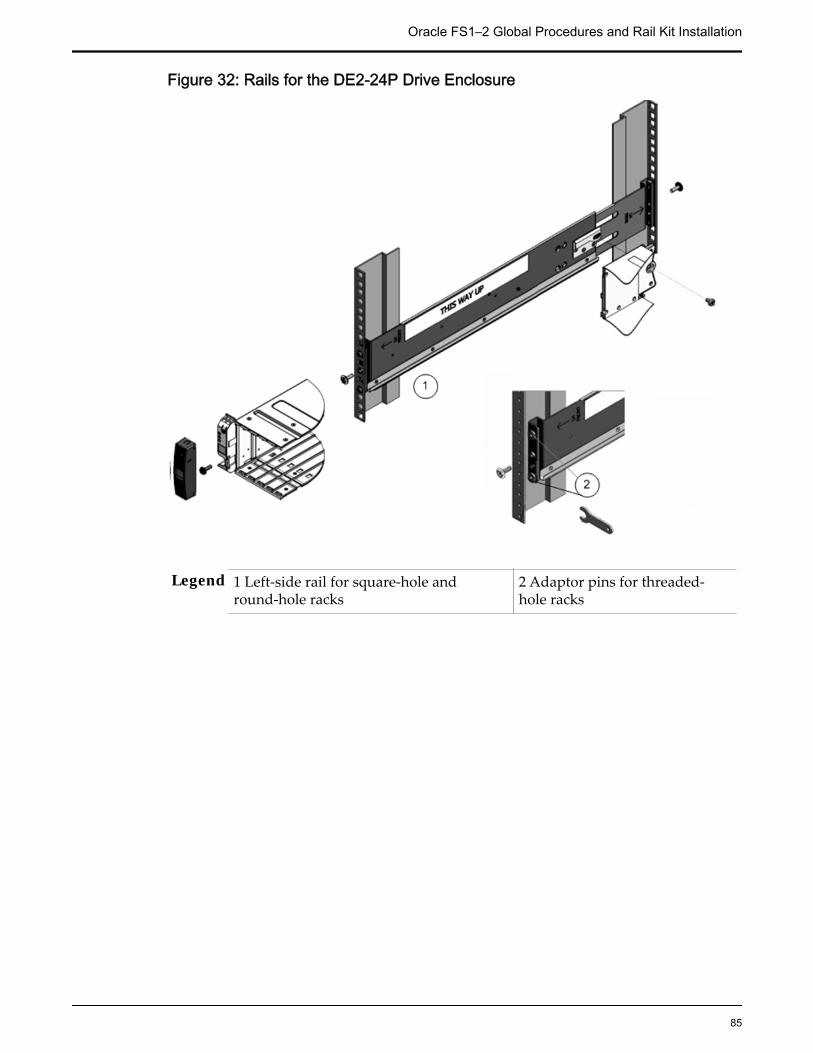
Figure 32: Rails for the DE2-24P Drive Enclosure
Legend 1 Left-side rail for square-hole andround-hole racks
2 Adaptor pins for threaded-hole racks
Oracle FS1–2 Global Procedures and Rail Kit Installation
85

Figure 33: Rails for the DE2-24C Drive Enclosure
Legend 1 Left-side rail for square-hole racks 3 Round-hole racks
2 Threaded-hole racks
Drive Enclosure Rail KitsThe following table summarizes the contents of the Drive Enclosure rail kits.
Oracle FS1–2 Global Procedures and Rail Kit Installation
86
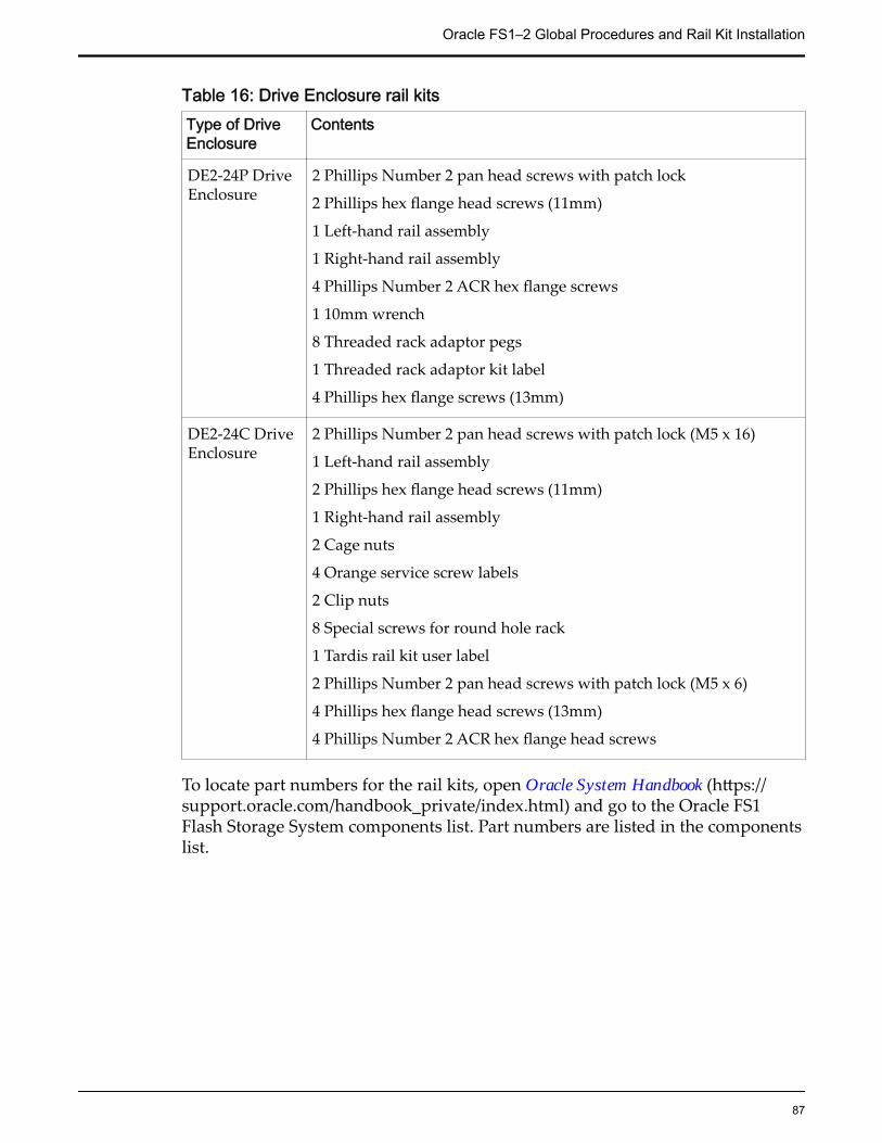
Table 16: Drive Enclosure rail kitsType of DriveEnclosure
Contents
DE2-24P DriveEnclosure
2 Phillips Number 2 pan head screws with patch lock
2 Phillips hex flange head screws (11mm)
1 Left-hand rail assembly
1 Right-hand rail assembly
4 Phillips Number 2 ACR hex flange screws
1 10mm wrench
8 Threaded rack adaptor pegs
1 Threaded rack adaptor kit label
4 Phillips hex flange screws (13mm)
DE2-24C DriveEnclosure
2 Phillips Number 2 pan head screws with patch lock (M5 x 16)
1 Left-hand rail assembly
2 Phillips hex flange head screws (11mm)
1 Right-hand rail assembly
2 Cage nuts
4 Orange service screw labels
2 Clip nuts
8 Special screws for round hole rack
1 Tardis rail kit user label
2 Phillips Number 2 pan head screws with patch lock (M5 x 6)
4 Phillips hex flange head screws (13mm)
4 Phillips Number 2 ACR hex flange head screws
To locate part numbers for the rail kits, open Oracle System Handbook (https://support.oracle.com/handbook_private/index.html) and go to the Oracle FS1Flash Storage System components list. Part numbers are listed in the componentslist.
Oracle FS1–2 Global Procedures and Rail Kit Installation
87

Install Drive Enclosure RailsPrior to adding Drive Enclosures, install rails into the rack for each DriveEnclosure that you plan to add.
Prerequisites: • Before handling a component, touch a grounded surface todischarge any static electricity.
• Attach an electrostatic discharge (ESD) wrist strap to yourwrist, and stand on an ESD mat while replacingcomponents.
• Ensure that you have a Phillips Number 2 screwdriverwith at least a four-inch shaft.
• If you are installing the rails in a rack with threaded holes,make sure you have a Torx Number 20 screwdriver.
• Ensure that you have a flashlight to use when verifyingthat the Drive Enclosure is seated in the rack.
Install Rails for DE2-24P Drive EnclosuresThe rails for the DE2-24P Drive Enclosure are preassembled with rail-locationpegs on the front and back for installation in a square hole rack and a round holerack. If you install the rails in a threaded, universal 19-inch rack, you mustreplace the rail-location pegs with adaptor pins before installing the rails in therack.
Note: To simplify the following procedures, install the left-side rail assembly firstand then the right-side rail assembly.
Install Rails in Threaded Racks1 Use a Torx Number 20 screwdriver to remove the rail-location pegs from
the front and back of the rails.
2 Use a 10mm wrench to insert the adaptor pins into the ends of the railswhere you removed the rail-location pegs.
A 10mm wrench and adaptor pins are included in the rail kit packaging.
Oracle FS1–2 Global Procedures and Rail Kit Installation
88

Figure 34: 10mm wrench and adaptor pins
Legend 1 10mm wrench 2 Adaptor pins
3 Position the front of the rails inside of the rack, with the rail flange insideof the rack flange.
The rail label faces the inside of the rack. The pins should be fully locatedwithin the rack holes.
Oracle FS1–2 Global Procedures and Rail Kit Installation
89
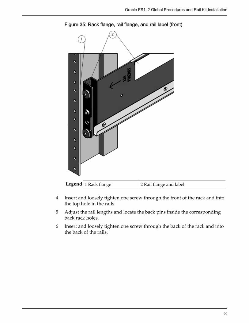
Figure 35: Rack flange, rail flange, and rail label (front)
Legend 1 Rack flange 2 Rail flange and label
4 Insert and loosely tighten one screw through the front of the rack and intothe top hole in the rails.
5 Adjust the rail lengths and locate the back pins inside the correspondingback rack holes.
6 Insert and loosely tighten one screw through the back of the rack and intothe back of the rails.
Oracle FS1–2 Global Procedures and Rail Kit Installation
90
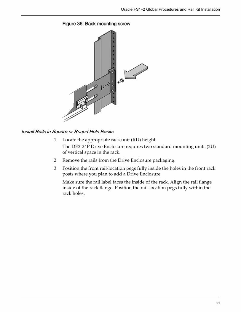
Figure 36: Back-mounting screw
Install Rails in Square or Round Hole Racks1 Locate the appropriate rack unit (RU) height.
The DE2-24P Drive Enclosure requires two standard mounting units (2U)of vertical space in the rack.
2 Remove the rails from the Drive Enclosure packaging.
3 Position the front rail-location pegs fully inside the holes in the front rackposts where you plan to add a Drive Enclosure.
Make sure the rail label faces the inside of the rack. Align the rail flangeinside of the rack flange. Position the rail-location pegs fully within therack holes.
Oracle FS1–2 Global Procedures and Rail Kit Installation
91

Figure 37: Front of the rack and rail-location pegs
Legend 1 Rail-location pegs 2 Front rack post
4 Insert and tighten one Phillips 13mm head hex flange screw through thefront rack hole and into the top hole of the rail.
Oracle FS1–2 Global Procedures and Rail Kit Installation
92

Figure 38: A Phillips 13mm head hex flange screw and the front of a rack
Legend 1 Phillips 13mm head hex flange screw 2 Rail-location pegs
5 From the back of the rack, position the pegs fully into the correspondingrack holes.To position the pegs, extend the length of the rail to the back of the rackand position the pegs through the appropriate rack holes.
Figure 39: Extended rail to the back of the rack
Legend 1 Back of the rack
Oracle FS1–2 Global Procedures and Rail Kit Installation
93

6 Insert and tighten one Phillips 13mm head hex flange screw into the backof the rack and into the rail.
Figure 40: A Phillips 13mm head hex flange screw and the back of a rack
7 Repeat steps 1-6 to install the right-hand rail assembly.
Install Rails for DE2-24C Drive Enclosures1 Locate the appropriate rack unit (RU) height.
The DE2-24C Drive Enclosure requires four standard rack units (4U) ofvertical space.
2 Remove the rails from the Drive Enclosure packaging.
3 If you are installing rails in a square-hole rack, snap one cage nut into theeighth rack hole on both sides of the rack.
To locate the eighth rack hole, count eight holes upward from the bottomrail location peg.
The following figure shows a cage nut installed in a square-hole rack.
Oracle FS1–2 Global Procedures and Rail Kit Installation
94
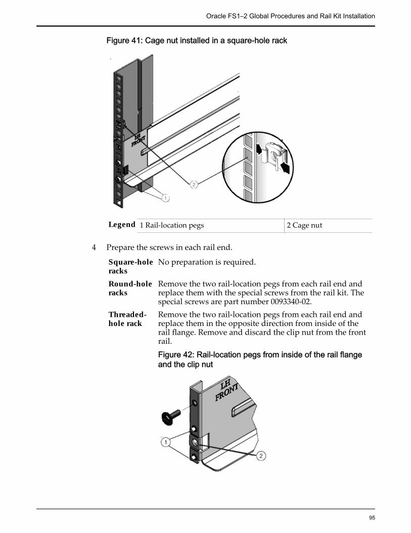
Figure 41: Cage nut installed in a square-hole rack
Legend 1 Rail-location pegs 2 Cage nut
4 Prepare the screws in each rail end.
Square-holeracks
No preparation is required.
Round-holeracks
Remove the two rail-location pegs from each rail end andreplace them with the special screws from the rail kit. Thespecial screws are part number 0093340-02.
Threaded-hole rack
Remove the two rail-location pegs from each rail end andreplace them in the opposite direction from inside of therail flange. Remove and discard the clip nut from the frontrail.
Figure 42: Rail-location pegs from inside of the rail flangeand the clip nut
Oracle FS1–2 Global Procedures and Rail Kit Installation
95

Legend 1 Rail location pegs from inside ofthe rail flange
2 Clip nut
5 Position the front of the rails inside of the rack.
Make sure the rail flange aligns with the inside of the rack flange and therail label faces the inside of the rack.
Square-hole racks The rail-location pegs fit inside of the rack holes.Round-hole rack The special screws fit inside of the rack holes.Threaded-hole rack The rail-location pegs fit inside of the rack holes.
The following figure shows an example of the rail-location pegs insertedinto a square-hole rack.
Figure 43: Rail-location pegs and a square-hole rack
Legend 1 Rail-location pegs 2 Cage nut
6 Extend the rail length towards the back of the rack and into the rail holes atthe back of the rack.
Oracle FS1–2 Global Procedures and Rail Kit Installation
96

Figure 44: Rail extended to holes in the back of the rack
7 Insert and fully tighten one Phillips 13mm head hex flange screw throughthe back of the rack and into the rail.
8 Tighten the two locking screws in the side of the rail.
Figure 45: The locking screws and side of the rail
9 Repeat steps 1 - 8 to install the right-hand rail assembly.
Oracle FS1–2 Global Procedures and Rail Kit Installation
97

Insert a DE2-24P Drive Enclosure Into a Rack1 With the help of a partner or mechanical lift, carefully lift the Drive
Enclosure to the location of the prepared slot and rest the Drive Enclosureon the bottom ledge of the left and right rails.
CAUTION: The Drive Enclosures are heavy. Work with a partner or use amechanical lift for assistance. The DE2-24C Drive Enclosure weighsapproximately 102 lbs (46 kg) and the DE2-24P Drive Enclosure weighsapproximately 53 lbs (24 kg). Be careful not to drop a Drive Enclosure.Dropping a Drive Enclosure can cause damage and can reduce the life ofthe drives.
CAUTION: Do not use the power supply handles to lift the chassis. Usingthe power supply handles to lift the chassis can damage the power coolingmodules and disrupt electrical power to the Drive Enclosure.
Figure 46: DE2-24P Drive Enclosure (left) and DE2-24C Drive Enclosure(right)
2 Angle the Drive Enclosure slightly to the left and align the DriveEnclosure’s left side slider so that it engages with the left rail channel.
Figure 47: Left rail channel
Oracle FS1–2 Global Procedures and Rail Kit Installation
98
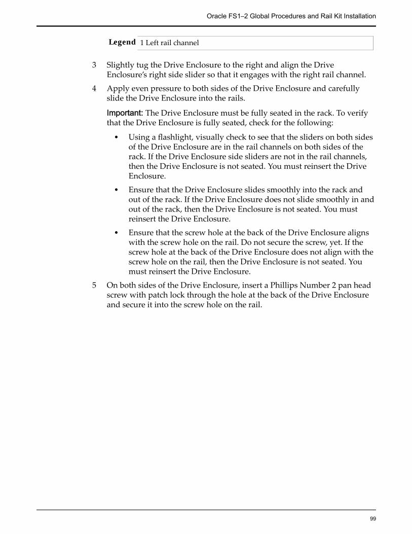
Legend 1 Left rail channel
3 Slightly tug the Drive Enclosure to the right and align the DriveEnclosure’s right side slider so that it engages with the right rail channel.
4 Apply even pressure to both sides of the Drive Enclosure and carefullyslide the Drive Enclosure into the rails.
Important: The Drive Enclosure must be fully seated in the rack. To verifythat the Drive Enclosure is fully seated, check for the following:
• Using a flashlight, visually check to see that the sliders on both sidesof the Drive Enclosure are in the rail channels on both sides of therack. If the Drive Enclosure side sliders are not in the rail channels,then the Drive Enclosure is not seated. You must reinsert the DriveEnclosure.
• Ensure that the Drive Enclosure slides smoothly into the rack andout of the rack. If the Drive Enclosure does not slide smoothly in andout of the rack, then the Drive Enclosure is not seated. You mustreinsert the Drive Enclosure.
• Ensure that the screw hole at the back of the Drive Enclosure alignswith the screw hole on the rail. Do not secure the screw, yet. If thescrew hole at the back of the Drive Enclosure does not align with thescrew hole on the rail, then the Drive Enclosure is not seated. Youmust reinsert the Drive Enclosure.
5 On both sides of the Drive Enclosure, insert a Phillips Number 2 pan headscrew with patch lock through the hole at the back of the Drive Enclosureand secure it into the screw hole on the rail.
Oracle FS1–2 Global Procedures and Rail Kit Installation
99

Figure 48: Back of the Drive Enclosure and Rail secured
Legend 1 Phillips Number 2 pan head screwwith patch lock
2 Back of the DriveEnclosure
Important: If you insert the screw through the hole at the back of the DriveEnclosure and the screw does not align with the screw hole on the rail,then the Drive Enclosure is not seated. You must reinstall the DriveEnclosure.
6 Remove the front-side caps on both sides of the Drive Enclosure and securea Phillips 13mm head hex flange screw.
Note: The front-side cap on the right side of the Drive Enclosure containsthe RFID tag, which uniquely identifies the Drive Enclosure. Take care notto mix up the right front-side caps among Drive Enclosures.
Oracle FS1–2 Global Procedures and Rail Kit Installation
100

Figure 49: Left front-side cap and Phillips 13mm head hex flange screw
Legend 1 Phillips 13mm head hex flange screw 2 Left front-side cap
After you have secured the Drive Enclosure to the rails, attach the front-side caps to the Drive Enclosure.
7 Insert the I/O modules, the power cooling modules, and all of the drivesinto their corresponding slots in the chassis.
Insert a DE2-24C Drive Enclosure Into a Rack1 With the help of a partner or mechanical lift, carefully lift the Drive
Enclosure to the location of the prepared slot and rest the Drive Enclosureon the bottom ledge of the left and right rails.
CAUTION: The Drive Enclosures are heavy. Work with a partner or use amechanical lift for assistance. The DE2-24C Drive Enclosure weighsapproximately 102 lbs (46 kg) and the DE2-24P Drive Enclosure weighsapproximately 53 lbs (24 kg). Be careful not to drop a Drive Enclosure.Dropping a Drive Enclosure can cause damage and can reduce the life ofthe drives.
CAUTION: Do not use the power supply handles to lift the chassis. Usingthe power supply handles to lift the chassis can damage the power coolingmodules and disrupt electrical power to the Drive Enclosure.
Oracle FS1–2 Global Procedures and Rail Kit Installation
101

Figure 50: DE2-24P Drive Enclosure (left) and DE2-24C Drive Enclosure(right)
2 Carefully slide the Drive Enclosure into the rack.
The DE2-24C Drive Enclosure rails have a ledge along the bottom of therail to allow you to slide the Drive Enclosure into the rack. To verify thatthe Drive Enclosure is seated correctly in the rails, ensure that the bottomedges on both sides of the Drive Enclosure slide along the left and right railledges.
Figure 51: The rail ledge for the DE2-24C Drive Enclosure
3 At the back of the chassis, insert and fully tighten a Phillips Number 2 panhead screw with patch lock into the side of the rail.
Oracle FS1–2 Global Procedures and Rail Kit Installation
102
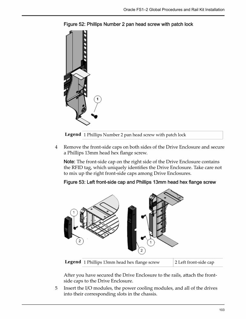
Figure 52: Phillips Number 2 pan head screw with patch lock
Legend 1 Phillips Number 2 pan head screw with patch lock
4 Remove the front-side caps on both sides of the Drive Enclosure and securea Phillips 13mm head hex flange screw.
Note: The front-side cap on the right side of the Drive Enclosure containsthe RFID tag, which uniquely identifies the Drive Enclosure. Take care notto mix up the right front-side caps among Drive Enclosures.
Figure 53: Left front-side cap and Phillips 13mm head hex flange screw
Legend 1 Phillips 13mm head hex flange screw 2 Left front-side cap
After you have secured the Drive Enclosure to the rails, attach the front-side caps to the Drive Enclosure.
5 Insert the I/O modules, the power cooling modules, and all of the drivesinto their corresponding slots in the chassis.
Oracle FS1–2 Global Procedures and Rail Kit Installation
103

Pilot RailsAdding Pilots in the rack requires you to install rack rails in the rack and sliderails on the chassis for each Pilot that you plan to add.
Pilot rail kits can be installed in the Sun trademark Rack 900, the Sun Rack 1000,and third-party ANSI/EIA 310-D-1992 or IEC 60927 compliant racks with thefollowing types of holes:
• Square (9.5 mm)
• Round (M6 or 1/4-20 threaded only)
CAUTION: We recommend that you install each Pilot after you install the rail kitbefore installing the next combination of rail kit and Pilot. Installing all of the railkits and then inserting the Pilots is not always possible because of potential spacelimitations in some data centers. Also, you run the risk of not placing the Pilot inthe correct rack position and causing possible cabling issues.
Pilot Rail KitsThe Pilot rail kit contains the following items:
• One slide rail that attaches to the rack posts
• One mounting bracket that attaches to the Pilot chassis
• CMA with six pre-installed cable clips
• Four M4 x 5 fine-pitch mounting bracket securing screws (optional)
• Manufacturer's instruction sheet
Tip: Ensure that you have all of the parts in the Pilot rail kit before you begin theinstallation of the Pilot rails on the rack and the Pilot chassis.Note: To locate part numbers for the rail kits, open Oracle System Handbook(https://support.oracle.com/handbook_private/index.html) and go to theOracle FS1 Flash Storage System components list. Part numbers are listed in thecomponents list.
The following figure shows the parts in the Pilot rail kit.
Oracle FS1–2 Global Procedures and Rail Kit Installation
104
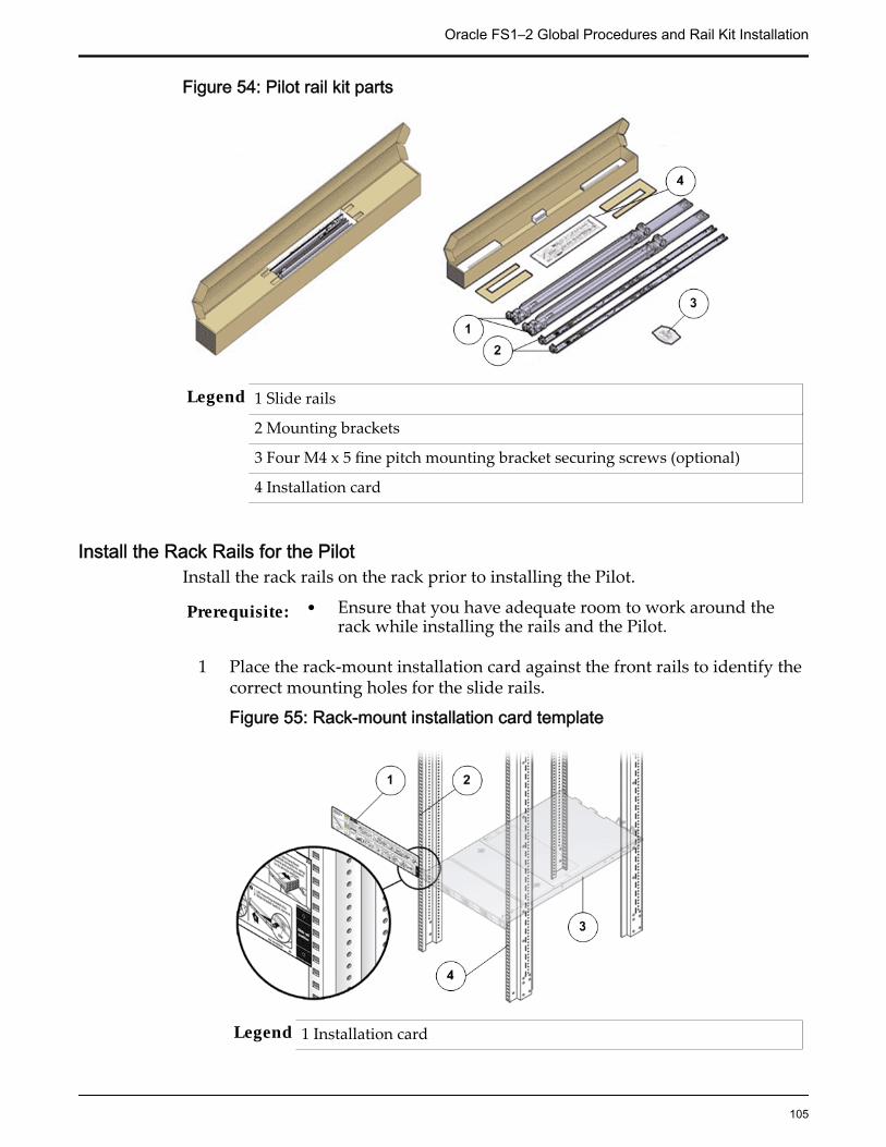
Figure 54: Pilot rail kit parts
Legend 1 Slide rails
2 Mounting brackets
3 Four M4 x 5 fine pitch mounting bracket securing screws (optional)
4 Installation card
Install the Rack Rails for the PilotInstall the rack rails on the rack prior to installing the Pilot.
Prerequisite: • Ensure that you have adequate room to work around therack while installing the rails and the Pilot.
1 Place the rack-mount installation card against the front rails to identify thecorrect mounting holes for the slide rails.
Figure 55: Rack-mount installation card template
Legend 1 Installation card
Oracle FS1–2 Global Procedures and Rail Kit Installation
105

2 Rack mount hole
3 Pilot chassis
4 Front rack post
Note: The Pilot requires one standard rack units (1U) of vertical space.
Tip: The bottom edge of the installation card must correspond to thebottom edge of the Pilot. Measure up from the bottom of the installationcard.
2 Mark the mounting holes for the front slide rails.
3 Mark the mounting holes for the back slide rails.
4 Remove the rails from the packaging.
5 Orient the slide-rail assembly so that the ball bearing track is forward andlocked in place.
Figure 56: Slide rails oriented with the ball bearing track
Legend 1 Slide rail
2 Ball bearing track
3 Locking mechanism
6 Starting with either the left or right side of the rack, align the rear of theslide-rail assembly against the inside of the rear rack rail, and push untilthe assembly locks into place with an audible click.
Oracle FS1–2 Global Procedures and Rail Kit Installation
106

Figure 57: Slide rail assembly aligned with the rack
Legend 1 Back of the rack
2 Slide rail
7 Align the front of the slide-rail assembly against the outside of the frontrack rail, and push until the assembly locks into place with an audibleclick.
8 Repeat steps to attach the slide-rail assembly to the other side of the rack.
Install the Slide Rails for the PilotInstall the slide rails with mounting brackets on to the Pilot chassis beforeinserting it into the rack.
1 Position a mounting bracket against the Pilot chassis so that the slide raillock is at the Pilot front, and the five keyhole openings on the mountingbracket are aligned with the five locating pins on the side of the Pilotchassis.
Oracle FS1–2 Global Procedures and Rail Kit Installation
107
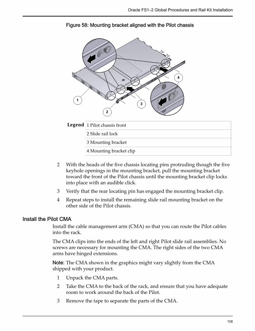
Figure 58: Mounting bracket aligned with the Pilot chassis
Legend 1 Pilot chassis front
2 Slide rail lock
3 Mounting bracket
4 Mounting bracket clip
2 With the heads of the five chassis locating pins protruding though the fivekeyhole openings in the mounting bracket, pull the mounting brackettoward the front of the Pilot chassis until the mounting bracket clip locksinto place with an audible click.
3 Verify that the rear locating pin has engaged the mounting bracket clip.
4 Repeat steps to install the remaining slide rail mounting bracket on theother side of the Pilot chassis.
Install the Pilot CMAInstall the cable management arm (CMA) so that you can route the Pilot cablesinto the rack.
The CMA clips into the ends of the left and right Pilot slide rail assemblies. Noscrews are necessary for mounting the CMA. The right sides of the two CMAarms have hinged extensions.
Note: The CMA shown in the graphics might vary slightly from the CMAshipped with your product.
1 Unpack the CMA parts.
2 Take the CMA to the back of the rack, and ensure that you have adequateroom to work around the back of the Pilot.
3 Remove the tape to separate the parts of the CMA.
Oracle FS1–2 Global Procedures and Rail Kit Installation
108

4 Insert the CMA’s mounting bracket connector into the back of the rightslide rail until the connector locks into place with an audible click.
5 Insert the right CMA slide rail connector into the back of the right slide railassembly until the connector locks into place with an audible click.
Figure 59: CMA slide rail connector inserted into the back of the right sliderail
Legend 1 CMA slide rail connector
2 Right slide rail
Note: The CMA in the graphic is for representation only. The CMAshipped with your Pilot might be slightly different.
6 Insert the left CMA slide-rail connector into the back of the left slide railassembly until the connector locks into place with an audible click.
Oracle FS1–2 Global Procedures and Rail Kit Installation
109
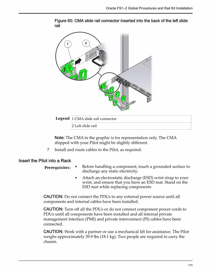
Figure 60: CMA slide rail connector inserted into the back of the left sliderail
Legend 1 CMA slide rail connector
2 Left slide rail
Note: The CMA in the graphic is for representation only. The CMAshipped with your Pilot might be slightly different.
7 Install and route cables to the Pilot, as required.
Insert the Pilot into a RackPrerequisites: • Before handling a component, touch a grounded surface to
discharge any static electricity.• Attach an electrostatic discharge (ESD) wrist strap to your
wrist, and ensure that you have an ESD mat. Stand on theESD mat while replacing components
CAUTION: Do not connect the PDUs to any external power source until allcomponents and internal cables have been installed.
CAUTION: Turn off all the PDUs or do not connect component power cords toPDUs until all components have been installed and all internal privatemanagement interface (PMI) and private interconnect (PI) cables have beenconnected.
CAUTION: Work with a partner or use a mechanical lift for assistance. The Pilotweighs approximately 39.9 lbs (18.1 kg). Two people are required to carry thechassis.
Oracle FS1–2 Global Procedures and Rail Kit Installation
110
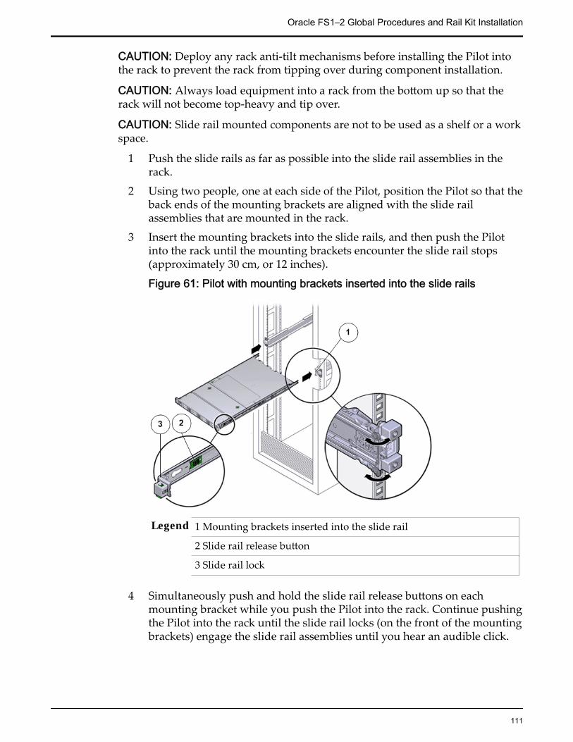
CAUTION: Deploy any rack anti-tilt mechanisms before installing the Pilot intothe rack to prevent the rack from tipping over during component installation.
CAUTION: Always load equipment into a rack from the bottom up so that therack will not become top-heavy and tip over.
CAUTION: Slide rail mounted components are not to be used as a shelf or a workspace.
1 Push the slide rails as far as possible into the slide rail assemblies in therack.
2 Using two people, one at each side of the Pilot, position the Pilot so that theback ends of the mounting brackets are aligned with the slide railassemblies that are mounted in the rack.
3 Insert the mounting brackets into the slide rails, and then push the Pilotinto the rack until the mounting brackets encounter the slide rail stops(approximately 30 cm, or 12 inches).
Figure 61: Pilot with mounting brackets inserted into the slide rails
Legend 1 Mounting brackets inserted into the slide rail
2 Slide rail release button
3 Slide rail lock
4 Simultaneously push and hold the slide rail release buttons on eachmounting bracket while you push the Pilot into the rack. Continue pushingthe Pilot into the rack until the slide rail locks (on the front of the mountingbrackets) engage the slide rail assemblies until you hear an audible click.
Oracle FS1–2 Global Procedures and Rail Kit Installation
111
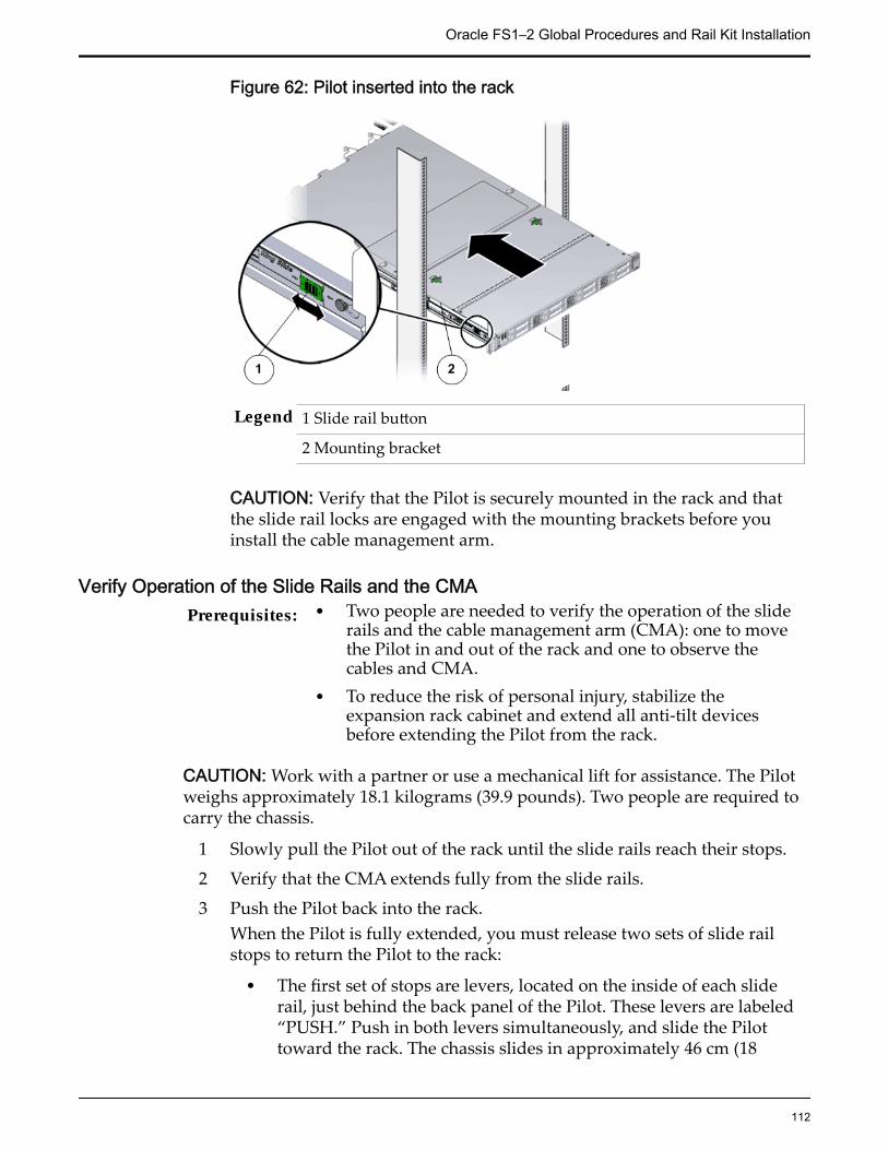
Figure 62: Pilot inserted into the rack
Legend 1 Slide rail button
2 Mounting bracket
CAUTION: Verify that the Pilot is securely mounted in the rack and thatthe slide rail locks are engaged with the mounting brackets before youinstall the cable management arm.
Verify Operation of the Slide Rails and the CMAPrerequisites: • Two people are needed to verify the operation of the slide
rails and the cable management arm (CMA): one to movethe Pilot in and out of the rack and one to observe thecables and CMA.
• To reduce the risk of personal injury, stabilize theexpansion rack cabinet and extend all anti-tilt devicesbefore extending the Pilot from the rack.
CAUTION: Work with a partner or use a mechanical lift for assistance. The Pilotweighs approximately 18.1 kilograms (39.9 pounds). Two people are required tocarry the chassis.
1 Slowly pull the Pilot out of the rack until the slide rails reach their stops.
2 Verify that the CMA extends fully from the slide rails.
3 Push the Pilot back into the rack.When the Pilot is fully extended, you must release two sets of slide railstops to return the Pilot to the rack:
• The first set of stops are levers, located on the inside of each sliderail, just behind the back panel of the Pilot. These levers are labeled“PUSH.” Push in both levers simultaneously, and slide the Pilottoward the rack. The chassis slides in approximately 46 cm (18
Oracle FS1–2 Global Procedures and Rail Kit Installation
112

inches) and stops. Verify that the cables and the CMA retract withoutbinding before you continue.
• The second set of stops are the slide rail release buttons, located nearthe front of each mounting bracket. Simultaneously push both of thegreen slide-rail release buttons, and push the Pilot completely intothe rack until both slide-rail locks engage.
4 Adjust the cable straps and CMA, as required.
Oracle FS1–2 Global Procedures and Rail Kit Installation
113

CHAPTER 3
Controller Replacement Procedures
Controller OverviewControllers provide I/O access to the customer LAN or SAN and provide aninternal SAS interface that is used to interconnect all Drive Enclosures and otherControllers. The Oracle FS System supports two storage Controllers.
The following figure shows an Oracle FS System Controller.
Figure 63: Oracle FS System Controller
Replace Controller Air FilterAir filters are designed to maintain proper airflow within the Controller bykeeping the air circulating inside the chassis clear and free of dust.
Each Controller has an air filter covering the front of the chassis. Air filters arecustomer replaceable units (CRUs). Replacing the air filter does not require youto bring the Controller offline. The following figure shows the Controller airfilter.
Tip: Wait two minutes before re-seating the air filter to allow the energy storagemodules (ESMs) to drain. Otherwise, potential damage might occur if the ESMsare not completely discharged.
114

Figure 64: Controller air filter
Procedure Overview
1 Remove an Air Filter
2 Insert an Air Filter
Related LinksController Components
Remove an Air Filter
1 At the front of the Controller chassis, locate the air filter release tabs.
2 Press the release tabs inwards at the same time to unlock the tabs anddisengage the air filter.
Figure 65: Air filter release tabs
Legend 1 Release tabs
2 Air filter
3 Carefully rotate the top of the air filter outwards and as the release tabsdisengage, lift out the filter.
Controller Replacement Procedures
115

Figure 66: Remove air filter
4 Set the air filter aside.
Insert an Air Filter
1 Tilt the top of the air filter slightly towards you and insert the bottom twohooks into the mounting tabs.
Figure 67: Insert air filter
Important: Ensure that nothing interferes with the edges of the air filter andthat the air filter seats properly.
2 Press the top corners of the air filter to engage the top two air filter hookswith the top rail tabs.
3 Press both air filter release tabs until they lock in place.
Controller Replacement Procedures
116
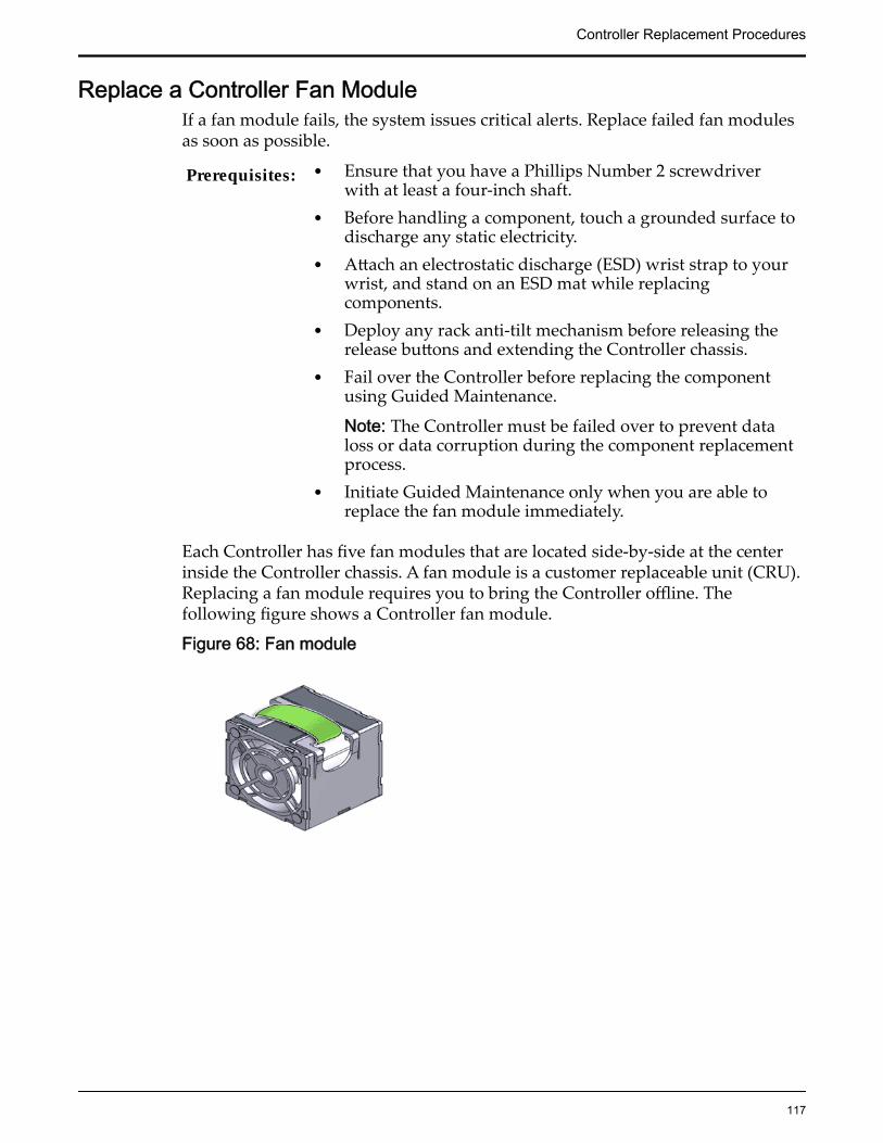
Replace a Controller Fan ModuleIf a fan module fails, the system issues critical alerts. Replace failed fan modulesas soon as possible.
Prerequisites: • Ensure that you have a Phillips Number 2 screwdriverwith at least a four-inch shaft.
• Before handling a component, touch a grounded surface todischarge any static electricity.
• Attach an electrostatic discharge (ESD) wrist strap to yourwrist, and stand on an ESD mat while replacingcomponents.
• Deploy any rack anti-tilt mechanism before releasing therelease buttons and extending the Controller chassis.
• Fail over the Controller before replacing the componentusing Guided Maintenance.
Note: The Controller must be failed over to prevent dataloss or data corruption during the component replacementprocess.
• Initiate Guided Maintenance only when you are able toreplace the fan module immediately.
Each Controller has five fan modules that are located side-by-side at the centerinside the Controller chassis. A fan module is a customer replaceable unit (CRU).Replacing a fan module requires you to bring the Controller offline. Thefollowing figure shows a Controller fan module.
Figure 68: Fan module
Controller Replacement Procedures
117

Figure 69: Fan module location
Legend 1 Fan module-0
2 Fan module-1
3 Fan module-2
4 Fan module-3
5 Fan module-4
Note: The fan modules can be accessed only after removing the top cover overthe Controller chassis.
Note: To replace a fan module, you do not need to remove the Controller fromthe rack but extend it along the Controller rails using the cable management arm(CMA).
Note: Ensure that all power is removed from the Controller before replacing thefan module. Disconnect the power cables before performing the fan modulereplacement procedure.
Note: For fan replacement, the Replaceable Unit list displays the names of eachfan. Each power supply contains one fan, and each fan module contains two fans.If a fan fails in a power supply, replace the power supply. If a fan fails in a fanmodule, replace the fan module. The following list identifies the names of thefans and the corresponding customer replaceable unit (CRU).
If the following fan fails Replace the following CRUFan 0 Power supply 0Fan 1 Power supply 1Fans 2, 3 Fan module 0Fans 4, 5 Fan module 1
Controller Replacement Procedures
118

If the following fan fails Replace the following CRUFans 6, 7 Fan module 2Fans 8, 9 Fan module 3Fans 10, 11 Fan module 4
Procedure Overview
1 Prepare the Component for Replacement
2 Remove the Controller Power Supply Cords
3 Slide Controller to Service Position
4 Open the Controller Top Cover
5 Remove a Fan Module
6 Insert a Fan Module
7 Close the Controller Top Cover
8 Complete the Component Replacement
9 Verify Controller Component Status
Related LinksController Components
Prepare the Component for Replacement1 From Oracle FS System Manager (GUI), navigate to System > Hardware >
Controllers and then select the Controller that contains the component thatis to be replaced.
2 Select Actions > View.
The View dialog displays the components in the Replaceable Unit list. TheStatus column lists the status of each component. A status of Normalrequires no action.
Note: Field replaceable units (FRUs) can only be replaced by fieldtechnicians with support role privileges.
3 Select a component from the list and click Replace Component.
Guided Maintenance displays an image of the chassis.
4 Click Next.
Guided Maintenance displays the Identify Hardware dialog.
5 From the Identify Hardware dialog, specify how you want to identify thechassis so that you can locate it in the data center.
You can select one of the following methods to identify the chassis:
Controller Replacement Procedures
119

Identify Flashes the LEDs on the chassis that contains the failedcomponent.
ReverseIdentify
Flashes the LEDs on all of the chassis in the system exceptfor the chassis that contains the failed component.
6 Click Next.
Based on the method you selected to identify the chassis, thecorresponding LEDs flash to help you locate the chassis in the data center.
7 Click Next.
For components that are not hot-serviceable, Guided Maintenance sends arequest to shut down the software running on the Controller andautomatically initiates failover. Guided Maintenance also displays anHTML link that you use to access the instructions for componentreplacement.
For hot-serviceable components, Guided Maintenance completes theprocess of preparing the system for component replacement and displaysthe Replace Hardware dialog. The Replace Hardware dialog instructs youto replace the component. You also receive a System Alert informing youthat the component is ready for removal. To review System Alerts,navigate to System > Alerts and Events > System Alerts.
Remove the Controller Power Supply Cords
Disconnect the power cords from both power supplies.
Figure 70: Remove power supply cords
Legend 1 Power supply cords
2 Power supply handle
Tip: Always notify affected users that the Controller will be shut down.
Controller Replacement Procedures
120

Slide Controller to Service Position
Squeeze the release buttons on either side of the Controller front panel atthe same time and slide the Controller chassis forward until the slide railslock into position. You might have to remove screws locking the frontpanel to the rack before the Controller slides forward.
Figure 71: Slide the Controller to service position
Legend 1 Rack
2 Controller chassis
3 Release buttons
Important: Before you slide the Controller chassis out, ensure that thecables do not interfere with the movement of the Controller chassis.Although the cable management arm (CMA) is hinged so that you canextend the Controller chassis, all cables and cords must be out of the waywhen you service the Controller components.
CAUTION: Deploy any rack anti-tilt mechanism before releasing therelease buttons and extending the Controller chassis.
Open the Controller Top Cover
Controller Replacement Procedures
121
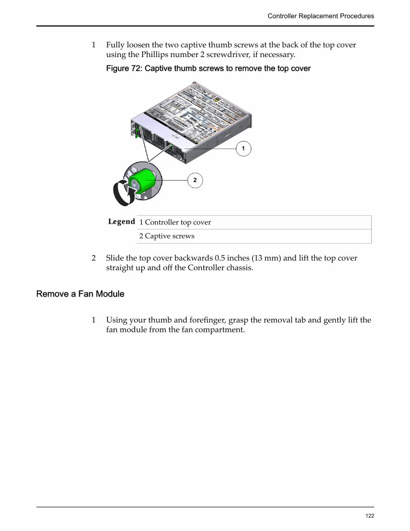
1 Fully loosen the two captive thumb screws at the back of the top coverusing the Phillips number 2 screwdriver, if necessary.
Figure 72: Captive thumb screws to remove the top cover
Legend 1 Controller top cover
2 Captive screws
2 Slide the top cover backwards 0.5 inches (13 mm) and lift the top coverstraight up and off the Controller chassis.
Remove a Fan Module
1 Using your thumb and forefinger, grasp the removal tab and gently lift thefan module from the fan compartment.
Controller Replacement Procedures
122

Figure 73: Remove fan module
Legend 1 Controller chassis
2 Fan compartment
3 Removal tab
4 Fan module
Note: Pulling the green tab from the middle releases the locking tab foreach individual fan.
Note: When removing a fan module, do not rock it back and forth. Rockingthe fan module can cause damage to the motherboard connectors.
2 Set the fan module aside.
Note: The fan compartment might come out when the last fan module isremoved.
Insert a Fan Module
Insert the replacement fan module into the Controller.
Controller Replacement Procedures
123

Figure 74: Insert fan module
Legend 1 Controller chassis
2 Fan compartment
3 Fan module
Note: Press down on the fan module and apply firm pressure to fully seatthe fan module into the fan compartment. The fan modules are notched toensure that they are installed in the correct orientation.
Note: Repeat for each additional fan module.
Close the Controller Top Cover
Place the top cover of the Controller and tighten the two thumb screws atthe back of the Controller that secure the top cover.
Controller Replacement Procedures
124
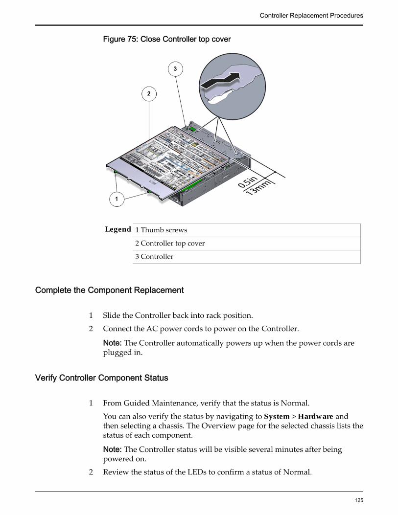
Figure 75: Close Controller top cover
Legend 1 Thumb screws
2 Controller top cover
3 Controller
Complete the Component Replacement
1 Slide the Controller back into rack position.
2 Connect the AC power cords to power on the Controller.
Note: The Controller automatically powers up when the power cords areplugged in.
Verify Controller Component Status
1 From Guided Maintenance, verify that the status is Normal.
You can also verify the status by navigating to System > Hardware andthen selecting a chassis. The Overview page for the selected chassis lists thestatus of each component.
Note: The Controller status will be visible several minutes after beingpowered on.
2 Review the status of the LEDs to confirm a status of Normal.
Controller Replacement Procedures
125

Replace a Controller Power SupplyPower supplies, which exist in pairs, provide DC power to all of the Controllercomponents. If one power supply fails, the other supply carries the full load. Thissituation creates a risk of Controller failure should the other power supply alsofail.
A failed Controller can cause data paths to drop.
Prerequisites: • Deploy any rack anti-tilt mechanism before releasingthe release buttons and extending the Controller.
• Before handling a component, touch a groundedsurface to discharge any static electricity.
• Attach an electrostatic discharge (ESD) wrist strap toyour wrist, and stand on an ESD mat while replacingcomponents.
• Make sure you have a similar replacement powersupply available before you start the replacementprocedure.
• Initiate Guided Maintenance only when you are ableto replace the power supplies immediately.
Each Controller has a pair of power supplies that are located at the back of theController. Power supplies are customer replaceable units (CRUs). Replacing apower supply does not require you to bring the Controller offline, provided thatthe other power supply is online and working. The following figure identifies thelocation of the Controller power supplies.
Figure 76: Power supply location
Legend 1 Power supply-0 (PS-0)
2 Power supply-1 (PS-1)
Note: To replace a power supply, you can access the faulted power supply fromthe back of the Controller module. To access the power supply located in the
Controller Replacement Procedures
126

bottom slot (PS-1), the CMA clip must be disconnected to enable the powersupply to clear the support arm.
Note: Replacing the power supply does not require you to slide the Controllerinto the extended rack position and can be performed while the Controller is inthe rack position.
Note: Ensure that the power strain relief strap on the power supply is positionedcorrectly such that there is proper clearance and the power supplies can be re-inserted into the power supply compartment without interference.
Note: Ensure that the power cable is routed correctly and there is no interferencewith the Controller chassis.
Important: Do not remove the failed power supply until you have a replacementpower supply to ensure proper airflow in the Controller.
Note: For fan replacement, the Replaceable Unit list displays the names of eachfan. Each power supply contains one fan, and each fan module contains two fans.If a fan fails in a power supply, replace the power supply. If a fan fails in a fanmodule, replace the fan module. The following list identifies the names of thefans and the corresponding customer replaceable unit (CRU).
If the following fan fails Replace the following CRUFan 0 Power supply 0Fan 1 Power supply 1Fans 2, 3 Fan module 0Fans 4, 5 Fan module 1Fans 6, 7 Fan module 2Fans 8, 9 Fan module 3Fans 10, 11 Fan module 4
Procedure Overview
1 Prepare the Component for Replacement
2 Remove the Power Cords
3 Remove a Power Supply
4 Insert a Power Supply
5 Insert the Power Cords
6 Verify Controller Component Status
Related LinksController Components
Controller Replacement Procedures
127
Prepare the Component for Replacement1 From Oracle FS System Manager (GUI), navigate to System > Hardware >
Controllers and then select the Controller that contains the component thatis to be replaced.
2 Select Actions > View.
The View dialog displays the components in the Replaceable Unit list. TheStatus column lists the status of each component. A status of Normalrequires no action.
Note: Field replaceable units (FRUs) can only be replaced by fieldtechnicians with support role privileges.
3 Select a component from the list and click Replace Component.
Guided Maintenance displays an image of the chassis.4 Click Next.
Guided Maintenance displays the Identify Hardware dialog.5 From the Identify Hardware dialog, specify how you want to identify the
chassis so that you can locate it in the data center.
You can select one of the following methods to identify the chassis:
Identify Flashes the LEDs on the chassis that contains the failedcomponent.
ReverseIdentify
Flashes the LEDs on all of the chassis in the system exceptfor the chassis that contains the failed component.
6 Click Next.
Based on the method you selected to identify the chassis, thecorresponding LEDs flash to help you locate the chassis in the data center.
7 Click Next.
For components that are not hot-serviceable, Guided Maintenance sends arequest to shut down the software running on the Controller andautomatically initiates failover. Guided Maintenance also displays anHTML link that you use to access the instructions for componentreplacement.
For hot-serviceable components, Guided Maintenance completes theprocess of preparing the system for component replacement and displaysthe Replace Hardware dialog. The Replace Hardware dialog instructs youto replace the component. You also receive a System Alert informing youthat the component is ready for removal. To review System Alerts,navigate to System > Alerts and Events > System Alerts.
Remove the Power Cords
Disconnect the power cord from the power supply.
Controller Replacement Procedures
128

Figure 77: Disconnect the power cord
Legend 1 Power supply cord
2 Power supply handle
Note: Ensure that the power cord has been disconnected from the faultedpower supply.
Tip: Always notify affected users that the Controller will be shut down.
Remove a Power Supply
1 Remove the power supply by grasping the power supply handle andpushing the power supply latch to the left.
Figure 78: Controller power supply latch
Legend 1 Power supply handle 3 Power supply
Controller Replacement Procedures
129

2 Power supply latch 4 Controller back
Figure 79: Remove power supply
Legend 1 Power supply
2 Power supply compartment
3 Controller
2 If both power supplies must be removed, label the power supplies with theslot numbers from which they are removed.
Note: Removing both power supplies will result in the immediateshutdown of the Controller. Do not pull both power supplies from anactive and running Controller.
Note: The power supplies must be re-installed into the same slots fromwhich they were removed.
3 Pull the power supply out of the chassis and place it on an antistatic mat.
Insert a Power Supply
1 Slide the replacement power supply into the power supply compartment atthe back of the Controller until it is fully seated.
Controller Replacement Procedures
130
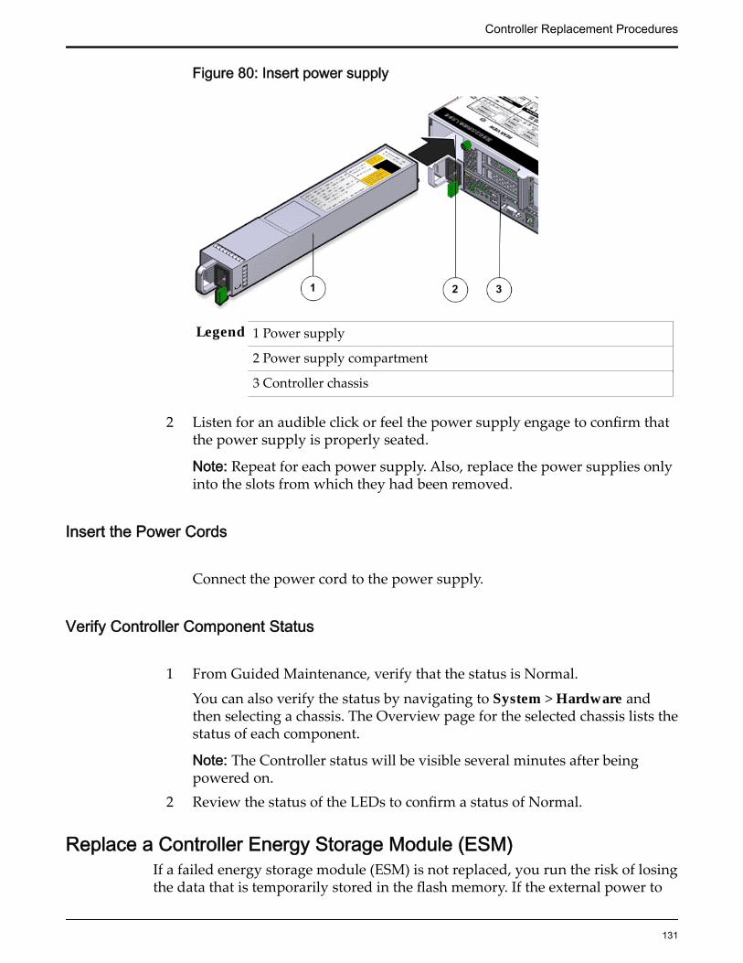
Figure 80: Insert power supply
Legend 1 Power supply
2 Power supply compartment
3 Controller chassis
2 Listen for an audible click or feel the power supply engage to confirm thatthe power supply is properly seated.
Note: Repeat for each power supply. Also, replace the power supplies onlyinto the slots from which they had been removed.
Insert the Power Cords
Connect the power cord to the power supply.
Verify Controller Component Status
1 From Guided Maintenance, verify that the status is Normal.
You can also verify the status by navigating to System > Hardware andthen selecting a chassis. The Overview page for the selected chassis lists thestatus of each component.
Note: The Controller status will be visible several minutes after beingpowered on.
2 Review the status of the LEDs to confirm a status of Normal.
Replace a Controller Energy Storage Module (ESM)If a failed energy storage module (ESM) is not replaced, you run the risk of losingthe data that is temporarily stored in the flash memory. If the external power to
Controller Replacement Procedures
131

the Controller is lost as well, the potential for data loss rises dramatically. In caseof an ESM failure, the Controller should go into write-through (conservative)mode so there is no data loss. Nevertheless, a failed ESM must be replaced assoon as possible to avoid the risk of data loss and to restore system performance.
Prerequisites: • Before handling a component, touch a grounded surface todischarge any static electricity.
• Attach an electrostatic discharge (ESD) wrist strap to yourwrist, and stand on an ESD mat while replacingcomponents.
• Ensure that a replacement ESM or a filler panel available toreplace the ESM that you will be removing.
Each Controller has one ESM for every NVDIMM. ESMs are located inside theController's ESM drive compartment. An Oracle Flash Storage System with abasic configuration contains two ESMs and two NVDIMMs. An Oracle FS Systemconfigured for performance contains four ESMs and four NVDIMMS. ESMs arecustomer replaceable units (CRUs). The following figure shows the location ofthe ESM modules.
Figure 81: ESM
Legend 1 ESM 0
2 ESM1
3 ESM 2
Controller Replacement Procedures
132

4 ESM 3
Important: Do not mix ESM and NVDIMM types. ESM type must match theNVDIMM type. For example, an ESM labeled A (ESM-A) must be paired with anNVDIMM labeled A (NVDIMM-A); The NVDIMM type is printed on a smalllabel near the end of the NVDIMM cable.
Note: To replace an ESM, you do not need to remove the Controller from the rackor even extend it along the Controller rails.
Note: Make a note of the ESM slot where the failed ESM was located so that thereplacement ESM can be placed in the same slot to avoid the risk of mis-configuration. Alternatively, replace the ESMs only one at a time, so that there isonly one empty ESM slot at any point in time.
Procedure Overview
1 Prepare the Component for Replacement
2 Remove an Air Filter
3 Remove a Controller Energy Storage Module (ESM)
4 Insert an Energy Storage Module
5 Insert an Air Filter
6 Verify Controller Component Status
Related LinksController Components
Prepare the Component for Replacement1 From Oracle FS System Manager (GUI), navigate to System > Hardware >
Controllers and then select the Controller that contains the component thatis to be replaced.
2 Select Actions > View.
The View dialog displays the components in the Replaceable Unit list. TheStatus column lists the status of each component. A status of Normalrequires no action.
Note: Field replaceable units (FRUs) can only be replaced by fieldtechnicians with support role privileges.
3 Select a component from the list and click Replace Component.
Guided Maintenance displays an image of the chassis.4 Click Next.
Guided Maintenance displays the Identify Hardware dialog.5 From the Identify Hardware dialog, specify how you want to identify the
chassis so that you can locate it in the data center.
Controller Replacement Procedures
133

You can select one of the following methods to identify the chassis:
Identify Flashes the LEDs on the chassis that contains the failedcomponent.
ReverseIdentify
Flashes the LEDs on all of the chassis in the system exceptfor the chassis that contains the failed component.
6 Click Next.
Based on the method you selected to identify the chassis, thecorresponding LEDs flash to help you locate the chassis in the data center.
7 Click Next.
For components that are not hot-serviceable, Guided Maintenance sends arequest to shut down the software running on the Controller andautomatically initiates failover. Guided Maintenance also displays anHTML link that you use to access the instructions for componentreplacement.
For hot-serviceable components, Guided Maintenance completes theprocess of preparing the system for component replacement and displaysthe Replace Hardware dialog. The Replace Hardware dialog instructs youto replace the component. You also receive a System Alert informing youthat the component is ready for removal. To review System Alerts,navigate to System > Alerts and Events > System Alerts.
Remove an Air Filter
1 At the front of the Controller chassis, locate the air filter release tabs.
2 Press the release tabs inwards at the same time to unlock the tabs anddisengage the air filter.
Figure 82: Air filter release tabs
Controller Replacement Procedures
134

Legend 1 Release tabs
2 Air filter
3 Carefully rotate the top of the air filter outwards and as the release tabsdisengage, lift out the filter.
Figure 83: Remove air filter
4 Set the air filter aside.
Remove a Controller Energy Storage Module (ESM)
1 Remove the Controller ESM from the drive compartment by pushing thelatch release button to open the latch.
Figure 84: Open ESM latch
Controller Replacement Procedures
135

Legend 1 ESM
2 Latch release button
3 Controller front
Important: Do not bend the latch too far to the right. Bending the latch candamage the latch.
Important: When you remove an ESM, be sure to replace it immediatelywith another ESM or a filler panel. Otherwise, the Controller mightoverheat because of improper airflow.
2 Grasp the latch and pull the ESM out of the Controller drive compartment.
Figure 85: Remove ESM
Legend 1 ESM
2 Controller drive compartment
3 Controller front
3 Set the failed component aside.
Insert an Energy Storage Module
1 Insert the ESM into the correct slot.
Note: The Controller might have filler panels covering the empty slots inthe ESM drive compartment.
2 Slide the replacement ESM into the drive compartment until the ESM isfully seated into the slot.
Controller Replacement Procedures
136
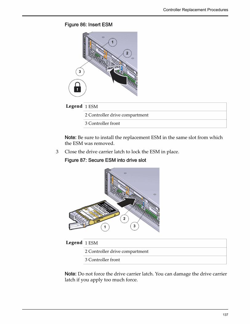
Figure 86: Insert ESM
Legend 1 ESM
2 Controller drive compartment
3 Controller front
Note: Be sure to install the replacement ESM in the same slot from whichthe ESM was removed.
3 Close the drive carrier latch to lock the ESM in place.
Figure 87: Secure ESM into drive slot
Legend 1 ESM
2 Controller drive compartment
3 Controller front
Note: Do not force the drive carrier latch. You can damage the drive carrierlatch if you apply too much force.
Controller Replacement Procedures
137

Power On the ControllerPower on the Controller using the power button and the ILOM webinterface.
Note: As soon as the power cords are connected to the Controller, standbypower is applied. In standby power mode, the Power/OK LED on theController front panel blinks every five seconds or so. However, to applymain power to the Controller, you must use the power button and the webinterface. When main power is applied to the Controller, the green Power/OK LED on the front panel of the Controller blinks steadily. When theController BIOS has completed booting, the OK LED remains lit.
Insert an Air Filter
1 Tilt the top of the air filter slightly towards you and insert the bottom twohooks into the mounting tabs.
Figure 88: Insert air filter
Important: Ensure that nothing interferes with the edges of the air filter andthat the air filter seats properly.
2 Press the top corners of the air filter to engage the top two air filter hookswith the top rail tabs.
3 Press both air filter release tabs until they lock in place.
Verify Controller Component Status
1 From Guided Maintenance, verify that the status is Normal.
Controller Replacement Procedures
138
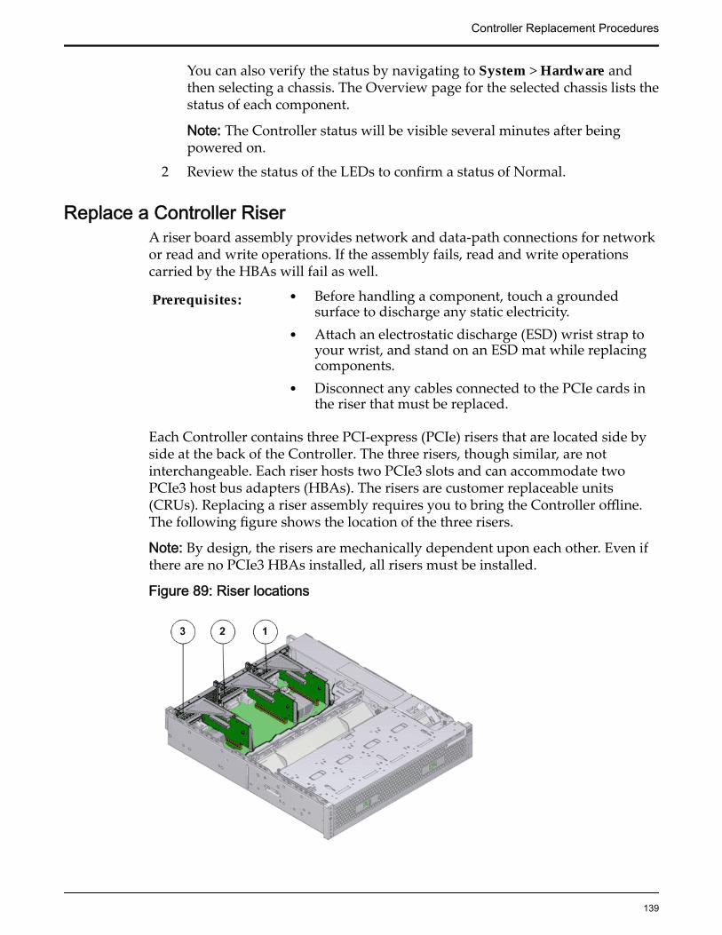
You can also verify the status by navigating to System > Hardware andthen selecting a chassis. The Overview page for the selected chassis lists thestatus of each component.
Note: The Controller status will be visible several minutes after beingpowered on.
2 Review the status of the LEDs to confirm a status of Normal.
Replace a Controller RiserA riser board assembly provides network and data-path connections for networkor read and write operations. If the assembly fails, read and write operationscarried by the HBAs will fail as well.
Prerequisites: • Before handling a component, touch a groundedsurface to discharge any static electricity.
• Attach an electrostatic discharge (ESD) wrist strap toyour wrist, and stand on an ESD mat while replacingcomponents.
• Disconnect any cables connected to the PCIe cards inthe riser that must be replaced.
Each Controller contains three PCI-express (PCIe) risers that are located side byside at the back of the Controller. The three risers, though similar, are notinterchangeable. Each riser hosts two PCIe3 slots and can accommodate twoPCIe3 host bus adapters (HBAs). The risers are customer replaceable units(CRUs). Replacing a riser assembly requires you to bring the Controller offline.The following figure shows the location of the three risers.
Note: By design, the risers are mechanically dependent upon each other. Even ifthere are no PCIe3 HBAs installed, all risers must be installed.
Figure 89: Riser locations
Controller Replacement Procedures
139

Legend 1 Riser 1
2 Riser 2
3 Riser 3 with latch
Note: The risers can be accessed only after removing the top cover over theController chassis.
Note: To replace a riser, you do not need to remove the Controller from the rackbut extend it along the Controller rails using the cable management arm (CMA).
Note: Ensure that all power is removed from the Controller before replacing theriser. Disconnect the power cords before performing the riser replacementprocedure.
Procedure Overview
1 Prepare the Component for Replacement
2 Remove the Controller Power Supply Cords
3 Slide Controller to Service Position
4 Disconnect Controller Cabling
5 Open the Controller Top Cover
6 Remove a Riser
7 Insert a Riser
8 Close the Controller Top Cover
9 Reconnect Controller Cabling
10 Complete the Component Replacement
11 Verify Controller Component Status
Related LinksController Components
Prepare the Component for Replacement
1 From Oracle FS System Manager (GUI), navigate to Support > SystemTrouble.
2 Select the Controller that contains the component that is to be replaced.
3 Select Actions > Replace Component.Guided Maintenance displays the list of replaceable components for theController.
Note: Field replaceable units (FRUs) can only be replaced by fieldtechnicians with support role privileges.
4 Select a component from the list.
Controller Replacement Procedures
140
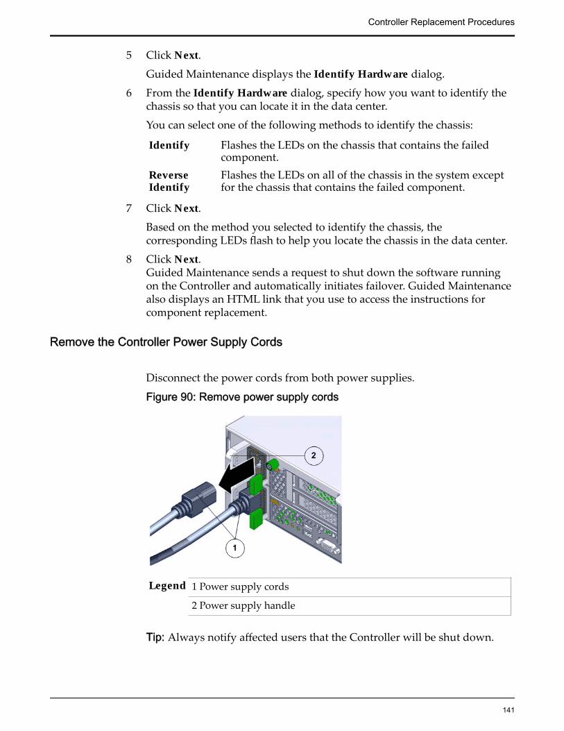
5 Click Next.
Guided Maintenance displays the Identify Hardware dialog.
6 From the Identify Hardware dialog, specify how you want to identify thechassis so that you can locate it in the data center.
You can select one of the following methods to identify the chassis:
Identify Flashes the LEDs on the chassis that contains the failedcomponent.
ReverseIdentify
Flashes the LEDs on all of the chassis in the system exceptfor the chassis that contains the failed component.
7 Click Next.
Based on the method you selected to identify the chassis, thecorresponding LEDs flash to help you locate the chassis in the data center.
8 Click Next.Guided Maintenance sends a request to shut down the software runningon the Controller and automatically initiates failover. Guided Maintenancealso displays an HTML link that you use to access the instructions forcomponent replacement.
Remove the Controller Power Supply Cords
Disconnect the power cords from both power supplies.
Figure 90: Remove power supply cords
Legend 1 Power supply cords
2 Power supply handle
Tip: Always notify affected users that the Controller will be shut down.
Controller Replacement Procedures
141

Slide Controller to Service Position
Squeeze the release buttons on either side of the Controller front panel atthe same time and slide the Controller chassis forward until the slide railslock into position. You might have to remove screws locking the frontpanel to the rack before the Controller slides forward.
Figure 91: Slide the Controller to service position
Legend 1 Rack
2 Controller chassis
3 Release buttons
Important: Before you slide the Controller chassis out, ensure that thecables do not interfere with the movement of the Controller chassis.Although the cable management arm (CMA) is hinged so that you canextend the Controller chassis, all cables and cords must be out of the waywhen you service the Controller components.
CAUTION: Deploy any rack anti-tilt mechanism before releasing therelease buttons and extending the Controller chassis.
Controller Replacement Procedures
142

Disconnect Controller CablingDisconnect all data cables from the Controller.
Note: All cables must be dis-connected from the Controller and labelledsuch that they can be reconnected accurately to the Controller after thereplacement procedure is complete. Reconnecting cables to the incorrectposition might impact the performance of the Controller or result in acomplete loss of functionality.
Note: Service the Controller components from the front of the Controllerwhile the Controller is in service position.
Note: Do not lean on or place any weight on the Controller while theController is in the service position.
Open the Controller Top Cover
1 Fully loosen the two captive thumb screws at the back of the top coverusing the Phillips number 2 screwdriver, if necessary.
Figure 92: Captive thumb screws to remove the top cover
Legend 1 Controller top cover
2 Captive screws
2 Slide the top cover backwards 0.5 inches (13 mm) and lift the top coverstraight up and off the Controller chassis.
Remove a Riser
1 Disconnect any external cables that remain connected to the HBAs in therisers.
Controller Replacement Procedures
143

Note: Also disconnect any internal cables attached to the HBAs, if that willease removing the HBA.
Tip: Make a note of the positions of all existing cable connections beforeremoving any cables. Replacing HBAs or their cables into the incorrectposition in the riser may result in a loss of performance or functionality.
2 Note the position of the HBAs installed on the riser.
Tip: Make a note of the slot numbers of all existing HBAs before removingany HBAs.
3 Using a Phillips Number 2 screwdriver, loosen the two Phillips Number 2captive screws on either side of the riser that hold the riser to theController motherboard.
Note: The riser on the opposite end of the power supply has a latch thatmust be disengaged to remove the riser from the Controller chassis
Figure 93: Captive screws to secure the risers
Legend 1 Riser 3 with latch 3 Riser 1
2 Riser 2 4 Captive screws that secure riser
To remove riser 3, unlock the latch to release the riser from the Controllermotherboard.
Controller Replacement Procedures
144

Figure 94: Unlock Riser 3 latch
Legend 1 Riser 3 latch 3 HBA
2 Riser 3
4 Carefully pull the riser straight up and place it aside.
Figure 95: Remove riser
Legend 1 Riser
2 Controller motherboard
Controller Replacement Procedures
145
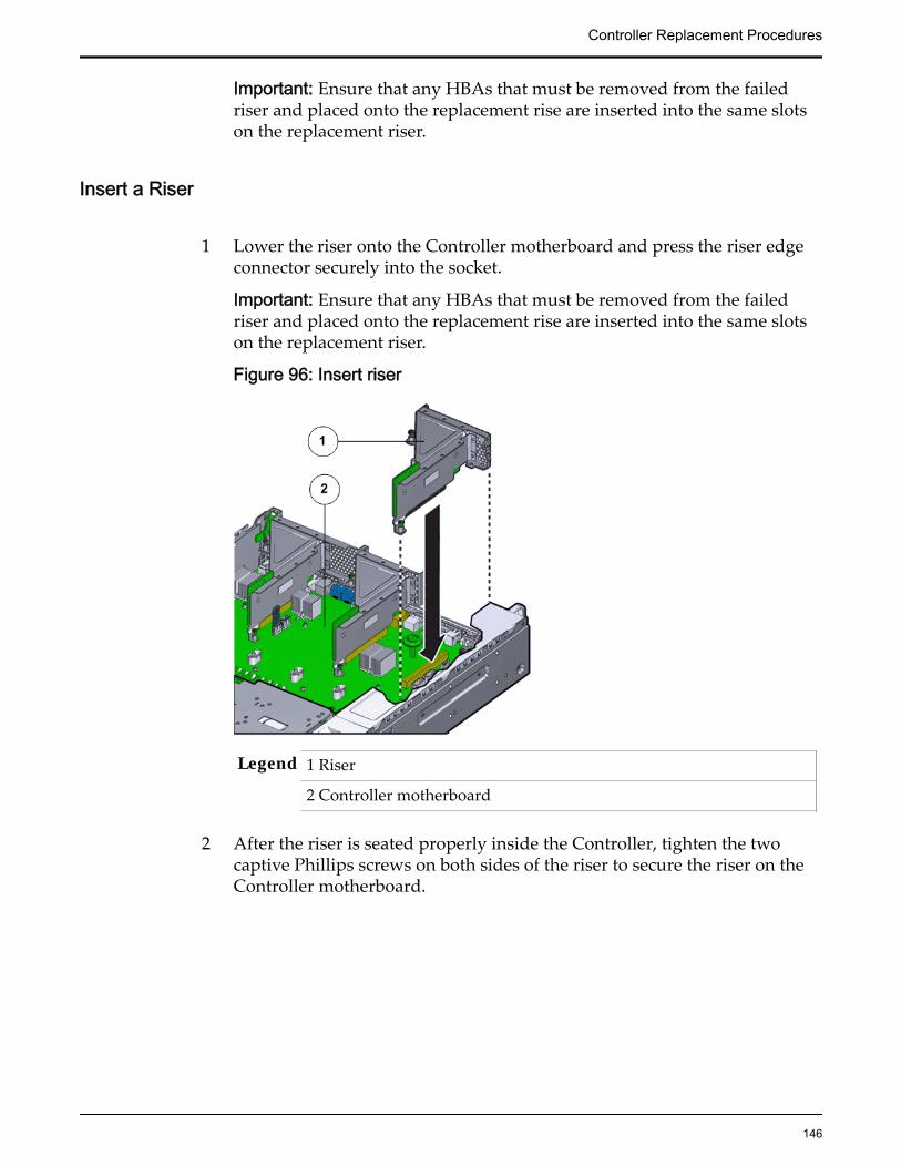
Important: Ensure that any HBAs that must be removed from the failedriser and placed onto the replacement rise are inserted into the same slotson the replacement riser.
Insert a Riser
1 Lower the riser onto the Controller motherboard and press the riser edgeconnector securely into the socket.
Important: Ensure that any HBAs that must be removed from the failedriser and placed onto the replacement rise are inserted into the same slotson the replacement riser.
Figure 96: Insert riser
Legend 1 Riser
2 Controller motherboard
2 After the riser is seated properly inside the Controller, tighten the twocaptive Phillips screws on both sides of the riser to secure the riser on theController motherboard.
Controller Replacement Procedures
146
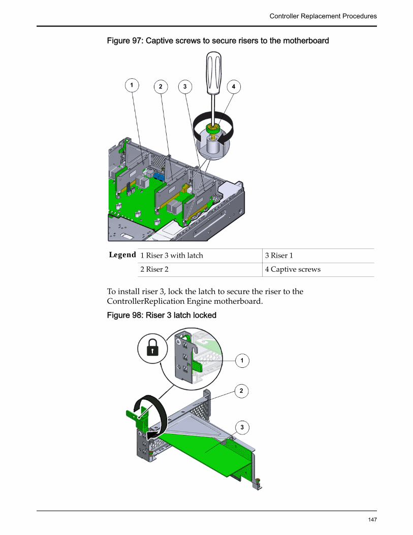
Figure 97: Captive screws to secure risers to the motherboard
Legend 1 Riser 3 with latch 3 Riser 1
2 Riser 2 4 Captive screws
To install riser 3, lock the latch to secure the riser to theControllerReplication Engine motherboard.
Figure 98: Riser 3 latch locked
Controller Replacement Procedures
147
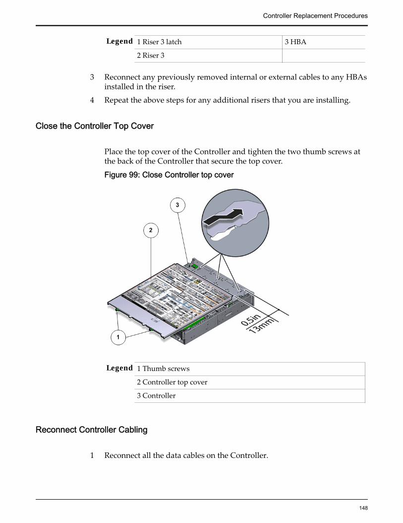
Legend 1 Riser 3 latch 3 HBA
2 Riser 3
3 Reconnect any previously removed internal or external cables to any HBAsinstalled in the riser.
4 Repeat the above steps for any additional risers that you are installing.
Close the Controller Top Cover
Place the top cover of the Controller and tighten the two thumb screws atthe back of the Controller that secure the top cover.
Figure 99: Close Controller top cover
Legend 1 Thumb screws
2 Controller top cover
3 Controller
Reconnect Controller Cabling
1 Reconnect all the data cables on the Controller.
Controller Replacement Procedures
148

Note: Oracle Customer Support recommends labeling all cables connectedto the Controller so that the cables can be reconnected accurately to theController after the replacement procedure is complete.
2 Reconnect the CMA to the Controller by attaching the release tab on theleft and right side of the CMA.
Complete the Component Replacement
1 Slide the Controller back into rack position.
2 Connect the AC power cords to power on the Controller.
Note: The Controller automatically powers up when the power cords areplugged in.
Verify Controller Component Status
1 From Guided Maintenance, verify that the status is Normal.
You can also verify the status by navigating to System > Hardware andthen selecting a chassis. The Overview page for the selected chassis lists thestatus of each component.
Note: The Controller status will be visible several minutes after beingpowered on.
2 Review the status of the LEDs to confirm a status of Normal.
Replace a Controller HBAAn HBA is a circuit board installed inside the Controller riser board assembly.
A failed HBA might cause a Controller failure that could result in the remainingControllers to shoulder the load. Therefore, if failed, an HBA must be replacedimmediately. Additional HBAs can also be added to existing configurations.
Prerequisites: • Ensure that you have a Phillips Number 2screwdriver with at least a four-inch shaft.
• Before handling a component, touch a groundedsurface to discharge any static electricity.
• Attach an electrostatic discharge (ESD) wrist strap toyour wrist, and stand on an ESD mat while replacingcomponents.
• Keep filler panels available in case you only removethe HBA and do not plan to replace the HBAimmediately.
Controller Replacement Procedures
149
Note: Filler panels ensure proper airflow inside theController.
• Use only the filler panels provided with theController to maintain proper airflow and EMIconformance for empty slots inside the Controller.
• Fail over the Controller before replacing thecomponent using Guided Maintenance.
Note: The Controller must be failed over to preventdata loss or data corruption during the componentreplacement process.
• Label all cables connected to the Controller so thatthey can be reconnected accurately to the Controllerafter the replacement procedure is complete.
Note: Replacing an HBA might require changes to the port’s world wide name(WWN).
Each Oracle Flash Storage System supports two types of HBA connectivity SAN(FC or iSCSI HBA 16Gb, optical only) and NAS (10 GbE HBA). The placement ofthe HBA inside the riser slot is based on the Oracle FS System configurationoption selected. All HBAs supported in the Oracle FS System are customerreplaceable units (CRUs). Replacement of an HBA requires you to bring theController offline. HBAs connecting to host servers must be placed into slots 1, 4,and 5 on the risers. HBAs connecting to Drive Enclosures must be placed intoslots 2, 3, and 6 on the risers. You must install all HBAs according to the slotnumbers listed in the following table.
HBA System type Slot number
16 Gb/s Fibre Channel (FC) or 10GbE iSCSI universal HBA,QLogic
SAN 1, 4, 5
10 Gb/s Ethernet dual port or fibre SFP+ NAS 1, 4, 5
6 Gb/s SAS PCIe-3, 4x4 port ALL 3,6,2
Note: Replacement of the HBA will result in a change to the world wide portname (WWPN) of the HBA
Note: If both Ethernet and FC HBA are used, insert the Ethernet HBA in the firstslot of the riser.
Procedure Overview
1 Prepare the Component for Replacement
2 Remove the Controller Power Supply Cords
3 Slide Controller to Service Position
4 Disconnect Controller Cabling
5 Open the Controller Top Cover
Controller Replacement Procedures
150

6 Remove a Riser
7 Remove an HBA
8 Insert an HBA
9 Insert a Riser
10 Close the Controller Top Cover
11 Reconnect Controller Cabling
12 Complete the Component Replacement
13 Verify Controller Component Status
Related LinksController Components
Prepare the Component for Replacement1 From Oracle FS System Manager (GUI), navigate to System > Hardware >
Controllers and then select the Controller that contains the component thatis to be replaced.
2 Select Actions > View.
The View dialog displays the components in the Replaceable Unit list. TheStatus column lists the status of each component. A status of Normalrequires no action.
Note: Field replaceable units (FRUs) can only be replaced by fieldtechnicians with support role privileges.
3 Select a component from the list and click Replace Component.
Guided Maintenance displays an image of the chassis.4 Click Next.
Guided Maintenance displays the Identify Hardware dialog.5 From the Identify Hardware dialog, specify how you want to identify the
chassis so that you can locate it in the data center.
You can select one of the following methods to identify the chassis:
Identify Flashes the LEDs on the chassis that contains the failedcomponent.
ReverseIdentify
Flashes the LEDs on all of the chassis in the system exceptfor the chassis that contains the failed component.
6 Click Next.
Based on the method you selected to identify the chassis, thecorresponding LEDs flash to help you locate the chassis in the data center.
7 Click Next.
For components that are not hot-serviceable, Guided Maintenance sends arequest to shut down the software running on the Controller and
Controller Replacement Procedures
151

automatically initiates failover. Guided Maintenance also displays anHTML link that you use to access the instructions for componentreplacement.
For hot-serviceable components, Guided Maintenance completes theprocess of preparing the system for component replacement and displaysthe Replace Hardware dialog. The Replace Hardware dialog instructs youto replace the component. You also receive a System Alert informing youthat the component is ready for removal. To review System Alerts,navigate to System > Alerts and Events > System Alerts.
Remove the Controller Power Supply Cords
Disconnect the power cords from both power supplies.
Figure 100: Remove power supply cords
Legend 1 Power supply cords
2 Power supply handle
Tip: Always notify affected users that the Controller will be shut down.
Slide Controller to Service Position
Squeeze the release buttons on either side of the Controller front panel atthe same time and slide the Controller chassis forward until the slide railslock into position. You might have to remove screws locking the frontpanel to the rack before the Controller slides forward.
Controller Replacement Procedures
152

Figure 101: Slide the Controller to service position
Legend 1 Rack
2 Controller chassis
3 Release buttons
Important: Before you slide the Controller chassis out, ensure that thecables do not interfere with the movement of the Controller chassis.Although the cable management arm (CMA) is hinged so that you canextend the Controller chassis, all cables and cords must be out of the waywhen you service the Controller components.
CAUTION: Deploy any rack anti-tilt mechanism before releasing therelease buttons and extending the Controller chassis.
Disconnect Controller Cabling
Disconnect all data cables from the Controller.
Note: All cables must be dis-connected from the Controller and labelledsuch that they can be reconnected accurately to the Controller after thereplacement procedure is complete. Reconnecting cables to the incorrect
Controller Replacement Procedures
153
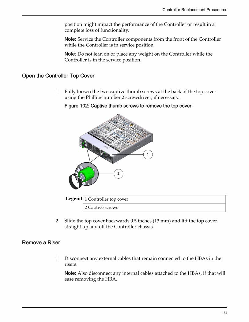
position might impact the performance of the Controller or result in acomplete loss of functionality.
Note: Service the Controller components from the front of the Controllerwhile the Controller is in service position.
Note: Do not lean on or place any weight on the Controller while theController is in the service position.
Open the Controller Top Cover
1 Fully loosen the two captive thumb screws at the back of the top coverusing the Phillips number 2 screwdriver, if necessary.
Figure 102: Captive thumb screws to remove the top cover
Legend 1 Controller top cover
2 Captive screws
2 Slide the top cover backwards 0.5 inches (13 mm) and lift the top coverstraight up and off the Controller chassis.
Remove a Riser
1 Disconnect any external cables that remain connected to the HBAs in therisers.
Note: Also disconnect any internal cables attached to the HBAs, if that willease removing the HBA.
Controller Replacement Procedures
154
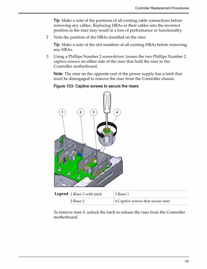
Tip: Make a note of the positions of all existing cable connections beforeremoving any cables. Replacing HBAs or their cables into the incorrectposition in the riser may result in a loss of performance or functionality.
2 Note the position of the HBAs installed on the riser.
Tip: Make a note of the slot numbers of all existing HBAs before removingany HBAs.
3 Using a Phillips Number 2 screwdriver, loosen the two Phillips Number 2captive screws on either side of the riser that hold the riser to theController motherboard.
Note: The riser on the opposite end of the power supply has a latch thatmust be disengaged to remove the riser from the Controller chassis
Figure 103: Captive screws to secure the risers
Legend 1 Riser 3 with latch 3 Riser 1
2 Riser 2 4 Captive screws that secure riser
To remove riser 3, unlock the latch to release the riser from the Controllermotherboard.
Controller Replacement Procedures
155

Figure 104: Unlock Riser 3 latch
Legend 1 Riser 3 latch 3 HBA
2 Riser 3
4 Carefully pull the riser straight up and place it aside.
Figure 105: Remove riser
Legend 1 Riser
2 Controller motherboard
Controller Replacement Procedures
156

Important: Ensure that any HBAs that must be removed from the failedriser and placed onto the replacement rise are inserted into the same slotson the replacement riser.
Remove an HBA
1 Disconnect any cables that are connected to the HBAs inside the riser.If you have not done so already, note the ports from which the cables aredisconnected in the HBA, so that the cables can be reconnected to theiroriginal ports when the HBA is replaced.
2 Swing the riser retainer latch (for riser 3) to its fully open (180 degrees)position.
Figure 106: Unlock riser retainer latch to release HBA
Legend 1 Riser retainer latch
2 HBA
3 Riser
3 Lift the HBA off of the alignment pin of the riser slot.
Controller Replacement Procedures
157
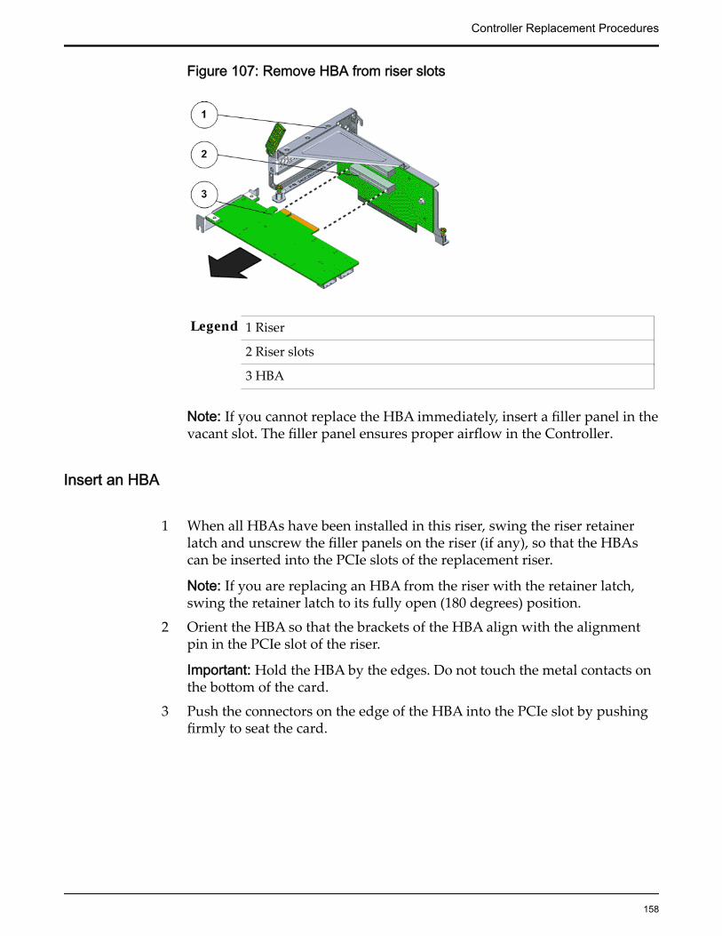
Figure 107: Remove HBA from riser slots
Legend 1 Riser
2 Riser slots
3 HBA
Note: If you cannot replace the HBA immediately, insert a filler panel in thevacant slot. The filler panel ensures proper airflow in the Controller.
Insert an HBA
1 When all HBAs have been installed in this riser, swing the riser retainerlatch and unscrew the filler panels on the riser (if any), so that the HBAscan be inserted into the PCIe slots of the replacement riser.
Note: If you are replacing an HBA from the riser with the retainer latch,swing the retainer latch to its fully open (180 degrees) position.
2 Orient the HBA so that the brackets of the HBA align with the alignmentpin in the PCIe slot of the riser.
Important: Hold the HBA by the edges. Do not touch the metal contacts onthe bottom of the card.
3 Push the connectors on the edge of the HBA into the PCIe slot by pushingfirmly to seat the card.
Controller Replacement Procedures
158

Figure 108: Insert HBA into riser slot
Legend 1 Riser
2 Riser slots
3 HBA
4 Apply firm pressure on each end of the HBA alternately until it clicks intoplace in the riser socket.
CAUTION: Support the HBA and the riser as necessary to preventexcessive flexure. Otherwise, the HBA or the riser card might be damaged.
5 When all HBAs have been installed in this riser, swing the retainer latch toits fully closed position. If there is resistance, check the alignment of theHBA and try again.
Figure 109: HBA retainer latch
Legend 1 Riser retainer latch
2 HBA
3 Riser
Controller Replacement Procedures
159
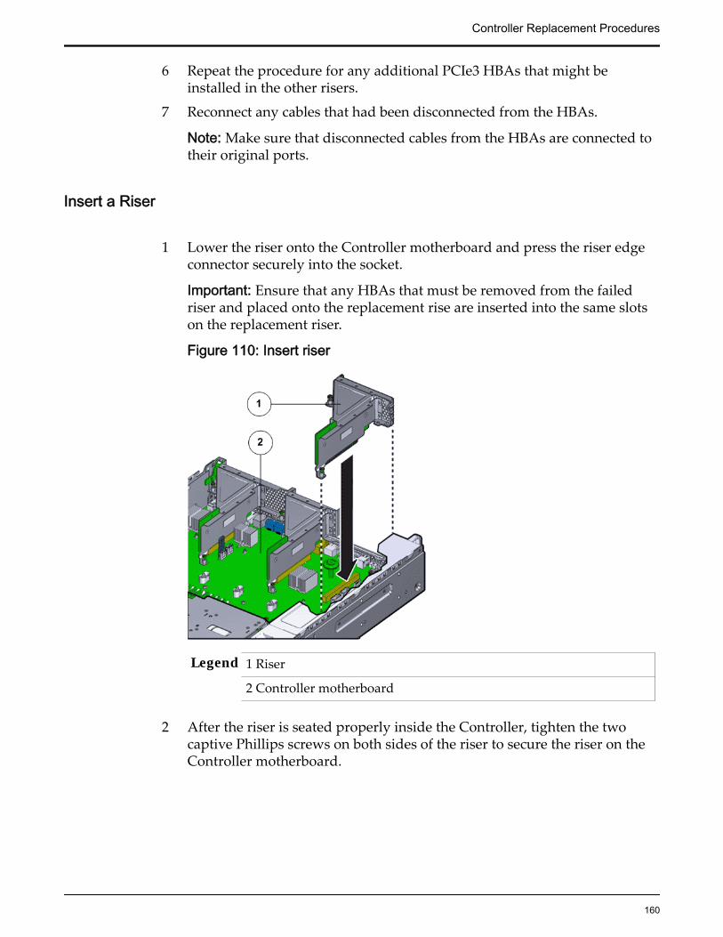
6 Repeat the procedure for any additional PCIe3 HBAs that might beinstalled in the other risers.
7 Reconnect any cables that had been disconnected from the HBAs.
Note: Make sure that disconnected cables from the HBAs are connected totheir original ports.
Insert a Riser
1 Lower the riser onto the Controller motherboard and press the riser edgeconnector securely into the socket.
Important: Ensure that any HBAs that must be removed from the failedriser and placed onto the replacement rise are inserted into the same slotson the replacement riser.
Figure 110: Insert riser
Legend 1 Riser
2 Controller motherboard
2 After the riser is seated properly inside the Controller, tighten the twocaptive Phillips screws on both sides of the riser to secure the riser on theController motherboard.
Controller Replacement Procedures
160

Figure 111: Captive screws to secure risers to the motherboard
Legend 1 Riser 3 with latch 3 Riser 1
2 Riser 2 4 Captive screws
To install riser 3, lock the latch to secure the riser to theControllerReplication Engine motherboard.
Figure 112: Riser 3 latch locked
Controller Replacement Procedures
161

Legend 1 Riser 3 latch 3 HBA
2 Riser 3
3 Reconnect any previously removed internal or external cables to any HBAsinstalled in the riser.
4 Repeat the above steps for any additional risers that you are installing.
Close the Controller Top Cover
Place the top cover of the Controller and tighten the two thumb screws atthe back of the Controller that secure the top cover.
Figure 113: Close Controller top cover
Legend 1 Thumb screws
2 Controller top cover
3 Controller
Reconnect Controller Cabling1 Reconnect all the data cables on the Controller.
Note: Oracle Customer Support recommends labeling all cables connectedto the Controller so that the cables can be reconnected accurately to theController after the replacement procedure is complete.
Controller Replacement Procedures
162

2 Reconnect the CMA to the Controller by attaching the release tab on theleft and right side of the CMA.
Complete the Component Replacement
1 Slide the Controller back into rack position.
2 Connect the AC power cords to power on the Controller.
Note: The Controller automatically powers up when the power cords areplugged in.
Verify Controller Component Status
1 From Guided Maintenance, verify that the status is Normal.
You can also verify the status by navigating to System > Hardware andthen selecting a chassis. The Overview page for the selected chassis lists thestatus of each component.
Note: The Controller status will be visible several minutes after beingpowered on.
2 Review the status of the LEDs to confirm a status of Normal.
Replace a Controller DIMMDual in-line memory modules (DIMMs) provide random access memory (RAM)for the central processing units (CPUs) configured in the Controller. DIMMs areconnected to the DIMM slots located on both sides of the central processing unit(CPUs) and heat sinks on the Controller motherboard. A failed DIMM mightcause the Controller to shut down and must be replaced as soon as possible.
Prerequisites: • Ensure that you have a Phillips Number 2screwdriver with at least a four-inch shaft.
• Before handling a component, touch a groundedsurface to discharge any static electricity.
• Attach an electrostatic discharge (ESD) wrist strap toyour wrist, and stand on an ESD mat while replacingcomponents.
• Fail over the Controller before replacing thecomponent using Guided Maintenance.
Controller Replacement Procedures
163
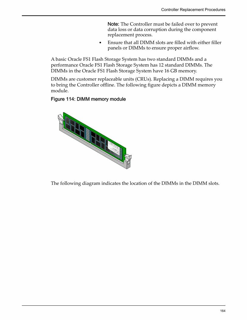
Note: The Controller must be failed over to preventdata loss or data corruption during the componentreplacement process.
• Ensure that all DIMM slots are filled with either fillerpanels or DIMMs to ensure proper airflow.
A basic Oracle FS1 Flash Storage System has two standard DIMMs and aperformance Oracle FS1 Flash Storage System has 12 standard DIMMs. TheDIMMs in the Oracle FS1 Flash Storage System have 16 GB memory.
DIMMs are customer replaceable units (CRUs). Replacing a DIMM requires youto bring the Controller offline. The following figure depicts a DIMM memorymodule.
Figure 114: DIMM memory module
The following diagram indicates the location of the DIMMs in the DIMM slots.
Controller Replacement Procedures
164
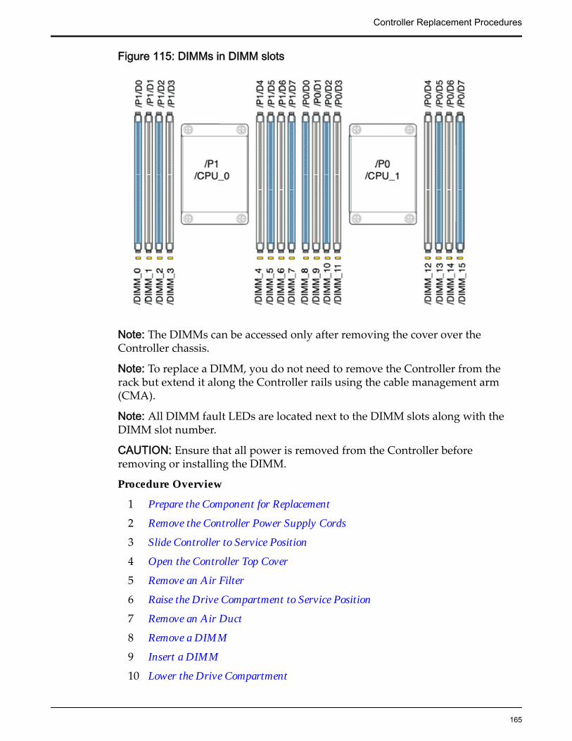
Figure 115: DIMMs in DIMM slots
Note: The DIMMs can be accessed only after removing the cover over theController chassis.
Note: To replace a DIMM, you do not need to remove the Controller from therack but extend it along the Controller rails using the cable management arm(CMA).
Note: All DIMM fault LEDs are located next to the DIMM slots along with theDIMM slot number.
CAUTION: Ensure that all power is removed from the Controller beforeremoving or installing the DIMM.
Procedure Overview
1 Prepare the Component for Replacement
2 Remove the Controller Power Supply Cords
3 Slide Controller to Service Position
4 Open the Controller Top Cover
5 Remove an Air Filter
6 Raise the Drive Compartment to Service Position
7 Remove an Air Duct
8 Remove a DIMM
9 Insert a DIMM
10 Lower the Drive Compartment
Controller Replacement Procedures
165

11 Insert an Air Duct
12 Insert an Air Filter
13 Close the Controller Top Cover
14 Complete the Component Replacement
15 Verify Controller Component Status
Related LinksController Components
Prepare the Component for Replacement1 From Oracle FS System Manager (GUI), navigate to System > Hardware >
Controllers and then select the Controller that contains the component thatis to be replaced.
2 Select Actions > View.
The View dialog displays the components in the Replaceable Unit list. TheStatus column lists the status of each component. A status of Normalrequires no action.
Note: Field replaceable units (FRUs) can only be replaced by fieldtechnicians with support role privileges.
3 Select a component from the list and click Replace Component.
Guided Maintenance displays an image of the chassis.
4 Click Next.
Guided Maintenance displays the Identify Hardware dialog.
5 From the Identify Hardware dialog, specify how you want to identify thechassis so that you can locate it in the data center.
You can select one of the following methods to identify the chassis:
Identify Flashes the LEDs on the chassis that contains the failedcomponent.
ReverseIdentify
Flashes the LEDs on all of the chassis in the system exceptfor the chassis that contains the failed component.
6 Click Next.
Based on the method you selected to identify the chassis, thecorresponding LEDs flash to help you locate the chassis in the data center.
7 Click Next.
For components that are not hot-serviceable, Guided Maintenance sends arequest to shut down the software running on the Controller andautomatically initiates failover. Guided Maintenance also displays anHTML link that you use to access the instructions for componentreplacement.
Controller Replacement Procedures
166
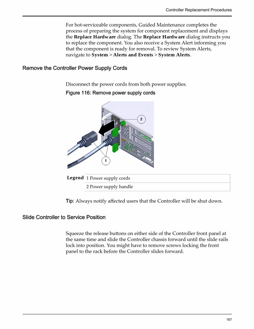
For hot-serviceable components, Guided Maintenance completes theprocess of preparing the system for component replacement and displaysthe Replace Hardware dialog. The Replace Hardware dialog instructs youto replace the component. You also receive a System Alert informing youthat the component is ready for removal. To review System Alerts,navigate to System > Alerts and Events > System Alerts.
Remove the Controller Power Supply Cords
Disconnect the power cords from both power supplies.
Figure 116: Remove power supply cords
Legend 1 Power supply cords
2 Power supply handle
Tip: Always notify affected users that the Controller will be shut down.
Slide Controller to Service Position
Squeeze the release buttons on either side of the Controller front panel atthe same time and slide the Controller chassis forward until the slide railslock into position. You might have to remove screws locking the frontpanel to the rack before the Controller slides forward.
Controller Replacement Procedures
167

Figure 117: Slide the Controller to service position
Legend 1 Rack
2 Controller chassis
3 Release buttons
Important: Before you slide the Controller chassis out, ensure that thecables do not interfere with the movement of the Controller chassis.Although the cable management arm (CMA) is hinged so that you canextend the Controller chassis, all cables and cords must be out of the waywhen you service the Controller components.
CAUTION: Deploy any rack anti-tilt mechanism before releasing therelease buttons and extending the Controller chassis.
Open the Controller Top Cover
1 Fully loosen the two captive thumb screws at the back of the top coverusing the Phillips number 2 screwdriver, if necessary.
Controller Replacement Procedures
168

Figure 118: Captive thumb screws to remove the top cover
Legend 1 Controller top cover
2 Captive screws
2 Slide the top cover backwards 0.5 inches (13 mm) and lift the top coverstraight up and off the Controller chassis.
Remove an Air Filter1 At the front of the Controller chassis, locate the air filter release tabs.2 Press the release tabs inwards at the same time to unlock the tabs and
disengage the air filter.
Figure 119: Air filter release tabs
Legend 1 Release tabs
Controller Replacement Procedures
169
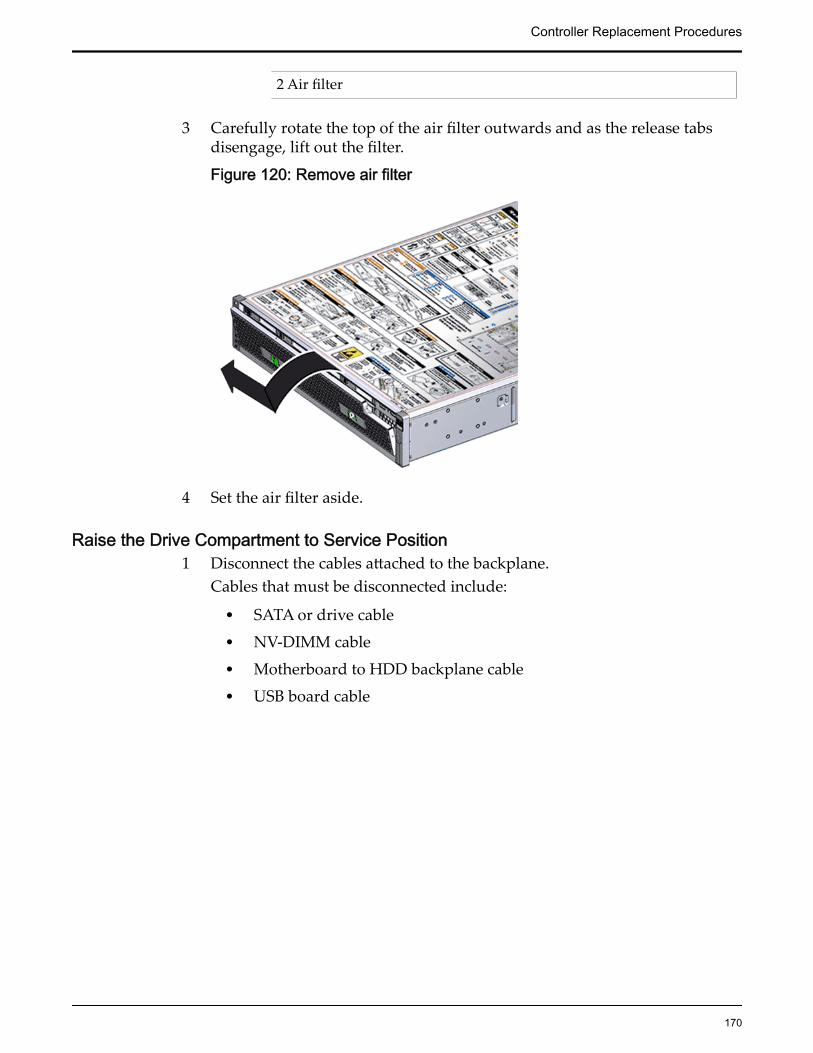
2 Air filter
3 Carefully rotate the top of the air filter outwards and as the release tabsdisengage, lift out the filter.
Figure 120: Remove air filter
4 Set the air filter aside.
Raise the Drive Compartment to Service Position1 Disconnect the cables attached to the backplane.
Cables that must be disconnected include:
• SATA or drive cable
• NV-DIMM cable
• Motherboard to HDD backplane cable
• USB board cable
Controller Replacement Procedures
170
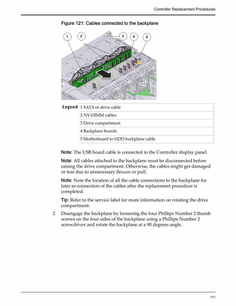
Figure 121: Cables connected to the backplane
Legend 1 SATA or drive cable
2 NV-DIMM cables
3 Drive compartment
4 Backplane boards
5 Motherboard to HDD backplane cable
Note: The USB board cable is connected to the Controller display panel.
Note: All cables attached to the backplane must be disconnected beforeraising the drive compartment. Otherwise, the cables might get damagedor tear due to unnecessary flexure or pull.
Note: Note the location of all the cable connections to the backplane forlater re-connection of the cables after the replacement procedure iscompleted.
Tip: Refer to the service label for more information on rotating the drivecompartment.
2 Disengage the backplane by loosening the four Phillips Number 2 thumbscrews on the four sides of the backplane using a Phillips Number 2screwdriver and rotate the backplane at a 90 degrees angle.
Controller Replacement Procedures
171

Figure 122: Disengaging the backplane
Legend 1 Thumb screws that secure the backplane
2 Backplane
Note: Use the screwdriver very carefully to avoid damaging the electricalcircuitry inside the Controller.
3 Raise the backplane and drive compartment to the vertical position.
Figure 123: Drive compartment raised
Controller Replacement Procedures
172
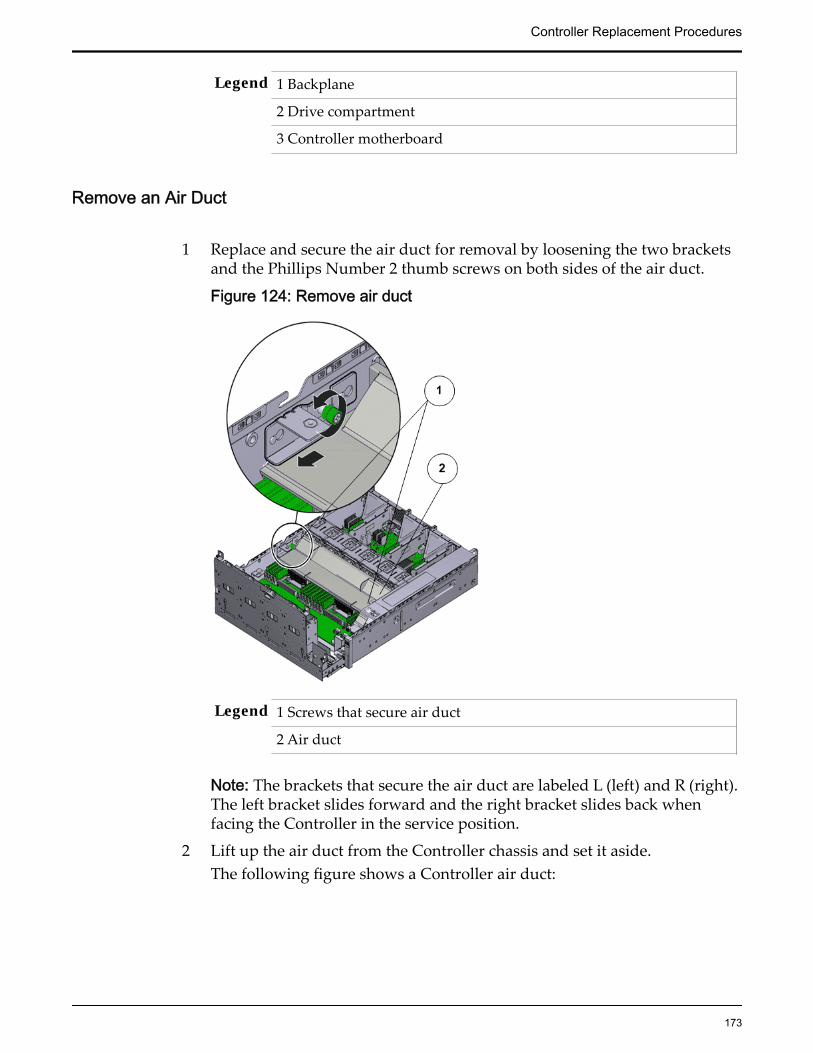
Legend 1 Backplane
2 Drive compartment
3 Controller motherboard
Remove an Air Duct
1 Replace and secure the air duct for removal by loosening the two bracketsand the Phillips Number 2 thumb screws on both sides of the air duct.
Figure 124: Remove air duct
Legend 1 Screws that secure air duct
2 Air duct
Note: The brackets that secure the air duct are labeled L (left) and R (right).The left bracket slides forward and the right bracket slides back whenfacing the Controller in the service position.
2 Lift up the air duct from the Controller chassis and set it aside.The following figure shows a Controller air duct:
Controller Replacement Procedures
173
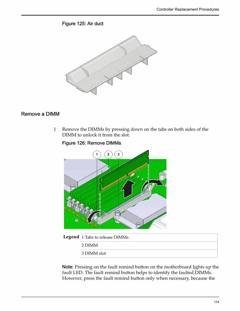
Figure 125: Air duct
Remove a DIMM
1 Remove the DIMMs by pressing down on the tabs on both sides of theDIMM to unlock it from the slot.
Figure 126: Remove DIMMs
Legend 1 Tabs to release DIMMs
2 DIMM
3 DIMM slot
Note: Pressing on the fault remind button on the motherboard lights up thefault LED. The fault remind button helps to identify the faulted DIMMs.However, press the fault remind button only when necessary, because the
Controller Replacement Procedures
174
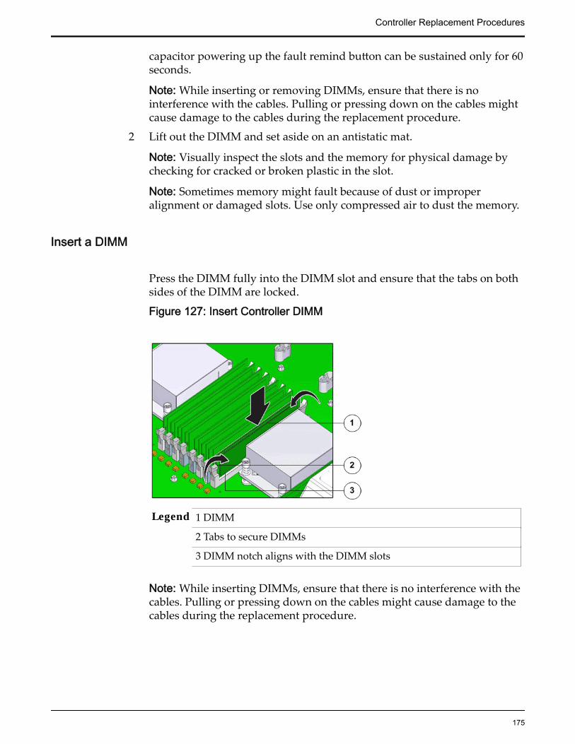
capacitor powering up the fault remind button can be sustained only for 60seconds.
Note: While inserting or removing DIMMs, ensure that there is nointerference with the cables. Pulling or pressing down on the cables mightcause damage to the cables during the replacement procedure.
2 Lift out the DIMM and set aside on an antistatic mat.
Note: Visually inspect the slots and the memory for physical damage bychecking for cracked or broken plastic in the slot.
Note: Sometimes memory might fault because of dust or improperalignment or damaged slots. Use only compressed air to dust the memory.
Insert a DIMM
Press the DIMM fully into the DIMM slot and ensure that the tabs on bothsides of the DIMM are locked.
Figure 127: Insert Controller DIMM
Legend 1 DIMM
2 Tabs to secure DIMMs
3 DIMM notch aligns with the DIMM slots
Note: While inserting DIMMs, ensure that there is no interference with thecables. Pulling or pressing down on the cables might cause damage to thecables during the replacement procedure.
Controller Replacement Procedures
175

Figure 128: DIMM alignment over DIMM slots
Important: Ensure that the notch in the DIMM lines up with the key in theslot.
Note: Replace only one DIMM at a time to make sure that they are insertedinto the correct slots. Attempting to insert multiple DIMMs into the slotsmight damage the DIMMs due to excessive flexure.
Note: Never leave a DIMM slot unpopulated. Insert fillers into empty slotsto ensure proper air flow inside the Controller.
Lower the Drive Compartment1 Rotate the drive compartment and backplane back into position inside the
Controller and ensure that the alignment pins engage.
Note: To confirm that the backplane is locked into position, listen for anaudible click or feel the backplane engage with the Controller.
2 Secure the backplane inside the Controller by inserting the four PhillipsNumber 2 thumb screws on the four sides of the backplane and tighteningthem using a Phillips Number 2 screwdriver.
3 Reconnect all the cables that had been previously disconnected from thebackplane.Cables that must be reconnected include:
• SATA or drive cable
• NV-DIMM cable
• Motherboard to HDD backplane cable
Controller Replacement Procedures
176
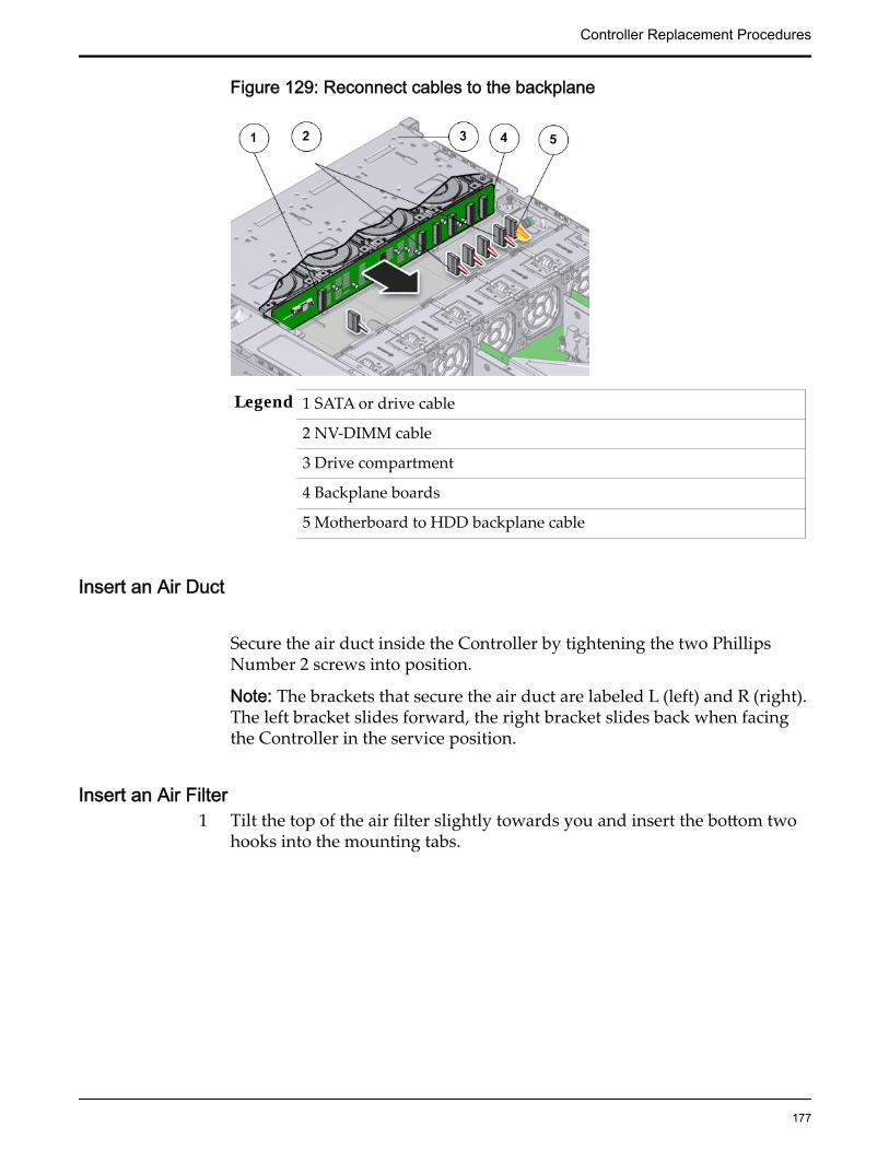
Figure 129: Reconnect cables to the backplane
Legend 1 SATA or drive cable
2 NV-DIMM cable
3 Drive compartment
4 Backplane boards
5 Motherboard to HDD backplane cable
Insert an Air Duct
Secure the air duct inside the Controller by tightening the two PhillipsNumber 2 screws into position.
Note: The brackets that secure the air duct are labeled L (left) and R (right).The left bracket slides forward, the right bracket slides back when facingthe Controller in the service position.
Insert an Air Filter1 Tilt the top of the air filter slightly towards you and insert the bottom two
hooks into the mounting tabs.
Controller Replacement Procedures
177

Figure 130: Insert air filter
Important: Ensure that nothing interferes with the edges of the air filter andthat the air filter seats properly.
2 Press the top corners of the air filter to engage the top two air filter hookswith the top rail tabs.
3 Press both air filter release tabs until they lock in place.
Close the Controller Top Cover
Place the top cover of the Controller and tighten the two thumb screws atthe back of the Controller that secure the top cover.
Controller Replacement Procedures
178

Figure 131: Close Controller top cover
Legend 1 Thumb screws
2 Controller top cover
3 Controller
Complete the Component Replacement
1 Slide the Controller back into rack position.
2 Connect the AC power cords to power on the Controller.
Note: The Controller automatically powers up when the power cords areplugged in.
Verify Controller Component Status
1 From Guided Maintenance, verify that the status is Normal.
You can also verify the status by navigating to System > Hardware andthen selecting a chassis. The Overview page for the selected chassis lists thestatus of each component.
Note: The Controller status will be visible several minutes after beingpowered on.
2 Review the status of the LEDs to confirm a status of Normal.
Controller Replacement Procedures
179

Replace a Controller NV-DIMMNon-volatile dual inline memory module (NV-DIMM) backs up data without abattery. In case of a power failure or system crash, the data in the NV-DIMM issecurely preserved and available almost immediately upon power being restoredto the Controller. A failed NV-DIMM can shut down the Controller and must berestored as soon as possible.
Prerequisites: • Ensure that you have a Phillips Number 2screwdriver with at least a four-inch shaft.
• Before handling a component, touch a groundedsurface to discharge any static electricity.
• Attach an electrostatic discharge (ESD) wrist strap toyour wrist, and stand on an ESD mat while replacingcomponents.
• Ensure that all DIMM and NV-DIMM slots are filledwith either filler panels or DIMMs or NV-DIMMs toensure proper airflow.
• Ensure that the ESM type matches the NV-DIMMtype. For example: ESM-A with NV-DIMM-A.
• Rotate the ESM drive cage and remove the air duct toaccess the NV-DIMMs for replacement.
• Fail over the Controller before replacing thecomponent using Guided Maintenance.
Note: The Controller must be failed over to preventdata loss or data corruption during the componentreplacement process.
An Oracle Flash Storage System with a basic configuration contains two NV-DIMMs. An Oracle FS System configured for performance contains four NV-DIMMS. Each NV-DIMM is connected to an energy storage module (ESM)through a cable. If the power to the Controller is lost, each NV-DIMM receivespower from the ESM to preserve the data in the NV-DIMM until power isrestored and the Controller software recovers the data. This prevents the data inthe cache from being destabilized. An NV-DIMM is a field replaceable unit(FRU). Replacing an NV-DIMM requires you to bring the Controller offline. Thefollowing figure shows a close-up view of the NV-DIMM.
Controller Replacement Procedures
180

Figure 132: NV-DIMM
Note: The NV-DIMMs can be accessed only after removing the cover over theController chassis.
Note: Do not mix ESM and NVDIMM types. ESM type must match theNVDIMM type. For example, an ESM labelled A (ESM-A) must be paired withan NVDIMM labelled A (NVDIMM-A); The NVDIMM type is printed on a smalllabel near the end of the NVDIMM cable.
Note: To replace an NV-DIMM, you do not need to remove the Controller fromthe rack but extend it along the Controller rails using the cable management arm(CMA).
Note: All NV-DIMM fault LEDs are located next to the NV-DIMM slots alongwith the NV-DIMM slot number.
CAUTION: Ensure that all power is removed from the Controller beforeremoving or installing the NV-DIMM. Disconnect the power cables beforeperforming the NV-DIMM replacement procedure.
Procedure Overview
1 Prepare the Component for Replacement
2 Remove the Controller Power Supply Cords
3 Slide Controller to Service Position
4 Open the Controller Top Cover
5 Raise the Drive Compartment to Service Position
6 Remove an Air Duct
7 Remove an NV-DIMM
8 Insert an NVDIMM
9 Insert an Air Duct
10 Lower the Drive Compartment
Controller Replacement Procedures
181

11 Close the Controller Top Cover
12 Complete the Component Replacement
13 Verify Controller Component Status
Related LinksController Components
Prepare the Component for Replacement1 From Oracle FS System Manager (GUI), navigate to System > Hardware >
Controllers and then select the Controller that contains the component thatis to be replaced.
2 Select Actions > View.
The View dialog displays the components in the Replaceable Unit list. TheStatus column lists the status of each component. A status of Normalrequires no action.
Note: Field replaceable units (FRUs) can only be replaced by fieldtechnicians with support role privileges.
3 Select a component from the list and click Replace Component.
Guided Maintenance displays an image of the chassis.4 Click Next.
Guided Maintenance displays the Identify Hardware dialog.5 From the Identify Hardware dialog, specify how you want to identify the
chassis so that you can locate it in the data center.
You can select one of the following methods to identify the chassis:
Identify Flashes the LEDs on the chassis that contains the failedcomponent.
ReverseIdentify
Flashes the LEDs on all of the chassis in the system exceptfor the chassis that contains the failed component.
6 Click Next.
Based on the method you selected to identify the chassis, thecorresponding LEDs flash to help you locate the chassis in the data center.
7 Click Next.
For components that are not hot-serviceable, Guided Maintenance sends arequest to shut down the software running on the Controller andautomatically initiates failover. Guided Maintenance also displays anHTML link that you use to access the instructions for componentreplacement.
For hot-serviceable components, Guided Maintenance completes theprocess of preparing the system for component replacement and displaysthe Replace Hardware dialog. The Replace Hardware dialog instructs you
Controller Replacement Procedures
182
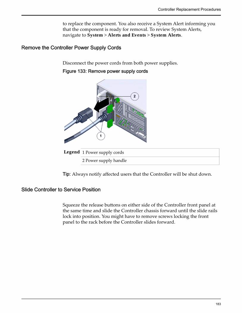
to replace the component. You also receive a System Alert informing youthat the component is ready for removal. To review System Alerts,navigate to System > Alerts and Events > System Alerts.
Remove the Controller Power Supply Cords
Disconnect the power cords from both power supplies.
Figure 133: Remove power supply cords
Legend 1 Power supply cords
2 Power supply handle
Tip: Always notify affected users that the Controller will be shut down.
Slide Controller to Service Position
Squeeze the release buttons on either side of the Controller front panel atthe same time and slide the Controller chassis forward until the slide railslock into position. You might have to remove screws locking the frontpanel to the rack before the Controller slides forward.
Controller Replacement Procedures
183

Figure 134: Slide the Controller to service position
Legend 1 Rack
2 Controller chassis
3 Release buttons
Important: Before you slide the Controller chassis out, ensure that thecables do not interfere with the movement of the Controller chassis.Although the cable management arm (CMA) is hinged so that you canextend the Controller chassis, all cables and cords must be out of the waywhen you service the Controller components.
CAUTION: Deploy any rack anti-tilt mechanism before releasing therelease buttons and extending the Controller chassis.
Open the Controller Top Cover
1 Fully loosen the two captive thumb screws at the back of the top coverusing the Phillips number 2 screwdriver, if necessary.
Controller Replacement Procedures
184
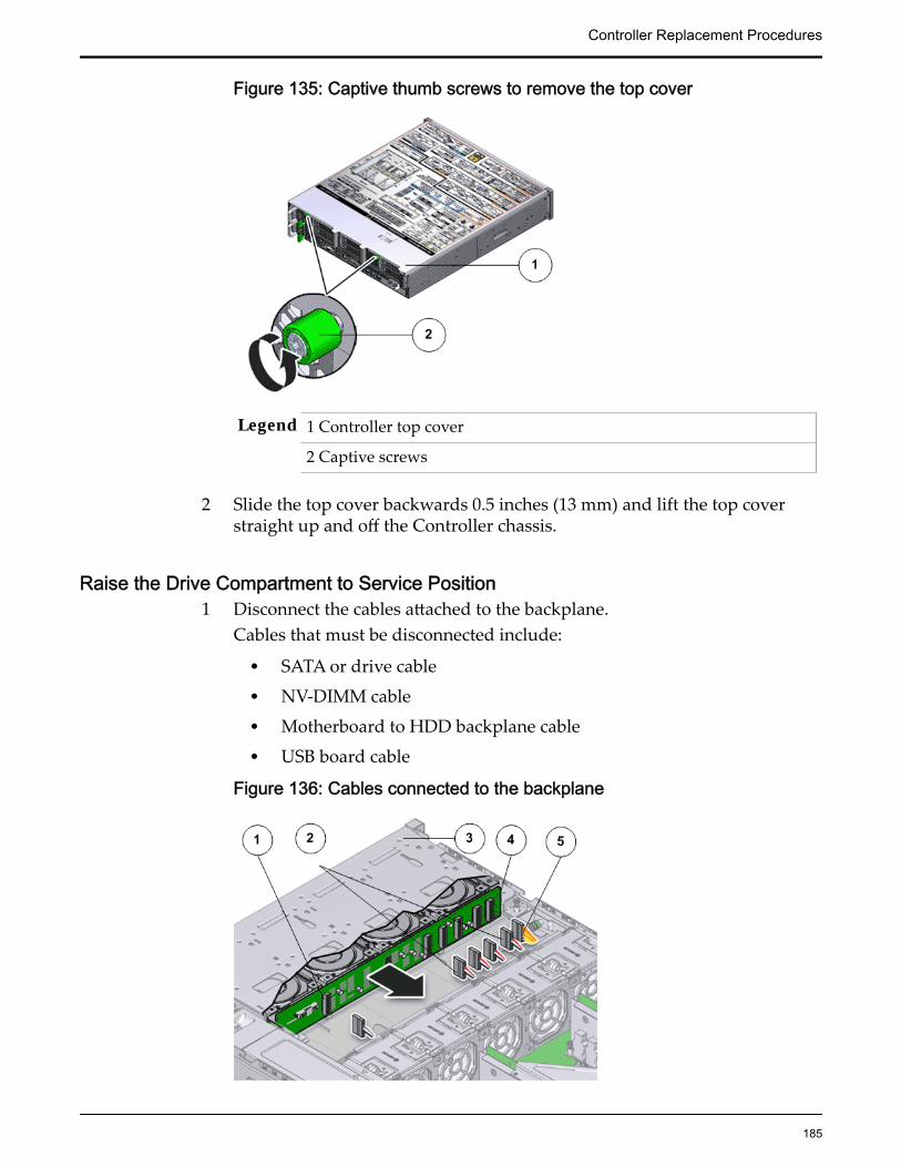
Figure 135: Captive thumb screws to remove the top cover
Legend 1 Controller top cover
2 Captive screws
2 Slide the top cover backwards 0.5 inches (13 mm) and lift the top coverstraight up and off the Controller chassis.
Raise the Drive Compartment to Service Position1 Disconnect the cables attached to the backplane.
Cables that must be disconnected include:
• SATA or drive cable
• NV-DIMM cable
• Motherboard to HDD backplane cable
• USB board cable
Figure 136: Cables connected to the backplane
Controller Replacement Procedures
185
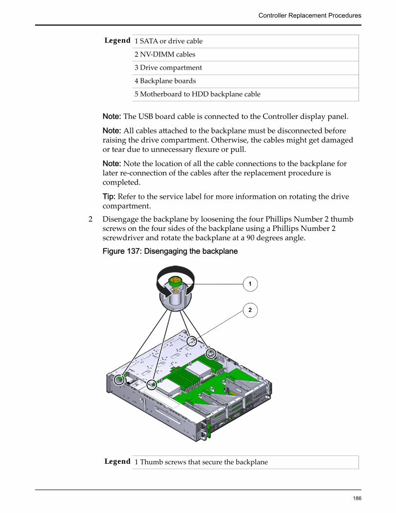
Legend 1 SATA or drive cable
2 NV-DIMM cables
3 Drive compartment
4 Backplane boards
5 Motherboard to HDD backplane cable
Note: The USB board cable is connected to the Controller display panel.
Note: All cables attached to the backplane must be disconnected beforeraising the drive compartment. Otherwise, the cables might get damagedor tear due to unnecessary flexure or pull.
Note: Note the location of all the cable connections to the backplane forlater re-connection of the cables after the replacement procedure iscompleted.
Tip: Refer to the service label for more information on rotating the drivecompartment.
2 Disengage the backplane by loosening the four Phillips Number 2 thumbscrews on the four sides of the backplane using a Phillips Number 2screwdriver and rotate the backplane at a 90 degrees angle.
Figure 137: Disengaging the backplane
Legend 1 Thumb screws that secure the backplane
Controller Replacement Procedures
186

2 Backplane
Note: Use the screwdriver very carefully to avoid damaging the electricalcircuitry inside the Controller.
3 Raise the backplane and drive compartment to the vertical position.
Figure 138: Drive compartment raised
Legend 1 Backplane
2 Drive compartment
3 Controller motherboard
Remove an Air Duct
1 Replace and secure the air duct for removal by loosening the two bracketsand the Phillips Number 2 thumb screws on both sides of the air duct.
Controller Replacement Procedures
187

Figure 139: Remove air duct
Legend 1 Screws that secure air duct
2 Air duct
Note: The brackets that secure the air duct are labeled L (left) and R (right).The left bracket slides forward and the right bracket slides back whenfacing the Controller in the service position.
2 Lift up the air duct from the Controller chassis and set it aside.The following figure shows a Controller air duct:
Figure 140: Air duct
Controller Replacement Procedures
188

Remove an NV-DIMM
1 Remove the NV-DIMMs by pressing down on the tabs on both sides of theNV-DIMM to unlock it from the slot.
Figure 141: Remove an NV-DIMM
Legend 1 Tabs to release NV-DIMM
2 NV-DIMM
3 NV-DIMM slot
Note: While inserting or removing NV-DIMMs, ensure that there is nointerference with the cables. Pulling or pressing down on the cables mightcause damage to the cables during the replacement procedure.
Note: Pressing the fault remind button on the motherboard lights up thefault LEDs of the NV-DIMMs even if the power cords are dis-connected.The fault remind button helps to identify the faulted LEDs.
2 Lift out the NV-DIMM from the slot and set aside on an antistatic mat.
Note: Visually inspect the DIMM slots, NV-DIMM slots, the DIMM, andthe NV-DIMM for physical damage by checking for cracked or brokenplastic in the slot.
Note: Sometimes DIMMs and NV-DIMMs might fault because of dust orimproper alignment or damaged slots. Use only compressed air to dustDIMMs or NV-DIMMs.
Insert an NVDIMM
Controller Replacement Procedures
189
Press the NV-DIMM fully into the NV-DIMM slot and ensure that the tabson both sides of the NV-DIMM are locked.
Important: Ensure that the notch in the NV-DIMM lines up with the key inthe slot.
Note: Replace only one NV-DIMM at a time to make sure that they areinserted into the correct slots. Attempting to insert multiple NV-DIMMsinto the slots might damage the NV-DIMMs due to excessive flexure.
Note: Never leave a DIMM or an NV-DIMM slot unpopulated. Insert fillersinto empty DIMM or NV-DIMM slots to ensure proper air flow inside theController.
Note: NV-DIMM slot numbering is different from ESM slot numbering.Refer to the NV-DIMM-to-ESM cabling map on the service label of theESM drive cage for more information.
Insert an Air Duct
Secure the air duct inside the Controller by tightening the two PhillipsNumber 2 screws into position.
Note: The brackets that secure the air duct are labeled L (left) and R (right).The left bracket slides forward, the right bracket slides back when facingthe Controller in the service position.
Lower the Drive Compartment1 Rotate the drive compartment and backplane back into position inside the
Controller and ensure that the alignment pins engage.
Note: To confirm that the backplane is locked into position, listen for anaudible click or feel the backplane engage with the Controller.
2 Secure the backplane inside the Controller by inserting the four PhillipsNumber 2 thumb screws on the four sides of the backplane and tighteningthem using a Phillips Number 2 screwdriver.
3 Reconnect all the cables that had been previously disconnected from thebackplane.Cables that must be reconnected include:
• SATA or drive cable
• NV-DIMM cable
• Motherboard to HDD backplane cable
Controller Replacement Procedures
190

Figure 142: Reconnect cables to the backplane
Legend 1 SATA or drive cable
2 NV-DIMM cable
3 Drive compartment
4 Backplane boards
5 Motherboard to HDD backplane cable
Close the Controller Top Cover
Place the top cover of the Controller and tighten the two thumb screws atthe back of the Controller that secure the top cover.
Controller Replacement Procedures
191

Figure 143: Close Controller top cover
Legend 1 Thumb screws
2 Controller top cover
3 Controller
Complete the Component Replacement
1 Slide the Controller back into rack position.
2 Connect the AC power cords to power on the Controller.
Note: The Controller automatically powers up when the power cords areplugged in.
Verify Controller Component Status
1 From Guided Maintenance, verify that the status is Normal.
You can also verify the status by navigating to System > Hardware andthen selecting a chassis. The Overview page for the selected chassis lists thestatus of each component.
Note: The Controller status will be visible several minutes after beingpowered on.
2 Review the status of the LEDs to confirm a status of Normal.
Controller Replacement Procedures
192
Replace a Controller ESM BackplaneThe energy storage module (ESM) backplane provides a physical interconnect forthe ESMs. The ESM backplane, if damaged, prevents the ESM modules fromseating properly. Improper seating prevents the modules from providing backuppower to flash memory, which can lead to data loss.
Prerequisites: • Ensure that you have a Phillips Number 2screwdriver with at least a four-inch shaft.
• Before handling a component, touch a groundedsurface to discharge any static electricity.
• Attach an electrostatic discharge (ESD) wrist strap toyour wrist, and stand on an ESD mat while replacingcomponents.
• Remove the ESMs from the ESM drive compartmentand make a note of the drive slots so that they can bere-inserted after the replacement procedure.
• Note the slot positions of the ESMs and the boot drivebefore performing the replacement procedure for theESM backplane.
• Fail over the Controller before replacing thecomponent using Guided Maintenance.
Note: The Controller must be failed over to preventdata loss or data corruption during the componentreplacement process.
Each Controller has an ESM backplane that is located at the back of theController drive compartment. The ESM backplane is a field replaceable unit(FRU). Replacing an ESM backplane requires you to bring the Controller offline.The following figure shows the ESM backplane.
Figure 144: ESM backplane
Note: The ESM backplane can be accessed only after removing the cover over theController chassis.
Note: To replace an ESM backplane, you do not need to remove the Controllerfrom the rack but extend it along the Controller rails using the cable managementarm (CMA).
Note: The ESM drive compartment must be disengaged and raised inside theController chassis to perform many of the replacement procedures.
CAUTION: Replacement of the Controller ESM backplane requires assistancefrom Oracle Customer Support.
CAUTION: Ensure that all power is removed from the Controller beforeremoving or installing the ESM backplane. Disconnect the power cables beforeperforming the ESM backplane replacement procedure.
Controller Replacement Procedures
193
Procedure Overview
1 Prepare the Component for Replacement
2 Remove the Controller Power Supply Cords
3 Slide Controller to Service Position
4 Disconnect Controller Cabling
5 Remove Components From the Controller
6 Raise the Drive Compartment to Service Position
7 Remove a Backplane
8 Insert the Backplane
9 Insert Components on the Controller
10 Reconnect Controller Cabling
11 Complete the Component Replacement
12 Verify Controller Component Status
Related LinksController Components
Prepare the Component for Replacement
1 From Oracle FS System Manager (GUI), navigate to Support > SystemTrouble.
2 Select the Controller that contains the component that is to be replaced.3 Select Actions > Replace Component.
Guided Maintenance displays the list of replaceable components for theController.
Note: Field replaceable units (FRUs) can only be replaced by fieldtechnicians with support role privileges.
4 Select a component from the list.5 Click Next.
Guided Maintenance displays the Identify Hardware dialog.6 From the Identify Hardware dialog, specify how you want to identify the
chassis so that you can locate it in the data center.
You can select one of the following methods to identify the chassis:
Identify Flashes the LEDs on the chassis that contains the failedcomponent.
ReverseIdentify
Flashes the LEDs on all of the chassis in the system exceptfor the chassis that contains the failed component.
7 Click Next.
Controller Replacement Procedures
194

Based on the method you selected to identify the chassis, thecorresponding LEDs flash to help you locate the chassis in the data center.
8 Click Next.Guided Maintenance sends a request to shut down the software runningon the Controller and automatically initiates failover. Guided Maintenancealso displays an HTML link that you use to access the instructions forcomponent replacement.
Remove the Controller Power Supply Cords
Disconnect the power cords from both power supplies.
Figure 145: Remove power supply cords
Legend 1 Power supply cords
2 Power supply handle
Tip: Always notify affected users that the Controller will be shut down.
Slide Controller to Service Position
Squeeze the release buttons on either side of the Controller front panel atthe same time and slide the Controller chassis forward until the slide railslock into position. You might have to remove screws locking the frontpanel to the rack before the Controller slides forward.
Controller Replacement Procedures
195

Figure 146: Slide the Controller to service position
Legend 1 Rack
2 Controller chassis
3 Release buttons
Important: Before you slide the Controller chassis out, ensure that thecables do not interfere with the movement of the Controller chassis.Although the cable management arm (CMA) is hinged so that you canextend the Controller chassis, all cables and cords must be out of the waywhen you service the Controller components.
CAUTION: Deploy any rack anti-tilt mechanism before releasing therelease buttons and extending the Controller chassis.
Remove Components From the Controller
Note: Some components must be removed from the Controller as a prerequisitefor access while replacing the failed component.
Note: All components that are removed from the Controller must be placed on anantistatic surface or ESD qualified mat.
Controller Replacement Procedures
196
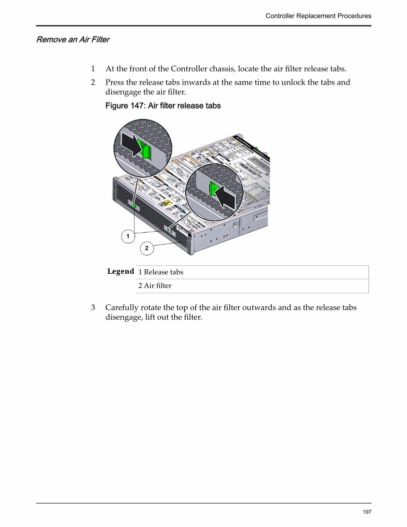
Remove an Air Filter
1 At the front of the Controller chassis, locate the air filter release tabs.
2 Press the release tabs inwards at the same time to unlock the tabs anddisengage the air filter.
Figure 147: Air filter release tabs
Legend 1 Release tabs
2 Air filter
3 Carefully rotate the top of the air filter outwards and as the release tabsdisengage, lift out the filter.
Controller Replacement Procedures
197

Figure 148: Remove air filter
4 Set the air filter aside.
Open the Controller Top Cover
1 Fully loosen the two captive thumb screws at the back of the top coverusing the Phillips number 2 screwdriver, if necessary.
Figure 149: Captive thumb screws to remove the top cover
Legend 1 Controller top cover
2 Captive screws
2 Slide the top cover backwards 0.5 inches (13 mm) and lift the top coverstraight up and off the Controller chassis.
Controller Replacement Procedures
198
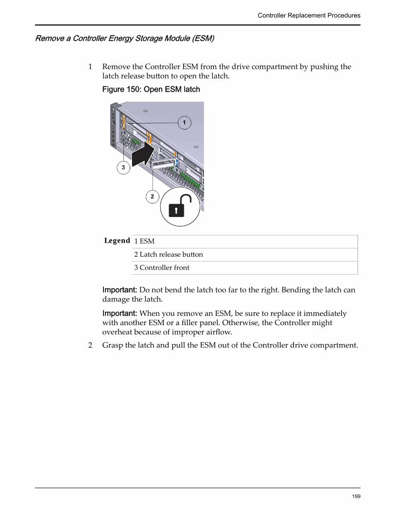
Remove a Controller Energy Storage Module (ESM)
1 Remove the Controller ESM from the drive compartment by pushing thelatch release button to open the latch.
Figure 150: Open ESM latch
Legend 1 ESM
2 Latch release button
3 Controller front
Important: Do not bend the latch too far to the right. Bending the latch candamage the latch.
Important: When you remove an ESM, be sure to replace it immediatelywith another ESM or a filler panel. Otherwise, the Controller mightoverheat because of improper airflow.
2 Grasp the latch and pull the ESM out of the Controller drive compartment.
Controller Replacement Procedures
199
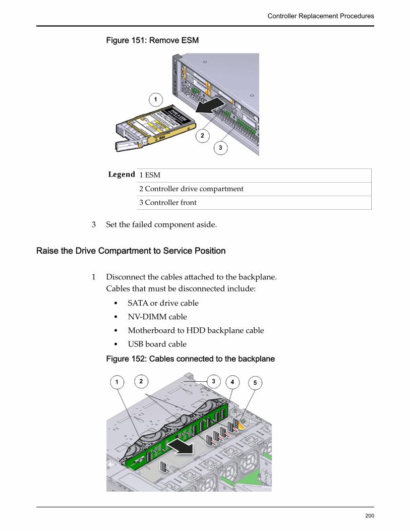
Figure 151: Remove ESM
Legend 1 ESM
2 Controller drive compartment
3 Controller front
3 Set the failed component aside.
Raise the Drive Compartment to Service Position
1 Disconnect the cables attached to the backplane.Cables that must be disconnected include:
• SATA or drive cable
• NV-DIMM cable
• Motherboard to HDD backplane cable
• USB board cable
Figure 152: Cables connected to the backplane
Controller Replacement Procedures
200

Legend 1 SATA or drive cable
2 NV-DIMM cables
3 Drive compartment
4 Backplane boards
5 Motherboard to HDD backplane cable
Note: The USB board cable is connected to the Controller display panel.
Note: All cables attached to the backplane must be disconnected beforeraising the drive compartment. Otherwise, the cables might get damagedor tear due to unnecessary flexure or pull.
Note: Note the location of all the cable connections to the backplane forlater re-connection of the cables after the replacement procedure iscompleted.
Tip: Refer to the service label for more information on rotating the drivecompartment.
2 Disengage the backplane by loosening the four Phillips Number 2 thumbscrews on the four sides of the backplane using a Phillips Number 2screwdriver and rotate the backplane at a 90 degrees angle.
Figure 153: Disengaging the backplane
Legend 1 Thumb screws that secure the backplane
Controller Replacement Procedures
201

2 Backplane
Note: Use the screwdriver very carefully to avoid damaging the electricalcircuitry inside the Controller.
3 Raise the backplane and drive compartment to the vertical position.
Figure 154: Drive compartment raised
Legend 1 Backplane
2 Drive compartment
3 Controller motherboard
Remove a Backplane
1 Remove the five screws that secure the backplane boards to the drivecompartment.
Controller Replacement Procedures
202

Figure 155: Unscrew the backplane boards
Legend 1 Screws securing the backplane boards
2 Backplane board
3 Drive compartment
2 Lift the backplane board off of the alignment pins and out of the Controllerchassis.
Controller Replacement Procedures
203

Figure 156: Remove the backplane boards
Legend 1 Drive compartment
2 Backplane boards
3 Place the backplane on an antistatic mat.
Insert the Backplane
1 Position the backplane boards to where it will install into theControllerReplication Engine chassis.
Controller Replacement Procedures
204
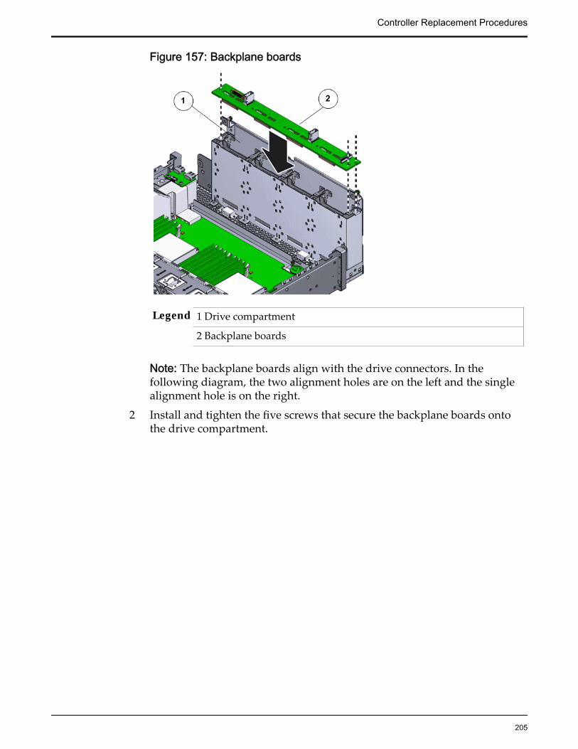
Figure 157: Backplane boards
Legend 1 Drive compartment
2 Backplane boards
Note: The backplane boards align with the drive connectors. In thefollowing diagram, the two alignment holes are on the left and the singlealignment hole is on the right.
2 Install and tighten the five screws that secure the backplane boards ontothe drive compartment.
Controller Replacement Procedures
205

Figure 158: Backplane boards secured
Legend 1 Screws securing the backplane boards
2 Backplane board
3 Drive compartment
3 Secure the backplane inside the Controller by inserting the four PhillipsNumber 2 thumb screws on the four sides of the backplane and tighteningthem using a Phillips Number 2 screwdriver.
4 Rotate the drive compartment and backplane back into position inside theController and ensure that the alignment pins engage.
Note: To confirm that the backplane is locked into position, listen for anaudible click or feel the backplane engage with the Controller.
5 Reconnect all the cables that had been previously disconnected from thebackplane.Cables that must be reconnected include:
• SATA or drive cable
• NV-DIMM cable
• Motherboard to HDD backplane cable
Controller Replacement Procedures
206
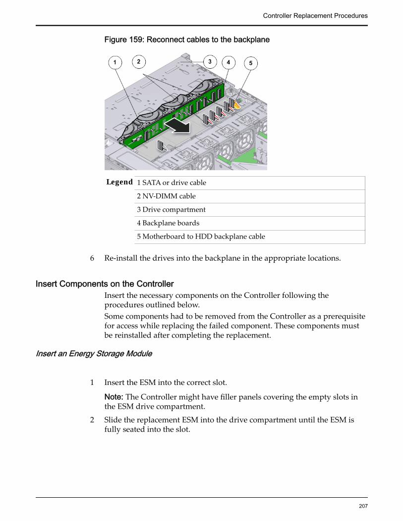
Figure 159: Reconnect cables to the backplane
Legend 1 SATA or drive cable
2 NV-DIMM cable
3 Drive compartment
4 Backplane boards
5 Motherboard to HDD backplane cable
6 Re-install the drives into the backplane in the appropriate locations.
Insert Components on the ControllerInsert the necessary components on the Controller following theprocedures outlined below.Some components had to be removed from the Controller as a prerequisitefor access while replacing the failed component. These components mustbe reinstalled after completing the replacement.
Insert an Energy Storage Module
1 Insert the ESM into the correct slot.
Note: The Controller might have filler panels covering the empty slots inthe ESM drive compartment.
2 Slide the replacement ESM into the drive compartment until the ESM isfully seated into the slot.
Controller Replacement Procedures
207

Figure 160: Insert ESM
Legend 1 ESM
2 Controller drive compartment
3 Controller front
Note: Be sure to install the replacement ESM in the same slot from whichthe ESM was removed.
3 Close the drive carrier latch to lock the ESM in place.
Figure 161: Secure ESM into drive slot
Legend 1 ESM
2 Controller drive compartment
3 Controller front
Note: Do not force the drive carrier latch. You can damage the drive carrierlatch if you apply too much force.
Controller Replacement Procedures
208

Insert an Air Filter
1 Tilt the top of the air filter slightly towards you and insert the bottom twohooks into the mounting tabs.
Figure 162: Insert air filter
Important: Ensure that nothing interferes with the edges of the air filter andthat the air filter seats properly.
2 Press the top corners of the air filter to engage the top two air filter hookswith the top rail tabs.
3 Press both air filter release tabs until they lock in place.
Close the Controller Top Cover
Place the top cover of the Controller and tighten the two thumb screws atthe back of the Controller that secure the top cover.
Controller Replacement Procedures
209

Figure 163: Close Controller top cover
Legend 1 Thumb screws
2 Controller top cover
3 Controller
Complete the Component Replacement
1 Slide the Controller back into rack position.
2 Connect the AC power cords to power on the Controller.
Note: The Controller automatically powers up when the power cords areplugged in.
Verify Controller Component Status
1 From Guided Maintenance, verify that the status is Normal.
You can also verify the status by navigating to System > Hardware andthen selecting a chassis. The Overview page for the selected chassis lists thestatus of each component.
Note: The Controller status will be visible several minutes after beingpowered on.
2 Review the status of the LEDs to confirm a status of Normal.
Controller Replacement Procedures
210

Replace a Controller Heat SinkThe heat sink serves as a cooling device to prevent the CPU in the Controllerfrom overheating. A damaged heat sink can cause the Controller CPU tooverheat, which would cause the CPU to fail. You must replace a damaged heatsink as soon as possible.
CAUTION: Ensure that all power is removed from the Controller before replacingthe heat sink. Disconnect the power cables before performing the heat sinkreplacement procedure.
Prerequisites: • Ensure that you have a Phillips Number 2screwdriver with at least a four-inch shaft.
• Before handling a component, touch a groundedsurface to discharge any static electricity.
• Attach an electrostatic discharge (ESD) wrist strap toyour wrist, and stand on an ESD mat while replacingcomponents.
• Fail over the Controller before replacing thecomponent using Guided Maintenance.
Note: The Controller must be failed over to preventdata loss or data corruption during the componentreplacement process.
Each Controller has two heat sinks located above the CPUs on the Controllermotherboard. Heat sinks are usually durable and need not be replaced. Heatsinks are field replaceable units (FRUs). Replacing a heat sink requires you tobring the Controller offline. The following figure displays the Controller heatsink.
Figure 164: Heat sink
Note: The heat sinks can be accessed only after removing the cover over theController chassis.
Controller Replacement Procedures
211

Note: To replace a heat sink, you do not need to remove the Controller from therack but extend it along the Controller rails.
Procedure Overview
1 Prepare the Component for Replacement
2 Remove the Controller Power Supply Cords
3 Slide Controller to Service Position
4 Open the Controller Top Cover
5 Remove an Air Duct
6 Raise the Drive Compartment to Service Position
7 Remove a Heat Sink
8 Insert a Heat Sink
9 Insert an Air Duct
10 Close the Controller Top Cover
11 Lower the Drive Compartment
12 Complete the Component Replacement
13 Verify Controller Component Status
Related LinksController Components
Prepare the Component for Replacement
1 From Oracle FS System Manager (GUI), navigate to Support > SystemTrouble.
2 Select the Controller that contains the component that is to be replaced.
3 Select Actions > Replace Component.Guided Maintenance displays the list of replaceable components for theController.
Note: Field replaceable units (FRUs) can only be replaced by fieldtechnicians with support role privileges.
4 Select a component from the list.
5 Click Next.
Guided Maintenance displays the Identify Hardware dialog.
6 From the Identify Hardware dialog, specify how you want to identify thechassis so that you can locate it in the data center.
You can select one of the following methods to identify the chassis:
Controller Replacement Procedures
212
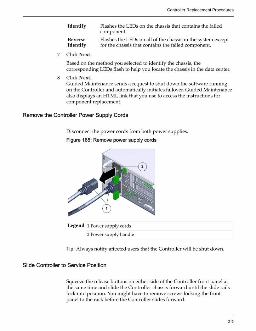
Identify Flashes the LEDs on the chassis that contains the failedcomponent.
ReverseIdentify
Flashes the LEDs on all of the chassis in the system exceptfor the chassis that contains the failed component.
7 Click Next.
Based on the method you selected to identify the chassis, thecorresponding LEDs flash to help you locate the chassis in the data center.
8 Click Next.Guided Maintenance sends a request to shut down the software runningon the Controller and automatically initiates failover. Guided Maintenancealso displays an HTML link that you use to access the instructions forcomponent replacement.
Remove the Controller Power Supply Cords
Disconnect the power cords from both power supplies.
Figure 165: Remove power supply cords
Legend 1 Power supply cords
2 Power supply handle
Tip: Always notify affected users that the Controller will be shut down.
Slide Controller to Service Position
Squeeze the release buttons on either side of the Controller front panel atthe same time and slide the Controller chassis forward until the slide railslock into position. You might have to remove screws locking the frontpanel to the rack before the Controller slides forward.
Controller Replacement Procedures
213
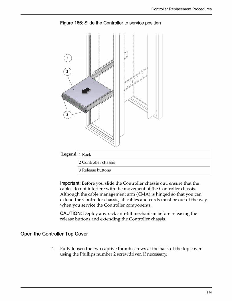
Figure 166: Slide the Controller to service position
Legend 1 Rack
2 Controller chassis
3 Release buttons
Important: Before you slide the Controller chassis out, ensure that thecables do not interfere with the movement of the Controller chassis.Although the cable management arm (CMA) is hinged so that you canextend the Controller chassis, all cables and cords must be out of the waywhen you service the Controller components.
CAUTION: Deploy any rack anti-tilt mechanism before releasing therelease buttons and extending the Controller chassis.
Open the Controller Top Cover
1 Fully loosen the two captive thumb screws at the back of the top coverusing the Phillips number 2 screwdriver, if necessary.
Controller Replacement Procedures
214
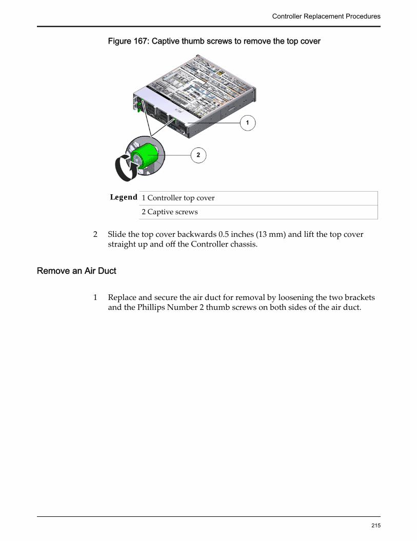
Figure 167: Captive thumb screws to remove the top cover
Legend 1 Controller top cover
2 Captive screws
2 Slide the top cover backwards 0.5 inches (13 mm) and lift the top coverstraight up and off the Controller chassis.
Remove an Air Duct
1 Replace and secure the air duct for removal by loosening the two bracketsand the Phillips Number 2 thumb screws on both sides of the air duct.
Controller Replacement Procedures
215

Figure 168: Remove air duct
Legend 1 Screws that secure air duct
2 Air duct
Note: The brackets that secure the air duct are labeled L (left) and R (right).The left bracket slides forward and the right bracket slides back whenfacing the Controller in the service position.
2 Lift up the air duct from the Controller chassis and set it aside.The following figure shows a Controller air duct:
Figure 169: Air duct
Controller Replacement Procedures
216

Raise the Drive Compartment to Service Position
1 Disconnect the cables attached to the backplane.Cables that must be disconnected include:
• SATA or drive cable
• NV-DIMM cable
• Motherboard to HDD backplane cable
• USB board cable
Figure 170: Cables connected to the backplane
Legend 1 SATA or drive cable
2 NV-DIMM cables
3 Drive compartment
4 Backplane boards
5 Motherboard to HDD backplane cable
Note: The USB board cable is connected to the Controller display panel.
Note: All cables attached to the backplane must be disconnected beforeraising the drive compartment. Otherwise, the cables might get damagedor tear due to unnecessary flexure or pull.
Note: Note the location of all the cable connections to the backplane forlater re-connection of the cables after the replacement procedure iscompleted.
Tip: Refer to the service label for more information on rotating the drivecompartment.
Controller Replacement Procedures
217

2 Disengage the backplane by loosening the four Phillips Number 2 thumbscrews on the four sides of the backplane using a Phillips Number 2screwdriver and rotate the backplane at a 90 degrees angle.
Figure 171: Disengaging the backplane
Legend 1 Thumb screws that secure the backplane
2 Backplane
Note: Use the screwdriver very carefully to avoid damaging the electricalcircuitry inside the Controller.
3 Raise the backplane and drive compartment to the vertical position.
Controller Replacement Procedures
218
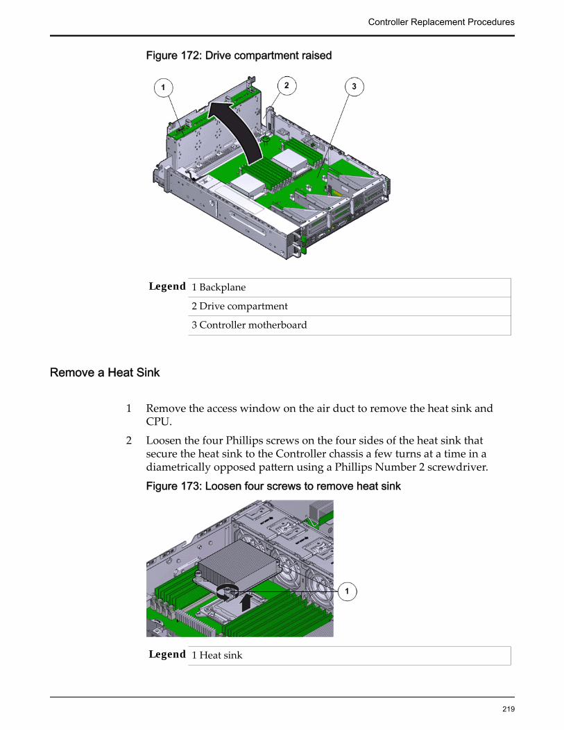
Figure 172: Drive compartment raised
Legend 1 Backplane
2 Drive compartment
3 Controller motherboard
Remove a Heat Sink
1 Remove the access window on the air duct to remove the heat sink andCPU.
2 Loosen the four Phillips screws on the four sides of the heat sink thatsecure the heat sink to the Controller chassis a few turns at a time in adiametrically opposed pattern using a Phillips Number 2 screwdriver.
Figure 173: Loosen four screws to remove heat sink
Legend 1 Heat sink
Controller Replacement Procedures
219
2 Phillips screws that secure the heat sink
Note: Loosen one screw, then loosen the screw opposite that screw on theheat sink to prevent it from warping the motherboard on which it ismounted.
3 Gently twist the heat sink left and right, while pulling upward, to separatethe heat sink from the top of the CPU.
Note: A thin layer of thermal grease separates the heat sink and the CPU.This thermal grease also acts as an adhesive.
CAUTION: Do not allow the thermal grease to contaminate the work spaceor other components.
4 Lift up the failed heat sink and set aside on an antistatic mat.
5 Visually inspect the failed heat sink to verify if the thermal grease hasdried out and use an alcohol pad to clean the thermal grease from theunderside of the heat sink.
Note: Be careful not to get the thermal grease on your fingers, as this couldresult in contamination of components.
CAUTION: Failure to clean the heat sink before removing the CPU canresult in the accidental contamination of the CPU socket or othercomponents.
Insert a Heat Sink
1 Secure the heat sink over the CPU to the Controller motherboard byinserting the four screws on the four sides of the heat sink.
Note: Ensure that the CPU is cleaned with an alcohol pad and freshthermal grease is applied, when installing a new heat sink, to preventoverheating and damage to the CPU.
Important: Ensure that the heat sink and the screws are aligned correctlyand the screws on diagonal ends of the heat sink are tightened first. Aslight force might need to be applied to push down the screwdriver whiletightening the screws to overcome the tension generated.
2 Tighten the four Phillips screws on the heat sink a few turns at a time in adiametrically opposed pattern using a Phillips Number 2 screwdriver.
Controller Replacement Procedures
220
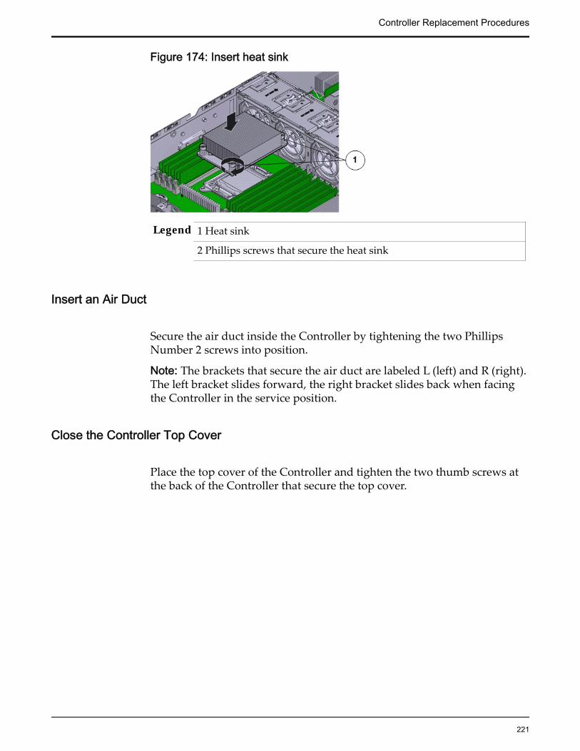
Figure 174: Insert heat sink
Legend 1 Heat sink
2 Phillips screws that secure the heat sink
Insert an Air Duct
Secure the air duct inside the Controller by tightening the two PhillipsNumber 2 screws into position.
Note: The brackets that secure the air duct are labeled L (left) and R (right).The left bracket slides forward, the right bracket slides back when facingthe Controller in the service position.
Close the Controller Top Cover
Place the top cover of the Controller and tighten the two thumb screws atthe back of the Controller that secure the top cover.
Controller Replacement Procedures
221

Figure 175: Close Controller top cover
Legend 1 Thumb screws
2 Controller top cover
3 Controller
Lower the Drive Compartment
1 Rotate the drive compartment and backplane back into position inside theController and ensure that the alignment pins engage.
Note: To confirm that the backplane is locked into position, listen for anaudible click or feel the backplane engage with the Controller.
2 Secure the backplane inside the Controller by inserting the four PhillipsNumber 2 thumb screws on the four sides of the backplane and tighteningthem using a Phillips Number 2 screwdriver.
3 Reconnect all the cables that had been previously disconnected from thebackplane.Cables that must be reconnected include:
• SATA or drive cable
• NV-DIMM cable
• Motherboard to HDD backplane cable
Controller Replacement Procedures
222
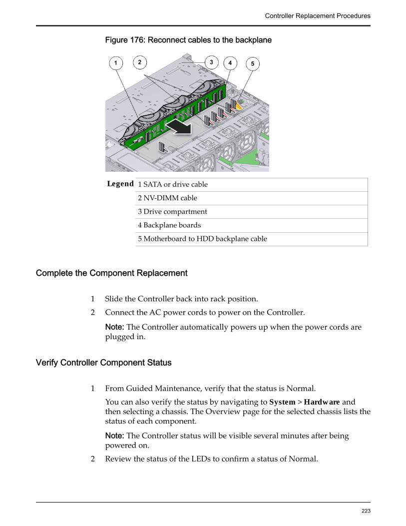
Figure 176: Reconnect cables to the backplane
Legend 1 SATA or drive cable
2 NV-DIMM cable
3 Drive compartment
4 Backplane boards
5 Motherboard to HDD backplane cable
Complete the Component Replacement
1 Slide the Controller back into rack position.
2 Connect the AC power cords to power on the Controller.
Note: The Controller automatically powers up when the power cords areplugged in.
Verify Controller Component Status
1 From Guided Maintenance, verify that the status is Normal.
You can also verify the status by navigating to System > Hardware andthen selecting a chassis. The Overview page for the selected chassis lists thestatus of each component.
Note: The Controller status will be visible several minutes after beingpowered on.
2 Review the status of the LEDs to confirm a status of Normal.
Controller Replacement Procedures
223

Replace a Controller CPUThe CPU provides data computing and processing power to the Controller. Afailed CPU might impact the processing power of the Oracle Flash StorageSystem and must be replaced as soon as possible.
CAUTION: Ensure that all power is removed from the Controller before replacingthe CPU. Disconnect the power cables before performing the CPU replacementprocedure.
Prerequisites: • Ensure that you have a Phillips Number 2screwdriver with at least a four-inch shaft.
• Before handling a component, touch a groundedsurface to discharge any static electricity.
• Attach an electrostatic discharge (ESD) wrist strap toyour wrist, and stand on an ESD mat while replacingcomponents.
• Ensure that you have the thermal grease and syringeavailable to clean the CPU.
• Fail over the Controller before replacing thecomponent using Guided Maintenance.
Note: The Controller must be failed over to preventdata loss or data corruption during the componentreplacement process.
Each Controller has two CPUs located under the two heat sinks inside thechassis. A CPU is a small square component that contains multiple pins orconnectors on the underside and is inserted pin side down into the CPU socketlocated in the motherboard. The CPU is a field replaceable unit (FRU). Replacinga CPU requires you to power down the Controller. The following figure showsthe location of the CPU on the Controller motherboard.
Controller Replacement Procedures
224
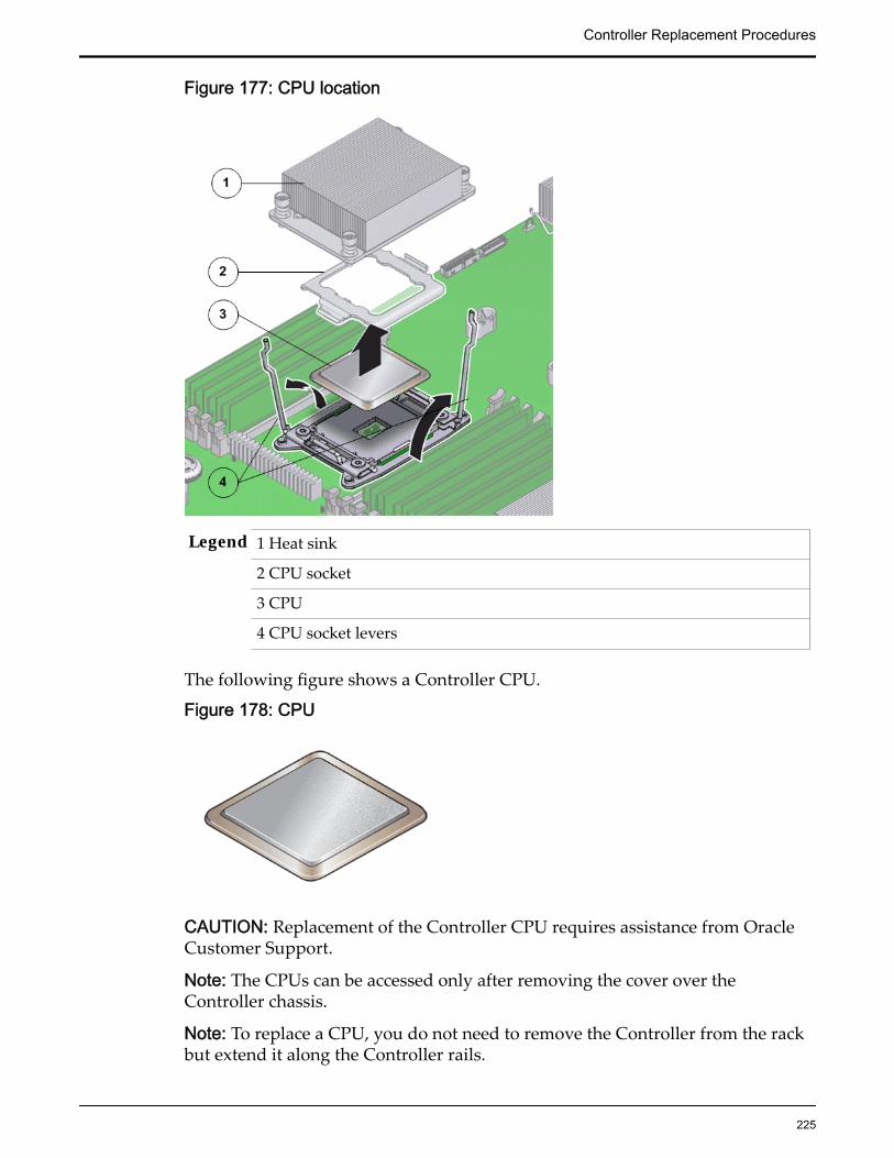
Figure 177: CPU location
Legend 1 Heat sink
2 CPU socket
3 CPU
4 CPU socket levers
The following figure shows a Controller CPU.
Figure 178: CPU
CAUTION: Replacement of the Controller CPU requires assistance from OracleCustomer Support.
Note: The CPUs can be accessed only after removing the cover over theController chassis.
Note: To replace a CPU, you do not need to remove the Controller from the rackbut extend it along the Controller rails.
Controller Replacement Procedures
225
Procedure Overview
1 Prepare the Component for Replacement
2 Remove the Controller Power Supply Cords
3 Slide Controller to Service Position
4 Open the Controller Top Cover
5 Remove an Air Duct
6 Raise the Drive Compartment to Service Position
7 Remove a Heat Sink
8 Remove a CPU
9 Insert a CPU
10 Insert a Heat Sink
11 Close the Controller Top Cover
12 Lower the Drive Compartment
13 Complete the Component Replacement
14 Verify Controller Component Status
Related LinksController Components
Prepare the Component for Replacement1 From Oracle FS System Manager (GUI), navigate to System > Hardware >
Controllers and then select the Controller that contains the component thatis to be replaced.
2 Select Actions > View.
The View dialog displays the components in the Replaceable Unit list. TheStatus column lists the status of each component. A status of Normalrequires no action.
Note: Field replaceable units (FRUs) can only be replaced by fieldtechnicians with support role privileges.
3 Select a component from the list and click Replace Component.
Guided Maintenance displays an image of the chassis.
4 Click Next.
Guided Maintenance displays the Identify Hardware dialog.
5 From the Identify Hardware dialog, specify how you want to identify thechassis so that you can locate it in the data center.
You can select one of the following methods to identify the chassis:
Controller Replacement Procedures
226

Identify Flashes the LEDs on the chassis that contains the failedcomponent.
ReverseIdentify
Flashes the LEDs on all of the chassis in the system exceptfor the chassis that contains the failed component.
6 Click Next.
Based on the method you selected to identify the chassis, thecorresponding LEDs flash to help you locate the chassis in the data center.
7 Click Next.
For components that are not hot-serviceable, Guided Maintenance sends arequest to shut down the software running on the Controller andautomatically initiates failover. Guided Maintenance also displays anHTML link that you use to access the instructions for componentreplacement.
For hot-serviceable components, Guided Maintenance completes theprocess of preparing the system for component replacement and displaysthe Replace Hardware dialog. The Replace Hardware dialog instructs youto replace the component. You also receive a System Alert informing youthat the component is ready for removal. To review System Alerts,navigate to System > Alerts and Events > System Alerts.
Remove the Controller Power Supply Cords
Disconnect the power cords from both power supplies.
Figure 179: Remove power supply cords
Legend 1 Power supply cords
2 Power supply handle
Tip: Always notify affected users that the Controller will be shut down.
Controller Replacement Procedures
227

Slide Controller to Service Position
Squeeze the release buttons on either side of the Controller front panel atthe same time and slide the Controller chassis forward until the slide railslock into position. You might have to remove screws locking the frontpanel to the rack before the Controller slides forward.
Figure 180: Slide the Controller to service position
Legend 1 Rack
2 Controller chassis
3 Release buttons
Important: Before you slide the Controller chassis out, ensure that thecables do not interfere with the movement of the Controller chassis.Although the cable management arm (CMA) is hinged so that you canextend the Controller chassis, all cables and cords must be out of the waywhen you service the Controller components.
CAUTION: Deploy any rack anti-tilt mechanism before releasing therelease buttons and extending the Controller chassis.
Open the Controller Top Cover
Controller Replacement Procedures
228

1 Fully loosen the two captive thumb screws at the back of the top coverusing the Phillips number 2 screwdriver, if necessary.
Figure 181: Captive thumb screws to remove the top cover
Legend 1 Controller top cover
2 Captive screws
2 Slide the top cover backwards 0.5 inches (13 mm) and lift the top coverstraight up and off the Controller chassis.
Remove an Air Duct
1 Replace and secure the air duct for removal by loosening the two bracketsand the Phillips Number 2 thumb screws on both sides of the air duct.
Controller Replacement Procedures
229
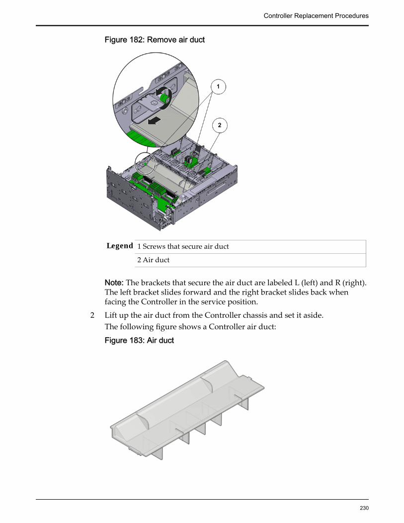
Figure 182: Remove air duct
Legend 1 Screws that secure air duct
2 Air duct
Note: The brackets that secure the air duct are labeled L (left) and R (right).The left bracket slides forward and the right bracket slides back whenfacing the Controller in the service position.
2 Lift up the air duct from the Controller chassis and set it aside.The following figure shows a Controller air duct:
Figure 183: Air duct
Controller Replacement Procedures
230
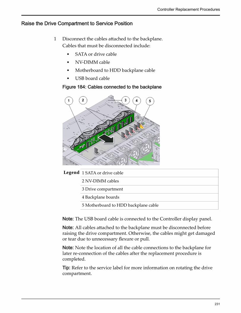
Raise the Drive Compartment to Service Position
1 Disconnect the cables attached to the backplane.Cables that must be disconnected include:
• SATA or drive cable
• NV-DIMM cable
• Motherboard to HDD backplane cable
• USB board cable
Figure 184: Cables connected to the backplane
Legend 1 SATA or drive cable
2 NV-DIMM cables
3 Drive compartment
4 Backplane boards
5 Motherboard to HDD backplane cable
Note: The USB board cable is connected to the Controller display panel.
Note: All cables attached to the backplane must be disconnected beforeraising the drive compartment. Otherwise, the cables might get damagedor tear due to unnecessary flexure or pull.
Note: Note the location of all the cable connections to the backplane forlater re-connection of the cables after the replacement procedure iscompleted.
Tip: Refer to the service label for more information on rotating the drivecompartment.
Controller Replacement Procedures
231

2 Disengage the backplane by loosening the four Phillips Number 2 thumbscrews on the four sides of the backplane using a Phillips Number 2screwdriver and rotate the backplane at a 90 degrees angle.
Figure 185: Disengaging the backplane
Legend 1 Thumb screws that secure the backplane
2 Backplane
Note: Use the screwdriver very carefully to avoid damaging the electricalcircuitry inside the Controller.
3 Raise the backplane and drive compartment to the vertical position.
Controller Replacement Procedures
232

Figure 186: Drive compartment raised
Legend 1 Backplane
2 Drive compartment
3 Controller motherboard
Remove a Heat Sink
1 Remove the access window on the air duct to remove the heat sink andCPU.
2 Loosen the four Phillips screws on the four sides of the heat sink thatsecure the heat sink to the Controller chassis a few turns at a time in adiametrically opposed pattern using a Phillips Number 2 screwdriver.
Figure 187: Loosen four screws to remove heat sink
Legend 1 Heat sink
Controller Replacement Procedures
233

2 Phillips screws that secure the heat sink
Note: Loosen one screw, then loosen the screw opposite that screw on theheat sink to prevent it from warping the motherboard on which it ismounted.
3 Gently twist the heat sink left and right, while pulling upward, to separatethe heat sink from the top of the CPU.
Note: A thin layer of thermal grease separates the heat sink and the CPU.This thermal grease also acts as an adhesive.
CAUTION: Do not allow the thermal grease to contaminate the work spaceor other components.
4 Lift up the failed heat sink and set aside on an antistatic mat.
5 Visually inspect the failed heat sink to verify if the thermal grease hasdried out and use an alcohol pad to clean the thermal grease from theunderside of the heat sink.
Note: Be careful not to get the thermal grease on your fingers, as this couldresult in contamination of components.
CAUTION: Failure to clean the heat sink before removing the CPU canresult in the accidental contamination of the CPU socket or othercomponents.
Remove a CPU
1 Disengage the CPU release lever on the right side of the CPU socket(viewing the Controller from the front) by pushing down and moving it tothe side away from the CPU, and then rotating the lever upward.
Figure 188: Disengage CPU release lever
Legend 1 CPU release lever
Controller Replacement Procedures
234

2 CPU
3 CPU socket
Note: This exposes the CPU inside the CPU socket.
2 Disengage the CPU socket release lever on the left side of the CPU socket(viewing the Controller from the front) by pushing down and moving it tothe side away from the CPU, and then rotating the lever upward.
Figure 189: Disengage CPU socket release lever
Legend 1 CPU socket release lever
2 CPU
3 CPU pressure frame
3 Swing the CPU pressure frame to fully open position and gently disengagethe CPU pins on the underside to lift up the CPU from the CPU socket.
CAUTION: Handle the CPU socket pins with extreme care. CPU socketpins are very fragile. A light touch can bend the CPU socket pins anddamage the board beyond repair.
4 Use the syringe to apply approximately 0.1 ml of thermal grease to the topcenter of the CPU.
CAUTION: Whenever you remove a CPU, you must replace it with anotherCPU and reinstall the heat sink. Otherwise, the Controller might overheatdue to improper airflow.
5 Set aside the failed CPU on an antistatic mat.
Insert a CPU
1 Gently align the underside of the CPU to the pins on the CPU socket andpush down to secure the CPU in the socket.
Controller Replacement Procedures
235

CAUTION: Handle the CPU socket pins with extreme care. CPU socketpins are very fragile. A light touch can bend the CPU socket pins anddamage the board beyond repair.
2 Swing the CPU pressure frame to its fully closed position.
Figure 190: Close CPU pressure frame
Legend 1 CPU release lever
2 CPU
3 CPU pressure frame
3 Push down on the two socket release levers of the CPU socket to secure theCPU inside.
Insert a Heat Sink
1 Secure the heat sink over the CPU to the Controller motherboard byinserting the four screws on the four sides of the heat sink.
Note: Ensure that the CPU is cleaned with an alcohol pad and freshthermal grease is applied, when installing a new heat sink, to preventoverheating and damage to the CPU.
Important: Ensure that the heat sink and the screws are aligned correctlyand the screws on diagonal ends of the heat sink are tightened first. Aslight force might need to be applied to push down the screwdriver whiletightening the screws to overcome the tension generated.
2 Tighten the four Phillips screws on the heat sink a few turns at a time in adiametrically opposed pattern using a Phillips Number 2 screwdriver.
Controller Replacement Procedures
236
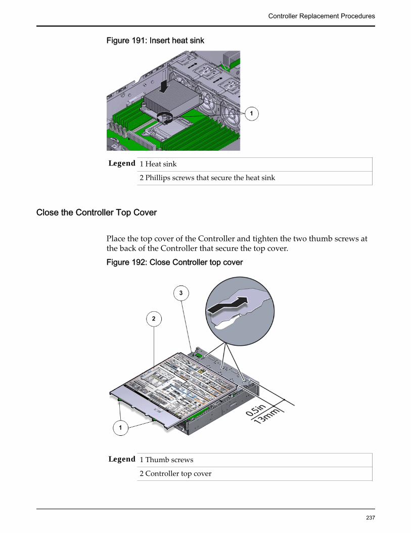
Figure 191: Insert heat sink
Legend 1 Heat sink
2 Phillips screws that secure the heat sink
Close the Controller Top Cover
Place the top cover of the Controller and tighten the two thumb screws atthe back of the Controller that secure the top cover.
Figure 192: Close Controller top cover
Legend 1 Thumb screws
2 Controller top cover
Controller Replacement Procedures
237

3 Controller
Lower the Drive Compartment
1 Rotate the drive compartment and backplane back into position inside theController and ensure that the alignment pins engage.
Note: To confirm that the backplane is locked into position, listen for anaudible click or feel the backplane engage with the Controller.
2 Secure the backplane inside the Controller by inserting the four PhillipsNumber 2 thumb screws on the four sides of the backplane and tighteningthem using a Phillips Number 2 screwdriver.
3 Reconnect all the cables that had been previously disconnected from thebackplane.Cables that must be reconnected include:
• SATA or drive cable
• NV-DIMM cable
• Motherboard to HDD backplane cable
Figure 193: Reconnect cables to the backplane
Legend 1 SATA or drive cable
2 NV-DIMM cable
3 Drive compartment
4 Backplane boards
5 Motherboard to HDD backplane cable
Controller Replacement Procedures
238
Complete the Component Replacement
1 Slide the Controller back into rack position.
2 Connect the AC power cords to power on the Controller.
Note: The Controller automatically powers up when the power cords areplugged in.
Verify Controller Component Status
1 From Guided Maintenance, verify that the status is Normal.
You can also verify the status by navigating to System > Hardware andthen selecting a chassis. The Overview page for the selected chassis lists thestatus of each component.
Note: The Controller status will be visible several minutes after beingpowered on.
2 Review the status of the LEDs to confirm a status of Normal.
Replace a Controller Identification DisplayThe Controller identification display (CUID) displays the unit number of theController. Accurate numbering of the Controller is essential to avoid confusionin the field and a failed CUID must be replaced as soon as possible.
Prerequisites: • Ensure that you have a Phillips Number 2screwdriver with at least a four-inch shaft.
• Before handling a component, touch a groundedsurface to discharge any static electricity.
• Attach an electrostatic discharge (ESD) wrist strap toyour wrist, and stand on an ESD mat while replacingcomponents.
Each Controller has a CUID that is located at the front of the Controller next tothe bezel. The CUID is a customer replaceable unit (CRU). Replacing CUID doesnot require you to bring the Controller offline. The following figure shows theController CUID board.
Controller Replacement Procedures
239
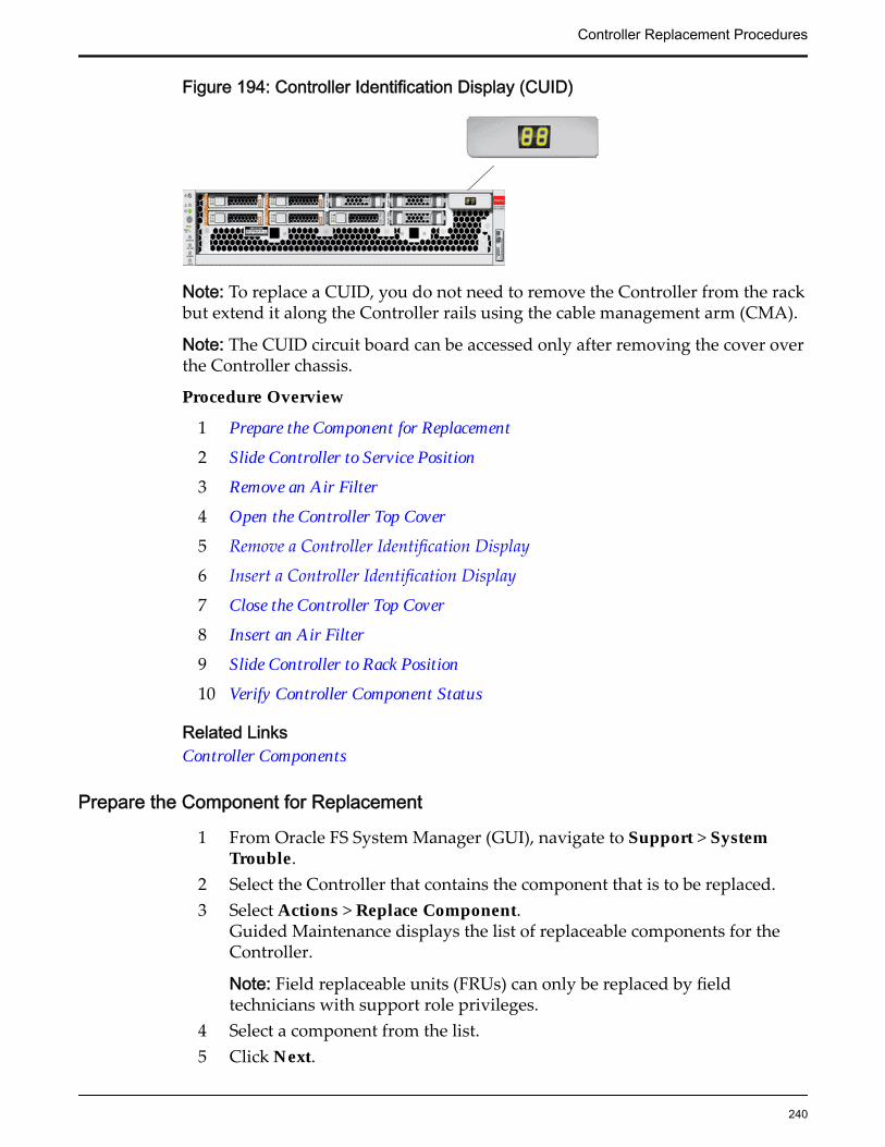
Figure 194: Controller Identification Display (CUID)
Note: To replace a CUID, you do not need to remove the Controller from the rackbut extend it along the Controller rails using the cable management arm (CMA).
Note: The CUID circuit board can be accessed only after removing the cover overthe Controller chassis.
Procedure Overview
1 Prepare the Component for Replacement
2 Slide Controller to Service Position
3 Remove an Air Filter
4 Open the Controller Top Cover
5 Remove a Controller Identification Display
6 Insert a Controller Identification Display
7 Close the Controller Top Cover
8 Insert an Air Filter
9 Slide Controller to Rack Position
10 Verify Controller Component Status
Related LinksController Components
Prepare the Component for Replacement
1 From Oracle FS System Manager (GUI), navigate to Support > SystemTrouble.
2 Select the Controller that contains the component that is to be replaced.3 Select Actions > Replace Component.
Guided Maintenance displays the list of replaceable components for theController.
Note: Field replaceable units (FRUs) can only be replaced by fieldtechnicians with support role privileges.
4 Select a component from the list.5 Click Next.
Controller Replacement Procedures
240

Guided Maintenance displays the Identify Hardware dialog.
6 From the Identify Hardware dialog, specify how you want to identify thechassis so that you can locate it in the data center.
You can select one of the following methods to identify the chassis:
Identify Flashes the LEDs on the chassis that contains the failedcomponent.
ReverseIdentify
Flashes the LEDs on all of the chassis in the system exceptfor the chassis that contains the failed component.
7 Click Next.
Based on the method you selected to identify the chassis, thecorresponding LEDs flash to help you locate the chassis in the data center.
8 Click Next.Guided Maintenance sends a request to shut down the software runningon the Controller and automatically initiates failover. Guided Maintenancealso displays an HTML link that you use to access the instructions forcomponent replacement.
Slide Controller to Service Position
Squeeze the release buttons on either side of the Controller front panel atthe same time and slide the Controller chassis forward until the slide railslock into position. You might have to remove screws locking the frontpanel to the rack before the Controller slides forward.
Controller Replacement Procedures
241
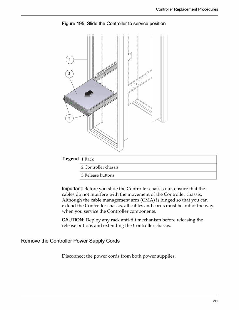
Figure 195: Slide the Controller to service position
Legend 1 Rack
2 Controller chassis
3 Release buttons
Important: Before you slide the Controller chassis out, ensure that thecables do not interfere with the movement of the Controller chassis.Although the cable management arm (CMA) is hinged so that you canextend the Controller chassis, all cables and cords must be out of the waywhen you service the Controller components.
CAUTION: Deploy any rack anti-tilt mechanism before releasing therelease buttons and extending the Controller chassis.
Remove the Controller Power Supply Cords
Disconnect the power cords from both power supplies.
Controller Replacement Procedures
242

Figure 196: Remove power supply cords
Legend 1 Power supply cords
2 Power supply handle
Tip: Always notify affected users that the Controller will be shut down.
Remove an Air Filter
1 At the front of the Controller chassis, locate the air filter release tabs.
2 Press the release tabs inwards at the same time to unlock the tabs anddisengage the air filter.
Figure 197: Air filter release tabs
Legend 1 Release tabs
Controller Replacement Procedures
243

2 Air filter
3 Carefully rotate the top of the air filter outwards and as the release tabsdisengage, lift out the filter.
Figure 198: Remove air filter
4 Set the air filter aside.
Open the Controller Top Cover
1 Fully loosen the two captive thumb screws at the back of the top coverusing the Phillips number 2 screwdriver, if necessary.
Figure 199: Captive thumb screws to remove the top cover
Legend 1 Controller top cover
Controller Replacement Procedures
244

2 Captive screws
2 Slide the top cover backwards 0.5 inches (13 mm) and lift the top coverstraight up and off the Controller chassis.
Remove a Controller Identification Display
1 Disconnect the cable that connects the CUID to the motherboard of theController.
Figure 200: Disconnect the CUID cable
Legend 1 CUID circuit board Number 2 Phillips screw securing the CUID
2 White flexi-cable
3 CUID cable to the motherboard
2 Unscrew the two Phillips Number 2 screws using a Phillips Number 2screwdriver to disengage the CUID circuit board from the display unit.
Controller Replacement Procedures
245
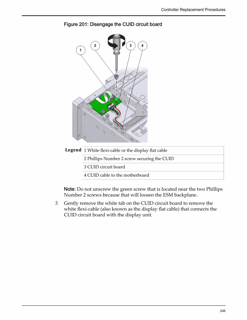
Figure 201: Disengage the CUID circuit board
Legend 1 White flexi-cable or the display flat cable
2 Phillips Number 2 screw securing the CUID
3 CUID circuit board
4 CUID cable to the motherboard
Note: Do not unscrew the green screw that is located near the two PhillipsNumber 2 screws because that will loosen the ESM backplane.
3 Gently remove the white tab on the CUID circuit board to remove thewhite flexi-cable (also known as the display flat cable) that connects theCUID circuit board with the display unit.
Controller Replacement Procedures
246
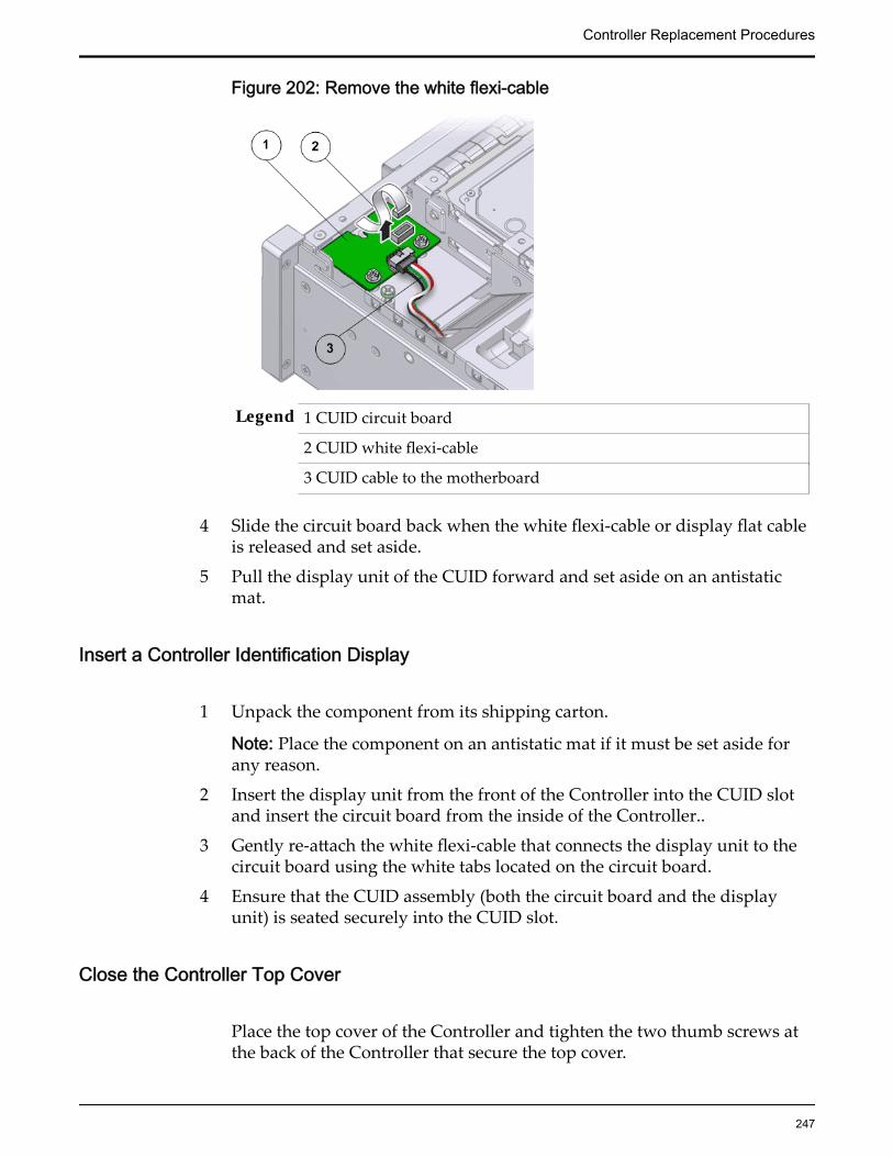
Figure 202: Remove the white flexi-cable
Legend 1 CUID circuit board
2 CUID white flexi-cable
3 CUID cable to the motherboard
4 Slide the circuit board back when the white flexi-cable or display flat cableis released and set aside.
5 Pull the display unit of the CUID forward and set aside on an antistaticmat.
Insert a Controller Identification Display
1 Unpack the component from its shipping carton.
Note: Place the component on an antistatic mat if it must be set aside forany reason.
2 Insert the display unit from the front of the Controller into the CUID slotand insert the circuit board from the inside of the Controller..
3 Gently re-attach the white flexi-cable that connects the display unit to thecircuit board using the white tabs located on the circuit board.
4 Ensure that the CUID assembly (both the circuit board and the displayunit) is seated securely into the CUID slot.
Close the Controller Top Cover
Place the top cover of the Controller and tighten the two thumb screws atthe back of the Controller that secure the top cover.
Controller Replacement Procedures
247

Figure 203: Close Controller top cover
Legend 1 Thumb screws
2 Controller top cover
3 Controller
Power On the Controller
Power on the Controller using the power button and the ILOM webinterface.
Note: As soon as the power cords are connected to the Controller, standbypower is applied. In standby power mode, the Power/OK LED on theController front panel blinks every five seconds or so. However, to applymain power to the Controller, you must use the power button and the webinterface. When main power is applied to the Controller, the green Power/OK LED on the front panel of the Controller blinks steadily. When theController BIOS has completed booting, the OK LED remains lit.
Insert an Air Filter
1 Tilt the top of the air filter slightly towards you and insert the bottom twohooks into the mounting tabs.
Controller Replacement Procedures
248

Figure 204: Insert air filter
Important: Ensure that nothing interferes with the edges of the air filter andthat the air filter seats properly.
2 Press the top corners of the air filter to engage the top two air filter hookswith the top rail tabs.
3 Press both air filter release tabs until they lock in place.
Slide Controller to Rack Position
Slide the Controller back into the rack.
Note: You must release the rail locking mechanism to slide the Controllerchassis back into the rack.
Verify Controller Component Status
1 From Guided Maintenance, verify that the status is Normal.
You can also verify the status by navigating to System > Hardware andthen selecting a chassis. The Overview page for the selected chassis lists thestatus of each component.
Note: The Controller status will be visible several minutes after beingpowered on.
2 Review the status of the LEDs to confirm a status of Normal.
Replace a Controller LED Alarm AssemblyThe LED alarm assembly is a high-level status indicator of the Controller andController components. The LED alarm assembly also includes a power button to
Controller Replacement Procedures
249
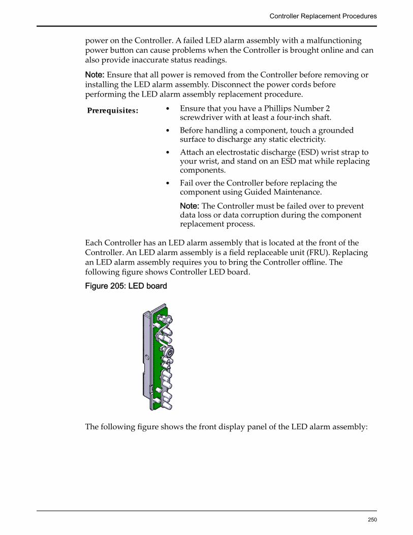
power on the Controller. A failed LED alarm assembly with a malfunctioningpower button can cause problems when the Controller is brought online and canalso provide inaccurate status readings.
Note: Ensure that all power is removed from the Controller before removing orinstalling the LED alarm assembly. Disconnect the power cords beforeperforming the LED alarm assembly replacement procedure.
Prerequisites: • Ensure that you have a Phillips Number 2screwdriver with at least a four-inch shaft.
• Before handling a component, touch a groundedsurface to discharge any static electricity.
• Attach an electrostatic discharge (ESD) wrist strap toyour wrist, and stand on an ESD mat while replacingcomponents.
• Fail over the Controller before replacing thecomponent using Guided Maintenance.
Note: The Controller must be failed over to preventdata loss or data corruption during the componentreplacement process.
Each Controller has an LED alarm assembly that is located at the front of theController. An LED alarm assembly is a field replaceable unit (FRU). Replacingan LED alarm assembly requires you to bring the Controller offline. Thefollowing figure shows Controller LED board.
Figure 205: LED board
The following figure shows the front display panel of the LED alarm assembly:
Controller Replacement Procedures
250

Figure 206: LED assembly front display
Legend 1 Chassis identification LED or LocatorLED
5 Service processor LEDs
2 Service Action Required LED orCaution or Fault LED
6 Rear power supply LED
3 Motherboard or Power or OK LED 7 Fault or Alarm LEDs (Critical,Major, Minor)
4 Power switch 8 User Alarm LED
Note: The LED alarm assembly can be accessed only after removing the coverover the Controller chassis.
Note: Replacement of the Controller LED alarm assembly requires assistancefrom Oracle Customer Support.
Note: To replace an LED alarm assembly, you must remove the Controller fromthe rack and place it on a workbench because the rack rail blocks the screw toremove the LED alarm assembly.
Procedure Overview
1 Prepare the Component for Replacement
2 Remove the Controller Power Supply Cords
3 Disconnect Controller Cabling
4 Slide Controller to Service Position
5 (Optional) Remove Controller Chassis From Rack
6 Remove Components From the Controller
7 Remove an LED Alarm Assembly
Controller Replacement Procedures
251

8 Insert an LED Alarm Assembly
9 Insert Components on the Controller
10 Insert the Controller Onto the Rack
Related LinksController Components
Prepare the Component for Replacement
1 From Oracle FS System Manager (GUI), navigate to Support > SystemTrouble.
2 Select the Controller that contains the component that is to be replaced.
3 Select Actions > Replace Component.Guided Maintenance displays the list of replaceable components for theController.
Note: Field replaceable units (FRUs) can only be replaced by fieldtechnicians with support role privileges.
4 Select a component from the list.
5 Click Next.
Guided Maintenance displays the Identify Hardware dialog.
6 From the Identify Hardware dialog, specify how you want to identify thechassis so that you can locate it in the data center.
You can select one of the following methods to identify the chassis:
Identify Flashes the LEDs on the chassis that contains the failedcomponent.
ReverseIdentify
Flashes the LEDs on all of the chassis in the system exceptfor the chassis that contains the failed component.
7 Click Next.
Based on the method you selected to identify the chassis, thecorresponding LEDs flash to help you locate the chassis in the data center.
8 Click Next.Guided Maintenance sends a request to shut down the software runningon the Controller and automatically initiates failover. Guided Maintenancealso displays an HTML link that you use to access the instructions forcomponent replacement.
Remove the Controller Power Supply Cords
Disconnect the power cords from both power supplies.
Controller Replacement Procedures
252

Figure 207: Remove power supply cords
Legend 1 Power supply cords
2 Power supply handle
Tip: Always notify affected users that the Controller will be shut down.
Slide Controller to Service Position
Squeeze the release buttons on either side of the Controller front panel atthe same time and slide the Controller chassis forward until the slide railslock into position. You might have to remove screws locking the frontpanel to the rack before the Controller slides forward.
Controller Replacement Procedures
253

Figure 208: Slide the Controller to service position
Legend 1 Rack
2 Controller chassis
3 Release buttons
Important: Before you slide the Controller chassis out, ensure that thecables do not interfere with the movement of the Controller chassis.Although the cable management arm (CMA) is hinged so that you canextend the Controller chassis, all cables and cords must be out of the waywhen you service the Controller components.
CAUTION: Deploy any rack anti-tilt mechanism before releasing therelease buttons and extending the Controller chassis.
(Optional) Remove Controller Chassis From Rack
1 From the front of the Controller, press on the slide-rail release tabs on bothsides at the front of the Controller, and pull the Controller out of the rackuntil is free of the rack rails.
Important: Oracle recommends not removing the Controller from the railsfor servicing the components. All components are designed for
Controller Replacement Procedures
254

replacement and servicing while the Controller chassis is on the rails.However, if you must remove the Controller from the rack, disconnect therear panel Controller cables from the front with the Controller in serviceposition.
Note: A slide-rail release tab is located on each slide-rail of the Controller.
2 With the help of a partner or a mechanical lift, place the Controller on anantistatic surface on a workbench.
Remove Components From the Controller
Note: Some components must be removed from the Controller as a prerequisitefor access while replacing the failed component.
Note: All components that are removed from the Controller must be placed on anantistatic surface or ESD qualified mat.
Open the Controller Top Cover
1 Fully loosen the two captive thumb screws at the back of the top coverusing the Phillips number 2 screwdriver, if necessary.
Figure 209: Captive thumb screws to remove the top cover
Legend 1 Controller top cover
2 Captive screws
2 Slide the top cover backwards 0.5 inches (13 mm) and lift the top coverstraight up and off the Controller chassis.
Controller Replacement Procedures
255

Remove an Air Filter
1 At the front of the Controller chassis, locate the air filter release tabs.
2 Press the release tabs inwards at the same time to unlock the tabs anddisengage the air filter.
Figure 210: Air filter release tabs
Legend 1 Release tabs
2 Air filter
3 Carefully rotate the top of the air filter outwards and as the release tabsdisengage, lift out the filter.
Controller Replacement Procedures
256
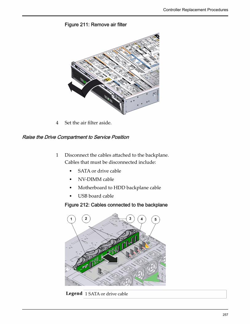
Figure 211: Remove air filter
4 Set the air filter aside.
Raise the Drive Compartment to Service Position
1 Disconnect the cables attached to the backplane.Cables that must be disconnected include:
• SATA or drive cable
• NV-DIMM cable
• Motherboard to HDD backplane cable
• USB board cable
Figure 212: Cables connected to the backplane
Legend 1 SATA or drive cable
Controller Replacement Procedures
257

2 NV-DIMM cables
3 Drive compartment
4 Backplane boards
5 Motherboard to HDD backplane cable
Note: The USB board cable is connected to the Controller display panel.
Note: All cables attached to the backplane must be disconnected beforeraising the drive compartment. Otherwise, the cables might get damagedor tear due to unnecessary flexure or pull.
Note: Note the location of all the cable connections to the backplane forlater re-connection of the cables after the replacement procedure iscompleted.
Tip: Refer to the service label for more information on rotating the drivecompartment.
2 Disengage the backplane by loosening the four Phillips Number 2 thumbscrews on the four sides of the backplane using a Phillips Number 2screwdriver and rotate the backplane at a 90 degrees angle.
Figure 213: Disengaging the backplane
Legend 1 Thumb screws that secure the backplane
2 Backplane
Controller Replacement Procedures
258
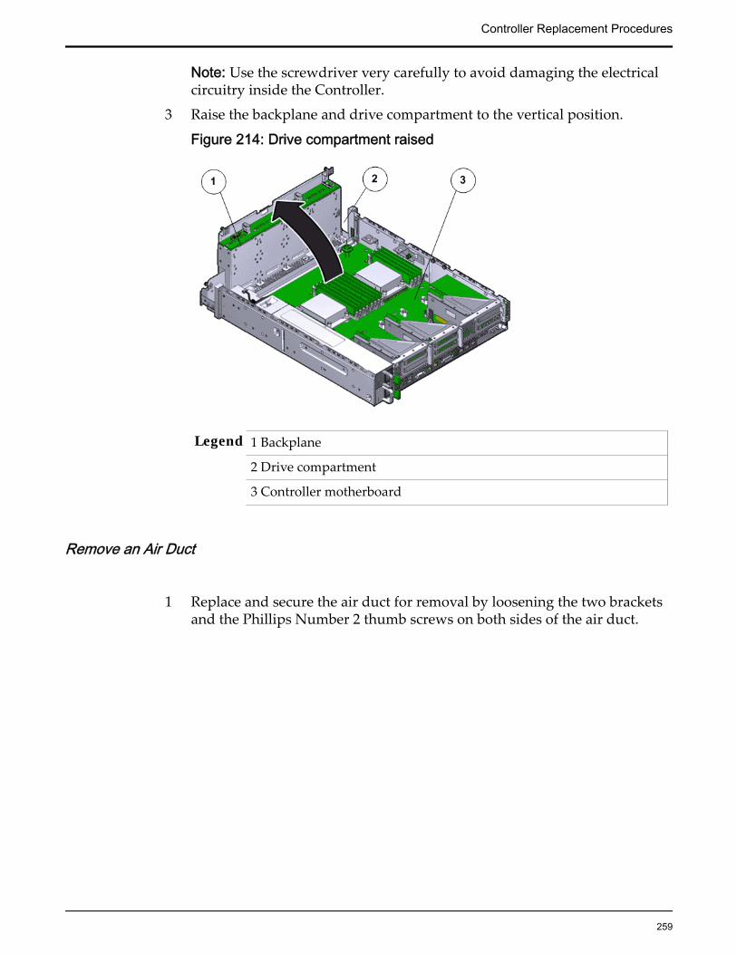
Note: Use the screwdriver very carefully to avoid damaging the electricalcircuitry inside the Controller.
3 Raise the backplane and drive compartment to the vertical position.
Figure 214: Drive compartment raised
Legend 1 Backplane
2 Drive compartment
3 Controller motherboard
Remove an Air Duct
1 Replace and secure the air duct for removal by loosening the two bracketsand the Phillips Number 2 thumb screws on both sides of the air duct.
Controller Replacement Procedures
259

Figure 215: Remove air duct
Legend 1 Screws that secure air duct
2 Air duct
Note: The brackets that secure the air duct are labeled L (left) and R (right).The left bracket slides forward and the right bracket slides back whenfacing the Controller in the service position.
2 Lift up the air duct from the Controller chassis and set it aside.The following figure shows a Controller air duct:
Figure 216: Air duct
Controller Replacement Procedures
260

Remove an LED Alarm Assembly
1 Disconnect the cable from the cable clamp on the the side wall of theController chassis.
2 Disconnect the cable from the motherboard.
Figure 217: Disconnect the LED alarm assembly cable
Legend 1 LED alarm assembly cable
3 Unscrew the two Phillips Number 2 screws at the back of the LED alarmassembly that secure the LED assembly to the Controller front panel.
Figure 218: Screws to secure the LED alarm assembly
Legend 1 LED assembly
2 Controller chassis
3 Screws that secure the LED assembly to chassis
Controller Replacement Procedures
261
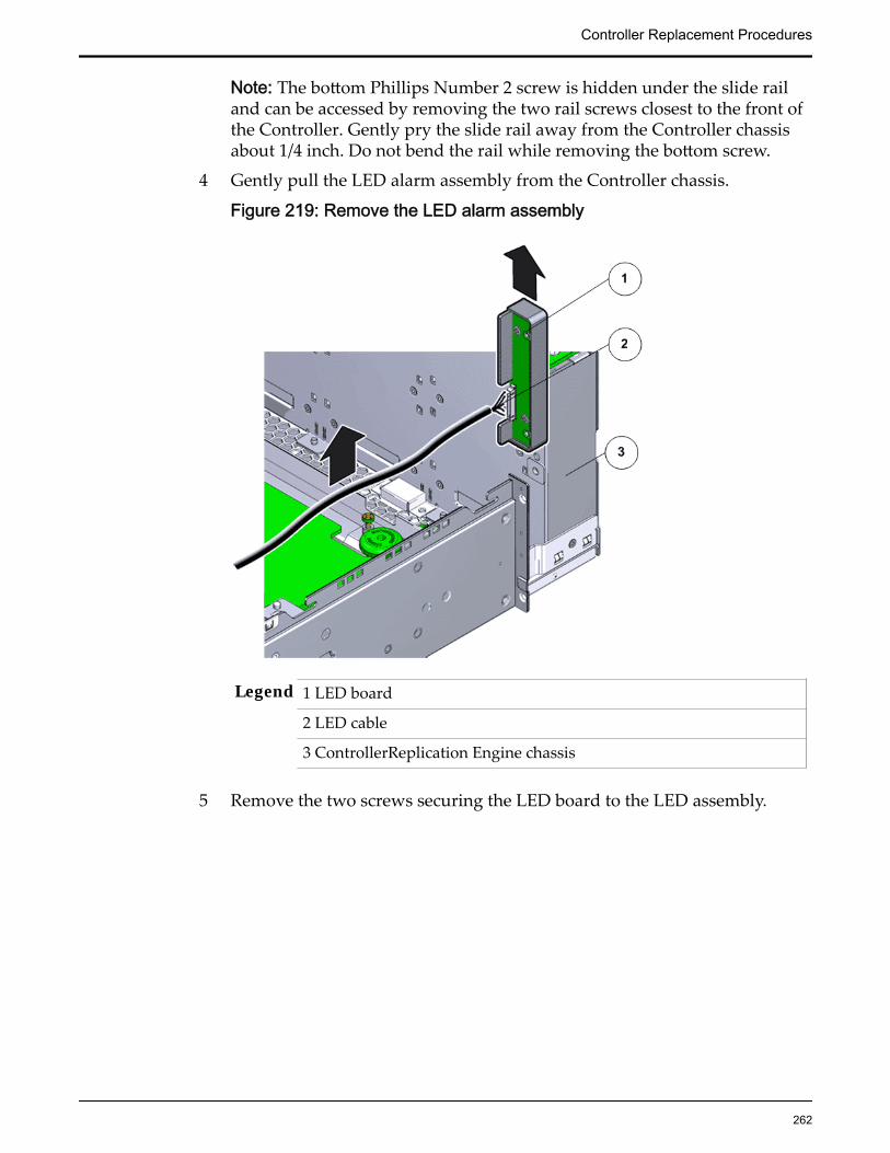
Note: The bottom Phillips Number 2 screw is hidden under the slide railand can be accessed by removing the two rail screws closest to the front ofthe Controller. Gently pry the slide rail away from the Controller chassisabout 1/4 inch. Do not bend the rail while removing the bottom screw.
4 Gently pull the LED alarm assembly from the Controller chassis.
Figure 219: Remove the LED alarm assembly
Legend 1 LED board
2 LED cable
3 ControllerReplication Engine chassis
5 Remove the two screws securing the LED board to the LED assembly.
Controller Replacement Procedures
262

Figure 220: Detach LED board from the LED alarm assembly
Legend 1 LED alarm assembly
2 Screws securing the LED board to the LED alarm assembly
3 LED board
6 Lift the LED board from the LED assembly and set it aside.
Insert an LED Alarm Assembly
1 Unpack the component from its shipping carton.
Note: Place the component on an antistatic mat if it must be set aside forany reason.
2 Set the LED board into the LED assembly.
Controller Replacement Procedures
263

Figure 221: Detach LED board from the LED alarm assembly
Legend 1 LED alarm assembly
2 Screws securing the LED board to the LED alarm assembly
3 LED board
3 Install and tighten the two screws.
4 Position the LED assembly over the flange on the left of the Controllerchassis.
Controller Replacement Procedures
264

Figure 222: LED alarm assembly positioned over Controller chassis
Legend 1 LED board
2 LED cable
3 Controller chassis
5 Install and tighten the two screws to secure the LED alarm assembly ontothe Controller chassis.
Figure 223: Screws to secure the LED alarm assembly
Legend 1 LED assembly
Controller Replacement Procedures
265

2 Controller chassis
3 Screws that secure the LED assembly to chassis
Note: The bottom Phillips Number 2 screw is hidden under the slide railand can be accessed by removing the two rail screws closest to the front ofthe Controller. Gently pry the slide rail away from the Controller chassisabout 1/4 inch. Do not bend the rail while removing the bottom screw.
6 Route the cable into the cable clamp against the side wall and the midplaneof the Controller chassis.
7 Gently connect the cable to the motherboard.
Figure 224: Reconnect LED alarm assembly cable
8 Insert and tighten the two Phillips Number 2 screws at the back of the LEDalarm assembly and secure the LED assembly to the ControllerReplicationEngine front panel.
Insert Components on the ControllerInsert the necessary components on the Controller following theprocedures outlined below.Some components had to be removed from the Controller as a prerequisitefor access while replacing the failed component. These components mustbe reinstalled after completing the replacement.
Insert an Air Duct
Secure the air duct inside the Controller by tightening the two PhillipsNumber 2 screws into position.
Note: The brackets that secure the air duct are labeled L (left) and R (right).The left bracket slides forward, the right bracket slides back when facingthe Controller in the service position.
Controller Replacement Procedures
266
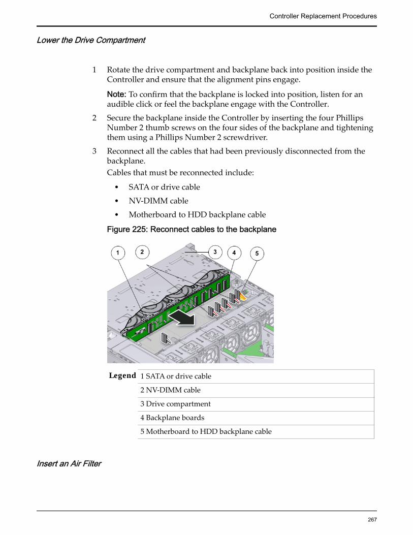
Lower the Drive Compartment
1 Rotate the drive compartment and backplane back into position inside theController and ensure that the alignment pins engage.
Note: To confirm that the backplane is locked into position, listen for anaudible click or feel the backplane engage with the Controller.
2 Secure the backplane inside the Controller by inserting the four PhillipsNumber 2 thumb screws on the four sides of the backplane and tighteningthem using a Phillips Number 2 screwdriver.
3 Reconnect all the cables that had been previously disconnected from thebackplane.Cables that must be reconnected include:
• SATA or drive cable
• NV-DIMM cable
• Motherboard to HDD backplane cable
Figure 225: Reconnect cables to the backplane
Legend 1 SATA or drive cable
2 NV-DIMM cable
3 Drive compartment
4 Backplane boards
5 Motherboard to HDD backplane cable
Insert an Air Filter
Controller Replacement Procedures
267

1 Tilt the top of the air filter slightly towards you and insert the bottom twohooks into the mounting tabs.
Figure 226: Insert air filter
Important: Ensure that nothing interferes with the edges of the air filter andthat the air filter seats properly.
2 Press the top corners of the air filter to engage the top two air filter hookswith the top rail tabs.
3 Press both air filter release tabs until they lock in place.
Close the Controller Top Cover
Place the top cover of the Controller and tighten the two thumb screws atthe back of the Controller that secure the top cover.
Controller Replacement Procedures
268

Figure 227: Close Controller top cover
Legend 1 Thumb screws
2 Controller top cover
3 Controller
Insert the Controller Onto the Rack
Insert the Controller into the rack.Inserting the Controller onto the rack includes the following tasks:
1 Lift up the Controller Onto the Rack
2 Slide the Controller back into Rack position.
3 Reconnect the Controller cabling and the CMA.
4 Power on the Controller.
5 Verify the ControllerReplication Engine component status.
Insert Controller Chassis Onto Rack
With the help of a partner or a mechanical lift, engage the Controller withthe rack rails.
Controller Replacement Procedures
269

CAUTION: Do not use the power supply handles to lift the Controller.Using the power supply handles to lift the Controller can damage thepower supplies and disrupt electrical power to the
Slide Controller to Rack Position
Slide the Controller back into the rack.
Note: You must release the rail locking mechanism to slide the Controllerchassis back into the rack.
Power On the Controller
Power on the Controller using the power button and the ILOM webinterface.
Note: As soon as the power cords are connected to the Controller, standbypower is applied. In standby power mode, the Power/OK LED on theController front panel blinks every five seconds or so. However, to applymain power to the Controller, you must use the power button and the webinterface. When main power is applied to the Controller, the green Power/OK LED on the front panel of the Controller blinks steadily. When theController BIOS has completed booting, the OK LED remains lit.
Verify Controller Component Status
1 From Guided Maintenance, verify that the status is Normal.
You can also verify the status by navigating to System > Hardware andthen selecting a chassis. The Overview page for the selected chassis lists thestatus of each component.
Note: The Controller status will be visible several minutes after beingpowered on.
2 Review the status of the LEDs to confirm a status of Normal.
Replace a Controller MotherboardThe motherboard is the primary circuit board of the Controller. All Controllercomponents are connected to the motherboard using electrical circuits andcommunicate with the motherboard to ensure normal Controller operation. A
Controller Replacement Procedures
270
failed motherboard can cause the Controller to fail and must be replaced as soonas possible.
Prerequisites: • Ensure that you have a Phillips Number 2screwdriver with at least a four-inch shaft.
• Before handling a component, touch a groundedsurface to discharge any static electricity.
• Attach an electrostatic discharge (ESD) wrist strap toyour wrist, and stand on an ESD mat while replacingcomponents.
• Ensure that there is a workbench available to placethe Controller chassis if it is removed from the rackfor servicing.
• Ensure that you have thermal grease and syringeavailable to clean the CPU and heat sink during thereplacement procedure.
• Make sure that you have a Torx Number 10screwdriver.
• Ensure that there is a static protected surface orworkbench available to place the componentstemporarily when they are removed from themotherboard during the replacement process.
• Fail over the Controller before replacing thecomponent using Guided Maintenance.
Note: The Controller must be failed over to preventdata loss or data corruption during the componentreplacement process.
Each Controller has a motherboard that is located on a tray at the bottom of thechassis. The Controller motherboard is a field replaceable unit (FRU) on whichthe various Controller components (FRUs and CRUs) are located. Replacing amotherboard requires you to bring the Controller offline. The following figureshows the Controller motherboard.
Controller Replacement Procedures
271
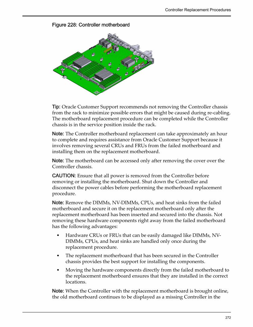
Figure 228: Controller motherboard
Tip: Oracle Customer Support recommends not removing the Controller chassisfrom the rack to minimize possible errors that might be caused during re-cabling.The motherboard replacement procedure can be completed while the Controllerchassis is in the service position inside the rack.
Note: The Controller motherboard replacement can take approximately an hourto complete and requires assistance from Oracle Customer Support because itinvolves removing several CRUs and FRUs from the failed motherboard andinstalling them on the replacement motherboard.
Note: The motherboard can be accessed only after removing the cover over theController chassis.
CAUTION: Ensure that all power is removed from the Controller beforeremoving or installing the motherboard. Shut down the Controller anddisconnect the power cables before performing the motherboard replacementprocedure.
Note: Remove the DIMMs, NV-DIMMs, CPUs, and heat sinks from the failedmotherboard and secure it on the replacement motherboard only after thereplacement motherboard has been inserted and secured into the chassis. Notremoving these hardware components right away from the failed motherboardhas the following advantages:
• Hardware CRUs or FRUs that can be easily damaged like DIMMs, NV-DIMMs, CPUs, and heat sinks are handled only once during thereplacement procedure.
• The replacement motherboard that has been secured in the Controllerchassis provides the best support for installing the components.
• Moving the hardware components directly from the failed motherboard tothe replacement motherboard ensures that they are installed in the correctlocations.
Note: When the Controller with the replacement motherboard is brought online,the old motherboard continues to be displayed as a missing Controller in the
Controller Replacement Procedures
272
GUI for a brief span of time (approximately 20 minutes) until the Controller withthe replacement motherboard is fully initialized.
Procedure Overview
1 Prepare the Component for Replacement
2 Remove the Controller Power Supply Cords
3 Slide Controller to Service Position
4 Disconnect Controller Cabling
5 (Optional) Remove Controller Chassis From Rack
6 Remove Components From the Controller
7 Insert Components on the Controller
8 Reconnect Controller Cabling
9 Slide Controller to Rack Position
10 Power On the Controller
11 Verify Controller Component Status
12 Update the Controller BIOS
Related LinksController Components
Prepare the Component for Replacement1 From Oracle FS System Manager (GUI), navigate to System > Hardware >
Controllers and then select the Controller that contains the component thatis to be replaced.
2 Select Actions > View.
The View dialog displays the components in the Replaceable Unit list. TheStatus column lists the status of each component. A status of Normalrequires no action.
Note: Field replaceable units (FRUs) can only be replaced by fieldtechnicians with support role privileges.
3 Select a component from the list and click Replace Component.
Guided Maintenance displays an image of the chassis.
4 Click Next.
Guided Maintenance displays the Identify Hardware dialog.
5 From the Identify Hardware dialog, specify how you want to identify thechassis so that you can locate it in the data center.
You can select one of the following methods to identify the chassis:
Controller Replacement Procedures
273
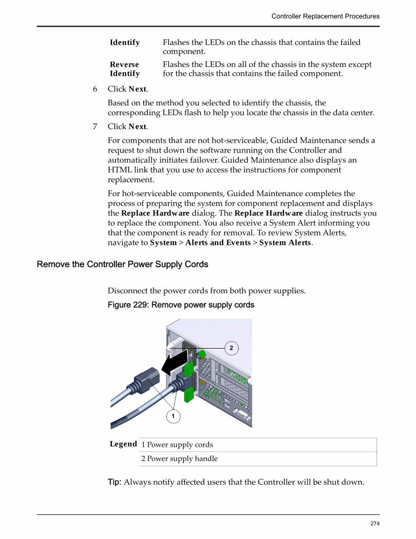
Identify Flashes the LEDs on the chassis that contains the failedcomponent.
ReverseIdentify
Flashes the LEDs on all of the chassis in the system exceptfor the chassis that contains the failed component.
6 Click Next.
Based on the method you selected to identify the chassis, thecorresponding LEDs flash to help you locate the chassis in the data center.
7 Click Next.
For components that are not hot-serviceable, Guided Maintenance sends arequest to shut down the software running on the Controller andautomatically initiates failover. Guided Maintenance also displays anHTML link that you use to access the instructions for componentreplacement.
For hot-serviceable components, Guided Maintenance completes theprocess of preparing the system for component replacement and displaysthe Replace Hardware dialog. The Replace Hardware dialog instructs youto replace the component. You also receive a System Alert informing youthat the component is ready for removal. To review System Alerts,navigate to System > Alerts and Events > System Alerts.
Remove the Controller Power Supply Cords
Disconnect the power cords from both power supplies.
Figure 229: Remove power supply cords
Legend 1 Power supply cords
2 Power supply handle
Tip: Always notify affected users that the Controller will be shut down.
Controller Replacement Procedures
274

Slide Controller to Service Position
Squeeze the release buttons on either side of the Controller front panel atthe same time and slide the Controller chassis forward until the slide railslock into position. You might have to remove screws locking the frontpanel to the rack before the Controller slides forward.
Figure 230: Slide the Controller to service position
Legend 1 Rack
2 Controller chassis
3 Release buttons
Important: Before you slide the Controller chassis out, ensure that thecables do not interfere with the movement of the Controller chassis.Although the cable management arm (CMA) is hinged so that you canextend the Controller chassis, all cables and cords must be out of the waywhen you service the Controller components.
CAUTION: Deploy any rack anti-tilt mechanism before releasing therelease buttons and extending the Controller chassis.
Disconnect Controller Cabling
Controller Replacement Procedures
275
Disconnect all data cables from the Controller.
Note: All cables must be dis-connected from the Controller and labelledsuch that they can be reconnected accurately to the Controller after thereplacement procedure is complete. Reconnecting cables to the incorrectposition might impact the performance of the Controller or result in acomplete loss of functionality.
Note: Service the Controller components from the front of the Controllerwhile the Controller is in service position.
Note: Do not lean on or place any weight on the Controller while theController is in the service position.
(Optional) Remove Controller Chassis From Rack
1 From the front of the Controller, press on the slide-rail release tabs on bothsides at the front of the Controller, and pull the Controller out of the rackuntil is free of the rack rails.
Important: Oracle recommends not removing the Controller from the railsfor servicing the components. All components are designed forreplacement and servicing while the Controller chassis is on the rails.However, if you must remove the Controller from the rack, disconnect therear panel Controller cables from the front with the Controller in serviceposition.
Note: A slide-rail release tab is located on each slide-rail of the Controller.
2 With the help of a partner or a mechanical lift, place the Controller on anantistatic surface on a workbench.
Remove Components From the Controller
Note: Some components must be removed from the Controller as a prerequisitefor access while replacing the failed component.
Note: All components that are removed from the Controller must be placed on anantistatic surface or ESD qualified mat.
Open the Controller Top Cover
1 Fully loosen the two captive thumb screws at the back of the top coverusing the Phillips number 2 screwdriver, if necessary.
Controller Replacement Procedures
276

Figure 231: Captive thumb screws to remove the top cover
Legend 1 Controller top cover
2 Captive screws
2 Slide the top cover backwards 0.5 inches (13 mm) and lift the top coverstraight up and off the Controller chassis.
Remove an Air Filter1 At the front of the Controller chassis, locate the air filter release tabs.2 Press the release tabs inwards at the same time to unlock the tabs and
disengage the air filter.
Figure 232: Air filter release tabs
Legend 1 Release tabs
Controller Replacement Procedures
277

2 Air filter
3 Carefully rotate the top of the air filter outwards and as the release tabsdisengage, lift out the filter.
Figure 233: Remove air filter
4 Set the air filter aside.
Remove a Fan Module
1 Using your thumb and forefinger, grasp the removal tab and gently lift thefan module from the fan compartment.
Controller Replacement Procedures
278
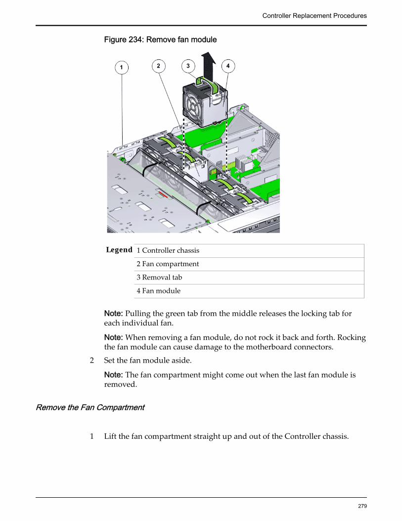
Figure 234: Remove fan module
Legend 1 Controller chassis
2 Fan compartment
3 Removal tab
4 Fan module
Note: Pulling the green tab from the middle releases the locking tab foreach individual fan.
Note: When removing a fan module, do not rock it back and forth. Rockingthe fan module can cause damage to the motherboard connectors.
2 Set the fan module aside.
Note: The fan compartment might come out when the last fan module isremoved.
Remove the Fan Compartment
1 Lift the fan compartment straight up and out of the Controller chassis.
Controller Replacement Procedures
279

Figure 235: Remove fan compartment
Legend 1 ControllerReplication Engine chassis
2 Fan compartment
Note: All fan modules must be removed from the fan compartment beforeremoving the fan compartment.
2 Set the component aside.
Remove an Air Duct
1 Replace and secure the air duct for removal by loosening the two bracketsand the Phillips Number 2 thumb screws on both sides of the air duct.
Controller Replacement Procedures
280

Figure 236: Remove air duct
Legend 1 Screws that secure air duct
2 Air duct
Note: The brackets that secure the air duct are labeled L (left) and R (right).The left bracket slides forward and the right bracket slides back whenfacing the Controller in the service position.
2 Lift up the air duct from the Controller chassis and set it aside.The following figure shows a Controller air duct:
Figure 237: Air duct
Controller Replacement Procedures
281

Raise the Drive Compartment to Service Position1 Disconnect the cables attached to the backplane.
Cables that must be disconnected include:
• SATA or drive cable
• NV-DIMM cable
• Motherboard to HDD backplane cable
• USB board cable
Figure 238: Cables connected to the backplane
Legend 1 SATA or drive cable
2 NV-DIMM cables
3 Drive compartment
4 Backplane boards
5 Motherboard to HDD backplane cable
Note: The USB board cable is connected to the Controller display panel.
Note: All cables attached to the backplane must be disconnected beforeraising the drive compartment. Otherwise, the cables might get damagedor tear due to unnecessary flexure or pull.
Note: Note the location of all the cable connections to the backplane forlater re-connection of the cables after the replacement procedure iscompleted.
Tip: Refer to the service label for more information on rotating the drivecompartment.
2 Disengage the backplane by loosening the four Phillips Number 2 thumbscrews on the four sides of the backplane using a Phillips Number 2screwdriver and rotate the backplane at a 90 degrees angle.
Controller Replacement Procedures
282
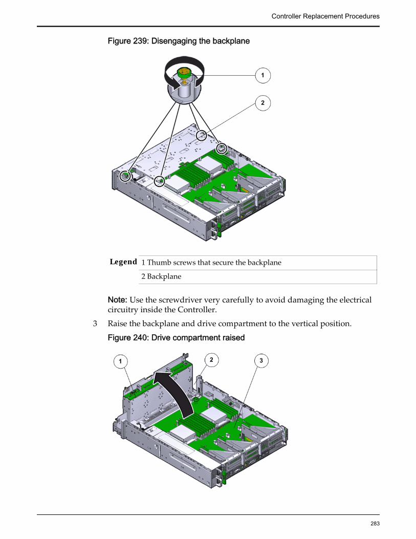
Figure 239: Disengaging the backplane
Legend 1 Thumb screws that secure the backplane
2 Backplane
Note: Use the screwdriver very carefully to avoid damaging the electricalcircuitry inside the Controller.
3 Raise the backplane and drive compartment to the vertical position.
Figure 240: Drive compartment raised
Controller Replacement Procedures
283

Legend 1 Backplane
2 Drive compartment
3 Controller motherboard
Remove a Riser
1 Disconnect any external cables that remain connected to the HBAs in therisers.
Note: Also disconnect any internal cables attached to the HBAs, if that willease removing the HBA.
Tip: Make a note of the positions of all existing cable connections beforeremoving any cables. Replacing HBAs or their cables into the incorrectposition in the riser may result in a loss of performance or functionality.
2 Note the position of the HBAs installed on the riser.
Tip: Make a note of the slot numbers of all existing HBAs before removingany HBAs.
3 Using a Phillips Number 2 screwdriver, loosen the two Phillips Number 2captive screws on either side of the riser that hold the riser to theController motherboard.
Note: The riser on the opposite end of the power supply has a latch thatmust be disengaged to remove the riser from the Controller chassis
Controller Replacement Procedures
284

Figure 241: Captive screws to secure the risers
Legend 1 Riser 3 with latch 3 Riser 1
2 Riser 2 4 Captive screws that secure riser
To remove riser 3, unlock the latch to release the riser from the Controllermotherboard.
Figure 242: Unlock Riser 3 latch
Controller Replacement Procedures
285

Legend 1 Riser 3 latch 3 HBA
2 Riser 3
4 Carefully pull the riser straight up and place it aside.
Figure 243: Remove riser
Legend 1 Riser
2 Controller motherboard
Important: Ensure that any HBAs that must be removed from the failedriser and placed onto the replacement rise are inserted into the same slotson the replacement riser.
Remove a Power Distribution Board (PDB) Cover1 Fully loosen the captive screw and gently lift up the cover over the PDB by
pressing the tabs on the cover and set the cover aside.
Controller Replacement Procedures
286

Figure 244: Remove PDB cover
2 Gently disconnect the PDB flat signal cable and the PSU duct when you liftup the PDB cover.
Figure 245: Disconnect PDB flat cable
Legend 1 PDB flat signal cable that connects the PDB to the motherboard
2 PDB bus bars
3 PDB
4 PDB cage
Controller Replacement Procedures
287

Remove a Motherboard1 Using a Phillips Number 2 screwdriver, remove the four bus bar screws
that secure the power distribution board (PDB) assembly onto themotherboard.
Figure 246: Phillips screwdriver to remove PDB screws
Legend 1 PDB cable bundle
2 Motherboard cables
3 Phillips screws that secure the PDB to motherboard
4 Thumb screws that secure the motherboard to the chassis
5 Controller motherboard
Tip: Disconnect all remaining cables and move them out of the way.
2 Fully loosen the captive screw at the front of the motherboard.
3 Grasp the two motherboard handles or thumb screws and slide themotherboard backwards off of the alignment pins.
Controller Replacement Procedures
288
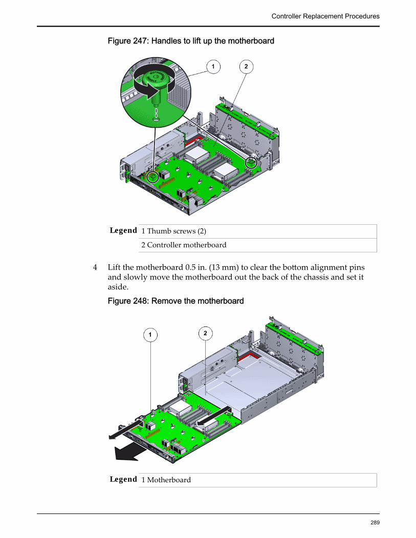
Figure 247: Handles to lift up the motherboard
Legend 1 Thumb screws (2)
2 Controller motherboard
4 Lift the motherboard 0.5 in. (13 mm) to clear the bottom alignment pinsand slowly move the motherboard out the back of the chassis and set itaside.
Figure 248: Remove the motherboard
Legend 1 Motherboard
Controller Replacement Procedures
289

2 Controller chassis
5 Place the motherboard on an antistatic mat holding the motherboardhandles or thumb screws.
Remove a DIMM
1 Remove the DIMMs by pressing down on the tabs on both sides of theDIMM to unlock it from the slot.
Figure 249: Remove DIMMs
Legend 1 Tabs to release DIMMs
2 DIMM
3 DIMM slot
Note: Pressing on the fault remind button on the motherboard lights up thefault LED. The fault remind button helps to identify the faulted DIMMs.However, press the fault remind button only when necessary, because thecapacitor powering up the fault remind button can be sustained only for 60seconds.
Note: While inserting or removing DIMMs, ensure that there is nointerference with the cables. Pulling or pressing down on the cables mightcause damage to the cables during the replacement procedure.
2 Lift out the DIMM and set aside on an antistatic mat.
Note: Visually inspect the slots and the memory for physical damage bychecking for cracked or broken plastic in the slot.
Note: Sometimes memory might fault because of dust or improperalignment or damaged slots. Use only compressed air to dust the memory.
Controller Replacement Procedures
290

Remove an NV-DIMM
1 Remove the NV-DIMMs by pressing down on the tabs on both sides of theNV-DIMM to unlock it from the slot.
Figure 250: Remove an NV-DIMM
Legend 1 Tabs to release NV-DIMM
2 NV-DIMM
3 NV-DIMM slot
Note: While inserting or removing NV-DIMMs, ensure that there is nointerference with the cables. Pulling or pressing down on the cables mightcause damage to the cables during the replacement procedure.
Note: Pressing the fault remind button on the motherboard lights up thefault LEDs of the NV-DIMMs even if the power cords are dis-connected.The fault remind button helps to identify the faulted LEDs.
2 Lift out the NV-DIMM from the slot and set aside on an antistatic mat.
Note: Visually inspect the DIMM slots, NV-DIMM slots, the DIMM, andthe NV-DIMM for physical damage by checking for cracked or brokenplastic in the slot.
Note: Sometimes DIMMs and NV-DIMMs might fault because of dust orimproper alignment or damaged slots. Use only compressed air to dustDIMMs or NV-DIMMs.
Remove a Heat Sink
Controller Replacement Procedures
291
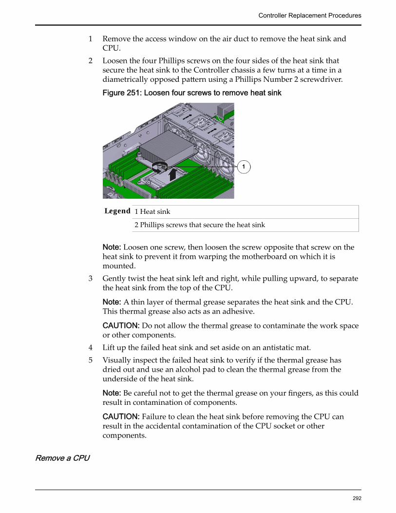
1 Remove the access window on the air duct to remove the heat sink andCPU.
2 Loosen the four Phillips screws on the four sides of the heat sink thatsecure the heat sink to the Controller chassis a few turns at a time in adiametrically opposed pattern using a Phillips Number 2 screwdriver.
Figure 251: Loosen four screws to remove heat sink
Legend 1 Heat sink
2 Phillips screws that secure the heat sink
Note: Loosen one screw, then loosen the screw opposite that screw on theheat sink to prevent it from warping the motherboard on which it ismounted.
3 Gently twist the heat sink left and right, while pulling upward, to separatethe heat sink from the top of the CPU.
Note: A thin layer of thermal grease separates the heat sink and the CPU.This thermal grease also acts as an adhesive.
CAUTION: Do not allow the thermal grease to contaminate the work spaceor other components.
4 Lift up the failed heat sink and set aside on an antistatic mat.5 Visually inspect the failed heat sink to verify if the thermal grease has
dried out and use an alcohol pad to clean the thermal grease from theunderside of the heat sink.
Note: Be careful not to get the thermal grease on your fingers, as this couldresult in contamination of components.
CAUTION: Failure to clean the heat sink before removing the CPU canresult in the accidental contamination of the CPU socket or othercomponents.
Remove a CPU
Controller Replacement Procedures
292

1 Disengage the CPU release lever on the right side of the CPU socket(viewing the Controller from the front) by pushing down and moving it tothe side away from the CPU, and then rotating the lever upward.
Figure 252: Disengage CPU release lever
Legend 1 CPU release lever
2 CPU
3 CPU socket
Note: This exposes the CPU inside the CPU socket.
2 Disengage the CPU socket release lever on the left side of the CPU socket(viewing the Controller from the front) by pushing down and moving it tothe side away from the CPU, and then rotating the lever upward.
Figure 253: Disengage CPU socket release lever
Legend 1 CPU socket release lever
2 CPU
3 CPU pressure frame
3 Swing the CPU pressure frame to fully open position and gently disengagethe CPU pins on the underside to lift up the CPU from the CPU socket.
Controller Replacement Procedures
293
CAUTION: Handle the CPU socket pins with extreme care. CPU socketpins are very fragile. A light touch can bend the CPU socket pins anddamage the board beyond repair.
4 Use the syringe to apply approximately 0.1 ml of thermal grease to the topcenter of the CPU.
CAUTION: Whenever you remove a CPU, you must replace it with anotherCPU and reinstall the heat sink. Otherwise, the Controller might overheatdue to improper airflow.
5 Set aside the failed CPU on an antistatic mat.
About Controller Motherboard Cables
The motherboard cables provide power, switch, or signal connectivity to thevarious Controller components. Damage to any of these cables might impact thenormal operations of the Controller and must be replaced as soon as possible.
Each Controller has five cable bundles that are routed throughout the chassis.The motherboard cables bundles are field replaceable units (FRUs). Replacingmotherboard cables requires you to bring the Controller offline. The five cablebundles included in the motherboard cable kit are as follows:
• SAS cable: Cables connected to the Controller backplane and a SASconnector on the motherboard.
• CUID cable: Cables that connect the Controller identification display(CUID) to the motherboard and supplies power and signal to the CUID.
• LED board cable: Cables that connect the LED alarm assembly to themotherboard and supplies power and switch connectivity to the LEDalarm assembly.
• Drive signal cable: Cables that connect the motherboard and the drive cageand supplies power to the hard drives in the drive cage.
• PDB signal cable: A flat cable that connects the power distribution board(PDB) to the motherboard and provides signal connectivity to the PDB.
The following figure identifies all the internal cables on the Controllermotherboard.
Controller Replacement Procedures
294
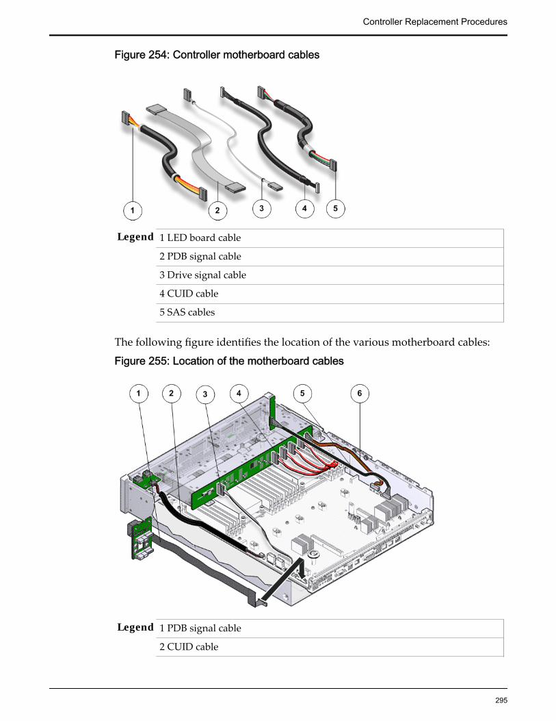
Figure 254: Controller motherboard cables
Legend 1 LED board cable
2 PDB signal cable
3 Drive signal cable
4 CUID cable
5 SAS cables
The following figure identifies the location of the various motherboard cables:
Figure 255: Location of the motherboard cables
Legend 1 PDB signal cable
2 CUID cable
Controller Replacement Procedures
295
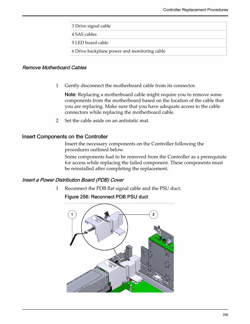
3 Drive signal cable
4 SAS cables
5 LED board cable
6 Drive backplane power and monitoring cable
Remove Motherboard Cables
1 Gently disconnect the motherboard cable from its connector.
Note: Replacing a motherboard cable might require you to remove somecomponents from the motherboard based on the location of the cable thatyou are replacing. Make sure that you have adequate access to the cableconnectors while replacing the motherboard cable.
2 Set the cable aside on an antistatic mat.
Insert Components on the ControllerInsert the necessary components on the Controller following theprocedures outlined below.Some components had to be removed from the Controller as a prerequisitefor access while replacing the failed component. These components mustbe reinstalled after completing the replacement.
Insert a Power Distribution Board (PDB) Cover1 Reconnect the PDB flat signal cable and the PSU duct.
Figure 256: Reconnect PDB PSU duct
Controller Replacement Procedures
296
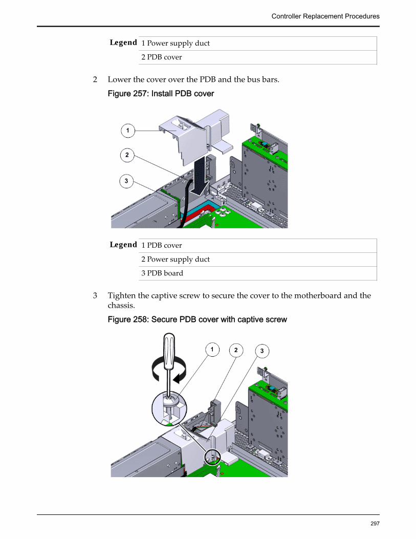
Legend 1 Power supply duct
2 PDB cover
2 Lower the cover over the PDB and the bus bars.
Figure 257: Install PDB cover
Legend 1 PDB cover
2 Power supply duct
3 PDB board
3 Tighten the captive screw to secure the cover to the motherboard and thechassis.
Figure 258: Secure PDB cover with captive screw
Controller Replacement Procedures
297

Legend 1 PDB captive screw
2 Power supply duct
3 PDB cover
Insert Motherboard Cables
Gently reconnect the motherboard cable to its connectors at both ends.
Insert an NVDIMM
Press the NV-DIMM fully into the NV-DIMM slot and ensure that the tabson both sides of the NV-DIMM are locked.
Important: Ensure that the notch in the NV-DIMM lines up with the key inthe slot.
Note: Replace only one NV-DIMM at a time to make sure that they areinserted into the correct slots. Attempting to insert multiple NV-DIMMsinto the slots might damage the NV-DIMMs due to excessive flexure.
Note: Never leave a DIMM or an NV-DIMM slot unpopulated. Insert fillersinto empty DIMM or NV-DIMM slots to ensure proper air flow inside theController.
Note: NV-DIMM slot numbering is different from ESM slot numbering.Refer to the NV-DIMM-to-ESM cabling map on the service label of theESM drive cage for more information.
Insert a DIMM
Press the DIMM fully into the DIMM slot and ensure that the tabs on bothsides of the DIMM are locked.
Controller Replacement Procedures
298
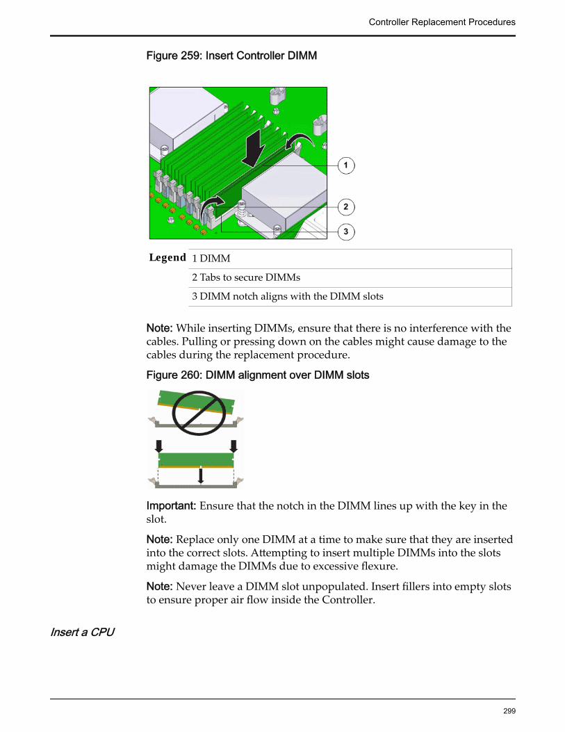
Figure 259: Insert Controller DIMM
Legend 1 DIMM
2 Tabs to secure DIMMs
3 DIMM notch aligns with the DIMM slots
Note: While inserting DIMMs, ensure that there is no interference with thecables. Pulling or pressing down on the cables might cause damage to thecables during the replacement procedure.
Figure 260: DIMM alignment over DIMM slots
Important: Ensure that the notch in the DIMM lines up with the key in theslot.
Note: Replace only one DIMM at a time to make sure that they are insertedinto the correct slots. Attempting to insert multiple DIMMs into the slotsmight damage the DIMMs due to excessive flexure.
Note: Never leave a DIMM slot unpopulated. Insert fillers into empty slotsto ensure proper air flow inside the Controller.
Insert a CPU
Controller Replacement Procedures
299

1 Gently align the underside of the CPU to the pins on the CPU socket andpush down to secure the CPU in the socket.
CAUTION: Handle the CPU socket pins with extreme care. CPU socketpins are very fragile. A light touch can bend the CPU socket pins anddamage the board beyond repair.
2 Swing the CPU pressure frame to its fully closed position.
Figure 261: Close CPU pressure frame
Legend 1 CPU release lever
2 CPU
3 CPU pressure frame
3 Push down on the two socket release levers of the CPU socket to secure theCPU inside.
Insert a Heat Sink
1 Secure the heat sink over the CPU to the Controller motherboard byinserting the four screws on the four sides of the heat sink.
Note: Ensure that the CPU is cleaned with an alcohol pad and freshthermal grease is applied, when installing a new heat sink, to preventoverheating and damage to the CPU.
Important: Ensure that the heat sink and the screws are aligned correctlyand the screws on diagonal ends of the heat sink are tightened first. Aslight force might need to be applied to push down the screwdriver whiletightening the screws to overcome the tension generated.
2 Tighten the four Phillips screws on the heat sink a few turns at a time in adiametrically opposed pattern using a Phillips Number 2 screwdriver.
Controller Replacement Procedures
300

Figure 262: Insert heat sink
Legend 1 Heat sink
2 Phillips screws that secure the heat sink
Insert a Riser
1 Lower the riser onto the Controller motherboard and press the riser edgeconnector securely into the socket.
Important: Ensure that any HBAs that must be removed from the failedriser and placed onto the replacement rise are inserted into the same slotson the replacement riser.
Figure 263: Insert riser
Legend 1 Riser
Controller Replacement Procedures
301
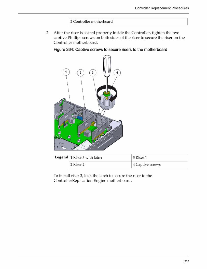
2 Controller motherboard
2 After the riser is seated properly inside the Controller, tighten the twocaptive Phillips screws on both sides of the riser to secure the riser on theController motherboard.
Figure 264: Captive screws to secure risers to the motherboard
Legend 1 Riser 3 with latch 3 Riser 1
2 Riser 2 4 Captive screws
To install riser 3, lock the latch to secure the riser to theControllerReplication Engine motherboard.
Controller Replacement Procedures
302

Figure 265: Riser 3 latch locked
Legend 1 Riser 3 latch 3 HBA
2 Riser 3
3 Reconnect any previously removed internal or external cables to any HBAsinstalled in the riser.
4 Repeat the above steps for any additional risers that you are installing.
Insert a Motherboard
1 Unpack the component from its shipping carton.
Note: Place the component on an antistatic mat if it must be set aside forany reason.
2 Use the two thumb screws or handles to place the motherboard onto theController chassis gently.
Note: Due to the tight fit inside the Controller chassis, care must be takenwhile inserting the motherboard into the chassis. Do not flex the PDBboard and ensure that the screw holes on the chassis align correctly withthe motherboard while inserting the motherboard into the Controllerchassis.
3 Lift the motherboard gently by the handles to a height of about 0.5 in. (13mm) and slowly move the motherboard forward into the chassis from therear.
Controller Replacement Procedures
303

4 When there is about 1.5 inches (36 millimeters) to go, lower themotherboard onto the bottom alignment pins.
5 Slowly slide the motherboard forward until it drops, engaging the bottomalignment pins.
6 Continue to slide the motherboard forward until it seats.
Note: The back of the motherboard must be flush with the back of thechassis. Additionally, the four holes in the motherboard must align withthe four holes in the bus bars.
7 Tighten the captive screws, the four bus bar screws, and reconnect thecables that you previously disconnected.
Figure 266: Secure the motherboard
Legend 1 PDB cable bundle
2 Motherboard cables
3 Bus bar screws that secure the PDB to motherboard
4 Thumb screws or handles to remove and insert the motherboard tothe chassis
5 Controller motherboard
Lower the Drive Compartment1 Rotate the drive compartment and backplane back into position inside the
Controller and ensure that the alignment pins engage.
Note: To confirm that the backplane is locked into position, listen for anaudible click or feel the backplane engage with the Controller.
Controller Replacement Procedures
304
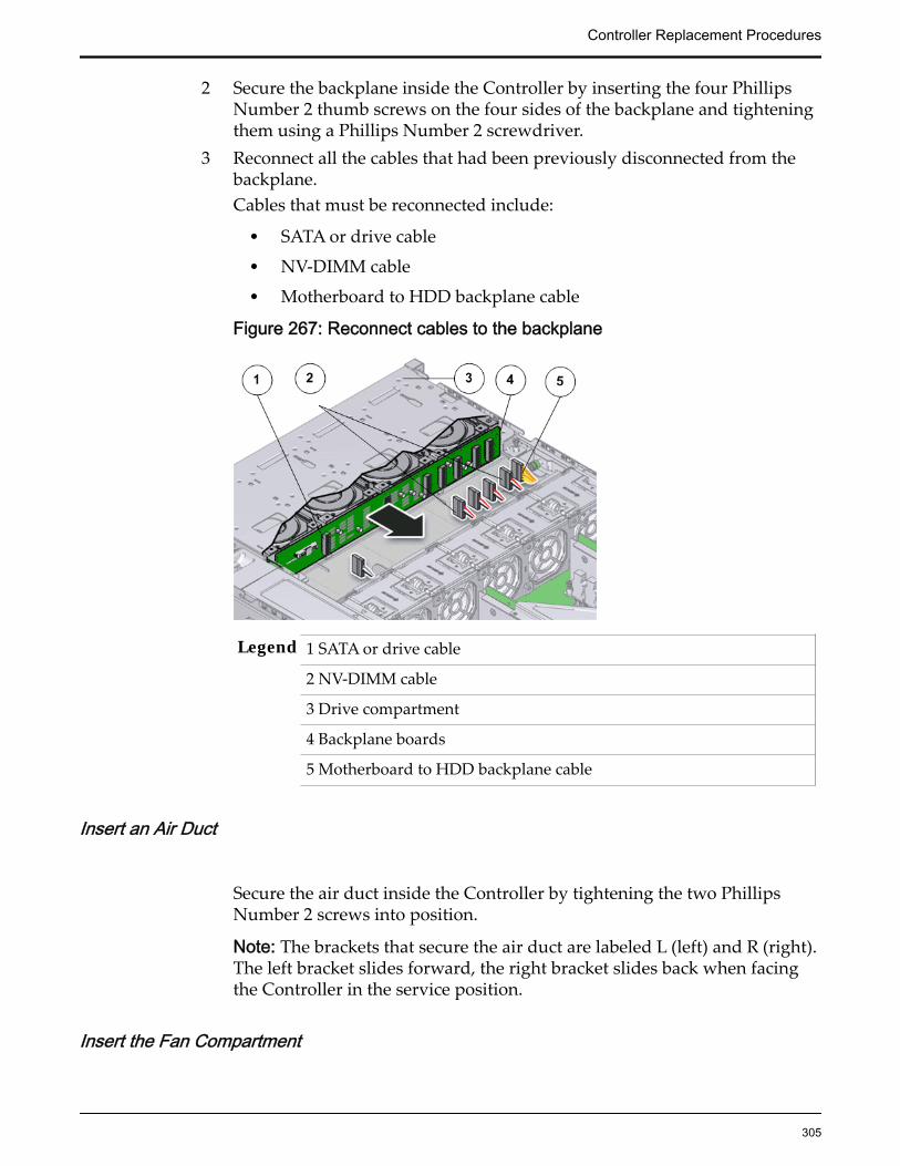
2 Secure the backplane inside the Controller by inserting the four PhillipsNumber 2 thumb screws on the four sides of the backplane and tighteningthem using a Phillips Number 2 screwdriver.
3 Reconnect all the cables that had been previously disconnected from thebackplane.Cables that must be reconnected include:
• SATA or drive cable
• NV-DIMM cable
• Motherboard to HDD backplane cable
Figure 267: Reconnect cables to the backplane
Legend 1 SATA or drive cable
2 NV-DIMM cable
3 Drive compartment
4 Backplane boards
5 Motherboard to HDD backplane cable
Insert an Air Duct
Secure the air duct inside the Controller by tightening the two PhillipsNumber 2 screws into position.
Note: The brackets that secure the air duct are labeled L (left) and R (right).The left bracket slides forward, the right bracket slides back when facingthe Controller in the service position.
Insert the Fan Compartment
Controller Replacement Procedures
305

1 Move any loose cables so that they are against the Controller chassis walls.
2 Align the fan compartment to where it installs into the Controller chassis.
Figure 268: Insert the fan compartment
Legend 1 Fan compartment
2 Controller chassis
Note: The single arrow on the right end of the fan compartment aligns withthe single arrow on the power supply bay.
3 Slowly lower the fan compartment into the Controller chassis, gentlyworking the cables into the gaps between the fan compartment and thechassis walls.
4 Verify that the fan compartment is properly seated, no cables are pinched,and the top surfaces of the fan compartment are flush with theControllerReplication Engine chassis.
Insert a Fan Module
Insert the replacement fan module into the Controller.
Controller Replacement Procedures
306

Figure 269: Insert fan module
Legend 1 Controller chassis
2 Fan compartment
3 Fan module
Note: Press down on the fan module and apply firm pressure to fully seatthe fan module into the fan compartment. The fan modules are notched toensure that they are installed in the correct orientation.
Note: Repeat for each additional fan module.
Insert an Air Filter1 Tilt the top of the air filter slightly towards you and insert the bottom two
hooks into the mounting tabs.
Controller Replacement Procedures
307
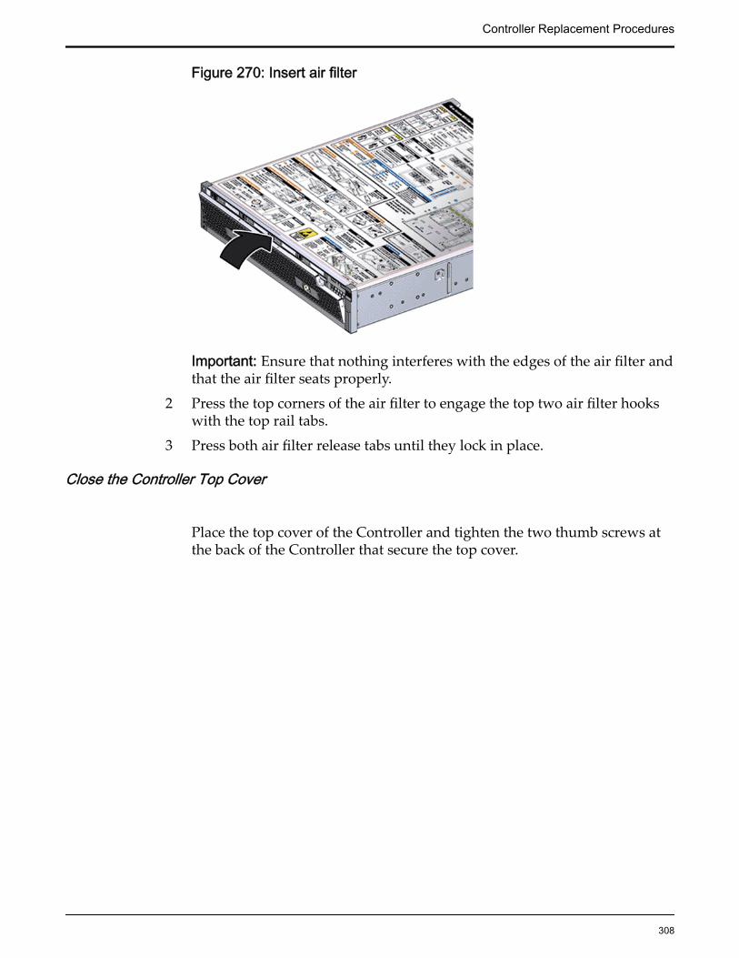
Figure 270: Insert air filter
Important: Ensure that nothing interferes with the edges of the air filter andthat the air filter seats properly.
2 Press the top corners of the air filter to engage the top two air filter hookswith the top rail tabs.
3 Press both air filter release tabs until they lock in place.
Close the Controller Top Cover
Place the top cover of the Controller and tighten the two thumb screws atthe back of the Controller that secure the top cover.
Controller Replacement Procedures
308

Figure 271: Close Controller top cover
Legend 1 Thumb screws
2 Controller top cover
3 Controller
Reconnect Controller Cabling
1 Reconnect all the data cables on the Controller.
Note: Oracle Customer Support recommends labeling all cables connectedto the Controller so that the cables can be reconnected accurately to theController after the replacement procedure is complete.
2 Reconnect the CMA to the Controller by attaching the release tab on theleft and right side of the CMA.
Slide Controller to Rack Position
Slide the Controller back into the rack.
Note: You must release the rail locking mechanism to slide the Controllerchassis back into the rack.
Controller Replacement Procedures
309

Power On the ControllerPower on the Controller using the power button and the ILOM webinterface.
Note: As soon as the power cords are connected to the Controller, standbypower is applied. In standby power mode, the Power/OK LED on theController front panel blinks every five seconds or so. However, to applymain power to the Controller, you must use the power button and the webinterface. When main power is applied to the Controller, the green Power/OK LED on the front panel of the Controller blinks steadily. When theController BIOS has completed booting, the OK LED remains lit.
Verify Controller Component Status
1 From Guided Maintenance, verify that the status is Normal.
You can also verify the status by navigating to System > Hardware andthen selecting a chassis. The Overview page for the selected chassis lists thestatus of each component.
Note: The Controller status will be visible several minutes after beingpowered on.
2 Review the status of the LEDs to confirm a status of Normal.
Update the Controller BIOSUpdate the Controller BIOS to ensure that the latest version of the BIOS isinstalled on the Controller.
Following are the prerequisites to update the Controller BIOS:
• A laptop or desktop with network access to the Oracle FS System
• A PuTTY or an alternative application on the laptop
• The login credentials for the Pilot root password
• The scroll-back properties of the shell window set to 100,000 lines.
• A Controller with a replaced motherboard that is powered on and has allpower cables securely connected.
Controller BIOS updates are required when a new version of the BIOS is releasedor when a Controller motherboard is replaced. Perform the Controller BIOSupdate after the Controller motherboard has been replaced. Usually, theController BIOS is automatically updated to the latest version. However, if amanual update is required, please follow these instructions.
1 Open a PuTTY session using the shared IP address for the Oracle FSSystem.
2 Login to the Pilot.
Required credentials:
Controller Replacement Procedures
310

• Username: root• Password: a1s2d3f$
3 Use the cat command to confirm that the Controller with the replacementmotherboard can be brought online.[root@pilot2 ~]# cat /etc/nodenamesNote: Make a note of the IP address and the world-wide name (WWN) ofthe Controller that does not have the replacement motherboard. Also, notethe IP address of the Pilot.
The following list provides information on the IP address and the WWN ofthe Controller and the IP address of the Pilot:
• 172.30.80.3 WN2009fffffffffffa WN2008000101000000mgmtnode
• 172.30.80.2 WN2008fffffffffff2• 172.30.80.129 WN508002000158ba01 WN2008000101000001
Note: The Pilot IP address concludes with “mgmtnode” in the output.
Note: The Controller with the replaced motherboard has not fully startedyet and therefore, is not available on the private management interface(PMI) network.
4 From the Pilot, log in to the IP address of the Controller that did not haveits motherboard replaced using secure shell (SSH).[root@pilot2 ~]# ssh 172.30.80.129
5 Ensure access from the current active Controller to the inactive Controller,on which the motherboard was replaced, by pinging the ILOM interface.WN508002000158BA01 # ping 169.254.2.9If there is no ping response, verify that all the Controller cables areaccurately connected. The ping response is as follows:
• PING 169.254.2.9 (169.254.2.9): 56 data bytes• 64 bytes from 169.254.2.9: seq=0 ttl=64 time=0.665 ms• 64 bytes from 169.254.2.9: seq=1 ttl=64 time=0.519 ms• 64 bytes from 169.254.2.9: seq=2 ttl=64 time=0.653 ms
6 Copy the Controller BIOS file from the Pilot to the Controller.a) Navigate to the /var/tftp/ directory on the Controller.
WN508002000158BA01 # cd /var/tftp/b) Validate the current directory to ensure the existence of the /var/
tftp/ directory.WN508002000158BA01 # pwd
c) Validate that the spbios.rom file was copied to the /var/tftp/directory on the Controller
Controller Replacement Procedures
311

WN508002000158BA01 # lsspbios.rom
d) Validate the files that were copied to the /var/tftp/ directory of theController.WN508002000158BA01 # lsfs_bios_settings.xml spbios.rom
7 Log in to the ILOM port of the Controller on which the motherboard wasreplaced using SSH.
8 Enter the ILOM password when prompted, after the connection to theILOM port of the Controller is established.ssh 169.254.2.9Required credentials:
• Username (if required): root• Password: changeme
Note: The ILOM information of the alternate Controller will also beavailable on the PuTTY screen.
9 Verify that the active Controller is the Controller on which themotherboard was replaced.-> show /SYSThis displays the system serial number (SSN), which must be confirmed bylooking at the number on the back of the Controller.
10 After confirming that the SSN is the same as that displayed at the back ofthe Controller, power down the Controller.-> stop /SystemNote: Click on y and then ENTER to confirm that the Oracle FS System hasstopped.
11 Obtain and load the Controller BIOS file from the Controller that did nothave a motherboard replaced.
12 Compare the Controller BIOS firmware file with the existing firmware filethat is currently installed on the Controller and upgrade the BIOS firmwarefile, if necessary.-> load -source tftp://169.254.2.10/spbios.romNote: When using the TFTP protocol, you do not need to specify thecomplete path to the *.rom file located on the Controller.
A display screen appears with question prompts on ILOM upgrade.13 Answer y to all the questions on the display screen.
Are you sure you want to load the specified file (y/n)?yPreserve existing SP configuration (y/n)?yPreserve existing BIOS configuration (y/n)?yDelay BIOS upgrade until next server power off (y/n)?y
Controller Replacement Procedures
312

The Controller BIOS file is upgraded and the Controller is automaticallystarted and power cycled.
14 Log in to the ILOM port of the Controller on which the motherboard wasreplaced and stop the Oracle FS System.-> stop /SystemNote: The session ends when the Controller reboots to activate the newBIOS.
15 Specify the Controller BIOS changes that are mandatory at the ILOMprompt so that the Controller can start.
a) Enable the “Auto Power ON” setting.-> set /SP/policy/ HOST_AUTO_POWER_ON=enabledSet 'HOST_AUTO_POWER_ON' to 'enabled'
b) Confirm that the “HOST_AUTO_POWER_ON” setting is on.-> show /SP/policy/
c) Enable the “Expert Mode” setting.-> set /System/BIOS/Config/ expert_mode=enabledSet 'expert_mode' to 'enabled'
16 Obtain and set the Controller XML file from the Controller on which themotherboard was not replaced.-> set /System/BIOS/Config/ load_uri=tftp://169.254.2.10/fs_bios_settings.xmlNote: When using the TFTP protocol, you do not need to specify thecomplete path to the *.rom file located on the Controller.
Load successful17 Start the Controller and exit out from the ILOM, Controller, and the Pilot
connection.-> start /System
Replace Controller Motherboard CablesThe motherboard cables provide power, switch, or signal connectivity to thevarious Controller components. Damage to any of these cables might impact thenormal operations of the Controller and must be replaced as soon as possible.
Prerequisites: • Ensure that you have a Phillips Number 2screwdriver with at least a four-inch shaft.
• Before handling a component, touch a groundedsurface to discharge any static electricity.
Controller Replacement Procedures
313
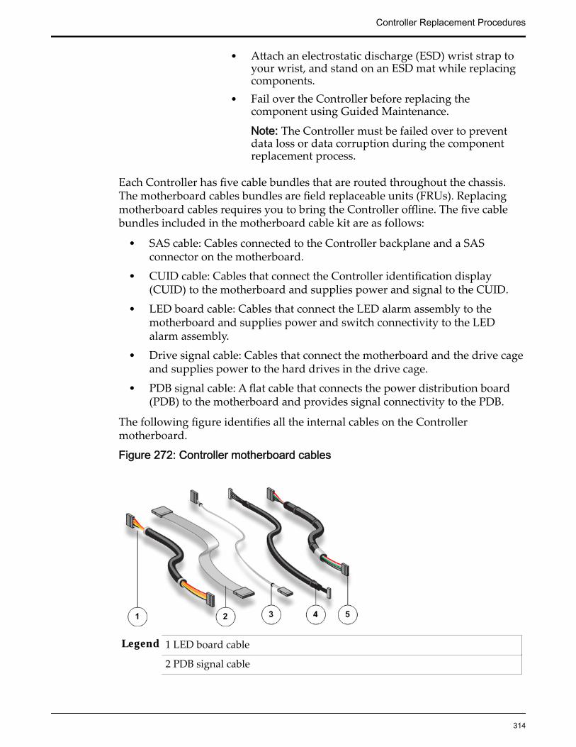
• Attach an electrostatic discharge (ESD) wrist strap toyour wrist, and stand on an ESD mat while replacingcomponents.
• Fail over the Controller before replacing thecomponent using Guided Maintenance.
Note: The Controller must be failed over to preventdata loss or data corruption during the componentreplacement process.
Each Controller has five cable bundles that are routed throughout the chassis.The motherboard cables bundles are field replaceable units (FRUs). Replacingmotherboard cables requires you to bring the Controller offline. The five cablebundles included in the motherboard cable kit are as follows:
• SAS cable: Cables connected to the Controller backplane and a SASconnector on the motherboard.
• CUID cable: Cables that connect the Controller identification display(CUID) to the motherboard and supplies power and signal to the CUID.
• LED board cable: Cables that connect the LED alarm assembly to themotherboard and supplies power and switch connectivity to the LEDalarm assembly.
• Drive signal cable: Cables that connect the motherboard and the drive cageand supplies power to the hard drives in the drive cage.
• PDB signal cable: A flat cable that connects the power distribution board(PDB) to the motherboard and provides signal connectivity to the PDB.
The following figure identifies all the internal cables on the Controllermotherboard.
Figure 272: Controller motherboard cables
Legend 1 LED board cable
2 PDB signal cable
Controller Replacement Procedures
314
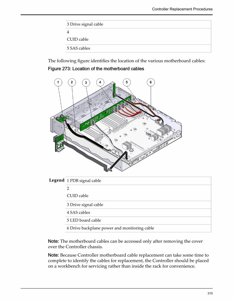
3 Drive signal cable
4
CUID cable
5 SAS cables
The following figure identifies the location of the various motherboard cables:
Figure 273: Location of the motherboard cables
Legend 1 PDB signal cable
2
CUID cable
3 Drive signal cable
4 SAS cables
5 LED board cable
6 Drive backplane power and monitoring cable
Note: The motherboard cables can be accessed only after removing the coverover the Controller chassis.
Note: Because Controller motherboard cable replacement can take some time tocomplete to identify the cables for replacement, the Controller should be placedon a workbench for servicing rather than inside the rack for convenience.
Controller Replacement Procedures
315

CAUTION: Replacement of the Controller motherboard cables requires assistancefrom Oracle Customer Support.
CAUTION: Ensure that all power is removed from the Controller beforeremoving or installing the motherboard. Disconnect the power cords beforeperforming the motherboard replacement procedure.
Procedure Overview
1 Prepare the Component for Replacement
2 Remove the Controller Power Supply Cords
3 Disconnect Controller Cabling
4 Slide Controller to Service Position
5 (Optional) Remove Controller Chassis From Rack
6 Remove Components From the Controller
7 Remove Motherboard Cables
8 Insert Motherboard Cables
9 Insert Components on the Controller
10 Insert the Controller Onto the Rack
Related LinksController Components
Prepare the Component for Replacement
1 From Oracle FS System Manager (GUI), navigate to Support > SystemTrouble.
2 Select the Controller that contains the component that is to be replaced.
3 Select Actions > Replace Component.Guided Maintenance displays the list of replaceable components for theController.
Note: Field replaceable units (FRUs) can only be replaced by fieldtechnicians with support role privileges.
4 Select a component from the list.
5 Click Next.
Guided Maintenance displays the Identify Hardware dialog.
6 From the Identify Hardware dialog, specify how you want to identify thechassis so that you can locate it in the data center.
You can select one of the following methods to identify the chassis:
Identify Flashes the LEDs on the chassis that contains the failedcomponent.
Controller Replacement Procedures
316
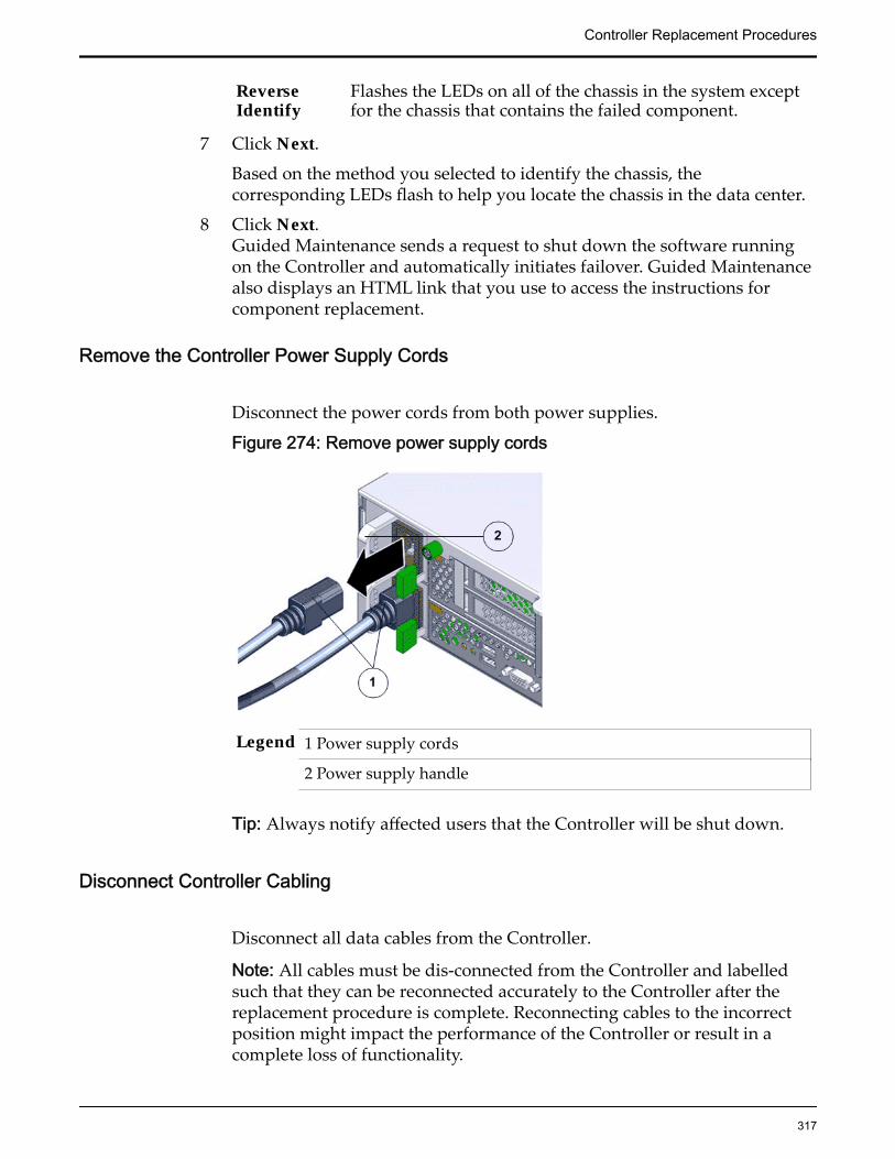
ReverseIdentify
Flashes the LEDs on all of the chassis in the system exceptfor the chassis that contains the failed component.
7 Click Next.
Based on the method you selected to identify the chassis, thecorresponding LEDs flash to help you locate the chassis in the data center.
8 Click Next.Guided Maintenance sends a request to shut down the software runningon the Controller and automatically initiates failover. Guided Maintenancealso displays an HTML link that you use to access the instructions forcomponent replacement.
Remove the Controller Power Supply Cords
Disconnect the power cords from both power supplies.
Figure 274: Remove power supply cords
Legend 1 Power supply cords
2 Power supply handle
Tip: Always notify affected users that the Controller will be shut down.
Disconnect Controller Cabling
Disconnect all data cables from the Controller.
Note: All cables must be dis-connected from the Controller and labelledsuch that they can be reconnected accurately to the Controller after thereplacement procedure is complete. Reconnecting cables to the incorrectposition might impact the performance of the Controller or result in acomplete loss of functionality.
Controller Replacement Procedures
317
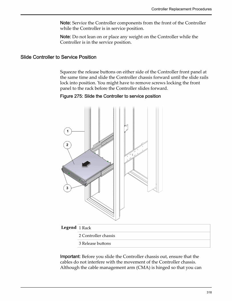
Note: Service the Controller components from the front of the Controllerwhile the Controller is in service position.
Note: Do not lean on or place any weight on the Controller while theController is in the service position.
Slide Controller to Service Position
Squeeze the release buttons on either side of the Controller front panel atthe same time and slide the Controller chassis forward until the slide railslock into position. You might have to remove screws locking the frontpanel to the rack before the Controller slides forward.
Figure 275: Slide the Controller to service position
Legend 1 Rack
2 Controller chassis
3 Release buttons
Important: Before you slide the Controller chassis out, ensure that thecables do not interfere with the movement of the Controller chassis.Although the cable management arm (CMA) is hinged so that you can
Controller Replacement Procedures
318
extend the Controller chassis, all cables and cords must be out of the waywhen you service the Controller components.
CAUTION: Deploy any rack anti-tilt mechanism before releasing therelease buttons and extending the Controller chassis.
(Optional) Remove Controller Chassis From Rack
1 From the front of the Controller, press on the slide-rail release tabs on bothsides at the front of the Controller, and pull the Controller out of the rackuntil is free of the rack rails.
Important: Oracle recommends not removing the Controller from the railsfor servicing the components. All components are designed forreplacement and servicing while the Controller chassis is on the rails.However, if you must remove the Controller from the rack, disconnect therear panel Controller cables from the front with the Controller in serviceposition.
Note: A slide-rail release tab is located on each slide-rail of the Controller.
2 With the help of a partner or a mechanical lift, place the Controller on anantistatic surface on a workbench.
Remove Components From the Controller
Note: Some components must be removed from the Controller as a prerequisitefor access while replacing the failed component.
Note: All components that are removed from the Controller must be placed on anantistatic surface or ESD qualified mat.
Open the Controller Top Cover
1 Fully loosen the two captive thumb screws at the back of the top coverusing the Phillips number 2 screwdriver, if necessary.
Controller Replacement Procedures
319

Figure 276: Captive thumb screws to remove the top cover
Legend 1 Controller top cover
2 Captive screws
2 Slide the top cover backwards 0.5 inches (13 mm) and lift the top coverstraight up and off the Controller chassis.
Remove a Fan Module
1 Using your thumb and forefinger, grasp the removal tab and gently lift thefan module from the fan compartment.
Controller Replacement Procedures
320

Figure 277: Remove fan module
Legend 1 Controller chassis
2 Fan compartment
3 Removal tab
4 Fan module
Note: Pulling the green tab from the middle releases the locking tab foreach individual fan.
Note: When removing a fan module, do not rock it back and forth. Rockingthe fan module can cause damage to the motherboard connectors.
2 Set the fan module aside.
Note: The fan compartment might come out when the last fan module isremoved.
Remove the Fan Compartment
1 Lift the fan compartment straight up and out of the Controller chassis.
Controller Replacement Procedures
321

Figure 278: Remove fan compartment
Legend 1 ControllerReplication Engine chassis
2 Fan compartment
Note: All fan modules must be removed from the fan compartment beforeremoving the fan compartment.
2 Set the component aside.
Remove Motherboard Cables
1 Gently disconnect the motherboard cable from its connector.
Note: Replacing a motherboard cable might require you to remove somecomponents from the motherboard based on the location of the cable thatyou are replacing. Make sure that you have adequate access to the cableconnectors while replacing the motherboard cable.
2 Set the cable aside on an antistatic mat.
Insert Motherboard Cables
Gently reconnect the motherboard cable to its connectors at both ends.
Controller Replacement Procedures
322
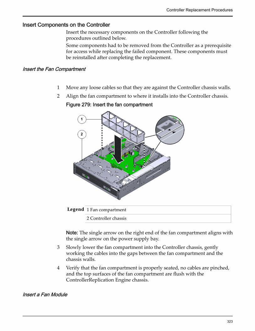
Insert Components on the ControllerInsert the necessary components on the Controller following theprocedures outlined below.Some components had to be removed from the Controller as a prerequisitefor access while replacing the failed component. These components mustbe reinstalled after completing the replacement.
Insert the Fan Compartment
1 Move any loose cables so that they are against the Controller chassis walls.
2 Align the fan compartment to where it installs into the Controller chassis.
Figure 279: Insert the fan compartment
Legend 1 Fan compartment
2 Controller chassis
Note: The single arrow on the right end of the fan compartment aligns withthe single arrow on the power supply bay.
3 Slowly lower the fan compartment into the Controller chassis, gentlyworking the cables into the gaps between the fan compartment and thechassis walls.
4 Verify that the fan compartment is properly seated, no cables are pinched,and the top surfaces of the fan compartment are flush with theControllerReplication Engine chassis.
Insert a Fan Module
Controller Replacement Procedures
323
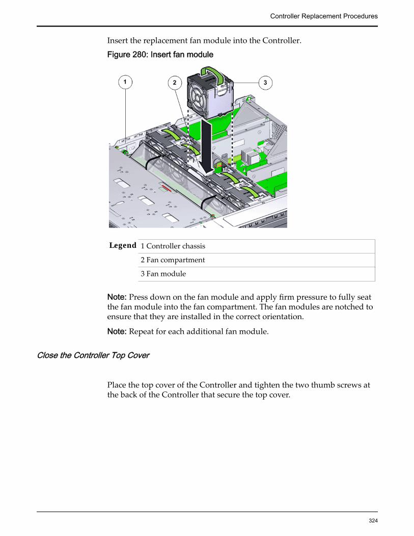
Insert the replacement fan module into the Controller.
Figure 280: Insert fan module
Legend 1 Controller chassis
2 Fan compartment
3 Fan module
Note: Press down on the fan module and apply firm pressure to fully seatthe fan module into the fan compartment. The fan modules are notched toensure that they are installed in the correct orientation.
Note: Repeat for each additional fan module.
Close the Controller Top Cover
Place the top cover of the Controller and tighten the two thumb screws atthe back of the Controller that secure the top cover.
Controller Replacement Procedures
324
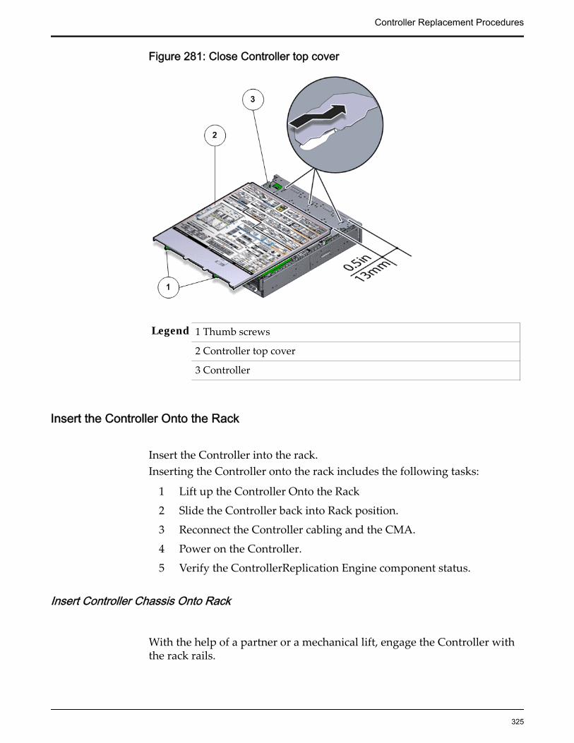
Figure 281: Close Controller top cover
Legend 1 Thumb screws
2 Controller top cover
3 Controller
Insert the Controller Onto the Rack
Insert the Controller into the rack.Inserting the Controller onto the rack includes the following tasks:
1 Lift up the Controller Onto the Rack
2 Slide the Controller back into Rack position.
3 Reconnect the Controller cabling and the CMA.
4 Power on the Controller.
5 Verify the ControllerReplication Engine component status.
Insert Controller Chassis Onto Rack
With the help of a partner or a mechanical lift, engage the Controller withthe rack rails.
Controller Replacement Procedures
325

CAUTION: Do not use the power supply handles to lift the Controller.Using the power supply handles to lift the Controller can damage thepower supplies and disrupt electrical power to the
Slide Controller to Rack Position
Slide the Controller back into the rack.
Note: You must release the rail locking mechanism to slide the Controllerchassis back into the rack.
Reconnect Controller Cabling
1 Reconnect all the data cables on the Controller.
Note: Oracle Customer Support recommends labeling all cables connectedto the Controller so that the cables can be reconnected accurately to theController after the replacement procedure is complete.
2 Reconnect the CMA to the Controller by attaching the release tab on theleft and right side of the CMA.
Power On the Controller
Power on the Controller using the power button and the ILOM webinterface.
Note: As soon as the power cords are connected to the Controller, standbypower is applied. In standby power mode, the Power/OK LED on theController front panel blinks every five seconds or so. However, to applymain power to the Controller, you must use the power button and the webinterface. When main power is applied to the Controller, the green Power/OK LED on the front panel of the Controller blinks steadily. When theController BIOS has completed booting, the OK LED remains lit.
Verify Controller Component Status
1 From Guided Maintenance, verify that the status is Normal.
You can also verify the status by navigating to System > Hardware andthen selecting a chassis. The Overview page for the selected chassis lists thestatus of each component.
Controller Replacement Procedures
326
Note: The Controller status will be visible several minutes after beingpowered on.
2 Review the status of the LEDs to confirm a status of Normal.
Replace a Controller Power Distribution BoardThe power distribution board (PDB) connects the two power supplies and themotherboard and distributes power by acting like a circuit breaker. A failed PDBis a critical point of failure and can affect the normal operation of the powersupplies. Failed PDBs might bring down the Controller and must be replaced assoon as possible.
CAUTION: Ensure that all power is removed from the Controller beforeremoving or installing the PDB. Also, disconnect the power cables beforeperforming the motherboard removal procedure during PDB replacement.
Prerequisites: • Ensure that you have a Phillips Number 2screwdriver with at least a four-inch shaft.
• Before handling a component, touch a groundedsurface to discharge any static electricity.
• Attach an electrostatic discharge (ESD) wrist strap toyour wrist, and stand on an ESD mat while replacingcomponents.
• Ensure that there is a workbench available to placethe Controller chassis once it is removed from therack for servicing.
• Make sure that you have a Torx Number 10screwdriver.
Each Controller has a PDB that is located behind the power supplies, under thePDB signal cable. The PDB assembly is a field replaceable unit (FRU). Replacinga PDB is not a hot-serviceable process and requires you to power down theController. The following figure shows the PDB assembly inside the Controller.
Controller Replacement Procedures
327

Figure 282: Power Distribution Board (PDB)
Note: The PDB can be accessed only after removing the cover over the Controllerchassis.
Note: Since Controller PDB replacement can take approximately an hour tocomplete and involves removing all CRUs and FRUs, Oracle Customer Supportrecommends that the Controller be placed on a workbench for servicing ratherthan inside the rack for convenience.
Note: Replacement of the PDB requires assistance from Oracle CustomerSupport.
Procedure Overview
1 Prepare the Component for Replacement
2 Remove the Controller Power Supply Cords
3 Slide Controller to Service Position
4 Disconnect Controller Cabling
5 (Optional) Remove Controller Chassis From Rack
6 Remove Components From the Controller
7 Remove a Power Distribution Board (PDB)
8 Insert a Power Distribution Board (PDB)
9 Insert Components on the Controller
10 Insert the Controller Onto the Rack
Related LinksController Components
Controller Replacement Procedures
328

Prepare the Component for Replacement
1 From Oracle FS System Manager (GUI), navigate to Support > SystemTrouble.
2 Select the Controller that contains the component that is to be replaced.
3 Select Actions > Replace Component.Guided Maintenance displays the list of replaceable components for theController.
Note: Field replaceable units (FRUs) can only be replaced by fieldtechnicians with support role privileges.
4 Select a component from the list.
5 Click Next.
Guided Maintenance displays the Identify Hardware dialog.
6 From the Identify Hardware dialog, specify how you want to identify thechassis so that you can locate it in the data center.
You can select one of the following methods to identify the chassis:
Identify Flashes the LEDs on the chassis that contains the failedcomponent.
ReverseIdentify
Flashes the LEDs on all of the chassis in the system exceptfor the chassis that contains the failed component.
7 Click Next.
Based on the method you selected to identify the chassis, thecorresponding LEDs flash to help you locate the chassis in the data center.
8 Click Next.Guided Maintenance sends a request to shut down the software runningon the Controller and automatically initiates failover. Guided Maintenancealso displays an HTML link that you use to access the instructions forcomponent replacement.
Remove the Controller Power Supply Cords
Disconnect the power cords from both power supplies.
Controller Replacement Procedures
329

Figure 283: Remove power supply cords
Legend 1 Power supply cords
2 Power supply handle
Tip: Always notify affected users that the Controller will be shut down.
Slide Controller to Service Position
Squeeze the release buttons on either side of the Controller front panel atthe same time and slide the Controller chassis forward until the slide railslock into position. You might have to remove screws locking the frontpanel to the rack before the Controller slides forward.
Controller Replacement Procedures
330

Figure 284: Slide the Controller to service position
Legend 1 Rack
2 Controller chassis
3 Release buttons
Important: Before you slide the Controller chassis out, ensure that thecables do not interfere with the movement of the Controller chassis.Although the cable management arm (CMA) is hinged so that you canextend the Controller chassis, all cables and cords must be out of the waywhen you service the Controller components.
CAUTION: Deploy any rack anti-tilt mechanism before releasing therelease buttons and extending the Controller chassis.
Disconnect Controller Cabling
Disconnect all data cables from the Controller.
Note: All cables must be dis-connected from the Controller and labelledsuch that they can be reconnected accurately to the Controller after thereplacement procedure is complete. Reconnecting cables to the incorrect
Controller Replacement Procedures
331

position might impact the performance of the Controller or result in acomplete loss of functionality.
Note: Service the Controller components from the front of the Controllerwhile the Controller is in service position.
Note: Do not lean on or place any weight on the Controller while theController is in the service position.
(Optional) Remove Controller Chassis From Rack
1 From the front of the Controller, press on the slide-rail release tabs on bothsides at the front of the Controller, and pull the Controller out of the rackuntil is free of the rack rails.
Important: Oracle recommends not removing the Controller from the railsfor servicing the components. All components are designed forreplacement and servicing while the Controller chassis is on the rails.However, if you must remove the Controller from the rack, disconnect therear panel Controller cables from the front with the Controller in serviceposition.
Note: A slide-rail release tab is located on each slide-rail of the Controller.
2 With the help of a partner or a mechanical lift, place the Controller on anantistatic surface on a workbench.
Remove Components From the Controller
Note: Some components must be removed from the Controller as a prerequisitefor access while replacing the failed component.
Note: All components that are removed from the Controller must be placed on anantistatic surface or ESD qualified mat.
Remove a Power SupplyNote: To replace a power supply, you can access the faulted power supply fromthe back of the Controller module. To access the power supply located in thebottom slot (PS-1), the CMA clip must be disconnected to enable the powersupply to clear the support arm.
Note: Replacing the power supply does not require you to slide the Controllerinto the extended rack position and can be performed while the Controller is inthe rack position.
1 Remove the power supply by grasping the power supply handle andpushing the power supply latch to the left.
Controller Replacement Procedures
332
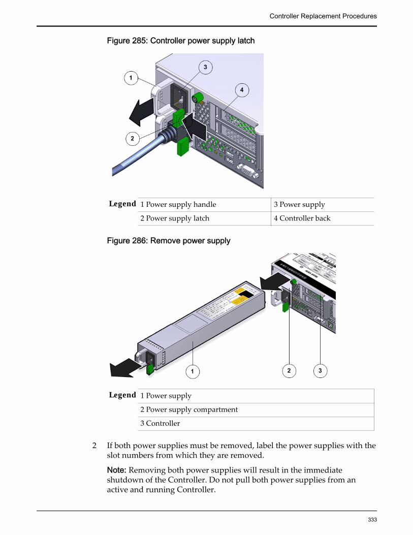
Figure 285: Controller power supply latch
Legend 1 Power supply handle 3 Power supply
2 Power supply latch 4 Controller back
Figure 286: Remove power supply
Legend 1 Power supply
2 Power supply compartment
3 Controller
2 If both power supplies must be removed, label the power supplies with theslot numbers from which they are removed.
Note: Removing both power supplies will result in the immediateshutdown of the Controller. Do not pull both power supplies from anactive and running Controller.
Controller Replacement Procedures
333
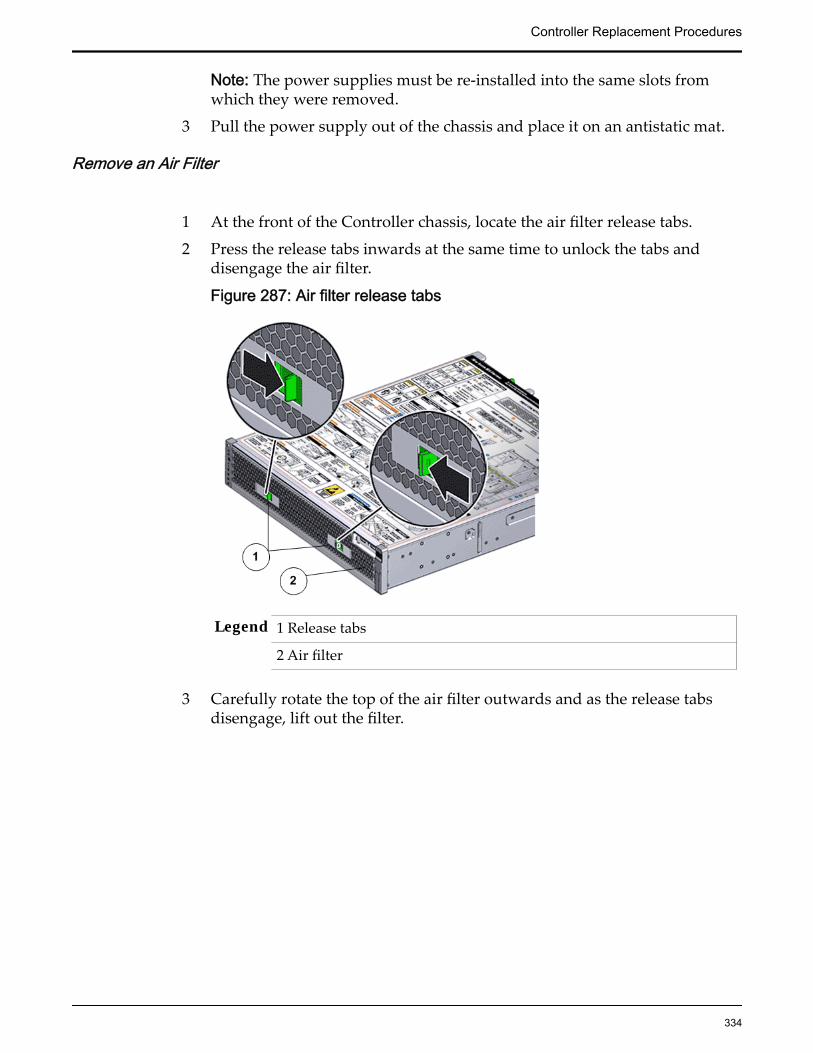
Note: The power supplies must be re-installed into the same slots fromwhich they were removed.
3 Pull the power supply out of the chassis and place it on an antistatic mat.
Remove an Air Filter
1 At the front of the Controller chassis, locate the air filter release tabs.
2 Press the release tabs inwards at the same time to unlock the tabs anddisengage the air filter.
Figure 287: Air filter release tabs
Legend 1 Release tabs
2 Air filter
3 Carefully rotate the top of the air filter outwards and as the release tabsdisengage, lift out the filter.
Controller Replacement Procedures
334

Figure 288: Remove air filter
4 Set the air filter aside.
Open the Controller Top Cover
1 Fully loosen the two captive thumb screws at the back of the top coverusing the Phillips number 2 screwdriver, if necessary.
Figure 289: Captive thumb screws to remove the top cover
Legend 1 Controller top cover
2 Captive screws
2 Slide the top cover backwards 0.5 inches (13 mm) and lift the top coverstraight up and off the Controller chassis.
Controller Replacement Procedures
335

Remove a Fan Module
1 Using your thumb and forefinger, grasp the removal tab and gently lift thefan module from the fan compartment.
Figure 290: Remove fan module
Legend 1 Controller chassis
2 Fan compartment
3 Removal tab
4 Fan module
Note: Pulling the green tab from the middle releases the locking tab foreach individual fan.
Note: When removing a fan module, do not rock it back and forth. Rockingthe fan module can cause damage to the motherboard connectors.
2 Set the fan module aside.
Note: The fan compartment might come out when the last fan module isremoved.
Remove the Fan Compartment
Controller Replacement Procedures
336

1 Lift the fan compartment straight up and out of the Controller chassis.
Figure 291: Remove fan compartment
Legend 1 ControllerReplication Engine chassis
2 Fan compartment
Note: All fan modules must be removed from the fan compartment beforeremoving the fan compartment.
2 Set the component aside.
Raise the Drive Compartment to Service Position
1 Disconnect the cables attached to the backplane.Cables that must be disconnected include:
• SATA or drive cable
• NV-DIMM cable
• Motherboard to HDD backplane cable
• USB board cable
Controller Replacement Procedures
337

Figure 292: Cables connected to the backplane
Legend 1 SATA or drive cable
2 NV-DIMM cables
3 Drive compartment
4 Backplane boards
5 Motherboard to HDD backplane cable
Note: The USB board cable is connected to the Controller display panel.
Note: All cables attached to the backplane must be disconnected beforeraising the drive compartment. Otherwise, the cables might get damagedor tear due to unnecessary flexure or pull.
Note: Note the location of all the cable connections to the backplane forlater re-connection of the cables after the replacement procedure iscompleted.
Tip: Refer to the service label for more information on rotating the drivecompartment.
2 Disengage the backplane by loosening the four Phillips Number 2 thumbscrews on the four sides of the backplane using a Phillips Number 2screwdriver and rotate the backplane at a 90 degrees angle.
Controller Replacement Procedures
338

Figure 293: Disengaging the backplane
Legend 1 Thumb screws that secure the backplane
2 Backplane
Note: Use the screwdriver very carefully to avoid damaging the electricalcircuitry inside the Controller.
3 Raise the backplane and drive compartment to the vertical position.
Figure 294: Drive compartment raised
Controller Replacement Procedures
339

Legend 1 Backplane
2 Drive compartment
3 Controller motherboard
Remove an Air Duct
1 Replace and secure the air duct for removal by loosening the two bracketsand the Phillips Number 2 thumb screws on both sides of the air duct.
Figure 295: Remove air duct
Legend 1 Screws that secure air duct
2 Air duct
Note: The brackets that secure the air duct are labeled L (left) and R (right).The left bracket slides forward and the right bracket slides back whenfacing the Controller in the service position.
2 Lift up the air duct from the Controller chassis and set it aside.The following figure shows a Controller air duct:
Controller Replacement Procedures
340

Figure 296: Air duct
Remove a Riser
1 Disconnect any external cables that remain connected to the HBAs in therisers.
Note: Also disconnect any internal cables attached to the HBAs, if that willease removing the HBA.
Tip: Make a note of the positions of all existing cable connections beforeremoving any cables. Replacing HBAs or their cables into the incorrectposition in the riser may result in a loss of performance or functionality.
2 Note the position of the HBAs installed on the riser.
Tip: Make a note of the slot numbers of all existing HBAs before removingany HBAs.
3 Using a Phillips Number 2 screwdriver, loosen the two Phillips Number 2captive screws on either side of the riser that hold the riser to theController motherboard.
Note: The riser on the opposite end of the power supply has a latch thatmust be disengaged to remove the riser from the Controller chassis
Controller Replacement Procedures
341
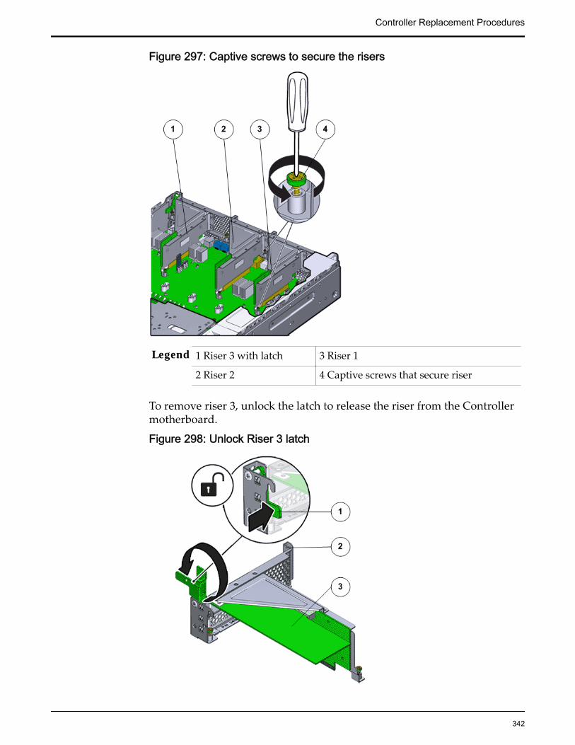
Figure 297: Captive screws to secure the risers
Legend 1 Riser 3 with latch 3 Riser 1
2 Riser 2 4 Captive screws that secure riser
To remove riser 3, unlock the latch to release the riser from the Controllermotherboard.
Figure 298: Unlock Riser 3 latch
Controller Replacement Procedures
342
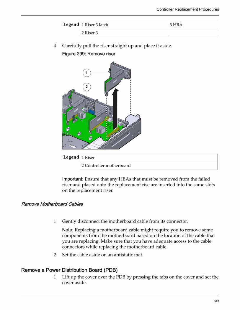
Legend 1 Riser 3 latch 3 HBA
2 Riser 3
4 Carefully pull the riser straight up and place it aside.
Figure 299: Remove riser
Legend 1 Riser
2 Controller motherboard
Important: Ensure that any HBAs that must be removed from the failedriser and placed onto the replacement rise are inserted into the same slotson the replacement riser.
Remove Motherboard Cables
1 Gently disconnect the motherboard cable from its connector.
Note: Replacing a motherboard cable might require you to remove somecomponents from the motherboard based on the location of the cable thatyou are replacing. Make sure that you have adequate access to the cableconnectors while replacing the motherboard cable.
2 Set the cable aside on an antistatic mat.
Remove a Power Distribution Board (PDB)1 Lift up the cover over the PDB by pressing the tabs on the cover and set the
cover aside.
Controller Replacement Procedures
343

Figure 300: Remove PDB cover
Legend 1 PDB cover
2 Power supply duct
3 PDB board
4 ControllerReplication Engine motherboard
Note: You must disconnect the PDB flat signal cable and the PSU ductwhen you lift up the PDB cover.
Figure 301: Disconnect PDB flat cable
Legend 1 PDB flat signal cable that connects the PDB to the motherboard
2 PDB bus bars
Controller Replacement Procedures
344

3 PDB
4 PDB cage
2 Remove the two Phillips screws that secure the PDB to the PDB cage usinga Phillips Number 2 screwdriver.
Figure 302: Remove PDB circuit board
Legend 1 PDB bus bars
2 PDB circuit board
3 Phillips screws that secure the PDB to the PDB cage
4 PDB cage
3 Slide out the PDB assembly from under the motherboard by lifting up themotherboard gently.
4 Remove the PDB assembly and place the PDB assembly on an antistaticmat.
Controller Replacement Procedures
345
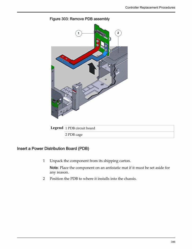
Figure 303: Remove PDB assembly
Legend 1 PDB circuit board
2 PDB cage
Insert a Power Distribution Board (PDB)
1 Unpack the component from its shipping carton.
Note: Place the component on an antistatic mat if it must be set aside forany reason.
2 Position the PDB to where it installs into the chassis.
Controller Replacement Procedures
346

Figure 304: PDB alignment
Legend 1 PDB circuit board
2 PDB cage
Note: The bus bars are forward and down.
3 Place the bus bars into the channels, and move the PDB rearward anddown onto the alignment pins.
4 Using a Phillips Number 2 screwdriver, loosely insert the four PhillipsNumber 2 screws that secure the PDB assembly onto the motherboard.
Controller Replacement Procedures
347

Figure 305: Insert PDB
Legend 1 Phillips screws that secure the PDB to the chassis
2 PDB
5 Using a Torx Number 10 screwdriver, loosely insert the 10 Torx Number 10screws that secure the motherboard to the Controller chassis starting fromone side.
6 Tighten all 10 Torx Number 10 screws and the four Phillips Number 2screws in a diagonal pattern.
7 Insert and tighten the two finger screws on the motherboard to lock themotherboard inside the Controller chassis.
Note: The two thumb screws on the motherboard secure the motherboardto the Controller chassis along with ten Torx Number 10 screws.
Insert Components on the ControllerInsert the necessary components on the Controller following theprocedures outlined below.Some components had to be removed from the Controller as a prerequisitefor access while replacing the failed component. These components mustbe reinstalled after completing the replacement.
Insert Motherboard Cables
Gently reconnect the motherboard cable to its connectors at both ends.
Controller Replacement Procedures
348

Insert a Riser
1 Lower the riser onto the Controller motherboard and press the riser edgeconnector securely into the socket.
Important: Ensure that any HBAs that must be removed from the failedriser and placed onto the replacement rise are inserted into the same slotson the replacement riser.
Figure 306: Insert riser
Legend 1 Riser
2 Controller motherboard
2 After the riser is seated properly inside the Controller, tighten the twocaptive Phillips screws on both sides of the riser to secure the riser on theController motherboard.
Controller Replacement Procedures
349

Figure 307: Captive screws to secure risers to the motherboard
Legend 1 Riser 3 with latch 3 Riser 1
2 Riser 2 4 Captive screws
To install riser 3, lock the latch to secure the riser to theControllerReplication Engine motherboard.
Figure 308: Riser 3 latch locked
Controller Replacement Procedures
350
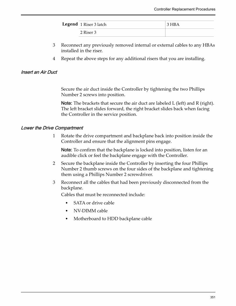
Legend 1 Riser 3 latch 3 HBA
2 Riser 3
3 Reconnect any previously removed internal or external cables to any HBAsinstalled in the riser.
4 Repeat the above steps for any additional risers that you are installing.
Insert an Air Duct
Secure the air duct inside the Controller by tightening the two PhillipsNumber 2 screws into position.
Note: The brackets that secure the air duct are labeled L (left) and R (right).The left bracket slides forward, the right bracket slides back when facingthe Controller in the service position.
Lower the Drive Compartment1 Rotate the drive compartment and backplane back into position inside the
Controller and ensure that the alignment pins engage.
Note: To confirm that the backplane is locked into position, listen for anaudible click or feel the backplane engage with the Controller.
2 Secure the backplane inside the Controller by inserting the four PhillipsNumber 2 thumb screws on the four sides of the backplane and tighteningthem using a Phillips Number 2 screwdriver.
3 Reconnect all the cables that had been previously disconnected from thebackplane.Cables that must be reconnected include:
• SATA or drive cable
• NV-DIMM cable
• Motherboard to HDD backplane cable
Controller Replacement Procedures
351
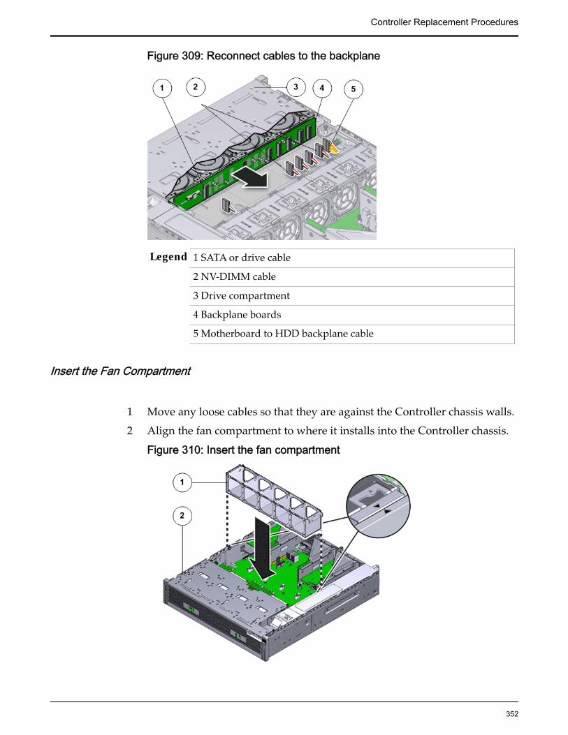
Figure 309: Reconnect cables to the backplane
Legend 1 SATA or drive cable
2 NV-DIMM cable
3 Drive compartment
4 Backplane boards
5 Motherboard to HDD backplane cable
Insert the Fan Compartment
1 Move any loose cables so that they are against the Controller chassis walls.
2 Align the fan compartment to where it installs into the Controller chassis.
Figure 310: Insert the fan compartment
Controller Replacement Procedures
352

Legend 1 Fan compartment
2 Controller chassis
Note: The single arrow on the right end of the fan compartment aligns withthe single arrow on the power supply bay.
3 Slowly lower the fan compartment into the Controller chassis, gentlyworking the cables into the gaps between the fan compartment and thechassis walls.
4 Verify that the fan compartment is properly seated, no cables are pinched,and the top surfaces of the fan compartment are flush with theControllerReplication Engine chassis.
Insert a Fan Module
Insert the replacement fan module into the Controller.
Figure 311: Insert fan module
Legend 1 Controller chassis
2 Fan compartment
3 Fan module
Note: Press down on the fan module and apply firm pressure to fully seatthe fan module into the fan compartment. The fan modules are notched toensure that they are installed in the correct orientation.
Controller Replacement Procedures
353

Note: Repeat for each additional fan module.
Close the Controller Top Cover
Place the top cover of the Controller and tighten the two thumb screws atthe back of the Controller that secure the top cover.
Figure 312: Close Controller top cover
Legend 1 Thumb screws
2 Controller top cover
3 Controller
Insert a Power Supply1 Unpack the component from its shipping carton.
Note: Place the component on an antistatic mat if it must be set aside forany reason.
2 Slide the replacement power supply into the power supply compartment atthe back of the Controller until it is fully seated.
Controller Replacement Procedures
354
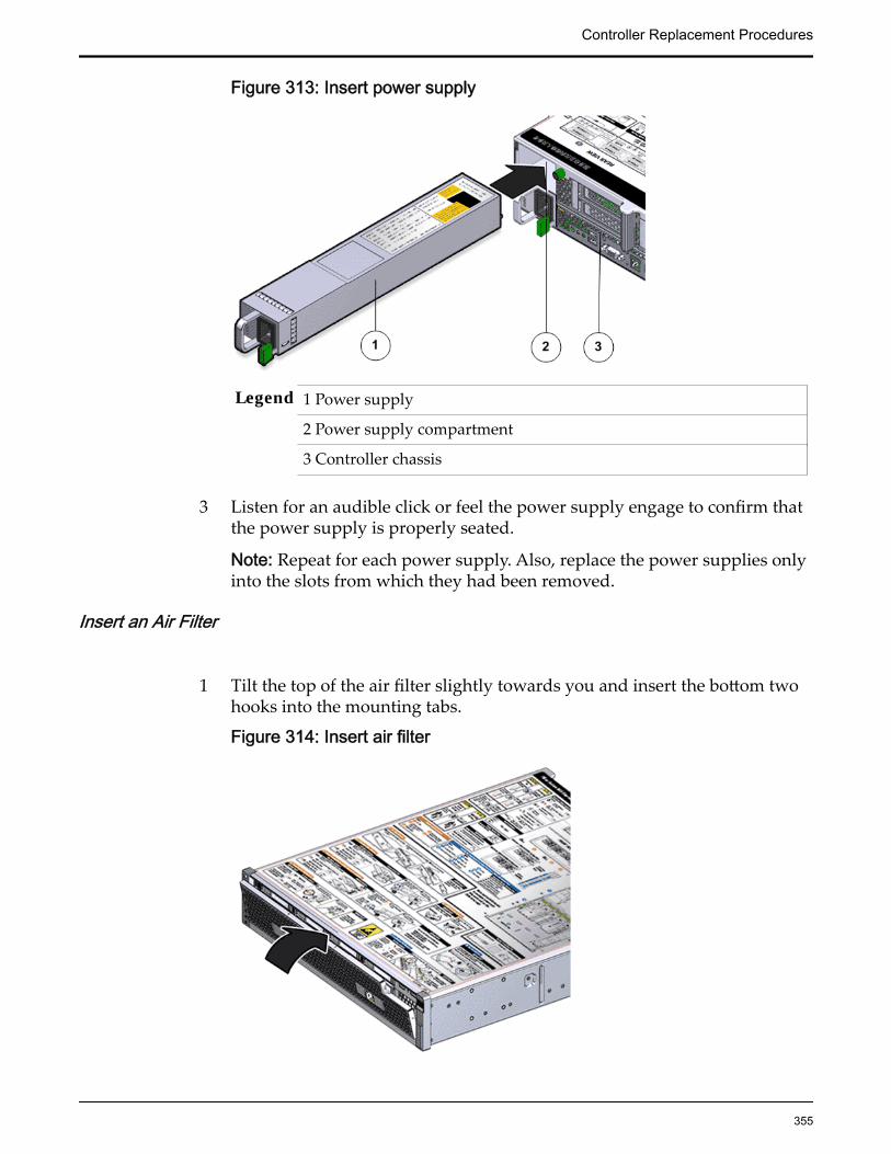
Figure 313: Insert power supply
Legend 1 Power supply
2 Power supply compartment
3 Controller chassis
3 Listen for an audible click or feel the power supply engage to confirm thatthe power supply is properly seated.
Note: Repeat for each power supply. Also, replace the power supplies onlyinto the slots from which they had been removed.
Insert an Air Filter
1 Tilt the top of the air filter slightly towards you and insert the bottom twohooks into the mounting tabs.
Figure 314: Insert air filter
Controller Replacement Procedures
355
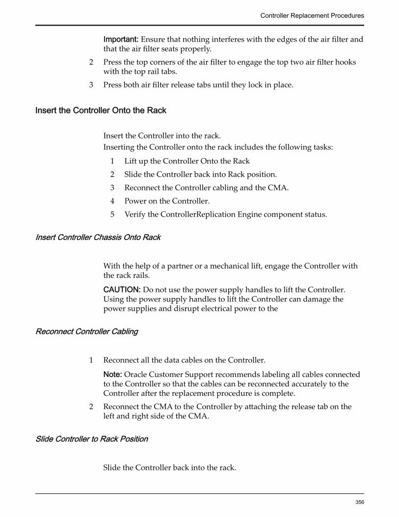
Important: Ensure that nothing interferes with the edges of the air filter andthat the air filter seats properly.
2 Press the top corners of the air filter to engage the top two air filter hookswith the top rail tabs.
3 Press both air filter release tabs until they lock in place.
Insert the Controller Onto the Rack
Insert the Controller into the rack.Inserting the Controller onto the rack includes the following tasks:
1 Lift up the Controller Onto the Rack
2 Slide the Controller back into Rack position.
3 Reconnect the Controller cabling and the CMA.
4 Power on the Controller.
5 Verify the ControllerReplication Engine component status.
Insert Controller Chassis Onto Rack
With the help of a partner or a mechanical lift, engage the Controller withthe rack rails.
CAUTION: Do not use the power supply handles to lift the Controller.Using the power supply handles to lift the Controller can damage thepower supplies and disrupt electrical power to the
Reconnect Controller Cabling
1 Reconnect all the data cables on the Controller.
Note: Oracle Customer Support recommends labeling all cables connectedto the Controller so that the cables can be reconnected accurately to theController after the replacement procedure is complete.
2 Reconnect the CMA to the Controller by attaching the release tab on theleft and right side of the CMA.
Slide Controller to Rack Position
Slide the Controller back into the rack.
Controller Replacement Procedures
356
Note: You must release the rail locking mechanism to slide the Controllerchassis back into the rack.
Power On the Controller
Power on the Controller using the power button and the ILOM webinterface.
Note: As soon as the power cords are connected to the Controller, standbypower is applied. In standby power mode, the Power/OK LED on theController front panel blinks every five seconds or so. However, to applymain power to the Controller, you must use the power button and the webinterface. When main power is applied to the Controller, the green Power/OK LED on the front panel of the Controller blinks steadily. When theController BIOS has completed booting, the OK LED remains lit.
Verify Controller Component Status
1 From Guided Maintenance, verify that the status is Normal.
You can also verify the status by navigating to System > Hardware andthen selecting a chassis. The Overview page for the selected chassis lists thestatus of each component.
Note: The Controller status will be visible several minutes after beingpowered on.
2 Review the status of the LEDs to confirm a status of Normal.
Controller Replacement Procedures
357

CHAPTER 4
Drive Enclosure Replacement Procedures
Drive Enclosure OverviewDrive Enclosures are used as back-end storage for the Oracle Flash StorageSystem. The Oracle FS System can be configured for as many as 30 DriveEnclosures. The two types of Drive Enclosure are the DE2-24P Drive Enclosureand the DE2-24C Drive Enclosure. Both Drive Enclosure types can co-exist in thesame system.
Drive Enclosure are high-availability, serial-attached SCSI (SAS-2) storageenclosures. The DE2-24P Drive Enclosure has a 2U chassis that supports 24 smallform factor (SFF), 2.5-inch (6.35-cm) hard disk drives (HDDs). The DE2-24P DriveEnclosure also supports configurations with seven, 13, or 19 solid state drives(SSDs). The DE2-24C Drive Enclosure has a 4U chassis that supports 24 largeform factor (LFF), 3.5-inch (8.89-cm) HDDs.
The following figures show the front of the DE2-24P Drive Enclosure and theDE2-24C Drive Enclosure.
Figure 315: DE2-24P Drive Enclosure (front view)
358

Figure 316: DE2-24C Drive Enclosure (front view)
Both types of Drive Enclosures have the following physical configuration:
• Two hot-serviceable I/O modules with two interface slots that comply withthe Storage Bridge Bay (SBB) standard
• Two hot-serviceable 580W power cooling modules with dual load-sharingpower supplies and integrated fans
• 19-inch rack‑compatible enclosure
• Front access to all drives
• Back access to the I/O modules and the power cooling modules
• LEDs with status information for the I/O modules, the drives, and thepower cooling modules
The following figures show the back of the DE2-24P Drive Enclosure and theDE2-24C Drive Enclosure.
Drive Enclosure Replacement Procedures
359

Figure 317: DE2-24P Drive Enclosure (back view)
Figure 318: DE2-24C Drive Enclosure (back view)
Drive Enclosure Drive ReplacementEach Drive Enclosure has drives located on the front of the chassis. Drives arecustomer replaceable units (CRUs). Replacing a drive is a hot-serviceableprocess.
The DE2-24P Drive Enclosure supports the following drive configurationoptions:
• 300GB hard disk drives (HDDs) fully populated with 24 drives
• 900GB HDDs fully populated with 24 drives
• 400GB solid state drives (SSDs) in the following configurations:
• Six drives and one spare
Drive Enclosure Replacement Procedures
360

• 12 drives and one spare
• Six drive upgrade to the current configuration
• 1.6TB SSDs with the following configurations:
• Six drives and one spare
• 12 drives and one spare
• 18 drives and one spare
• Six drive upgrade to the current configuration
Important: The Oracle FS System accepts only Oracle-supplied drives. Thecapacity and the type of a replacement drive must be same as the other drives inthe Drive Enclosure.
The 24 drive locations are numbered 0 to 23 from left to right. The followingfigure shows the location of the drives on the DE2-24P Drive Enclosure.
Figure 319: DE2-24P Drive Enclosure drives
The DE2-24C Drive Enclosure can only be configured with 24, 4TB HDDs.
The 24 drive locations are numbered 0 to 23 from the lower left of the DriveEnclosure to the upper right of the Drive Enclosure. The following figure showsthe location of the drives on the DE2-24C Drive Enclosure.
Figure 320: DE2-24C Drive Enclosure drives
CAUTION: Make sure you can replace the FRU or CRU within 10 minutes ofremoving the FRU or CRU. Do not remove a FRU or CRU if you cannot replace itwithin 10 minutes with a FRU or CRU or with a filler panel. If a FRU or CRU slotis left empty, the system can overheat due to improper airflow.
Drive Enclosure Replacement Procedures
361

Important: Make sure that you remove the correct drive. Removing a drive otherthan the failed drive can disrupt data access and possibly corrupt data.
The system generates an alert to notify you of a failed drive. The system alsonotifies you when it detects that a drive might fail soon.
Replace a Drive Enclosure DriveA failed Drive Enclosure drive degrades data throughput. Additionally, if morethan one drive begins to fail, data loss can occur. Replace a failed drive with adrive of the same type and capacity as soon as possible.
Prerequisites: • Before handling a component, touch a grounded surface todischarge any static electricity.
• Attach an electrostatic discharge (ESD) wrist strap to yourwrist, and stand on an ESD mat while replacingcomponents.
• Make sure that the replacement drive has the samecapacity and same type as the drive to be replaced.
Important: After you initiate Guided Maintenance to prepare the system forreplacing a drive, you must complete the procedure. Do not cancel thereplacement process after the replacement process has started. Canceling thereplacement process can result in loss of data.
Procedure Overview
1 Prepare a Drive Enclosure for Component Replacement
2 Remove a Drive
3 Insert a Drive
4 Verify the Status of a Drive Enclosure Component
Related LinksGuided Maintenance OverviewDrive Enclosure ComponentsGuided Maintenance Replaceable Components
Prepare a Drive Enclosure for Component Replacement1 From Oracle FS System Manager (GUI), navigate to System > Hardware.
2 Select Drive Enclosures.The GUI displays the Drive Enclosures Overview page. The DriveEnclosures Overview page displays the status of the Drive Enclosurecomponents.
3 Select the Drive Enclosure containing the component that you want toreplace.
4 Select Actions > View.
Drive Enclosure Replacement Procedures
362

The View Drive Enclosure dialog displays the list of replaceable DriveEnclosure components in the Replaceable Unit list.
5 From the Replaceable Unit list, select the component that you want toreplace and click Replace Component.Guided Maintenance displays the Introduction page, and guides youthrough the steps to replace the Drive Enclosure component.
6 Click Next.Guided Maintenance displays the Identify Hardware dialog.
7 From the Identify Hardware dialog, specify how you want to identify thechassis so that you can locate it in the data center.
You can select one of the following methods to identify the chassis:
Identify Flashes the LEDs on the chassis that contains the failedcomponent.
ReverseIdentify
Flashes the LEDs on all of the chassis in the system exceptfor the chassis that contains the failed component.
8 Click Next.Based on the method you selected to identify the chassis, thecorresponding LEDs flash to help you locate the chassis in the data center.
9 Click Next.
Guided Maintenance completes the process of preparing the system forDrive Enclosure replacement. After Guided Maintenance prepares theDrive Enclosure for replacing a component, it displays the ReplaceHardware dialog box. The Replace Hardware dialog box instructs you toreplace the component. You also receive a System Alert informing you thatthe component is ready for removal. To review System Alerts, selectSystem > Alerts and Events > System Alerts.
Remove a Drive1 On the failed drive, press the drive carrier latch to disengage the drive.
Drive Enclosure Replacement Procedures
363

Figure 321: A DE2-24P Drive Enclosure drive and drive carrier latch
Legend 1 A drive 2 Drive carrier latch (closeup)
Figure 322: A DE2-24C Drive Enclosure drive and drive carrier latch
Legend 1 A drive 2 Drive carrier latch (closeup)
2 On the failed drive, pull the drive carrier handle fully open to unlock andpartially eject the drive from the Drive Enclosure chassis.
CAUTION: Do not force open the drive carrier handle. You can damage thedrive carrier handle if you apply too much force.
Drive Enclosure Replacement Procedures
364
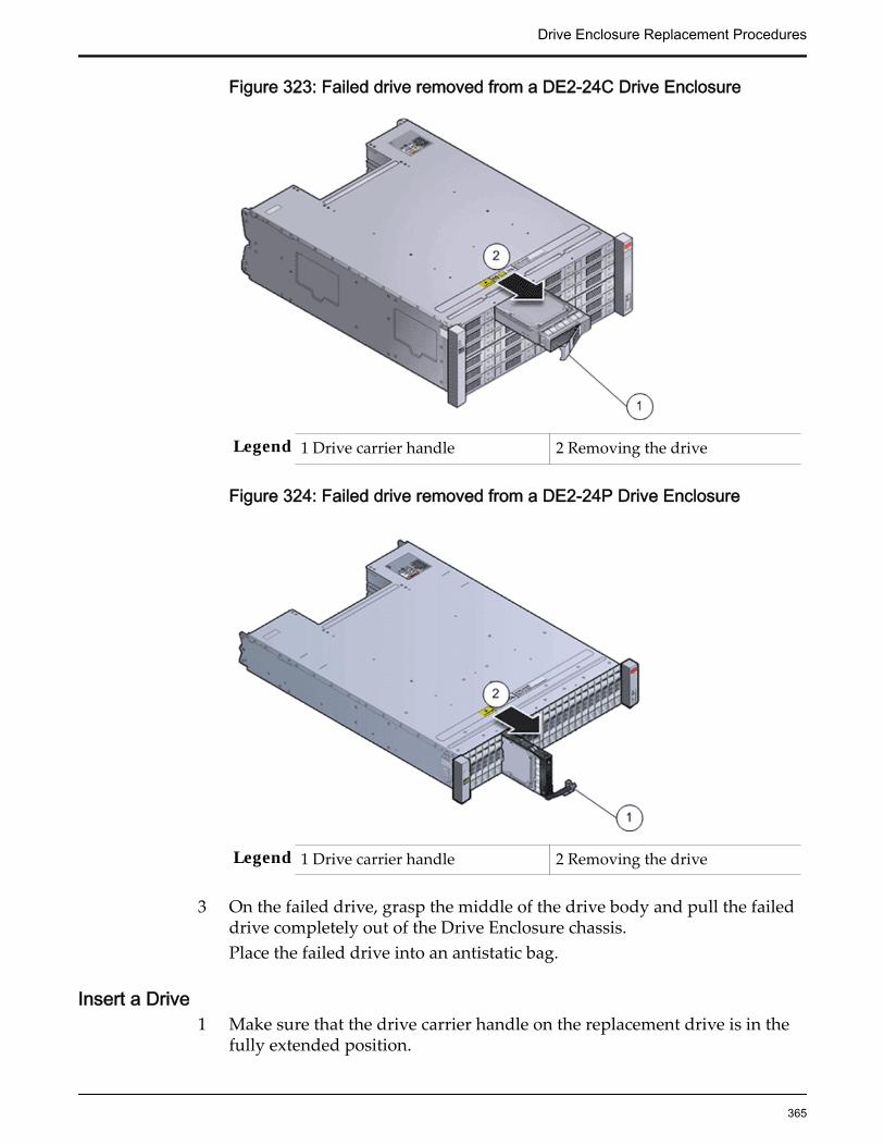
Figure 323: Failed drive removed from a DE2-24C Drive Enclosure
Legend 1 Drive carrier handle 2 Removing the drive
Figure 324: Failed drive removed from a DE2-24P Drive Enclosure
Legend 1 Drive carrier handle 2 Removing the drive
3 On the failed drive, grasp the middle of the drive body and pull the faileddrive completely out of the Drive Enclosure chassis.Place the failed drive into an antistatic bag.
Insert a Drive1 Make sure that the drive carrier handle on the replacement drive is in the
fully extended position.
Drive Enclosure Replacement Procedures
365
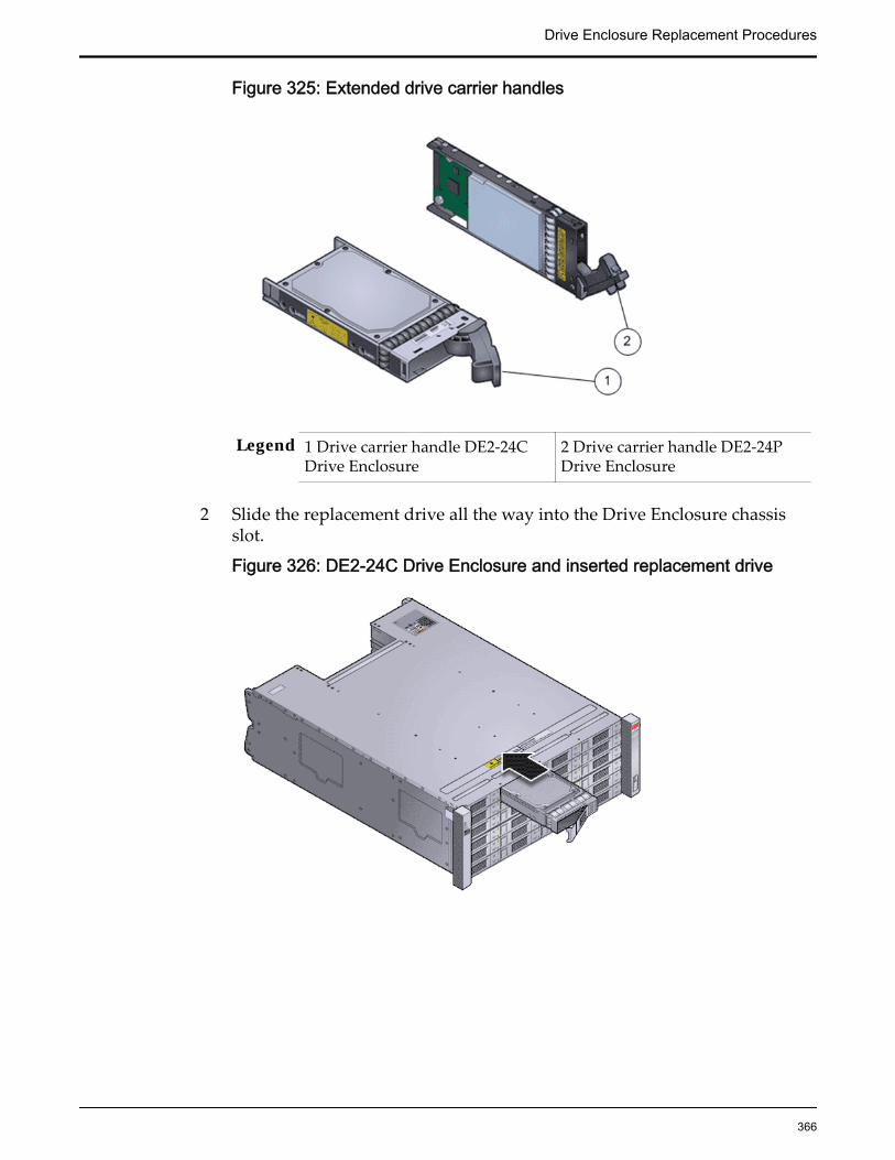
Figure 325: Extended drive carrier handles
Legend 1 Drive carrier handle DE2-24CDrive Enclosure
2 Drive carrier handle DE2-24PDrive Enclosure
2 Slide the replacement drive all the way into the Drive Enclosure chassisslot.
Figure 326: DE2-24C Drive Enclosure and inserted replacement drive
Drive Enclosure Replacement Procedures
366
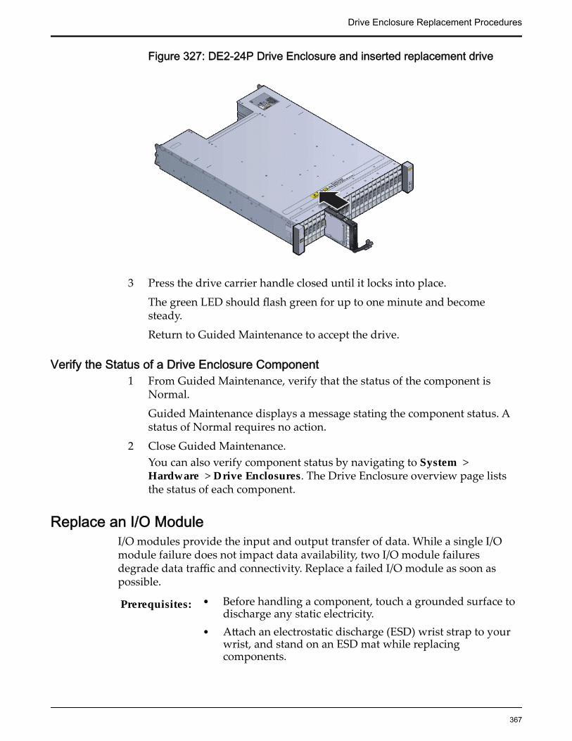
Figure 327: DE2-24P Drive Enclosure and inserted replacement drive
3 Press the drive carrier handle closed until it locks into place.
The green LED should flash green for up to one minute and becomesteady.
Return to Guided Maintenance to accept the drive.
Verify the Status of a Drive Enclosure Component1 From Guided Maintenance, verify that the status of the component is
Normal.
Guided Maintenance displays a message stating the component status. Astatus of Normal requires no action.
2 Close Guided Maintenance.You can also verify component status by navigating to System >Hardware > Drive Enclosures. The Drive Enclosure overview page liststhe status of each component.
Replace an I/O ModuleI/O modules provide the input and output transfer of data. While a single I/Omodule failure does not impact data availability, two I/O module failuresdegrade data traffic and connectivity. Replace a failed I/O module as soon aspossible.
Prerequisites: • Before handling a component, touch a grounded surface todischarge any static electricity.
• Attach an electrostatic discharge (ESD) wrist strap to yourwrist, and stand on an ESD mat while replacingcomponents.
Drive Enclosure Replacement Procedures
367
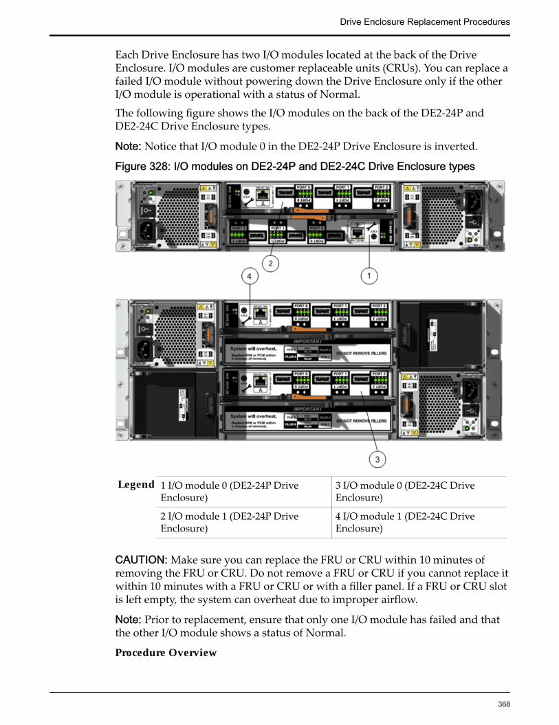
Each Drive Enclosure has two I/O modules located at the back of the DriveEnclosure. I/O modules are customer replaceable units (CRUs). You can replace afailed I/O module without powering down the Drive Enclosure only if the otherI/O module is operational with a status of Normal.
The following figure shows the I/O modules on the back of the DE2-24P andDE2-24C Drive Enclosure types.
Note: Notice that I/O module 0 in the DE2-24P Drive Enclosure is inverted.
Figure 328: I/O modules on DE2-24P and DE2-24C Drive Enclosure types
Legend 1 I/O module 0 (DE2-24P DriveEnclosure)
3 I/O module 0 (DE2-24C DriveEnclosure)
2 I/O module 1 (DE2-24P DriveEnclosure)
4 I/O module 1 (DE2-24C DriveEnclosure)
CAUTION: Make sure you can replace the FRU or CRU within 10 minutes ofremoving the FRU or CRU. Do not remove a FRU or CRU if you cannot replace itwithin 10 minutes with a FRU or CRU or with a filler panel. If a FRU or CRU slotis left empty, the system can overheat due to improper airflow.
Note: Prior to replacement, ensure that only one I/O module has failed and thatthe other I/O module shows a status of Normal.
Procedure Overview
Drive Enclosure Replacement Procedures
368
1 Prepare a Drive Enclosure for Component Replacement
2 Remove an I/O Module
3 Insert an I/O Module
4 Verify the Status of a Drive Enclosure Component
Related LinksGuided Maintenance OverviewDrive Enclosure ComponentsGuided Maintenance Replaceable Components
Prepare a Drive Enclosure for Component Replacement1 From Oracle FS System Manager (GUI), navigate to System > Hardware.2 Select Drive Enclosures.
The GUI displays the Drive Enclosures Overview page. The DriveEnclosures Overview page displays the status of the Drive Enclosurecomponents.
3 Select the Drive Enclosure containing the component that you want toreplace.
4 Select Actions > View.The View Drive Enclosure dialog displays the list of replaceable DriveEnclosure components in the Replaceable Unit list.
5 From the Replaceable Unit list, select the component that you want toreplace and click Replace Component.Guided Maintenance displays the Introduction page, and guides youthrough the steps to replace the Drive Enclosure component.
6 Click Next.Guided Maintenance displays the Identify Hardware dialog.
7 From the Identify Hardware dialog, specify how you want to identify thechassis so that you can locate it in the data center.
You can select one of the following methods to identify the chassis:
Identify Flashes the LEDs on the chassis that contains the failedcomponent.
ReverseIdentify
Flashes the LEDs on all of the chassis in the system exceptfor the chassis that contains the failed component.
8 Click Next.Based on the method you selected to identify the chassis, thecorresponding LEDs flash to help you locate the chassis in the data center.
9 Click Next.
Guided Maintenance completes the process of preparing the system forDrive Enclosure replacement. After Guided Maintenance prepares the
Drive Enclosure Replacement Procedures
369
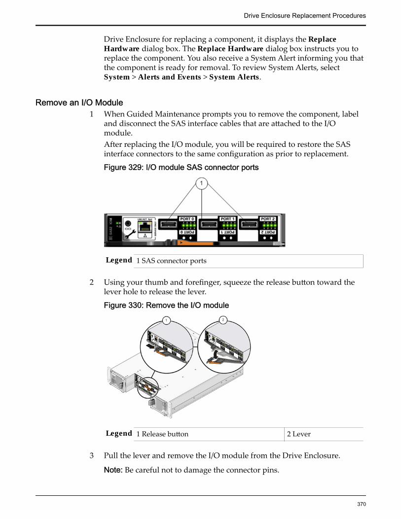
Drive Enclosure for replacing a component, it displays the ReplaceHardware dialog box. The Replace Hardware dialog box instructs you toreplace the component. You also receive a System Alert informing you thatthe component is ready for removal. To review System Alerts, selectSystem > Alerts and Events > System Alerts.
Remove an I/O Module1 When Guided Maintenance prompts you to remove the component, label
and disconnect the SAS interface cables that are attached to the I/Omodule.After replacing the I/O module, you will be required to restore the SASinterface connectors to the same configuration as prior to replacement.
Figure 329: I/O module SAS connector ports
Legend 1 SAS connector ports
2 Using your thumb and forefinger, squeeze the release button toward thelever hole to release the lever.
Figure 330: Remove the I/O module
Legend 1 Release button 2 Lever
3 Pull the lever and remove the I/O module from the Drive Enclosure.
Note: Be careful not to damage the connector pins.
Drive Enclosure Replacement Procedures
370

Insert an I/O Module1 With the lever of the replacement I/O module in the open position, slide
the I/O module into the Drive Enclosure chassis.
Note: Be careful not to damage the connector pins.
Note: Notice that I/O module 0 in the DE2-24P Drive Enclosure is inverted.
2 As the replacement I/O module contacts the chassis midplane, close thelever and reattach the release button.To confirm that the replacement I/O module is properly closed, listen foran audible click or feel the replacement I/O module engage with thechassis midplane.
Figure 331: Insert the I/O module
Legend 1 Lever
2 Release button
3 Reconnect the SAS interface cables to the SAS connector ports on the I/Omodule.Make sure to connect the SAS interface cables in the exact sameconfiguration as prior to replacement.
Figure 332: I/O module SAS connector ports
Drive Enclosure Replacement Procedures
371

Legend 1 SAS connector ports
4 Wait approximately 60 seconds for the I/O module to restart.When the startup process completes, the following indicators should bepresent:
• The Power LED emits a steady green light.
• The Fault LED is off.
• All four Activity LEDs emit a green light for each SAS-2 port that hasan SAS interface cable connected to it.
Verify the Status of a Drive Enclosure Component1 From Guided Maintenance, verify that the status of the component is
Normal.
Guided Maintenance displays a message stating the component status. Astatus of Normal requires no action.
2 Close Guided Maintenance.You can also verify component status by navigating to System >Hardware > Drive Enclosures. The Drive Enclosure overview page liststhe status of each component.
Replace a Power Cooling ModuleThe power cooling modules provide redundant power control and cooling of thesystem. If one power cooling module fails, the other power cooling modulemaintains the power supply and cooling while you replace the failed powercooling module. Electrical overload, inadequate internal and external airflow,dirt and dust, incorrect input voltage, or a short circuit can damage a powercooling module. Replace a failed power cooling module immediately; otherwise,damage from overheating and data loss can occur.
Prerequisites: • Before handling a component, touch a grounded surface todischarge any static electricity.
• Attach an electrostatic discharge (ESD) wrist strap to yourwrist, and stand on an ESD mat while replacingcomponents.
WARNING: Do not remove covers from the power coolingmodules. Power cooling modules produce a high-energy hazard.
Each Drive Enclosure has two power cooling modules located at the back of theDrive Enclosure. Power cooling modules are customer replaceable units (CRUs).You can replace a failed power cooling module without powering down theDrive Enclosure only if the other power cooling module is operational with astatus of Normal.
Drive Enclosure Replacement Procedures
372
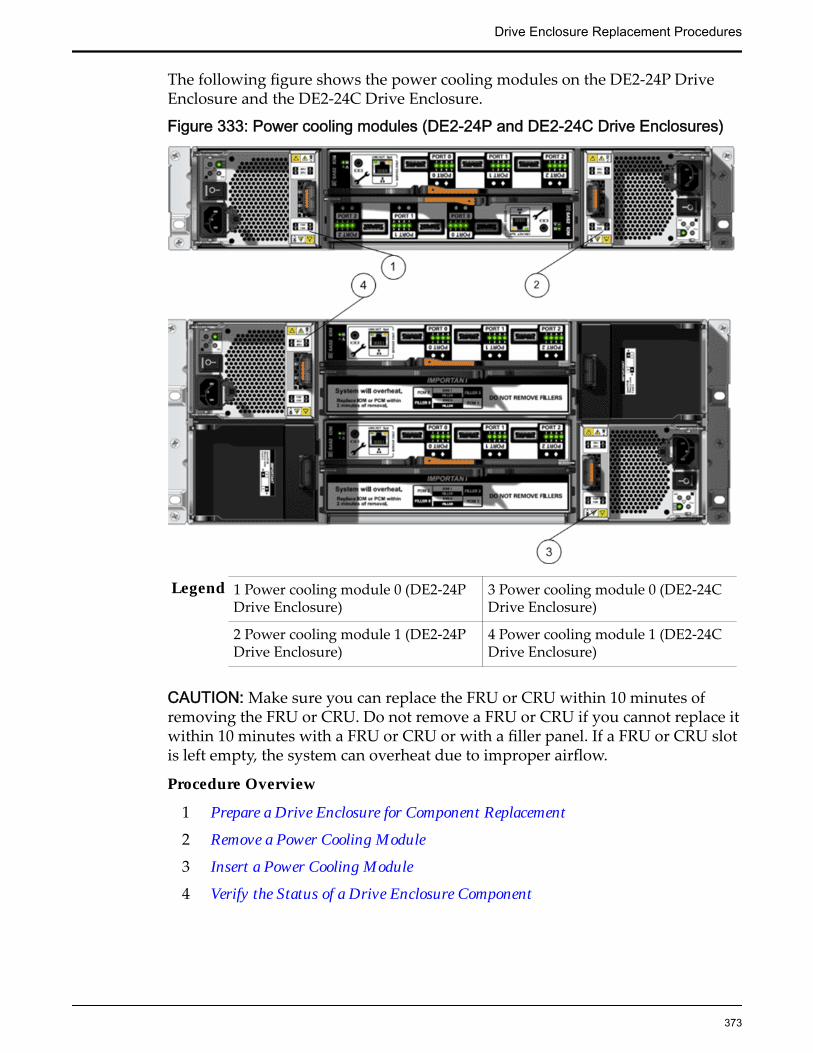
The following figure shows the power cooling modules on the DE2-24P DriveEnclosure and the DE2-24C Drive Enclosure.
Figure 333: Power cooling modules (DE2-24P and DE2-24C Drive Enclosures)
Legend 1 Power cooling module 0 (DE2-24PDrive Enclosure)
3 Power cooling module 0 (DE2-24CDrive Enclosure)
2 Power cooling module 1 (DE2-24PDrive Enclosure)
4 Power cooling module 1 (DE2-24CDrive Enclosure)
CAUTION: Make sure you can replace the FRU or CRU within 10 minutes ofremoving the FRU or CRU. Do not remove a FRU or CRU if you cannot replace itwithin 10 minutes with a FRU or CRU or with a filler panel. If a FRU or CRU slotis left empty, the system can overheat due to improper airflow.
Procedure Overview
1 Prepare a Drive Enclosure for Component Replacement
2 Remove a Power Cooling Module
3 Insert a Power Cooling Module
4 Verify the Status of a Drive Enclosure Component
Drive Enclosure Replacement Procedures
373
Related LinksGuided Maintenance OverviewDrive Enclosure ComponentsGuided Maintenance Replaceable Components
Prepare a Drive Enclosure for Component Replacement1 From Oracle FS System Manager (GUI), navigate to System > Hardware.
2 Select Drive Enclosures.The GUI displays the Drive Enclosures Overview page. The DriveEnclosures Overview page displays the status of the Drive Enclosurecomponents.
3 Select the Drive Enclosure containing the component that you want toreplace.
4 Select Actions > View.The View Drive Enclosure dialog displays the list of replaceable DriveEnclosure components in the Replaceable Unit list.
5 From the Replaceable Unit list, select the component that you want toreplace and click Replace Component.Guided Maintenance displays the Introduction page, and guides youthrough the steps to replace the Drive Enclosure component.
6 Click Next.Guided Maintenance displays the Identify Hardware dialog.
7 From the Identify Hardware dialog, specify how you want to identify thechassis so that you can locate it in the data center.
You can select one of the following methods to identify the chassis:
Identify Flashes the LEDs on the chassis that contains the failedcomponent.
ReverseIdentify
Flashes the LEDs on all of the chassis in the system exceptfor the chassis that contains the failed component.
8 Click Next.Based on the method you selected to identify the chassis, thecorresponding LEDs flash to help you locate the chassis in the data center.
9 Click Next.
Guided Maintenance completes the process of preparing the system forDrive Enclosure replacement. After Guided Maintenance prepares theDrive Enclosure for replacing a component, it displays the ReplaceHardware dialog box. The Replace Hardware dialog box instructs you toreplace the component. You also receive a System Alert informing you thatthe component is ready for removal. To review System Alerts, selectSystem > Alerts and Events > System Alerts.
Drive Enclosure Replacement Procedures
374

Remove a Power Cooling Module1 When Guided Maintenance prompts you to remove the component, power
off the failed power cooling module.
Note: Do not power off the healthy power cooling module.
2 Disconnect the power cord tie strap from the faulted power coolingmodule.
3 Unplug the power cord from the failed power cooling module.
4 Release the attachment lever.
To release the attachment lever, squeeze together the latch and the oppositeside of the failed power cooling module.
Figure 334: Attachment lever and latch on the power cooling module
Legend 1 Power cooling module 3 Attachment lever
2 Latch
5 Gently pull the failed power cooling module out of the Drive Enclosurechassis.
Note: Be careful not to damage the connector pins.
Insert a Power Cooling ModuleBefore sliding a power cooling into the Drive Enclosure, ensure that the powercooling module is oriented correctly. To ensure correct orientation, align the latchon the power cooling module with the inner area of the Drive Enclosure.
CAUTION: Inserting a power cooling module that is not oriented correctly into aDrive Enclosure can damage the power cooling module and the Drive Enclosure.
Drive Enclosure Replacement Procedures
375
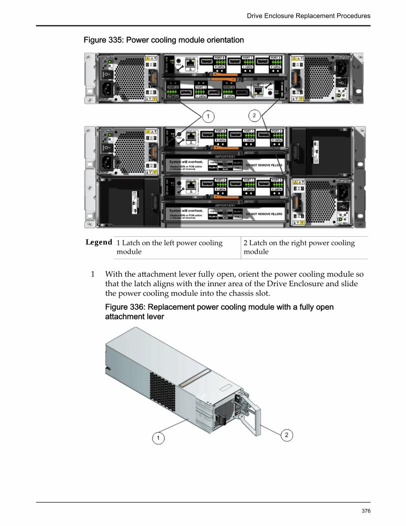
Figure 335: Power cooling module orientation
Legend 1 Latch on the left power coolingmodule
2 Latch on the right power coolingmodule
1 With the attachment lever fully open, orient the power cooling module sothat the latch aligns with the inner area of the Drive Enclosure and slidethe power cooling module into the chassis slot.
Figure 336: Replacement power cooling module with a fully openattachment lever
Drive Enclosure Replacement Procedures
376

Legend 1 Power cooling module 2 Opened attachment lever
2 As the replacement power cooling module contacts the Drive Enclosurechassis midplane, close the attachment lever.To confirm that the replacement power cooling module is properly closed,listen for an audible click or feel the part engage with the Drive Enclosurechassis midplane.
Figure 337: Replacement power cooling module (right side)
Legend 1 Slide replacement power coolingmodule into Drive Enclosure chassis slot
2 Close the attachmentlever
3 On the replacement power cooling module, make sure that the powerswitch is off.
4 Plug the power cord into the replacement power cooling module.5 Attach the power cord tie strap to the power cord.6 Power on the replacement power cooling module.
When the power-on process completes, the following indicators should bepresent:
• The Power status LED emits a steady green light.
• All other LEDs are off.
Verify the Status of a Drive Enclosure Component1 From Guided Maintenance, verify that the status of the component is
Normal.
Guided Maintenance displays a message stating the component status. Astatus of Normal requires no action.
2 Close Guided Maintenance.You can also verify component status by navigating to System >Hardware > Drive Enclosures. The Drive Enclosure overview page liststhe status of each component.
Drive Enclosure Replacement Procedures
377
Replace a Drive Enclosure ChassisIf a component inside of a Drive Enclosure is damaged, data loss can occur.Replace the Drive Enclosure as soon as possible.
Note: Replacement of the Drive Enclosure requires assistance from OracleCustomer Support.
You have the following options when replacing a Drive Enclosure:
Replace a DriveEnclosurewhile data isaccessible
To ensure that the data remains accessible to users while theDrive Enclosure is offline, migrate the data off of the DriveEnclosure prior to replacing it. The Oracle FS System continuesto operate without a loss of data availability.
Important: Migrating the data off of a Drive Enclosure can takeseveral hours, depending upon the Drive Enclosure’s usedcapacity. When the data migration completes, you receive asystem alert informing you that the data has been migrated.
Migrating data requires that the Drive Enclosure is functionaland enough free capacity must exist on the other DriveEnclosures in the same Storage Domain.
Replace a DriveEnclosurewhile data isinaccessible
If the Drive Enclosure is not functional, or if enough freecapacity does not exist on the other Drive Enclosures in thesame Storage Domain, shut down the Oracle FS System priorto replacing the Drive Enclosure. Users cannot access the datawhile the system is offline; however, the replacementprocedure requires less than one hour to complete comparedto several hours necessary to migrate the data.The data remains on the drives. During the replacementprocedure, you remove those drives from the original DriveEnclosure and insert them into the replacement DriveEnclosure. When the replacement Drive Enclosure joins thesystem, the system recognizes the original drives and theoriginal drive groups.
Note: Prior to shutting down the system, determine whetherthe primary drive group in the Storage Domain is with theDrive Enclosure that you plan to replace. If the primary drivegroup is with the Drive Enclosure that you plan to replace,select a drive group from a different Drive Enclosure to be theprimary drive group. Then, proceed with shutting down thesystem.
Note: You do not use Guided Maintenance to replace a Drive Enclosure.
Procedure Overview
• Replace a Drive Enclosure (Data Accessible)
• Replace a Drive Enclosure (Data Inaccessible)
Drive Enclosure Replacement Procedures
378

Replace a Drive Enclosure (Data Accessible)Prerequisites: • Before handling a component, touch a grounded surface to
discharge any static electricity.• Attach an electrostatic discharge (ESD) wrist strap to your
wrist, and stand on an ESD mat while replacingcomponents.
• Ensure that you have a Phillips Number 2 screwdriverwith at least a four-inch shaft.
CAUTION: The Drive Enclosures are heavy. Work with a partner or use amechanical lift for assistance. The DE2-24C Drive Enclosure weighsapproximately 102 lbs (46 kg) and the DE2-24P Drive Enclosure weighsapproximately 53 lbs (24 kg). Be careful not to drop a Drive Enclosure. Droppinga Drive Enclosure can cause damage and can reduce the life of the drives.
Procedure Overview
1 Migrate Data Off of a Drive Enclosure
2 Power Off a Drive Enclosure
3 Remove a Drive Enclosure
4 Insert a Replacement Drive Enclosure into a Rack (DE2-24P)
5 Insert a Replacement Drive Enclosure into a Rack (DE2-24C)
6 Power On a Drive Enclosure
7 Accept the Drives for a Replacement Drive Enclosure
8 Add Drive Groups to the Storage Domain
Migrate Data Off of a Drive Enclosure1 From Oracle FS System Manager (GUI), navigate to System > Storage
Domains.
2 From the list of Storage Domains, locate the Drive Enclosure that you wantto replace and select all of its associated drive groups.
Note: Make sure that you select all of the drive groups associated with theselected Drive Enclosure. A Drive Enclosure with hard disk drives (HDDs)has two drive groups. A Drive Enclosure with solid state drives (SSDs) canhave at least one drive group and as many as three drive groups.
3 Select Actions > Remove from Storage Domain.
The GUI displays the Remove from Storage Domain dialog.
4 Select a migration priority.
5 Click OK.
Drive Enclosure Replacement Procedures
379
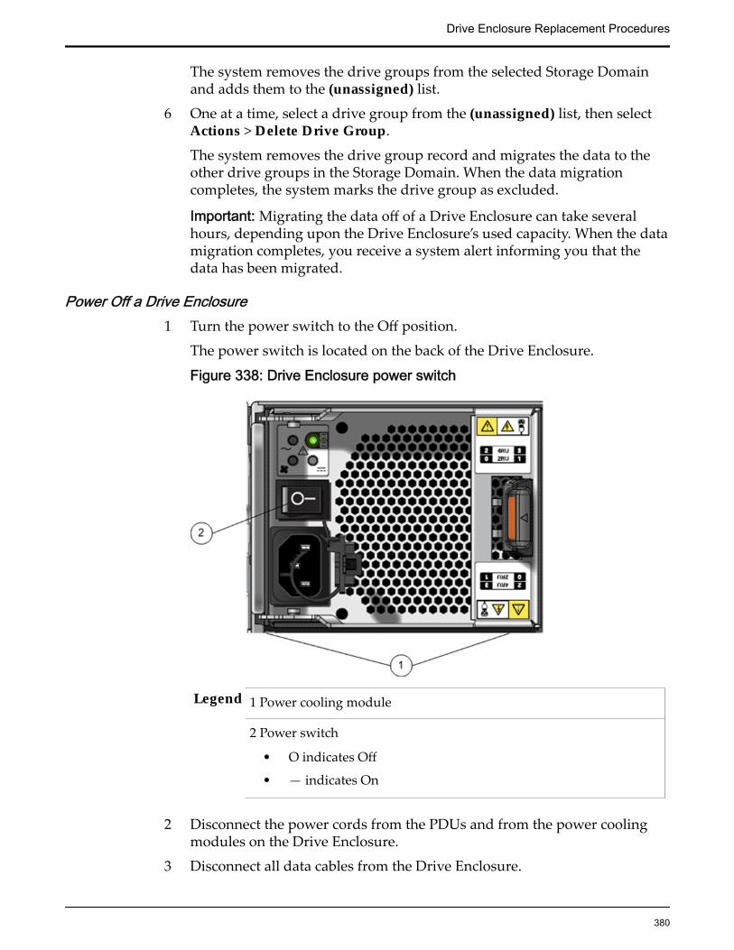
The system removes the drive groups from the selected Storage Domainand adds them to the (unassigned) list.
6 One at a time, select a drive group from the (unassigned) list, then selectActions > Delete Drive Group.
The system removes the drive group record and migrates the data to theother drive groups in the Storage Domain. When the data migrationcompletes, the system marks the drive group as excluded.
Important: Migrating the data off of a Drive Enclosure can take severalhours, depending upon the Drive Enclosure’s used capacity. When the datamigration completes, you receive a system alert informing you that thedata has been migrated.
Power Off a Drive Enclosure1 Turn the power switch to the Off position.
The power switch is located on the back of the Drive Enclosure.
Figure 338: Drive Enclosure power switch
Legend 1 Power cooling module
2 Power switch
• O indicates Off
• — indicates On
2 Disconnect the power cords from the PDUs and from the power coolingmodules on the Drive Enclosure.
3 Disconnect all data cables from the Drive Enclosure.
Drive Enclosure Replacement Procedures
380
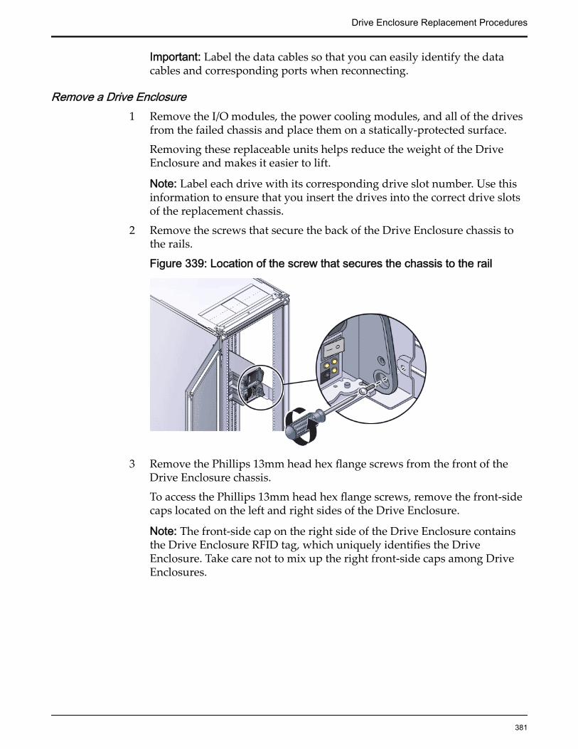
Important: Label the data cables so that you can easily identify the datacables and corresponding ports when reconnecting.
Remove a Drive Enclosure1 Remove the I/O modules, the power cooling modules, and all of the drives
from the failed chassis and place them on a statically-protected surface.
Removing these replaceable units helps reduce the weight of the DriveEnclosure and makes it easier to lift.
Note: Label each drive with its corresponding drive slot number. Use thisinformation to ensure that you insert the drives into the correct drive slotsof the replacement chassis.
2 Remove the screws that secure the back of the Drive Enclosure chassis tothe rails.
Figure 339: Location of the screw that secures the chassis to the rail
3 Remove the Phillips 13mm head hex flange screws from the front of theDrive Enclosure chassis.
To access the Phillips 13mm head hex flange screws, remove the front-sidecaps located on the left and right sides of the Drive Enclosure.
Note: The front-side cap on the right side of the Drive Enclosure containsthe Drive Enclosure RFID tag, which uniquely identifies the DriveEnclosure. Take care not to mix up the right front-side caps among DriveEnclosures.
Drive Enclosure Replacement Procedures
381
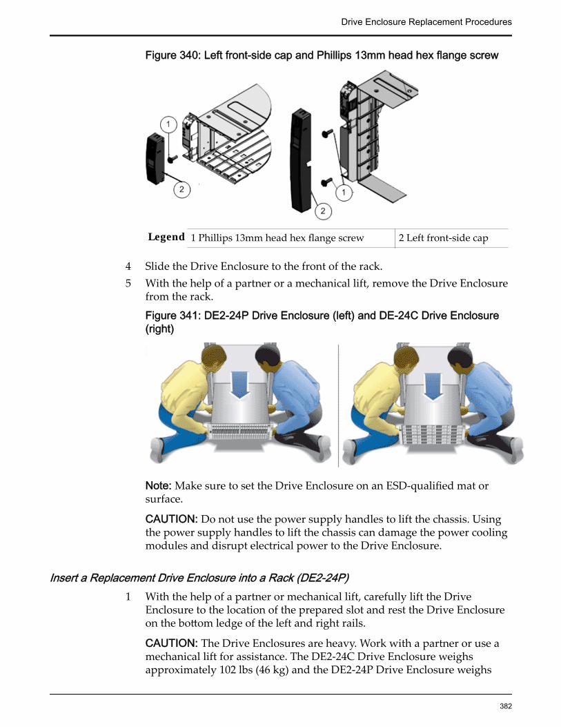
Figure 340: Left front-side cap and Phillips 13mm head hex flange screw
Legend 1 Phillips 13mm head hex flange screw 2 Left front-side cap
4 Slide the Drive Enclosure to the front of the rack.5 With the help of a partner or a mechanical lift, remove the Drive Enclosure
from the rack.
Figure 341: DE2-24P Drive Enclosure (left) and DE-24C Drive Enclosure(right)
Note: Make sure to set the Drive Enclosure on an ESD-qualified mat orsurface.
CAUTION: Do not use the power supply handles to lift the chassis. Usingthe power supply handles to lift the chassis can damage the power coolingmodules and disrupt electrical power to the Drive Enclosure.
Insert a Replacement Drive Enclosure into a Rack (DE2-24P)1 With the help of a partner or mechanical lift, carefully lift the Drive
Enclosure to the location of the prepared slot and rest the Drive Enclosureon the bottom ledge of the left and right rails.
CAUTION: The Drive Enclosures are heavy. Work with a partner or use amechanical lift for assistance. The DE2-24C Drive Enclosure weighsapproximately 102 lbs (46 kg) and the DE2-24P Drive Enclosure weighs
Drive Enclosure Replacement Procedures
382

approximately 53 lbs (24 kg). Be careful not to drop a Drive Enclosure.Dropping a Drive Enclosure can cause damage and can reduce the life ofthe drives.
CAUTION: Do not use the power supply handles to lift the chassis. Usingthe power supply handles to lift the chassis can damage the power coolingmodules and disrupt electrical power to the Drive Enclosure.
Figure 342: DE2-24P Drive Enclosure (left) and DE2-24C Drive Enclosure(right)
2 Angle the Drive Enclosure slightly to the left and align the DriveEnclosure’s left side slider so that it engages with the left rail channel.
Figure 343: Left rail channel
Legend 1 Left rail channel
3 Slightly tug the Drive Enclosure to the right and align the DriveEnclosure’s right side slider so that it engages with the right rail channel.
4 Apply even pressure to both sides of the Drive Enclosure and carefullyslide the Drive Enclosure into the rails.
Drive Enclosure Replacement Procedures
383

Important: The Drive Enclosure must be fully seated in the rack. To verifythat the Drive Enclosure is fully seated, check for the following:
• Using a flashlight, visually check to see that the sliders on both sidesof the Drive Enclosure are in the rail channels on both sides of therack. If the Drive Enclosure side sliders are not in the rail channels,then the Drive Enclosure is not seated. You must reinsert the DriveEnclosure.
• Ensure that the Drive Enclosure slides smoothly into the rack andout of the rack. If the Drive Enclosure does not slide smoothly in andout of the rack, then the Drive Enclosure is not seated. You mustreinsert the Drive Enclosure.
• Ensure that the screw hole at the back of the Drive Enclosure alignswith the screw hole on the rail. Do not secure the screw, yet. If thescrew hole at the back of the Drive Enclosure does not align with thescrew hole on the rail, then the Drive Enclosure is not seated. Youmust reinsert the Drive Enclosure.
5 On both sides of the Drive Enclosure, insert a Phillips Number 2 pan headscrew with patch lock through the hole at the back of the Drive Enclosureand secure it into the screw hole on the rail.
Figure 344: Back of the Drive Enclosure and Rail secured
Legend 1 Phillips Number 2 pan head screwwith patch lock
2 Back of the DriveEnclosure
Drive Enclosure Replacement Procedures
384

Important: If you insert the screw through the hole at the back of the DriveEnclosure and the screw does not align with the screw hole on the rail,then the Drive Enclosure is not seated. You must reinstall the DriveEnclosure.
6 Remove the front-side caps on both sides of the Drive Enclosure and securea Phillips 13mm head hex flange screw.
Note: The front-side cap on the right side of the Drive Enclosure containsthe RFID tag, which uniquely identifies the Drive Enclosure. Take care notto mix up the right front-side caps among Drive Enclosures.
Figure 345: Left front-side cap and Phillips 13mm head hex flange screw
Legend 1 Phillips 13mm head hex flange screw 2 Left front-side cap
After you have secured the Drive Enclosure to the rails, attach the front-side caps to the Drive Enclosure.
7 Insert the I/O modules, the power cooling modules, and all of the drivesinto their corresponding slots in the chassis.
Insert a Replacement Drive Enclosure into a Rack (DE2-24C)1 With the help of a partner or mechanical lift, carefully lift the Drive
Enclosure to the location of the prepared slot and rest the Drive Enclosureon the bottom ledge of the left and right rails.
CAUTION: The Drive Enclosures are heavy. Work with a partner or use amechanical lift for assistance. The DE2-24C Drive Enclosure weighsapproximately 102 lbs (46 kg) and the DE2-24P Drive Enclosure weighsapproximately 53 lbs (24 kg). Be careful not to drop a Drive Enclosure.Dropping a Drive Enclosure can cause damage and can reduce the life ofthe drives.
CAUTION: Do not use the power supply handles to lift the chassis. Usingthe power supply handles to lift the chassis can damage the power coolingmodules and disrupt electrical power to the Drive Enclosure.
Drive Enclosure Replacement Procedures
385
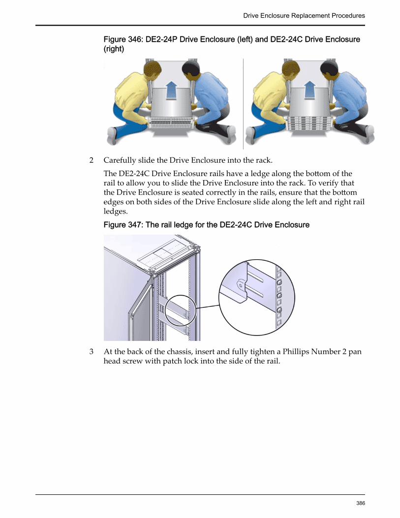
Figure 346: DE2-24P Drive Enclosure (left) and DE2-24C Drive Enclosure(right)
2 Carefully slide the Drive Enclosure into the rack.
The DE2-24C Drive Enclosure rails have a ledge along the bottom of therail to allow you to slide the Drive Enclosure into the rack. To verify thatthe Drive Enclosure is seated correctly in the rails, ensure that the bottomedges on both sides of the Drive Enclosure slide along the left and right railledges.
Figure 347: The rail ledge for the DE2-24C Drive Enclosure
3 At the back of the chassis, insert and fully tighten a Phillips Number 2 panhead screw with patch lock into the side of the rail.
Drive Enclosure Replacement Procedures
386

Figure 348: Phillips Number 2 pan head screw with patch lock
Legend 1 Phillips Number 2 pan head screw with patch lock
4 Remove the front-side caps on both sides of the Drive Enclosure and securea Phillips 13mm head hex flange screw.
Note: The front-side cap on the right side of the Drive Enclosure containsthe RFID tag, which uniquely identifies the Drive Enclosure. Take care notto mix up the right front-side caps among Drive Enclosures.
Figure 349: Left front-side cap and Phillips 13mm head hex flange screw
Legend 1 Phillips 13mm head hex flange screw 2 Left front-side cap
After you have secured the Drive Enclosure to the rails, attach the front-side caps to the Drive Enclosure.
5 Insert the I/O modules, the power cooling modules, and all of the drivesinto their corresponding slots in the chassis.
Drive Enclosure Replacement Procedures
387

Power On a Drive Enclosure1 Connect all of the data cables to the Drive Enclosure.
2 Connect one end of a power cord into each power cooling module.
3 Connect the other end of the power cords to the PDUs.
4 Turn the power switch to the On position.The power switch is located on the back of the Drive Enclosure.
5 Turn on the rack circuit breakers, if applicable.
It might take several minutes for a Drive Enclosure to power on.
After the Drive Enclosure powers on, make sure that the System PowerLED indicator on the front of the Drive Enclosure emits a steady green.Also, make sure that each power cooling module Status LED indicatoremits a steady green.
Accept the Drives for a Replacement Drive Enclosure1 Navigate to System > Alerts and Events > System Alerts.
2 Double-click the Foreign Disk Drive system alert.
3 Click Accept New Drives.
4 Click OK.
The system updates the statuses of each drive and automatically createsdrive groups. You must add all of the drive groups to the same StorageDomain from which the drive groups were removed.
Add Drive Groups to the Storage Domain1 Navigate to System > Storage Domains.
2 Select all of the new drive groups from the (unassigned) list, then selectActions > Add to Storage Domain.The GUI displays the Add to Storage Domain dialog.
3 From the Storage Domain list, select the name of the Storage Domain towhich the drive groups had been originally assigned.
4 Select Rebalance Volume Data.
5 From the Drive groups to be included list, verify that all of the drivegroups are selected.
6 Click OK.
Replace a Drive Enclosure (Data Inaccessible)Prerequisites: • Before handling a component, touch a grounded surface to
discharge any static electricity.
Drive Enclosure Replacement Procedures
388
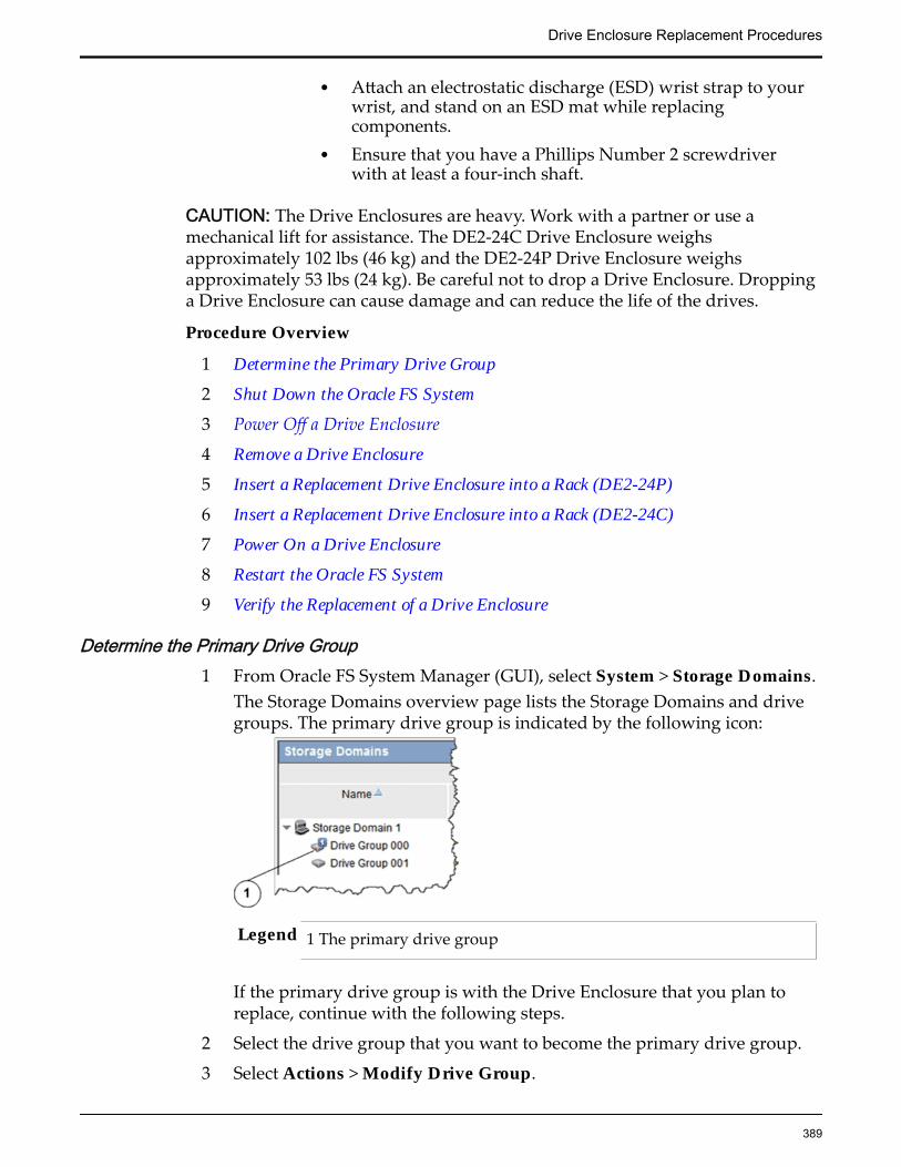
• Attach an electrostatic discharge (ESD) wrist strap to yourwrist, and stand on an ESD mat while replacingcomponents.
• Ensure that you have a Phillips Number 2 screwdriverwith at least a four-inch shaft.
CAUTION: The Drive Enclosures are heavy. Work with a partner or use amechanical lift for assistance. The DE2-24C Drive Enclosure weighsapproximately 102 lbs (46 kg) and the DE2-24P Drive Enclosure weighsapproximately 53 lbs (24 kg). Be careful not to drop a Drive Enclosure. Droppinga Drive Enclosure can cause damage and can reduce the life of the drives.
Procedure Overview
1 Determine the Primary Drive Group
2 Shut Down the Oracle FS System
3 Power Off a Drive Enclosure
4 Remove a Drive Enclosure
5 Insert a Replacement Drive Enclosure into a Rack (DE2-24P)
6 Insert a Replacement Drive Enclosure into a Rack (DE2-24C)
7 Power On a Drive Enclosure
8 Restart the Oracle FS System
9 Verify the Replacement of a Drive Enclosure
Determine the Primary Drive Group1 From Oracle FS System Manager (GUI), select System > Storage Domains.
The Storage Domains overview page lists the Storage Domains and drivegroups. The primary drive group is indicated by the following icon:
Legend 1 The primary drive group
If the primary drive group is with the Drive Enclosure that you plan toreplace, continue with the following steps.
2 Select the drive group that you want to become the primary drive group.
3 Select Actions > Modify Drive Group.
Drive Enclosure Replacement Procedures
389
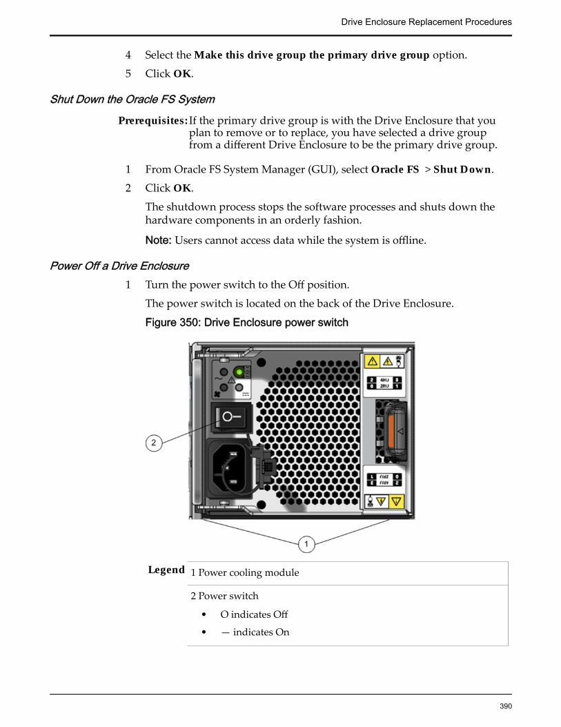
4 Select the Make this drive group the primary drive group option.
5 Click OK.
Shut Down the Oracle FS System
Prerequisites: If the primary drive group is with the Drive Enclosure that youplan to remove or to replace, you have selected a drive groupfrom a different Drive Enclosure to be the primary drive group.
1 From Oracle FS System Manager (GUI), select Oracle FS > Shut Down.
2 Click OK.
The shutdown process stops the software processes and shuts down thehardware components in an orderly fashion.
Note: Users cannot access data while the system is offline.
Power Off a Drive Enclosure1 Turn the power switch to the Off position.
The power switch is located on the back of the Drive Enclosure.
Figure 350: Drive Enclosure power switch
Legend 1 Power cooling module
2 Power switch
• O indicates Off
• — indicates On
Drive Enclosure Replacement Procedures
390

2 Disconnect the power cords from the PDUs and from the power coolingmodules on the Drive Enclosure.
3 Disconnect all data cables from the Drive Enclosure.
Important: Label the data cables so that you can easily identify the datacables and corresponding ports when reconnecting.
Remove a Drive Enclosure1 Remove the I/O modules, the power cooling modules, and all of the drives
from the failed chassis and place them on a statically-protected surface.
Removing these replaceable units helps reduce the weight of the DriveEnclosure and makes it easier to lift.
Note: Label each drive with its corresponding drive slot number. Use thisinformation to ensure that you insert the drives into the correct drive slotsof the replacement chassis.
2 Remove the screws that secure the back of the Drive Enclosure chassis tothe rails.
Figure 351: Location of the screw that secures the chassis to the rail
3 Remove the Phillips 13mm head hex flange screws from the front of theDrive Enclosure chassis.
To access the Phillips 13mm head hex flange screws, remove the front-sidecaps located on the left and right sides of the Drive Enclosure.
Note: The front-side cap on the right side of the Drive Enclosure containsthe Drive Enclosure RFID tag, which uniquely identifies the DriveEnclosure. Take care not to mix up the right front-side caps among DriveEnclosures.
Drive Enclosure Replacement Procedures
391

Figure 352: Left front-side cap and Phillips 13mm head hex flange screw
Legend 1 Phillips 13mm head hex flange screw 2 Left front-side cap
4 Slide the Drive Enclosure to the front of the rack.5 With the help of a partner or a mechanical lift, remove the Drive Enclosure
from the rack.
Figure 353: DE2-24P Drive Enclosure (left) and DE-24C Drive Enclosure(right)
Note: Make sure to set the Drive Enclosure on an ESD-qualified mat orsurface.
CAUTION: Do not use the power supply handles to lift the chassis. Usingthe power supply handles to lift the chassis can damage the power coolingmodules and disrupt electrical power to the Drive Enclosure.
Insert a Replacement Drive Enclosure into a Rack (DE2-24P)1 With the help of a partner or mechanical lift, carefully lift the Drive
Enclosure to the location of the prepared slot and rest the Drive Enclosureon the bottom ledge of the left and right rails.
CAUTION: The Drive Enclosures are heavy. Work with a partner or use amechanical lift for assistance. The DE2-24C Drive Enclosure weighsapproximately 102 lbs (46 kg) and the DE2-24P Drive Enclosure weighs
Drive Enclosure Replacement Procedures
392
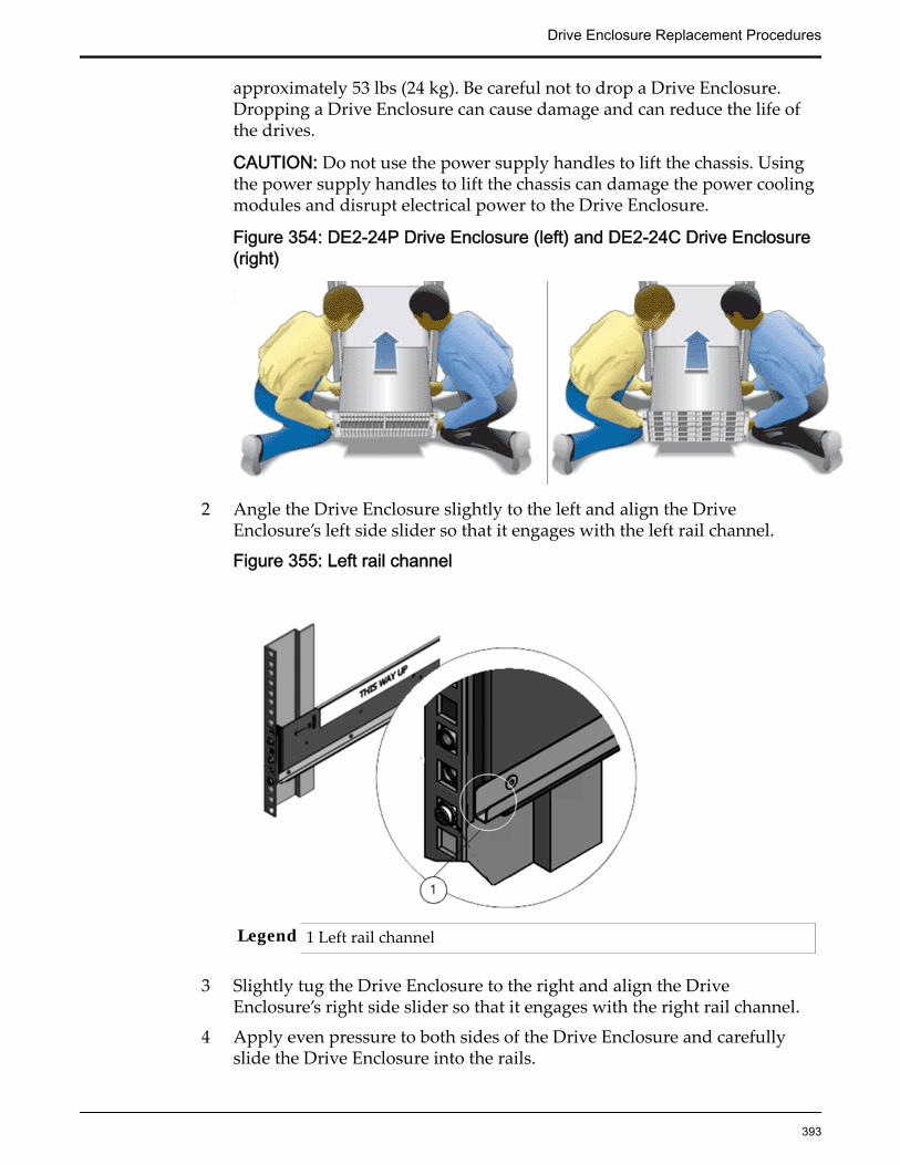
approximately 53 lbs (24 kg). Be careful not to drop a Drive Enclosure.Dropping a Drive Enclosure can cause damage and can reduce the life ofthe drives.
CAUTION: Do not use the power supply handles to lift the chassis. Usingthe power supply handles to lift the chassis can damage the power coolingmodules and disrupt electrical power to the Drive Enclosure.
Figure 354: DE2-24P Drive Enclosure (left) and DE2-24C Drive Enclosure(right)
2 Angle the Drive Enclosure slightly to the left and align the DriveEnclosure’s left side slider so that it engages with the left rail channel.
Figure 355: Left rail channel
Legend 1 Left rail channel
3 Slightly tug the Drive Enclosure to the right and align the DriveEnclosure’s right side slider so that it engages with the right rail channel.
4 Apply even pressure to both sides of the Drive Enclosure and carefullyslide the Drive Enclosure into the rails.
Drive Enclosure Replacement Procedures
393

Important: The Drive Enclosure must be fully seated in the rack. To verifythat the Drive Enclosure is fully seated, check for the following:
• Using a flashlight, visually check to see that the sliders on both sidesof the Drive Enclosure are in the rail channels on both sides of therack. If the Drive Enclosure side sliders are not in the rail channels,then the Drive Enclosure is not seated. You must reinsert the DriveEnclosure.
• Ensure that the Drive Enclosure slides smoothly into the rack andout of the rack. If the Drive Enclosure does not slide smoothly in andout of the rack, then the Drive Enclosure is not seated. You mustreinsert the Drive Enclosure.
• Ensure that the screw hole at the back of the Drive Enclosure alignswith the screw hole on the rail. Do not secure the screw, yet. If thescrew hole at the back of the Drive Enclosure does not align with thescrew hole on the rail, then the Drive Enclosure is not seated. Youmust reinsert the Drive Enclosure.
5 On both sides of the Drive Enclosure, insert a Phillips Number 2 pan headscrew with patch lock through the hole at the back of the Drive Enclosureand secure it into the screw hole on the rail.
Figure 356: Back of the Drive Enclosure and Rail secured
Legend 1 Phillips Number 2 pan head screwwith patch lock
2 Back of the DriveEnclosure
Drive Enclosure Replacement Procedures
394
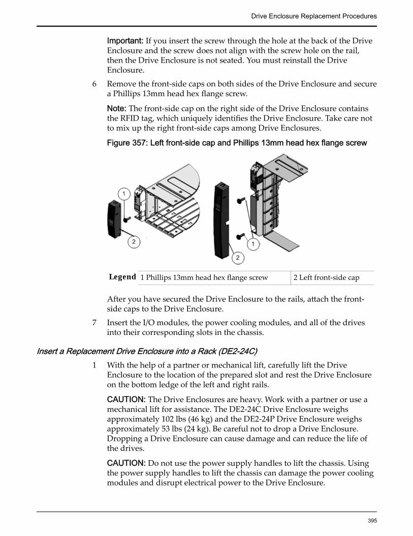
Important: If you insert the screw through the hole at the back of the DriveEnclosure and the screw does not align with the screw hole on the rail,then the Drive Enclosure is not seated. You must reinstall the DriveEnclosure.
6 Remove the front-side caps on both sides of the Drive Enclosure and securea Phillips 13mm head hex flange screw.
Note: The front-side cap on the right side of the Drive Enclosure containsthe RFID tag, which uniquely identifies the Drive Enclosure. Take care notto mix up the right front-side caps among Drive Enclosures.
Figure 357: Left front-side cap and Phillips 13mm head hex flange screw
Legend 1 Phillips 13mm head hex flange screw 2 Left front-side cap
After you have secured the Drive Enclosure to the rails, attach the front-side caps to the Drive Enclosure.
7 Insert the I/O modules, the power cooling modules, and all of the drivesinto their corresponding slots in the chassis.
Insert a Replacement Drive Enclosure into a Rack (DE2-24C)1 With the help of a partner or mechanical lift, carefully lift the Drive
Enclosure to the location of the prepared slot and rest the Drive Enclosureon the bottom ledge of the left and right rails.
CAUTION: The Drive Enclosures are heavy. Work with a partner or use amechanical lift for assistance. The DE2-24C Drive Enclosure weighsapproximately 102 lbs (46 kg) and the DE2-24P Drive Enclosure weighsapproximately 53 lbs (24 kg). Be careful not to drop a Drive Enclosure.Dropping a Drive Enclosure can cause damage and can reduce the life ofthe drives.
CAUTION: Do not use the power supply handles to lift the chassis. Usingthe power supply handles to lift the chassis can damage the power coolingmodules and disrupt electrical power to the Drive Enclosure.
Drive Enclosure Replacement Procedures
395

Figure 358: DE2-24P Drive Enclosure (left) and DE2-24C Drive Enclosure(right)
2 Carefully slide the Drive Enclosure into the rack.
The DE2-24C Drive Enclosure rails have a ledge along the bottom of therail to allow you to slide the Drive Enclosure into the rack. To verify thatthe Drive Enclosure is seated correctly in the rails, ensure that the bottomedges on both sides of the Drive Enclosure slide along the left and right railledges.
Figure 359: The rail ledge for the DE2-24C Drive Enclosure
3 At the back of the chassis, insert and fully tighten a Phillips Number 2 panhead screw with patch lock into the side of the rail.
Drive Enclosure Replacement Procedures
396

Figure 360: Phillips Number 2 pan head screw with patch lock
Legend 1 Phillips Number 2 pan head screw with patch lock
4 Remove the front-side caps on both sides of the Drive Enclosure and securea Phillips 13mm head hex flange screw.
Note: The front-side cap on the right side of the Drive Enclosure containsthe RFID tag, which uniquely identifies the Drive Enclosure. Take care notto mix up the right front-side caps among Drive Enclosures.
Figure 361: Left front-side cap and Phillips 13mm head hex flange screw
Legend 1 Phillips 13mm head hex flange screw 2 Left front-side cap
After you have secured the Drive Enclosure to the rails, attach the front-side caps to the Drive Enclosure.
5 Insert the I/O modules, the power cooling modules, and all of the drivesinto their corresponding slots in the chassis.
Drive Enclosure Replacement Procedures
397
Power On a Drive Enclosure1 Connect all of the data cables to the Drive Enclosure.
2 Connect one end of a power cord into each power cooling module.
3 Connect the other end of the power cords to the PDUs.
4 Turn the power switch to the On position.The power switch is located on the back of the Drive Enclosure.
5 Turn on the rack circuit breakers, if applicable.
It might take several minutes for a Drive Enclosure to power on.
After the Drive Enclosure powers on, make sure that the System PowerLED indicator on the front of the Drive Enclosure emits a steady green.Also, make sure that each power cooling module Status LED indicatoremits a steady green.
Restart the Oracle FS System1 From Oracle FS System Manager (GUI), select Oracle FS > Restart.
2 Click OK.
Verify the Replacement of a Drive Enclosure
1 From Oracle FS System Manager (GUI), navigate to System > Hardware >Drive Enclosures.
2 From the Drive Enclosures Overview page, monitor the status of the DriveEnclosure as it returns online.
A status of Normal requires no action.
Verify that the Drive Enclosure and the drive groups have a status ofNormal.
Drive Enclosure Replacement Procedures
398

CHAPTER 5
Pilot Replacement Procedures
Pilot OverviewThe Pilot is an out-of-band management controller that directs and manages allsystem activity.
Each Oracle FS System has one active Pilot and one standby Pilot.
The Pilot provides access to the following:
• All management functions for the Oracle FS System
• System monitoring, alerts, log collection, and automatic log transmission
• Management for restarting, replacing, updating, and recovering Controllerand Drive Enclosure resources
The following figure shows the front of the Pilot.
Figure 362: Pilot
Replace a Pilot BatteryThe lithium coin-cell battery in the Pilot maintains system time when the Pilot ispowered off and a time server is unavailable. The battery also powers the CMOSBIOS system settings of the Oracle FS System. Replace the battery if the Pilot failsto maintain proper time or the battery gets discharged due to wear and tear.
Prerequisites: • Before handling a component, touch a groundedsurface to discharge any static electricity.
399

• Attach an electrostatic discharge (ESD) wrist strap toyour wrist, and stand on an ESD mat while replacingcomponents.
• Ensure you have a screwdriver or any kind of sharppointed object.
Each Pilot has a battery located on the Pilot motherboard. Batteries are customerreplaceable units (CRUs) and are not hot-serviceable. Replacing the batteryrequires you to power down the Pilot. The following figure identifies the locationof the battery inside the Pilot motherboard.
Figure 363: Pilot battery
Legend 1 Pilot battery
2 Pilot motherboard
Note: The battery can be accessed only after removing the cover over the Pilotchassis.
Note: Ensure that all power is removed from the Pilot before removing orinstalling the battery. You must disconnect the power cords from the Pilot beforeperforming these procedures.
Procedure Overview
1 Prepare a Pilot for Component Replacement
2 Power Off the Pilot
3 Slide Pilot to Service Position
4 Open Pilot Fan Door
5 Open Pilot Top Cover
6 Remove a Battery
7 Insert a Battery
8 Close Pilot Top Cover
Pilot Replacement Procedures
400

9 Close Pilot Fan Door
10 Slide Pilot to Rack Position
11 Connect Power Cords On the Pilot
12 Verify Component Replacement on the Standby Pilot
13 Verify Component Replacement on the Active Pilot
Prepare a Pilot for Component Replacement1 Contact Oracle Customer Support prior to replacing a Pilot component.
Oracle Customer Support identifies the failed component on the Pilot foryou.
2 From Oracle FS System Manager (GUI), navigate to System > Hardware >Pilots and select the Pilot that contains the component that you want toreplace.
3 Select Actions > Repair Pilot.Guided Maintenance displays the list of Pilot components.
4 Based on the information from your Oracle Customer Supportrepresentative, select the correct component from the list.
5 Click Next.Guided Maintenance sends a request to flash the LEDs on the Pilot to helpyou locate the Pilot in the data center.
6 Click Next.
Guided Maintenance displays a link to Pilot Repair Procedures.
7 Click the Pilot Repair Procedures link to open and print the procedures.
8 Click Next.
• If you are replacing a component located on the active Pilot, GuidedMaintenance takes the active Pilot offline and fails over to thestandby Pilot. After the active Pilot is offline, the GUI closes. Youmay now safely disconnect the power cords.
• If you are replacing a component located on the standby Pilot,Guided Maintenance takes the standby Pilot offline. After thestandby Pilot is offline, you may safely disconnect the power cordsand data cables. When servicing the standby Pilot, failover is notrequired.
• If you are replacing a power supply, you are not required to bringthe Pilot offline. The power supplies are hot-serviceable. The powersupplies are the only Pilot components that do not require the Pilotto be brought offline. You can replace one power supply withoutbringing the Pilot offline, as long as the second power supplyremains online and operational.
Pilot Replacement Procedures
401
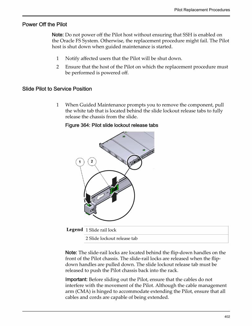
Power Off the Pilot
Note: Do not power off the Pilot host without ensuring that SSH is enabled onthe Oracle FS System. Otherwise, the replacement procedure might fail. The Pilothost is shut down when guided maintenance is started.
1 Notify affected users that the Pilot will be shut down.
2 Ensure that the host of the Pilot on which the replacement procedure mustbe performed is powered off.
Slide Pilot to Service Position
1 When Guided Maintenance prompts you to remove the component, pullthe white tab that is located behind the slide lockout release tabs to fullyrelease the chassis from the slide.
Figure 364: Pilot slide lockout release tabs
Legend 1 Slide rail lock
2 Slide lockout release tab
Note: The slide-rail locks are located behind the flip-down handles on thefront of the Pilot chassis. The slide-rail locks are released when the flip-down handles are pulled down. The slide lockout release tab must bereleased to push the Pilot chassis back into the rack.
Important: Before sliding out the Pilot, ensure that the cables do notinterfere with the movement of the Pilot. Although the cable managementarm (CMA) is hinged to accommodate extending the Pilot, ensure that allcables and cords are capable of being extended.
Pilot Replacement Procedures
402

2 Slide the Pilot chassis fully forward until the slide rails lock into position.
Figure 365: Pilot position during component replacement
Legend 1 Rack
2 Pilot chassis
3 Pilot rails
CAUTION: Deploy any rack anti-tilt mechanism before releasing therelease buttons and extending the Pilot.
Open Pilot Fan Door
Press the two fan door release tabs simultaneously forward and swing thePilot fan door to the open position.
Note: Servicing the Pilot fan modules and other components located in thefront of the Pilot, such as the front indication module (FIM) and the diskbackplanes, require that the fan door be opened. It is also easier to removethe Pilot’s top cover if you open the fan door first.
Pilot Replacement Procedures
403
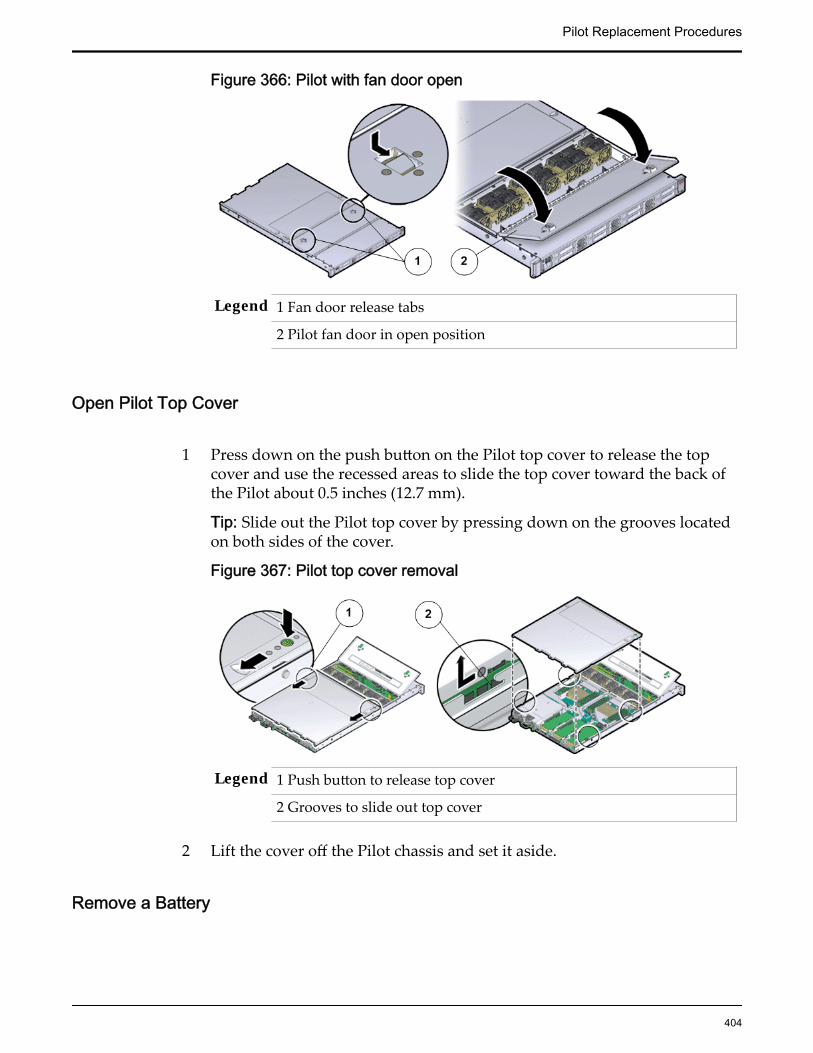
Figure 366: Pilot with fan door open
Legend 1 Fan door release tabs
2 Pilot fan door in open position
Open Pilot Top Cover
1 Press down on the push button on the Pilot top cover to release the topcover and use the recessed areas to slide the top cover toward the back ofthe Pilot about 0.5 inches (12.7 mm).
Tip: Slide out the Pilot top cover by pressing down on the grooves locatedon both sides of the cover.
Figure 367: Pilot top cover removal
Legend 1 Push button to release top cover
2 Grooves to slide out top cover
2 Lift the cover off the Pilot chassis and set it aside.
Remove a Battery
Pilot Replacement Procedures
404
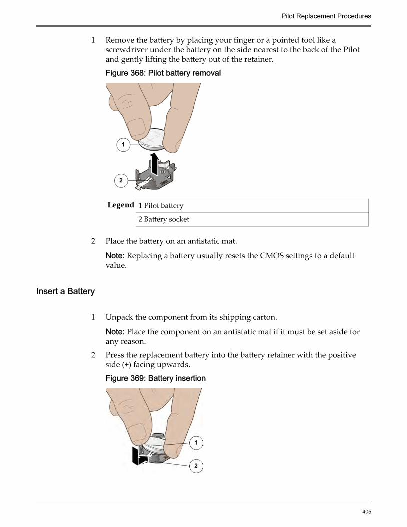
1 Remove the battery by placing your finger or a pointed tool like ascrewdriver under the battery on the side nearest to the back of the Pilotand gently lifting the battery out of the retainer.
Figure 368: Pilot battery removal
Legend 1 Pilot battery
2 Battery socket
2 Place the battery on an antistatic mat.
Note: Replacing a battery usually resets the CMOS settings to a defaultvalue.
Insert a Battery
1 Unpack the component from its shipping carton.
Note: Place the component on an antistatic mat if it must be set aside forany reason.
2 Press the replacement battery into the battery retainer with the positiveside (+) facing upwards.
Figure 369: Battery insertion
Pilot Replacement Procedures
405

Legend 1 Pilot battery
2 Battery socket
If the Pilot is configured to synchronize with a network time server usingthe Network Time Protocol (NTP), the Oracle ILOM clock is reset as soonas the Pilot is powered on and connected to the network. Otherwise,proceed to the next step.
3 If the Pilot is not configured to use NTP, reset the Oracle ILOM clock usingthe Oracle ILOM CLI or the web interface. You can also reprogram theBIOS Setup utility to reprogram the host clock.For instructions, on setting the Oracle ILOM clock, see the OracleIntegrated Lights Out Manager (ILOM) 3.1 Documentation Library.
Close Pilot Top Cover
1 Place the top cover of the Pilot onto the chassis.
Tip: Place the top cover down so that it hangs over the back of the Pilot byabout 13 mm (0.5 inches) [1] and the side latches align with the slots in thesides of the Pilot chassis.
Note: There are three latching tabs on the sides of the Pilot top cover, twoon the right side and one on the left side when viewing the Pilot from thefront. There is also a latch on the underside of the top cover in the front leftcorner near the release button.
2 Check both sides of the Pilot chassis to ensure that the four corners of thetop cover are fully down and flush with the chassis.
Note: If the cover corners are not flush with the Pilot chassis, slide thecover towards the back of the chassis until you can position the covercorrectly.
Note: If the top cover is not correctly positioned before attempting to slidethe cover forward, the internal latch that is on the underside of the covermight be damaged.
3 Gently slide the top cover along the grooves of the Pilot by pressing downon either side of the top cover until it locks into place and you hear anaudible click.
Pilot Replacement Procedures
406
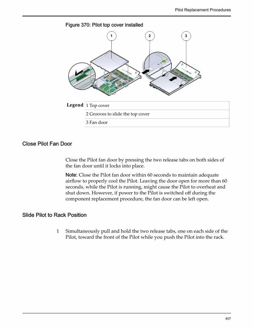
Figure 370: Pilot top cover installed
Legend 1 Top cover
2 Grooves to slide the top cover
3 Fan door
Close Pilot Fan Door
Close the Pilot fan door by pressing the two release tabs on both sides ofthe fan door until it locks into place.
Note: Close the Pilot fan door within 60 seconds to maintain adequateairflow to properly cool the Pilot. Leaving the door open for more than 60seconds, while the Pilot is running, might cause the Pilot to overheat andshut down. However, if power to the Pilot is switched off during thecomponent replacement procedure, the fan door can be left open.
Slide Pilot to Rack Position
1 Simultaneously pull and hold the two release tabs, one on each side of thePilot, toward the front of the Pilot while you push the Pilot into the rack.
Pilot Replacement Procedures
407
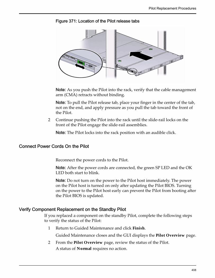
Figure 371: Location of the Pilot release tabs
Note: As you push the Pilot into the rack, verify that the cable managementarm (CMA) retracts without binding.
Note: To pull the Pilot release tab, place your finger in the center of the tab,not on the end, and apply pressure as you pull the tab toward the front ofthe Pilot.
2 Continue pushing the Pilot into the rack until the slide-rail locks on thefront of the Pilot engage the slide-rail assemblies.
Note: The Pilot locks into the rack position with an audible click.
Connect Power Cords On the Pilot
Reconnect the power cords to the Pilot.
Note: After the power cords are connected, the green SP LED and the OKLED both start to blink.
Note: Do not turn on the power to the Pilot host immediately. The poweron the Pilot host is turned on only after updating the Pilot BIOS. Turningon the power to the Pilot host early can prevent the Pilot from booting afterthe Pilot BIOS is updated.
Verify Component Replacement on the Standby PilotIf you replaced a component on the standby Pilot, complete the following stepsto verify the status of the Pilot:
1 Return to Guided Maintenance and click Finish.
Guided Maintenance closes and the GUI displays the Pilot Overview page.
2 From the Pilot Overview page, review the status of the Pilot.A status of Normal requires no action.
Pilot Replacement Procedures
408
Verify Component Replacement on the Active PilotIf you replaced a component on the active Pilot, complete the following steps toverify the status of the Pilot:
1 Restart Oracle FS System Manager (GUI).
2 Navigate to System > Hardware > Pilots.
The GUI displays the Pilot Overview page.
3 From the Pilot Overview page, review the status of the Pilot.A status of Normal requires no action.
Replace a Pilot SAS HBAA serial attached SCSI (SAS) host bus adapter (HBA) provides access to the SAShard disk drive (HDD) in the Pilot. A damaged SAS HBA can result in losingaccess to the SAS HDD to which the SAS HBA connects using the SAS cablebundle and must be replaced as soon as possible.
Prerequisites: • Before handling a component, touch a groundedsurface to discharge any static electricity.
• Attach an electrostatic discharge (ESD) wrist strap toyour wrist, and stand on an ESD mat while replacingcomponents.
• Ensure that you have a Phillips Number 2screwdriver with at least a four-inch shaft.
• Use only the filler panels provided with the Pilot tomaintain proper airflow and EMI conformance forempty slots inside the Pilot.
• Fail over the Pilot before replacing the componentusing Guided Maintenance
Note: The Pilot must be failed over to prevent dataloss or data corruption during the componentreplacement process.
Each Pilot supports a single 6 Gb/s SAS HBA on the PCIe slot of its riser. Toservice a SAS HBA, the PCIe risers inside the Pilot and the filler panels inside theriser must be removed. The SAS HBA is a customer replaceable unit (CRU) and isnot hot-serviceable. However, replacing a SAS HBA will require failing over alloperations to the other Pilot. The following figure shows the location of the SASHBA inside a riser board assembly.
Pilot Replacement Procedures
409

Figure 372: SAS HBA
Legend 1 Riser board assembly
2 SAS HBA
Note: The SAS HBA can be accessed only after removing the cover over the Pilotchassis.
Note: To replace a SAS HBA, you do not need to remove the Pilot from the rackbut extend it along the Pilot rails using the cable management arm (CMA).
Note: The riser that contains the failed SAS HBA must be removed beforeservicing the HBA.
Procedure Overview
1 Prepare a Pilot for Component Replacement
2 Power Off the Pilot
3 Slide Pilot to Service Position
4 Open Pilot Fan Door
5 Open Pilot Top Cover
6 Remove a SAS HBA
7 Insert a SAS HBA
8 Close Pilot Top Cover
9 Close Pilot Fan Door
10 Slide Pilot to Rack Position
11 Connect Power Cords On the Pilot
12 Verify Component Replacement on the Standby Pilot
13 Verify Component Replacement on the Active Pilot
Pilot Replacement Procedures
410
Prepare a Pilot for Component Replacement1 Contact Oracle Customer Support prior to replacing a Pilot component.
Oracle Customer Support identifies the failed component on the Pilot foryou.
2 From Oracle FS System Manager (GUI), navigate to System > Hardware >Pilots and select the Pilot that contains the component that you want toreplace.
3 Select Actions > Repair Pilot.Guided Maintenance displays the list of Pilot components.
4 Based on the information from your Oracle Customer Supportrepresentative, select the correct component from the list.
5 Click Next.Guided Maintenance sends a request to flash the LEDs on the Pilot to helpyou locate the Pilot in the data center.
6 Click Next.
Guided Maintenance displays a link to Pilot Repair Procedures.
7 Click the Pilot Repair Procedures link to open and print the procedures.
8 Click Next.
• If you are replacing a component located on the active Pilot, GuidedMaintenance takes the active Pilot offline and fails over to thestandby Pilot. After the active Pilot is offline, the GUI closes. Youmay now safely disconnect the power cords.
• If you are replacing a component located on the standby Pilot,Guided Maintenance takes the standby Pilot offline. After thestandby Pilot is offline, you may safely disconnect the power cordsand data cables. When servicing the standby Pilot, failover is notrequired.
• If you are replacing a power supply, you are not required to bringthe Pilot offline. The power supplies are hot-serviceable. The powersupplies are the only Pilot components that do not require the Pilotto be brought offline. You can replace one power supply withoutbringing the Pilot offline, as long as the second power supplyremains online and operational.
Power Off the Pilot
Note: Do not power off the Pilot host without ensuring that SSH is enabled onthe Oracle FS System. Otherwise, the replacement procedure might fail. The Pilothost is shut down when guided maintenance is started.
1 Notify affected users that the Pilot will be shut down.
Pilot Replacement Procedures
411
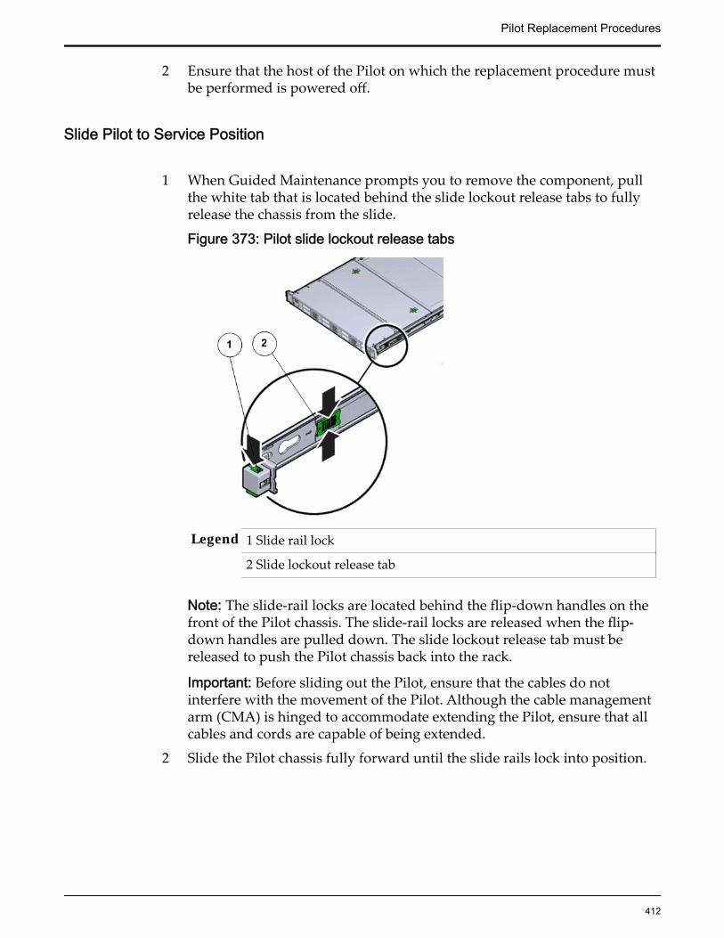
2 Ensure that the host of the Pilot on which the replacement procedure mustbe performed is powered off.
Slide Pilot to Service Position
1 When Guided Maintenance prompts you to remove the component, pullthe white tab that is located behind the slide lockout release tabs to fullyrelease the chassis from the slide.
Figure 373: Pilot slide lockout release tabs
Legend 1 Slide rail lock
2 Slide lockout release tab
Note: The slide-rail locks are located behind the flip-down handles on thefront of the Pilot chassis. The slide-rail locks are released when the flip-down handles are pulled down. The slide lockout release tab must bereleased to push the Pilot chassis back into the rack.
Important: Before sliding out the Pilot, ensure that the cables do notinterfere with the movement of the Pilot. Although the cable managementarm (CMA) is hinged to accommodate extending the Pilot, ensure that allcables and cords are capable of being extended.
2 Slide the Pilot chassis fully forward until the slide rails lock into position.
Pilot Replacement Procedures
412
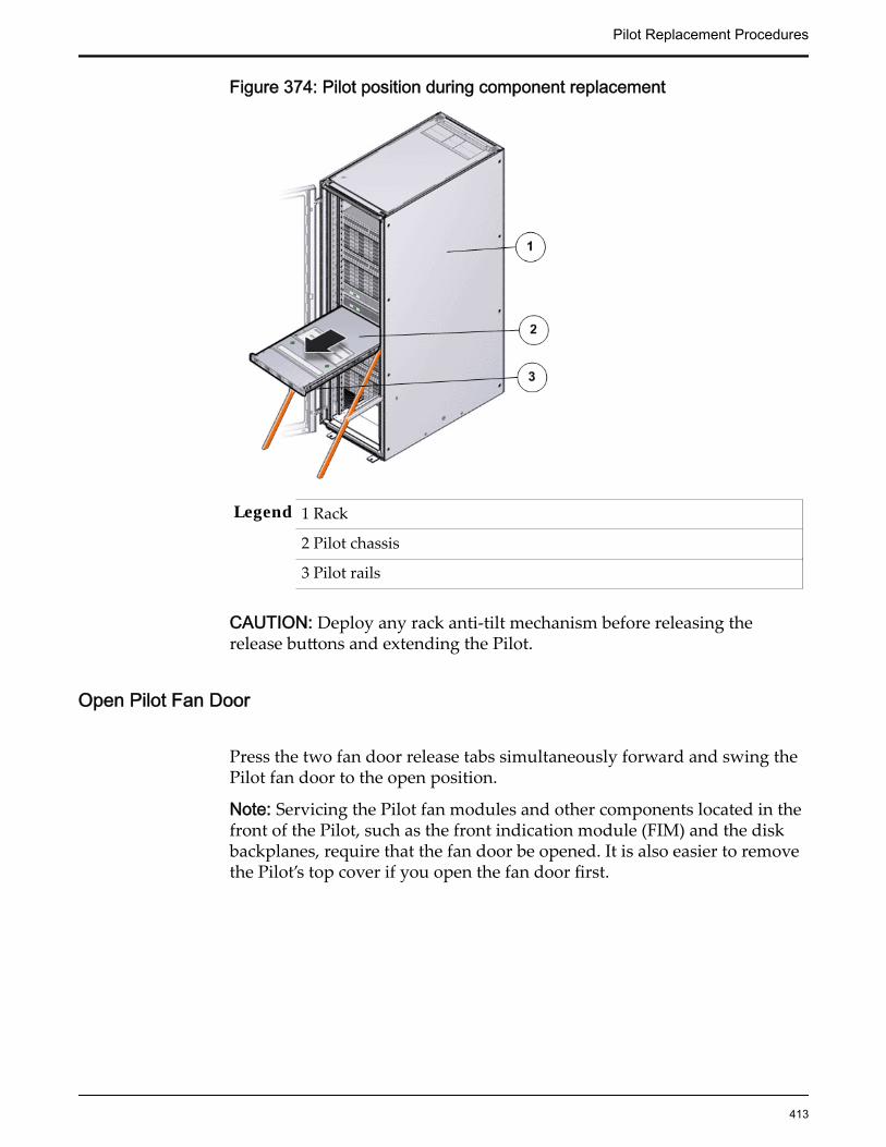
Figure 374: Pilot position during component replacement
Legend 1 Rack
2 Pilot chassis
3 Pilot rails
CAUTION: Deploy any rack anti-tilt mechanism before releasing therelease buttons and extending the Pilot.
Open Pilot Fan Door
Press the two fan door release tabs simultaneously forward and swing thePilot fan door to the open position.
Note: Servicing the Pilot fan modules and other components located in thefront of the Pilot, such as the front indication module (FIM) and the diskbackplanes, require that the fan door be opened. It is also easier to removethe Pilot’s top cover if you open the fan door first.
Pilot Replacement Procedures
413

Figure 375: Pilot with fan door open
Legend 1 Fan door release tabs
2 Pilot fan door in open position
Open Pilot Top Cover
1 Press down on the push button on the Pilot top cover to release the topcover and use the recessed areas to slide the top cover toward the back ofthe Pilot about 0.5 inches (12.7 mm).
Tip: Slide out the Pilot top cover by pressing down on the grooves locatedon both sides of the cover.
Figure 376: Pilot top cover removal
Legend 1 Push button to release top cover
2 Grooves to slide out top cover
2 Lift the cover off the Pilot chassis and set it aside.
Remove a SAS HBA
Identify the riser in which the failed SAS HBA is located.
Pilot Replacement Procedures
414
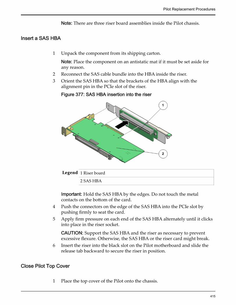
Note: There are three riser board assemblies inside the Pilot chassis.
Insert a SAS HBA
1 Unpack the component from its shipping carton.
Note: Place the component on an antistatic mat if it must be set aside forany reason.
2 Reconnect the SAS cable bundle into the HBA inside the riser.3 Orient the SAS HBA so that the brackets of the HBA align with the
alignment pin in the PCIe slot of the riser.
Figure 377: SAS HBA insertion into the riser
Legend 1 Riser board
2 SAS HBA
Important: Hold the SAS HBA by the edges. Do not touch the metalcontacts on the bottom of the card.
4 Push the connectors on the edge of the SAS HBA into the PCIe slot bypushing firmly to seat the card.
5 Apply firm pressure on each end of the SAS HBA alternately until it clicksinto place in the riser socket.
CAUTION: Support the SAS HBA and the riser as necessary to preventexcessive flexure. Otherwise, the SAS HBA or the riser card might break.
6 Insert the riser into the black slot on the Pilot motherboard and slide therelease tab backward to secure the riser in position.
Close Pilot Top Cover
1 Place the top cover of the Pilot onto the chassis.
Pilot Replacement Procedures
415

Tip: Place the top cover down so that it hangs over the back of the Pilot byabout 13 mm (0.5 inches) [1] and the side latches align with the slots in thesides of the Pilot chassis.
Note: There are three latching tabs on the sides of the Pilot top cover, twoon the right side and one on the left side when viewing the Pilot from thefront. There is also a latch on the underside of the top cover in the front leftcorner near the release button.
2 Check both sides of the Pilot chassis to ensure that the four corners of thetop cover are fully down and flush with the chassis.
Note: If the cover corners are not flush with the Pilot chassis, slide thecover towards the back of the chassis until you can position the covercorrectly.
Note: If the top cover is not correctly positioned before attempting to slidethe cover forward, the internal latch that is on the underside of the covermight be damaged.
3 Gently slide the top cover along the grooves of the Pilot by pressing downon either side of the top cover until it locks into place and you hear anaudible click.
Figure 378: Pilot top cover installed
Legend 1 Top cover
2 Grooves to slide the top cover
3 Fan door
Close Pilot Fan Door
Close the Pilot fan door by pressing the two release tabs on both sides ofthe fan door until it locks into place.
Pilot Replacement Procedures
416

Note: Close the Pilot fan door within 60 seconds to maintain adequateairflow to properly cool the Pilot. Leaving the door open for more than 60seconds, while the Pilot is running, might cause the Pilot to overheat andshut down. However, if power to the Pilot is switched off during thecomponent replacement procedure, the fan door can be left open.
Slide Pilot to Rack Position
1 Simultaneously pull and hold the two release tabs, one on each side of thePilot, toward the front of the Pilot while you push the Pilot into the rack.
Figure 379: Location of the Pilot release tabs
Note: As you push the Pilot into the rack, verify that the cable managementarm (CMA) retracts without binding.
Note: To pull the Pilot release tab, place your finger in the center of the tab,not on the end, and apply pressure as you pull the tab toward the front ofthe Pilot.
2 Continue pushing the Pilot into the rack until the slide-rail locks on thefront of the Pilot engage the slide-rail assemblies.
Note: The Pilot locks into the rack position with an audible click.
Connect Power Cords On the Pilot
Reconnect the power cords to the Pilot.
Note: After the power cords are connected, the green SP LED and the OKLED both start to blink.
Note: Do not turn on the power to the Pilot host immediately. The poweron the Pilot host is turned on only after updating the Pilot BIOS. Turningon the power to the Pilot host early can prevent the Pilot from booting afterthe Pilot BIOS is updated.
Pilot Replacement Procedures
417
Verify Component Replacement on the Standby PilotIf you replaced a component on the standby Pilot, complete the following stepsto verify the status of the Pilot:
1 Return to Guided Maintenance and click Finish.
Guided Maintenance closes and the GUI displays the Pilot Overview page.
2 From the Pilot Overview page, review the status of the Pilot.A status of Normal requires no action.
Verify Component Replacement on the Active PilotIf you replaced a component on the active Pilot, complete the following steps toverify the status of the Pilot:
1 Restart Oracle FS System Manager (GUI).
2 Navigate to System > Hardware > Pilots.
The GUI displays the Pilot Overview page.
3 From the Pilot Overview page, review the status of the Pilot.A status of Normal requires no action.
Replace a Pilot RiserRiser board assemblies include printed circuit boards and PCIe slots in whichHBAs can be inserted based on system type and configuration. A failed riserboard assembly can cause read and write errors because the HBAs will not beable to function properly. Replace a failed riser board as soon as possible.
Prerequisites: • Before handling a component, touch a groundedsurface to discharge any static electricity.
• Attach an electrostatic discharge (ESD) wrist strap toyour wrist, and stand on an ESD mat while replacingcomponents.
• Ensure that you have a Phillips Number 2screwdriver with at least a four-inch shaft.
• Fail over the Pilot before replacing the componentusing Guided Maintenance.
Note: The Pilot must be failed over to prevent dataloss or data corruption during the componentreplacement process.
Each Pilot contains three riser board assemblies (R1 to R3 – left to right) locatedside-by-side at the back of the Pilot next to the power supplies. Risers arecustomer replaceable units (CRUs). The SAS HBA is the only HBA that isinserted into the Pilot riser. Replacing a riser requires you to power down the
Pilot Replacement Procedures
418
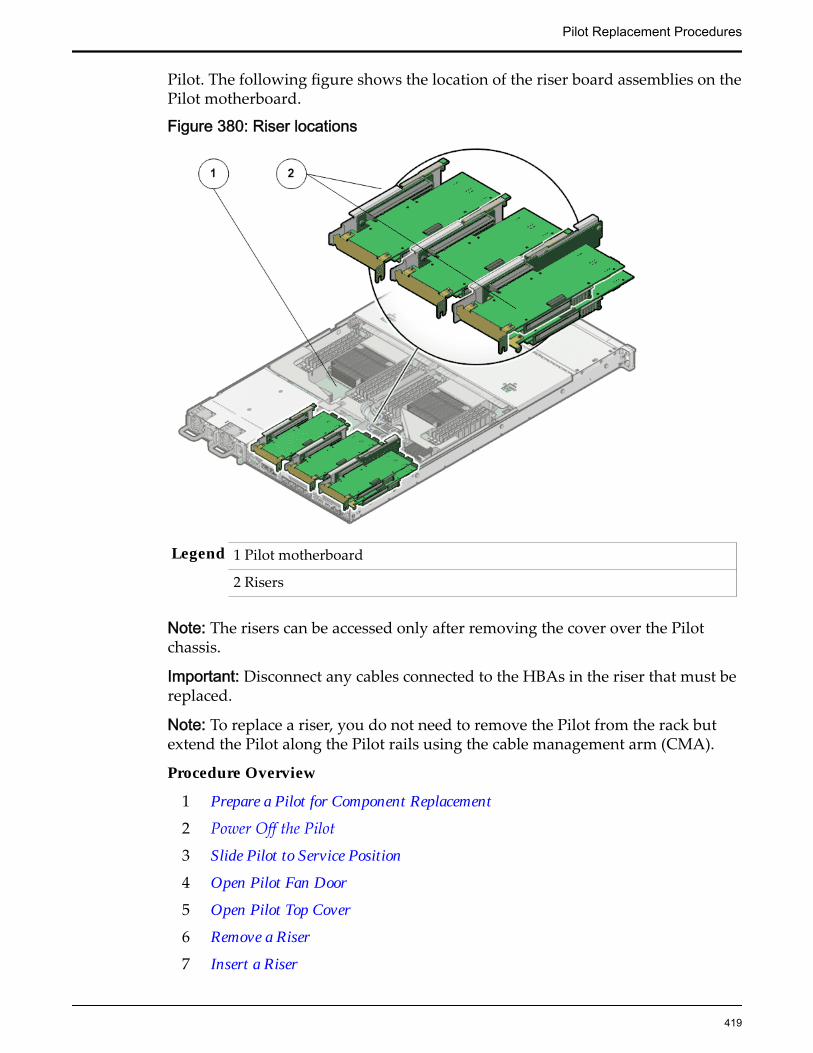
Pilot. The following figure shows the location of the riser board assemblies on thePilot motherboard.
Figure 380: Riser locations
Legend 1 Pilot motherboard
2 Risers
Note: The risers can be accessed only after removing the cover over the Pilotchassis.
Important: Disconnect any cables connected to the HBAs in the riser that must bereplaced.
Note: To replace a riser, you do not need to remove the Pilot from the rack butextend the Pilot along the Pilot rails using the cable management arm (CMA).
Procedure Overview
1 Prepare a Pilot for Component Replacement
2 Power Off the Pilot
3 Slide Pilot to Service Position
4 Open Pilot Fan Door
5 Open Pilot Top Cover
6 Remove a Riser
7 Insert a Riser
Pilot Replacement Procedures
419
8 Close Pilot Top Cover
9 Close Pilot Fan Door
10 Slide Pilot to Rack Position
11 Connect Power Cords On the Pilot
12 Verify Component Replacement on the Standby Pilot
13 Verify Component Replacement on the Active Pilot
Prepare a Pilot for Component Replacement1 Contact Oracle Customer Support prior to replacing a Pilot component.
Oracle Customer Support identifies the failed component on the Pilot foryou.
2 From Oracle FS System Manager (GUI), navigate to System > Hardware >Pilots and select the Pilot that contains the component that you want toreplace.
3 Select Actions > Repair Pilot.Guided Maintenance displays the list of Pilot components.
4 Based on the information from your Oracle Customer Supportrepresentative, select the correct component from the list.
5 Click Next.Guided Maintenance sends a request to flash the LEDs on the Pilot to helpyou locate the Pilot in the data center.
6 Click Next.
Guided Maintenance displays a link to Pilot Repair Procedures.7 Click the Pilot Repair Procedures link to open and print the procedures.8 Click Next.
• If you are replacing a component located on the active Pilot, GuidedMaintenance takes the active Pilot offline and fails over to thestandby Pilot. After the active Pilot is offline, the GUI closes. Youmay now safely disconnect the power cords.
• If you are replacing a component located on the standby Pilot,Guided Maintenance takes the standby Pilot offline. After thestandby Pilot is offline, you may safely disconnect the power cordsand data cables. When servicing the standby Pilot, failover is notrequired.
• If you are replacing a power supply, you are not required to bringthe Pilot offline. The power supplies are hot-serviceable. The powersupplies are the only Pilot components that do not require the Pilotto be brought offline. You can replace one power supply withoutbringing the Pilot offline, as long as the second power supplyremains online and operational.
Pilot Replacement Procedures
420

Power Off the Pilot
Note: Do not power off the Pilot host without ensuring that SSH is enabled onthe Oracle FS System. Otherwise, the replacement procedure might fail. The Pilothost is shut down when guided maintenance is started.
1 Notify affected users that the Pilot will be shut down.
2 Ensure that the host of the Pilot on which the replacement procedure mustbe performed is powered off.
Slide Pilot to Service Position
1 When Guided Maintenance prompts you to remove the component, pullthe white tab that is located behind the slide lockout release tabs to fullyrelease the chassis from the slide.
Figure 381: Pilot slide lockout release tabs
Legend 1 Slide rail lock
2 Slide lockout release tab
Note: The slide-rail locks are located behind the flip-down handles on thefront of the Pilot chassis. The slide-rail locks are released when the flip-down handles are pulled down. The slide lockout release tab must bereleased to push the Pilot chassis back into the rack.
Important: Before sliding out the Pilot, ensure that the cables do notinterfere with the movement of the Pilot. Although the cable managementarm (CMA) is hinged to accommodate extending the Pilot, ensure that allcables and cords are capable of being extended.
Pilot Replacement Procedures
421
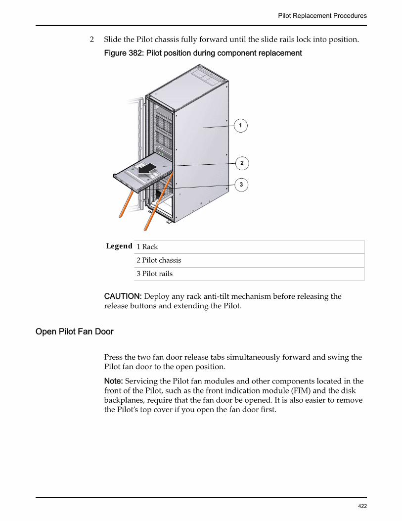
2 Slide the Pilot chassis fully forward until the slide rails lock into position.
Figure 382: Pilot position during component replacement
Legend 1 Rack
2 Pilot chassis
3 Pilot rails
CAUTION: Deploy any rack anti-tilt mechanism before releasing therelease buttons and extending the Pilot.
Open Pilot Fan Door
Press the two fan door release tabs simultaneously forward and swing thePilot fan door to the open position.
Note: Servicing the Pilot fan modules and other components located in thefront of the Pilot, such as the front indication module (FIM) and the diskbackplanes, require that the fan door be opened. It is also easier to removethe Pilot’s top cover if you open the fan door first.
Pilot Replacement Procedures
422

Figure 383: Pilot with fan door open
Legend 1 Fan door release tabs
2 Pilot fan door in open position
Open Pilot Top Cover
1 Press down on the push button on the Pilot top cover to release the topcover and use the recessed areas to slide the top cover toward the back ofthe Pilot about 0.5 inches (12.7 mm).
Tip: Slide out the Pilot top cover by pressing down on the grooves locatedon both sides of the cover.
Figure 384: Pilot top cover removal
Legend 1 Push button to release top cover
2 Grooves to slide out top cover
2 Lift the cover off the Pilot chassis and set it aside.
Remove a Riser
Pilot Replacement Procedures
423

1 Press on the release tab of the riser to release the riser from the Pilotmotherboard.
2 Carefully pull up the release tab on the riser to release the filler panel orHBA card (if any) and pull the riser straight up.
Figure 385: Riser board assembly removal
Legend 1 Release tab on the riser
2 Riser
3 HBA
4 Motherboard
Note: Remove any host bus adapter (HBA) cables or HBAs that are on thefailed riser assemblies using the appropriate procedure. Make a note of theriser slot in which the HBAs are installed and the SAS cables that areconnected to the HBAs.
3 Disconnect the SAS cable bundle that connects the SAS HBA and the Pilotdisk backplane and set aside.
Pilot Replacement Procedures
424
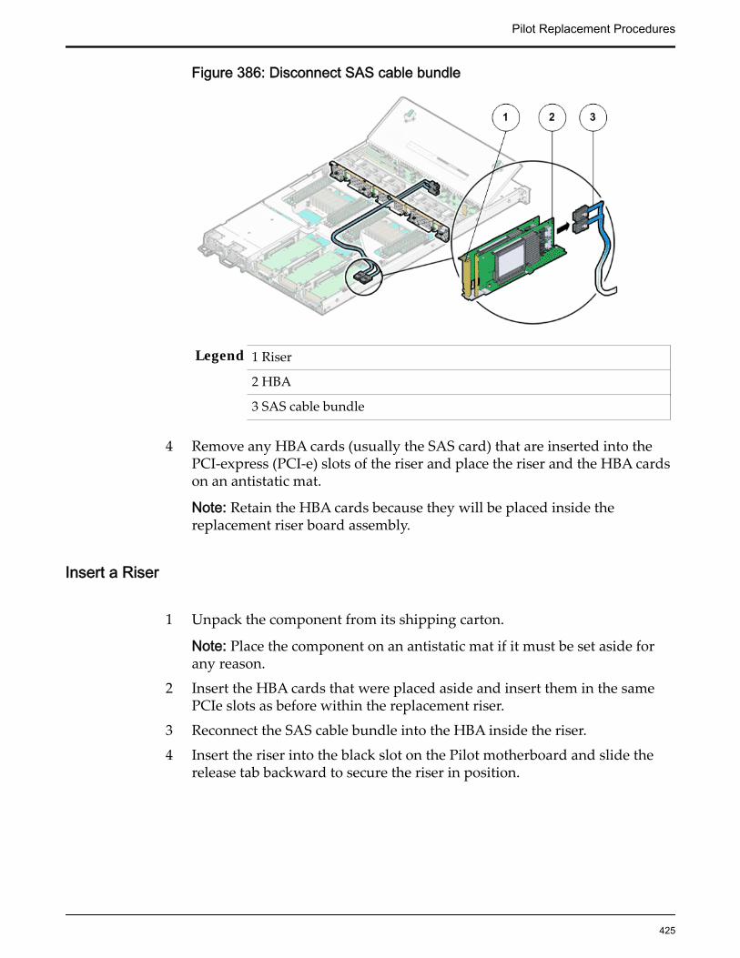
Figure 386: Disconnect SAS cable bundle
Legend 1 Riser
2 HBA
3 SAS cable bundle
4 Remove any HBA cards (usually the SAS card) that are inserted into thePCI-express (PCI-e) slots of the riser and place the riser and the HBA cardson an antistatic mat.
Note: Retain the HBA cards because they will be placed inside thereplacement riser board assembly.
Insert a Riser
1 Unpack the component from its shipping carton.
Note: Place the component on an antistatic mat if it must be set aside forany reason.
2 Insert the HBA cards that were placed aside and insert them in the samePCIe slots as before within the replacement riser.
3 Reconnect the SAS cable bundle into the HBA inside the riser.
4 Insert the riser into the black slot on the Pilot motherboard and slide therelease tab backward to secure the riser in position.
Pilot Replacement Procedures
425

Figure 387: Pilot riser insertion
Legend 1 Release tab
2 Riser
3 HBA
4Pilot motherboard
5 Insert the filler panels, if any, inside the riser.
Close Pilot Top Cover
1 Place the top cover of the Pilot onto the chassis.
Tip: Place the top cover down so that it hangs over the back of the Pilot byabout 13 mm (0.5 inches) [1] and the side latches align with the slots in thesides of the Pilot chassis.
Note: There are three latching tabs on the sides of the Pilot top cover, twoon the right side and one on the left side when viewing the Pilot from thefront. There is also a latch on the underside of the top cover in the front leftcorner near the release button.
2 Check both sides of the Pilot chassis to ensure that the four corners of thetop cover are fully down and flush with the chassis.
Note: If the cover corners are not flush with the Pilot chassis, slide thecover towards the back of the chassis until you can position the covercorrectly.
Pilot Replacement Procedures
426

Note: If the top cover is not correctly positioned before attempting to slidethe cover forward, the internal latch that is on the underside of the covermight be damaged.
3 Gently slide the top cover along the grooves of the Pilot by pressing downon either side of the top cover until it locks into place and you hear anaudible click.
Figure 388: Pilot top cover installed
Legend 1 Top cover
2 Grooves to slide the top cover
3 Fan door
Close Pilot Fan Door
Close the Pilot fan door by pressing the two release tabs on both sides ofthe fan door until it locks into place.
Note: Close the Pilot fan door within 60 seconds to maintain adequateairflow to properly cool the Pilot. Leaving the door open for more than 60seconds, while the Pilot is running, might cause the Pilot to overheat andshut down. However, if power to the Pilot is switched off during thecomponent replacement procedure, the fan door can be left open.
Slide Pilot to Rack Position
1 Simultaneously pull and hold the two release tabs, one on each side of thePilot, toward the front of the Pilot while you push the Pilot into the rack.
Pilot Replacement Procedures
427

Figure 389: Location of the Pilot release tabs
Note: As you push the Pilot into the rack, verify that the cable managementarm (CMA) retracts without binding.
Note: To pull the Pilot release tab, place your finger in the center of the tab,not on the end, and apply pressure as you pull the tab toward the front ofthe Pilot.
2 Continue pushing the Pilot into the rack until the slide-rail locks on thefront of the Pilot engage the slide-rail assemblies.
Note: The Pilot locks into the rack position with an audible click.
Connect Power Cords On the Pilot
Reconnect the power cords to the Pilot.
Note: After the power cords are connected, the green SP LED and the OKLED both start to blink.
Note: Do not turn on the power to the Pilot host immediately. The poweron the Pilot host is turned on only after updating the Pilot BIOS. Turningon the power to the Pilot host early can prevent the Pilot from booting afterthe Pilot BIOS is updated.
Verify Component Replacement on the Standby PilotIf you replaced a component on the standby Pilot, complete the following stepsto verify the status of the Pilot:
1 Return to Guided Maintenance and click Finish.
Guided Maintenance closes and the GUI displays the Pilot Overview page.
2 From the Pilot Overview page, review the status of the Pilot.A status of Normal requires no action.
Pilot Replacement Procedures
428

Verify Component Replacement on the Active PilotIf you replaced a component on the active Pilot, complete the following steps toverify the status of the Pilot:
1 Restart Oracle FS System Manager (GUI).
2 Navigate to System > Hardware > Pilots.
The GUI displays the Pilot Overview page.
3 From the Pilot Overview page, review the status of the Pilot.A status of Normal requires no action.
Replace a Pilot Power SupplyPower supplies, which exist in pairs, provide DC to all of the Pilot components. Ifone power supply fails, the other supply carries the full load. This situationcreates a risk of Pilot failure should the other power supply also fail.
Prerequisites: • Before handling a component, touch a groundedsurface to discharge any static electricity.
• Attach an electrostatic discharge (ESD) wrist strap toyour wrist, and stand on an ESD mat while replacingcomponents.
• Ensure that you have a similar replacement powersupply available before you start the replacementprocedure.
• Initiate Guided Maintenance only when you are ableto replace the power supplies immediately.
Each Pilot has a pair of power supplies that are located at the back of the Pilot.Power supplies are customer replaceable units (CRUs). Replacing a failed powersupply does not require you to bring the Pilot offline, provided that the otherpower supply is online and working. The following figure shows the location ofthe Pilot power supplies.
Figure 390: Location of the Pilot power supplies
Legend 1 Power supplies (PS-0 on left) and (PS-1 on right)
Pilot Replacement Procedures
429

Note: To replace a power supply, the left side of the CMA must be disengagedfrom the end of the slide before the power supply can be pulled out. Disengagingthe CMA reduces the risk of damaging the cables.
Important: Do not remove the failed power supply until you have a replacementpower supply to ensure proper airflow in the Pilot.
Procedure Overview
1 Prepare a Pilot for Component Replacement
2 Remove a Power Supply
3 Insert a Power Supply
4 Verify Power Supply Replacement on a Pilot
Prepare a Pilot for Component Replacement1 Contact Oracle Customer Support prior to replacing a Pilot component.
Oracle Customer Support identifies the failed component on the Pilot foryou.
2 From Oracle FS System Manager (GUI), navigate to System > Hardware >Pilots and select the Pilot that contains the component that you want toreplace.
3 Select Actions > Repair Pilot.Guided Maintenance displays the list of Pilot components.
4 Based on the information from your Oracle Customer Supportrepresentative, select the correct component from the list.
5 Click Next.Guided Maintenance sends a request to flash the LEDs on the Pilot to helpyou locate the Pilot in the data center.
6 Click Next.
Guided Maintenance displays a link to Pilot Repair Procedures.7 Click the Pilot Repair Procedures link to open and print the procedures.8 Click Next.
• If you are replacing a component located on the active Pilot, GuidedMaintenance takes the active Pilot offline and fails over to thestandby Pilot. After the active Pilot is offline, the GUI closes. Youmay now safely disconnect the power cords.
• If you are replacing a component located on the standby Pilot,Guided Maintenance takes the standby Pilot offline. After thestandby Pilot is offline, you may safely disconnect the power cordsand data cables. When servicing the standby Pilot, failover is notrequired.
• If you are replacing a power supply, you are not required to bringthe Pilot offline. The power supplies are hot-serviceable. The power
Pilot Replacement Procedures
430

supplies are the only Pilot components that do not require the Pilotto be brought offline. You can replace one power supply withoutbringing the Pilot offline, as long as the second power supplyremains online and operational.
Remove a Power Supply
1 From the back of the Pilot, remove the velcro that holds the power cordfrom the failed power supply.
Note: You might need to swing the cable management arm (CMA) out ofthe way to access the power supplies. If the CMA is still in the way, extendthe Pilot approximately 20 cm (8 inches) out of the front of the rack.
Note: The fans of a failed power supply may still be spinning when thesystem is powered on. You can remove a power supply while the fans arestill spinning.
2 Disconnect the power cord from the failed power supply.
3 While holding the power supply handle with one hand, use the other handto push the power supply latch to the left.
Figure 391: Power supply removal
Legend 1 Power supplies (PS0 and PS1)
2 Power supply handle
3 Power supply compartment
4 Pull the power supply out of the chassis and place the power supply on anantistatic mat.
CAUTION: Whenever you remove a power supply, you should replace itwith another power supply; otherwise, the Pilot might overheat due toimproper airflow.
Pilot Replacement Procedures
431
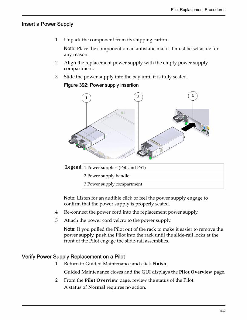
Insert a Power Supply
1 Unpack the component from its shipping carton.
Note: Place the component on an antistatic mat if it must be set aside forany reason.
2 Align the replacement power supply with the empty power supplycompartment.
3 Slide the power supply into the bay until it is fully seated.
Figure 392: Power supply insertion
Legend 1 Power supplies (PS0 and PS1)
2 Power supply handle
3 Power supply compartment
Note: Listen for an audible click or feel the power supply engage toconfirm that the power supply is properly seated.
4 Re-connect the power cord into the replacement power supply.
5 Attach the power cord velcro to the power supply.
Note: If you pulled the Pilot out of the rack to make it easier to remove thepower supply, push the Pilot into the rack until the slide-rail locks at thefront of the Pilot engage the slide-rail assemblies.
Verify Power Supply Replacement on a Pilot1 Return to Guided Maintenance and click Finish.
Guided Maintenance closes and the GUI displays the Pilot Overview page.
2 From the Pilot Overview page, review the status of the Pilot.A status of Normal requires no action.
Pilot Replacement Procedures
432

Replace a Pilot Fan ModuleIf a fan module fails, the Pilot internal temperature rises quickly. If thetemperature exceeds normal thresholds, the system issues critical alerts. Replacefan modules as soon as possible to prevent high-temperature buildup.
Prerequisites: • Before handling a component, touch a groundedsurface to discharge any static electricity.
• Attach an electrostatic discharge (ESD) wrist strap toyour wrist, and stand on an ESD mat while replacingcomponents.
• If you need to replace multiple fan module, replaceonly one fan module at a time and within fiveminutes.
• Initiate Guided Maintenance only when you are ableto replace the fan module immediately.
Each Pilot has four fan modules that are located side-by-side at the center insidethe Pilot chassis. A fan module is a customer replaceable unit (CRU) and is hot-serviceable. Replacing a fan module does not require you to bring the Pilotoffline. The following figure shows the location of the Pilot fan modules.
Figure 393: Fan module location
Legend 1 Fan module
2 Fan compartment
3 Fan door
4 Pilot
Note: The fan module can be accessed only after removing the cover over thePilot chassis.
Pilot Replacement Procedures
433

Note: To replace a fan module, you do not need to remove the Pilot from the rackbut extend it along the Pilot rails using the cable management arm (CMA).
Procedure Overview
1 Prepare a Pilot for Component Replacement
2 Slide Pilot to Service Position
3 Open Pilot Fan Door
4 Remove a Fan Module
5 Insert a Fan Module
6 Close Pilot Fan Door
7 Slide Pilot to Rack Position
8 Verify Component Replacement on the Standby Pilot
9 Verify Component Replacement on the Active Pilot
Prepare a Pilot for Component Replacement1 Contact Oracle Customer Support prior to replacing a Pilot component.
Oracle Customer Support identifies the failed component on the Pilot foryou.
2 From Oracle FS System Manager (GUI), navigate to System > Hardware >Pilots and select the Pilot that contains the component that you want toreplace.
3 Select Actions > Repair Pilot.Guided Maintenance displays the list of Pilot components.
4 Based on the information from your Oracle Customer Supportrepresentative, select the correct component from the list.
5 Click Next.Guided Maintenance sends a request to flash the LEDs on the Pilot to helpyou locate the Pilot in the data center.
6 Click Next.
Guided Maintenance displays a link to Pilot Repair Procedures.7 Click the Pilot Repair Procedures link to open and print the procedures.8 Click Next.
• If you are replacing a component located on the active Pilot, GuidedMaintenance takes the active Pilot offline and fails over to thestandby Pilot. After the active Pilot is offline, the GUI closes. Youmay now safely disconnect the power cords.
• If you are replacing a component located on the standby Pilot,Guided Maintenance takes the standby Pilot offline. After thestandby Pilot is offline, you may safely disconnect the power cords
Pilot Replacement Procedures
434

and data cables. When servicing the standby Pilot, failover is notrequired.
• If you are replacing a power supply, you are not required to bringthe Pilot offline. The power supplies are hot-serviceable. The powersupplies are the only Pilot components that do not require the Pilotto be brought offline. You can replace one power supply withoutbringing the Pilot offline, as long as the second power supplyremains online and operational.
Slide Pilot to Service Position
1 When Guided Maintenance prompts you to remove the component, pullthe white tab that is located behind the slide lockout release tabs to fullyrelease the chassis from the slide.
Figure 394: Pilot slide lockout release tabs
Legend 1 Slide rail lock
2 Slide lockout release tab
Note: The slide-rail locks are located behind the flip-down handles on thefront of the Pilot chassis. The slide-rail locks are released when the flip-down handles are pulled down. The slide lockout release tab must bereleased to push the Pilot chassis back into the rack.
Important: Before sliding out the Pilot, ensure that the cables do notinterfere with the movement of the Pilot. Although the cable managementarm (CMA) is hinged to accommodate extending the Pilot, ensure that allcables and cords are capable of being extended.
2 Slide the Pilot chassis fully forward until the slide rails lock into position.
Pilot Replacement Procedures
435

Figure 395: Pilot position during component replacement
Legend 1 Rack
2 Pilot chassis
3 Pilot rails
CAUTION: Deploy any rack anti-tilt mechanism before releasing therelease buttons and extending the Pilot.
Open Pilot Fan Door
Press the two fan door release tabs simultaneously forward and swing thePilot fan door to the open position.
Note: Servicing the Pilot fan modules and other components located in thefront of the Pilot, such as the front indication module (FIM) and the diskbackplanes, require that the fan door be opened. It is also easier to removethe Pilot’s top cover if you open the fan door first.
Pilot Replacement Procedures
436
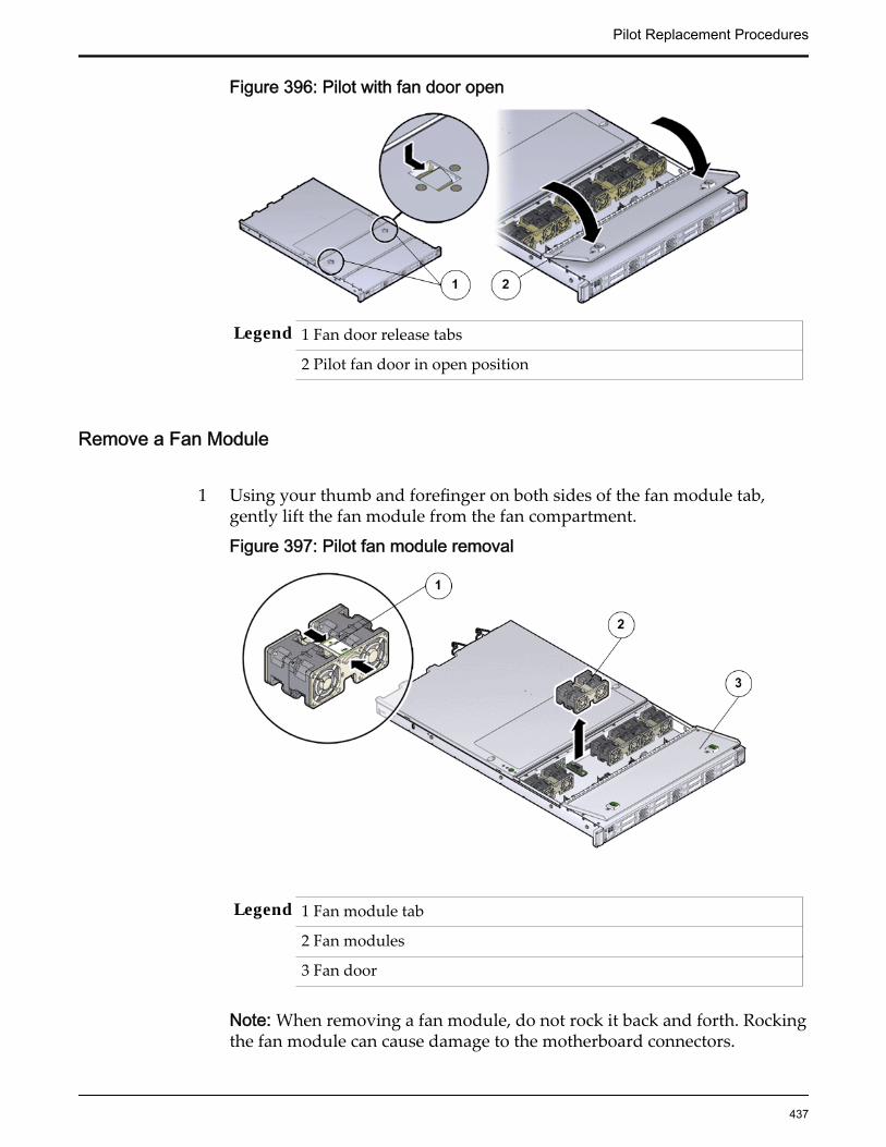
Figure 396: Pilot with fan door open
Legend 1 Fan door release tabs
2 Pilot fan door in open position
Remove a Fan Module
1 Using your thumb and forefinger on both sides of the fan module tab,gently lift the fan module from the fan compartment.
Figure 397: Pilot fan module removal
Legend 1 Fan module tab
2 Fan modules
3 Fan door
Note: When removing a fan module, do not rock it back and forth. Rockingthe fan module can cause damage to the motherboard connectors.
Pilot Replacement Procedures
437

2 Set the fan module aside on an antistatic mat.
Note: When replacing a fan module, do not service any other componentsunless the system is shut down and the power cords are removed.
Insert a Fan Module
1 Unpack the component from its shipping carton.
Note: Place the component on an antistatic mat if it must be set aside forany reason.
2 Grasp the fan module tabs and press the fan down firmly into the fanmodule compartment.
Figure 398: Fan module insertion
Legend 1 Fan module tab
2 Fan modules
3 Fan door
Note: Apply firm pressure to fully seat the fan module into the fancompartment. The fan modules are notched to ensure that they areinstalled in the correct orientation.
3 Press down on the fan module and apply firm pressure to fully seat the fanmodule.
Close Pilot Fan Door
Pilot Replacement Procedures
438
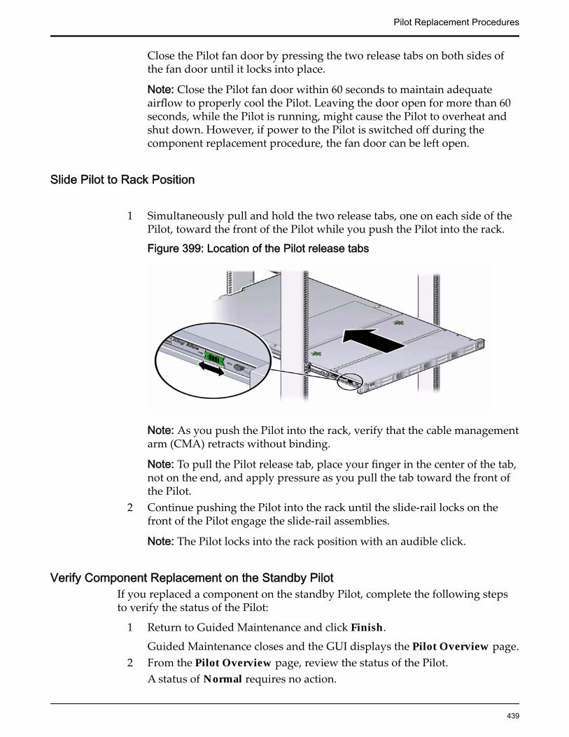
Close the Pilot fan door by pressing the two release tabs on both sides ofthe fan door until it locks into place.
Note: Close the Pilot fan door within 60 seconds to maintain adequateairflow to properly cool the Pilot. Leaving the door open for more than 60seconds, while the Pilot is running, might cause the Pilot to overheat andshut down. However, if power to the Pilot is switched off during thecomponent replacement procedure, the fan door can be left open.
Slide Pilot to Rack Position
1 Simultaneously pull and hold the two release tabs, one on each side of thePilot, toward the front of the Pilot while you push the Pilot into the rack.
Figure 399: Location of the Pilot release tabs
Note: As you push the Pilot into the rack, verify that the cable managementarm (CMA) retracts without binding.
Note: To pull the Pilot release tab, place your finger in the center of the tab,not on the end, and apply pressure as you pull the tab toward the front ofthe Pilot.
2 Continue pushing the Pilot into the rack until the slide-rail locks on thefront of the Pilot engage the slide-rail assemblies.
Note: The Pilot locks into the rack position with an audible click.
Verify Component Replacement on the Standby PilotIf you replaced a component on the standby Pilot, complete the following stepsto verify the status of the Pilot:
1 Return to Guided Maintenance and click Finish.
Guided Maintenance closes and the GUI displays the Pilot Overview page.2 From the Pilot Overview page, review the status of the Pilot.
A status of Normal requires no action.
Pilot Replacement Procedures
439
Verify Component Replacement on the Active PilotIf you replaced a component on the active Pilot, complete the following steps toverify the status of the Pilot:
1 Restart Oracle FS System Manager (GUI).
2 Navigate to System > Hardware > Pilots.
The GUI displays the Pilot Overview page.
3 From the Pilot Overview page, review the status of the Pilot.A status of Normal requires no action.
Replace a Pilot DIMMDual in-line memory modules (DIMMs) provide random access memory (RAM)for the central processing units (CPUs) in the Pilot. A failed DIMM would causethe Pilot to fail and must be replaced as soon as possible.
Prerequisites: • Before handling a component, touch a groundedsurface to discharge any static electricity.
• Attach an electrostatic discharge (ESD) wrist strap toyour wrist, and stand on an ESD mat while replacingcomponents.
• Ensure that all DIMM slots are filled with either fillerpanels or DIMMs to ensure proper airflow.
• Fail over the Pilot before replacing the componentusing Guided Maintenance.
Note: The Pilot must be failed over to prevent dataloss or data corruption during the componentreplacement process.
Each Pilot has two standard DIMMs with an 8 GB memory. DIMMs areconnected to the DIMM slots located on both sides of the central processing unit(CPUs) and heatsinks on the Pilot motherboard. DIMMs are customerreplaceable units (CRUs) but are not hot-swappable. Replacing a DIMM requiresyou to power down the Pilot. The following figure shows the location of theDIMMs on the Pilot motherboard and DIMM LEDs.
Pilot Replacement Procedures
440

Figure 400: Location of the DIMMs on the Pilot motherboard
Legend 1 DIMMs
2 Motherboard
3 DIMM LED
Note: The DIMMs can be accessed only after removing the cover over the Pilotchassis.
Note: To replace a DIMM, you do not need to remove the Pilot from the rack butextend it along the Pilot rails using the cable management arm (CMA).
Procedure Overview
1 Prepare a Pilot for Component Replacement
2 Power Off the Pilot
3 Slide Pilot to Service Position
4 Open Pilot Fan Door
5 Open Pilot Top Cover
6 Remove a Pilot DIMM
7 Insert a Pilot DIMM
8 Close Pilot Top Cover
9 Close Pilot Fan Door
10 Slide Pilot to Rack Position
11 Connect Power Cords On the Pilot
12 Verify Component Replacement on the Standby Pilot
13 Verify Component Replacement on the Active Pilot
Prepare a Pilot for Component Replacement1 Contact Oracle Customer Support prior to replacing a Pilot component.
Pilot Replacement Procedures
441
Oracle Customer Support identifies the failed component on the Pilot foryou.
2 From Oracle FS System Manager (GUI), navigate to System > Hardware >Pilots and select the Pilot that contains the component that you want toreplace.
3 Select Actions > Repair Pilot.Guided Maintenance displays the list of Pilot components.
4 Based on the information from your Oracle Customer Supportrepresentative, select the correct component from the list.
5 Click Next.Guided Maintenance sends a request to flash the LEDs on the Pilot to helpyou locate the Pilot in the data center.
6 Click Next.
Guided Maintenance displays a link to Pilot Repair Procedures.
7 Click the Pilot Repair Procedures link to open and print the procedures.
8 Click Next.
• If you are replacing a component located on the active Pilot, GuidedMaintenance takes the active Pilot offline and fails over to thestandby Pilot. After the active Pilot is offline, the GUI closes. Youmay now safely disconnect the power cords.
• If you are replacing a component located on the standby Pilot,Guided Maintenance takes the standby Pilot offline. After thestandby Pilot is offline, you may safely disconnect the power cordsand data cables. When servicing the standby Pilot, failover is notrequired.
• If you are replacing a power supply, you are not required to bringthe Pilot offline. The power supplies are hot-serviceable. The powersupplies are the only Pilot components that do not require the Pilotto be brought offline. You can replace one power supply withoutbringing the Pilot offline, as long as the second power supplyremains online and operational.
Power Off the Pilot
Note: Do not power off the Pilot host without ensuring that SSH is enabled onthe Oracle FS System. Otherwise, the replacement procedure might fail. The Pilothost is shut down when guided maintenance is started.
1 Notify affected users that the Pilot will be shut down.
2 Ensure that the host of the Pilot on which the replacement procedure mustbe performed is powered off.
Pilot Replacement Procedures
442
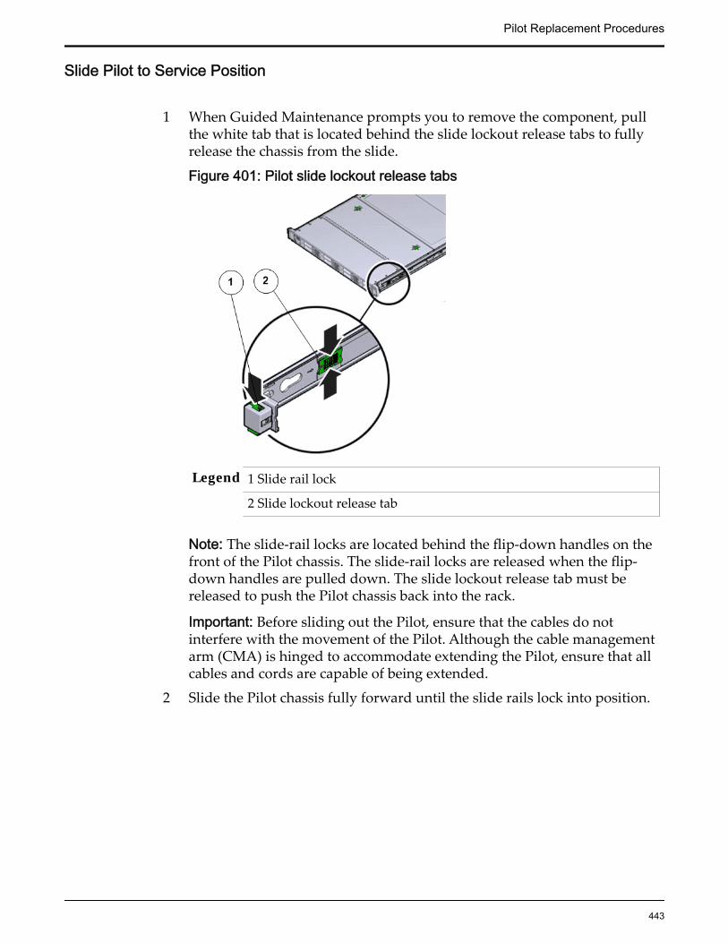
Slide Pilot to Service Position
1 When Guided Maintenance prompts you to remove the component, pullthe white tab that is located behind the slide lockout release tabs to fullyrelease the chassis from the slide.
Figure 401: Pilot slide lockout release tabs
Legend 1 Slide rail lock
2 Slide lockout release tab
Note: The slide-rail locks are located behind the flip-down handles on thefront of the Pilot chassis. The slide-rail locks are released when the flip-down handles are pulled down. The slide lockout release tab must bereleased to push the Pilot chassis back into the rack.
Important: Before sliding out the Pilot, ensure that the cables do notinterfere with the movement of the Pilot. Although the cable managementarm (CMA) is hinged to accommodate extending the Pilot, ensure that allcables and cords are capable of being extended.
2 Slide the Pilot chassis fully forward until the slide rails lock into position.
Pilot Replacement Procedures
443

Figure 402: Pilot position during component replacement
Legend 1 Rack
2 Pilot chassis
3 Pilot rails
CAUTION: Deploy any rack anti-tilt mechanism before releasing therelease buttons and extending the Pilot.
Open Pilot Fan Door
Press the two fan door release tabs simultaneously forward and swing thePilot fan door to the open position.
Note: Servicing the Pilot fan modules and other components located in thefront of the Pilot, such as the front indication module (FIM) and the diskbackplanes, require that the fan door be opened. It is also easier to removethe Pilot’s top cover if you open the fan door first.
Pilot Replacement Procedures
444

Figure 403: Pilot with fan door open
Legend 1 Fan door release tabs
2 Pilot fan door in open position
Open Pilot Top Cover
1 Press down on the push button on the Pilot top cover to release the topcover and use the recessed areas to slide the top cover toward the back ofthe Pilot about 0.5 inches (12.7 mm).
Tip: Slide out the Pilot top cover by pressing down on the grooves locatedon both sides of the cover.
Figure 404: Pilot top cover removal
Legend 1 Push button to release top cover
2 Grooves to slide out top cover
2 Lift the cover off the Pilot chassis and set it aside.
Remove a Pilot DIMM
1 Remove the DIMM by pressing down on the tabs on both sides of theDIMM to unlock it from the slot.
Pilot Replacement Procedures
445
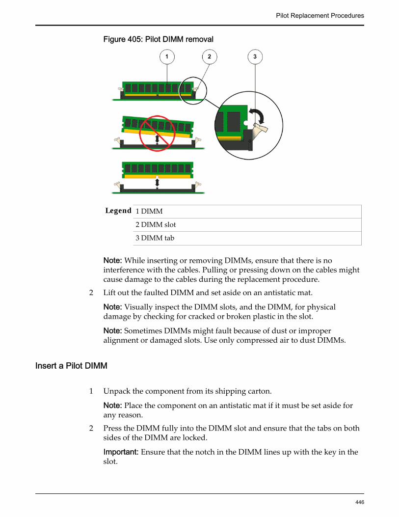
Figure 405: Pilot DIMM removal
Legend 1 DIMM
2 DIMM slot
3 DIMM tab
Note: While inserting or removing DIMMs, ensure that there is nointerference with the cables. Pulling or pressing down on the cables mightcause damage to the cables during the replacement procedure.
2 Lift out the faulted DIMM and set aside on an antistatic mat.
Note: Visually inspect the DIMM slots, and the DIMM, for physicaldamage by checking for cracked or broken plastic in the slot.
Note: Sometimes DIMMs might fault because of dust or improperalignment or damaged slots. Use only compressed air to dust DIMMs.
Insert a Pilot DIMM
1 Unpack the component from its shipping carton.
Note: Place the component on an antistatic mat if it must be set aside forany reason.
2 Press the DIMM fully into the DIMM slot and ensure that the tabs on bothsides of the DIMM are locked.
Important: Ensure that the notch in the DIMM lines up with the key in theslot.
Pilot Replacement Procedures
446
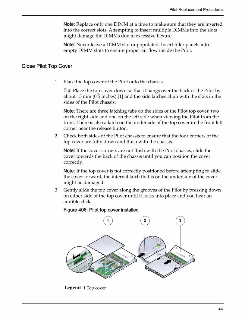
Note: Replace only one DIMM at a time to make sure that they are insertedinto the correct slots. Attempting to insert multiple DIMMs into the slotsmight damage the DIMMs due to excessive flexure.
Note: Never leave a DIMM slot unpopulated. Insert filler panels intoempty DIMM slots to ensure proper air flow inside the Pilot.
Close Pilot Top Cover
1 Place the top cover of the Pilot onto the chassis.
Tip: Place the top cover down so that it hangs over the back of the Pilot byabout 13 mm (0.5 inches) [1] and the side latches align with the slots in thesides of the Pilot chassis.
Note: There are three latching tabs on the sides of the Pilot top cover, twoon the right side and one on the left side when viewing the Pilot from thefront. There is also a latch on the underside of the top cover in the front leftcorner near the release button.
2 Check both sides of the Pilot chassis to ensure that the four corners of thetop cover are fully down and flush with the chassis.
Note: If the cover corners are not flush with the Pilot chassis, slide thecover towards the back of the chassis until you can position the covercorrectly.
Note: If the top cover is not correctly positioned before attempting to slidethe cover forward, the internal latch that is on the underside of the covermight be damaged.
3 Gently slide the top cover along the grooves of the Pilot by pressing downon either side of the top cover until it locks into place and you hear anaudible click.
Figure 406: Pilot top cover installed
Legend 1 Top cover
Pilot Replacement Procedures
447
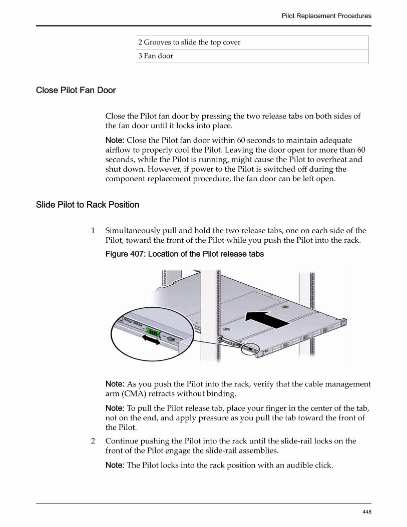
2 Grooves to slide the top cover
3 Fan door
Close Pilot Fan Door
Close the Pilot fan door by pressing the two release tabs on both sides ofthe fan door until it locks into place.
Note: Close the Pilot fan door within 60 seconds to maintain adequateairflow to properly cool the Pilot. Leaving the door open for more than 60seconds, while the Pilot is running, might cause the Pilot to overheat andshut down. However, if power to the Pilot is switched off during thecomponent replacement procedure, the fan door can be left open.
Slide Pilot to Rack Position
1 Simultaneously pull and hold the two release tabs, one on each side of thePilot, toward the front of the Pilot while you push the Pilot into the rack.
Figure 407: Location of the Pilot release tabs
Note: As you push the Pilot into the rack, verify that the cable managementarm (CMA) retracts without binding.
Note: To pull the Pilot release tab, place your finger in the center of the tab,not on the end, and apply pressure as you pull the tab toward the front ofthe Pilot.
2 Continue pushing the Pilot into the rack until the slide-rail locks on thefront of the Pilot engage the slide-rail assemblies.
Note: The Pilot locks into the rack position with an audible click.
Pilot Replacement Procedures
448
Connect Power Cords On the Pilot
Reconnect the power cords to the Pilot.
Note: After the power cords are connected, the green SP LED and the OKLED both start to blink.
Note: Do not turn on the power to the Pilot host immediately. The poweron the Pilot host is turned on only after updating the Pilot BIOS. Turningon the power to the Pilot host early can prevent the Pilot from booting afterthe Pilot BIOS is updated.
Verify Component Replacement on the Standby PilotIf you replaced a component on the standby Pilot, complete the following stepsto verify the status of the Pilot:
1 Return to Guided Maintenance and click Finish.
Guided Maintenance closes and the GUI displays the Pilot Overview page.
2 From the Pilot Overview page, review the status of the Pilot.A status of Normal requires no action.
Verify Component Replacement on the Active PilotIf you replaced a component on the active Pilot, complete the following steps toverify the status of the Pilot:
1 Restart Oracle FS System Manager (GUI).
2 Navigate to System > Hardware > Pilots.
The GUI displays the Pilot Overview page.
3 From the Pilot Overview page, review the status of the Pilot.A status of Normal requires no action.
Replace a Pilot ChassisIf an integrated riveted component of a Pilot chassis is damaged, the chassismust be replaced as soon as possible.
Prerequisites: • Ensure that you have a Phillips Number 2screwdriver with at least a four-inch shaft.
• Before handling a component, touch a groundedsurface to discharge any static electricity.
• Attach an electrostatic discharge (ESD) wrist strap toyour wrist, and stand on an ESD mat while replacingcomponents.
Pilot Replacement Procedures
449
• Ensure that there is a workbench available to placethe Pilot chassis once it is removed from the rack forservicing.
• Fail over the Pilot before replacing the componentusing Guided Maintenance.
Note: The Pilot must be failed over to prevent dataloss or data corruption during the componentreplacement process.
Each Oracle Flash Storage System has two Pilots installed in the rack. The Pilotchassis is a customer replaceable unit (CRU). Replacing a Pilot chassis requiresyou to bring the failed Pilot offline and fail over operations to the standby Pilotusing Guided Maintenance.
CAUTION: The Pilot weighs approximately 18.1 kilograms (39.9 pounds). Twopeople are required to carry the Pilot chassis and install it into the rack.
CAUTION: Deploy any rack anti-tilt mechanisms before installing the Pilot intothe rack.
Important: The replacement Pilot ships as a metal chassis without any pre-existing components inside it. Replacement of the Pilot chassis requiresassistance from Oracle Customer Support because it involves removing all FRUsand CRUs from the failed chassis and reinstalling them into the replacementchassis.
CAUTION: Ensure that all power is removed from the failed Pilot beforeremoving the Pilot chassis. You must disconnect the power cords beforeperforming this procedure.
Note: To replace a Pilot chassis, you must remove the failed Pilot from the rack.
Note: Using Guided Maintenance ensures that none of the re-used componentshave failed in case the replacement Pilot is re-using pre-existing components(CRUs and FRUs) from the failed Pilot.
Procedure Overview
1 Prepare a Pilot for Component Replacement
2 Power Off the Pilot
3 Disconnect Pilot Cabling
4 Slide Pilot to Service Position
5 Remove Pilot Chassis From Rack
6 Open Pilot Fan Door
7 Open Pilot Top Cover
8 Remove Components From the Pilot
9 Insert Components on the Pilot
Pilot Replacement Procedures
450
10 Close Pilot Top Cover
11 Close Pilot Fan Door
12 Insert the Pilot Onto the Rack
Prepare a Pilot for Component Replacement1 Contact Oracle Customer Support prior to replacing a Pilot component.
Oracle Customer Support identifies the failed component on the Pilot foryou.
2 From Oracle FS System Manager (GUI), navigate to System > Hardware >Pilots and select the Pilot that contains the component that you want toreplace.
3 Select Actions > Repair Pilot.Guided Maintenance displays the list of Pilot components.
4 Based on the information from your Oracle Customer Supportrepresentative, select the correct component from the list.
5 Click Next.Guided Maintenance sends a request to flash the LEDs on the Pilot to helpyou locate the Pilot in the data center.
6 Click Next.
Guided Maintenance displays a link to Pilot Repair Procedures.
7 Click the Pilot Repair Procedures link to open and print the procedures.
8 Click Next.
• If you are replacing a component located on the active Pilot, GuidedMaintenance takes the active Pilot offline and fails over to thestandby Pilot. After the active Pilot is offline, the GUI closes. Youmay now safely disconnect the power cords.
• If you are replacing a component located on the standby Pilot,Guided Maintenance takes the standby Pilot offline. After thestandby Pilot is offline, you may safely disconnect the power cordsand data cables. When servicing the standby Pilot, failover is notrequired.
• If you are replacing a power supply, you are not required to bringthe Pilot offline. The power supplies are hot-serviceable. The powersupplies are the only Pilot components that do not require the Pilotto be brought offline. You can replace one power supply withoutbringing the Pilot offline, as long as the second power supplyremains online and operational.
Pilot Replacement Procedures
451

Power Off the Pilot
Note: Do not power off the Pilot host without ensuring that SSH is enabled onthe Oracle FS System. Otherwise, the replacement procedure might fail. The Pilothost is shut down when guided maintenance is started.
1 Notify affected users that the Pilot will be shut down.
2 Ensure that the host of the Pilot on which the replacement procedure mustbe performed is powered off.
Disconnect Pilot Cabling
1 Disconnect all power and data cables from the Pilot.These include:
• Ethernet cables connected to the network ports
• Rollover cable connected to the serial port
• Power cables connected to the power supplies of the Pilot
Note: Oracle Customer Support recommends labeling all cables connectedto the Pilot so that they can be re-connected accurately to the Pilot after thereplacement procedure is complete.
Important: Ensure that the Pilot host is powered off completely beforeremoving the power cords.
CAUTION: When you press the power button to enter standby powermode, power is still directed to the power supply fans in the Pilot. Tocompletely power off the Pilot, you must disconnect the power cords fromthe back of the power supplies.
2 Disconnect the cable management arm (CMA) by pulling the release tabson the left side until the CMA detaches from the chassis.
Note: Do not disconnect the cables attached to the CMA.
Pilot Replacement Procedures
452
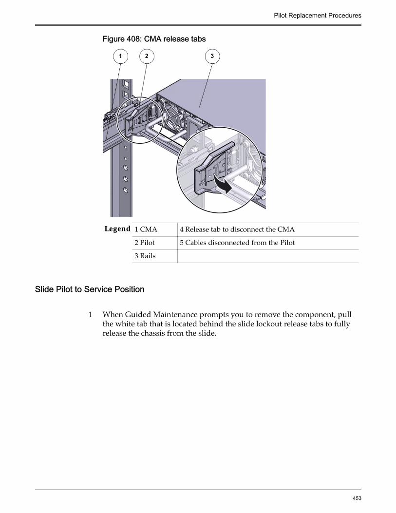
Figure 408: CMA release tabs
Legend 1 CMA 4 Release tab to disconnect the CMA
2 Pilot 5 Cables disconnected from the Pilot
3 Rails
Slide Pilot to Service Position
1 When Guided Maintenance prompts you to remove the component, pullthe white tab that is located behind the slide lockout release tabs to fullyrelease the chassis from the slide.
Pilot Replacement Procedures
453

Figure 409: Pilot slide lockout release tabs
Legend 1 Slide rail lock
2 Slide lockout release tab
Note: The slide-rail locks are located behind the flip-down handles on thefront of the Pilot chassis. The slide-rail locks are released when the flip-down handles are pulled down. The slide lockout release tab must bereleased to push the Pilot chassis back into the rack.
Important: Before sliding out the Pilot, ensure that the cables do notinterfere with the movement of the Pilot. Although the cable managementarm (CMA) is hinged to accommodate extending the Pilot, ensure that allcables and cords are capable of being extended.
2 Slide the Pilot chassis fully forward until the slide rails lock into position.
Pilot Replacement Procedures
454

Figure 410: Pilot position during component replacement
Legend 1 Rack
2 Pilot chassis
3 Pilot rails
CAUTION: Deploy any rack anti-tilt mechanism before releasing therelease buttons and extending the Pilot.
Remove Pilot Chassis From Rack
1 From the front of the Pilot, pull the slide-rail release tabs toward the frontof the Pilot and pull the Pilot out of the rack until it is free of the rack rails.
Note: A slide-rail release tab is located on each slide-rail. To pull the slide-rail release tab, place your finger in the center of the tab, not on the end,and apply pressure as you pull the tab toward the front of the Pilot.
2 With the help of a partner or a mechanical lift, place the Pilot on anantistatic surface or ESD qualified mat or workbench.
CAUTION: Deploy any rack anti-tilt mechanisms before installing the Pilotinto the rack.
CAUTION: The Pilot weighs approximately 39.9 pounds (18.1 kilograms).Two people are required to dismount and carry the chassis.
Pilot Replacement Procedures
455
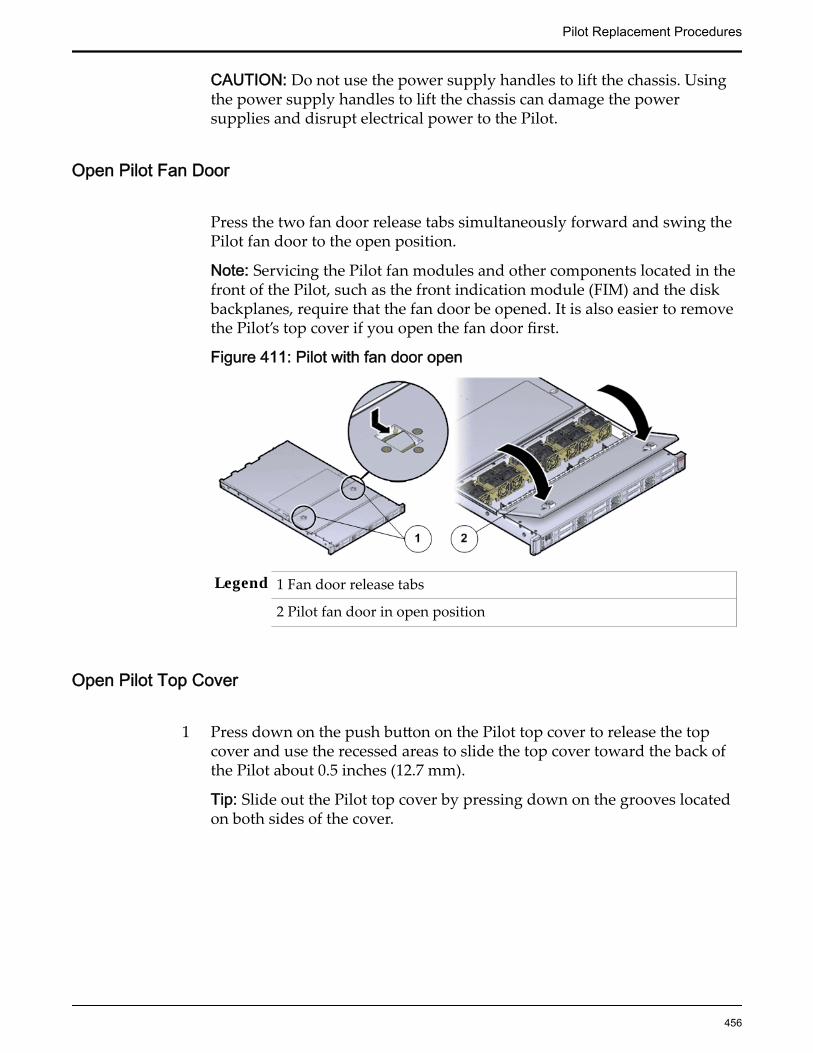
CAUTION: Do not use the power supply handles to lift the chassis. Usingthe power supply handles to lift the chassis can damage the powersupplies and disrupt electrical power to the Pilot.
Open Pilot Fan Door
Press the two fan door release tabs simultaneously forward and swing thePilot fan door to the open position.
Note: Servicing the Pilot fan modules and other components located in thefront of the Pilot, such as the front indication module (FIM) and the diskbackplanes, require that the fan door be opened. It is also easier to removethe Pilot’s top cover if you open the fan door first.
Figure 411: Pilot with fan door open
Legend 1 Fan door release tabs
2 Pilot fan door in open position
Open Pilot Top Cover
1 Press down on the push button on the Pilot top cover to release the topcover and use the recessed areas to slide the top cover toward the back ofthe Pilot about 0.5 inches (12.7 mm).
Tip: Slide out the Pilot top cover by pressing down on the grooves locatedon both sides of the cover.
Pilot Replacement Procedures
456
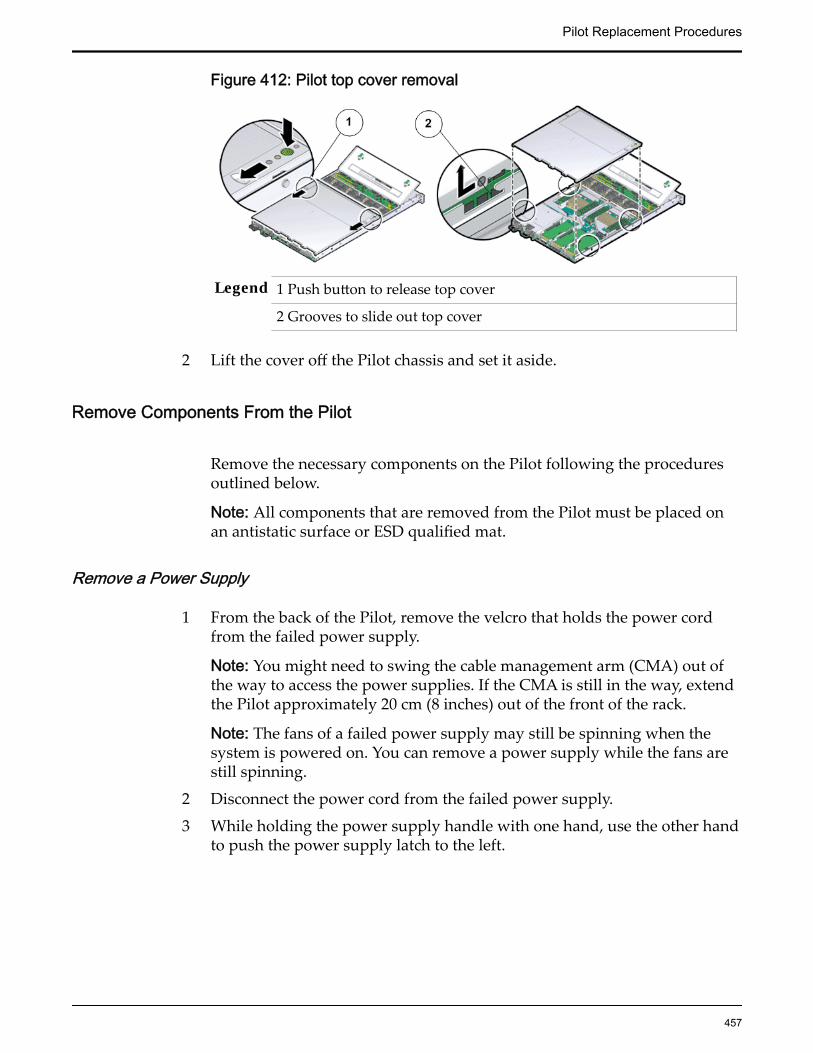
Figure 412: Pilot top cover removal
Legend 1 Push button to release top cover
2 Grooves to slide out top cover
2 Lift the cover off the Pilot chassis and set it aside.
Remove Components From the Pilot
Remove the necessary components on the Pilot following the proceduresoutlined below.
Note: All components that are removed from the Pilot must be placed onan antistatic surface or ESD qualified mat.
Remove a Power Supply
1 From the back of the Pilot, remove the velcro that holds the power cordfrom the failed power supply.
Note: You might need to swing the cable management arm (CMA) out ofthe way to access the power supplies. If the CMA is still in the way, extendthe Pilot approximately 20 cm (8 inches) out of the front of the rack.
Note: The fans of a failed power supply may still be spinning when thesystem is powered on. You can remove a power supply while the fans arestill spinning.
2 Disconnect the power cord from the failed power supply.
3 While holding the power supply handle with one hand, use the other handto push the power supply latch to the left.
Pilot Replacement Procedures
457

Figure 413: Power supply removal
Legend 1 Power supplies (PS0 and PS1)
2 Power supply handle
3 Power supply compartment
4 Pull the power supply out of the chassis and place the power supply on anantistatic mat.
CAUTION: Whenever you remove a power supply, you should replace itwith another power supply; otherwise, the Pilot might overheat due toimproper airflow.
Remove a Fan Module
1 Using your thumb and forefinger on both sides of the fan module tab,gently lift the fan module from the fan compartment.
Pilot Replacement Procedures
458

Figure 414: Pilot fan module removal
Legend 1 Fan module tab
2 Fan modules
3 Fan door
Note: When removing a fan module, do not rock it back and forth. Rockingthe fan module can cause damage to the motherboard connectors.
2 Set the fan module aside on an antistatic mat.
Note: When replacing a fan module, do not service any other componentsunless the system is shut down and the power cords are removed.
Remove the Fan Compartment
1 Lift the fan compartment straight up and out of the Pilot chassis.
Note: All fan modules must be removed from the fan compartment beforeremoving the fan compartment.
2 Set the component aside.
Remove a Pilot DIMM
1 Remove the DIMM by pressing down on the tabs on both sides of theDIMM to unlock it from the slot.
Pilot Replacement Procedures
459

Figure 415: Pilot DIMM removal
Legend 1 DIMM
2 DIMM slot
3 DIMM tab
Note: While inserting or removing DIMMs, ensure that there is nointerference with the cables. Pulling or pressing down on the cables mightcause damage to the cables during the replacement procedure.
2 Lift out the faulted DIMM and set aside on an antistatic mat.
Note: Visually inspect the DIMM slots, and the DIMM, for physicaldamage by checking for cracked or broken plastic in the slot.
Note: Sometimes DIMMs might fault because of dust or improperalignment or damaged slots. Use only compressed air to dust DIMMs.
Remove a Heat Sink
1 Loosen the four Phillips screws on the four sides of the heat sink in adiagonal pattern using a Phillips Number 2 screwdriver.
The four Phillips screws on the four sides of the heat sink secure the heatsink to the Pilot chassis.
Pilot Replacement Procedures
460

Figure 416: Loosen four screws to remove heat sink
Legend 1 Heat sink
2 Phillips screws that secure the heat sink
2 Lift up the failed heat sink and set aside the failed heat sink on an antistaticmat.
Note: Visually inspect the failed heat sink to verify if the thermal greasehas dried out. After cleaning the heat sink with an alcohol pad, applythermal grease to the heat sink, if necessary.
Remove a Pilot CPU
1 Press gently on the lever at the side of the CPU socket to disengage theCPU socket.
Figure 417: CPU socket disengaged
Legend 1 CPU socket lever
2 CPU socket
3 CPU
This exposes the CPU inside the CPU socket.
Pilot Replacement Procedures
461
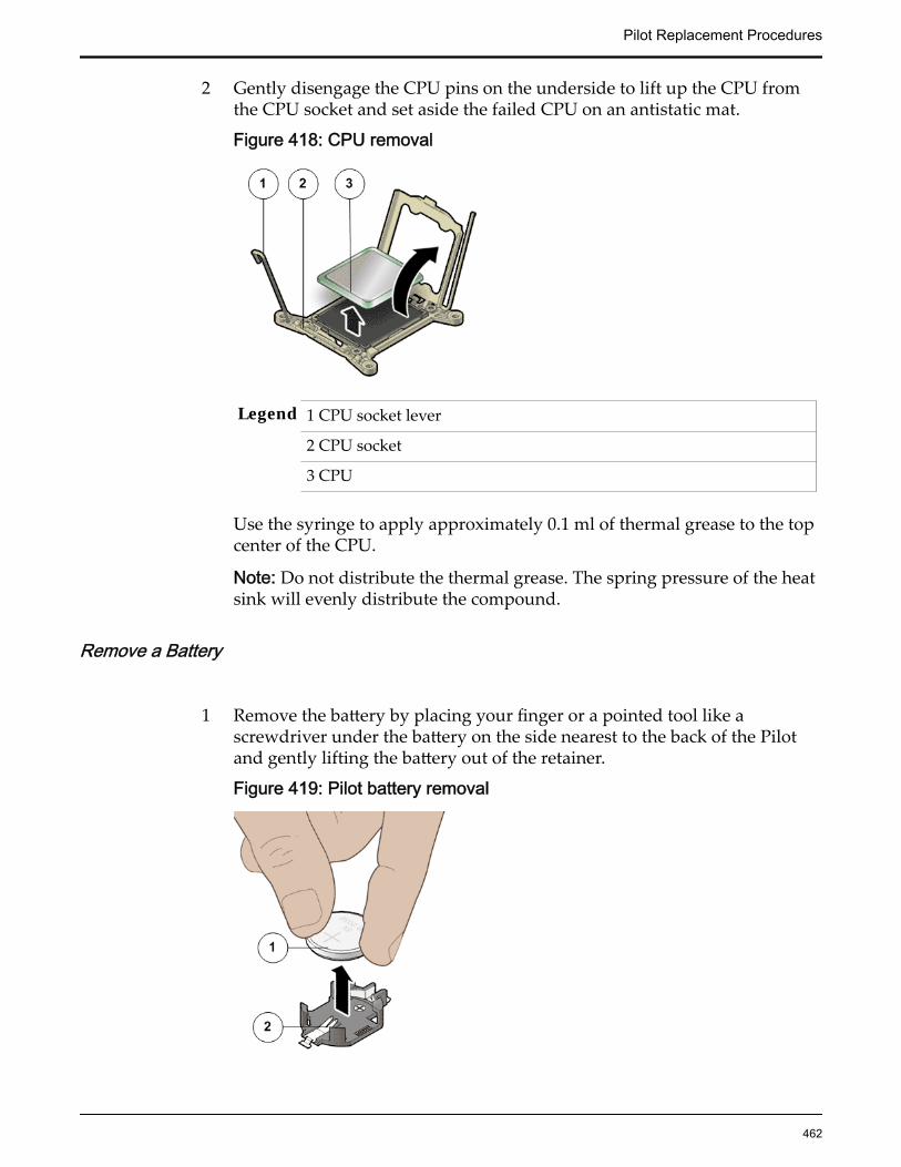
2 Gently disengage the CPU pins on the underside to lift up the CPU fromthe CPU socket and set aside the failed CPU on an antistatic mat.
Figure 418: CPU removal
Legend 1 CPU socket lever
2 CPU socket
3 CPU
Use the syringe to apply approximately 0.1 ml of thermal grease to the topcenter of the CPU.
Note: Do not distribute the thermal grease. The spring pressure of the heatsink will evenly distribute the compound.
Remove a Battery
1 Remove the battery by placing your finger or a pointed tool like ascrewdriver under the battery on the side nearest to the back of the Pilotand gently lifting the battery out of the retainer.
Figure 419: Pilot battery removal
Pilot Replacement Procedures
462

Legend 1 Pilot battery
2 Battery socket
2 Place the battery on an antistatic mat.
Note: Replacing a battery usually resets the CMOS settings to a defaultvalue.
Remove a Riser
1 Press on the release tab of the riser to release the riser from the Pilotmotherboard.
2 Carefully pull up the release tab on the riser to release the filler panel orHBA card (if any) and pull the riser straight up.
Figure 420: Riser board assembly removal
Legend 1 Release tab on the riser
2 Riser
3 HBA
4 Motherboard
Note: Remove any host bus adapter (HBA) cables or HBAs that are on thefailed riser assemblies using the appropriate procedure. Make a note of theriser slot in which the HBAs are installed and the SAS cables that areconnected to the HBAs.
Pilot Replacement Procedures
463

3 Disconnect the SAS cable bundle that connects the SAS HBA and the Pilotdisk backplane and set aside.
Figure 421: Disconnect SAS cable bundle
Legend 1 Riser
2 HBA
3 SAS cable bundle
4 Remove any HBA cards (usually the SAS card) that are inserted into thePCI-express (PCI-e) slots of the riser and place the riser and the HBA cardson an antistatic mat.
Note: Retain the HBA cards because they will be placed inside thereplacement riser board assembly.
Remove a SAS HBA
Identify the riser in which the failed SAS HBA is located.
Note: There are three riser board assemblies inside the Pilot chassis.
Remove a SAS HDD
1 On the Pilot with the failed SAS HDD, press the drive carrier latch todisengage the SAS HDD.
Pilot Replacement Procedures
464
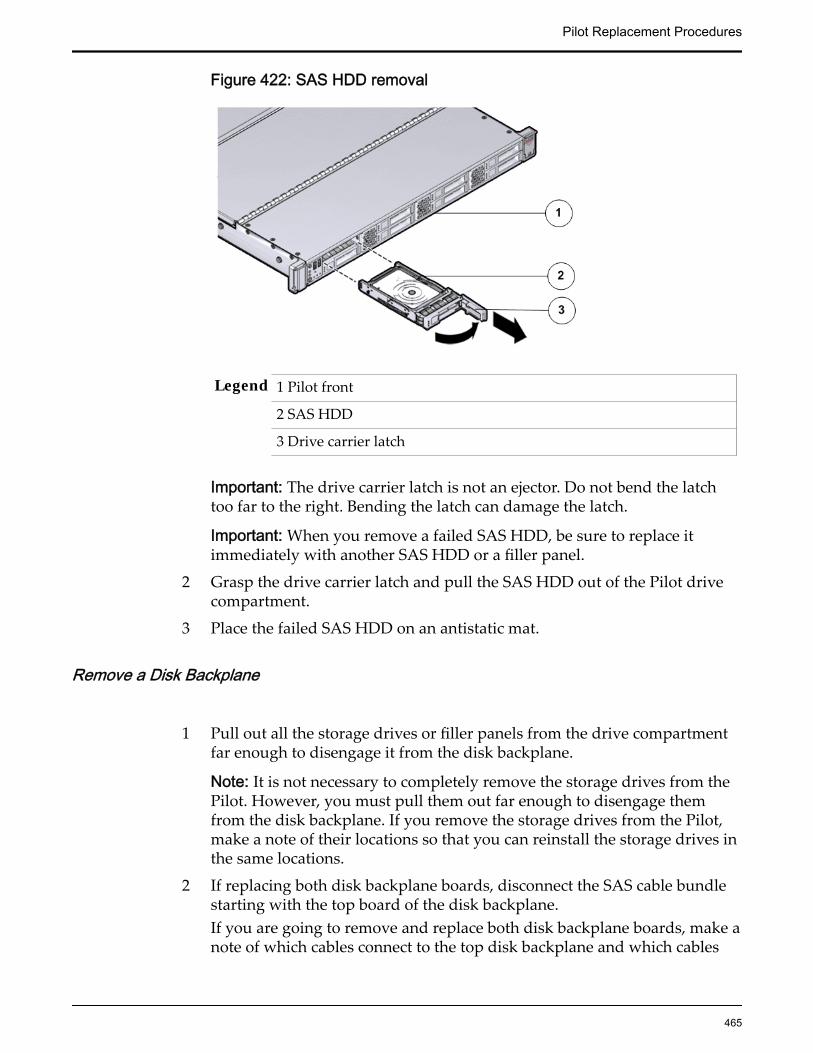
Figure 422: SAS HDD removal
Legend 1 Pilot front
2 SAS HDD
3 Drive carrier latch
Important: The drive carrier latch is not an ejector. Do not bend the latchtoo far to the right. Bending the latch can damage the latch.
Important: When you remove a failed SAS HDD, be sure to replace itimmediately with another SAS HDD or a filler panel.
2 Grasp the drive carrier latch and pull the SAS HDD out of the Pilot drivecompartment.
3 Place the failed SAS HDD on an antistatic mat.
Remove a Disk Backplane
1 Pull out all the storage drives or filler panels from the drive compartmentfar enough to disengage it from the disk backplane.
Note: It is not necessary to completely remove the storage drives from thePilot. However, you must pull them out far enough to disengage themfrom the disk backplane. If you remove the storage drives from the Pilot,make a note of their locations so that you can reinstall the storage drives inthe same locations.
2 If replacing both disk backplane boards, disconnect the SAS cable bundlestarting with the top board of the disk backplane.If you are going to remove and replace both disk backplane boards, make anote of which cables connect to the top disk backplane and which cables
Pilot Replacement Procedures
465

connect to the bottom disk backplane. Do this before disconnecting anybackplane cables.
Figure 423: Disk backplane cables disconnected
Legend 1 Disk backplane power cable
2 LED cable
3 SAS cable bundle
3 Disconnect the disk backplane LED cable (1U system controller cable) andthe disk backplane power cord from the disk backplane.
4 Using your thumb and fingers, loosen the two captive thumb screws thatsecure the disk backplane to the Pilot chassis.
Pilot Replacement Procedures
466
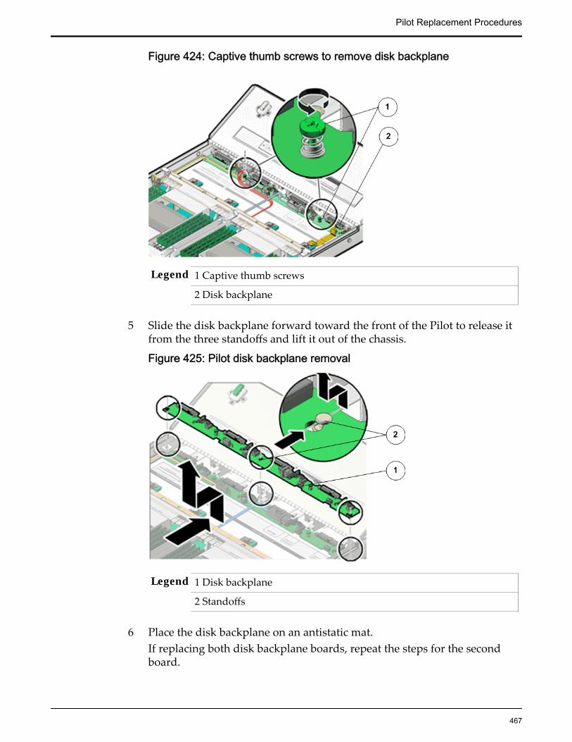
Figure 424: Captive thumb screws to remove disk backplane
Legend 1 Captive thumb screws
2 Disk backplane
5 Slide the disk backplane forward toward the front of the Pilot to release itfrom the three standoffs and lift it out of the chassis.
Figure 425: Pilot disk backplane removal
Legend 1 Disk backplane
2 Standoffs
6 Place the disk backplane on an antistatic mat.If replacing both disk backplane boards, repeat the steps for the secondboard.
Pilot Replacement Procedures
467
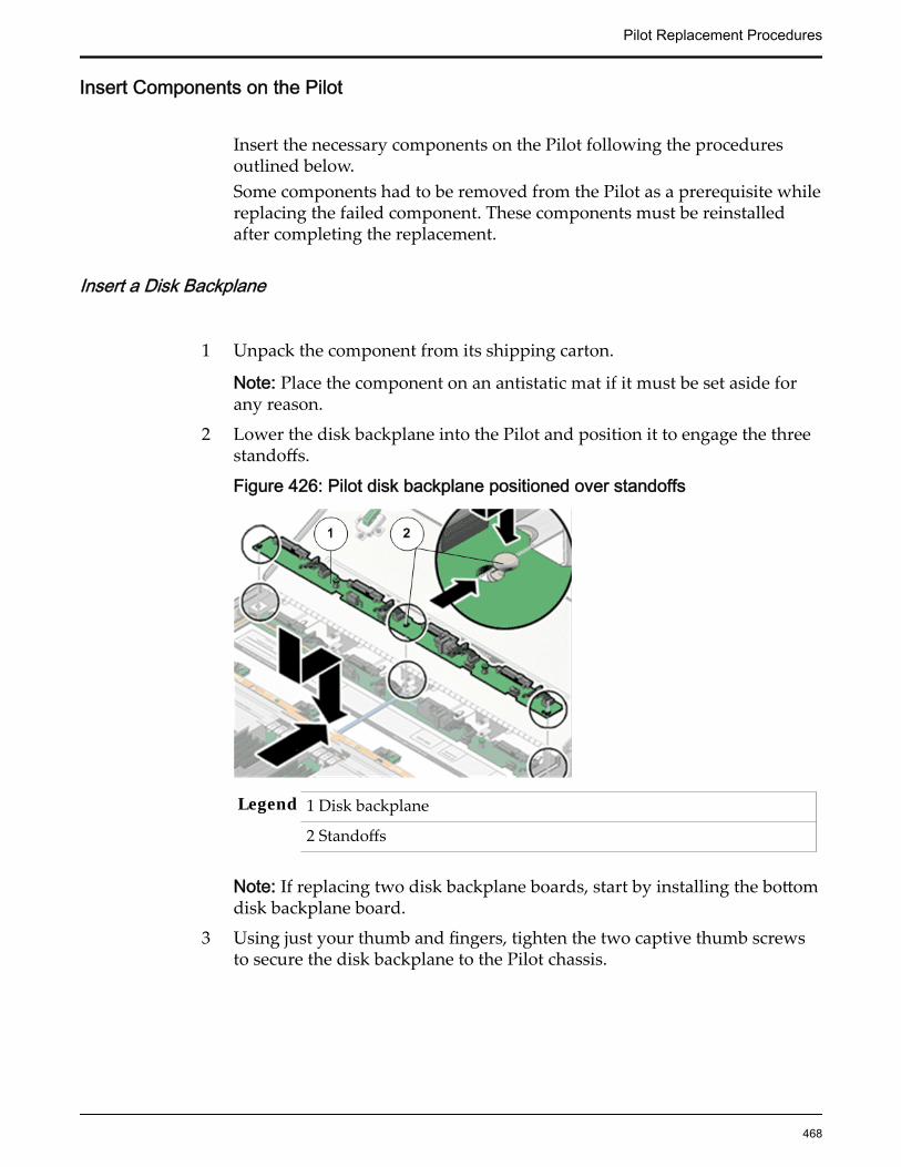
Insert Components on the Pilot
Insert the necessary components on the Pilot following the proceduresoutlined below.Some components had to be removed from the Pilot as a prerequisite whilereplacing the failed component. These components must be reinstalledafter completing the replacement.
Insert a Disk Backplane
1 Unpack the component from its shipping carton.
Note: Place the component on an antistatic mat if it must be set aside forany reason.
2 Lower the disk backplane into the Pilot and position it to engage the threestandoffs.
Figure 426: Pilot disk backplane positioned over standoffs
Legend 1 Disk backplane
2 Standoffs
Note: If replacing two disk backplane boards, start by installing the bottomdisk backplane board.
3 Using just your thumb and fingers, tighten the two captive thumb screwsto secure the disk backplane to the Pilot chassis.
Pilot Replacement Procedures
468
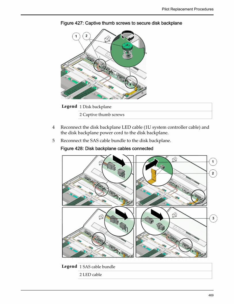
Figure 427: Captive thumb screws to secure disk backplane
Legend 1 Disk backplane
2 Captive thumb screws
4 Reconnect the disk backplane LED cable (1U system controller cable) andthe disk backplane power cord to the disk backplane.
5 Reconnect the SAS cable bundle to the disk backplane.
Figure 428: Disk backplane cables connected
Legend 1 SAS cable bundle
2 LED cable
Pilot Replacement Procedures
469

3 Disk backplane power cable
Note: After replacing the disk backplane, you must manually program theproduct serial number (PSN) into the replacement disk backplane.Programming the PSN on the disk backplane is important for serviceentitlement.
6 Reinstall all of the storage drives into the drive compartment.
Insert a SAS HDD
1 Unpack the component from its shipping carton.
Note: Place the component on an antistatic mat if it must be set aside forany reason.
2 Insert and slide the replacement SAS HDD into the drive slot until the SASHDD is fully seated into the slot.
Figure 429: SAS HDD insertion
Legend 1 Pilot front
2 SAS HDD
3 Drive carrier latch
3 Close the drive carrier latch to lock the SAS HDD in place.
Note: Do not force open the drive carrier latch. You can damage the drivecarrier latch if you apply too much force.
Pilot Replacement Procedures
470

Insert a SAS HBA
1 Unpack the component from its shipping carton.
Note: Place the component on an antistatic mat if it must be set aside forany reason.
2 Reconnect the SAS cable bundle into the HBA inside the riser.
3 Orient the SAS HBA so that the brackets of the HBA align with thealignment pin in the PCIe slot of the riser.
Figure 430: SAS HBA insertion into the riser
Legend 1 Riser board
2 SAS HBA
Important: Hold the SAS HBA by the edges. Do not touch the metalcontacts on the bottom of the card.
4 Push the connectors on the edge of the SAS HBA into the PCIe slot bypushing firmly to seat the card.
5 Apply firm pressure on each end of the SAS HBA alternately until it clicksinto place in the riser socket.
CAUTION: Support the SAS HBA and the riser as necessary to preventexcessive flexure. Otherwise, the SAS HBA or the riser card might break.
6 Insert the riser into the black slot on the Pilot motherboard and slide therelease tab backward to secure the riser in position.
Insert a Riser
1 Unpack the component from its shipping carton.
Pilot Replacement Procedures
471
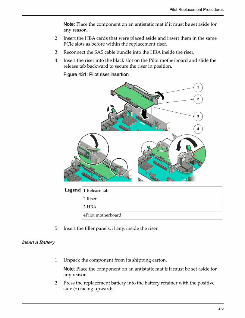
Note: Place the component on an antistatic mat if it must be set aside forany reason.
2 Insert the HBA cards that were placed aside and insert them in the samePCIe slots as before within the replacement riser.
3 Reconnect the SAS cable bundle into the HBA inside the riser.
4 Insert the riser into the black slot on the Pilot motherboard and slide therelease tab backward to secure the riser in position.
Figure 431: Pilot riser insertion
Legend 1 Release tab
2 Riser
3 HBA
4Pilot motherboard
5 Insert the filler panels, if any, inside the riser.
Insert a Battery
1 Unpack the component from its shipping carton.
Note: Place the component on an antistatic mat if it must be set aside forany reason.
2 Press the replacement battery into the battery retainer with the positiveside (+) facing upwards.
Pilot Replacement Procedures
472

Figure 432: Battery insertion
Legend 1 Pilot battery
2 Battery socket
If the Pilot is configured to synchronize with a network time server usingthe Network Time Protocol (NTP), the Oracle ILOM clock is reset as soonas the Pilot is powered on and connected to the network. Otherwise,proceed to the next step.
3 If the Pilot is not configured to use NTP, reset the Oracle ILOM clock usingthe Oracle ILOM CLI or the web interface. You can also reprogram theBIOS Setup utility to reprogram the host clock.For instructions, on setting the Oracle ILOM clock, see the OracleIntegrated Lights Out Manager (ILOM) 3.1 Documentation Library.
Insert a Pilot CPU
1 Unpack the component from its shipping carton.
Note: Place the component on an antistatic mat if it must be set aside forany reason.
2 Gently align the pins on the underside of the CPU to the CPU socket andpush down to secure the CPU in the socket.
Figure 433: CPU insertion
Pilot Replacement Procedures
473
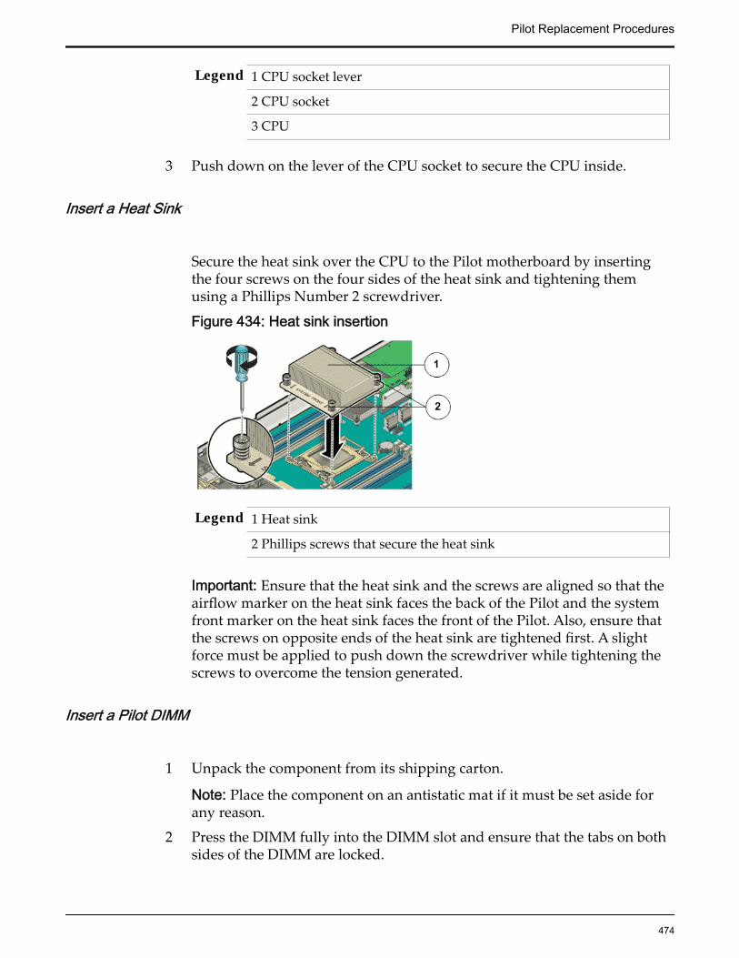
Legend 1 CPU socket lever
2 CPU socket
3 CPU
3 Push down on the lever of the CPU socket to secure the CPU inside.
Insert a Heat Sink
Secure the heat sink over the CPU to the Pilot motherboard by insertingthe four screws on the four sides of the heat sink and tightening themusing a Phillips Number 2 screwdriver.
Figure 434: Heat sink insertion
Legend 1 Heat sink
2 Phillips screws that secure the heat sink
Important: Ensure that the heat sink and the screws are aligned so that theairflow marker on the heat sink faces the back of the Pilot and the systemfront marker on the heat sink faces the front of the Pilot. Also, ensure thatthe screws on opposite ends of the heat sink are tightened first. A slightforce must be applied to push down the screwdriver while tightening thescrews to overcome the tension generated.
Insert a Pilot DIMM
1 Unpack the component from its shipping carton.
Note: Place the component on an antistatic mat if it must be set aside forany reason.
2 Press the DIMM fully into the DIMM slot and ensure that the tabs on bothsides of the DIMM are locked.
Pilot Replacement Procedures
474
Important: Ensure that the notch in the DIMM lines up with the key in theslot.
Note: Replace only one DIMM at a time to make sure that they are insertedinto the correct slots. Attempting to insert multiple DIMMs into the slotsmight damage the DIMMs due to excessive flexure.
Note: Never leave a DIMM slot unpopulated. Insert filler panels intoempty DIMM slots to ensure proper air flow inside the Pilot.
Insert the Fan Compartment
1 Move any loose cables so that they are against the Pilot chassis walls.
2 Align the fan compartment to where it installs into the Pilot chassis.
3 Slowly lower the fan compartment into the Pilot chassis, gently workingthe cables into the gaps between the fan compartment and the chassiswalls.
4 Verify that the fan compartment is properly seated, no cables are pinched,and the top surfaces of the fan compartment are flush with the Pilotchassis.
Insert a Fan Module
1 Unpack the component from its shipping carton.
Note: Place the component on an antistatic mat if it must be set aside forany reason.
2 Grasp the fan module tabs and press the fan down firmly into the fanmodule compartment.
Pilot Replacement Procedures
475
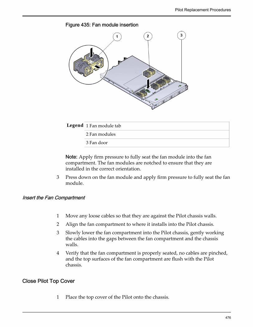
Figure 435: Fan module insertion
Legend 1 Fan module tab
2 Fan modules
3 Fan door
Note: Apply firm pressure to fully seat the fan module into the fancompartment. The fan modules are notched to ensure that they areinstalled in the correct orientation.
3 Press down on the fan module and apply firm pressure to fully seat the fanmodule.
Insert the Fan Compartment
1 Move any loose cables so that they are against the Pilot chassis walls.
2 Align the fan compartment to where it installs into the Pilot chassis.
3 Slowly lower the fan compartment into the Pilot chassis, gently workingthe cables into the gaps between the fan compartment and the chassiswalls.
4 Verify that the fan compartment is properly seated, no cables are pinched,and the top surfaces of the fan compartment are flush with the Pilotchassis.
Close Pilot Top Cover
1 Place the top cover of the Pilot onto the chassis.
Pilot Replacement Procedures
476
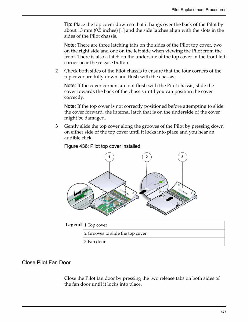
Tip: Place the top cover down so that it hangs over the back of the Pilot byabout 13 mm (0.5 inches) [1] and the side latches align with the slots in thesides of the Pilot chassis.
Note: There are three latching tabs on the sides of the Pilot top cover, twoon the right side and one on the left side when viewing the Pilot from thefront. There is also a latch on the underside of the top cover in the front leftcorner near the release button.
2 Check both sides of the Pilot chassis to ensure that the four corners of thetop cover are fully down and flush with the chassis.
Note: If the cover corners are not flush with the Pilot chassis, slide thecover towards the back of the chassis until you can position the covercorrectly.
Note: If the top cover is not correctly positioned before attempting to slidethe cover forward, the internal latch that is on the underside of the covermight be damaged.
3 Gently slide the top cover along the grooves of the Pilot by pressing downon either side of the top cover until it locks into place and you hear anaudible click.
Figure 436: Pilot top cover installed
Legend 1 Top cover
2 Grooves to slide the top cover
3 Fan door
Close Pilot Fan Door
Close the Pilot fan door by pressing the two release tabs on both sides ofthe fan door until it locks into place.
Pilot Replacement Procedures
477

Note: Close the Pilot fan door within 60 seconds to maintain adequateairflow to properly cool the Pilot. Leaving the door open for more than 60seconds, while the Pilot is running, might cause the Pilot to overheat andshut down. However, if power to the Pilot is switched off during thecomponent replacement procedure, the fan door can be left open.
Insert the Pilot Onto the Rack
Inserting the Pilot onto the rack includes the following tasks:
1 Install the Pilot chassis onto the rack.
2 Re-connect the Pilot cabling and the cable management arm (CMA).
3 Connect the power cords onto the Pilot.
4 Slide the Pilot into rack position.
5 Update the Pilot BIOS.
6 Power on the Pilot host.
7 Verify the Pilot component status.
Insert Pilot Chassis Into Rack
1 With the help of a partner or a mechanical lift, raise the Pilot so that theback ends of the mounting brackets are aligned with the slide-railassemblies that are mounted in the rack.
Figure 437: Lift Pilot chassis onto rack
Pilot Replacement Procedures
478

Legend 1 Inserting mounting brackets into slide-rails
2 Slide-rail release button
3 Slide-rail lock
CAUTION: Deploy any rack anti-tilt mechanisms before installing the Pilotinto the rack.
CAUTION: The Pilot weighs approximately 18.1 kg (39.9 lb). Two peopleare required to carry the chassis and install it into the rack.
CAUTION: Do not use the power supply handles to lift the chassis. Usingthe power supply handles to lift the chassis can damage the powersupplies and disrupt electrical power to the Pilot.
2 Insert the mounting brackets into the slide-rails, then push the Pilot intothe rack until the mounting brackets encounter the slide-rail stops atapproximately 12 inches (30 cm).The Pilot is now in the extended maintenance position.
Slide Pilot to Rack Position
1 Simultaneously pull and hold the two release tabs, one on each side of thePilot, toward the front of the Pilot while you push the Pilot into the rack.
Figure 438: Location of the Pilot release tabs
Note: As you push the Pilot into the rack, verify that the cable managementarm (CMA) retracts without binding.
Note: To pull the Pilot release tab, place your finger in the center of the tab,not on the end, and apply pressure as you pull the tab toward the front ofthe Pilot.
2 Continue pushing the Pilot into the rack until the slide-rail locks on thefront of the Pilot engage the slide-rail assemblies.
Pilot Replacement Procedures
479

Note: The Pilot locks into the rack position with an audible click.
Re-connect Pilot Cabling
1 Reconnect the following cables that had been disconnected from the Pilot.
• Ethernet cables connected to the network ports
• Rollover cable connected to the serial port
Note: If the cable management arm (CMA) is in the way, extend the Pilotapproximately 13 cm (5 inches) out of the front of the rack. Once the cablesare connected to the ports, the Pilot can be pushed back into the rackposition.
2 Reconnect the power cords to the power supplies and secure them with thevelcro straps.
3 If necessary, reinstall the cables into the cable management arm (CMA) andsecure them with cable straps.
4 Reconnect the CMA to the Pilot chassis by reattaching the release tabs onboth sides of the CMA.
Connect Power Cords On the Pilot
Reconnect the power cords to the Pilot.
Note: After the power cords are connected, the green SP LED and the OKLED both start to blink.
Note: Do not turn on the power to the Pilot host immediately. The poweron the Pilot host is turned on only after updating the Pilot BIOS. Turningon the power to the Pilot host early can prevent the Pilot from booting afterthe Pilot BIOS is updated.
Verify Component Replacement on the Standby PilotIf you replaced a component on the standby Pilot, complete the following stepsto verify the status of the Pilot:
1 Return to Guided Maintenance and click Finish.
Guided Maintenance closes and the GUI displays the Pilot Overview page.
2 From the Pilot Overview page, review the status of the Pilot.A status of Normal requires no action.
Pilot Replacement Procedures
480
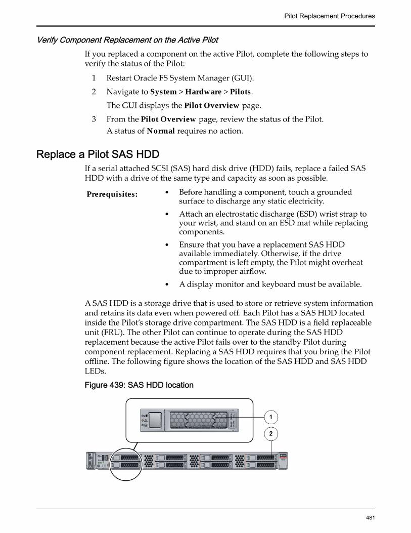
Verify Component Replacement on the Active PilotIf you replaced a component on the active Pilot, complete the following steps toverify the status of the Pilot:
1 Restart Oracle FS System Manager (GUI).
2 Navigate to System > Hardware > Pilots.
The GUI displays the Pilot Overview page.
3 From the Pilot Overview page, review the status of the Pilot.A status of Normal requires no action.
Replace a Pilot SAS HDDIf a serial attached SCSI (SAS) hard disk drive (HDD) fails, replace a failed SASHDD with a drive of the same type and capacity as soon as possible.
Prerequisites: • Before handling a component, touch a groundedsurface to discharge any static electricity.
• Attach an electrostatic discharge (ESD) wrist strap toyour wrist, and stand on an ESD mat while replacingcomponents.
• Ensure that you have a replacement SAS HDDavailable immediately. Otherwise, if the drivecompartment is left empty, the Pilot might overheatdue to improper airflow.
• A display monitor and keyboard must be available.
A SAS HDD is a storage drive that is used to store or retrieve system informationand retains its data even when powered off. Each Pilot has a SAS HDD locatedinside the Pilot’s storage drive compartment. The SAS HDD is a field replaceableunit (FRU). The other Pilot can continue to operate during the SAS HDDreplacement because the active Pilot fails over to the standby Pilot duringcomponent replacement. Replacing a SAS HDD requires that you bring the Pilotoffline. The following figure shows the location of the SAS HDD and SAS HDDLEDs.
Figure 439: SAS HDD location
Pilot Replacement Procedures
481

Legend 1 SAS HDD (bottom slot)
2 Pilot front
Note: Replacing the failed SAS HDD with a blank SAS HDD into the Pilot driveslot does not start up the Pilot. Use Guided Maintenance (GM) to re-install theoperating system on the Pilot SAS HDD, which enables the Pilot to re-join theOracle FS System automatically.
Procedure Overview
1 Prepare a Pilot for Component Replacement
2 Remove a SAS HDD
3 Insert a SAS HDD
4 Create a Pilot Image on Replacement SAS HDD
5 Verify Component Replacement on the Standby Pilot
6 Verify Component Replacement on the Active Pilot
Prepare a Pilot for Component Replacement1 Contact Oracle Customer Support prior to replacing a Pilot component.
Oracle Customer Support identifies the failed component on the Pilot foryou.
2 From Oracle FS System Manager (GUI), navigate to System > Hardware >Pilots and select the Pilot that contains the component that you want toreplace.
3 Select Actions > Repair Pilot.Guided Maintenance displays the list of Pilot components.
4 Based on the information from your Oracle Customer Supportrepresentative, select the correct component from the list.
5 Click Next.Guided Maintenance sends a request to flash the LEDs on the Pilot to helpyou locate the Pilot in the data center.
6 Click Next.
Guided Maintenance displays a link to Pilot Repair Procedures.7 Click the Pilot Repair Procedures link to open and print the procedures.8 Click Next.
• If you are replacing a component located on the active Pilot, GuidedMaintenance takes the active Pilot offline and fails over to thestandby Pilot. After the active Pilot is offline, the GUI closes. Youmay now safely disconnect the power cords.
• If you are replacing a component located on the standby Pilot,Guided Maintenance takes the standby Pilot offline. After the
Pilot Replacement Procedures
482

standby Pilot is offline, you may safely disconnect the power cordsand data cables. When servicing the standby Pilot, failover is notrequired.
• If you are replacing a power supply, you are not required to bringthe Pilot offline. The power supplies are hot-serviceable. The powersupplies are the only Pilot components that do not require the Pilotto be brought offline. You can replace one power supply withoutbringing the Pilot offline, as long as the second power supplyremains online and operational.
Remove a SAS HDD
1 On the Pilot with the failed SAS HDD, press the drive carrier latch todisengage the SAS HDD.
Figure 440: SAS HDD removal
Legend 1 Pilot front
2 SAS HDD
3 Drive carrier latch
Important: The drive carrier latch is not an ejector. Do not bend the latchtoo far to the right. Bending the latch can damage the latch.
Important: When you remove a failed SAS HDD, be sure to replace itimmediately with another SAS HDD or a filler panel.
2 Grasp the drive carrier latch and pull the SAS HDD out of the Pilot drivecompartment.
3 Place the failed SAS HDD on an antistatic mat.
Pilot Replacement Procedures
483
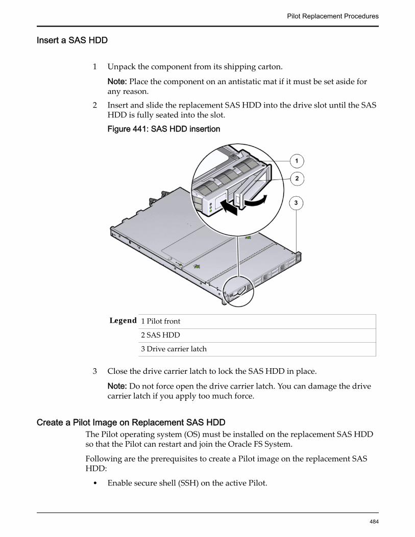
Insert a SAS HDD
1 Unpack the component from its shipping carton.
Note: Place the component on an antistatic mat if it must be set aside forany reason.
2 Insert and slide the replacement SAS HDD into the drive slot until the SASHDD is fully seated into the slot.
Figure 441: SAS HDD insertion
Legend 1 Pilot front
2 SAS HDD
3 Drive carrier latch
3 Close the drive carrier latch to lock the SAS HDD in place.
Note: Do not force open the drive carrier latch. You can damage the drivecarrier latch if you apply too much force.
Create a Pilot Image on Replacement SAS HDDThe Pilot operating system (OS) must be installed on the replacement SAS HDDso that the Pilot can restart and join the Oracle FS System.
Following are the prerequisites to create a Pilot image on the replacement SASHDD:
• Enable secure shell (SSH) on the active Pilot.
Pilot Replacement Procedures
484

• HTTP and DHCP servers: Use dnsmasq as the HTTP and DHCP server.Configuration files for dnsmasq are located at /var/lib/axiom/dnsmasq_svc.conf. The lease file for dnsmasq is located at /var/lib/axiom/dnsmasq_svc.leases.
• NET-2 port to enable Guided Maintenance on the alternate Pilot: Using theNET-2 port allows the Oracle FS System to be operational, while GM isperformed on the Pilot on which the SAS HDD is replaced.
1 Unplug the cable attached to NET-2 port at the back of the Pilot where theSAS HDD must be replaced. Also, unplug the cable from NET MGT portand plug it into NET-2.
2 On the existing Pilot, flush the DHCP lease file located on the operationalPilot at /var/lib/axiom/dnsmasq_svc.leases. and restart the service.[root@pilot1 /]# echo “” > /var/lib/axiom/dnsmasq_svc.leases
3 Restart the dnsmasq service.[root@pilot1 /]# service dnsmasq_svc restartNote: The dnsmasq is the DHCP server and must be restarted after theDHCP lease file was flushed, so that the Pilot to be repaired can acquire afresh IP address that will be used for the kick-start installation.
4 Power on the Pilot with the replacement SAS HDD.
Note: You might not need to press the F12 function key because NetworkBoot and HDD are the default boot order.
Note: When the Pilot with the replacement SAS HDD is powered on, theNET–2 port boots up and starts downloading all the necessary RPMpackages and files from the buddy Pilot, and enables the Pilot to restartautomatically and join the Oracle FS System.
5 Wait for 20 minutes and then ping the external IP addresses of the Pilotthat contains the replacement drive.A ping reply indicates that thePilot OS has been installed successfully onthe SAS HDD.
6 Reconnect the cabling that had been disconnected from the Pilot as follows:
• Unplug the cable from NET-2 port
• Move the cable to the NET MGT port and restore the original NET-2cable.
• Reconnect the Ethernet cables between the NET-2 port and the NETMGT port on other Pilot.
7 Repeat steps 2 and 3 to flush the DHCP lease files and restart the DHCPserver.
Verify Component Replacement on the Standby PilotIf you replaced a component on the standby Pilot, complete the following stepsto verify the status of the Pilot:
Pilot Replacement Procedures
485
1 Return to Guided Maintenance and click Finish.
Guided Maintenance closes and the GUI displays the Pilot Overview page.
2 From the Pilot Overview page, review the status of the Pilot.A status of Normal requires no action.
Verify Component Replacement on the Active PilotIf you replaced a component on the active Pilot, complete the following steps toverify the status of the Pilot:
1 Restart Oracle FS System Manager (GUI).
2 Navigate to System > Hardware > Pilots.
The GUI displays the Pilot Overview page.
3 From the Pilot Overview page, review the status of the Pilot.A status of Normal requires no action.
Replace a Pilot Disk BackplaneThe disk backplane serves as an interface between the storage drives and theserial-attached SCSI (SAS) host bus adapter (HBA) in the Pilot. If damaged, thefailed disk backplane must be replaced as soon as possible.
Prerequisites: • Before handling a component, touch a groundedsurface to discharge any static electricity.
• Attach an electrostatic discharge (ESD) wrist strap toyour wrist, and stand on an ESD mat while replacingcomponents.
• Make sure you have a Phillips flat-head screwdriver .• Fail over the Pilot before replacing the component
using Guided Maintenance.
Note: The Pilot must be failed over to prevent dataloss or data corruption during the componentreplacement process.
Each Pilot has two disk backplanes located behind the drive compartment. Thedisk backplane is a field replaceable unit (FRU). Replacing a disk backplanerequires you to bring the Pilot offline. The following figure shows the location ofthe disk backplane inside the Pilot.
Pilot Replacement Procedures
486
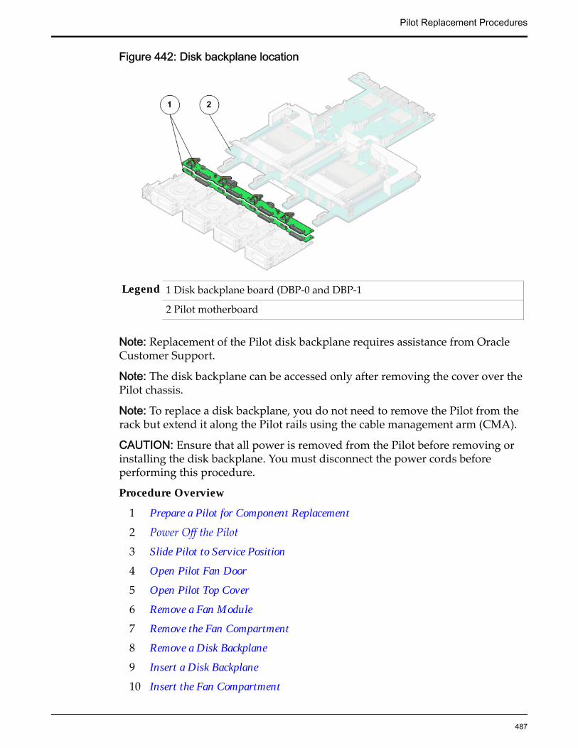
Figure 442: Disk backplane location
Legend 1 Disk backplane board (DBP-0 and DBP-1
2 Pilot motherboard
Note: Replacement of the Pilot disk backplane requires assistance from OracleCustomer Support.
Note: The disk backplane can be accessed only after removing the cover over thePilot chassis.
Note: To replace a disk backplane, you do not need to remove the Pilot from therack but extend it along the Pilot rails using the cable management arm (CMA).
CAUTION: Ensure that all power is removed from the Pilot before removing orinstalling the disk backplane. You must disconnect the power cords beforeperforming this procedure.
Procedure Overview
1 Prepare a Pilot for Component Replacement
2 Power Off the Pilot
3 Slide Pilot to Service Position
4 Open Pilot Fan Door
5 Open Pilot Top Cover
6 Remove a Fan Module
7 Remove the Fan Compartment
8 Remove a Disk Backplane
9 Insert a Disk Backplane
10 Insert the Fan Compartment
Pilot Replacement Procedures
487

11 Insert a Fan Module
12 Close Pilot Top Cover
13 Close Pilot Fan Door
14 Slide Pilot to Rack Position
15 Connect Power Cords On the Pilot
16 Verify Component Replacement on the Standby Pilot
17 Verify Component Replacement on the Active Pilot
Prepare a Pilot for Component Replacement1 Contact Oracle Customer Support prior to replacing a Pilot component.
Oracle Customer Support identifies the failed component on the Pilot foryou.
2 From Oracle FS System Manager (GUI), navigate to System > Hardware >Pilots and select the Pilot that contains the component that you want toreplace.
3 Select Actions > Repair Pilot.Guided Maintenance displays the list of Pilot components.
4 Based on the information from your Oracle Customer Supportrepresentative, select the correct component from the list.
5 Click Next.Guided Maintenance sends a request to flash the LEDs on the Pilot to helpyou locate the Pilot in the data center.
6 Click Next.
Guided Maintenance displays a link to Pilot Repair Procedures.
7 Click the Pilot Repair Procedures link to open and print the procedures.
8 Click Next.
• If you are replacing a component located on the active Pilot, GuidedMaintenance takes the active Pilot offline and fails over to thestandby Pilot. After the active Pilot is offline, the GUI closes. Youmay now safely disconnect the power cords.
• If you are replacing a component located on the standby Pilot,Guided Maintenance takes the standby Pilot offline. After thestandby Pilot is offline, you may safely disconnect the power cordsand data cables. When servicing the standby Pilot, failover is notrequired.
• If you are replacing a power supply, you are not required to bringthe Pilot offline. The power supplies are hot-serviceable. The powersupplies are the only Pilot components that do not require the Pilotto be brought offline. You can replace one power supply without
Pilot Replacement Procedures
488

bringing the Pilot offline, as long as the second power supplyremains online and operational.
Power Off the Pilot
Note: Do not power off the Pilot host without ensuring that SSH is enabled onthe Oracle FS System. Otherwise, the replacement procedure might fail. The Pilothost is shut down when guided maintenance is started.
1 Notify affected users that the Pilot will be shut down.
2 Ensure that the host of the Pilot on which the replacement procedure mustbe performed is powered off.
Slide Pilot to Service Position
1 When Guided Maintenance prompts you to remove the component, pullthe white tab that is located behind the slide lockout release tabs to fullyrelease the chassis from the slide.
Figure 443: Pilot slide lockout release tabs
Legend 1 Slide rail lock
2 Slide lockout release tab
Note: The slide-rail locks are located behind the flip-down handles on thefront of the Pilot chassis. The slide-rail locks are released when the flip-down handles are pulled down. The slide lockout release tab must bereleased to push the Pilot chassis back into the rack.
Pilot Replacement Procedures
489
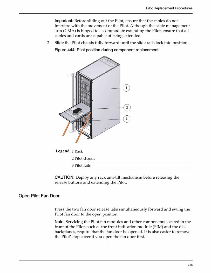
Important: Before sliding out the Pilot, ensure that the cables do notinterfere with the movement of the Pilot. Although the cable managementarm (CMA) is hinged to accommodate extending the Pilot, ensure that allcables and cords are capable of being extended.
2 Slide the Pilot chassis fully forward until the slide rails lock into position.
Figure 444: Pilot position during component replacement
Legend 1 Rack
2 Pilot chassis
3 Pilot rails
CAUTION: Deploy any rack anti-tilt mechanism before releasing therelease buttons and extending the Pilot.
Open Pilot Fan Door
Press the two fan door release tabs simultaneously forward and swing thePilot fan door to the open position.
Note: Servicing the Pilot fan modules and other components located in thefront of the Pilot, such as the front indication module (FIM) and the diskbackplanes, require that the fan door be opened. It is also easier to removethe Pilot’s top cover if you open the fan door first.
Pilot Replacement Procedures
490
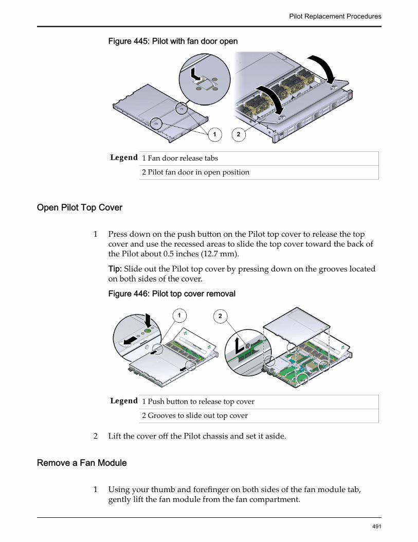
Figure 445: Pilot with fan door open
Legend 1 Fan door release tabs
2 Pilot fan door in open position
Open Pilot Top Cover
1 Press down on the push button on the Pilot top cover to release the topcover and use the recessed areas to slide the top cover toward the back ofthe Pilot about 0.5 inches (12.7 mm).
Tip: Slide out the Pilot top cover by pressing down on the grooves locatedon both sides of the cover.
Figure 446: Pilot top cover removal
Legend 1 Push button to release top cover
2 Grooves to slide out top cover
2 Lift the cover off the Pilot chassis and set it aside.
Remove a Fan Module
1 Using your thumb and forefinger on both sides of the fan module tab,gently lift the fan module from the fan compartment.
Pilot Replacement Procedures
491
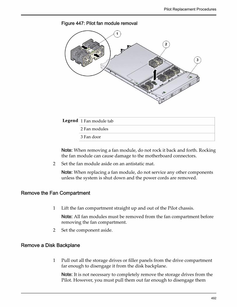
Figure 447: Pilot fan module removal
Legend 1 Fan module tab
2 Fan modules
3 Fan door
Note: When removing a fan module, do not rock it back and forth. Rockingthe fan module can cause damage to the motherboard connectors.
2 Set the fan module aside on an antistatic mat.
Note: When replacing a fan module, do not service any other componentsunless the system is shut down and the power cords are removed.
Remove the Fan Compartment
1 Lift the fan compartment straight up and out of the Pilot chassis.
Note: All fan modules must be removed from the fan compartment beforeremoving the fan compartment.
2 Set the component aside.
Remove a Disk Backplane
1 Pull out all the storage drives or filler panels from the drive compartmentfar enough to disengage it from the disk backplane.
Note: It is not necessary to completely remove the storage drives from thePilot. However, you must pull them out far enough to disengage them
Pilot Replacement Procedures
492

from the disk backplane. If you remove the storage drives from the Pilot,make a note of their locations so that you can reinstall the storage drives inthe same locations.
2 If replacing both disk backplane boards, disconnect the SAS cable bundlestarting with the top board of the disk backplane.If you are going to remove and replace both disk backplane boards, make anote of which cables connect to the top disk backplane and which cablesconnect to the bottom disk backplane. Do this before disconnecting anybackplane cables.
Figure 448: Disk backplane cables disconnected
Legend 1 Disk backplane power cable
2 LED cable
3 SAS cable bundle
3 Disconnect the disk backplane LED cable (1U system controller cable) andthe disk backplane power cord from the disk backplane.
4 Using your thumb and fingers, loosen the two captive thumb screws thatsecure the disk backplane to the Pilot chassis.
Pilot Replacement Procedures
493

Figure 449: Captive thumb screws to remove disk backplane
Legend 1 Captive thumb screws
2 Disk backplane
5 Slide the disk backplane forward toward the front of the Pilot to release itfrom the three standoffs and lift it out of the chassis.
Figure 450: Pilot disk backplane removal
Legend 1 Disk backplane
2 Standoffs
6 Place the disk backplane on an antistatic mat.If replacing both disk backplane boards, repeat the steps for the secondboard.
Pilot Replacement Procedures
494

Insert a Disk Backplane
1 Unpack the component from its shipping carton.
Note: Place the component on an antistatic mat if it must be set aside forany reason.
2 Lower the disk backplane into the Pilot and position it to engage the threestandoffs.
Figure 451: Pilot disk backplane positioned over standoffs
Legend 1 Disk backplane
2 Standoffs
Note: If replacing two disk backplane boards, start by installing the bottomdisk backplane board.
3 Using just your thumb and fingers, tighten the two captive thumb screwsto secure the disk backplane to the Pilot chassis.
Figure 452: Captive thumb screws to secure disk backplane
Pilot Replacement Procedures
495
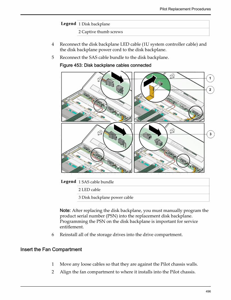
Legend 1 Disk backplane
2 Captive thumb screws
4 Reconnect the disk backplane LED cable (1U system controller cable) andthe disk backplane power cord to the disk backplane.
5 Reconnect the SAS cable bundle to the disk backplane.
Figure 453: Disk backplane cables connected
Legend 1 SAS cable bundle
2 LED cable
3 Disk backplane power cable
Note: After replacing the disk backplane, you must manually program theproduct serial number (PSN) into the replacement disk backplane.Programming the PSN on the disk backplane is important for serviceentitlement.
6 Reinstall all of the storage drives into the drive compartment.
Insert the Fan Compartment
1 Move any loose cables so that they are against the Pilot chassis walls.
2 Align the fan compartment to where it installs into the Pilot chassis.
Pilot Replacement Procedures
496
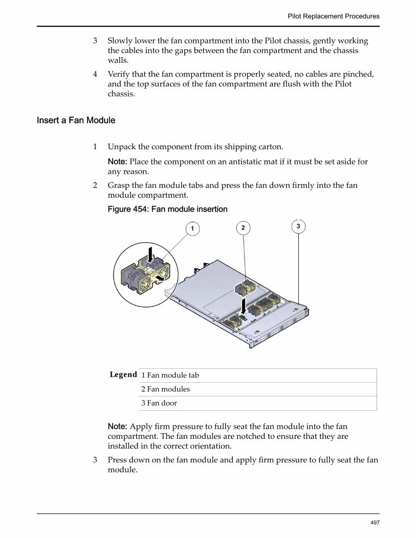
3 Slowly lower the fan compartment into the Pilot chassis, gently workingthe cables into the gaps between the fan compartment and the chassiswalls.
4 Verify that the fan compartment is properly seated, no cables are pinched,and the top surfaces of the fan compartment are flush with the Pilotchassis.
Insert a Fan Module
1 Unpack the component from its shipping carton.
Note: Place the component on an antistatic mat if it must be set aside forany reason.
2 Grasp the fan module tabs and press the fan down firmly into the fanmodule compartment.
Figure 454: Fan module insertion
Legend 1 Fan module tab
2 Fan modules
3 Fan door
Note: Apply firm pressure to fully seat the fan module into the fancompartment. The fan modules are notched to ensure that they areinstalled in the correct orientation.
3 Press down on the fan module and apply firm pressure to fully seat the fanmodule.
Pilot Replacement Procedures
497

Close Pilot Top Cover
1 Place the top cover of the Pilot onto the chassis.
Tip: Place the top cover down so that it hangs over the back of the Pilot byabout 13 mm (0.5 inches) [1] and the side latches align with the slots in thesides of the Pilot chassis.
Note: There are three latching tabs on the sides of the Pilot top cover, twoon the right side and one on the left side when viewing the Pilot from thefront. There is also a latch on the underside of the top cover in the front leftcorner near the release button.
2 Check both sides of the Pilot chassis to ensure that the four corners of thetop cover are fully down and flush with the chassis.
Note: If the cover corners are not flush with the Pilot chassis, slide thecover towards the back of the chassis until you can position the covercorrectly.
Note: If the top cover is not correctly positioned before attempting to slidethe cover forward, the internal latch that is on the underside of the covermight be damaged.
3 Gently slide the top cover along the grooves of the Pilot by pressing downon either side of the top cover until it locks into place and you hear anaudible click.
Figure 455: Pilot top cover installed
Legend 1 Top cover
2 Grooves to slide the top cover
3 Fan door
Close Pilot Fan Door
Pilot Replacement Procedures
498

Close the Pilot fan door by pressing the two release tabs on both sides ofthe fan door until it locks into place.
Note: Close the Pilot fan door within 60 seconds to maintain adequateairflow to properly cool the Pilot. Leaving the door open for more than 60seconds, while the Pilot is running, might cause the Pilot to overheat andshut down. However, if power to the Pilot is switched off during thecomponent replacement procedure, the fan door can be left open.
Slide Pilot to Rack Position
1 Simultaneously pull and hold the two release tabs, one on each side of thePilot, toward the front of the Pilot while you push the Pilot into the rack.
Figure 456: Location of the Pilot release tabs
Note: As you push the Pilot into the rack, verify that the cable managementarm (CMA) retracts without binding.
Note: To pull the Pilot release tab, place your finger in the center of the tab,not on the end, and apply pressure as you pull the tab toward the front ofthe Pilot.
2 Continue pushing the Pilot into the rack until the slide-rail locks on thefront of the Pilot engage the slide-rail assemblies.
Note: The Pilot locks into the rack position with an audible click.
Connect Power Cords On the Pilot
Reconnect the power cords to the Pilot.
Note: After the power cords are connected, the green SP LED and the OKLED both start to blink.
Pilot Replacement Procedures
499
Note: Do not turn on the power to the Pilot host immediately. The poweron the Pilot host is turned on only after updating the Pilot BIOS. Turningon the power to the Pilot host early can prevent the Pilot from booting afterthe Pilot BIOS is updated.
Verify Component Replacement on the Standby PilotIf you replaced a component on the standby Pilot, complete the following stepsto verify the status of the Pilot:
1 Return to Guided Maintenance and click Finish.
Guided Maintenance closes and the GUI displays the Pilot Overview page.
2 From the Pilot Overview page, review the status of the Pilot.A status of Normal requires no action.
Verify Component Replacement on the Active PilotIf you replaced a component on the active Pilot, complete the following steps toverify the status of the Pilot:
1 Restart Oracle FS System Manager (GUI).
2 Navigate to System > Hardware > Pilots.
The GUI displays the Pilot Overview page.
3 From the Pilot Overview page, review the status of the Pilot.A status of Normal requires no action.
Replace a Pilot Heat SinkIf a heat sink fails, the heat generated from the central processing units (CPUs)inside the Pilot will not be circulated and the internal temperature of the Pilotcan rise quickly causing a possible CPU failure and a Pilot shutdown. Heat sinksare usually durable and do not need to be replaced but a damaged heat sinkmight be replaced if it stops working efficiently, usually if the thermal grease onthe heat sink has dried out.
Prerequisites: • Before handling a component, touch a groundedsurface to discharge any static electricity.
• Attach an electrostatic discharge (ESD) wrist strap toyour wrist, and stand on an ESD mat while replacingcomponents.
• Ensure that you have a Phillips Number 2screwdriver with at least a four-inch shaft.
Pilot Replacement Procedures
500

• Ensure that you have thermal grease and syringeavailable to clean the CPU and heat sink.
• Fail over the Pilot before replacing the componentusing Guided Maintenance.
Note: The Pilot must be failed over to prevent dataloss or data corruption during the componentreplacement process.
Each Pilot has two heat sinks located above the CPUs. Heat sinks are fieldreplaceable units (FRUs) and are not hot-swappable. Replacing a heat sinkrequires you to bring the Pilot offline. The following figure shows the two heatsinks inside the Pilot.
Figure 457: Heat sink location
Legend 1 Heat sink
2 Pilot
Note: The heat sinks can be accessed only after removing the cover over the Pilotchassis.
Note: To replace a heat sink, you do not need to remove the Pilot from the rackbut extend it along the Pilot rails using the cable management arm (CMA).
CAUTION: Replacement of the Pilot heat sink requires assistance from OracleCustomer Support.
CAUTION: Ensure that all power is removed from the Pilot before replacing theheat sink. Disconnect the power cables before performing the heat sinkreplacement procedure.
Procedure Overview
1 Prepare a Pilot for Component Replacement
2 Power Off the Pilot
Pilot Replacement Procedures
501
3 Slide Pilot to Service Position
4 Open Pilot Fan Door
5 Open Pilot Top Cover
6 Remove an Air Duct
7 Remove a Heat Sink
8 Insert a Heat Sink
9 Insert an Air Duct
10 Close Pilot Top Cover
11 Close Pilot Fan Door
12 Slide Pilot to Rack Position
13 Connect Power Cords On the Pilot
14 Verify Component Replacement on the Standby Pilot
15 Verify Component Replacement on the Active Pilot
Prepare a Pilot for Component Replacement1 Contact Oracle Customer Support prior to replacing a Pilot component.
Oracle Customer Support identifies the failed component on the Pilot foryou.
2 From Oracle FS System Manager (GUI), navigate to System > Hardware >Pilots and select the Pilot that contains the component that you want toreplace.
3 Select Actions > Repair Pilot.Guided Maintenance displays the list of Pilot components.
4 Based on the information from your Oracle Customer Supportrepresentative, select the correct component from the list.
5 Click Next.Guided Maintenance sends a request to flash the LEDs on the Pilot to helpyou locate the Pilot in the data center.
6 Click Next.
Guided Maintenance displays a link to Pilot Repair Procedures.7 Click the Pilot Repair Procedures link to open and print the procedures.8 Click Next.
• If you are replacing a component located on the active Pilot, GuidedMaintenance takes the active Pilot offline and fails over to thestandby Pilot. After the active Pilot is offline, the GUI closes. Youmay now safely disconnect the power cords.
• If you are replacing a component located on the standby Pilot,Guided Maintenance takes the standby Pilot offline. After the
Pilot Replacement Procedures
502
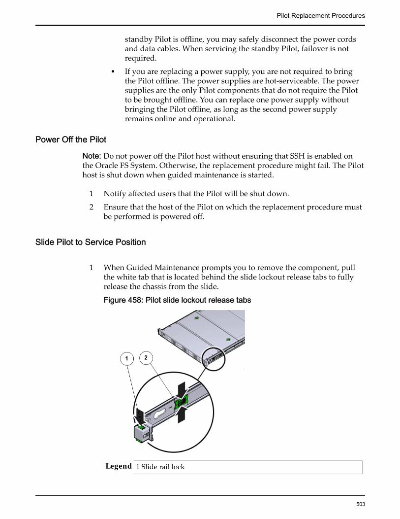
standby Pilot is offline, you may safely disconnect the power cordsand data cables. When servicing the standby Pilot, failover is notrequired.
• If you are replacing a power supply, you are not required to bringthe Pilot offline. The power supplies are hot-serviceable. The powersupplies are the only Pilot components that do not require the Pilotto be brought offline. You can replace one power supply withoutbringing the Pilot offline, as long as the second power supplyremains online and operational.
Power Off the Pilot
Note: Do not power off the Pilot host without ensuring that SSH is enabled onthe Oracle FS System. Otherwise, the replacement procedure might fail. The Pilothost is shut down when guided maintenance is started.
1 Notify affected users that the Pilot will be shut down.
2 Ensure that the host of the Pilot on which the replacement procedure mustbe performed is powered off.
Slide Pilot to Service Position
1 When Guided Maintenance prompts you to remove the component, pullthe white tab that is located behind the slide lockout release tabs to fullyrelease the chassis from the slide.
Figure 458: Pilot slide lockout release tabs
Legend 1 Slide rail lock
Pilot Replacement Procedures
503

2 Slide lockout release tab
Note: The slide-rail locks are located behind the flip-down handles on thefront of the Pilot chassis. The slide-rail locks are released when the flip-down handles are pulled down. The slide lockout release tab must bereleased to push the Pilot chassis back into the rack.
Important: Before sliding out the Pilot, ensure that the cables do notinterfere with the movement of the Pilot. Although the cable managementarm (CMA) is hinged to accommodate extending the Pilot, ensure that allcables and cords are capable of being extended.
2 Slide the Pilot chassis fully forward until the slide rails lock into position.
Figure 459: Pilot position during component replacement
Legend 1 Rack
2 Pilot chassis
3 Pilot rails
CAUTION: Deploy any rack anti-tilt mechanism before releasing therelease buttons and extending the Pilot.
Open Pilot Fan Door
Press the two fan door release tabs simultaneously forward and swing thePilot fan door to the open position.
Pilot Replacement Procedures
504

Note: Servicing the Pilot fan modules and other components located in thefront of the Pilot, such as the front indication module (FIM) and the diskbackplanes, require that the fan door be opened. It is also easier to removethe Pilot’s top cover if you open the fan door first.
Figure 460: Pilot with fan door open
Legend 1 Fan door release tabs
2 Pilot fan door in open position
Open Pilot Top Cover
1 Press down on the push button on the Pilot top cover to release the topcover and use the recessed areas to slide the top cover toward the back ofthe Pilot about 0.5 inches (12.7 mm).
Tip: Slide out the Pilot top cover by pressing down on the grooves locatedon both sides of the cover.
Figure 461: Pilot top cover removal
Legend 1 Push button to release top cover
2 Grooves to slide out top cover
2 Lift the cover off the Pilot chassis and set it aside.
Pilot Replacement Procedures
505
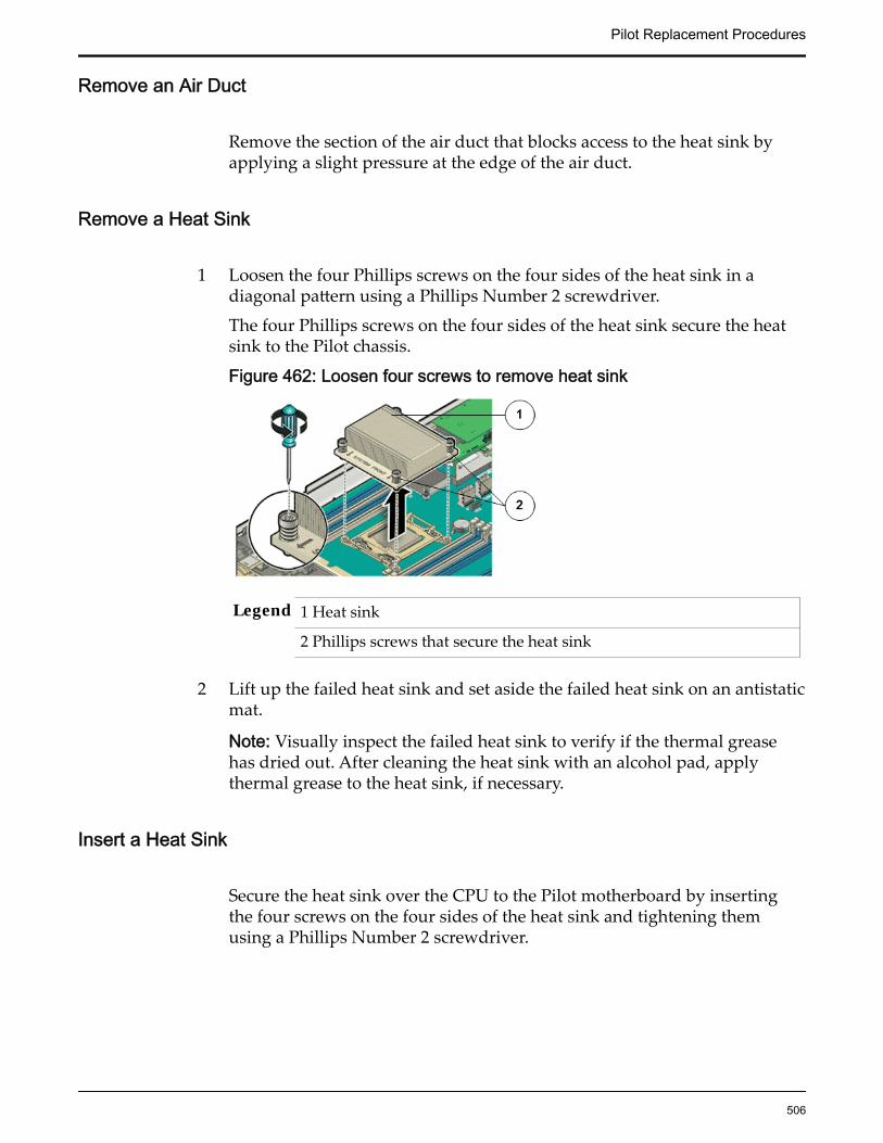
Remove an Air Duct
Remove the section of the air duct that blocks access to the heat sink byapplying a slight pressure at the edge of the air duct.
Remove a Heat Sink
1 Loosen the four Phillips screws on the four sides of the heat sink in adiagonal pattern using a Phillips Number 2 screwdriver.
The four Phillips screws on the four sides of the heat sink secure the heatsink to the Pilot chassis.
Figure 462: Loosen four screws to remove heat sink
Legend 1 Heat sink
2 Phillips screws that secure the heat sink
2 Lift up the failed heat sink and set aside the failed heat sink on an antistaticmat.
Note: Visually inspect the failed heat sink to verify if the thermal greasehas dried out. After cleaning the heat sink with an alcohol pad, applythermal grease to the heat sink, if necessary.
Insert a Heat Sink
Secure the heat sink over the CPU to the Pilot motherboard by insertingthe four screws on the four sides of the heat sink and tightening themusing a Phillips Number 2 screwdriver.
Pilot Replacement Procedures
506

Figure 463: Heat sink insertion
Legend 1 Heat sink
2 Phillips screws that secure the heat sink
Important: Ensure that the heat sink and the screws are aligned so that theairflow marker on the heat sink faces the back of the Pilot and the systemfront marker on the heat sink faces the front of the Pilot. Also, ensure thatthe screws on opposite ends of the heat sink are tightened first. A slightforce must be applied to push down the screwdriver while tightening thescrews to overcome the tension generated.
Insert an Air Duct
Replace the section of the air duct that had been removed earlier and snapit firmly into position by applying a slight pressure at the edge of the airduct.
Note: Listen for an audible click to ensure that the air duct has been firmlyinstalled in position.
Close Pilot Top Cover
1 Place the top cover of the Pilot onto the chassis.
Tip: Place the top cover down so that it hangs over the back of the Pilot byabout 13 mm (0.5 inches) [1] and the side latches align with the slots in thesides of the Pilot chassis.
Note: There are three latching tabs on the sides of the Pilot top cover, twoon the right side and one on the left side when viewing the Pilot from thefront. There is also a latch on the underside of the top cover in the front leftcorner near the release button.
2 Check both sides of the Pilot chassis to ensure that the four corners of thetop cover are fully down and flush with the chassis.
Pilot Replacement Procedures
507

Note: If the cover corners are not flush with the Pilot chassis, slide thecover towards the back of the chassis until you can position the covercorrectly.
Note: If the top cover is not correctly positioned before attempting to slidethe cover forward, the internal latch that is on the underside of the covermight be damaged.
3 Gently slide the top cover along the grooves of the Pilot by pressing downon either side of the top cover until it locks into place and you hear anaudible click.
Figure 464: Pilot top cover installed
Legend 1 Top cover
2 Grooves to slide the top cover
3 Fan door
Close Pilot Fan Door
Close the Pilot fan door by pressing the two release tabs on both sides ofthe fan door until it locks into place.
Note: Close the Pilot fan door within 60 seconds to maintain adequateairflow to properly cool the Pilot. Leaving the door open for more than 60seconds, while the Pilot is running, might cause the Pilot to overheat andshut down. However, if power to the Pilot is switched off during thecomponent replacement procedure, the fan door can be left open.
Slide Pilot to Rack Position
1 Simultaneously pull and hold the two release tabs, one on each side of thePilot, toward the front of the Pilot while you push the Pilot into the rack.
Pilot Replacement Procedures
508

Figure 465: Location of the Pilot release tabs
Note: As you push the Pilot into the rack, verify that the cable managementarm (CMA) retracts without binding.
Note: To pull the Pilot release tab, place your finger in the center of the tab,not on the end, and apply pressure as you pull the tab toward the front ofthe Pilot.
2 Continue pushing the Pilot into the rack until the slide-rail locks on thefront of the Pilot engage the slide-rail assemblies.
Note: The Pilot locks into the rack position with an audible click.
Connect Power Cords On the Pilot
Reconnect the power cords to the Pilot.
Note: After the power cords are connected, the green SP LED and the OKLED both start to blink.
Note: Do not turn on the power to the Pilot host immediately. The poweron the Pilot host is turned on only after updating the Pilot BIOS. Turningon the power to the Pilot host early can prevent the Pilot from booting afterthe Pilot BIOS is updated.
Verify Component Replacement on the Standby PilotIf you replaced a component on the standby Pilot, complete the following stepsto verify the status of the Pilot:
1 Return to Guided Maintenance and click Finish.
Guided Maintenance closes and the GUI displays the Pilot Overview page.
2 From the Pilot Overview page, review the status of the Pilot.A status of Normal requires no action.
Pilot Replacement Procedures
509
Verify Component Replacement on the Active PilotIf you replaced a component on the active Pilot, complete the following steps toverify the status of the Pilot:
1 Restart Oracle FS System Manager (GUI).
2 Navigate to System > Hardware > Pilots.
The GUI displays the Pilot Overview page.
3 From the Pilot Overview page, review the status of the Pilot.A status of Normal requires no action.
Replace a Pilot CPUA failed central processing unit (CPU) results in a non-functional Pilot. The CPUprovides data computing and processing power to the Pilot and upon failuremust be replaced as soon as possible.
Prerequisites: • Before handling a component, touch a groundedsurface to discharge any static electricity.
• Attach an electrostatic discharge (ESD) wrist strap toyour wrist, and stand on an ESD mat while replacingcomponents.
• Ensure that you have a Phillips Number 2screwdriver with at least a four-inch shaft.
• Ensure that you have the thermal grease and syringeavailable to clean the CPU.
• Fail over the Pilot before replacing the componentusing Guided Maintenance.
Note: The Pilot must be failed over to prevent dataloss or data corruption during the componentreplacement process.
Each Pilot has two CPUs located under the two heat sinks on the Pilotmotherboard. A CPU is a small square component that contains multiple pins orconnectors on the underside and is inserted pin side down into the CPU socketlocated in the motherboard. CPUs are field replaceable units (FRUs). Replacing aCPU requires you to bring the Pilot offline. The following figure shows thelocation of the Pilot CPUs.
Pilot Replacement Procedures
510
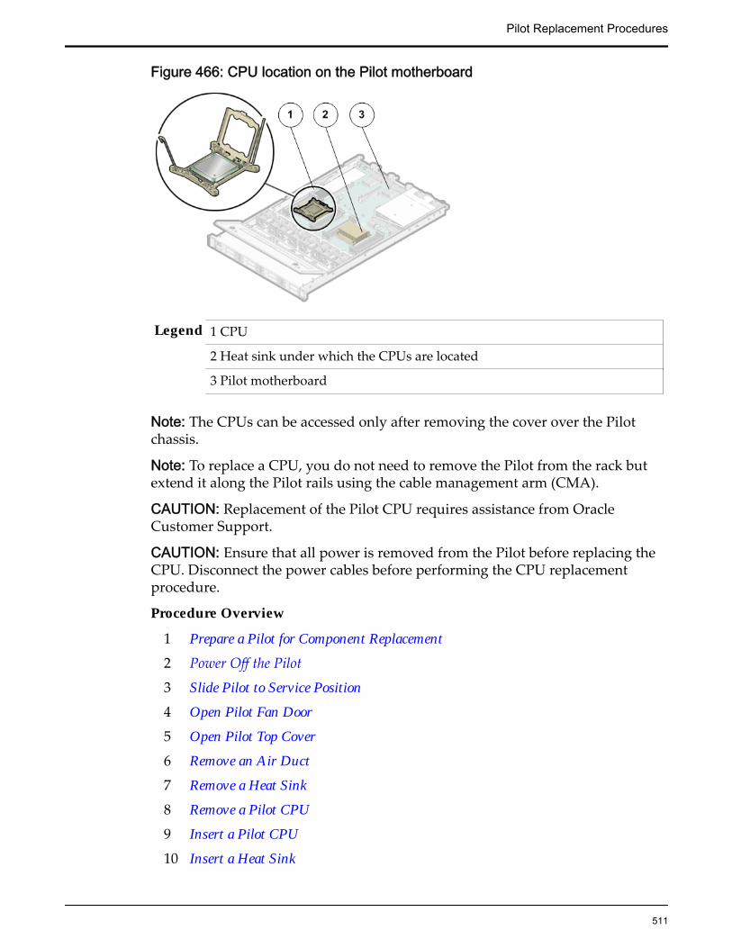
Figure 466: CPU location on the Pilot motherboard
Legend 1 CPU
2 Heat sink under which the CPUs are located
3 Pilot motherboard
Note: The CPUs can be accessed only after removing the cover over the Pilotchassis.
Note: To replace a CPU, you do not need to remove the Pilot from the rack butextend it along the Pilot rails using the cable management arm (CMA).
CAUTION: Replacement of the Pilot CPU requires assistance from OracleCustomer Support.
CAUTION: Ensure that all power is removed from the Pilot before replacing theCPU. Disconnect the power cables before performing the CPU replacementprocedure.
Procedure Overview
1 Prepare a Pilot for Component Replacement
2 Power Off the Pilot
3 Slide Pilot to Service Position
4 Open Pilot Fan Door
5 Open Pilot Top Cover
6 Remove an Air Duct
7 Remove a Heat Sink
8 Remove a Pilot CPU
9 Insert a Pilot CPU
10 Insert a Heat Sink
Pilot Replacement Procedures
511

11 Insert an Air Duct
12 Close Pilot Top Cover
13 Close Pilot Fan Door
14 Slide Pilot to Rack Position
15 Connect Power Cords On the Pilot
16 Verify Component Replacement on the Active Pilot
17 Verify Component Replacement on the Standby Pilot
Prepare a Pilot for Component Replacement1 Contact Oracle Customer Support prior to replacing a Pilot component.
Oracle Customer Support identifies the failed component on the Pilot foryou.
2 From Oracle FS System Manager (GUI), navigate to System > Hardware >Pilots and select the Pilot that contains the component that you want toreplace.
3 Select Actions > Repair Pilot.Guided Maintenance displays the list of Pilot components.
4 Based on the information from your Oracle Customer Supportrepresentative, select the correct component from the list.
5 Click Next.Guided Maintenance sends a request to flash the LEDs on the Pilot to helpyou locate the Pilot in the data center.
6 Click Next.
Guided Maintenance displays a link to Pilot Repair Procedures.
7 Click the Pilot Repair Procedures link to open and print the procedures.
8 Click Next.
• If you are replacing a component located on the active Pilot, GuidedMaintenance takes the active Pilot offline and fails over to thestandby Pilot. After the active Pilot is offline, the GUI closes. Youmay now safely disconnect the power cords.
• If you are replacing a component located on the standby Pilot,Guided Maintenance takes the standby Pilot offline. After thestandby Pilot is offline, you may safely disconnect the power cordsand data cables. When servicing the standby Pilot, failover is notrequired.
• If you are replacing a power supply, you are not required to bringthe Pilot offline. The power supplies are hot-serviceable. The powersupplies are the only Pilot components that do not require the Pilotto be brought offline. You can replace one power supply without
Pilot Replacement Procedures
512
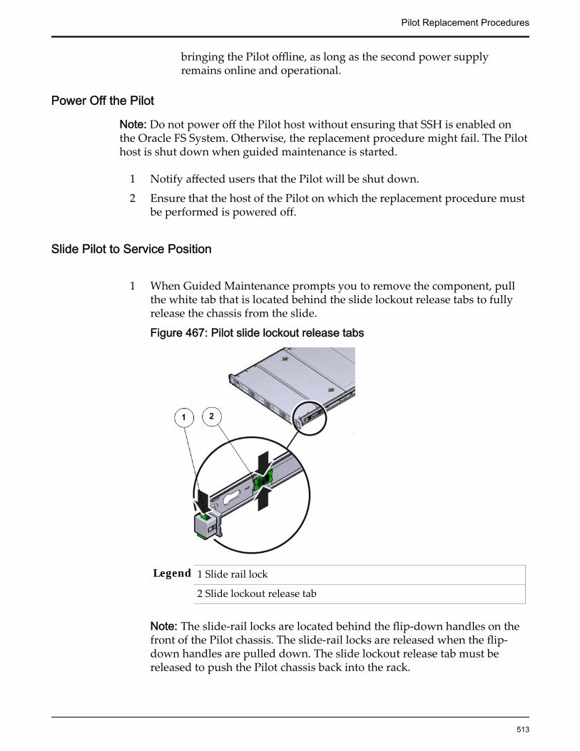
bringing the Pilot offline, as long as the second power supplyremains online and operational.
Power Off the Pilot
Note: Do not power off the Pilot host without ensuring that SSH is enabled onthe Oracle FS System. Otherwise, the replacement procedure might fail. The Pilothost is shut down when guided maintenance is started.
1 Notify affected users that the Pilot will be shut down.
2 Ensure that the host of the Pilot on which the replacement procedure mustbe performed is powered off.
Slide Pilot to Service Position
1 When Guided Maintenance prompts you to remove the component, pullthe white tab that is located behind the slide lockout release tabs to fullyrelease the chassis from the slide.
Figure 467: Pilot slide lockout release tabs
Legend 1 Slide rail lock
2 Slide lockout release tab
Note: The slide-rail locks are located behind the flip-down handles on thefront of the Pilot chassis. The slide-rail locks are released when the flip-down handles are pulled down. The slide lockout release tab must bereleased to push the Pilot chassis back into the rack.
Pilot Replacement Procedures
513

Important: Before sliding out the Pilot, ensure that the cables do notinterfere with the movement of the Pilot. Although the cable managementarm (CMA) is hinged to accommodate extending the Pilot, ensure that allcables and cords are capable of being extended.
2 Slide the Pilot chassis fully forward until the slide rails lock into position.
Figure 468: Pilot position during component replacement
Legend 1 Rack
2 Pilot chassis
3 Pilot rails
CAUTION: Deploy any rack anti-tilt mechanism before releasing therelease buttons and extending the Pilot.
Open Pilot Fan Door
Press the two fan door release tabs simultaneously forward and swing thePilot fan door to the open position.
Note: Servicing the Pilot fan modules and other components located in thefront of the Pilot, such as the front indication module (FIM) and the diskbackplanes, require that the fan door be opened. It is also easier to removethe Pilot’s top cover if you open the fan door first.
Pilot Replacement Procedures
514

Figure 469: Pilot with fan door open
Legend 1 Fan door release tabs
2 Pilot fan door in open position
Open Pilot Top Cover
1 Press down on the push button on the Pilot top cover to release the topcover and use the recessed areas to slide the top cover toward the back ofthe Pilot about 0.5 inches (12.7 mm).
Tip: Slide out the Pilot top cover by pressing down on the grooves locatedon both sides of the cover.
Figure 470: Pilot top cover removal
Legend 1 Push button to release top cover
2 Grooves to slide out top cover
2 Lift the cover off the Pilot chassis and set it aside.
Remove an Air Duct
Remove the section of the air duct that blocks access to the heat sink byapplying a slight pressure at the edge of the air duct.
Pilot Replacement Procedures
515
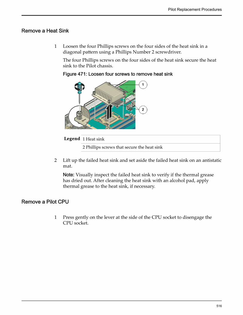
Remove a Heat Sink
1 Loosen the four Phillips screws on the four sides of the heat sink in adiagonal pattern using a Phillips Number 2 screwdriver.
The four Phillips screws on the four sides of the heat sink secure the heatsink to the Pilot chassis.
Figure 471: Loosen four screws to remove heat sink
Legend 1 Heat sink
2 Phillips screws that secure the heat sink
2 Lift up the failed heat sink and set aside the failed heat sink on an antistaticmat.
Note: Visually inspect the failed heat sink to verify if the thermal greasehas dried out. After cleaning the heat sink with an alcohol pad, applythermal grease to the heat sink, if necessary.
Remove a Pilot CPU
1 Press gently on the lever at the side of the CPU socket to disengage theCPU socket.
Pilot Replacement Procedures
516
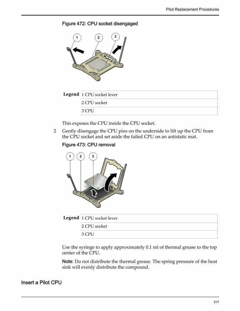
Figure 472: CPU socket disengaged
Legend 1 CPU socket lever
2 CPU socket
3 CPU
This exposes the CPU inside the CPU socket.2 Gently disengage the CPU pins on the underside to lift up the CPU from
the CPU socket and set aside the failed CPU on an antistatic mat.
Figure 473: CPU removal
Legend 1 CPU socket lever
2 CPU socket
3 CPU
Use the syringe to apply approximately 0.1 ml of thermal grease to the topcenter of the CPU.
Note: Do not distribute the thermal grease. The spring pressure of the heatsink will evenly distribute the compound.
Insert a Pilot CPU
Pilot Replacement Procedures
517

1 Unpack the component from its shipping carton.
Note: Place the component on an antistatic mat if it must be set aside forany reason.
2 Gently align the pins on the underside of the CPU to the CPU socket andpush down to secure the CPU in the socket.
Figure 474: CPU insertion
Legend 1 CPU socket lever
2 CPU socket
3 CPU
3 Push down on the lever of the CPU socket to secure the CPU inside.
Insert a Heat Sink
Secure the heat sink over the CPU to the Pilot motherboard by insertingthe four screws on the four sides of the heat sink and tightening themusing a Phillips Number 2 screwdriver.
Figure 475: Heat sink insertion
Legend 1 Heat sink
Pilot Replacement Procedures
518

2 Phillips screws that secure the heat sink
Important: Ensure that the heat sink and the screws are aligned so that theairflow marker on the heat sink faces the back of the Pilot and the systemfront marker on the heat sink faces the front of the Pilot. Also, ensure thatthe screws on opposite ends of the heat sink are tightened first. A slightforce must be applied to push down the screwdriver while tightening thescrews to overcome the tension generated.
Insert an Air Duct
Replace the section of the air duct that had been removed earlier and snapit firmly into position by applying a slight pressure at the edge of the airduct.
Note: Listen for an audible click to ensure that the air duct has been firmlyinstalled in position.
Close Pilot Top Cover
1 Place the top cover of the Pilot onto the chassis.
Tip: Place the top cover down so that it hangs over the back of the Pilot byabout 13 mm (0.5 inches) [1] and the side latches align with the slots in thesides of the Pilot chassis.
Note: There are three latching tabs on the sides of the Pilot top cover, twoon the right side and one on the left side when viewing the Pilot from thefront. There is also a latch on the underside of the top cover in the front leftcorner near the release button.
2 Check both sides of the Pilot chassis to ensure that the four corners of thetop cover are fully down and flush with the chassis.
Note: If the cover corners are not flush with the Pilot chassis, slide thecover towards the back of the chassis until you can position the covercorrectly.
Note: If the top cover is not correctly positioned before attempting to slidethe cover forward, the internal latch that is on the underside of the covermight be damaged.
3 Gently slide the top cover along the grooves of the Pilot by pressing downon either side of the top cover until it locks into place and you hear anaudible click.
Pilot Replacement Procedures
519

Figure 476: Pilot top cover installed
Legend 1 Top cover
2 Grooves to slide the top cover
3 Fan door
Close Pilot Fan Door
Close the Pilot fan door by pressing the two release tabs on both sides ofthe fan door until it locks into place.
Note: Close the Pilot fan door within 60 seconds to maintain adequateairflow to properly cool the Pilot. Leaving the door open for more than 60seconds, while the Pilot is running, might cause the Pilot to overheat andshut down. However, if power to the Pilot is switched off during thecomponent replacement procedure, the fan door can be left open.
Slide Pilot to Rack Position
1 Simultaneously pull and hold the two release tabs, one on each side of thePilot, toward the front of the Pilot while you push the Pilot into the rack.
Pilot Replacement Procedures
520

Figure 477: Location of the Pilot release tabs
Note: As you push the Pilot into the rack, verify that the cable managementarm (CMA) retracts without binding.
Note: To pull the Pilot release tab, place your finger in the center of the tab,not on the end, and apply pressure as you pull the tab toward the front ofthe Pilot.
2 Continue pushing the Pilot into the rack until the slide-rail locks on thefront of the Pilot engage the slide-rail assemblies.
Note: The Pilot locks into the rack position with an audible click.
Connect Power Cords On the Pilot
Reconnect the power cords to the Pilot.
Note: After the power cords are connected, the green SP LED and the OKLED both start to blink.
Note: Do not turn on the power to the Pilot host immediately. The poweron the Pilot host is turned on only after updating the Pilot BIOS. Turningon the power to the Pilot host early can prevent the Pilot from booting afterthe Pilot BIOS is updated.
Verify Component Replacement on the Active PilotIf you replaced a component on the active Pilot, complete the following steps toverify the status of the Pilot:
1 Restart Oracle FS System Manager (GUI).
2 Navigate to System > Hardware > Pilots.
The GUI displays the Pilot Overview page.
3 From the Pilot Overview page, review the status of the Pilot.A status of Normal requires no action.
Pilot Replacement Procedures
521

Verify Component Replacement on the Standby PilotIf you replaced a component on the standby Pilot, complete the following stepsto verify the status of the Pilot:
1 Return to Guided Maintenance and click Finish.
Guided Maintenance closes and the GUI displays the Pilot Overview page.
2 From the Pilot Overview page, review the status of the Pilot.A status of Normal requires no action.
Replace a Pilot MotherboardThe motherboard is the primary circuit board of the Pilot. All Pilot componentsare connected to the motherboard using electrical circuits and communicate withthe motherboard to ensure normal Pilot operation. Damaged ports or circuitrymight cause the motherboard to fail. A failed motherboard will cause the Pilot tofail and must be replaced as soon as possible.
Prerequisites: • Before handling a component, touch a groundedsurface to discharge any static electricity.
• Attach an electrostatic discharge (ESD) wrist strap toyour wrist, and stand on an ESD mat while replacingcomponents.
• Ensure that you have a Phillips Number 2screwdriver with at least a four-inch shaft.
• Ensure that secure shell (SSH) is enabled on theOracle FS System.
• Make sure that you have a Torx Number 10screwdriver.
• Ensure that there is a workbench available to placethe motherboard once it is removed from the rack forservicing.
• Fail over the Pilot before replacing the componentusing Guided Maintenance.
Note: The Pilot must be failed over to prevent dataloss or data corruption during the componentreplacement process.
Each Pilot has a motherboard inside the chassis. The Pilot motherboard is a fieldreplaceable unit (FRU) and is not hot-swappable. Replacing a motherboardrequires you to power down the Pilot. The following figure shows the location ofthe Pilot motherboard inside the chassis.
Pilot Replacement Procedures
522
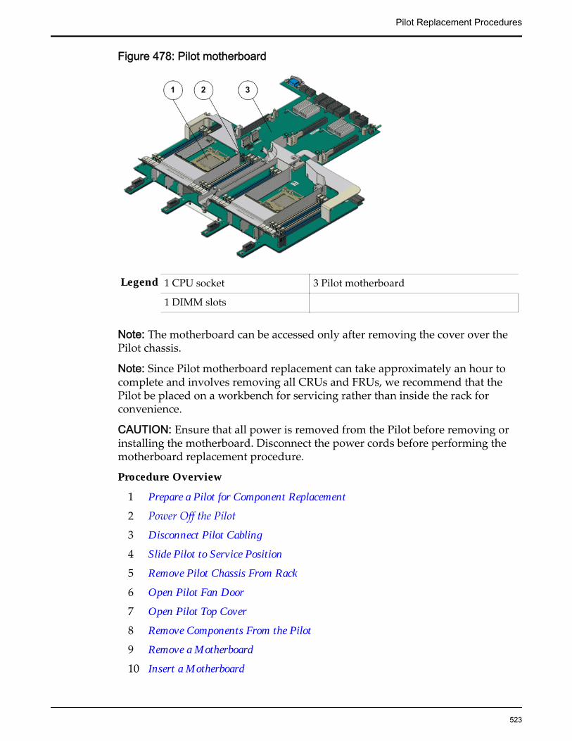
Figure 478: Pilot motherboard
Legend 1 CPU socket 3 Pilot motherboard
1 DIMM slots
Note: The motherboard can be accessed only after removing the cover over thePilot chassis.
Note: Since Pilot motherboard replacement can take approximately an hour tocomplete and involves removing all CRUs and FRUs, we recommend that thePilot be placed on a workbench for servicing rather than inside the rack forconvenience.
CAUTION: Ensure that all power is removed from the Pilot before removing orinstalling the motherboard. Disconnect the power cords before performing themotherboard replacement procedure.
Procedure Overview
1 Prepare a Pilot for Component Replacement
2 Power Off the Pilot
3 Disconnect Pilot Cabling
4 Slide Pilot to Service Position
5 Remove Pilot Chassis From Rack
6 Open Pilot Fan Door
7 Open Pilot Top Cover
8 Remove Components From the Pilot
9 Remove a Motherboard
10 Insert a Motherboard
Pilot Replacement Procedures
523

11 Insert Components on the Pilot
12 Close Pilot Top Cover
13 Close Pilot Fan Door
14 Insert the Pilot Onto the Rack
15 Update the Pilot BIOS
Prepare a Pilot for Component Replacement1 Contact Oracle Customer Support prior to replacing a Pilot component.
Oracle Customer Support identifies the failed component on the Pilot foryou.
2 From Oracle FS System Manager (GUI), navigate to System > Hardware >Pilots and select the Pilot that contains the component that you want toreplace.
3 Select Actions > Repair Pilot.Guided Maintenance displays the list of Pilot components.
4 Based on the information from your Oracle Customer Supportrepresentative, select the correct component from the list.
5 Click Next.Guided Maintenance sends a request to flash the LEDs on the Pilot to helpyou locate the Pilot in the data center.
6 Click Next.
Guided Maintenance displays a link to Pilot Repair Procedures.
7 Click the Pilot Repair Procedures link to open and print the procedures.
8 Click Next.
• If you are replacing a component located on the active Pilot, GuidedMaintenance takes the active Pilot offline and fails over to thestandby Pilot. After the active Pilot is offline, the GUI closes. Youmay now safely disconnect the power cords.
• If you are replacing a component located on the standby Pilot,Guided Maintenance takes the standby Pilot offline. After thestandby Pilot is offline, you may safely disconnect the power cordsand data cables. When servicing the standby Pilot, failover is notrequired.
• If you are replacing a power supply, you are not required to bringthe Pilot offline. The power supplies are hot-serviceable. The powersupplies are the only Pilot components that do not require the Pilotto be brought offline. You can replace one power supply withoutbringing the Pilot offline, as long as the second power supplyremains online and operational.
Pilot Replacement Procedures
524
Power Off the Pilot
Note: Do not power off the Pilot host without ensuring that SSH is enabled onthe Oracle FS System. Otherwise, the replacement procedure might fail. The Pilothost is shut down when Guided Maintenance is started.
1 Notify affected users that the Pilot will be shut down.
2 Ensure that the host of the Pilot on which the replacement procedure mustbe performed is powered off.
Disconnect Pilot Cabling
1 Disconnect all power and data cables from the Pilot.These include:
• Ethernet cables connected to the network ports
• Rollover cable connected to the serial port
• Power cables connected to the power supplies of the Pilot
Note: Oracle Customer Support recommends labeling all cables connectedto the Pilot so that they can be re-connected accurately to the Pilot after thereplacement procedure is complete.
Important: Ensure that the Pilot host is powered off completely beforeremoving the power cords.
CAUTION: When you press the power button to enter standby powermode, power is still directed to the power supply fans in the Pilot. Tocompletely power off the Pilot, you must disconnect the power cords fromthe back of the power supplies.
2 Disconnect the cable management arm (CMA) by pulling the release tabson the left side until the CMA detaches from the chassis.
Note: Do not disconnect the cables attached to the CMA.
Pilot Replacement Procedures
525

Figure 479: CMA release tabs
Legend 1 CMA 4 Release tab to disconnect the CMA
2 Pilot 5 Cables disconnected from the Pilot
3 Rails
Slide Pilot to Service Position
1 When Guided Maintenance prompts you to remove the component, pullthe white tab that is located behind the slide lockout release tabs to fullyrelease the chassis from the slide.
Pilot Replacement Procedures
526

Figure 480: Pilot slide lockout release tabs
Legend 1 Slide rail lock
2 Slide lockout release tab
Note: The slide-rail locks are located behind the flip-down handles on thefront of the Pilot chassis. The slide-rail locks are released when the flip-down handles are pulled down. The slide lockout release tab must bereleased to push the Pilot chassis back into the rack.
Important: Before sliding out the Pilot, ensure that the cables do notinterfere with the movement of the Pilot. Although the cable managementarm (CMA) is hinged to accommodate extending the Pilot, ensure that allcables and cords are capable of being extended.
2 Slide the Pilot chassis fully forward until the slide rails lock into position.
Pilot Replacement Procedures
527

Figure 481: Pilot position during component replacement
Legend 1 Rack
2 Pilot chassis
3 Pilot rails
CAUTION: Deploy any rack anti-tilt mechanism before releasing therelease buttons and extending the Pilot.
Remove Pilot Chassis From Rack
1 From the front of the Pilot, pull the slide-rail release tabs toward the frontof the Pilot and pull the Pilot out of the rack until it is free of the rack rails.
Note: A slide-rail release tab is located on each slide-rail. To pull the slide-rail release tab, place your finger in the center of the tab, not on the end,and apply pressure as you pull the tab toward the front of the Pilot.
2 With the help of a partner or a mechanical lift, place the Pilot on anantistatic surface or ESD qualified mat or workbench.
CAUTION: Deploy any rack anti-tilt mechanisms before installing the Pilotinto the rack.
CAUTION: The Pilot weighs approximately 39.9 pounds (18.1 kilograms).Two people are required to dismount and carry the chassis.
Pilot Replacement Procedures
528

CAUTION: Do not use the power supply handles to lift the chassis. Usingthe power supply handles to lift the chassis can damage the powersupplies and disrupt electrical power to the Pilot.
Open Pilot Fan Door
Press the two fan door release tabs simultaneously forward and swing thePilot fan door to the open position.
Note: Servicing the Pilot fan modules and other components located in thefront of the Pilot, such as the front indication module (FIM) and the diskbackplanes, require that the fan door be opened. It is also easier to removethe Pilot’s top cover if you open the fan door first.
Figure 482: Pilot with fan door open
Legend 1 Fan door release tabs
2 Pilot fan door in open position
Open Pilot Top Cover
1 Press down on the push button on the Pilot top cover to release the topcover and use the recessed areas to slide the top cover toward the back ofthe Pilot about 0.5 inches (12.7 mm).
Tip: Slide out the Pilot top cover by pressing down on the grooves locatedon both sides of the cover.
Pilot Replacement Procedures
529

Figure 483: Pilot top cover removal
Legend 1 Push button to release top cover
2 Grooves to slide out top cover
2 Lift the cover off the Pilot chassis and set it aside.
Remove Components From the Pilot
Remove the necessary components on the Pilot following the proceduresoutlined below.
Note: All components that are removed from the Pilot must be placed onan antistatic surface or ESD qualified mat.
Remove a Power Supply
1 From the back of the Pilot, remove the velcro that holds the power cordfrom the failed power supply.
Note: You might need to swing the cable management arm (CMA) out ofthe way to access the power supplies. If the CMA is still in the way, extendthe Pilot approximately 20 cm (8 inches) out of the front of the rack.
Note: The fans of a failed power supply may still be spinning when thesystem is powered on. You can remove a power supply while the fans arestill spinning.
2 Disconnect the power cord from the failed power supply.
3 While holding the power supply handle with one hand, use the other handto push the power supply latch to the left.
Pilot Replacement Procedures
530

Figure 484: Power supply removal
Legend 1 Power supplies (PS0 and PS1)
2 Power supply handle
3 Power supply compartment
4 Pull the power supply out of the chassis and place the power supply on anantistatic mat.
CAUTION: Whenever you remove a power supply, you should replace itwith another power supply; otherwise, the Pilot might overheat due toimproper airflow.
Remove a Fan Module
1 Using your thumb and forefinger on both sides of the fan module tab,gently lift the fan module from the fan compartment.
Pilot Replacement Procedures
531

Figure 485: Pilot fan module removal
Legend 1 Fan module tab
2 Fan modules
3 Fan door
Note: When removing a fan module, do not rock it back and forth. Rockingthe fan module can cause damage to the motherboard connectors.
2 Set the fan module aside on an antistatic mat.
Note: When replacing a fan module, do not service any other componentsunless the system is shut down and the power cords are removed.
Remove a Pilot DIMM
1 Remove the DIMM by pressing down on the tabs on both sides of theDIMM to unlock it from the slot.
Pilot Replacement Procedures
532
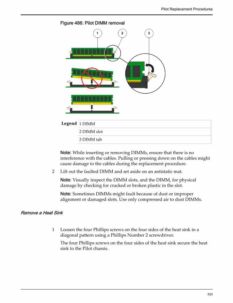
Figure 486: Pilot DIMM removal
Legend 1 DIMM
2 DIMM slot
3 DIMM tab
Note: While inserting or removing DIMMs, ensure that there is nointerference with the cables. Pulling or pressing down on the cables mightcause damage to the cables during the replacement procedure.
2 Lift out the faulted DIMM and set aside on an antistatic mat.
Note: Visually inspect the DIMM slots, and the DIMM, for physicaldamage by checking for cracked or broken plastic in the slot.
Note: Sometimes DIMMs might fault because of dust or improperalignment or damaged slots. Use only compressed air to dust DIMMs.
Remove a Heat Sink
1 Loosen the four Phillips screws on the four sides of the heat sink in adiagonal pattern using a Phillips Number 2 screwdriver.
The four Phillips screws on the four sides of the heat sink secure the heatsink to the Pilot chassis.
Pilot Replacement Procedures
533
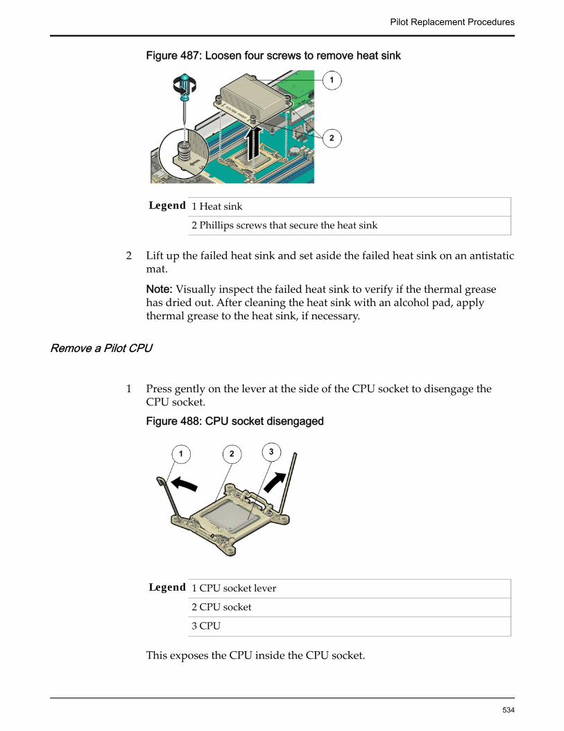
Figure 487: Loosen four screws to remove heat sink
Legend 1 Heat sink
2 Phillips screws that secure the heat sink
2 Lift up the failed heat sink and set aside the failed heat sink on an antistaticmat.
Note: Visually inspect the failed heat sink to verify if the thermal greasehas dried out. After cleaning the heat sink with an alcohol pad, applythermal grease to the heat sink, if necessary.
Remove a Pilot CPU
1 Press gently on the lever at the side of the CPU socket to disengage theCPU socket.
Figure 488: CPU socket disengaged
Legend 1 CPU socket lever
2 CPU socket
3 CPU
This exposes the CPU inside the CPU socket.
Pilot Replacement Procedures
534
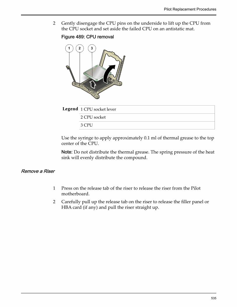
2 Gently disengage the CPU pins on the underside to lift up the CPU fromthe CPU socket and set aside the failed CPU on an antistatic mat.
Figure 489: CPU removal
Legend 1 CPU socket lever
2 CPU socket
3 CPU
Use the syringe to apply approximately 0.1 ml of thermal grease to the topcenter of the CPU.
Note: Do not distribute the thermal grease. The spring pressure of the heatsink will evenly distribute the compound.
Remove a Riser
1 Press on the release tab of the riser to release the riser from the Pilotmotherboard.
2 Carefully pull up the release tab on the riser to release the filler panel orHBA card (if any) and pull the riser straight up.
Pilot Replacement Procedures
535
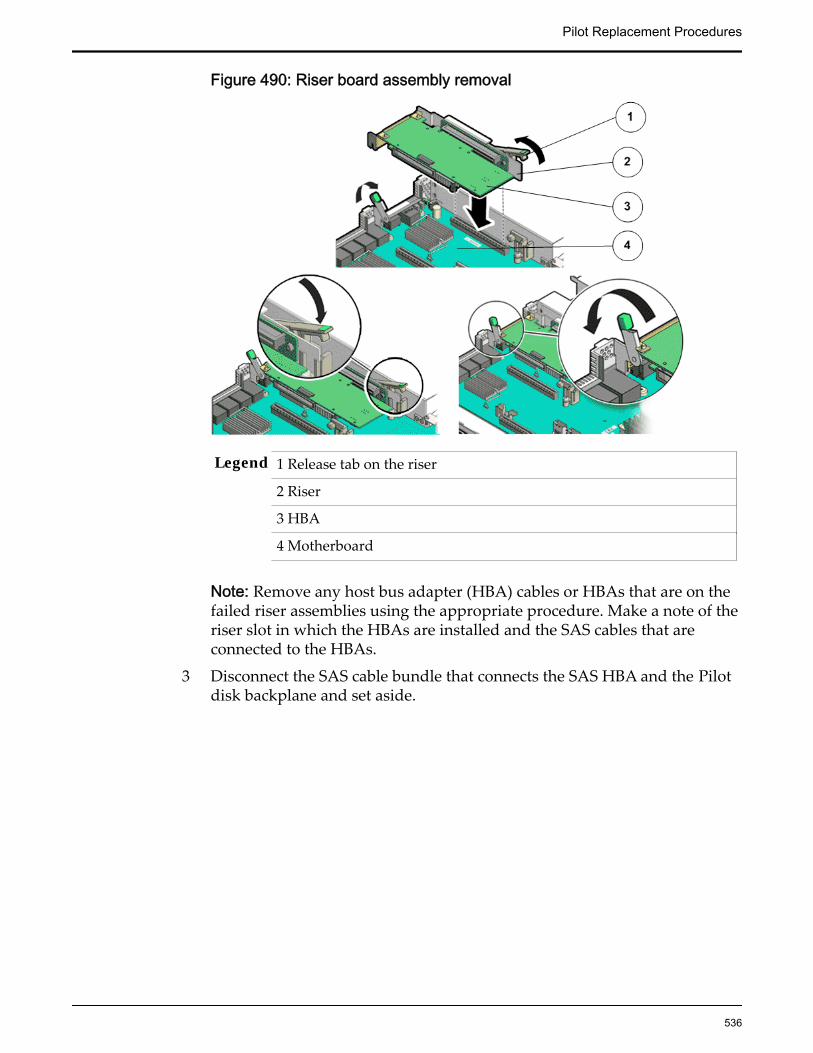
Figure 490: Riser board assembly removal
Legend 1 Release tab on the riser
2 Riser
3 HBA
4 Motherboard
Note: Remove any host bus adapter (HBA) cables or HBAs that are on thefailed riser assemblies using the appropriate procedure. Make a note of theriser slot in which the HBAs are installed and the SAS cables that areconnected to the HBAs.
3 Disconnect the SAS cable bundle that connects the SAS HBA and the Pilotdisk backplane and set aside.
Pilot Replacement Procedures
536

Figure 491: Disconnect SAS cable bundle
Legend 1 Riser
2 HBA
3 SAS cable bundle
4 Remove any HBA cards (usually the SAS card) that are inserted into thePCI-express (PCI-e) slots of the riser and place the riser and the HBA cardson an antistatic mat.
Note: Retain the HBA cards because they will be placed inside thereplacement riser board assembly.
Remove a Motherboard
1 Disconnect the disk backplane power cable, LED cable, and front indicatormodule (FIM) cable from the motherboard.
2 Carefully disconnect the SAS cable bundle that you disconnected from theSAS HBA out of the cable trough.
Pilot Replacement Procedures
537

Figure 492: Motherboard removal
Legend 1 FIM cable 4 Captive screws
2 LED cable 5 Pilot motherboard
3 SAS cable bundle
3 Loosen the four captive screws that secure the Pilot mid-wall to the Pilotchassis.
4 Lift the Pilot mid-wall slightly up and toward the front of the Pilot todisengage it from the mushroom standoffs that are located one on each endof the Pilot chassis mid-wall.
5 Place the mid-wall and the SAS cable bundle towards the front of the Pilotout of the way of the motherboard.
6 Grasp the middle of the air deflector in the front and back and slide themotherboard towards the front of the Pilot and lift it slightly to disengagethe six mushroom standoffs that are located on the Pilot’s chassis under themotherboard.
Insert a Motherboard
Pilot Replacement Procedures
538

1 Unpack the component from its shipping carton.
Note: Place the component on an antistatic mat if it must be set aside forany reason.
2 Insert the motherboard into the Pilot by grasping the middle of the airdeflector in the front and back and tilting the front of the motherboard upslightly and pushing it into the opening in the rear of the Pilot chassis.
Figure 493: Pilot motherboard insertion
Legend 1 Pilot motherboard 4 LED cable
2 Captive screws that secure motherboard 5 FIM cable
3 SAS cable bundle
3 Lower the motherboard into the Pilot chassis and slide it to the back until itengages the six standoffs located on the Pilot’s chassis under themotherboard.
4 Install the Pilot mid-wall to the Pilot chassis by tightening the four captivescrews.Ensure that the indicators, connectors, and controls at the rear of themotherboard fit correctly into the back of the Pilot chassis.
Pilot Replacement Procedures
539
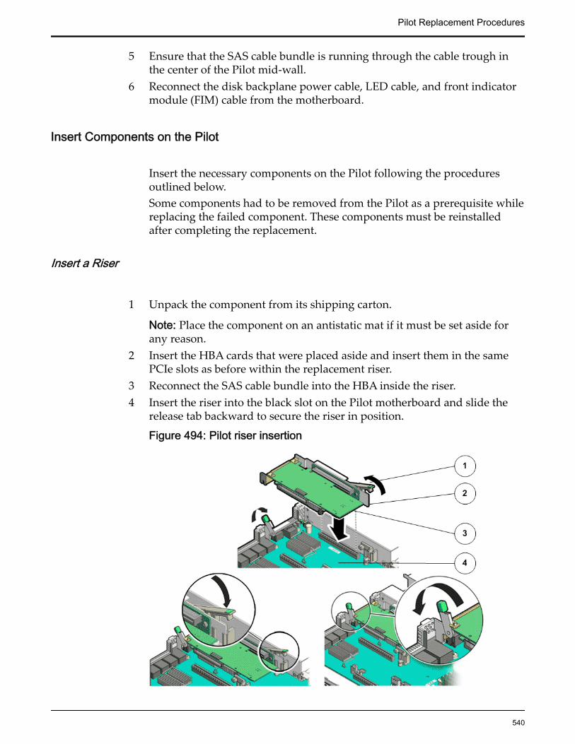
5 Ensure that the SAS cable bundle is running through the cable trough inthe center of the Pilot mid-wall.
6 Reconnect the disk backplane power cable, LED cable, and front indicatormodule (FIM) cable from the motherboard.
Insert Components on the Pilot
Insert the necessary components on the Pilot following the proceduresoutlined below.Some components had to be removed from the Pilot as a prerequisite whilereplacing the failed component. These components must be reinstalledafter completing the replacement.
Insert a Riser
1 Unpack the component from its shipping carton.
Note: Place the component on an antistatic mat if it must be set aside forany reason.
2 Insert the HBA cards that were placed aside and insert them in the samePCIe slots as before within the replacement riser.
3 Reconnect the SAS cable bundle into the HBA inside the riser.4 Insert the riser into the black slot on the Pilot motherboard and slide the
release tab backward to secure the riser in position.
Figure 494: Pilot riser insertion
Pilot Replacement Procedures
540

Legend 1 Release tab
2 Riser
3 HBA
4Pilot motherboard
5 Insert the filler panels, if any, inside the riser.
Insert a Pilot CPU
1 Unpack the component from its shipping carton.
Note: Place the component on an antistatic mat if it must be set aside forany reason.
2 Gently align the pins on the underside of the CPU to the CPU socket andpush down to secure the CPU in the socket.
Figure 495: CPU insertion
Legend 1 CPU socket lever
2 CPU socket
3 CPU
3 Push down on the lever of the CPU socket to secure the CPU inside.
Insert a Heat Sink
Secure the heat sink over the CPU to the Pilot motherboard by insertingthe four screws on the four sides of the heat sink and tightening themusing a Phillips Number 2 screwdriver.
Pilot Replacement Procedures
541

Figure 496: Heat sink insertion
Legend 1 Heat sink
2 Phillips screws that secure the heat sink
Important: Ensure that the heat sink and the screws are aligned so that theairflow marker on the heat sink faces the back of the Pilot and the systemfront marker on the heat sink faces the front of the Pilot. Also, ensure thatthe screws on opposite ends of the heat sink are tightened first. A slightforce must be applied to push down the screwdriver while tightening thescrews to overcome the tension generated.
Insert a Pilot DIMM
1 Unpack the component from its shipping carton.
Note: Place the component on an antistatic mat if it must be set aside forany reason.
2 Press the DIMM fully into the DIMM slot and ensure that the tabs on bothsides of the DIMM are locked.
Important: Ensure that the notch in the DIMM lines up with the key in theslot.
Note: Replace only one DIMM at a time to make sure that they are insertedinto the correct slots. Attempting to insert multiple DIMMs into the slotsmight damage the DIMMs due to excessive flexure.
Note: Never leave a DIMM slot unpopulated. Insert filler panels intoempty DIMM slots to ensure proper air flow inside the Pilot.
Insert a Fan Module
1 Unpack the component from its shipping carton.
Pilot Replacement Procedures
542

Note: Place the component on an antistatic mat if it must be set aside forany reason.
2 Grasp the fan module tabs and press the fan down firmly into the fanmodule compartment.
Figure 497: Fan module insertion
Legend 1 Fan module tab
2 Fan modules
3 Fan door
Note: Apply firm pressure to fully seat the fan module into the fancompartment. The fan modules are notched to ensure that they areinstalled in the correct orientation.
3 Press down on the fan module and apply firm pressure to fully seat the fanmodule.
Insert a Power Supply1 Unpack the component from its shipping carton.
Note: Place the component on an antistatic mat if it must be set aside forany reason.
2 Align the replacement power supply with the empty power supplycompartment.
3 Slide the power supply into the bay until it is fully seated.
Pilot Replacement Procedures
543
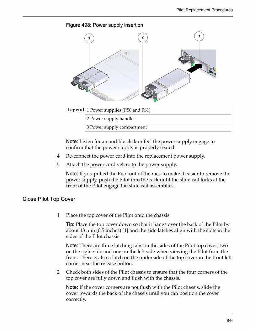
Figure 498: Power supply insertion
Legend 1 Power supplies (PS0 and PS1)
2 Power supply handle
3 Power supply compartment
Note: Listen for an audible click or feel the power supply engage toconfirm that the power supply is properly seated.
4 Re-connect the power cord into the replacement power supply.
5 Attach the power cord velcro to the power supply.
Note: If you pulled the Pilot out of the rack to make it easier to remove thepower supply, push the Pilot into the rack until the slide-rail locks at thefront of the Pilot engage the slide-rail assemblies.
Close Pilot Top Cover
1 Place the top cover of the Pilot onto the chassis.
Tip: Place the top cover down so that it hangs over the back of the Pilot byabout 13 mm (0.5 inches) [1] and the side latches align with the slots in thesides of the Pilot chassis.
Note: There are three latching tabs on the sides of the Pilot top cover, twoon the right side and one on the left side when viewing the Pilot from thefront. There is also a latch on the underside of the top cover in the front leftcorner near the release button.
2 Check both sides of the Pilot chassis to ensure that the four corners of thetop cover are fully down and flush with the chassis.
Note: If the cover corners are not flush with the Pilot chassis, slide thecover towards the back of the chassis until you can position the covercorrectly.
Pilot Replacement Procedures
544
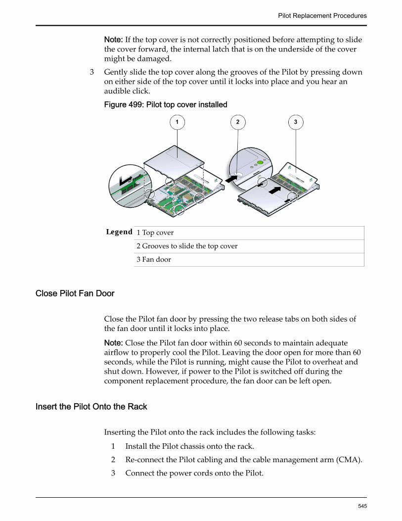
Note: If the top cover is not correctly positioned before attempting to slidethe cover forward, the internal latch that is on the underside of the covermight be damaged.
3 Gently slide the top cover along the grooves of the Pilot by pressing downon either side of the top cover until it locks into place and you hear anaudible click.
Figure 499: Pilot top cover installed
Legend 1 Top cover
2 Grooves to slide the top cover
3 Fan door
Close Pilot Fan Door
Close the Pilot fan door by pressing the two release tabs on both sides ofthe fan door until it locks into place.
Note: Close the Pilot fan door within 60 seconds to maintain adequateairflow to properly cool the Pilot. Leaving the door open for more than 60seconds, while the Pilot is running, might cause the Pilot to overheat andshut down. However, if power to the Pilot is switched off during thecomponent replacement procedure, the fan door can be left open.
Insert the Pilot Onto the Rack
Inserting the Pilot onto the rack includes the following tasks:
1 Install the Pilot chassis onto the rack.
2 Re-connect the Pilot cabling and the cable management arm (CMA).
3 Connect the power cords onto the Pilot.
Pilot Replacement Procedures
545

4 Slide the Pilot into rack position.
5 Update the Pilot BIOS.
6 Power on the Pilot host.
7 Verify the Pilot component status.
Slide Pilot to Rack Position
1 Simultaneously pull and hold the two release tabs, one on each side of thePilot, toward the front of the Pilot while you push the Pilot into the rack.
Figure 500: Location of the Pilot release tabs
Note: As you push the Pilot into the rack, verify that the cable managementarm (CMA) retracts without binding.
Note: To pull the Pilot release tab, place your finger in the center of the tab,not on the end, and apply pressure as you pull the tab toward the front ofthe Pilot.
2 Continue pushing the Pilot into the rack until the slide-rail locks on thefront of the Pilot engage the slide-rail assemblies.
Note: The Pilot locks into the rack position with an audible click.
Re-connect Pilot Cabling
1 Reconnect the following cables that had been disconnected from the Pilot.
• Ethernet cables connected to the network ports
• Rollover cable connected to the serial port
Note: If the cable management arm (CMA) is in the way, extend the Pilotapproximately 13 cm (5 inches) out of the front of the rack. Once the cables
Pilot Replacement Procedures
546
are connected to the ports, the Pilot can be pushed back into the rackposition.
2 Reconnect the power cords to the power supplies and secure them with thevelcro straps.
3 If necessary, reinstall the cables into the cable management arm (CMA) andsecure them with cable straps.
4 Reconnect the CMA to the Pilot chassis by reattaching the release tabs onboth sides of the CMA.
Connect Power Cords On the Pilot
Reconnect the power cords to the Pilot.
Note: After the power cords are connected, the green SP LED and the OKLED both start to blink.
Note: Do not turn on the power to the Pilot host immediately. The poweron the Pilot host is turned on only after updating the Pilot BIOS. Turningon the power to the Pilot host early can prevent the Pilot from booting afterthe Pilot BIOS is updated.
Update the Pilot BIOS
Update the Pilot BIOS to ensure that the latest version of the BIOS is installed onthe Pilot.
If the Pilot is not connected to the Oracle FS System, you need the followingitems to update the BIOS:
• The login credentials for the Pilot root password and the Oracle IntegratedLights Out Manager (ILOM) root password.
Pilot BIOS updates are required when a new version of the BIOS is released orwhen a Pilot motherboard is replaced. The Pilot BIOS and ILOM imageconfiguration files must be copied and installed on the Pilot with the replacementmotherboard using the buddy Pilot. Perform the Pilot BIOS update after the Pilotmotherboard has been replaced. In this procedure, the Pilot is not be connectedto the Oracle FS System.
1 Enable secure shell (SSH) on your system using the CLI.
2 Login to the Pilot.
Required credentials:
• Username: root• Password: a1s2d3f$
Pilot Replacement Procedures
547
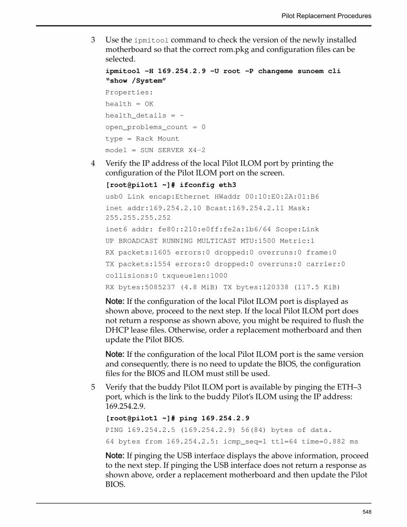
3 Use the ipmitool command to check the version of the newly installedmotherboard so that the correct rom.pkg and configuration files can beselected.ipmitool –H 169.254.2.9 –U root –P changeme sunoem cli“show /System”Properties:health = OKhealth_details = -open_problems_count = 0type = Rack Mountmodel = SUN SERVER X4-2
4 Verify the IP address of the local Pilot ILOM port by printing theconfiguration of the Pilot ILOM port on the screen.[root@pilot1 ~]# ifconfig eth3usb0 Link encap:Ethernet HWaddr 00:10:E0:2A:01:B6inet addr:169.254.2.10 Bcast:169.254.2.11 Mask:255.255.255.252inet6 addr: fe80::210:e0ff:fe2a:1b6/64 Scope:LinkUP BROADCAST RUNNING MULTICAST MTU:1500 Metric:1RX packets:1605 errors:0 dropped:0 overruns:0 frame:0TX packets:1554 errors:0 dropped:0 overruns:0 carrier:0collisions:0 txqueuelen:1000RX bytes:5085237 (4.8 MiB) TX bytes:120338 (117.5 KiB)Note: If the configuration of the local Pilot ILOM port is displayed asshown above, proceed to the next step. If the local Pilot ILOM port doesnot return a response as shown above, you might be required to flush theDHCP lease files. Otherwise, order a replacement motherboard and thenupdate the Pilot BIOS.
Note: If the configuration of the local Pilot ILOM port is the same versionand consequently, there is no need to update the BIOS, the configurationfiles for the BIOS and ILOM must still be used.
5 Verify that the buddy Pilot ILOM port is available by pinging the ETH–3port, which is the link to the buddy Pilot’s ILOM using the IP address:169.254.2.9.[root@pilot1 ~]# ping 169.254.2.9PING 169.254.2.5 (169.254.2.9) 56(84) bytes of data.64 bytes from 169.254.2.5: icmp_seq=1 ttl=64 time=0.882 msNote: If pinging the USB interface displays the above information, proceedto the next step. If pinging the USB interface does not return a response asshown above, order a replacement motherboard and then update the PilotBIOS.
Pilot Replacement Procedures
548

6 Confirm that the Pilot BIOS firmware package is located at /rpms/firmware/XXXXXXXXXand is as follows: ILOM-3_1_2_30_r82439-Sun_Server_X4-2.pkg.
The following table lists the package name section along with associateddescription:
Package name section Description
ILOM- Package specifically designed for the Oracle ILOM port
3_ First octet in the version naming scheme
1_ Second octet in the version naming scheme
2_ Third octet in the version naming scheme
30_ Fourth octet in the version naming scheme
r82439 Release version number
Sun_Server_X4-2 Make and model number of the package
7 Update the Pilot BIOS firmware and the ILOM image by executing thefollowing command on the Pilot:[root@pilot1 ~]# fwupdate update sp-bios-firmware –n sp_bios–f /rpms/firmware/ILOM-3_1_2_30_b_r86439-Sun_Server_X4-2.pkg-o=/var/log/messages –q –H=169.254.2.9 –U=rootWhen prompted for the password, enter: changeme.
Note: Compare the Pilot BIOS firmware version number with the packagelocated at /rpms/firmware/XXXXXXXXX on the Pilot. If the Pilot BIOSfirmware version on the replacement motherboard is lower, upgrade thePilot BIOS.
8 Select the XML file that matches the version of the motherboard.ubiosconfig –H 169.254.2.9 –U root import all –xy /rpms/firmware/pilot_x4-2_bios_25010603_fs1-2_defaults.xmlilomconfig import config -H 169.254.2.9 -U root -y --xmlfile=/rpms/firmware/pilot_x4-2_ilom_3.1.2.30.b_r86439_fs1-2_defaults.xmlNote: The BIOS and ILOM configuration files are found in the /rpms/firmware directory.
9 The BIOS and ILOM configuration files are found in the /rpms/firmwaredirectory. Select the XML file that matches the version of the motherboard.ubiosconfig –H 169.254.2.9 –U root import all –xy /rpms/firmware/pilot_x4-2_bios_25010603_fs1-2_defaults.xmlilomconfig import config -H 169.254.2.9 -U root -y --xmlfile=/rpms/firmware/pilot_x4-2_ilom_3.1.2.30.b_r86439_fs1-2_defaults.xml
10 Restart the Pilot to initialize the BIOS update.
Pilot Replacement Procedures
549

• If the metadata file is available and the Pilot does not restartautomatically, type y at the prompt. Do you wish toautomatically reboot now? [y/n]?
• If no metadata.xml file is available or the metadata file does notcontain the reboot instructions, reboot the Pilot manually.
Note: After updating the Pilot BIOS, power on the host of the Pilot with the newmotherboard, by pushing the Power or Reset button at the front of the Pilot.After the Pilot host boots, the green LED on the power supplies stop blinkingand become steady.
Note: Because the Pilot is not connected to the Oracle FS System during the BIOSupdate, ensure that both Pilots are synchronized after the Pilot is connected tothe Oracle FS System.
Verify Component Replacement on the Standby PilotIf you replaced a component on the standby Pilot, complete the following stepsto verify the status of the Pilot:
1 Return to Guided Maintenance and click Finish.
Guided Maintenance closes and the GUI displays the Pilot Overview page.
2 From the Pilot Overview page, review the status of the Pilot.A status of Normal requires no action.
Verify Component Replacement on the Active PilotIf you replaced a component on the active Pilot, complete the following steps toverify the status of the Pilot:
1 Restart Oracle FS System Manager (GUI).
2 Navigate to System > Hardware > Pilots.
The GUI displays the Pilot Overview page.
3 From the Pilot Overview page, review the status of the Pilot.A status of Normal requires no action.
Pilot Replacement Procedures
550

APPENDIX A
Oracle FS System LED Status
Oracle FS System LEDsAn Oracle FS System includes LEDs to indicate the status of the hardwarecomponents. To restore reliability to the Oracle FS System, locate the specificfailed component so that you can replace it. Hardware LED configuration helpsyou identify the failed component.
Important: If you cannot locate the hardware component that must be replaced,contact Oracle Customer Support.
The Guided Maintenance feature of the Oracle FS System Manager triggers thechassis with the failed component to blink, or it triggers all of the other chassis toblink, except for the one with the failed component. This blinking pattern helpsyou to identify component status.
Note: LED interpretations in this appendix apply to a system after it has beenpowered on.
Controller LED IndicatorsThe LED alarm assembly is a high-level status indicator of the Controller andController components. Use these diagnostic LEDs to determine if a componenthas failed in the Controller. The LED alarm assembly also includes a powerbutton to power on the Controller. Besides, the LED alarm assembly there is theController Identification Display (CID) that identifies the Controller by itsnumeric identifier.
The following figure shows the front display panel of the LED alarm assemblyon the Controller:
551
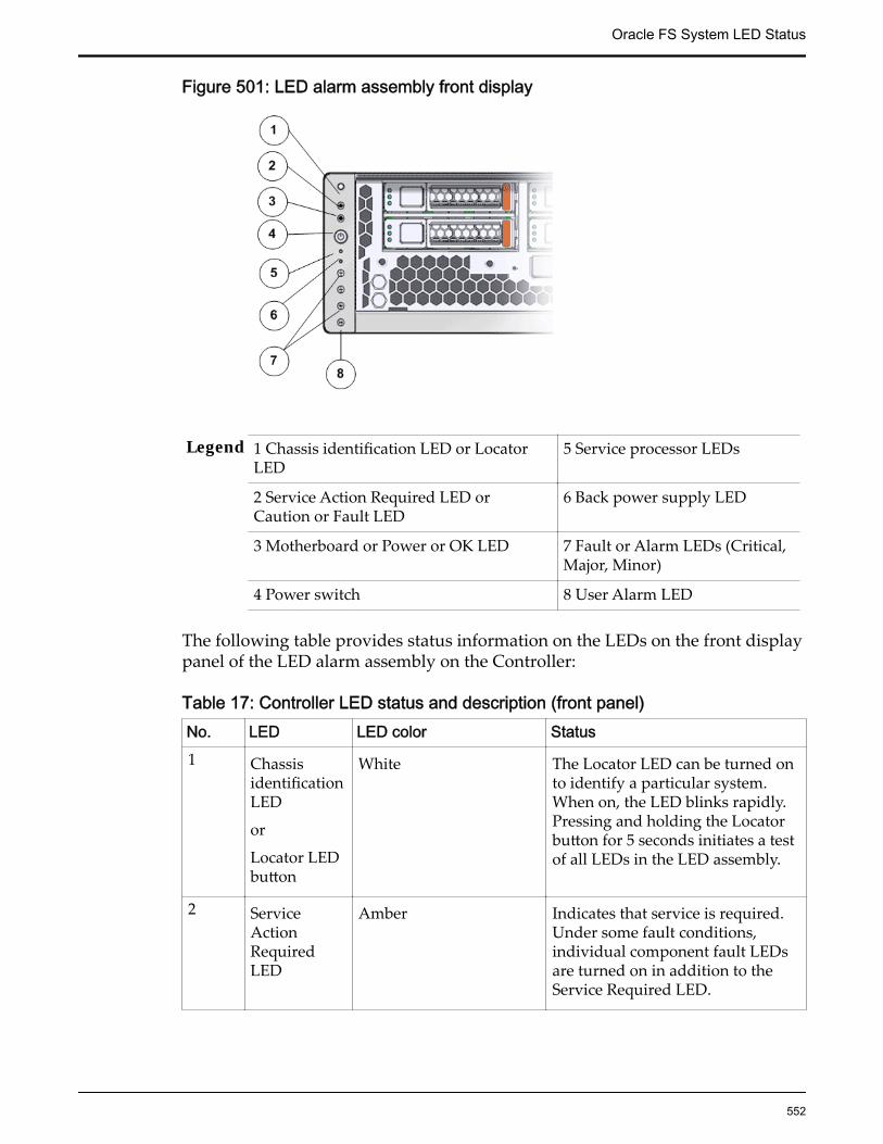
Figure 501: LED alarm assembly front display
Legend 1 Chassis identification LED or LocatorLED
5 Service processor LEDs
2 Service Action Required LED orCaution or Fault LED
6 Back power supply LED
3 Motherboard or Power or OK LED 7 Fault or Alarm LEDs (Critical,Major, Minor)
4 Power switch 8 User Alarm LED
The following table provides status information on the LEDs on the front displaypanel of the LED alarm assembly on the Controller:
Table 17: Controller LED status and description (front panel)No. LED LED color Status1 Chassis
identificationLED
or
Locator LEDbutton
White The Locator LED can be turned onto identify a particular system.When on, the LED blinks rapidly.Pressing and holding the Locatorbutton for 5 seconds initiates a testof all LEDs in the LED assembly.
2 ServiceActionRequiredLED
Amber Indicates that service is required.Under some fault conditions,individual component fault LEDsare turned on in addition to theService Required LED.
Oracle FS System LED Status
552

Table 17: Controller LED status and description (front panel) (continued)No. LED LED color Status3 Power or OK
LEDGreen Indicates these conditions:
• Off – Indicates that thesystem is not running in itsnormal state. System powermight be off. The SP mightbe running.
• Steady on – Indicates thatthe system is powered onand is running in its normaloperating state. No serviceactions are required.
• Fast blink: Indicates that thesystem is running instandby mode and can bequickly returned to fullfunction.
• Slow blink: Indicates thata normal but transitoryactivity is taking place.Slow blinking mightindicate that systemdiagnostics are runningor that the system isbooting.
5 ServiceprocessorLED
Green Indicates the state of the serviceprocessor:
• Flashing: Indicates the SPis booting.
• Steady: Indicates a steadystate, no service action isrequired.
6 Back powersupply LED
Amber Indicates the state of the powersupplies:
• Off – Indicates a steadystate, no service action isrequired.
• On – Indicates a faultwith one of the powersupplies.
Oracle FS System LED Status
553

Table 17: Controller LED status and description (front panel) (continued)No. LED LED color Status7 Fault or
Alarm LEDs
(Critical,Major,Minor)
• Critical AlarmLED : Red
• Major AlarmLED: Red
• Minor AlarmLED: Amber
Note: The alarm indicators appearon the front panel of the Controllerbut are not applicable for theOracle FS System.
8 User AlarmLED
Amber Indicates a user alarm condition.
Note: The alarm indicators appearon the front panel of the Controllerbut are not applicable for theOracle FS System.
The following figure shows the LEDs at the back of the Controller:
Figure 502: Controller back LEDs
Legend 1 Power supply status LEDs
2 Chassis Status LEDs
3 Network management LED
4 Net0 to Net3 status LEDs
The following table provides information on the LEDS at the back of theController:
Oracle FS System LED Status
554

Table 18: Controller LED status and description (back panel)No. LED LED color Status1 Power
supplystatus LEDs:
• (Top)OutputPower OKLED: Green
• (Middle)ServiceActionRequiredLED:Amber
• (Bottom)AC or DCInput PowerOK LED:Green
• Output Power OK LED:Indicates that output power iswithout fault.
• Service Action Required LED:Indicates that service for thepower supply is required.
• AC or DC Input Power OKLED: Indicates that inputpower is without fault.
2 ChassisStatus LEDs
• (Left)LocatorLED andbutton:White
• (Center)ServiceActionRequiredLED:Amber
• (Right)Main PowerOK LED:Green
• Locator LED and button: TheLocator LED can be turned onto identify a particular system.
• Service Action Required LED:Indicates that service isrequired. Under some faultconditions, individualcomponent fault LEDs areturned on in addition to theService Required LED.
• Main Power OK LED: Indicatesthese conditions:
• Off – System is notrunning in its normalstate. System powermight be off. The SPmight be running.
• Steady on – System ispowered on and isrunning in its normaloperating state. Noservice actions arerequired.
• Fast blink – System isrunning in standby mode
Oracle FS System LED Status
555
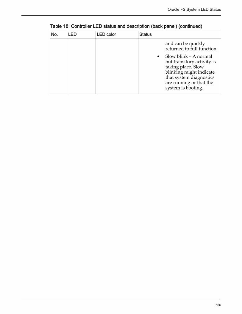
Table 18: Controller LED status and description (back panel) (continued)No. LED LED color Status
and can be quicklyreturned to full function.
• Slow blink – A normalbut transitory activity istaking place. Slowblinking might indicatethat system diagnosticsare running or that thesystem is booting.
Oracle FS System LED Status
556
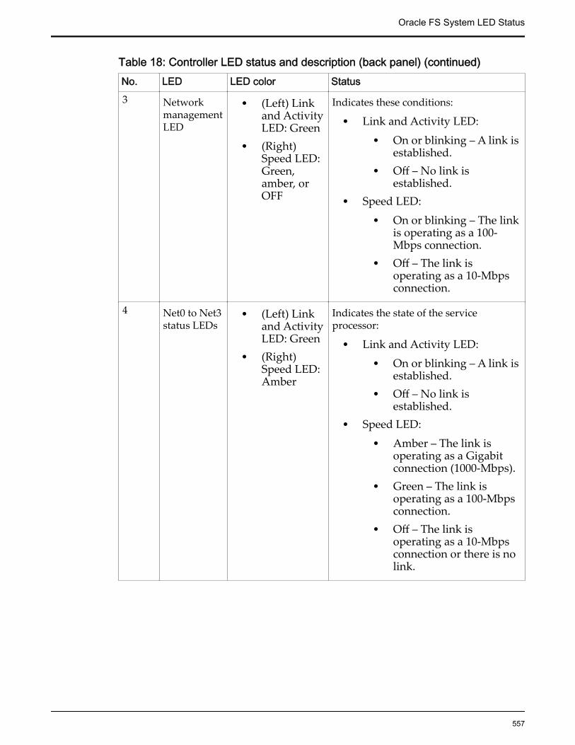
Table 18: Controller LED status and description (back panel) (continued)No. LED LED color Status3 Network
managementLED
• (Left) Linkand ActivityLED: Green
• (Right)Speed LED:Green,amber, orOFF
Indicates these conditions:
• Link and Activity LED:• On or blinking – A link is
established.• Off – No link is
established.• Speed LED:
• On or blinking – The linkis operating as a 100-Mbps connection.
• Off – The link isoperating as a 10-Mbpsconnection.
4 Net0 to Net3status LEDs
• (Left) Linkand ActivityLED: Green
• (Right)Speed LED:Amber
Indicates the state of the serviceprocessor:
• Link and Activity LED:• On or blinking – A link is
established.• Off – No link is
established.• Speed LED:
• Amber – The link isoperating as a Gigabitconnection (1000-Mbps).
• Green – The link isoperating as a 100-Mbpsconnection.
• Off – The link isoperating as a 10-Mbpsconnection or there is nolink.
Oracle FS System LED Status
557

Controller Power Supply LED IndicatorsThe LED indicators on the power supplies are at the left of the fan of each powersupply and provide power activity status.
Table 19: Controller power supply LED status and descriptionIcon Location Name Color Status and meaning
Top OK Green • On – Power supply isfunctional without fault.
• Off – Power supply is off orinitializing.
• Flashing – No function.
Middle AttentionServiceRequired
Amber • On – Normal fault detected.• Off – No faults detected.• Flashing – No function.
Bottom AC or DC Green • On – Input power presentand good.
• Off – Input power notpresent.
• Flashing – No function.
Controller Fan LED IndicatorsA single bi-color LED represents the status of each fan module. The LEDs are onthe motherboard near each fan module, and are visible from the back panel ofthe Controller when you look through the grill below the risers.
Table 20: Controller fan LED status and descriptionColor Status and meaning
Green The fan module is functional without fault.
Amber The fan module has experienced a fault.
Note: There are two LEDs near the status LED for the third fan module. Do notconfuse the FPGA Good and FPGA Diagnostic LEDs with the status LED for thethird fan module.
Oracle FS System LED Status
558

Controller ESM LED IndicatorsThree LEDs represent the status of each energy storage module (ESM). The LEDsare above the release button of each drive.
Figure 503: Controller drive LEDs
Legend 1 Ready to Remove LED
2 Attention Service Required LED
3 OK/Activity LED
4 Power switch
This following table describes the functionality of the ESM LEDs:
Oracle FS System LED Status
559

Table 21: Controller ESM LED status and descriptionIcon Location Name Color Status and meaning
Top Ready to Remove Blue • On – ESM can beremoved as ahot-swapoperation.
• Off – Do notremove the ESM.
• Flashing – ESMis initializing.
Middle Attention ServiceRequired
Amber • On – Normalfault is detected.
• Off – No faultsare detected.
• Flashing – Nofunction.
Bottom OK/Activity Green • On – ESM isfunctionalwithout fault.
• Off – ESM is offor initializing.
• Flashing – ESMread and writeactivity.
Drive Enclosure LED IndicatorsThe LED indicators on the operator panel of the Drive Enclosures provide systemstatus. The LED display identifies the Drive Enclosure by its numeric identifier.
The following figures show the operator panel LEDs for both types of DriveEnclosure.
Oracle FS System LED Status
560

Figure 504: Operator panel LEDs (DE2-24P Drive Enclosure)
Legend 1 System power indicator 3 Locate indicator and logical faultindicator
2 Module fault indicator 4 Chassis ID
Figure 505: Operator panel LEDs (DE2-24C Drive Enclosure)
Legend 1 System power indicator 3 Locate indicator and logical faultindicator
2 Module fault indicator 4 Chassis ID
The following table provides status information on the operator panel LEDs.
Oracle FS System LED Status
561
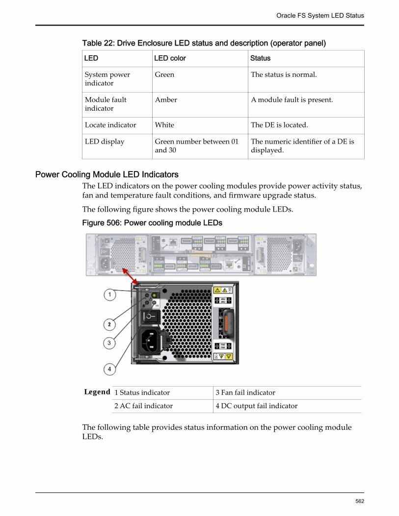
Table 22: Drive Enclosure LED status and description (operator panel)
LED LED color Status
System powerindicator
Green The status is normal.
Module faultindicator
Amber A module fault is present.
Locate indicator White The DE is located.
LED display Green number between 01and 30
The numeric identifier of a DE isdisplayed.
Power Cooling Module LED IndicatorsThe LED indicators on the power cooling modules provide power activity status,fan and temperature fault conditions, and firmware upgrade status.
The following figure shows the power cooling module LEDs.
Figure 506: Power cooling module LEDs
Legend 1 Status indicator 3 Fan fail indicator
2 AC fail indicator 4 DC output fail indicator
The following table provides status information on the power cooling moduleLEDs.
Oracle FS System LED Status
562
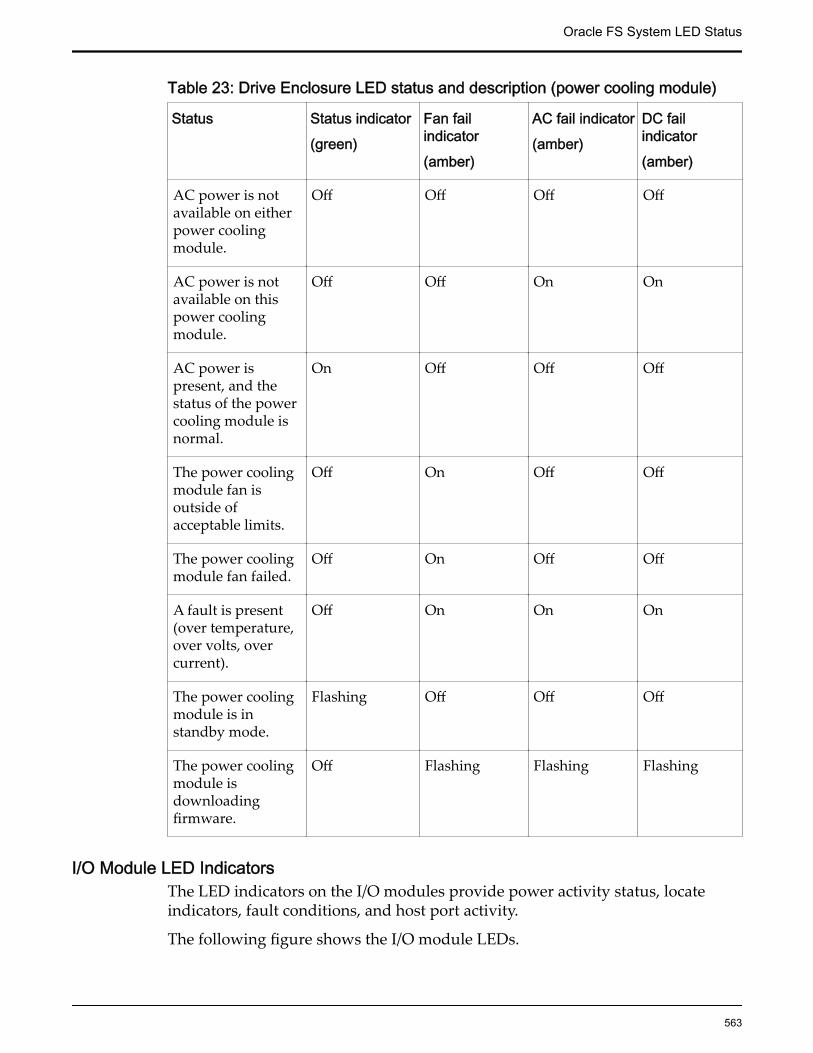
Table 23: Drive Enclosure LED status and description (power cooling module)
Status Status indicator(green)
Fan failindicator(amber)
AC fail indicator(amber)
DC failindicator(amber)
AC power is notavailable on eitherpower coolingmodule.
Off Off Off Off
AC power is notavailable on thispower coolingmodule.
Off Off On On
AC power ispresent, and thestatus of the powercooling module isnormal.
On Off Off Off
The power coolingmodule fan isoutside ofacceptable limits.
Off On Off Off
The power coolingmodule fan failed.
Off On Off Off
A fault is present(over temperature,over volts, overcurrent).
Off On On On
The power coolingmodule is instandby mode.
Flashing Off Off Off
The power coolingmodule isdownloadingfirmware.
Off Flashing Flashing Flashing
I/O Module LED IndicatorsThe LED indicators on the I/O modules provide power activity status, locateindicators, fault conditions, and host port activity.
The following figure shows the I/O module LEDs.
Oracle FS System LED Status
563
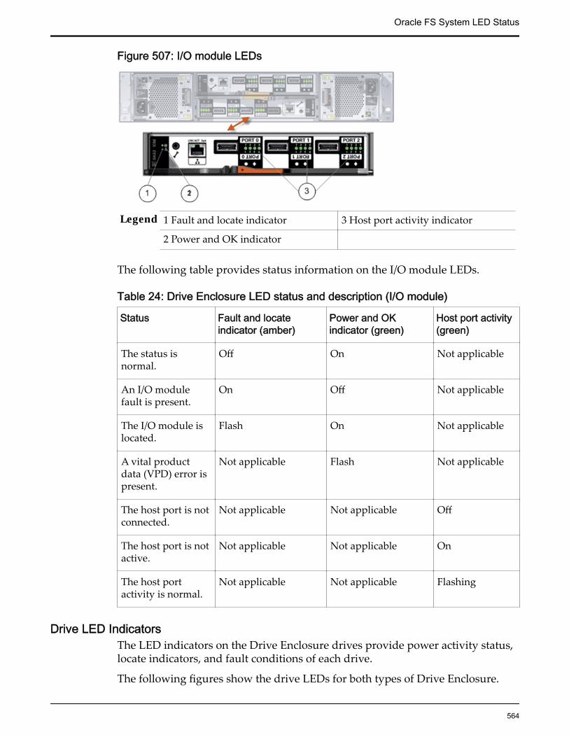
Figure 507: I/O module LEDs
Legend 1 Fault and locate indicator 3 Host port activity indicator
2 Power and OK indicator
The following table provides status information on the I/O module LEDs.
Table 24: Drive Enclosure LED status and description (I/O module)
Status Fault and locateindicator (amber)
Power and OKindicator (green)
Host port activity(green)
The status isnormal.
Off On Not applicable
An I/O modulefault is present.
On Off Not applicable
The I/O module islocated.
Flash On Not applicable
A vital productdata (VPD) error ispresent.
Not applicable Flash Not applicable
The host port is notconnected.
Not applicable Not applicable Off
The host port is notactive.
Not applicable Not applicable On
The host portactivity is normal.
Not applicable Not applicable Flashing
Drive LED IndicatorsThe LED indicators on the Drive Enclosure drives provide power activity status,locate indicators, and fault conditions of each drive.
The following figures show the drive LEDs for both types of Drive Enclosure.
Oracle FS System LED Status
564
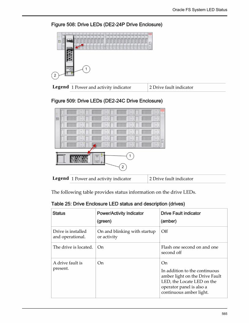
Figure 508: Drive LEDs (DE2-24P Drive Enclosure)
Legend 1 Power and activity indicator 2 Drive fault indicator
Figure 509: Drive LEDs (DE2-24C Drive Enclosure)
Legend 1 Power and activity indicator 2 Drive fault indicator
The following table provides status information on the drive LEDs.
Table 25: Drive Enclosure LED status and description (drives)
Status Power/Activity Indicator(green)
Drive Fault indicator(amber)
Drive is installedand operational.
On and blinking with startupor activity
Off
The drive is located. On Flash one second on and onesecond off
A drive fault ispresent.
On On
In addition to the continuousamber light on the Drive FaultLED, the Locate LED on theoperator panel is also acontinuous amber light.
Oracle FS System LED Status
565

Table 25: Drive Enclosure LED status and description (drives) (continued)
Status Power/Activity Indicator(green)
Drive Fault indicator(amber)
A failure occurredin the power controlcircuit.
Off On
In addition to the continuousamber light on the Drive FaultLED, the Module Fault LED onthe operator panel is also acontinuous amber light.
A failure occurredin the disk array.
On Flash three seconds on and onesecond off.
In addition to the flashingamber light on the Drive FaultLED, the Locate LED on theoperator panel is also acontinuous amber light.
Pilot LED IndicatorsThe Pilot LEDs are on the front panel of the Pilot. Use these diagnostic LEDs todetermine if a component has failed in the Pilot.
The following figure shows the LEDs at the front of the Pilot:
Figure 510: LEDs at the front of the Pilot
Legend 1 Locator LED / Locator button: white 5 Power button
2 Service Action Required LED or Caution orFault LED: Amber
6 Fan fault LED: amber
3 OK LED: green 7 Power supply fault LED:amber
4 Service processor LED: green
The following figure shows the LEDs at the back of the Pilot:
Oracle FS System LED Status
566

Figure 511: LEDs at the back of the Pilot
Legend 1 Poser supply 0 (PS0) 5 Locator LED: white
2 Power supply LEDs: Service Required LED(amber) and AC OK LED (green)
6 Service Required LED:amber
3 Power supply 1 (PS1) 7 Power or OK LED:green
4 Power supply LEDs: Service Required LED(amber) and AC OK LED (green)
There are six, system-level status indicators (LEDs), that are on the Pilot frontpanel and the Pilot back panel. The following table provides status informationon these Pilot LEDs:
Table 26: Pilot LED status and descriptionLED Icon LED color Status
LocatorLED button
White • OFF – Pilot is operating normally• FAST BLINK – To locate a particular
system quickly and easily.• Pressing the Locate button toggles
the LED fast blink on or off.
ServiceActionRequiredLED
Amber • OFF – Normal operation• STEADY ON – Fault present on the
Pilot. This LED lights whenever afault indicator lights for a Pilotreplaceable component.
Note: When this indicator lights up, there is asystem console message that includes arecommended service action.
Oracle FS System LED Status
567

Table 26: Pilot LED status and description (continued)LED Icon LED color Status
Power orOK LED
Green Indicates the operational state of the chassis.This indicator can be in the following states:
• OFF – AC power is not present.
• STEADY BLINK – Standby power is on,but the chassis power is off.
• SLOW BLINK – Startup sequence hasbeen initiated on the host. Thispattern begins soon after you poweron the Pilot. This status indicateseither: (1) POST code checkpoint testsare running on the Pilot host system,or (2) the host is transitioning fromthe powered-on state to the standbystate on shutdown.
• STEADY ON – The Pilot is poweredon, and all host POST codecheckpoint tests are complete. ThePilot is in one of the following states:
• 1) The Pilot host is booting theoperating system (OS).
• 2) The Pilot host is running theOS.
ServiceProcessorLED
Green • OFF – Service processor (SP) is notrunning.
• SLOW BLINK – SP is booting.• STEADY ON – SP is fully
operational.
Top Fan,Processor,MemoryFailure LED
Amber Indicates that one or more of the internal fanmodules, processors, or memory DIMMs havefailed.
• OFF – Indicates steady state; noservice is required.
• STEADY ON – Indicates servicerequired; service the fan modules,processors, or memory DIMMs.
Oracle FS System LED Status
568

Table 26: Pilot LED status and description (continued)LED Icon LED color Status
Rear PowerSupplyFailure LED
Amber Indicates that one of the Pilot power supplieshas failed.
• OFF – Indicates steady state; noservice is required.
• STEADY ON – Indicates servicerequired; service the power supply.
OverTemperature WarningLED
Amber • OFF – Normal operation; no serviceis required.
• STEADY ON – The system isexperiencing an over-temperaturewarning condition.
Note: This is a warning indication, not a fatalover temperature. Might result in the systemoverheating and shutting down unexpectedly.
Pilot Drive LED IndicatorsThere are three LEDs on each Pilot drive. There is only one drive in each Pilot.
Table 27: Pilot drive LED status and descriptionLED Icon LED
colorStatus
OK toRemove
Blue The storage drive can be removed safely during a hot-swap operation.
ServiceRequired
Amber • OFF – Normal operation.• STEADY ON – The system has detected a
fault with the storage drive.
OK/Activity
Green • OFF – Power is off or the system does notrecognize the installed drive.
• STEADY ON – The drive is engaged and isreceiving power.
• STEADY BLINK – There is disk activity.Indicator blinks on and off to indicateactivity
Oracle FS System LED Status
569

Pilot Fan LED IndicatorsEach Pilot fan module has one bicolored LED. These LEDs are on the Pilot sidewall next to the fan modules and are visible when the top cover fan door is open.
Table 28: Pilot fan LED status and descriptionLED Icon LED color Status
FanStatusLED
NONE Bicolored:Amber/Green
• Amber – There is a fan fault.• Green – Fan is properly installed and
operating correctly. No fan errors detected.
Pilot Port LED IndicatorsThe Pilot has LED indicators for Network Management ports and the Ethernetports.
Network Management Port Status LEDsThe Pilot has one 10/100BASE-T Ethernet management domain interface, labeledNET MGT. There are two LEDs on this port. These indicators are visible from theback of the Pilot.
Table 29: Network management port LED status and descriptionLED Location LED
colorStatus
Linkspeed
Top left AmberorGreen
• Amber on - 10BASE-T link• Green on - 100BASE-T link• Off - No link or link down• Flashing - No function
Activity Topright
Green • On - No function• Off - No activity• Flashing - Packet activity
Ethernet Port Status LEDsThe Pilot has four Ethernet ports (NET 3, NET 2, NET 1, NET 0). There are twoLEDs on each port. These LEDs are visible from the back of the Pilot.
Oracle FS System LED Status
570

Table 30: Ethernet port LED status and descriptionLED Location LED color Status
Linkspeed
Top left Green • On - No function.• Off - No activity• Flashing - Packet activity
Activity Topright
Amber orGreen
• Amber on - 100BASE-T link• Green on - 1000/10GBBASE-T link• Off - No link or link down• Flashing - No function
Pilot Motherboard LED IndicatorsThe Pilot motherboard and modules that are installed on the motherboardcontain several LEDs.
Table 31: Motherboard LED status and descriptionLED Description
DDR3DIMM FaultLED
Each of the 16 DDR3 DIMM slots on the motherboard has an amberfault LED associated with it. If a DIMM is faulty, pressing the FaultRemind button on the motherboard signals the service processor tolight the fault LEDs associated with the faulted DIMMs.
ProcessorFault LED
The motherboard includes a fault status indicator (LED) next to each ofthe two processor (CPU) sockets.
These LEDs indicate when a processor is faulty. For example, if onreboot the BIOS detects that there are uncorrectable processor errorsrecorded in the machine check architecture (MCA) registers apparentlyleft over from the previous boot, then the BIOS records and diagnosesthese errors.
If it is determined that a processor is faulty, pressing the Fault Remindbutton on the motherboard signals the service processor to light thefault LED associated with the faulted processor.
Oracle FS System LED Status
571
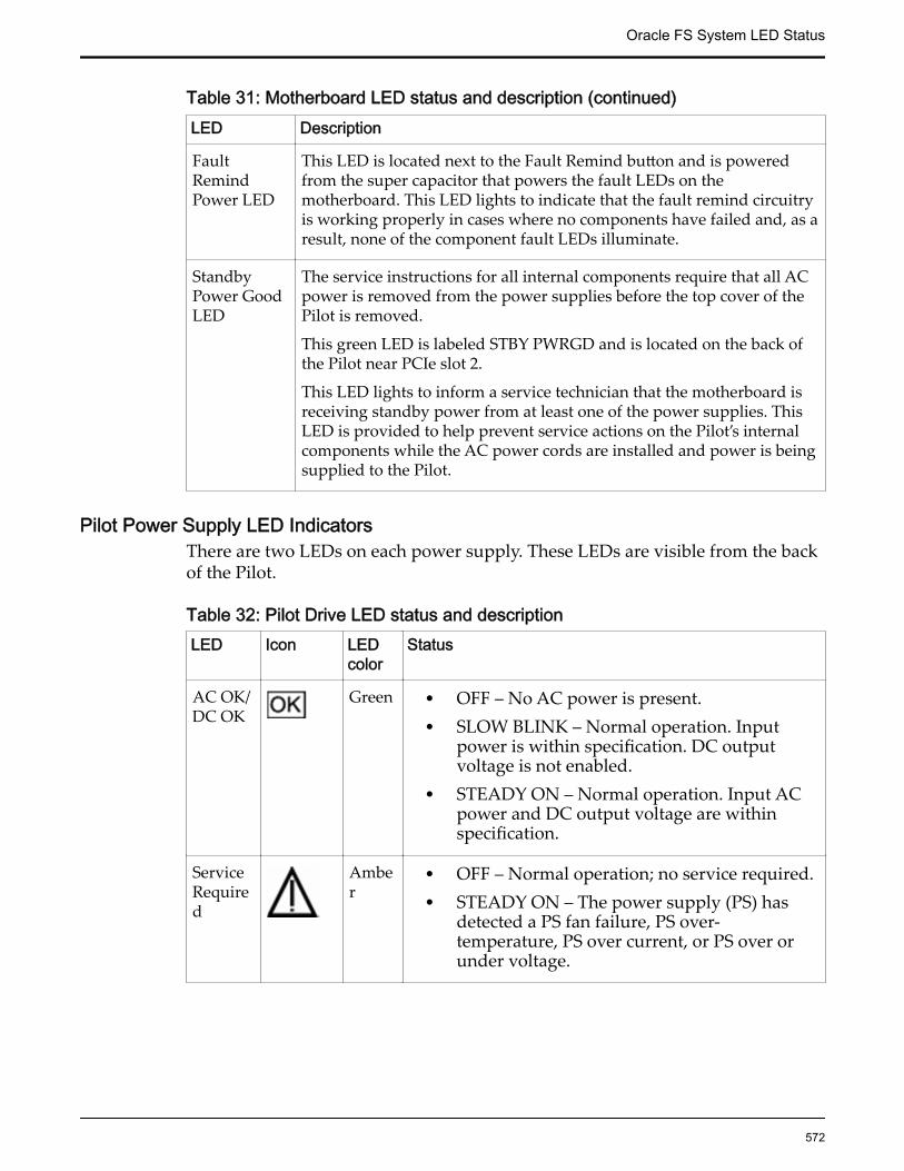
Table 31: Motherboard LED status and description (continued)LED Description
FaultRemindPower LED
This LED is located next to the Fault Remind button and is poweredfrom the super capacitor that powers the fault LEDs on themotherboard. This LED lights to indicate that the fault remind circuitryis working properly in cases where no components have failed and, as aresult, none of the component fault LEDs illuminate.
StandbyPower GoodLED
The service instructions for all internal components require that all ACpower is removed from the power supplies before the top cover of thePilot is removed.
This green LED is labeled STBY PWRGD and is located on the back ofthe Pilot near PCIe slot 2.
This LED lights to inform a service technician that the motherboard isreceiving standby power from at least one of the power supplies. ThisLED is provided to help prevent service actions on the Pilot’s internalcomponents while the AC power cords are installed and power is beingsupplied to the Pilot.
Pilot Power Supply LED IndicatorsThere are two LEDs on each power supply. These LEDs are visible from the backof the Pilot.
Table 32: Pilot Drive LED status and descriptionLED Icon LED
colorStatus
AC OK/DC OK
Green • OFF – No AC power is present.• SLOW BLINK – Normal operation. Input
power is within specification. DC outputvoltage is not enabled.
• STEADY ON – Normal operation. Input ACpower and DC output voltage are withinspecification.
ServiceRequired
Amber
• OFF – Normal operation; no service required.• STEADY ON – The power supply (PS) has
detected a PS fan failure, PS over-temperature, PS over current, or PS over orunder voltage.
Oracle FS System LED Status
572
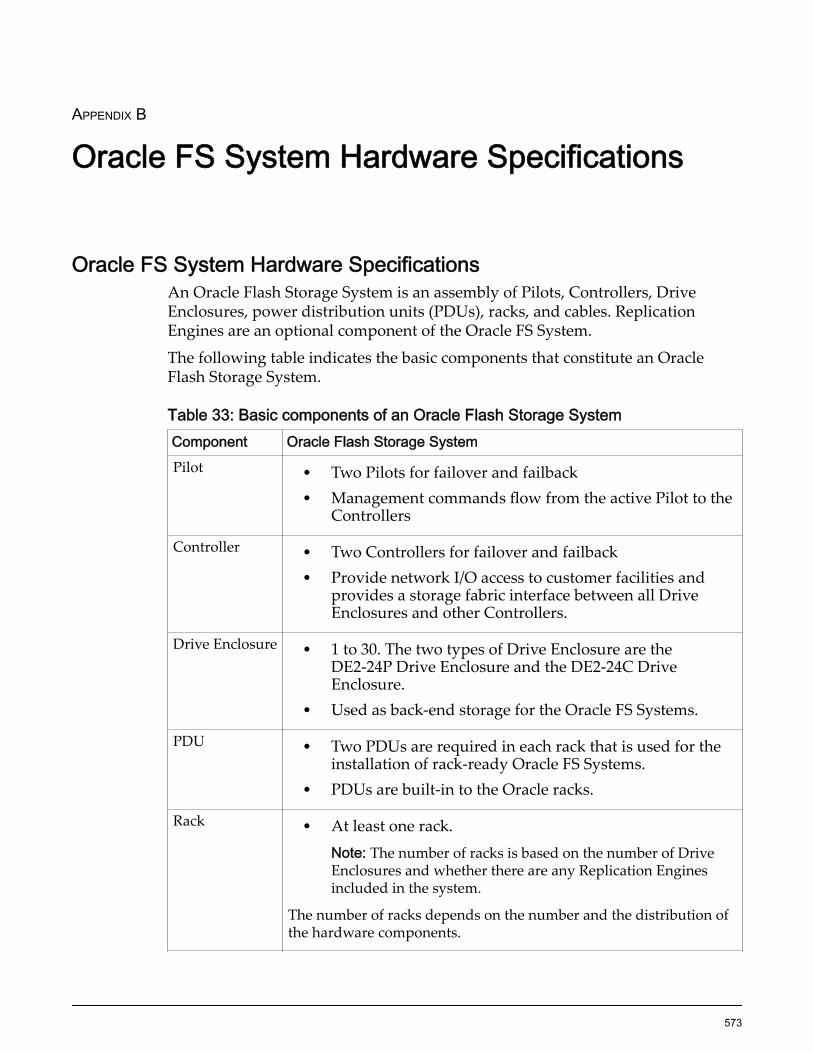
APPENDIX B
Oracle FS System Hardware Specifications
Oracle FS System Hardware SpecificationsAn Oracle Flash Storage System is an assembly of Pilots, Controllers, DriveEnclosures, power distribution units (PDUs), racks, and cables. ReplicationEngines are an optional component of the Oracle FS System.
The following table indicates the basic components that constitute an OracleFlash Storage System.
Table 33: Basic components of an Oracle Flash Storage SystemComponent Oracle Flash Storage SystemPilot • Two Pilots for failover and failback
• Management commands flow from the active Pilot to theControllers
Controller • Two Controllers for failover and failback• Provide network I/O access to customer facilities and
provides a storage fabric interface between all DriveEnclosures and other Controllers.
Drive Enclosure • 1 to 30. The two types of Drive Enclosure are theDE2-24P Drive Enclosure and the DE2-24C DriveEnclosure.
• Used as back-end storage for the Oracle FS Systems.
PDU • Two PDUs are required in each rack that is used for theinstallation of rack-ready Oracle FS Systems.
• PDUs are built-in to the Oracle racks.
Rack • At least one rack.Note: The number of racks is based on the number of DriveEnclosures and whether there are any Replication Enginesincluded in the system.
The number of racks depends on the number and the distribution ofthe hardware components.
573
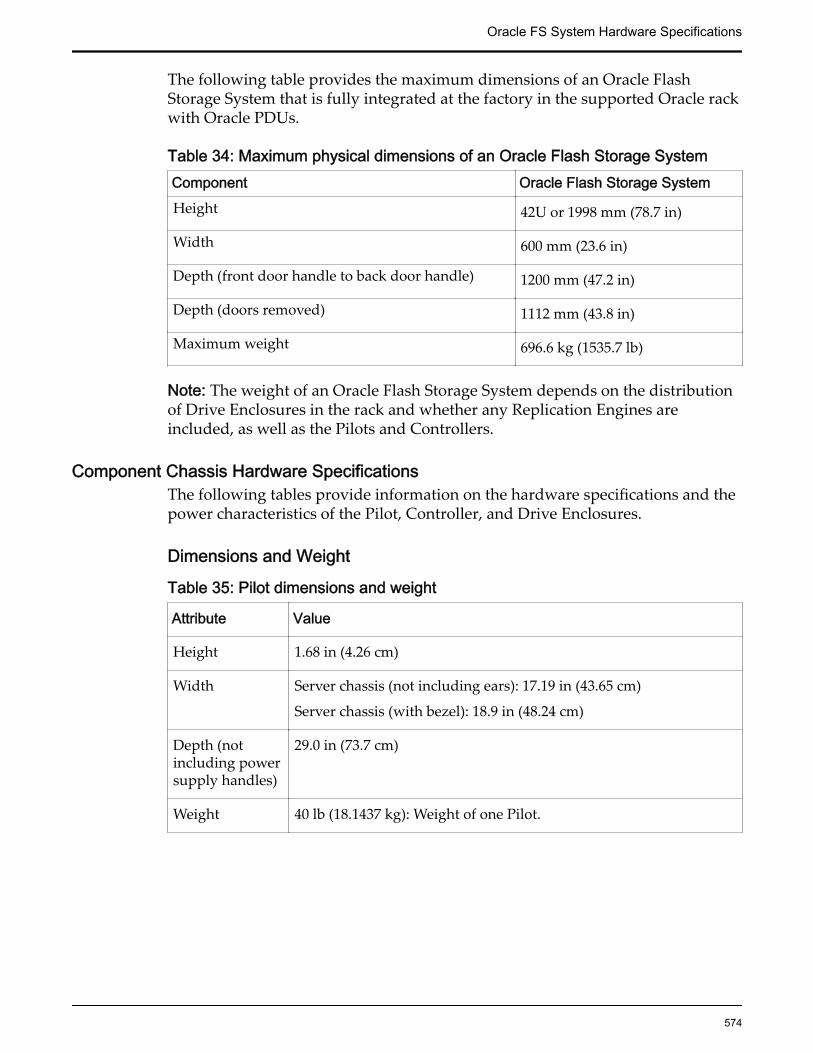
The following table provides the maximum dimensions of an Oracle FlashStorage System that is fully integrated at the factory in the supported Oracle rackwith Oracle PDUs.
Table 34: Maximum physical dimensions of an Oracle Flash Storage SystemComponent Oracle Flash Storage SystemHeight 42U or 1998 mm (78.7 in)
Width 600 mm (23.6 in)
Depth (front door handle to back door handle) 1200 mm (47.2 in)
Depth (doors removed) 1112 mm (43.8 in)
Maximum weight 696.6 kg (1535.7 lb)
Note: The weight of an Oracle Flash Storage System depends on the distributionof Drive Enclosures in the rack and whether any Replication Engines areincluded, as well as the Pilots and Controllers.
Component Chassis Hardware SpecificationsThe following tables provide information on the hardware specifications and thepower characteristics of the Pilot, Controller, and Drive Enclosures.
Dimensions and Weight
Table 35: Pilot dimensions and weight
Attribute Value
Height 1.68 in (4.26 cm)
Width Server chassis (not including ears): 17.19 in (43.65 cm)
Server chassis (with bezel): 18.9 in (48.24 cm)
Depth (notincluding powersupply handles)
29.0 in (73.7 cm)
Weight 40 lb (18.1437 kg): Weight of one Pilot.
Oracle FS System Hardware Specifications
574

Table 36: Controller dimensions and weight
Attribute Value
Height 3.45 in (8.76 cm)
Width 17.52 in (44.55 cm)
Depth 20.25 in (51.435 cm)
Weight 41 lb (18.59 kg)
Table 37: DE2-24P Drive Enclosure dimensions and weight
Attribute Value
Height 3.46 in (8.79 cm); 2U
Weight (withdrives)
55 lb (24.9 kg)
Width Width across mounting flange: 19 in (48.26 cm)
Width across body of enclosure: 17.44 in (44.29 cm)
Depth 24.8 in (62.99 cm)
Table 38: DE2-24C Drive Enclosure dimensions and weight
Attribute Value
Height 6.92 in (17.57 cm); 4U
Weight (withdrives)
110 lb (49.89 kg)
Width Width across mounting flange: 19 in (48.26 cm)
Width across body of enclosure: 17.44 in (44.29 cm)
Depth 24.8 in (62.99 cm)
Oracle FS System Hardware Specifications
575
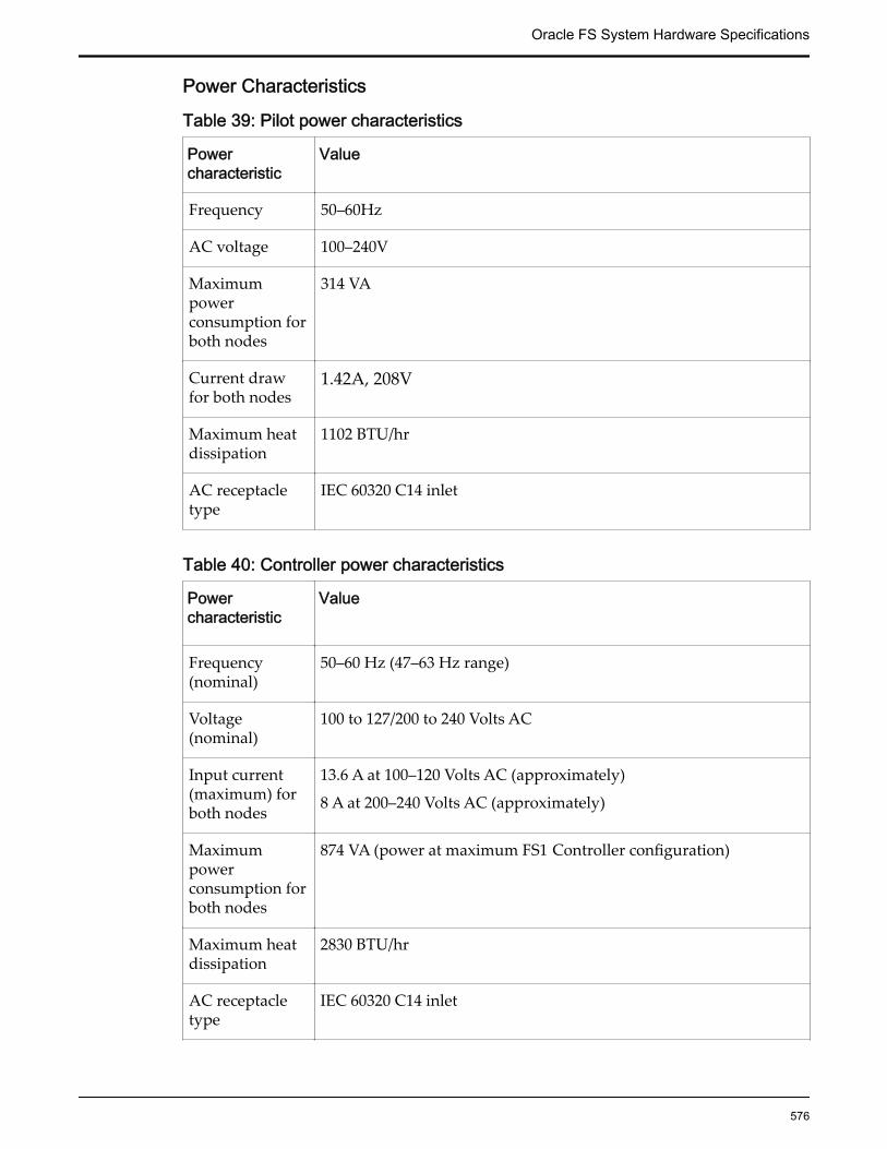
Power Characteristics
Table 39: Pilot power characteristics
Powercharacteristic
Value
Frequency 50–60Hz
AC voltage 100–240V
Maximumpowerconsumption forboth nodes
314 VA
Current drawfor both nodes
1.42A, 208V
Maximum heatdissipation
1102 BTU/hr
AC receptacletype
IEC 60320 C14 inlet
Table 40: Controller power characteristics
Powercharacteristic
Value
Frequency(nominal)
50–60 Hz (47–63 Hz range)
Voltage(nominal)
100 to 127/200 to 240 Volts AC
Input current(maximum) forboth nodes
13.6 A at 100–120 Volts AC (approximately)
8 A at 200–240 Volts AC (approximately)
Maximumpowerconsumption forboth nodes
874 VA (power at maximum FS1 Controller configuration)
Maximum heatdissipation
2830 BTU/hr
AC receptacletype
IEC 60320 C14 inlet
Oracle FS System Hardware Specifications
576

Table 41: Drive Enclosure power characteristics
Powercharacteristic
Value
Maximumoutput power
Maximum power consumption depends on the type of DriveEnclosure (DE2-24P or DE2-24C), its size (2U/4U), andconfiguration.
• 4U HDD= 376VA (4TB HDD)
• 2U SFF = 260VA (900GB SFF HDD)
• 2U SSD = 307VA (19 x 1.6TB SSD)
Frequency 50–60 Hz
Voltage range 100–240 Volts AC rated
Maximum rangeselection
47–63 Hz
Maximuminrush current
20A
Power factorcorrection
95% or less at nominal input voltage
Harmonics Meets EN61000-3-2
Operatingtemperature
5° –40° Celsius (41° —104° Fahrenheit)
PDU Hardware SpecificationsThe PDUs used in a not-racked Oracle FS System installation must provideredundancy for both external AC power source and internal AC powerdistribution to the components. The PDUs must provide sufficient current tomeet the sum of the requirements for the Oracle FS System components.
Oracle PDUs might be purchased for use with non-Oracle racks. The Oracle FSSystem component power cords have been designed to work with vertical styleOracle or third party PDUs. Non-Oracle PDUs must be compatible with Oraclecomponent power cord lengths and plug types. Non-Oracle PDUs must bemounted in a manner such that the power cords provided by Oracle might beused and the PDUs do not obstruct the ability to replace field replaceable units(FRUs) and customer serviceable units (CRUs).
While planning rack-space, ensure that adequate space is also allocated for thePDUs, if using non-Oracle PDUs.
The following tables provide information on the various PDUs for the Oracle FSSystems, with the assumption that there are two PDUs in each rack.
Oracle FS System Hardware Specifications
577

Note: The term “Ph” stands for “phase” in the above tables.
Table 42: Low voltage dual phase PDU for Oracle Flash Storage Systems
Low Voltage 2Ph (2W + ground)
kVA size 10 kVA
Marketing part number 7104982
Manufacturing part number 7051798
Phase 1 Phase
No grounded neutral conductors areprovided in the two input cords.
Voltage input 2x [2Ph (2W+ground)], 208Vac, 50/60 Hz,maximum. 24A per phase
Can be connected to input sources in therange of 200V – 240V AC (nominal)
Number of input cords and plug type 2x NEMA L6-30P
Number of data center receptacles andtype
2x NEMA L6-30R
Maximum input current for each cord 24A
Outlet receptacles (number/type) 42/C13 (seven for each outlet group)
6/C19 (one for each outlet group)
Outlet groups for each PDU 6
PDU power cord length 2 meters (6.6 feet)
PDU power cords are 4 m (13 ft) long, butonly 2 m (6.6 ft) are usable outside of thecabinet.
Table 43: Low voltage three-phase PDU for Oracle Flash Storage Systems
Low Voltage 3Ph (3W + ground)
kVA size 15 kVA
Marketing part number 7104979
Manufacturing part number 7051909
Oracle FS System Hardware Specifications
578

Table 43: Low voltage three-phase PDU for Oracle Flash Storage Systems(continued)
Low Voltage 3Ph (3W + ground)
Phase 3
No grounded neutral conductors areprovided in the input cords.
Voltage input 3Ph [(3W+ground)] 208Vac, 50/60 Hz,maximum. 40A per phase
Can be connected to Ph-Ph input sources inthe range of 190V – 220V AC (nominal)
Number of input cords and plug type 1x IEC 309, 60A (Hubbell C460P9W orequivalent)
Number of data center receptacles andtype
1x IEC 309, 60A (Hubbell 460R9S orequivalent)
Maximum input current for each cord 40A
Outlet receptacles (number/type) 42/C13 (seven for each outlet group)
6/C19 (one for each outlet group)
Outlet groups for each PDU 6
PDU power cord length 2 meters (6.6 feet)
PDU power cords are 4 meters (13 feet)long, but sections are connected for internalrouting in the rack.
Table 44: High voltage single phase PDU for Oracle Flash Storage Systems
High Voltage 1Ph (2W + ground)
kVA size 10 kVA
Marketing part number 7104983
Manufacturing part number 7051801
Phase 1
Voltage input 2x [2Ph. (2W+ground)] 230Vac, 50 Hz,maximum. 25A per phase
Can be connected to Ph-N input sources inthe range of 220V – 240V AC (nominal)
Oracle FS System Hardware Specifications
579
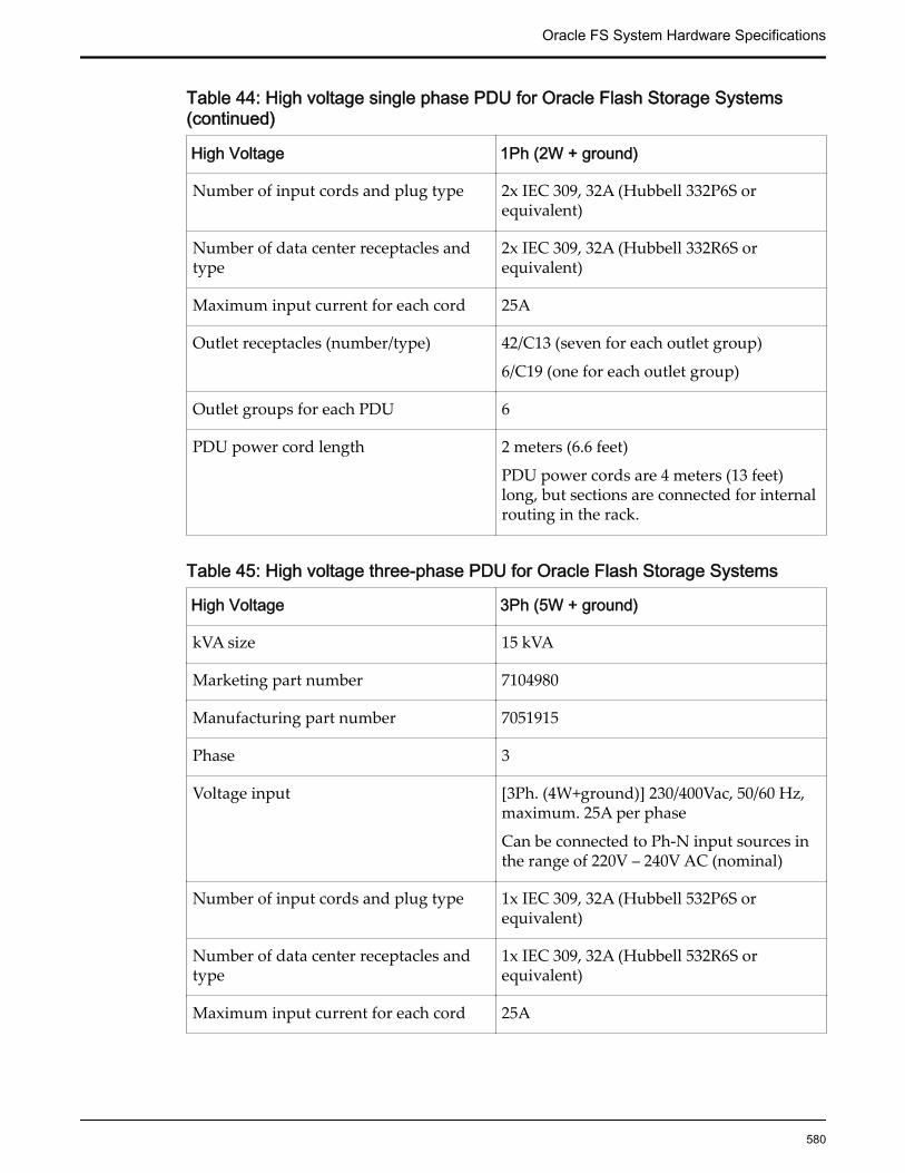
Table 44: High voltage single phase PDU for Oracle Flash Storage Systems(continued)
High Voltage 1Ph (2W + ground)
Number of input cords and plug type 2x IEC 309, 32A (Hubbell 332P6S orequivalent)
Number of data center receptacles andtype
2x IEC 309, 32A (Hubbell 332R6S orequivalent)
Maximum input current for each cord 25A
Outlet receptacles (number/type) 42/C13 (seven for each outlet group)
6/C19 (one for each outlet group)
Outlet groups for each PDU 6
PDU power cord length 2 meters (6.6 feet)
PDU power cords are 4 meters (13 feet)long, but sections are connected for internalrouting in the rack.
Table 45: High voltage three-phase PDU for Oracle Flash Storage Systems
High Voltage 3Ph (5W + ground)
kVA size 15 kVA
Marketing part number 7104980
Manufacturing part number 7051915
Phase 3
Voltage input [3Ph. (4W+ground)] 230/400Vac, 50/60 Hz,maximum. 25A per phase
Can be connected to Ph-N input sources inthe range of 220V – 240V AC (nominal)
Number of input cords and plug type 1x IEC 309, 32A (Hubbell 532P6S orequivalent)
Number of data center receptacles andtype
1x IEC 309, 32A (Hubbell 532R6S orequivalent)
Maximum input current for each cord 25A
Oracle FS System Hardware Specifications
580

Table 45: High voltage three-phase PDU for Oracle Flash Storage Systems(continued)
High Voltage 3Ph (5W + ground)
Outlet receptacles (number/type) 42/C13 (seven for each outlet group)
6/C19 (one for each outlet group)
Outlet groups for each PDU 6
PDU power cord length 2 meters (6.6 feet)
PDU power cords are 4 meters (13 feet)long, but sections are connected for internalrouting in the rack.
System Power RequirementsThe total power consumed by the Oracle FS1 Flash Storage System is dependenton the configuration of the system. To determine the system electrical inputratings for Oracle Flash Storage Systems that use the Oracle supported PDUs,refer to the PDU information provided for Oracle Flash Storage Systems.
Oracle Flash Storage Systems require redundant input power feeds for properfault tolerant operation.
Note: Ensure that you have the exact power load and current requirements foryour specific Oracle FS System at hand.
If non-Oracle PDUs are used, you must determine the electrical input ratings ofthe Oracle FS System configuration.
System Packaging and TransportationAll packaging and transportation are tested in accordance with Oracle ShippingPackage Test, Doc. No. 950-1291-01.
System EnvironmentalsTable 46: System altitude specifications
Mode Elevation
Operational –196 to 10498.7 feet (–60 to 3,200 meters)
Non-operational
–196 to 40026.2 feet (–60 to 12,200 meters)
Oracle FS System Hardware Specifications
581
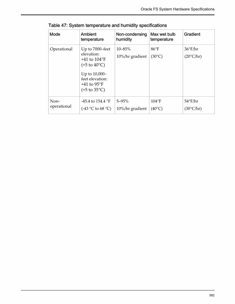
Table 47: System temperature and humidity specifications
Mode Ambienttemperature
Non-condensinghumidity
Max wet bulbtemperature
Gradient
Operational Up to 7000–feetelevation:+41 to 104°F(+5 to 40°C)
Up to 10,000–feet elevation:+41 to 95°F(+5 to 35°C)
10–85%
10%/hr gradient
86°F
(30°C)
36°F/hr
(20°C/hr)
Non-operational
-45.4 to 154.4 °F
(-43 °C to 68 °C)
5–95%
10%/hr gradient
104°F
(40°C)
54°F/hr
(30°C/hr)
Oracle FS System Hardware Specifications
582
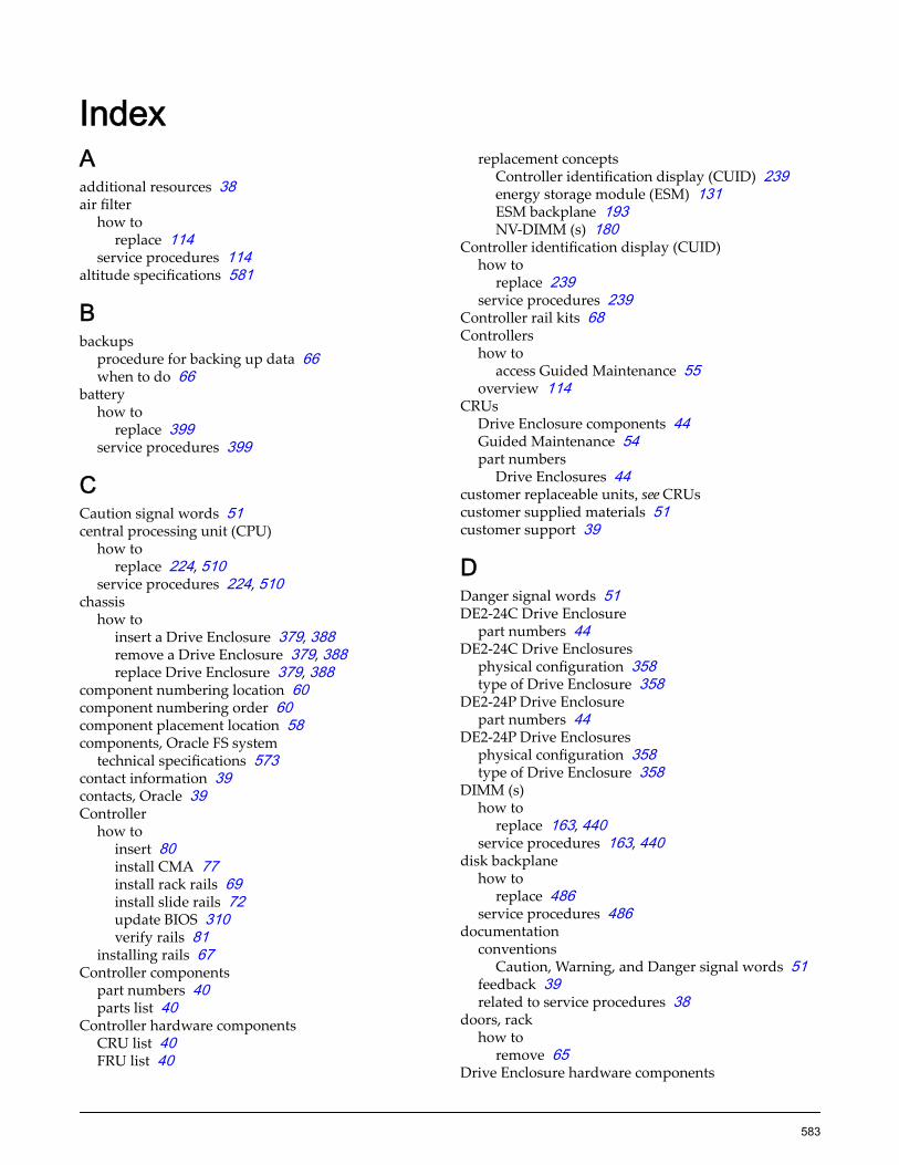
IndexAadditional resources 38air filter
how toreplace 114
service procedures 114altitude specifications 581
Bbackups
procedure for backing up data 66when to do 66
batteryhow to
replace 399service procedures 399
CCaution signal words 51central processing unit (CPU)
how toreplace 224, 510
service procedures 224, 510chassis
how toinsert a Drive Enclosure 379, 388remove a Drive Enclosure 379, 388replace Drive Enclosure 379, 388
component numbering location 60component numbering order 60component placement location 58components, Oracle FS system
technical specifications 573contact information 39contacts, Oracle 39Controller
how toinsert 80install CMA 77install rack rails 69install slide rails 72update BIOS 310verify rails 81
installing rails 67Controller components
part numbers 40parts list 40
Controller hardware componentsCRU list 40FRU list 40
replacement conceptsController identification display (CUID) 239energy storage module (ESM) 131ESM backplane 193NV-DIMM (s) 180
Controller identification display (CUID)how to
replace 239service procedures 239
Controller rail kits 68Controllers
how toaccess Guided Maintenance 55
overview 114CRUs
Drive Enclosure components 44Guided Maintenance 54part numbers
Drive Enclosures 44customer replaceable units, see CRUscustomer supplied materials 51customer support 39
DDanger signal words 51DE2-24C Drive Enclosure
part numbers 44DE2-24C Drive Enclosures
physical configuration 358type of Drive Enclosure 358
DE2-24P Drive Enclosurepart numbers 44
DE2-24P Drive Enclosuresphysical configuration 358type of Drive Enclosure 358
DIMM (s)how to
replace 163, 440service procedures 163, 440
disk backplanehow to
replace 486service procedures 486
documentationconventions
Caution, Warning, and Danger signal words 51feedback 39related to service procedures 38
doors, rackhow to
remove 65Drive Enclosure hardware components
583

backups for 66how to
insert a drive 362insert a power cooling module 372insert an I/O module 367remove a drive 362remove a Drive Enclosure 388remove a power cooling module 372remove an I/O module 367replace a drive 362replace a Drive Enclosure 388replace a power cooling module 372replace an I/O module 367
replacement conceptsdrives 360
Drive Enclosure rail kits 86Drive Enclosures
components list 44CRU list 44FRU list 44how to
access Guided Maintenance 55install rails 88replace a chassis 378, 379, 388replace drives 360, 362replace I/O modules 367replace power cooling modules 372
installing rails 83logical names 60part numbers 44physical configuration 358physical names 60types of
DE2-24C Drive Enclosure 358DE2-24P Drive Enclosure 358
drivesDrive Enclosures
HDDs 358large form factor (LFF) 358small form factor drives (SFF) 358SSDs 358
how toinsert 362remove 362replace 362
part numbers 44service procedures 362
Eeducation programs 39electrostatic discharge (ESD)
precautions 51energy storage module (ESM)
how toreplace 131
service procedures 131
environment, data centerOracle FS system requirements 581
ESM backplanehow to
replace 193service procedures 193
Ffan modules
how toreplace 117, 433
service procedures 117, 433feedback, documentation 39field replaceable units, see FRUsFRUs
Drive Enclosure components 44Guided Maintenance 54part numbers
Drive Enclosures 44
Gground straps
personal ESD 51Guided Maintenance
CRUs 54FRUs 54how to
access Guided Maintenance 55replace a CRU 55replace a FRU 55
overview 52
Hhardware components
CRUsDrive Enclosures 44
Drive Enclosure parts list 44FRUs
Drive Enclosures 44how to
insert a Drive Enclosure 379, 388remove a Drive Enclosure 379replace a drive 362replace a Drive Enclosure 378, 379, 388replace a power cooling module 372replace an I/O module 367
replacement conceptsair filter 114central processing unit (CPU) 224DIMM (s) 163fan modules 117HBA 149heat sink 211LED alarm assembly 249
Index
584

motherboard 270motherboard cables 313power distribution board (PDB) 327power supplies 126riser board assembly 139
types of Drive EnclosuresDE2-24C 358DE2-24P 358
hardware problemshow to
perform emergency back up 66replace battery 399replace central processing unit (CPU) 224, 510replace disk backplane 486replace drives 360replace heat sink 211, 500replace motherboard 270, 522replace power distribution board (PDB) 327
hardware specificationsaltitude 581humidity 581PDU 577temperature 581
hazard signal wordsin English 51
HBAhow to
replace 149service procedures 149
HDDssee also hard disk drives (HDDs)
how toreplace a drive 362replace drives 360
see also hard disk drives (HDDs)heat sink
how toreplace 211, 500
service procedures 211, 500how to
insert 114, 117, 126, 131, 139, 149, 163, 180, 193,239, 249, 313, 409, 418, 429, 433, 440, 449, 481remove 114, 117, 126, 131, 139, 149, 163, 180, 193,239, 249, 313, 409, 418, 429, 433, 440, 449, 481
humidity specifications 581
II/O modules
how toinsert 367remove 367replace 367
part numbers 44service procedures 367
inserta Drive Enclosure 379, 388
air filter 114Controller identification display (CUID) 239DIMM (s) 163, 440drives 362energy storage module (ESM) 131ESM backplane 193fan module 117, 433HBA 149I/O modules 367LED alarm assembly 249motherboard cables 313NV-DIMM (s) 180Pilot chassis 449power cooling modules 372power supplies 126, 429riser board assembly 139, 418SAS HBA 409SAS HDD 481
installation procedurestools, required 51
Llarge form factor (LFF) drives, see drivesLED alarm assembly
how toreplace 249
service procedures 249LED status 551
Mmotherboard
how toreplace 270, 522
service procedures 270, 522motherboard cable kit(s/es)
how toreplace 313
motherboard cableshow to
replace 313location 294service procedures 313type 294
Nnotice conventions, safety 51NV-DIMM (s)
how toreplace 180
service procedures 180
Oonline help 39Oracle documentation 39
Index
585

Oracle FS systemcomponent numbering
location 60order 60
component placementlocation 58
hardware specifications 573Oracle FS System
Drive Enclosuresreplace a drive 362replace a Drive Enclosure 378replace a power cooling module 372replace an I/O module 367
how toback up data 67prepare the rack 64
LED status indicators 551power cycling 67
Oracle FS System ManagerGuided Maintenance 52
Oracle FS SystemsControllers
overview 114Pilots, overview 399
Oracle rackshow to
remove rack doors 65Oracle Technology Network (OTN) 39
Ppanels, rack
how toremove 65
part numbersController components 40DE2-24C Drive Enclosure chassis 44DE2-24P Drive Enclosure chassis 44drives 44I/O modules 44Pilot components 48power cooling modules 44
parts listController components 40Pilot components 48
PDUshardware specifications 577
Pilothow to
create Pilot OS image 484insert 110install CMA 108install rack rails 105install slide rails 107update BIOS 547verify rails 112
Pilot chassis
how toreplace 449
service procedures 449Pilot components
part numbers 48parts list 48
Pilot hardware componentsCRU list 48FRU list 48replacement concepts
battery 399central processing unit (CPU) 510DIMM (s) 440disk backplane 486fan modules 433heat sink 500motherboard 522Pilot chassis 449power supplies 429riser board assembly 418SAS HBA 409SAS HDD 481
Pilot image 484Pilot rail kits 104Pilots
how toaccess Guided Maintenance 55
installing rails 104overview 399
powerfeed requirements of the system 581
power cooling moduleshow to
insert 372remove 372replace 372
part numbers 44service procedures 372
power cycling, system 67power distribution board (PDB)
how toreplace 327
power supplieshow to
replace 126, 429service procedures 126, 429
prepare racks 64product support 39
Rrack
how toinstall Drive Enclosures 88verify rail installation 81, 112
safety precautions 66rack-ready 68, 104
Index
586

rackshow to
remove doors 65remove panels 65
rail kits 68, 86, 104rails
how toinstall Drive Enclosures rails 88verify 81, 112
related books 38remove
a Drive Enclosure 379, 388air filter 114Controller identification display (CUID) 239DIMM (s) 163, 440drives 362energy storage module (ESM) 131ESM backplane 193fan module 117, 433HBA 149I/O modules 367LED alarm assembly 249motherboard cables 313NV-DIMM (s) 180Pilot chassis 449power cooling modules 372power supplies 126, 429rack
doors 65panels 65
riser board assembly 139, 418SAS HBA 409SAS HDD 481
replacea Drive Enclosure 378, 379, 388air filter 114battery 399central processing unit (CPU) 224, 510Controller identification display (CUID) 239DIMM (s) 163, 440disk backplane 486drives 362energy storage module (ESM) 131ESM backplane 193fan module 117, 433HBA 149heat sink 211, 500I/O modules 367LED alarm assembly 249motherboard 270, 522motherboard cable kit 313motherboard cables 313NV-DIMM (s) 180Pilot chassis 449power cooling modules 372power distribution board (PDB) 327power supplies 126, 429
riser board assembly 139, 418SAS HBA 409SAS HDD 481
replaceable componentsGuided Maintenance 54how to
access Guided Maintenance 55replacement concepts
Drive Enclosuredrives 360
Pilotbattery 399central processing unit (CPU) 510disk backplane 486heat sink 500motherboard 522
riser board assemblyhow to
replace 139, 418service procedures 139, 418
Ssafety
notice conventions 51safety precautions 66sales information 39SAS HBA
how toreplace 409
service procedures 409SAS HDD
how toreplace 481
service procedures 481service procedures
air filter 114back up data 66battery 399central processing unit (CPU) 224, 510Controller identification display (CUID) 239CRUs 54DIMM (s) 163, 440disk backplane 486energy storage module (ESM) 131ESM backplane 193fan modules 117, 433FRUs 54Guided Maintenance 52, 54HBA 149heat sink 211, 500how to
access Guided Maintenance 55remove rack doors 65remove rack panels 65replace drives 360
LED alarm assembly 249
Index
587

motherboard 270, 522motherboard cables 313NV-DIMM (s) 180Pilot chassis 449power supplies 126, 429replace a Drive Enclosure 379, 388replace drives 362replace I/O modules 367replace power cooling modules 372riser board assembly 139, 418SAS HBA 409SAS HDD 481
signal words 51small form factor (SFF) drives, see drivesSSDssee also solid state drives (SSDs)
how toreplace a drive 362replace drives 360
see also solid state drives (SSDs)storage enclosures, see Drive EnclosuresSupport portal 39
Ttemperature specifications 581tools, required 51training programs 39
Uupdate
Controller BIOS 310Pilot BIOS 547
WWarning signal words 51
Index
588