fsme_d to fsmf replacement procedure_ts sran sw 188 i7
DESCRIPTION
FSME_D to FSMF Replacement Procedure_TS SRAN SW 188 I7TRANSCRIPT
TS-3GBTS-SW-188 - Page 1/52 © Nokia Solutions and Networks 2014 Version 7.0 Confidential
Technical Support Note
TS-3GBTS-SW-188
FSME/D to FSMF replacement procedure
Radio Networks F lexi Mul t i radio BTS WCDMA Approval date: (17-Sep-2014)
This document contains following type of information
Informative X
Preventive
Corrective
Additional categorization
Urgent
Security
Release Upgrade
SW Update
Parameterization
Information is classified as
Internal
Public X
Customer Specific
Nokia Solutions and Networks is continually striving to reduce the adverse environmental effects of its products and services. We would like to encourage you as our customers and users to join us in working towards a cleaner, safer environment. Please recycle product packaging and follow the recommendations for power use and proper disposal of our products and their components.
If you should have questions regarding our Environmental Policy or any of the environmental services we offer, please contact us at Nokia Solutions and Networks for additional information.
TS-3GBTS-SW-188 - Page 2/52 © Nokia Solutions and Networks 2014 Version 7.0 Confidential
Table of Contents 1. Validity......................................................................................................................................... 5 2. Terminology................................................................................................................................. 5 3. Compatibility ................................................................................................................................ 5 4. Keywords .................................................................................................................................... 5 5. Introduction ................................................................................................................................. 5 6. SW management ......................................................................................................................... 6
6.1 ..... FSMF factory load SW........................................................................................................... 6 6.2 ..... SW update – New, out of box FSMF ...................................................................................... 7 6.3 ..... SW update – Used FSMF ...................................................................................................... 7 6.4 ..... SW updates from WN8.0 2.1 to WN8.0 3.1 and later ............................................................. 8
7. Instructions .................................................................................................................................. 9 7.1 ..... Time required ........................................................................................................................ 9 7.2 ..... Preparations .......................................................................................................................... 9 7.3 ..... Steps prior to site visit ......................................................................................................... 10 7.4 ..... Steps during to site visit ....................................................................................................... 25 7.5 ..... Additional information .......................................................................................................... 46
7.5.1 FSMF sub-modules ....................................................................... 46 7.5.2 FSMF synchronization cables ....................................................... 46 7.5.3 FSMF GPS feeding cables ............................................................ 46 7.5.4 FSMF EAC cables ......................................................................... 47 7.5.5 FSMF EAC signal and pin assignment .......................................... 47 7.5.6 Radio modules with 6 GB RP3-01 link speed support ................... 48 7.5.7 SFP modules for 6 GB RP3-01 link speed ..................................... 48 7.5.8 SFP modules for 3 GB RP3-01 link speed ..................................... 48 7.5.9 FSMF interfaces ............................................................................ 49 7.5.10 FSMF LMP connector pin map ...................................................... 51
Contact:
Contact your local Nokia Solutions and Networks support
Summary of changes:
03-Oct-2013 1.0 Approved instruction set.
04-Nov-2013 2.0 Approved instruction set.
12-Dec-2013 3.0 Approved instruction set.
11-Feb-2014 4.0 Approved instruction set.
24-Mar-2014 5.0 Approved instruction set.
23-July-2014 6.0 Approved instruction set.
17-Sep-2014 7.0 Approved instruction set.

TS-3GBTS-SW-188 - Page 3/52 © Nokia Solutions and Networks 2014 Version 7.0 Confidential
Changes between issues 1.0 and 2.0 Chapter 6 • Factory new FSMF information and recommended SW upgrade paths updated Chapter 7 • Step 1.1, 7.1. FSME/D power distribution unit reuse with FSMF noted • Step 5.5. CCCH processing set commissioning step clarified • Step 7.4. FPMA/battery backup commissioning step clarified • Step 10.1 in 2G-3G RF sharing, 2G BTS to be updated after 3G BTS commissioning Chapter 7.4.9 • FSMF front panel interface information added Chapter 7.4.10 • FSMF LMP connector pin out map added Changes between issues 2.0 and 3.0 Chapter 3 • SW compatibility information updated. Chapter 6 • Supported SW upgrade paths updated. Chapter 7 • Step 5.5. CCCH processing set License Key usage clarified. • Step 9.2, 9.3. FSME/D backup SCF conversion for FSMF use added. • Step 9.1. Planned commissioning instruction removed - Template commissioning is
preferred. Chapter 7.2 • Preparations updated Changes between issues 3.0 and 4.0 Chapter 6.2, 6.3 • Supported RU30 SW upgrade paths updated for A.103 FSMF. Chapter 7.3 • Step 1.2 added details to regenerate WBTS licenses Chapter 7.4 • Step 5.6, 5.7, 5.8 and 9.5, 9.6, 9.7 added details when baseband capacity is changed from
2 x FSME to 1 x FSMF and when more than 6 cells with HSPA are present. • Step 9.1 added details when backup SCF from RU30/RU40 in template commissioning Changes between issues 4.0 and 5.0 Chapter 6.2 • Repaired A.102 FSMF BTS SW version updated. Chapter 7.2 • Material list updated to support external IP devices with FSMF Chapter 7.3 • Step 6.3. Site specific IP configuration is different between FSME/D and FSMF. Chapter 7.4 • Step 7.9. Support for external IP devices with FSMF • Step 9.2. Site specific IP configuration is different between FSME/D and FSMF. • Step 9.9. Antenna Line Settings – note added for RealTilt commissioning
TS-3GBTS-SW-188 - Page 4/52 © Nokia Solutions and Networks 2014 Version 7.0 Confidential
Changes between issues 5.0 and 6.0 Chapter 7.3 • Step 1.2 Clarified that FSMF support feature RAN1849 BTS Licensing Logical Target ID Changes between issues 6.0 and 7.0 Chapter 6.1 • Added note to check PC firewall settings to allow successful software download and
commissioning file transfer to BTS. Chapter 6.4 • Added information of possible additional BTS reset required during SW upgrade from
WN8.0 2.0 to WN8.0 3.1 and later. Chapter 7.3 • Step 4.1 Added note to check PC firewall settings. Chapter 7.4 • Step 9.9 Added note to check PC firewall settings.

TS-3GBTS-SW-188 - Page 5/52 © Nokia Solutions and Networks 2014 Version 7.0 Confidential
Purpose
The purpose of this TSN is to give instructions on how to replace the existing FSME/D Flexi Multiradio System module in WCDMA BTS Site with FSMF Flexi Multiradio System module.
1. VALIDITY
Product Product code Core Module
Flexi Multiradio System Module, FSMD 471402A 083780A
Flexi Multiradio System Module, FSME 471469A 083833A
Flexi Multiradio System Module, FSMF 472181A 084792A
System level BTS Software
Flexi Multiradio WCDMA BTS RU40 WN8.0 2.0
2. TERMINOLOGY
The following terminology is used in this document: FSMD Flexi Multiradio System Module (rel 2) FSME Flexi Multiradio System Module (rel 2) FSMF Flexi Multiradio System Module (rel 3) RFM Flexi Multiradio RF module / Remote Radio head FTIF Transport sub-module FBBA Extension baseband sub-module FPFD Power distribution sub-module
3. COMPATIBILITY
WCDMA BTS SW support for Flexi Multiradio System Module FSMF A.102 is available starting from WN7.0 3.0.1/WN8.0 2.0 and for Multiradio System Module FSMF A.103 starting from WN7.0 3.0/WN8.0 2.0.
4. KEYWORDS
WN7.0 3.0, WN7.0 3.0.1, WN8.0 2.0, System module swap, System module replacement, WCDMA, FSMD, FSME, FSMF, A.102, A.103
5. INTRODUCTION
This TSN gives the user guidelines and instructions on how to replace an existing FSMD/E System module with FSMF System module while maintaining the existing site functionality, features and capacity. The instructions will cover both dedicated 3G BTS as well as 3G-2G RF Sharing site scenarios. References to the existing Flexi Multiradio 10 BTS documentation are made (available in NOLS). WCDMA RAN, Rel. RU40, Operating Documentation, Issue 03. Check WCDMA RAN, Rel. RU40, Operating Documentation Change Delivery sets for latest updates.
TS-3GBTS-SW-188 - Page 6/52 © Nokia Solutions and Networks 2014 Version 7.0 Confidential
6. SW MANAGEMENT
Out of box FSMF System module is delivered with so called ‘factory load SW’.
6.1 FSMF factory load SW
All new FSMF version A.103 modules are delivered with preinstalled LN4.0 1.2 (LN4.0 ENB 1202_781_57) SW that has hardware security enabled (SW Verification Agent). Repaired FSMF version A.102 modules are also updated to same LN4.0 1.2 (LN4.0_ENB_1202_ 781_57) SW since week 11/2014. After this, FSMF version A.102 works exactly the same as FSMF A.103, including RAN2423 SW Verification agent (WCDMA) and LTE940 SW Verification agent (LTE/TD-LTE) features. Some FSMF A.102 modules delivered from NSN hubs may still contain older factory SW (LN4.0_ENB_1202_696_00). In this case it is recommended to check the possible SW upgrade options in reference documentation (chapter 8).
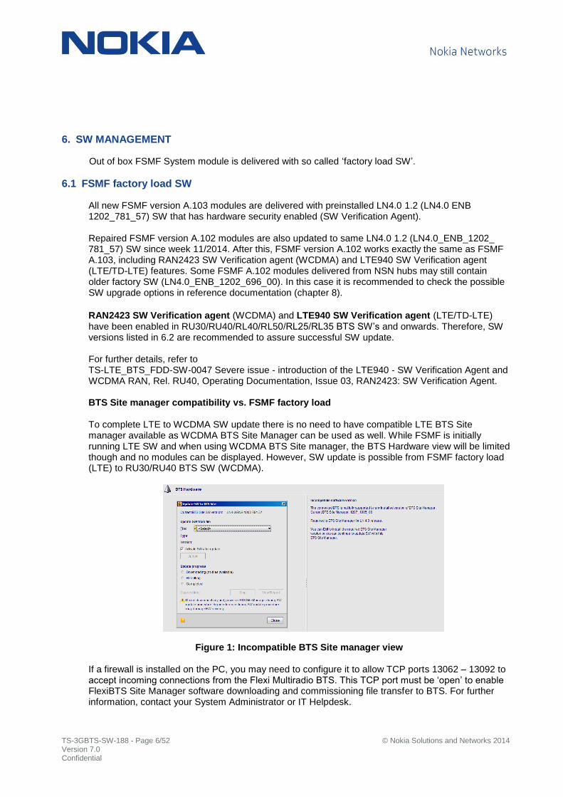
RAN2423 SW Verification agent (WCDMA) and LTE940 SW Verification agent (LTE/TD-LTE) have been enabled in RU30/RU40/RL40/RL50/RL25/RL35 BTS SW’s and onwards. Therefore, SW versions listed in 6.2 are recommended to assure successful SW update. For further details, refer to TS-LTE_BTS_FDD-SW-0047 Severe issue - introduction of the LTE940 - SW Verification Agent and WCDMA RAN, Rel. RU40, Operating Documentation, Issue 03, RAN2423: SW Verification Agent. BTS Site manager compatibility vs. FSMF factory load To complete LTE to WCDMA SW update there is no need to have compatible LTE BTS Site manager available as WCDMA BTS Site Manager can be used as well. While FSMF is initially running LTE SW and when using WCDMA BTS Site manager, the BTS Hardware view will be limited though and no modules can be displayed. However, SW update is possible from FSMF factory load (LTE) to RU30/RU40 BTS SW (WCDMA).
Figure 1: Incompatible BTS Site manager view
If a firewall is installed on the PC, you may need to configure it to allow TCP ports 13062 – 13092 to accept incoming connections from the Flexi Multiradio BTS. This TCP port must be ‘open’ to enable FlexiBTS Site Manager software downloading and commissioning file transfer to BTS. For further information, contact your System Administrator or IT Helpdesk.

TS-3GBTS-SW-188 - Page 7/52 © Nokia Solutions and Networks 2014 Version 7.0 Confidential
6.2 SW update – New, out of box FSMF
FSMF A.102/A.103 with LTE BTS SW
Figure 2: Out of box FSMF SW update to WCDMA
6.3 SW update – Used FSMF
FSMF A.102/A.103 used previously in LTE/TD-LTE
Figure 3: Used FSMF SW update to WCDMA

TS-3GBTS-SW-188 - Page 8/52 © Nokia Solutions and Networks 2014 Version 7.0 Confidential
6.4 SW updates from WN8.0 2.1 to WN8.0 3.1 and later
Once WN8.0 2.1 is activated to WCDMA BTS and further SW upgrade is planned to WN8.0 3.1 or later, in some cases BTS is requesting additional reset due to changed link speed validation functionality. When 3Gb link speed SFP’s are used on optical link between FSMF and RF modules / when RF module does not support 6Gb link speed, additional reset is not needed.

TS-3GBTS-SW-188 - Page 9/52 © Nokia Solutions and Networks 2014 Version 7.0 Confidential
7. INSTRUCTIONS
The instructions given in this section are used to prepare the FSMF system module for the site visit. References to the operating documentation (in NOLS) can be found in ‘Further details’ column.
7.1 Time required
The total time needed for the entire swap depends on the site specific requirement and how much preparation was done in advance. There are many ways to implement FSMF swap, this approach is typical to make necessary changes with existing tools.
7.2 Preparations
In order to minimize outage time during FSME/D to FSMF swap, it is recommended to perform certain activities in advance/remotely. However, all these steps can also be done while on site. Tools required
T20 screwdriver for tightening grounding cables, front cover etc.
T15 screwdriver / 3 mm hex tool for DC input cable tightening on FPFD
2,5 mm hex tool for DC out port cable tightening Materials
FSMF Flexi System Module
Optional sub-modules (FTIF, FBBA, FPFD) needed on target site and front cover
48 VDC Power Supply, PC with LAN cable
RU30/RU40 BTS SW and compatible BTS Site Manager
GPS cable set, synchronization cable set, EAC cable set for FSMF Flexi System Module
SFP modules for RFM’s supporting 6GB RP3-01 link speed
10/100Mb switch to support connection with external IP devices - Mandatory in case WHMC/RCUA is in use
Steps prior to site visit
Backup of existing BTS commissioning file (Step 1) Integrate optional sub-modules with FSMF (Step 2)
Install compatible WCDMA BTS Site manager (Step 3) SW upgrade to desired WCDMA BTS SW (Step 4) When firewall on the PC, configure it allow connections from Flexi BTS (Step 4.1).
Conversion of existing BTS commissioning file for new FSMF System module (Step 5)
Create TRS commissioning file manually derived from existing BTS (Step 6) Note: Offline conversion of FSME/D TRS commissioning parameters is not supported for FSMF use (Step 6). Automatic conversion of FSME/D BTS and TRS commissioning parameters is supported when connected to FSMF (Template commissioning). Steps during site visit
FSMF System module replacement, power feed and all cabling (Step 7)
BTS SW upgrade (Step 8)
BTS commissioning (Step 9)
Update 2G BTS commissioning in RF sharing (Step 10)

TS-3GBTS-SW-188 - Page 10/52 © Nokia Solutions and Networks 2014 Version 7.0 Confidential
7.3 Steps prior to site visit
Step Description Expected result
Further details
1 Save existing BTS data
1.1
- Establish remote BTS Site manager connection to the existing WCDMA BTS equipped with FSME/D module.
- Store 2 files: 1) Backup commissioning file, select ‘BTS’ as Target, ‘File -> Backup Commissioning Files…’ and save it to local directory. 2) Save Snapshot (select ‘Current data in BTS Site Manager’ option to save time) and
save it local directory.
Backup SCF and snapshot is stored to local directory.
Snapshot can be viewed with offline BTS Site manager while setting TRS parameters for FSMF commissioning.
WBTS licenses
1.2
As RAN1849 BTS Licensing Logical Target ID for Flexi BTS is valid for FSMF, no manual license installation / substitution process is needed if pre-conditions from RAN1849 are considered: -There must be 24 h break in between before the re-use of a FSM or FRM in another BTS -Not both – FSM and RF Modules must be replaced at the same time
When BTS pool license is exported from NetAct, it’s possible to regenerate it and import it to NetAct again as BTS pool license.
RAN2131 Automatic License Distribution to Flexi BTS
When feature is not in use, BTS pool license cannot be transferred from NetAct to BTS in automatic way.
Table 1: Activities prior to site visit

TS-3GBTS-SW-188 - Page 11/52 © Nokia Solutions and Networks 2014 Version 7.0 Confidential
Step Description Expected result
Further details
2 Install optional FSMF sub-modules
2.1
- Equip FSMF with optional sub-modules
according to the target BTS site requirements. Note: FSME/D specific power distribution
modules (FPFB) and interconnection plug-in card cannot be used with FSMF. Do not mix FPFD and FTIF interconnection plug-in cards. FTIF interconnection plug-in card is labeled with ‘FSM’ and ‘TRS’. FPFD plug-in card is labeled with ‘Power unit FPFD’.
Sub-module installation and front cover preparation completed. Time required: FPFD – 15 min FBBA – 3 min FTIF – 1 min Total time used for installing sub-modules varies according each site requirements.
WCDMA RAN, Rel. RU40, Operating Documentation, Issue 02 Document Change Delivery 3 Flexi Multiradio 10 BTS Quick Guide
WCDMA RAN, Rel. RU40, Operating Documentation, Issue 03 Installing Flexi Multiradio 10 Base Station for Stack, Wall, and Pole Configurations WCDMA RAN, Rel. RU40, Operating Documentation, Issue 03 Cabling Flexi Multiradio 10 Base Station, Connecting Flexi Multiradio 10 BTS Capacity Extension Sub-Module (FBBA) cabling
WCDMA RAN and Flexi Direct BTS, Rel.RU40, Operating Documentation Dimensioning WCDMA RAN: Flexi BTS Baseband, Flexi Multiradio 10 BTS system module capacity
Prepare front cover
2.2
- Check and prepare front cover.
With FMCA front cover version A.206 or older, remove inner air deflector plate to enhance airflow to FSMF unit and sub-modules. On the new FMCA (470239A.207) Flexi 3U Mounting Covers Front/Back, the air deflector plate from inside of the Front Cover is removed.
Front cover preparation is complete.
TS-3GBTS-HW-0177 New Flexi 3U Mounting Covers Front and Back 470239A.207
Table 2: Activities prior to site visit (continued)
TS-3GBTS-SW-188 - Page 12/52 © Nokia Solutions and Networks 2014 Version 7.0 Confidential
Step Description Expected result
Further details
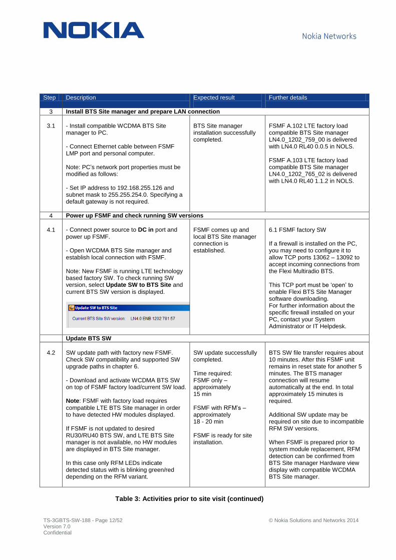
3 Install BTS Site manager and prepare LAN connection
3.1
- Install compatible WCDMA BTS Site manager to PC. - Connect Ethernet cable between FSMF LMP port and personal computer. Note: PC’s network port properties must be modified as follows: - Set IP address to 192.168.255.126 and subnet mask to 255.255.254.0. Specifying a default gateway is not required.
BTS Site manager installation successfully completed.
FSMF A.102 LTE factory load compatible BTS Site manager LN4.0_1202_759_00 is delivered with LN4.0 RL40 0.0.5 in NOLS. FSMF A.103 LTE factory load compatible BTS Site manager LN4.0_1202_765_02 is delivered with LN4.0 RL40 1.1.2 in NOLS.
4 Power up FSMF and check running SW versions
4.1
- Connect power source to DC in port and
power up FSMF. - Open WCDMA BTS Site manager and establish local connection with FSMF. Note: New FSMF is running LTE technology based factory SW. To check running SW version, select Update SW to BTS Site and
current BTS SW version is displayed.
FSMF comes up and local BTS Site manager connection is established.
6.1 FSMF factory SW If a firewall is installed on the PC, you may need to configure it to allow TCP ports 13062 – 13092 to accept incoming connections from the Flexi Multiradio BTS. This TCP port must be ‘open’ to enable Flexi BTS Site Manager software downloading. For further information about the specific firewall installed on your PC, contact your System Administrator or IT Helpdesk.
Update BTS SW
4.2
SW update path with factory new FSMF. Check SW compatibility and supported SW upgrade paths in chapter 6. - Download and activate WCDMA BTS SW on top of FSMF factory load/current SW load. Note: FSMF with factory load requires
compatible LTE BTS Site manager in order to have detected HW modules displayed. If FSMF is not updated to desired RU30/RU40 BTS SW, and LTE BTS Site manager is not available, no HW modules are displayed in BTS Site manager. In this case only RFM LEDs indicate detected status with is blinking green/red depending on the RFM variant.
SW update successfully completed. Time required: FSMF only – approximately 15 min FSMF with RFM’s – approximately 18 - 20 min FSMF is ready for site installation.
BTS SW file transfer requires about 10 minutes. After this FSMF unit remains in reset state for another 5 minutes. The BTS manager connection will resume automatically at the end. In total approximately 15 minutes is required. Additional SW update may be required on site due to incompatible RFM SW versions. When FSMF is prepared prior to system module replacement, RFM detection can be confirmed from BTS Site manager Hardware view display with compatible WCDMA BTS Site manager.
Table 3: Activities prior to site visit (continued)

TS-3GBTS-SW-188 - Page 13/52 © Nokia Solutions and Networks 2014 Version 7.0 Confidential
Step Description Expected result
Further details
5 Prepare SCF (BTS part) for FSMF – start compatible BTS Site manager
5.1
- Start BTS Site manager in ‘Create File’
mode.
- Optionally, convert FSME/D commissioning data when connected to FSMF (step 9.1).
‘Create commissioning file’ view is displayed in
BTS Site manager view.
BTS Site manager in ‘Create File’ is
referred as ‘offline conversion’. The conversion of FSME/D commissioning data for FSMF use can be also done when connected to FSMF. Both BTS and TRS parts are converted during commissioning steps. Therefore, the SCF preparation prior to site visit is optional.
Prepare SCF (BTS part) for FSMF - In ‘Introduction’ page,
5.2
- Select ‘BTS’ option as ‘Target’, select ‘Create file from existing commissioning file’ and locate previously stored backup
commissioning file of BTS Site equipped with FSME/D (Backup file consists BTS part).
With RU30 Backup commissioning file
Example: Backup SCF from WN7.0 2.0. - Select ‘Convert’ to continue BTS
commissioning file conversion to FSMF use.
With RU40 Backup commissioning file
Example: Backup SCF from WN8.0 1.0. - Select ‘Next to continue BTS
commissioning file conversion to FSMF use.
FSME/D BTS commissioning file is converted to FSMF commissioning file. FSMF TRS commissioning parameters to be manually added.
The offline conversion of FSME/D TRS commissioning file to FSMF TRS commissioning file is not supported by WCDMA BTS Site manager. TRS parameters shall be manually added while navigating through commissioning wizard. Therefore only BTS part of the SCF can be converted for FSMF use with ‘Create file’ mode. Alternatively, the conversion of FSME/D TRS commissioning data for FSMF use can be done when connected to FSMF. Both BTS and TRS parts are converted during commissioning steps. Therefore, the SCF preparation prior to site visit is optional.
Table 4: Activities prior to site visit (continued)
TS-3GBTS-SW-188 - Page 14/52 © Nokia Solutions and Networks 2014 Version 7.0 Confidential
Step Description Expected result
Further details
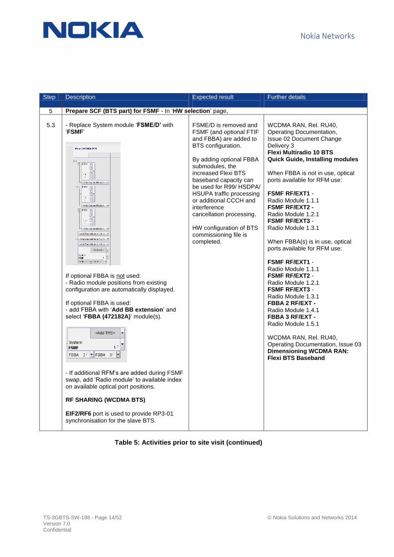
5 Prepare SCF (BTS part) for FSMF - In ‘HW selection’ page,
5.3
- Replace System module ‘FSME/D’ with ‘FSMF’
If optional FBBA is not used: - Radio module positions from existing configuration are automatically displayed.
If optional FBBA is used: - add FBBA with ‘Add BB extension’ and select ‘FBBA (472182A)’ module(s).
- If additional RFM’s are added during FSMF swap, add ‘Radio module’ to available index on available optical port positions.
RF SHARING (WCDMA BTS) EIF2/RF6 port is used to provide RP3-01
synchronisation for the slave BTS.
FSME/D is removed and FSMF (and optional FTIF and FBBA) are added to BTS configuration. By adding optional FBBA submodules, the increased Flexi BTS baseband capacity can be used for R99/ HSDPA/ HSUPA traffic processing or additional CCCH and interference cancellation processing. HW configuration of BTS commissioning file is completed.
WCDMA RAN, Rel. RU40, Operating Documentation, Issue 02 Document Change Delivery 3 Flexi Multiradio 10 BTS Quick Guide, Installing modules
When FBBA is not in use, optical ports available for RFM use: FSMF RF/EXT1 -
Radio Module 1.1.1 FSMF RF/EXT2 -
Radio Module 1.2.1 FSMF RF/EXT3 -
Radio Module 1.3.1 When FBBA(s) is in use, optical ports available for RFM use: FSMF RF/EXT1 -
Radio Module 1.1.1 FSMF RF/EXT2 -
Radio Module 1.2.1 FSMF RF/EXT3 -
Radio Module 1.3.1 FBBA 2 RF/EXT -
Radio Module 1.4.1 FBBA 3 RF/EXT -
Radio Module 1.5.1
WCDMA RAN, Rel. RU40, Operating Documentation, Issue 03 Dimensioning WCDMA RAN: Flexi BTS Baseband
Table 5: Activities prior to site visit (continued)

TS-3GBTS-SW-188 - Page 15/52 © Nokia Solutions and Networks 2014 Version 7.0 Confidential
Step Description Expected result
Further details
5 Prepare SCF (BTS part) for FSMF - In ‘BTS Settings’ page,
5.4
When external GPS synchronization is received from another BTS, In synchronization source BTS’
commissioning, - select ‘Forward synchronization in co-siting’ and ‘GPS in use’.
In chained BTS synchronization
commissioning, - select ‘GPS in use’ and ‘GPS control interface blocked for co-located BTS’.
Synchronization source/sharing is set.
In synchronization source BTS, time synchronization can be done based on GPS control data. In chained BTS, GPS control data cannot be used for time synchronization due to one way control data from synchronization source BTS. Hence, NTP is required for time synchronization. In BTS SCF, commissioning parameter ‘gpsCtrlBlockForCoLocatedBts’ is set as ‘True’ to close GPS communication port on BTS so that it does not confuse time synchronization with NTP. See 7.5.2 FSMF synchronization cables, 7.5.3 FSMF GPS feeding cables
Table 6: Activities prior to site visit (continued)
TS-3GBTS-SW-188 - Page 16/52 © Nokia Solutions and Networks 2014 Version 7.0 Confidential
Step Description Expected result
Further details
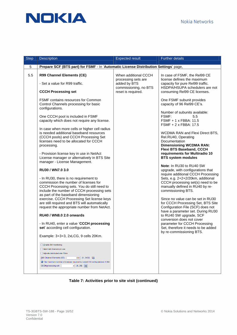
5 Prepare SCF (BTS part) for FSMF - In ‘Automatic License Distribution Settings’ page,
5.5
R99 Channel Elements (CE)
- Set a value for R99 traffic. CCCH Processing set
FSMF contains resources for Common Control Channels processing for basic configurations. One CCCH pool is included in FSMF capacity which does not require any license. In case when more cells or higher cell radius is needed additional baseband resources (CCCH pools) and CCCH Processing Set licenses need to be allocated for CCCH processing. - Provision license key in use in NetAct License manager or alternatively in BTS Site manager - License Management. RU30 / WN7.0 3.0
- In RU30, there is no requirement to commission the number of licenses for CCCH Processing sets. You do still need to include the number of CCCH processing sets as part of the baseband dimensioning exercise. CCCH Processing Set license keys are still required and BTS will automatically request the appropriate number from NetAct. RU40 / WN8.0 2.0 onwards
- In RU40, enter a value ‘CCCH processing set’ according cell configuration.
Example: 3+3+3, 2xLCG, 9 cells 20Km.
When additional CCCH processing sets are added by BTS commissioning, no BTS reset is required.
In case of FSMF, the Rel99 CE license defines the maximum capacity for pure Rel99 traffic. HSDPA/HSUPA schedulers are not consuming Rel99 CE licenses. One FSMF subunit provides capacity of 96 Rel99 CE’s. Number of subunits available: FSMF: 5.5 FSMF + 1 x FBBA: 11.5 FSMF + 2 x FBBA: 17.5 WCDMA RAN and Flexi Direct BTS, Rel.RU40, Operating Documentation Dimensioning WCDMA RAN: Flexi BTS Baseband, CCCH requirements for Multiradio 10 BTS system modules
Note: In RU30 to RU40 SW
upgrade, with configurations that require additional CCCH Processing Sets, e.g. 2+2+2/20km, additional CCCH processing set(s) need to be manually defined in RU40 by re-commissioning BTS. Since no value can be set in RU30 for CCCH Processing Set, BTS Site Configuration File (SCF) does not have a parameter set. During RU30 to RU40 SW upgrade, SCF conversion does not cover parameter for CCCH Processing Set, therefore it needs to be added by re-commissioning BTS.
Table 7: Activities prior to site visit (continued)

TS-3GBTS-SW-188 - Page 17/52 © Nokia Solutions and Networks 2014 Version 7.0 Confidential
Step Description Expected result
Further details
5 Prepare SCF (BTS part) for FSMF - In ‘WCDMA Carrier Candidates and Local Cell Group Settings’ page,
5.6
In case of BASEBAND CAPACITY CHANGE from 2 x FSME to 1 x FSMF and more than 6 cells with HSPA are present,
- select ‘Local cell groups in use’ and ‘Frequency based grouping’ or ‘Sector based grouping’ based on your
reference.
In ‘Carrier Candidate and local cell groups’,
- set ‘Local cell group’. When ‘Local cell
groups in use’ is selected, at least 2 groups must be defined. Example: 3+3+3, 2xLCG, 9 cells 20Km.
. . . Example: MultiBand 3+3+3/1+1+1, 3xLCG, 12 cells 20 Km and 3+3+3+3, 3xLCG 12 cells 20Km.
. . .
Local cells are distributed to required Local cell groups. If ‘Local cell groups in use’ is not selected, and
max. 6 cells are present, all local cells are added to Local cell group 1.
Local Cell Grouping allows
splitting available baseband capacity into baseband pools responsible for processing traffic from dedicated group of cells. Local Cell Grouping may be needed in case of BTSs with many cells, and can be used in Multi Operator RAN (MORAN). It is possible to use MORAN without Local Cell Grouping and dedicated baseband allocation. Frequency layer based commissioning
- All cells from frequency layer(s) must be dedicated to the same Local Cell Group. Sector based commissioning
- Dedication of cells from the same frequency layer(s) to different LCGs is allowed. - Dedication of cells from the same frequency layer(s) to the same LCG. In this case sector based commissioning might give the same results, as frequency layer based commissioning. WCDMA RAN and Flexi Direct BTS, Rel.RU40, Operating Documentation Dimensioning WCDMA RAN: Flexi BTS Baseband, Flexi System Module Rel.3 HSDPA scheduler
When more than 6 cells with HSPA are present, With 2 x FSME, one local cell group is defined. - 1 x LCG and 9 cells 20Km. With 1 x FSMF, at least 2 LCG’s must be defined - 2 x LCG and 9 cells 20Km, - 3 x LCG and 12 cells 20Km.
Table 8: Activities prior to site visit (continued)

TS-3GBTS-SW-188 - Page 18/52 © Nokia Solutions and Networks 2014 Version 7.0 Confidential
Step Description Expected result
Further details
5 Prepare SCF (BTS part) for FSMF (continued) - In ‘WCDMA Carrier Candidates and Local Cell Group Settings’ page,
5.6
In ‘Baseband (BB) and HSPA license allocations’,
- set BB and HSPA license allocation values according Local Cell Group preference. Example: 3+3+3, 2xLCG, 9 cells 20Km.
Example: MultiBand 3+3+3/1+1+1, 3xLCG 12 cells 20 Km and 3+3+3+3, 3xLCG, 12 cells 20Km.
In ‘Mapping HSPA local cells to baseband HW and Parallel Interference Cancellation (PIC),
- set ‘PIC pools’ starting from lowest number
available and select ‘Next’ to continue. Example: 3+3+3, 2xLCG, 9 cells 20Km.
Example: MultiBand 3+3+3/1+1+1 3xLCG, 12 cells 20Km and 3+3+3+3, 3xLCG, 12 cells 20Km.
BB/HSPA license allocation and optional PIC pools are set. If ‘Local cell groups in use’ is not selected, BB
and HSPA license allocation and PIC pool setting is not available.
WCDMA RAN and Flexi Direct BTS, Rel.RU40, Operating Documentation Dimensioning WCDMA RAN: Flexi BTS Baseband, Flexi System Module Rel.3 HSDPA scheduler
When more than 6 cells with HSPA are present, for example 3+3+3 and Multi Band 3+3+3/1+1+1 configuration With 2 x FSME, one local cell group is defined. - 1 x LCG and 9 cells 20Km. With 1 x FSMF, at least 2 LCG’s must be defined - 2 x LCG and 9 cells 20Km, - 3 x LCG and 12 cells 20Km. The maximum available baseband capacity of FSMF for pure traffic depends on - Local Cell Group (LCG) - configuration type - Additional CCCH processing resources (if needed) - Number of activated Interference Cancellation units (PIC pools) - HSUPA static resources (optional static reservation for HSUPA data/voice users) and - HS_Cell_FA CH_UL static resources (optional static reservation for HS-FA CH UL users). RAN1308 HSUPA Interference Cancellation Receiver
If PIC Pool is not in use, on RNC side edit the ‘AdminPicState’ in to ‘Disabled’ under Admission Control tab.
Table 9: Activities prior to site visit (continued)

TS-3GBTS-SW-188 - Page 19/52 © Nokia Solutions and Networks 2014 Version 7.0 Confidential
Step Description Expected result
Further details
5 Prepare SCF (BTS part) for FSMF - In ‘HSDPA Settings’ page,
5.7
Include adequate amount of ‘HSDPA capacity sets’ in order to get throughput
allocated as per BTS Site preference.
- set ‘BTS processing set 1/2/3‘ according
BTS Site preferences.
HSDPA BTS processing set capacities:
HSDPA BTS processing set 1 - 32 users and 7.2Mbps HSDPA BTS processing set 2 - 72 users and 21Mbps HSDPA BTS processing set 3 - 72 users and 84Mbps.
Example: 3+3+3, 2xLCG, 9 cells 20Km,
In total, 1 x 21 + 2 x 84 Mbps = 189Mbps of licensed capacity available for all schedulers.
Scheduler licensed throughputs are calculated as per given formula (scheduler throughput steps from step 5.8) Scheduler 1 - LCG 1 = Round down {(1 + 4*2) * (12 /(12+6+6+3)) } * 21 Mbps = 84 Mbps
Scheduler 2 - LCG 1 = Round down {(1 + 4*2) * (6 /(12+6+6+3)) } * 21 Mbps = 42 Mbps
Scheduler 1 - LCG 2 = Round down {(1 + 4*2) * (6 /(12+6+6+3)) } * 21 Mbps = 42 Mbps
Scheduler 2 - LCG 2 = Round down {(1 + 4*2) * (3 /(12+6+6+3)) } * 21 Mbps = 21 Mbps
HSDPA processing set(s) are commissioned.
The HSDPA BTS processing set describes the maximum HSDPA capability that allows reaching a certain number of HSDPA users and DL throughput WCDMA RAN and Flexi Direct BTS, Rel.RU40, Operating Documentation Dimensioning WCDMA RAN: Flexi BTS Baseband, Flexi System Module Rel.3 HSDPA scheduler
Formula for scheduler licensed throughput:
If there are only HSDPA Processing Set 2 and three licenses are present in BTS, the division of licensed throughput will be done for each scheduler according to the formula below:
Scheduler_licensed_throughput = Round_down { (Number_of_HSDPA_Processing_Sets_2 + 4* Number_of_HSDPA_Processing_Sets_3) * (Scheduler_HSDPA_throughput_step / Total_number_of_HSDPA_throughput_step_per_BTS) } * 21 Mbps
If after calculations presented above throughput for all schedulers is lower than total licensed throughput in the BTS, the remaining throughput is distributed between activated schedulers.
Schedulers are prioritized in the following order:
a) Scheduler with lowest value of licensed throughput divided by commissioned throughput; b) Schedulers belonging to LCG with the lowest ID (in case of Normal HSPA configuration where 2 HSDPA schedulers activated, scheduler#1 is prioritized over scheduler#2).
Table 10: Activities prior to site visit (continued)

TS-3GBTS-SW-188 - Page 20/52 © Nokia Solutions and Networks 2014 Version 7.0 Confidential
Step Description Expected result
Further details
5 Prepare SCF (BTS part) for FSMF - In ‘HSDPA Throughput Settings’ page,
5.8
In ‘HSPA setting’,
- select HSPA configuration (HSPA setting)
option according LCG throughput requirements.
In ‘HSDPA throughput’,
- select a value according Local Cell Group requirements.
This setting is optional. If ‘Max throughput’ is left as ‘System default’, then 84Mbps is
allocated to every 1-6 non-MIMO cells.
In case BASEBAND CAPACITY CHANGE from 2 x FSME to1 x FSMF and more than 6 cells with HSPA are present,
- select ‘HSDPA throughput’ according
Local Cell Group preference. Each HSDPA throughput step corresponds to 7.2Mbps. Example: 3+3+3, 2xLCG, 9 cells 20Km.
Optional HSPA setting is selected and HSDPA throughput steps are selected.
There are three LCG configuration types available for FSMF which describes HSPA capability (number of HSPA supported cells and number of HSDPA/HSUPA schedulers). Rel.99 only configuration
Max number of supported cells = 12 Max number of HSPA cells = 6 Number of HSDPA schedulers = 0 Small HSPA configuration
Max number of supported cells = 6 Max number of HSPA cells = 6 Number of HSDPA schedulers = 1 Normal HSPA configuration
Max number of supported cells = 12 Max number of HSPA cells = 12 Number of HSDPA schedulers = 2 The LCG configuration type is set during B TS commissioning for each LCG separately using HSPA setting parameter. If not commissioned then ‘Normal HSPA’ configuration is assumed by default. WCDMA RAN and Flexi Direct BTS, Rel.RU40, Operating Documentation Dimensioning WCDMA RAN: Flexi BTS Baseband, Flexi System Module Rel.3 HSDPA scheduler
The scheduler provides HSDPA throughput, which depends on activated features, number and type of BTS processing sets, and HSDPA throughput commissioning by the operator. The HSDPA throughput step has No impact on HSDPA baseband capacity allocation but it is used for HSDPA licensed throughput distribution among available schedulers. In addition it can be used to limit HSDPA scheduler throughput.
Table 11: Activities prior to site visit (continued)

TS-3GBTS-SW-188 - Page 21/52 © Nokia Solutions and Networks 2014 Version 7.0 Confidential
Step Description Expected result
Further details
5 Prepare SCF (BTS part) for FSMF - In ‘Summary’ page,
5.9
- Navigate through commissioning steps to ‘Summary’ view and save BTS
commissioning file. After saving BTS commissioning file, the following popup is shown.
- Select ‘Define new configuration’ to
create TRS commissioning file next. TRS commissioning file can also be created by starting the BTS Site manager again in Create File – mode (see 5.1).
BTS commissioning file is ready. TRS commissioning file to be prepared next.
Table 12: Activities prior to site visit (continued)

TS-3GBTS-SW-188 - Page 22/52 © Nokia Solutions and Networks 2014 Version 7.0 Confidential
Step Description Expected result
Further details
6 Prepare SCF (TRS part) for FSMF - In ‘Introduction’ page,
6.1
- Select ‘TRS’ option as ‘Target’, continue with ‘Next’.
- Optionally, convert the FSME/D commissioning data when connected to FSMF (step 9.1).
Existing FSME/D TRS commissioning file cannot be used in offline conversion (with ‘Create File’ –mode). FSMF TRS commissioning file parameters need to be manually added. Therefore, open previously stored snapshot with offline BTS Site manager to view TRS parameters. And copy them accordingly to FSMF TRS commissioning. The conversion of FSME/D TRS commissioning data for FSMF use can be done when connected to FSMF. Both BTS and TRS parts are converted during commissioning steps. Therefore, the SCF preparation prior to site visit is optional.
Prepare SCF (TRS part) for FSMF - In ‘HW selection’ page,
6.2
Optional FTIF is not used: - Select ‘Add TRS’ and choose ‘FSMx rel3’.
Optional FTIF is used: - Select ‘Add TRS’ and choose ‘FTIF’.
Snapshot can be viewed with offline BTS Site manager while setting TRS parameters for FSMF commissioning. TRS commissioning files can be viewed with compatible BTS Site manager in ‘Create file’ mode.
Table 13: Activities prior to site visit (continued)

TS-3GBTS-SW-188 - Page 23/52 © Nokia Solutions and Networks 2014 Version 7.0 Confidential
Step Description Expected result
Further details
6 Prepare SCF (TRS part) for FSMF - In ‘Site Properties’ page,
6.3
Site specific IP configuration is different between FSME/D and FSMF. With FSMF, ‘BTS IP address is not displayed and therefore it is not needed. - Set ‘TRS’, ’RNC’ and ‘NTP’ IP addresses.
Furthermore, BTS commissioning file does not have ‘btsIpAddr’ name element
instance. - Continue to navigate through commissioning steps and copy parameters accordingly from previously saved TRS commissioning file or snapshot.
Table 14: Activities prior to site visit (continued)

TS-3GBTS-SW-188 - Page 24/52 © Nokia Solutions and Networks 2014 Version 7.0 Confidential
Step Description Expected result
Further details
6 Prepare SCF (TRS part) for FSMF – In ‘Physical Layer Configuration’ page
6.4
Define Ethernet interface which will be used for Iub connectivity.
Optional FTIF module not used: - Select transport interface EIF port:
EIF1 – FSM 1 or EIF2 – FSM 2.
Optional FTIF module used: - Select transport interface EIF port:
EIF 3 - FTIF 3 or EIF 4 - FTIF 4.
RF SHARING (WCDMA BTS) - Select ‘Enable FSM EIF2 as RP3-01 interface’ for slave BTS synchronisation use.
Port ‘OPT-EXT1’ (Radio Module 1.4.1) of FSME/D is used for slave BTS synchronisation in RF sharing. With FSMF slave BTS synchronisation is routed through EIF2/RF6 port.
WCDMA RAN, Rel. RU40, Operating Documentation, Issue 02, Documentation Change Delivery 3 RU40 Feature Descriptions and Instructions - 4.2 RAN2296: FTIF Eth+E1/T1/JT1 for Flexi Multiradio System Module
Table 15: Activities prior to site visit (continued)
TS-3GBTS-SW-188 - Page 25/52 © Nokia Solutions and Networks 2014 Version 7.0 Confidential
Step Description Expected result
Further details
6 Prepare SCF (TRS part) for FSMF - In ‘Summary’ page,
6.5
- Continue to navigate through commissioning steps to ‘Summary’ page
and save TRS commissioning file.
TRS commissioning file is ready.
BTS and TRS commissioning files are both ready.
Table 16: Activities prior to site visit (continued)
7.4 Steps during to site visit
Step Description Expected result
Further details
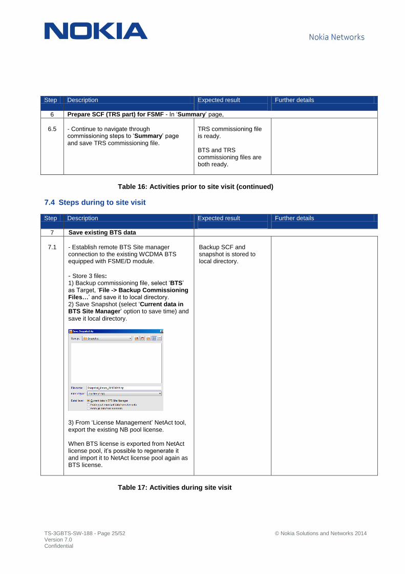
7 Save existing BTS data
7.1
- Establish remote BTS Site manager connection to the existing WCDMA BTS equipped with FSME/D module.
- Store 3 files: 1) Backup commissioning file, select ‘BTS’ as Target, ‘File -> Backup Commissioning Files…’ and save it to local directory. 2) Save Snapshot (select ‘Current data in BTS Site Manager’ option to save time) and
save it local directory.
3) From ‘License Management’ NetAct tool, export the existing NB pool license. When BTS license is exported from NetAct license pool, it’s possible to regenerate it and import it to NetAct license pool again as BTS license.
Backup SCF and snapshot is stored to local directory.
Table 17: Activities during site visit

TS-3GBTS-SW-188 - Page 26/52 © Nokia Solutions and Networks 2014 Version 7.0 Confidential
Step Description Expected result
Further details
7 HW replacement
7.2
- Power down FSME/D, disconnect all
cabling & SFP modules from system module and remove it from rack. Note: FSME/D as an Extension System module cannot be used with FSMF until
further notice. - Equip FSMF with optional sub-modules
according to the target BTS site requirements. Do not mix FPFD and FTIF interconnection plug-in cards. FTIF interconnection plug-in card is labeled with ‘FSM’ and ‘TRS’. FPFD plug-in card is labeled with ‘Power unit FPFD’.
- Install FSMF core loosely inside the casing. Cabling is only possible when FSMF is loosely fitted to casing.
FSME/D System module(s) is removed BTS Site. FSMF with optional sub-module(s) is replaced to BTS Site.
WCDMA RAN, Rel. RU40, Operating Documentation, Issue 03 - Flexi Multiradio 10 BTS Quick Guide, Installing optional sub-modules
Table 18: Activities during site visit (continued)

TS-3GBTS-SW-188 - Page 27/52 © Nokia Solutions and Networks 2014 Version 7.0 Confidential
Step Description Expected result
Further details
7 FSMF power feeding
7.3
If optional FPFD is not used: - Connect external power source for FSMF directly to DC in connector.
If optional FPFD is used: - Connect power source to FPFD power
distribution unit installed together with FSMF. Use correct interconnection plug-in card provided with FPFD unit. - Strip DC input cables exactly to 16mm
before fitting them. Ensure that cables are securely fitted to FPFD main terminal.
FSMF power cabling completed.
WCDMA RAN, Rel. RU40, Operating Documentation, Issue 03 - Flexi Multiradio 10 BTS Quick Guide, Cabling, Connecting external power feed
RFM power feeding from FSMF
7.4
- Remove rubber boot and connector from the existing RFM power cable. - Strip exactly to 10mm. - Connect RFM cables to FPFD DC output terminals in the following recommended
order: FPFD RF1 Radio Module 1.1.1 FPFD RF2 Radio Module 1.2.1 FPFD RF3 Radio Module 1.3.1 FPFD EXT Radio Module 1.x.x FSMF DC out FBBA 2 (and FBBA 3) powered from FBBA 2)
Maximum power consumption of DC outputs: FPFD RF1 1100W FPFD RF2 1100W FPFD RF3 1100W FPFD EXT 1100W FSMF DC out 600W
Over current protection of DC outputs: FPFD RF1 31.0A ± 5% FPFD RF2 31.0A ± 5% FPFD RF3 31.0A ± 5% FPFD EXT 31.0A ± 5% FSMF DC out 18.0A ± 5%
RFM power cabling completed.
WCDMA RAN, Rel. RU40, Operating Documentation, Issue 03 - Flexi Multiradio 10 BTS Quick Guide, Cabling, Connecting external power feed
Instead of the existing power cables, consider using the following cable options: FPCB 472817A is a 2 m (6.6 ft)
single DC power cable with connectors and IP seals on both ends. If it is used with FSMF, the connector and rubber boot needs to be removed from one end. FPCC 472823A is a 2 m (6.6 ft)
single DC power cable with a connector on one end and open on the other end.
Table 19: Activities during site visit (continued)

TS-3GBTS-SW-188 - Page 28/52 © Nokia Solutions and Networks 2014 Version 7.0 Confidential
Step Description Expected result
Further details
7 Installing optional Flexi Power module/battery backup
7.5
FSMF Site support interface is LMP
connector. The same connector is used for local BTS Site manager connection. FSME/D has separate connector for site support interface port. If LMP port is required for Site support interface and intelligent shutdown is used,
- Connect RJ45 alarm cable from FPMA Flexi power module (FPAA/FPBA/FPBB) to FSMF LMP connector. - In commissioning, select ‘Flexi Power Module’.
2 EAC lines are reserved for FPMA use. One line for FPAA/FPBA/FPBB alarm and second line for ‘Mains breakdown’ alarm that is controlling intelligent shutdown feature.
If LMP port is required for local BTS management use and intelligent shutdown
feature is used, - In commissioning, select ‘Other BBU’ and define ‘External Fault Line ID’. Mains
breakdown alarm line is connected to this External Fault Line.
- Modify battery backup alarm cable and connect it to EAC box screw terminal accordingly.
Battery backup cabling completed. FPMA/NSN BBU/Other BBU is connected to BTS with appropriate FSMF EAC cable and FSEA/ FSEB/Other EAC box.
WCDMA RAN, Rel. RU40, Operating Documentation, Issue 03 - Installing Flexi Multiradio Base Station and Flexi Multiradio 10 Base Station Optional Items, Installing Flexi Power Module (FPMA)
WCDMA RAN, Rel. RU40, Operating Documentation, Issue 03 - Installing Flexi Multiradio Base Station and Flexi Multiradio 10 Base Station Optional Items, Installing Flexi System External Alarm (FSEB)
7.5.4 FSMF EAC cables 7.5.10 FSMF LMP connector pin map
Table 20: Activities during site visit (continued)
TS-3GBTS-SW-188 - Page 29/52 © Nokia Solutions and Networks 2014 Version 7.0 Confidential
Step Description Expected result
Further details
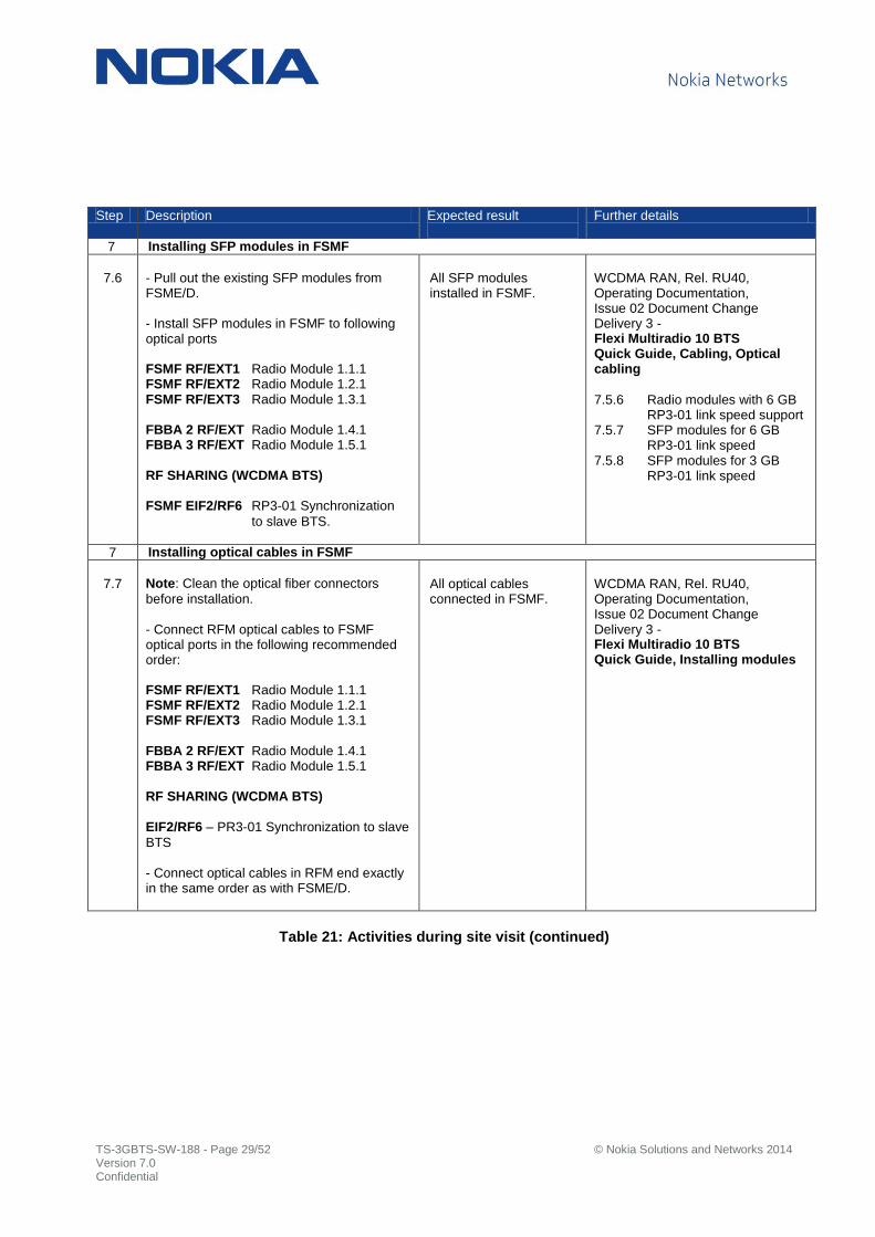
7 Installing SFP modules in FSMF
7.6
- Pull out the existing SFP modules from FSME/D. - Install SFP modules in FSMF to following optical ports FSMF RF/EXT1 Radio Module 1.1.1 FSMF RF/EXT2 Radio Module 1.2.1 FSMF RF/EXT3 Radio Module 1.3.1 FBBA 2 RF/EXT Radio Module 1.4.1 FBBA 3 RF/EXT Radio Module 1.5.1
RF SHARING (WCDMA BTS)
FSMF EIF2/RF6 RP3-01 Synchronization
to slave BTS.
All SFP modules installed in FSMF.
WCDMA RAN, Rel. RU40, Operating Documentation, Issue 02 Document Change Delivery 3 - Flexi Multiradio 10 BTS Quick Guide, Cabling, Optical cabling
7.5.6 Radio modules with 6 GB RP3-01 link speed support 7.5.7 SFP modules for 6 GB RP3-01 link speed 7.5.8 SFP modules for 3 GB RP3-01 link speed
7 Installing optical cables in FSMF
7.7
Note: Clean the optical fiber connectors
before installation. - Connect RFM optical cables to FSMF optical ports in the following recommended order: FSMF RF/EXT1 Radio Module 1.1.1 FSMF RF/EXT2 Radio Module 1.2.1 FSMF RF/EXT3 Radio Module 1.3.1
FBBA 2 RF/EXT Radio Module 1.4.1 FBBA 3 RF/EXT Radio Module 1.5.1
RF SHARING (WCDMA BTS)
EIF2/RF6 – PR3-01 Synchronization to slave
BTS - Connect optical cables in RFM end exactly in the same order as with FSME/D.
All optical cables connected in FSMF.
WCDMA RAN, Rel. RU40, Operating Documentation, Issue 02 Document Change Delivery 3 - Flexi Multiradio 10 BTS Quick Guide, Installing modules
Table 21: Activities during site visit (continued)
TS-3GBTS-SW-188 - Page 30/52 © Nokia Solutions and Networks 2014 Version 7.0 Confidential
Step Description Expected result
Further details
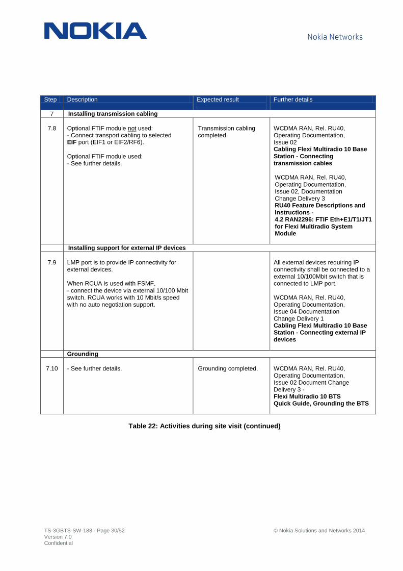
7 Installing transmission cabling
7.8
Optional FTIF module not used: - Connect transport cabling to selected EIF port (EIF1 or EIF2/RF6).
Optional FTIF module used: - See further details.
Transmission cabling completed.
WCDMA RAN, Rel. RU40, Operating Documentation, Issue 02 Cabling Flexi Multiradio 10 Base Station - Connecting transmission cables
WCDMA RAN, Rel. RU40, Operating Documentation, Issue 02, Documentation Change Delivery 3 RU40 Feature Descriptions and Instructions - 4.2 RAN2296: FTIF Eth+E1/T1/JT1 for Flexi Multiradio System Module
Installing support for external IP devices
7.9
LMP port is to provide IP connectivity for external devices. When RCUA is used with FSMF, - connect the device via external 10/100 Mbit switch. RCUA works with 10 Mbit/s speed with no auto negotiation support.
All external devices requiring IP connectivity shall be connected to a external 10/100Mbit switch that is connected to LMP port. WCDMA RAN, Rel. RU40, Operating Documentation, Issue 04 Documentation Change Delivery 1 Cabling Flexi Multiradio 10 Base Station - Connecting external IP devices
Grounding
7.10
- See further details. Grounding completed.
WCDMA RAN, Rel. RU40, Operating Documentation, Issue 02 Document Change Delivery 3 - Flexi Multiradio 10 BTS Quick Guide, Grounding the BTS
Table 22: Activities during site visit (continued)

TS-3GBTS-SW-188 - Page 31/52 © Nokia Solutions and Networks 2014 Version 7.0 Confidential
Step Description Expected result
Further details
7 Other cabling
7.11
If GPS receiver is used for synchronization: - Connect GPS cable to Sync in port.
If Sync In/Out ports are used: - Connect FSMF specific sync cable(s) to Sync In and/or Sync Out ports.
If EAC fault lines are used: - Connect FSMF specific EAC cable to EAC
port. Note: FSMF supports only 12 EAC lines.
If External Control lines 1….6 are used then External fault lines 7…12 cannot be configured in use. If EAC control lines are used:
- Existing EAC commissioning and actual
cabling configuration may need to be reconfigured.
All cabling completed. BTS hardware configuration ready for SW update.
WCDMA RAN, Rel. RU40, Operating Documentation, Issue 03 Cabling Flexi Multiradio 10 Base Station - Connecting Sync Out cable & Connecting Sync In cable
WCDMA RAN, Rel. RU40, Operating Documentation, Issue 03 Installing Flexi Multiradio Base Station and Flexi Multiradio 10 Base Station Optional Items - Installing GPS Antenna Kit (FYGA) or GPS GLONASS Receiver Antenna (FYGB)
WCDMA RAN, Rel. RU40, Operating Documentation, Issue 03 Cabling Flexi Multiradio 10 Base Station - Connecting External Alarms and Controls (EAC) cable
7.5.2 FSMF synchronization cables 7.5.3 FSMF GPS feeding cables 7.5.3 FSMF EAC cables 7.5.4 FSMF EAC signal and pin assignment
Table 23: Activities during site visit (continued)
TS-3GBTS-SW-188 - Page 32/52 © Nokia Solutions and Networks 2014 Version 7.0 Confidential
Step Description Expected result
Further details
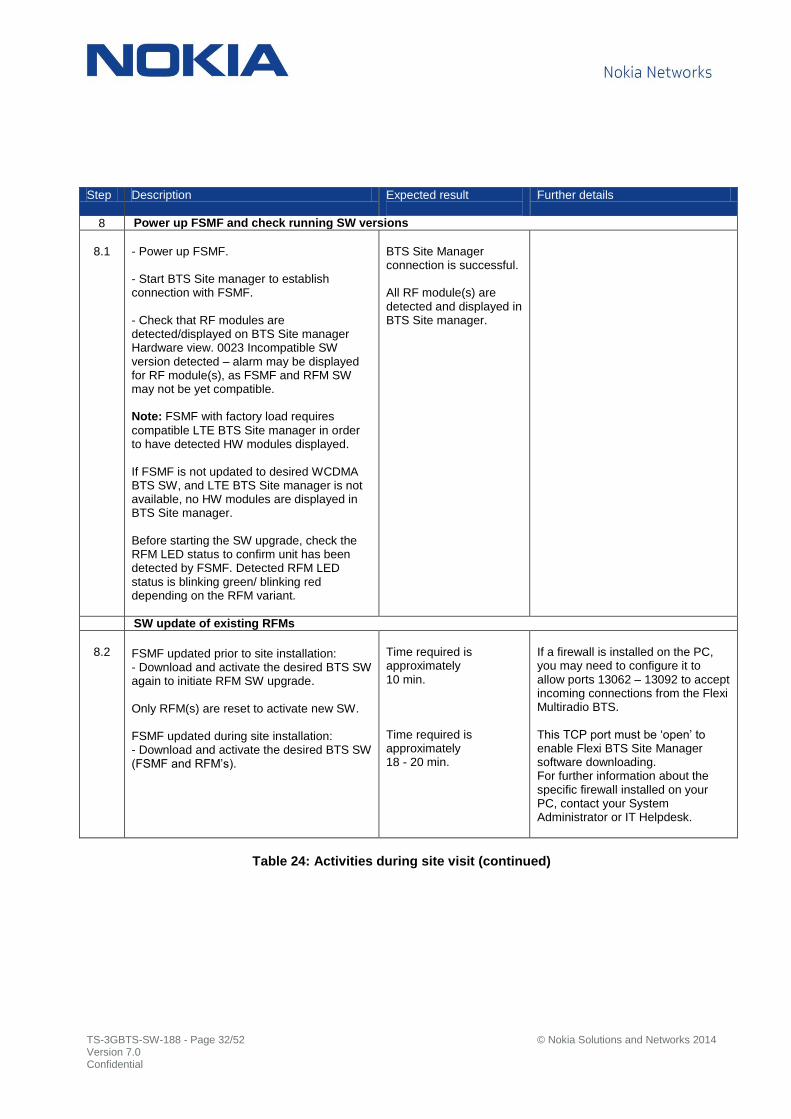
8 Power up FSMF and check running SW versions
8.1
- Power up FSMF. - Start BTS Site manager to establish connection with FSMF. - Check that RF modules are detected/displayed on BTS Site manager Hardware view. 0023 Incompatible SW version detected – alarm may be displayed for RF module(s), as FSMF and RFM SW may not be yet compatible. Note: FSMF with factory load requires
compatible LTE BTS Site manager in order to have detected HW modules displayed. If FSMF is not updated to desired WCDMA BTS SW, and LTE BTS Site manager is not available, no HW modules are displayed in BTS Site manager. Before starting the SW upgrade, check the RFM LED status to confirm unit has been detected by FSMF. Detected RFM LED status is blinking green/ blinking red depending on the RFM variant.
BTS Site Manager connection is successful. All RF module(s) are detected and displayed in BTS Site manager.
SW update of existing RFMs
8.2
FSMF updated prior to site installation: - Download and activate the desired BTS SW again to initiate RFM SW upgrade. Only RFM(s) are reset to activate new SW. FSMF updated during site installation: - Download and activate the desired BTS SW (FSMF and RFM’s).
Time required is approximately 10 min. Time required is approximately 18 - 20 min.
If a firewall is installed on the PC, you may need to configure it to allow ports 13062 – 13092 to accept incoming connections from the Flexi Multiradio BTS. This TCP port must be ‘open’ to enable Flexi BTS Site Manager software downloading. For further information about the specific firewall installed on your PC, contact your System Administrator or IT Helpdesk.
Table 24: Activities during site visit (continued)

TS-3GBTS-SW-188 - Page 33/52 © Nokia Solutions and Networks 2014 Version 7.0 Confidential
Step Description Expected result
Further details
9 Template commissioning - In ‘Introduction’ page
9.1
TEMPLATE COMMISSIONING Choose this option to convert BTS and TRS commissioning parameters when connected to FSMF BTS Site. - Select FSME/D backup commissioning file and proceed with ‘Next’.
With RU30 Backup commissioning file
Example: Backup SCF from WN7.0 2.0. - Select ‘Convert’ to continue BTS
commissioning file conversion to FSMF use.
- Select ‘Convert’ to continue TRS
commissioning file conversion to FSMF use.
- Continue to navigate through commissioning steps.
TRS parameter conversion is supported for Transport units equipped with both PDH & Ethernet interfaces (FTIA, FTJA, FTIA, FTIB, FTLB and FTFA, FTFB).
Table 25: Activities during site visit (continued)
TS-3GBTS-SW-188 - Page 34/52 © Nokia Solutions and Networks 2014 Version 7.0 Confidential
Step Description Expected result
Further details
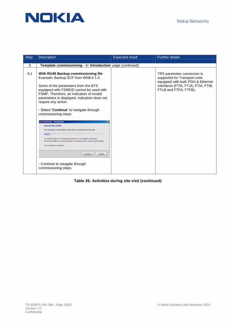
9 Template commissioning - In ‘Introduction’ page (continued)
9.1
With RU40 Backup commissioning file
Example: Backup SCF from WN8.0 1.0. Some of the parameters from the BTS equipped with FSME/D cannot be used with FSMF. Therefore, an indication of invalid parameters is displayed. Indication does not require any action. - Select ‘Continue’ to navigate through
commissioning steps.
- Continue to navigate through commissioning steps.
TRS parameter conversion is supported for Transport units equipped with both PDH & Ethernet interfaces (FTIA, FTJA, FTIA, FTIB, FTLB and FTFA, FTFB).
Table 26: Activities during site visit (continued)

TS-3GBTS-SW-188 - Page 35/52 © Nokia Solutions and Networks 2014 Version 7.0 Confidential
Step Description Expected result
Further details
9 Template commissioning - In ‘Site Properties’ page
9.2
Site specific IP configuration is different between FSME/D and FSMF. With FSMF, ‘BTS IP address is not displayed and therefore it is not needed. - Set ‘TRS’, ’RNC’ and ‘NTP’ IP addresses.
Furthermore, BTS commissioning file does not have ‘btsIpAddr’ name element
instance. - Continue to navigate through commissioning steps and copy parameters accordingly from previously saved TRS commissioning file or snapshot.
Table 27: Activities during site visit (continued)

TS-3GBTS-SW-188 - Page 36/52 © Nokia Solutions and Networks 2014 Version 7.0 Confidential
Step Description Expected result
Further details
9 Template commissioning - In ‘Physical Layer Configuration’ page
9.3
Optional FTIF module not used:
SCF conversion does not automatically select any Ethernet port in use, therefore - Select Ethernet port which will be used for Iub connectivity, EIF1 – FSM 1 or EIF2/RF6 – FSM 2).
RF SHARING (WCDMA BTS)
Port ‘OPT-EXT1’ (Radio Module 1.4.1) of FSME/D is used for slave BTS synchronisation in RF sharing. With FSMF slave BTS synchronisation is routed through EIF2/RF6 port. - Select ‘Enable FSM EIF2 as RP3-01 interface’ for slave BTS synchronisation use.
- Navigate through commissioning steps and make necessary changes if required (all values are as expected as a default). - Save commissioning file and ‘Send parameters’ to activate new commissioning
Table 28: Activities during site visit (continued)
TS-3GBTS-SW-188 - Page 37/52 © Nokia Solutions and Networks 2014 Version 7.0 Confidential
Step Description Expected result
Further details
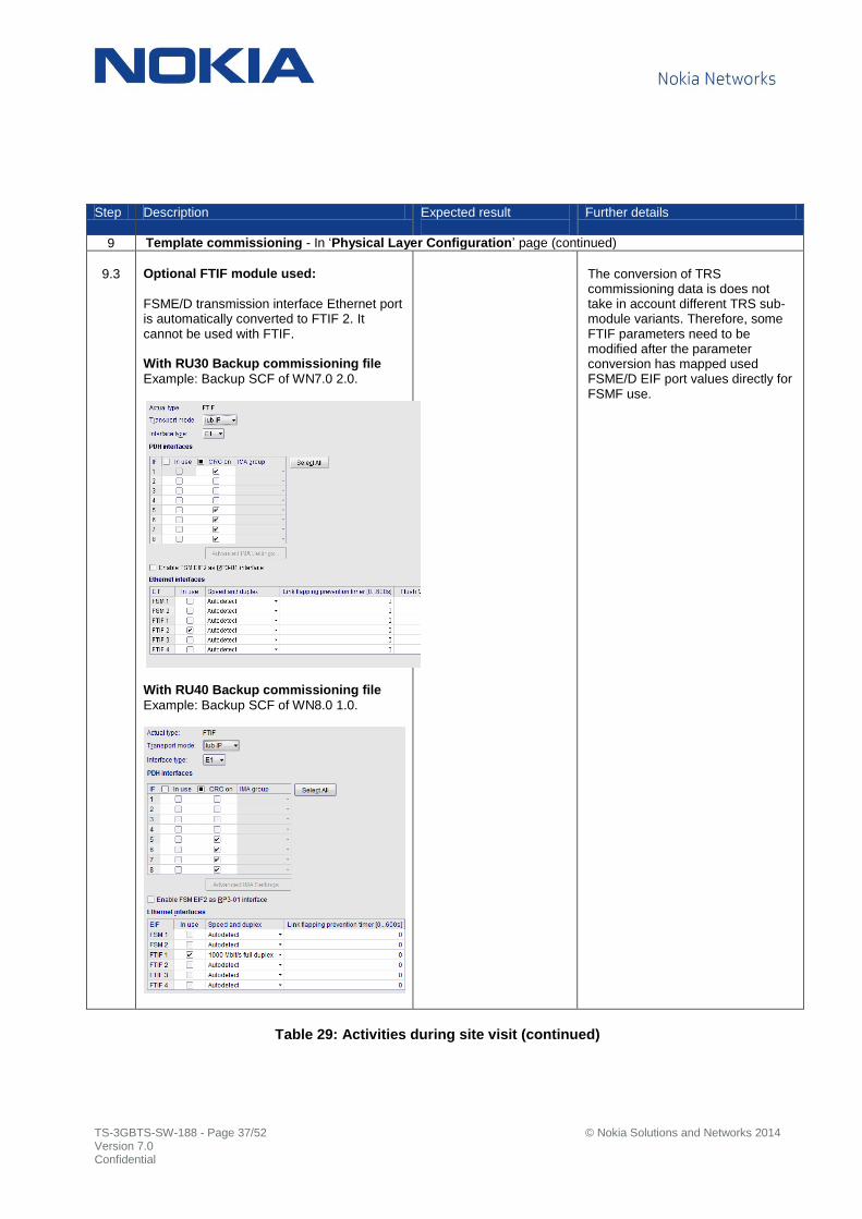
9 Template commissioning - In ‘Physical Layer Configuration’ page (continued)
9.3
Optional FTIF module used:
FSME/D transmission interface Ethernet port is automatically converted to FTIF 2. It cannot be used with FTIF. With RU30 Backup commissioning file
Example: Backup SCF of WN7.0 2.0.
With RU40 Backup commissioning file
Example: Backup SCF of WN8.0 1.0.
The conversion of TRS commissioning data is does not take in account different TRS sub-module variants. Therefore, some FTIF parameters need to be modified after the parameter conversion has mapped used FSME/D EIF port values directly for FSMF use.
Table 29: Activities during site visit (continued)
TS-3GBTS-SW-188 - Page 38/52 © Nokia Solutions and Networks 2014 Version 7.0 Confidential
Step Description Expected result
Further details
9 Template commissioning - In ‘Synchronization’ page
9.4
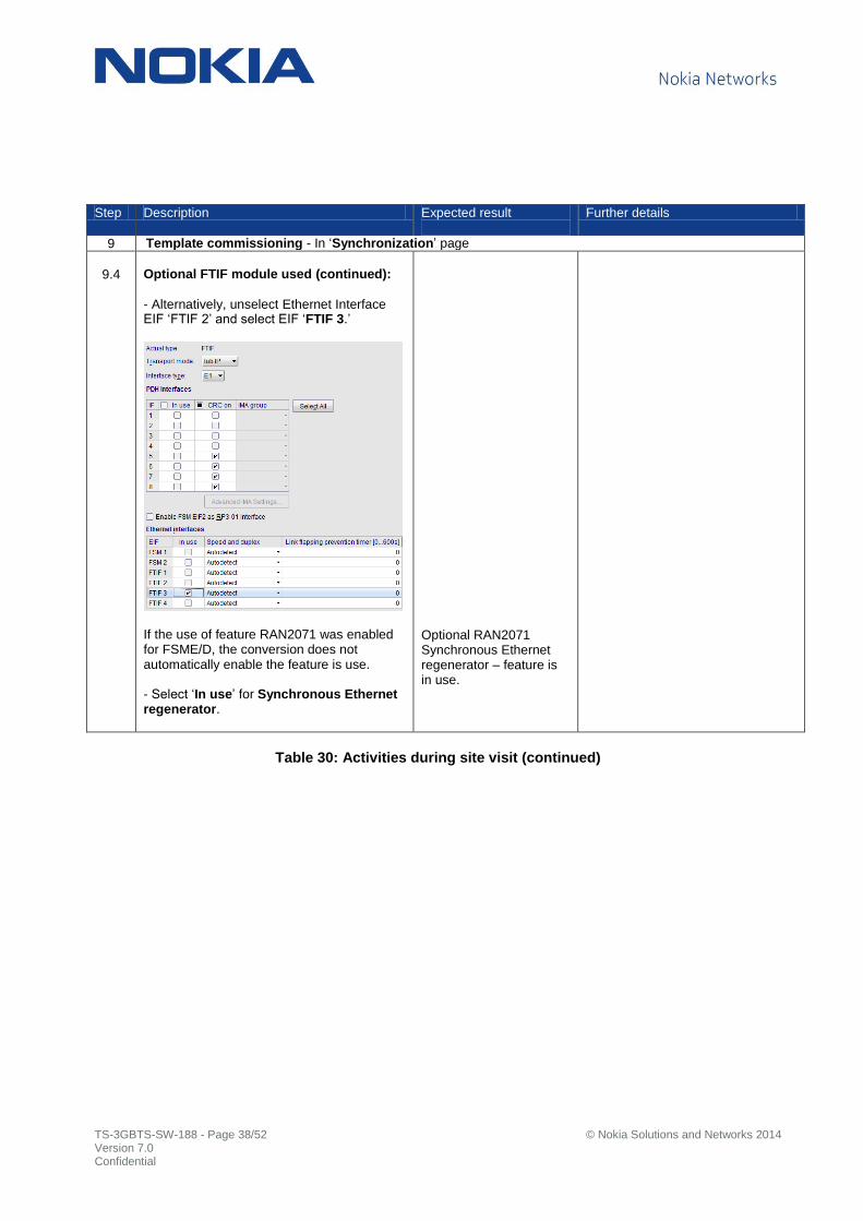
Optional FTIF module used (continued):
- Alternatively, unselect Ethernet Interface EIF ‘FTIF 2’ and select EIF ‘FTIF 3.’
If the use of feature RAN2071 was enabled for FSME/D, the conversion does not automatically enable the feature is use. - Select ‘In use’ for Synchronous Ethernet regenerator.
Optional RAN2071 Synchronous Ethernet regenerator – feature is in use.
Table 30: Activities during site visit (continued)

TS-3GBTS-SW-188 - Page 39/52 © Nokia Solutions and Networks 2014 Version 7.0 Confidential
Step Description Expected result
Further details
9 Template commissioning - In ‘Automatic Licence Distribution Settings’
9.5
R99 Channel Elements (CE)
- Set a value for R99 traffic. CCCH Processing set
FSMF contains resources for Common Control Channels processing for basic configurations. One CCCH pool is included in FSMF capacity which does not require any license. In case when more cells or higher cell radius is needed additional baseband resources (CCCH pools) and CCCH Processing Set licenses need to be allocated for CCCH processing. - Provision license key in use in NetAct License manager or alternatively in BTS Site manager - License Management. RU30 / WN7.0 3.0
- In RU30, there is no requirement to commission the number of licenses for CCCH Processing sets. You do still need to include the number of CCCH processing sets as part of the baseband dimensioning exercise. CCCH Processing Set license keys are still required and BTS will automatically request the appropriate number from NetAct. RU40 / WN8.0 2.0 onwards
- In RU40, enter a value ‘CCCH processing set’ according cell configuration.
Example: 3+3+3, 2xLCG, 9 cells 20Km. 2 CCCH processing sets required.
When additional CCCH processing sets are added by BTS commissioning, no BTS reset is required. R99 CE’s and CCCH processing set(s) are defined.
In case of FSMF, the Rel99 CE license defines the maximum capacity for pure Rel99 traffic. HSDPA/HSUPA schedulers are not consuming Rel99 CE licenses. One FSMF subunit provides capacity of 96 Rel99 CE’s. Number of subunits available: FSMF: 5.5 FSMF + 1 x FBBA: 11.5 FSMF + 2 x FBBA: 17.5 WCDMA RAN and Flexi Direct BTS, Rel.RU40, Operating Documentation Dimensioning WCDMA RAN: Flexi BTS Baseband, CCCH requirements for Multiradio 10 BTS system modules
Note: In RU30 to RU40 SW
upgrade, with configurations that require additional CCCH Processing Sets, e.g. 2+2+2/20km, additional CCCH processing set(s) need to be manually defined in RU40 by re-commissioning BTS. Since no value can be set in RU30 for CCCH Processing Set, BTS Site Configuration File (SCF) does not have a parameter set. During RU30 to RU40 SW upgrade, SCF conversion does not cover parameter for CCCH Processing Set, therefore it needs to be added by re-commissioning BTS.
Table 31: Activities during site visit (continued)
TS-3GBTS-SW-188 - Page 40/52 © Nokia Solutions and Networks 2014 Version 7.0 Confidential
Step Description Expected result
Further details
9 Template commissioning - In ‘WCDMA Carrier Candidates and Local Cell Group Settings’ page,
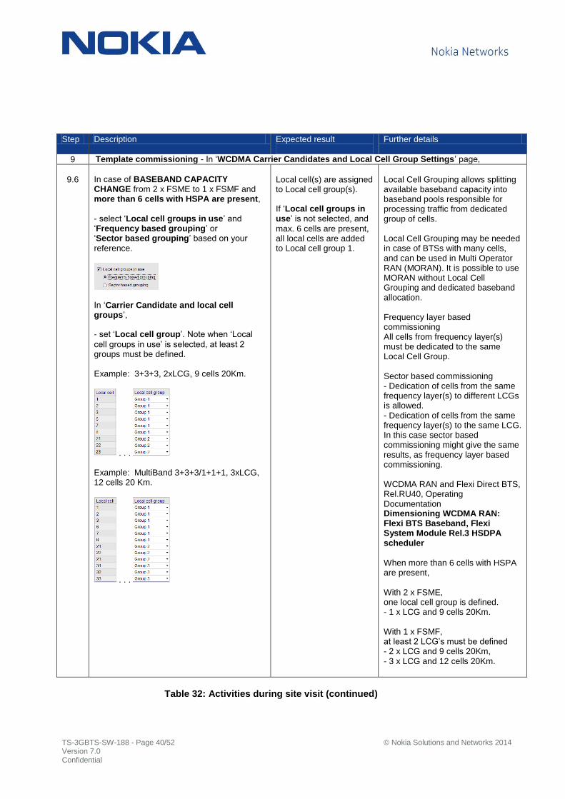
9.6
In case of BASEBAND CAPACITY CHANGE from 2 x FSME to 1 x FSMF and more than 6 cells with HSPA are present,
- select ‘Local cell groups in use’ and ‘Frequency based grouping’ or ‘Sector based grouping’ based on your
reference.
In ‘Carrier Candidate and local cell groups’,
- set ‘Local cell group’. Note when ‘Local
cell groups in use’ is selected, at least 2 groups must be defined. Example: 3+3+3, 2xLCG, 9 cells 20Km.
. . . Example: MultiBand 3+3+3/1+1+1, 3xLCG, 12 cells 20 Km.
. . .
Local cell(s) are assigned to Local cell group(s). If ‘Local cell groups in use’ is not selected, and
max. 6 cells are present, all local cells are added to Local cell group 1.
Local Cell Grouping allows splitting available baseband capacity into baseband pools responsible for processing traffic from dedicated group of cells. Local Cell Grouping may be needed in case of BTSs with many cells, and can be used in Multi Operator RAN (MORAN). It is possible to use MORAN without Local Cell Grouping and dedicated baseband allocation. Frequency layer based commissioning All cells from frequency layer(s) must be dedicated to the same Local Cell Group. Sector based commissioning - Dedication of cells from the same frequency layer(s) to different LCGs is allowed. - Dedication of cells from the same frequency layer(s) to the same LCG. In this case sector based commissioning might give the same results, as frequency layer based commissioning. WCDMA RAN and Flexi Direct BTS, Rel.RU40, Operating Documentation Dimensioning WCDMA RAN: Flexi BTS Baseband, Flexi System Module Rel.3 HSDPA scheduler
When more than 6 cells with HSPA are present, With 2 x FSME, one local cell group is defined. - 1 x LCG and 9 cells 20Km. With 1 x FSMF, at least 2 LCG’s must be defined - 2 x LCG and 9 cells 20Km, - 3 x LCG and 12 cells 20Km.
Table 32: Activities during site visit (continued)

TS-3GBTS-SW-188 - Page 41/52 © Nokia Solutions and Networks 2014 Version 7.0 Confidential
Step Description Expected result
Further details
9 Template commissioning - In ‘WCDMA Carrier Candidates and Local Cell Group Settings’ page
(continued),
9.6
In ‘Baseband (BB) and HSPA license allocations’,
- set BB and HSPA license allocation values according Local Cell Group preference. Example: 3+3+3, 1xLCG, 9 cells 20Km.
Example: MultiBand 3+3+3/1+1+1, 2xLCG, 12 cells 20 Km.
In ‘Mapping HSPA local cells to baseband HW and Parallel Interference Cancellation (PIC),
- set ‘PIC pools’ starting from lowest number
available and select ‘Next’ to continue. Example: 3+3+3, 1xLCG, 9 cells 20Km.
Example: MultiBand 3+3+3/1+1+1 3xLCG, 12 cells 20Km or 3+3+3+3, 3xLCG, 12 cells 20Km.
BB/HSPA license allocation and optional PIC pools are set. If ‘Local cell groups in use’ is not selected, BB
and HSPA license allocation and PIC pool setting is not available.
WCDMA RAN and Flexi Direct BTS, Rel.RU40, Operating Documentation Dimensioning WCDMA RAN: Flexi BTS Baseband, Flexi System Module Rel.3 HSDPA scheduler
When more than 6 cells with HSPA are present, for example 3+3+3 and Multi Band 3+3+3/1+1+1 configuration With 2 x FSME, one local cell group is defined. - 1 x LCG and 9 cells 20Km. With 1 x FSMF, at least 2 LCG’s must be defined - 2 x LCG and 9 cells 20Km, - 3 x LCG and 12 cells 20Km. The maximum available baseband capacity of FSMF for pure traffic depends on - Local Cell Group (LCG) - configuration type - Additional CCCH processing resources (if needed) - Number of activated Interference Cancellation units (PIC pools) - HSUPA static resources (optional static reservation for HSUPA data/voice users) - HS_Cell_FACH_UL static resources (optional static reservation for HS-FA CH UL users) RAN1308 HSUPA Interference Cancellation Receiver
If PIC Pool is not in use, on RNC side edit the ‘AdminPicState’ in to ‘Disabled’ under Admission Control tab.
Table 33: Activities during site visit (continued)

TS-3GBTS-SW-188 - Page 42/52 © Nokia Solutions and Networks 2014 Version 7.0 Confidential
Step Description Expected result
Further details
9 Template commissioning - In ‘HSDPA Settings’ page,
9.7
Include adequate amount of ‘HSDPA capacity sets’ in order to get throughput
allocated as per BTS Site preference.
- set ‘BTS processing set 1/2/3‘ according
BTS Site preferences.
HSDPA BTS processing set capacities:
HSDPA BTS processing set 1 - 32 users and 7.2Mbps HSDPA BTS processing set 2 - 72 users and 21Mbps HSDPA BTS processing set 3 - 72 users and 84Mbps.
In total, 1 x 21 + 2 x 84 Mbps = 189Mbps of licensed capacity available for all schedulers.
Scheduler licensed throughputs are calculated as per given formula (scheduler throughput steps from step 9.7) Scheduler 1 - LCG 1 = Round down {(1 + 4*2) * (12 /(12+6+6+3)) } * 21 Mbps = 84 Mbps
Scheduler 2 - LCG 1 = Round down {(1 + 4*2) * (6 /(12+6+6+3)) } * 21 Mbps = 42 Mbps
Scheduler 1 - LCG 2 = Round down {(1 + 4*2) * (6 /(12+6+6+3)) } * 21 Mbps = 42 Mbps
Scheduler 2 - LCG 2 = Round down {(1 + 4*2) * (3 /(12+6+6+3)) } * 21 Mbps = 21 Mbps
HSDPA processing set(s) are commissioned.
The HSDPA BTS processing set describes the maximum HSDPA capability that allows reaching a certain number of HSDPA users and DL throughput WCDMA RAN and Flexi Direct BTS, Rel.RU40, Operating Documentation Dimensioning WCDMA RAN: Flexi BTS Baseband, Flexi System Module Rel.3 HSDPA scheduler
Formula for scheduler licensed throughput:
If there are only HSDPA Processing Set 2 and three licenses are present in BTS, the division of licensed throughput will be done for each scheduler according to the formula below:
Scheduler_licensed_throughput = Round_down { (Number_of_HSDPA_Processing_Sets_2 + 4* Number_of_HSDPA_Processing_Sets_3) * (Scheduler_HSDPA_throughput_step / Total_number_of_HSDPA_throughput_step_per_BTS) } * 21 Mbps
If after calculations presented above throughput for all schedulers is lower than total licensed throughput in the BTS, the remaining throughput is distributed between activated schedulers.
Schedulers are prioritized in the following order:
a) Scheduler with lowest value of licensed throughput divided by commissioned throughput; b) Schedulers belonging to LCG with the lowest ID ( in case of Normal HSPA configuration (2 HSDPA schedulers activated) scheduler#1 is prioritized over scheduler#2).
Table 34: Activities during site visit (continued)

TS-3GBTS-SW-188 - Page 43/52 © Nokia Solutions and Networks 2014 Version 7.0 Confidential
Step Description Expected result
Further details
9 Template commissioning - In ‘HSDPA Throughput Settings’ page,
9.8
In ‘HSPA setting’,
- select HSPA configuration (HSPA setting)
option according LCG throughput requirements.
In ‘HSDPA throughput’,
- select a value according Local Cell Group requirements.
This setting is optional. If ‘Max throughput’ is left as ‘System default’, then 84Mbps is
allocated to every 1-6 non-MIMO cells.
In case BASEBAND CAPACITY CHANGE from 2 x FSME to1 x FSMF and more than 6 cells with HSPA are present,
- select ‘HSDPA throughput’ according
Local Cell Group preference. Each HSDPA throughput step corresponds to 7.2Mbps. Example: 3+3+3, 2xLCG, 9 cells 20Km.
Optional HSPA setting is selected and HSDPA throughput steps are selected.
There are three LCG configuration types available for FSMF which describes HSPA capability (number of HSPA supported cells and number of HSDPA/HSUPA schedulers). Rel.99 only configuration
Max number of supported cells = 12 Max number of HSPA cells = 6 Number of HSDPA schedulers = 0 Small HSPA configuration
Max number of supported cells = 6 Max number of HSPA cells = 6 Number of HSDPA schedulers = 1 Normal HSPA configuration
Max number of supported cells = 12 Max number of HSPA cells = 12 Number of HSDPA schedulers = 2 The LCG configuration type is set during B TS commissioning for each LCG separately using HSPA setting parameter. If not commissioned then ‘Normal HSPA’ configuration is assumed by default. WCDMA RAN and Flexi Direct BTS, Rel.RU40, Operating Documentation Dimensioning WCDMA RAN: Flexi BTS Baseband, Flexi System Module Rel.3 HSDPA scheduler
The scheduler provides HSDPA throughput, which depends on activated features, number and type of BTS processing sets, and HSDPA throughput commissioning by the operator. The HSDPA throughput step has No impact on HSDPA baseband capacity allocation but it is used for HSDPA licensed throughput distribution among available schedulers. In addition it can be used to limit HSDPA scheduler throughput
Table 35: Activities during site visit (continued)
TS-3GBTS-SW-188 - Page 44/52 © Nokia Solutions and Networks 2014 Version 7.0 Confidential
Step Description Expected result
Further details
9 Template commissioning - In ‘Antenna Line Settings’ page,
9.9
When RCUA+WMHC is used with FSMF, - allocate IP address for RCUA according to the principles described in the WCDMA RAN documentation. A public IP address/routing must be arranged also for the RealTilt Solution according to the same principles. - connect the device via external 10/100 Mbit switch/hub. RCUA works with 10 Mbit/s speed with no auto negotiation support. - see further details for performing RealTilt commissioning. Continue to navigate through the rest of the commissioning steps and before sending parameters, save commissioning file for reference / RF sharing to introduce WBTS commissioning to 2G BTS.
WCDMA RAN, Rel. RU40, Operating Documentation, Issue 04 Documentation Change Delivery 1 Commissioning Flexi Multiradio BTS WCDMA, Performing RealTilt Commissioning
If a firewall is installed on the PC, you may need to configure it to allow TCP ports 13062 – 13092 to accept incoming connections from the Flexi Multiradio BTS. This TCP port must be ‘open’ to enable Flexi BTS Site Manager commissioning file transfer to BTS. For further information about the specific firewall installed on your PC, contact your System Administrator or IT Helpdesk.
10 Update 2G BTS commissioning (optional)
10.1
RF SHARING (2G BTS)
- Establish 2G BTS Site manager connection, go into Commissioning Wizard and select ‘Change settings Manually’
option. - Navigate through commissioning steps until ‘HW Configuration’ page, select ‘Specify from File’ and pick previously saved
WCDMA BTS commissioning file (step 9.2). - Select ‘Do no change settings’ option in Transmission Parameter view in order to speed up re-commissioning step. - Select ‘Send SCF’ to activate new
commissioning file.
2G BTS Site manager connection can be established Prepared 3G SCF can be selected and commissioning process is started 2G BTS will perform a restart to activate new commissioning file.
Table 36: Activities during site visit (continued)
TS-3GBTS-SW-188 - Page 45/52 © Nokia Solutions and Networks 2014 Version 7.0 Confidential
Step Description Expected result
Further details
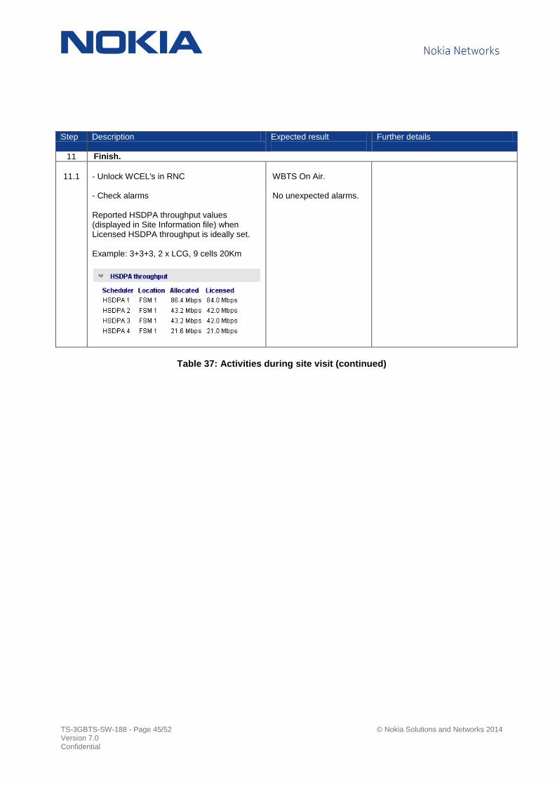
11 Finish.
11.1
- Unlock WCEL's in RNC - Check alarms Reported HSDPA throughput values (displayed in Site Information file) when Licensed HSDPA throughput is ideally set. Example: 3+3+3, 2 x LCG, 9 cells 20Km
WBTS On Air. No unexpected alarms.
Table 37: Activities during site visit (continued)

TS-3GBTS-SW-188 - Page 46/52 © Nokia Solutions and Networks 2014 Version 7.0 Confidential
7.5 Additional information
7.5.1 FSMF sub-modules
Product Code
Name Contents
472301A FPFD Power Distribution Sub –Module WCDMA RAN, Rel. RU40, Operating Documentation, Issue 03 Flexi Multiradio Base Station and Flexi Multiradio 10 Base Station Optional Items Description, Flexi Power Distribution Sub-Module (FPFD) description
472182A FBBA Capacity Extension Sub –Module WCDMA RAN, Rel. RU40, Operating Documentation, Issue 03 Cabling Flexi Multiradio 10 Base Station, Connecting Flexi Multiradio 10 BTS Capacity Extension Sub-Module (FBBA) cabling
472311A FTIF Transport Sub-module WCDMA RAN, Rel. RU40, Operating Documentation, Issue 03 RU40 Feature Descriptions and Instructions - 4.2 RAN2296: FTIF Eth+E1/T1/JT1 for Flexi Multiradio System Module
Table 38: FSMF sub-modules
7.5.2 FSMF synchronization cables
Product Code
Name Length (m)
Used for Note
472685A ESFB 12 ESMA/B/C -> FSMF Sync Cable ESMA/B/C to FSMF (MDR14 -> HDMI)
472576A FTSG 2 FSME/D -> FSMF Sync Cable G (MDR14 -> HDMI) 472799A FSCB 5 FSMF -> ESMA/B/C Sync Cable FSMF to ESMA/B/C (HDMI -> MDR26)
472808A FTSK 2 FSMF -> FSME/D Sync Cable FSMF to FSMD/E (HDMI -> MDR26) 472686A ESUB 12 FSMF -> Ultrasite EDGE Sync Cable FSMF to D15 Ultra (HDMI -> D15)
472846A FTSN 15 FSMF -> FSMF Sync Cable FSMF to FSMF (HDMI - HDMI) 472509A FTSF 2 FSMF -> FSMF Sync Cable F (HDMI - HDMI)
Table 39: FSMF synchronization cables
7.5.3 FSMF GPS feeding cables
Product Code
Name Length (m)
Used for Note
472510A FTSE 30 FSMF – GPS GPS cable assembly
472577A FTSH 100 FSMF – GPS GPS cable assembly
Table 40: GPS feeding cables

TS-3GBTS-SW-188 - Page 47/52 © Nokia Solutions and Networks 2014 Version 7.0 Confidential
7.5.4 FSMF EAC cables
Product Code
Name Length (m)
Used for Note
472839A FSAH 15 FSMF – FSEB (471424A) EAC cable (HDMI-D37)
472693A FSAE 2 FSMF – units with RJ45 EAC cable (HDMI-RJ45)
472578A FTSI 2,5 FSMF – FSEB (471424A) EAC cable (HDMI-D37)
Table 41: FSMF EAC cables
7.5.5 FSMF EAC signal and pin assignment
Pin Signal Function
1 EXT_AL0_H External Alarm 0
2 EXT_AL1_H External Alarm 1
3 EXT_AL2_H External Alarm 2
4 EXT_AL3_H External Alarm 3
5 EXT_AL4_H External Alarm 4
6 EXT_AL5_H External Alarm 5
7 EXT_CTRL0_EXT_AL6_H Shared Control line 0 / Alarm 6
8 EXT_CTRL1_EXT_AL7_H Shared Control line 1 / Alarm 7
9 EXT_CTRL2_EXT_AL8_H Shared Control line 2 / Alarm 8
10 EXT_CTRL3_EXT_AL9_H Shared Control line 3 / Alarm 9
11 EXT_CTRL4_EXT_AL10_H Shared Control line 4 / Alarm 10
12 EXT_CTRL5_EXT_AL11_H Shared Control line 5 / Alarm 11
13 GND Ground
14 GND Ground
15 PROT_CAN_H_P5V_EAC CAN serial line positive
16 GND Ground
17 PROT_CAN_L_P5V_EAC CAN serial line negative
18 P5V_EAC CAN 5V Supply or Supply for Controls
19 GND Ground
Table 42: FSMF EAC interface signals and pin assignment
TS-3GBTS-SW-188 - Page 48/52 © Nokia Solutions and Networks 2014 Version 7.0 Confidential
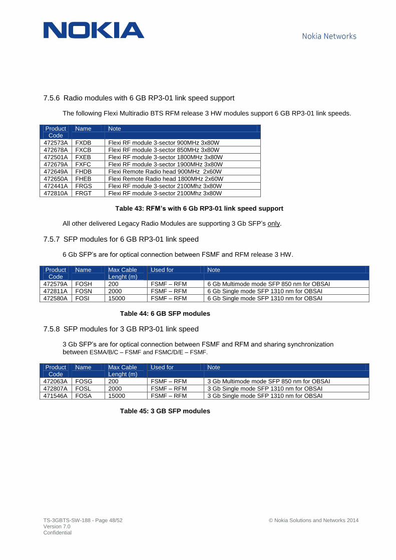
7.5.6 Radio modules with 6 GB RP3-01 link speed support
The following Flexi Multiradio BTS RFM release 3 HW modules support 6 GB RP3-01 link speeds.
Product Code
Name Note
472573A FXDB Flexi RF module 3-sector 900MHz 3x80W
472678A FXCB Flexi RF module 3-sector 850MHz 3x80W
472501A FXEB Flexi RF module 3-sector 1800MHz 3x80W
472679A FXFC Flexi RF module 3-sector 1900MHz 3x80W
472649A FHDB Flexi Remote Radio head 900MHz 2x60W
472650A FHEB Flexi Remote Radio head 1800MHz 2x60W
472441A FRGS Flexi RF module 3-sector 2100Mhz 3x80W
472810A FRGT Flexi RF module 3-sector 2100Mhz 3x80W
Table 43: RFM’s with 6 Gb RP3-01 link speed support
All other delivered Legacy Radio Modules are supporting 3 Gb SFP’s only.
7.5.7 SFP modules for 6 GB RP3-01 link speed
6 Gb SFP’s are for optical connection between FSMF and RFM release 3 HW.
Product Code
Name Max Cable Lenght (m)
Used for Note
472579A FOSH 200 FSMF – RFM 6 Gb Multimode mode SFP 850 nm for OBSAI
472811A FOSN 2000 FSMF – RFM 6 Gb Single mode SFP 1310 nm for OBSAI
472580A FOSI 15000 FSMF – RFM 6 Gb Single mode SFP 1310 nm for OBSAI
Table 44: 6 GB SFP modules
7.5.8 SFP modules for 3 GB RP3-01 link speed
3 Gb SFP’s are for optical connection between FSMF and RFM and sharing synchronization between ESMA/B/C – FSMF and FSMC/D/E – FSMF.
Product Code
Name Max Cable Lenght (m)
Used for Note
472063A FOSG 200 FSMF – RFM 3 Gb Multimode mode SFP 850 nm for OBSAI
472807A FOSL 2000 FSMF – RFM 3 Gb Single mode SFP 1310 nm for OBSAI
471546A FOSA 15000 FSMF – RFM 3 Gb Single mode SFP 1310 nm for OBSAI
Table 45: 3 GB SFP modules
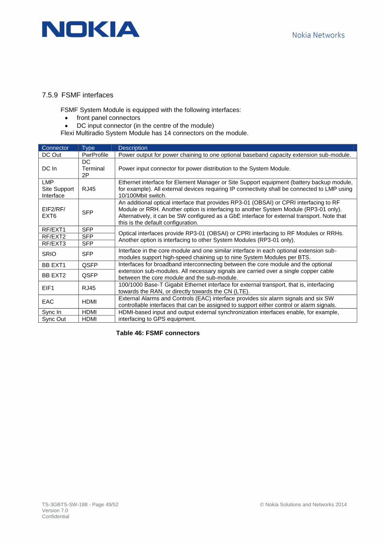
TS-3GBTS-SW-188 - Page 49/52 © Nokia Solutions and Networks 2014 Version 7.0 Confidential
7.5.9 FSMF interfaces
FSMF System Module is equipped with the following interfaces:
front panel connectors
DC input connector (in the centre of the module) Flexi Multiradio System Module has 14 connectors on the module.
Connector Type Description
DC Out PwrProfile Power output for power chaining to one optional baseband capacity extension sub-module.
DC In DC Terminal 2P
Power input connector for power distribution to the System Module.
LMP Site Support Interface
RJ45 Ethernet interface for Element Manager or Site Support equipment (battery backup module, for example). All external devices requiring IP connectivity shall be connected to LMP using 10/100Mbit switch.
EIF2/RF/ EXT6
SFP
An additional optical interface that provides RP3-01 (OBSAI) or CPRI interfacing to RF Module or RRH. Another option is interfacing to another System Module (RP3-01 only). Alternatively, it can be SW configured as a GbE interface for external transport. Note that this is the default configuration.
RF/EXT1 SFP Optical interfaces provide RP3-01 (OBSAI) or CPRI interfacing to RF Modules or RRHs. Another option is interfacing to other System Modules (RP3-01 only).
RF/EXT2 SFP
RF/EXT3 SFP
SRIO SFP Interface in the core module and one similar interface in each optional extension sub-modules support high-speed chaining up to nine System Modules per BTS.
BB EXT1 QSFP Interfaces for broadband interconnecting between the core module and the optional extension sub-modules. All necessary signals are carried over a single copper cable between the core module and the sub-module. BB EXT2 QSFP
EIF1 RJ45 100/1000 Base-T Gigabit Ethernet interface for external transport, that is, interfacing towards the RAN, or directly towards the CN (LTE).
EAC HDMI External Alarms and Controls (EAC) interface provides six alarm signals and six SW controllable interfaces that can be assigned to support either control or alarm signals.
Sync In HDMI HDMI-based input and output external synchronization interfaces enable, for example, interfacing to GPS equipment. Sync Out HDMI
Table 46: FSMF connectors

TS-3GBTS-SW-188 - Page 50/52 © Nokia Solutions and Networks 2014 Version 7.0 Confidential
Figure 4: FSMF System Module front panel
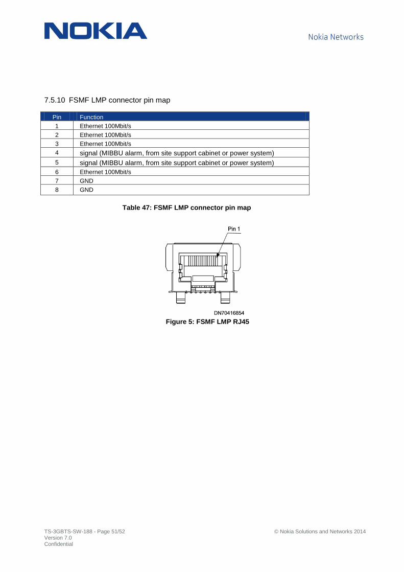
TS-3GBTS-SW-188 - Page 51/52 © Nokia Solutions and Networks 2014 Version 7.0 Confidential
7.5.10 FSMF LMP connector pin map
Pin Function
1 Ethernet 100Mbit/s
2 Ethernet 100Mbit/s
3 Ethernet 100Mbit/s
4 signal (MIBBU alarm, from site support cabinet or power system)
5 signal (MIBBU alarm, from site support cabinet or power system)
6 Ethernet 100Mbit/s
7 GND
8 GND
Table 47: FSMF LMP connector pin map
Figure 5: FSMF LMP RJ45
TS-3GBTS-SW-188 - Page 52/52 © Nokia Solutions and Networks 2014 Version 7.0 Confidential
Disclaimer
The information in this document applies solely to the hardware/software product (“Product”) specified herein, and only as specified herein.
This document is intended for use by Nokia Solutions and Networks' customers (“You”) only, and it may not be used except for the purposes defined in the agreement between You and Nokia Solutions and Networks (“Agreement”) under which this document is distributed. No part of this document may be used, copied, reproduced, modified or transmitted in any form or means without the prior written permission of Nokia Solutions and Networks. If you have not entered into an Agreement applicable to the Product, or if that Agreement has expired or has been terminated, You may not use this document in any manner and You are obliged to return it to Nokia Solutions and Networks and destroy or delete any copies thereof.
The document has been prepared to be used by professional and properly trained personnel, and You assume full responsibility when using it. Nokia Solutions and Networks welcome Your comments as part of the process of continuous development and improvement of the documentation.
This document and its contents are provided as a convenience to You. Any information or statements concerning the suitability, capacity, fitness for purpose or performance of the Product are given solely on an “as is” and “as available” basis in this document, and Nokia Solutions and Networks reserves the right to change any such information and statements without notice. Nokia Solutions and Networks has made all reasonable efforts to ensure that the content of this document is adequate and free of material errors and omissions, and Nokia Solutions and Networks will correct errors that You identify in this document. But, Nokia Solutions and Networks' total liability for any errors in the document is strictly limited to the correction of such error(s). Nokia Solutions and Networks does not warrant that the use of the software in the Product will be uninterrupted or error-free.
NO WARRANTY OF ANY KIND, EITHER EXPRESS OR IMPLIED, INCLUDING BUT NOT LIMITED TO ANY WARRANTY OF AVAILABILITY, ACCURACY, RELIABILITY, TITLE, NON-INFRINGEMENT, MERCHANTABILITY OR FITNESS FOR A PARTICULAR PURPOSE, IS MADE IN RELATION TO THE CONTENT OF THIS DOCUMENT. IN NO EVENT WILL NOKIA SOLUTIONS AND NETWORKS BE LIABLE FOR ANY DAMAGES, INCLUDING BUT NOT LIMITED TO SPECIAL, DIRECT, INDIRECT, INCIDENTAL OR CONSEQUENTIAL OR ANY LOSSES, SUCH AS BUT NOT LIMITED TO LOSS OF PROFIT, REVENUE, BUSINESS INTERRUPTION, BUSINESS OPPORTUNITY OR DATA THAT MAY ARISE FROM THE USE OF THIS DOCUMENT OR THE INFORMATION IN IT, EVEN IN THE CASE OF ERRORS IN OR OMISSIONS FROM THIS DOCUMENT OR ITS CONTENT.
This document is Nokia Solutions and Networks’ proprietary and confidential information, which may not be distributed or disclosed to any third parties without the prior written consent of Nokia Solutions and Networks.
Nokia is a registered trademark of Nokia Corporation. Other product names mentioned in this document may be trademarks of their respective owners, and they are mentioned for identification purposes only.
Copyright © 2014 Nokia Solutions and Networks. All rights reserved.