fsos getting started operation
TRANSCRIPT

Getting Started Operation
FSOS
Getting Started Operation

Getting Started Operation
Contents
1. Logging in Ethernet Switch................................................................................................1
1.1 Set up Configuration Environment via Console Port.............................................1
1.2 Set up Configuration Environment through Telnet.................................................2
1.2.1 Connect PC to Ethernet Switch through Telnet.......................................... 2
1.2.2 Telnet Ethernet Switch through Ethernet Switch.........................................4
2. Command Line Interface.....................................................................................................5
2.1 Introduction of Command Line Interface................................................................ 5
2.2 Command Line Configuration Mode.........................................................................5
2.3 Feature and Functions of Command Line...............................................................7
2.3.1 Help of Command Line...................................................................................7
2.3.2 Displaying Characteristics of Command Line................................................8
2.3.3 Show history Command of Command Line................................................. 9
2.3.4 Common Command Line Error Messages.....................................................9
2.4 Symbols in Command.............................................................................................. 10
2.5 Parameter in command........................................................................................... 10
3. Manage Users.....................................................................................................................11
3.1 System Default User.................................................................................................11
3.2 User’s Authentication............................................................................................... 12
3.3 Local Authentication Configuration......................................................................... 12
3.3.1 Add Users....................................................................................................... 12
3.3.2 Change Password............................................................................................12
3.3.3 Modify User's Privilege Level....................................................................... 13
3.3.4 Delete User.....................................................................................................13
3.3.5 Show Users.....................................................................................................14
3.4 Remote Authentication Configuration.....................................................................14
3.4.1 Configure RADIUS to Be Remote Authentication Server..........................14
3.4.2 Configure TACACS+ Remote Authentication................................................15

Getting Started Operation
1
1. Logging in Ethernet Switch
This chapter describes how to connect to the switch and do the configurations. There areways as via console port and through telnet. It contains following sections: Set up Configuration Environment via the Console Port
Set up Configuration Environment through Telnet
Telnet Ethernet Switch through Ethernet Switch
1.1 Set up Configuration Environment via Console Port
Step 1: As shown in the figure below, to set up the local configuration environment, connectthe serial port of a PC (or a terminal) to the Console port of the Ethernet switch with theConsole cable.
Console port
RS-232 Serial port
Console cable
Figure 1-1 Set up the local configuration environment via the Console port
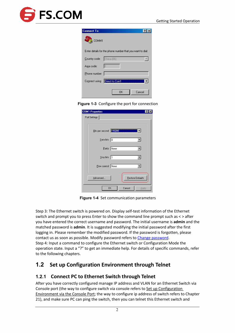
Step 2: Run terminal emulator (such as Hyper Terminal on Windows 9X/2000/XP/Vista) onthe Computer. Set the terminal communication parameters as follows: Set the baud rate to115200, data bit to 8, parity check to none, stop bit to 1, flow control to none and select theterminal type as auto-detection.
Figure 1-2 Set up new connection
Getting Started Operation
2
Figure 1-3 Configure the port for connection
Figure 1-4 Set communication parameters
Step 3: The Ethernet switch is powered on. Display self-test information of the Ethernetswitch and prompt you to press Enter to show the command line prompt such as < > afteryou have entered the correct username and password. The initial username is admin and thematched password is admin. It is suggested modifying the initial password after the firstlogging in. Please remember the modified password. If the password is forgotten, pleasecontact us as soon as possible. Modify password refers to Change password.Step 4: Input a command to configure the Ethernet switch or Configuration Mode theoperation state. Input a “?” to get an immediate help. For details of specific commands, referto the following chapters.
1.2 Set up Configuration Environment through Telnet
1.2.1 Connect PC to Ethernet Switch through TelnetAfter you have correctly configured manage IP address and VLAN for an Ethernet Switch viaConsole port (the way to configure switch via console refers to Set up ConfigurationEnvironment via the Console Port; the way to configure ip address of switch refers to Chapter21), and make sure PC can ping the switch, then you can telnet this Ethernet switch and

Getting Started Operation
3
configure it.
Step 1: Authenticate the Telnet user via the Console port before the user logs in by Telnet.Step 2: To set up the configuration environment, connect the Ethernet portof the PC to that of the Ethernet switch via the LAN.
Workstation
WorkstationServ er PC ( for configuring the switchvia Telnet )
Ethernet portEthernet
Workstation
WorkstationServ er PC ( for configuring the switchvia Telnet )
Ethernet portEthernet
Figure 1-1 Set up configuration environment through telnet
Step 3: Run Telnet on the PC and input the IP address of the VLAN connected to the PC port.
Figure 1-2 Run Telnet
Step 4: The terminal displays “Username (1-32 chars):” and prompts the userto input the login username and password. After you input the correct username andcorresponded password, it displays the command line prompt (such as < >). If the prompt“Too many users!” appears, it indicates that too many users are connected to the Ethernetthrough the Telnet at this moment. In this case, please reconnect later. At most 5 Telnetusers are allowed to log in to the series Ethernet Switches simultaneously. Default usernameis admin and the password is admin. If the default password has been modified, it requiresthe modified password.Step 5: Use the corresponding commands to configure the Ethernet switch or to monitor therunning state. Enter “?” to get the immediate help. For details of specific commands, refer tothe following chapters.
Note:When configuring the Ethernet switch via Telnet, do not modify the IP addressof it unnecessary, for the modification might cut the Telnet connection.

Getting Started Operation
4
1.2.2 Telnet Ethernet Switch through Ethernet SwitchThe switch can be both the Telnet server and client. After a user has telnet to a switch fromPC, he or she can configure another switch through this switch via Telnet. The local switchserves as Telnet client and the peer switch serves as Telnet server. If the ports connectingthese two switches are in a same local network, their IP addresses must be configured in thesame network segment. Otherwise, the two switches must establish a route that can reacheach other.As shown in the figure below, after you telnet to an Ethernet switch (that is Telnet Client inFigure 2-1), you can run telnet command to log in and configure another Ethernet switch(that is Telnet Server in Figure2-1).
Telnet ClientPC Telnet Server
Figure 1-1 Provide Telnet Client service
Step 1: Configure IP address for the switch (that is Telnet Client in Figure 2-1). The way toconfigure switch via console refers to Set up Configuration Environment via the Console Port;the way to configure ip address of switch refers to Chapter 21).Step 2: The user logs in the Telnet Client (Ethernet switch). For the login process, refer to thesection describing “Telnet PC to Ethernet Switch”.Step 3: Perform the following operations on the Telnet Client:
#telnet A.B.C.D (A.B.C.D is the IP address of the Telnet Server.)
Step 4: Enter the preset login password and you will see the prompt such < >. If the prompt“Too many users!” appears, it indicates that too many users are connected to the Ethernetthrough the Telnet at this moment. In this case, please connect later.Step 5: Use the corresponding commands to configure the Ethernet switch or ConfigurationMode it running state. Enter “?” to get the immediate help. For details of specific commands,refer to the following chapters.

Getting Started Operation
5
2. Command Line Interface
This chapter describes command line interface (CLI) which you may use to configure yourswitch. It contains flowing sections: Introduction of CLI
CLI mode
Feature and functions of CLI
Symbols in command
Parameters in command
2.1 Introduction of Command Line Interface
Ethernet Switches provide a series of configuration commands and command line interfacesfor configuring and managing the Ethernet switch. The command line interface has thefollowing characteristics: Local configuration via the Console port. Local or remote configuration via Telnet. Hierarchy command protection to avoid the unauthorized users accessing Ethernetswitch. Enter a “?” to get immediate online help. Provide network testing commands, such as Tracert and Ping, to fast troubleshoot thenetwork. Provide various detailed debugging information to help with network troubleshooting. Log in and manage other Ethernet switch directly, using the Telnet command. Provide FTP/TFTP/Xmodem service for the users to upload and download files.The command line interpreter searches for target not fully matching the keywords. It is ok foryou to key in the whole keyword or part of it, as long as it is unique and not ambiguous.
2.2 Command Line Configuration Mode
Ethernet Switches provide hierarchy protection for the command lines to avoid unauthorizeduser accessing illegally.Commands are classified into three levels, namely visit and monitoring level, configurationlevel and management level. They are introduced as follows: Visit and monitoring level: Commands of this level involve command of networkdiagnosis tool (such as ping and tracert), command of switch between different languageenvironments of user interface (language-mode) and telnet command etc and including thedisplay command and the debugging command, are used to systemmaintenance, servicefault diagnosis, etc. The operation of saving configuration file is not allowed on this level ofcommands. Configuration level: Service configuration commands, including routing command andcommands on each network layer are used to provide direct network service to the user. Management level: They are commands that influence basis operation of the systemand system support module, which plays a support role on service. Commands of this levelinvolve file system commands, FTP commands, TFTP commands, Xmodem downloadingcommands, user management commands, and level setting commands.At the same time, login users are classified into three levels that correspond to the three

Getting Started Operation
6
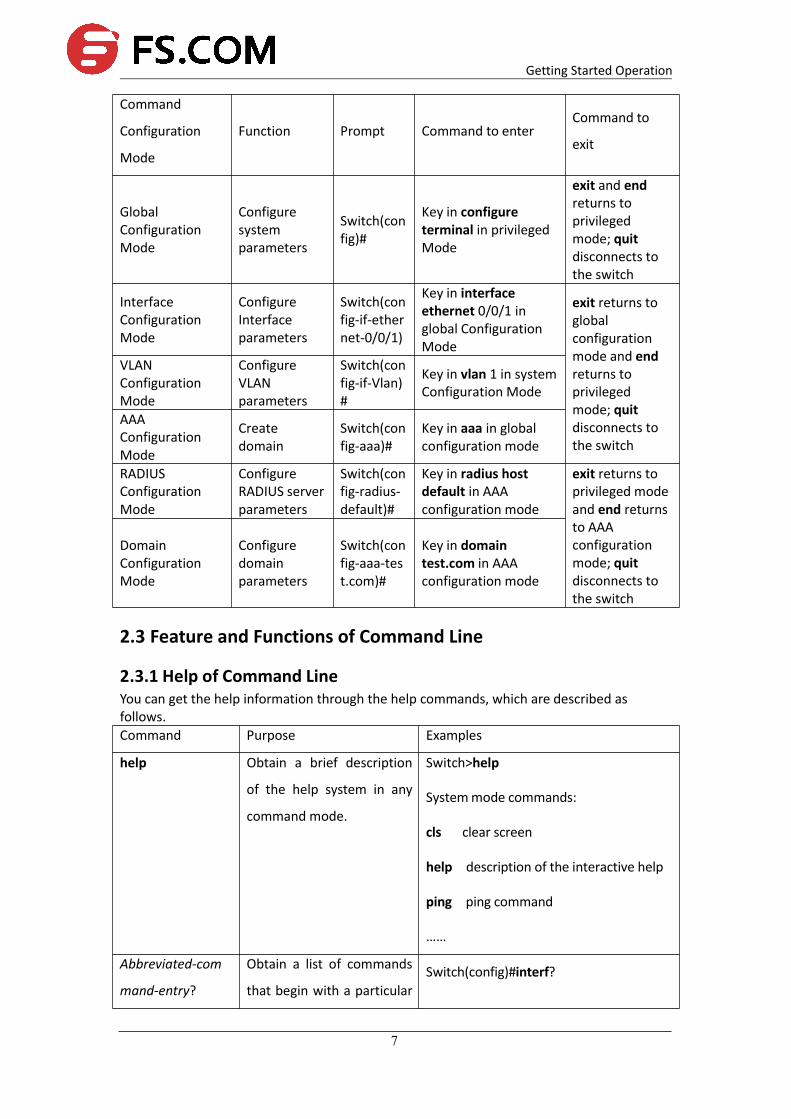
command levels respectively. After users of different levels logging in, they can only usecommands at the levels that are equal to or lower than their own level.In order to prevent unauthorized users from illegal intrusion, user will be identified whenswitching from a lower level to a higher level with username username [privilege level]{password encryption-type password} command. For the sake of confidentiality, on thescreen the user cannot see the password that he entered. Only when correct password isinput for three times, can the user switch to the higher level. Otherwise, the original userlevel will remain unchanged.Different command configuration mode is implemented according to different requirements.They are related to one another. For example, after logging in the Ethernet switch, you willenter user mode, in which you can only use some basic functions such as displaying therunning state and statistics information. In user mode, key in enable to enter privilegedmode, in which you can key in different configuration commands and enter thecorresponding configuration modes.The command line provides the following configuration modes: User Mode Privileged Mode Global Configuration Mode Interface Configuration Mode VLAN Configuration Mode AAA Configuration Mode RADIUS Configuration Mode Domain Configuration ModeThe following table describes the function features of different Configuration Modes and theways to enter or quit.
Table 1-1 Function feature of Command Configuration Mode
Command
Configuration
Mode
Function Prompt Command to enterCommand to
exit
User Mode
Show thebasicinformationaboutoperation andstatistics
Switch> Enter right afterconnecting the switch
exit disconnectsto the switch
Privileged mode
Show thebasicinformationaboutoperation andstatistics andmanage thesystem
Switch# Key in enable in usermode
exit returns touser mode; quitdisconnects tothe switch
Getting Started Operation
7
Command
Configuration
Mode
Function Prompt Command to enterCommand to
exit
GlobalConfigurationMode
Configuresystemparameters
Switch(config)#
Key in configureterminal in privilegedMode
exit and endreturns toprivilegedmode; quitdisconnects tothe switch
InterfaceConfigurationMode
ConfigureInterfaceparameters
Switch(config-if-ethernet-0/0/1)
Key in interfaceethernet 0/0/1 inglobal ConfigurationMode
exit returns toglobalconfigurationmode and endreturns toprivilegedmode; quitdisconnects tothe switch
VLANConfigurationMode
ConfigureVLANparameters
Switch(config-if-Vlan)#
Key in vlan 1 in systemConfiguration Mode
AAAConfigurationMode
Createdomain
Switch(config-aaa)#
Key in aaa in globalconfiguration mode
RADIUSConfigurationMode
ConfigureRADIUS serverparameters
Switch(config-radius-default)#
Key in radius hostdefault in AAAconfiguration mode
exit returns toprivileged modeand end returnsto AAAconfigurationmode; quitdisconnects tothe switch
DomainConfigurationMode
Configuredomainparameters
Switch(config-aaa-test.com)#
Key in domaintest.com in AAAconfiguration mode
2.3 Feature and Functions of Command Line
2.3.1 Help of Command LineYou can get the help information through the help commands, which are described asfollows.Command Purpose Examples
help Obtain a brief description
of the help system in any
command mode.
Switch>help
Systemmode commands:
cls clear screen
help description of the interactive help
ping ping command
……
Abbreviated-com
mand-entry?
Obtain a list of commands
that begin with a particularSwitch(config)#interf?

Getting Started Operation
8
character string. interface
? List all commands available
for a particular command
mode.
Switch>?
Systemmode commands:
cls clear screen
help description of the interactive help
ping ping command
……
command? List the associated
keywords for a command.Switch(config)#spanning-tree ?
forward-time config switch delaytime
hello-time config switch hellotime
max-age config switch max
agingtime
priority config switch priority
<enter> The command end.
command
keyword?
List the associated
arguments for a keyword.
Switch(config)#spanning-tree
forward-time ?
INTEGER<4-30> switch delaytime:
<4-30>(second)
Note:
To switch to the Chinese display for the above information, perform the terminallanguage {chinese | english} command in privileged mode.
2.3.2 Displaying Characteristics of Command LineCommand line interface provides the following display characteristics:For users’ convenience, the instruction and help information can be displayed in both Englishand Chinese.For the information to be displayed exceeding one screen, pausing function is provided. Inthis case, users can have three choices, as shown in the table below.
Table 1-2 Functions of displaying

Getting Started Operation
9
Key or Command Function
Press <Ctrl+C> when the display pauses Stop displaying and executing command.
Press other key when the display pauses Continue to display the next screen ofinformation.
Press <Enter> when the display pauses Continue to display the next line ofinformation.
2.3.3 Show history Command of Command LineCommand line interface provides the function similar to that of DosKey. The commandsentered by users can be automatically saved by the command line interface and you caninvoke and execute them at any time later. History command buffer is defaulted as 100. Thatis, the command line interface can store 100 history commands for each user. The operationsare shown in the table below.
Table 1-3 Retrieve history command
Operation Key Result
Retrieve the previoushistory command
Up cursor key <↑> or<Ctrl+P>
Retrieve the previous historycommand, if there is any.
Retrieve the next historycommand
Down cursor key <↓>or <Ctrl+N>
Retrieve the next historycommand, if there is any.
Note:Cursor keys can be used to retrieve the history commands in Windows9X/2000/XP Terminal and Telnet.
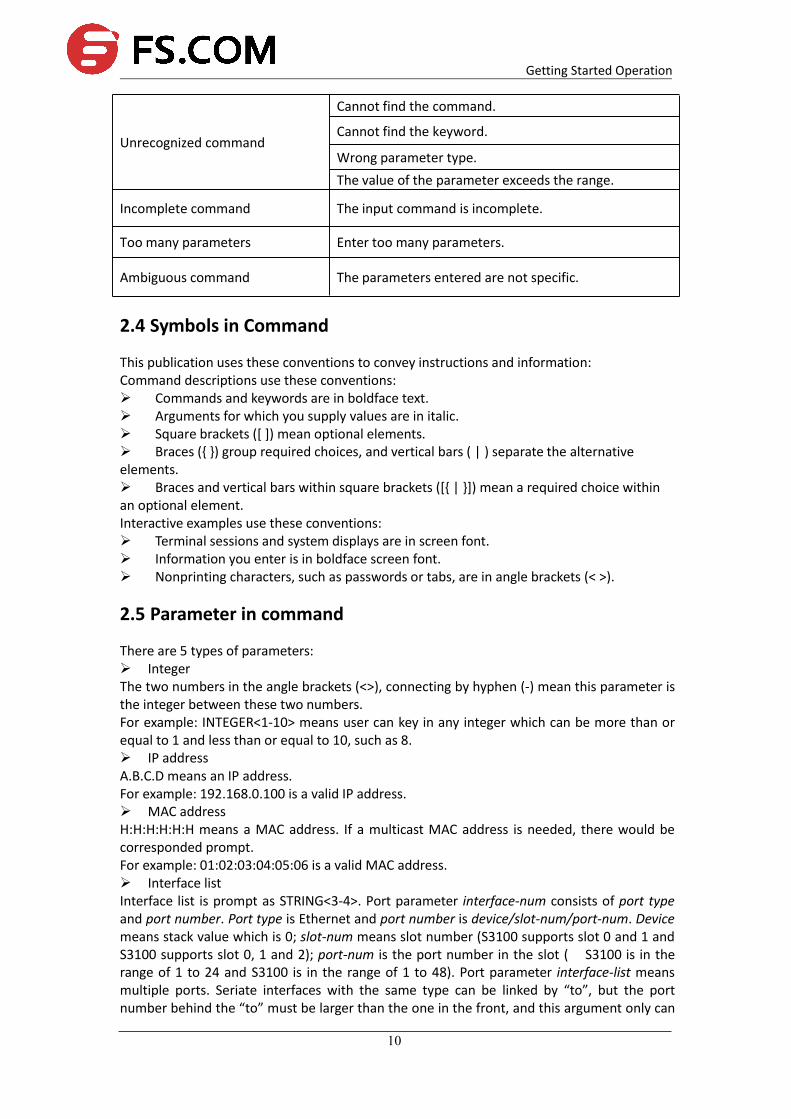
2.3.4 Common Command Line Error MessagesAll the input commands by users can be correctly executed, if they have passed the grammarcheck. Otherwise, error messages will be reported to users. The common error messages arelisted in the following table.
Table 1-4 Common command line error messages
Error messages Causes
Getting Started Operation
10
Unrecognized command
Cannot find the command.
Cannot find the keyword.
Wrong parameter type.The value of the parameter exceeds the range.
Incomplete command The input command is incomplete.
Too many parameters Enter too many parameters.
Ambiguous command The parameters entered are not specific.
2.4 Symbols in Command
This publication uses these conventions to convey instructions and information:Command descriptions use these conventions: Commands and keywords are in boldface text. Arguments for which you supply values are in italic. Square brackets ([ ]) mean optional elements. Braces ({ }) group required choices, and vertical bars ( | ) separate the alternativeelements. Braces and vertical bars within square brackets ([{ | }]) mean a required choice withinan optional element.Interactive examples use these conventions: Terminal sessions and system displays are in screen font. Information you enter is in boldface screen font. Nonprinting characters, such as passwords or tabs, are in angle brackets (< >).
2.5 Parameter in command
There are 5 types of parameters: IntegerThe two numbers in the angle brackets (<>), connecting by hyphen (-) mean this parameter isthe integer between these two numbers.For example: INTEGER<1-10> means user can key in any integer which can be more than orequal to 1 and less than or equal to 10, such as 8. IP addressA.B.C.D means an IP address.For example: 192.168.0.100 is a valid IP address. MAC addressH:H:H:H:H:H means a MAC address. If a multicast MAC address is needed, there would becorresponded prompt.For example: 01:02:03:04:05:06 is a valid MAC address. Interface listInterface list is prompt as STRING<3-4>. Port parameter interface-num consists of port typeand port number. Port type is Ethernet and port number is device/slot-num/port-num. Devicemeans stack value which is 0; slot-num means slot number (S3100 supports slot 0 and 1 andS3100 supports slot 0, 1 and 2); port-num is the port number in the slot ( S3100 is in therange of 1 to 24 and S3100 is in the range of 1 to 48). Port parameter interface-list meansmultiple ports. Seriate interfaces with the same type can be linked by “to”, but the portnumber behind the “to” must be larger than the one in the front, and this argument only can

Getting Started Operation
11
be repeated up to 3 times. The special declaration of interface parameter interface list willbe displayed in the command.For example: Showing spanning-tree interface ethernet 0/0/1 ethernet 0/0/3 to ethernet0/0/5 means showing the spanning-tree information about interface ethernet 0/0/1,ethernet 0/0/2, ethernet 0/0/3, ethernet 0/0/4 and ethernet 0/0/5. StringThe prompt STRING<1-19> means a character string which is in the length of1 to 19. Enter“?” to see the parameter description of this command.
3. Manage Users
There are three kinds of users: Super-administrator Administrator Normal userThe normal users can only be in the user's mode after logging in the switch so they can onlycheck the basic information about operation and statistics; administrator can enter eachconfiguration mode to check and manage the system; super-administrator can both managethe system and all kinds of users.
Note:Normal users cannot configure the switch and change their own password.Administrator can manage himself; for example, change his own privilege andpassword. It cannot create or delete other users and change other user’spassword and privilege.
This chapter contains following sections: System default user Add users Change password Modify User's Privilege Level Delete User Show users
3.1 System Default User
There is an internal username with password called Super-administrator. It processes thesuperior priority in the switch to manage both the users and the switch.The username of Super-administrator is admin and its initial password is admin. It issuggested modifying the password after the initial-logging in. This username and itsadministrator privilege cannot be deleted and modified.
Note:There must be only one super-administrator and all the configurations in themanual is setting super-administrator as example.

Getting Started Operation
12
3.2 User’s Authentication
User’s authentication can be divided into local authentication and remote authentication: Local authentication:The users’ account and password are saved in local database. Allusers are supported by local authentication. Remote authentication:The users’ account and password are saved in RADIUS/TACACS+server. Super-administrator “admin” is not supported by remote authentication.
3.3 Local Authentication Configuration
3.3.1 Add UsersAt most 15 users can be added. Log in the switch first as Super-administrator and create newusers as following steps:
Table 1-5 Add users
Step Command Description
1 enable Enter privileged mode
2 config terminal Enter global configuration mode
3 username username privilege
privilege <0,1> password password
Adding a new user and specified the
privilege.
4 show username Check the configuration.
5 exit Exit to user mode
6 copy running-config startup-config Save the configuration
Note:Username: it means the name of the user to be added which must be 1 to 32printable characters without '/',':','*','?','\\','<','>','|','"'.Level: means the priority of the user to be added which is the number between0 and 15. 0 and 1 mean the normal user and 2 to 15 mean the administrator.encryption-type: it can be 0 or 7. 0 means clear text and 7 means encrypted text(not supported now).privilege it can be 0, 1 or 2 to 15. 0 and 1 mean normal users while 2 to 15 meanadministrators.Password: the login password of new-added user which is 1 to 16 characters.If the user's privilege level is not specified, it will default to be normal user.There is up to 8 users in the system.
Caution: Case-sensitive is for password but not username.
Example:!Create administrator "XXXX" with its password being 1234 and privilege level is 3Switch(config)#username XXXX privilege 3 password 0 1234
3.3.2 Change PasswordIn global configuration mode, Super-administrator "admin" can use following command tochange the password of all users, but other administrators can only change their ownpassword. Normal users cannot modify their own password.

Getting Started Operation
13
Enter global configuration mode (how to enter global configuration mode refers to the first 2steps in Table 4-1) before following the below steps:
Table 4-2 Modify password
Step Command Description
1 username change-password Enter the modified password following the
prompt. The new password will be
effective in the next log in.
2 exit Exit to user mode
3 copy running-config startup-config Save the configurationExample:!Change the password of user "XXXX" to be adminSwitch(config)#username change-passwordplease input you login password : ******please input username :XXXXPlease input user new password :******Please input user comfirm password :******change user XXXX password success.
3.3.3 Modify User's Privilege LevelIn global configuration mode, only Super-administrator "admin" can modify the privilegelevel of other users. Enter global configuration mode (how to enter global configurationmode refers to the first 2 steps in Table 4-1) before following the below steps:
Table 4-3 Modify User's Privilege Level
Step Command Description
1 username username privilege privilege<0-15> Modify user’s privilege.
2 show username Check configuration.
3 exit Exit to user mode
4 copy running-config startup-config Save the configuration
Note:
Username: means the name of the existed user to be modified which must be 1to 32 printable characters without '/',':','*','?','\\','<','>','|','"'. If the enteredusername is not existed, add it to be the new one.Level: means the priority of the existed user (except the Super-administrator) tobe modified which is the number between 0 and 15. 0 and 1 mean the normaluser and 2 to 15 mean the administrator.
Caution: Case-sensitive is for password but not username.
Example:!Modify the privilege of the existed user "XXXX" to be 1 and its password to be 1234Switch(config)#username XXXX privilege 0 password 0 1234
3.3.4 Delete UserOnly Super-administrator "admin" can add and delete user in global configuration mode.

Getting Started Operation
14
Enter global configuration mode (how to enter global configuration mode refers to the first 2steps in Table 4-1) before following the below steps:
Table 4-4 Delete user
Step Command Description
1 no username username Delete user.
2 show username Check configuration.
3 exit Exit to user mode
4 copy running-config startup-config Save the configuration
Note:Username: means the name of the user to be deleted.When deleting a user which is used, it will be disconnected before delete it.
Example:!Delete user "XXXX"Switch(config)#no username XXXX
3.3.5 Show UsersAfter configuration, you can use following steps to check it. Any configurationmode ispermitted.
Table 4-5 Show users
Step Command Description
1 show username Show specific user.
2 show users Show users’ log. At most 5
users are permitted on line
at the same time.
3.4 Remote Authentication Configuration
3.4.1 Configure RADIUS to Be Remote Authentication ServerTable 4-6 configure RADIUS remote authentication
Operation Command Description
Enter global configuration configure terminal -
Enable RADIUS remote
authentication
muser radius name {chap|pap}
[local]
Selected
If “local” is configured,
it means local
authentication is used if
remote authentication
failed.
By default, it is local
authentication

Getting Started Operation
15
Enter AAA configuration
modeaaa -
Create RADIUS server name
and enter RADIUS
configuration mode
radius host name -
Configure IP of
authentication/accounting
RADIUS server
{primary-acct-ip |
primary-auth-ip } A.B.C.D
{ accounting port | authentication
port }
Selected
Authentication and
accounting port should
be the same as that of
RADIUS server.
Generally, they are:
Accounting port:1813
Authentication
port:1812
Configure shared-key of
authentication/accounting
RADIUS server
{acct-secret-key| auth-secret-key}
key
Selected
Shared-key should be
the same as that of
RADIUS server.
Show configuration show muser -
3.4.2 Configure TACACS+ Remote AuthenticationConfiguring user’s login through TACACS+ server authentication, accounting andauthorization through TACACS+ server can be chosen. When configuring TACACS+authorization, configure corresponded priority to users first. There are 16 levels (0-16)priorities but there are only 2 levels (0-1 means normal users and 2-15 means administrators)for switches. When configuring TACACS+ un-authorization, the priority is determined bypriv_lvl replied from remote server (no reply means administrator). Authorization failuremeans normal user.When configuring TACACS+ accounting, it begins with the pass of authentication and endswith user’s exit.
Table 4-7 Configure TACACS+ remote authentication
Operation Command Description
Enable TACACS+
authorization/accounting
muser tacacs+ {account [local] |author
[local]|local}
Selected
If “local“is
configured, it
means local
authentication is
used if remote
authentication
failed.
By default, it is

Getting Started Operation
16
local
authentication
Configure
IP/shared-key/TCP
port/timeout of TACACS+
remote server
tacacs+ { priamary | secondary } server
ipaddress [key keyvalue] [port portnum]
[timeout timevalue]
Selected
By default, TCP
port is 49 and
timeout is5
seconds.
Show TACACS+
configurationshow tacacs+ -
Show current
authenticationshow muser -