fss code 2007 edition with 2010 amendments
DESCRIPTION
ship documentTRANSCRIPT
The International Code For Fire Safety
Systems
(Fire Safety Systems Code)
Preamble*
*The International Code for Fire Safety Systems comprises the annex to resolution MSC.
98(73), the text of which is reproduced at the end of the section on fire safety
standards.
1 The purpose of this Code is to provide international standards of specific
engineering specifications for fire safety systems required by chapter II-2 of the
International Convention for the Safety of Life at Sea (SOLAS), 1974, as amended.
2 On or after 1 July 2002, this Code will be mandatory for fire safety systems as
required by the International Convention for the Safety of Life at Sea (SOLAS), 1974, as
amended. Any future amendment to the Code must be adopted and brought into force in
accordance with the procedure laid down in Article VIII of the Convention.
Chapter 1 – General
1 Application
1.1 This code is applicable to fire safety systems as referred to in chapter II-2 of the
1974 SOLAS Convention, as amended.
1.2 Unless expressly provided otherwise, this Code is applicable for the fire safety
systems of ships the keels of which are laid or which are at a similar stage of construction
on or after 1 July 2002. However, amendments to the Code adopted after 1 July 2002
shall apply only to ships the keels of which are laid or which are at a similar stage of
construction, on or after the date on which the amendments enter into force, unless
expressly provided otherwise. (Amended by Res.MSC.292(87))
2 Definitions
2.1 Administration means the Government of the State whose flag the ship is entitled
to fly.
2.2 Convention means the 1974 SOLAS Convention, as amended.
2.3 Fire Safety Systems Code means the International Code for Fire Safety Systems
as defined in chapter II-2 of the 1974 SOLAS Convention, as amended.
2.4 For the purpose of this Code, definitions provided in SOLAS chapter II-2 of the
convention also apply.
3 Use of equivalents and modern technology
In order to allow modern technology and development of fire safety systems, the
Administrations may approve fire safety systems which are not specified in this Code if
the requirements of Part F of chapter II-2 of the SOLAS Convention are fulfilled.

4 Use of toxic extinguishing media
The use of a fire-extinguishing medium which, in the opinion of the Administration,
either by itself or under expected conditions of use gives off toxic gases, liquids and other
substances in such quantities as to endanger persons shall not be permitted.
Chapter 2 - International shore connections
1 Application
This chapter details the specifications for international shore connections as required by
chapter II-2 of the SOLAS Convention.
2 Engineering specifications
2.1 Standard dimensions
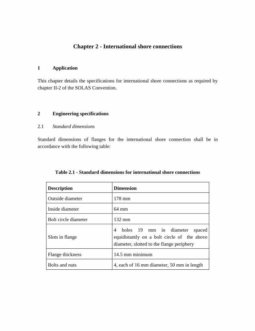
Standard dimensions of flanges for the international shore connection shall be in
accordance with the following table:
Table 2.1 - Standard dimensions for international shore connections
Description Dimension
Outside diameter 178 mm
Inside diameter 64 mm
Bolt circle diameter 132 mm
Slots in flange
4 holes 19 mm in diameter spaced
equidistantly on a bolt circle of the above
diameter, slotted to the flange periphery
Flange thickness 14.5 mm minimum
Bolts and nuts 4, each of 16 mm diameter, 50 mm in length

2.2 Materials and accessories
International shore connections shall be of steel or other equivalent material and shall be
designed for 1.0 N/mm² services. The flange shall have a flat face on one side and, on the
other side, it shall be permanently attached to a coupling that will fit the ship's hydrant
and hose. The connection shall be kept aboard the ship together with a gasket of any
material suitable for 1.0 N/mm² services, together with four bolts of 16 mm diameter and
50 mm in length, four 16 mm nuts, and eight washers.

Chapter 3 - Personnel protection
1 Application
This chapter details the specifications for personnel protection as required by chapter II-2
of the SOLAS Convention.
2 Engineering specifications
2.1 Fire-fighter's outfit
A fire-fighter's outfit shall consist of a set of personal equipment and a breathing
apparatus.
2.1.1 Personal equipment
Personal equipment shall consist of the following:
.1 protective clothing of material to protect the skin from the heat radiating
from the fire and from burns and scalding by steam. The outer surface
shall be water-resistant;
.2 boots of rubber or other electrically non-conducting material;
.3 rigid helmet providing effective protection against impact;
.4 electric safety lamp (hand lantern) of an approved type with a minimum
burning period of 3 hours. Electric safety lamps on tankers and those
intended to be used in hazardous areas shall be of an explosion-proof type;
and
.5 axe with a handle provided with high-voltage insulation.

2.1.2 Breathing apparatus
Breathing apparatus shall be a self-contained compressed air-operated breathing
apparatus for which the volume of air contained in the cylinders shall be at least 1,200
litres, or other self-contained breathing apparatus which shall be capable of functioning
for at least 30 min. All air cylinders for breathing apparatus shall be interchangeable.
2.1.3 Lifeline
For each breathing apparatus a fireproof lifeline of at least 30 m in length shall be
provided. The lifeline shall successfully pass an approval test by statical load of 3.5 kN
for 5 min without failure. The lifeline shall be capable of being attached by means of a
snap-hook to the harness of the apparatus or to a separate belt in order to prevent the
breathing apparatus becoming detached when the lifeline is operated.
2.2 Emergency escape breathing devices (EEBD)
2.2.1 General
2.2.1.1 An EEBD is a supplied-air or oxygen device only used for escape from a
compartment that has a hazardous atmosphere and shall be of an approved type.
2.2.1.2 EEBDs shall not be used for fighting fires, entering oxygen deficient voids or
tanks, or worn by fire-fighters. In these events, a self-contained breathing apparatus,
which is specifically suited for such applications, shall be used.
2.2.2 Definitions
2.2.2.1 Face piece means a face covering that is designed to form a complete seal around
the eyes, nose and mouth which is secured in position by a suitable means.
2.2.2.2 Hood means a head covering which completely covers the head, neck, and may
cover portions of the shoulders.
2.2.2.3 Hazardous atmosphere means any atmosphere that is immediately dangerous to
life or health.

2.2.3 Particulars
2.2.3.1 The EEBD shall have a service duration of at least 10 minutes.
2.2.3.2 The EEBD shall include a hood or full face piece, as appropriate, to protect the
eyes, nose and mouth during escape. Hoods and face pieces shall be constructed of flame
resistant materials and include a clear window for viewing.
2.2.3.3 An inactivated EEBD shall be capable of being carried hands-free.
2.2.3.4 An EEBD, when stored, shall be suitably protected from the environment.
2.2.3.5 Brief instructions or diagrams clearly illustrating their use shall be clearly printed
on the EEBD. The donning procedures shall be quick and easy to allow for situations
where there is little time to seek safety from a hazardous atmosphere.
2.2.4 Markings
Maintenance requirements, manufacturer’s trademarks and serial number, shelf life with
accompanying manufacture date and name of the approving authority shall be printed on
each EEBD. All EEBD training units shall be clearly marked.
Chapter 4 - Fire extinguishers
1 Application
This chapter details the specifications for fire extinguishers as required by chapter II-2 of
the SOLAS Convention.
2 Type approval
All fire extinguishers shall be of approved types and designs based on the guidelines
developed by the Organization.*
* Refer to the Improved Guidelines for marine portable fire extinguishers adopted by the
Organization by resolution A.951(23)
3 Engineering specifications
3.1 Fire extinguisher
3.1.1 Quantity of medium
3.1.1.1 Each powder or carbon dioxide extinguisher shall have a capacity of at least 5 kg,
and each foam extinguisher shall have a capacity of at least 9ℓ. The mass of all portable
fire extinguishers shall not exceed 23 kg, and they shall have a fire-extinguishing
capability at least equivalent to that of a 9ℓ fluid extinguisher.
3.1.1.2 The Administration shall determine the equivalents of fire extinguishers.
3.1.2 Recharging
Only refills approved for the fire extinguisher in question shall be used for recharging.
3.2 Portable foam applicators (Amended by Res.MSC.217(82))

3.2.1 A portable foam applicator unit shall consist of a foam nozzle/branch pipe, either
of a self-inducing type or in combination with a separate inductor, capable of being
connected to the fire main by a fire hose, together with a portable tank containing at least
20 liters of foam concentrate and at least one spare tank of foam concentrate of the same
capacity.
3.2.2 System performance
3.2.2.1 The nozzle/branch pipe and inductor shall be capable of producing effective foam
suitable for extinguishing an oil fire, at a foam solution flow rate of at least 200 ℓ/min at
the nominal pressure in the fire main.
3.2.2.2 The foam concentrate shall be approved by the Administration based on
guidelines developed by the Organization.*
* Refer to the Guidelines for the performance and testing criteria and surveys of low-
expansion foam concentrates for fixed fire-extinguishing systems (MSC/Circ.582/Corr.1
).
3.2.2.3 The values of the foam expansion and drainage time of the foam produced by the
portable foam applicator unit shall not differ more than ± 10% of that determined in
2.2.2.2.
3.2.2.4 The portable foam applicator unit shall be designed to withstand clogging,
ambient temperature changes, vibration, humidity, shock, impact and corrosion normally
encountered on ships.
(Amnded by Res.MSC.206(81))
Chapter 5 - Fixed gas fire-extinguishing systems
1 Application
This chapter details the specifications for fixed gas fire-extinguishing systems as required
by chapter II-2 of the Convention.
( Amended by Res.MSC.206(81))
2 Engineering specifications
2.1 General
2.1.1 Fire-extinguishing medium
2.1.1.1 Where the quantity of the fire-extinguishing medium is required to protect more
than one space, the quantity of medium available need not be more than the largest
quantity required for any one space so protected. The system shall be fitted with normally
closed control valves arranged to direct the agent into the appropriate space.
2.1.1.2 The volume of starting air receivers, converted to free air volume, shall be added
to the gross volume of the machinery space when calculating the necessary quantity of
the fire-extinguishing medium. Alternatively, a discharge pipe from the safety valves
may be fitted and led directly to the open air.
2.1.1.3 Means shall be provided for the crew to safely check the quantity of the fire-
extinguishing medium in the containers.
2.1.1.4 Containers for the storage of fire-extinguishing medium, piping and associated
pressure components shall be designed to pressure codes of practice to the satisfaction of
the Administration having regard to their locations and maximum ambient temperatures
expected in service.*
* Publication ISO - 9809/1: Refillable seamless steel gas cylinders (design,
construction and testing); ISO - 3500: Seamless steel CO2 cylinders. For fixed fire-
fighting installations on ships, specifying the principal external dimensions, accessories,
filling ratio and marking for seamless steel CO2 cylinders used in fixed fire-fighting

installations on ships, in order to facilitate their interchange ability; ISO - 5923: Fire
protection - Fire-extinguishing media - Carbon dioxide; ISO - 13769: Gas cylinders -
Stamp marking; ISO - 6406: Periodic inspection and testing of seamless steel gas
cylinders; ISO - 9329, part 1: Seamless steel tubes for pressure purposes - Technical
delivery conditions - Part 1: Unalloyed steels with specified room temperature
properties; ISO - 9329, part 2: Seamless steel tubes for pressure purposes - Technical
delivery conditions Part 2: Unalloyed and alloyed steels with specified elevated
temperature properties; ISO - 9330, part 1: Welded steel tubes for pressure
purposes - Technical delivery conditions - Part 1: Unalloyed steel tubes with specified
room temperature properties; ISO - 9330, part 2: Welded steel tubes for pressure
purposes - Technical delivery conditions - Part 2: Electric resistance and induction
welded unalloyed and alloyed steel tubes with specified elevated temperature
properties.
2.1.2 Installation requirements
2.1.2.1 The piping for the distribution of fire-extinguishing medium shall be arranged
and discharge nozzles so positioned that a uniform distribution of the medium is
obtained. System flow calculations shall be performed using a calculation technique
acceptable to the Administration.
2.1.2.2 Except as otherwise permitted by the Administration, pressure containers
required for the storage of fire-extinguishing medium, other than steam, shall be located
outside the protected spaces in accordance with regulation II-2/10.4.3 of the Convention.
2.1.2.3 Spare parts for the system shall be stored on board and be to the satisfaction of
the Administration.
2.1.2.4 In piping sections where valve arrangements introduce sections of closed piping,
such sections shall be fitted with a pressure relief valve and the outlet of the valve shall
be led to open deck.
2.1.2.5 All discharge piping, fittings and nozzles in the protected spaces shall be
constructed of materials having a melting temperature which exceeds 925°C. The piping
and associated equipment shall be adequately supported.
2.1.2.6 A fitting shall be installed in the discharge piping to permit the air testing as
required by paragraph 2.2.3.1.
2.1.3 System control requirements
2.1.3.1 The necessary pipes for conveying fire-extinguishing medium into the protected
spaces shall be provided with control valves so marked as to indicate clearly the spaces to
which the pipes are led. Suitable provisions shall be made to prevent inadvertent release
of the medium into the space. Where a cargo space fitted with a gas fire-extinguishing
system is used as a passenger space, the gas connection shall be blanked during such use.
The pipes may pass through accommodations providing that they are of substantial
thickness and that their tightness is verified with a pressure test, after their installation, at
a pressure head not less than 5 N/mm². In addition, pipes passing through accommodation
areas shall be joined only by welding and shall not be fitted with drains or other openings
within such spaces. The pipes shall not pass through refrigerated spaces.
2.1.3.2 Means shall be provided for automatically giving audible and visual warning of
the release of fire-extinguishing medium into any ro-ro spaces and other spaces in which
personnel normally work or to which they have access. The audible alarms shall be
located so as to be audible throughout the protected space with all machinery operating,
and the alarms should be distinguished from other audible alarms by adjustment of sound
pressure or sound patterns. The pre-discharge alarm shall be automatically activated (e.g.,
by opening of the release cabinet door). The alarm shall operate for the length of time
needed to evacuate the space, but in no case less than 20s before the medium is released.
Conventional cargo spaces and small spaces (such as compressor rooms, paint lockers,
etc.) with only a local release need not be provided with such an alarm.
2.1.3.3 The means of control of any fixed gas fire-extinguishing system shall be readily
accessible, simple to operate and shall be grouped together in as few locations as possible
at positions not likely to be cut off by a fire in a protected space. At each location there
shall be clear instructions relating to the operation of the system having regard to the
safety of personnel.
2.1.3.4 Automatic release of fire-extinguishing medium shall not be permitted, except as
permitted by the Administration.
( Amended by Res.MSC.206(81))
2.2 Carbon dioxide systems
2.2.1 Quantity of fire extinguishing medium
2.2.1.1 For cargo spaces, the quantity of carbon dioxide available shall, unless otherwise
provided, be sufficient to give a minimum volume of free gas equal to 30% of the gross
volume of the largest cargo space to be protected in the ship.
2.2.1.2 For machinery spaces, the quantity of carbon dioxide carried shall be sufficient to
give a minimum volume of free gas equal to the larger of the following volumes, either:
.1 40% of the gross volume of the largest machinery space so protected, the
volume to exclude that part of the casing above the level at which the
horizontal area of the casing is 40% or less of the horizontal area of the
space concerned taken midway between the tank top and the lowest part of
the casing; or
.2 35% of the gross volume of the largest machinery space protected,
including the casing.
2.2.1.3 The percentages specified in paragraph 2.2.1.2 above may be reduced to 35% and
30%, respectively, for cargo ships of less than 2,000 gross tonnage where two or more
machinery spaces, which are not entirely separate, are considered as forming one space.
2.2.1.4 For the purpose of this paragraph the volume of free carbon dioxide shall be
calculated at 0.56 m³/kg.
2.2.1.5 For machinery spaces the fixed piping system shall be such that 85% of the gas
can be discharged into the space within 2 min.
2.2.2 Controls
Carbon dioxide systems shall comply with the following requirements:
.1 two separate controls shall be provided for releasing carbon dioxide into a
protected space and to ensure the activation of the alarm. One control shall
be used for opening the valve of the piping which conveys the gas into the
protected space and a second control shall be used to discharge the gas
from its storage containers. Positive means shall be provided so they can
only be operated in that order; and

.2 the two controls shall be located inside a release box clearly identified for
the particular space. If the box containing the controls is to be locked, a
key to the box shall be in a break-glass-type enclosure conspicuously
located adjacent to the box.
2.2.3 Testing of the installation
When the system has been installed, pressure-tested and inspected, the following shall be
carried out:
.1 a test of the free air flow in all pipes and nozzles; and
.2 a functional test of the alarm equipment.
2.2.4 Low-pressure CO2 system
Where a low pressure CO2 system is fitted to comply with this regulation, the following
applies.
2.2.4.1 The system control devices and the refrigerating plants shall be located within the
same room where the pressure vessels are stored.
2.2.4.2 The rated amount of liquid carbon dioxide shall be stored in vessel(s) under the
working pressure in the range of 1.8 N/mm² to 2.2 N/mm². The normal liquid charge in
the container shall be limited to provide sufficient vapour space to allow for expansion of
the liquid under the maximum storage temperatures than can be obtained corresponding
to the setting of the pressure relief valves but shall not exceed 95% of the volumetric
capacity of the container.
2.2.4.3 Provision shall be made for:
.1 pressure gauge;
.2 high pressure alarm: not more than setting of the relief valve;
.3 low pressure alarm: not less than 1.8 N/mm²;
.4 branch pipes with stop valves for filling the vessel;
.5 discharge pipes;

.6 liquid CO2 level indicator, fitted on the vessel(s); and
.7 two safety valves.
2.2.4.4 The two safety relief valves shall be arranged so that either valve can be shut off
while the other is connected to the vessel. The setting of the relief valves shall not be less
than 1.1 times working pressure. The capacity of each valve shall be such that the
vapours generated under fire condition can be discharged with a pressure rise not more
than 20% above the setting pressure. The discharge from the safety valves shall be led to
the open.
2.2.4.5 The vessel(s) and outgoing pipes permanently filled with carbon dioxide shall
have thermal insulation preventing the operation of the safety valve in 24 h after de-
energizing the plant, at ambient temperature of 45°C and an initial pressure equal to the
starting pressure of the refrigeration unit.
2.2.4.6 The vessel(s) shall be serviced by two automated completely independent
refrigerating units solely intended for this purpose, each comprising a compressor and the
relevant prime mover, evaporator and condenser.
2.2.4.7 The refrigerating capacity and the automatic control of each unit shall be so as to
maintain the required temperature under conditions of continuous operation during 24 h
at sea temperatures up to 32°C and ambient air temperatures up to 45°C.
2.2.4.8 Each electric refrigerating unit shall be supplied from the main switchboard
busbars by a separate feeder.
2.2.4.9 Cooling water supply to the refrigerating plant (where required) shall be provided
from at least two circulating pumps one of which being used as a stand-by. The stand-by
pump may be a pump used for other services so long as its use for cooling would not
interfere with any other essential service of the ship. Cooling water shall be taken from
not less than two sea connections, preferably one port and one starboard.
2.2.4.10 Safety relief devices shall be provided in each section of pipe that may be
isolated by block valves and in which there could be a build-up of pressure in excess of
the design pressure of any of the components.
2.2.4.11 Audible and visual alarms shall be given in a central control station or, in
accordance with regulation II-1/51, where a central control station is not provided, when:
.1 the pressure in the vessel(s) reaches the low and high values according to
paragraph 2.2.4.2;
.2 any one of the refrigerating units fails to operate; or
.3 the lowest permissible level of the liquid in the vessels is reached.
2.2.4.12 If the system serves more than one space, means for control of discharge
quantities of CO2 shall be provided, e.g. automatic timer or accurate level indicators
located at the control position(s).
2.2.4.13 If a device is provided which automatically regulates the discharge of the rated
quantity of carbon dioxide into the protected spaces, it shall be also possible to regulate
the discharge manually.
(Amended by Res.MSC.206(81))
2.3 Requirements of steam systems
The boiler or boilers available for supplying steam shall have an evaporation of at least 1
kg of steam per hour for each 0.75 m³ of the gross volume of the largest space so
protected. In addition to complying with the foregoing requirements, the systems in all
respects shall be as determined by, and to the satisfaction of, the Administration.
(Amended by Res.MSC.206(81))
2.4 Systems using gaseous products of fuel combustion
2.4.1 General
Where gas other than carbon dioxide or steam, as permitted by paragraph 2.3, is produced
on the ship and is used as a fire-extinguishing medium, the system shall comply with the
requirements in paragraph 2.4.2.

2.4.2 Requirements of the systems
2.4.2.1 Gaseous products
Gas shall be a gaseous product of fuel combustion in which the oxygen content, the
carbon monoxide content, the corrosive elements and any solid combustible elements in a
gaseous product shall have been reduced to a permissible minimum.
2.4.2.2 Capacity of fire -extinguishing systems
2.4.2.2.1Where such gas is used as the fire-extinguishing medium in a fixed fire-
extinguishing system for the protection of machinery spaces, it shall afford protection
equivalent to that provided by a fixed system using carbon dioxide as the medium.
2.4.2.2.2Where such gas is used as the fire-extinguishing medium in a fixed fire-
extinguishing system for the protection of cargo spaces, a sufficient quantity of such gas
shall be available to supply hourly a volume of free gas at least equal to 25% of the gross
volume of the largest space protected in this way for a period of 72 h.
(Amended by Res.MSC.206(81))
2.5 Equivalent fixed gas fire-extinguishing systems for machinery spaces and cargo
pump-rooms
Fixed gas fire-extinguishing systems equivalent to those specified in paragraphs 2.2 to
2.4 shall be approved by the Administration based on the guidelines developed by the
Organization.*
* Refer to the Revised guidelines for the approval of equivalent fixed gas fire-
extinguishing systems, as referred to in SOLAS 74, for machinery spaces and cargo
pump rooms (MSC/Circ.848) and the Guidelines for the approval of fixed aerosol fire-
extinguishing systems equivalent to fixed gas fire-extinguishing systems, as referred to
in SOLAS 74, for machinery spaces (MSC/Circ.1007).
Chapter 6 - Fixed foam fire-extinguishing systems
1 Application
This chapter details the specifications for fixed foam fire-extinguishing systems as
required by chapter II-2 of the SOLAS Convention.
2 Engineering specifications
2.1 General
Fixed foam fire-extinguishing systems shall be capable of generating foam suitable for
extinguishing oil fires.
2.2 Fixed high-expansion foam fire-extinguishing systems
2.2.1 Quantity and performance of foam concentrates
2.2.1.1 The foam concentrates of high-expansion foam fire-extinguishing systems shall
be approved by the Administration based on the guideline developed by the
Organization.*
* Refer to the Guidelines for performance and testing criteria and surveys of high
expansion foam concentrates for fixed fire-extinguishing systems (MSC/ Circ.670).
2.2.1.2 Any required fixed high-expansion foam system in machinery spaces shall be
capable of rapidly discharging through fixed discharge outlets a quantity of foam
sufficient to fill the greatest space to be protected at a rate of at least 1 m in depth per
minute. The quantity of foam-forming liquid available shall be sufficient to produce a
volume of foam equal to five times the volume of the largest space to be protected. The
expansion ratio of the foam shall not exceed 1,000 to 1.
2.2.1.3 The Administration may permit alternative arrangements and discharge rates
provided that it is satisfied that equivalent protection is achieved.
2.2.2 Installation requirements
2.2.2.1 Supply ducts for delivering foam, air intakes to the foam generator and the
number of foam-producing units shall in the opinion of the Administration be such as will
provide effective foam production and distribution.
2.2.2.2 The arrangement of the foam generator delivery ducting shall be such that a fire
in the protected space will not affect the foam generating equipment. If the foam
generators are located adjacent to the protected space, foam delivery ducts shall be
installed to allow at least 450 mm of separation between the generators and the protected
space. The foam delivery ducts shall be constructed of steel having a thickness of not less
than 5 mm. In addition, stainless steel dampers (single or multi-bladed) with a thickness
of not less than 3 mm shall be installed at the openings in the boundary bulkheads or
decks between the foam generators and the protected space. The dampers shall be
automatically operated (electrically, pneumatically or hydraulically) by means of remote
control of the foam generator related to them.
2.2.2.3 The foam generator, its sources of power supply, foam-forming liquid and means
of controlling the system shall be readily accessible and simple to operate and shall be
grouped in as few locations as possible at positions not likely to be cut off by a fire in the
protected space.
2.3 Fixed low-expansion foam fire-extinguishing systems
2.3.1 Quantity and foam concentrates
2.3.1.1 The foam concentrates of low-expansion foam fire-extinguishing systems shall be
approved by the Administration based on the guidelines developed by the Organization.*
* Refer to the Guidelines for the performance and testing criteria and surveys of low
expansion foam concentrates for fixed fire-extinguishing systems (MSC/ Circ.582 and
Corr.1).
2.3.1.2 The system shall be capable of discharging through fixed discharge outlets in not
more than 5 min, a quantity of foam sufficient produce an effective foam blanket over the
largest single area over which oil fuel is liable to spread. ( Amended by
Res.MSC.217(82)).
2.3.2 Installation requirements
2.3.2.1 Means shall be provided for the effective distribution of the foam through a
permanent system of piping and control valves or cocks to suitable discharge outlets, and
for the foam to be effectively directed by fixed sprayers onto other main fire hazards in
the protected space. The means for effective distribution of the foam shall be proven
acceptable to the Administration through calculation or by testing.
2.3.2.2 The means of control of any such systems shall be readily accessible and simple
to operate and shall be grouped together in as few locations as possible at positions not
likely to be cut off by a fire in the protected space.

Chapter 7 - Fixed pressure water-spraying and water-mist fire-
extinguishing systems
1 Application
This chapter details the specifications for fixed pressure water-spraying and water-mist
fire-extinguishing systems as required by chapter II-2 of the SOLAS Convention.
( Amended by Res.MSC.217(82))
2 Engineering specifications
2.1 Fixed pressure water-spraying fire-extinguishing systems
Fixed-pressure water-spraying fire-extinguishing systems for machinery spaces and cargo
pump-rooms shall be approved by the Administration based on the guidelines developed
by the Organization.*
* Refer to the Revised Guidelines for the approval of equivalent water-based fire-
extinguishing systems for machinery spaces and cargo pump-rooms (MSC/Circ.1165 .
(Amended by Res.MSC.217(82))
2.2 Equivalent water-mist fire-extinguishing systems
Water-mist fire-extinguishing systems for machinery spaces and cargo pump-rooms shall
be approved by the Administration based on the guidelines developed by the
Organization.*
* Refer to the alternative arrangements for halon fire-extinguishing systems in
machinery spaces and pump-rooms (MSC/Circ. 668) and the revised Test method for
equivalent water-based fire-extinguishing systems for machinery spaces of category A
and cargo pump-rooms contained in MSC/Circ. 668 (MSC/Circ. 728). The above circulars
are valid until 10 June 2010 when the revised refer to the Revised Guidelines for the
approval of equivalent water-based fire-extinguishing systems for machinery spaces and
cargo pump-rooms (MSC/Circ.1165) become effective.
(Amended by Res.MSC.217(82))
2.3 Fixed pressure water-spraying fire-extinguishing systems for cabin balconies
Fixed pressure water-spraying fire-extinguishing systems for cabin balconies shall be
approved by the Administration based on the guidelines developed by the Organization.*
* Refer to the guidelines to be developed by the Organization.

Chapter 8 - Automatic sprinkler, fire detection and fire alarm systems
1 Application
This chapter details the specifications for automatic sprinkler, fire detection and fire
alarm systems as required by chapter II-2 of the SOLAS Convention.
2 Engineering specifications
2.1 General
2.1.1 Type of sprinkler systems
The automatic sprinkler systems shall be of the wet pipe type, but small exposed sections
may be of the dry pipe type where in the opinion of the Administration this is a necessary
precaution. Saunas shall be fitted with a dry pipe system, with sprinkler heads having an
operating temperature up to 140°C.
2.1.2 Sprinkler systems equivalent to those specified in paragraphs 2.2 to 2.4
Automatic sprinkler systems equivalent to those specified in paragraphs 2.2 to 2.4 shall
be approved by the Administration based on the guidelines developed by the
Organization.*
* Refer to the Revised Guidelines for approval of sprinkler systems equivalent to that
referred to in SOLAS regulation II-2/12 as adopted by the Organization by resolution
A.800(19).
2.2 Sources of power supply
2.2.1 Passenger ships
There shall be not less than two sources of power supply for the sea water pump and
automatic alarm and detection system. Where the sources of power for the pump are
electrical, these shall be a main generator and an emergency source of power. One supply
for the pump shall be taken from the main switchboard, and one from the emergency

switchboard by separate feeders reserved solely for that purpose. The feeders shall be so
arranged as to avoid galleys, machinery spaces and other enclosed spaces of high fire risk
except in so far as it is necessary to reach the appropriate switchboards, and shall be run
to an automatic changeover switch situated near the sprinkler pump. This switch shall
permit the supply of power from the main switchboard so long as a supply is available
therefrom, and be so designed that upon failure of that supply it will automatically
change over to the supply from the emergency switchboard. The switches on the main
switchboard and the emergency switchboard shall be clearly labelled and normally kept
closed. No other switch shall be permitted in the feeders concerned. One of the sources of
power supply for the alarm and detection system shall be an emergency source. Where
one of the sources of power for the pump is an internal combustion engine it shall, in
addition to complying with the provisions of paragraph 2.4.3, be so situated that a fire in
any protected space will not affect the air supply to the machinery.
2.2.2 Cargo ships
There shall not be less than two sources of power supply for the sea water pump and
automatic alarm and detection system. If the pump is electrically driven it shall be
connected to the main source of electrical power, which shall be capable of being
supplied by at least two generators. The feeders shall be so arranged as to avoid galleys,
machinery spaces and other enclosed spaces of high fire risk except in so far as it is
necessary to reach the appropriate switchboards. One of the sources of power supply for
the alarm and detection system shall be an emergency source. Where one of the sources
of power for the pump is an internal combustion engine it shall, in addition to complying
with the provisions of paragraph 2.4.3, be so situated that a fire in any protected space
will not affect the air supply to the machinery.
2.3 Component requirements
2.3.1 Sprinklers
2.3.1.1 The sprinklers shall be resistant to corrosion by marine atmosphere. In
accommodation and service spaces the sprinklers shall come into operation within the
temperature range from 68°C to 79°C, except that in locations such as drying rooms,
where high ambient temperatures might be expected, the operating temperature may be
increased by not more than 30°C above the maximum deckhead temperature.
2.3.1.2 A quantity of spare sprinkler heads shall be provided for all types and ratings
installed on the ship as follows:

Total number of heads Required number of spares
<300 6
300 ~ 1000 12
>1000 24
The number of spare sprinkler heads of any type need not exceed the total number of
heads installed of that type.
2.3.2 Pressure tanks
2.3.2.1 A pressure tank having a volume equal to at least twice that of the charge of
water specified in this paragraph shall be provided. The tank shall contain a standing
charge of fresh water, equivalent to the amount of water which would be discharged in
one minute by the pump referred to in paragraph 2.3.3.2, and the arrangements shall
provide for maintaining an air pressure in the tank such as to ensure that where the
standing charge of fresh water in the tank has been used the pressure will be not less than
the working pressure of the sprinkler, plus the pressure exerted by a head of water
measured from the bottom of the tank to the highest sprinkler in the system. Suitable
means of replenishing the air under pressure and of replenishing the fresh water charge in
the tank shall be provided. A glass gauge shall be provided to indicate the correct level of
the water in the tank.
2.3.2.2 Means shall be provided to prevent the passage of sea water into the tank.
2.3.3 Sprinkler pumps
2.3.3.1 An independent power pump shall be provided solely for the purpose of
continuing automatically the discharge of water from the sprinklers. The pump shall be
brought into action automatically by the pressure drop in the system before the standing
fresh water charge in the pressure tank is completely exhausted.
2.3.3.2 The pump and the piping system shall be capable of maintaining the necessary
pressure at the level of the highest sprinkler to ensure a continuous output of water
sufficient for the simultaneous coverage of a minimum area of 280 m² at the application
rate specified in paragraph 2.5.2.3. The hydraulic capability of the system shall be
confirmed by the review of hydraulic calculations, followed by a test of the system, if
deemed necessary by the Administration.
2.3.3.3 The pump shall have fitted on the delivery side a test valve with a short open-
ended discharge pipe. The effective area through the valve and pipe shall be adequate to
permit the release of the required pump output while maintaining the pressure in the
system specified in paragraph 2.3.2.1.
2.4 Installation requirements
2.4.1 General
Any parts of the system which may be subjected to freezing temperatures in service shall
be suitably protected against freezing.
2.4.2 Piping arrangements
2.4.2.1 Sprinklers shall be grouped into separate sections, each of which shall contain not
more than 200 sprinklers. In passenger ships any section of sprinklers shall not serve
more than two decks and shall not be situated in more than one main vertical zone.
However, the Administration may permit such a section of sprinklers to serve more than
two decks or be situated in more than one main vertical zone, if it is satisfied that the
protection of the ship against fire will not thereby be reduced.
2.4.2.2 Each section of sprinklers shall be capable of being isolated by one stop valve
only. The stop valve in each section shall be readily accessible in a location outside of the
associated section or in cabinets within stairway enclosures. The valve's location shall be
clearly and permanently indicated. Means shall be provided to prevent the operation of
the stop valves by any unauthorized person.
2.4.2.3 A test valve shall be provided for testing the automatic alarm for each section of
sprinklers by a discharge of water equivalent to the operation of one sprinkler. The test
valve for each section shall be situated near the stop valve for that section.
2.4.2.4 The sprinkler system shall have a connection from the ship's fire main by way of
a lockable screw-down non-return valve at the connection which will prevent a backflow
from the sprinkler system to the fire main.
2.4.2.5 A gauge indicating the pressure in the system shall be provided at each section
stop valve and at a central station.
2.4.2.6 The sea inlet to the pump shall wherever possible be in the space containing the
pump and shall be so arranged that when the ship is afloat it will not be necessary to shut
off the supply of sea water to the pump for any purpose other than the inspection or repair
of the pump.
2.4.3 Location of systems
The sprinkler pump and tank shall be situated in a position reasonably remote from any
machinery space of category A and shall not be situated in any space required to be
protected by the sprinkler system.
2.5 System control requirements
2.5.1 Ready availability
2.5.1.1 Any required automatic sprinkler, fire detection and fire alarm system shall be
capable of immediate operation at all times and no action by the crew shall be necessary
to set it in operation.
2.5.1.2 The automatic sprinkler system shall be kept charged at the necessary pressure
and shall have provision for a continuous supply of water as required in this chapter.
2.5.2 Alarm and indication
2.5.2.1 Each section of sprinklers shall include means for giving a visual and audible
alarm signal automatically at one or more indicating units whenever any sprinkler comes
into operation. Such alarm systems shall be such as to indicate if any fault occurs in the
system. Such units shall indicate in which section served by the system a fire has
occurred and shall be centralised on the navigation bridge or in the continuously manned
central control station and, in addition, visible and audible alarms from the unit shall also
be placed in a position other than on the aforementioned spaces to ensure that the
indication of fire is immediately received by the crew.
2.5.2.2 Switches shall be provided at one of the indicating positions referred to in
paragraph 2.5.2.1 which will enable the alarm and the indicators for each section of
sprinklers to be tested.
2.5.2.3 Sprinklers shall be placed in an overhead position and spaced in a suitable pattern
to maintain an average application rate of not less than 5ℓ/m²/min over the nominal area
covered by the sprinklers. However, the Administration may permit the use of sprinklers
providing such an alternative amount of water suitably distributed as has been shown to
the satisfaction of the Administration to be not less effective.

2.5.2.4 A list or plan shall be displayed at each indicating unit showing the spaces
covered and the location of the zone in respect of each section. Suitable instructions for
testing and maintenance shall be available.
2.5.3 Testing
Means shall be provided for testing the automatic operation of the pump on reduction of
pressure in the system.

Chapter 9 - Fixed fire detection and fire alarm systems
1 Application
1.1 This chapter details the specification of fixed fire detection and fire alarm systems
as required by chapter II-2 of the Convention. Unless expressly provided otherwise, the
requirements of this chapter shall apply to ships constructed on or after 1 July 2012.
1.2 Definitions
1.2.1 Section means a group of fire detectors and manually operated call points as
reported in the indicating unit(s).
1.2.2 Section identification capability means a system with the capability of identifying
the section in which a detector or manually operated call point has activated.
1.2.3 Individually identifiable means a system with the capability to identify the exact
location and type of detector or manually activated call point which has activated, and
which can differentiate the signal of that device from all others.
2 Engineering specifications
2.1 General requirements
2.1.1 Any required fixed fire detection and fire alarm system with manually operated
call points shall be capable of immediate operation at all times (this does not require a
backup control panel). Notwithstanding this, particular spaces may be disconnected, for
example, workshops during hot work and ro-ro spaces during on and off-loading. The
means for disconnecting the detectors shall be designed to automatically restore the
system to normal surveillance after a predetermined time that is appropriate for the
operation in question. The space shall be manned or provided with a fire patrol when
detectors required by regulation are disconnected. Detectors in all other spaces shall
remain operational.
2.1.2 The fire detection system shall be designed to:
.1 control and monitor input signals from all connected fire and smoke
detectors and manual call points;
.2 provide output signals to the navigation bridge, continuously manned
central control station or onboard safety centre to notify the crew of fire
and fault conditions;
.3 monitor power supplies and circuits necessary for the operation of the
system for loss of power and fault conditions; and
.4 the system may be arranged with output signals to other fire safety
systems including:
.1 paging systems, fire alarm or public address systems;
.2 fan stops;
.3 fire doors;
.4 fire dampers;
.5 sprinkler systems;
.6 smoke extraction systems;
.7 low-location lighting systems;
.8 fixed local application fire-extinguishing systems;
.9 closed circuit television (CCTV) systems; and
.10 other fire safety systems.
2.1.3 The fire detection system may be connected to a decision management system
provided that:
.1 the decision management system is proven to be compatible with the fire
detection system;

.2 the decision management system can be disconnected without losing any
of the functions required by this chapter for the fire detection system; and
.3 any malfunction of the interfaced and connected equipment should not
propagate under any circumstance to the fire detection system.
2.1.4 Detectors and manual call points shall be connected to dedicated sections of the
fire detection system. Other fire safety functions, such as alarm signals from the sprinkler
valves, may be permitted if in separate sections.
2.1.5 The system and equipment shall be suitably designed to withstand supply voltage
variation and transients, ambient temperature changes, vibration, humidity, shock, impact
and corrosion normally encountered in ships. All electrical and electronic equipment on
the bridge or in the vicinity of the bridge shall be tested for electromagnetic
compatibility, taking into account the recommendations developed by the Organization.*
* Refer to the General requirements for electromagnetic compatibility for all electrical
and electronic equipment, adopted by the Organization by resolution A.813(19).
2.1.6 Fixed fire detection and fire alarm systems with individually identifiable fire
detectors shall be so arranged that:
.1 means are provided to ensure that any fault (e.g., power break, short
circuit, earth, etc.) occurring in the section will not prevent the continued
individual identification of the remainder of the connected detectors in the
section;
.2 all arrangements are made to enable the initial configuration of the system
to be restored in the event of failure (e.g., electrical, electronic,
informatics, etc.);
.3 the first initiated fire alarm will not prevent any other detector from
initiating further fire alarms; and
.4 no section will pass through a space twice. When this is not practical (e.g.,
for large public spaces), the part of the section which by necessity passes
through the space for a second time shall be installed at the maximum
possible distance from the other parts of the section.

2.1.7 In passenger ships, the fixed fire detection and fire alarm system shall be capable
of remotely and individually identifying each detector and manually operated call point.
Fire detectors fitted in passenger ship cabins, when activated, shall also be capable of
emitting, or cause to be emitted, an audible alarm within the space where they are
located. In cargo ships and on passenger ship cabin balconies the fixed fire detection and
fire alarm system shall, as a minimum, have section identification capability.
2.2 Sources of power supply
2.2.1 There shall be not less than two sources of power supply for the electrical
equipment used in the operation of the fixed fire detection and fire alarm system, one of
which shall be an emergency source of power. The supply shall be provided by separate
feeders reserved solely for that purpose. Such feeders shall run to an automatic change-
over switch situated in or adjacent to the control panel for the fire detection system. The
main (respective emergency) feeder shall run from the main (respective emergency)
switchboard to the change-over switch without passing through any other distributing
switchboard.
2.2.2 There shall be sufficient power to permit the continued operation of the system
with all detectors activated, but not more than 100 if the total exceeds this figure.
2.2.3 The emergency source of power specified in paragraph 2.2.1 above shall be
sufficient to maintain the operation of the fire detection and fire alarm system for the
periods required under regulations II-1/42 and 43 of the Convention, and at the end of
that period, shall be capable of operating all connected visual and audible fire alarm
signals for a period of at least 30 min.
2.3 Component requirements
2.3.1 Detectors
2.3.1.1 Detectors shall be operated by heat, smoke or other products of combustion,
flame, or any combination of these factors. Detectors operated by other factors indicative
of incipient fires may be considered by the Administration provided that they are no less
sensitive than such detectors.
2.3.1.2 Smoke detectors required in all stairways, corridors and escape routes within
accommodation spaces shall be certified to operate before the smoke density exceeds
12.5% obscuration per metre, but not until the smoke density exceeds 2% obscuration per
metre. when tested according to standards EN 54:2001 and IEC 60092-505:2001.
Alternative testing standards may be used as determined by the Administration. Smoke
detectors to be installed in other spaces shall operate within sensitivity limits to the
satisfaction of the Administration having regard to the avoidance of detector insensitivity
or oversensitivity.
2.3.1.3 Heat detectors shall be certified to operate before the temperature exceeds 78ºC
but not until the temperature exceeds 54ºC, when the temperature is raised to those limits
at a rate less than 1ºC per min. when tested according to standards EN 54:2001 and IEC
60092-505:2001. Alternative testing standards may be used as determined by the
Administration. At higher rates of temperature rise, the heat detector shall operate within
temperature limits to the satisfaction of the Administration having regard to the
avoidance of detector insensitivity or oversensitivity.
2.3.1.4 The operation temperature of heat detectors in drying rooms and similar spaces
of a normal high ambient temperature may be up to 130ºC, and up to 140ºC in saunas.
2.3.1.5 Flame detectors shall be tested according to standards EN 54-10:2001 and IEC
60092-505:2001. Alternative testing standards may be used as determined by the
Administration.
2.3.1.6 All detectors shall be of a type such that they can be tested for correct operation
and restored to normal surveillance without the renewal of any component.
2.3.1.7 Fixed fire detection and fire alarm systems for cabin balconies shall be approved
by the Administration, based on the guidelines developed by the Organization.*
* Refer to the Guidelines for approval of fixed fire detection and fire alarm systems for
cabin balconies (MSC.1/Circ.1242).
2.3.1.8 Detectors fitted in hazardous areas shall be tested and approved for such service.
Detectors required by regulation II-2/20.4 and installed in spaces that comply with
regulation II-2/20.3.2.2 of the Convention need not be suitable for hazardous areas.
Detectors fitted in spaces carrying dangerous goods, required by regulation II-2/19, table
19.3, of the Convention to comply with regulation II-2/19.3.2 of the Convention, shall be
suitable for hazardous areas.
2.3.2 Control panel
The control panel for the fire detection system shall be tested according to standards EN
54-2:1997, EN 54-4:1997 and IEC 60092-504:2001. Alternative standards may be used
as determined by the Administration.
2.3.3 Cables
Cables used in the electrical circuits shall be flame retardant according to standard IEC
60332-1. On passenger ships, cables routed through other main vertical zones that they
serve, and cables to control panels in an unattended fire control station shall be fire
resisting according to standard IEC 60331, unless duplicated and well separated.
2.4 Installation requirements
2.4.1 Sections
2.4.1.1 Detectors and manually operated call points shall be grouped into sections.
2.4.1.2 A section of fire detectors which covers a control station, a service space or an
accommodation space shall not include a machinery space of category A or a ro-ro space.
A section of fire detectors which covers a ro-ro space shall not include a machinery space
of category A. For fixed fire detection systems with remotely and individually
identifiable fire detectors, a section covering fire detectors in accommodation, service
spaces and control stations shall not include fire detectors in machinery spaces of
category A or ro-ro spaces.
2.4.1.3 Where the fixed fire detection and fire alarm system does not include means of
remotely identifying each detector individually, no section covering more than one deck
within accommodation spaces, service spaces and control stations shall normally be
permitted except a section which covers an enclosed stairway. In order to avoid delay in
identifying the source of fire, the number of enclosed spaces included in each section
shall be limited as determined by the Administration. If the detection system is fitted with
remotely and individually identifiable fire detectors, the sections may cover several decks
and serve any number of enclosed spaces.
2.4.1.4 In passenger ships, a section of detectors and manually operated call points shall
not be situated in more than one main vertical zone, except on cabin balconies.

2.4.2 Positioning of detectors
2.4.2.1 Detectors shall be located for optimum performance. Positions near beams and
ventilation ducts, or other positions where patterns of air flow could adversely affect
performance, and positions where impact or physical damage is likely, shall be avoided.
Detectors shall be located on the overhead at a minimum distance of 0.5 m away from
bulkheads, except in corridors, lockers and stairways.
2.4.2.2 The maximum spacing of detectors shall be in accordance with the table below:
Table 9.1 – Spacing of detectors
Type of detector
Maximum floor
area per detector
(m2)
Maximum
distance
apart
between
centres (m)
Maximum distance away
from bulkheads (m)
Heat 37 9 4.5
Smoke 74 11 5.5
The Administration may require or permit other spacing based upon test data which
demonstrate the characteristics of the detectors. Detectors located below moveable ro-ro
decks shall be in accordance with the above.
2.4.2.3 Detectors in stairways shall be located at least at the top level of the stair and at
every second level beneath.
2.4.2.4 When fire detectors are installed in freezers, drying rooms, saunas, parts of
galleys used to heat food, laundries and other spaces where steam and fumes are
produced, heat detectors may be used.
2.4.2.5 Where a fixed fire detection and fire alarm system is required by regulation II-
2/7.5 of the Convention, spaces having little or no fire risk need not be fitted with
detectors. Such spaces include void spaces with no storage of combustibles, private
bathrooms, public toilets, fire-extinguishing medium storage rooms, cleaning gear lockers
(in which flammable liquids are not stowed), open deck spaces and enclosed promenades
having little or no fire risk and that are naturally ventilated by permanent openings.

2.4.3 Arrangement of cables
2.4.3.1 Cables which form part of the system shall be so arranged as to avoid galleys,
machinery spaces of category A, and other enclosed spaces of high fire risk except where
it is necessary to provide for fire detection or fire alarms in such spaces or to connect to
the appropriate power supply.
2.4.3.2 A section with individually identifiable capability shall be arranged so that it
cannot be damaged at more than one point by a fire.
2.5 System control requirements
2.5.1 Visual and audible fire signals*
* Refer to the Code on Alerts and Indicators, 2009, as adopted by the Organization by
resolution A. 1021(26).
2.5.1.1 The activation of any detector or manually operated call point shall initiate a
visual and audible fire detection alarm signal at the control panel and indicating units. If
the signals have not been acknowledged within 2 min, an audible fire alarm shall be
automatically sounded throughout the crew accommodation and service spaces, control
stations and machinery spaces of category A. This alarm sounder system need not be an
integral part of the detection system.
2.5.1.2 In passenger ships, the control panel shall be located in the onboard safety centre.
In cargo ships, the control panel shall be located on the navigation bridge or in the fire
control station.
2.5.1.3 In passenger ships, an indicating unit that is capable of individually identifying
each detector that has been activated or manually operated call point that has operated
shall be located on the navigation bridge. In cargo ships, an indicating unit shall be
located on the navigation bridge if the control panel is located in the fire control station.
In cargo ships and on passenger cabin balconies, Indicating units shall, as a minimum,
denote the section in which a detector has activated or manually operated call point has
operated.
2.5.1.4 Clear information shall be displayed on or adjacent to each indicating unit about
the spaces covered and the location of the sections.
2.5.1.5 Power supplies and electric circuits necessary for the operation of the system
shall be monitored for loss of power and fault conditions as appropriate including:
.1 a single open or power break fault caused by a broken wire;
.2 a single ground fault caused by the contact of a wiring conductor to a
metal component; and
.3 a single wire to wire fault caused by the contact of two or more wiring
conductors.
Occurrence of a fault condition shall initiate a visual and audible fault signal at the
control panel which shall be distinct from a fire signal.
2.5.1.6 Means to manually acknowledge all alarm and fault signals shall be provided at
the control panel. The audible alarm sounders on the control panel and indicating units
may be manually silenced. The control panel shall clearly distinguish between normal,
alarm, acknowledged alarm, fault and silenced conditions.
2.5.1.7 The system shall be arranged to automatically reset to the normal operating
condition after alarm and fault conditions are cleared.
2.5.1.8 When the system is required to sound a local audible alarm within the cabins
where the detectors are located, a means to silence the local audible alarms from the
control panel shall not be permitted.
2.5.1.9 In general, audible alarm sound pressure levels at the sleeping positions in the
cabins and 1 m from the source shall be at least 75 dB(A) and at least 10 dB(A) above
ambient noise levels existing during normal equipment operation with the ship under way
in moderate weather. The sound pressure level should be in the 1/3 octave band about the
fundamental frequency. Audible alarm signals shall not exceed 120 dB(A).
2.5.2 Testing
Suitable instructions and component spares for testing and maintenance shall be
provided. Detectors shall be periodically tested using equipment suitable for the types of
fires to which the detector is designed to respond. Ships with self-diagnostic systems that
have in place a cleaning regime for areas where heads may be prone to contamination
may carry out testing in accordance with the requirements of the Administration.

2.6 Fixed Fire-Detection and Fire Alarm Systems for Cabin Balconies
Fixed Fire-Detection and Fire Alarm Systems for Cabin Balconies shall be approved by
the Administration based on the guidelines developed by the Organisation.*
* Refer to the guidelines to be developed by the Organisation.
Chapter 10 - Sample extraction smoke detection systems
1 Application
This chapter details the specification of sample extraction smoke detection systems in
cargo spaces as required by chapter II-2 of the Convention. Unless expressly provided
otherwise, the requirements of this chapter shall apply to ships constructed on or after 1
January 2012.
2 Engineering specifications
2.1 General requirements
2.1.1 Wherever in the text of this chapter the word "system" appears, it shall mean
"sample extraction smoke detection system".
2.1.1.1 A sample extraction smoke detection system consists of the following main
components:
.1 smoke accumulators: air collection devices installed at the open ends of
the sampling pipes in each cargo hold that perform the physical function
of collecting air samples for transmission to the control panel through the
sampling pipes, and may also act as discharge nozzles for the fixed-gas
fire-extinguishing system, if installed;
.2 sampling pipes: a piping network that connects the smoke accumulators to
the control panel, arranged in sections to allow the location of the fire to
be readily identified;
.3 three-way valves: if the system is interconnected to a fixed-gas fire-
extinguishing system, three-way valves are used to normally align the
sampling pipes to the control panel and, if a fire is detected, the three-way
valves are re-aligned to connect the sampling pipes to the fire-
extinguishing system discharge manifold and isolate the control panel; and
.4 control panel: the main element of the system which provides continuous
monitoring of the protected spaces for indication of smoke. It typically
may include a viewing chamber or smoke sensing units. Extracted air from
the protected spaces is drawn through the smoke accumulators and
sampling pipes to the viewing chamber, and then to the smoke sensing
chamber where the airstream is monitored by electrical smoke detectors. If
smoke is sensed, the repeater panel (normally on the bridge) automatically
sounds an alarm (not localized). The crew can then determine at the smoke
sensing unit which cargo hold is on fire and operate the pertinent three-
way valve for discharge of the extinguishing agent.
2.1.2 Any required system shall be capable of continuous operation at all times except
that systems operating on a sequential scanning principle may be accepted, provided that
the interval between scanning the same position twice gives an overall response time to
the satisfaction of the administration. a maximum allowable interval determined as
follows:
The interval (I) should depend on the number of scanning points (N) and the response
time of the fans (T), with a 20% allowance:
I = 1.2 x T x N
However, the maximum allowable interval should not exceed 120 s (Imax = 120 s).
2.1.3 The system shall be designed, constructed and installed so as to prevent the
leakage of any toxic or flammable substances or fire-extinguishing media into any
accommodation and space, service space, control station or machinery space.
2.1.4 The system and equipment shall be suitably designed to withstand supply voltage
variations and transients, ambient temperature changes, vibration, humidity, shock,
impact and corrosion normally encountered in ships and to avoid the possibility of
ignition of a flammable gas-air mixture.
2.1.5 The system shall be of a type that can be tested for correct operation and restored
to normal surveillance without the renewal of any component.
2.1.6 An alternative power supply for the electrical equipment used in the operation of
the system shall be provided.
(Amended by Res.MSC.292(87)

2.2 Component requirements
2.2.1 The sensing unit shall be certified to operate before the smoke density within the
sensing chamber exceeds 6.65% obscuration per metre.
2.2.2 Duplicate sample extraction fans shall be provided. The fans shall be of sufficient
capacity to operate with the normal conditions or ventilation in the protected area and the
connected pipe size shall be determined with consideration of fan suction capacity and
piping arrangement to satisfy the conditions of paragraph 2.4.2.2. Sampling pipes shall be
a minimum of 12 mm internal diameter. The fan suction capacity should be adequate to
ensure the response of the most remote area within the required time criteria in paragraph
2.4.2.2. Means to monitor airflow shall be provided in each sampling line.
2.2.3 The control panel shall permit observation of smoke in the individual sampling
pipes.
2.2.4 The sampling pipes shall be so designed as to ensure that, as far as practicable,
equal quantities of airflow are extracted from each interconnected accumulator.
2.2.5 Sampling pipes shall be provided with an arrangement for periodically purging
with compressed air.
2.2.6 The control panel for the smoke detection system shall be tested according to
standards EN 54-2 (1997), EN 54-4 (1997) and IEC 60092-504 (2001). Alternative
standards may be used as determined by the Administration.
(Amended by Res.MSC.292(87)
2.3 Installation requirements
2.3.1 Smoke accumulators
2.3.1.1 At least one smoke accumulator shall be located in every enclosed space for
which smoke detection is required. However, where a space is designed to carry oil or
refrigerated cargo alternatively with cargoes for which a smoke sampling system is
required, means may be provided to isolate the smoke accumulators in such
compartments for the system. Such means shall be to the satisfaction of the
Administration.

2.3.1.2 Smoke accumulators shall be located on the overhead or as high as possible in
the protected space, and shall be spaced so that no part of the overhead deck area is more
than 12 m measured horizontally from an accumulator. Where systems are used in spaces
which may be mechanically ventilated, the position of the smoke accumulators shall be
considered having regard to the effects of ventilation. At least one additional smoke
accumulator is to be provided in the upper part of each exhaust ventilation duct. An
adequate filtering system shall be fitted at the additional accumulator to avoid dust
contamination.
2.3.1.3 Smoke accumulators shall be positioned where impact or physical damage is
unlikely to occur.
2.3.1.4 Sampling pipe networks shall be balanced to ensure compliance with paragraph
2.2.4. The number of accumulators connected to each sampling pipe shall ensure
compliance with paragraph 2.4.2.2.
2.3.1.5 Smoke accumulators from more than one enclosed space shall not be connected
to the same sampling pipe.
2.3.1.6 In cargo holds where non-gastight "'tween deck panels" (movable stowage
platforms) are provided, smoke accumulators shall be located in both the upper and lower
parts of the holds.
2.3.2 Sampling pipes
2.3.2.1 The sampling pipe arrangements shall be such that the location of the fire can be
readily identified.
2.3.2.2 Sampling pipes shall be self-draining and suitably protected from impact or
damage from cargo working.
(Amended by Res.MSC.292(87)
2.4 System control requirements
2.4.1 Visual and audible fire signals
2.4.1.1 The detection of smoke or other products of combustion shall initiate a visual and
audible signal at the control panel and indicating units.
2.4.1.2 The control panel shall be located on the navigation bridge or in the fire control
station. An indicating unit shall be located on the navigation bridge if the control panel is
located in the fire control station.
2.4.1.3 Clear information shall be displayed on or adjacent to the control panel and
indicating units designating the spaces covered.
2.4.1.4 Power supplies necessary for the operation of the system shall be monitored for
loss of power. Any loss of power shall initiate a visual and audible signal at the control
panel and the navigating bridge which shall be distinct from a signal indicating smoke
detection.
2.4.1.5 Means to manually acknowledge all alarm and fault signals shall be provided at
the control panel. The audible alarm sounders on the control panel and indicating units
may be manually silenced. The control panel shall clearly distinguish between normal,
alarm, acknowledged alarm, fault and silenced conditions.
2.4.1.6 The system shall be arranged to automatically reset to the normal operating
condition after alarm and fault conditions are cleared.
2.4.2 Testing
Suitable instructions and component spares shall be provided for the testing and
maintenance of the system.
2.4.2.1 Suitable instructions and component spares shall be provided for the testing and
maintenance of the system.
2.4.2.2 After installation, the system shall be functionally tested using smoke generating
machines or equivalent as a smoke source. An alarm shall be received at the control unit
in not more than 180 s for vehicle decks, and not more than 300 s for container and
general cargo holds, after smoke is introduced at the most remote accumulator.
(Amended by Res.MSC.292(87)

Chapter 11 - Low-location lighting systems
1 Application
This chapter details the specifications for low-location lighting systems as required by
chapter II-2 of the SOLAS Convention.
2 Engineering specifications
2.1 General requirements
Any required low-location lighting systems shall be approved by the Administration
based on the guidelines* developed by the Organization, or an international standard
**
acceptable to the Organization .
* Refer to the Guidelines for the evaluation, testing and application of low-location
lighting on passenger ships as adopted by the Organization by resolution A.752(18). And
the interim guidelines for the testing, approval and maintenance of evacuation guidance
systems used as an alternative to low-location lighting systems (MSC./Circ. 1168).
** Refer to the Recommendations by the International Organization for Standardization,
in particular, publication ISO 15370:2000 on Low-location lighting on passenger ships.
Chapter 12 - Fixed emergency fire pumps
1 Application
This chapter details the specifications for emergency fire pumps as required by chapter
II-2 of the SOLAS Convention. This chapter is not applicable to passenger ships of l,000
gross tonnage and upwards. See SOLAS regulation II-2/10.2.2.3.1.1 for requirements for
such ships.
2 Engineering specifications
2.1 General
The emergency fire pump shall be of a fixed independently driven power-operated pump.
2.2 Component requirements
2.2.1 Emergency fire pumps
2.2.1.1 Capacity of the pump
The capacity of the pump shall not be less than 40% of the total capacity of the fire
pumps required by SOLAS regulation II-2/10.2.2.4.1. and in any case not less than the
follow:
.1 for passenger ships less than 1,000 gross tonnage and for cargo ships of
2000 gross tonnage and upwards -----------25 m³/h ; and
.2 for cargo ships less than 2,000 gross tonnage ---------------- 15 m³/h.
2.2.1.2 Pressure at hydrants
When the pump is delivering the quantity of water required by paragraph 2.2.1.1, the
pressure at any hydrants shall be not less than the minimum pressure required by chapter
II-2 of the Convention.
2.2.1.3 Suction heads
The total suction head and the net positive suction head of the pump shall be determined
having due regard to the requirements of the Convention and this chapter on the pump
capacity and on the hydrant pressure under all conditions of list, trim, roll and pitch likely
to be encountered in service. The ballast condition of a ship on entering or leaving a dry
dock need not be considered a service condition.
2.2.2 Diesel engines and fuel tank
2.2.2.1 Starting of diesel engine
Any diesel driven power source for the pump shall be capable of being readily started in
its cold condition down to the temperature of 0°C by hand (manual) cranking. If this is
impracticable, or if lower temperature are likely to be encountered, consideration shall be
given to the provision and maintenance of heating arrangement, acceptable to the
Administration so that ready starting will be assured. If hand (manual) starting is
impracticable, the Administration may permit other means of starting. These means shall
be such as to enable the diesel driven power source to be started at least six times within a
period of 30 min and at least twice within the first 10 min.
2.2.2.2 Fuel tank capacity
Any service fuel tank shall contain sufficient fuel to enable the pump to run on full load
for at least three hours and sufficient reserves of fuel shall be available outside the
machinery space of category A to enable the pump to be run on full load for an additional
15 h.

Chapter 13 - Arrangement of means of escape
1 Application
This chapter details the specifications for means of escape as required by chapter II-2 of
the SOLAS Convention.
2 Passenger ships
2.1 Width of stairways
2.1.1 Basic requirements for stairway width
Stairways shall not be less than 900 mm in clear width. The minimum clear width of
stairways shall be increased by 10 mm for every one person provided for in excess of 90
persons. The total number of persons to be evacuated by such stairways shall be assumed
to be two thirds of the crew and the total number of passengers in the areas served by
such stairways. The width of the stairways shall not be inferior to those determined by
paragraph 2.1.2.
2.1.2 Calculation method of stairway width
2.1.2.1 Basic principles of the calculation
2.1.2.1.1 This calculation method determines the minimum stairway width at each deck
level, taking into account the consecutive stairways leading into the stairway under
consideration.
2.1.2.1.2 It is the intention that the calculation method shall consider evacuation from
enclosed spaces within each main vertical zone individually and take into account all of
the persons using the stairway enclosures in each zone, even if they enter that stairway
from another vertical zone.
2.1.2.1.3 For each main vertical zone the calculation shall be completed for the night time
(case 1) and day time (case 2) and the largest dimension from either case used for
determining the stairway width for each deck under consideration.

2.1.2.1.4 The calculation of stairway widths shall be based upon the crew and passenger
load on each deck. Occupant loads shall be rated by the designer for passenger and crew
accommodation spaces, service spaces, control spaces and machinery spaces. For the
purpose of the calculation the maximum capacity of a public space shall be defined by
either of the following two values: the number of seats or similar arrangements, or the
number obtained by assigning 2 m² of gross deck surface area to each person.
2.1.2.2 Calculation method for minimum value
2.1.2.2.1 Basic formulae
In considering the design of stairway widths for each individual case which allow for the
timely flow of persons evacuating to the assembly stations from adjacent decks above
and below, the following calculation methods shall be used (see figure 1 and figure 2):
when joining two decks: W=(N1+N2) × 10mm;
when joining three decks: W=(N1+N2+0.5N3) × 10mm;
when joining four decks: W=(N1+N2+0.5N3+0.25N4) ×10mm; and
when joining five decks or more decks the width of the stairways shall be
determined by applying the above formula for four decks to the deck under
consideration and to the consecutive deck,
where:
W = the required tread width between handrails of the stairway.
The calculated value of W may be reduced where available landing area S is
provided in stairways at the deck level defined by subtracting P from Z, such that:
P = S × 3.0 persons/m² ;and Pmax = 0.25Z
where:
Z = the total number of persons expected to be evacuated on the deck
being considered;

P = the number of persons taking temporary refuge on the stairway
landing, which may be subtracted from Z to a maximum value of P
= 0.25Z (to be rounded down to the nearest whole number);
S = the surface area (m²) of the landing, minus the surface area
necessary for the opening of doors and minus the surface area
necessary for accessing the flow on stairs (see figure 1);
N = the total number of persons expected to use the stairway from each
consecutive deck under consideration; N1 is for the deck with the
largest number of persons using that stairway; N2 is taken for the
deck with the next highest number of persons directly entering the
stairway flow such that, when sizing the stairway width as each
deck level, N1 > N2 > N3 > N4 (see figure 2). These decks are
assumed to be on or upstream (i.e. away from the embarkation
deck) of the deck being considered.
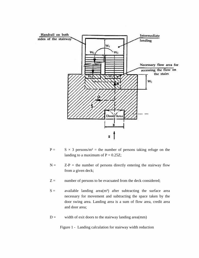
P = S × 3 persons/m² = the number of persons taking refuge on the
landing to a maximum of P = 0.25Z;
N = Z-P = the number of persons directly entering the stairway flow
from a given deck;
Z = number of persons to be evacuated from the deck considered;
S = available landing area(m²) after subtracting the surface area
necessary for movement and subtracting the space taken by the
door swing area. Landing area is a sum of flow area, credit area
and door area;
D = width of exit doors to the stairway landing area(mm)
Figure 1 - Landing calculation for stairway width reduction
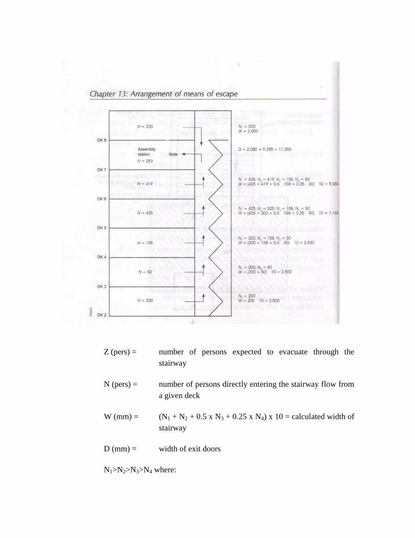
Z (pers) = number of persons expected to evacuate through the
stairway
N (pers) = number of persons directly entering the stairway flow from
a given deck
W (mm) = (N1 + N2 + 0.5 x N3 + 0.25 x N4) x 10 = calculated width of
stairway
D (mm) = width of exit doors
N1>N2>N3>N4 where:

N1 (pers) = the deck with the largest number of persons N entering
directly the stairway
N2 (pers) = the deck with the next largest number of persons N entering
directly the stairway, etc.
Note: The doors to the assembly station should have aggregate width of
11355mm.
Figure 2 - Minimum stairway width(M) calculation example
2.1.2.2.2 Distribution of persons
2.1.2.2.2.1 The dimension of the means of escape shall be calculated on the basis of the
total number of persons expected to escape by the stairway and through doorways,
corridors and landings (see figure 3). Calculations shall be made separately for the two
cases of occupancy of the spaces specified below. For each component part of the escape
route, the dimension taken shall not be less than the largest dimension determined for
each case:
Case 1: Passengers in cabins with maximum berthing capacity fully
occupied;
members of the crew in cabins occupied to 2/3 of maximum
berthing capacity; and service spaces occupied by 1/3 of the crew.
Case 2: Passengers in public spaces occupied to 3/4 of maximum capacity;
members of the crew in public spaces occupied to 1/3 of the
maximum capacity;
service spaces occupied by 1/3 of the crew; and
crew accommodation occupied by 1/3 of the crew.

Figure 3 - Occupant loading calculation example
2.1.2.2.2.2 The maximum number of persons contained in a main vertical zone, including
persons entering stairways from another main vertical zone, shall not be assumed to be
higher than the maximum number of persons authorized to be carried on board for the
calculation of stairway width only.
2.1.3 Prohibition of decrease in width in the direction to the assembly station *
*Refer to the Indication of the "assembly station" in passenger ships (MSC/Circ.777).
The stairway shall not decrease in width in the direction of evacuation to the assembly
station. Where several assembly stations are in one main vertical zone the stairway width
shall not decrease in the direction of the evacuation to the most distant assembly station.
2.2 Details of stairways
2.2.1 Handrails
Stairways shall be fitted with handrails on each side. The maximum clear width between
handrails shall be 1,800 mm.
2.2.2 Alignment of stairways
All stairways sized for more than 90 persons shall be aligned fore and aft.
2.2.3 Vertical rise and inclination
Stairways shall not exceed 3.5 m in vertical rise without the provision of a landing and
shall not have an angle of inclination greater than 45°.
2.2.4 Landings
Landings at each deck level shall be not less than 2 m² in area and shall increase by 1 m²
for every 10 persons provided for in excess of 20 persons but need not exceed 16m²,
except for those landings servicing public spaces having direct access onto the stairway
enclosure.

2.3 Doorways and corridors
2.3.1 Doorways and corridors and intermediate landings included in means of escape
shall be sized in the same manner as stairways.
2.3.2 The aggregate width of stairway exit doors to the assembly station shall not be
less than the aggregate width of stairways serving this deck.
2.4 Evacuation routes to the embarkation deck
2.4.1 Assembly station
It shall be recognized that the evacuation routes to the embarkation deck may include an
assembly station. In this case consideration shall be given to the fire-protection
requirements and sizing of corridors and doors from the stairway enclosure to the
assembly station and from the assembly station to the embarkation deck, noting that
evacuation of persons from assembly stations to embarkation positions will be carried out
in small control groups.
2.4.2 Routes from the assembly station to the survival craft embarkation position
Where the passengers and crew are held at an assembly station which is not at the
survival craft embarkation position, the dimension of stairway width and doors from the
assembly station to this position shall not (word ‘not’ has been deleted as per the
erratum published for FSS Code 2007) be based on the number of persons in the
controlled group. The width of these stairways and doors need not exceed 1,500 mm
unless larger dimensions are required for evacuation of these spaces under normal
conditions.
2.5 Means of escape plans
2.5.1 Means of escape plans shall be provided indicating the following:
.1 the number of the crew and passengers in all normally occupied spaces;
.2 the number of crew and passengers expected to escape by stairway and
through doorways, corridors and landings;
.3 assembly stations and survival craft embarkation positions;

.4 primary and secondary means of escape; and
.5 width of stairways, doors, corridors and landing areas.
2.5.2 Means of escape plans shall be accompanied by detailed calculation for
determining the width of escape stairways, doors, corridors and landing areas.
3 Cargo ships
Stairways and corridors used as means of escape shall be not less than 700 mm in clear
width and shall have a handrail on one side. Stairways and corridors with a clear width of
1,800 mm and over shall have handrails on both sides. "Clear width" is considered the
distance between the handrail and the bulkhead on the other side or between the
handrails. The angle of inclination of stairways should be, in general, 45° but not greater
than 50° and in machinery spaces and small spaces not more than 60° Doorways which
give access to a stairway shall be of the same size as the stairway.

Chapter 14 - Fixed deck foam systems
1 Application
This chapter details the specifications for fixed deck foam systems which are required to
be provided by chapter II-2 of the SOLAS Convention.
2 Engineering specifications
2.1 General
2.1.1 The arrangements for providing foam shall be capable of delivering foam to the
entire cargo tanks deck area as well as into any cargo tank the deck of which has been
ruptured.
2.1.2 The deck foam system shall be capable of simple and rapid operation.
2.1.3 Operation of a deck foam system at its required output shall permit the
simultaneous use of the minimum required number of jets of water at the required
pressure from the fire main.
2.2 Component requirements
2.2.1 Foam solution and foam concentrate
2.2.1.1 The rate of supply of foam solution shall be not less than the greatest of the
following:
.1 0.6 ℓ/min per square metre of cargo tanks deck area, where cargo tanks
deck area means the maximum breadth of the ship multiplied by the total
longitudinal extent of the cargo tank spaces;
.2 6 ℓ/min per square metre of the horizontal sectional area of the single tank
having the largest such area; or
.3 3 ℓ/min per square metre of the area protected by the largest monitor, such
area being entirely forward of the monitor, but not less than 1,250 ℓ/min.

2.2.1.2 Sufficient foam concentrate shall be supplied to ensure at least 20 min of foam
generation in tankers fitted with an inert gas installation or 30 min of foam generation in
tankers not fitted with an inert gas installation when using solution rates stipulated in
paragraph 2.2.1.1, as appropriate, whichever is the greatest. The foam expansion ratio
(i.e., the ratio of the volume of foam produced to the volume of the mixture of water and
foam-making concentrate supplied) shall not generally exceed 12 to 1. Where systems
essentially produce low expansion foam but an expansion ratio slightly in excess of 12 to
1, the quantity of foam solution available shall be calculated as for 12 to 1 expansion
ratio systems.* When medium expansion ratio foam
**(between 50 to 1 and 150 to 1
expansion ratio) is employed, the application rate of the foam and the capacity of a
monitor installation shall be to the satisfaction of the Administration.
* Refer to the Guidelines for the performance and testing criteria, and surveys of low-
expansion foam concentrates for fixed fire-extinguishing systems (MSC/Circ.582 and
Corr.1).
** Refer to the Guidelines for the performance and testing criteria, and surveys of
medium expansion foam concentrates for fixed fire-extinguishing systems (MSC/Circ.798
2.2.2 Monitors and foam applicators
2.2.2.1 Foam from the fixed foam system shall be supplied by means of monitors and
foam applicators. At least 50% of the foam solution supply rate required in paragraphs
2.2.1.1.1 and 2.2.1.1.2 shall be delivered from each monitor. On tankers of less than
4,000 tons deadweight the Administration may not require installation of monitors but
only applicators. However, in such a case the capacity of each applicator shall be at least
25% of the foam solution supply rate required in paragraphs 2.2.1.1.1 or 2.2.1.1.2.
2.2.2.2 The capacity of any monitor shall be at least 3 ℓ/min of foam solution per square
metre of deck area protected by that monitor, such area being entirely forward of the
monitor. Such capacity shall be not less than 1,250 ℓ/min.
2.2.2.3 The capacity of any applicator shall be not less than 400 ℓ/min and the applicator
throw in still air conditions shall be not less than 15 m.
2.3 Installation requirements
2.3.1 Main control station
The main control station for the system shall be suitably located outside the cargo area,
adjacent to the accommodation spaces and readily accessible and operable in the event of
fire in the areas protected.
2.3.2 Monitors
2.3.2.1 The number and position of monitors shall be such as to comply with paragraph
2.1.1.
2.3.2.2 The distance from the monitor to the farthest extremity of the protected area
forward of that monitor shall not be more than 75% of the monitor throw in still air
conditions.
2.3.2.3 A monitor and hose connection for a foam applicator shall be situated both port
and starboard at the front of the poop or accommodation spaces facing the cargo tanks
deck. On tankers of less than 4,000 tons deadweight a hose connection for a foam
applicator shall be situated both port and starboard at the front of the poop or
accommodation spaces facing the cargo tanks deck.
2.3.3 Applicators
2.3.3.1 The number of foam applicators provided shall be not less than four. The number
and disposition of foam main outlets shall be such that foam from at least two applicators
can be directed on to any part of the cargo tanks deck area.
2.3.3.2 Applicators shall be provided to ensure flexibility of action during fire-fighting
operations and to cover areas screened from the monitors.
2.3.4 Isolation valves
Valves shall be provided in the foam main, and in the fire main when this is an integral
part of the deck foam system, immediately forward of any monitor position to isolate
damaged sections of those mains.
Chapter 15 - Inert gas systems
1 Application
This chapter details the specifications for inert gas systems as required by chapter II-2 of
the SOLAS Convention.
2 Engineering specifications
2.1 General
2.1.1 Throughout this chapter the term cargo tank includes also slop tanks.
2.1.2 The inert gas system referred to in chapter II-2 of the Convention shall be
designed, constructed and tested to the satisfaction of the Administration. It shall be so
designed * and operated as to render and maintain the atmosphere of the cargo tanks non-
flammable at all times, except when such tanks are required to be gas-free. In the event
that the inert gas system is unable to meet the operational requirement set out above and
it has been assessed that it is impracticable to effect a repair, then cargo discharge,
deballasting and necessary tank cleaning shall only be resumed when the "emergency
conditions" specified in the Guidelines on Inert Gas Systems are complied with .**
* Refer to the Revised standards for the design, testing and locating of devices to
prevent the passage of flame into cargo tanks in tankers (MSC/Circ.677, as amended by
MSC/Circ.1009) and the Revised factors to be taking into consideration when designing
cargo tank venting and gas-freeing arrangements (MSC/Circ. 731)
** Refer to the Clarification of inert gas system requirements under the Convention
(MSC/ Circ.485) and to the Revised guidelines for inert gas systems (MSC/ Circ.353, as
amended by MSC/Circ.387).
2.1.3 Required functions
The system shall be capable of:
.1 inerting empty cargo tanks by reducing the oxygen content of the
atmosphere in each tank to a level at which combustion cannot be
supported;
.2 maintaining the atmosphere in any part of any cargo tank with an oxygen
content not exceeding 8% by volume and at a positive pressure at all times
in port and at sea except when it is necessary for such a tank to be gas-
free;
.3 eliminating the need for air to enter a tank during normal operations
except when it is necessary for such a tank to be gas-free; and
.4 purging empty cargo tanks of a hydrocarbon gas, so that subsequent gas-
freeing operations will at no time create a flammable atmosphere within
the tank.
2.2 Component requirements
2.2.1 Supply of inert gas
2.2.1.1 The inert gas supply may be treated flue gas from main or auxiliary boilers. The
Administration may accept systems using flue gases from one or more separate gas
generators or other sources or any combination thereof, provided that an equivalent
standard of safety is achieved. Such systems shall, as far as practicable, comply with the
requirements of this chapter. Systems using stored carbon dioxide shall not be permitted
unless the Administration is satisfied that the risk of ignition from generation of static
electricity by the system itself is minimized.
2.2.1.2 The system shall be capable of delivering inert gas to the cargo tanks at a rate of
at least 125% of the maximum rate of discharge capacity of the ship expressed as a
volume.
2.2.1.3 The system shall be capable of delivering inert gas with an oxygen content of not
more than 5 % by volume in the inert gas supply main to the cargo tanks at any required
rate of flow.
2.2.1.4 Two fuel oil pumps shall be fitted to the inert gas generator. The Administration
may permit only one fuel oil pump on condition that sufficient spares for the fuel oil
pump and its prime mover are carried on board to enable any failure of the fuel oil pump
and its prime mover to be rectified by the ship's crew.
2.2.2 Scrubbers
2.2.2.1 A flue gas scrubber shall be fitted which will effectively cool the volume of gas
specified in paragraphs 2.2.1.2 and 2.2.1.3 and remove solids and sulphur combustion
products. The cooling water arrangements shall be such that an adequate supply of water
will always be available without interfering with any essential services on the ship.
Provision shall also be made for an alternative supply of cooling water.
2.2.2.2 Filters or equivalent devices shall be fitted to minimize the amount of water
carried over to the inert gas blowers.
2.2.2.3 The scrubber shall be located aft of all cargo tanks, cargo pump-rooms and
cofferdams separating these spaces from machinery spaces of category A.
2.2.3 Blowers
2.2.3.1 At least two blowers shall be fitted and be capable of delivering to the cargo
tanks at least the volume of gas required by paragraphs 2.2.1.2 and 2.2.1.3. For systems
with gas generators the Administration may permit only one blower if that system is
capable of delivering the total volume of gas required by paragraphs 2.2.1.2 and 2.2.1.3
to the protected cargo tanks, provided that sufficient spares for the blower and its prime
mover are carried on board to enable any failure of the blower and its prime mover to be
rectified by the ship's crew.
2.2.3.2 The inert gas system shall be so designed that the maximum pressure which it
can exert on any cargo tank will not exceed the test pressure of any cargo tank. Suitable
shutoff arrangements shall be provided on the suction and discharge connections of each
blower. Arrangements shall be provided to enable the functioning of the inert gas plant to
be stabilized before commencing cargo discharge. If the blowers are to be used for gas-
freeing, their air inlets shall be provided with blanking arrangements.
2.2.3.3 The blowers shall be located aft of all cargo tanks, cargo pump-rooms and
cofferdams separating these spaces from machinery spaces of category A.

2.2.4 Water seals
2.2.4.1 The water seal referred to in paragraph 2.3.1.4.1 shall be capable of being
supplied by two separate pumps, each of which shall be capable of maintaining an
adequate supply at all times.
2.2.4.2 The arrangement of the seal and its associated fittings shall be such that it will
prevent backflow of hydrocarbon vapours and will ensure the proper functioning of the
seal under operating conditions.
2.2.4.3 Provision shall be made to ensure that the water seal is protected against freezing,
in such a way that the integrity of seal is not impaired by overheating.
2.2.4.4 A water loop or other approved arrangement shall also be fitted to each
associated water supply and drain pipe and each venting or pressure-sensing pipe leading
to gas-safe spaces. Means shall be provided to prevent such loops from being emptied by
vacuum.
2.2.4.5 The deck water seal and loop arrangements shall be capable of preventing return
of hydrocarbon vapours at a pressure equal to the test pressure of the cargo tanks.
2.2.4.6 In respect of paragraph 2.4.3.1.7, the Administration shall be satisfied as to the
maintenance of an adequate reserve of water at all times and the integrity of the
arrangements to permit the automatic formation of the water seal when the gas flow
ceases. The audible and visual alarm on the low level of water in the water seal shall
operate when the inert gas is not being supplied.
2.3 Installation requirements
2.3.1 Safety measures in the system
2.3.1.1 Flue gas isolating valves
Flue gas isolating valves shall be fitted in the inert gas supply mains between the boiler
uptakes and the flue gas scrubber. These valves shall be provided with indicators to show
whether they are open or shut, and precautions shall be taken to maintain them gas-tight
and keep the seatings clear of soot. Arrangements shall be made to ensure that boiler soot
blowers cannot be operated when the corresponding flue gas valve is open.

2.3.1.2 Prevention of flue gas leakage
2.3.1.2.1 Special consideration shall be given to the design and location of scrubber and
blowers with relevant piping and fittings in order to prevent flue gas leakages into
enclosed spaces.
2.3.1.2.2 To permit safe maintenance, an additional water seal or other effective means of
preventing flue gas leakage shall be fitted between the flue gas isolating valves and
scrubber or incorporated in the gas entry to the scrubber.
2.3.1.3 Gas regulating valves
2.3.1.3.1 A gas regulating valve shall be fitted in the inert gas supply main. This valve
shall be automatically controlled to close as required in paragraphs 2.3.1.5. It shall also
be capable of automatically regulating the flow of inert gas to the cargo tanks unless
means are provided to automatically control the speed of the inert gas blowers required in
paragraph 2.2.3.
2.3.1.3.2 The valve referred to in paragraph 2.3.1.3.1 shall be located at the forward
bulkhead of the forward most gas-safe space *
through which the inert gas supply main
passes.
* A gas-safe space is a space in which the entry of hydrocarbon gases would produce
hazards with regard to flammability or toxicity.
2.3.1.4 Non-return devices of flue gas
2.3.1.4.1 At least two non-return devices, one of which shall be a water seal, shall be
fitted in the inert gas supply main, in order to prevent the return of hydrocarbon vapour to
the machinery space uptakes or to any gas-safe spaces under all normal conditions of
trim, list and motion of the ship. They shall be located between the automatic valve
required by paragraph 2.3.1.3.1 and the aftermost connection to any cargo tank or cargo
pipeline.
2.3.1.4.2 The devices referred to in paragraph 2.3.1.4.1 shall be located in the cargo area
on deck.
2.3.1.4.3 The second device shall be a non-return valve or equivalent capable of
preventing the return of vapours or liquids and fitted forward of the deck water seal
required in paragraph 2.3.1.4.1. It shall be provided with positive means of closure. As an

alternative to positive means of closure, an additional valve having such means of closure
may be provided forward of the non-return valve to isolate the deck water seal from the
inert gas main to the cargo tanks.
2.3.1.4.4 As an additional safeguard against the possible leakage of hydrocarbon liquids
or vapours back from the deck main, means shall be provided to permit this section of the
line between the valve having positive means of closure referred to in paragraph 2.3.1.4.3
and the valve referred to in paragraph 2.3.1.3 to be vented in a safe manner when the first
of these valves is closed.
2.3.1.5 Automatic shutdown
2.3.1.5.1 Automatic shutdown of the inert gas blowers and gas regulating valve shall be
arranged on predetermined limits being reached in respect of paragraphs 2.4.3.1.1,
2.4.3.1.2 and 2.4.3.1.3.
2.3.1.5.2 Automatic shutdown of the gas regulating valve shall be arranged in respect of
paragraph 2.4.3.1.4.
2.3.1.6 Oxygen rich gas
In respect of paragraph 2.4.3.1.5, when the oxygen content of the inert gas exceeds 8% by
volume, immediate action shall be taken to improve the gas quality. Unless the quality of
the gas improves, all cargo tank operations shall be suspended so as to avoid air being
drawn into the tanks and the isolation valve referred to in paragraph 2.3.1.4.3 shall be
closed.
2.3.2 Inert gas lines
2.3.2.1 The inert gas main may be divided into two or more branches forward of the non-
return devices required by paragraphs 2.2.4 and 2.3.1.4.
2.3.2.2 The inert gas supply main shall be fitted with branch piping leading to each cargo
tank. Branch piping for inert gas shall be fitted with either stop valves or equivalent
means of control for isolating each tank. Where stop valves are fitted, they shall be
provided with locking arrangements, which shall be under the control of a responsible
ship's officer. The control system shall provide unambiguous information of the
operational status of such valves.
2.3.2.3 In combination carriers, the arrangement to isolate the slop tanks containing oil
or oil residues from other tanks shall consist of blank flanges which will remain in
position at all times when cargoes other than oil are being carried except as provided for
in the relevant section of the Guidelines on Inert Gas Systems.*
* Refer to the Revised guidelines for inert-gas system (MSC/Circ.353), as amended by
MSC/Circ.387.
2.3.2.4 Means shall be provided to protect cargo tanks against the effect of overpressure
or vacuum caused by thermal variations when the cargo tanks are isolated from the inert
gas mains.
2.3.2.5 Piping systems shall be so designed as to prevent the accumulation of cargo or
water in the pipelines under all normal conditions.
2.3.2.6 Arrangements shall be provided to enable the inert gas main to be connected to
an external supply of inert gas. The arrangements shall consist of a 250 mm nominal pipe
size bolted flange, isolated from the inert gas main by a valve and located forward of the
non-return valve referred to in paragraph 2.3.1.4.3. The design of the flange should
conform to the appropriate class in the standards adopted for the design of other external
connections in the ship's cargo piping system.
2.3.2.7 If a connection is fitted between the inert gas supply main and the cargo piping
system, arrangements shall be made to ensure an effective isolation having regard to the
large pressure difference which may exist between the systems. This shall consist of two
shutoff valves with an arrangement to vent the space between the valves in a safe manner
or an arrangement consisting of a spool-piece with associated blanks.
2.3.2.8 The valve separating the inert gas supply main from the cargo main and which is
on the cargo main side shall be a non-return valve with a positive means of closure.
2.4 Operation and control requirements
2.4.1 Indication devices
Means shall be provided for continuously indicating the temperature and pressure of the
inert gas at the discharge side of the gas blowers, whenever the gas blowers are operating.
2.4.2 Indicating and recording devices

2.4.2.1 Instrumentation shall be fitted for continuously indicating and permanently
recording, when inert gas is being supplied:
.1 the pressure of the inert gas supply mains forward of the non-return
devices required by paragraph 2.3.1.4.1; and
.2 the oxygen content of the inert gas in the inert gas supply mains on the
discharge side of the gas blowers.
2.4.2.2 The devices referred to in paragraph 2.4.2.1 shall be placed in the cargo control
room where provided. But where no cargo control room is provided, they shall be placed
in a position easily accessible to the officer in charge of cargo operations.
2.4.2.3 In addition, meters shall be fitted:
.1 in the navigation bridge to indicate at all times the pressure referred to in
paragraph 2.4.2.1.1 and the pressure in the slop tanks of combination
carriers, whenever those tanks are isolated from the inert gas supply main;
and
.2 in the machinery control room or in the machinery space to indicate the
oxygen content referred to in paragraph 2.4.2.1.2.
2.4.2.4 Portable instruments for measuring oxygen and flammable vapour concentration
shall be provided. In addition, suitable arrangement shall be made on each cargo tank
such that the condition of the tank atmosphere can be determined using these portable
instruments.
2.4.2.5 Suitable means shall be provided for the zero and span calibration of both fixed
and portable gas concentration measurement instruments, referred to in paragraphs
2.4.2.1 to 2.4.2.4
2.4.3 Audible and visual alarms
2.4.3.1 For inert gas systems of both the flue gas type and the inert gas generator type,
audible and visual alarms shall be provided to indicate:
.1 low water pressure or low water flow rate to the flue gas scrubber as
referred to in paragraph 2.2.2.1;

.2 high water level in the flue gas scrubber as referred to in paragraph
2.2.2.1;
.3 high gas temperature as referred to in paragraph 2.4.1;
.4 failure of the inert gas blowers referred to in paragraph 2.2.3;
.5 oxygen content in excess of 8% by volume as referred to in paragraph
2.4.2.1.2;
.6 failure of the power supply to the automatic control system for the gas
regulating valve and to the indicating devices as referred to in paragraphs
2.3.1.3 and 2.4.2.1;
.7 low water level in the water seal as referred to in paragraph 2.3.1.4.1;
.8 gas pressure less than 100 mm water gauge as referred to in paragraph
2.4.2.1.1. The alarm arrangement shall be such as to ensure that the
pressure in slop tanks in combination carriers can be monitored at all
times; and
.9 high gas pressure as referred to in paragraph 2.4.2.1.1.
2.4.3.2 For inert gas systems of the inert gas generator type, additional audible and visual
alarms shall be provided to indicate:
.1 insufficient fuel oil supply;
.2 failure of the power supply to the generator; and
.3 failure of the power supply to the automatic control system for the
generator.
2.4.3.3 The alarms required in paragraphs 2.4.3.1.5, 2.4.3.1.6 and 2.4.3.1.8 shall be fitted
in the machinery space and cargo control room, where provided, but in each case in such
a position that they are immediately received by responsible members of the crew.
2.4.3.4 An audible alarm system independent of that required in paragraph 2.4.3.1.8 or
automatic shutdown of cargo pumps shall be provided to operate on predetermined limits
of low pressure in the inert gas main being reached.
2.4.4 Instruction manuals
Detailed instruction manuals shall be provided on board, covering the operations, safety
and maintenance requirements and occupational health hazards relevant to the inert gas
system and its application to the cargo tank system.* The manuals shall include guidance
on procedures to be followed in the event of a fault or failure of the inert gas system.
* Refer to the Revised guidelines for inert-gas system (MSC/Circ.353), as amended by
MSC/Circ.387.

Chapter 16 - Fixed hydrocarbon gas detection systems
1 Application
1.1 This chapter details the specifications for fixed hydrocarbon gas detection systems
as required by chapter II-2 of the Convention.
1.2 A combined gas detection system required by regulations II-2/4.5.7.3 and II-
2/4.5.10 may be accepted in cases where the system fully complies with the requirement
of regulation II-2/2 of the Convention.
(Amended by Res.MSC.292(87))
2 Engineering specifications
2.1 General
2.1.1 The fixed hydrocarbon gas detection system referred to in chapter II-2 of the
Convention shall be designed, constructed and tested to the satisfaction of the
Administration based on performance standards developed by the Organization.*
* Refer to the Guidelines for the design, construction and testing of fixed hydrocarbon
gas detection system (MSC.1/Circ.1370).
2.1.2 The system shall be comprised of a central unit for gas measurement and analysis
and gas sampling pipes in all ballast tanks and void spaces of double-hull and double-
bottom spaces adjacent to the cargo tanks, including the forepeak tank and any other
tanks and spaces under the bulkhead deck adjacent to cargo tanks.
2.1.3 The system may be integrated with the cargo pump-room gas detection system,
provided that the spaces referred to in paragraph 2.1.2 are sampled at the rate required in
paragraph 2.2.3.1. Continuous sampling from other locations may also be considered
provided the sampling rate is complied with.
(Amended by Res.MSC.292(87))

2.2 Component requirements
2.2.1 Gas sampling lines
2.2.1.1 Common sampling lines to the detection equipment shall not be fitted, except the
lines serving each pair of sampling points as required in paragraph 2.2.1.3.
2.2.1.2 The materials of construction and the dimensions of gas sampling lines shall be
such as to prevent restriction. Where non-metallic materials are used, they shall be
electrically conductive. The gas sampling lines shall not be made of aluminium.
2.2.1.3 The configuration of gas sampling lines shall be adapted to the design and size of
each space. Except as provided in paragraphs 2.2.1.4 and 2.2.1.5, the sampling system
shall allow for a minimum of two hydrocarbon gas sampling points, one located on the
lower and one on the upper part where sampling is required. When required, the upper
gas sampling point shall not be located lower than 1 m from the tank top. The position of
the lower located gas sampling point shall be above the height of the girder of bottom
shell plating but at least 0.5 m from the bottom of the tank and it shall be provided with
means to be closed when clogged. In positioning the fixed sampling points, due regard
should also be given to the density of vapours of the oil products intended to be
transported and the dilution from space purging or ventilation.
2.2.1.4 For ships with deadweight of less than 50,000 tonnes, the Administration may
allow the installation of one sampling location for each tank for practical and/or
operational reasons.
2.2.1.5 For ballast tanks in the double-bottom, ballast tanks not intended to be partially
filled and void spaces, the upper gas sampling point is not required.
2.2.1.6 Means shall be provided to prevent gas sampling lines from clogging when tanks
are ballasted by using compressed air flushing to clean the line after switching from
ballast to cargo loaded mode. The system shall have an alarm to indicate if the gas
sampling lines are clogged.
2.2.2 Gas analysis unit
2.2.2.1 The gas analysis unit shall be located in a safe space and may be located in areas
outside the ship's cargo area; for example, in the cargo control room and/or navigation
bridge in addition to the hydraulic room when mounted on the forward bulkhead,
provided the following requirements are observed:

.1 sampling lines shall not run through gas safe spaces, except where
permitted under subparagraph .5;
.2 the hydrocarbon gas sampling pipes shall be equipped with flame
arresters. Sample hydrocarbon gas is to be led to the atmosphere with
outlets arranged in a safe location, not close to a source of ignitions and
not close to the accommodation area air intakes;
.3 a manual isolating valve, which shall be easily accessible for operation
and maintenance, shall be fitted in each of the sampling lines at the
bulkhead on the gas safe side;
.4 the hydrocarbon gas detection equipment including sample piping, sample
pumps, solenoids, analysing units etc., shall be located in a reasonably
gas-tight cabinet (e.g., fully enclosed steel cabinet with a door with
gaskets) which is to be monitored by its own sampling point. At a gas
concentration above 30% of the lower flammable limit inside the steel
enclosure the entire gas analysing unit is to be automatically shut down;
and
.5 where the enclosure cannot be arranged directly on the bulkhead, sample
pipes shall be of steel or other equivalent material and without detachable
connections, except for the connection points for isolating valves at the
bulkhead and analysing unit, and are to be routed on their shortest ways.
2.2.3 Gas detection equipment
2.2.3.1 The gas detection equipment shall be designed to sample and analyse from each
sampling line of each protected space, sequentially at intervals not exceeding 30 min.
2.2.3.2 Means shall be provided to enable measurements with portable instruments, in
case the fixed system is out of order or for system calibration. In case the system is out of
order, procedures shall be in place to continue to monitor the atmosphere with portable
instruments and to record the measurement results.
2.2.3.3 Audible and visual alarms are to be initiated in the cargo control room,
navigation bridge and at the analysing unit when the vapour concentration in a given
space reaches a pre-set value, which shall not be higher than the equivalent of 30% of the
lower flammable limit.

2.2.3.4 The gas detection equipment shall be so designed that it may readily be tested
and calibrated.
(Amended by Res.MSC.292(87))


P:\DOCS\A 800.DOC
A 19/Res.800 14 December 1995 Original: ENGLISH ASSEMBLY 19th session Agenda item 10
RESOLUTION A.800(19) adopted on 23 November 1995
REVISED GUIDELINES FOR APPROVAL OF SPRINKLER SYSTEMS
EQUIVALENT TO THAT REFERRED TO IN SOLAS REGULATION II-2/12
THE ASSEMBLY,
RECALLING Article 15(j) of the Convention on the International Maritime Organization concerning the functions of the Assembly in relation to regulations and guidelines concerning maritime safety,
NOTING the significance of the performance and reliability of the sprinkler systems approved under the provisions of regulation II-2/12 of the International Convention for the Safety of Life at Sea (SOLAS), 1974,
DESIROUS of keeping abreast of the advancement of sprinkler technology and further improving fire protection on board ships,
HAVING CONSIDERED the recommendation made by the Maritime Safety Committee at its sixty-fourth session, 1. ADOPTS the Revised Guidelines for Approval of Sprinkler Systems Equivalent to that referred to in SOLAS regulation II-2/12 set out in the Annex to the present resolution; 2. INVITES Governments to apply the Guidelines when approving equivalent sprinkler systems; 3. REQUESTS the Maritime Safety Committee to keep the Guidelines under review and to amend them as necessary; 4. REVOKES resolution A.755(18).

A 19/Res.800 - 2 -
P:\DOCS\A 800.DOC
ANNEX REVISED GUIDELINES FOR APPROVAL OF SPRINKLER SYSTEMS EQUIVALENT TO THAT REFERRED TO IN SOLAS REGULATION II-2/12 1 General
Equivalent sprinkler systems must have the same characteristics which have been identified as significant to the performance and reliability of automatic sprinkler systems approved under the requirements of SOLAS regulation II-2/12. 2 Definitions 2.1 Antifreeze system: A wet pipe sprinkler system employing automatic sprinklers attached to a piping system containing an antifreeze solution and connected to a water supply. The antifreeze solution is discharged, followed by water, immediately upon operation of sprinklers opened by heat from a fire. 2.2 Deluge system: A sprinkler system employing open sprinklers attached to a piping system connected to a water supply through a valve that is opened by the operation of a detection system installed in the same areas as the sprinklers. When this valve opens, water flows into the piping system and discharges from all sprinklers attached thereto. 2.3 Dry pipe system: A sprinkler system employing automatic sprinklers attached to a piping system containing air or nitrogen under pressure, the release of which (as from the opening of a sprinkler) permits the water pressure to open a valve known as a dry pipe valve. The water then flows into the piping system and out of the opened sprinklers. 2.4 Preaction system: A sprinkler system employing automatic sprinklers attached to a piping system containing air that may or may not be under pressure, with a supplemental detection system installed in the same area as the sprinklers. Actuation of the detection system opens a valve that permits water to flow into the sprinkler piping system and to be discharged from any sprinklers that may be open. 2.5 Water-based extinguishing medium: Fresh water or sea water with or without additives mixed to enhance fire-extinguishing capability. 2.6 Wet pipe system: A sprinkler system employing automatic sprinklers attached to a piping system containing water and connected to a water supply so that water discharges immediately from sprinklers opened by heat from a fire. 3 Principal requirements for the system 3.1 The system should be automatic in operation, with no human action necessary to set it in operation. 3.2 The system should be capable of both detecting the fire and acting to control or suppress the fire with a water-based extinguishing medium. 3.3 The sprinkler system should be capable of continuously supplying the water-based extinguishing medium for a minimum of 30 min. A pressure tank should be provided to meet the functional requirement stipulated in SOLAS regulation II-2/12.4.1.

- 3 - A 19/Res.800
P:\DOCS\A 800.DOC
3.4 The system should be of the wet pipe type but small exposed sections may be of the dry pipe, preaction, deluge, antifreeze or other type to the satisfaction of the Administration where this is necessary. 3.5 The system should be capable of fire control or suppression under a wide variety of fire loading, fuel arrangement, room geometry and ventilation conditions. 3.6 The system and equipment should be suitably designed to withstand ambient temperature changes, vibration, humidity, shock, impact, clogging and corrosion normally encountered in ships. 3.7 The system and its components should be designed and installed in accordance with international standards acceptable to the Organization*, and manufactured and tested to the satisfaction of the Administration in accordance with the requirements given in appendices 1 and 2 to these guidelines. 3.8 The system should be provided with both main and emergency sources of power. 3.9 The system should be provided with a redundant means of pumping or otherwise supplying a water-based extinguishing medium to the sprinkler system. 3.10 The system should be fitted with a permanent sea inlet and be capable of continuous operation using seawater. 3.11 The piping system should be sized in accordance with an hydraulic calculation technique.** 3.12 Sprinklers should be grouped into separate sections. Any section should not serve more than two decks of one main vertical zone. 3.13 Each section of sprinklers should be capable of being isolated by one stop valve only. The stop valve in each section should be readily accessible and its location should be clearly and permanently indicated. Means should be provided for preventing the stop valves being operated by an unauthorized person.
*Pending the development of international standards acceptable to the Organization, national standards as prescribed by the Administration should be applied.
**Where the Hazen-Williams Method is used, the following values of the friction factor "C" for different pipe types which may be considered should apply:
Pipe type C
Black or galvanized mild steel 120 Copper and copper alloys 150 Stainless steel 150 Plastic 150
3.14 Sprinkler piping should not be used for any other purpose. 3.15 The sprinkler system supply components should be outside category A machinery spaces. 3.16 A means for testing the automatic operation of the system for assuring the required pressure and flow should be provided. 3.17 Each sprinkler section should be provided with a means for giving a visual and audible alarm at a
A 19/Res.800 - 4 -
P:\DOCS\A 800.DOC
continuously manned central control station within one minute of flow from one or more sprinklers, a check valve, pressure gauge, and a test connection with a means of drainage. 3.18 A sprinkler control plan should be displayed at each centrally manned control station. 3.19 Installation plans and operating manuals should be supplied to the ship and be readily available on board. A list or plan should be displayed showing the spaces covered and the location of the zone in respect of each section. Instructions for testing and maintenance should also be available on board. 3.20 Sprinklers should have fast response characteristics as defined in ISO standard 6182-1. 3.21 In accommodation and service spaces the sprinklers should have a nominal temperature rating of 57°C to 79°C, except that in locations such as drying rooms, where high ambient temperatures might be expected, the nominal temperature may be increased by not more than 30°C above the maximum deckhead temperature. 3.22 Pumps and alternative supply components should be sized so as to be capable of maintaining the required flow to the hydraulically most demanding area of not less than 280 m2. For application to a small ship with a total protected area of less than 280 m2, the Administration may specify the appropriate area for sizing of pumps and alternative supply components.

- 5 - A 19/Res.800
P:\DOCS\A 800.DOC
APPENDIX 1 COMPONENT MANUFACTURING STANDARDS FOR WATER MIST NOZZLES TABLE OF CONTENTS 1 Introduction 2 Definitions 3 Product consistency 4 Water mist nozzle requirements 4.1 Dimensions 4.2 Nominal release temperatures 4.3 Operating temperatures 4.4 Water flow and distribution 4.5 Function 4.6 Strength of body 4.7 Strength of release element 4.8 Leak resistance and hydrostatic strength 4.9 Heat exposure 4.10 Thermal shock 4.11 Corrosion 4.12 Integrity of nozzle coatings 4.13 Water hammer 4.14 Dynamic heating 4.15 Resistance to heat 4.16 Resistance to vibration 4.17 Impact test 4.18 Lateral discharge 4.19 30-day leakage resistance 4.20 Vacuum resistance 4.21 Water shield 4.22 Clogging 5 Methods of test 5.1 General 5.2 Visual examination 5.3 Body strength test 5.4 Leak resistance and hydrostatic strength tests 5.5 Functional test 5.6 Heat responsive element operating characteristics 5.6.1 Operating temperature test 5.6.2 Dynamic heating tests 5.7 Heat exposure tests 5.8 Thermal shock test for glass bulb nozzles 5.9 Strength tests for release elements TABLE OF CONTENTS (continued)
A 19/Res.800 - 6 -
P:\DOCS\A 800.DOC
5.10 Water flow test 5.11 Water distribution and droplet size tests 5.12 Corrosion tests 5.12.1 Stress corrosion test for brass nozzle parts 5.12.2 Stress corrosion cracking of stainless steel nozzle parts 5.12.3 Sulphur dioxide corrosion test 5.12.4 Salt spray corrosion test 5.12.5 Moist air exposure test 5.13 Nozzle coating tests 5.14 Heat resistance test 5.15 Water hammer test 5.16 Vibration test 5.17 Impact test 5.18 Lateral discharge test 5.19 30-day leakage test 5.20 Vacuum test 5.21 Clogging test 6 Water mist nozzle markings 6.1 General 6.2 Nozzle housings Figure 1 RTI and C limits for standard orientation Figure 2 Impact test apparatus Figure 3 Clogging test apparatus Table 1 Nominal release temperature Table 2 Plunge oven test conditions Table 3 Plunge oven test conditions for conductivity determinations Table 4 Test temperatures for coated and uncoated nozzles Table 5 Contaminant for contaminated water cycling test

- 7 - A 19/Res.800
P:\DOCS\A 800.DOC
1 INTRODUCTION 1.1 This document is intended to address minimum fire protection performance, construction and marking requirements, excluding fire performance, for water mist nozzles. 1.2 Numbers in brackets following a section or subsection heading refer to the appropriate section or paragraph in the standard for automatic sprinkler systems (part 1: Requirements and methods of test for sprinklers, ISO 6182-1). 2 DEFINITIONS 2.1 Conductivity factor (C): a measure of the conductance between the nozzle's heat responsive element and the fitting expressed in units of (m/s)0.5. 2.2 Rated working pressure: maximum service pressure at which a hydraulic device is intended to operate. 2.3 Response time index (RTI): a measure of nozzle sensitivity expressed as RTI = tu0.5, where t is the time constant of the heat responsive element in units of seconds, and u is the gas velocity expressed in metres per second. RTI can be used in combination with the conductivity factor (C) to predict the response of a nozzle in fire environments defined in terms of gas temperature and velocity versus time. RTI has units of (m⋅s)0.5. 2.4 Standard orientation: in the case of nozzles with symmetrical heat responsive elements supported by frame arms, standard orientation is with the air flow perpendicular to both the axis of the nozzle's inlet and the plane of the frame arms. In the case of non-symmetrical heat responsive elements, standard orientation is with the air flow perpendicular to both the inlet axis and the plane of the frame arms which produces the shortest response time. 2.5 Worst case orientation: the orientation which produces the longest response time with the axis of the nozzle inlet perpendicular to the air flow. 3 PRODUCT CONSISTENCY 3.1 It should be the responsibility of the manufacturer to implement a quality control programme to ensure that production continuously meets the requirements in the same manner as the originally tested samples. 3.2 The load on the heat responsive element in automatic nozzles should be set and secured by the manufacturer in such a manner so as to prevent field adjustment or replacement. 4 WATER MIST NOZZLE REQUIREMENTS 4.1 Dimensions
Nozzles should be provided with a nominal 6 mm (1/4 in.) or larger nominal inlet thread or equivalent. The dimensions of all threaded connections should conform to international standards where applied. National standards may be used if international standards are not applicable. 4.2 Nominal release temperatures [6.2]*
*Figures given in square brackets refer to ISO standard 6182-1.
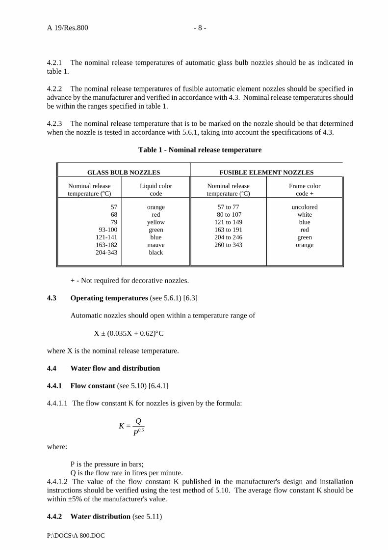
A 19/Res.800 - 8 -
P:\DOCS\A 800.DOC
4.2.1 The nominal release temperatures of automatic glass bulb nozzles should be as indicated in table 1. 4.2.2 The nominal release temperatures of fusible automatic element nozzles should be specified in advance by the manufacturer and verified in accordance with 4.3. Nominal release temperatures should be within the ranges specified in table 1. 4.2.3 The nominal release temperature that is to be marked on the nozzle should be that determined when the nozzle is tested in accordance with 5.6.1, taking into account the specifications of 4.3.
Table 1 - Nominal release temperature
GLASS BULB NOZZLES
FUSIBLE ELEMENT NOZZLES
Nominal release temperature (ºC)
Liquid color
code
Nominal release temperature (ºC)
Frame color
code +
57 68 79
93-100 121-141 163-182 204-343
orange
red yellow green blue
mauve black
57 to 77
80 to 107 121 to 149 163 to 191 204 to 246 260 to 343
uncolored
white blue red
green orange
+ - Not required for decorative nozzles.
4.3 Operating temperatures (see 5.6.1) [6.3]
Automatic nozzles should open within a temperature range of
X ± (0.035X + 0.62)°C where X is the nominal release temperature. 4.4 Water flow and distribution 4.4.1 Flow constant (see 5.10) [6.4.1] 4.4.1.1 The flow constant K for nozzles is given by the formula: where:
P is the pressure in bars; Q is the flow rate in litres per minute.
4.4.1.2 The value of the flow constant K published in the manufacturer's design and installation instructions should be verified using the test method of 5.10. The average flow constant K should be within ±5% of the manufacturer's value. 4.4.2 Water distribution (see 5.11)
PQ = K
0.5

- 9 - A 19/Res.800
P:\DOCS\A 800.DOC
Nozzles which have complied with the requirements of the fire test should be used to determine
the effective nozzle discharge characteristics when tested in accordance with 5.11.1. These characteristics should be published in the manufacturer's design and installation instructions. 4.4.3 Water droplet size and velocity (see 5.11.2)
The water droplet size distribution and droplet velocity distribution should be determined in accordance with 5.11.2 for each design nozzle at the minimum and maximum operating pressures, and minimum and maximum air flow rates, when used, as part of the identification of the discharge characteristics of the nozzles which have demonstrated compliance with the fire test. The measurements should be made at two representative locations:
.1 perpendicular to the central axis of the nozzle, exactly 1 m below the discharge orifice or discharge deflector; and
.2 radially outward from the first location at either 0.5 m or 1 m distance, depending on the
distribution pattern. 4.5 Function (see 5.5) [6.5] 4.5.1 When tested in accordance with 5.5, the nozzle should open and, within 5 s after the release of the heat responsive element, should operate satisfactorily by complying with the requirements of 5.10. Any lodgement of released parts should be cleared within 60 s of release for standard response heat responsive elements and within 10 s of release for fast and special response heat responsive elements or the nozzle should then comply with the requirements of 5.11. 4.5.2 The nozzle discharge components should not sustain significant damage as a result of the functional test specified in 5.5 and should have the same flow constant range and water droplet size and velocity within 5% of values as previously determined in accordance with 4.4.1 and 4.4.3. 4.6 Strength of body (see 5.3) [6.6]
The nozzle body should not show permanent elongation of more than 0.2% between the load-bearing points after being subjected to twice the average service load as determined using the method of 5.3.1. 4.7 Strength of release element [6.7] 4.7.1 Glass bulbs (see 5.9.1)
The lower tolerance limit for bulb strength should be greater than two times the upper tolerance limit for the bulb design load based on calculations with a degree of confidence of 0.99 for 99% of the samples as determined in 5.9.1. Calculations will be based on the normal or gaussian distribution except where another distribution can be shown to be more applicable due to manufacturing or design factors. 4.7.2 Fusible elements (see 5.9.2)
Fusible heat-responsive elements in the ordinary temperature range should be designed to:
.1 sustain a load of 15 times its design load corresponding to the maximum service load measured in 5.3.1 for a period of 100 h; or
A 19/Res.800 - 10 -
P:\DOCS\A 800.DOC
.2 demonstrate the ability to sustain the design load. 4.8 Leak resistance and hydrostatic strength (see 5.4) [6.8] 4.8.1 A nozzle should not show any sign of leakage when tested by the method specified in 5.4.1. 4.8.2 A nozzle should not rupture, operate or release any parts when tested by the method specified in 5.4.2. 4.9 Heat exposure [6.9] 4.9.1 Glass bulb nozzles (see 5.7.1)
There should be no damage to the glass bulb element when the nozzle is tested by the method specified in 5.7.1. 4.9.2 All uncoated nozzles (see 5.7.2)
Nozzles should withstand exposure to increased ambient temperature without evidence of weakness or failure, when tested by the method specified in 5.7.2. 4.9.3 Coated nozzles (see 5.7.3)
In addition to meeting the requirement of 5.7.2 in an uncoated version, coated nozzles should withstand exposure to ambient temperatures without evidence of weakness or failure of the coating, when tested by the method specified in 5.7.3. 4.10 Thermal shock (see 5.8) [6.10]
Glass bulb nozzles should not be damaged when tested by the method specified in 5.8. Proper operation is not considered as damage. 4.11 Corrosion [6.11] 4.11.1 Stress corrosion (see 5.12.1 and 5.12.2)
When tested in accordance with 5.12.1, all brass nozzles should show no fractures which could affect their ability to function as intended and satisfy other requirements. When tested in accordance with 5.12.2, stainless steel parts of water mist nozzles should show no fractures or breakage which could affect their ability to function as intended and satisfy other requirements. 4.11.2 Sulphur dioxide corrosion (see 5.12.3)
Nozzles should be sufficiently resistant to sulphur dioxide saturated with water vapour when conditioned in accordance with 5.12.3. Following exposure, five nozzles should operate when functionally tested at their minimum flowing pressure (see 4.5.1 and 4.5.2). The remaining five samples should meet the dynamic heating requirements of 4.14.2. 4.11.3 Salt spray corrosion (see 5.12.4)
- 11 - A 19/Res.800
P:\DOCS\A 800.DOC
Coated and uncoated nozzles should be resistant to salt spray when conditioned in accordance with 5.12.4. Following exposure, the samples should meet the dynamic heating requirements of 4.14.2. 4.11.4 Moist air exposure (see 5.12.5)
Nozzles should be sufficiently resistant to moist air exposure and should satisfy the requirements of 4.14.2 after being tested in accordance with 5.12.5. 4.12 Integrity of nozzle coatings [6.12] 4.12.1 Evaporation of wax and bitumen used for atmospheric protection of nozzles (see 5.13.1)
Waxes and bitumens used for coating nozzles should not contain volatile matters in sufficient quantities to cause shrinkage, hardening, cracking or flaking of the applied coating. The loss in mass should not exceed 5% of that of the original sample when tested by the method in 5.13.1. 4.12.2 Resistance to low temperatures (see 5.13.2)
All coatings used for nozzles should not crack or flake when subjected to low temperatures by the method in 5.13.2. 4.12.3 Resistance to high temperature (see 4.9.3)
Coated nozzles should meet the requirements of 4.9.3. 4.13 Water hammer (see 5.15) [6.13]
Nozzles should not leak when subjected to pressure surges from 4 bar to four times the rated pressure for operating pressures up to 100 bars and two times the rated pressure for pressures greater than 100 bar. They should show no signs of mechanical damage when tested in accordance with 5.15 and should operate within the parameters of 4.5.1 at the minimum design pressure. 4.14 Dynamic heating (see 5.6.2) [6.14] 4.14.1 Automatic nozzles intended for installation in other than accommodation spaces and residential areas should comply with the requirements for RTI and C limits shown in figure 1. Automatic nozzles intended for installation in accommodation spaces or residential areas should comply with fast response requirements for RTI and C limits shown in figure 1. Maximum and minimum RTI values for all data points calculated using C for the fast and standard response nozzles should fall within the appropriate category shown in figure 1. Special response nozzles should have an average RTI value, calculated using C, between 50 and 80 with no value less than 40 or more than 100. When tested at an angular offset to the worst case orientation as described in 5.6.2, the RTI should not exceed 600 (m.s)0.5 or 250% of the value of RTI in the standard orientation, whichever is the less. The angular offset should be 15° for standard response, 20° for special response and 25° for fast response. 4.14.2 After exposure to the corrosion test described in 4.11.2, 4.11.3 and 4.11.4, nozzles should be tested in the standard orientation as described in 5.6.2.1 to determine the post exposure RTI. All post exposure RTI values should not exceed the limits shown in figure 1 for the appropriate category. In addition, the average RTI value should not exceed 130% of the pre-exposure average value. All post exposure RTI values should be calculated as in 5.6.2.3 using the pre-exposure conductivity factor (C). 4.15 Resistance to heat (see 5.14) [6.15]
A 19/Res.800 - 12 -
P:\DOCS\A 800.DOC
Open nozzles should be sufficiently resistant to high temperatures when tested in accordance with
5.14. After exposure, the nozzle should not show:
.1 visual breakage or deformation;
.2 a change in flow constant K of more than 5%; and
.3 no changes in the discharge characteristics of the water distribution test (see 4.4.2) exceeding 5%.
4.16 Resistance to vibration (see 5.16) [6.16]
Nozzles should be able to withstand the effects of vibration without deterioration of their performance characteristics when tested in accordance with 5.16. After the vibration test of 5.16, nozzles should show no visible deterioration and should meet the requirements of 4.5 and 4.8. 4.17 Impact test (see 5.17) [6.17]
Nozzles should have adequate strength to withstand impacts associated with handling, transport and installation without deterioration of their performance or reliability. Resistance to impact should be determined in accordance with 5.17. 4.18 Lateral discharge (see 5.18) [6.19]
Nozzles should not prevent the operation of adjacent automatic nozzles when tested in accordance with 5.18. 4.19 30-day leakage resistance (see 5.19) [6.20]
Nozzles should not leak, sustain distortion or other mechanical damage when subjected to twice the rated pressure for 30 days. Following exposure, the nozzles should satisfy the test requirements of 5.4. 4.20 Vacuum resistance (see 5.20) [6.21]
Nozzles should not exhibit distortion, mechanical damage or leakage after being subjected to the test specified in 5.20. 4.21 Water shield [6.22 and 6.23] 4.21.1 General
An automatic nozzle intended for use at intermediate levels or beneath open grating should be provided with a water shield which complies with 4.21.2 and 4.21.3. 4.21.2 Angle of protection
Water shields should provide an "angle of protection" of 45° or less for the heat responsive element against direct impingement of run-off water from the shield caused by discharge from nozzles at higher elevations.

- 13 - A 19/Res.800
P:\DOCS\A 800.DOC
4.21.3 Rotation (see 5.21.2)
Rotation of the water shield should not alter the nozzle service load. 4.22 Clogging (see 5.21) [6.28.3]
A water mist nozzle should show no evidence of clogging during 30 min of continuous flow at rated working pressure using water that has been contaminated in accordance with 5.21.3. Following the 30 min of flow, the water flow at rated pressure of the nozzle and strainer or filter should be within ± 10% of the value obtained prior to conducting the clogging test. 5 METHODS OF TEST [7] 5.1 General
The following tests should be conducted for each type of nozzle. Before testing, precise drawings of parts and the assembly should be submitted together with the appropriate specifications (using SI units). Tests should be carried out at an ambient temperature of (20 ± 5)°C, unless other temperatures are indicated. 5.2 Visual examination [7.2]
Before testing, nozzles should be examined visually with respect to the following points:
.1 marking;
.2 conformity of the nozzles with the manufacturer's drawings and specification; and
.3 obvious defects. 5.3 Body strength test [7.3] 5.3.1 The design load should be measured on ten automatic nozzles by securely installing each nozzle, at room temperature, in a tensile/compression test machine and applying a force equivalent to the application of the rated working pressure. An indicator capable of reading deflection to an accuracy of 0.01 mm should be used to measure any change in length of the nozzle between its load bearing points. Movement of the nozzle shank thread in the threaded bushing of the test machine should be avoided or taken into account. The hydraulic pressure and load is then released and the heat responsive element is then removed by a suitable method. When the nozzle is at room temperature, a second measurement should be made using the indicator. An increasing mechanical load to the nozzle is then applied at a rate not exceeding 500 N/min, until the indicator reading at the load bearing point initially measured returns to the initial value achieved under hydrostatic load. The mechanical load necessary to achieve this should be recorded as the service load. Calculation of the average service load should be made. 5.3.2 The applied load should then be progressively increased at a rate not exceeding 500 N/min on each of the five specimens until twice the average service load has been applied. This load should be maintained for 15 ± 5 s.

A 19/Res.800 - 14 -
P:\DOCS\A 800.DOC
The load should then be removed and any permanent elongation as defined in 4.6 should be recorded. 5.4 Leak resistance and hydrostatic strength tests (see 4.8) [7.4] 5.4.1 Twenty nozzles should be subjected to a water pressure of twice their rated working pressure, but not less than 34.5 bar. The pressure should be increased from 0 bar to the test pressure, maintained at twice rated working pressure for a period of 3 min and then decreased to 0 bar. After the pressure has returned to 0 bar, it should be increased to the minimum operating pressure specified by the manufacturer in not more than 5 s. This pressure should be maintained for 15 s and then increased to rated working pressure and maintained for 15 s. 5.4.2 Following the test of 5.4.1, the twenty nozzles should be subjected to an internal hydrostatic pressure of four times the rated working pressure. The pressure should be increased from 0 bar to four times the rated working pressure and held there for a period of 1 min. The nozzle under test should not rupture, operate or release any of its operating parts during the pressure increase nor while being maintained at four times the rated working pressure for 1 min. 5.5 Functional test (see 4.5) [7.5] 5.5.1 Nozzles having nominal release temperatures less than 78°C, should be heated to activation in an oven. While being heated, they should be subjected to each of the water pressures specified in 5.5.2 applied to their inlet. The temperature of the oven should be increased to 400 ± 20°C in 3 min measured in close proximity to the nozzle. Nozzles having nominal release temperatures exceeding 78°C should be heated using a suitable heat source. Heating should continue until the nozzle has activated. 5.5.2 Eight nozzles should be tested in each normal mounting position and at pressures equivalent to the minimum operating pressure, the rated working pressure and at the average operating pressure. The flowing pressure should be at least 75% of the initial operating pressure. 5.5.3 If lodgement occurs in the release mechanism at any operating pressure and mounting position, 24 more nozzles should be tested in that mounting position and at that pressure. The total number of nozzles for which lodgement occurs should not exceed 1 in the 32 tested at that pressure and mounting position. 5.5.4 Lodgement is considered to have occurred when one or more of the released parts lodge in the discharge assembly in such a way as to cause the water distribution to be altered after the period of time specified in 4.5.1. 5.5.5 In order to check the strength of the deflector/orifice assembly, three nozzles should be submitted to the functional test in each normal mounting position at 125% of the rated working pressure. The water should be allowed to flow at 125% of the rated working pressure for a period of 15 min. 5.6 Heat responsive element operating characteristics 5.6.1 Operating temperature test (see 4.3) [7.6]
Ten nozzles should be heated from room temperature to 20ºC to 22°C below their nominal release temperature. The rate of increase of temperature should not exceed 20°C/min and the temperature should be maintained for 10 min. The temperature should then be increased at a rate between 0.4°C/min to 0.7°C/min until the nozzle operates.

- 15 - A 19/Res.800
P:\DOCS\A 800.DOC
The nominal operating temperature should be ascertained with equipment having an accuracy of ±0.35% of the nominal temperature rating or ±0.25°C, whichever is greater. The test should be conducted in a water bath for nozzles or separate glass bulbs having nominal release temperatures less than or equal to 80°C. A suitable oil should be used for higher-rated release elements. The liquid bath should be constructed in such a way that the temperature deviation within the test zone does not exceed 0.5% or 0.5°C, whichever is greater. 5.6.2 Dynamic heating tests (see 4.14) 5.6.2.1 Plunge test
Tests should be conducted to determine the standard and worst case orientations as defined in 2.4 and 2.5. Ten additional plunge tests should be performed at both of the identified orientations. The worst case orientation should be as defined in 4.14.1. The RTI should be calculated as described in 5.6.2.3 and 5.6.2.4 for each orientation, respectively. The plunge tests should be conducted using a brass nozzle mount designed such that the mount or water temperature rise does not exceed 2°C for the duration of an individual plunge test up to a response time of 55 s. (The temperature should be measured by a thermocouple heatsinked and embedded in the mount not more than 8 mm radially outward from the root diameter of the internal thread or by a thermocouple located in the water at the centre of the nozzle inlet.) If the response time is greater than 55 s, then the mount or water temperature in degrees Celsius should not increase more than 0.036 times the response time in seconds for the duration of an individual plunge test. The nozzle under test should have 1 to 1.5 wraps of PTFE sealant tape applied to the nozzle threads. It should be screwed into a mount to a torque of 15 ± 3 Nm. Each nozzle should be mounted on a tunnel test section cover and maintained in a conditioning chamber to allow the nozzle and cover to reach ambient temperature for a period of not less than 30 min. At least 25 ml of water, conditioned to ambient temperature, should be introduced into the nozzle inlet prior to testing. A timer accurate to ±0.01 s with suitable measuring devices to sense the time between when the nozzle is plunged into the tunnel and the time it operates should be utilized to obtain the response time. A tunnel should be utilized with air flow and temperature conditions* at the test section (nozzle location) selected from the appropriate range of conditions shown in table 2. To minimize radiation exchange between the sensing element and the boundaries confining the flow, the test section of the apparatus should be designed to limit radiation effects to within ± 3% of calculated RTI values**. The range of permissible tunnel operating conditions is shown in table 2. The selected operating condition should be maintained for the duration of the test with the tolerances as specified by footnotes 1 and 2 in table 2. 5.6.2.2 Determination of conductivity factor (C) [7.6.2.2]
The conductivity factor (C) should be determined using the prolonged plunge test (see 5.6.2.2.1) or the prolonged exposure ramp test (see 5.6.2.2.2).
*Tunnel conditions should be selected to limit maximum anticipated equipment error to 3%.
**A suggested method for determining radiation effects is by conducting comparative plunge tests on a blackened (high emissivity) metallic test specimen and a polished (low emissivity) metallic test specimen.
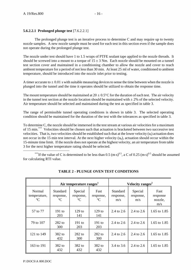
A 19/Res.800 - 16 -
P:\DOCS\A 800.DOC
5.6.2.2.1 Prolonged plunge test [7.6.2.2.1]
The prolonged plunge test is an iterative process to determine C and may require up to twenty nozzle samples. A new nozzle sample must be used for each test in this section even if the sample does not operate during the prolonged plunge test. The nozzle under test should have 1 to 1.5 wraps of PTFE sealant tape applied to the nozzle threads. It should be screwed into a mount to a torque of 15 ± 3 Nm. Each nozzle should be mounted on a tunnel test section cover and maintained in a conditioning chamber to allow the nozzle and cover to reach ambient temperature for a period of not less than 30 min. At least 25 ml of water, conditioned to ambient temperature, should be introduced into the nozzle inlet prior to testing. A timer accurate to ± 0.01 s with suitable measuring devices to sense the time between when the nozzle is plunged into the tunnel and the time it operates should be utilized to obtain the response time. The mount temperature should be maintained at 20 ± 0.5°C for the duration of each test. The air velocity in the tunnel test section at the nozzle location should be maintained with ± 2% of the selected velocity. Air temperature should be selected and maintained during the test as specified in table 3. The range of permissible tunnel operating conditions is shown in table 3. The selected operating condition should be maintained for the duration of the test with the tolerances as specified in table 3. To determine C, the nozzle should be immersed in the test stream at various air velocities for a maximum of 15 min.*** Velocities should be chosen such that actuation is bracketed between two successive test velocities. That is, two velocities should be established such that at the lower velocity (ul) actuation does not occur in the 15 min test interval. At the next higher velocity (uh), actuation should occur within the 15-minute time limit. If the nozzle does not operate at the highest velocity, an air temperature from table 3 for the next higher temperature rating should be selected.
***If the value of C is determined to be less than 0.5 (m⋅s)0.5, a C of 0.25 (m⋅s)0.5 should be assumed for calculating RTI value.
TABLE 2 - PLUNGE OVEN TEST CONDITIONS
Air temperature ranges1
Velocity ranges2
Normal
temperature, ºC
Standard response,
ºC
Special
response, ºC
Fast
response, ºC
Standard response,
m/s
Special
response, m/s
Fast
response nozzle,
m/s
57 to 77
191 to 203
129 to
141
129 to
141
2.4 to 2.6
2.4 to 2.6
1.65 to 1.85
79 to 107
282 to
300
191 to
203
191 to
203
2.4 to 2.6
2.4 to 2.6
1.65 to 1.85
121 to 149
382 to
432
282 to
300
282 to
300
2.4 to 2.6
2.4 to 2.6
1.65 to 1.85
163 to 191
382 to
432
382 to
432
382 to
432
3.4 to 3.6
2.4 to 2.6
1.65 to 1.85
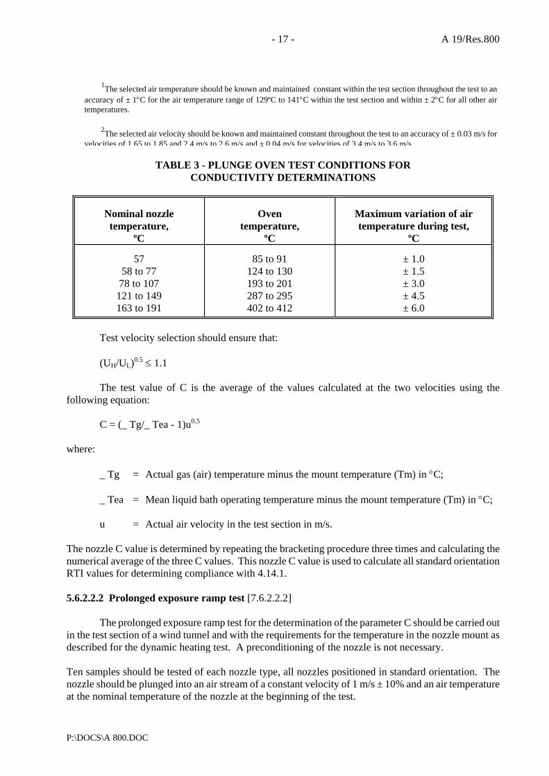
- 17 - A 19/Res.800
P:\DOCS\A 800.DOC
1The selected air temperature should be known and maintained constant within the test section throughout the test to an
accuracy of ± 1°C for the air temperature range of 129ºC to 141°C within the test section and within ± 2°C for all other air temperatures.
2The selected air velocity should be known and maintained constant throughout the test to an accuracy of ± 0.03 m/s for velocities of 1.65 to 1.85 and 2.4 m/s to 2.6 m/s and ± 0.04 m/s for velocities of 3.4 m/s to 3.6 m/s.
TABLE 3 - PLUNGE OVEN TEST CONDITIONS FOR CONDUCTIVITY DETERMINATIONS
Nominal nozzle temperature,
ºC
Oven
temperature, ºC
Maximum variation of air temperature during test,
ºC
57 58 to 77
78 to 107 121 to 149 163 to 191
85 to 91
124 to 130 193 to 201 287 to 295 402 to 412
± 1.0 ± 1.5 ± 3.0 ± 4.5 ± 6.0
Test velocity selection should ensure that:
(UH/UL)0.5 ≤ 1.1
The test value of C is the average of the values calculated at the two velocities using the
following equation:
C = (_ Tg/_ Tea - 1)u0.5 where:
_ Tg = Actual gas (air) temperature minus the mount temperature (Tm) in °C;
_ Tea = Mean liquid bath operating temperature minus the mount temperature (Tm) in °C;
u = Actual air velocity in the test section in m/s. The nozzle C value is determined by repeating the bracketing procedure three times and calculating the numerical average of the three C values. This nozzle C value is used to calculate all standard orientation RTI values for determining compliance with 4.14.1. 5.6.2.2.2 Prolonged exposure ramp test [7.6.2.2.2]
The prolonged exposure ramp test for the determination of the parameter C should be carried out in the test section of a wind tunnel and with the requirements for the temperature in the nozzle mount as described for the dynamic heating test. A preconditioning of the nozzle is not necessary. Ten samples should be tested of each nozzle type, all nozzles positioned in standard orientation. The nozzle should be plunged into an air stream of a constant velocity of 1 m/s ± 10% and an air temperature at the nominal temperature of the nozzle at the beginning of the test.
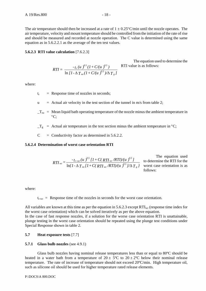
A 19/Res.800 - 18 -
P:\DOCS\A 800.DOC
The air temperature should then be increased at a rate of 1 ± 0.25°C/min until the nozzle operates. The air temperature, velocity and mount temperature should be controlled from the initiation of the rate of rise and should be measured and recorded at nozzle operation. The C value is determined using the same equation as in 5.6.2.2.1 as the average of the ten test values. 5.6.2.3 RTI value calculation [7.6.2.3]
The equation used to determine the RTI value is as follows:
where:
tr = Response time of nozzles in seconds;
u = Actual air velocity in the test section of the tunnel in m/s from table 2;
_Tea = Mean liquid bath operating temperature of the nozzle minus the ambient temperature in °C;
_Tg = Actual air temperature in the test section minus the ambient temperature in °C;
C = Conductivity factor as determined in 5.6.2.2.
5.6.2.4 Determination of worst case orientation RTI
The equation used to determine the RTI for the worst case orientation is as follows:
where:
tr-wc = Response time of the nozzles in seconds for the worst case orientation. All variables are known at this time as per the equation in 5.6.2.3 except RTIwc (response time index for the worst case orientation) which can be solved iteratively as per the above equation. In the case of fast response nozzles, if a solution for the worse case orientation RTI is unattainable, plunge testing in the worst case orientation should be repeated using the plunge test conditions under Special Response shown in table 2. 5.7 Heat exposure tests [7.7] 5.7.1 Glass bulb nozzles (see 4.9.1)
Glass bulb nozzles having nominal release temperatures less than or equal to 80ºC should be heated in a water bath from a temperature of 20 ± 5ºC to 20 ± 2ºC below their nominal release temperature. The rate of increase of temperature should not exceed 20ºC/min. High temperature oil, such as silicone oil should be used for higher temperature rated release elements.
]T )/)C/(u + (1 T -[1 ))C/(u + (1 )(u t- = RTI
g0.5
ea
0.50.5r
∆∆ln
}T ]/)/RTI)/(uRTIC(+[1T -{1])/RTI)/(uRTIC( + [1 )(u t- = RTI
g0.5
wcea
0.5wc
0.5wc-r
wc∆∆ln
- 19 - A 19/Res.800
P:\DOCS\A 800.DOC
This temperature should then be increased at a rate of 1°C/min to the temperature at which the gas bubble dissolves, or to a temperature 5°C lower than the nominal operating temperature, whichever is lower. The nozzle should be removed from the liquid bath and allowed to cool in air until the gas bubble has formed again. During the cooling period, the pointed end of the glass bulb (seal end) should be pointing downwards. This test should be performed four times on each of four nozzles. 5.7.2 All uncoated nozzles (see 4.9.2) [7.7.2]
Twelve uncoated nozzles should be exposed for a period of 90 days to a high ambient temperature that is 11°C below the nominal rating or at the temperature shown in table 4, whichever is lower, but not less than 49ºC. If the service load is dependent on the service pressure, nozzles should be tested under the rated working pressure. After exposure, four of the nozzles should be subjected to the tests specified in 5.4.1, four nozzles to the test of 5.5.1, two at the minimum operating pressure and two at the rated working pressure, and four nozzles to the requirements of 4.3. If a nozzle fails the applicable requirements of a test, eight additional nozzles should be tested as described above and subjected to the test in which the failure was recorded. All eight nozzles should comply with the test requirements. 5.7.3 Coated nozzles (see 4.9.3) [7.7.3]
In addition to the exposure test of 5.7.2 in an uncoated version, 12 coated nozzles should be exposed to the test of 5.7.2 using the temperatures shown in table 4 for coated nozzles. The test should be conducted for 90 days. During this period, the sample should be removed from the oven at intervals of approximately 7 days and allowed to cool for 2 h to 4 h. During this cooling period, the sample should be examined. After exposure, four of the nozzles should be subjected to the tests specified in 5.4.1, four nozzles to the test of 5.5.1; two at the minimum operating pressure and two at the rated working pressure, and four nozzles to the requirements of 4.3.
A 19/Res.800 - 20 -
P:\DOCS\A 800.DOC
TABLE 4 - TEST TEMPERATURES FOR COATED AND UNCOATED NOZZLES
Values in ºC
Nominal release
temperature
Uncoated nozzle test
temperature
Coated nozzle test
temperature
57-60 61-77
78-107 108-149 150-191 192-246 247-302 303-343
49 52 79
121 149 191 246 302
49 49 66
107 149 191 246 302
5.8 Thermal shock test for glass bulb nozzles (see 4.10) [7.8]
Before starting the test, at least 24 nozzles at room temperature of 20ºC to 25ºC for at least 30 min should be conditioned. The nozzles should be immersed in a bath of liquid, the temperature of which should be 10 ± 2ºC below the nominal release temperature of the nozzles. After 5 min, the nozzles should be removed from the bath and immersed immediately in another bath of liquid, with the bulb seal downwards, at a temperature of 10 ± 1ºC. Then the nozzles should be tested in accordance with 5.5.1. 5.9 Strength tests for release elements [7.9] 5.9.1 Glass bulbs (see 4.7.1) [7.9.1]
At least 15 samples bulbs in the lowest temperature rating of each bulb type should be positioned individually in a test fixture using the sprinkler seating parts. Each bulb should then be subjected to a uniformly increasing force at a rate not exceeding 250 N/s in the test machine until the bulb fails. Each test should be conducted with the bulb mounted in new seating parts. The mounting device may be reinforced externally to prevent its collapse, but in a manner which does not interfere with bulb failure. The failure load for each bulb should be recorded. Calculation of the lower tolerance limit (TL1) for bulb strength should be made. Using the values of service load recorded in 5.3.1, the upper tolerance limit (TL2) for the bulb design load should be made. Compliance with 4.7.1 should be verified. 5.9.2 Fusible elements (see 4.7.2) 5.10 Water flow test (see 4.4.1) [7.10]
The nozzle and a pressure gauge should be mounted on a supply pipe. The water flow should be measured at pressures ranging from the minimum operating pressure to the rated working pressure at intervals of approximately 10% of the service pressure range on two sample nozzles. In one series of tests, the pressure should be increased from zero to each value and, in the next series, the pressure should be decreased from the rated pressure to each value. The flow constant K should be averaged from each series of readings, i.e., increasing pressure and decreasing pressure. During the test, pressures should be corrected for differences in height between the gauge and the outlet orifice of the nozzle.
- 21 - A 19/Res.800
P:\DOCS\A 800.DOC
5.11 Water distribution and droplet size tests 5.11.1 Water distribution (see 4.4.2)
The tests should be conducted in a test chamber of minimum dimensions 7 m x 7 m or 300% of the maximum design area being tested, whichever is greater. For standard automatic nozzles, a single open nozzle should be installed and then four open nozzles of the same type arranged in a square, at maximum spacings specified by the manufacturer, on piping prepared for this purpose. For pilot type nozzles, a single nozzle should be installed and then the maximum number of slave nozzles at their maximum spacings, specified in the manufacturer's design and installation instructions. The distance between the ceiling and the distribution plate should be 50 mm for upright nozzles and 275 mm for pendent nozzles. For nozzles without distribution plates, the distances should be measured from the ceiling to the highest nozzle outlet. Recessed, flush and concealed type nozzles should be mounted in a false ceiling of dimensions not less than 6 m x 6 m and arranged symmetrically in the test chamber. The nozzles should be fitted directly into the horizontal pipework by means of "T" or elbow fittings. The water discharge distribution in the protected area below a single nozzle and between the multiple nozzles should be collected and measured by means of square measuring containers nominally 300 mm on a side. The distance between the nozzles and the upper edge of the measuring containers should be the maximum specified by the manufacturer. The measuring containers should be positioned centrally, beneath the single nozzle and beneath the multiple nozzles. The nozzles should be discharged both at the minimum operating and rated working pressures specified by the manufacturer and the minimum and maximum installation heights specified by the manufacturer. The water should be collected for at least 10 min to assist in characterizing nozzle performance. 5.11.2 Water droplet size (see 4.4.3)
The mean water droplet diameters, velocities, droplet size distribution, number density and volume flux should be determined at both the minimum and maximum flow rates specified by the manufacturer. Once the data is gathered, the method of the "Standard practice for determining data criteria and processing for liquid drop size analysis" (ASTM E799-92) will be used to determine the appropriate sample size, class size widths, characteristic drop sizes and measured dispersion of the drop size distribution. This data should be taken at various points within the spray distribution as described in 4.4.3. 5.12 Corrosion tests [7.12] 5.12.1 Stress corrosion test for brass nozzle parts (see 4.11.1)
Five nozzles should be subjected to the following aqueous ammonia test. The inlet of each nozzle should be sealed with a non-reactive cap, e.g. plastic. The samples should be degreased and exposed for 10 days to a moist ammonia-air mixture in a glass container of volume 0.02 ± 0.01 m³. An aqueous ammonia solution, having a density of 0.94 g/cm³, should be maintained in the bottom of the

A 19/Res.800 - 22 -
P:\DOCS\A 800.DOC
container, approximately 40 mm below the bottom of the samples. A volume of aqueous ammonia solution corresponding to 0.01 ml per cubic centimeter of the volume of the container will give approximately the following atmospheric concentrations: 35% ammonia, 5% water vapour, and 60% air. The inlet of each sample should be sealed with a non-reactive cap, e.g. plastic. The moist ammonia-air mixture should be maintained as closely as possible at atmospheric pressure, with the temperature maintained at 34 ± 2°C. Provision should be made for venting the chamber via a capillary tube to avoid the build-up of pressure. Specimens should be shielded from condensate drippage. After exposure, the nozzles should be rinsed and dried, and a detailed examination should be conducted. If a crack, delamination or failure of any operating part is observed, the nozzle(s) should be subjected to a leak resistance test at the rated pressure for 1 min and to the functional test at the minimum flowing pressure (see 4.5.1). Nozzles showing cracking, delamination or failure of any non-operating part should not show evidence of separation of permanently attached parts when subjected to flowing water at the rated working pressure for 30 min. 5.12.2 Stress-Corrosion Cracking of Stainless Steel Nozzle Parts (see 4.11.1) 5.12.2.1 Five samples are to be degreased prior to being exposed to the magnesium chloride solution. 5.12.2.2 Parts used in nozzles should be placed in a 500-millilitre flask that is fitted with a thermometer and a wet condenser approximately 760 mm long. The flask should be filled approximately one-half full with a 42% by weight magnesium chloride solution, placed on a thermostatically-controlled electrically heated mantel, and maintained at a boiling temperature of 150±1°C. The parts should be unassembled, that is, not contained in a nozzle assembly. The exposure should last for 500 h. 5.12.2.3 After the exposure period, the test samples should be removed from the boiling magnesium chloride solution and rinsed in deionized water. 5.12.2.4 The test samples should then be examined using a microscope having a magnification of 25X for any cracking, delamination, or other degradation as a result of the test exposure. Test samples exhibiting degradation should be tested as described in 5.12.2.5 or 5.12.2.6, as applicable. Test samples not exhibiting degradation are considered acceptable without further test. 5.12.2.5 Operating parts exhibiting degradation should be further tested as follows. Five new sets of parts should be assembled in nozzle frames made of materials that do not alter the corrosive effects of the magnesium chloride solution on the stainless steel parts. These test samples should be degreased and subjected to the magnesium chloride solution exposure specified in 5.12.2.2. Following the exposure, the test samples should withstand, without leakage, a hydrostatic test pressure equal to the rated working pressure for 1 min and then be subjected to the functional test at the minimum operating pressure in accordance with 5.5.1. 5.12.2.6 Non-operating parts exhibiting degradation should be further tested as follows. Five new sets of parts should be assembled in nozzle frames made of materials that do not alter the corrosive effects of the magnesium chloride solution on the stainless steel parts. These test samples should be degreased and subjected to the magnesium chloride solution exposure specified in paragraph 5.12.4.1. Following the exposure, the test samples should withstand a flowing pressure equal to the rated working pressure for 30 min without separation of permanently attached parts. 5.12.3 Sulphur dioxide corrosion test (see 4.11.2 and 4.14.2)
- 23 - A 19/Res.800
P:\DOCS\A 800.DOC
Ten nozzles should be subjected to the following sulphur dioxide corrosion test. The inlet of each
sample should be sealed with a non-reactive cap, e.g. plastic. The test equipment should consist of a 5-litre vessel (instead of a 5-litre vessel, other volumes up to 15 litres may be used in which case the quantities of chemicals given below should be increased in proportion) made of heat-resistant glass, with a corrosion-resistant lid of such a shape as to prevent condensate dripping on the nozzles. The vessel should be electrically heated through the base and provided with a cooling coil around the side walls. A temperature sensor placed centrally 160 ± 20 mm above the bottom of the vessel should regulate the heating so that the temperature inside the glass vessel is 45 ± 3°C. During the test, water should flow through the cooling coil at a sufficient rate to keep the temperature of the discharge water below 30°C. This combination of heating and cooling should encourage condensation on the surfaces of the nozzles. The sample nozzles should be shielded from condensate drippage. The nozzles to be tested should be suspended in their normal mounting position under the lid inside the vessel and subjected to a corrosive sulphur dioxide atmosphere for 8 days. The corrosive atmosphere should be obtained by introducing a solution made up by dissolving 20 g of sodium thiosulfate (Na2S2O3H2O) crystals in 500 ml of water. For at least six days of the 8-day exposure period, 20 ml of dilute sulphuric acid consisting of 156 ml of normal H2SO4 (0.5 mol/l) diluted with 844 ml of water should be added at a constant rate. After 8 days, the nozzles should be removed from the container and allowed to dry for 4 to 7 days at a temperature not exceeding 35°C with a relative humidity not greater than 70%. After the drying period, five nozzles should be subjected to a functional test at the minimum operating pressure in accordance with 5.5.1 and five nozzles should be subjected to the dynamic heating test in accordance with 4.14.2. 5.12.4 Salt spray corrosion test (see 4.11.3 and 4.14.2) [7.12.3] 5.12.4.1 Nozzles intended for normal atmospheres
Ten nozzles should be exposed to a salt spray within a fog chamber. The inlet of each sample should be sealed with a non-reactive cap, e.g. plastic. During the corrosive exposure, the inlet thread orifice should be sealed by a plastic cap after the nozzles have been filled with deionized water. The salt solution should be a 20% by mass sodium chloride solution in distilled water. The pH should be between 6.5 and 3.2 and the density between 1.126 g/ml and 1.157 g/ml when atomized at 35°C. Suitable means of controlling the atmosphere in the chamber should be provided. The specimens should be supported in their normal operating position and exposed to the salt spray (fog) in a chamber having a volume of at least 0.43 m³ in which the exposure zone should be maintained at a temperature of 35 ± 2°C. The temperature should be recorded at least once per day, at least 7 h apart (except weekends and holidays when the chamber normally would not be opened). Salt solution should be supplied from a recirculating reservoir through air-aspirating nozzles, at a pressure between 0.7 bar (0.07 MPa) and 1.7 bar (0.17 MPa). Salt solution runoff from exposed samples should be collected and should not return to the reservoir for recirculation. The sample nozzles should be shielded from condensate drippage. Fog should be collected from at least two points in the exposure zone to determine the rate of application and salt concentration. The fog should be such that for each 80 cm² of collection area, 1 ml to 2 ml of solution should be collected per hour over a 16-hour period and the salt concentration should be 20 ± 1%
A 19/Res.800 - 24 -
P:\DOCS\A 800.DOC
by mass. The nozzles should withstand exposure to the salt spray for a period of 10 days. After this period, the nozzles should be removed from the fog chamber and allowed to dry for 4 to 7 days at a temperature of 20ºC to 25°C in an atmosphere having a relative humidity not greater than 70%. Following the drying period, five nozzles should be submitted to the functional test at the minimum operating pressure in accordance with 5.5.1 and five nozzles should be subjected to the dynamic heating test in accordance with 4.14.2. 5.12.4.2 Nozzles intended for corrosive atmospheres [7.12.3.2]
Five nozzles should be subjected to the tests specified in 5.12.4.1 except that the duration of the salt spray exposure should be extended from 10 days to 30 days. 5.12.5 Moist air exposure test (see 4.11.4 and 4.14.2) [7.12.4]
Ten nozzles should be exposed to a high temperature-humidity atmosphere consisting of a relative humidity of 98 ± 2% and a temperature of 95 ± 4ºC. The nozzles should be installed on a pipe manifold containing deionized water. The entire manifold should be placed in the high temperature-humidity enclosure for 90 days. After this period, the nozzles should be removed from the temperature-humidity enclosure and allowed to dry for 4 to 7 days at a temperature of 25 ± 5°C in an atmosphere having a relative humidity of not greater than 70%. Following the drying period, five nozzles should be functionally tested at the minimum operating pressure in accordance with 5.5.1 and five nozzles should be subjected to the dynamic heating test in accordance with 4.14.2.* 5.13 Nozzle coating tests [7.13] 5.13.1 Evaporation test (see 4.12.1) [7.13.1]
A 50 cm³ sample of wax or bitumen should be placed in a metal or glass cylindrical container, having a flat bottom, an internal diameter of 55 mm and an internal height of 35 mm. The container, without lid, should be placed in an automatically controlled electric, constant ambient temperature oven with air circulation. The temperature in the oven should be controlled at 16°C below the nominal release temperature of the nozzle, but at not less than 50°C. The sample should be weighed before and after a 90-day exposure to determine any loss of volatile matter. The sample should meet the requirements of 4.12.1.
*At the manufacturer's option, additional samples may be furnished for this test to provide early evidence of failure. The additional samples may be removed from the test chamber at 30-day intervals for testing.
5.13.2 Low-temperature test (see 4.12.2) [7.13.2]
Five nozzles, coated by normal production methods, whether with wax, bitumen or a metallic coating, should be subjected to a temperature of -10°C for a period of 24 h. On removal from the low-temperature cabinet, the nozzles should be exposed to normal ambient temperature for at least 30 min before examination of the coating to the requirements of 4.12.2. 5.14 Heat resistance test (see 4.15) [7.14]
One nozzle body should be heated in an oven at 800°C for a period of 15 min, with the nozzle in

- 25 - A 19/Res.800
P:\DOCS\A 800.DOC
its normal installed position. The nozzle body should then be removed, holding it by the threaded inlet, and should be promptly immersed in a water bath at a temperature of approximately 15°C. It should meet the requirements of 4.15. 5.15 Water hammer test (see 4.13) [7.15]
Five nozzles should be connected, in their normal operating position, to the test equipment. After purging the air from the nozzles and the test equipment, 3,000 cycles of pressure varying from 4 ± 2 bar (0.4 ± 0.2 MPa) to twice the rated working pressure should be generated. The pressure should be raised from 4 bar to twice the rated pressure at a rate of 60 ± 10 bar/s. At least 30 cycles of pressure per minute should be generated. The pressure should be measured with an electrical pressure transducer. Each nozzle should be visually examined for leakage during the test. After the test, each nozzle should meet the leakage resistance requirement of 4.8.1 and the functional requirement of 4.5.1 at the minimum operating pressure. 5.16 Vibration test (see 4.16) [7.16] 5.16.1 Five nozzles should be fixed vertically to a vibration table. They should be subjected at room temperature to sinusoidal vibrations. The direction of vibration should be along the axis of the connecting thread. 5.16.2 The nozzles should be vibrated continuously from 5 Hz to 40 Hz at a maximum rate of 5 min/octave and an amplitude of 1 mm (1/2 peak-to-peak value). If one or more resonant points are detected, the nozzles after coming to 40 Hz, should be vibrated at each of these resonant frequencies for 120 h/number of resonances. If no resonances are detected, the vibration from 5 Hz to 40 Hz should be continued for 120 h. 5.16.3 The nozzle should then be subjected to the leakage test in accordance with 4.8.1 and the functional test in accordance with 4.5.1 at the minimum operating pressure. 5.17 Impact test (see 4.17) [7.17]
Five nozzles should be tested by dropping a mass onto the nozzle along the axial centreline of waterway. The kinetic energy of the dropped mass at the point of impact should be equivalent to a mass equal to that of the test nozzle dropped from a height of 1 m (see figure 2). The mass should be prevented from impacting more than once upon each sample. Following the test, a visual examination of each nozzle should show no signs of fracture, deformation or other deficiency. If none is detected, the nozzles should be subjected to the leak resistance test, described in 5.4.1. Following the leakage test, each sample should meet the functional test requirement of 5.5.1 at a pressure equal to the minimum flowing pressure. 5.18 Lateral discharge test (see 4.18) [7.19]
Water should be discharged from a spray nozzle at the minimum operating and rated working pressure. A second automatic nozzle located at the minimum distance specified by the manufacturer should be mounted on a pipe parallel to the pipe discharging water. The nozzle orifices or distribution plates (if used) should be placed 550 mm, 356 mm and 152 mm below a flat smooth ceiling for three separate tests, respectively at each test pressure. The top of a square pan measuring 305 mm square and 102 mm deep should be positioned 152 mm below the heat responsive element for each test. The pan should be filled with 0.47 l of heptane. After ignition, the automatic nozzle should operate before the heptane is consumed.

A 19/Res.800 - 26 -
P:\DOCS\A 800.DOC
5.19 30-day leakage test (see 4.19) [7.20]
Five nozzles should be installed on a water filled test line maintained under a constant pressure of twice the rated working pressure for 30 days at an ambient temperature of 20 ± 5°C. The nozzles should be inspected visually at least weekly for leakage. Following completion of this 30-day test, all samples should meet the leak resistance requirements specified in 4.8 and should exhibit no evidence of distortion or other mechanical damage. 5.20 Vacuum test (see 4.20) [7.21]
Three nozzles should be subjected to a vacuum of 460 mm of mercury applied to a nozzle inlet for 1 min at an ambient temperature of 20 ± 5°C. Following this test, each sample should be examined to verify that no distortion or mechanical damage has occurred and then should meet the leak resistance requirements specified in 5.4.1. 5.21 Clogging test (see 4.22) [7.28] 5.21.1 The water flow rate of an open water mist nozzle with its strainer or filter should be measured at its rated working pressure. The nozzle and strainer or filter should then be installed in test apparatus described in figure 3 and subjected to 30 min of continuous flow at rated working pressure using contaminated water which has been prepared in accordance with 5.21.3. 5.21.2 Immediately following the 30 min of continuous flow with the contaminated water, the flow rate of the nozzle and strainer or filter should be measured at rated working pressure. No removal, cleaning or flushing of the nozzle, filter or strainer is permitted during the test. 5.21.3 The water used during the 30 min of continuous flow at rated working pressure specified in 5.21.1 should consist of 60 l of tap water into which has been mixed 1.58 kg of contaminants which sieve as described in table 5. The solution should be continuously agitated during the test.

- 27 - A 19/Res.800
P:\DOCS\A 800.DOC
TABLE 5 CONTAMINANT FOR CONTAMINATED WATER CYCLING TEST
GRAMS OF CONTAMINANT (+ 5% )2
SIEVE DESIGNATION1
NOMINAL SIEVE OPENING, MM
PIPE SCALE
TOP SOIL
SAND
No. 25
0.706
-
456
200
No. 50
0.297
82
82
327
No.100
0.150
84
6
89
No.200
0.074
81
-
21
No.325
0.043
153
-
3
TOTAL
400
544
640
1Sieve designations correspond with those specified in the standard for wire-cloth sieves for testing purposes,
ASTM E11-87, CENCO-MEINZEN sieve sizes 25 mesh, 50 mesh, 100 mesh, 200 mesh and 325 mesh, corresponding with the number designation in the table, have been found to comply with ASTM E11-87.
2The amount of contaminant may be reduced by 50% for nozzles limited to use with copper or stainless steel piping and by 90% for nozzles having a rated pressure of 50 bar or higher and limited to use with stainless steel piping.
6 WATER MIST NOZZLE MARKINGS 6.1 General
Each nozzle complying with the requirements of this standard should be permanently marked as follows:
.1 trademark or manufacturer's name;
.2 model identification;
.3 manufacturer's factory identification. This is only required if the manufacturer has more than one nozzle manufacturing facility;
.4 nominal year of manufacture* (automatic nozzles only);
.5 nominal release temperature** (automatic nozzles only); and
*The year of manufacture may include the last three months of the preceding year and the first six
months of the following year. Only the last two digits need be indicated.
**Except for coated and plated nozzles, the nominal release temperature range should be color-coded on the nozzle to identify the nominal rating. The colour code should be visible on the yoke arms holding the distribution plate for fusible element nozzles, and should be indicated by the colour of the liquid in glass bulbs. The nominal temperature rating should be stamped or cast on the fusible element of fusible element nozzles. All nozzles should be stamped, cast, engraved or colour-coded in such a way that the nominal rating is recognizable even if the nozzle has operated. This should be in accordance with table 1.
A 19/Res.800 - 28 -
P:\DOCS\A 800.DOC
.6 K-factor. This is only required if a given model nozzle is available with more than
1 orifice size.
In countries where colour-coding of yoke arms of glass bulb nozzles is required, the colour code for fusible element nozzles should be used. 6.2 Nozzle housings
Recessed housings, if provided, should be marked for use with the corresponding nozzles unless the housing is a non-removable part of the nozzle.
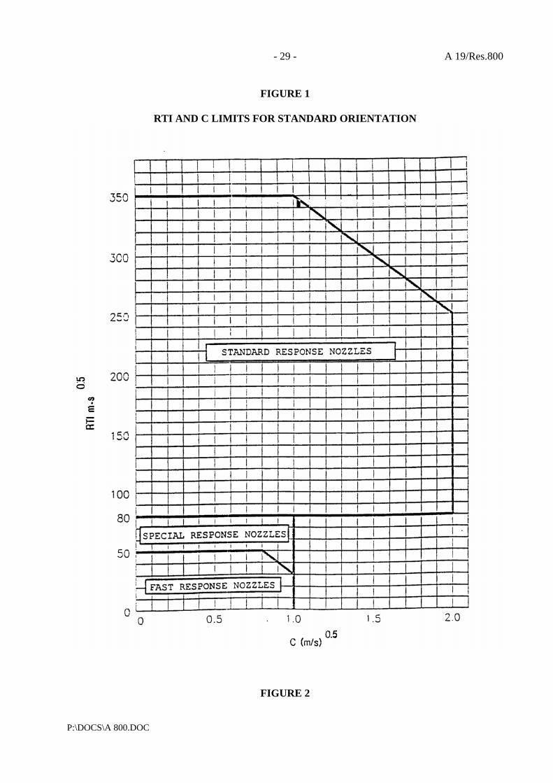
- 29 - A 19/Res.800
P:\DOCS\A 800.DOC
FIGURE 1
RTI AND C LIMITS FOR STANDARD ORIENTATION
FIGURE 2
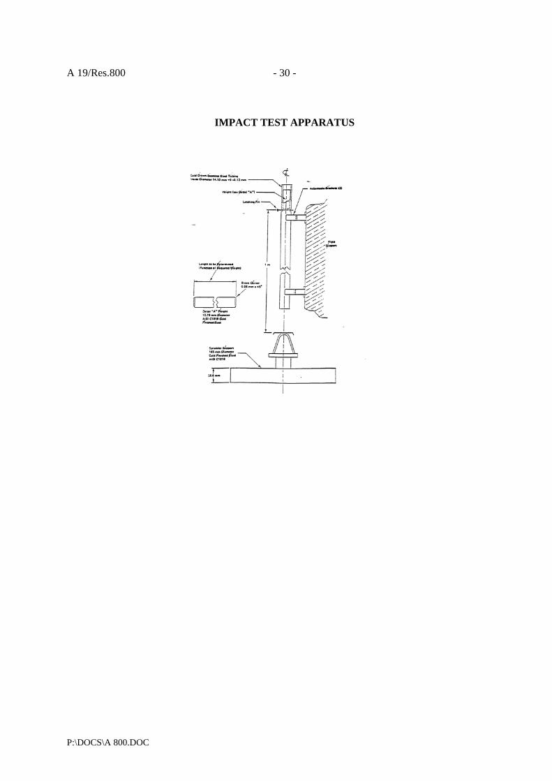
A 19/Res.800 - 30 -
P:\DOCS\A 800.DOC
IMPACT TEST APPARATUS

- 31 - A 19/Res.800
P:\DOCS\A 800.DOC
FIGURE 3
CLOGGING TEST APPARATUS

A 19/Res.800 - 32 -
P:\DOCS\A 800.DOC
APPENDIX 2
FIRE TEST PROCEDURES FOR EQUIVALENT SPRINKLER SYSTEMS IN ACCOMMODATION, PUBLIC SPACE AND
SERVICE AREAS ON PASSENGER SHIPS 1 SCOPE 1.1 These test procedures describe a fire test method for evaluating the effectiveness of sprinkler systems equivalent to systems covered by regulation II-2/12 of the SOLAS Convention [1*] in accommodation and service areas on board ships. It should be noted that the test method is limited to the systems' effectiveness against fire and is not intended for testing of the quality and design parameters of the individual components in the system. 1.2 In order to fulfil the requirements of 3.5 of the guidelines, the system must be capable of fire control or suppression in a wide variety of fire loading, fuel arrangement, room geometry and ventilation conditions. 1.3 Products employing materials or having forms of construction differing from the requirements contained herein may be examined and tested in accordance with the intent of the requirements and, if found to be substantially equivalent, may be judged to comply with this document. 1.4 Products complying with the text of this document will not necessarily be judged to comply, if, when examined and tested, are found to have other features which impair the level of safety contemplated by this document. 2 HAZARD AND OCCUPANCY CLASSIFICATIONS
For the purposes of identifying the different fire risk classifications, table 1 is given, which correlates the fire tests with the classification of occupancy defined in SOLAS regulation II-2/26[1]:
*Figures in square brackets in the text indicate the referenced publications listed later in this document.
Table 1
Correlation between fire tests with the classification of occupancy defined in SOLAS regulation II-2/26.2.2
Corresponding fire test
Occupancy classification
Sectio
n 5 cabin
Section
5 corridor
Section 6 luxury cabin
Section
7 public spaces
Section
8 shopping and
storage (1) Control stations
X
(2) Stairways
X 1

- 33 - A 19/Res.800
P:\DOCS\A 800.DOC
(3) Corridors X 1 (6) Accommodation spaces
of minor fire risk
X 2
X 3
X 4
(7) Accommodation spaces
of moderate fire risk
X 2
X 3
X 4
(8) Accommodation spaces
of greater fire risk
X
(9) Sanitary & similar
spaces
X 2
X 3
X 4
(13) Store rooms,
workshops, pantries, etc.
X
(14) Other spaces in which
flammable liquids are stowed
X
Note: For examples of occupancies in each category, see SOLAS regulation II-2/26[1]
1 For corridors and stairways wider than 1.5 m, use section 7 public space fire test instead of the
corridor fire test
2 For spaces up to 12 m2
3 For spaces from 12 m2 up to 50 m2
4 For spaces over 50 m2 . 3 DEFINITIONS 3.1 Fire suppression: Sharply reducing the heat release rate of a fire and preventing its regrowth by means of a direct and sufficient application of water through the fire plume to the burning fuel surface [2]. 3.2 Fire control: Limiting the size of a fire by distribution of water so as to decrease the heat release rate and pre-wet adjacent combustibles, while controlling ceiling gas temperatures to avoid structural damage [2]. 3.3 Fire source: Fire source is defined as the combustible material in which the fire is set and the combustible material covering walls and ceiling. 3.4 Igniter: The device used to ignite the fire source.

A 19/Res.800 - 34 -
P:\DOCS\A 800.DOC
4 GENERAL REQUIREMENTS 4.1 Nozzle positioning
The testing organization should be responsible for assuring that the nozzles for each fire test are installed in accordance with the manufacturer's design and installation instructions. The tests should be performed at the maximum specified spacings, installation height and distances below the ceiling. In addition, if the testing organization finds it necessary, selected fire tests should also be conducted at minimum specified spacings, installation height and distances below the ceiling. 4.2 Water pressure and flow rates
The testing organization should be responsible for assuring that all fire tests are conducted at the operating pressure and flow rates specified by the manufacturer. 4.3 Temperature measurements
Temperatures should be measured as described in detail under each chapter. Chromelalumel not exceeding 0.5 mm diameter welded together and chromelalumel 0.8 mm should be used. The 0.8 mm thermocouple wires should be twisted three times, have the end remaining wire cut off and be heated with an oxyacetylene torch to melt and form a small ball. The temperatures should be measured continuously, at least once every two seconds, throughout the tests. 4.4 Environmental conditions
The test hall should have an ambient temperature of between 10ºC to 30ºC at the start of each test. 4.5 Tolerances
Unless otherwise stated, the following tolerances should apply:
.1 Length ±2% of value
.2 Volume ±5% of value
.3 Pressure ±3% of value
.4 Temperature ±5% of value These tolerances are in accordance with ISO standard 6182-1, February 1994 edition [4]. 4.6 Observations
The following observations should be made during and after each test:
.1 Time of ignition.
.2 Activation time of each nozzle.
.3 Time when water flow is shut off.
.4 Damage to the fire source.

- 35 - A 19/Res.800
P:\DOCS\A 800.DOC
.5 Temperature recordings.
.6 System flow rate and pressure.
.7 Total number of operating nozzles.
4.7 Fire sources
If the requirements for fire sources specified in the following sections of this test method cannot be fulfilled, it is the responsibility of the test laboratory to show that alternative materials used have burning characteristics similar to those of specified materials. 4.8 Produce and documentation requirements
A draft copy of the design, installation and operating instruction manual should be furnished for use as a guide in the testing of the fire protection system devices. The instructions should reference the limitations of each device and should include at least the following items:
.1 Description and operating details of each device and all accessory equipment, including identification of extinguishing system components or accessory equipment by part or model number.
.2 Nozzle design recommendation and limitations for each fire type.
.3 Type and pressure rating of pipe, tubing and fittings to be used.
.4 Equivalent length values of all fittings and all system components through which water
flows.
.5 Discharge nozzle limitations, including maximum dimensional and area coverage, minimum and maximum installation height limitations, and nozzle permitted location in the protected volume.
.6 Range of filling capacities for each size storage container.
.7 Details for the proper installation of each device, including all component equipment.
.8 Reference to the specific types of detection and control panels (if applicable) to be
connected to the equipment.
.9 Operating pressure ranges of the system.
.10 Method of sizing pipe or tubing.
.11 Recommended orientation of tee fittings and the splitting of flows through tees.
.12 Maximum difference in operating (flowing) pressure between the hydraulically closest and most remote nozzle.
5 Cabin and corridor fire tests

A 19/Res.800 - 36 -
P:\DOCS\A 800.DOC
5.1 Test arrangement 5.1.1 The fire tests should be conducted in a 3 m by 4 m, 2.4 m high cabin connected to the centre of a 1.5 m by 12 m long corridor, 2.4 m high with both ends open. 5.1.2 The cabin should be fitted with one doorway opening, 0.8 m wide and 2.2 m high, which provides for a 0.2 m lintel above the opening. 5.1.3 The walls of the cabin should be constructed from an inner layer of nominally 12 mm thick non-combustible wall board with a nominally 45 mm thick mineral wool liner. The walls and ceiling of the corridor and ceiling of the cabin should be constructed of nominally 12 mm thick non-combustible wall boards. The cabin should be provided with a window in the wall opposite the corridor for observation purposes during the fire tests. 5.1.4 The cabin and corridor ceiling should be covered with cellulosic acoustical panels. The acoustical panels should be nominally 12 mm to 15 mm thick and should not ignite when tested in accordance with IMO resolution A.653(16). 5.1.5 Plywood panels should be placed on the cabin and corridor walls. The panels should be approximately 3 mm thick. The ignition time of the panel should not be more than 35 s and the flame spread time at 350 mm position should not be more than 100 s as measured in accordance with IMO resolution A.653(16). 5.2 Instrumentation
During each fire test, the following temperatures should be measured using thermocouples of diameter not exceeding 0.5 mm:
.1 The ceiling surface temperature above the ignition source in the cabin should be measured with a thermocouple embedded in the ceiling material from above such that the thermocouple bead is flush with the ceiling surface.
.2 The ceiling gas temperature should be measured with a thermocouple 75 ± 1 mm below
the ceiling in the centre of the cabin.
.3 The ceiling surface temperature in the centre of the corridor, directly opposite the cabin doorway, should be measured with a thermocouple embedded in the ceiling material such that the thermocouple bead is flush with the ceiling (see figure 1).
5.3 Nozzle positioning
The nozzles should be installed to protect the cabin and corridor in accordance with the manufacturer's design and installation instructions subject to the following:
.1 if only one nozzle is installed in the cabin, it may not be placed in the shaded areas in figure 2; and
.2 corridor nozzles should not be placed closer to the centreline of the cabin doorway than
one half the maximum spacing recommended by the manufacturer. An exception is systems where nozzles are required to be placed outside each doorway.
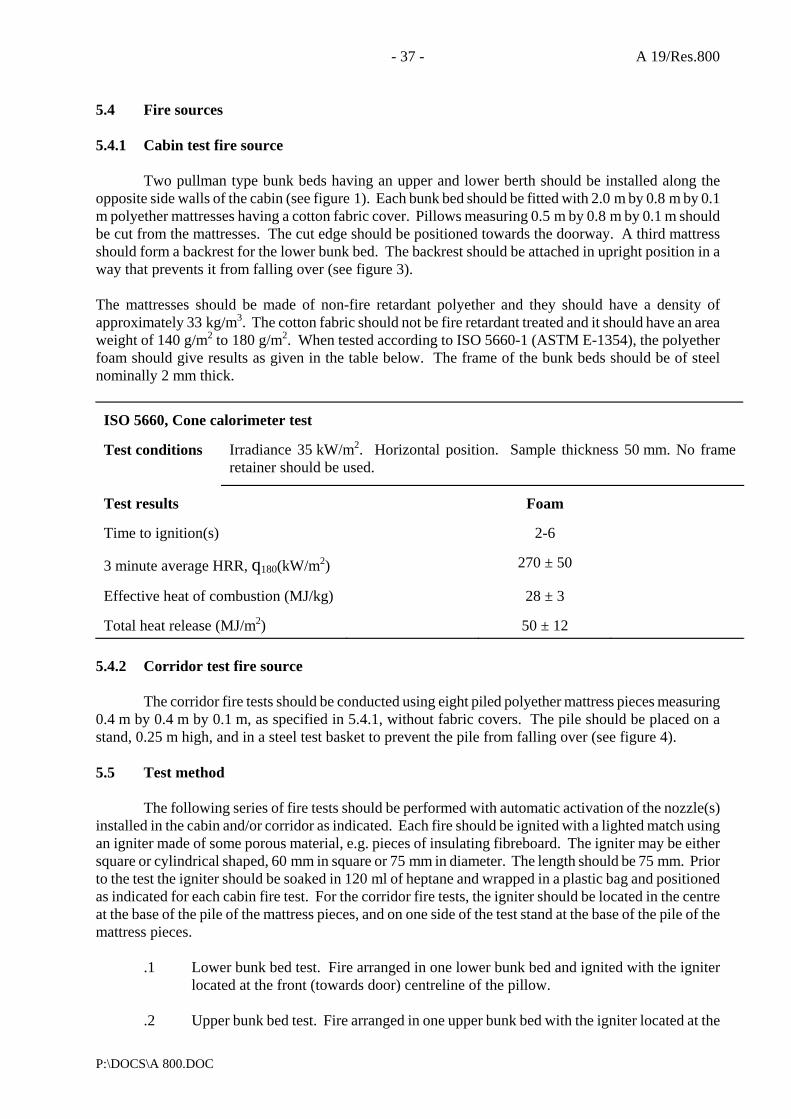
- 37 - A 19/Res.800
P:\DOCS\A 800.DOC
5.4 Fire sources 5.4.1 Cabin test fire source
Two pullman type bunk beds having an upper and lower berth should be installed along the opposite side walls of the cabin (see figure 1). Each bunk bed should be fitted with 2.0 m by 0.8 m by 0.1 m polyether mattresses having a cotton fabric cover. Pillows measuring 0.5 m by 0.8 m by 0.1 m should be cut from the mattresses. The cut edge should be positioned towards the doorway. A third mattress should form a backrest for the lower bunk bed. The backrest should be attached in upright position in a way that prevents it from falling over (see figure 3). The mattresses should be made of non-fire retardant polyether and they should have a density of approximately 33 kg/m3. The cotton fabric should not be fire retardant treated and it should have an area weight of 140 g/m2 to 180 g/m2. When tested according to ISO 5660-1 (ASTM E-1354), the polyether foam should give results as given in the table below. The frame of the bunk beds should be of steel nominally 2 mm thick.
ISO 5660, Cone calorimeter test Test conditions
Irradiance 35 kW/m2. Horizontal position. Sample thickness 50 mm. No frame retainer should be used.
Test results
Foam
Time to ignition(s)
2-6
3 minute average HRR, q180(kW/m2)
270 ± 50
Effective heat of combustion (MJ/kg)
28 ± 3
Total heat release (MJ/m2)
50 ± 12
5.4.2 Corridor test fire source
The corridor fire tests should be conducted using eight piled polyether mattress pieces measuring 0.4 m by 0.4 m by 0.1 m, as specified in 5.4.1, without fabric covers. The pile should be placed on a stand, 0.25 m high, and in a steel test basket to prevent the pile from falling over (see figure 4). 5.5 Test method
The following series of fire tests should be performed with automatic activation of the nozzle(s) installed in the cabin and/or corridor as indicated. Each fire should be ignited with a lighted match using an igniter made of some porous material, e.g. pieces of insulating fibreboard. The igniter may be either square or cylindrical shaped, 60 mm in square or 75 mm in diameter. The length should be 75 mm. Prior to the test the igniter should be soaked in 120 ml of heptane and wrapped in a plastic bag and positioned as indicated for each cabin fire test. For the corridor fire tests, the igniter should be located in the centre at the base of the pile of the mattress pieces, and on one side of the test stand at the base of the pile of the mattress pieces.
.1 Lower bunk bed test. Fire arranged in one lower bunk bed and ignited with the igniter located at the front (towards door) centreline of the pillow.
.2 Upper bunk bed test. Fire arranged in one upper bunk bed with the igniter located at the
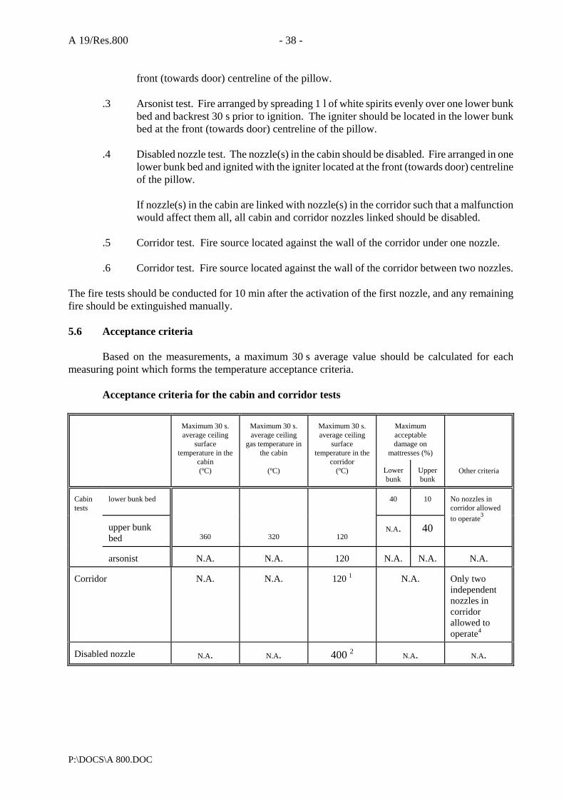
A 19/Res.800 - 38 -
P:\DOCS\A 800.DOC
front (towards door) centreline of the pillow.
.3 Arsonist test. Fire arranged by spreading 1 l of white spirits evenly over one lower bunk bed and backrest 30 s prior to ignition. The igniter should be located in the lower bunk bed at the front (towards door) centreline of the pillow.
.4 Disabled nozzle test. The nozzle(s) in the cabin should be disabled. Fire arranged in one
lower bunk bed and ignited with the igniter located at the front (towards door) centreline of the pillow.
If nozzle(s) in the cabin are linked with nozzle(s) in the corridor such that a malfunction would affect them all, all cabin and corridor nozzles linked should be disabled.
.5 Corridor test. Fire source located against the wall of the corridor under one nozzle.
.6 Corridor test. Fire source located against the wall of the corridor between two nozzles.
The fire tests should be conducted for 10 min after the activation of the first nozzle, and any remaining fire should be extinguished manually. 5.6 Acceptance criteria
Based on the measurements, a maximum 30 s average value should be calculated for each measuring point which forms the temperature acceptance criteria.
Acceptance criteria for the cabin and corridor tests
Maximum acceptable damage on
mattresses (%)
Maximum 30 s. average ceiling
surface temperature in the
cabin (ºC)
Maximum 30 s. average ceiling
gas temperature in the cabin
(ºC)
Maximum 30 s. average ceiling
surface temperature in the
corridor (ºC)
Lower bunk
Upper bunk
Other criteria
Cabin tests
lower bunk bed
40
10
upper bunk bed
360
320
120
N.A.
40
No nozzles in corridor allowed to operate3
arsonist
N.A.
N.A.
120
N.A.
N.A.
N.A.
Corridor
N.A.
N.A.
120 1
N.A.
Only two independent nozzles in corridor allowed to operate4
Disabled nozzle
N.A.
N.A.
400 2
N.A.
N.A.

- 39 - A 19/Res.800
P:\DOCS\A 800.DOC
1 In each test, the temperature should be measured above the fire source. 2 The fire is not allowed to propagate along the corridor beyond the nozzles closest to the door opening 3 Not applicable, if cabin nozzle(s) are linked to corridor nozzle(s) 4 Not applicable, if corridor nozzle(s) are linked together. N.A. Not applicable. Note: After the test, the fire sources should be examined visually to determine compliance with the
required maximum damage. The damages should be estimated using the following formula:
Damage to lower bunk bed = (damage to horizontal mattress (%) + 0.25 x damage to pillow (%) + damage to backrest (%))/2.25
Damage to upper bunk bed = (damage to horizontal mattress (%) + 0.25 x damage to pillow (%))/1.25
If it is not clearly obvious by visual examination whether the criteria are fulfilled or not, the test should be repeated.
6 LUXURY CABIN FIRE TESTS 6.1 Test arrangement
These fire tests should be conducted in a 2.4 m high room having equal sides and a floor area of at least 25 m2, but not exceeding 80 m2. The room should be fitted with two doorway openings, in cross corners opposite the fire source. Each opening should be 0.8 m wide and 2.2 m high, which provides for a 0.2 m lintel above the openings. Walls and ceilings should be made of non-combustible, nominally 12 mm thick, wall boards. The test room ceiling should be covered 2.4 m out from the corner with cellulosic acoustical panels. The acoustical panels should be nominally 12 mm to15 mm thick, and should not ignite when tested in accordance with IMO resolution A.653(16). Plywood panels should be placed on two of the test room walls and extending 2.4 m out from the corner with the fire source. The panels should be approximately 3 mm thick. The ignition time of the panel should not be more than 35 s and the flame spread time at 350 mm position should not be more than 100 s as measured in accordance with IMO resolution A.653(16) (see figure 5). 6.2 Instrumentation
During the fire tests the following temperatures should be measured. Note that the instrumentation may be different, dependent on which of two types of fire sources are used.
.1 The ceiling material temperature above the ignition source should be measured using a 0.8 mm thermocouple embedded in the ceiling, 6.5 ± 0.5 mm from the surface.
.2 The ceiling gas temperature should be measured using a 0.8 mm thermocouple located
75 ± 1 mm below the ceiling within 0.2 m horizontally from the closest nozzle to the corner.
.3 The ceiling surface temperature above the ignition source should be measured using
a thermocouple with diameter not exceeding 0.5 mm embedded in the ceiling material such that the thermocouple bead is flush with the ceiling surface.
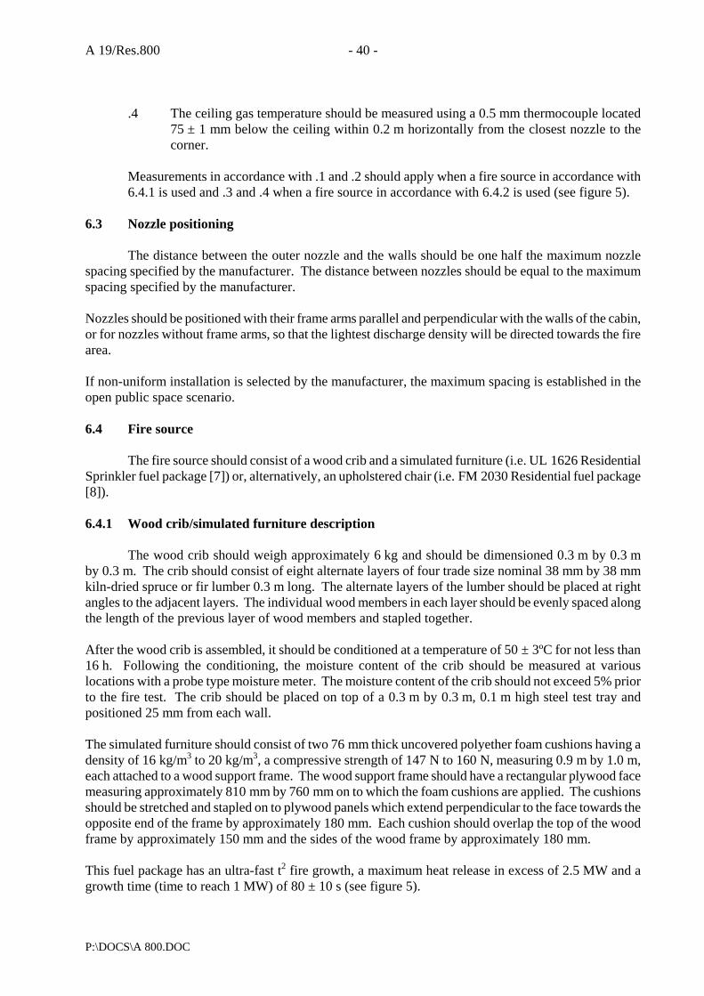
A 19/Res.800 - 40 -
P:\DOCS\A 800.DOC
.4 The ceiling gas temperature should be measured using a 0.5 mm thermocouple located
75 ± 1 mm below the ceiling within 0.2 m horizontally from the closest nozzle to the corner.
Measurements in accordance with .1 and .2 should apply when a fire source in accordance with 6.4.1 is used and .3 and .4 when a fire source in accordance with 6.4.2 is used (see figure 5).
6.3 Nozzle positioning
The distance between the outer nozzle and the walls should be one half the maximum nozzle spacing specified by the manufacturer. The distance between nozzles should be equal to the maximum spacing specified by the manufacturer. Nozzles should be positioned with their frame arms parallel and perpendicular with the walls of the cabin, or for nozzles without frame arms, so that the lightest discharge density will be directed towards the fire area. If non-uniform installation is selected by the manufacturer, the maximum spacing is established in the open public space scenario. 6.4 Fire source
The fire source should consist of a wood crib and a simulated furniture (i.e. UL 1626 Residential Sprinkler fuel package [7]) or, alternatively, an upholstered chair (i.e. FM 2030 Residential fuel package [8]). 6.4.1 Wood crib/simulated furniture description
The wood crib should weigh approximately 6 kg and should be dimensioned 0.3 m by 0.3 m by 0.3 m. The crib should consist of eight alternate layers of four trade size nominal 38 mm by 38 mm kiln-dried spruce or fir lumber 0.3 m long. The alternate layers of the lumber should be placed at right angles to the adjacent layers. The individual wood members in each layer should be evenly spaced along the length of the previous layer of wood members and stapled together. After the wood crib is assembled, it should be conditioned at a temperature of 50 ± 3ºC for not less than 16 h. Following the conditioning, the moisture content of the crib should be measured at various locations with a probe type moisture meter. The moisture content of the crib should not exceed 5% prior to the fire test. The crib should be placed on top of a 0.3 m by 0.3 m, 0.1 m high steel test tray and positioned 25 mm from each wall. The simulated furniture should consist of two 76 mm thick uncovered polyether foam cushions having a density of 16 kg/m3 to 20 kg/m3, a compressive strength of 147 N to 160 N, measuring 0.9 m by 1.0 m, each attached to a wood support frame. The wood support frame should have a rectangular plywood face measuring approximately 810 mm by 760 mm on to which the foam cushions are applied. The cushions should be stretched and stapled on to plywood panels which extend perpendicular to the face towards the opposite end of the frame by approximately 180 mm. Each cushion should overlap the top of the wood frame by approximately 150 mm and the sides of the wood frame by approximately 180 mm. This fuel package has an ultra-fast t2 fire growth, a maximum heat release in excess of 2.5 MW and a growth time (time to reach 1 MW) of 80 ± 10 s (see figure 5).

- 41 - A 19/Res.800
P:\DOCS\A 800.DOC
6.4.2 Upholstered chair description
The fuel package consists of the following items (see figure 6):
Item
Code
No. of units
Dimensions and description
Simulated sofa end
S
1
19 mm plywood structure, open top and bottom, 610 mm by 914 mm, 610 mm high
Chair (recliner)1
C
1
Custom-made reclining chair approximately 760 mm by 914 mm, 990 mm high. All new materials consisting of vinyl covering with cotton backing (4.54 kg); polyurethane foam (seat 2.27 kg, 127 mm thick); polyurethane (arms, 1.36 kg, 25 mm thick); pine structure; total weight 23.8 kg, built by Old Brussels of Sturbridge, Massachussetts
End table
E
1
Table top; 19 mm particle board, 660 mm by 495 mm; table legs are softwood, i.e. pine, fir, etc; 38 mm by 38 mm, 514 mm high
Curtains
CW
4
2 panels, rod pocket panels (1,016 mm by 1,829 mm), fabric blend: 50% polyester, 50% cotton
2 panels sheer rod pocket panels (1,016 mm by 1,829 mm), (100% polyester batiste)
1An equivalent chair may be specified as a fire source with maximum heat release rate of 1.5 MW, a Required Delivered
Density of 5 mm/min, and a growth time of (time to reach 1 MW assuming second power growth in time) of 75s -125 s. 6.5 Test method
The fire tests should be conducted for 10 min after the activation of the first nozzle, and any remaining fire should be extinguished manually. 6.5.1 Wood crib/simulated furniture
0.2 l of heptane should be placed on a 5 mm water base in the test tray positioned directly below the wood crib. Approximately 120 g total of excelsior (wood wool) should be pulled apart and loosely positioned on the floor with approximately 60 g adjacent to each section of the simulated furniture. The heptane should be ignited and 40 s later the excelsior should also be ignited. 6.5.2 Upholstered chair
Ignition should take place using a lighted match at the centre of two horizontal axially parallel and adjacent 0.3 m long cotton wicks, each 9.3 mm in diameter, saturated with 25 cl of ethyl alcohol. The wick should be positioned at the base of the chair as described in figure 6, within 2 min prior to ignition.

A 19/Res.800 - 42 -
P:\DOCS\A 800.DOC
6.6 Acceptance criteria
Based on the measurements, a maximum of 30 s average value should be calculated for each measuring point which forms the temperature acceptance criteria.
Max. 30 s average
ceiling material/surface temperature (oC)
Max. 30 s average ceiling
gas temperature (oC)
Fire source
As per 6.4.1
260
320
As per 6.4.2
260
320
7 PUBLIC SPACE FIRE TESTS 7.1 Test arrangements
The fire tests should be conducted in a well-vented building under a ceiling of at least 80 m2 in area with no dimension less than 8 m. There should be at least a 1 m space between the perimeters of the ceiling and any wall of the test building. The ceiling height should be set at 2.5 m and 5.0 m respectively. Two different tests should be conducted as per 7.1.1 and 7.1.2. 7.1.1 Open public space test
The fire source should be positioned under the centre of the open ceiling so that there is an unobstructed flow of gases across the ceiling. The ceiling should be constructed from a non-combustible material. 7.1.2 Corner public space test
The test should be conducted in a corner constructed by two at least 3.6 m wide, nominally 12 mm thick, non-combustible wall boards. Plywood panels should be placed on the walls. The panels should be approximately 3 mm thick. The ignition time of the panel should not be more than 35 s and the flame spread time at 350 mm position should not be more than 100 s measured in accordance with IMO resolution A.653(16). The ceiling should be covered, 3.6 m out from the corner, with cellulosic acoustical panels. The acoustical panels should be nominally 12-15 mm thick, and should not ignite when tested in accordance with IMO resolution A.653(16). 7.2 Instrumentation
During each fire test, the following temperatures should be measured using thermocouples with diameter not exceeding 0.5 mm.
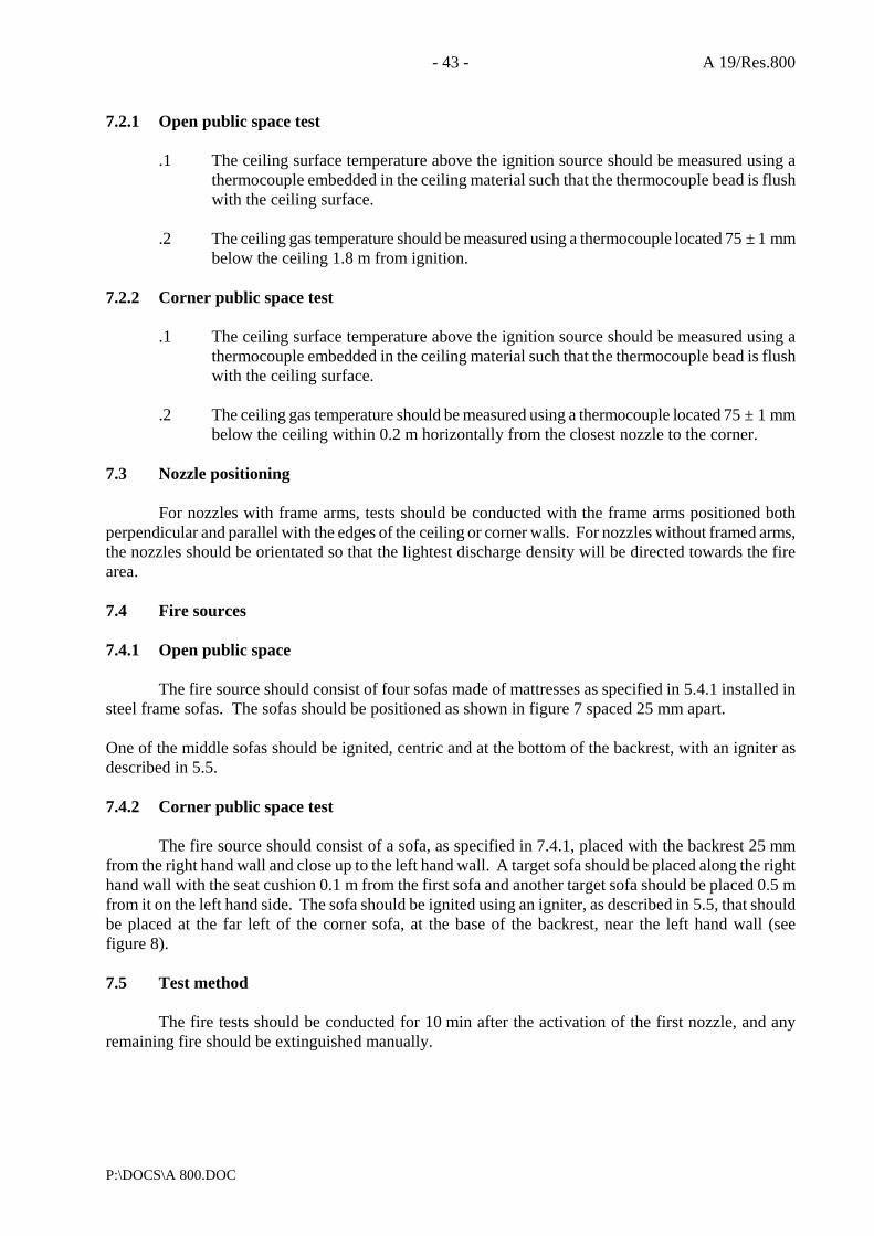
- 43 - A 19/Res.800
P:\DOCS\A 800.DOC
7.2.1 Open public space test
.1 The ceiling surface temperature above the ignition source should be measured using a thermocouple embedded in the ceiling material such that the thermocouple bead is flush with the ceiling surface.
.2 The ceiling gas temperature should be measured using a thermocouple located 75 ± 1 mm
below the ceiling 1.8 m from ignition. 7.2.2 Corner public space test
.1 The ceiling surface temperature above the ignition source should be measured using a thermocouple embedded in the ceiling material such that the thermocouple bead is flush with the ceiling surface.
.2 The ceiling gas temperature should be measured using a thermocouple located 75 ± 1 mm
below the ceiling within 0.2 m horizontally from the closest nozzle to the corner. 7.3 Nozzle positioning
For nozzles with frame arms, tests should be conducted with the frame arms positioned both perpendicular and parallel with the edges of the ceiling or corner walls. For nozzles without framed arms, the nozzles should be orientated so that the lightest discharge density will be directed towards the fire area. 7.4 Fire sources 7.4.1 Open public space
The fire source should consist of four sofas made of mattresses as specified in 5.4.1 installed in steel frame sofas. The sofas should be positioned as shown in figure 7 spaced 25 mm apart. One of the middle sofas should be ignited, centric and at the bottom of the backrest, with an igniter as described in 5.5. 7.4.2 Corner public space test
The fire source should consist of a sofa, as specified in 7.4.1, placed with the backrest 25 mm from the right hand wall and close up to the left hand wall. A target sofa should be placed along the right hand wall with the seat cushion 0.1 m from the first sofa and another target sofa should be placed 0.5 m from it on the left hand side. The sofa should be ignited using an igniter, as described in 5.5, that should be placed at the far left of the corner sofa, at the base of the backrest, near the left hand wall (see figure 8). 7.5 Test method
The fire tests should be conducted for 10 min after the activation of the first nozzle, and any remaining fire should be extinguished manually.
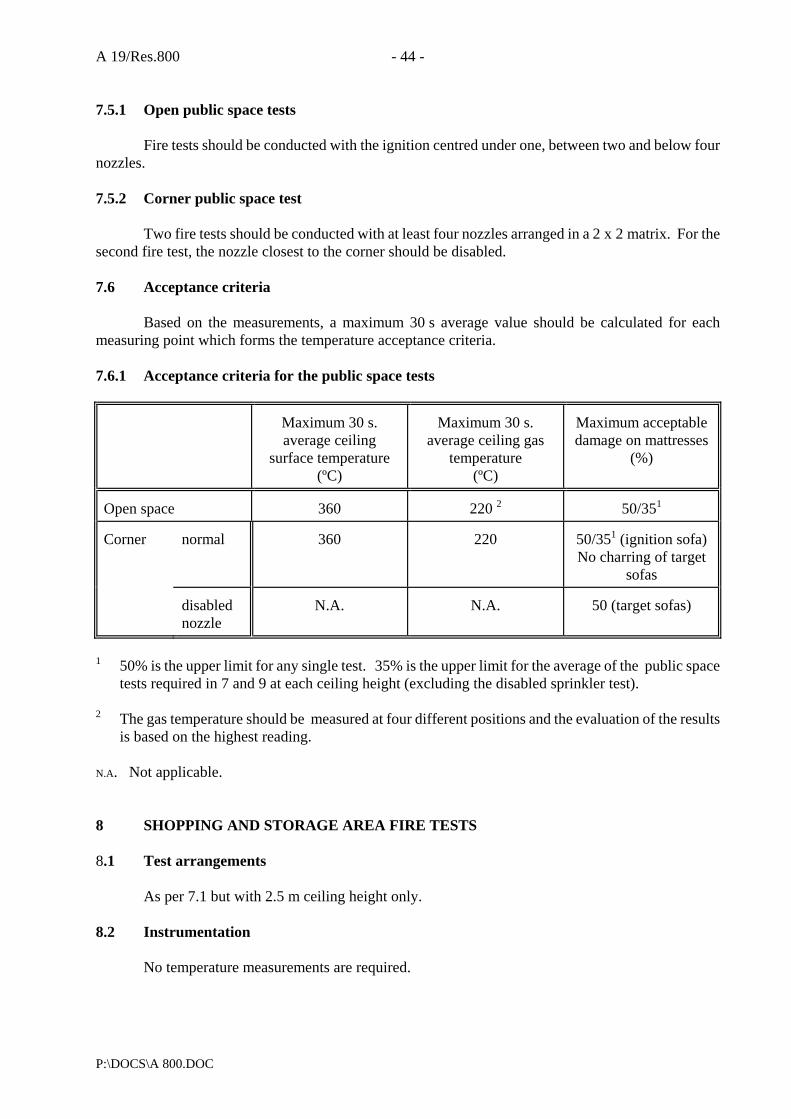
A 19/Res.800 - 44 -
P:\DOCS\A 800.DOC
7.5.1 Open public space tests
Fire tests should be conducted with the ignition centred under one, between two and below four nozzles. 7.5.2 Corner public space test
Two fire tests should be conducted with at least four nozzles arranged in a 2 x 2 matrix. For the second fire test, the nozzle closest to the corner should be disabled. 7.6 Acceptance criteria
Based on the measurements, a maximum 30 s average value should be calculated for each measuring point which forms the temperature acceptance criteria. 7.6.1 Acceptance criteria for the public space tests
Maximum 30 s. average ceiling
surface temperature (ºC)
Maximum 30 s.
average ceiling gas temperature
(ºC)
Maximum acceptable damage on mattresses
(%)
Open space
360
220 2
50/351
Corner
normal
360
220
50/351 (ignition sofa) No charring of target
sofas
disabled nozzle
N.A.
N.A.
50 (target sofas)
1 50% is the upper limit for any single test. 35% is the upper limit for the average of the public space
tests required in 7 and 9 at each ceiling height (excluding the disabled sprinkler test). 2 The gas temperature should be measured at four different positions and the evaluation of the results
is based on the highest reading. N.A. Not applicable. 8 SHOPPING AND STORAGE AREA FIRE TESTS 8.1 Test arrangements
As per 7.1 but with 2.5 m ceiling height only. 8.2 Instrumentation
No temperature measurements are required.

- 45 - A 19/Res.800
P:\DOCS\A 800.DOC
8.3 Nozzle positioning
As per 7.3. 8.4 Fire source
The fire source should consist of two central, 1.5 m high, solid piled stacks of cardboard boxes packed with polystyrene unexpanded plastic cups with a 0.3 m flue space. Each stack should be approximately 1.6 m long and 1.1 m to 1.2 m wide. A suitable plastic commodity is the FMRC standard plastic commodity [9]. Similar commodities might be used if they are designed in a similar way and are proven to have the same burning characteristics and suppressability. The fire source should be surrounded by six 1.5 m high solid piled stacks of empty cardboard boxes forming a target array to determine if the fire will jump the aisle. The boxes should be attached to each other, for example by staples, to prevent them from falling over (see figure 9). 8.5 Test method
Fire tests should be conducted with the ignition centred under one, between two and below four nozzles. Each fire should be ignited with a lighted match using two igniters as described in 5.5. The igniters should be located placed on the floor, each against the base of one of the two central stacks and ignited simultaneously. The fire tests should be conducted for 10 min after the activation of the first nozzle, and any remaining fire should be extinguished manually. 8.6 Acceptance criteria
.1 No ignition or charring of the target cartons is allowed.
.2 No more than 50% of the cartons filled with plastic cups should be consumed. 9 VENTILATION TEST
One corner public space test of 7 and the corridor space test which has given the worst result among those in 5.4.2 should be repeated with the ambient air having a minimum velocity of 0.3 m/s. The ambient air velocity in the public space tests should be measured 1 m above the floor and 1 m below the ceiling at a location 5 m out from the corner, midway between the enclosure walls. Air velocity in the corridor should be measured at the mid-height. 9.1 Acceptance criteria
The fire should not progress to the edge of the combustible wall or ceiling. 10 REFERENCED PUBLICATIONS [1] SOLAS, The International Convention for Safety of Life at Sea, International Maritime
Organization
A 19/Res.800 - 46 -
P:\DOCS\A 800.DOC
[2] Solomon, Robert E., Automatic Sprinkler Systems Handbook, National Fire Protection
Association, Batterymarch Park, Quincy, MA, USA, 5th edition, 1991 [3] ANSI/UL 723, Surface Burning Characteristics of Building Materials [4] ISO 6182/1 February 1994 edition [5] ISO 5660-1, Fire Tests - Reaction to fire - Rate of heat release from building products (Cone
calorimeter method), 1st edition, 1993 [6] Babrauskas, V. and Wetterlund, I., Instructions for Cone calorimeter testing of furniture samples,
CBUF Consortium, SP-AR 1993:65, Borås, Sweden, 1993 [7] Standard for Residential Sprinklers for Fire-Protection Service, UL 1626, Underwriters
Laboratories Inc., Northbrook, IL, USA, December 28, 1990 revision [8] Approval Standard for Residential and Limited Water Supply Automatic Sprinklers, Class 2030,
Factory Mutual Research Corporation, Norwood, MA, USA, January 27, 1993 [9] Chicarello, Peter, J., Troup, Joan, M.A., Fire Products Collector Test Procedure for Determining
the Commodity Classification of Ordinary Combustible Products, Factory Mutual Research Corporation, Norwood, MA, USA, August, 1990
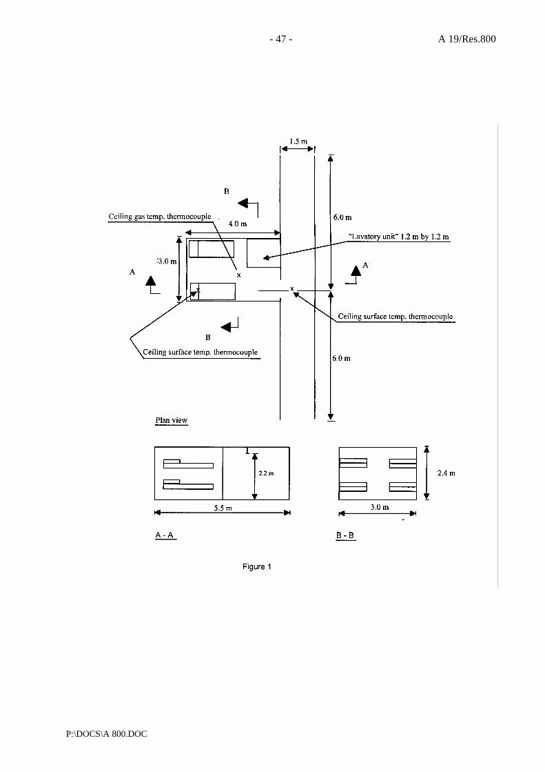
- 47 - A 19/Res.800
P:\DOCS\A 800.DOC
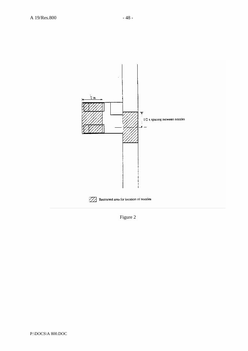
A 19/Res.800 - 48 -
P:\DOCS\A 800.DOC
Figure 2

- 49 - A 19/Res.800
P:\DOCS\A 800.DOC
Figure 3

A 19/Res.800 - 50 -
P:\DOCS\A 800.DOC
Figure 4
Stand
Igniter
8 piled mattresses0.4 m x 0.4 m
0.8 m
0.25 m
0.4 m

- 51 - A 19/Res.800
P:\DOCS\A 800.DOC

A 19/Res.800 - 52 -
P:\DOCS\A 800.DOC

- 53 - A 19/Res.800
P:\DOCS\A 800.DOC
Upholstered chair fuel package (dimensions in metres)
Ignition(210.3 Long cotton wicks
0.20
0.66
2.440.13
0.15
1.37
0.66
0.50
0.76
0.85
0.51
0.91
Combustiblepanelling Curtains
Recliner
Simulatedend table
Simulatedsofa end

A 19/Res.800 - 54 -
P:\DOCS\A 800.DOC
Figure 6
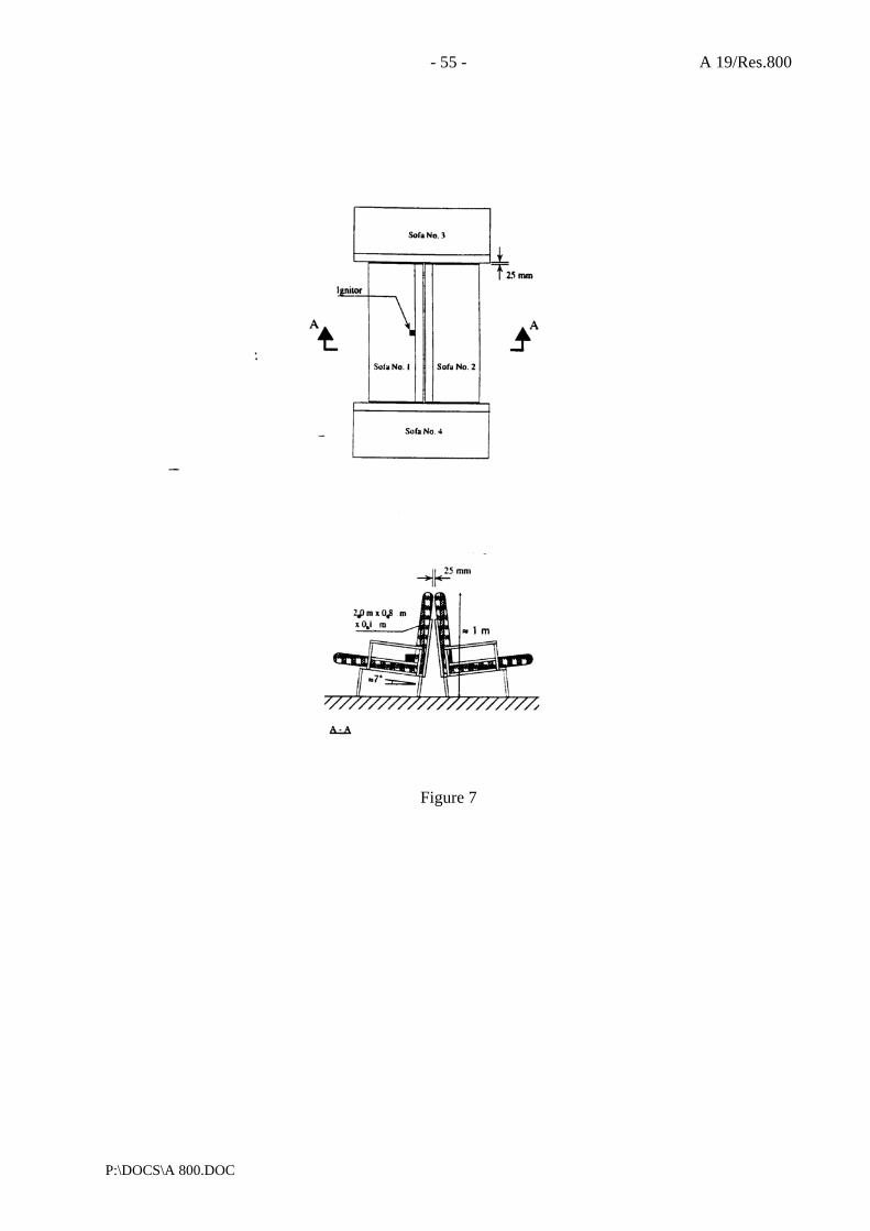
- 55 - A 19/Res.800
P:\DOCS\A 800.DOC
Figure 7

A 19/Res.800 - 56 -
P:\DOCS\A 800.DOC
Plywood panelling
Left hand,target sofa
Right hand,
target sofax
3.6 m
0.5 m
3.6 m
Ceiling surface temp. thermocouple
Ceiling gas temp. thermocouple
Acoustical ceiling tiles
x
Ignition point
Plan view
A - A
Figure 8
2.5/5.0 m
AA

- 57 - A 19/Res.800
P:\DOCS\A 800.DOC
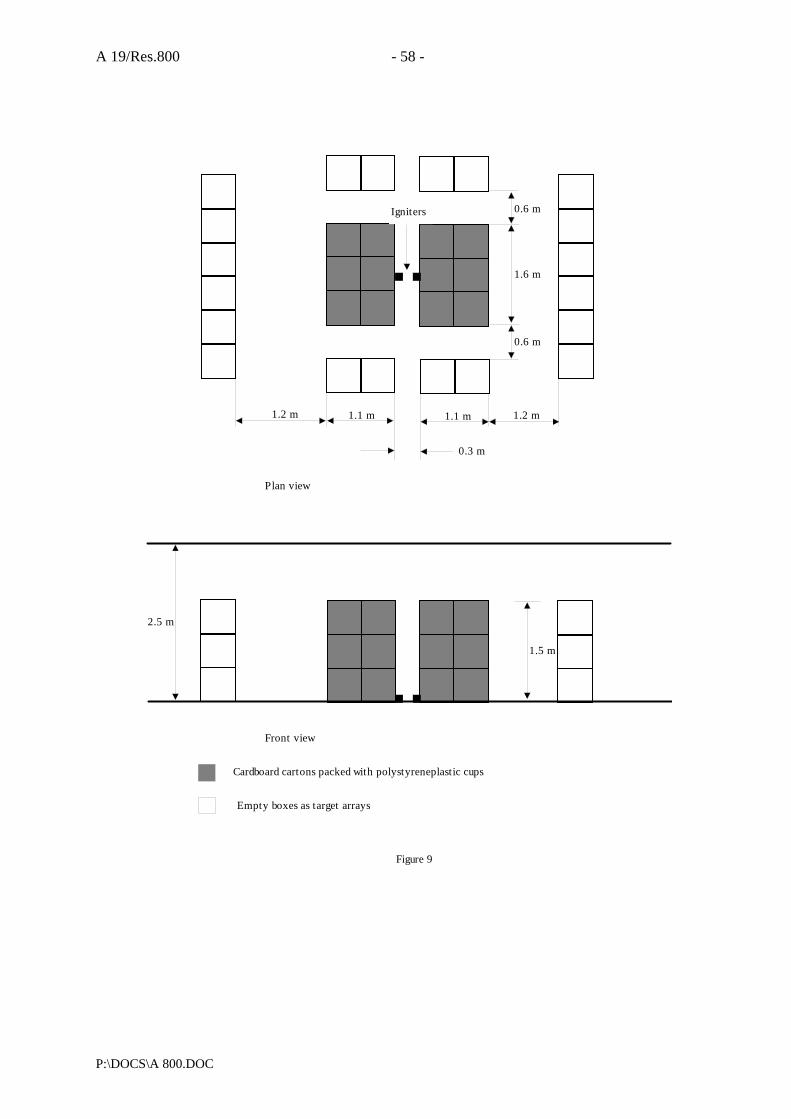
A 19/Res.800 - 58 -
P:\DOCS\A 800.DOC
2.5 m
1.5 m
1.2 m 1.1 m 1.1 m 1.2 m
0.6 m
1.6 m
0.6 mIgniters
0.3 m
Plan view
Front view
Cardboard cartons packed with polystyreneplastic cups
Empty boxes as target arrays
Figure 9

- 59 - A 19/Res.800
P:\DOCS\A 800.DOC
I:\ASSEMBLY\23\RES\951.DOC
For reasons of economy, this document is printed in a limited number. Delegates are kindly asked to bring their copies to meetings and not to request additional copies.
INTERNATIONAL MARITIME ORGANIZATION
IMO
E
ASSEMBLY 23rd session Agenda item 17
A 23/Res.951 25 February 2004 Original: ENGLISH
Resolution A.951(23)
Adopted on 5 December 2003 (Agenda item 17)
IMPROVED GUIDELINES FOR MARINE PORTABLE FIRE EXTINGUISHERS
THE ASSEMBLY,
RECALLING Article 15(j) of the Convention on the International Maritime Organization concerning the functions of the Assembly in relation to regulations and guidelines concerning maritime safety,
RECALLING ALSO that, by resolution A.602(15), it adopted the Revised Guidelines for Marine Portable Fire Extinguishers, to supplement the relevant requirements of chapter II-2 of the International Convention for the Safety of Life at Sea (SOLAS), 1974, as amended, as well as chapter V of the Torremolinos International Convention for the Safety of Fishing Vessels, 1977,
RECOGNIZING the need to further improve the said Revised Guidelines following the adoption of amendments to chapter II-2 of the 1974 SOLAS Convention and of the 1993 Torremolinos Protocol to the 1977 Torremolinos Convention referred to above, and in the light of the experience gained from the application of the Revised Guidelines,
HAVING CONSIDERED the recommendation made by the Maritime Safety Committee at its seventy-fifth session, 1. ADOPTS the Improved Guidelines for Marine Portable Fire Extinguishers, the text of which is set out in the Annex to the present resolution; 2. RECOMMENDS Governments concerned to apply the annexed Improved Guidelines in conjunction with the appropriate requirements of the international instruments referred to above; 3. AUTHORIZES the Maritime Safety Committee to keep the Improved Guidelines under review and amend or extend them as necessary; 4. REVOKES resolution A.602(15).

A 23/Res.951 - 2 -
I:\ASSEMBLY\23\RES\951.DOC
ANNEX
IMPROVED GUIDELINES FOR MARINE PORTABLE FIRE EXTINGUISHERS 1 Scope
These Guidelines have been developed to supplement the relevant requirements for marine portable fire extinguishers* of the International Convention for the Safety of Life at Sea 74, as amended, the International Code for Fire Safety Systems (FSS Code) and the 1993 Torremolinos Protocol relating to the Torremolinos International Convention for the Safety of Fishing Vessels, 1977. The Guidelines are offered to Administrations to assist them in determining appropriate design and construction parameters. The status of the Guidelines is advisory. Their content is based on current practices and does not exclude the use of designs and materials other than those indicated below. 2 Definitions 2.1 An extinguisher is an appliance containing an extinguishing medium, which can be expelled by the action of internal pressure and be directed into a fire. This pressure may be stored pressure or be obtained by release of gas from a cartridge. 2.2 A portable extinguisher is one, which is designed to be carried and operated by hand, and which in working order has a total weight of not more that 23 kg. 2.3 Extinguishing medium is the substance contained in the extinguisher which is discharged to cause extinction of fire. 2.4 Charge of an extinguisher is the mass or volume of the extinguishing medium contained in the extinguisher. The quantity of the charge of water or foam extinguishers is normally expressed in volume (litres) and that of other types of extinguishers in mass (kilograms). 3 Classification 3.1 Extinguishers are classified according to the type of extinguishing medium they contain. At present the types of extinguishers and the uses for which they are recommended are as follows:
Extinguishing medium Recommended for use on fires involving Water Water with additives
wood, paper, textiles and similar materials
Foam wood, paper, textiles and flammable liquids Dry powder/dry chemical (standard/ classes B, C )
flammable liquids, electrical equipment and flammable gases
Dry powder/dry chemical (multiple or general purpose/classes A, B, C)
wood, paper, textiles, flammable liquids, electrical equipment and flammable gases
Dry powder/dry chemical (metal) combustible metals Carbon dioxide flammable liquids and electrical equipment Wet chemical for class F or K cooking grease, fats or oil fires Clean agents**
* Wherever in the text of these Guidelines the word �portable extinguisher� appears it should be taken as meaning
�marine portable fire extinguisher�. ** Refer to the recommendations by the International Organization for Standardization, in particular Publication
ISO 7165:1999, Fire-fighting � Portable fire extinguishers � Performance and construction.

- 3 - A 23/Res.951
I:\ASSEMBLY\23\RES\951.DOC
3.2 A table is provided in the appendix which describes the general characteristics of each type of extinguisher. 4 Construction 4.1 The construction of an extinguisher should be designed and manufactured for simple and rapid operation, and ease of handling. 4.2 Extinguishers should be manufactured to a recognized national or international standard*, which includes a requirement that the body, and all other parts subject to internal pressure, be tested:
.1 to a pressure of 5.5 MPa or 2.7 times the normal working pressure, whichever is the higher, for extinguishers with a service pressure not exceeding 2.5 MPa; or
.2 in accordance with the recognized standard for extinguishers with a service
pressure exceeding 2.5 MPa. 4.3 In the design of components, selection of materials and determination of maximum filling ratios and densities, consideration should be given to the temperature extremes to which extinguishers may be exposed on board ships and operating temperature ranges specified in the recognized standards. 4.3 The materials of construction of exposed parts and adjoining dissimilar metals should be carefully selected to function properly in the marine environment. 5 Fire classifications 5.1 Fire classifications are generally indicated as A, B, C, D and F (or K). There are currently two standards, defining classes of fires according to the nature of the material undergoing combustion, as follows:
International Organization for Standardization (ISO standard 3941)*
National Fire Protection Association (NFPA 10)
Class A: Fires involving solid materials, usually of an organic nature, in which combustion normally takes place with the formation of glowing embers.
Class A: Fires in ordinary combustible materials such as wood, cloth, paper, rubber and many plastics.
Class B: Fires involving liquids or liquefiable solids.
Class B: Fires in flammable liquids, oils, greases, tars, oil base paints, lacquers and flammable gases.
Class C: Fires involving gases. Class C: Fires, which involve energized electrical equipment where the electrical non-conductivity of the extinguishing medium is of importance. (When electrical equipment is de-energized, extinguishers for class A or B fires may be used safely.)
Class D: Fires involving metals. Class D: Fires in combustible metals such as magnesium, titanium, zirconium, sodium, lithium and potassium.
Class F: Fires involving cooking oils. Class K: Fires involving cooking grease, fats and oils.
*Comite Europeen de Normalisation (CEN standard EN2) closely follows ISO standard 3941.
* Refer to the recommendations by the International Organization for Standardization, in particular Publication
ISO 7165:1999, Fire-fighting � Portable fire extinguishers � Performance and construction.

A 23/Res.951 - 4 -
I:\ASSEMBLY\23\RES\951.DOC
6 Test specifications
6.1 Construction, performance and fire-extinguishing test specifications should be to the satisfaction of the Administration, having due regard to an established international standard*. 7 Criteria for assessing compliance with chapter 4 of the FSS Code and
regulations V/20 and V/38 of the 1993 Torremolinos Protocol relating to the 1977 Torremolinos Convention
7.1 Chapter 4 of the FSS Code requires that extinguishers have a fire-extinguishing capability at least equivalent to that of a 9 L fluid extinguisher having a rating of 2A on class A fire which may be water or foam as required by the Administration. This equivalence may be demonstrated by fire test ratings determined according to an international, national or other recognized standard*. 7.2 The size and type of extinguishers should be dependent upon the potential fire hazards in the protected spaces while avoiding a multiplicity of types. Care should also be taken to ensure that the quantity of extinguishing medium released in small spaces does not endanger personnel. 8 Marking of extinguishers 8.1 Each extinguisher should be clearly marked with the following minimum information:
.1 name of the manufacturer; .2 types of fire and rating for which the extinguisher is suitable; .3 type and quantity of extinguishing medium; .4 approval details;
.5 instructions for use and recharge (it is recommended that operating instructions be
given in pictorial form, in addition to explanatory text in language understood by the likely user);
.6 year of manufacture;
.7 temperature range over which the extinguisher will operate satisfactorily; and
.8 test pressure.
9 Periodical inspections and maintenance 9.1 Extinguishers should be subject to periodical inspections in accordance with the manufacturer's instructions and serviced at intervals not exceeding one year.
* Refer to the recommendations by the International Organization for Standardization, in particular Publication
ISO 7165:1999, Fire-fighting � Portable fire extinguishers � Performance and construction.
- 5 - A 23/Res.951
I:\ASSEMBLY\23\RES\951.DOC
9.1.1 At least one extinguisher of each type manufactured in the same year and kept on board a ship should be test discharged at five yearly intervals (as part of a fire drill). 9.1.2 All extinguishers together with propellant cartridges should be hydraulically tested in accordance with the recognized standard or the manufacturer�s instruction at intervals not exceeding ten years. 9.1.3 Service and inspection should only be undertaken by, or under the supervision of, a person with demonstrable competence, based on the inspection guide in table 9.1.3. 9.2 Records of inspections should be maintained. The records should show the date of inspection, the type of maintenance carried out and whether or not a pressure test was performed. 9.3 Extinguishers should be provided with a visual indication of discharge. 9.4 Instructions for recharging extinguishers should be supplied by the manufacturer and be available for use on board.

A 23/Res.951 - 6 -
I:\ASSEMBLY\23\RES\951.DOC
ANNUAL INSPECTION Safety clip and indicating devices Check to see if the extinguisher may have been operated. Pressure indicating device Where fitted, check to see that the pressure is within limits.
Check that dust covers on pressure indicating devices and relief valves are in place.
External examination Inspect for corrosion, dents or damage which may affect the safe operation of the extinguisher.
Weight Weigh the extinguisher and check the mass compared to the fully charged extinguisher.
Hose and nozzle Check that hoses and nozzles are clear and undamaged. Operating instructions Check that they are in place and legible.
INSPECTION AT RECHARGE Water and foam charges Remove the charge to a clean container if to be reused and
check if it is still suitable for further use. Check any charge container.
Powder charges Examine the powder for reuse. Ensure that it is free flowing and that there is no evidence of caking lumps or foreign bodies.
Gas cartridge Examine for damage and corrosion. INSPECTION AT FIVE AND TEN YEAR INTERVALS
INSPECTION AFTER DISCHARGE TEST Air passages and operating mechanism Prove clear passage by blowing through vent holes and vent
devices in the cap. Check hose, nozzle strainer, discharge tube and breather valve, as applicable. Check the operating and discharge control. Clean and lubricate as required.
Operating mechanism Check that the safety pin is removable and that the lever is undamaged.
Gas cartridge Examine for damage and corrosion. Weigh the cartridge to ascertain that it is within prescribed limits.
O-rings washers and hose diaphragms Check O-rings and replace hose diaphragms if fitted. Water and foam bodies Inspect the interior. Check for corrosion and lining
deterioration. Check separate containers for leakage or damage.
Powder body Examine the body and check internally for corrosion and lining deterioration.
INSPECTION AFTER RECHARGE Water and foam Replace the charge in accordance with the manufacturers
instructions. Reassemble Reassemble the extinguisher in accordance with the
manufacturers instructions. Maintenance label Fill in entry on maintenance label, including full weight. Mounting of extinguishers Check the mounting bracket or stand. Report Complete a report on the state of maintenance of the
extinguisher.
Table 9.1.3 � Inspection guide

- 7 - A 23/Res.951
I:\ASSEMBLY\23\RES\951.DOC
APPENDIX
TYPES OF EXTINGUISHER
Extinguishing medium used:
Water Foam Powder Carbon dioxide
Clean agents
Water, with possible salts in solution
Water solution containing foam generating substances
Dry chemical Powders
Pressurized carbon dioxide
Expellant charge of the extinguisher (stored pressure or cartridge as indicated):
Carbon dioxide or other pressurized inert gases or compressed air (stored pressure or separate cartridge)
Carbon dioxide or other pressurized inert gases or compressed air (stored pressure or separate cartridge)
Carbon dioxide or other inert gases or dry air (stored pressure or separate cartridge)
The discharge of the extinguisher is achieved by:
Opening of the valve. Action of pressurized gas (opening of the cartridge)
Opening of the valve. Action of pressurized gas (opening of the cartridge)
Opening of the valve. Action of pressurized gas (opening of the cartridge)
Opening of the valve of the container constituting the extinguisher

A 23/Res.951 - 8 -
I:\ASSEMBLY\23\RES\951.DOC
TYPES OF EXTINGUISHER
Water Foam Powder Carbon dioxide Clean agents
The discharged extinguishing medium consists of: Water with possible salts in
solution Foam containing the gas used
Dry chemical powders and carbon dioxide or other gas
Carbon dioxide
The discharged extinguishing medium causes the extinction of the fire by:
Cooling of the burning materials. Water evaporation and consequent formation of a local atmosphere (water/steam) which isolates the burning products from the surrounding air
Formation of a foam layer which isolates the burning products from the surrounding air and cooling in the case of class A fires
Inhibition of the combustion process by the interrupting the chemical reaction. Some separation of burning materials from the surrounding air
Formation of a local inert atmosphere (carbon dioxide) which isolates the burning material from the surrounding air. Smothering and cooling action of carbon dioxide
The electrical resistance of the discharged extinguishing medium is:
Very low Very low
Varied Very high. Under intense heat some powders may be electrically conductive
Very high
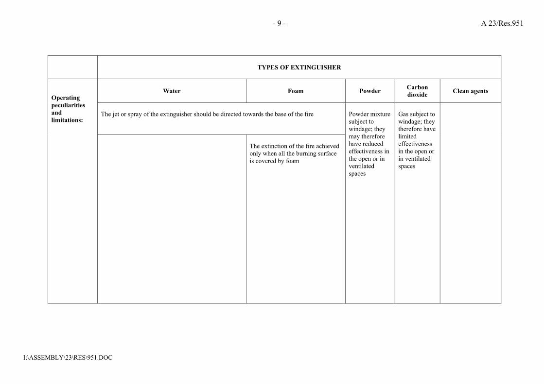
- 9 - A 23/Res.951
I:\ASSEMBLY\23\RES\951.DOC
TYPES OF EXTINGUISHER
Water Foam Powder Carbon dioxide Clean agents
The jet or spray of the extinguisher should be directed towards the base of the fire
Operating peculiarities and limitations:
The extinction of the fire achieved only when all the burning surface is covered by foam
Powder mixture subject to windage; they may therefore have reduced effectiveness in the open or in ventilated spaces
Gas subject to windage; they therefore have limited effectiveness in the open or in ventilated spaces
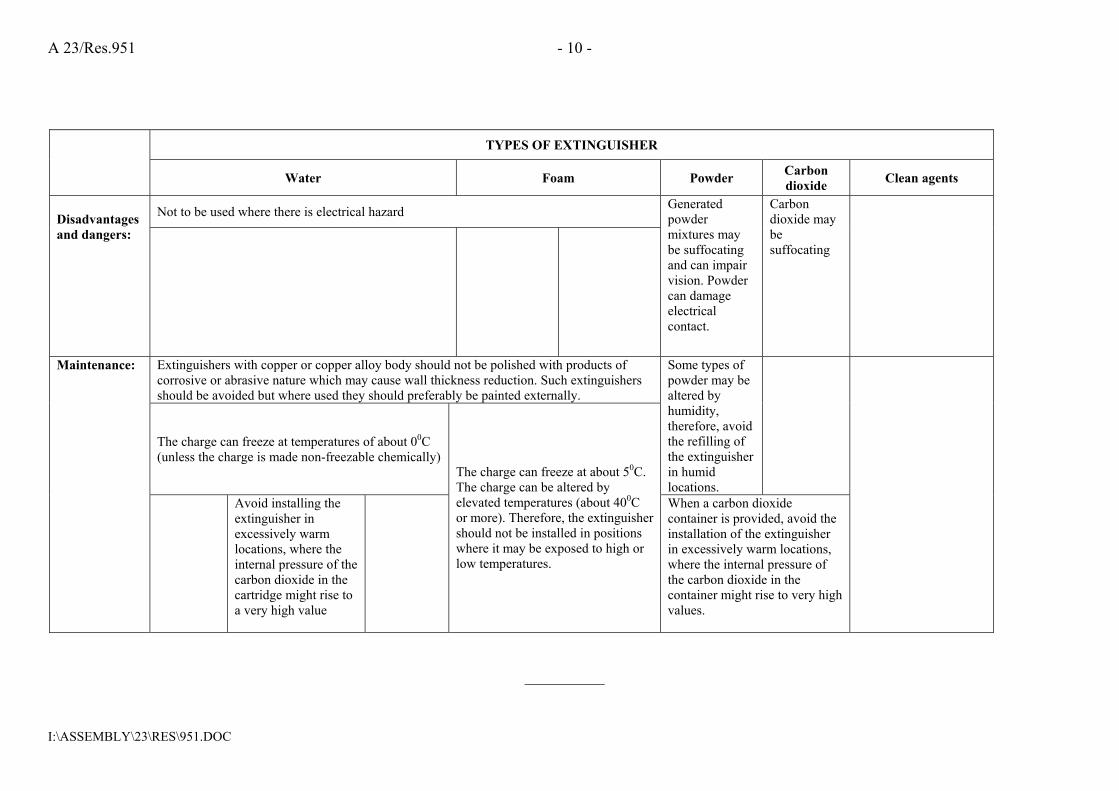
A 23/Res.951 - 10 -
I:\ASSEMBLY\23\RES\951.DOC
TYPES OF EXTINGUISHER
Water Foam Powder Carbon dioxide Clean agents
Not to be used where there is electrical hazard Disadvantages and dangers:
Generated powder mixtures may be suffocating and can impair vision. Powder can damage electrical contact.
Carbon dioxide may be suffocating
Extinguishers with copper or copper alloy body should not be polished with products of corrosive or abrasive nature which may cause wall thickness reduction. Such extinguishers should be avoided but where used they should preferably be painted externally.
The charge can freeze at temperatures of about 00C (unless the charge is made non-freezable chemically)
Some types of powder may be altered by humidity, therefore, avoid the refilling of the extinguisher in humid locations.
Maintenance:
Avoid installing the extinguisher in excessively warm locations, where the internal pressure of the carbon dioxide in the cartridge might rise to a very high value
The charge can freeze at about 50C. The charge can be altered by elevated temperatures (about 400C or more). Therefore, the extinguisher should not be installed in positions where it may be exposed to high or low temperatures.
When a carbon dioxide container is provided, avoid the installation of the extinguisher in excessively warm locations, where the internal pressure of the carbon dioxide in the container might rise to very high values.
__________

1 At its sixtieth session, the Maritime Safety Committee approved "Guidelines for the performance and testing criteria, and surveys of low-expansion foam concentrates for fixed fire-extinguishing systems".
2 Member Governments are recommended to ensure that tests for type approval and periodical control of the low-expansion foam concentrates are performed, in accordance with the attached guidelines.
1.1 - Application
These Guidelines apply to the foam concentrates for fixed low-expansion fire-extinguishing systems required by SOLAS 74(83) Reg. II-2/61 for oil tankers. These Guidelines also apply to foam concentrates for fixed low-expansion fire-extinguishing systems in machinery spaces according to SOLAS 74(83) Reg. II-2/8.
1.2 - Definitions
For the purpose of these Guidelines the following definitions apply.
The sampling method should ensure representative samples which should be stored in filled containers.
Title CIRCULAR / MSC/Circ.582
GUIDELINES FOR THE PERFORMANCE AND TESTING CRITERIA, AND SURVEYS OF LOW-EXPANSION FOAM CONCENTRATES FOR FIXED FIRE-EXTINGUISHING
SYSTEMS
ANNEX
GUIDELINES FOR THE PERFORMANCE AND TESTING CRITERIA, AND SURVEYS OF LOW-EXPANSION FOAM CONCENTRATES FOR FIXED FIRE-EXTINGUISHING
SYSTEMS
1 - GENERAL
(a) Foam (fire fighting) : an aggregate of air filled bubbles formed from an aqueous solution of a suitable foamconcentrate.
(b) Foam solution: a solution of foam concentrate and water.
(c) Foam concentrate: the liquid which, when mixed with water in the appropriate concentration, gives a foamsolution.
(d) Expansion ratio: the ratio of the volume of foam to the volume of foam solution from which it was made.
(e) Spreading coefficient: a measurement of the ability of one liquid to spontaneously spread across another.
(f) 25% (50%) drainage time: the time for 25% (50%) of the liquid content of a foam to drain out.
(g) Gentle application: application of foam to the surface of a liquid fuel via a backboard, tank wall or other surface.
(h) Sediment: insoluble particles in the foam concentrate.
2 - SAMPLING PROCEDURE

For foam concentrate type approval, the tests under paragraphs 3.1-3.11 should be performed. They should be carried out at laboratories acceptable to the Administration .
3.1 - Freezing and thawing
3.2 - Heat stability
An unopened 20 litre container (or other standard shipping container) as supplied by the manufacturer from a production batch should be maintained for 7 daysat 60℃, followed by one day at room temperature. Following this conditioning, the foam liquid after agitating/stirring will be subjected to the fire test as per 3.9, and comply with the requirements given in these guidelines.
3.3 - Sedimentation
The sample size should be :
-30 litres for type tests (see Section 3)
- 2 litres for periodical controls (see Section 4) .
3 - TESTS FOR TYPE APPROVAL OF FOAM CONCENTRATES
3.1.1 - Before and after temperature conditioning in accordance with 3.1.2, the foam concentrate should show no visual sign of stratification, non -homogeneity or sedimentation
3.1.2 - Freezing and thawing test
(a) Apparatus:
- freezing chamber, capable of achieving temperatures required as stated in (b.1);
- polyethylene tube, approximately 10 mm diameter, 400 mm long and sealed and weighted at one end, with suitable spacers attached. Figure 1 shows a typical form;
- 500 mL cylinder approximately 400 mm high and 65 mm diameter.
(b) Procedure:
(b .1) Set the temperature of the freezing chamber to a temperature which is 10°C below the freezing point of the sample measured in accordance with BS 5117: Section 1.3 (excluding 5.2 in the standard). To prevent the glass measuring cylinder from breaking, due to expansion of the foam concentrate on freezing, insert the tube into the measuring cylinder, sealed end downward, weighted if necessary to avoid notation, the spacers ensuring it remains approximately on the central axis of the cylinder. Place the sample in the cylinder in the chest, cool and maintain at the required temperature for 24 h. At the end of this period thaw the sample for not less than 24 h and not more than 96 h in an ambient temperature cf 20-25℃.
(b .2) Repeat (b.1) three times to give four cycles of freezing and thawing.
(b. 3) Examine the sample for stratification and ncn-homogeneity.
(b. 4) Condition the sample for 7 days at 60℃ followed by one day at room temperature.
3.3.1 - Any sediment in the concentrate prepared in accordance with Section 2 should be dispersible through a 180µm sieve, and the percentage volume of sediment should not be more than 0,25% when tested in accordance with 3.3.2.
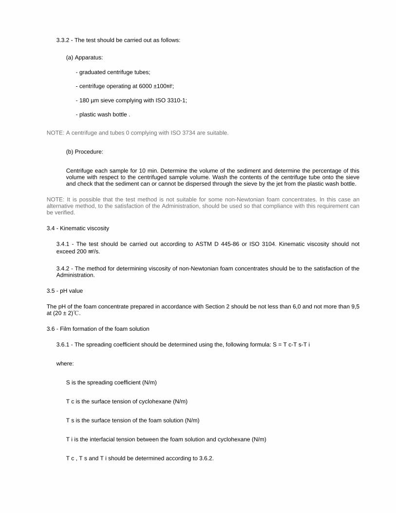
3.4 - Kinematic viscosity
3.5 - pH value
The pH of the foam concentrate prepared in accordance with Section 2 should be not less than 6,0 and not more than 9,5 at (20 ± 2)℃.
3.6 - Film formation of the foam solution
3.3.2 - The test should be carried out as follows:
(a) Apparatus:
- graduated centrifuge tubes;
- centrifuge operating at 6000 ±100㎨;
- 180 µm sieve complying with ISO 3310-1;
- plastic wash bottle .
NOTE: A centrifuge and tubes 0 complying with ISO 3734 are suitable.
(b) Procedure:
Centrifuge each sample for 10 min. Determine the volume of the sediment and determine the percentage of thisvolume with respect to the centrifuged sample volume. Wash the contents of the centrifuge tube onto the sieveand check that the sediment can or cannot be dispersed through the sieve by the jet from the plastic wash bottle.
NOTE: It is possible that the test method is not suitable for some non-Newtonian foam concentrates. In this case an alternative method, to the satisfaction of the Administration, should be used so that compliance with this requirement can be verified.
3.4.1 - The test should be carried out according to ASTM D 445-86 or ISO 3104. Kinematic viscosity should not exceed 200 ㎟/s.
3.4.2 - The method for determining viscosity of non-Newtonian foam concentrates should be to the satisfaction of the Administration.
3.6.1 - The spreading coefficient should be determined using the, following formula: S = T c-T s-T i
where:
S is the spreading coefficient (N/m)
T c is the surface tension of cyclohexane (N/m)
T s is the surface tension of the foam solution (N/m)
T i is the interfacial tension between the foam solution and cyclohexane (N/m)
T c , T s and T i should be determined according to 3.6.2.
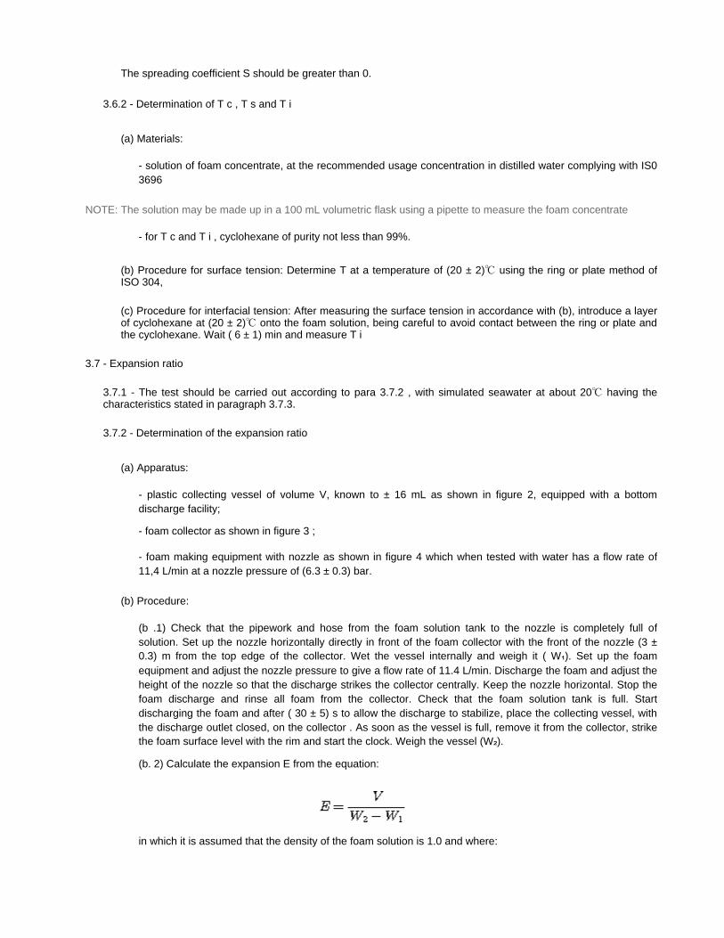
3.7 - Expansion ratio
The spreading coefficient S should be greater than 0.
3.6.2 - Determination of T c , T s and T i
(a) Materials:
- solution of foam concentrate, at the recommended usage concentration in distilled water complying with IS0 3696
NOTE: The solution may be made up in a 100 mL volumetric flask using a pipette to measure the foam concentrate
- for T c and T i , cyclohexane of purity not less than 99%.
(b) Procedure for surface tension: Determine T at a temperature of (20 ± 2)℃ using the ring or plate method of ISO 304,
(c) Procedure for interfacial tension: After measuring the surface tension in accordance with (b), introduce a layerof cyclohexane at (20 ± 2)℃ onto the foam solution, being careful to avoid contact between the ring or plate andthe cyclohexane. Wait ( 6 ± 1) min and measure T i
3.7.1 - The test should be carried out according to para 3.7.2 , with simulated seawater at about 20℃ having the characteristics stated in paragraph 3.7.3.
3.7.2 - Determination of the expansion ratio
(a) Apparatus:
- plastic collecting vessel of volume V, known to ± 16 mL as shown in figure 2, equipped with a bottom discharge facility;
- foam collector as shown in figure 3 ;
- foam making equipment with nozzle as shown in figure 4 which when tested with water has a flow rate of 11,4 L/min at a nozzle pressure of (6.3 ± 0.3) bar.
(b) Procedure:
(b .1) Check that the pipework and hose from the foam solution tank to the nozzle is completely full of solution. Set up the nozzle horizontally directly in front of the foam collector with the front of the nozzle (3 ±0.3) m from the top edge of the collector. Wet the vessel internally and weigh it ( W₁). Set up the foam equipment and adjust the nozzle pressure to give a flow rate of 11.4 L/min. Discharge the foam and adjust the height of the nozzle so that the discharge strikes the collector centrally. Keep the nozzle horizontal. Stop the foam discharge and rinse all foam from the collector. Check that the foam solution tank is full. Start discharging the foam and after ( 30 ± 5) s to allow the discharge to stabilize, place the collecting vessel, withthe discharge outlet closed, on the collector . As soon as the vessel is full, remove it from the collector, strike the foam surface level with the rim and start the clock. Weigh the vessel (W₂).
(b. 2) Calculate the expansion E from the equation:
in which it is assumed that the density of the foam solution is 1.0 and where:

3 .8 - Drainage time
3.9 - Fire tests
Fire tests should be carried out according to the following paragraphs 3.9.1 - 3.9.7.
V is the vessel volume (mL)
W₁ is the mass of the empty vessel (g)
W₂ is the mass of the full vessel (g).
(b .3) Open the drainage facility and collect the foam solution in the measuring cylinder to measure the 25% drainage time (see paragraph 3.8.1 hereinafter).
3.7.3 - Simulated sea water may be made up by dissolving
25,0 g Sodium chloride ( NaCl )
11,0 g Magnesium chloride (MgCI₂ 6H₂O)
1,6 g Calcium chloride (CaC1₂ 2H₂O)
4,0 g Sodium sulphate (Na₂ SO₄)
in each litre of potable water.
3.8.1 - The drainage time should be determined according to paragraph 3.7.2 (b.3) hereinabove, after having determined the expansion ratio.
3.8.2 - The test should be carried out with simulated seawater at about 20℃ having the characteristics stated in paragraph 3.7.3.
3.8.3 - Drainage time obtained with nozzles used on board should be consistent with the drainage time obtained withthe nozzles during the fire test .
NOTE: The fire tests of this Section 3.9 are more expensive and time consuming than the other tests of these guidelines. It is recommended that fire tests should be carried out at the end of the test programme, so as to avoid the expense of unnecessary testing of foam concentrates which do not comply in other respects .
3.9.1 - Environmental conditions
- Air temperature (15 ± 5)℃
- Maximum wind speed 3 m/s in proximity of the fire tray
NOTE: If necessary, some form of wind -screen may be used .
3.9.2 - Records
During the fire test, record the following:
- indoor or outdoor test
/1/2009
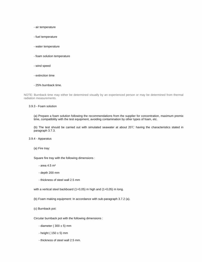
- air temperature
- fuel temperature
- water temperature
- foam solution temperature
- wind speed
- extinction time
- 25% burnback time.
NOTE: Burnback time may either be determined visually by an experienced person or may be determined from thermal radiation measurements.
3.9.3 - Foam solution
(a) Prepare a foam solution following the recommendations from the supplier for concentration, maximum premix time, compatibility with the test equipment, avoiding contamination by other types of foam, etc.
(b) The test should be carried out with simulated seawater at about 20℃ having the characteristics stated in paragraph 3.7.3.
3.9.4 - Apparatus
(a) Fire tray:
Square fire tray with the following dimensions :
- area 4.5 m²
- depth 200 mm
- thickness of steel wall 2.5 mm
with a vertical steel backboard (1+0,05) m high and (1+0,05) m long.
(b) Foam making equipment: In accordance with sub-paragraph 3.7.2 (a).
(c) Burnback pot:
Circular burnback pot with the following dimensions :
- diameter ( 300 ± 5) mm
- height ( 150 ± 5) mm
- thickness of steel wall 2.5 mm.
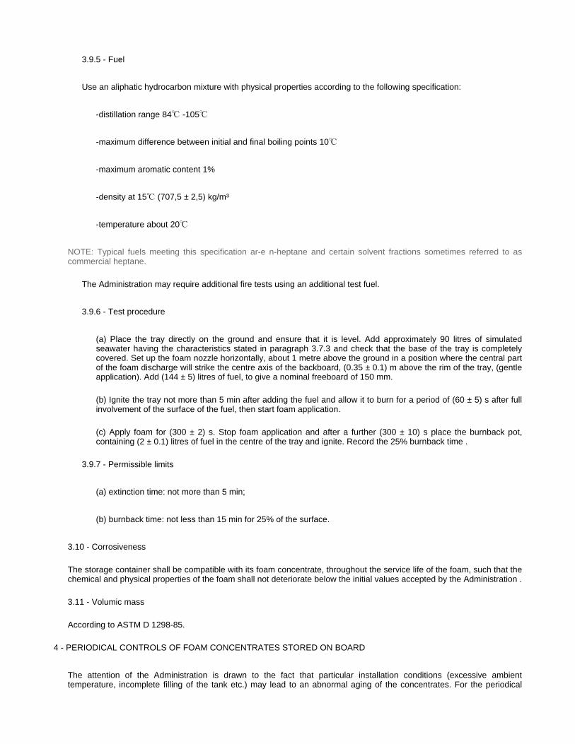
3.10 - Corrosiveness
The storage container shall be compatible with its foam concentrate, throughout the service life of the foam, such that the chemical and physical properties of the foam shall not deteriorate below the initial values accepted by the Administration .
3.11 - Volumic mass
According to ASTM D 1298-85.
The attention of the Administration is drawn to the fact that particular installation conditions (excessive ambient temperature, incomplete filling of the tank etc.) may lead to an abnormal aging of the concentrates. For the periodical
3.9.5 - Fuel
Use an aliphatic hydrocarbon mixture with physical properties according to the following specification:
-distillation range 84℃ -105℃
-maximum difference between initial and final boiling points 10℃
-maximum aromatic content 1%
-density at 15℃ (707,5 ± 2,5) kg/m³
-temperature about 20℃
NOTE: Typical fuels meeting this specification ar-e n-heptane and certain solvent fractions sometimes referred to ascommercial heptane.
The Administration may require additional fire tests using an additional test fuel.
3.9.6 - Test procedure
(a) Place the tray directly on the ground and ensure that it is level. Add approximately 90 litres of simulated seawater having the characteristics stated in paragraph 3.7.3 and check that the base of the tray is completely covered. Set up the foam nozzle horizontally, about 1 metre above the ground in a position where the central part of the foam discharge will strike the centre axis of the backboard, (0.35 ± 0.1) m above the rim of the tray, (gentle application). Add (144 ± 5) litres of fuel, to give a nominal freeboard of 150 mm.
(b) Ignite the tray not more than 5 min after adding the fuel and allow it to burn for a period of (60 ± 5) s after full involvement of the surface of the fuel, then start foam application.
(c) Apply foam for (300 ± 2) s. Stop foam application and after a further (300 ± 10) s place the burnback pot, containing (2 ± 0.1) litres of fuel in the centre of the tray and ignite. Record the 25% burnback time .
3.9.7 - Permissible limits
(a) extinction time: not more than 5 min;
(b) burnback time: not less than 15 min for 25% of the surface.
4 - PERIODICAL CONTROLS OF FOAM CONCENTRATES STORED ON BOARD

control of foam concentrate the tests under paragraphs 4.1 -4.5 should be performed. They should be carried out at laboratories acceptable to the Administration.
The deviations in the values obtained by these tests , in respect of those obtained during the type approval tests, should be within ranges acceptable to the Administration.
Tests under items 4.1, 4.3 and 4.4 should be carried out on samples maintained at 60℃ for 24 hours and subsequently cooled to the test temperature.
4.1 - Sedimentation
According to paragraph 3.3 above.
4.2 - pH value
According to paragraph 3.5 above .
4. 3 - Expansion ratio
According to paragraph 3.7 above .
4 .4 - Drainage time
According to paragraph 3.8 above .
4.5 - Volumic mass
According to paragraph 3.11 above.
The first periodical control of foam concentrates stored on board should be performed after a period of 3 years and, after that, every year.
A record of the age of the foam concentrates and of subsequent controls should be kept on board.
5 - INTERVALS OF PERIODICAL CONTROLS
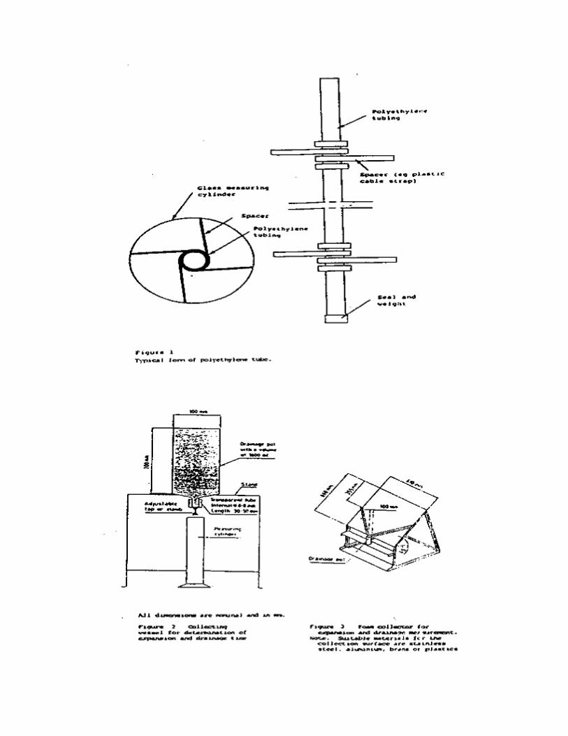

1 The Maritime Safety Committee, at its seventy-second session (17 to 26 May 2000), approved, as proposed by the Sub-Committee on Fire Protection at its forty-fourth session, a corrigendum to MSC/Circ.582 on Guidelines for the performance and testing criteria and surveys of low-expansion foam concentrates for fixed fire-extinguishing systems, as set out in the annex.
2 Member Governments are invited to take account of the annexed modifications to the aforementioned circular and bring them to the attention of all parties concerned.
1 In the title of MSC/Circ.582 replace the word "FROM" with "FOAM".
2 The following modifications are made to the text of the annex to MSC/Circ.582:
Title CIRCULAR / MSC/Circ.582c1
GUIDELINES FOR THE PERFORMANCE AND TESTING CRITERIA AND SURVEYS OF LOW-EXPANSION FOAM CONCENTRATES FOR FIXED FIRE-EXTINGUISHING
SYSTEMS
ANNEX
MODIFICATIONS TO THE GUIDELINES FOR THE PERFORMANCE AND TESTING CRITERIA AND SURVEYS OF LOW-EXPANSION FOAM CONCENTRATES FOR FIXED
FIRE-EXTINGUISHING SYSTEMS
(MSC/CIRC.582)
Corrigenda
.1 the existing text in paragraph 3.7.1 is replaced by the following new text:
"3.7.1 The test should be carried out according to paragraph 3.7.2 with simulated seawater at about 20℃ having the characteristics stated in paragraph 3.7.3.";
.2 in paragraph 3.7.2 (b.1), in the fourth sentence, the flow rate of "6 L/min" is replaced by "11.4 L/min";
.3 the existing text in paragraph 3.8.2 is replaced by the following new text:
"3.8.2 The test should be carried out with simulated seawater at about 20℃ having the characteristics stated in paragraph 3.7.3.";
.4 the existing text in paragraph 3.9.3 (b) is replaced by the following new text:
"(b) The test should be carried out with simulated seawater at about 20℃ having the characteristics stated in

________
paragraph 3.7.3."; and
.5 in paragraph 3.9.6 (a), the second sentence is replaced by the following:
"(a) Add approximately 90 L of simulated seawater having the characteristics stated in paragraph 3.7.3 and checkthat the base of the tray is completely covered."

I:\CIRC\MSC\668.DOC
INTERNATIONAL MARITIME ORGANIZATION 4 ALBERT EMBANKMENT LONDON SE1 7SR Telephone: 020 7735 7611 Fax: 020 7587 3210 Telex: 23588 IMOLDN G
IMO
E
Ref. T4/4.03 MSC/Circ.668 30 December 1994

MSC/Circ.668
I:\CIRC\MSC\668.DOC
ANNEX

MSC/Circ.668 ANNEX Page 2
I:\CIRC\MSC\668.DOC

MSC/Circ.668 ANNEX
Page 3
I:\CIRC\MSC\668.DOC

MSC/Circ.668 ANNEX Page 4
I:\CIRC\MSC\668.DOC
MSC/Circ.668 ANNEX
Page 5
I:\CIRC\MSC\668.DOC
MSC/Circ.668 ANNEX Page 6
I:\CIRC\MSC\668.DOC

MSC/Circ.668 ANNEX
Page 7
I:\CIRC\MSC\668.DOC

MSC/Circ.668 ANNEX Page 8
I:\CIRC\MSC\668.DOC
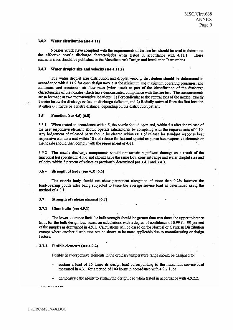
MSC/Circ.668 ANNEX
Page 9
I:\CIRC\MSC\668.DOC

MSC/Circ.668 ANNEX Page 10
I:\CIRC\MSC\668.DOC

MSC/Circ.668 ANNEX Page 11
I:\CIRC\MSC\668.DOC

MSC/Circ.668 ANNEX Page 12
I:\CIRC\MSC\668.DOC
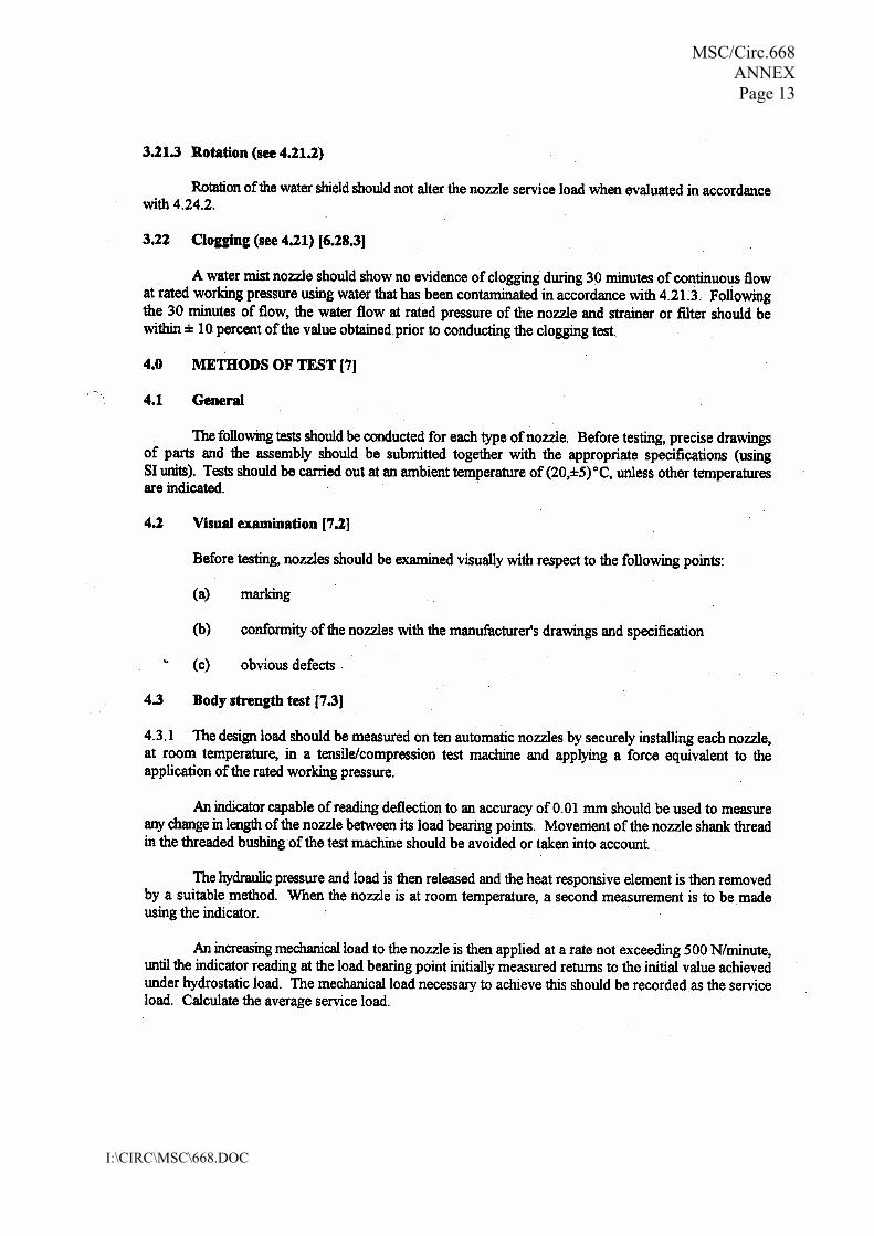
MSC/Circ.668 ANNEX Page 13
I:\CIRC\MSC\668.DOC

MSC/Circ.668 ANNEX Page 14
I:\CIRC\MSC\668.DOC

MSC/Circ.668 ANNEX Page 15
I:\CIRC\MSC\668.DOC

MSC/Circ.668 ANNEX Page 16
I:\CIRC\MSC\668.DOC
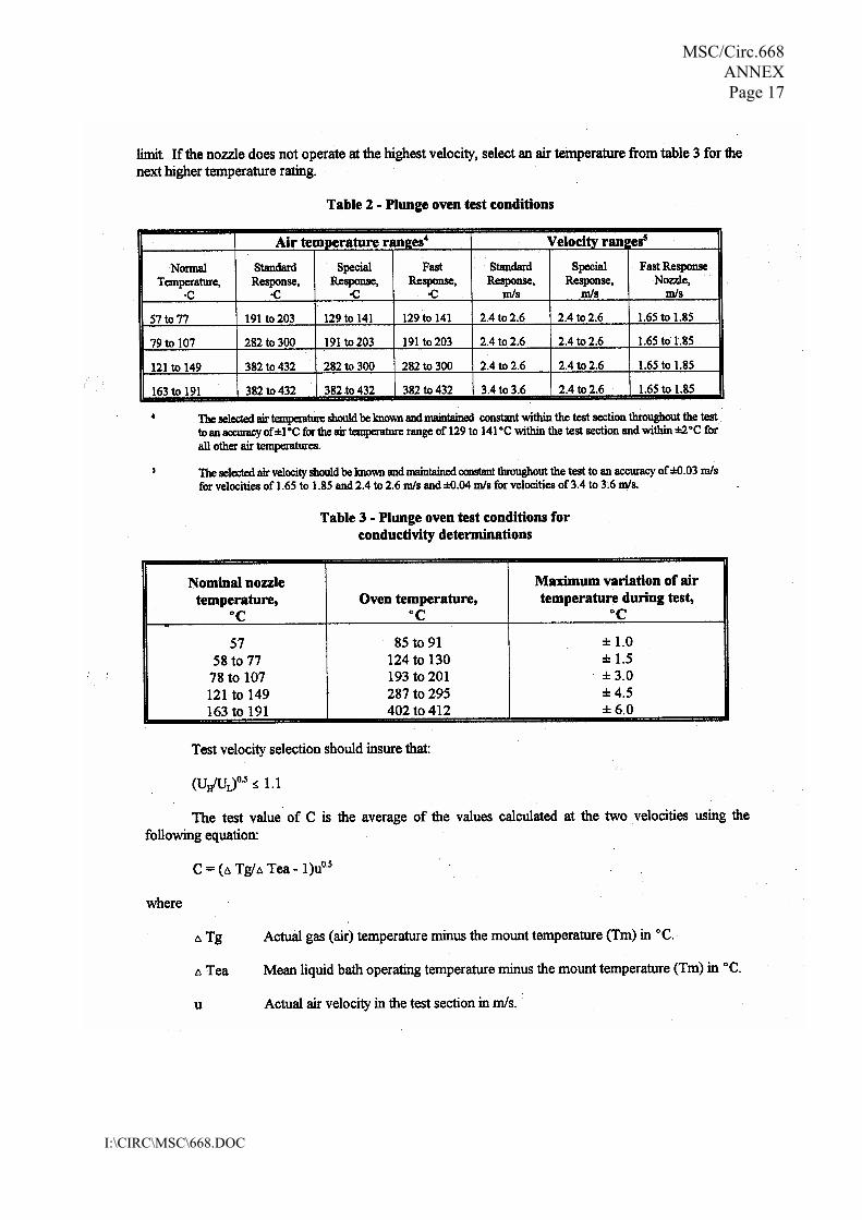
MSC/Circ.668 ANNEX Page 17
I:\CIRC\MSC\668.DOC

MSC/Circ.668 ANNEX Page 18
I:\CIRC\MSC\668.DOC
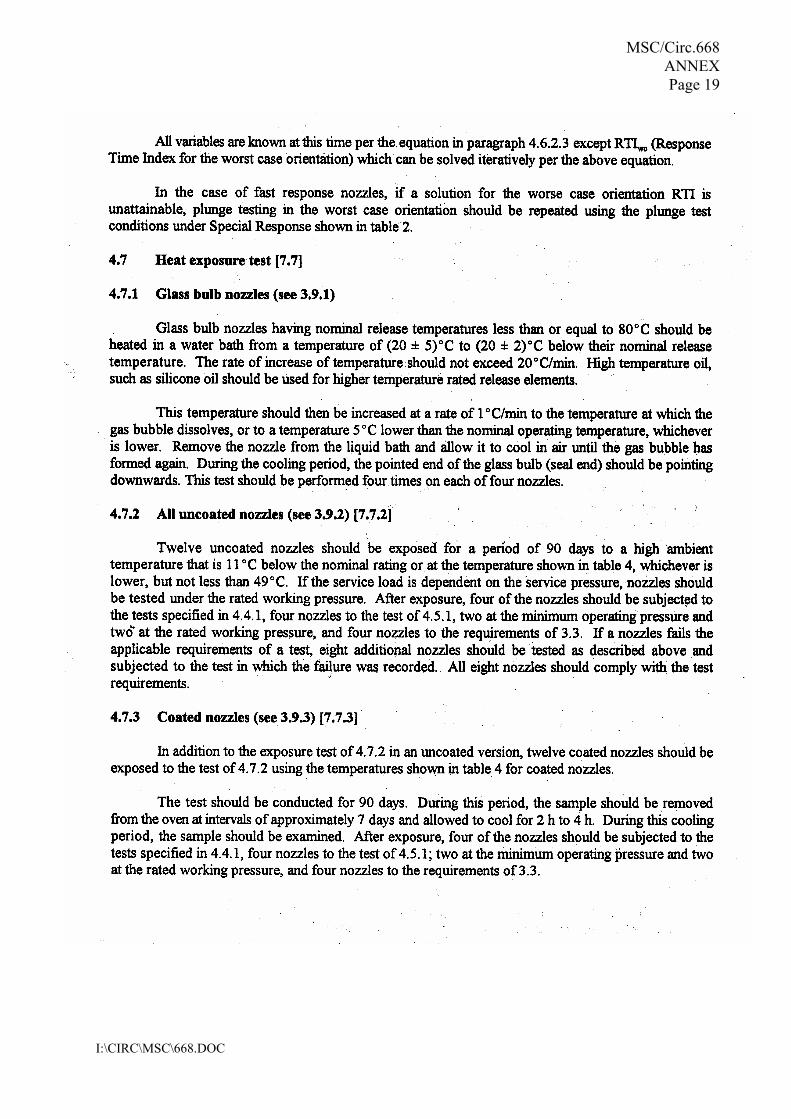
MSC/Circ.668 ANNEX Page 19
I:\CIRC\MSC\668.DOC
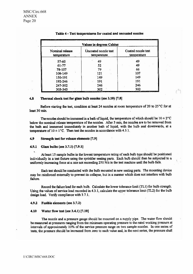
MSC/Circ.668 ANNEX Page 20
I:\CIRC\MSC\668.DOC

MSC/Circ.668 ANNEX Page 21
I:\CIRC\MSC\668.DOC

MSC/Circ.668 ANNEX Page 22
I:\CIRC\MSC\668.DOC

MSC/Circ.668 ANNEX Page 23
I:\CIRC\MSC\668.DOC

MSC/Circ.668 ANNEX Page 24
I:\CIRC\MSC\668.DOC

MSC/Circ.668 ANNEX Page 25
I:\CIRC\MSC\668.DOC

MSC/Circ.668 ANNEX Page 26
I:\CIRC\MSC\668.DOC

MSC/Circ.668 ANNEX Page 27
I:\CIRC\MSC\668.DOC

MSC/Circ.668 ANNEX Page 28
I:\CIRC\MSC\668.DOC

MSC/Circ.668 ANNEX Page 29
I:\CIRC\MSC\668.DOC

MSC/Circ.668 ANNEX Page 30
I:\CIRC\MSC\668.DOC

MSC/Circ.668 ANNEX Page 31
I:\CIRC\MSC\668.DOC

MSC/Circ.668 ANNEX Page 32
I:\CIRC\MSC\668.DOC

MSC/Circ.668 ANNEX Page 33
I:\CIRC\MSC\668.DOC

MSC/Circ.668 ANNEX Page 34
I:\CIRC\MSC\668.DOC

MSC/Circ.668 ANNEX Page 35
I:\CIRC\MSC\668.DOC

MSC/Circ.668 ANNEX Page 36
I:\CIRC\MSC\668.DOC

MSC/Circ.668 ANNEX Page 37
I:\CIRC\MSC\668.DOC
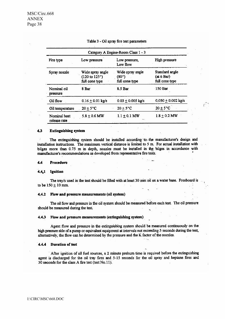
MSC/Circ.668 ANNEX Page 38
I:\CIRC\MSC\668.DOC
MSC/Circ.668 ANNEX Page 39
I:\CIRC\MSC\668.DOC

MSC/Circ.668 ANNEX Page 40
I:\CIRC\MSC\668.DOC
______________
1 The Maritime Safety Committee, at its sixty-fourth session (5 to 9 December 1994), approved Guidelines for the performance and testing criteria and surveys of high-expansion foam concentrates for fixed fire-extinguishing systems, given in annex.
2 Member Governments are recommended to ensure that tests for type approval and periodical control of the high-expansion foam concentrates are performed in accordance with the annexed guidelines.
1.1 Application
These guidelines apply to the foam concentrates for fixed high-expansion foam fire-extinguishing systems referred to in SOLAS regulation II-2/9.
1.2 Definitions
For the purpose of these Guidelines the following definitions apply.
The sampling method should ensure representative samples which should be stored in filled containers.
Title CIRCULAR / MSC/Circ.670
GUIDELINES FOR THE PERFORMANCE AND TESTING CRITERIA AND SURVEYS OF HIGH-EXPANSION FOAM CONCENTRATES FOR FIXED FIRE-EXTINGUISHING
SYSTEMS
ANNEX
GUIDELINES FOR THE PERFORMANCE AND TESTING CRITERIA AND SURVEYS OF HIGH-EXPANSION FOAM CONCENTRATES FOR FIXED FIRE-EXTINGUISHING
SYSTEMS
1 GENERAL
(a) Foam (fire fighting): an aggregate of air filled bubbles formed from an aqueous solution of a suitable foamconcentrate.
(b) Foam solution: a solution of foam concentrate and water.
(c) Foam concentrate: the liquid which, when mixed with water in the appropriate concentration, gives a foamsolution.
(d) Expansion ratio: the ratio of the volume of foam to the volume of foam solution from which it was made.
(e) Spreading coefficient: a measurement of the ability of one liquid to spontaneously spread across another.
(f) 25% (50%) drainage time: the time for 25% (50%) of the liquid content of a foam to drain out.
(g) Gentle application: application of foam to the surface of a liquid fuel via a backboard, tank wall or other surface.
(h) Sediment: insoluble particles in the foam concentrate.
2 SAMPLING PROCEDURE
The sample size should be:
For foam concentrate type approval, the tests under paragraphs 3.1 - 3.10 should be performed. They should be carried out at laboratories acceptable to the Administration.
3.1 Freezing and thawing
3.2 Heat stability
An unopened 20 litre container (or other standard shipping container) as supplied by the manufacturer from a production batch should be maintained for 7 days- at 60℃, followed by one day at room temperature. Following this conditioning, the foam liquid after agitating/stirring will be subjected to the fire test as per 3.8, and comply with the requirements given in these guidelines.
3.3 Sedimentation
- 30 litres for type tests (see Section 3)
- 2 litres for periodical controls (see Section 4).
3 TESTS FOR TYPE APPROVAL OF FOAM CONCENTRATES
3.1.1 Before and after temperature conditioning in accordance with 3.1.2, the foam concentrate should show novisual sign of stratification, non-homogeneity or sedimentation.
3.1.2 Freezing and thawing test
(a) Apparatus:
- freezing chamber, capable of achieving temperatures required as stated in (b.1);
- polyethylene tube, approximately 10 mm diameter, 400 mm long and sealed and weighted at one end, with suitable spacers attached. Figure 1 shows a typical form;
- 500 mL cylinder approximately 400 mm high and 65 mm diameter.
(b) Procedure:
(b.1) Set the temperature of the freezing chamber to a temperature which is 10 ℃ below the freezing point of the sample measured in accordance with BS 5117: Section 1.3 (excluding 5.2 in the standard). To prevent the glass measuring cylinder from breaking, due to expansion of the foam concentrate on freezing, insert the tube into the measuring cylinder, sealed end downward, weighted if necessary to avoid flotation, the spacers ensuring it remains approximately on the central axis of the cylinder. Place the sample in the cylinder in the chest, cool and maintain at the required temperature for 24 h. At the end of this period thaw the sample for not less than 24 h and not more than 96 h in an ambient temperature of 20-25 ℃.
(b.2) Repeat (b.1) three times to give four cycles of freezing and thawing.
(b.3) Examine the sample for stratification and non-homogeneity.
(b.4) Condition the sample for 7 days at 60 ℃ followed by one day at room temperature.
3.3.1 Any sediment in the concentrate prepared in accordance with Section 2 should be dispersible through a 180 ㎛sieve, and the percentage volume of sediment should not be more than 0,25% when tested in accordance with 3.3.2.
3.3.2 The test should be carried out as follows:
3.4 Kinematic viscosity
3.5 Ph value
The pH of the foam concentrate prepared in accordance with Section 2 should be not less than 6.0 and not more than 9.5 at 20 +/- 2) ℃.
3.6 Expansion ratio
(a) Apparatus:
- graduated centrifuge tubes;
- centrifuge operating at 6000 +/- 100 ㎨;
- 180 micro m sieve complying with ISO 3310-1;
- plastic wash bottle.
NOTE: A centrifuge and tubes complying with ISO 3734 are suitable.
(b) Procedure:
Centrifuge each sample for 10 min. Determine the volume of the sediment and determine the percentage of this volume with respect to the centrifuged sample volume. Wash the contents of the centrifuge tube onto the sieve and check that the sediment can or cannot be dispersed through the sieve by the jet from the plastic wash bottle.
NOTE: It is possible that the test method is not suitable for some non-Newtonian foam concentrates. In this case an alternative method, to the satisfaction of the Administration, should be used so that compliance with this requirement can be verified.
3.4.1 The test should be carried out according to ASTM D 445-86 or ISO 3104. Kinematic viscosity should not exceed 200 mm 2 /s.
3.4.2 The method for determining viscosity of non-Newtonian foam concentrates should be to the satisfaction of the Administration.
3.6.1 The test should be carried out according to paragraph 3.6.2, with sea water at about 20 ℃. Simulated sea water with the characteristics stated under 3.6.3 may be used. The expansion ratio obtained with the foam generators usedon board should be consistent with the expansion ratio obtained with the foam generators during the fire test.
3.6.2 Determination of the expansion ratio
(a) Apparatus:
- plastic collecting vessel of volume V, approximately 500 L and accurately known to +/- 5 L;
- high expansion foam-making equipment which when tested with water has a flow rate of 6.1 +/- 0.1 L/min at a nozzle pressure of (5.0 +/- 0.1) bar. An example for a suitable apparatus is given in document ISO 7203-2.
(b) Procedure:
(b.1) Wet the vessel internally and weigh it ( W 1). Set up the foam equipment and adjust the nozzle pressure to give a flow rate of 6.1 L/min. With the discharge facility closed, collect foam in the vessel. As soon as the vessel is full, stop collecting foam and strike the foam surface level with the rim. Weigh the vessel ( W 2).
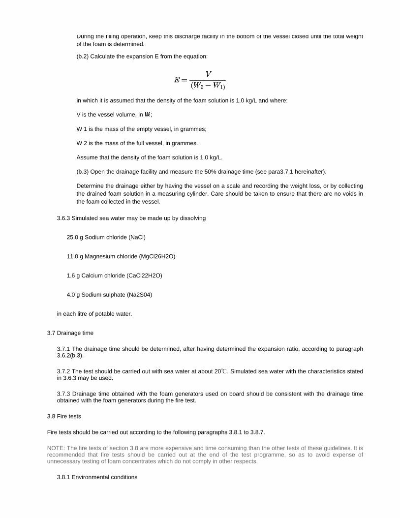
3.7 Drainage time
3.8 Fire tests
Fire tests should be carried out according to the following paragraphs 3.8.1 to 3.8.7.
During the filling operation, keep this discharge facility in the bottom of the vessel closed until the total weight of the foam is determined.
(b.2) Calculate the expansion E from the equation:
in which it is assumed that the density of the foam solution is 1.0 kg/L and where:
V is the vessel volume, in ㎖;
W 1 is the mass of the empty vessel, in grammes;
W 2 is the mass of the full vessel, in grammes.
Assume that the density of the foam solution is 1.0 kg/L.
(b.3) Open the drainage facility and measure the 50% drainage time (see para3.7.1 hereinafter).
Determine the drainage either by having the vessel on a scale and recording the weight loss, or by collecting the drained foam solution in a measuring cylinder. Care should be taken to ensure that there are no voids in the foam collected in the vessel.
3.6.3 Simulated sea water may be made up by dissolving
25.0 g Sodium chloride (NaCl)
11.0 g Magnesium chloride (MgCl26H2O)
1.6 g Calcium chloride (CaCl22H2O)
4.0 g Sodium sulphate (Na2S04)
in each litre of potable water.
3.7.1 The drainage time should be determined, after having determined the expansion ratio, according to paragraph3.6.2(b.3).
3.7.2 The test should be carried out with sea water at about 20℃. Simulated sea water with the characteristics stated in 3.6.3 may be used.
3.7.3 Drainage time obtained with the foam generators used on board should be consistent with the drainage timeobtained with the foam generators during the fire test.
NOTE: The fire tests of section 3.8 are more expensive and time consuming than the other tests of these guidelines. It is recommended that fire tests should be carried out at the end of the test programme, so as to avoid expense of unnecessary testing of foam concentrates which do not comply in other respects.
3.8.1 Environmental conditions

- Air temperature : (15 +/- 5) ℃
- Maximum wind speed : 3 m/s in proximity of the fire tray
3.8.2 Records
During the fire test, record the following:
- indoor or outdoor test
- air temperature
- fuel temperature
- water temperature0.
- foam solution temperature
- wind speed
- extinction time.
3.8.3 Foam solution
(a) Prepare a foam solution, following the recommendations from the supplier for concentration, maximum premix time, compatibility with the test equipment, avoiding contamination by other types of foam, etc.
(b) The test should be carried out with sea water at about 20 ℃. Simulated sea water with the characteristics stated in 3.6.3 may be used.
3.8.4 Apparatus
(a) Fire tray:
Circular fire tray of steel with dimensions as follows:
diameter at rim : (1,480 +/- 15) mm
depth: (150 +/- 10) mm
nominal thickness of steel wall: 2.5 mm
NOTE: The tray has an area of approximately 1.73 ㎡.
(b) Foam-making equipment:
In accordance with subparagraph 3.6.2(a).
3.9 Corrosiveness
The storage container shall be compatible with its foam concentrate, throughout the service life of the foam, such that the chemical and physical properties of the foam shall not deteriorate below the initial values accepted by the Administration.
3.10 Volumic mass
According to ASTM D 1298-85.
The attention of the Administration is drawn to the fact that particular installation conditions (excessive ambient
(c) Fire screens:
Fire screens of nominal 5 mm square metal mesh to form the nominal arrangement mentioned in subparagraph 3.8.6.
3.8.5 Fuel
Use an aliphatic hydrocarbon mixture with physical properties according to the following specification
- distillation range : 84 ℃-105 ℃
- maximum difference between initial and final boiling points : 10 ℃
- maximum aromatic content: 1%
- density at 15 ℃ : (707.5 +/- 2.5) ㎏/㎥
- temperature: about 20 ℃
NOTE: Typical fuels meeting this specification are n-heptane and certain solvent fractions sometimes referred to as commercial heptane.
The Administration may require additional fire tests using an additional test fuel.
3.8.6 Test procedure
(a) Place the tray directly on the ground and ensure that it is level. Add approximately 30 litres of sea water, or simulated sea water with the characteristics stated in 3.6.3, and (55 +/- 5) litres of fuel, to give a nominal freeboard of 100 mm.
(b) Place the net screens around the fire tray as shown in figure 2. Within 5 min ignite the fuel and allow it to burn for a period of not less than 45 s. Commence foam generation with the foam generator some distance from the fire. (60 +/- 5) s after full involvement move the foam generator to the opening between the net screen and applyfoam to the fire. Apply foam for a period of (120 +/- 2) s. Record the extinction time as the period from start of foam application to extinction.
3.8.7 Permissible limits
extinction time: not more than 120 s
4 PERIODICAL CONTROLS OF FOAM CONCENTRATES STORED ON BOARD

temperature, incomplete filling of the tank etc.) may lead to an abnormal aging of the concentrates. For the periodical control of foam concentrate the tests under paragraphs 4.1 - 4.5 should be performed. They should be carried out at laboratories acceptable to the Administration.
The deviations in the values obtained by these tests, in respect of those obtained during the type approval tests, should be within ranges acceptable to the Administration. Tests under items 4.1, 4.3 and 4.4 should be carried out on samples maintained at 60 ℃ or 24 hours and subsequently cooled to the test temperature.
4.1 Sedimentation
According to paragraph 3.3 above.
4.2 pH value
According to paragraph 3.5 above.
4.3 Expansion ratio
According to paragraph 3.7 above.
4.4 Drainage time
According to paragraph 3.8 above.
4.5 Volumic mass
According to paragraph 3.10 above.

The first periodical control of foam concentrates stored on board should be performed after a period of 3 years and, after that, every year.
A record of the age of the foam concentrates and of subsequent controls should be kept on board.
5 INTERVAL OF PERIODICAL CONTROLS

1 By resolution A.519(13) the Maritime Safety Committee was requested by the 1983 Assembly to finalize the Standards for devices to prevent the passage of flame into cargo tanks, the Committee was developing at the time, prior to the coming into force of the 1981 SOLAS amendments.
2 The Committee, at its forty-ninth session, (2 to 6 April 1984), adopted the standards so developed, which were attached to MSC/Circ.373.
3 The Committee agreed that the inert gas system was to be considered as equivalent to devices to prevent the passage of flame into cargo tanks only if vent outlets on ships fitted with inert gas systems were at least fitted with devices to prevent the passage of flame into cargo tanks, but that these devices need not comply with the test requirement for endurance burning. The Committee noted that, in the standards, emphasis was laid on compliance with test specifications rather than on construction. It was then understood that, in the case of a tanker fitted with an inert gas system, the provision of flashback would suffice and a well-designed and fitted flame screen could meet this criterion. In summary, if a flame screen met the standards, it would be accepted.
4 The Committee, at its fifty-fifth session, (11 to 22 April 1988), adopted amendments to the standards contained in MSC/Circ.373 and disseminated them as MSC/Circ.373/Rev.1.
5 The Committee, at its sixty-fourth session, (5 to 9 December 1994), recognizing the necessity to clarify some provisions in the revised standards, adopted further amendments thereto, which are incorporated in the test set out in the annex.
6 Member Governments are invited to give effect to the revised standards in conjunction with the application of regulation II-2/59 of the 1974 SOLAS Convention, as amended.
1.1 Purpose
1.2 Application
1.3 Definitions
2.1 Principles
2.2 Mechanical Design Standards
2.3 Performance Standards
2.4 Flame Screens
2.5 Sizing, location and installation of devices
3.1 Principles
Title CIRCULAR / MSC/Circ.677
Amendment Status Amended by MSC/Circ.1009
REVISED STANDARDS FOR THE DESIGN, TESTING AND LOCATING OF DEVICES TO PREVENT THE PASSAGE OF FLAME INTO CARGO TANKS IN TANKERS
CONTENTS
1 INTRODUCTION
2 STANDARDS
3 TYPE TEST PROCEDURES

3.2 Test procedures for flame arresters located at openings to the atmosphere
3.3 Test procedures for high velocity vents
3.4 Test rig and test procedures for detonation flame arresters located in-line
3.5 Operational test procedures
4.1 Marking of device
4.2 Laboratory report
4.3 Manufacturers' instruction manual
1.1 Purpose
The 1981 and the 1983 amendments to the International Convention for the Safety of Life at Sea, 1974 (SOLAS) include revised requirements for fire safety measures for tankers. Regulation II-2/59 of these amendments contains provisions concerning venting, purging, gas-freeing and ventilation. regulation II-2/59.1.5 states: "The venting system shall be provided with devices to prevent the passage of flame into the cargo tanks. The design, testing and locating of these devices shall comply with the requirements established by the Administration which shall contain at least the Standards adopted by the Organization."
1.2 Application
4 MISCELLANEOUS
1 INTRODUCTION
1.2.1 These Standards are intended to cover the design, testing, locating and maintenance of "devices to prevent thepassage of flame into cargo tanks" (hereafter called "devices") of tankers and combination carriers carrying crude oiland petroleum products having a flashpoint of 60 degrees C (closed cup) or less, and a Reid vapour pressure belowatmospheric pressure and other products having a similar fire hazard.
1.2.2 Oil tankers and combination carriers fitted with an inert gas system in accordance with regulation 62 should befitted with devices which comply with these Standards, except that the tests specified in 3.2.3 and 3.3.3.2 are notrequired. Such devices are only to be fitted at openings unless they are tested in accordance with 3.4.
1.2.3 These Standards are intended for devices protecting cargo tanks containing crude oil, petroleum products andflammable chemicals. In the case of the carriage of chemicals, the test media referred to in section 3 can be used.However, devices for chemical tankers dedicated to the carriage of products with MESG* less than 0.9 ㎜should be tested with appropriate media.
* Reference is made to IEC - Publication 79-1.
1.2.4 Devices should be tested and located in accordance with these Standards.
1.2.5 Devices are installed to protect:
.1 openings designed to relieve pressure or vacuum caused by thermal variations (regulation II- 2/59.1.2.1);
.2 openings designed to relieve pressure or vacuum during cargo loading, ballasting or during discharging (regulation II-2/59.1.2.2);
.3 outlets designed for gas-freeing (regulation II-2/59.2.2.3).
1.3 Definitions
For the purpose of these Standards, the following definitions are applicable.
2.1 Principles
1.2.6 Devices should not be capable of being bypassed or blocked open unless they are tested in the bypassed orblocked open position in accordance with section 3.
1.2.7 These Standards do not include consideration of sources of ignition such as lightning discharges sinceinsufficient information is available to formulate equipment recommendations. All cargo handling, tank cleaning andballasting operations should be suspended on the approach of an electrical storm.
1.2.8 These Standards are not intended to deal with the possibility of the passage of flame from one cargo tank toanother on tankers with common venting systems.
1.2.9 When outlet openings of gas-freeing systems on tankers not fitted with inert gas systems are required to beprotected with devices, they should comply with these Standards except that the tests specified in 3.2.3 and 3.3.3.2are not required.
1.2.10 Certain of the tests prescribed in section 3 of these Standards are potentially hazardous, but no attempt ismade in this circular to specify safety requirements for these tests.
1.3.1 "Flame arrester" is a device to prevent the passage of flame in accordance with a specified performancestandard. Its flame-arresting element is based on the principle of quenching.
1.3.2 "Flame screen" is a device utilizing wire mesh to prevent the passage of unconfined flames, in accordance witha specified performance standard.
1.3.3 "Flame speed" is the speed at which a flame propagates along a pipe or other system.
1.3.4 "Flashback" is the transmission of a flame through a device.
1.3.5 "High velocity vent" is a device to prevent the passage of flame, consisting of a mechanical valve which adjuststhe opening available for flow in accordance with the pressure at the inlet of the valve in such a way that the effluxvelocity cannot be less than 30 ㎧.
1.3.6 "Pressure/vacuum valve"* is a device designed to maintain pressure and vacuum in a closed container withinpreset limits.
* Pressure/vacuum valves are devices to prevent the passage of flame when designed and tested in accordance with these Standards.
2 STANDARDS
2.1.1 Depending on their service and location, devices are required to protect against the propagation of:
.1 moving flames; and/or
.2 stationary flames from pre-mixed gases; after ignition of gases resulting from any cause.
2.1.2 When flammable gases from outlets ignite, the following four situations may occur:
.1 At low gas velocities, the flame may:
2.2 Mechanical design standards
.1 flashback; or
.2 stabilize itself as if the outlet were a burner.
.2 At high velocities, the flame may:
.1 burn at a distance above the outlet; or
.2 be blown out.
2.1.3 In order to prevent the passage of flame into a cargo tank, devices must be capable of performing one or moreof the following functions:
.1 permitting the gas to pass through passages without flashback and without ignition of the gases on the protected side when the device is subjected to heating for a specified period;
.2 maintaining an efflux velocity in excess of the flame speed for the gas, irrespective of the geometric configuration of the device and without the ignition of gases on the protected side when the device is subjected to heating for a specified period; and
.3 preventing an influx of flame when conditions of vacuum occur within the cargo tanks.
2.2.1 The casing or housing of devices should meet similar standards of strength, heat resistance and corrosionresistance as the pipe to which they are attached.
2.2.2 The design of devices should allow for ease of inspection and removal of internal elements for replacement,cleaning or repair.
2.2.3 All flat joints of the housing should be machined true and should provide for a joint having an adequate metal-to-metal contact.
2.2.4 Flame arrester elements should fit in the housing in such a way that flame cannot pass between the elementand the housing.
2.2.5 Resilient seals may be installed only if their design is such that if the seals are partially or completely damagedor burned, the device is still capable of effectively preventing the passage of flame.
2.2.6 Devices should allow for efficient drainage of moisture without impairing their efficiency to prevent the passageof flame.
2.2.7 The casing and element and gasket materials should be capable of withstanding the highest pressure andtemperature to which the device may be exposed under both normal and specified fire test conditions.
2.2.8 End-of-line devices should be so constructed as to direct the efflux vertically upwards.
2.2.9 Fastenings essential to the operation of the device, i.e. screws, etc., should be protected against loosening.
2.2.10 Means should be provided to check that any valve lifts easily without remaining in the open position.
2.2.11 Devices in which the flame arresting effect is achieved by the valve function and which are not equipped withthe flame arrester elements (e.g. high velocity valves) must have a width of the contact area of the valve seat of atleast 5 ㎜.
2.2.12 Devices should be resistant to corrosion in accordance with 3.5.1.
2.3 Performance Standards
2.4 Flame screens
2.5 Sizing, location and installation of devices
2.2.13Elements, gaskets and seals should be of material resistant to both seawater and the cargoes carried.
2.2.14The casing or housing should be capable of passing a hydrostatic pressure test, as required in 3.5.2.
2.2.15In-line devices should be able to withstand, without damage or permanent deformation, the internal pressure resulting from detonation when tested in accordance with section 3.4.
2.2.16A flame arrester element should be designed to ensure quality control of manufacture to meet thecharacteristics of the prototype tested, in accordance with these Standards.
2.3.1 Devices should be tested in accordance with 3.5 and thereafter shown to meet the test requirements of 3.2 to3.4, as appropriate.
2.3.2 Performance characteristics, such as the flow rates under both positive and negative pressure, operatingsensitivity, flow resistance and velocity should be demonstrated by appropriate tests.
2.3.3 Devices should be designed and constructed to minimize the effect of fouling under normal operatingconditions. Instructions on how to determine when cleaning is required and the method of cleaning should beprovided for each device in the manufacturers' instruction manual.
2.3.4 Devices should be capable of operating in freezing conditions (such as may cause blockage by freezing cargovapours or by icing in bad weather) and if any device is provided with heating arrangements so that its surfacetemperature exceeds 85 degrees C, then it should be tested at the highest operating temperature.
2.3.5 Devices based upon maintaining a minimum velocity should be capable of opening in such a way that a velocityof 30 ㎧is immediately initiated, maintaining an efflux velocity of at least 30 ㎧at all flow rates and, when the gas flow is interrupted, be capable of closing in such a way that this minimum velocity is maintained until the valve is fullyclosed.
2.3.6 In the case of high velocity vents, the possibility of inadvertent detrimental hammering* leading to damageand/or failure should be considered, with a view to eliminating it.
* Hammering is rapid full stroke opening/closing, not intended by the manufacturer during normal operations.
2.4.1 Flame screens should be:
.1 designed in such a manner that they cannot be inserted improperly in the opening;
.2 securely fitted in openings so that flames cannot circumvent the screen;
.3 able to meet the requirements of these standards. For flame screens fitted at vacuum inlets through whichvapours cannot be vented the test specified in 3.2.3 need not be complied with; and
.4 be protected against mechanical damage.
2.5.1 For determining the size of devices to avoid inadmissible pressure or vacuum in cargo tanks during loading ordischarging, calculations of pressure losses should be carried out. The following parameters should be taken intoaccount:

3.1 Principles
.1 loading/discharge rates;
.2 gas evolution;
.3 pressure loss across devices, taking into account the resistance coefficient;
.4 pressure loss in the vent piping system;
.5 pressure at which the vent opens if a high velocity valve is used;
.6 density of the saturated vapour/air mixture; and
.7 to compensate for possible fouling of a flame arrester, 70% of its rated performance is to be used in thepressure drop calculation of the installation.
2.5.2 Devices should be located at the outlets to atmosphere unless tested and approved for in-line installation. Devices for in-line installation may not be fitted at the outlets to atmosphere unless they have also been tested and approved for that position.
2.5.3 End of line devices which are intended for exclusive use at openings of inerted cargo tanks need not be testedagainst endurance burning as specified in 3.2.3.
2.5.4 Where end-of-line devices are fitted with cowls, weather hoods and deflectors, etc., these attachments shouldbe fitted for the tests described in 3.2.
2.5.5 Where detonation flame arresters are installed, as in-line devices venting to atmosphere, they should be located at a sufficient distance from the open end of the pipeline so as to preclude the possibility of a stationary flame restingon the arrester.
2.5.6 When venting to atmosphere is not performed through an end-of-line device according to 2.5.4, or a detonation flame arrester according to 2.5.5, the in-line device has to be specifically tested with the inclusion of all pipes, tees, bends, cowls, weather hoods, etc., which may be fitted between the device and atmosphere. The testing shouldconsist of the flashback test of 3.2.2 and, if for the given installation it is possible for a stationary flame to rest on thedevice, the testing should also include the endurance burning test of 3.2.3.
2.5.7 Means should be provided to enable personnel to reach devices situated more than 2 m above deck to facilitatemaintenance, repair and inspection.
3 TYPE TEST PROCEDURES
3.1.1 Tests should be conducted by a laboratory acceptable to the Administration.
3.1.2 Each size of each model should be submitted for type testing. However, for flame arresters testing may belimited to the smallest and the largest sizes and one additional size in between to be chosen by the Administration.Devices should have the same dimensions and most unfavourable clearances expected in the production model. If atest device is modified during the test programme, the testing should be started over again.
3.1.3 Tests described in this section using gasoline vapours (a non-leaded petroleum distillate consisting essentially of aliphatic hydrocarbon compounds with a boiling range approximating 65 degrees C/ 75 degrees C), technicalhexane vapours, or technical propane, as appropriate, and referred to in this section, are suitable for all devicesprotecting tanks containing a flammable atmosphere of the cargoes referred to in 1.2.1. This does not preclude theuse of gasoline vapours or technical hexane vapours for all tests referred to in this section.
3.1.4 After the relevant tests, the device should not show mechanical damage that affects its original performance.

3.2 Test procedures for flame arresters located at openings to the atmosphere
3.1.5 Before the tests the following equipment as appropriate should be properly calibrated:
.1 gas concentration meters;
.2 thermometers;
.3 flow meters;
.4 pressure meters; and
.5 time recording devices.
3.1.6 The following characteristics should be recorded, as appropriate, throughout the tests:
.1 concentration of fuel in the gas mixture;
.2 temperature of the test gas mixture at inflow of the device; and
.3 flow rates of the test gas mixtures when applicable.
3.1.7 Flame passage should be observed by recording, e.g., temperature, pressure, or light emission by suitablesensors on the protected side of the device; alternatively, flame passage may be recorded on video tape.
3.2.1 The test rig should consist of an apparatus producing an explosive mixture, a small tank with a diaphragm, aflanged prototype of the flame arrester, a plastic bag* and a firing source in three positions (see appendix 1).** Othertest rigs may be used, provided the tests referred to in this section are achieved to the satisfaction of theAdministration.
* The dimensions of the plastic bag are dependent on those of the flame arrester, but for the flame arresters normally used on tankers, the plastic bag may have a circumference of 2 m, a length of 2.5 m and awall thickness of 0.05 m.
** In order to avoid remnants of the plastic bag from falling back on to the device being tested after ignition of the fuel/air mixture, it may be useful to mount a coarse wire frame across the device within the plastic bag. The frame should be so constructed as not to interfere with the test result.
3.2.2 A flashback test should be carried out as follows:
.1 The tank, flame arrester assembly and the plastic bag* enveloping the prototype flame arrester should be filled so that this volume contains the most easily ignitable propane/air mixture.*** The concentration of the mixture should be verified by appropriate testing of the gas composition in the plastic bag. Where devices referred to in 2.5.6 are tested, the plastic bag should be fitted at the outlet to atmosphere. Three ignition sources should be installed along the axis of the bag, one close to the flame arrester, another as far away as possible therefrom, and the third at the midpoint between these two. These three sources should be fired in succession, twice in each of the three positions. The temperature of the test gas should be within the range of 15 degrees C to 40 degrees C.
*** Reference is made to IEC Publication 79-1
.2 If a flashback occurs, the tank diaphragm will burst and this will be audible and visible to the operator by the emission of a flame. Flame, heat and pressure sensors may be used as an alternative to a bursting diaphragm.

3.3 Test procedures for high velocity vents
3.2.3 An endurance burning test should be carried out, in addition to the flashback test, for flame arresters at outletswhere flows of explosive vapour are foreseeable:
.1 The test rig as referred to in 3.2.1 may be used, without the plastic bag. The flame arrester should be soinstalled that the mixture emission is vertical. In this position the mixture should be ignited. Where devicesreferred to in 2.5.6 are tested, the flame arrester should be so installed as to reflect its final orientation.
.2 Endurance burning should be achieved by using the most easily ignitable gasoline vapour/air mixture or themost easily ignitable technical hexane vapour/air mixture with the aid of a continuously operated pilot flame or acontinuously operated spark igniter at the outlet. The test gas should be introduced upstream of the tank shown inappendix 2. Maintaining the concentration of the mixture as specified above, by varying the flow rate, the flamearrester should be heated until the highest obtainable temperature on the cargo tank side of the arrester isreached. Temperatures should be measured, for example, at the protected side of the flame quenching matrix ofthe arrester (or at the seat of the valve in case of testing high velocity vents according to 3.3). The highestobtainable temperature may be considered to have been reached when the rate of rise of temperature does notexceed 0.5 degrees C per minute over a ten-minute period. This temperature should be maintained for a period often minutes, after which the flow should be stopped and the conditions observed. The temperature of the test gasshould be within the range of 15 degrees C to 40 degrees C.
If no temperature rise occurs at all: inspect the arrester for a more adequate position of the temperature sensor,taking account of the visually registered position of the stabilized flame during the first test sequence. Positions whichrequire the drilling of small holes into fixed parts of the arrester have to be taken into account. If all this is notsuccessful, affix the temperature sensor at the unprotected side of the arrester in a position near to the stabilizedflame. If difficulties arise in establishing stationary temperature conditions (at elevated temperatures), the followingcriteria should apply: using the flow rate which produced the maximum temperature during the foregoing testsequence, endurance burning should be continued for a period of two hours from the time the above-mentioned flow rate has been established. After that period the flow should be stopped and the conditions observed. Flashbackshould not occur during this test.
3.2.4 When a pressure or/and vacuum valve is integrated to a flame arresting device, the flashback test has to beperformed with the pressure or/and vacuum valve blocked open. If there are no additional flame quenching elementsintegrated in a pressure valve, this valve has to be considered and tested as a high velocity vent valve according toparagraph 3.3.
3.3.1 The test rig should be capable of producing the required volume flow rate. In appendices 2 and 3, drawings ofsuitable test rigs are shown. Other test rigs may be used, provided the tests are achieved to the satisfaction of theAdministration.
3.3.2 A flow condition test should be carried out with high velocity vents using compressed air or gas at agreed flowrates. The following should be recorded:
.1 The flow rate. Where air or a gas other than vapours of cargoes with which the vent is to be used is employedin the test, the flow rates achieved should be corrected to reflect the vapour density of such cargoes.
.2 The pressure before the vent opens. The pressure in the test tank on which the device is located should notrise at a rate greater than 0.01 N/㎟/min.
.3 The pressure at which the vent opens.
.4 The pressure at which the vent closes
.5 The efflux velocity at the outlet which should not be less than 30 ㎧at any time when the valve is open.
3.3.3 The following fire safety tests should be conducted while adhering to 2.3.6 using a mixture of gasoline vapourand air or technical hexane vapour and air, which produces the most easily ignitable mixture at the point of ignition.This mixture should be ignited with the aid of a permanent pilot flame or a spark igniter at the outlet:
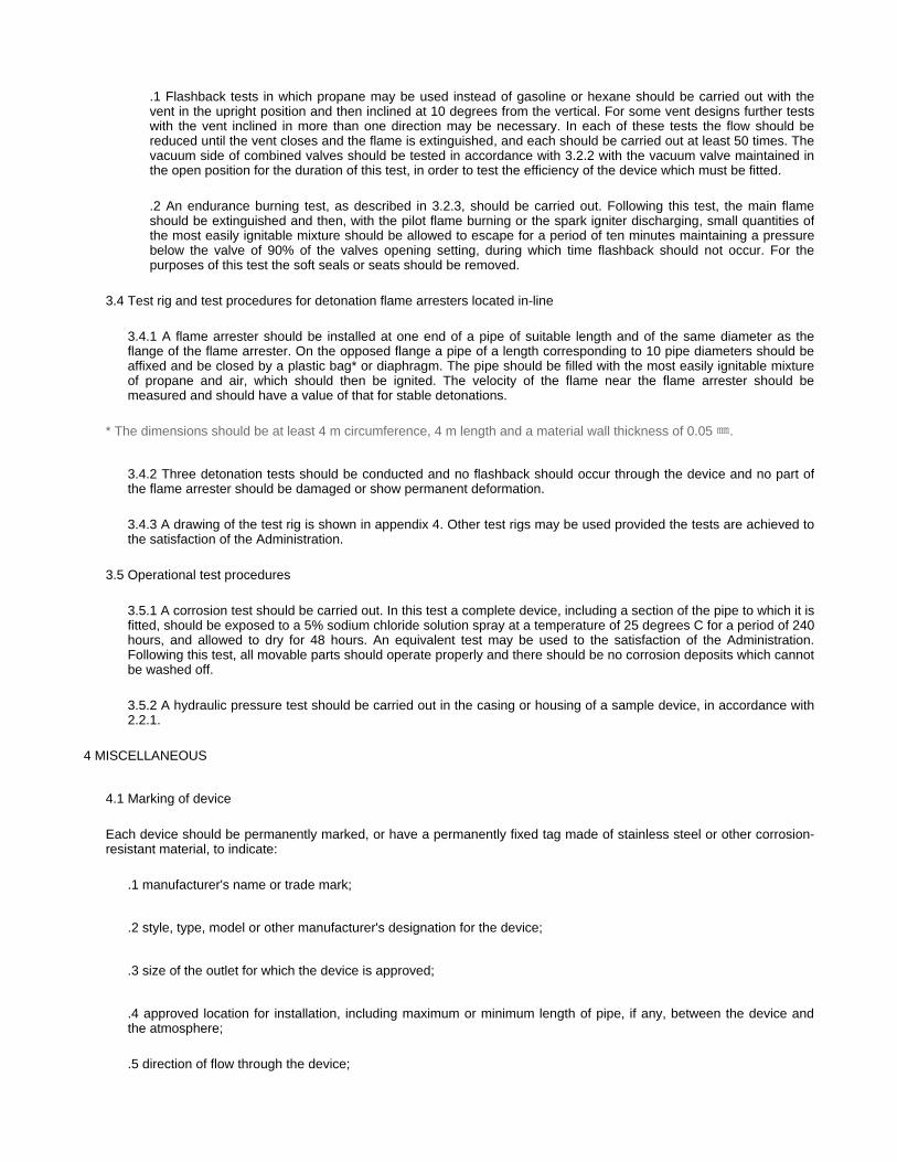
3.4 Test rig and test procedures for detonation flame arresters located in-line
3.5 Operational test procedures
4.1 Marking of device
Each device should be permanently marked, or have a permanently fixed tag made of stainless steel or other corrosion-resistant material, to indicate:
.1 Flashback tests in which propane may be used instead of gasoline or hexane should be carried out with the vent in the upright position and then inclined at 10 degrees from the vertical. For some vent designs further tests with the vent inclined in more than one direction may be necessary. In each of these tests the flow should be reduced until the vent closes and the flame is extinguished, and each should be carried out at least 50 times. The vacuum side of combined valves should be tested in accordance with 3.2.2 with the vacuum valve maintained in the open position for the duration of this test, in order to test the efficiency of the device which must be fitted.
.2 An endurance burning test, as described in 3.2.3, should be carried out. Following this test, the main flame should be extinguished and then, with the pilot flame burning or the spark igniter discharging, small quantities of the most easily ignitable mixture should be allowed to escape for a period of ten minutes maintaining a pressure below the valve of 90% of the valves opening setting, during which time flashback should not occur. For the purposes of this test the soft seals or seats should be removed.
3.4.1 A flame arrester should be installed at one end of a pipe of suitable length and of the same diameter as theflange of the flame arrester. On the opposed flange a pipe of a length corresponding to 10 pipe diameters should beaffixed and be closed by a plastic bag* or diaphragm. The pipe should be filled with the most easily ignitable mixtureof propane and air, which should then be ignited. The velocity of the flame near the flame arrester should bemeasured and should have a value of that for stable detonations.
* The dimensions should be at least 4 m circumference, 4 m length and a material wall thickness of 0.05 ㎜.
3.4.2 Three detonation tests should be conducted and no flashback should occur through the device and no part ofthe flame arrester should be damaged or show permanent deformation.
3.4.3 A drawing of the test rig is shown in appendix 4. Other test rigs may be used provided the tests are achieved tothe satisfaction of the Administration.
3.5.1 A corrosion test should be carried out. In this test a complete device, including a section of the pipe to which it isfitted, should be exposed to a 5% sodium chloride solution spray at a temperature of 25 degrees C for a period of 240hours, and allowed to dry for 48 hours. An equivalent test may be used to the satisfaction of the Administration.Following this test, all movable parts should operate properly and there should be no corrosion deposits which cannotbe washed off.
3.5.2 A hydraulic pressure test should be carried out in the casing or housing of a sample device, in accordance with2.2.1.
4 MISCELLANEOUS
.1 manufacturer's name or trade mark;
.2 style, type, model or other manufacturer's designation for the device;
.3 size of the outlet for which the device is approved;
.4 approved location for installation, including maximum or minimum length of pipe, if any, between the device andthe atmosphere;
.5 direction of flow through the device;

4.2 Laboratory report
4.3 Manufacturer's instruction manual
Appendix 1 Test rig for flash back rig.
.6 indication of the test laboratory and report number; and
.7 compliance with the requirements of MSC/Circ.677.
4.2.1 The laboratory report should include:
.1 detailed drawings of the device;
.2 types of tests conducted. Where in-line devices are tested, this information should include the maximum pressures and velocities observed in the test;
.3 specific advice on approved attachments;
.4 types of cargo for which the device is approved;
.5 drawings of the test rig;
.6 in the case of high velocity vent, the pressures at which the device opens and closes in the efflux velocity; and
.7 all the information marked on the device in 4.1.
4.3.1 The manufacturer should supply a copy of the instruction manual, which should be kept on board the tanker andwhich should include:
.1 installation instructions;
.2 operating instructions;
.3 maintenance requirements, including cleaning (see 2.3.3);
.4 copy of the laboratory report referred to in 4.2; and
.5 flow test data, including flow rates under both positive and negative pressures, operating sensitivity, flow resistance and velocity, should be provided.

Appendix 2 Schematic plan of the test plant for high velocity valves.
Appendix 3 Test rig for high velocity vents.
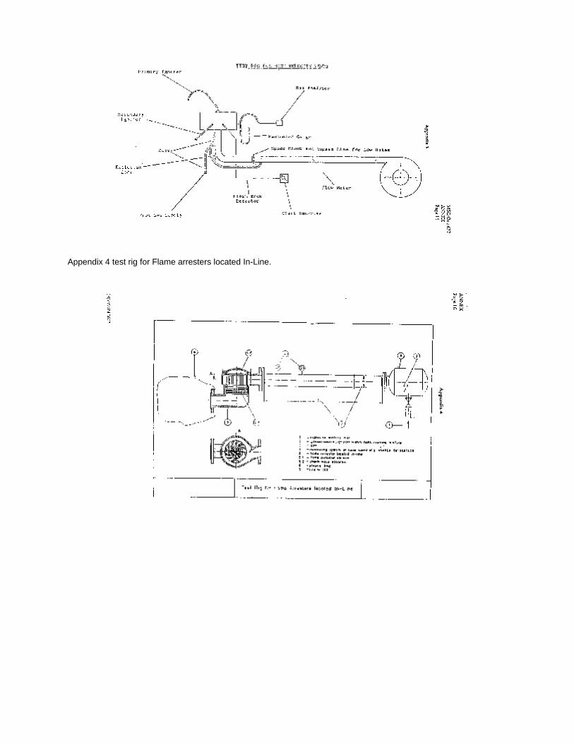
Appendix 4 test rig for Flame arresters located In-Line.
1 The Maritime Safety Committee, at its sixty-fourth session (5 to 9 December 1994), recognizing the urgent necessity of providing guidelines for alternative arrangements for halon fire-extinguishing systems, approved guidelines for the approval of equivalent water-based fire-extinguishing systems as referred to in SOLAS 74 for machinery spaces and cargo pump-rooms as MSC/Circ.668.
2 The Sub-Committee on Fire Protection, at its fortieth session (17 to 21 July 1995), reviewed the interim test method for equivalent water-based fire-extinguishing systems contained in MSC/Circ.668, and prepared amendments to the interim test method.
3 The Committee, at its sixty-sixth session (28 May to 6 June 1996), approved the amendments prepared by the FP Sub-Committee as contained in the annex.
4 Member Governments are invited to apply the guidelines contained in MSC/Circ.668 as amended by this circular.
1 In the third paragraph of "Scope", at the end of the first sentence after "ceiling mounted nozzles" insert the phrase "for class 1 and class 2 engine-rooms and multiple level nozzles for class 3 engine-rooms, that may be utilized in conjunction with a separate bilge area protection system"
2 Replace the test of paragraph 4.2.2.2 by the following test :
"4.2.2.2 Class 2 - Engine-room.
the tests should be performed in a room having a specified area greater than 100m2, specified height of from 5 to 7.5 and ventilation trough a 2 m x 2 door opening, up to a total valume for the room of 3,000m2, fires and engine mock-up should be according to tables 2 and 3 and figure 1.
4.2.2.3 Class 3 - Engine-room.
the test should be performed in a fire test hall with a minimum floor area of 300m2 , and a ceiling height in excess of 10m and without any restrictions air supply for the test fires. Fires and engine mock-up should be according to tables 2 and 3 and figure 1."
3 Replace the second sentence of paragraph 4.3 by the following. "For class 3 engine-rooms, the maximum vertical distance between levels of nozzles should be limited to 7.5m and the lowest level of nozzles should be at a minimum height of 5m above the floor."
4 Replace "30mm oil" in paragraph 4.4.1 by "50mm fuel"
5 Amend the Table 2 as follows
Title CIRCULAR / MSC/Circ.728
Amendment Status Amends MSC/Circ.668
REVISED TEST METHOD FOR EQUIVALENT WATER-BASED FIRE-EXTINGUISHING SYSTEMS FOR MACHINERY SPACES OF CATEGORY A AND CARGO PUMP-ROOMS
CONTAINED IN MSC/CIRC.668
ANNEX
AMENDMENTS TO THE TEST METHOD FOR EQUIVALENT WATER-BASED FIRE-EXTINGUISH SYSTEMS FOR MACHINERY SPACES OF CATEGORY A AND CARGO
PUMP-ROOMS COUNTAINED IN MSC/CIRC.668, ANNEX,APPEMDIX B
Test No. 9, tray size should be charged from "0.1m2"to "0.5m2"

Below the table replace the word "note"by"notes"
Denote existing note as "1" and add a new note "2" with the following test :
"2 tests 4, 7, 8 and 13 are not required for bilges with a separate fire protection system and are not applicable tobilges with a depth of more than 0.75m (see section 4.3)"

1 The International Convention for the Safety of Life at Sea, 1974, as amended, includes requirements for fire safety measures for tankers in regulations II-2/59 and 62. These regulations contain arrangements for venting, inerting, purging, gas-freeing and ventilation.
2 The Sub-Committee on Fire Protection has considered problems associated with the design of cargo tank venting and gas-freeing arrangements and the Maritime Safety Committee, at its fifty-third session (8 to 17 September 1986), approved MSC/Circ.450 on main factors that should be considered in the design of the arrangements referred to in paragraph 1 above. That circular was revised by the Committee, at its fifty-fifth session (11 to 20 April 1988), and issued as MSC/Circ.450/Rev.1.
3 The Committee, at its sixty-sixth session (28 May to 6 June 1996), taking into account the development of MSC/Circ.677 (Revised standards for the design, testing and locating of devices to prevent the passage of flame into cargo tanks in tankers), revised the aforementioned main factors as contained in the annex.
Maximum loading/discharge rate
The venting system should be designed to take into consideration the maximum permissible loading/discharge rate for each cargo tank and in the case of a combined venting system, for each group of tanks. These loading and discharge rates should also be used for the design of the inert gas system, regulation II-2/62.3.1.
Gas evolution
Regulation II-2/59.1.9.5 requires at least 25% to be added to the maximum loading rate to account for the increased volume due to gas evolution from the cargo. A higher gas evolution factor may be considered for highly volatile cargoes.
Pressure loss across devices
Data relating to pressure loss across devices to prevent the passage of flame, approved in accordance with MSC/Circ.677 and referred to in regulation II-2/59.1.5, is to be considered in the design of the venting system. Fouling of devices should be taken into account.
Pressure loss in the venting system
Pressure loss calculations of systems including pipes, valves, bends, fittings, etc., should be made to ensure that the pressure inside the cargo tanks does not exceed the pressure these tanks are designed to withstand taking into consideration .2 and .3 above. In the case where a combined venting system is used in association with loading of cargo tanks simultaneously, the combined effect of vapour pressure generated in the tanks and venting system should be considered.
Pressure at which the vents open
The initial opening pressure of the vent valves should be considered in selecting the appropriate valves for the venting system.
Prevention of hammering
In the case of high velocity vents, the possibility of inadvertent detrimental hammering leading to damage and/or failure should be considered, with a view to eliminating it.
Density of the gaseous mixture
Title CIRCULAR / MSC/Circ.731
REVISED FACTORS TO BE TAKEN INTO CONSIDERATION WHEN DESIGNING CARGO TANK VENTING AND GAS-FREEING ARRANGEMENTS
ANNEX

The maximum density of the gaseous mixtures likely to be encountered in the cargo tanks having regard to the types of cargo intended to be carried and their temperature is to be considered.
Design to prevent liquid overfill
Where overflow control systems are fitted, consideration is to be given to the dynamic conditions during loading.
Location of vent outlets
Horizontal and vertical distances of the vent outlets are to be in accordance with regulation II-2/59.
Types of venting systems
Due regard is to be given to cargo segregation when considering a venting system or inert gas system common to more than one tank. Where the inert gas main is designed for venting of cargo tanks, additional means for venting of these tanks are to be in accordance with regulation II-2/62.11.3.
Vent draining arrangements
The draining arrangements for venting systems are to be designed in accordance with regulation II-2/59.1.4.
Gas-freeing
In designing a gas-freeing system in conformity with paragraphs 2.2.2 and 2.2.3 of regulation II-2/59 in order to achieve the required exit velocities, the following should be considered:
Others
Repairs and renewal of the venting system should conform to the original design parameters. Factors in the above paragraphs are to be taken into consideration when modifications are carried out to the venting system.
The master is to be provided with a manual containing information relating to the maximum loading and unloading rates for each tank or group of tanks established during the design of the venting system, as per paragraph 1 of this circular.
Data referred to in paragraph 4.3 of MSC/Circ.677 should be taken into consideration when renewing devices referred to in the above circular.
.1 the flow characteristics of the fans to be used;
.2 the pressure losses created by the design of a particular tank's inlets and outlets;
.3 the pressure achievable in the fan driving medium (e.g. water or compressed air); and
.4 the densities of the cargo vapour air mixtures for the range of cargoes to be carried.

1 The Maritime Safety Committee, at its sixty-seventh session (2 to 6 December 1996), noted that the 1995 SOLAS Conference on Ro-Ro Ferry Safety, having noted a relevant recommendation made by the Panel of Experts, agreed that, for easy understanding by passengers on ro-ro passenger ships in particular, the words "assembly station" should be used to indicate "muster stations". As a consequence, the words "assembly station" were used in SOLAS regulations II-2/28-1 "Escape routes" and III/6 "Communications - Public address systems on passenger ships", as adopted by the Conference.
2 The Committee recalled that, at its sixty-sixth session (28 May to 6 June 1996), it adopted (resolution MSC.47(66)) a new SOLAS chapter III whereby the words "muster station" were retained.
3 Having noted the above discrepancy, the Committee agreed that the following footnote should be added in connection with any reference to "Assembly stations" in the amended SOLAS Convention:
4 The Committee further recommended that, for the purpose of assisting passengers on passenger ships to easily understand the issue, the words "assembly station" should be used on board as appropriate.
5 Member Governments are requested to take necessary action in line with the provisions of this circular.
Title CIRCULAR / MSC/Circ.777
INDICATION OF THE ASSEMBLY STATION IN PASSENGER SHIPS
"* "Assembly station" has the same meaning as "muster station"."

1 The Maritime Safety Committee, at its sixty-eighth session, approved the guidelines for the performance and testing criteria and surveys of medium-expansion foam concentrates for fire-extinguishing systems as contained in the annex.
2 Member Governments are recommended to ensure that tests for type approval and periodical control of the medium-expansion foam concentrates are performed in accordance with the attached guidelines.
1.1 Application
These guidelines apply to the foam concentrates for medium-expansion foam fire-extinguishing systems referred to in SOLAS regulation II-2/61.
1.2 Definitions
For the purpose of these Guidelines the following definitions apply:
2.1 The sampling method should ensure representative samples which should be stored in filled containers.
2.2 The sample size should be:
Title CIRCULAR / MSC/Circ.798
GUIDELINES FOR PERFORMANCE AND TESTING CRITERIA AND SURVEYS OF MEDIUM-EXPANSION CONCENTRATES FOR FIRE-EXTINGUISHING SYSTEMS
ANNEX
1 GENERAL
1.2.1 "Foam (fire fighting)": an aggregate of air filled bubbles formed from an aqueous solution of a suitable foamconcentrate;
1.2.2 "Foam solution": a solution of foam concentrate and water;
1.2.3 "Foam concentrate": the liquid which, when mixed with water in the appropriate concentration, gives a foamsolution;
1.2.4 "Expansion ratio": the ratio of the volume of foam to the volume of foam solution from which it was made;
1.2.5 "Spreading coefficient": a measurement of the ability of one liquid to spontaneously spread across another;
1.2.6 "25% (50%) drainage time": the time for 25% (50%) of the liquid content of a foam to drain out;
1.2.7 "Gentle application": application of foam to the surface of a liquid fuel via a backboard, tank wall or othersurface;
1.2.8 "Sediment": insoluble particles in the foam concentrate.
2 SAMPLING PROCEDURE
.1 30 litres for type tests (see Section 3)
.2 2 litres for periodical controls (see Section 4)

For foam concentrate type approval, the tests under paragraphs 3.1 to 3.10 should be performed. They should be carried out at laboratories acceptable to the Administration.
3.1 Freezing and thawing
3.2 Heat stability
An unopened 20 litre container (or other standard shipping container) as supplied by the manufacturer from a production batch should be maintained for 7 days at 60 degrees C, followed by one day at room temperature. Following this conditioning, the foam liquid after agitating/stirring will be subjected to the fire test as per 3.8, and comply with the requirements given in these guidelines.
3.3 Sedimentation
3 TESTS FOR TYPE APPROVAL OF FOAM CONCENTRATES
3.1.1 Before and after temperature conditioning in accordance with 3.1.2, the foam concentrate should show novisual sign of stratification, non-homogeneity or sedimentation.
3.1.2 Freeing and thawing test
.1 Apparatus:
.1 freezing chamber, capable of achieving temperatures required as stated in 2.1 below;
.2 polyethylene tube, approximately 10 mm diameter, 400 mm long and sealed and weighted at one end, with suitable spacers attached (Figure 1 of MSC/Circ.582 shows a typical form.)
.3 500 mL cylinder approximately 400 mm high and 65 mm diameter.
.2 Procedure:
.1 Set the temperature of the freezing chamber to a temperature which is 10 degrees C below the freezing point of the sample measured in accordance with BS 5117: Section 1.3 (excluding 5.2 in the standard).
To prevent the glass measuring cylinder from breaking, due to expansion of the foam concentrate on freezing, insert the tube into the measuring cylinder, sealed end downward, weighted if necessary to void floatation, the spacers ensuring it remains approximately on the central axis of the cylinder. Place the sample in the cylinder in the chest, cool and maintain at the required temperature for 24 hours. At the end of this period thaw the sample for not less than 24 hours and not more than 96 hours in an ambient temperature of 20-25 degrees C.
.2 Repeat .2.1 three times to give four cycles of freezing and thawing.
.3 Examine the sample for stratification and non-homogeneity.
.4 Condition the sample for 7 days at 60 degrees C followed by one day at room temperature.
3.3.1 Any sediment in the concentrate prepared in accordance with Section 2 should be dispersible through a 180micro m sieve, and the percentage volume of sediment should not be more than 0.25% when tested in accordancewith 3.3.2.
3.3.2 The test should be carried out as follows:
.1 Apparatus:

3.4 Kinematic viscosity
3.5 pH value
The pH value of the foam concentrate should be not less than 6.0 and not more than 10.0 at temperature of 20 +/- 2 degrees C.
3.6 Expansion ratio
.1 graduated centrifuge tubes;
.2 centrifuge operating at 6000 +/- 100 m/s**2;
.3 180 micro m sieve complying with ISO 3310-1;
.4 plastic wash bottle.
NOTE : A centrifuge and tubes complying with ISO 3734 are suitable.
.2 Procedure:
Centrifuge each sample for 10 minutes. Determine the volume of the sediment and determine the percentage of this volume with respect to the centrifuged sample volume. Wash the contents of the centrifuge tube onto the sieve and check that the sediment can or cannot be dispersed through the sieve by the jet from the plastic wash bottle.
NOTE : It is possible that the test method is not suitable for some non-Newtonian foam concentrates. In this case an alternative method, to the satisfaction of the Administration, should be used so that compliance with this requirement can be verified.
3.4.1 The test should be carried out according to ASTM D 445-86 or ISO 3104. Kinematic viscosity should not exceed 200 mm**2/s.
3.4.2 The method for determining viscosity of non-Newtonian foam concentrates should be to the satisfaction of the Administration.
3.6.1 The test should be carried out in accordance with paragraph 3.6.2 with sea water at about 20 degrees C.Simulated sea water with the characteristics stated under 3.6.3 may be used. The expansion ratio obtained with thefoam generators used on board should be consistent with the expansion ratio obtained with the foam generatorsduring the fire test.
3.6.2 Determination of the expansion ratio:
.1 Apparatus:
.1 plastic collecting vessel of volume V, approximately 200 L and accurately known to +/- 2 L;
(An example of suitable vessel is given in ISO 7203-2)
.2 medium-expansion foam-making equipment which when tested with water has a flow rate not less than (3.0 +/- 0.1) L/min at a nozzle pressure of (5.0 +/- 0.1) bar.
(An example of suitable apparatus is given in ISO 7203-2).
.2 Procedure
.1 Wet the vessel internally and weight it (W1). Set up the foam equipment and adjust the nozzle pressure of (5.0 +/- 0.1) bar. With the discharge facility closed, collect the foam in the vessel. As soon as the vessel is full,
3.7 Drainage time
3.8 Fire tests
Fire tests should be carried out in accordance with the following paragraphs 3.8.1 - 3.8.7 below.
stop collecting foam and strike the foam surface level with the rim. Weight the vessel (W2). During the filling operation, keep the discharge facility in the bottom of the vessel closed until the total weight of the foam is determined.
.2 Calculate the expansion E from the equation:
E = V/(W2 - W1)
where it is assumed that the density of the foam solution is 1.0 kg/L;
V is the vessel volume, in mL;
W1 is the mass of the empty vessel, in grammes; and
W2 is the mass of the full vessel, in grammes.
.3 Open the drainage facility and measure the 50% drainage time (see paragraph 3.7.1 below).
Determine the drainage either by having the vessel on a scale and recording the weight loss, or by collecting thedrained foam solution in a measuring cylinder.
3.6.3 Simulated sea water may be made up by dissolving:
25.0 g Sodium chloride (NaCl)
11.0 g Magnesium chloride (MgCl2 6H2O)
1.6 g Calcium chloride (CaCl2 2H2O)
4.0 g Sodium sulphate (Na2SO4)
3.7.1 The drainage time should be determined, after having determined the expansion ratio, in accordance withparagraph 3.6.2.3.
3.7.2 The test should be carried out with sea water at about 20 degrees C. simulated sea water with thecharacteristics stated in 3.6.3 may be used.
3.7.3 Drainage time obtained with the foam generators used on board should be consistent with the drainage timeobtained with the foam generators during the fire test.
NOTE : The fire tests of section 3.8 are more expensive and time consuming than the other tests of these guidelines. It is recommended that fire tests should be carried out at the end of the test programme, so as to avoid expense of unnecessary testing of foam concentrates which do not comply in other respects.
3.8.1 Environmental conditions
.1 Air temperature: (15 +/- 5) degrees C
.2 Maximum wind speed: 3 m/s in proximity of the fire tray.

Records
During the fire test, record the following:
.1 indoor or outdoor test
.2 air temperature
.3 fuel temperature
.4 water temperature
.5 foam solution temperature
.6 wind speed
.7 extinction time.
3.8.3 Foam solution
.1 Prepare a foam solution, following the recommendations from the supplier for concentration, maximum premixtime, compatibility with the test equipment, avoiding contamination by other types of foam, etc.
.2 The test should be carried out with sea water at about 20 degrees C. Simulated sea water with thecharacteristics stated in 3.6.3 may be used.
3.8.4 Apparatus
.1 Fire tray:
Circular fire tray of steel with dimensions as follows:
diameter at rim: (1,480 +/- 15) mm
depth (150 +/- 10) mm
normal thickness of steel wall 2.5 mm
NOTE : The tray has an area of approximately 1.73 m**2.
.2 Foam-making equipment:
In accordance with subparagraph 3.6.2.1.
3.8.5 Fuel
Use an aliphatic hydrocarbon mixture with physical properties according to the following specification:
.1 distillation range 84-105 degrees
.2 maximum difference between initial and boiling points 10 degrees C
.3 maximum aromatic content 1%
.4 density at 15 degrees (707.5 +/- 2.5) kg/m**3
3.9 Corrosiveness
The storage container shall be compatible with its foam concentrate, throughout the service life of the foam, such that the chemical and physical properties of the foam shall not deteriorate below the initial values accepted by the Administration.
3.10 Volumic mass
According to ASTMD 1298-85.
The attention of the Administration is drawn to the fact that particular installation conditions (excessive ambient temperature, incomplete filling of the tank etc.) may lead to an abnormal ageing of the concentrates. For the periodical control of foam concentrate the tests under paragraphs 4.1 to 4.5 should be performed. They should be carried out at laboratories acceptable to the Administration. The deviations in the values obtained by these tests, in respect of those obtained during the type approval tests, should be within ranges acceptable to the Administration. Tests under items 4.1, 4.3 and 4.4 should be carried out on samples maintained at 60 degrees C for 24 hours and subsequently cooled to the test temperature.
4.1 Sedimentation
According to paragraph 3.3 above.
4.2 pH value
According to paragraph 3.5 above.
4.3 Expansion ratio
According to paragraph 3.6 above.
4.4 Drainage time
.5 temperature about 20 degrees C.
NOTE : Typical fuels meeting this specification are n-hepthane and certain solvent fractions sometimes referred to as commercial hepthane.
The Administration may require additional fire tests using an additional test fuel.
3.8.6 Test procedure
3.8.6.1 Place the tray directly on the ground and ensure that it is level. Add approximately 30L of fresh water and (55 +/- 2) L of fuel, to give a nominal freeboard of 100 mm.
3.8.6.2 Not later than 5 minutes after adding of a fuel, ignite the fuel and allow it to burn free for a period of not less than 180 s after the full involvement. Set up the foam equipment at a height which is equal to the upper edge of the rim as it is shown at figure 1. 200 +/-5 s after full involvement of the surface into the fire, apply foam along the wall of the tray for a period of 120 +/- 2 s. Record the extinction time as the period from start of foam application to extinction.
3.8.7 Permissible limits
Extinction time % not more than 120 s.
4 PERIODICAL CONTROLS OF FOAM CONCENTRATES STORED ON BOARD

According to paragraph 3.7 above.
4.5 Volumic mass
According to paragraph 3.10 above.
The first periodical control of foam concentrates stored on board should be performed after a period of 3 years and, after that, every year. A record of the age of the foam concentrates and of subsequent controls should be kept on board.
Figure 1 - Fire test arrangement of medium expansion foam
5 INTERVALS OF PERIODICAL CONTROLS

1. The Maritime Safety Committee, at its sixty-seventh session (2 to 6 December 1996), approved Guidelines for the approval of equivalent fixed gas fire-extinguishing systems, as referred to in SOLAS 74, for machinery spaces and cargo pump-rooms, as MSC/Circ.776.
2. The Sub-Committee on Fire Protection, at its forty-second session (8 to 12 December 1997), recognized the need of technical improvement to the Guidelines contained in MSC/Circ. 776 to assist in their proper implementation and, to that effect, prepared amendments to the Guidelines.
3. The Committee, at its sixty-ninth session (11 to 20 May 1998), approved revised Guidelines for the approval of equivalent fixed gas fire-extinguishing systems, as referred to in SOLAS 74, for machinery spaces and cargo pump-rooms, as set out in the annex, to supersede the Guidelines attached to MSC/Circ.776.
4. Member Governments are invited to apply the annexed Guidelines when approving equivalent fixed gas fire-extinguishing systems for use in machinery spaces of category A and cargo pump-rooms.
1. Fixed gas fire-extinguishing systems for use in machinery spaces of category A and cargo pump-rooms equivalent to fire-extinguishing systems required by SOLAS regulations II-2-7 and II-2/63 should prove that they have the same reliability which has been identified as significant for the performance of fixed gas fire-extinguishing systems approved under the requirements of SOLAS regulation II-2/5. In addition, the system should be shown by test to have the capability of extinguishing a variety of fires that can occur in a ship's engine-room.
2. All requirements of SOLAS regulation II-2/5.1, 5.3.1, 5.3.2 to 5.3.3, except as modified by these guidelines, should apply.
3. The minimum extinguishing concentration should be determined by a cup burner test acceptable to the Administration. The design concentration should be at least 20% above the minimum extinguishing concentration. These concentration should be verified by full-scale testing described in the test method, as set out in the appendix.
4. For systems using halocarbon clean agents, 95% of the design concentration should be discharged in 10 s or less. For inert gas systems, the discharge time should not exceed 120 s for 85% of the design concentration.
5. The quantity of extinguishing agent for the protected space should be calculated at the minimum expected ambient temperature using the design concentration based on the net volume of the protected space, including the casing.
Title CIRCULAR / MSC/Circ.848
Amendment Status Supersedes MSC/Circ.776
IMO
REVISED GUIDELINES FOR THE APPROVAL OF EQUIVALENT FIXED GAS FIRE-EXTINGUISHING SYSTEMS, AS REFERRED TO IN SOLAS 74, FOR MACHINERY
SPACES AND CARGO PUMP-ROOMS
ANNEX
REVISED GUIDELINES FOR THE APPROVAL OF EQUIVALENT FIXED GAS FIRE-EXTINGUISHING SYSTEMS, AS REFERRED TO IN SOLAS 74, FOR MACHINERY
SPACES AND CARGO PUMP-ROOMS
General
Principal requirements
5.1 The net volume of a protected space is that part of the gross volume of the space which is accessible to the freeextinguishing agent gas.
6. No fire suppression agent should be used which is carcinogenic. mutagenic. or teratogenic at concentration expected during use. No agent should be used in concentrations greater than the cardiac sensitization NOAEL (No Observed Adverse Effect Level), without the use of controls as provided in SOLAS regulations II-2/5.2.5.1 and 5.2.5.2. In no case should an agent be used above its LOAEL (Lowest Observed Adverse Effects Level) nor ALC (Approximate Lethal Concentration) calculated on the net volume of the protected space at the maximum expected ambient temperature.
7. The system and its components should be suitably designed to withstand ambient temperature changes, vibration, humidity, shock, impact, clogging, and corrosion normally encountered in machinery spaces or cargo pump-rooms in ships.
8. The system and its components should be designed and installed in accordance with international standards acceptable to the Org anizat ion 1 and manufactured and tested to the satisfaction of the Administration. As a minimum, the design and installation standards should cover the following elements:
5.2 When calculating the net volume of a protected space, the net volume should include the volume of the bilge, thevolume of the casing and the volume of free air contained in air receivers that in the event of a fire is released into theprotected space.
5.3 The objects that occupy volume in the protected space should be subtracted from the gross volume of the space.They include, but are not necessarily limited to:
- auxiliary machinery;
- boilers;
- condensers;
- evaporators;
- main engines;
- reduction gears;
- tanks; and
- trunks.
5.4 Subsequent modifications to the protected space that alter the net volume of the space shall require the quantityof extinguishing agent to be adjusted to meet the requirements of this paragraph and paragraph 6.
¹ Until international standards are developed, national standards acceptable to the Administration should be used. Available national standards include, e.g., Standards of Australia, the United Kingdom and NFPA 2001.
.1 safety:
- toxicity;
- noise, nozzle discharge; and
- decomposition products;
.2 storage container design and arrangement:

- strength requirements;
- maximum/minimum fill density, operating temperature range;
- pressure and weight indication;
- Pressure relief; and
- agent identification and lethal requirements;
.3 agent supply, quantity, quality standards;
.4 pipe and fittings:
- strength, material, properties, fire resistance; and
- cleaning requirements;
.5 valves:
- testing requirements;
- corrosion resistance; and
- elastomer compatibility;
.6 Nozzles:
- height and area testing requirements; and
- corrosion and elevated temperature resistance;
.7 actuation and control systems:
- testing requirements; and
- backup power requirements;
.8 alarms and indicators:
- predischarge alarm, agent discharge alarms as time delays;
- abort switches;
- supervisory circuit requirements; and

9. The nozzle type, maximum nozzle spacing, maximum height and minimum nozzle pressure should be within limits tested to provide fire extinction per the proposed test method.
10. Provisions should be made to ensure that escape routes which are exposed to leakage from the protected space are not rendered hazardous during or after discharge of the agent. Control stations and other locations that require manning during a fire situation should have provisions to keep HF and HCL below 5 ppm at that location. The concentrations of other products should be kept below concentrations considered hazardous for the required duration of exposure.
11. Agent containers may be stored within a protected machinery space if the containers are distributed throughout the space and the provisions of SOLAS regulation II-2/5.3.3 are met. The arrangement of containers and electrical circuits and piping essential for the release of any system should be such that in single fault concept, at least five-sixths of the fire-extinguishing charge as required by paragraph 5 of this annex can still be discharged having regard to the requirement for uniform distribution of medium throughout the space. The arrangements in respect of systems for spaces requiring less than 6 containers should be to the satisfaction of the Administration.
12. A minimum agent hold time of 15 min should be provided.
13. The release of an extinguishing agent may produce significant over and under pressurization in the protected space. Measures to limit the induced pressures to acceptable limits should be provided.
14. For all ships, the fire-extinguishing system design manual should-address recommended procedures for the control of products of agent decomposition. The performance of fire-extinguishing arrangements on passenger ships should not present health hazards from decomposed extinguishing agents, e.g., on passenger ships, the decomposition products should not be discharged in the vicinity of muster (assembly) stations.
- warning signs and audible and visual alarms should be located outside each entry to the relevant space as appropriate;
.9 agent flow calculation:
- approval and testing of design calculation method; and
- fitting losses and/or equivalent length;
.10 enclosure integrity and leakage requirements:
- enclosure leakage;
- openings; and
- mechanical ventilation interlocks;
.11 design concentration requirements, total flooding quantity;
.12 discharge time; and
.13 inspection, maintenance, and testing requirements.
APPENDIX
TEST METHOD FOR FIRE TESTING OF FIXED GAS FIRE-EXTINGUISHING SYSTEMS
1. Scope
1.1 This test method is intended for evaluating the extinguishing effectiveness of fixed gas fire-extinguishing systems for the protection of machinery spaces of category A and cargo pump-rooms.
1.2 Fire-extinguishing systems presently covered in SOLAS regulation II-2/5, as amended, are excluded.
1.3 The text method covers the minimum requirements for fire-extinguishing.
1.4 This test method is applicable to gases, liquefied gases and mixtures of gases. The test method is not valid for extinguishing gases mixed with compounds in solid or liquid state at ambient conditions.
1.5 The test programme has two objectives:(1) establishing the extinguishing effectiveness of a given agent at its tested concentration, and (2) establishing that the particular agent distribution system puts the agent into the enclosure in such a way as to fully flood the volume to achieve an extinguishing concentration at all points.
The components to be tested should be supplied by the manufacturer together with design and installation criteria, operational instructions, drawings and technical data sufficient for the identification of the components.
3.1 Principle
This test procedure enables the determination of the effectiveness of different gaseous agent extinguishing systems against spray fires, pool fires and class A fires.
3.2 Apparatus
2. Sampling
3. Method of test
3.2.1 Test room
The tests should be performed in 100㎡room, with no horizontal dimension less than 8m, with a ceiling height of 5m.The test room should be provided with a closable access door measuring approximately 4㎡in area. In addition, closeable ventilation hatches measuring at least 6㎡in total area should be located in the ceiling.
3.2.2 Integrity of test enclosure
The test enclosure is to be nominally leak tight when doors and hatches are closed. The integrity of seals on doors,hatches, and other penetrations (e.g., instrumentation access ports) must be verified before each test.
3.2.3 Engine mock-up
.1 An engine mock-up of size (width × length × height) 1m × 3m × 3m should be constructed of sheet steel with a nominal thickness of 5mm. The mock-up should be fitted with two steel plate. At the top of the mock-up a 3㎡tray should be arranged. See figures 1,2 and 3.
.2 A floor plate system 4m × 6m × 0.75m high shall surround the mock-up. Provision shall be made for placement of the fuel trays, described in table 1, and located as described in table 2.
3.2.4 Instrumentation
Instrumentation for the continuous measurement and recording of test conditions should be employed. The followingmeasurements should be made:
.1 temperature at three vertical positions (e.g., 1, 2.5, and 4.5m)

3.3 Test fires and programme
.2 enclosure pressure
.3 gas sampling and analysis, at mid-room height, for oxygen, carbon dioxide, carbon monoxide, and relevant halogen acid products, e.g., hydrogen iodide, hydrofluoric acid, hydrochloric acid
.4 means of determining flame-out indicators
.5 fuel nozzle pressure in the case of spray fire
.6 fuel flow rate in the case of spray fires
.7 discharge nozzle pressure
3.2.5 Nozzles
3.2.5.1 For test purposes, nozzles should be located within 1 m of the ceiling.
3.2.5.2 If more than one nozzle is used they should be symmetrically located.
3.2.6 Enclosure temperature
The ambient temperature of the test enclosure at the start of the test should be noted and serve as the basis forcalculating the concentration that the agent would be expected to achieve at temperature and with that agent weightapplied in the test volume.
3.3.1 Fire types
The test programme, as described in table 3, should employ test fires as described in table 1.
Table 1 Parameters of Test Fires
Fire Type Fuel Fire Size remarks
A 76-100 mm ID Can Heptane 0.0012 to 0.002 Tell me
B 0.25㎡ Tray Heptane 0.35 C 2㎡Tray Diesel / Fuel Oil 3 D 4㎡Tray Diesel / Fuel Oil 6
E Low pressurespray
Heptane0.16±00.01kg/s 5.8
F Low pressure,low flow spray
Heptane0.03±0.0005kg/s 1.1
G High pressurespray Diesel / Fuel Oil 1.8
H Wood Crib Spruce or Fir 0.3 See NoteI 0.10㎡ tray Heptane 0.14
Notes to table 1:
1. Diesel/Fuel Oil means diesel or commercial fuel oil.

2. THE wood crib should be substantially the same as described in ISO/TC21/SC5/WG8 ISO Draft International Standard, Gaseous fire extinguishing systems, Part 1:General Requirements. The crib should consist of six, trade size 50mm ×50mm by 450mm long, kiln dried spruce or fir lumber having a moisture content between 9% and 13#. The members should be placed in 4 alternate layers at right angles to one another. Members should be evenly spaced forming a square structure. Achieve ignition of the crib by burning commercial grade heptane in a square steel tray 0.25㎡ in area. During the per-burn period the crib should be placed centrally above the top of the tray a distance of 300 to 600mm.
Table 2Spray fire test parameters
Fire type Low pressure(E) Low pressure(F) High pressure(G)
Spray nozzle Wide spray angle (120 to 125°)fuel cone type
Wide spray angle (80°)fuel cone type
Standard angle (at 6 Bar)fuel cone type
Nominal fuel pressure 8 Bar 8.5 Bar -150 BarFuel flow 0.16±0.01 kg/s 0.03±0.005 kg/s 0.050±0.002 kg/sFuel temperature 20±5° 20±5° 20±5°Nominal heat release 5.8±0.6 MW 1.1±0.1 MW 1.8±0.2 MW
3.3.2 Test programme
The fire test programme should employ test fires singly or in combination, as outlined in table 3.
Table 3Test Programme
Test No. Fire Combinations (See Table 1)1 A: Tell tales, 8 corners. See note.1.
2-aSee Note 2
B: 0.25 ㎡ heptane tray under engine mockupE: Horizontal LP spray directed at 15-25 min rod 0.5 m awayG: HP diesel/fuel oil spray on top of engine mock-up Total Fire Load : 7.95 MW
2-BSee Note 2
B: 0.25 ㎡ heptane tray under mockupI: 0.10 ㎡ heptane tray on deck plate located below solid steel obstruction plate Total Fire Load : 0.49 MW
3
C: 2㎡ diesel / fuel oil tray on deck plate located below solid steel obstruction plateH: Wood crib positioned as in Figure 1F: Low pressure, low flow horizontal spray - concealed - with impingement on inside of engine mock - up wall. Total Fire Load : 4.4 MW
4 D: 4㎡ Diesel tray under engine mock-up Total Fire Load : 6 MW
Note to table 3:
1 Tell-tale fire cans should be located as follows:
(a) in upper corners of enclosure 150 mm below ceiling and 50 mm from each wall;
(b) in corners on floors 50mm from walls.
2 Test 2-b is for use in evaluating extinguishing systems having discharge times greater than 10 seconds or less.
Test 2-b is for use in evaluating extinguishing systems having discharge times greater than 10 seconds.
3.3.2.1 All applicable tests of table 3 should be conducted for every new fire extinguishant gas, or mixture of gases.
3.3.2.2 Only Test 1 is required to evaluate new nozzles and related distribution system equipment (hardware) for systems employing fire extinguishants that have successfully completed the requirements of 3.3.2.1. Test 1
3.4 Extinguishing system
should be conducted to establish and verify the manufacturer's minimum nozzle design pressure.
3.4.1 System installation
The extinguishing system should be installed according to the manufacturer's design and installation instructions. Themaximum vertical distance should be limited to 5m
3.4.2 Agent
3.4.2.1 Design concentration
The agent design concentration is that concentration (in volume per cent) required by the system designer for the fire protection application.
3.4.2.2 Test concentration
The concentration of agent to be used in the fire extinguishing tests should be the design concentration specified by the extinguishing system manufacturer, except for Test 1 which should be conducted at 83% of the manufacturer's recommended design concentration but in no case at less than the cup burner extinguishing concentration.
3.4.2.3 Quantity of agent
The quantity of agent to be used should be determined as follows:
3.4.2.3.1 Halogenated agents
W = (V/S)·C/(100-C)
where :
W = agent mass, kg
V = volume of test enclosure, ㎥
S = agent vapour specific volume at temperature and pressure of the test enclosure, kg/㎥
C = gaseous agent concentration, volume per cent.
3.4.2.3.2 Inert gas agents
Q = V[294/(273 + T)]·(P/1.013)·In[100/(100 - C)]
where :
Q = volume of inert gas, measured at 294 K and 1.013 bar, discharged, ㎥
V = volume of test enclosure, ㎥
T = test enclosure temperature, Celsius
P = test enclosure pressure, bar
C = gaseous agent concentration, volume per cent.

3.5 Procedure
3.5.1 Fuel levels in trays
The trays used in the test should be filled with at least 30mm fuel on a water base. Freeboard should be 150 ± 10mm.
3.5.2 Fuel flow and pressure measurements
For spray fires, the fuel flow and pressure should be measured before and during each test.
3.5.3 Ventilation
3.5.3.1 Pre-burn period
During the pre-burn period the test enclosure should be well ventilated. The oxygen concentration, as measuredat mid-room height, shall not be less than 20 volume per cent at the time of system discharge.
3.5.3.2 End of pre-burn period
Doors, ceiling hatches, and other ventilation openings should be closed at the end of the pre-burn period.
3.5.4 Duration of test
3.5.4.1 Pre-burn time
Fires should be ignited such that the following burning times occur before the start of agent discharge:
.1 sprays - 5 to 15 s
.2 trays - 2 min
.3 crib - 6 min
3.5.4.2 Discharge time
.1 halogenated agents should be discharged at a rate sufficient to achieve delivery of 95% of the minimum design quantity in 10s or less
.2 inert gas agents should be discharged at a rate sufficient to achieve 85% of the minimum design quantity in 120s or less.
3.5.4.3 Soak time
After the end of agent discharge the test enclosure should be kept closed for 15min.
3.5.5 Measurements and observations
3.5.5.1 Before test
.1 temperature of test enclosure, fuel and engine mock-up
4.1 Class B fires must be extinguished within 30s of the end of agent discharge. At the end of the soak period there should be no reignition upon opening the enclosure.
4.2 The fuel spray should be shut off 15 s after extinguishment. At the end of the soak time, the fuel spray should be restarted for 15s prior to reopening the door and there should be no reignition.
4.3 At the end of the test fuel trays must contain sufficient fuel to cover the bottom of the tray.
4.4 Wood crib weight loss must be no more than 60%
.2 initial weights of agent containers
.3 verification of integrity agent distribution system and nozzles
.4 initial weight of wood crib.
3.5.5.2 During test
.1 start of the ignition procedure
.2 start of the test(ignition)
.3 time when ventilating
.4 time when the extinguishing system is activated.
.5 time from end of agent discharge.
.6 time when the fuel flow for the spray fire is shut off
.7 time when all fires are extinguished
.8 time of re-ignition, if any, during soak period
.9 time at end of soak period
.10 at the start of test initiate continuous monitoring as per 3.2.4.
3.5.6 Tolerances
Unless otherwise stated, the following tolerances should apply :
.1 length ±2% of value
.2 volume ±5% of value
.3 pressure ±3% of value
.4 temperature ±5% of value
.5 concentration ±5% of value.
These tolerances are in accordance with ISO standard(6121), 1994edition[4].
4. Classification criteria
The test report should include the following information:
5. Test report
.1 name and address of the test laboratory;
.2 date and identification number of the test report;
.3 name and address of client;
.4 purpose of the test;
.5 method of sampling system components;
.6 name and address of manufacturer or supplier of the product;
.7 name or other identification marks of the product;
.8 description of the tested product;
- drawings
- descriptions
- assembly instructions
- specification of included materials
- detailed drawing of test set-up;
.9 date of supply of the product;
.10 date of test;
.11 test method;
.12 drawing of each test configuration;
.13 identification of the test equipment and used instruments;
.14 conclusions;
.15 deviations from the test method, if any;
.16 test results including measurements and observations during and after the test; and
.17 date and signature.

Figure 1
Figure 2

Figure 3
I:\CIRC\MSC\1007.DOC
INTERNATIONAL MARITIME ORGANIZATION 4 ALBERT EMBANKMENT LONDON SE1 7SR Telephone: 020 7735 7611 Fax: 020 7587 3210 Telex: 23588 IMOLDN G
IMO
E
Ref. T4/4.01 MSC/Circ.1007 26 June 2001
GUIDELINES FOR THE APPROVAL OF FIXED AEROSOL FIRE-EXTINGUISHING SYSTEMS EQUIVALENT TO FIXED GAS FIRE-EXTINGUISHING SYSTEMS, AS
REFERRED TO IN SOLAS 74, FOR MACHINERY SPACES 1 The Maritime Safety Committee, at its seventy-fourth session (30 May to 8 June 2001), approved Guidelines for the approval of fixed aerosol fire-extinguishing systems equivalent to fixed gas fire-extinguishing systems, as referred to in SOLAS 74, for machinery spaces, as set out in the annex. 2 Member Governments are invited to apply the annexed Guidelines when approving fixed aerosol fire-extinguishing systems for use in machinery spaces of category A.
***

MSC/Circ.1007
I:\CIRC\MSC\1007.DOC
ANNEX
GUIDELINES FOR THE APPROVAL OF FIXED AEROSOL FIRE-EXTINGUISHING SYSTEMS EQUIVALENT TO FIXED GAS FIRE-EXTINGUISHING SYSTEMS, AS
REFERRED TO IN SOLAS 74, FOR MACHINERY SPACES General 1 Fixed aerosol fire-extinguishing systems for use in machinery spaces of category A equivalent to fire-extinguishing systems required by SOLAS regulation II-2/7* should prove that they have the same reliability which has been identified as significant for the performance of fixed gas fire-extinguishing systems approved under the requirements of SOLAS regulation II-2/5**. In addition, the system should be shown by testing according to the appendix to have the capability of extinguishing a variety of fires that can occur in machinery spaces. 2 Aerosol fire-extinguishing systems involve the release of a chemical agent to extinguish a fire by interruption of the process of the fire. There are two methods considered for applying the aerosol agent to the protected space: .1 condensed aerosols are created in pyrotechnical generators through the combustion of the
agent charge; and .2 dispersed aerosols that are not pyrotechnically generated and are stored in containers with
carrier agents (such as inert gases or halocarbon agents) with the aerosol released in the space through valves, pipes and nozzles.
Definitions 3 Aerosol is a non ozone depleting fire-extinguishing medium consisting of either condensed aerosol or dispersed aerosol. 4 Generator is a device for creating a fire-extinguishing medium by pyrotechnical means. 5 Design density (g/m³) is the mass of an aerosol forming composition per m³ of the enclosure volume required to extinguish a specific type of fire, including a safety factor. 6 Agent – medium for the purpose of these guidelines, these words are interchangeable. Principal requirements 7 All requirements of SOLAS regulations II-2/5.1***, 5.3.1, 5.3.2 to 5.3.3 except as modified by these guidelines, should apply, where applicable.
* Refer to regulation II-2/10.5 of SOLAS chapter II-2, as adopted by resolution MSC.99(73). ** Refer to regulation II-2/10.4 of SOLAS chapter II-2, as adopted by resolution MSC.99(73). *** Refer to regulation II-2/10.9.1.1.1 of SOLAS chapter II-2, as adopted by resolution MSC.99(73).
MSC/Circ.1007 ANNEX Page 2
I:\CIRC\MSC\1007.DOC
8 The minimum agent density should be determined and verified by the full-scale testing described in the test method, as set out in the appendix. 9 For aerosol systems, the discharge time should not exceed 120 s for 85% of the design density. Systems may need to discharge in a shorter time for other reasons than for fire-extinguishing performance. 10.1 The quantity of extinguishing agent for the protected space should be calculated at the minimum expected ambient temperature using the design density based on the net volume of the protected space, including the casing. 10.2 The net volume of a protected space is that part of the gross volume of the space, which is accessible to the fire-extinguishing agent. 10.3 When calculating the net volume of a protected space, the net volume should include the volume of the bilge, the volume of the casing and the volume of free air contained in air receivers that in the event of a fire may be released into the protected space. 10.4 The objects that occupy volume in the protected space should be subtracted from the gross volume of the space. They include, but are not necessarily limited to:
.1 auxiliary machinery;
.2 boilers;
.3 condensers;
.4 evaporators;
.5 main engines;
.6 reduction gears;
.7 tanks; and
.8 trunks.
10.5 Subsequent modifications to the protected space that alter the net volume of the space should require the quantity of extinguishing agent to be adjusted to meet the requirements of this paragraph and paragraphs 10.1, 10.2, 10.3, 10.4, 11.1, 11.2 and 11.3. 11.1 No fire suppression system should be used which is carcinogenic, mutagenic or teratogenic at concentrations expected during use. All systems should employ two separate controls for releasing the extinguishing medium into a protected space. Means should be provided for automatically giving audible warning of the release of fire-extinguishing medium into any space in which personnel normally work or to which they have access. The alarm should operate for a suitable period* before the medium is released. Unnecessary exposure to aerosol media, even at concentrations below an adverse effect level, should be avoided.
* Refer to the Interpretations of vague expressions and other vague wording in SOLAS chapter II-2 (MSC/Circ.847).
MSC/Circ.1007 ANNEX
Page 3
I:\CIRC\MSC\1007.DOC
11.2 Pyrotechnically generated aerosols: Pyrotechnically generated aerosol systems for spaces that are normally occupied should be permitted in concentrations where the aerosol particulate matter does not exceed the adverse effect level as determined by a scientifically accepted technique* and any gases produced by the pyrotechnic generator do not exceed the No Observed Adverse Effect Level (NOAEL) for the critical toxic effect as determined in a short term toxicity test. 11.3 Dispersed aerosols: Dispersed aerosol systems for spaces that are normally occupied should be permitted in concentrations where the aerosol particulate matter does not exceed the adverse effect level as determined by a scientifically accepted technique**. If the carrier gas is a halocarbon, it may be used up to its NOAEL. If a halocarbon carrier gas is to be used above its NOAEL, means should be provided to limit exposure to no longer than the time specified according to a scientifically accepted physiologically based pharmacokinetic** (PBPK) model or its equivalent which clearly establishes safe exposure limits both in terms of extinguishing media concentration and human exposure time. If the carrier is an inert gas, means should be provided to limit exposure to no longer than 5 min for inert gas systems designed to concentrations below 43% (corresponding to an oxygen concentration of 12%, sea level equivalent of oxygen) or to limit exposure to no longer than 3 min for inert gas systems designed to concentrations between 43% and 52% (corresponding to between 12% and 10% oxygen, sea level equivalent of oxygen). 11.4 In no case should a dispersed aerosol system be used with halocarbon carrier gas concentrations above the Lowest Observed Adverse Effect Level (LOAEL) nor the Approximate Lethal Concentration (ALC) nor should a dispersed aerosol system be used with an inert gas carrier at gas concentrations above 52% calculated on the net volume of the protected space at the maximum expected ambient temperature, without the use of controls as provided in SOLAS regulations II-2/5.2.5.1 and 5.2.5.2.*** 12 The system and its components should be suitably designed to withstand ambient temperature changes, vibration, humidity, shock, impact, clogging, electromagnetic compatibility and corrosion normally encountered in machinery spaces. Generators in condensed aerosol systems should be designed to prevent self-activation at a temperature below 250°C. 13 The system and its components should be designed, manufactured and installed in accordance with standards acceptable to the Organization. As a minimum, the design and installation standards should cover the following elements:
.1 safety:
.1 toxicity; .2 noise, generator/nozzle discharge;
* Reference is made to the United States’ EPA’s Regional Deposited Dose Ratio Program “Methods of Derivation of
Inhalation Reference Concentrations and Application of Inhalation Dosimetry” EPA/600/8-90/066F, October 1994. ** Refer to document FP 44/INF.2 (United States) – Physiologically based pharmacokinetic model to establish safe
exposure criteria for halocarbon fire extinguishing agents. *** Refer to regulation II-2/10.4.1.1.1 of SOLAS chapter II-2, as adopted by resolution MSC.99(73).

MSC/Circ.1007 ANNEX Page 4
I:\CIRC\MSC\1007.DOC
.3 decomposition products; and .4 obscuration;
.2 storage container design and arrangement:
.1 strength requirements; .2 maximum/minimum fill density, operating temperature range; .3 pressure and weight indication; .4 pressure relief; and .5 agent identification, production date, installation date and hazard classification;
.3 agent supply, quantity, quality standards, shelf life and service life of agent and igniter; .4 handling and disposal of generator after service life; .5 pipes and fittings:
.1 strength, material properties, fire resistance; and .2 cleaning requirements;
.6 valves:
.1 testing requirements; and .2 elastomer compatibility;
.7 generators/nozzles:
.1 height and area testing requirements; and .2 elevated temperature resistance;
.8 actuation and control systems:
.1 testing requirements; and .2 backup power requirements;
MSC/Circ.1007 ANNEX
Page 5
I:\CIRC\MSC\1007.DOC
.9 alarms and indicators:
.1 predischarge alarm, agent discharge alarms and time delays; .2 supervisory circuit requirements; .3 warning signs, audible and visual alarms; and .4 annunciation of faults;
.10 enclosure integrity and leakage requirements:
.1 enclosure leakage; .2 openings; and .3 mechanical ventilation interlocks;
.11 design density requirements, total flooding quantity; .12 agent flow calculation:
.1 verification and approval of design calculation method; .2 fitting losses and/or equivalent length; .3 discharge time;
.13 inspection, maintenance, service and testing requirements; and .14 handling and storage requirements for pyrotechnical components.
14 The generator/nozzle type, maximum generator/nozzle spacing, maximum generator/nozzle installation height and minimum generator/nozzle pressure should be within limits tested. 15 Installations should be limited to the maximum volume tested. 16 Agent containers may be stored within a protected machinery space if the containers are distributed throughout the space and the provisions of SOLAS regulation II-2/5.3.3, as applicable, are met. he arrangement of generators, containers, electrical circuits and piping essential for the release of any system should be such that in the event of damage to any one power release line through fire or explosion in the protected space (i.e. a single fault concept), at least the design density of the fire-extinguishing charge as required in paragraph 10 above can still be discharged having regard to the requirement for uniform distribution of medium throughout the space. 17 The release of an extinguishing agent may produce significant over and under pressurization in the protected space. Measures to limit the induced pressures to acceptable limits may have to be provided.

MSC/Circ.1007 ANNEX Page 6
I:\CIRC\MSC\1007.DOC
18 For all ships, the fire-extinguishing system design manual should address recommended procedures for the control of products of agent decomposition. The performance of fire-extinguishing arrangements on passenger ships should not present health hazards from decomposed extinguishing agents, (e.g., on passenger ships, the decomposition products should not be discharged in the vicinity of assembly stations). 19 Spare parts and operating and maintenance instructions for the system should be provided as recommended by the manufacturer.
MSC/Circ.1007 ANNEX
Page 7
I:\CIRC\MSC\1007.DOC
APPENDIX
TEST METHOD FOR FIRE TESTING OF FIXED AEROSOL FIRE-EXTINGUISHING SYSTEMS
1 Scope 1.1 This test method is intended for evaluating the extinguishing effectiveness of fixed aerosol fire-extinguishing systems for the protection of machinery spaces of category A. 1.2 The test method is applicable to aerosols and covers the minimum requirements for fire-extinguishing. 1.3 The test programme has two objectives: .1 establishing the extinguishing effectiveness of a given agent at its tested concentration; and .2 establishing that the particular agent distribution system puts the agent into the enclosure in
such a way as to fully flood the volume to achieve an extinguishing concentration at all points.
2 Sampling The components to be tested should be supplied by the manufacturer together with design and installation criteria, operational instructions, drawings and technical data sufficient for the identification of the components. 3 Method of test 3.1 Principle This test procedure is intended for the determination of the effectiveness of different aerosol agent extinguishing systems against spray fires, pool fires and class A fires. 3.2 Apparatus 3.2.1 Test room The tests should be performed in 100 m2 room, with no horizontal dimension less than 8 m, with a ceiling height of 5 m. The test room should be provided with a closable access door measuring approximately 4 m2 in area. In addition, closable ventilation hatches measuring at least 6 m2 in total area should be located in the ceiling. larger room may be employed if approvals are sought for larger volumes.
MSC/Circ.1007 ANNEX Page 8
I:\CIRC\MSC\1007.DOC
3.2.2 Integrity of test enclosure The test enclosure should be nominally leaktight when doors and hatches are closed. The integrity of seals on doors, hatches and other penetrations (e.g., instrumentation access ports) should be verified before each test. 3.2.3 Engine mock-up
.1 An engine mock-up of size (width x length x height) 1 m x 3 m x 3 m should be constructed of sheet steel with a nominal thickness of 5 mm. The mock-up should be fitted with two steel tubes diameter 0.3 m and 3 m length that simulate exhaust manifolds and a solid steel plate. At the top of the mock-up, a 3 m2 tray should be arranged (see figures 1, 2 and 3).
.2 A floor plate system 4 m x 6 m x 0.75 m high should surround the mock-up. Provision
should be made for placement of the fuel trays, as described in table 1, and located as described in table 2.
3.2.4 Instrumentation Instrumentation for the continuous measurement and recording of test conditions should be employed. The following measurements should be made:
.1 temperature at three vertical positions (e.g., 1 m, 2.5 m and 4.5 m);
.2 enclosure pressure;
.3 gas sampling and analysis, at mid-room height, for oxygen, carbon dioxide, carbon monoxide and other relevant products;
.4 means of determining flame-out indicators;
.5 fuel nozzle pressure in the case of spray fires;
.6 fuel flow rate in the case of spray fires;
.7 discharge nozzle pressure; and .8 means of determining generator discharge duration.
3.2.5 Generators/nozzles 3.2.5.1 For test purposes, generators/nozzles should be located within 1 m of the ceiling. 3.2.5.2 If more than one generator/nozzle is used, they should be symmetrically located.
MSC/Circ.1007 ANNEX
Page 9
I:\CIRC\MSC\1007.DOC
3.2.6 Enclosure temperature The ambient temperature of the test enclosure at the start of the test should be noted and serve as the basis for calculating the concentration that the agent would be expected to achieve at that temperature and with that agent weight applied in the test volume. 3.3 Test fires and programme 3.3.1 Fire types The test programme, as described in table 3, should employ test fires as described in table 1 below.
Table 1
Parameters of test fires
Fire Type Fuel Fire size, MW Remarks
A 76 - 100 mm ID can Heptane 0.0012 to 0.002 Tell tale
B 0.25 m2 tray Heptane 0.35
C 2 m2 tray Diesel /Fuel oil 3 (see Note 1)
D 4 m2 tray Diesel /Fuel oil 6 (see Note 1)
E Low pressure, low flow spray
Heptane 0.03 ± 0.005 kg/s
1.1
F Wood crib Spruce or fir 0.3 (See Note 2)
G 0.10 m2 tray Heptane 0.14
Notes to table 1: 1 Diesel/Fuel oil means light diesel or commercial fuel oil. 2 The wood crib should be substantially the same as described in ISO Standard 14520, Gaseous fire extinguishing
systems, Part 1: General Requirements (2000). The crib should consist of six, trade size 50 mm x 50 mm by 450 mm long, kiln dried spruce or fir lumber having a moisture content between 9% and 13%. The members should be placed in 4 alternate layers at right angles to one another. Members should be evenly spaced forming a square structure. Ignition of the crib should be achieved by burning commercial grade heptane in a square steel tray 0.25 m2 in area. During the pre-burn period the crib should be placed centrally above the top of the tray a distance of 300 to 600 mm.
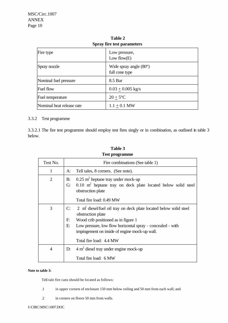
MSC/Circ.1007 ANNEX Page 10
I:\CIRC\MSC\1007.DOC
Table 2 Spray fire test parameters
Fire type Low pressure, Low flow(E)
Spray nozzle Wide spray angle (80°) full cone type
Nominal fuel pressure 8.5 Bar
Fuel flow 0.03 + 0.005 kg/s
Fuel temperature 20 + 5°C
Nominal heat release rate 1.1 + 0.1 MW
3.3.2 Test programme 3.3.2.1 The fire test programme should employ test fires singly or in combination, as outlined in table 3 below.
Table 3
Test programme
Test No. Fire combinations (See table 1)
1 A: Tell tales, 8 corners. (See note).
2
B: 0.25 m2 heptane tray under mock-up G: 0.10 m2 heptane tray on deck plate located below solid steel
obstruction plate
Total fire load: 0.49 MW
3 C: 2 m2 diesel/fuel oil tray on deck plate located below solid steel obstruction plate
F: Wood crib positioned as in figure 1 E: Low pressure, low flow horizontal spray - concealed - with impingement on inside of engine mock-up wall.
Total fire load: 4.4 MW
4 D: 4 m2 diesel tray under engine mock-up
Total fire load: 6 MW
Note to table 3:
Tell-tale fire cans should be located as follows:
.1 in upper corners of enclosure 150 mm below ceiling and 50 mm from each wall; and .2 in corners on floors 50 mm from walls.

MSC/Circ.1007 ANNEX Page 11
I:\CIRC\MSC\1007.DOC
3.3.2.2 All applicable tests of table 3 should be conducted for every new fire-extinguishing media. 3.3.2.3 Only test 1 is required to evaluate new nozzles and related distribution system equipment (hardware) for systems employing fire-extinguishing media that have successfully completed the requirements of paragraph 3.3.2.2 above. Test 1 should be conducted to establish and verify the manufacturer's minimum nozzle design pressure. 3.4 Extinguishing system 3.4.1 System installation The extinguishing system should be installed according to the manufacturer's design and installation instructions. The maximum vertical distance should be limited to 5 m. 3.4.2 Agent 3.4.2.1 Design density The agent design density is the net mass of extinguishant per unit volume (g/m3) required by the system designer for the fire protection application. 3.4.2.2 Test density The test density of agent to be used in the fire-extinguishing tests should be the design density specified by the manufacturer, except for test 1, which should be conducted at not more than 77% of the manufacturer’s recommended design density. 3.4.2.3 Quantity of aerosol agent
The quantity of aerosol agent to be used should be determined as follows: W = V x q (g), where: W = agent mass (g); V = volume of test enclosure (m3); q = fire-extinguishing aerosol density (g/m3). 3.5 Procedure 3.5.1 Fuel levels in trays The trays used in the test should be filled with at least 30 mm fuel on a water base. Freeboard should be 150 ± 10 mm.

MSC/Circ.1007 ANNEX Page 12
I:\CIRC\MSC\1007.DOC
3.5.2 Fuel flow and pressure measurements For spray fires, the fuel flow and pressure should be measured before and during each test. 3.5.3 Ventilation 3.5.3.1 Pre-burn period During the pre-burn period the test enclosure should be well ventilated. The oxygen concentration, as measured at mid-room height, should not be less than 20 volume per cent at the time of system discharge. 3.5.3.2 End of pre-burn period Doors, ceiling hatches and other ventilation openings should be closed at the end of the pre-burn period. 3.5.4 Duration of test 3.5.4.1 Pre-burn time Fires should be ignited such that the following burning times occur before the start of agent discharge:
.1 sprays - 5 to 15 s .2 trays - 2 min .3 crib - 6 min
3.5.4.2 Discharge time Aerosol agents should be discharged at a rate sufficient to achieve 85% of the minimum design density in 120 s or less. 3.5.4.3 Hold time After the end of agent discharge the test enclosure should be kept closed for 15 min. 3.5.5 Measurements and observations 3.5.5.1 Before test
.1 temperature of test enclosure, fuel and engine mock-up; .2 initial weights of agent containers; .3 verification of integrity agent distribution system and nozzles; and .4 initial weight of wood crib.

MSC/Circ.1007 ANNEX Page 13
I:\CIRC\MSC\1007.DOC
3.5.5.2 During test
.1 start of the ignition procedure; .2 start of the test (ignition); .3 time when ventilating openings are closed; .4 time when the extinguishing system is activated; .5 time from end of agent discharge; .6 time when the fuel flow for the spray fire is shut off; .7 time when all fires are extinguished; .8 time of re-ignition, if any, during hold time; .9 time at end of hold time; and .10 at the start of test initiate continuous monitoring as per 3.2.4.
3.5.6 Tolerances Unless otherwise stated, the following tolerances should apply:
.1 length ±2% of value;
.2 volume ±5% of value;
.3 pressure ±3% of value;
.4 temperature ±5% of value; and
.5 concentration ±5% of value. These tolerances are in accordance with ISO standard 6182/1, February 1994 edition 4. 4 Classification criteria 4.1 Class B fires should be extinguished within 30 s of the end of agent discharge. At the end of the hold period there should be no reignition upon opening the enclosure. 4.2 The fuel spray should be shut off 15 s after extinguishments. At the end of the hold time, the fuel spray should be restarted for 15 s prior to reopening the door and there should be no reignition.

MSC/Circ.1007 ANNEX Page 14
I:\CIRC\MSC\1007.DOC
4.3 The ends of the test fuel trays should contain sufficient fuel to cover the bottom of the tray. 4.4 Wood crib weight loss should be no more than 60%. 4.5 A reignition test should be conducted after the successful extinguishments of the tell-tale fires in test 1 (Fire A) within 30 s after completion of agent discharge. The test should involve the attempted ignition of two of the tell-tale fire containers. One container should be at the floor level and the other at the ceiling level at the diagonally opposite corner. At 10 min after extinguishment of the fires, a remotely operated electrical ignition source should be energized for at least 10 s at each container. The test should be repeated at one min intervals four more times, the last at 14 min after extinguishment. Sustained burning for 30 s or longer of any of these ignition attempts constitutes a reignition test failure. 5 Test report The test report should include the following information:
.1 name and address of the test laboratory; .2 date and identification number of the test report; .3 name and address of client; .4 purpose of the test; .5 method of sampling system components; .6 name and address of manufacturer or supplier of the product; .7 name or other identification marks of the product; .8 description of the tested product;
.1 drawings;
.2 descriptions; .3 assembly instructions; .4 specification of included materials; and .5 detailed drawing of test set-up;
.9 date of supply of the product; .10 date of test;

MSC/Circ.1007 ANNEX Page 15
I:\CIRC\MSC\1007.DOC
.11 test method; .12 drawing of each test configuration; .13 identification of the test equipment and used instruments; .14 conclusions; .15 deviations from the test method, if any; .16 test results including measurements and observations during and after the test; and
.17 date and signature.
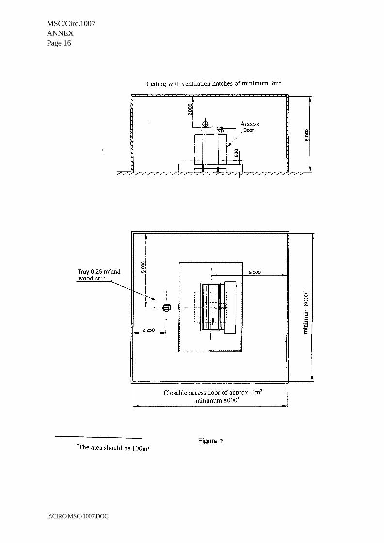
MSC/Circ.1007 ANNEX Page 16
I:\CIRC\MSC\1007.DOC

MSC/Circ.1007 ANNEX Page 17
I:\CIRC\MSC\1007.DOC
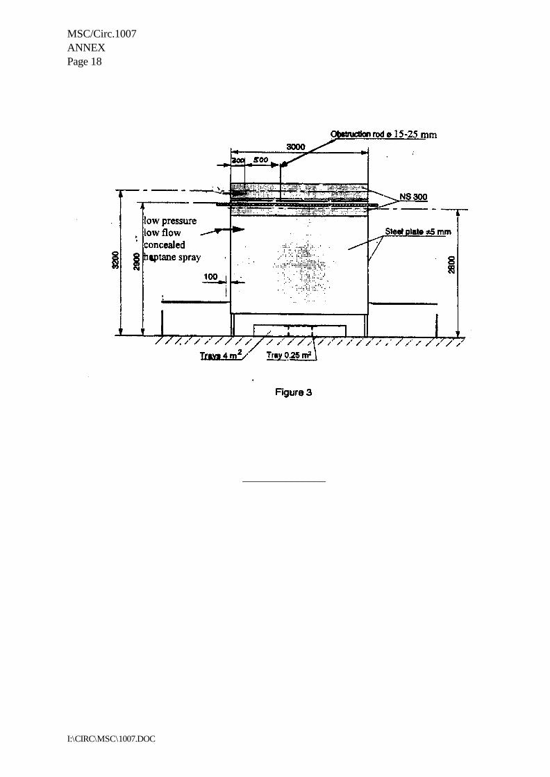
MSC/Circ.1007 ANNEX Page 18
I:\CIRC\MSC\1007.DOC
_______________
I:\CIRC\MSC\1009.doc
INTERNATIONAL MARITIME ORGANIZATION 4 ALBERT EMBANKMENT LONDON SE1 7SR Telephone: 020 7735 7611 Fax: 020 7587 3210 Telex: 23588 IMOLDN G
IMO
E
Ref. T4/4.01 MSC/Circ.1009 8 June 2001 AMENDMENTS TO THE REVISED STANDARDS FOR THE DESIGN, TESTING AND
LOCATING OF DEVICES TO PREVENT THE PASSAGE OF FLAME INTO CARGO TANKS IN TANKERS (MSC/CIRC.677)
1 The Maritime Safety Committee, at its seventy-fourth session (28 May to 8 June 2001), noting that ISO standard 15364 “Ships and marine technology - Pressure/vacuum valves for cargo tanks” was completed, approved amendments to paragraph 1.2.4 of the Revised standards for design, testing and locating of devices to prevent the passage of flame into cargo tanks in tankers (MSC/Circ.677), as follows:
“1.2.4 Devices should be tested and located in accordance with these standards. In addition to these standards, pressure/vacuum valves should comply with ISO standard 15364:2000 “Ships and marine technology - Pressure/vacuum valves for cargo tanks”.”
2 Member Governments are invited to apply the amendments to the Revised standards, in conjunction with regulation II-2/4* of the 1974 SOLAS Convention, as amended, for devices installed on or after 1 July 2002. 3 Member Governments are also invited to bring the annexed amendments to the Revised Standards to the attention of ship designers, ship owners and other parties involved in the design, construction and operation of tankers.
__________________
* Refers to the revised SOLAS chapter II-2 adopted by resolution MSC.99(73).
I:\CIRC\MSC\1165.doc
INTERNATIONAL MARITIME ORGANIZATION 4 ALBERT EMBANKMENT LONDON SE1 7SR Telephone: 020 7587 3152 Fax: 020 7587 3210
IMO
E
Ref. T4/4.01 MSC/Circ.1165 10 June 2005
REVISED GUIDELINES FOR THE APPROVAL OF EQUIVALENT WATER-BASED FIRE-EXTINGUISHING SYSTEMS FOR MACHINERY SPACES
AND CARGO PUMP-ROOMS 1 The Maritime Safety Committee, at its sixty-fourth session (5 to 9 December 1994), recognizing the urgent necessity of providing guidelines for alternative arrangements for halon fire-extinguishing systems, approved Guidelines for the approval of equivalent water-based fire-extinguishing systems as referred to in SOLAS 74 for machinery spaces and cargo pump-rooms (MSC/Circ.668). 2 The Committee, at its sixty-sixth session (28 May to 6 June 1996), having considered a proposal by the fortieth session of the Sub-Committee on Fire Protection to revise the interim test method for equivalent water-based fire-extinguishing systems, contained in MSC/Circ.668, approved a revised test method for equivalent water-based fire-extinguishing systems for category A machinery spaces and cargo pump-rooms contained in MSC/Circ.668 (MSC/Circ.728). 3 The Sub-Committee on Fire Protection, at its forty-ninth session (24 to 28 January 2005), reviewed the Guidelines for the approval of equivalent water-based fire-extinguishing systems as referred to in SOLAS 74 for machinery spaces and cargo pump-rooms (annex to MSC/Circ.668, as amended by MSC/Circ.728) and made amendments to the test method for equivalent water-based fire-extinguishing systems for machinery spaces of category A and cargo pump-rooms, taking into account the latest technological progress made in this area. 4 The Committee, at its eightieth session (11 to 20 May 2005), after having considered the above proposal by the forty-ninth session of the Sub-Committee on Fire Protection, approved Revised Guidelines for the approval of equivalent water-based fire-extinguishing systems for machinery spaces and cargo pump-rooms, as set out in the annex. 5 Member Governments are invited to apply the annexed Guidelines when approving equivalent water-based fire-extinguishing systems for machinery spaces and pump-rooms and bring them to the attention of ship designers, ship owners, equipment manufacturers, test laboratories and other parties concerned. 6 Test approvals already conducted in accordance with guidelines contained in MSC/Circ.668, as amended by MSC/Circ.728, should remain valid until 5 years after the date of this circular.
***

MSC/Circ.1165
I:\CIRC\MSC\1165.doc
ANNEX
REVISED GUIDELINES FOR THE APPROVAL OF EQUIVALENT WATER-BASED FIRE-EXTINGUISHING SYSTEMS
FOR MACHINERY SPACES AND CARGO PUMP-ROOMS
General 1 Water-based fire-extinguishing systems for use in machinery spaces of category A and cargo pump-rooms equivalent to fire-extinguishing systems required by SOLAS regulation II-2/10 and chapter 5 of the FSS Code should prove that they have the same reliability which has been identified as significant for the performance of fixed pressure water-spraying systems approved under the requirements of SOLAS regulation II-2/10 and chapter 5 of the FSS Code. In addition, the system should be shown by test to have the capability of extinguishing a variety of fires that can occur in a ship's engine-room. Definitions 2 Antifreeze system is a wet pipe system containing an antifreeze solution and connected to a water supply. The antifreeze solution is discharged, followed by water, immediately upon operation of nozzles. 3 Bilge area is the space between the solid engine-room floor plates and the bottom of the engine-room. 4 Deluge system is a system employing open nozzles attached to a piping system connected to a water supply through a valve that is opened by the operation of a detection system installed in the same areas as the nozzles or opened manually. When this valve opens, water flows into the piping system and discharges from all nozzles attached thereto. 5 Dry Pipe system is a system employing nozzles attached to a piping system containing air or nitrogen under pressure, the release of which (as from the opening of a nozzle) permits the water pressure to open a valve known as a dry pipe valve. The water then flows into the piping system and out of the opened nozzle. 6 Fire extinction is a reduction of the heat release from the fire and a total elimination of all flames and glowing parts by means of direct and sufficient application of extinguishing media. 7 Preaction system is a system employing automatic nozzles attached to a piping system containing air that mayor may not be under pressure, with a supplemental detection system installed in the same area as the nozzles. Actuation of the detection system opens a valve that permits water to flow into the piping system and to be discharged from any nozzles that may be open. 8 Water-based extinguishing medium is fresh water or seawater with or without additives mixed to enhance fire-extinguishing capability. 9 Wet pipe system is a system employing nozzles attached to a piping system containing water and connected to a water supply so that water discharges immediately from the nozzles upon system activation.

MSC/Circ.1165 ANNEX Page 2
I:\CIRC\MSC\1165.doc
Principal requirements for the system 10 The system should be capable of manual release. 11 The system should be capable of fire extinction, and tested to the satisfaction of the Administration in accordance with appendix B to these Guidelines. 12 The system should be available for immediate use and capable of continuously supplying water for at least 30 min in order to prevent re-ignition or fire spread within that period of time. Systems which operate at a reduced discharge rate after the initial extinguishing period should have a second full fire-extinguishing capability available within a 5-minute period of initial activation. 13 The system and its components should be suitably designed to withstand ambient temperature changes, vibration, humidity, shock, impact, clogging and corrosion normally encountered in machinery spaces or cargo pump-rooms in ships. Components within the protected spaces should be designed to withstand the elevated temperatures which could occur during a fire. 14 The system and its components should be designed and installed in accordance with international standards acceptable to the Organization1 and manufactured and tested to the satisfaction of the Administration in accordance with appropriate elements of appendices A and B to these guidelines. 15 The nozzle location, type of nozzle and nozzle characteristics should be within the limits tested to provide fire extinction as referred to in paragraph 10. 16 The electrical components of the pressure source for the system should have a minimum rating of IP 54. The system should be supplied by both main and emergency sources of power and should be provided with an automatic change-over switch. The emergency power supply should be provided from outside the protected machinery space. 17 The system should be provided with a redundant means of pumping. The capacity of the redundant means should be sufficient to compensate for the loss of any single supply pump. The system should be fitted with a permanent sea inlet and be capable of continuous operation using seawater. 18 The piping system should be sized in accordance with an hydraulic calculation technique.2 19 Systems capable of supplying water at the full discharge rate for 30 min may be grouped into separate sections within a protected space. The sectioning of the system within such spaces should be approved by the Administration in each case.
1 Pending the development of international standards acceptable to the Organization, national standards as prescribed
by the Administration should be applied. 2 Where the Hazen-Williams Method is used, the following values of the friction factor "C" for different pipe types
which may be considered should apply:
Pipe type C Black or galvanized mild steel 100 Copper and copper alloys 150 Stainless steel 150
MSC/Circ.1165 ANNEX
Page 3
I:\CIRC\MSC\1165.doc
20 In all cases the capacity and design of the system should be based on the complete protection of the space demanding the greatest volume of water. 21 The system operation controls should be available at easily accessible positions outside the spaces to be protected and should not be liable to be cut off by a fire in the protected spaces. 22 Pressure source components of the system should be located outside the protected spaces. 23 A means for testing the operation of the system for assuring the required pressure and flow should be provided. 24 Activation of any water distribution valve should give a visual and audible alarm in the protected space and at a continuously manned central control station. An alarm in the central control station should indicate the specific valve activated. 25 Operating instructions for the system should be displayed at each operating position. The operating instructions should be in the official language of the flag State. If the language is neither English nor French, a translation into one of these languages should be included. 26 Spare parts and operating and maintenance instructions for the system should be provided, as recommended by the manufacturer. 27 Additives should not be used for the protection of normally occupied spaces unless they have been approved for fire protection service by an independent authority. The approval should consider possible adverse health effects to exposed personnel, including inhalation toxicity.

MSC/Circ.1165 ANNEX Page 4
I:\CIRC\MSC\1165.doc
APPENDIX A
COMPONENT MANUFACTURING STANDARDS OF EQUIVALENT WATER-BASED FIRE-EXTINGUISHING SYSTEMS
TABLE OF CONTENTS
Introduction
1 Definitions
2 Product consistency
3 Water-mist nozzle requirements
3.1 Dimensions 3.2 Nominal release temperatures 3.3 Operating temperatures 3.4 Water flow and distribution 3.5 Function 3.6 Strength of body 3.7 Strength of release element 3.8 Leak resistance and hydrostatic strength 3.9 Heat exposure 3.10 Thermal shock 3.11 Corrosion 3.12 Integrity of nozzle coatings 3.13 Water hammer 3.14 Dynamic heating 3.15 Resistance to heat 3.16 Resistance to vibration 3.17 Impact test 3.18 Lateral discharge 3.19 30-day leakage resistance 3.20 Vacuum resistance 3.21 Water shield 3.22 Clogging
4 Methods of test
4.1 General 4.2 Visual examination 4.3 Body strength test 4.4 Leak resistance and hydrostatic strength tests 4.5 Functional test 4.6 Heat responsive element operating characteristics
4.6.1 Operating temperature test 4.6.2 Dynamic heating test

MSC/Circ.1165 ANNEX
Page 5
I:\CIRC\MSC\1165.doc
TABLE OF CONTENTS (continued) 4.7 Heat exposure test 4.8 Thermal shock test for glass bulb nozzles 4.9 Strength test for release elements 4.10 Water flow test 4.11 Corrosion tests
4.11.1 Stress corrosion tests for brass nozzle parts 4.11.2 Stress corrosion cracking of stainless steel nozzle parts 4.11.3 Sulphur dioxide corrosion test 4.11.4 Salt spray corrosion test 4.11.5 Moist air exposure test
4.12 Nozzle coating tests 4.13 Heat-resistance test 4.14 Water-hammer test 4.15 Vibration test 4.16 Impact test 4.17 Lateral discharge test 4.18 30-day leakage test 4.19 Vacuum test 4.20 Clogging test
5 Water-mist nozzle markings
5.1 General 5.2 Nozzle housing

MSC/Circ.1165 ANNEX Page 6
I:\CIRC\MSC\1165.doc
LIST OF FIGURES
Figure number Description _____________ __________________________________
1 RTI and C limits for standard orientation 2 Impact test apparatus 3 Clogging test apparatus
LIST OF TABLES
Table number Description ____________ __________________________________________________
1 Nominal release temperature 2 Plunge oven test conditions 3 Plunge oven test conditions for conductivity determinations 4 Test temperatures for coated and uncoated nozzles
5 Contaminant for contaminated water cycling test
Figures given in square brackets refer to ISO Standard 6182/1.
MSC/Circ.1165 ANNEX
Page 7
I:\CIRC\MSC\1165.doc
INTRODUCTION This document is intended to address minimum fire protection performance, construction, and marking requirements, excluding fire performance, for water-mist nozzles. Numbers in brackets following a section or sub-section heading refer to the appropriate section or paragraph in the Standard for Automatic sprinkler systems - Part 1: Requirements and methods of test for sprinklers, ISO 6182-1. The requirements for automatically operating nozzles which involve release mechanism need not be met by nozzles of manually operating systems. 1 DEFINITIONS 1.1 Conductivity factor is a measure of the conductance between the nozzle's heat responsive element and the fitting expressed in units of (m/s)0.5. 1.2 Rated working pressure is the maximum service pressure at which a hydraulic device is intended to operate. 1.3 Response time index (RTI) is a measure of nozzle sensitivity expressed as RTI = tu0.5, where t is the time constant of the heat responsive element in units of seconds, and u is the gas velocity expressed in metres per second. RTI can be used in combination with the conductivity factor (C) to predict the response of a nozzle in fire environments, defined in terms of gas temperature and velocity versus time. RTI has units of (m.s) 0.5. 1.4 Standard orientation. In the case of nozzles with symmetrical heat responsive elements supported by frame arms, standard orientation is with the air flow perpendicular to both the axis of the nozzle's inlet and the plane of the frame arms. In the case of non-symmetrical heat responsive elements, standard orientation is with the air flow perpendicular to both the inlet axis and the plane of the frame arms which produces the shortest response time. 1.5 Worst case orientation is the orientation which produces the longest response time with the axis of the nozzle inlet perpendicular to the air flow. 2 PRODUCT CONSISTENCY 2.1 It should be the responsibility of the manufacturer to implement a quality control programme to ensure that production continuously meets the requirements in the same manner as the originally tested samples. 2.2 The load on the heat responsive element in automatic nozzles should be set and secured by the manufacturer in such a manner so as to prevent field adjustment or replacement.

MSC/Circ.1165 ANNEX Page 8
I:\CIRC\MSC\1165.doc
3 WATER-MIST NOZZLE REQUIREMENTS 3.1 Dimensions Nozzles should be provided with a nominal 6 mm (1/4 in.) or larger nominal inlet thread or equivalent. The dimensions of all threaded connections should conform to International Standards where applied. National Standards may be used if International Standards are not applicable. 3.2 Nominal release temperatures (6.2) 3.2.1 The nominal release temperatures of automatic glass bulb nozzles should be as indicated in table 1. 3.2.2 The nominal release temperatures of fusible automatic element nozzles should be specified in advance by the manufacturer and verified in accordance with 3.3. Nominal release temperatures should be within the ranges specified in table 1.
Table 1 � Nominal release temperature
Values in degrees Celsius
GLASS BULB NOZZLES
FUSIBLE ELEMENT NOZZLES
Nominal release temp.
Liquid colour code
Nominal release temp.
Frame colour code *
57 68 79
93-100 121-141 163-182 204-343
orange
red yellow green blue
mauve black
57 to 77 80 to 107 121 to 149 163 to 191 204 to 246 260 to 343
uncoloured
white blue red
green orange
* Not required for decorative nozzles 3.3 Operating temperatures (see 4.6.1) [6.3] Automatic nozzles should open within a temperature range of X ± 0.035X + 0.62oC where X is the nominal release temperature.
MSC/Circ.1165 ANNEX
Page 9
I:\CIRC\MSC\1165.doc
3.4 Water flow and distribution 3.4.1 Flow constant (see 4.10) [6.4.1] 3.4.1.1 The flow constant K for nozzles is given in the following formula: K = Q/P0.5 where: P is the pressure in bars; and Q is the flow rate in litres per min. 3.4.1.2 The value of the flow constant K published in the Manufacturer�s Design and Installation Instructions should be verified using the test method of 4.10. The average flow constant K should be verified within ± 5% of the manufacturer�s value. 3.5 Function (see 4.5) [6.5] 3.5.1 When tested in accordance with 4.5, the nozzle should open and, within 5 s after the release of the heat responsive element, should operate satisfactorily by complying with the requirements of 4.10. Any lodgement of released parts should be cleared within 60 s of release for standard response heat responsive elements and within 10 s of release for fast and special response heat responsive elements or the nozzle should then comply with the requirement of 4.11. 3.5.2 The nozzle discharge components should not sustain significant damage as a result of the functional test specified in 4.5.6 and should have the same flow constant range and water droplet size and velocity within 5 per cent of values as previously determined per 3.4.1 and 3.4.3. 3.6 Strength of body (see 4.3) [6.6] The nozzle body should not show permanent elongation of more than 0.2% between the load-bearing points, after being subjected to twice the average service load, as determined using the method of 4.3.1. 3.7 Strength of release element [6.7] 3.7.1 Glass bulbs (see 4.9.1) The lower tolerance limit for bulb strength should be greater than two times the upper tolerance limit for the bulb design load based on calculations with a degree of confidence of 0.99 for 99 per cent of the samples as determined in 4.9.1. Calculations will be based on the Normal or Gaussian Distribution except where another distribution can be shown to be more applicable due to manufacturing or design factors. 3.7.2 Fusible elements (see 4.9.2) Fusible heat-responsive elements in the ordinary temperature range should be designed to:

MSC/Circ.1165 ANNEX Page 10
I:\CIRC\MSC\1165.doc
.1 sustain a load of 15 times its design load corresponding to the maximum service load measured in 4.3.1 for a period of 100 hours in accordance with 4.9.2.1; or
.2 demonstrate the ability to sustain the design load when tested in accordance
with 4.9.2.2. 3.8 Leak resistance and hydrostatic strength (see 4.4) [6.8] 3.8.1 A nozzle should not show any sign of leakage when tested by the method specified in 4.4.1. 3.8.2 A nozzle should not rupture, operate or release any parts when tested by the method specified in 4.4.2. 3.9 Heat exposure [6.9] 3.9.1 Glass bulb nozzles (see 4.7.1) There should be no damage to the glass bulb element when the nozzle is tested by the method specified in 4.7.1. 3.9.2 All uncoated nozzles (see 4.7.2) Nozzles should withstand exposure to increased ambient temperature without evidence of weakness or failure, when tested by the method specified in 4.7.2. 3.9.3 Coated nozzles (see 4.7.3) In addition to meeting the requirement of 4.7.2 in an uncoated version, coated nozzles should withstand exposure to ambient temperatures without evidence of weakness or failure of the coating, when tested by the method specified in 4.7.3. 3.10 Thermal shock (see 4.8) [6.10] Glass bulb nozzles should not be damaged when tested by the method specified in 4.8. Proper operation is not considered as damage. 3.11 Corrosion [6.11] 3.11.1 Stress corrosion (see 4.12.1 and 4.12.2) When tested in accordance with 4.12.1, all brass nozzles should show no fractures which could affect their ability to function as intended and satisfy other requirements. When tested in accordance with 4.12.2, stainless steel parts of water-mist nozzles should show no fractures or breakage which could affect their ability to function as intended and satisfy other requirements.
MSC/Circ.1165 ANNEX Page 11
I:\CIRC\MSC\1165.doc
3.11.2 Sulphur dioxide corrosion (see 4.12.3) Nozzles should be sufficiently resistant to sulphur dioxide saturated with water vapour when conditioned in accordance with 4.12.2. Following exposure, five nozzles should operate, when functionally tested at their minimum flowing pressure (see 3.5.1 and 3.5.2). The remaining five samples should meet the dynamic heating requirements of 3.14.2. 3.11.3 Salt spray corrosion (see 4.12.4) Coated and uncoated nozzles should be resistant to salt spray when conditioned in accordance with 4.12.4. Following exposure, the samples should meet the dynamic heating requirements of 3.14.2. 3.11.4 Moist air exposure (see 4.12.5) Nozzles should be sufficiently resistant to moist air exposure and should satisfy the requirements of 3.14.2 after being tested in accordance with 4.12.5. 3.12 Integrity of nozzle coatings [6.12] 3.12.1 Evaporation of wax and bitumen used for atmospheric protection of nozzles
(see 4.13.1) Waxes and bitumens used for coating nozzles should not contain volatile matter in sufficient quantities to cause shrinkage, hardening, cracking or flaking of the applied coating. The loss in mass should not exceed 5% of that of the original sample when tested by the method in 4.13.1. 3.12.2 Resistance to low temperatures (see 4.13.2) All coatings used for nozzles should not crack or flake when subjected to low temperatures by the method in 4.13.2. 3.12.3 Resistance to high temperature (see 3.9.3) Coated nozzles should meet the requirements of 3.9.3. 3.13 Water hammer (see 4.15) [6.13] Nozzles should not leak when subjected to pressure surges from 4 bar to four times the rated pressure for operating pressures up to 100 bars and two times the rated pressure for pressures greater than 100 bar. They should show no signs of mechanical damage when tested in accordance with 4.15 and should operate within the parameters of 3.5.1 at the minimum design pressure. 3.14 Dynamic heating (see 4.6.2) [6.14] 3.14.1 Automatic nozzles intended for installation in other than accommodation spaces and residential areas should comply with the requirements for RTI and C limits shown in figure 1. Automatic nozzles intended for installation in accommodation spaces or residential areas should comply with fast response requirements for RTI and C limits shown in figure 1. Maximum and minimum RTI values for all data points calculated using C for the fast and standard response nozzles

MSC/Circ.1165 ANNEX Page 12
I:\CIRC\MSC\1165.doc
should fall within the appropriate category shown in figure 1. Special response nozzles should have an average RTI value, calculated using C, between 50 and 80 with no value less than 40 or more than 100. When tested at an angular offset to the worst case orientation as described in section 4.6.2, the RTI should not exceed 600 (m.s)0.5 or 250% of the value of RTI in the standard orientation, whichever is less. The angular offset should be 15º for standard response, 20º for special response and 25º for fast response. 3.14.2 After exposure to the corrosion test described in sections 3.11.2, 3.11.3 and 3.11.4, nozzles should be tested in the standard orientation as described in section 4.6.2.1 to determine the post exposure RTI. All post exposure RTI values should not exceed the limits shown in figure 1 for the appropriate category. In addition, the average RTI value should not exceed 130% of the pre-exposure average value. All post exposure RTI values should be calculated as in section 4.6.2.3 using the pre-exposure conductivity factor (C). 3.15 Resistance to heat (see 4.14) [6.15] Open nozzles should be sufficiently resistant to high temperatures when tested in accordance with 4.14. After exposure, the nozzle should not show:
.1 visual breakage or deformation; .2 a change in flow constant K of more than 5 per cent; and .3 no changes in the discharge characteristics of the Water Distribution Test (see 3.4.2)
exceeding 5 per cent. 3.16 Resistance to vibration (see 4.16) [6.16] Nozzles should be able to withstand the effects of vibration without deterioration of their performance characteristics, when tested in accordance with 4.16. After the vibration test of 4.16, nozzles should show no visible deterioration and should meet the requirements of 3.5 and 3.8. 3.17 Impact test (see 4.17) [6.17] Nozzles should have adequate strength to withstand impacts associated with handling, transport and installation without deterioration of their performance or reliability. Resistance to impact should be determined in accordance with 4.1. 3.18 Lateral discharge (see 4.18) [6.19] Nozzles should not prevent the operation of adjacent automatic nozzles when tested in accordance with 4.21. 3.19 30 day leakage resistance (see 4.19) [6.20] Nozzles should not leak, sustain distortion or other mechanical damage when subjected to twice the rated pressure for 30 days. Following exposure, the nozzles should satisfy the test requirements of 4.22.
MSC/Circ.1165 ANNEX Page 13
I:\CIRC\MSC\1165.doc
3.20 Vacuum resistance (see 4.23) [6.21] Nozzles should not exhibit distortion, mechanical damage or leakage after being subjected to the test in 4.23. 3.21 Water shield [6.22 and 6.23] 3.21.1 General An automatic nozzle intended for use at intermediate levels or beneath open grating should be provided with a water shield which complies with 3.21.2 and 3.21.3. 3.21.2 Angle of protection (see 4.21.1) Water shields should provide an "angle of protection" of 45º or less for the heat responsive element against direct impingement of run-off water from the shield caused by discharge from nozzles at higher elevations. Compliance with this requirement should be determined in accordance with 4.21.1. 3.21.3 Rotation (see 4.21.2) Rotation of the water shield should not alter the nozzle service load when evaluated in accordance with 4.21.2. 3.22 Clogging (see 4.21) [6.28.3] A water-mist nozzle should show no evidence of clogging during 30 minutes of continuous flow at rated working pressure using water, which has been contaminated in accordance with 4.21.3. Following the 30 minutes of flow, the water flow at rated pressure of the nozzle and strainer or filter should be within ± 10 per cent of the value obtained prior to conducting the clogging test. 4 METHODS OF TEST [7] 4.1 General
The following tests should be conducted for each type of nozzle. Before testing, precise drawings of parts and the assembly should be submitted together with the appropriate specifications (using SI units). Tests should be carried out at an ambient temperature of (20,±5)ºC, unless other temperatures are indicated. 4.2 Visual examination [7.2]
Before testing, nozzles should be examined visually with respect to the following points:
.1 marking;
.2 conformity of the nozzles with the manufacturer's drawings and specification; and
.3 obvious defects.
MSC/Circ.1165 ANNEX Page 14
I:\CIRC\MSC\1165.doc
4.3 Body strength test [7.3] 4.3.1 The design load should be measured on ten automatic nozzles by securely installing each nozzle, at room temperature, in a tensile/compression test machine and applying a force equivalent to the application of the rated working pressure. 4.3.2 An indicator capable of reading deflection to an accuracy of 0.01 mm should be used to measure any change in length of the nozzle between its load bearing points. Movement of the nozzle shank thread in the threaded bushing of the test machine should be avoided or taken into account. 4.3.3 The hydraulic pressure and load is then released and the heat responsive element is then removed by a suitable method. When the nozzle is at room temperature, a second measurement is to be made using the indicator. 4.3.4 An increasing mechanical load to the nozzle is then applied at a rate not exceeding 500 N/minute, until the indicator reading at the load bearing point initially measured returns to the initial value achieved under hydrostatic load. The mechanical load necessary to achieve this should be recorded as the service load. Calculate the average service load. 4.3.5 The applied load is then progressively increased at a rate not exceeding 500 N/minute on each of the five specimens until twice the average service load has been applied. Maintain this load for 15 ± 5 s. 4.3.6 The load is then removed and any permanent elongation as defined in 3.6 is recorded. 4.4 Leak resistance and hydrostatic strength tests (see 3.8) [7.4] 4.4.1 Twenty nozzles should be subjected to a water pressure of twice their rated working pressure, but not less than 34.5 bar. The pressure is increased from 0 bar to the test pressure, maintained at twice rated working pressure for a period of 3 min and then decreased to 0 bar. After the pressure has returned to 0 bar, it is increased to the minimum operating pressure specified by the manufacturer in not more than 5 s. This pressure is to be maintained for 15 s and then increased to rated working pressure and maintained for 15 s. 4.4.2 Following the test of 4.4.1, the twenty nozzles should be subjected to an internal hydrostatic pressure of four times the rated working pressure. The pressure is increased from 0 bar to four times the rated working pressure and held there for a period of 1 minute. The nozzle under test should not rupture, operate or release any of its operating parts during the pressure increase nor while being maintained at four times the rated working pressure for 1 minute. 4.5 Functional test (see 3.5) [7.5] 4.5.1 Nozzles having nominal release temperatures less than 78°C, should be heated to activation in an oven. While being heated, they should be subjected to each of the water pressures specified in 4.5.3 applied to their inlet. The temperature of the oven should be increased to 400 ± 20°C in 3 min measured in close proximity to the nozzle. Nozzles having nominal release temperatures exceeding 78°C should be heated using a suitable heat source. Heating should continue until the nozzle has activated.

MSC/Circ.1165 ANNEX Page 15
I:\CIRC\MSC\1165.doc
4.5.2 Eight nozzles should be tested in each normal mounting position and at pressures equivalent to the minimum operating pressure, the rated working pressure and at the average operating pressure. The flowing pressure should be at least 75% of the initial operating pressure. 4.5.3 If lodgement occurs in the release mechanism at any operating pressure and mounting position, 24 more nozzles should be tested in that mounting position and at that pressure. The total number of nozzles for which lodgement occurs should not exceed 1 in the 32 tested at that pressure and mounting position. 4.5.4 Lodgement is considered to have occurred when one or more of the released parts lodge in the discharge assembly in such a way as to cause the water distribution to be altered after the period of time specified in 3.5.1. 4.5.5 In order to check the strength of the deflector/orifice assembly, three nozzles should be submitted to the functional test in each normal mounting position at 125 per cent of the rated working pressure. The water should be allowed to flow at 125 per cent of the rated working pressure for a period of 15 min. 4.6 Heat responsive element operating characteristics
4.6.1 Operating temperature test (see 3.3) [7.6]
4.6.1.1 Ten nozzles should be heated from room temperature to 20 to 22°C below their nominal release temperature. The rate of increase of temperature should not exceed 20°C/min and the temperature should be maintained for 10 min. The temperature should then be increased at a rate between 0.4°C/min to 0.7°C/min until the nozzle operates. 4.6.1.2 The nominal operating temperature should be ascertained with equipment having an accuracy of ±0.35% of the nominal temperature rating or ±0.25°C, whichever is greater. 4.6.1.3 The test should be conducted in a water bath for nozzles or separate glass bulbs having nominal release temperatures less than or equal to 80°C. A suitable oil should be used for higher-rated release elements. The liquid bath should be constructed in such a way that the temperature deviation within the test zone does not exceed 0.5%, or 0.5°C, whichever is greater. 4.6.2 Dynamic heating test (see 3.4) 4.6.2.1 Plunge test 4.6.2.1.1 Tests should be conducted to determine the standard and worst case orientations as defined in 1.4 and 1.5. Ten additional plunge tests should be performed at both of the identified orientations. The worst case orientation should be as defined in 3.14.1. The RTI is calculated as described in 4.6.2.3 and 4.6.2.4 for each orientation, respectively. The plunge tests are to be conducted using a brass nozzle mount designed such that the mount or water temperature rise does not exceed 2°C for the duration of an individual plunge test up to a response time of 55 s. (The temperature should be measured by a thermocouple heatsinked and embedded in the mount not more than 8 mm radially outward from the root diameter of the internal thread or by a thermocouple located in the water at the centre of the nozzle inlet.) If the response time is greater than 55 s, then the mount or water temperature in degrees Celsius should not increase more than 0.036 times the response time in seconds for the duration of an individual plunge test.
MSC/Circ.1165 ANNEX Page 16
I:\CIRC\MSC\1165.doc
4.6.2.1.2 The nozzle under test should have 1 to 1.5 wraps of PTFE sealant tape applied to the nozzle threads. It should be screwed into a mount to a torque of 15 ±3 Nm. Each nozzle is to be mounted on a tunnel test section cover and maintained in a conditioning chamber to allow the nozzle and cover to reach ambient temperature for a period of not less than 30 min. 4.6.2.1.3 At least 25 ml of water, conditioned to ambient temperature, should be introduced into the nozzle inlet prior to testing. A timer accurate to ±0.01 s with suitable measuring devices to sense the time between when the nozzle is plunged into the tunnel and the time it operates should be utilized to obtain the response time. 4.6.2.1.4 A tunnel should be utilized with air flow and temperature conditions1 at the test section (nozzle location) selected from the appropriate range of conditions shown in table 2. To minimize radiation exchange between the sensing element and the boundaries confining the flow, the test section of the apparatus should be designed to limit radiation effects to within ± 3% of calculated RTI values2. 4.6.2.1.5 The range of permissible tunnel operating conditions is shown in table 2. The selected operating condition should be maintained for the duration of the test with the tolerances as specified by footnotes 4 and 5 in table 2. 4.6.2.2 Determination of conductivity factor (C) [7.6.2.2] The conductivity factor (C) should be determined using the prolonged plunge test (see 4.6.2.2.1) or the prolonged exposure ramp test (see 4.6.2.2.2). 4.6.2.2.1 Prolonged plunge test [7.6.2.2.1]
.1 the prolonged plunge test is an iterative process to determine C and may require up to twenty nozzle samples. A new nozzle sample must be used for each test in this section even if the sample does not operate during the prolonged plunge test;
.2 the nozzle under test should have 1 to 1.5 wraps of PTFE sealant tape applied to the
nozzle threads. It should be screwed into a mount to a torque of 15 + 3 Nm. Each nozzle is to be mounted on a tunnel test section cover and maintained in a conditioning chamber to allow the nozzle and cover to reach ambient temperature for a period of not less than 30 min. At least 25 ml of water, conditioned to ambient temperature, should be introduced into the nozzle inlet prior to testing;
.3 a timer accurate to ± 0.01 s with suitable measuring devices to sense the time
between when the nozzle is plunged into the tunnel and the time it operates should be utilized to obtain the response time;
.4 the mount temperature should be maintained at 20 ± 0.5°C for the duration of each
test. The air velocity in the tunnel test section at the nozzle location should be maintained with ± 2% of the selected velocity. Air temperature should be selected and maintained during the test as specified in table 3;
1 Tunnel conditions should be selected to limit maximum anticipated equipment error to 3%. 2 A suggested method for determining radiation effects is by conducting comparative plunge tests on a blackened
(high emissivity) metallic test specimen and a polished (low emissivity) metallic test specimen.

MSC/Circ.1165 ANNEX Page 17
I:\CIRC\MSC\1165.doc
.5 the range of permissible tunnel operating conditions is shown in table 3. The
selected operating condition should be maintained for the duration of the test with the tolerances as specified in table 3; and
.6 to determine C, the nozzle is immersed in the test stream at various air velocities for a
maximum of 15 min.1 Velocities are chosen such that actuation is bracketed between two successive test velocities. That is, two velocities must be established such that at the lower velocity (uj) actuation does not occur in the 15 min test interval. At the next higher velocity (uh), actuation must occur within the 15 min time limit. If the nozzle does not operate at the highest velocity, select an air temperature from table 3 for the next higher temperature rating.
Table 2 � Plunge oven test conditions
Air temperature ranges* Velocity ranges**
Normal
Temperature, ºC
Standard Response,
ºC
Special
Response, ºC
Fast
Response, m/s
Standard Response,
m/s
Special
Response, m/s
Fast
Response Nozzle, m/s
57 to 77
191 to 203
129 to 141
129 to 141
2.4 to 2.6
2.4 to 2.6
1.65 to 1.85
79 to 107
282 to 300
191 to 203
191 to 203
2.4 to 2.6
2.4 to 2.6
1.65 to 1.85
121 to 149
382 to 432
282 to 300
282 to 300
2.4 to 2.6
2.4 to 2.6
1.65 to 1.85
163 to 191
382 to 432
382 to 432
382 to 432
3.4 to 3.6
2.4 to 2.6
1.65 to 1.85
* The selected air temperature should be known and maintained constant within the test section throughout the test to
an accuracy of ±1ºC for the air temperature range of 129 to 141ºC within the test section and within ±2ºC for all other air temperatures.
** The selected air velocity should be known and maintained constant throughout the test to an accuracy of ±0.03 m/s
for velocities of 1.65 to 1.85 and 2.4 to 2.6 m/s and ±0.04 m/s for velocities of 3.4 to 3.6 m/s.
Table 3 � Plunge oven test conditions for conductivity determination
Nominal nozzle temperature,
ºC
Oven temperature, ºC
Maximum variation of air temperature during test,
ºC
57
85 to 91
± 1.0 58 to 77 124 to 130 ± 1.5
78 to 107 193 to 201 ± 3.0 121 to 149 287 to 295 ± 4.5 163 to 191 402 to 412 ± 6.0
1 If the value of C is determined to be less than 0.5 (m.s)0.5 a C of 0.25 (m.s)0.5 should be assumed for calculating
RTI value.

MSC/Circ.1165 ANNEX Page 18
I:\CIRC\MSC\1165.doc
Test velocity selection should ensure that:
(UH/UL)0.5 ≤ 1.1
The test value of C is the average of the values calculated at the two velocities using the
following equation: C = (∆ Tg/ ∆Tea - 1)u0.5
where:
∆ Tg Actual gas (air) temperature minus the mount temperature (Tm) in ºC.
∆ Tea Mean liquid bath operating temperature minus the mount temperature (Tm) in ºC.
u Actual air velocity in the test section in m/s.
The nozzle C value is determined by repeating the bracketing procedure three times and calculating the numerical average of the three C values. This nozzle C value is used to calculate all standard orientation RTI values for determining compliance with 3.14.1. 4.6.2.2.2 Prolonged exposure ramp test [7.6.2.2.2] .1 the prolonged exposure ramp test for the determination of the parameter C should be
carried out in the test section of a wind tunnel and with the requirements for the temperature in the nozzle mount as described for the dynamic heating test. A preconditioning of the nozzle is not necessary;
.2 ten samples should be tested of each nozzle type, all nozzles positioned in standard
orientation. The nozzle should be plunged into an air stream of a constant velocity of 1 m/s ± 10% and an air temperature at the nominal temperature of the nozzle at the beginning of the test; and
.3 the air temperature should then be increased at a rate of 1 ± 0.25ºC/min until the
nozzle operates. The air temperature, velocity and mount temperature should be controlled from the initiation of the rate of rise and should be measured and recorded at nozzle operation. The C value is determined using the same equation as in 4.6.2.2.1 as the average of the ten test values.
4.6.2.3 RTI value calculation [7.6.2.3] The equation used to determine the RTI value is as follows:
]/))/(1( - [1)/1()(5.0
5.05.0
gea
r
TuCTInuCutRTI
∆+∆+−
=
where: tr Response time of nozzles in seconds u Actual air velocity in the test section of the tunnel in m/s from table 2

MSC/Circ.1165 ANNEX Page 19
I:\CIRC\MSC\1165.doc
∆ Tea Mean liquid bath operating temperature of the nozzle minus the ambient
temperature in ºC ∆Tg Actual air temperature in the test section minus the ambient temperature in ºC C Conductivity factor as determined in 4.6.2.2 4.6.2.4 Determination of worst case orientation RTI The equation used to determine the RTI for the worst case orientation is as follows:
}∆+∆{+−
= −
gwcea
wcwcrwc TuRTIRTICTIn
uRTIRTICutRTI/]))/()/(1[ - 1
]))/()/(1([)(5.0
5.05.0
where: T t-wc Response time of the nozzles in seconds for the worst case orientation All variables are known at this time per the equation in paragraph 4.6.2.3 except RTIwc (Response Time Index for the worst case orientation) which can be solved iteratively per the above equation.
In the case of fast response nozzles, if a solution for the worse case orientation RTI is unattainable, plunge testing in the worst case orientation should be repeated using the plunge test conditions under Special Response shown in table 2. 4.7 Heat exposure test [7.7] 4.7.1 Glass bulb nozzles (see 3.9.1):
.1 glass bulb nozzles having nominal release temperatures less than or equal to 80°C should be heated in a water bath from a temperature of (20 ± 5)ºC to (20 ± 2) ºC below their nominal release temperature. The rate of increase of temperature should not exceed 20°C/min. High temperature oil, such as silicone oil should be used for higher temperature rated release elements; and
.2 this temperature should then be increased at a rate of 1°C/min to the temperature at
which the gas bubble dissolves, or to a temperature 5°C lower than the nominal operating temperature, whichever is lower. Remove the nozzle from the liquid bath and allow it to cool in air until the gas bubble has formed again. During the cooling period, the pointed end of the glass bulb (seal end) should be pointing downwards. This test should be performed four times on each of four nozzles.
4.7.2 All uncoated nozzles (see 3.9.2) [7.7.2] Twelve uncoated nozzles should be exposed for a period of 90 days to a high ambient temperature that is 11°C below the nominal rating or at the temperature shown in table 4, whichever is lower, but not less than 49°C. If the service load is dependent on the service pressure, nozzles should be tested under the rated working pressure. After exposure, four of the nozzles should be subjected to the tests

MSC/Circ.1165 ANNEX Page 20
I:\CIRC\MSC\1165.doc
specified in 4.4.1, four nozzles to the test of 4.5.1, two at the minimum operating pressure and two at the rated working pressure, and four nozzles to the requirements of 3.3. If a nozzle fails the applicable requirements of a test, eight additional nozzles should be tested as described above and subjected to the test in which the failure was recorded. All eight nozzles should comply with the test requirements. 4.7.3 Coated nozzles (see 3.9.3) [7.7.3]:
.1 in addition to the exposure test of 4.7.2 in an uncoated version, twelve coated nozzles should be exposed to the test of 4.7.2 using the temperatures shown in table 4 for coated nozzles; and
.2 the test should be conducted for 90 days. During this period, the sample should be
removed from the oven at intervals of approximately 7 days and allowed to cool for 2 h to 4 h. During this cooling period, the sample should be examined. After exposure, four of the nozzles should be subjected to the tests specified in 4.4.1, four nozzles to the test of 4.5.1; two at the minimum operating pressure and two at the rated working pressure, and four nozzles to the requirements of 3.3.
Table 4 � Test temperatures for coated and uncoated nozzles
Values in degrees Celsius
Nominal release Temperature
Uncoated nozzle test temperature Coated nozzle test temperature
57-60 61-77
78-107 108-149 150-191 192-246 247-302 303-343
49 52 79
121 149 191 246 302
49 49 66
107 149 191 246 302
4.8 Thermal shock test for glass bulb nozzles (see 3.10) [7.8] 4.8.1 Before starting the test, condition at least 24 nozzles at room temperature of 20 to 25ºC for at least 30 min. 4.8.2 The nozzle should be immersed in a bath of liquid, the temperature of which should be 10 ± 2ºC below the nominal release temperature of the nozzles. After 5 min., the nozzles are to be removed from the bath and immersed immediately in another bath of liquid, with the bulb seal downwards, at a temperature of 10 ± 2ºC. Then test the nozzles in accordance with 4.5.1. 4.9 Strength test for release elements [7.9] 4.9.1 Glass bulbs (see 3.7.1) [7.9.1] 4.9.1.1 At least 15 sample bulbs in the lowest temperature rating of each bulb type should be positioned individually in a text fixture using the sprinkler seating parts. Each bulb should then be subjected to a uniformly increasing force at a rate not exceeding 250 N/s in the test machine until the bulb fails.

MSC/Circ.1165 ANNEX Page 21
I:\CIRC\MSC\1165.doc
4.9.1.2 Each test should be conducted with the bulb mounted in new seating parts. The mounting device may be reinforced externally to prevent its collapse, but in a manner which does not interfere with bulb failure. 4.9.1.3 Record the failure load for each bulb. Calculate the lower tolerance limit (TLI) for bulb strength. Using the values of service load recorded in 4.3.1, calculate the upper tolerance limit (TL2) for the bulb design load. Verify compliance with 3.7.1. 4.9.2 Fusible elements (see 3.7.2) 4.10 Water flow test (see 3.4.1) [7.10] The nozzle and a pressure gauge should be mounted on a supply pipe. The water flow should be measured at pressures ranging from the minimum operating pressure to the rated working pressure at intervals of approximately 10% of the service pressure range on two sample nozzles. In one series of tests, the pressure should be increased from zero to each value and, in the next series, the pressure shall be decreased from the rated pressure to each value. The flow constant, K, should be averaged from each series of readings, i.e., increasing pressure and decreasing pressure. During the test, pressures should be corrected for differences in height between the gauge and the outlet orifice of the nozzle. 4.11 Corrosion tests [7.12] 4.11.1 Stress corrosion test for brass nozzle parts (see 3.11.1) 4.11.1.1 Five nozzles should be subjected to the following aqueous ammonia test. The inlet of each nozzle should be sealed with a nonreactive cap, e.g., plastic. 4.11.1.2 The samples are degreased and exposed for 10 days to a moist ammonia-air mixture in a glass container of volume 0.02 ± 0.01 m3. 4.11.1.3 An aqueous ammonia solution, having a density of 0.94 g/cm3, should be maintained in the bottom of the container, approximately 40 mm below the bottom of the samples. A volume of aqueous ammonia solution corresponding to 0.01 ml per cubic centimetre of the volume of the container will give approximately the following atmospheric concentrations: 35% ammonia, 5% water vapour, and 60% air. The inlet of each sample should be sealed with a nonreactive cap, e.g., plastic. 4.11.1.4 The moist ammonia-air mixture should be maintained as closely as possible at atmospheric pressure, with the temperature maintained at 34 ± 2°C. Provision should be made for venting the chamber via a capillary tube to avoid the build-up of pressure. Specimens should be shielded from condensate drippage. 4.11.1.5 After exposure, rinse and dry the nozzles, and conduct a detailed examination. If a crack, delamination or failure of any operating part is observed, the nozzle(s) should be subjected to a leak resistance test at the rated pressure for 1 min and to the functional test at the minimum flowing pressure (see 3.1.5).

MSC/Circ.1165 ANNEX Page 22
I:\CIRC\MSC\1165.doc
4.11.1.6 Nozzles showing cracking, delamination or failure of any non-operating part should not show evidence of separation of permanently attached parts when subjected to flowing water at the rated working pressure for 30 min. 4.11.2 Stress-Corrosion Cracking of Stainless Steel Nozzle Parts (see 3.11.1) 4.11.2.1 Five samples are to be degreased prior to being exposed to the magnesium chloride solution. 4.11.2.2 Parts used in nozzles are to be placed in a 500-millilitre flask that is fitted with a thermometer and a wet condenser approximately 760 mm long. The flask is to be filled approximately one-half full with a 42% by weight magnesium chloride solution, placed on a thermostatically-controlled electrically heated mantel, and maintained at a boiling temperature of 150 ± 1°C. The parts are to be unassembled, that is, not contained in a nozzle assembly. The exposure is to last for 500 hours. 4.11.2.3 After the exposure period, the test samples are to be removed from the boiling magnesium chloride solution and rinsed in deionised water. 4.11.2.4 The test samples are then to be examined using a microscope having a magnification of 25X for any cracking, delamination, or other degradation as a result of the test exposure. Test samples exhibiting degradation are to be tested as described in 4.12.5.5 or 4.12.5.6, as applicable. Test samples not exhibiting degradation are considered acceptable without further test. 4.11.2.5 Operating parts exhibiting degradation are to be further tested as follows. Five new sets of parts are to be assembled in nozzle frames made of materials that do not alter the corrosive effects of the magnesium chloride solution on the stainless steel parts. These test samples are to be degreased and subjected to the magnesium chloride solution exposure specified in paragraph 4.12.5.2. Following the exposure, the test samples should withstand, without leakage, a hydrostatic test pressure equal to the rated working pressure for 1 minute and then be subjected to the functional test at the minimum operating pressure in accordance with 4.5.1. 4.11.2.6 Non-operating parts exhibiting degradation are to be further tested as follows. Five new sets of parts are to be assembled in nozzle frames made of materials that do not alter the corrosive effects of the magnesium chloride solution on the stainless steel parts. These test samples are to be degreased and subjected to the magnesium chloride solution exposure specified in paragraph 4.12.5.1. Following the exposure, the test samples should withstand a flowing pressure equal to the rated working pressure for 30 minutes without separation of permanently attached parts. 4.11.3 Sulphur dioxide corrosion test (see 3.11.2 and 3.14.2) 4.11.3.1 Ten nozzles should be subjected to the following sulphur dioxide corrosion test. The inlet of each sample should be sealed with a nonreactive cap, e.g., plastic. 4.11.3.2 The test equipment should consist of a 5 litre vessel (instead of a 5 litre vessel, other volumes up to 15 litre may be used in which case the quantities of chemicals given below shall be increased in proportion) made of heat-resistant glass, with a corrosion-resistant lid of such a shape as to prevent condensate dripping on the nozzles. The vessel should be electrically heated through the base, and provided with a cooling coil around the side walls. A temperature sensor placed

MSC/Circ.1165 ANNEX Page 23
I:\CIRC\MSC\1165.doc
centrally 160 mm ± 20 mm above the bottom of the vessel should regulate the heating so that the temperature inside the glass vessel is 45°C ± 3ºC. During the test, water should flow through the cooling coil at a sufficient rate to keep the temperature of the discharge water below 30°C. This combination of heating and cooling should encourage condensation on the surfaces of the nozzles. The sample nozzles should be shielded from condensate drippage. 4.11.3.3 The nozzles to be tested should be suspended in their normal mounting position under the lid inside the vessel and subjected to a corrosive sulphur dioxide atmosphere for 8 days. The corrosive atmosphere should be obtained by introducing a solution made up by dissolving 20 g of sodium thiosulphate (Na2S203H2O) crystals in 500 ml of water. 4.11.3.4 For at least six days of the 8-day exposure period, 20 ml of dilute sulphuric acid consisting of 156 ml of normal H2SO4 (0.5 mol/litre) diluted with 844 ml of water should be added at a constant rate. After 8 days, the nozzles should be removed from the container and allowed to dry for 4 to 7 days at a temperature not exceeding 35°C with a relative humidity not greater than 70%. 4.11.3.5 After the drying period, five nozzles should be subjected to a functional test at the minimum operating pressure in accordance with 4.5.1 and five nozzles should be subjected to the dynamic heating test in accordance with 3.14.2. 4.11.4 Salt spray corrosion test (see 3.11.3 and 3.14.2) [7.12.3]
4.11.4.1 Nozzles intended for normal atmospheres
4.11.4.1.1 Ten nozzles should be exposed to a salt spray within a fog chamber. The inlet of each sample should be sealed with a nonreactive cap, e.g., plastic.
4.11.4.1.2 During the corrosive exposure, the inlet thread orifice is to be sealed by a plastic cap after the nozzles have been filled with deionised water. The salt solution should be a 20% by mass sodium chloride solution in distilled water. The pH should be between 6.5 and 7.2 and the density between 1.126 g/ml and 1.157 g/ml when atomized at 35ºC. Suitable means of controlling the atmosphere in the chamber should be provided. The specimens should be supported in their normal operating position and exposed to the salt spray (fog) in a chamber having a volume of at least 0.43 m3 in which the exposure zone shall be maintained at a temperature of 35 ± 2ºC. The temperature should be recorded at least once per day, at least 7 hours apart (except weekends and holidays when the chamber normally would not be opened). Salt solution should be supplied from a recirculating reservoir through air-aspirating nozzles, at a pressure between 0.7 bar (0.07 MPa) and 1.7 bar (0.17 MPa). Salt solution runoff from exposed samples should be collected and should not return to the reservoir for recirculation. The sample nozzles should be shielded from condensate drippage. 4.11.4.1.3 Fog should be collected from at least two points in the exposure zone to determine the rate of application and salt concentration. The fog should be such that for each 80 cm2 of collection area, 1 m1 to 2 ml of solution should be collected per hour over a 16 hour period and the salt concentration shall be 20 ± 1% by mass.
4.11.4.1.4 The nozzles should withstand exposure to the salt spray for a period of 10 days. After this period, the nozzles should be removed from the fog chamber and allowed to dry for 4 to 7 days at a temperature of 20°C to 25°C in an atmosphere having a relative humidity not greater than 70%. Following the drying period, five nozzles should be submitted to the functional test at the minimum operating pressure in accordance with 4.5.1 and five nozzles should be subjected to the dynamic heating test in accordance with 3.14.2.
MSC/Circ.1165 ANNEX Page 24
I:\CIRC\MSC\1165.doc
4.11.4.2 Nozzles intended for corrosive atmospheres [7.12.3.2] Five nozzles should be subjected to the tests specified in 4.12.3.1 except that the duration of the salt spray exposure shall be extended from 10 days to 30 days. 4.11.5 Moist air exposure test (see 3.11.4 and 3.14.2) [7.12.4] Ten nozzles should be exposed to a high temperature-humidity atmosphere consisting of a relative humidity of 98% ± 2% and a temperature of 95°C ± 4ºC. The nozzles are to be installed on a pipe manifold containing de-ionized water. The entire manifold is to be placed in the high temperature humidity enclosure for 90 days. After this period, the nozzles should be removed from the temperature-humidity enclosure and allowed to dry for 4 to 7 days at a temperature of 25 ± 5°C in an atmosphere having a relative humidity of not greater than 70%. Following the drying period, five nozzles should be functionally tested at the minimum operating pressure in accordance with 4.5.1 and five nozzles should be subjected to the dynamic heating test in accordance with 3.14.21. 4.12 Nozzle coating tests [7.13] 4.12.1 Evaporation test (see 3.12.1) [7.13.1] A 50 cm3 sample of wax or bitumen should be placed in a metal or glass cylindrical container, having a flat bottom, an internal diameter of 55 mm and an internal height of 35 mm. The container, without lid, should be placed in an automatically controlled electric, constant ambient temperature oven with air circulation. The temperature in the oven should be controlled at 16°C below the nominal release temperature of the nozzle, but at not less than 50°C. The sample should be weighed before and after 90 days exposure to determine any loss of volatile matter; the sample should meet the requirements of 3.12.1. 4.12.2 Low-temperature test (see 3.12.2) [7.13.2] Five nozzles, coated by normal production methods, whether with wax, bitumen or a metallic coating, should be subjected to a temperature of -10°C for a period of 24 hours. On removal from the low-temperature cabinet, the nozzles should be exposed to normal ambient temperature for at least 30 min before examination of the coating to the requirements of 3.1.12.2. 4.13 Heat-resistance test (see 3.15) [7.14] One nozzle body should be heated in an oven at 800°C for a period of 15 min, with the nozzle in its normal installed position. The nozzle body should then be removed, holding it by the threaded inlet, and should be promptly immersed in a water bath at a temperature of approximately 15°C. It should meet the requirements of 3.14. 4.14 Water-hammer test (see 3.13) [7.15] 4.14.1 Five nozzles should be connected, in their normal operating position, to the test equipment. After purging the air from the nozzles and the test equipment, 3,000 cycles of pressure varying from 4 ± 2 bar ((0.4 ± 0.2)MPa) to twice the rated working pressure should be generated. The
1 At the manufacturer's option, additional samples may be furnished for this test to provide early evidence of failure. The additional samples may be removed from the test chamber at 30-day intervals for testing.
MSC/Circ.1165 ANNEX Page 25
I:\CIRC\MSC\1165.doc
pressure should be raised from 4 bar to twice the rated pressure at a rate of 60 ± 10 bar/s. At least 30 cycles of pressure per minute should be generated. The pressure should be measured with an electrical pressure transducer. 4.14.2 Visually examine each nozzle for leakage during the test. After the test, each nozzle should meet the leakage resistance requirement of 3.8.1 and the functional requirement of 3.5.1 at the minimum operating pressure. 4.15 Vibration test (see 3.16) [7.16] 4.15.1 Five nozzles should be fixed vertically to a vibration table. They should be subjected at room temperature to sinusoidal vibrations. The direction of vibration should be along the axis of the connecting thread. 4.15.2 The nozzles should be vibrated continuously from 5 Hz to 40 Hz at a maximum rate of 5 min/octave and an amplitude of 1 mm (1/2 peak-to-peak value). If one or more resonant points are detected, the nozzles after coming to 40 Hz, should be vibrated at each of these resonant frequencies for 120 hours/number of resonances. If no resonances are detected, the vibration from 5 Hz to 40 Hz should be continued for 120 hours. 4.15.3 The nozzle should then be subjected to the leakage test in accordance with 3.8.1 and the functional test in accordance with 3.5.1 at the minimum operating pressure. 4.16 Impact test (see 3.17) [7.17] 4.16.1 Five nozzles should be tested by dropping a mass onto the nozzle along the axial centreline of waterway. The kinetic energy of the dropped mass at the point of impact should be equivalent to a mass equal to that of the test nozzle dropped from a height 1 m (see figure 2). The mass is to be prevented from impacting more than once upon each sample. 4.16.2 Following the test a visual examination of each nozzle shall show no signs of fracture, deformation, or other deficiency. If none is detected, the nozzles should be subjected to the leak resistance test, described in 4.4.1. Following the leakage test, each sample should meet the functional test requirement of 4.5.1 at a pressure equal to the minimum flowing pressure. 4.17 Lateral discharge test (see 3.18) [7.19]
4.17.1 Water is to be discharged from a spray nozzle at the minimum operating and rated working pressure. A second automatic nozzle located at the minimum distance specified by the manufacturer is mounted on a pipe parallel to the pipe discharging water. 4.17.2 The nozzle orifices or distribution plates (if used), are to be placed 550 mm, 356 mm and 152 mm below a flat smooth ceiling for three separate tests, respectively at each test pressure. The top of a square pan measuring 305 mm square and 102 mm deep is to be positioned 152 mm below the heat responsive element for each test. The pan is filled with 0.47 litres of heptane. After ignition, the automatic nozzle is to operate before the heptane is consumed. 4.18 30-day leakage test (see 3.19) [7.20]
4.18.1 Five nozzles are to be installed on a water filled test line maintained under a constant pressure of twice the rated working pressure for 30 days at an ambient temperature of (20 ± 5°C).
MSC/Circ.1165 ANNEX Page 26
I:\CIRC\MSC\1165.doc
4.18.2 The nozzles should be inspected visually at least weekly for leakage. Following completion of this 30-day test, all samples should meet the leak resistance requirements specified in 3.2.4 and should exhibit no evidence of distortion or other mechanical damage. 4.19 Vacuum test (see 3.20) [7.21] Three nozzles should be subjected to a vacuum of 460 mm of mercury applied to a nozzle inlet for 1 min at an ambient temperature of 20 ± 5°C. Following this test, each sample should be examined to verify that no distortion or mechanical damage has occurred and then should meet the leak resistance requirements specified in 4.4.1. 4.20 Clogging Test (see 3.22) [7.28] 4.20.1 The water flow rate of an open water-mist nozzle with its strainer or filter should be measured at its rated working pressure. The nozzle and strainer or filter should then be installed in test apparatus described in Figure 3 and subjected to 30 minutes of continuous flow at rated working pressure using contaminated water which has been prepared in accordance with 4.20.3. 4.20.2 Immediately following the 30 minutes of continuous flow with the contaminated water, the flow rate of the nozzle and strainer or filter should be measured at rated working pressure. No removal, cleaning or flushing of the nozzle, filter or strainer is permitted during the test. 4.20.3 The water used during the 30 minutes of continuous flow at rated working pressure specified in 4.20.1 should consist of 60 litres of tap water into which has been mixed 1.58 kilograms of contaminants which sieve as described in table 6. The solution should be continuously agitated during the test. 4.20.4 Alternative supply arrangements to the apparatus shown in figure 3 may be used where damage to the pump is possible. Restrictions to piping defined by note 2 of table 5 should apply to such systems.
Table 5 � Contaminant for the contaminated water cycling test
GRAMS OF CONTAMINANT (± 5%)** SIEVE DESIGNATION*
NOMINAL SIEVEOPENING, MM PIPE SCALE TOP SOIL SAND
No. 25 No. 50 No. 100 No. 200 No. 325
0.706 0.297 0.150 0.074 0.043
-
82 84 81 153
456 82 6 - -
200 327 89 21 3
TOTAL 400 544 640
* Sieve designations correspond with those specified in the standard for wire-cloth sieves for testing purposes, ASTM
E11-87, CENCO-MEINZEN sieve sizes 25 mesh, 50 mesh, 100 mesh, 200 mesh and 325 mesh, corresponding with the number designation in the table, have been found to comply with ASTM E11-87.
** The amount of contaminant may be reduced by 50 per cent for nozzles limited to use with copper or stainless steel
piping and by 90 per cent for nozzles having a rated pressure of 50 bar or higher and limited to use with stainless steel piping.

MSC/Circ.1165 ANNEX Page 27
I:\CIRC\MSC\1165.doc
5 WATER-MIST NOZZLE MARKING 5.1 General Each nozzle complying with the requirements of this Standard should be permanently marked as follows: (a) trademark or manufacturer�s name; (b) model identification;
(c) manufacturer�s factory identification. This is only required if the manufacturer has more than one nozzle manufacturing facility;
(d) nominal year of manufacture1 (automatic nozzles only);
(e) nominal release temperature2; and
(f) K-factor. This is only required if a given model nozzle is available with more
than 1 orifice size.
In countries where colour-coding of yoke arms of glass bulb nozzles is required, the colour code for fusible element nozzles should be used. 5.2 Nozzle housings Recessed housings, if provided, should be marked for use with the corresponding nozzles unless the housing is a non-removable part of the nozzle.
1 The year of manufacture may include the last three months of the preceding year and the first six months of the
following year. Only the last two digits need be indicated. 2 Except for coated and plated nozzles, the nominal release temperature range should be colour-coded on the nozzle to
identify the nominal rating. The colour code should be visible on the yoke arms holding the distribution plate for fusible element nozzles, and should be indicated by the colour of the liquid in glass bulbs. The nominal temperature rating should be stamped or cast on the fusible element of fusible element nozzles. All nozzles should be stamped, cast, engraved or colour-coded in such a way that the nominal rating is recognizable even if the nozzle has operated. This should be in accordance with table 1.

MSC/Circ.1165 ANNEX Page 28
I:\CIRC\MSC\1165.doc

MSC/Circ.1165 ANNEX Page 29
I:\CIRC\MSC\1165.doc
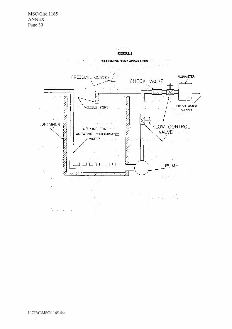
MSC/Circ.1165 ANNEX Page 30
I:\CIRC\MSC\1165.doc
MSC/Circ.1165 ANNEX Page 31
I:\CIRC\MSC\1165.doc
APPENDIX B
TEST METHOD FOR FIRE TESTING EQUIVALENT WATER-BASED FIRE-EXTINGUISHING SYSTEMS FOR MACHINERY SPACES
OF CATEGORY A AND CARGO PUMP-ROOMS 1 SCOPE 1.1 This test method is intended for evaluating the extinguishing effectiveness of water-based total flooding fire-extinguishing systems for the protection of engine-rooms of category A and cargo pump-rooms. 1.2 The test method covers the minimum fire-extinguishing requirement and prevention against reignition for fires in engine-rooms. 1.3 It was developed for systems using ceiling mounted nozzles or multiple levels of nozzles. Bilge nozzles are required for all systems. The bilge nozzles may be part of the main system, or they may be a separate bilge area protection system. 1.4 In the tests, the use of additional nozzles to protect specific hazards by direct application is not permitted. However for ship board applications additional nozzles may be added as recommended by the manufacturer. 2 FIELD OF APPLICATION The test method is applicable for water-based fire-extinguishing systems which will be used as alternative fire-extinguishing systems as required by SOLAS regulation II-2/10.4.1 and II-2/10.9.1. For the installation of the system, nozzles shall be installed to protect the entire hazard volume (total flooding). The installation specification provided by the manufacturer should include maximum horizontal and vertical nozzle spacing, maximum enclosure height, and distance of nozzles below the ceiling and maximum enclosure volume which, as a principle, should not exceed the values used in approval fire test. However, when based on the scientific methods developed by the Organization*, scaling from the maximum tested volume to a larger volume may be permitted. The scaling should not exceed twice the tested volume. 3 SAMPLING The components to be tested should be supplied by the manufacturer together with design and installation criteria, operational instructions, drawings and technical data sufficient for the identification of the components.
* To be developed by the Organization.

MSC/Circ.1165 ANNEX Page 32
I:\CIRC\MSC\1165.doc
4 METHOD OF TEST
4.1 Principle This test procedure enables the determination of the effectiveness of different water-based extinguishing systems against spray fires, cascade fires, pool fires, and Class A fires which are obstructed by an engine mock-up. 4.2 Apparatus 4.2.1 Engine mock-up The fire test should be performed in a test apparatus consisting of:
.1 an engine mock-up of the size (width × length × height) of 1 m × 3 m × 3 m constructed of sheet steel with a nominal thickness of 5 mm. The mock-up is fitted with two steel tubes of 0.3 m in diameter and 3 m in length that simulate exhaust manifolds and a grating. At the top of the mock-up, a 3 m2 tray is arranged (see figure 1); and
.2 a floor plate system of the size (width × length × height) of 4 m × 6 m × 0.5 m,
surrounding the mock-up. Provision shall be made for placement of the fuel trays, described in table 1, and located as described in figure 1.
4.2.2 Fire test compartment The tests should be performed in a room having a specified area greater than 100 m2, a specified height of at least 5 m and ventilation through a door opening of 2 m × 2 m in size. Fires and engine mock-up should be according to tables 1, 2, 3 and figure 2. The test hall should have an ambient temperature of between 10°C and 30°C at the start of each test.

MSC/Circ.1165 ANNEX Page 33
I:\CIRC\MSC\1165.doc
Figure 1
NS300
NS300

MSC/Circ.1165 ANNEX Page 34
I:\CIRC\MSC\1165.doc
Figure 2
4000
500
500
4000
Thermocouple tree (2) Thermocouple tree (1)
Mid-height
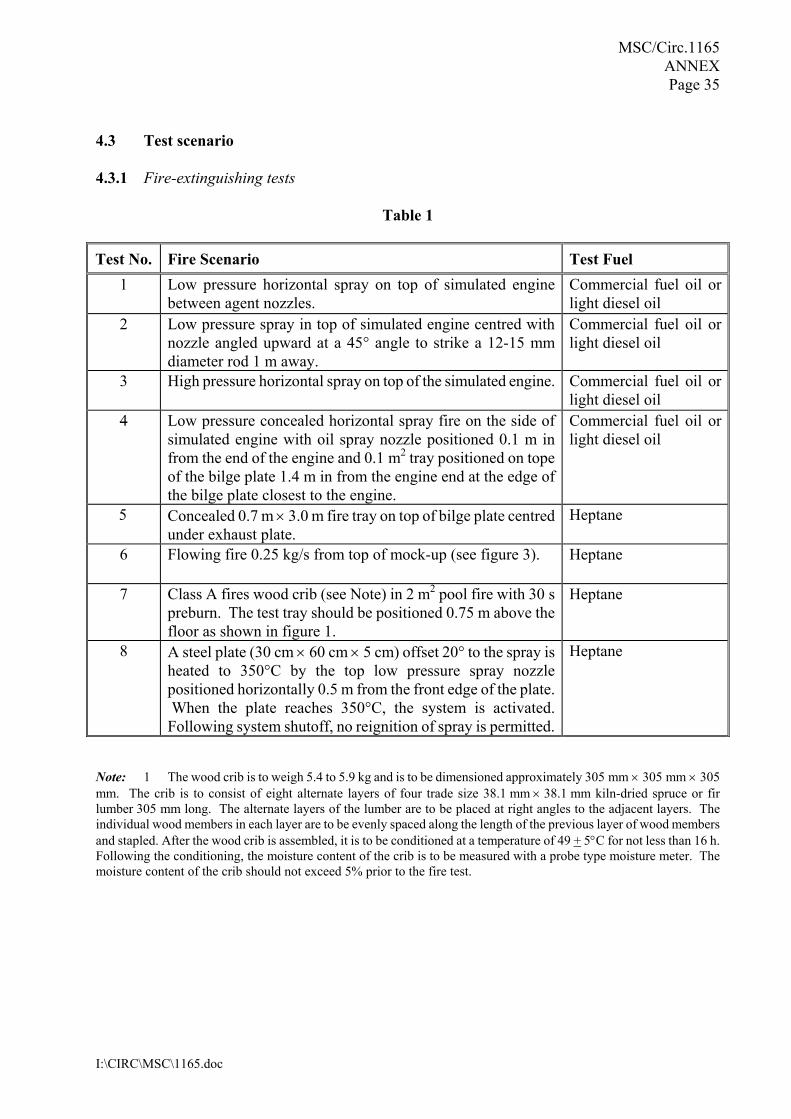
MSC/Circ.1165 ANNEX Page 35
I:\CIRC\MSC\1165.doc
4.3 Test scenario 4.3.1 Fire-extinguishing tests
Table 1 Test No. Fire Scenario Test Fuel
1 Low pressure horizontal spray on top of simulated engine between agent nozzles.
Commercial fuel oil or light diesel oil
2 Low pressure spray in top of simulated engine centred with nozzle angled upward at a 45° angle to strike a 12-15 mm diameter rod 1 m away.
Commercial fuel oil or light diesel oil
3 High pressure horizontal spray on top of the simulated engine. Commercial fuel oil or light diesel oil
4 Low pressure concealed horizontal spray fire on the side of simulated engine with oil spray nozzle positioned 0.1 m in from the end of the engine and 0.1 m2 tray positioned on tope of the bilge plate 1.4 m in from the engine end at the edge of the bilge plate closest to the engine.
Commercial fuel oil or light diesel oil
5 Concealed 0.7 m × 3.0 m fire tray on top of bilge plate centred under exhaust plate.
Heptane
6 Flowing fire 0.25 kg/s from top of mock-up (see figure 3). Heptane
7 Class A fires wood crib (see Note) in 2 m2 pool fire with 30 s preburn. The test tray should be positioned 0.75 m above the floor as shown in figure 1.
Heptane
8 A steel plate (30 cm × 60 cm × 5 cm) offset 20° to the spray is heated to 350°C by the top low pressure spray nozzle positioned horizontally 0.5 m from the front edge of the plate. When the plate reaches 350°C, the system is activated. Following system shutoff, no reignition of spray is permitted.
Heptane
Note: 1 The wood crib is to weigh 5.4 to 5.9 kg and is to be dimensioned approximately 305 mm × 305 mm × 305 mm. The crib is to consist of eight alternate layers of four trade size 38.1 mm × 38.1 mm kiln-dried spruce or fir lumber 305 mm long. The alternate layers of the lumber are to be placed at right angles to the adjacent layers. The individual wood members in each layer are to be evenly spaced along the length of the previous layer of wood members and stapled. After the wood crib is assembled, it is to be conditioned at a temperature of 49 + 5°C for not less than 16 h. Following the conditioning, the moisture content of the crib is to be measured with a probe type moisture meter. The moisture content of the crib should not exceed 5% prior to the fire test.
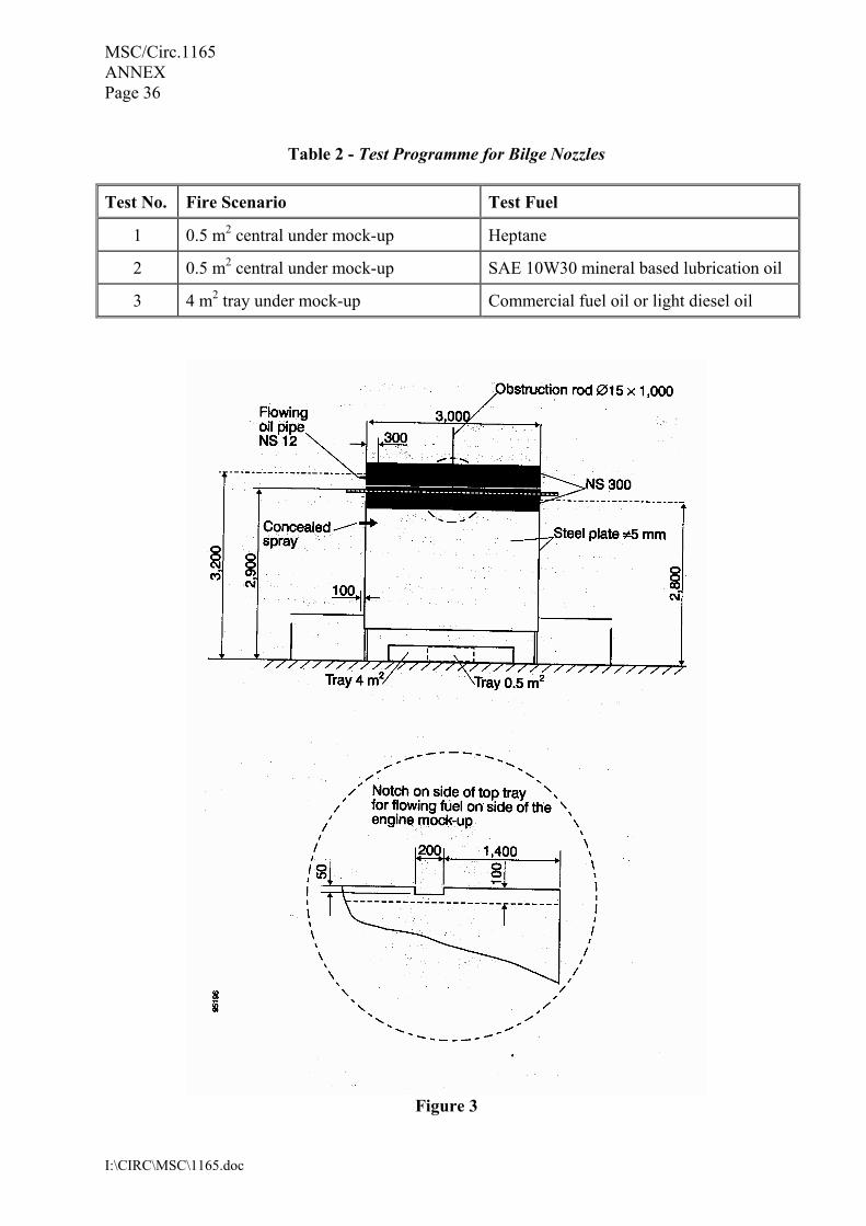
MSC/Circ.1165 ANNEX Page 36
I:\CIRC\MSC\1165.doc
Table 2 - Test Programme for Bilge Nozzles
Test No. Fire Scenario Test Fuel
1 0.5 m2 central under mock-up Heptane
2 0.5 m2 central under mock-up SAE 10W30 mineral based lubrication oil
3 4 m2 tray under mock-up Commercial fuel oil or light diesel oil
Figure 3
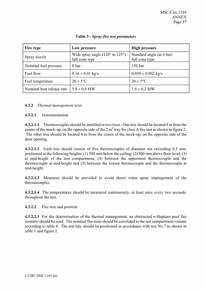
MSC/Circ.1165 ANNEX Page 37
I:\CIRC\MSC\1165.doc
Table 3 - Spray fire test parameters
Fire type Low pressure High pressure
Spray nozzle Wide spray angle (120° to 125°) full cone type
Standard angle (at 6 bar) full cone type
Nominal fuel pressure 8 bar 150 bar
Fuel flow 0.16 ± 0.01 kg/s 0.050 ± 0.002 kg/s
Fuel temperature 20 ± 5°C 20 ± 5°C
Nominal heat release rate 5.8 ± 0.6 MW 1.8 ± 0.2 MW 4.3.2 Thermal management tests 4.3.2.1 Instrumentation 4.3.2.1.1 Thermocouples should be installed in two trees. One tree should be located 4 m from the centre of the mock-up, on the opposite side of the 2 m2 tray for class A fire test as shown in figure 2. The other tree should be located 4 m from the centre of the mock-up, on the opposite side of the door opening. 4.3.2.1.2 Each tree should consist of five thermocouples of diameter not exceeding 0.5 mm, positioned at the following heights: (1) 500 mm below the ceiling; (2) 500 mm above floor level; (3) at mid-height of the test compartment; (4) between the uppermost thermocouple and the thermocouple at mid-height and (5) between the lowest thermocouple and the thermocouple at mid-height. 4.3.2.1.3 Measures should be provided to avoid direct water spray impingement of the thermocouples. 4.3.2.1.4 The temperatures should be measured continuously, at least once every two seconds, throughout the test. 4.3.2.2 Fire size and position 4.3.2.2.1 For the determination of the thermal management, an obstructed n-Heptane pool fire scenario should be used. The nominal fire sizes should be correlated to the test compartment volume according to table 4. The test tray should be positioned in accordance with test No.7 as shown in table 1 and figure 2.

MSC/Circ.1165 ANNEX Page 38
I:\CIRC\MSC\1165.doc
Table 4 - Correlation between nominal pool fire sizes and test compartment volume
Test compartment volume
Pool fire scenario
500 m3 1 MW 1000 m3 2 MW 1500 m3 3 MW 2000 m3 4 MW 2500 m3 5 MW 3000 m3 6 MW
Note: Interpolation of the data in the table is allowed.
4.3.2.2.2 The rim height of the trays should be 150 mm and the tray should be filled with 50 mm of fuel. Additional water should be added to provide a freeboard of 50 mm. Table 5 provides examples of pool tray diameters and the corresponding area, for a selection of nominal heat release rates.
Table 5 - Pool tray diameters and the corresponding area, for a selection of nominal heat release rates
Nominal
HRR Diameter
(cm) Area (m2)
Size of obstruction steel
plate (m x m) 0.5 MW 62 0.30 2.0 x 2.0 1 MW 83 0.54 2.0 x 2.0 2 MW 112 0.99 2.0 x 2.0 3 MW 136 1.45 2.25 x 2.25 4 MW 156 1.90 2.25 x 2.25 5 MW 173 2.36 2.5 x 2.5 6 MW 189 2.81 2.5 x 2.5
Note: Interpolation or extrapolation of the data is allowed according to the following equation:
Q = 2.195A−0.18
where:
Q = the desired nominal heat release rate (MW) A = the area of the fire tray (m2)
4.3.2.2.3 A square horizontal obstruction steel plate should shield the pool fire tray from direct water spray impingement. The size of the obstruction steel plate is dictated by the size of the fire tray, as indicated in table 5. The vertical distance measured from the floor to the underside of the obstruction steel plate should be 1.0 m. 4.3.2.2.4 The thickness of the steel plate should be a nominal 4 mm. The vertical distance measured from the rim of the trays to the underneath of the horizontal obstruction steel plate should be 0.85 m.

MSC/Circ.1165 ANNEX Page 39
I:\CIRC\MSC\1165.doc
4.4 Extinguishing system 4.4.1 During fire test conditions the extinguishing system should be installed according to the manufacturer's design and installation instructions in a uniformly spaced overhead nozzle grid. The lowest level of nozzles should be located at least 5 m above the floor. For actual installations, if the water-mist system includes bilge area protection, water-mist nozzles must be installed throughout the bilges in accordance with the manufacturer�s recommended dimensioning, as developed from bilge system testing using the tests in table 2, conducted with the bilge plate located at the maximum height for which approval is sought. Tests should be performed with nozzles located in the highest and lowest recommended position above the bilge fires. Bilge systems using the nozzle spacing tested may be approved for fire protection of bilge areas of any size. 4.4.2 The system fire tests should be conducted at the minimum system operating pressure, or at the conditions providing the minimum water application rate. 4.4.3 During the laboratory fire tests the bilge system nozzles may not be located beneath the engine mock-up, but should be located beneath the simulated bilge plates at least one-half the nozzle spacing away from the engine mock-up. 4.5 Procedure 4.5.1 Ignition The trays used in the test should be filled with at least 50 mm fuel on a water base. Freeboard is to be 150±10 mm. 4.5.2 Flow and pressure measurements (Fuel system) The fuel flow and pressure in the fuel system should be measured before each test. The fuel pressure should be measured during the test. 4.5.3 Flow and pressure measurements (Extinguishing system) Agent flow and pressure in the extinguishing system should be measured continuously on the high pressure side of a pump or equivalent equipment at intervals not exceeding 5 s during the test, alternatively, the flow can be determined by the pressure and the K factor of the nozzles. 4.5.4 Duration of test 4.5.4.1 After ignition of all fuel sources, a 2-min preburn time is required before the extinguishing agent is discharged for the fuel tray fires and 5-15 s for the fuel spray and heptane fires and 30 s for the Class A fire test (Test No.7). 4.5.4.2 The fire should be allowed to burn until the fire is extinguished or for a period of 15 minutes, whichever is less, measured from the ignition. The fuel spray, if used, should be shut off 15 s after the end of agent discharge. 4.5.5 Observations before and during the test 4.5.5.1 Before the test, the test room, fuel and mock-up temperature is to be measured.

MSC/Circ.1165 ANNEX Page 40
I:\CIRC\MSC\1165.doc
4.5.5.2 During the test the following items should be recorded: .1 the start of the ignition procedure; .2 the start of the test (ignition); .3 the time when the extinguishing system is activated; .4 the time when the fire is extinguished, if it is; .5 the time when the extinguishing system is shut off; .6 the time of re-ignition, if any; .7 the time when the oil flow for the spray fire is shut off; .8 the time when the test is finished; and .9 data from all test instrumentation. 4.5.6 Observations after the test
.1 damage to any system components; .2 the level of fuel in the tray(s) to make sure that the fuel was not totally consumed; and .3 test room, fuel and mock-up temperature.
5 CLASSIFICATION CRITERIA 5.1 Fire-extinguishing tests All fires in the fire-extinguishing tests should be extinguished within 15 minutes of system activation and there should be no re-ignition or fire spread. 5.2 Thermal management tests The 60 s time-weighted average temperature should be kept below 100°C, no later than 300 s after activation of the system for the thermal management test in 4.3.2. 6 TEST REPORT The test report should include the following information:
.1 name and address of the test laboratory; .2 date and identification number of the test report; .3 name and address of client;
MSC/Circ.1165 ANNEX Page 41
I:\CIRC\MSC\1165.doc
.4 purpose of the test; .5 method of sampling; .6 name and address of manufacturer or supplier of the product; .7 name or other identification marks of the product; .8 description of the tested product:
� drawings, � descriptions, � assembly instructions, � specification of included materials, and � detailed drawing of test set-up;
.9 date of supply of the product; .10 date of test; .11 test method; .12 drawing of each test configuration; .13 measured nozzle characteristics; .14 identification of the test equipment and used instruments; .15 conclusions; .16 deviations from the test method, if any; .17 test results including observations during and after the test; and .18 date and signature.
_______________
I:\CIRC\MSC\1168.doc
INTERNATIONAL MARITIME ORGANIZATION 4 ALBERT EMBANKMENT LONDON SE1 7SR Telephone: 020 7587 3152 Fax: 020 7587 3210
IMO
E
Ref. T4/4.01 MSC/Circ.1168 1 June 2005 INTERIM GUIDELINES FOR THE TESTING, APPROVAL AND MAINTENANCE OF
EVACUATION GUIDANCE SYSTEMS USED AS AN ALTERNATIVE TO LOW-LOCATION LIGHTING SYSTEMS
1 The Maritime Safety Committee, at its seventy-fifth session (15 to 24 May 2002), recognized the need for the development of guidelines for the testing, approval and maintenance of evacuation guidance systems used as an alternative to low-location lighting systems required by SOLAS chapter II-2 and the FSS Code. 2 The Committee, at its eightieth session (11 to 20 May 2005), having considered a proposal by the forty-ninth session of the Sub-Committee on Fire Protection, approved the Interim Guidelines for the testing, approval and maintenance of evacuation guidance systems alternative to the low-location lighting systems, set out in the annex. 3 Member Governments are invited to apply the annexed Interim Guidelines and submit to the Sub-Committee on Fire Protection information on experience gained in the implementation of the Interim Guidelines and on any progress made in the development of the testing, approval and maintenance of evacuation guidance systems. 4 Member Governments are also invited to bring the annexed Interim Guidelines to the attention of ship designers, shipowners, ship operators, shipbuilders and other parties involved in the design, construction, testing, approval and maintenance of evacuation guidance systems.
***


MSC/Circ.1168
I:\CIRC\MSC\1168.doc
ANNEX INTERIM GUIDELINES FOR THE TESTING, APPROVAL AND MAINTENANCE OF
EVACUATION GUIDANCE SYSTEMS USED AS AN ALTERNATIVE TO LOW-LOCATION LIGHTING SYSTEMS
1 Scope The purpose of these Guidelines is to provide standards for the testing, approval and maintenance for alternative systems to low-location lighting systems required by SOLAS regulation II-2/13.3.2.5.1 and chapter 11 of the FSS Code. 2 Testing 2.1 Test for corridors should be performed in reduced visibility using theatrical (white) smoke with an Optical Density at least OD 0.5 m-1∗. Measuring equipment should conform to a standard acceptable to the Administration. 2.2 If the system is to be installed in public spaces, the test should be performed in reduced visibility using theatrical (white) smoke with an Optical Density at least OD 0.1 m-1. 2.3 Test for stairway enclosures should be performed in clear (no smoke) conditions. 2.4 A minimum 80% of the participants should reach the pre-designated exit with a speed of movement of at least 0.7 m/s calculated using the distance measurement of the optimum route. Participants achieving a speed of movement of less than 0.7 m/s should be deemed to have failed. There is no speed of movement criterion applied to stairway enclosure tests. 2.5 The maximum percentage of participants choosing failed exits should not exceed the value of 2% for public spaces and 5% for accommodation areas, corridors and stairway enclosures. 2.6 In the public space configuration when testing with two correct exits, no more than 15% of the participants may choose the more distant exit. 2.7 There should be a minimum of 60 participants for each test - being at least 8 and not more than 12 of each age group 16-25, 26-35, 36-45, 46-55, 56-65, 66-75 with an average of 45-55% male/female of the entire group. 2.8 A �control� test should be performed with no guidance system in operation in order to demonstrate that there is no significant inherent bias to favour the pre-designated exit. Participants of the �control� test should not participate in any previous or subsequent tests. 2.9 For the purpose of this section:
.1 a �correct exit� is an exit to which the evacuation guidance system intentionally guides participants;
∗ Refer to the United Kingdom Government�s Health and Safety Executive (HSE) 1998 report: OTH 533 Emergency
Way Guidance Lighting Systems (http://www.hse.gov.uk/research/othpdf/500-599/oth533.pdf).

MSC/Circ.1168 ANNEX Page 2
I:\CIRC\MSC\1168.doc
.2 participants arriving at any of the �fail exits� are deemed to have �failed� the test and
should be stopped at that point;
.3 only one participant should be in the test at a time in order to preclude any crowd behavioural influence;
.4 the test area should be illuminated by the emergency lighting as required by SOLAS;
and
.5 during the test signage other than those being part of the test should not be used. 3 Test facility design 3.1 Public spaces 3.1.1 If the system is intended to be installed in public spaces, the test facility should be designed so that participants are required to navigate to a pre-designated exit across a public space, where the shortest distance to that exit is not along a wall. A minimum of two exits should be provided to test the ability of participants to identify and proceed to an exit within an open space. An additional fail exit should be located 2 to 3 m from each correct exit. 3.1.2 The test room should be not less than 15 m by 10 m with the start point and pre-designated exit being on the long sides, diagonally opposite each other, such that the distance around the walls is approximately equal in either direction. The density of the smoke should be great enough to prevent a participant from being able to see no more than half to two-thirds of the distance to the nearest exit OD 0.1 m-1. Direct distance between start and a correct exit should be not less than 12 m. 3.2 Accommodation areas and corridors The test layout should be such that participants should be required to navigate correctly their way to a pre-designated exit via at least four decision points including at least two cross-junctions and at least one T-junction. It should not be possible to navigate the correct route by remaining attached to one continuous wall. The correct route should include the placement of a non-exit door within 2 to 3 m of the correct exit door. A non-exit door is a fail exit. The total distance travelled over the correct route should be not less than 25 m, with the distance between decision points being not less than 5 m. 3.3 Stairway enclosures Participants should be required to use the stairway enclosures to a pre-designated floor. The participants should enter the stairway enclosures from a mid-point where each will be instructed by the guidance system to proceed either up or down. The option of up or down should be randomly chosen. 4 Participant briefing Participants to be briefed on the purpose of the test and the technology to be tested, using the proposed briefing technique that would be used in the implementation on board ship, e.g. the briefing
MSC/Circ.1168 ANNEX
Page 3
I:\CIRC\MSC\1168.doc
given during lifeboat drill, instructions on backs of cabin doors or via the ship�s public address system, etc. No briefing should be given on the route, test layout or numbers of exits. 5 Approval All systems should be approved by the Administration for compliance with the Performance standards for evacuation guidance systems (MSC/Circ.1167) developed by the Organization and, for electrically powered systems, IEC 60092 Electrical Installations in Ships. Installation requirements should be included in the approval procedures, and individual onboard arrangements should be verified accordingly. 6 Maintenance 6.1 All elements of the system should be visually examined and checked at least once per week, and a record thereof should be kept. All missing, damaged or inoperable elements should be replaced. 6.2 All systems should have their signal tested at least once every five years. Readings should be taken on site. Should any reading be found to be outside manufacturer�s tolerances, then that element of the system should be replaced.
__________