f/t sensor data acquisition (daq) systemsdata acquisition (daq) systems manual document #:...
TRANSCRIPT
Engineered Products for Robotic ProductivityPinnacle Park • 1031 Goodworth Drive • Apex, NC 27539 • Tel: +1-919.772.0115 • Fax: +1-919.772.8259 • www.ati-ia.com • Email: [email protected]
F/T Sensor Data Acquisition (DAQ) Systems
Manual
Document #: 9620-05-DAQ.indd
Manual, F/T Sensor, Data Acquisition (DAQ) SystemsDocument #9620-05-DAQ.indd-20
Pinnacle Park • 1031 Goodworth Drive • Apex, NC 27539 • Tel: 919.772.0115 • Fax: 919.772.8259 • www.ati-ia.com • Email: [email protected] 2
ForewordInformation contained in this document is the property of ATI Industrial Automation, Inc. and shall not be reproduced in whole or in part without prior written approval of ATI Industrial Automation, Inc. The information herein is subject to change without notice and should not be construed as a commitment on the part of ATI Industrial Automation, Inc. This manual is periodically revised to reflect and incorporate changes made to the F/T system.
ATI Industrial Automation, Inc. assumes no responsibility for any errors or omissions in this document. Users’ critical evaluation is welcome to assist in the preparation of future.
Copyright © by ATI Industrial Automation, Inc., Apex, North Carolina USA. All Rights Reserved. Published in the USA.
In consideration that ATI Industrial Automation, Inc. (ATI) products are intended for use with robotic and/or automated machines, ATI does not recommend the use of its products for applications wherein failure or malfunction of a ATI component or system threatens life or makes injury probable. Anyone who uses or incorporates ATI components within any potentially life threatening system must obtain ATI’s prior consent based upon assurance to ATI that a malfunction of ATI’s component does not pose direct or indirect threat of injury or death, and (even if such consent is given) shall indemnify ATI from any claim, loss, liability, and related expenses arising from any injury or death resulting from use of ATI components.
All trademarks belong to their respective owners. Windows, Visual Basic and Excel are registered trademarks of Microsoft Corporation. LabVIEW is a registered trademark of National Instruments Corporation.
NOTICE: Please read the manual before calling customer service. Before calling, have the following information available.
1. Serial number (e.g., FT01234)2. Transducer model (e.g., Nano17, Gamma, Theta, etc.)3. Calibration (e.g., US-15-50, SI-65-6, etc.)4. Accurate and complete description of the question or problem5. Computer and software information. Operating system, PC type, drivers, application software,
and other relevant information about your configuration.If possible, be near the F/T system when calling.
How to Reach Us
Sale, Service and Information about ATI products:
ATI Industrial Automation 1031 Goodworth Drive Apex, NC 27539 USA www.ati-ia.com Tel: +1.919.772.0115 Fax: +1.919.772.8259 E-mail: [email protected]
Technical support and questions:Application Engineering Tel: +1.919.772.0115, Option 2, Option 2 Fax: +1.919.772.8259 E-mail: [email protected]
Manual, F/T Sensor, Data Acquisition (DAQ) SystemsDocument #9620-05-DAQ.indd-20
Pinnacle Park • 1031 Goodworth Drive • Apex, NC 27539 • Tel: 919.772.0115 • Fax: 919.772.8259 • www.ati-ia.com • Email: [email protected] 3
Table of ContentsForeword .......................................................................................................................................... 2Glossary ........................................................................................................................................... 61. Safety ......................................................................................................................................... 7
1.1 ExplanationofNotifications ......................................................................................................... 7
1.2 General Safety Guidelines ............................................................................................................ 7
1.3 Safety Precautions ........................................................................................................................ 7
2. Product Overview ..................................................................................................................... 82.1 System with a TW Transducer, IFPS Box, and USB DAQ Device ............................................. 8
2.2 System with a TIF Transducer, PS Box, and DAQ Card ............................................................. 9
2.3 System with Multiple Transducers, IFPSMC Box, and a USB DAQ Device ........................... 10
2.4 System with Multiple Transducers, IFPSMC Box, and a DAQ Card ....................................... 11
2.5 System with Multiple Transducers, IFPSMC Box, Wired I/O Connections for User Devices, and USB DAQ Device ......................................................................................... 12
2.6 Transducer ................................................................................................................................... 13
2.7 Transducer Cable ........................................................................................................................ 13
2.8 Interface Power Supply Box ....................................................................................................... 14
2.9 Power Supply Box ....................................................................................................................... 15
2.10 Power Supply Cable .................................................................................................................... 15
2.11 Multiple IFPSMC Boxes .............................................................................................................. 16
2.12 DAQ Shielded Cables from Multiple IFPSMC Box to DAQ Device .......................................... 16
2.13 Data Acquisition System ............................................................................................................ 17
2.14 F/T Software CD ........................................................................................................................... 17
2.15 Interface Plates ............................................................................................................................ 17
3. System Functionality ............................................................................................................. 183.1 Mechanical Description .............................................................................................................. 18
3.2 Electronic Hardware .................................................................................................................... 19
3.3 Load Calculation ......................................................................................................................... 203.3.1 Strain Gage Data .............................................................................................................. 20
3.3.2 Offset Correction .............................................................................................................. 21
3.3.3 Calibration Matrix ............................................................................................................. 21
3.3.4 Gain Correction Factor ..................................................................................................... 21
3.4 ATI DAQ Software ........................................................................................................................ 223.4.1 Reusable Software Components ...................................................................................... 22
3.4.1.1 ATI DAQ FT Automation Server ........................................................................ 223.4.1.2 C Library ........................................................................................................... 22
3.4.2 Sample Applications ......................................................................................................... 22

Manual, F/T Sensor, Data Acquisition (DAQ) SystemsDocument #9620-05-DAQ.indd-20
Pinnacle Park • 1031 Goodworth Drive • Apex, NC 27539 • Tel: 919.772.0115 • Fax: 919.772.8259 • www.ati-ia.com • Email: [email protected] 4
3.4.2.1 Windows Demo (Visual Basic 6.0) .................................................................... 223.4.2.2 LabVIEW Sample ............................................................................................. 22
3.4.3 Designing Your DAQ F/T Application ................................................................................ 233.4.3.1 Device Drivers for Your DAQ Device and Target Operating System................. 233.4.3.2 ATI DAQ F/T Components or C Library ............................................................ 23
4. Installation .............................................................................................................................. 244.1 Installing a DAQ System with a Transducer, IFPS or PS Box, and DAQ Device ................... 24
4.2 Installing a DAQ System with Multiple Transducers, IFPSMC Box, and DAQ Device .......... 29
4.3 Installing a DAQ System with Multiple Transducers, IFPSMC Box, Wired I/O Connections, and USB DAQ Device ......................................................................... 32
4.4 Install the F/T Demo Software .................................................................................................... 34
4.5 Electrical Connection Information ............................................................................................. 364.5.1 Signals and Power ........................................................................................................... 36
4.5.2 Electrical Specifications .................................................................................................... 374.5.2.1 Transducer Output Signals ............................................................................... 37
4.5.3 Transducer Signals ........................................................................................................... 38
4.5.4 PS and IFPS Signals ........................................................................................................ 394.5.4.1 PS 20-pin Circular Connector ........................................................................... 394.5.4.2 PS and IFPS 26-pin High Density D-Subminiature Connector ......................... 39
4.5.5 DAQ Card Connections .................................................................................................... 404.5.5.1 Standard DAQ Card Connections ..................................................................... 404.5.5.2 Custom DAQ Card Connections ....................................................................... 414.5.5.3 Using Unused DAQ Card Resources ............................................................... 43
4.5.6 Transducer Connections on a Multi-Sensor IFPSMC Box ............................................... 434.5.6.1 Installing 12 Pin Jumpers on the Backplane to Make Unused
Transducer Signals Available to the User ......................................................... 454.5.6.2 Installing Additional IFPS Cards in an IFPSMC Box ......................................... 514.5.6.3 Power ................................................................................................................ 55
5. Operation ................................................................................................................................ 565.1 Writing DAQ F/T Application ...................................................................................................... 56
5.2 Data Collection Rates ................................................................................................................. 56
5.3 Multiple Calibrations ................................................................................................................... 56
5.4 Resolution .................................................................................................................................... 56
5.5 Environmental ............................................................................................................................. 57
6. Maintenance ............................................................................................................................ 586.1 Periodic Inspection ..................................................................................................................... 58
6.2 Periodic Calibration .................................................................................................................... 58
6.3 Multiple IFPSMC Box Recalibration ........................................................................................... 586.3.1 Removing and Replacing the IFPS Card for Recalibration .............................................. 59

Manual, F/T Sensor, Data Acquisition (DAQ) SystemsDocument #9620-05-DAQ.indd-20
Pinnacle Park • 1031 Goodworth Drive • Apex, NC 27539 • Tel: 919.772.0115 • Fax: 919.772.8259 • www.ati-ia.com • Email: [email protected] 5
7. Troubleshooting ..................................................................................................................... 627.1 Errors with Force and Torque Readings ................................................................................... 63
7.2 Detecting Failures (Diagnostics) ............................................................................................... 647.2.1 Detecting Connection Issues ............................................................................................ 64
7.2.2 Detecting Cable Problems ................................................................................................ 64
7.2.3 Detecting Sensitivity Changes .......................................................................................... 64
8. Regulatory Information .......................................................................................................... 658.1 Electromagnetic Compatibility ................................................................................................... 65
8.2 RoHS Compliance ....................................................................................................................... 65
8.3 Safety Standards ......................................................................................................................... 65
9. Drawings ................................................................................................................................. 669.1 9105-PS-1 – DAQ Power Supply ................................................................................................ 66
9.2 9105-IFPS-1 – DAQ Interface Power Supply ............................................................................. 67
9.3 9105-IFPSMC Multiple IFPS Box ................................................................................................ 68
10. Terms and Conditions of Sale ............................................................................................... 69Appendix A – Tool Transformation .............................................................................................. 70
Manual, F/T Sensor, Data Acquisition (DAQ) SystemsDocument #9620-05-DAQ.indd-20
Pinnacle Park • 1031 Goodworth Drive • Apex, NC 27539 • Tel: 919.772.0115 • Fax: 919.772.8259 • www.ati-ia.com • Email: [email protected] 6
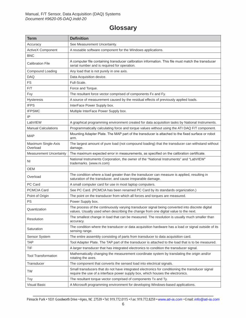
GlossaryTerm DefinitionAccuracy See Measurement Uncertainty.
ActiveX Component A reusable software component for the Windows applications.
BNC
Calibration File A computer file containing transducer calibration information. This file must match the transducer serial number and is required for operation.
Compound Loading Any load that is not purely in one axis.
DAQ Data Acquisition device.
FS Full-Scale.
F/T Force and Torque.
Fxy The resultant force vector comprised of components Fx and Fy.
Hysteresis A source of measurement caused by the residual effects of previously applied loads.
IFPS InterFace Power Supply box.
IFPSMC Multiple InterFace Power Supply box.
IP
LabVIEW A graphical programming environment created for data acquisition tasks by National Instruments.
Manual Calculations Programmatically calculating force and torque values without using the ATI DAQ F/T component.
MAP Mounting Adapter Plate. The MAP part of the transducer is attached to the fixed surface or robot arm.
Maximum Single-Axis Overload
The largest amount of pure load (not compound loading) that the transducer can withstand without damage.
Measurement Uncertainty The maximum expected error in measurements, as specified on the calibration certificate.
NI National Instruments Corporation, the owner of the “National Instruments” and “LabVIEW” trademarks. (www.ni.com)
OEM
Overload The condition where a load greater than the transducer can measure is applied, resulting in saturation of the transducer, and cause irreparable damage.
PC Card A small computer card for use in most laptop computers.
PCMCIA Card See PC Card. (PCMCIA has been renamed PC Card by its standards organization.)
Point of Origin The point on the transducer from which all forces and torques are measured.
PS Power Supply box.
Quantization The process of the continuously varying transducer signal being converted into discrete digital values. Usually used when describing the change from one digital value to the next.
Resolution The smallest change in load that can be measured. The resolution is usually much smaller than accuracy.
Saturation The condition where the transducer or data acquisition hardware has a load or signal outside of its sensing range.
Sensor System The entire assembly consisting of parts from transducer to data acquisition card.
TAP Tool Adapter Plate. The TAP part of the transducer is attached to the load that is to be measured.
TIF A larger transducer that has integrated electronics to condition the transducer signal.
Tool Transformation Mathematically changing the measurement coordinate system by translating the origin and/or rotating the axes.
Transducer The component that converts the sensed load into electrical signals.
TW Small transducers that do not have integrated electronics for conditioning the transducer signal require the use of a interface power supply box, which houses the electronics.
Txy The resultant torque vector comprised of components Tx and Ty.
Visual Basic A Microsoft programming environment for developing Windows-based applications.
Manual, F/T Sensor, Data Acquisition (DAQ) SystemsDocument #9620-05-DAQ.indd-20
Pinnacle Park • 1031 Goodworth Drive • Apex, NC 27539 • Tel: 919.772.0115 • Fax: 919.772.8259 • www.ati-ia.com • Email: [email protected] 7
1. SafetyThe safety section describes general safety guidelines to be followed with this product, explanations of the notifications found in this manual, and safety precautions that apply to the product. More specific notifications are imbedded within the sections of the manual where they apply.
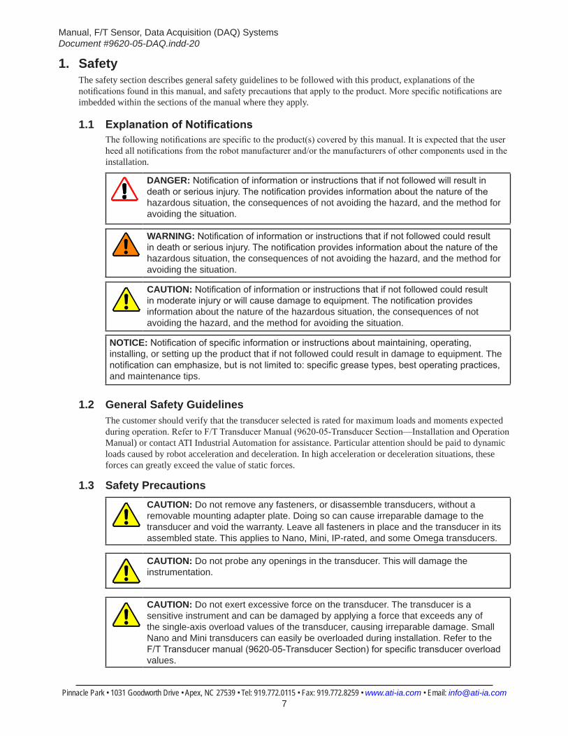
1.1 ExplanationofNotificationsThe following notifications are specific to the product(s) covered by this manual. It is expected that the user heed all notifications from the robot manufacturer and/or the manufacturers of other components used in the installation.
DANGER: Notification of information or instructions that if not followed will result in death or serious injury. The notification provides information about the nature of the hazardous situation, the consequences of not avoiding the hazard, and the method for avoiding the situation.
WARNING: Notification of information or instructions that if not followed could result in death or serious injury. The notification provides information about the nature of the hazardous situation, the consequences of not avoiding the hazard, and the method for avoiding the situation.
CAUTION: Notification of information or instructions that if not followed could result in moderate injury or will cause damage to equipment. The notification provides information about the nature of the hazardous situation, the consequences of not avoiding the hazard, and the method for avoiding the situation.
NOTICE: Notification of specific information or instructions about maintaining, operating, installing, or setting up the product that if not followed could result in damage to equipment. The notification can emphasize, but is not limited to: specific grease types, best operating practices, and maintenance tips.
1.2 General Safety GuidelinesThe customer should verify that the transducer selected is rated for maximum loads and moments expected during operation. Refer to F/T Transducer Manual (9620-05-Transducer Section—Installation and Operation Manual) or contact ATI Industrial Automation for assistance. Particular attention should be paid to dynamic loads caused by robot acceleration and deceleration. In high acceleration or deceleration situations, these forces can greatly exceed the value of static forces.
1.3 Safety PrecautionsCAUTION: Do not remove any fasteners, or disassemble transducers, without a removable mounting adapter plate. Doing so can cause irreparable damage to the transducer and void the warranty. Leave all fasteners in place and the transducer in its assembled state. This applies to Nano, Mini, IP-rated, and some Omega transducers.
CAUTION: Do not probe any openings in the transducer. This will damage the instrumentation.
CAUTION: Do not exert excessive force on the transducer. The transducer is a sensitive instrument and can be damaged by applying a force that exceeds any of the single-axis overload values of the transducer, causing irreparable damage. Small Nano and Mini transducers can easily be overloaded during installation. Refer to the F/T Transducer manual (9620-05-Transducer Section) for specific transducer overload values.
Manual, F/T Sensor, Data Acquisition (DAQ) SystemsDocument #9620-05-DAQ.indd-20
Pinnacle Park • 1031 Goodworth Drive • Apex, NC 27539 • Tel: 919.772.0115 • Fax: 919.772.8259 • www.ati-ia.com • Email: [email protected] 8
2. Product OverviewThe DAQ Force/Torque sensor system is a multi-axis force and torque sensor system that simultaneously measures forces (Fx, Fy, and Fz) and torques (Tx, Ty, and Tz). Components are available for Single TW Transducer DAQ Systems, TIF Transducer DAQ Systems, and Multiple TW Transducer DAQ Systems. Other equipment is available such as rack mounted equipment, BNC interface boxes, IP rated Transducers, IP rated cables, OEM interface boards, cable extensions, and many DAQ device and card options.
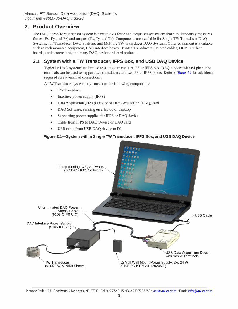
2.1 System with a TW Transducer, IFPS Box, and USB DAQ DeviceTypically DAQ systems are limited to a single transducer, PS or IFPS box. DAQ devices with 64 pin screw terminals can be used to support two transducers and two PS or IFPS boxes. Refer to Table 4.1 for additional required screw terminal connections. A TW Transducer system may consist of the following components:
• TW Transducer
• Interface power supply (IFPS)
• Data Acquisition (DAQ) Device or Data Acquisition (DAQ) card
• DAQ Software, running on a laptop or desktop
• Supporting power supplies for IFPS or DAQ device
• Cable from IFPS to DAQ Device or DAQ card
• USB cable from USB DAQ device to PC
Figure 2.1—System with a Single TW Transducer, IFPS Box, and USB DAQ Device
USB Data Acquisition Device with Screw Terminals
USB Cable
12 Volt Wall Mount Power Supply, 2A, 24 W (9105-PS-KTPS24-12020MP)
TW Transducer(9105-TW-MINI58 Shown)
DAQ Interface Power Supply(9105-IFPS-1)
Unterminated DAQ Power Supply Cable
(9105-C-PS-U-X)
Laptop running DAQ Software(9030-05-1001 Software)
Manual, F/T Sensor, Data Acquisition (DAQ) SystemsDocument #9620-05-DAQ.indd-20
Pinnacle Park • 1031 Goodworth Drive • Apex, NC 27539 • Tel: 919.772.0115 • Fax: 919.772.8259 • www.ati-ia.com • Email: [email protected] 9
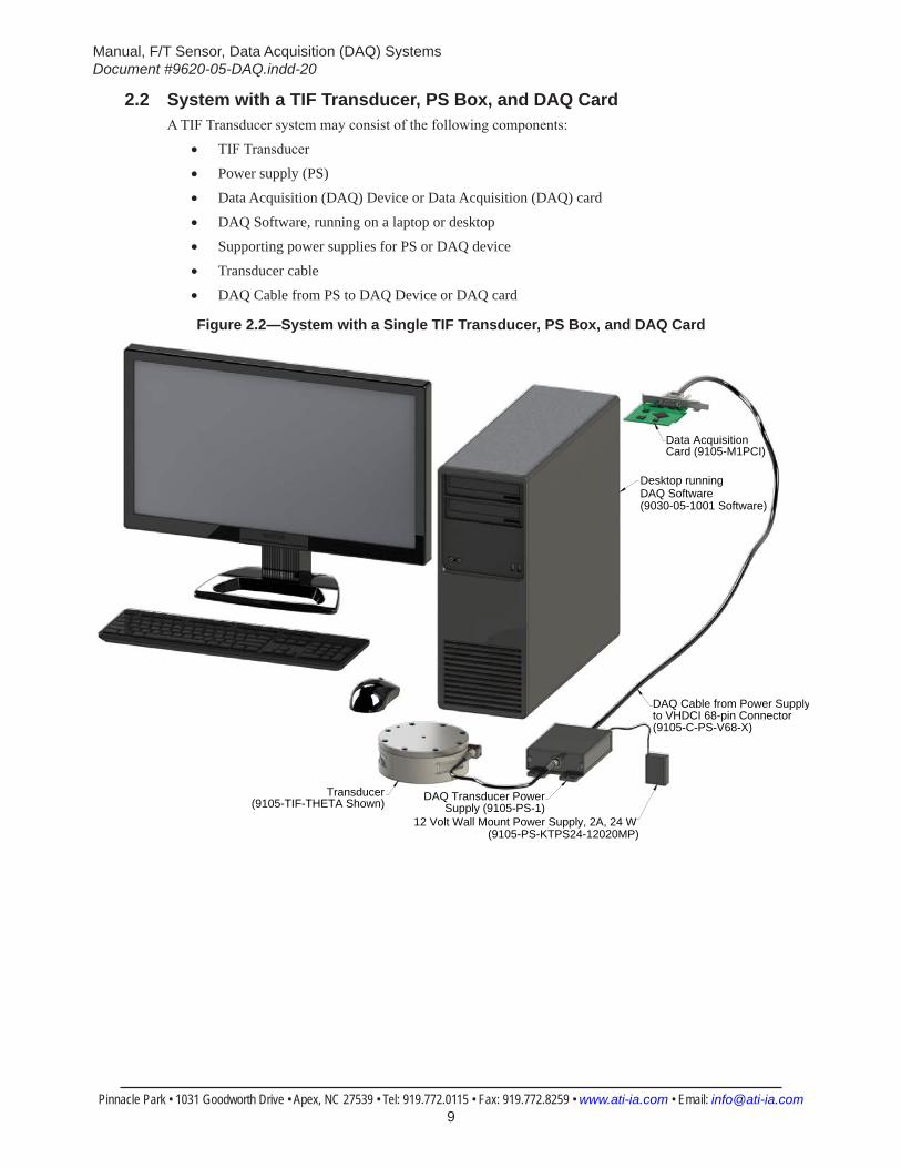
2.2 System with a TIF Transducer, PS Box, and DAQ CardA TIF Transducer system may consist of the following components:
• TIF Transducer
• Power supply (PS)
• Data Acquisition (DAQ) Device or Data Acquisition (DAQ) card
• DAQ Software, running on a laptop or desktop
• Supporting power supplies for PS or DAQ device
• Transducer cable
• DAQ Cable from PS to DAQ Device or DAQ card
Figure 2.2—System with a Single TIF Transducer, PS Box, and DAQ Card
Desktop runningDAQ Software
Data AcquisitionCard (9105-M1PCI)
Transducer(9105-TIF-THETA Shown) DAQ Transducer Power
Supply (9105-PS-1)
DAQ Cable from Power Supply to VHDCI 68-pin Connector(9105-C-PS-V68-X)
12 Volt Wall Mount Power Supply, 2A, 24 W (9105-PS-KTPS24-12020MP)
(9030-05-1001 Software)
Manual, F/T Sensor, Data Acquisition (DAQ) SystemsDocument #9620-05-DAQ.indd-20
Pinnacle Park • 1031 Goodworth Drive • Apex, NC 27539 • Tel: 919.772.0115 • Fax: 919.772.8259 • www.ati-ia.com • Email: [email protected] 10
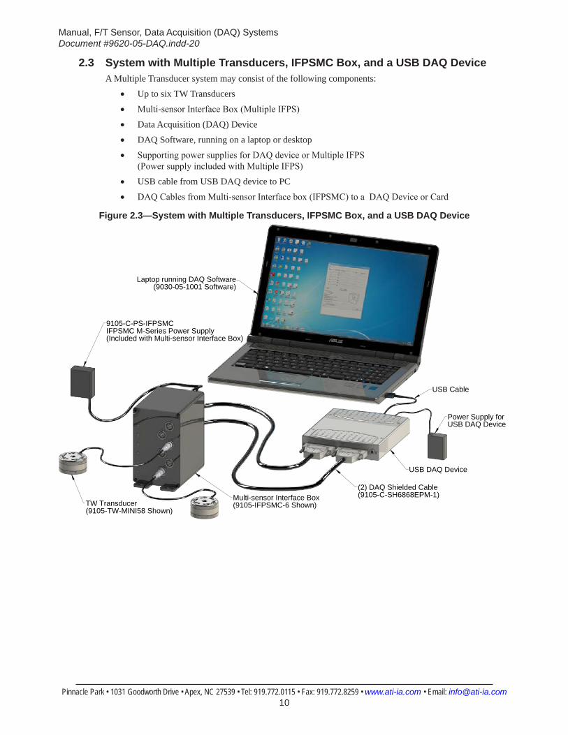
2.3 System with Multiple Transducers, IFPSMC Box, and a USB DAQ DeviceA Multiple Transducer system may consist of the following components:
• Up to six TW Transducers
• Multi-sensor Interface Box (Multiple IFPS)
• Data Acquisition (DAQ) Device
• DAQ Software, running on a laptop or desktop
• Supporting power supplies for DAQ device or Multiple IFPS (Power supply included with Multiple IFPS)
• USB cable from USB DAQ device to PC
• DAQ Cables from Multi-sensor Interface box (IFPSMC) to a DAQ Device or Card
Figure 2.3—System with Multiple Transducers, IFPSMC Box, and a USB DAQ Device
TW Transducer(9105-TW-MINI58 Shown)
USB DAQ Device
Power Supply for USB DAQ Device
USB Cable
Laptop running DAQ Software(9030-05-1001 Software)
Multi-sensor Interface Box(9105-IFPSMC-6 Shown)
(2) DAQ Shielded Cable(9105-C-SH6868EPM-1)
9105-C-PS-IFPSMC IFPSMC M-Series Power Supply(Included with Multi-sensor Interface Box)

Manual, F/T Sensor, Data Acquisition (DAQ) SystemsDocument #9620-05-DAQ.indd-20
Pinnacle Park • 1031 Goodworth Drive • Apex, NC 27539 • Tel: 919.772.0115 • Fax: 919.772.8259 • www.ati-ia.com • Email: [email protected] 11
2.4 System with Multiple Transducers, IFPSMC Box, and a DAQ CardA Multiple Transducer system may consist of the following components:
• Up to six TW Transducers
• Multi-sensor Interface Box (Multiple IFPS)
• Data Acquisition (DAQ) Card
• DAQ Software, running on a laptop or desktop
• Supporting power supplies for DAQ device or Multiple IFPS (Power supply included with Multiple IFPS)
• DAQ Cables from Multi-sensor Interface box (IFPSMC) to a DAQ Device or Card
Figure 2.4—System with Multiple Transducers, IFPSMC Box, and a DAQ Card
Desktop running DAQ Software(9030-05-1001 Software)
PCI DAQ Card(9105-M1PCI6225)
9105-C-PS-IFPSMC IFPSMC Power Supply
(Included with Multi-sensor Interface Box)
Multi-sensor Interface Box(9105-IFPSMC-6 Shown)
TW Transducer(9105-TW-MINI58 Shown)
(2) DAQ Shielded Cable(9105-C-SHC6868EPM-1)
Manual, F/T Sensor, Data Acquisition (DAQ) SystemsDocument #9620-05-DAQ.indd-20
Pinnacle Park • 1031 Goodworth Drive • Apex, NC 27539 • Tel: 919.772.0115 • Fax: 919.772.8259 • www.ati-ia.com • Email: [email protected] 12
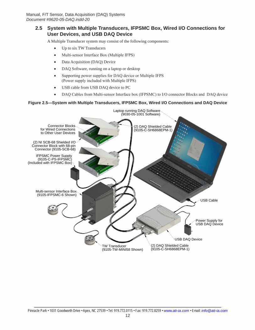
2.5 System with Multiple Transducers, IFPSMC Box, Wired I/O Connections for User Devices, and USB DAQ DeviceA Multiple Transducer system may consist of the following components:
• Up to six TW Transducers
• Multi-sensor Interface Box (Multiple IFPS)
• Data Acquisition (DAQ) Device
• DAQ Software, running on a laptop or desktop
• Supporting power supplies for DAQ device or Multiple IFPS (Power supply included with Multiple IFPS)
• USB cable from USB DAQ device to PC
• DAQ Cables from Multi-sensor Interface box (IFPSMC) to I/O connector Blocks and DAQ device
Figure 2.5—System with Multiple Transducers, IFPSMC Box, Wired I/O Connections and DAQ Device
USB Cable
Laptop running DAQ Software(9030-05-1001 Software)
TW Transducer(9105-TW-MINI58 Shown)
Multi-sensor Interface Box(9105-IFPSMC-6 Shown)
USB DAQ Device
(2) NI SCB-68 Shielded I/O Connector Block with 68-pin
Connector (9105-SCB-68)
Connector Blocks for Wired Connections to Other User Devices
IFPSMC Power Supply(9105-C-PS-IFPSMC)
(Included with IFPSMC Box)
(2) DAQ Shielded Cable (9105-C-SH6868EPM-1)
(2) DAQ Shielded Cable (9105-C-SH6868EPM-1)
Power Supply forUSB DAQ Device
Manual, F/T Sensor, Data Acquisition (DAQ) SystemsDocument #9620-05-DAQ.indd-20
Pinnacle Park • 1031 Goodworth Drive • Apex, NC 27539 • Tel: 919.772.0115 • Fax: 919.772.8259 • www.ati-ia.com • Email: [email protected] 13
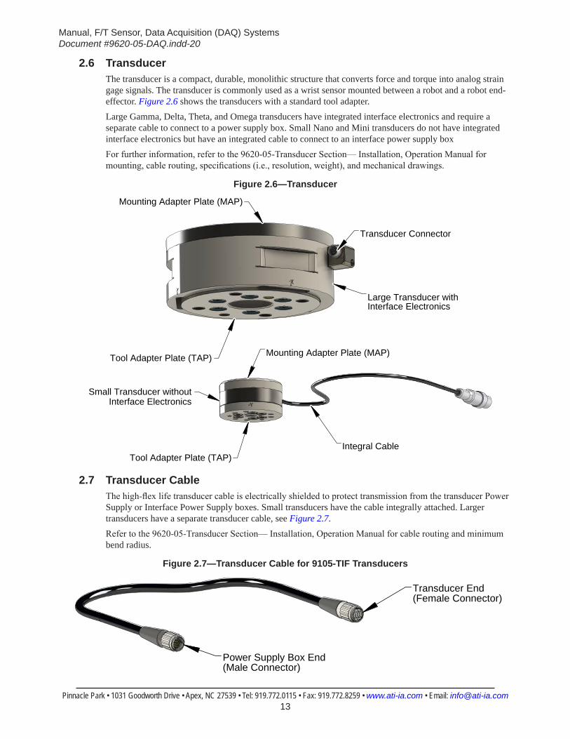
2.6 TransducerThe transducer is a compact, durable, monolithic structure that converts force and torque into analog strain gage signals. The transducer is commonly used as a wrist sensor mounted between a robot and a robot end-effector. Figure 2.6 shows the transducers with a standard tool adapter. Large Gamma, Delta, Theta, and Omega transducers have integrated interface electronics and require a separate cable to connect to a power supply box. Small Nano and Mini transducers do not have integrated interface electronics but have an integrated cable to connect to an interface power supply box For further information, refer to the 9620-05-Transducer Section— Installation, Operation Manual for mounting, cable routing, specifications (i.e., resolution, weight), and mechanical drawings.
Figure 2.6—Transducer
Transducer Connector
Mounting Adapter Plate (MAP)
Tool Adapter Plate (TAP)
Large Transducer with Interface Electronics
Tool Adapter Plate (TAP)
Mounting Adapter Plate (MAP)
Integral Cable
Small Transducer withoutInterface Electronics
2.7 Transducer CableThe high-flex life transducer cable is electrically shielded to protect transmission from the transducer Power Supply or Interface Power Supply boxes. Small transducers have the cable integrally attached. Larger transducers have a separate transducer cable, see Figure 2.7.Refer to the 9620-05-Transducer Section— Installation, Operation Manual for cable routing and minimum bend radius.
Figure 2.7—Transducer Cable for 9105-TIF Transducers
Transducer End (Female Connector)
Power Supply Box End(Male Connector)

Manual, F/T Sensor, Data Acquisition (DAQ) SystemsDocument #9620-05-DAQ.indd-20
Pinnacle Park • 1031 Goodworth Drive • Apex, NC 27539 • Tel: 919.772.0115 • Fax: 919.772.8259 • www.ati-ia.com • Email: [email protected] 14
2.8 Interface Power Supply BoxThe Interface Power Supply (IFPS) box is used with the small Nano and Mini transducers. The IFPS Box supplies power to the transducer and supplementary electronics; it also conditions the transducer signals utilized by the data acquisition system.Power to the IFPS box can be provided through either the 12 V wall-mounted power supply included with the IFPS box; or a 5 V source from the DAQ device through the 26-Pin male connector located on the box. The IFPS box only requires one source; if both sources are connected, the IFPS box will use the 12 V source and the 5 V source will be ignored.
Figure 2.8—Interface Power Supply
12-pin FemaleTransducer Connector
Interface Power Supply Box (9105-IFPS-1)
26-pin MaleDAQ Device Connector
12 V Wall Mount Power Supply, 2 A, 24 W (9105-PS-KTPS24-12020MP)
Manual, F/T Sensor, Data Acquisition (DAQ) SystemsDocument #9620-05-DAQ.indd-20
Pinnacle Park • 1031 Goodworth Drive • Apex, NC 27539 • Tel: 919.772.0115 • Fax: 919.772.8259 • www.ati-ia.com • Email: [email protected] 15
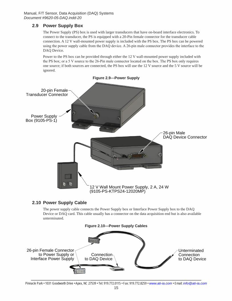
2.9 Power Supply BoxThe Power Supply (PS) box is used with larger transducers that have on-board interface electronics. To connect to the transducer, the PS is equipped with a 20-Pin female connector for the transducer cable connection. A 12 V wall-mounted power supply is included with the PS box. The PS box can be powered using the power supply cable from the DAQ device. A 26-pin male connector provides the interface to the DAQ Device.Power to the PS box can be provided through either the 12 V wall-mounted power supply included with the PS box; or a 5 V source to the 26-Pin male connector located on the box. The PS box only requires one source; if both sources are connected, the PS box will use the 12 V source and the 5 V source will be ignored.
Figure 2.9—Power Supply
20-pin FemaleTransducer Connector
Power Supply Box (9105-PS-1)
26-pin MaleDAQ Device Connector
12 V Wall Mount Power Supply, 2 A, 24 W (9105-PS-KTPS24-12020MP)
2.10 Power Supply CableThe power supply cable connects the Power Supply box or Interface Power Supply box to the DAQ Device or DAQ card. This cable usually has a connector on the data acquisition end but is also available unterminated.
Figure 2.10—Power Supply Cables
26-pin Female Connectorto Power Supply or
Interface Power SupplyConnection
to DAQ Device
Unterminated Connection to DAQ Device
Manual, F/T Sensor, Data Acquisition (DAQ) SystemsDocument #9620-05-DAQ.indd-20
Pinnacle Park • 1031 Goodworth Drive • Apex, NC 27539 • Tel: 919.772.0115 • Fax: 919.772.8259 • www.ati-ia.com • Email: [email protected] 16
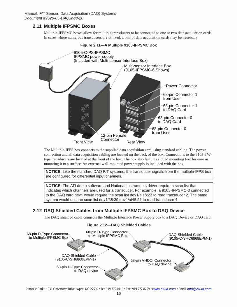
2.11 Multiple IFPSMC BoxesMultiple-IFPSMC boxes allow for multiple transducers to be connected to one or two data acquisition cards. In cases where numerous transducers are utilized, a pair of data acquisition cards may be necessary.
Figure 2.11—A Multiple 9105-IFPSMC Box
Multi-sensor Interface Box(9105-IFPSMC-6 Shown)
12-pin FemaleConnector
9105-C-PS-IFPSMC IFPSMC power supply(Included with Multi-sensor Interface Box)
68-pin Connector 0 from User
68-pin Connector 0 to DAQ Card
68-pin Connector 1 to DAQ Card
68-pin Connector 1 from User
Power Connector
Front View Rear View
The Multiple-IFPS box connects to the supplied data acquisition card using standard cabling. The power connection and all data acquisition cabling are located on the back of the box. Connections to the 9105-TW-type transducers are located at the front of the box. The box also features slotted mounting feet for ease in mounting it to a surface. An external wall-mounted power supply is included with the box.
NOTICE: Like the standard DAQ F/T systems, the transducer signals from the multiple-IFPS box are configured for differential input channels.
NOTICE: The ATI demo software and National Instruments driver require a scan list that indicates which channels are used for a transducer. For example, a 9105-IFPSMC-3 connected to the DAQ card dev1 would require the scan list dev1/ai18:23 to read transducer 2. The same system would use the scan list dev1/38:39,dev1/ai48:51 to read transducer 4.
2.12 DAQ Shielded Cables from Multiple IFPSMC Box to DAQ DeviceThe DAQ shielded cable connects the Multiple Interface Power Supply box to a DAQ Device or DAQ card.
Figure 2.12—DAQ Shielded Cables
68-pin D-Type Connectorto Multiple IFPSMC Box
68-pin D-Type Connectorto DAQ device
68-pin D-Type Connectorto Multiple IFPSMC Box
68-pin VHDCI Connectorto DAQ device
DAQ Shielded Cable(9105-C-SH6868EPM-1)
DAQ Shielded Cable(9105-C-SHC6868EPM-1)
Manual, F/T Sensor, Data Acquisition (DAQ) SystemsDocument #9620-05-DAQ.indd-20
Pinnacle Park • 1031 Goodworth Drive • Apex, NC 27539 • Tel: 919.772.0115 • Fax: 919.772.8259 • www.ati-ia.com • Email: [email protected] 17
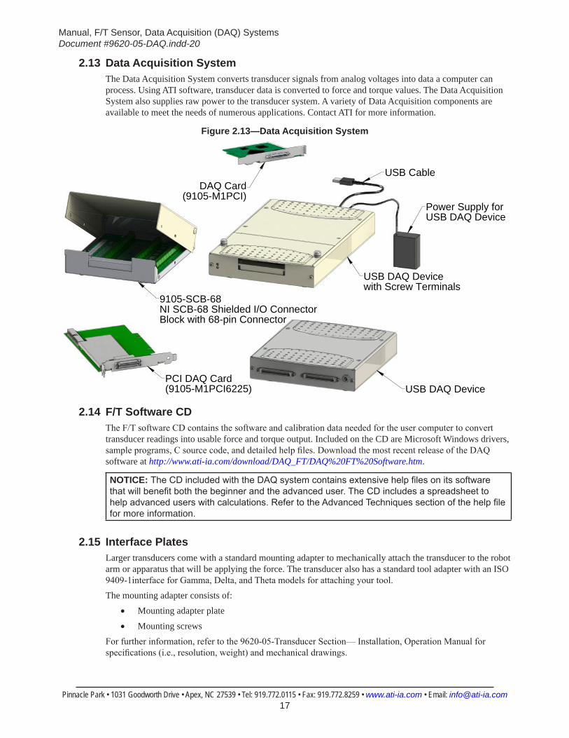
2.13 Data Acquisition SystemThe Data Acquisition System converts transducer signals from analog voltages into data a computer can process. Using ATI software, transducer data is converted to force and torque values. The Data Acquisition System also supplies raw power to the transducer system. A variety of Data Acquisition components are available to meet the needs of numerous applications. Contact ATI for more information.
Figure 2.13—Data Acquisition System
9105-SCB-68NI SCB-68 Shielded I/O ConnectorBlock with 68-pin Connector
Power Supply for USB DAQ Device
USB DAQ Device with Screw Terminals
USB CableDAQ Card
(9105-M1PCI)
USB DAQ Device PCI DAQ Card (9105-M1PCI6225)
2.14 F/T Software CDThe F/T software CD contains the software and calibration data needed for the user computer to convert transducer readings into usable force and torque output. Included on the CD are Microsoft Windows drivers, sample programs, C source code, and detailed help files. Download the most recent release of the DAQ software at http://www.ati-ia.com/download/DAQ_FT/DAQ%20FT%20Software.htm.
NOTICE: The CD included with the DAQ system contains extensive help files on its software that will benefit both the beginner and the advanced user. The CD includes a spreadsheet to help advanced users with calculations. Refer to the Advanced Techniques section of the help file for more information.
2.15 Interface PlatesLarger transducers come with a standard mounting adapter to mechanically attach the transducer to the robot arm or apparatus that will be applying the force. The transducer also has a standard tool adapter with an ISO 9409-1interface for Gamma, Delta, and Theta models for attaching your tool.The mounting adapter consists of:
• Mounting adapter plate
• Mounting screwsFor further information, refer to the 9620-05-Transducer Section— Installation, Operation Manual for specifications (i.e., resolution, weight) and mechanical drawings.
Manual, F/T Sensor, Data Acquisition (DAQ) SystemsDocument #9620-05-DAQ.indd-20
Pinnacle Park • 1031 Goodworth Drive • Apex, NC 27539 • Tel: 919.772.0115 • Fax: 919.772.8259 • www.ati-ia.com • Email: [email protected] 18
3. System FunctionalityThis section provides a functional outline of the F/T system. The F/T system is broken into four areas: Mechanical, Electrical, Load Calculations, and ATI DAQ Software.
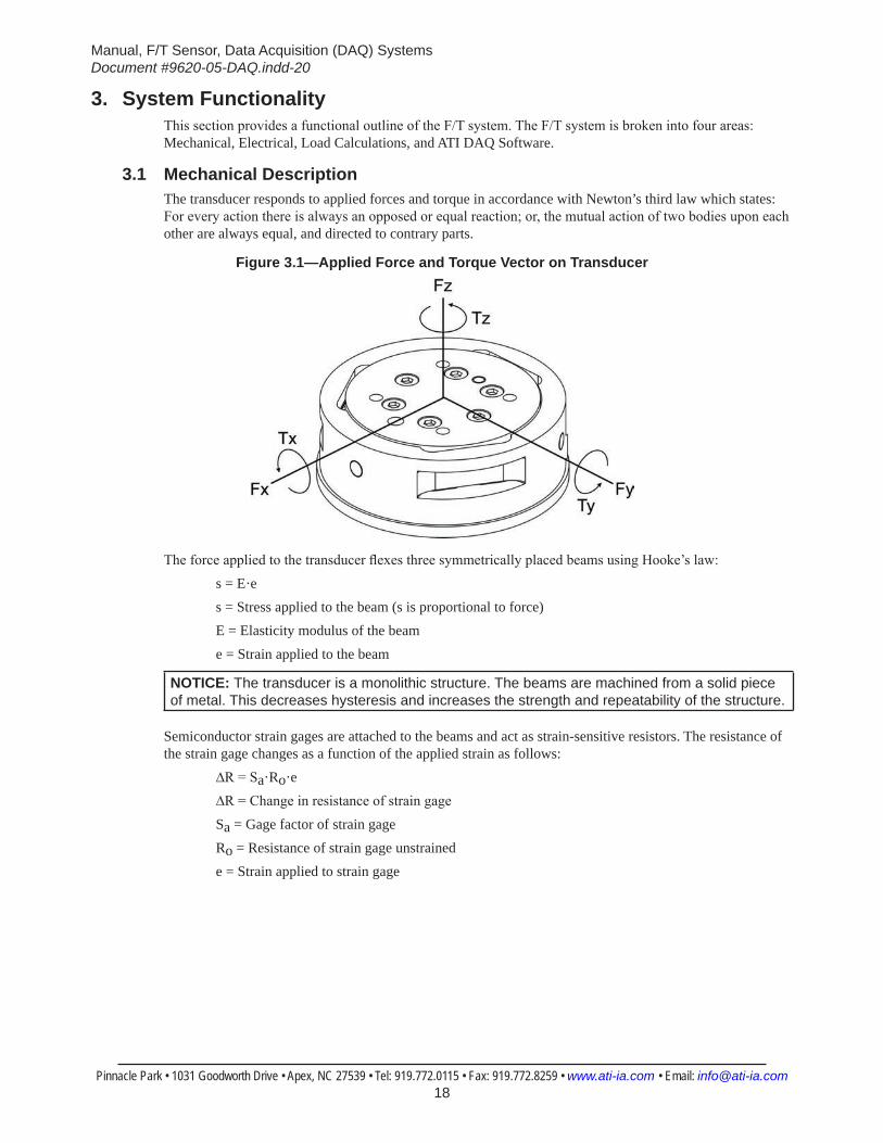
3.1 Mechanical DescriptionThe transducer responds to applied forces and torque in accordance with Newton’s third law which states: For every action there is always an opposed or equal reaction; or, the mutual action of two bodies upon each other are always equal, and directed to contrary parts.
Figure 3.1—Applied Force and Torque Vector on Transducer
The force applied to the transducer flexes three symmetrically placed beams using Hooke’s law: s = E·es = Stress applied to the beam (s is proportional to force)E = Elasticity modulus of the beam e = Strain applied to the beam
NOTICE: The transducer is a monolithic structure. The beams are machined from a solid piece of metal. This decreases hysteresis and increases the strength and repeatability of the structure.
Semiconductor strain gages are attached to the beams and act as strain-sensitive resistors. The resistance of the strain gage changes as a function of the applied strain as follows:
∆R = Sa·Ro·e∆R = Change in resistance of strain gageSa = Gage factor of strain gageRo = Resistance of strain gage unstrainede = Strain applied to strain gage

Manual, F/T Sensor, Data Acquisition (DAQ) SystemsDocument #9620-05-DAQ.indd-20
Pinnacle Park • 1031 Goodworth Drive • Apex, NC 27539 • Tel: 919.772.0115 • Fax: 919.772.8259 • www.ati-ia.com • Email: [email protected] 19
3.2 Electronic HardwareThe electronic hardware measures changes in resistance; the software described in Section 3.4—ATI DAQ Software, converts the changes to force and torque components.Figure 3.2 and Figure 3.3 depict an example of the electronic hardware used in a DAQ system. The figures also illustrate how the transducer’s voltage signal, created as a response to applied forces and torques are processed and routed to the DAQ card for conversion to usable force and torque data.
Figure 3.2—Electronic Hardware Outline Power supplied Through Data Acquisition Hardware
Data AcquisitionHardware
Transducer
Composite LoadingInformation (High-Level Voltages)
Composite Loading Information(Low-Level Voltages) Interface
Electronics
Power SupplyElectronicsPrecision
Power
RawPower
DigitalInformation
User's Computer
Data Acquisition card drivers receivetransducer load information.DAQ F/T software and transducercalibration data convert transducerload information into useable force and torque data.
Figure 3.3—Electronic Hardware Outline Power supplied by Separate Power Supply
Data AcquisitionHardware
Power Supply
Transducer
Composite LoadingInformation (High-Level Voltages)
Composite Loading Information(Low-Level Voltages) Interface
Electronics
Power SupplyElectronicsPrecision
Power
RawPower
DigitalInformation
User's Computer
Data Acquisition card drivers receivetransducer load information.DAQ F/T software and transducercalibration data convert transducerload information into useable force and torque data.
Manual, F/T Sensor, Data Acquisition (DAQ) SystemsDocument #9620-05-DAQ.indd-20
Pinnacle Park • 1031 Goodworth Drive • Apex, NC 27539 • Tel: 919.772.0115 • Fax: 919.772.8259 • www.ati-ia.com • Email: [email protected] 20
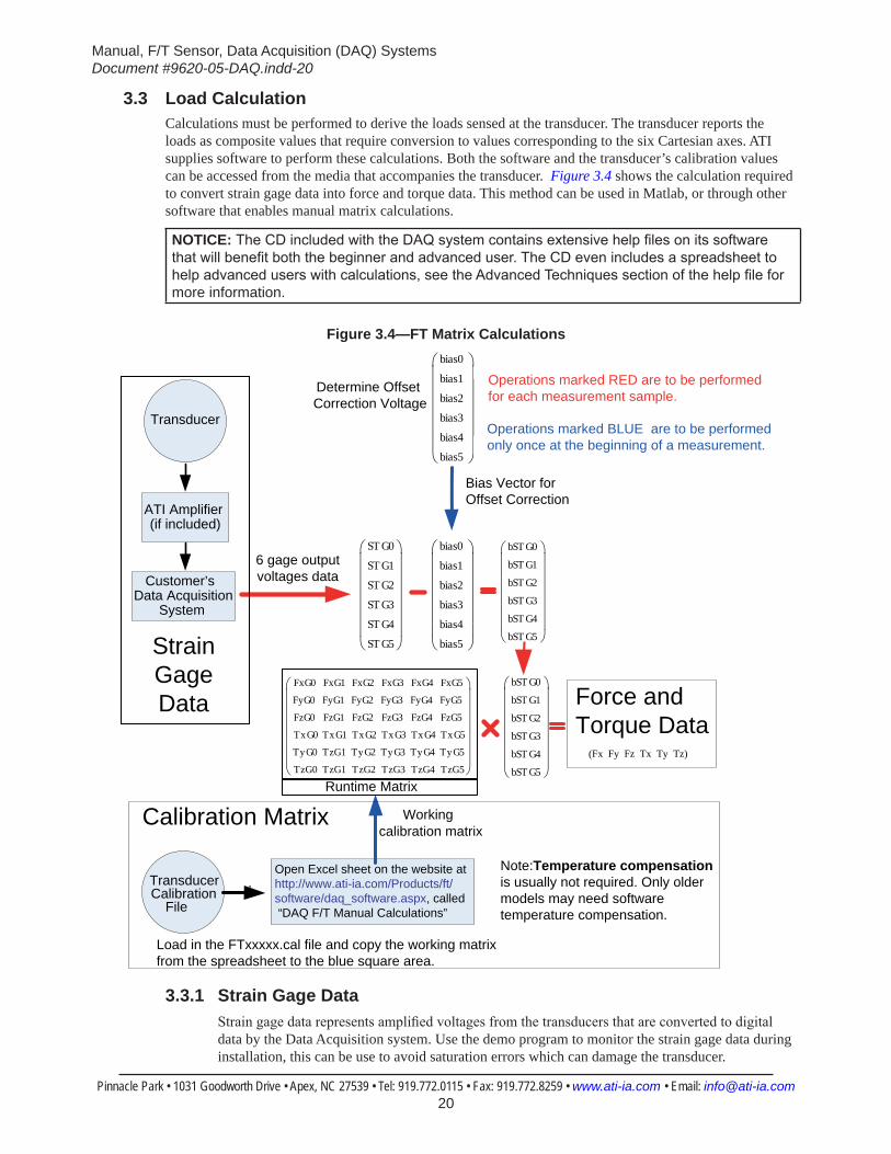
3.3 Load CalculationCalculations must be performed to derive the loads sensed at the transducer. The transducer reports the loads as composite values that require conversion to values corresponding to the six Cartesian axes. ATI supplies software to perform these calculations. Both the software and the transducer’s calibration values can be accessed from the media that accompanies the transducer. Figure 3.4 shows the calculation required to convert strain gage data into force and torque data. This method can be used in Matlab, or through other software that enables manual matrix calculations.
NOTICE: The CD included with the DAQ system contains extensive help files on its software that will benefit both the beginner and advanced user. The CD even includes a spreadsheet to help advanced users with calculations, see the Advanced Techniques section of the help file for more information.
Figure 3.4—FT Matrix Calculations
ST G0
ST G1
ST G2
ST G3
ST G4
ST G5
bias0
bias1
bias2
bias3
bias4
bias5
bST G0
bST G1
bST G2
bST G3
bST G4
bST G5
FxG0
FyG0
FzG0
TxG0
TyG0
TzG0
FxG1
FyG1
FzG1
TxG1
TzG1
TzG1
FxG2
FyG2
FzG2
TxG2
TyG2
TzG2
FxG3
FyG3
FzG3
TxG3
TyG3
TzG3
FxG4
FyG4
FzG4
TxG4
TyG4
TzG4
FxG5
FyG5
FzG5
TxG5
TyG5
TzG5
Runtime Matrix
Bias Vector for Offset Correction
Operations marked RED are to be performed for each measurement sample.
Operations marked BLUE are to be performed only once at the beginning of a measurement.
Transducer
ATI Amplifier (if included)
Customer’s Data Acquisition
System
6 gage outputvoltages data
Transducer Calibration
File
Open Excel sheet on the website at http://www.ati-ia.com/Products/ft/software/daq_software.aspx, called “DAQ F/T Manual Calculations”
Working calibration matrix
Determine Offset Correction Voltage
bias0
bias1
bias2
bias3
bias4
bias5
Note:Temperature compensation is usually not required. Only older models may need software temperature compensation.
Calibration Matrix
StrainGageData Force and
Torque Data(Fx Fy Fz Tx Ty Tz)
bST G0
bST G1
bST G2
bST G3
bST G4
bST G5
Load in the FTxxxxx.cal file and copy the working matrixfrom the spreadsheet to the blue square area.
3.3.1 Strain Gage DataStrain gage data represents amplified voltages from the transducers that are converted to digital data by the Data Acquisition system. Use the demo program to monitor the strain gage data during installation, this can be use to avoid saturation errors which can damage the transducer.
Manual, F/T Sensor, Data Acquisition (DAQ) SystemsDocument #9620-05-DAQ.indd-20
Pinnacle Park • 1031 Goodworth Drive • Apex, NC 27539 • Tel: 919.772.0115 • Fax: 919.772.8259 • www.ati-ia.com • Email: [email protected] 21
3.3.2 Offset CorrectionOffset correction is a bias vector that zeros out the force and torque data compensating for the weight of tooling or variation in room temperature. For an example without offset correction the tooling weight will be seen as a force data on the transducer, using offset correction the force from the weight of the tool will be zeroed out.
3.3.3 Calibration MatrixThe calibration matrix is the transducer calibration matrix provided on the CD from ATI. This standard matrix when, multiplied by the biased strain gage data being generated from the transducer, will provide the force and torque data that can be used for the application.
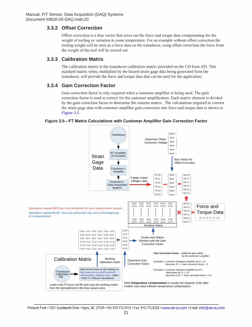
3.3.4 Gain Correction FactorGain correction factor is only required when a customer amplifier is being used. The gain correction factor is used to correct for the customer amplification. Each matrix element is divided by the gain correction factor to determine the runtime matrix. The calculations required to convert the strain gage data with customer amplifier gain correction into force and torque data is shown in Figure 3.5.
Figure 3.5—FTMatrixCalculationswithCustomerAmplifierGainCorrectionFactor
ST G0
ST G1
ST G2
ST G3
ST G4
ST G5
bias0
bias1
bias2
bias3
bias4
bias5
bST G0
bST G1
bST G2
bST G3
bST G4
bST G5
GCF0
GCF1
GCF2
GCF3
GCF4
GCF5
Runtime Matrix
FxG0
FyG0
FzG0
TxG0
TyG0
TzG0
FxG1
FyG1
FzG1
TxG1
TzG1
TzG1
FxG2
FyG2
FzG2
TxG2
TyG2
TzG2
FxG3
FyG3
FzG3
TxG3
TyG3
TzG3
FxG4
FyG4
FzG4
TxG4
TyG4
TzG4
FxG5
FyG5
FzG5
TxG5
TyG5
TzG5
Divide each Matrix Element with the Gain
Correction Factor
Bias Vector for Offset Correction
FxG0
TzG0
GCF0
GCF0
FxG1
TzG1
GCF1
GCF1
FxG2
TzG2
GCF2
GCF2
FxG3
TzG3
GCF3
GCF3
FxG4
TzG4
GCF4
GCF4
FxG5
TzG5
GCF5
GCF5
Determine Gain Correction Factor
Operations marked RED are to be performed for each measurement sample.Operations marked BLUE are to be performed only once at the beginning of a measurement.
Gain Correction Factor = additional gain added by the customer’s amplifier.
Example 1: customer hardware amplifies by 2-> 1V becomes 2V -> Gain correction factor = 2
Example 2: customer hardware amplifies by 0.5 (attenuates by 2) -> 1V becomes 0.5V -> Gain correction factor = 0.5
Transducer
ATI Amplifier (if included)
Customer’s Amplifier
Customer’s Data Acquisition
System
6 gage outputvoltages data
Transducer Calibration
File
Open Excel sheet on the website at http://www.ati-ia.com/Products/ft/software/daq_software.aspx, called “DAQ F/T Manual Calculations”
Workingcalibration matrix
Determine Offset Correction Voltage
bias0
bias1
bias2
bias3
bias4
bias5
Note:Temperature compensation is usually not required. Only older models may need software temperature compensation.
Calibration Matrix
StrainGageData
Force andTorque Data
(Fx Fy Fz Tx Ty Tz)
bST G0
bST G1
bST G2
bST G3
bST G4
bST G5
Load in the FTxxxxx.cal file and copy the working matrix from the spreadsheet to the blue square area.
Manual, F/T Sensor, Data Acquisition (DAQ) SystemsDocument #9620-05-DAQ.indd-20
Pinnacle Park • 1031 Goodworth Drive • Apex, NC 27539 • Tel: 919.772.0115 • Fax: 919.772.8259 • www.ati-ia.com • Email: [email protected] 22
3.4 ATI DAQ SoftwareThe computer with the F/T system’s data acquisition card installed or data acquisition device attached, converts the strain gage data into useful force and torque values. The ATI DAQ software provides a user interface for viewing and editing (or providing controls) the data values.The ATI DAQ F/T Software files contain reusable software components that you can use to build your application, as well as sample applications to get you started. (Unless otherwise noted, all Windows components and applications support Windows XP, Vista, 2007, and 2008).
NOTICE: The ATI DAQ F/T software files contain extensive documentation on its software. Check this documentation for detailed help. File updates can be found at: http://www.ati-ia.com/download/DAQ_FT/DAQ%20FT%20Software.htm.
3.4.1 Reusable Software Components
3.4.1.1 ATI DAQ FT Automation ServerThis Windows ActiveX component reads calibration files, configures the transducer system, and converts raw voltages from any data acquisition system into forces and torques. ATIDAQFT can be used in development platforms that support ActiveX or Automation containment, including Microsoft Visual Basic 6.0, Microsoft Visual C++, Microsoft.NET Platform, National Instruments LabVIEW, and many others. Its programming API is documented in the ATIDAQFT help files.
3.4.1.2 C LibraryThis code library uses standard ANSI C to read calibration files, configure the transducer system, and convert voltage data from any data acquisition system into forces and torques.
3.4.2 Sample Applications
3.4.2.1 Windows Demo (Visual Basic 6.0)This executable program is a good place to try out your new transducer system in Windows. It uses National Instruments software and ATIDAQFT to give a real-time display of F/T data from National Instruments devices. It provides complete options for configuration of the F/T system. Microsoft Visual Basic 6.0 source is included. With the IFPSMC system, only one transducer can be viewed at a time with the correct scan list used.
3.4.2.2 LabVIEW SampleThis is a demo application in LabVIEW using the ATIDAQFT Automation server and the Analog Input VIs provided by NI-DAQ. This sample application provides a real-time display of F/T data.
Manual, F/T Sensor, Data Acquisition (DAQ) SystemsDocument #9620-05-DAQ.indd-20
Pinnacle Park • 1031 Goodworth Drive • Apex, NC 27539 • Tel: 919.772.0115 • Fax: 919.772.8259 • www.ati-ia.com • Email: [email protected] 23
3.4.3 Designing Your DAQ F/T ApplicationYour DAQ F/T application must include at least two components:
3.4.3.1 Device Drivers for Your DAQ Device and Target Operating SystemNational Instruments includes several sets of Windows device drivers with their data acquisition devices, including 32-bit DLLs, LabVIEW VIs, and ActiveX controls. Non-Windows device drivers for National Instruments systems may be available from third-party sources. For other brands of data acquisition devices, device drivers must be obtained from the device manufacturer or a third-party source.
3.4.3.2 ATI DAQ F/T Components or C LibraryThis part of your application is used to load a calibration file, apply settings such as tool transformations, and convert raw voltages into forces and torques. For Windows applications, the ATI DAQ FT Automation server is recommended. The conversion to forces and torques can occur in real time, or can be applied as a batch operation at the end of the acquisition operation.
In some applications, using the ATI DAQ FT component to process data is impractical. This could be due to client applications or operating systems that do not support ActiveX, or very high-speed real-time performance requirements. In these cases, ATI DAQ FT can be used during configuration stages but need not be present in the final application. For more information, see the ATI DAQ FT Component Reference/Designing Your Application/ Advanced Techniques section of the ATI DAQ FT help file.
Manual, F/T Sensor, Data Acquisition (DAQ) SystemsDocument #9620-05-DAQ.indd-20
Pinnacle Park • 1031 Goodworth Drive • Apex, NC 27539 • Tel: 919.772.0115 • Fax: 919.772.8259 • www.ati-ia.com • Email: [email protected] 24
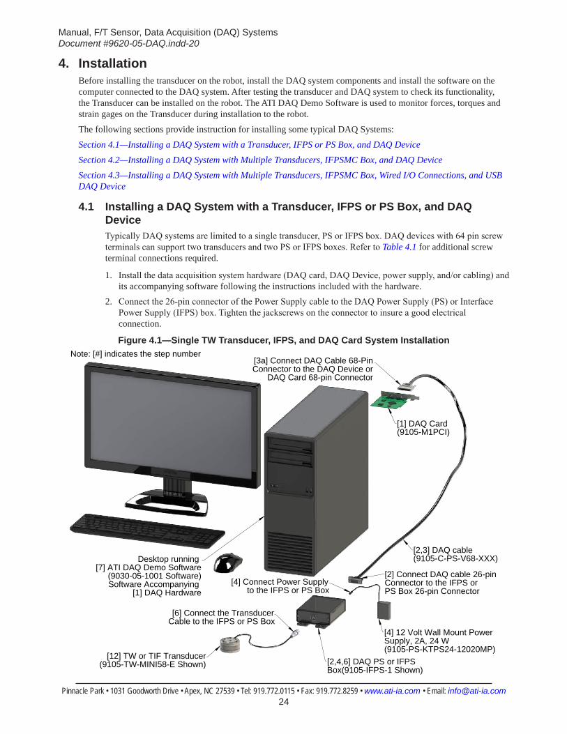
4. InstallationBefore installing the transducer on the robot, install the DAQ system components and install the software on the computer connected to the DAQ system. After testing the transducer and DAQ system to check its functionality, the Transducer can be installed on the robot. The ATI DAQ Demo Software is used to monitor forces, torques and strain gages on the Transducer during installation to the robot.
The following sections provide instruction for installing some typical DAQ Systems:
Section 4.1—Installing a DAQ System with a Transducer, IFPS or PS Box, and DAQ DeviceSection 4.2—Installing a DAQ System with Multiple Transducers, IFPSMC Box, and DAQ DeviceSection 4.3—Installing a DAQ System with Multiple Transducers, IFPSMC Box, Wired I/O Connections, and USB DAQ Device
4.1 Installing a DAQ System with a Transducer, IFPS or PS Box, and DAQ DeviceTypically DAQ systems are limited to a single transducer, PS or IFPS box. DAQ devices with 64 pin screw terminals can support two transducers and two PS or IFPS boxes. Refer to Table 4.1 for additional screw terminal connections required.
1. Install the data acquisition system hardware (DAQ card, DAQ Device, power supply, and/or cabling) and its accompanying software following the instructions included with the hardware.
2. Connect the 26-pin connector of the Power Supply cable to the DAQ Power Supply (PS) or Interface Power Supply (IFPS) box. Tighten the jackscrews on the connector to insure a good electrical connection.
Figure 4.1—Single TW Transducer, IFPS, and DAQ Card System Installation
Desktop running [7] ATI DAQ Demo Software
(9030-05-1001 Software)Software Accompanying
[1] DAQ Hardware
[1] DAQ Card(9105-M1PCI)
[12] TW or TIF Transducer(9105-TW-MINI58-E Shown)
[2,3] DAQ cable (9105-C-PS-V68-XXX)
[4] 12 Volt Wall Mount Power Supply, 2A, 24 W (9105-PS-KTPS24-12020MP)
[6] Connect the Transducer Cable to the IFPS or PS Box
[4] Connect Power Supply to the IFPS or PS Box
[2] Connect DAQ cable 26-pin Connector to the IFPS or PS Box 26-pin Connector
[3a] Connect DAQ Cable 68-Pin Connector to the DAQ Device or
DAQ Card 68-pin Connector
[2,4,6] DAQ PS or IFPS Box(9105-IFPS-1 Shown)
Note: [#] indicates the step number
Manual, F/T Sensor, Data Acquisition (DAQ) SystemsDocument #9620-05-DAQ.indd-20
Pinnacle Park • 1031 Goodworth Drive • Apex, NC 27539 • Tel: 919.772.0115 • Fax: 919.772.8259 • www.ati-ia.com • Email: [email protected] 25
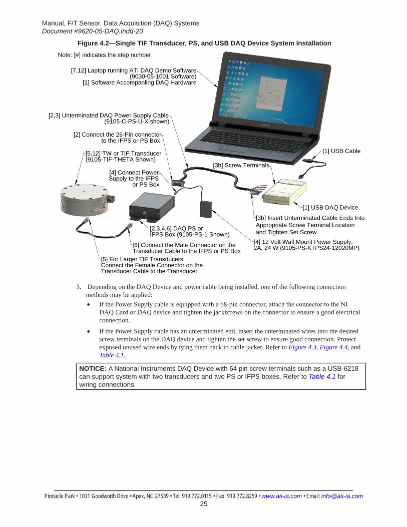
Figure 4.2—Single TIF Transducer, PS, and USB DAQ Device System Installation
[7,12] Laptop running ATI DAQ Demo Software(9030-05-1001 Software)
[1] Software Accompanling DAQ Hardware
[2] Connect the 26-Pin connector to the IFPS or PS Box
[4] Connect Power Supply to the IFPS
or PS Box
[5,12] TW or TIF Transducer(9105-TIF-THETA Shown)
[5] For Larger TIF Transducers Connect the Female Connector on the Transducer Cable to the Transducer
[2,3,4,6] DAQ PS or IFPS Box (9105-PS-1 Shown)
[6] Connect the Male Connector on the Transducer Cable to the IFPS or PS Box
[4] 12 Volt Wall Mount Power Supply, 2A, 24 W (9105-PS-KTPS24-12020MP)
[3b] Insert Unterminated Cable Ends IntoAppropriate Screw Terminal Locationand Tighten Set Screw
[3b] Screw Terminals
[1] USB Cable
[1] USB DAQ Device
[2,3] Unterminated DAQ Power Supply Cable(9105-C-PS-U-X shown)
Note: [#] indicates the step number
3. Depending on the DAQ Device and power cable being installed, one of the following connection methods may be applied:• If the Power Supply cable is equipped with a 68-pin connector, attach the connector to the NI
DAQ Card or DAQ device and tighten the jackscrews on the connector to ensure a good electrical connection.
• If the Power Supply cable has an unterminated end, insert the unterminated wires into the desired screw terminals on the DAQ device and tighten the set screw to ensure good connection. Protect exposed unused wire ends by tying them back to cable jacket. Refer to Figure 4.3, Figure 4.4, and Table 4.1.
NOTICE: A National Instruments DAQ Device with 64 pin screw terminals such as a USB-6218 can support system with two transducers and two PS or IFPS boxes. Refer to Table 4.1 for wiring connections.

Manual, F/T Sensor, Data Acquisition (DAQ) SystemsDocument #9620-05-DAQ.indd-20
Pinnacle Park • 1031 Goodworth Drive • Apex, NC 27539 • Tel: 919.772.0115 • Fax: 919.772.8259 • www.ati-ia.com • Email: [email protected] 26
Figure 4.3—Unterminated Cable Wiring (9105-C-PS-U-x) and USB DAQ Device System Installation
USB DAQ Device [1]
[3b] Insert unterminated Cable Ends Into Appropriate Screw Terminal Location and Tighten Set Screw
[2,3,4,6] DAQ PS or IFPS Box (9105-PS-1 Shown)
[4] 12 Volt Wall Mount Power Supply, 2A,24 W (9105-PS-KTPS24-12020MP)
[3b] Protect Exposed Unused Wire Ends and Tie Wires Back to Cable Jacket
[3b] Twist Shielding Together and Insert Into DGND
[3b] If 12 Volt Wall Mount Power Supply is Being Used, do not Connect the
Red Wire to DGND or theRed/White Wire to +5V
Protect Wire Ends and Tie Wires Back to Cable Jacket
[1] USB Cable
Note: [#] Indicates the Step Number.
NOTICE: If you are not using a National Instruments DAQ board with mass termination, you must provide your own connector at that end of the cable. See Section 4.5—Electrical Connection Information for connection information.
Figure 4.4—Unterminated Cable Wiring (9105-C-PS-U-x) for a NI 32 Screw Terminal USB DAQ Device
(SG1 Output) Yellow to AI1
Protect Unused Wire Endsand Tie Back to Cable Jacket
Twisted Shielding to DGND
(SG0 Output) Brown to AI0(SG0 Ref) Brown/White to AI8
(SG1 Ref) Yellow/White to AI9Green/White to AI10 (SG2 Ref)(SG2 Output) Green to AI2
Blue to AI3 (SG3 Output)Blue/White to AI11 (SG3 Ref)
Violet to AI4 (SG4 Output)Violet/White to AI12 (SG4 Ref)
Grey to AI5 (SG5 Output)Grey/White to AI13 (SG5 Ref)
Black to AIGND (AIGnd)

Manual, F/T Sensor, Data Acquisition (DAQ) SystemsDocument #9620-05-DAQ.indd-20
Pinnacle Park • 1031 Goodworth Drive • Apex, NC 27539 • Tel: 919.772.0115 • Fax: 919.772.8259 • www.ati-ia.com • Email: [email protected] 27
Table 4.1—Unterminated Cable (9105-C-PS-U-x) for a NI 32 and 64 Pin Screw Terminal DAQ DeviceNI 32 or 64
Pin # and Screw Terminal Labels
Description Wire ColorsNI 64 Pin # and Screw Terminal
LabelsDescription Wire Colors
1 PFI 0/P0.0 (In) No ATI Connection N/A 33 PFI 8/P0.4 (In) No ATI Connection N/A
2 PFI 1/P0.1 (In) No ATI Connection N/A 34 PFI 9/P0.5 (In) No ATI Connection N/A
3 PFI 2/P0.2 (In) No ATI Connection N/A 35 PFI 10/P0.6 (In) No ATI Connection N/A
4 PFI 3/P0.3 (In) No ATI Connection N/A 36 PFI 11/P0.7 (In) No ATI Connection N/A
5 D GND No ATI Connection1 N/A1 37 D GND No ATI Connection1 N/A1
6 PFI 4/P1.0 (Out) No ATI Connection N/A 38 PFI 12/P1.4 (Out) No ATI Connection N/A
7 PFI 5/P1.1 (Out) No ATI Connection N/A 39 PFI 13/P1.5 (Out) No ATI Connection N/A
8 PFI 6/P1.2 (Out) No ATI Connection N/A 40 PFI 14/P1.6 (Out) No ATI Connection N/A
9 PFI 7/P1.3 (Out) No ATI Connection N/A 41 PFI 15/P1.7 (Out) No ATI Connection N/A
10 +5V No ATI Connection1 N/A1 42 +5V No ATI Connection1 N/A1
11 D GND Shielding Twisted shielding 43 D GND Shielding2 Twisted shielding2
12 NC or AO 0 No ATI Connection N/A 44 NC No ATI Connection N/A
13 NC or AO 1 No ATI Connection N/A 45 NC No ATI Connection N/A
14 Reser or AO GND No ATI Connection N/A 46 AI GND No ATI Connection N/A
15 AI 0 SG0 output Brown 47 AI 16 SG0 output2 Brown2
16 AI 8 SG0 reference Brown/White 48 AI 24 SG0 reference2 Brown/White2
17 AI 1 SG1 output Yellow 49 AI 17 SG1 output2 Yellow2
18 AI 9 SG1 reference Yellow/White 50 AI 25 SG1 reference2 Yellow/White2
19 AI 2 SG2 output Green 51 AI 18 SG2 output2 Green2
20 AI 10 SG2 reference Green/White 52 AI 26 SG2 reference2 Green/White2
21 AI 3 SG3 output Blue 53 AI 19 SG3 output2 Blue2
22 AI 11 SG3 reference Blue/White 54 AI 27 SG3 reference2 Blue/White2
23 AI SENSE No ATI Connection N/A 55 AI GND No ATI Connection N/A
24 AI 4 SG4 output Violet 56 AI 20 SG4 output2 Violet2
25 AI 12 SG4 reference Violet/White 57 AI 28 SG4 reference2 Violet/White2
26 AI 5 SG5 output Grey 58 AI 21 SG5 output2 Grey2
27 AI 13 SG5 reference Grey/White 59 AI 29 SG5 reference2 Grey/White2
28 AI GND AGnd power input Black 60 AI GND AI GND2 Black2
29 AI 6 No ATI Connection N/A 61 AI 22 No ATI Connection N/A
30 AI 14 No ATI Connection N/A 62 AI 30 No ATI Connection N/A
31 AI 7 No ATI Connection N/A 63 AI 23 No ATI Connection N/A
32 AI 15 No ATI Connection N/A 64 AI 31 No ATI Connection N/A
Notes: (Note # shown in table as superscript)1. Do not connect the (+5V) red wire and the power ground (DGND) red/white wire on systems that have PS or
IFPS boxes with a 12 V wall mounted power supply. The (+5V) red wire and the power ground (DGND) red/white wire are only required for systems that do not have a separate wall mounted power supply. Connect to external power source, not the +5V through the USB.
2. Indicates the wired connection for the 2nd transducer and PS or IFPS box for NI 64 Pin screw terminal connections only.

Manual, F/T Sensor, Data Acquisition (DAQ) SystemsDocument #9620-05-DAQ.indd-20
Pinnacle Park • 1031 Goodworth Drive • Apex, NC 27539 • Tel: 919.772.0115 • Fax: 919.772.8259 • www.ati-ia.com • Email: [email protected] 28
4. If equipped, plug 12 volt wall mount power supply into outlet and connect the power supply cable to the PS or IFPS box.
5. For larger TIF transducers, connect the female connector on the transducer cable to the transducer. a. Line up the groove on the connector to the key in the port by rotating the connector while lightly
forcing the connector into the port. When the groove lines up, the connector will noticeably go deeper into the port.
b. Screw the connector shell into the transducer until it seats firmly.
CAUTION: Cables on the Nano and Mini transducers are permanently attached to the transducer and cannot be disconnected. Do not attempt to disassemble these transducers as damage will occur.
Figure 4.5—Transducer Connector
Female Connector
Male Connector
GrooveGroove
12V Wall Mount Power Supply
PS or IFPS Box Power Supply Connector
TIF Transducer
6. Connect the male connector on the transducer cable to the connector on the PS or IFPS box.7. Refer to Section 4.4—Install the F/T Demo Software to complete the installation.
Manual, F/T Sensor, Data Acquisition (DAQ) SystemsDocument #9620-05-DAQ.indd-20
Pinnacle Park • 1031 Goodworth Drive • Apex, NC 27539 • Tel: 919.772.0115 • Fax: 919.772.8259 • www.ati-ia.com • Email: [email protected] 29
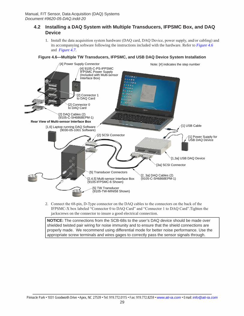
4.2 Installing a DAQ System with Multiple Transducers, IFPSMC Box, and DAQ Device1. Install the data acquisition system hardware (DAQ card, DAQ Device, power supply, and/or cabling) and
its accompanying software following the instructions included with the hardware. Refer to Figure 4.6 and Figure 4.7.
Figure 4.6—Multiple TW Transducers, IFPSMC, and USB DAQ Device System Installation
[5] TW Transducer(9105-TW-MINI58 Shown)
[1,3a] USB DAQ Device
[1] Power Supply for USB DAQ Device
[1] USB Cable[1,6] Laptop running DAQ Software(9030-05-1001 Software)
[2,4,5] Multi-sensor Interface Box(9105-IFPSMC-6 Shown)
[2, 3a] DAQ Cables (2)(9105-C-SH6868EPM-1)
[5] Transducer Connectors
[3a] SCSI Connector
[2] SCSI Connector
Note: [#] indicates the step number[4] Power Supply Connector[4] 9105-C-PS-IFPSMC IFPSMC Power Supply (Included with Multi-sensorInterface Box)
[2] Connector 1 to DAQ Card
[2] Connector 0 to DAQ Card
[2] DAQ Cables (2)(9105-C-SH6868EPM-1)
Rear View of Multi-sensor Interface Box
2. Connect the 68-pin, D-Type connector on the DAQ cables to the connectors on the back of the IFPSMC-X box labeled “Connector 0 to DAQ Card” and “Connector 1 to DAQ Card”.Tighten the jackscrews on the connector to insure a good electrical connection.
NOTICE: The connections from the SCB-68s to the user’s DAQ device should be made over shielded twisted pair wiring for noise immunity and to ensure that the shield connections are properly made. We recommend using differential mode for better noise performance. Use the appropriate screw terminals and wires gages to correctly pass the sensor signals through.
Manual, F/T Sensor, Data Acquisition (DAQ) SystemsDocument #9620-05-DAQ.indd-20
Pinnacle Park • 1031 Goodworth Drive • Apex, NC 27539 • Tel: 919.772.0115 • Fax: 919.772.8259 • www.ati-ia.com • Email: [email protected] 30
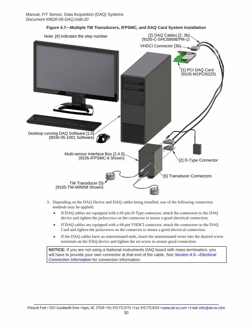
Figure 4.7—Multiple TW Transducers, IFPSMC, and DAQ Card System Installation
Desktop running DAQ Software [1,6](9030-05-1001 Software)
[1] PCI DAQ Card(9105-M1PCI6225)
Multi-sensor Interface Box [2,4,5](9105-IFPSMC-6 Shown)
TW Transducer [5](9105-TW-MINI58 Shown)
(2) DAQ Cables [2, 3b](9105-C-SHC6868EPM-1)
[5] Transducer Connectors
VHDCI Connector [3b]
[2] D-Type Connector
Note: [#] indicates the step number
3. Depending on the DAQ Device and DAQ cables being installed, one of the following connection methods may be applied:• If DAQ cables are equipped with a 68-pin D-Type connector, attach the connectors to the DAQ
device and tighten the jackscrews on the connector to insure a good electrical connection.
• If DAQ cables are equipped with a 68-pin VHDCI connector, attach the connectors to the DAQ Card and tighten the jackscrews on the connector to insure a good electrical connection.
• If the DAQ cables have an unterminated ends, insert the unterminated wires into the desired screw terminals on the DAQ device and tighten the set screw to ensure good connection.
NOTICE: If you are not using a National Instruments DAQ board with mass termination, you will have to provide your own connector at that end of the cable. See Section 4.5—Electrical Connection Information for connection information.
Manual, F/T Sensor, Data Acquisition (DAQ) SystemsDocument #9620-05-DAQ.indd-20
Pinnacle Park • 1031 Goodworth Drive • Apex, NC 27539 • Tel: 919.772.0115 • Fax: 919.772.8259 • www.ati-ia.com • Email: [email protected] 31
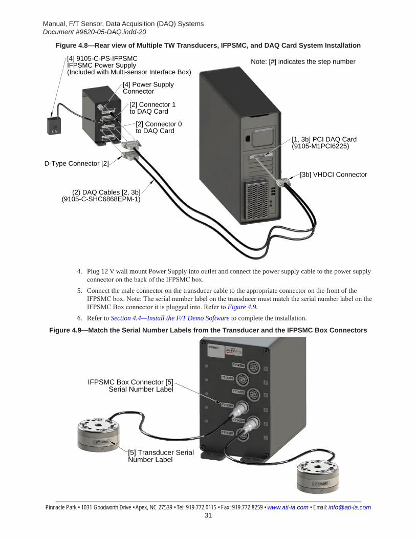
Figure 4.8—Rear view of Multiple TW Transducers, IFPSMC, and DAQ Card System Installation
[4] Power Supply Connector
[2] Connector 1 to DAQ Card
[2] Connector 0 to DAQ Card
(2) DAQ Cables [2, 3b](9105-C-SHC6868EPM-1)
[4] 9105-C-PS-IFPSMC IFPSMC Power Supply(Included with Multi-sensor Interface Box)
[1, 3b] PCI DAQ Card(9105-M1PCI6225)
D-Type Connector [2][3b] VHDCI Connector
Note: [#] indicates the step number
4. Plug 12 V wall mount Power Supply into outlet and connect the power supply cable to the power supply connector on the back of the IFPSMC box.
5. Connect the male connector on the transducer cable to the appropriate connector on the front of the IFPSMC box. Note: The serial number label on the transducer must match the serial number label on the IFPSMC Box connector it is plugged into. Refer to Figure 4.9.
6. Refer to Section 4.4—Install the F/T Demo Software to complete the installation.
Figure 4.9—Match the Serial Number Labels from the Transducer and the IFPSMC Box Connectors
[5] Transducer Serial Number Label
IFPSMC Box Connector [5] Serial Number Label
Manual, F/T Sensor, Data Acquisition (DAQ) SystemsDocument #9620-05-DAQ.indd-20
Pinnacle Park • 1031 Goodworth Drive • Apex, NC 27539 • Tel: 919.772.0115 • Fax: 919.772.8259 • www.ati-ia.com • Email: [email protected] 32
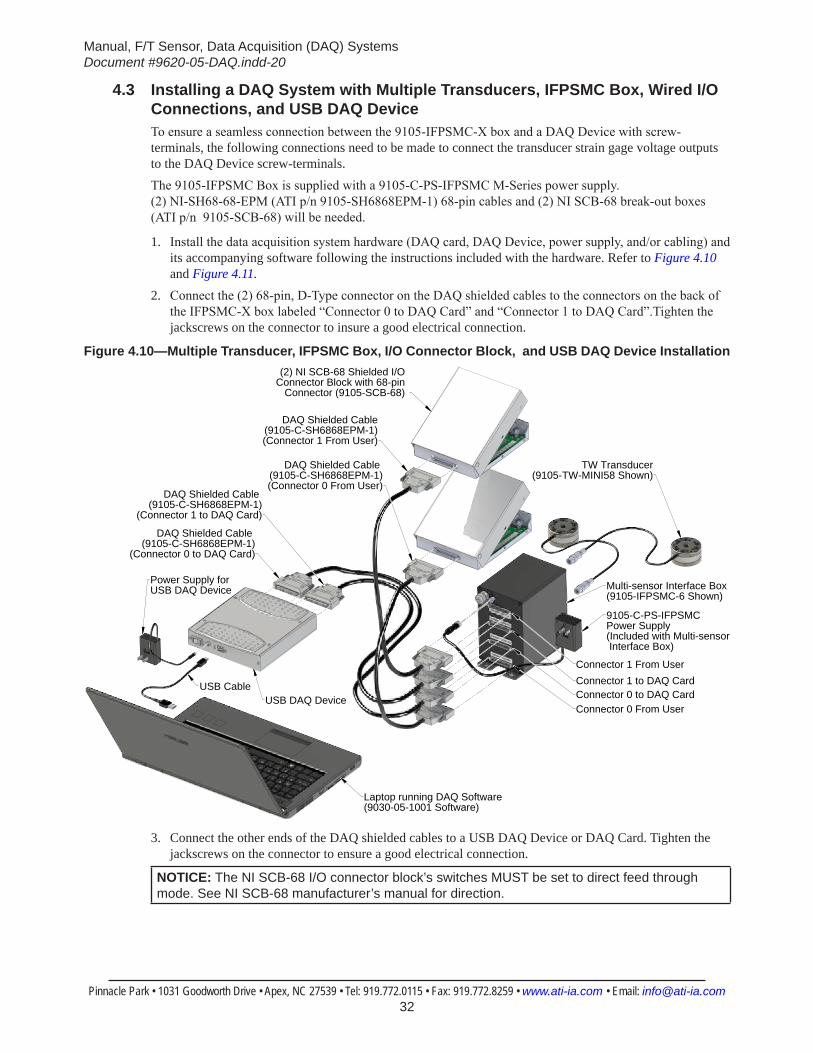
4.3 Installing a DAQ System with Multiple Transducers, IFPSMC Box, Wired I/O Connections, and USB DAQ DeviceTo ensure a seamless connection between the 9105-IFPSMC-X box and a DAQ Device with screw-terminals, the following connections need to be made to connect the transducer strain gage voltage outputs to the DAQ Device screw-terminals.The 9105-IFPSMC Box is supplied with a 9105-C-PS-IFPSMC M-Series power supply. (2) NI-SH68-68-EPM (ATI p/n 9105-SH6868EPM-1) 68-pin cables and (2) NI SCB-68 break-out boxes (ATI p/n 9105-SCB-68) will be needed.
1. Install the data acquisition system hardware (DAQ card, DAQ Device, power supply, and/or cabling) and its accompanying software following the instructions included with the hardware. Refer to Figure 4.10 and Figure 4.11.
2. Connect the (2) 68-pin, D-Type connector on the DAQ shielded cables to the connectors on the back of the IFPSMC-X box labeled “Connector 0 to DAQ Card” and “Connector 1 to DAQ Card”.Tighten the jackscrews on the connector to insure a good electrical connection.
Figure 4.10—Multiple Transducer, IFPSMC Box, I/O Connector Block, and USB DAQ Device Installation
Laptop running DAQ Software(9030-05-1001 Software)
USB CableUSB DAQ Device
DAQ Shielded Cable(9105-C-SH6868EPM-1)(Connector 1 From User)
Multi-sensor Interface Box(9105-IFPSMC-6 Shown)
9105-C-PS-IFPSMC Power Supply (Included with Multi-sensor Interface Box)
Connector 1 to DAQ CardConnector 0 to DAQ Card
Connector 1 From User
Connector 0 From User
(2) NI SCB-68 Shielded I/O Connector Block with 68-pin
Connector (9105-SCB-68)
Power Supply forUSB DAQ Device
DAQ Shielded Cable (9105-C-SH6868EPM-1)(Connector 0 From User)
DAQ Shielded Cable (9105-C-SH6868EPM-1)
(Connector 0 to DAQ Card)
DAQ Shielded Cable (9105-C-SH6868EPM-1)
(Connector 1 to DAQ Card)
TW Transducer(9105-TW-MINI58 Shown)
3. Connect the other ends of the DAQ shielded cables to a USB DAQ Device or DAQ Card. Tighten the jackscrews on the connector to ensure a good electrical connection.
NOTICE: The NI SCB-68 I/O connector block’s switches MUST be set to direct feed through mode. See NI SCB-68 manufacturer’s manual for direction.
Manual, F/T Sensor, Data Acquisition (DAQ) SystemsDocument #9620-05-DAQ.indd-20
Pinnacle Park • 1031 Goodworth Drive • Apex, NC 27539 • Tel: 919.772.0115 • Fax: 919.772.8259 • www.ati-ia.com • Email: [email protected] 33
NOTICE: The connections from the SCB-68s to the user’s DAQ device should be made over shielded twisted pair wiring for noise immunity and to ensure that the shield connections are properly made. We recommend using differential mode for better noise performance. Use the appropriate screw terminals and wires gages to pass the sensor signals correctly through.
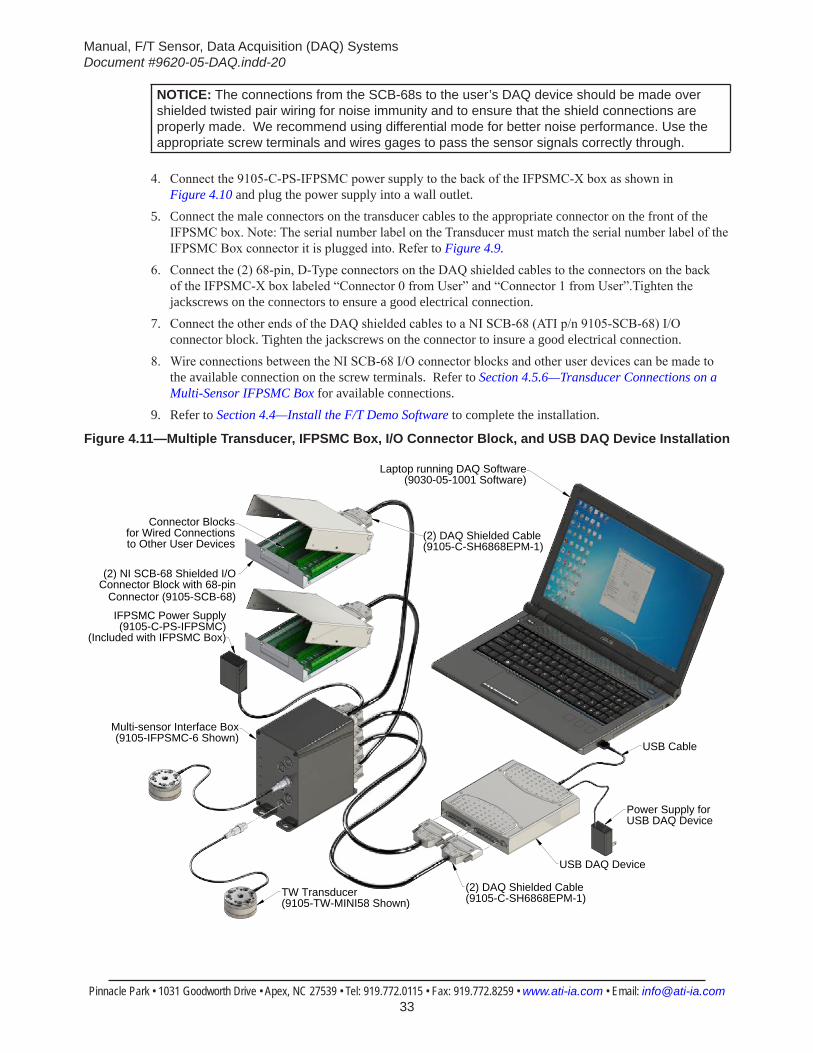
4. Connect the 9105-C-PS-IFPSMC power supply to the back of the IFPSMC-X box as shown in Figure 4.10 and plug the power supply into a wall outlet.
5. Connect the male connectors on the transducer cables to the appropriate connector on the front of the IFPSMC box. Note: The serial number label on the Transducer must match the serial number label of the IFPSMC Box connector it is plugged into. Refer to Figure 4.9.
6. Connect the (2) 68-pin, D-Type connectors on the DAQ shielded cables to the connectors on the back of the IFPSMC-X box labeled “Connector 0 from User” and “Connector 1 from User”.Tighten the jackscrews on the connectors to ensure a good electrical connection.
7. Connect the other ends of the DAQ shielded cables to a NI SCB-68 (ATI p/n 9105-SCB-68) I/O connector block. Tighten the jackscrews on the connector to insure a good electrical connection.
8. Wire connections between the NI SCB-68 I/O connector blocks and other user devices can be made to the available connection on the screw terminals. Refer to Section 4.5.6—Transducer Connections on a Multi-Sensor IFPSMC Box for available connections.
9. Refer to Section 4.4—Install the F/T Demo Software to complete the installation.
Figure 4.11—Multiple Transducer, IFPSMC Box, I/O Connector Block, and USB DAQ Device Installation
USB Cable
Laptop running DAQ Software(9030-05-1001 Software)
TW Transducer(9105-TW-MINI58 Shown)
Multi-sensor Interface Box(9105-IFPSMC-6 Shown)
USB DAQ Device
(2) NI SCB-68 Shielded I/O Connector Block with 68-pin
Connector (9105-SCB-68)
Connector Blocks for Wired Connections to Other User Devices
IFPSMC Power Supply(9105-C-PS-IFPSMC)
(Included with IFPSMC Box)
(2) DAQ Shielded Cable (9105-C-SH6868EPM-1)
(2) DAQ Shielded Cable (9105-C-SH6868EPM-1)
Power Supply forUSB DAQ Device
Manual, F/T Sensor, Data Acquisition (DAQ) SystemsDocument #9620-05-DAQ.indd-20
Pinnacle Park • 1031 Goodworth Drive • Apex, NC 27539 • Tel: 919.772.0115 • Fax: 919.772.8259 • www.ati-ia.com • Email: [email protected] 34
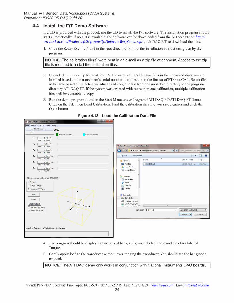
4.4 Install the F/T Demo SoftwareIf a CD is provided with the product, use the CD to install the F/T software. The installation program should start automatically. If no CD is available, the software can be downloaded from the ATI website at: http://www.ati-ia.com/Products/ft/Software/SysSoftwareTemplates.aspx click DAQ F/T to download the files.
1. Click the Setup.Exe file found in the root directory. Follow the installation instructions given by the program.
NOTICE: The calibration file(s) were sent in an e-mail as a zip file attachment. Access to the zip file is required to install the calibration files.
2. Unpack the FTxxxx.zip file sent from ATI in an e-mail. Calibration files in the unpacked directory are labelled based on the transducer’s serial number; the files are in the format of FTxxxx.CAL. Select file with name based on selected transducer and copy the file from the unpacked directory to the program directory ATI DAQ FT. If the system was ordered with more than one calibration, multiple calibration files will be available to copy.
3. Run the demo program found in the Start Menu under Programs\ATI DAQ FT\ATI DAQ FT Demo. Click on the File, then Load Calibration. Find the calibration data file you saved earlier and click the Open button.
Figure 4.12—Load the Calibration Data File
4. The program should be displaying two sets of bar graphs; one labeled Force and the other labeled
Torque.5. Gently apply load to the transducer without over-ranging the transducer. You should see the bar graphs
respond.
NOTICE: The ATI DAQ demo only works in conjunction with National Instruments DAQ boards.
Manual, F/T Sensor, Data Acquisition (DAQ) SystemsDocument #9620-05-DAQ.indd-20
Pinnacle Park • 1031 Goodworth Drive • Apex, NC 27539 • Tel: 919.772.0115 • Fax: 919.772.8259 • www.ati-ia.com • Email: [email protected] 35
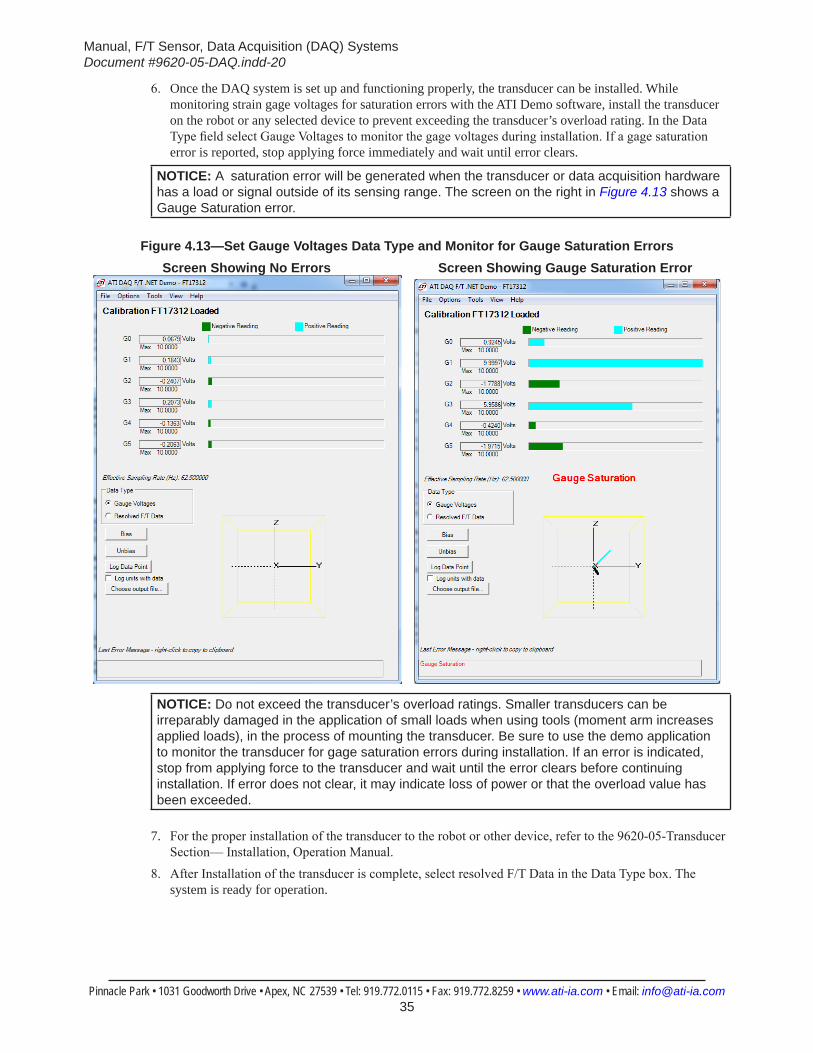
6. Once the DAQ system is set up and functioning properly, the transducer can be installed. While monitoring strain gage voltages for saturation errors with the ATI Demo software, install the transducer on the robot or any selected device to prevent exceeding the transducer’s overload rating. In the Data Type field select Gauge Voltages to monitor the gage voltages during installation. If a gage saturation error is reported, stop applying force immediately and wait until error clears.
NOTICE: A saturation error will be generated when the transducer or data acquisition hardware has a load or signal outside of its sensing range. The screen on the right in Figure 4.13 shows a Gauge Saturation error.
Figure 4.13—Set Gauge Voltages Data Type and Monitor for Gauge Saturation Errors Screen Showing No Errors Screen Showing Gauge Saturation Error
NOTICE: Do not exceed the transducer’s overload ratings. Smaller transducers can be irreparably damaged in the application of small loads when using tools (moment arm increases applied loads), in the process of mounting the transducer. Be sure to use the demo application to monitor the transducer for gage saturation errors during installation. If an error is indicated, stop from applying force to the transducer and wait until the error clears before continuing installation. If error does not clear, it may indicate loss of power or that the overload value has been exceeded.
7. For the proper installation of the transducer to the robot or other device, refer to the 9620-05-Transducer Section— Installation, Operation Manual.
8. After Installation of the transducer is complete, select resolved F/T Data in the Data Type box. The system is ready for operation.
Manual, F/T Sensor, Data Acquisition (DAQ) SystemsDocument #9620-05-DAQ.indd-20
Pinnacle Park • 1031 Goodworth Drive • Apex, NC 27539 • Tel: 919.772.0115 • Fax: 919.772.8259 • www.ati-ia.com • Email: [email protected] 36
4.5 Electrical Connection InformationThis section contains detailed information about the electrical connections of the various F/T system components.
NOTICE: Information in this section is intended for advanced users. Users whose systems include an ATI-supplied DAQ card may skip this section.
The ATI DAQ F/T software features a modular design allowing for use with any data acquisition system capable of electrically interfacing to the F/T System.
4.5.1 Signals and Power
CAUTION: The analog signals output by the transducer do not map directly into force and torque vectors. ATI DAQ F/T software with the calibration matrix must be used to convert these values into force and torque data.
Table 4.2—Signal DescriptionsSignal Name DescriptionSGx Output The non-inverting (positive) half of output of SGxSGx Reference The inverting (negative) half of output of SGx+VANA Positive power supply used by transducerAGnd Power supply return used by transducer-VANA Negative power supply used by transducer+5V 1 Positive power used by PS or IFPS box0V 1 Power supply return used by PS or IFPS box
AIGnd Analog Input Ground used for input current return from data acquisition card
Reserved This connection has an internal or future use. Do not use.Note:
1. Power to the PS / IFPS box can be provided from either a 5 V source through the 26-Pin connector or through the 12 V wall mounted power supply.
The PS and IFPS boxes include a 12 V wall mounted power supply. Power to the PS or IFPS box can be provided through either the 12 V wall-mounted power supply or a 5 V source to the 26-Pin connector. The PS box only requires one source; if both sources are connected, the PS box will use the 12 V source and the 5 V source will be ignored.Systems with an ATI-supplied DAQ card derive power from either the DAQ card or the 12 V wall mounted power supply. If using a customer supplied DAQ card, a 12 V wall-mounted power supply can be used, or a +5V and 0V power to the PS / IFPS box will need to be supplied. Without a PS box, the user will need to supply +VANA, AGnd , and -VANA power to the transducer. (Applicable to 9105-TIF transducers only; 9105-TW transducers require an IFPS box.)
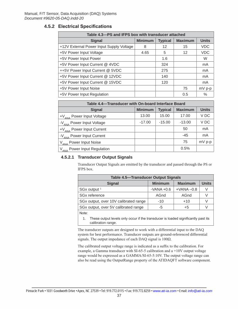
Manual, F/T Sensor, Data Acquisition (DAQ) SystemsDocument #9620-05-DAQ.indd-20
Pinnacle Park • 1031 Goodworth Drive • Apex, NC 27539 • Tel: 919.772.0115 • Fax: 919.772.8259 • www.ati-ia.com • Email: [email protected] 37
4.5.2 ElectricalSpecificationsTable 4.3—PS and IFPS box with transducer attached
Signal Minimum Typical Maximum Units+12V External Power Input Supply Voltage 8 12 15 VDC+5V Power Input Voltage 4.65 5 12 VDC+5V Power Input Power 1.6 W+5V Power Input Current @ 4VDC 324 mA++5V Power Input Current @ 5VDC 275 mA+5V Power Input Current @ 12VDC 140 mA+5V Power Input Current @ 15VDC 120 mA+5V Power Input Noise 75 mV p-p+5V Power Input Regulation 0.5 %
Table 4.4—Transducer with On-board Interface BoardSignal Minimum Typical Maximum Units
+VANA Power Input Voltage 13.00 15.00 17.00 V DC
-VANA Power Input Voltage -17.00 -15.00 -13.00 V DC
+VANA Power Input Current 50 mA
-VANA Power Input Current -45 mA
VANA Power Input Noise 75 mV p-p
VANA Power Input Regulation 0.5%
4.5.2.1 Transducer Output SignalsTransducer Output Signals are emitted by the transducer and passed through the PS or IFPS box.
Table 4.5—Transducer Output SignalsSignal Minimum Maximum Units
SGx output 1 -VANA +0.6 +VANA –0.8 VSGx reference AGnd AGnd VSGx output, over 10V calibrated range -10 +10 VSGx output, over 5V calibrated range -5 +5 VNote:
1. These output levels only occur if the transducer is loaded significantly past its calibration range.
The transducer outputs are designed to work with a differential input to the DAQ system for best performance. Transducer outputs are ground-referenced differential signals. The output impedance of each DAQ signal is 100Ω.
The calibrated output voltage range is indicated as a suffix to the calibration. For example, a Gamma transducer with SI-65-5 calibration and a +10V output voltage range would be expressed as a GAMMA/SI-65-5:10V. The output voltage range can also be read using the OutputRange property of the ATIDAQFT software component.
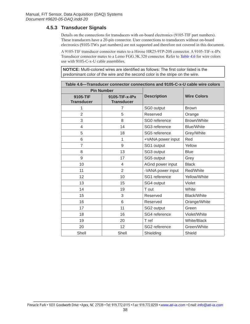
Manual, F/T Sensor, Data Acquisition (DAQ) SystemsDocument #9620-05-DAQ.indd-20
Pinnacle Park • 1031 Goodworth Drive • Apex, NC 27539 • Tel: 919.772.0115 • Fax: 919.772.8259 • www.ati-ia.com • Email: [email protected] 38
4.5.3 Transducer SignalsDetails on the connections for transducers with on-board electronics (9105-TIF part numbers). These transducers have a 20-pin connector. User connections to transducers without on-board electronics (9105-TWx part numbers) are not supported and therefore not covered in this document.A 9105-TIF transducer connector mates to a Hirose HR25-9TP-20S connector. A 9105-TIF-x-IPx Transducer connector mates to a Lemo FGG.3K.320 connector. Refer to Table 4.6 for wire colors use with 9105-C-x-U cable assemblies.
NOTICE: Multi-colored wires are identified as follows: The first color listed is the predominant color of the wire and the second color is the stripe on the wire.
Table 4.6—Transducer connector connections and 9105-C-x-U cable wire colorsPin Number
Description Wire Colors 9105-TIF Transducer
9105-TIF-x-IPx Transducer
1 7 SG0 output Brown2 5 Reserved Orange3 8 SG0 reference Brown/White4 14 SG3 reference Blue/White5 18 SG5 reference Grey/White6 1 +VANA power input Red7 9 SG1 output Yellow8 13 SG3 output Blue9 17 SG5 output Grey10 4 AGnd power input Black11 2 -VANA power input Red/White12 10 SG1 reference Yellow/White13 15 SG4 output Violet14 19 T out White15 3 Reserved Black/White16 6 Reserved Orange/White17 11 SG2 output Green18 16 SG4 reference Violet/White19 20 T ref White/Black20 12 SG2 reference Green/White
Shell Shell Shielding Shield
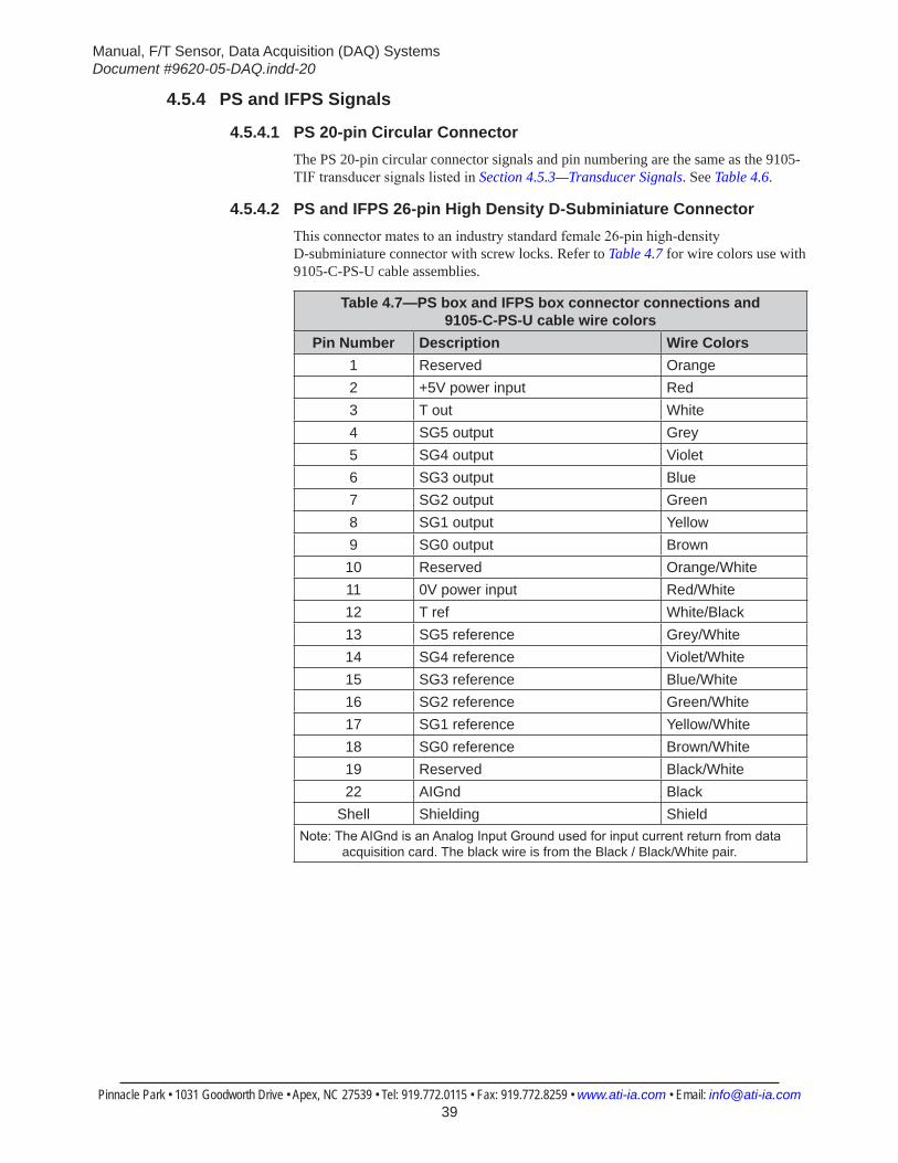
Manual, F/T Sensor, Data Acquisition (DAQ) SystemsDocument #9620-05-DAQ.indd-20
Pinnacle Park • 1031 Goodworth Drive • Apex, NC 27539 • Tel: 919.772.0115 • Fax: 919.772.8259 • www.ati-ia.com • Email: [email protected] 39
4.5.4 PS and IFPS Signals
4.5.4.1 PS 20-pin Circular ConnectorThe PS 20-pin circular connector signals and pin numbering are the same as the 9105-TIF transducer signals listed in Section 4.5.3—Transducer Signals. See Table 4.6.
4.5.4.2 PS and IFPS 26-pin High Density D-Subminiature ConnectorThis connector mates to an industry standard female 26-pin high-density D-subminiature connector with screw locks. Refer to Table 4.7 for wire colors use with 9105-C-PS-U cable assemblies.
Table 4.7—PS box and IFPS box connector connections and 9105-C-PS-U cable wire colors
Pin Number Description Wire Colors1 Reserved Orange2 +5V power input Red3 T out White4 SG5 output Grey5 SG4 output Violet6 SG3 output Blue7 SG2 output Green8 SG1 output Yellow9 SG0 output Brown10 Reserved Orange/White11 0V power input Red/White12 T ref White/Black13 SG5 reference Grey/White14 SG4 reference Violet/White15 SG3 reference Blue/White16 SG2 reference Green/White17 SG1 reference Yellow/White18 SG0 reference Brown/White19 Reserved Black/White22 AIGnd Black
Shell Shielding ShieldNote: The AIGnd is an Analog Input Ground used for input current return from data
acquisition card. The black wire is from the Black / Black/White pair.
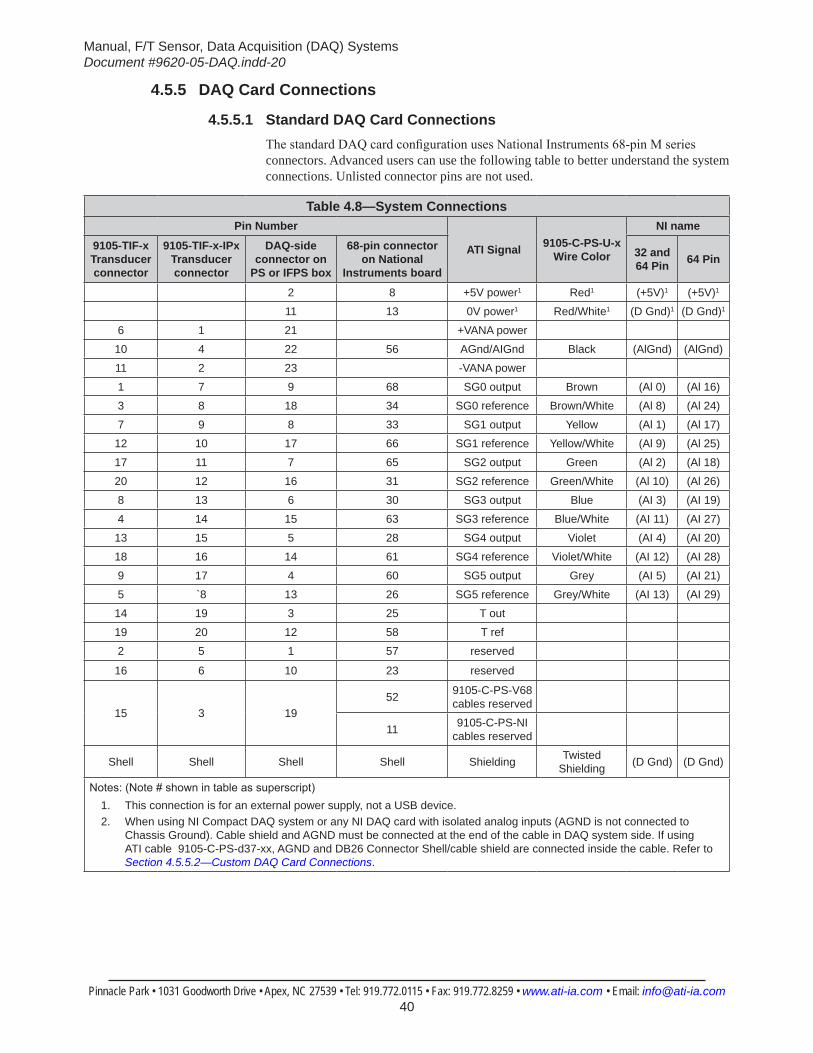
Manual, F/T Sensor, Data Acquisition (DAQ) SystemsDocument #9620-05-DAQ.indd-20
Pinnacle Park • 1031 Goodworth Drive • Apex, NC 27539 • Tel: 919.772.0115 • Fax: 919.772.8259 • www.ati-ia.com • Email: [email protected] 40
4.5.5 DAQ Card Connections
4.5.5.1 Standard DAQ Card ConnectionsThe standard DAQ card configuration uses National Instruments 68-pin M series connectors. Advanced users can use the following table to better understand the system connections. Unlisted connector pins are not used.
Table 4.8—System ConnectionsPin Number
ATI Signal 9105-C-PS-U-x Wire Color
NI name
9105-TIF-x Transducer connector
9105-TIF-x-IPx Transducer connector
DAQ-side connector on
PS or IFPS box
68-pin connector on National
Instruments board
32 and 64 Pin 64 Pin
2 8 +5V power1 Red1 (+5V)1 (+5V)1
11 13 0V power1 Red/White1 (D Gnd)1 (D Gnd)1
6 1 21 +VANA power
10 4 22 56 AGnd/AIGnd Black (AlGnd) (AlGnd)
11 2 23 -VANA power
1 7 9 68 SG0 output Brown (Al 0) (Al 16)
3 8 18 34 SG0 reference Brown/White (Al 8) (Al 24)
7 9 8 33 SG1 output Yellow (Al 1) (Al 17)
12 10 17 66 SG1 reference Yellow/White (Al 9) (Al 25)
17 11 7 65 SG2 output Green (Al 2) (Al 18)
20 12 16 31 SG2 reference Green/White (Al 10) (Al 26)
8 13 6 30 SG3 output Blue (AI 3) (AI 19)
4 14 15 63 SG3 reference Blue/White (AI 11) (AI 27)
13 15 5 28 SG4 output Violet (AI 4) (AI 20)
18 16 14 61 SG4 reference Violet/White (AI 12) (AI 28)
9 17 4 60 SG5 output Grey (AI 5) (AI 21)
5 `8 13 26 SG5 reference Grey/White (AI 13) (AI 29)
14 19 3 25 T out
19 20 12 58 T ref
2 5 1 57 reserved
16 6 10 23 reserved
15 3 1952 9105-C-PS-V68
cables reserved
11 9105-C-PS-NI cables reserved
Shell Shell Shell Shell Shielding Twisted Shielding (D Gnd) (D Gnd)
Notes: (Note # shown in table as superscript)1. This connection is for an external power supply, not a USB device.2. When using NI Compact DAQ system or any NI DAQ card with isolated analog inputs (AGND is not connected to
Chassis Ground). Cable shield and AGND must be connected at the end of the cable in DAQ system side. If using ATI cable 9105-C-PS-d37-xx, AGND and DB26 Connector Shell/cable shield are connected inside the cable. Refer to Section 4.5.5.2—Custom DAQ Card Connections.
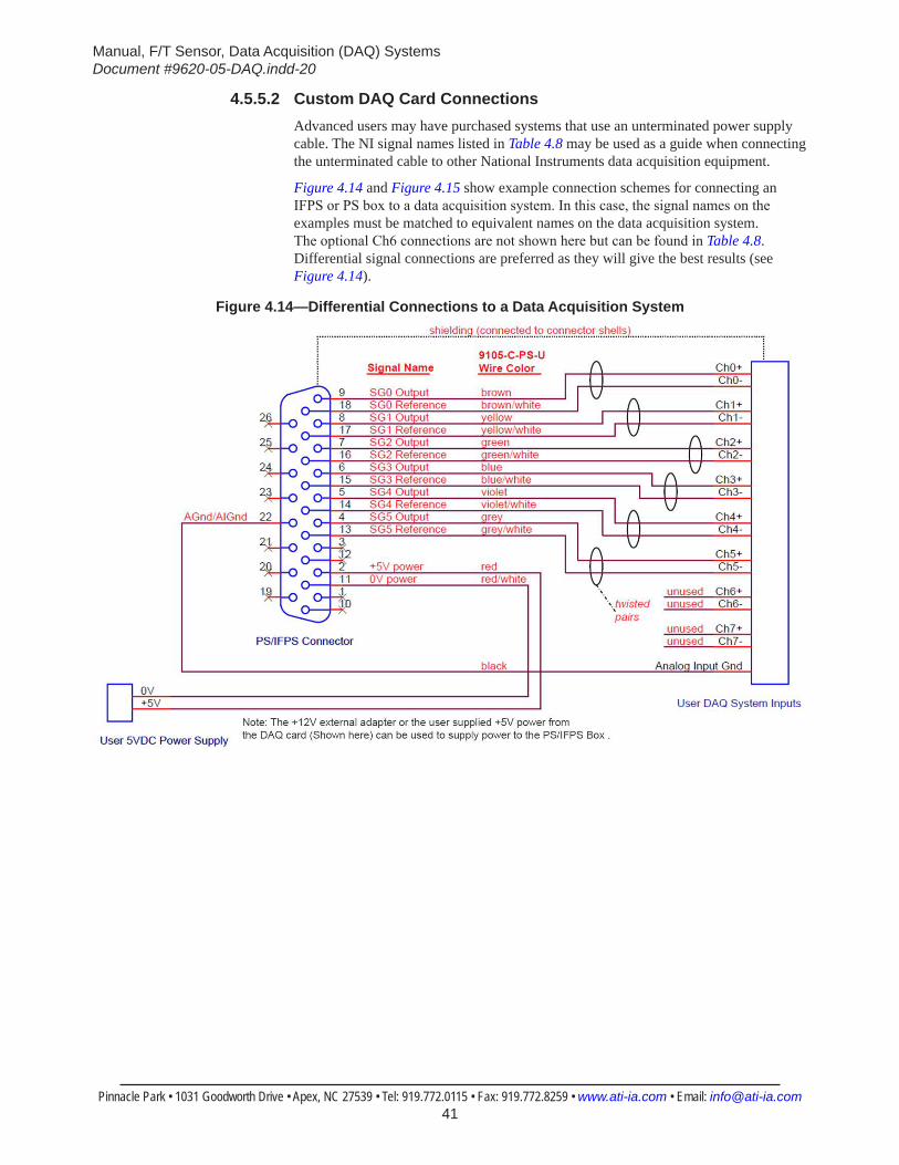
Manual, F/T Sensor, Data Acquisition (DAQ) SystemsDocument #9620-05-DAQ.indd-20
Pinnacle Park • 1031 Goodworth Drive • Apex, NC 27539 • Tel: 919.772.0115 • Fax: 919.772.8259 • www.ati-ia.com • Email: [email protected] 41
4.5.5.2 Custom DAQ Card ConnectionsAdvanced users may have purchased systems that use an unterminated power supply cable. The NI signal names listed in Table 4.8 may be used as a guide when connecting the unterminated cable to other National Instruments data acquisition equipment.
Figure 4.14 and Figure 4.15 show example connection schemes for connecting an IFPS or PS box to a data acquisition system. In this case, the signal names on the examples must be matched to equivalent names on the data acquisition system. The optional Ch6 connections are not shown here but can be found in Table 4.8. Differential signal connections are preferred as they will give the best results (see Figure 4.14).
Figure 4.14—Differential Connections to a Data Acquisition System
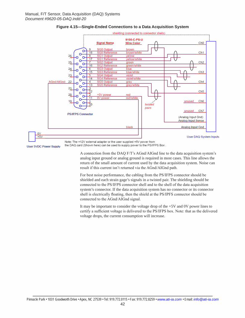
Manual, F/T Sensor, Data Acquisition (DAQ) SystemsDocument #9620-05-DAQ.indd-20
Pinnacle Park • 1031 Goodworth Drive • Apex, NC 27539 • Tel: 919.772.0115 • Fax: 919.772.8259 • www.ati-ia.com • Email: [email protected] 42
Figure 4.15—Single-Ended Connections to a Data Acquisition System
A connection from the DAQ F/T’s AGnd/AIGnd line to the data acquisition system’s analog input ground or analog ground is required in most cases. This line allows the return of the small amount of current used by the data acquisition system. Noise can result if this current isn’t returned via the AGnd/AIGnd path.
For best noise performance, the cabling from the PS/IFPS connector should be shielded and each strain gage’s signals in a twisted pair. The shielding should be connected to the PS/IFPS connector shell and to the shell of the data acquisition system’s connector. If the data acquisition system has no connector or its connector shell is electrically floating, then the shield at the PS/IPFS connector should be connected to the AGnd/AIGnd signal.
It may be important to consider the voltage drop of the +5V and 0V power lines to certify a sufficient voltage is delivered to the PS/IFPS box. Note: that as the delivered voltage drops, the current consumption will increase.
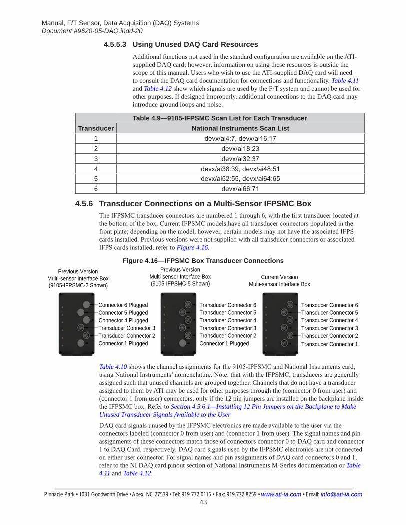
Manual, F/T Sensor, Data Acquisition (DAQ) SystemsDocument #9620-05-DAQ.indd-20
Pinnacle Park • 1031 Goodworth Drive • Apex, NC 27539 • Tel: 919.772.0115 • Fax: 919.772.8259 • www.ati-ia.com • Email: [email protected] 43
4.5.5.3 Using Unused DAQ Card ResourcesAdditional functions not used in the standard configuration are available on the ATI-supplied DAQ card; however, information on using these resources is outside the scope of this manual. Users who wish to use the ATI-supplied DAQ card will need to consult the DAQ card documentation for connections and functionality. Table 4.11 and Table 4.12 show which signals are used by the F/T system and cannot be used for other purposes. If designed improperly, additional connections to the DAQ card may introduce ground loops and noise.
Table 4.9—9105-IFPSMC Scan List for Each TransducerTransducer National Instruments Scan List
1 devx/ai4:7, devx/ai16:172 devx/ai18:233 devx/ai32:374 devx/ai38:39, devx/ai48:515 devx/ai52:55, devx/ai64:656 devx/ai66:71
4.5.6 Transducer Connections on a Multi-Sensor IFPSMC BoxThe IFPSMC transducer connectors are numbered 1 through 6, with the first transducer located at the bottom of the box. Current IFPSMC models have all transducer connectors populated in the front plate; depending on the model, however, certain models may not have the associated IFPS cards installed. Previous versions were not supplied with all transducer connectors or associated IFPS cards installed, refer to Figure 4.16.
Figure 4.16—IFPSMC Box Transducer Connections
Current VersionMulti-sensor Interface Box
Transducer Connector 1Transducer Connector 2Transducer Connector 3Transducer Connector 4Transducer Connector 5Transducer Connector 6Transducer Connector 6
Transducer Connector 5Transducer Connector 4Transducer Connector 3Transducer Connector 2Connector 1 PluggedConnector 1 Plugged
Transducer Connector 2Transducer Connector 3Connector 4 PluggedConnector 5 PluggedConnector 6 Plugged
(9105-IFPSMC-5 Shown)
Previous VersionMulti-sensor Interface Box(9105-IFPSMC-2 Shown)
Previous VersionMulti-sensor Interface Box
Table 4.10 shows the channel assignments for the 9105-IPFSMC and National Instruments card, using National Instruments’ nomenclature. Note: that with the IFPSMC, transducers are generally assigned such that unused channels are grouped together. Channels that do not have a transducer assigned to them by ATI may be used for other purposes through the (connector 0 from user) and (connector 1 from user) connectors, only if the 12 pin jumpers are installed on the backplane inside the IFPSMC box. Refer to Section 4.5.6.1—Installing 12 Pin Jumpers on the Backplane to Make Unused Transducer Signals Available to the UserDAQ card signals unused by the IFPSMC electronics are made available to the user via the connectors labeled (connector 0 from user) and (connector 1 from user). The signal names and pin assignments of these connectors match those of connectors connector 0 to DAQ card and connector 1 to DAQ Card, respectively. DAQ card signals used by the IFPSMC electronics are not connected on either user connector. For signal names and pin assignments of DAQ card connectors 0 and 1, refer to the NI DAQ card pinout section of National Instruments M-Series documentation or Table 4.11 and Table 4.12.
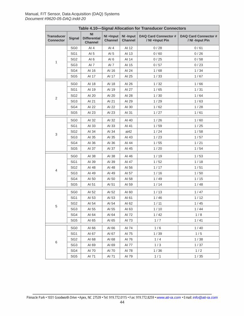
Manual, F/T Sensor, Data Acquisition (DAQ) SystemsDocument #9620-05-DAQ.indd-20
Pinnacle Park • 1031 Goodworth Drive • Apex, NC 27539 • Tel: 919.772.0115 • Fax: 919.772.8259 • www.ati-ia.com • Email: [email protected] 44
Table 4.10—Signal Allocation for Transducer Connectors
Transducer Connector Signal
NI Differential
Channel
NI +Input Channel
NI -Input Channel
DAQ Card Connector # / NI +Input Pin
DAQ Card Connector # / NI -Input Pin
1
SG0 AI 4 AI 4 AI 12 0 / 28 0 / 61
SG1 AI 5 AI 5 AI 13 0 / 60 0 / 26
SG2 AI 6 AI 6 AI 14 0 / 25 0 / 58
SG3 AI 7 AI 7 AI 15 0 / 57 0 / 23
SG4 AI 16 AI 16 AI 24 1 / 68 1 / 34
SG5 AI 17 AI 17 AI 25 1 / 33 1 / 67
2
SG0 AI 18 AI 18 AI 26 1 / 32 1 / 66
SG1 AI 19 AI 19 AI 27 1 / 65 1 / 31
SG2 AI 20 AI 20 AI 28 1 / 30 1 / 64
SG3 AI 21 AI 21 AI 29 1 / 29 1 / 63
SG4 AI 22 AI 22 AI 30 1 / 62 1 / 28
SG5 AI 23 AI 23 AI 31 1 / 27 1 / 61
3
SG0 AI 32 AI 32 AI 40 1 / 26 1 / 60
SG1 AI 33 AI 33 AI 41 1 / 59 1 / 25
SG2 AI 34 AI 34 ai42 1 / 24 1 / 58
SG3 AI 35 AI 35 AI 43 1 / 23 1 / 57
SG4 AI 36 AI 36 AI 44 1 / 55 1 / 21
SG5 AI 37 AI 37 AI 45 1 / 20 1 / 54
4
SG0 AI 38 AI 38 AI 46 1 / 19 1 / 53
SG1 AI 39 AI 39 AI 47 1 / 52 1 / 18
SG2 AI 48 AI 48 AI 56 1 / 17 1 / 51
SG3 AI 49 AI 49 AI 57 1 / 16 1 / 50
SG4 AI 50 AI 50 AI 58 1 / 49 1 / 15
SG5 AI 51 AI 51 AI 59 1 / 14 1 / 48
5
SG0 AI 52 AI 52 AI 60 1 / 13 1 / 47
SG1 AI 53 AI 53 AI 61 1 / 46 1 / 12
SG2 AI 54 AI 54 AI 62 1 / 11 1 / 45
SG3 AI 55 AI 55 AI 63 1 / 10 1 / 44
SG4 AI 64 AI 64 AI 72 1 / 42 1 / 8
SG5 AI 65 AI 65 AI 73 1 / 7 1 / 41
6
SG0 AI 66 AI 66 AI 74 1 / 6 1 / 40
SG1 AI 67 AI 67 AI 75 1 / 39 1 / 5
SG2 AI 68 AI 68 AI 76 1 / 4 1 / 38
SG3 AI 69 AI 69 AI 77 1 / 3 1 / 37
SG4 AI 70 AI 70 AI 78 1 / 36 1 / 2
SG5 AI 71 AI 71 AI 79 1 / 1 1 / 35
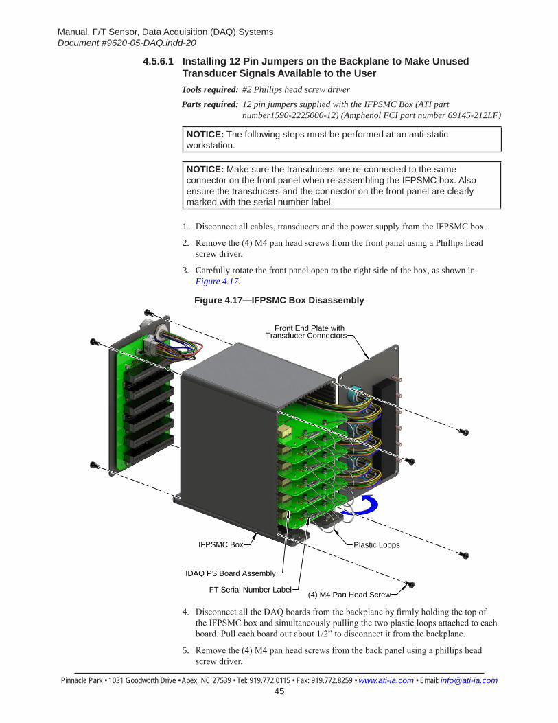
Manual, F/T Sensor, Data Acquisition (DAQ) SystemsDocument #9620-05-DAQ.indd-20
Pinnacle Park • 1031 Goodworth Drive • Apex, NC 27539 • Tel: 919.772.0115 • Fax: 919.772.8259 • www.ati-ia.com • Email: [email protected] 45
4.5.6.1 Installing 12 Pin Jumpers on the Backplane to Make Unused Transducer Signals Available to the UserTools required: #2 Phillips head screw driverParts required: 12 pin jumpers supplied with the IFPSMC Box (ATI part
number1590-2225000-12) (Amphenol FCI part number 69145-212LF)
NOTICE: The following steps must be performed at an anti-static workstation.
NOTICE: Make sure the transducers are re-connected to the same connector on the front panel when re-assembling the IFPSMC box. Also ensure the transducers and the connector on the front panel are clearly marked with the serial number label.
1. Disconnect all cables, transducers and the power supply from the IFPSMC box.
2. Remove the (4) M4 pan head screws from the front panel using a Phillips head screw driver.
3. Carefully rotate the front panel open to the right side of the box, as shown in Figure 4.17.
Figure 4.17—IFPSMC Box Disassembly
(4) M4 Pan Head Screw
Front End Plate with Transducer Connectors
IFPSMC Box
IDAQ PS Board Assembly
Plastic Loops
FT Serial Number Label
4. Disconnect all the DAQ boards from the backplane by firmly holding the top of the IFPSMC box and simultaneously pulling the two plastic loops attached to each board. Pull each board out about 1/2” to disconnect it from the backplane.
5. Remove the (4) M4 pan head screws from the back panel using a phillips head screw driver.
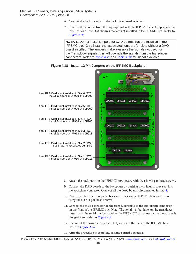
Manual, F/T Sensor, Data Acquisition (DAQ) SystemsDocument #9620-05-DAQ.indd-20
Pinnacle Park • 1031 Goodworth Drive • Apex, NC 27539 • Tel: 919.772.0115 • Fax: 919.772.8259 • www.ati-ia.com • Email: [email protected] 46
6. Remove the back panel with the backplane board attached.
7. Remove the jumpers from the bag supplied with the IFPSMC box. Jumpers can be installed for all the DAQ boards that are not installed in the IFPSMC box. Refer to Figure 4.18.
NOTICE: Do not install jumpers for DAQ boards that are installed in the IFPSMC box. Only install the associated jumpers for slots without a DAQ board installed. The jumpers make available the signals not used for the Transducer signals, this will override the signals from the transducer connectors. Refer to Table 4.11 and Table 4.12 for signal available.
Figure 4.18—Install 12 Pin Jumpers on the IFPSMC Backplane
JP908
JP904 JP905JP913JP912
JP907JP906 JP909
JP910JP911
If an IFPS Card is not installed in Slot 1 (TC1)Install Jumpers on JP910 and JP911
If an IFPS Card is not installed in Slot 2 (TC2)Slot 2 has no associated Jumpers
If an IFPS Card is not installed in Slot 3 (TC3)Install Jumpers on JP912 and JP913
If an IFPS Card is not installed in Slot 4 (TC4)Install Jumpers on JP904 and JP905
If an IFPS Card is not installed in Slot 5 (TC5)Install Jumpers on JP906 and JP907
If an IFPS Card is not installed in Slot 6 (TC6)Install Jumpers on JP908 and JP909
8. Attach the back panel to the IFPSMC box, secure with the (4) M4 pan head screws.
9. Connect the DAQ boards to the backplane by pushing them in until they seat into the backplane connector. Connect all the DAQ boards disconnected in step 4.
10. Carefully rotate the front panel back into place on the IFPSMC box and secure using the (4) M4 pan head screws,
11. Connect the male connector on the transducer cable to the appropriate connector on the front of the IFPSMC box. Note: The serial number label on the transducer must match the serial number label on the IFPSMC Box connector the transducer is plugged into. Refer to Figure 4.9.
12. Reconnect the power supply and DAQ cables to the back of the IFPSMC box. Refer to Figure 4.25.
13. After the procedure is complete, resume normal operation.
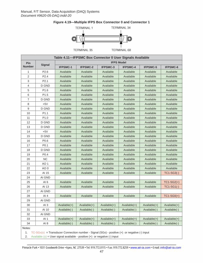
Manual, F/T Sensor, Data Acquisition (DAQ) SystemsDocument #9620-05-DAQ.indd-20
Pinnacle Park • 1031 Goodworth Drive • Apex, NC 27539 • Tel: 919.772.0115 • Fax: 919.772.8259 • www.ati-ia.com • Email: [email protected] 47
Figure 4.19—Multiple IFPS Box Connector 0 and Connector 1
Table 4.11—IFPSMC Box Connector 0 User Signals AvailablePin
Number SignalIFPS Model
IFPSMC-1 IFPSMC-2 IFPSMC-3 IFPSMC-4 IFPSMC-5 IFPSMC-61 P2.6 Available Available Available Available Available Available2 P2.4 Available Available Available Available Available Available3 P2.1 Available Available Available Available Available Available4 D GND Available Available Available Available Available Available5 P1.6 Available Available Available Available Available Available6 P1.5 Available Available Available Available Available Available7 D GND Available Available Available Available Available Available8 +5V Available Available Available Available Available Available9 D GND Available Available Available Available Available Available10 P1.1 Available Available Available Available Available Available11 P1.0 Available Available Available Available Available Available12 D GND Available Available Available Available Available Available13 D GND Available Available Available Available Available Available14 +5V Available Available Available Available Available Available15 D GND Available Available Available Available Available Available16 P0.6 Available Available Available Available Available Available17 P0.1 Available Available Available Available Available Available18 D GND Available Available Available Available Available Available19 P0.4 Available Available Available Available Available Available20 NC Available Available Available Available Available Available21 AO 1 Available Available Available Available Available Available22 AO 0 Available Available Available Available Available Available23 AI 15 Available Available Available Available Available TC1-SG3(-)24 AI GND25 AI 6 Available Available Available Available Available TC1-SG2(+)26 AI 13 Available Available Available Available Available TC1-SG1(-)27 AI GND28 AI 4 Available Available Available Available Available TC1-SG0(+)29 AI GND30 AI 3 Available(+) Available(+) Available(+) Available(+) Available(+) Available(+)31 AI 10 Available(-) Available(-) Available(-) Available(-) Available(-) Available(-)32 AI GND33 AI 1 Available(+) Available(+) Available(+) Available(+) Available(+) Available(+)34 AI 8 Available(-) Available(-) Available(-) Available(-) Available(-) Available(-)
Notes:1. TC-SGx(x) = Transducer Connection number - Signal (SGx) - positive (+) or negative (-) input2. Available (x) = User signal available - positive (+) or negative (-) input
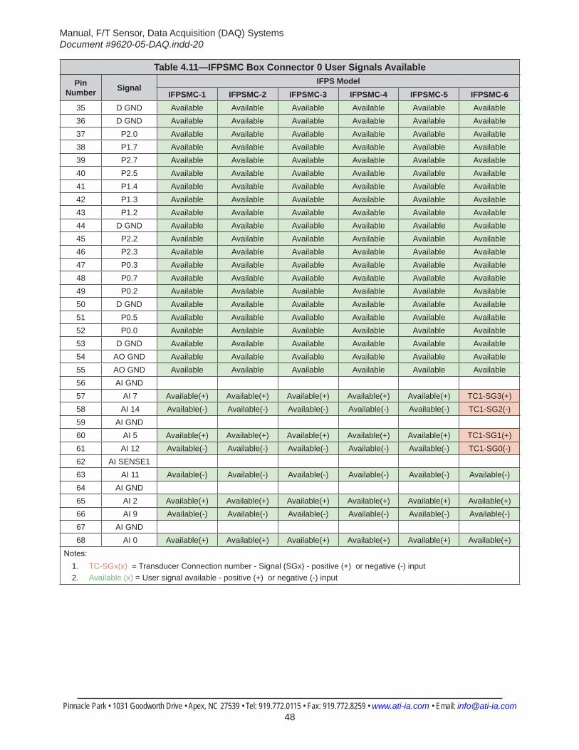
Manual, F/T Sensor, Data Acquisition (DAQ) SystemsDocument #9620-05-DAQ.indd-20
Pinnacle Park • 1031 Goodworth Drive • Apex, NC 27539 • Tel: 919.772.0115 • Fax: 919.772.8259 • www.ati-ia.com • Email: [email protected] 48
Table 4.11—IFPSMC Box Connector 0 User Signals AvailablePin
Number SignalIFPS Model
IFPSMC-1 IFPSMC-2 IFPSMC-3 IFPSMC-4 IFPSMC-5 IFPSMC-635 D GND Available Available Available Available Available Available36 D GND Available Available Available Available Available Available37 P2.0 Available Available Available Available Available Available38 P1.7 Available Available Available Available Available Available39 P2.7 Available Available Available Available Available Available40 P2.5 Available Available Available Available Available Available41 P1.4 Available Available Available Available Available Available42 P1.3 Available Available Available Available Available Available43 P1.2 Available Available Available Available Available Available44 D GND Available Available Available Available Available Available45 P2.2 Available Available Available Available Available Available46 P2.3 Available Available Available Available Available Available47 P0.3 Available Available Available Available Available Available48 P0.7 Available Available Available Available Available Available49 P0.2 Available Available Available Available Available Available50 D GND Available Available Available Available Available Available51 P0.5 Available Available Available Available Available Available52 P0.0 Available Available Available Available Available Available53 D GND Available Available Available Available Available Available54 AO GND Available Available Available Available Available Available55 AO GND Available Available Available Available Available Available56 AI GND57 AI 7 Available(+) Available(+) Available(+) Available(+) Available(+) TC1-SG3(+)58 AI 14 Available(-) Available(-) Available(-) Available(-) Available(-) TC1-SG2(-)59 AI GND60 AI 5 Available(+) Available(+) Available(+) Available(+) Available(+) TC1-SG1(+)61 AI 12 Available(-) Available(-) Available(-) Available(-) Available(-) TC1-SG0(-)62 AI SENSE163 AI 11 Available(-) Available(-) Available(-) Available(-) Available(-) Available(-)64 AI GND65 AI 2 Available(+) Available(+) Available(+) Available(+) Available(+) Available(+)66 AI 9 Available(-) Available(-) Available(-) Available(-) Available(-) Available(-)67 AI GND68 AI 0 Available(+) Available(+) Available(+) Available(+) Available(+) Available(+)
Notes:1. TC-SGx(x) = Transducer Connection number - Signal (SGx) - positive (+) or negative (-) input2. Available (x) = User signal available - positive (+) or negative (-) input
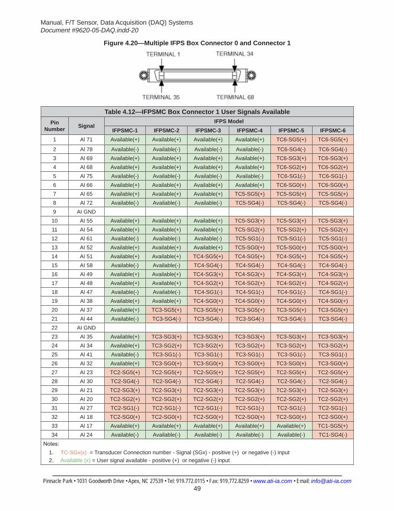
Manual, F/T Sensor, Data Acquisition (DAQ) SystemsDocument #9620-05-DAQ.indd-20
Pinnacle Park • 1031 Goodworth Drive • Apex, NC 27539 • Tel: 919.772.0115 • Fax: 919.772.8259 • www.ati-ia.com • Email: [email protected] 49
Figure 4.20—Multiple IFPS Box Connector 0 and Connector 1
Table 4.12—IFPSMC Box Connector 1 User Signals AvailablePin
Number SignalIFPS Model
IFPSMC-1 IFPSMC-2 IFPSMC-3 IFPSMC-4 IFPSMC-5 IFPSMC-61 Al 71 Available(+) Available(+) Available(+) Available(+) TC6-SG5(+) TC6-SG5(+)
2 Al 78 Available(-) Available(-) Available(-) Available(-) TC6-SG4(-) TC6-SG4(-)3 Al 69 Available(+) Available(+) Available(+) Available(+) TC6-SG3(+) TC6-SG3(+)4 Al 68 Available(+) Available(+) Available(+) Available(+) TC6-SG2(+) TC6-SG2(+)5 Al 75 Available(-) Available(-) Available(-) Available(-) TC6-SG1(-) TC6-SG1(-)6 Al 66 Available(+) Available(+) Available(+) Available(+) TC6-SG0(+) TC6-SG0(+)7 Al 65 Available(+) Available(+) Available(+) TC5-SG5(+) TC5-SG5(+) TC5-SG5(+)8 Al 72 Available(-) Available(-) Available(-) TC5-SG4(-) TC5-SG4(-) TC5-SG4(-)9 AI GND
10 AI 55 Available(+) Available(+) Available(+) TC5-SG3(+) TC5-SG3(+) TC5-SG3(+)11 AI 54 Available(+) Available(+) Available(+) TC5-SG2(+) TC5-SG2(+) TC5-SG2(+)12 Al 61 Available(-) Available(-) Available(-) TC5-SG1(-) TC5-SG1(-) TC5-SG1(-)13 AI 52 Available(+) Available(+) Available(+) TC5-SG0(+) TC5-SG0(+) TC5-SG0(+)14 AI 51 Available(+) Available(+) TC4-SG5(+) TC4-SG5(+) TC4-SG5(+) TC4-SG5(+)15 AI 58 Available(-) Available(-) TC4-SG4(-) TC4-SG4(-) TC4-SG4(-) TC4-SG4(-)16 Al 49 Available(+) Available(+) TC4-SG3(+) TC4-SG3(+) TC4-SG3(+) TC4-SG3(+)17 Al 48 Available(+) Available(+) TC4-SG2(+) TC4-SG2(+) TC4-SG2(+) TC4-SG2(+)18 Al 47 Available(-) Available(-) TC4-SG1(-) TC4-SG1(-) TC4-SG1(-) TC4-SG1(-)19 Al 38 Available(+) Available(+) TC4-SG0(+) TC4-SG0(+) TC4-SG0(+) TC4-SG0(+)20 Al 37 Available(+) TC3-SG5(+) TC3-SG5(+) TC3-SG5(+) TC3-SG5(+) TC3-SG5(+)21 Al 44 Available(-) TC3-SG4(-) TC3-SG4(-) TC3-SG4(-) TC3-SG4(-) TC3-SG4(-)22 AI GND23 Al 35 Available(+) TC3-SG3(+) TC3-SG3(+) TC3-SG3(+) TC3-SG3(+) TC3-SG3(+)24 Al 34 Available(+) TC3-SG2(+) TC3-SG2(+) TC3-SG2(+) TC3-SG2(+) TC3-SG2(+)25 Al 41 Available(-) TC3-SG1(-) TC3-SG1(-) TC3-SG1(-) TC3-SG1(-) TC3-SG1(-)26 Al 32 Available(+) TC3-SG0(+) TC3-SG0(+) TC3-SG0(+) TC3-SG0(+) TC3-SG0(+)27 AI 23 TC2-SG5(+) TC2-SG5(+) TC2-SG5(+) TC2-SG5(+) TC2-SG5(+) TC2-SG5(+)28 AI 30 TC2-SG4(-) TC2-SG4(-) TC2-SG4(-) TC2-SG4(-) TC2-SG4(-) TC2-SG4(-)29 AI 21 TC2-SG3(+) TC2-SG3(+) TC2-SG3(+) TC2-SG3(+) TC2-SG3(+) TC2-SG3(+)30 AI 20 TC2-SG2(+) TC2-SG2(+) TC2-SG2(+) TC2-SG2(+) TC2-SG2(+) TC2-SG2(+)31 AI 27 TC2-SG1(-) TC2-SG1(-) TC2-SG1(-) TC2-SG1(-) TC2-SG1(-) TC2-SG1(-)32 AI 18 TC2-SG0(+) TC2-SG0(+) TC2-SG0(+) TC2-SG0(+) TC2-SG0(+) TC2-SG0(+)33 Al 17 Available(+) Available(+) Available(+) Available(+) Available(+) TC1-SG5(+)34 Al 24 Available(-) Available(-) Available(-) Available(-) Available(-) TC1-SG4(-)
Notes:1. TC-SGx(x) = Transducer Connection number - Signal (SGx) - positive (+) or negative (-) input2. Available (x) = User signal available - positive (+) or negative (-) input
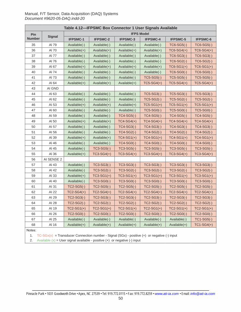
Manual, F/T Sensor, Data Acquisition (DAQ) SystemsDocument #9620-05-DAQ.indd-20
Pinnacle Park • 1031 Goodworth Drive • Apex, NC 27539 • Tel: 919.772.0115 • Fax: 919.772.8259 • www.ati-ia.com • Email: [email protected] 50
Table 4.12—IFPSMC Box Connector 1 User Signals AvailablePin
Number SignalIFPS Model
IFPSMC-1 IFPSMC-2 IFPSMC-3 IFPSMC-4 IFPSMC-5 IFPSMC-635 Al 79 Available(-) Available(-) Available(-) Available(-) TC6-SG5(-) TC6-SG5(-)36 Al 70 Available(+) Available(+) Available(+) Available(+) TC6-SG4(+) TC6-SG4(+)37 Al 77 Available(-) Available(-) Available(-) Available(-) TC6-SG3(-) TC6-SG3(-)38 Al 76 Available(-) Available(-) Available(-) Available(-) TC6-SG2(-) TC6-SG2(-)39 Al 67 Available(+) Available(+) Available(+) Available(+) TC6-SG1(+) TC6-SG1(+)40 Al 74 Available(-) Available(-) Available(-) Available(-) TC6-SG0(-) TC6-SG0(-)41 Al 73 Available(-) Available(-) Available(-) TC5-SG5(-) TC5-SG5(-) TC5-SG5(-)42 Al 64 Available(+) Available(+) Available(+) TC5-SG4(+) TC5-SG4(+) TC5-SG4(+)43 AI GND44 Al 63 Available(-) Available(-) Available(-) TC5-SG3(-) TC5-SG3(-) TC5-SG3(-)45 Al 62 Available(-) Available(-) Available(-) TC5-SG2(-) TC5-SG2(-) TC5-SG2(-)46 AI 53 Available(+) Available(+) Available(+) TC5-SG1(+) TC5-SG1(+) TC5-SG1(+)47 Al 60 Available(-) Available(-) Available(-) TC5-SG0(-) TC5-SG0(-) TC5-SG0(-)48 AI 59 Available(-) Available(-) TC4-SG5(-) TC4-SG5(-) TC4-SG5(-) TC4-SG5(-)
49 Al 50 Available(+) Available(+) TC4-SG4(+) TC4-SG4(+) TC4-SG4(+) TC4-SG4(+)50 AI 57 Available(-) Available(-) TC4-SG3(-) TC4-SG3(-) TC4-SG3(-) TC4-SG3(-)51 AI 56 Available(-) Available(-) TC4-SG2(-) TC4-SG2(-) TC4-SG2(-) TC4-SG2(-)52 Al 39 Available(+) Available(+) TC4-SG1(+) TC4-SG1(+) TC4-SG1(+) TC4-SG1(+)53 Al 46 Available(-) Available(-) TC4-SG0(-) TC4-SG0(-) TC4-SG0(-) TC4-SG0(-)54 Al 45 Available(-) TC3-SG5(-) TC3-SG5(-) TC3-SG5(-) TC3-SG5(-) TC3-SG5(-)55 Al 36 Available(+) TC3-SG4(+) TC3-SG4(+) TC3-SG4(+) TC3-SG4(+) TC3-SG4(+)56 AI SENSE 257 Al 43 Available(-) TC3-SG3(-) TC3-SG3(-) TC3-SG3(-) TC3-SG3(-) TC3-SG3(-)58 Al 42 Available(-) TC3-SG2(-) TC3-SG2(-) TC3-SG2(-) TC3-SG2(-) TC3-SG2(-)59 Al 33 Available(+) TC3-SG1(+) TC3-SG1(+) TC3-SG1(+) TC3-SG1(+) TC3-SG1(+)60 Al 40 Available(-) TC3-SG0(-) TC3-SG0(-) TC3-SG0(-) TC3-SG0(-) TC3-SG0(-)61 AI 31 TC2-SG5(-) TC2-SG5(-) TC2-SG5(-) TC2-SG5(-) TC2-SG5(-) TC2-SG5(-)62 AI 22 TC2-SG4(+) TC2-SG4(+) TC2-SG4(+) TC2-SG4(+) TC2-SG4(+) TC2-SG4(+)63 AI 29 TC2-SG3(-) TC2-SG3(-) TC2-SG3(-) TC2-SG3(-) TC2-SG3(-) TC2-SG3(-)64 AI 28 TC2-SG2(-) TC2-SG2(-) TC2-SG2(-) TC2-SG2(-) TC2-SG2(-) TC2-SG2(-)65 AI 19 TC2-SG1(+) TC2-SG1(+) TC2-SG1(+) TC2-SG1(+) TC2-SG1(+) TC2-SG1(+)66 AI 26 TC2-SG0(-) TC2-SG0(-) TC2-SG0(-) TC2-SG0(-) TC2-SG0(-) TC2-SG0(-)67 Al 25 Available(-) Available(-) Available(-) Available(-) Available(-) TC1-SG5(-)68 Al 16 Available(+) Available(+) Available(+) Available(+) Available(+) TC1-SG4(+)
Notes:1. TC-SGx(x) = Transducer Connection number - Signal (SGx) - positive (+) or negative (-) input2. Available (x) = User signal available - positive (+) or negative (-) input
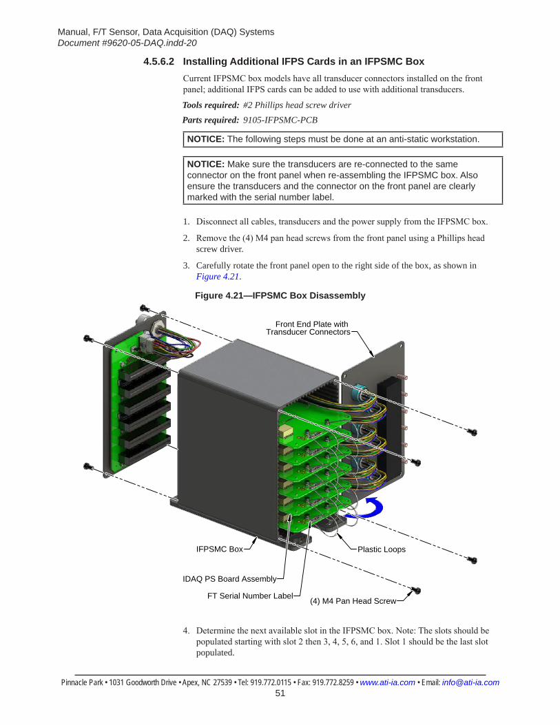
Manual, F/T Sensor, Data Acquisition (DAQ) SystemsDocument #9620-05-DAQ.indd-20
Pinnacle Park • 1031 Goodworth Drive • Apex, NC 27539 • Tel: 919.772.0115 • Fax: 919.772.8259 • www.ati-ia.com • Email: [email protected] 51
4.5.6.2 Installing Additional IFPS Cards in an IFPSMC BoxCurrent IFPSMC box models have all transducer connectors installed on the front panel; additional IFPS cards can be added to use with additional transducers.
Tools required: #2 Phillips head screw driverParts required: 9105-IFPSMC-PCB
NOTICE: The following steps must be done at an anti-static workstation.
NOTICE: Make sure the transducers are re-connected to the same connector on the front panel when re-assembling the IFPSMC box. Also ensure the transducers and the connector on the front panel are clearly marked with the serial number label.
1. Disconnect all cables, transducers and the power supply from the IFPSMC box.
2. Remove the (4) M4 pan head screws from the front panel using a Phillips head screw driver.
3. Carefully rotate the front panel open to the right side of the box, as shown in Figure 4.21.
Figure 4.21—IFPSMC Box Disassembly
(4) M4 Pan Head Screw
Front End Plate with Transducer Connectors
IFPSMC Box
IDAQ PS Board Assembly
Plastic Loops
FT Serial Number Label
4. Determine the next available slot in the IFPSMC box. Note: The slots should be populated starting with slot 2 then 3, 4, 5, 6, and 1. Slot 1 should be the last slot populated.

Manual, F/T Sensor, Data Acquisition (DAQ) SystemsDocument #9620-05-DAQ.indd-20
Pinnacle Park • 1031 Goodworth Drive • Apex, NC 27539 • Tel: 919.772.0115 • Fax: 919.772.8259 • www.ati-ia.com • Email: [email protected] 52
5. Look into the front of the IFPSMC box to verify there are no jumpers installed for the IFPS card you are installing. Refer to Figure 4.22.
a. If the corresponding 12 pin jumper is installed for the slot to be populated, it must be removed. Proceed to step 6.
b. If the 12 pin jumpers are not installed proceed to step 12.
Figure 4.22—Removing 12 Pin Jumpers on the IFPSMC Backplane
JP908
JP904 JP905JP913JP912
JP907JP906 JP909
JP910JP911
If installing an IFPS Card in Slot 1 (TC1)Remove Jumpers on JP910 and JP911
If installing an IFPS Card in Slot 2 (TC2)Slot 2 has no associated Jumpers
If installing an IFPS Card in Slot 3 (TC3)Remove Jumpers on JP912 and JP913
If installing an IFPS Card in Slot 4 (TC4)Remove Jumpers on JP904 and JP905
If installing an IFPS Card in Slot 5 (TC5)Remove Jumpers on JP906 and JP907
If installing an IFPS Card in Slot 6 (TC6)Remove Jumpers on JP908 and JP909
6. Disconnect all the IFPS cards from the backplane by firmly holding the top of the IFPSMC box and simultaneously pulling the two plastic loops attached to each board. Pull each board out about 1/2” to disconnect from the backplane. Refer to Figure 4.21.
7. Remove the (4) M4 pan head screws from the back panel using a Phillips head screw driver.
8. Carefully remove the back panel with the backplane board attached.
9. Remove the 12 pin jumpers from the backplane for the IFPS card being installed. Refer to Figure 4.22.
NOTICE: The jumpers allow access to channels not used by unpopulated IFPS cards through the connector 0 and 1 from user connectors on the back of the IFPSMC box. Refer to Table 4.11 and Table 4.12 for more information. You must remove the jumpers associated with the slot for the IFPS card being installed, refer to Figure 4.22. If access to extra signals is not desired, you may safely remove all 10 of the 12 pin jumpers to simplify future IFPS card installation.
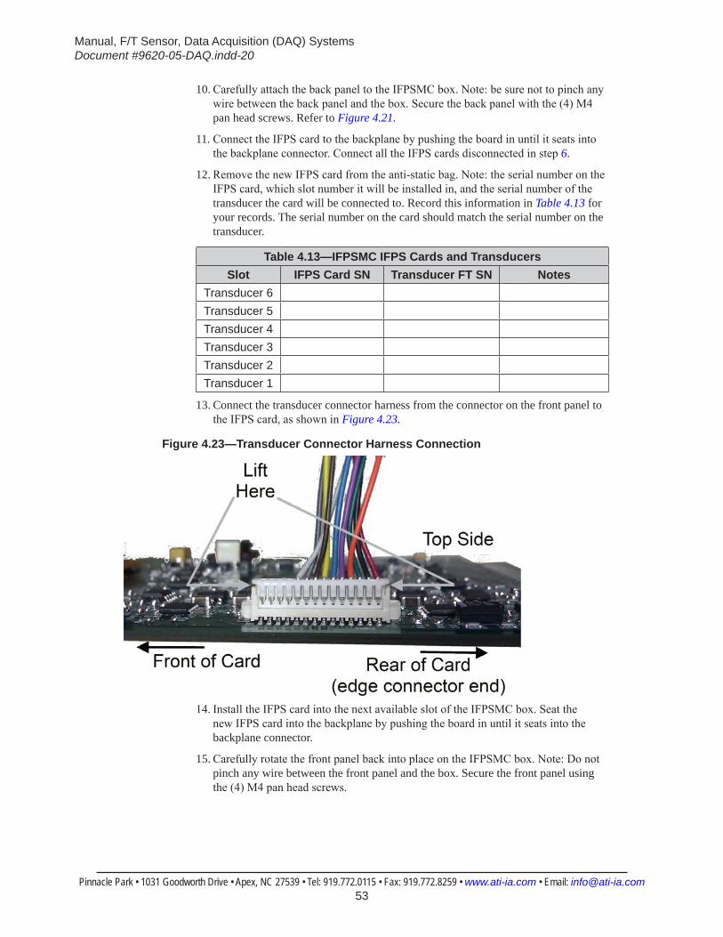
Manual, F/T Sensor, Data Acquisition (DAQ) SystemsDocument #9620-05-DAQ.indd-20
Pinnacle Park • 1031 Goodworth Drive • Apex, NC 27539 • Tel: 919.772.0115 • Fax: 919.772.8259 • www.ati-ia.com • Email: [email protected] 53
10. Carefully attach the back panel to the IFPSMC box. Note: be sure not to pinch any wire between the back panel and the box. Secure the back panel with the (4) M4 pan head screws. Refer to Figure 4.21.
11. Connect the IFPS card to the backplane by pushing the board in until it seats into the backplane connector. Connect all the IFPS cards disconnected in step 6.
12. Remove the new IFPS card from the anti-static bag. Note: the serial number on the IFPS card, which slot number it will be installed in, and the serial number of the transducer the card will be connected to. Record this information in Table 4.13 for your records. The serial number on the card should match the serial number on the transducer.
Table 4.13—IFPSMC IFPS Cards and TransducersSlot IFPS Card SN Transducer FT SN Notes
Transducer 6Transducer 5Transducer 4Transducer 3Transducer 2Transducer 1
13. Connect the transducer connector harness from the connector on the front panel to the IFPS card, as shown in Figure 4.23.
Figure 4.23—Transducer Connector Harness Connection
14. Install the IFPS card into the next available slot of the IFPSMC box. Seat the new IFPS card into the backplane by pushing the board in until it seats into the backplane connector.
15. Carefully rotate the front panel back into place on the IFPSMC box. Note: Do not pinch any wire between the front panel and the box. Secure the front panel using the (4) M4 pan head screws.
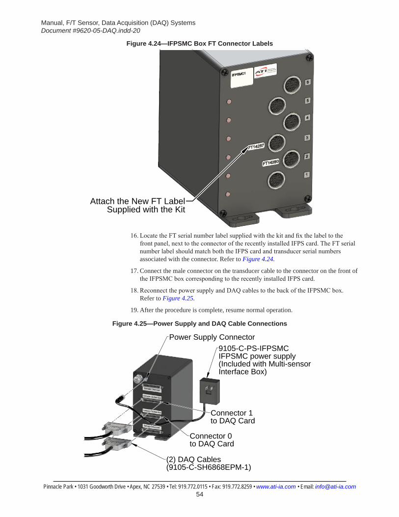
Manual, F/T Sensor, Data Acquisition (DAQ) SystemsDocument #9620-05-DAQ.indd-20
Pinnacle Park • 1031 Goodworth Drive • Apex, NC 27539 • Tel: 919.772.0115 • Fax: 919.772.8259 • www.ati-ia.com • Email: [email protected] 54
Figure 4.24—IFPSMC Box FT Connector Labels
Attach the New FT Label Supplied with the Kit
16. Locate the FT serial number label supplied with the kit and fix the label to the front panel, next to the connector of the recently installed IFPS card. The FT serial number label should match both the IFPS card and transducer serial numbers associated with the connector. Refer to Figure 4.24.
17. Connect the male connector on the transducer cable to the connector on the front of the IFPSMC box corresponding to the recently installed IFPS card.
18. Reconnect the power supply and DAQ cables to the back of the IFPSMC box. Refer to Figure 4.25.
19. After the procedure is complete, resume normal operation.
Figure 4.25—Power Supply and DAQ Cable Connections
Power Supply Connector9105-C-PS-IFPSMC IFPSMC power supply (Included with Multi-sensorInterface Box)
Connector 1 to DAQ Card
Connector 0 to DAQ Card
(2) DAQ Cables(9105-C-SH6868EPM-1)

Manual, F/T Sensor, Data Acquisition (DAQ) SystemsDocument #9620-05-DAQ.indd-20
Pinnacle Park • 1031 Goodworth Drive • Apex, NC 27539 • Tel: 919.772.0115 • Fax: 919.772.8259 • www.ati-ia.com • Email: [email protected] 55
4.5.6.3 PowerThe small connector on the rear of the box is for power input. A Murr 7000-08481-0000000 connector (female) may be used to mate with the power input connector.
Figure 4.26—Power Input Connector
Table 4.14—IFPSMC Power Input Connector Pin AssignmentsPin Description1 +V input3 0V input4 No connection
The IFPSMC accepts from +4.65VDC to +15VDC.
Table 4.15—Typical Input Current at Various Voltages at Room Temperature
ModelCurrent Draw
@ 5VDC @12VDC @15VDC9105-IFPSMC-2 0.36A 0.19A 0.16A9105-IFPSMC-3 0.54A 0.28A 0.24A9105-IFPSMC-4 0.72A 0.37A 0.32A9105-IFPSMC-5 0.90A 0.46A 0.40A9105-IFPSMC-6 1.08A 0.56A 0.48A
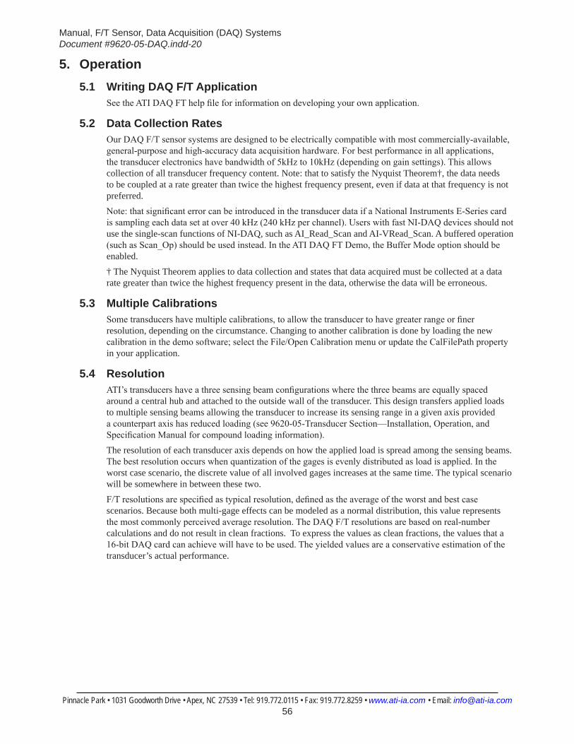
Manual, F/T Sensor, Data Acquisition (DAQ) SystemsDocument #9620-05-DAQ.indd-20
Pinnacle Park • 1031 Goodworth Drive • Apex, NC 27539 • Tel: 919.772.0115 • Fax: 919.772.8259 • www.ati-ia.com • Email: [email protected] 56
5. Operation5.1 Writing DAQ F/T Application
See the ATI DAQ FT help file for information on developing your own application.
5.2 Data Collection RatesOur DAQ F/T sensor systems are designed to be electrically compatible with most commercially-available, general-purpose and high-accuracy data acquisition hardware. For best performance in all applications, the transducer electronics have bandwidth of 5kHz to 10kHz (depending on gain settings). This allows collection of all transducer frequency content. Note: that to satisfy the Nyquist Theorem†, the data needs to be coupled at a rate greater than twice the highest frequency present, even if data at that frequency is not preferred.Note: that significant error can be introduced in the transducer data if a National Instruments E-Series card is sampling each data set at over 40 kHz (240 kHz per channel). Users with fast NI-DAQ devices should not use the single-scan functions of NI-DAQ, such as AI_Read_Scan and AI-VRead_Scan. A buffered operation (such as Scan_Op) should be used instead. In the ATI DAQ FT Demo, the Buffer Mode option should be enabled.† The Nyquist Theorem applies to data collection and states that data acquired must be collected at a data rate greater than twice the highest frequency present in the data, otherwise the data will be erroneous.
5.3 Multiple CalibrationsSome transducers have multiple calibrations, to allow the transducer to have greater range or finer resolution, depending on the circumstance. Changing to another calibration is done by loading the new calibration in the demo software; select the File/Open Calibration menu or update the CalFilePath property in your application.
5.4 ResolutionATI’s transducers have a three sensing beam configurations where the three beams are equally spaced around a central hub and attached to the outside wall of the transducer. This design transfers applied loads to multiple sensing beams allowing the transducer to increase its sensing range in a given axis provided a counterpart axis has reduced loading (see 9620-05-Transducer Section—Installation, Operation, and Specification Manual for compound loading information).The resolution of each transducer axis depends on how the applied load is spread among the sensing beams. The best resolution occurs when quantization of the gages is evenly distributed as load is applied. In the worst case scenario, the discrete value of all involved gages increases at the same time. The typical scenario will be somewhere in between these two.F/T resolutions are specified as typical resolution, defined as the average of the worst and best case scenarios. Because both multi-gage effects can be modeled as a normal distribution, this value represents the most commonly perceived average resolution. The DAQ F/T resolutions are based on real-number calculations and do not result in clean fractions. To express the values as clean fractions, the values that a 16-bit DAQ card can achieve will have to be used. The yielded values are a conservative estimation of the transducer’s actual performance.
Manual, F/T Sensor, Data Acquisition (DAQ) SystemsDocument #9620-05-DAQ.indd-20
Pinnacle Park • 1031 Goodworth Drive • Apex, NC 27539 • Tel: 919.772.0115 • Fax: 919.772.8259 • www.ati-ia.com • Email: [email protected] 57
5.5 EnvironmentalThe standard F/T system is designed to be used in standard laboratory or light-manufacturing conditions. Transducers with an IP60 designation are able to withstand dusty environments. Transducers with an IP65 designation are able to withstand dusty environments and wash down, and those with an IP68 designation are able to withstand dusty environments and freshwater immersion to a specified depth. See ATI Industrial Automation manual (9620-05-Transducer Section—Installation, Operation and Specification Manual) for transducer environmental information. IP60 and non-IP rated transducers, the PS box, and the IFPS box can be used in environments with up to 95% relative humidity, non-condensing.
Table 5.1—Interface Box Temperature RangesModel Storage Operation UnitsPS box -30 to 75 0 to 60 °CIFPS box -30 to 75 0 to 60 °CNote: These temperature ranges specify the storage and operation ranges in which the electronics can
survive without damage. They do not take accuracy into account.
Manual, F/T Sensor, Data Acquisition (DAQ) SystemsDocument #9620-05-DAQ.indd-20
Pinnacle Park • 1031 Goodworth Drive • Apex, NC 27539 • Tel: 919.772.0115 • Fax: 919.772.8259 • www.ati-ia.com • Email: [email protected] 58
6. Maintenance6.1 Periodic Inspection
For most applications, part replacement during normal operation is unnecessary. With industrial-type applications that frequently move the system’s cabling, the cable jacket should be periodically checked for signs of wear. These applications should implement the procedures discussed in Section 7.2—Detecting Failures (Diagnostics) to detect any failures.The transducer must be kept free of excessive dust, debris, or moisture. Applications with metallic debris (i.e., electrically-conductive) must protect the transducer from this debris. Transducers without specific factory-installed protection should be considered unprotected. Should the internal structure of the transducers become clogged with particles, the calibration may be affected or the transducer may be damaged
6.2 Periodic CalibrationPeriodic calibration of the transducer and DAQ card is required to maintain traceability to national standards. Follow any applicable ISO-9000-type standards for calibration. ATI Industrial Automation recommends annual recalibrations, particularly for applications that frequently cycle the loads applied to the transducer.
6.3 Multiple IFPSMC Box RecalibrationThe electronics (IFPS card) in the IFPSMC are needed along with the transducers when the transducers are being recalibrated. Sending the entire IFPSMC box for recalibration along with the transducers is recommended. Occasionally, circumstances require the recalibration of a single transducer, while other transducers remain in use. In this case, remove the transducer’s IFPS card from the IFPSMC box to accompany the transducer for recalibration. Refer to Section 6.3.1—Removing and Replacing the IFPS Card for Recalibration for instructions.
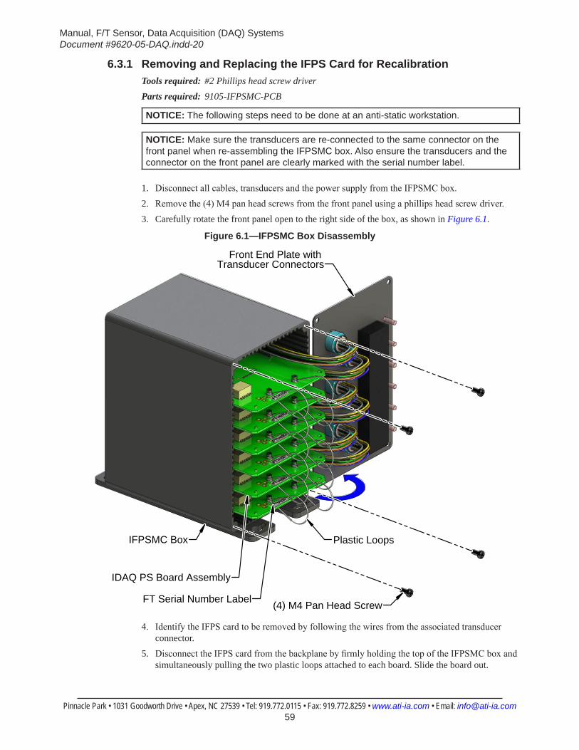
Manual, F/T Sensor, Data Acquisition (DAQ) SystemsDocument #9620-05-DAQ.indd-20
Pinnacle Park • 1031 Goodworth Drive • Apex, NC 27539 • Tel: 919.772.0115 • Fax: 919.772.8259 • www.ati-ia.com • Email: [email protected] 59
6.3.1 Removing and Replacing the IFPS Card for RecalibrationTools required: #2 Phillips head screw driverParts required: 9105-IFPSMC-PCB
NOTICE: The following steps need to be done at an anti-static workstation.
NOTICE: Make sure the transducers are re-connected to the same connector on the front panel when re-assembling the IFPSMC box. Also ensure the transducers and the connector on the front panel are clearly marked with the serial number label.
1. Disconnect all cables, transducers and the power supply from the IFPSMC box. 2. Remove the (4) M4 pan head screws from the front panel using a phillips head screw driver.3. Carefully rotate the front panel open to the right side of the box, as shown in Figure 6.1.
Figure 6.1—IFPSMC Box Disassembly
(4) M4 Pan Head Screw
Front End Plate with Transducer Connectors
IFPSMC Box
IDAQ PS Board Assembly
Plastic Loops
FT Serial Number Label
4. Identify the IFPS card to be removed by following the wires from the associated transducer connector.
5. Disconnect the IFPS card from the backplane by firmly holding the top of the IFPSMC box and simultaneously pulling the two plastic loops attached to each board. Slide the board out.
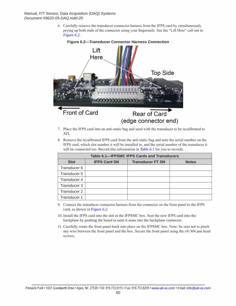
Manual, F/T Sensor, Data Acquisition (DAQ) SystemsDocument #9620-05-DAQ.indd-20
Pinnacle Park • 1031 Goodworth Drive • Apex, NC 27539 • Tel: 919.772.0115 • Fax: 919.772.8259 • www.ati-ia.com • Email: [email protected] 60
6. Carefully remove the transducer connector harness from the IFPS card by simultaneously prying up both ends of the connector using your fingernails. See the “Lift Here” call out in Figure 6.2.
Figure 6.2—Transducer Connector Harness Connection
7. Place the IFPS card into an anti-static bag and send with the transducer to be recalibrated to ATI.
8. Remove the recalibrated IFPS card from the anti-static bag and note the serial number on the IFPS card, which slot number it will be installed in, and the serial number of the transducer it will be connected too. Record this information in Table 6.1 for you to records.
Table 6.1—IFPSMC IFPS Cards and TransducersSlot IFPS Card SN Transducer FT SN Notes
Transducer 6Transducer 5Transducer 4Transducer 3Transducer 2Transducer 1
9. Connect the transducer connector harness from the connector on the front panel to the IFPS card, as shown in Figure 6.2.
10. Install the IFPS card into the slot in the IFPSMC box. Seat the new IFPS card into the backplane by pushing the board in until it seats into the backplane connector.
11. Carefully rotate the front panel back into place on the IFPSMC box. Note: be sure not to pinch any wire between the front panel and the box. Secure the front panel using the (4) M4 pan head screws,

Manual, F/T Sensor, Data Acquisition (DAQ) SystemsDocument #9620-05-DAQ.indd-20
Pinnacle Park • 1031 Goodworth Drive • Apex, NC 27539 • Tel: 919.772.0115 • Fax: 919.772.8259 • www.ati-ia.com • Email: [email protected] 61
Figure 6.3—IFPSMC Box FT Connector Labels
Attach the New FT Label Supplied with the Kit
12. Remove the old FT serial number label from the front panel and fix the FT serial number label supplied with the kit to the front panel for the IFPS card just installed. Refer to Figure 6.3.
13. Connect the male connector on the transducer cable to the appropriate connector on the front of the IFPSMC box. Note: The Serial number label on the Transducer must match the serial number label on the IFPSMC Box connector it is plugged into. Refer to Figure 4.9.
14. Reconnect the power supply and DAQ cables to the back of the IFPSMC box. Refer to Figure 6.4.
15. After the procedure is complete, resume normal operation.
Figure 6.4—Power Supply and DAQ Cable Connections
Power Supply Connector9105-C-PS-IFPSMC IFPSMC power supply (Included with Multi-sensorInterface Box)
Connector 1 to DAQ Card
Connector 0 to DAQ Card
(2) DAQ Cables(9105-C-SH6868EPM-1)
Manual, F/T Sensor, Data Acquisition (DAQ) SystemsDocument #9620-05-DAQ.indd-20
Pinnacle Park • 1031 Goodworth Drive • Apex, NC 27539 • Tel: 919.772.0115 • Fax: 919.772.8259 • www.ati-ia.com • Email: [email protected] 62
7. TroubleshootingThis section includes answers to issues that might arise during the set-up and use of the DAQ system. Each potential question or problem is listed followed by its probable answer or solution; all are categorized for easy reference.
Customer service is available to users who have problems or questions addressed in the manuals.
ATI Industrial Automation Attn: F/T Customer Service Pinnacle Park 1031 Goodworth Drive Apex, NC 27539 USA
Phone: +1.919.772.0115 Fax:+1.919.772.8259 Email: [email protected]
NOTICE: Please read the F/T manuals before calling customer service. When calling, have the following information available:
1. Serial number(s)
2. Transducer type (e.g., Nano17, Gamma, Theta)
3. Calibration (e.g., US-15-50, SI-130-10)
4. An accurate and complete description of the question or problem.
5. If possible, all information displayed on Net F/T page System Info (manuf.htm). The ECATOEM has to be connected to a NetBox to access the System Info.
If possible, the F/T system should be accessible when talking with an ATI Industrial Automation customer service representative.

Manual, F/T Sensor, Data Acquisition (DAQ) SystemsDocument #9620-05-DAQ.indd-20
Pinnacle Park • 1031 Goodworth Drive • Apex, NC 27539 • Tel: 919.772.0115 • Fax: 919.772.8259 • www.ati-ia.com • Email: [email protected] 63
7.1 Errors with Force and Torque ReadingsBad data from the transducer’s strain gages can cause errors in force/torque readings. These errors can result in problems with threshold monitoring, sensor biasing and accuracy. Listed below are basic conditions of bad data. Use this to troubleshoot your problem. In most cases, problems are easier to detect while viewing raw strain gage data.
Table 7.1—Troubleshooting TableSymptom Cause Resolution
Saturation
When the data from a raw decimal strain gage reads the positive or negative maximums, that gage is saturated. Saturation occurs if the sensor is loaded beyond its rated maximum or in the event of an electrical failure within the system.
Stop applying force to the transducer and wait until the error clears to continue. If error does not clear, it may indicate the overload value has been exceeded or a loss of power.
Noise
Excessive noise can be caused by mechanical vibrations and electrical disturbances, possibly from a poor ground. It can also indicate component failure within the system.
Make sure the unit is grounded properly and the area is isolated from electrical disturbances.
Drift
After a load is removed or applied, the raw gage reading does not stabilize but continues to increase or decrease. This may be observed more easily while viewing resolved F/T data. Drift is caused by temperature change, mechanical coupling, or internal failure. Mechanical coupling is caused when a physical connection is made between the tool plate and the sensor body (i.e., plastic filings between the tool adapter plate and the transducer body). Some mechanical coupling is common, such as hoses and wires attached to a tool.
Make sure the tool, tool adapter plate and the transducer body are isolated from each other and no debris lies between the transducer body and tool plate.
Hysteresis
When the sensor is loaded and then unloaded, gage readings do not return quickly and completely to their original readings. Hysteresis is caused by mechanical coupling (explained in drift section) or internal failure.
Make sure the tool, tool adapter plate and the transducer body are isolated from each other and no debris lies between the transducer body and tool plate.
Manual, F/T Sensor, Data Acquisition (DAQ) SystemsDocument #9620-05-DAQ.indd-20
Pinnacle Park • 1031 Goodworth Drive • Apex, NC 27539 • Tel: 919.772.0115 • Fax: 919.772.8259 • www.ati-ia.com • Email: [email protected] 64
7.2 Detecting Failures (Diagnostics)
7.2.1 Detecting Connection IssuesThe F/T system is designed to output voltages that are within the specified output voltage range (±5V or ±10V) as long as the transducer is not being overloaded and is connected to the PS or IFPS box. If the transducer cable is disconnected or has been damaged, the output of the system will be outside the specified output voltage range. By performing periodic checks of the voltages, a failure can be detected. If any of the voltages are at or outside this range, a problem with the transducer or its cabling may exist.
CAUTION: When any strain gage output is saturated or otherwise inoperable, all transducer F/T readings are invalid. Therefore, it is vitally important to monitor for these conditions.
7.2.2 Detecting Cable ProblemsA properly functioning DAQ system will deliver voltages representative of transducer loading from the transducer to the DAQ card inputs. The DAQ system provides two safety features to aid in detection of cabling problems that could disrupt the reading of transducer voltages.
1. If the cable is disconnected between the transducer and its IFPS or PS box, voltages sent to the DAQ card from the box will be forced to a saturation level.
2. The T out signal outputs a voltage that is either -1.54V if no temperature reader circuit is installed, or a voltage greater than +0.5V if the temperature reader is installed and the temperature is above -10oC.
If the acquired transducer voltages are A/D saturated or T out is not between -1.6V to -1.5V, or not between +0.5V and saturation, there may be a cable issue.
7.2.3 Detecting Sensitivity ChangesSensitivity checking of the transducer can be used to measure the transducer system’s health. This is done by applying known loads to the transducer and verifying the system output matches the known loads. For example, a transducer mounted to a robot arm may have an end-effector attached to it:
1. If the end-effector has moving parts, they must be moved in a known position.2. Place the robot arm in an orientation that allows the gravity load from the end-effector to exert
load on any transducer output axes. 3. Record the output readings. 4. Position the robot arm to apply another load, this time causing the outputs to move far from the
earlier readings. 5. Record the second set of output readings. 6. Find the differences from the first and second set of readings and use it as your sensitivity value. Even if the values vary somewhat from sample set to sample set, they can be used to detect gross errors. Either the resolved outputs or the raw transducer voltages may be used (the same must be used for all steps of this process).
Manual, F/T Sensor, Data Acquisition (DAQ) SystemsDocument #9620-05-DAQ.indd-20
Pinnacle Park • 1031 Goodworth Drive • Apex, NC 27539 • Tel: 919.772.0115 • Fax: 919.772.8259 • www.ati-ia.com • Email: [email protected] 65
8. Regulatory InformationThe regulator information applies to the ATI product covered in this manual. Product described from other manufacturers products are excluded. It is the users responsibility to verify product other than ATI product meet the regulatory requirements.
8.1 Electromagnetic CompatibilityThe ATI products meet the requirements for the following EMC standards for electrical equipment for measurement, control, and laboratory use:Emissions:EN61326-1:2013 EN55011:2009 + A1:2010 EN61000-3-2:2006 +A1:2009 +A2:2009, EN61000-3-3:2013 Immunity: EN61326-1:2013 EN61000-4-2:2009, EN61000-4-3:2006 + A2:2010, EN61000-4-4:2012, EN61000-4-5:2006, EN61000-4-6:2009, EN61000-4-8:2010, EN61000-4-11:2004 EN61000-4-8:2010, EN61000-4-11:2004
8.2 RoHS ComplianceThe ATI products conforms to EU Directive CE 2011/65/EU (RoHS).
8.3 Safety StandardsThe ATI products are designed to meet the requirements of the following electrical equipment safety standards for measurement, control, and laboratory use:TBD
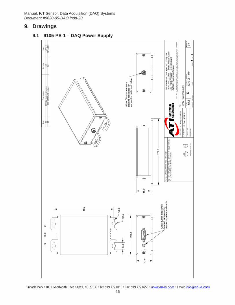
Manual, F/T Sensor, Data Acquisition (DAQ) SystemsDocument #9620-05-DAQ.indd-20
Pinnacle Park • 1031 Goodworth Drive • Apex, NC 27539 • Tel: 919.772.0115 • Fax: 919.772.8259 • www.ati-ia.com • Email: [email protected] 66
9. Drawings9.1 9105-PS-1 – DAQ Power Supply
38.
9
177
.8
Allo
w 6
0mm
cle
aran
cebe
yond
face
plat
e fo
rco
nnec
tor m
ate
and
cabl
e
43.
6
106
.6
Allo
w 8
0mm
cle
aran
cebe
yond
face
plat
e fo
rco
nnec
tor m
ate
and
cabl
e
17.
8 R
4.8 R
2.2
160
58.
9 Re
v.D
escr
iptio
nIn
itiat
orD
ate
02EC
9124
: Upd
ated
Hou
sing
RKC
11/9
/201
103
ECO
1289
4 Ro
HS u
pdat
eEL
B12
/16/
2014
B1:
1.5
11
REVI
SIO
N
NO
TES:
UN
LESS
OTH
ERW
ISE
SPEC
IFIE
D
DO
NO
T SC
ALE
DRA
WIN
G.
DRA
WN
IN S
OLID
WO
RKS.
ALL
DIM
ENSI
ON
S A
RE IN
MILL
IMET
ERS.
3rd
AN
GLE
PRO
JEC
TION
DRA
WN
BY:
CHE
CKE
D B
Y:
WEI
GHT
LBS
:
ASS
EMBL
Y RE
F:
C. S
turg
is 4
/14/
10
D. P
erry
4/1
4/10
TITLE SC
ALE
SIZE
DRA
WIN
G N
UMBE
R
PRO
DUC
T RE
LEA
SE #
SHEE
T
OF
9230
-05-
1370
B1:
1.5
11
-
REVI
SIO
N
03
PRO
PERT
Y O
F A
TI IN
DUS
TRIA
L A
UTO
MA
TION
, IN
C. N
OT
TO B
E RE
PRO
DUC
ED IN
AN
Y M
AN
NER
EXC
EPT
ON
ORD
ER O
R W
ITH P
RIO
R W
RITT
EN A
UTHO
RIZA
TION
OF
ATI.
1031
Goo
dwor
th Dr
ive, A
pex,
NC 27
539,
USA
Tel: +
1.919
.772.0
115
Em
ail: in
fo@ati
-ia.co
mFa
x: +1
.919.7
72.82
59
www
.ati-ia
.com
ISO
9001
Reg
ister
ed C
ompa
ny
DAQ
Pow
er S
uppl
y DA
TE:
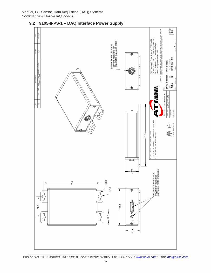
Manual, F/T Sensor, Data Acquisition (DAQ) SystemsDocument #9620-05-DAQ.indd-20
Pinnacle Park • 1031 Goodworth Drive • Apex, NC 27539 • Tel: 919.772.0115 • Fax: 919.772.8259 • www.ati-ia.com • Email: [email protected] 67
9.2 9105-IFPS-1 – DAQ Interface Power Supply
38.
9
177
.8
Allo
w 6
0mm
cle
aran
cebe
yond
face
plat
e fo
rco
nnec
tor m
ate
and
cabl
e 1
06.6
43.
6
Allo
w 8
0mm
cle
aran
cebe
yond
face
plat
e fo
rco
nnec
tor m
ate
and
cabl
e
58.
9
160
17.
8 R
4.8
R2.
2
Rev.
Des
crip
tion
Initi
ator
Dat
e
03Ec
o 11
768;
Mod
el u
pdat
ed, a
dd
ed le
ader
to
conn
ecto
r vie
w.
LJH
4/15
/201
4
B1:
1.5
11
REVI
SIO
N
NO
TES:
UN
LESS
OTH
ERW
ISE
SPEC
IFIE
D
DO
NO
T SC
ALE
DRA
WIN
G.
DRA
WN
IN S
OLID
WO
RKS.
ALL
DIM
ENSI
ON
S A
RE IN
MILL
IMET
ERS.
3rd
AN
GLE
PRO
JEC
TION
DRA
WN
BY:
CHE
CKE
D B
Y:
WEI
GHT
LBS
:
ASS
EMBL
Y RE
F:
C. S
turg
is 4
/14/
10
D. P
erry
4/1
4/10
TITLE SC
ALE
SIZE
DRA
WIN
G N
UMBE
R
PRO
DUC
T RE
LEA
SE #
SHEE
T
OF
9230
-05-
1369
B1:
1.5
11
-
REVI
SIO
N
03
PRO
PERT
Y O
F A
TI IN
DUS
TRIA
L A
UTO
MA
TION
, IN
C. N
OT
TO B
E RE
PRO
DUC
ED IN
AN
Y M
AN
NER
EXC
EPT
ON
ORD
ER O
R W
ITH P
RIO
R W
RITT
EN A
UTHO
RIZA
TION
OF
ATI.
1031
Goo
dwor
th Dr
ive, A
pex,
NC 27
539,
USA
Tel: +
1.919
.772.0
115
Em
ail: in
fo@ati
-ia.co
mFa
x: +1
.919.7
72.82
59
www
.ati-ia
.com
ISO
9001
Reg
ister
ed C
ompa
ny
DAQ
Inte
rface
Pow
er S
uppl
y
DA
TE:
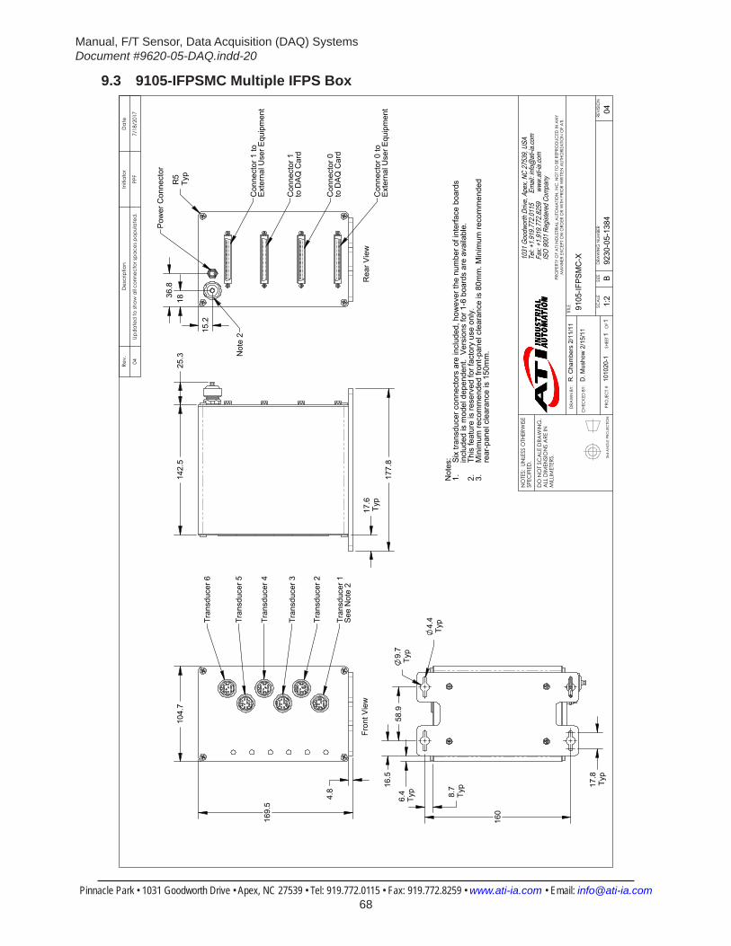
Manual, F/T Sensor, Data Acquisition (DAQ) SystemsDocument #9620-05-DAQ.indd-20
Pinnacle Park • 1031 Goodworth Drive • Apex, NC 27539 • Tel: 919.772.0115 • Fax: 919.772.8259 • www.ati-ia.com • Email: [email protected] 68
9.3 9105-IFPSMC Multiple IFPS Box
3rd
AN
GLE
PRO
JEC
TION
169.
5
104.
7
4.8
Tran
sduc
er 2
Tran
sduc
er 3
Tran
sduc
er 6
Tran
sduc
er 1
See
Not
e 2
Tran
sduc
er 5
Tran
sduc
er 4
Fron
t Vie
w
142.
525
.3
177.
8
17.6
Typ
160
58.9
9.7
Typ
16.5
4.4
Typ
17.8
Typ
8.7
Typ
6.4
Typ
1836.8
15.2
R5
Typ
Pow
er C
onne
ctor
Con
nect
or 1
toE
xter
nal U
ser E
quip
men
t
Con
nect
or 0
toE
xter
nal U
ser E
quip
men
t
Con
nect
or 0
to
DA
Q C
ard
Con
nect
or 1
to
DA
Q C
ard
Rea
r Vie
w
Not
e 2
Not
es: Six
tran
sduc
er c
onne
ctor
s ar
e in
clud
ed, h
owev
er th
e nu
mbe
r of i
nter
face
boa
rds
1.in
clud
ed is
mod
el d
epen
dent
. V
ersi
ons
for 1
-6 b
oard
s ar
e av
aila
ble.
This
feat
ure
is re
serv
ed fo
r fac
tory
use
onl
y.2.
Min
imum
reco
mm
ende
d fro
nt-p
anel
cle
aran
ce is
80m
m. M
inim
um re
com
men
ded
3.re
ar-p
anel
cle
aran
ce is
150
mm
.
Rev.
Des
crip
tion
Initi
ator
Dat
e
04Up
dat
ed to
show
all c
onne
ctor
spac
es p
opul
ated
.PP
F7/
18/2
017
B1:
21
1RE
VISI
ON
NO
TES:
UN
LESS
OTH
ERW
ISE
SPEC
IFIE
D.
DO
NO
T SC
ALE
DRA
WIN
G.
ALL
DIM
ENSI
ON
S A
RE IN
M
ILLIM
ETER
S.
DRA
WN
BY:
CHE
CKE
D B
Y:
R. C
ham
bers
2/1
1/11
D. M
usho
w 2
/15/
11
TITLE SC
ALE
SIZE
DRA
WIN
G N
UMBE
R
PRO
JEC
T #
SHEE
T
O
F 92
30-0
5-13
8410
1020
-104
PRO
PERT
Y O
F A
TI IN
DUS
TRIA
L A
UTO
MA
TION
, IN
C. N
OT
TO B
E RE
PRO
DUC
ED IN
AN
Y M
AN
NER
EXC
EPT
ON
ORD
ER O
R W
ITH P
RIO
R W
RITT
EN A
UTHO
RIZA
TION
OF
ATI.
1031
Goo
dwor
th Dr
ive, A
pex,
NC 27
539,
USA
Tel: +
1.919
.772.0
115
Em
ail: in
fo@ati
-ia.co
mFa
x: +1
.919.7
72.82
59
www
.ati-ia
.com
ISO
9001
Reg
ister
ed C
ompa
ny
9105
-IFPS
MC
-X

Manual, F/T Sensor, Data Acquisition (DAQ) SystemsDocument #9620-05-DAQ.indd-20
Pinnacle Park • 1031 Goodworth Drive • Apex, NC 27539 • Tel: 919.772.0115 • Fax: 919.772.8259 • www.ati-ia.com • Email: [email protected] 69
10. Terms and Conditions of SaleThe following Terms and Conditions are a supplement to and include a portion of ATI’s Standard Terms and Conditions, which are on file at ATI and available upon request.
ATI warrants to Purchaser that force torque sensor products purchased hereunder will be free from defects in material and workmanship under normal use for a period of one year from the date of shipment. This warranty does not cover components subject to wear and tear under normal usage or those requiring periodic replacement. ATI will have no liability under this warranty unless: (a) ATI is given written notice of the claimed defect and a description thereof with thirty (30) days after Purchaser discovers the defect and in any event, not later than the last day of the warranty period and (b) the defective item is received by ATI not later than (10) days after the last day of the warranty period. ATI’s entire liability and Purchaser’s sole remedy under this warranty is limited to repair or replacement, at ATI’s election, of the defective part or item or, at ATI’s election, refund of the price paid for the item. The foregoing warranty does not apply to any defect or failure resulting from improper installation, operation, maintenance, or repair by anyone other than ATI.
ATI will in no event be liable for incidental, consequential, or special damages of any kind, even if ATI has been advised of the possibility of such damages. ATI’s aggregate liability will in no event exceed the amount paid by the purchaser for the item which is the subject of claim or dispute. ATI will have no liability of any kind for failure of any equipment or other items not supplied by ATI.
No action against ATI, regardless of form, arising out of or in any way connected with products or services supplied hereunder, may be brought more than one year after the cause of action accrued.
No representation or agreement varying or extending the warranty and limitation of remedy provisions contained herein is authorized by ATI, and may not be relied upon as having been authorized by ATI, unless in writing and signed by an executive officer of ATI.
Unless otherwise agreed in writing by ATI, all designs, drawings, data, inventions, software, and other technology made or developed by ATI in the course of providing products and services hereunder, and all rights therein under any patent, copyright, or other law protecting intellectual property, shall be and remain ATI’s property. The sale of products or services hereunder does not convey any expressed or implied license under any patent, copyright, or other intellectual property right owned or controlled by ATI, whether relating to the products sold or any other matter, except for the license expressly granted below.
In the course of supplying products and services hereunder, ATI may provide or disclose to Purchaser confidential and proprietary information of ATI relating to the design, operation, or other aspects of ATI’s products. As between ATI and Purchaser, ownership of such information, including without limitation any computer software provided to Purchaser by ATI, shall remain in ATI and such information is licensed to Purchaser only for Purchaser’s use in operating the products supplied by ATI hereunder in Purchaser’s internal business operations.
Without ATI’s prior written permission, Purchaser will not use such information for any other purpose of provide or otherwise make such information available to any third party. Purchaser agrees to take all reasonable precautions to prevent any unauthorized use or disclosure of such information.
Purchaser will not be liable hereunder with respect to disclosure or use of information which: (a) is in the public domain when received from ATI, (b) is thereafter published or otherwise enters the public domain through no fault of Purchaser, (c) is in Purchaser’s possession prior to receipt from ATI, (d) is lawfully obtained by Purchaser from a third party entitled to disclose it, or (f) is required to be disclosed by judicial order or other governmental authority, provided that, with respect to such to maintain the confidentiality of such information.
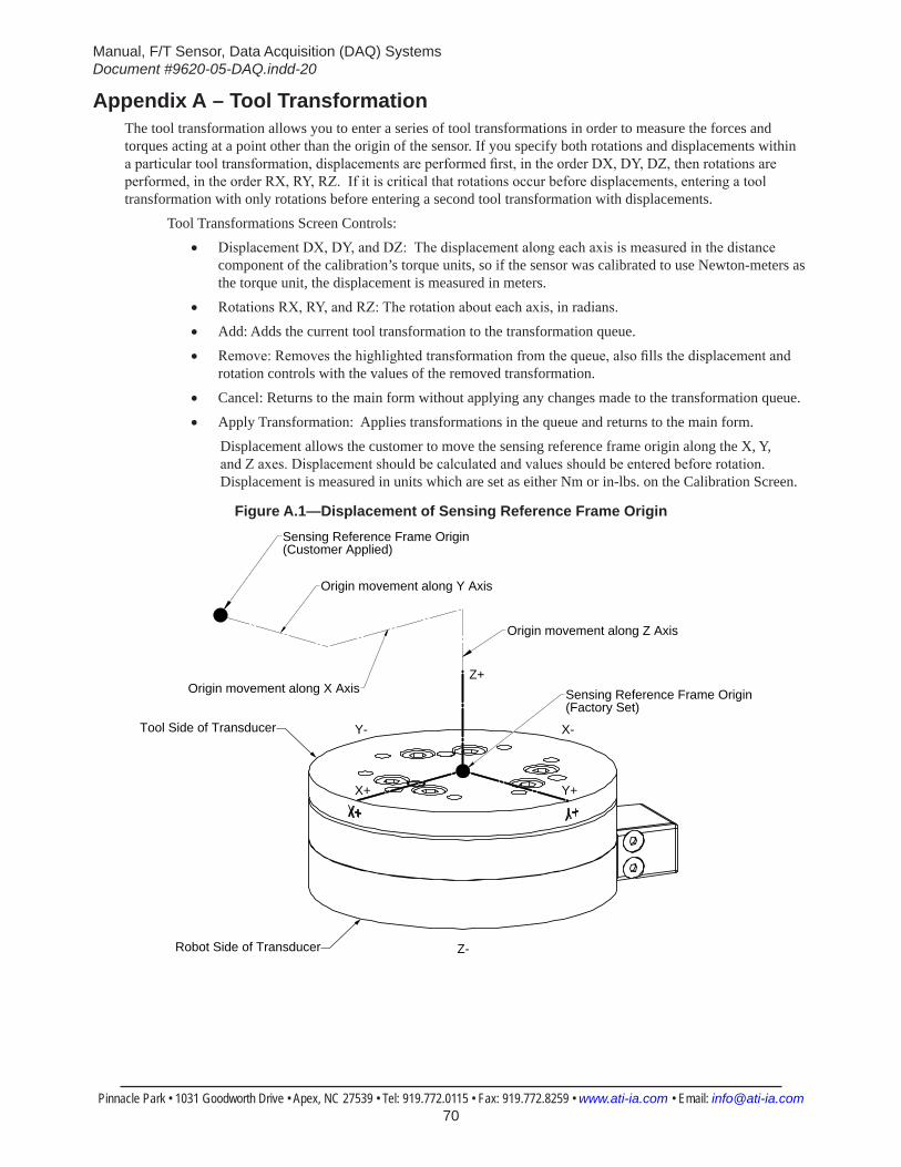
Manual, F/T Sensor, Data Acquisition (DAQ) SystemsDocument #9620-05-DAQ.indd-20
Pinnacle Park • 1031 Goodworth Drive • Apex, NC 27539 • Tel: 919.772.0115 • Fax: 919.772.8259 • www.ati-ia.com • Email: [email protected] 70
Appendix A – Tool TransformationThe tool transformation allows you to enter a series of tool transformations in order to measure the forces and torques acting at a point other than the origin of the sensor. If you specify both rotations and displacements within a particular tool transformation, displacements are performed first, in the order DX, DY, DZ, then rotations are performed, in the order RX, RY, RZ. If it is critical that rotations occur before displacements, entering a tool transformation with only rotations before entering a second tool transformation with displacements.
Tool Transformations Screen Controls:• Displacement DX, DY, and DZ: The displacement along each axis is measured in the distance
component of the calibration’s torque units, so if the sensor was calibrated to use Newton-meters as the torque unit, the displacement is measured in meters.
• Rotations RX, RY, and RZ: The rotation about each axis, in radians.
• Add: Adds the current tool transformation to the transformation queue.
• Remove: Removes the highlighted transformation from the queue, also fills the displacement and rotation controls with the values of the removed transformation.
• Cancel: Returns to the main form without applying any changes made to the transformation queue.
• Apply Transformation: Applies transformations in the queue and returns to the main form.Displacement allows the customer to move the sensing reference frame origin along the X, Y, and Z axes. Displacement should be calculated and values should be entered before rotation. Displacement is measured in units which are set as either Nm or in-lbs. on the Calibration Screen.
Figure A.1—Displacement of Sensing Reference Frame Origin
Z+Sensing Reference Frame Origin(Factory Set)
Sensing Reference Frame Origin(Customer Applied)
Origin movement along X Axis
Origin movement along Y Axis
Origin movement along Z Axis
X+ Y+
X-Y-
Z-
Tool Side of Transducer
Robot Side of Transducer

Manual, F/T Sensor, Data Acquisition (DAQ) SystemsDocument #9620-05-DAQ.indd-20
Pinnacle Park • 1031 Goodworth Drive • Apex, NC 27539 • Tel: 919.772.0115 • Fax: 919.772.8259 • www.ati-ia.com • Email: [email protected] 71
Rotation allows the customer to rotate the axes while maintaining the frame origin. Figure A.2 shows the direction of rotation about the axis. Rotation is measured in radians.When a value is entered for RX, RY, or RZ the following will result:• RX value will rotate Y and Z about X in the direction shown (see Figure A.2).• RY value will rotate X and Z about Y in the direction shown.• RZ value will rotate X and Y about Z in the direction shown.In a tool transformation, the order of the rotations is critical. The X-rotation occurs first, followed by rotation about Y (in its new orientation), then Z. Therefore, rotations MUST be expressed in this order
Figure A.2—Rotating Reference Frame
Z+
X+ Y+
X-Y-
Z-
X+ This example showsa rotation of 1.571 radiansof the X axis.
Y+ Axisafter X Rotation
Z+ Axisafter X Rotation
Sensing Reference Frame Origin(Customer Applied)
Sensing Reference Frame Origin(Factory Set)
Tool Side of Transducer
Robot Side of Transducer