ft81x creating a simple library for pic mcu · the hardware used for developing this code is based...
TRANSCRIPT

Use of Bridgetek devices in life support and/or safety applications is entirely at the user’s risk, and the user agrees to defend, indemnify and hold Bridgetek harmless from any and all damages,
claims, suits or expense resulting from such use.
Bridgetek Pte Ltd (BRTChip) 178 Paya Lebar Road, #07-03, Singapore 409030
Tel: +65 6547 4827 Fax: +65 6841 6071
Web Site: http://www.brtchip.com Copyright © Bridgetek Pte Ltd
Application Note
BRT_AN_008
FT81x Creating a Simple Library
For PIC MCU
Version 1.1
Issue Date: 2018-03-27
This application note provides an example of creating a simple library for interfacing the FT81X device to a PIC MCU. It builds on the framework provided in BRT_AN_006, with the addition of a new API layer to support instructions in a similar format to the FT81X Programmers guide. The library consists of a series of C and header files and can be ported to other MCUs and host platforms which have an SPI Master.

2 Product Page
Document Feedback Copyright © Bridgetek Pte Ltd
Application Note
BRT_AN_008 FT81x Creating a Simple Library For PIC MCU Version 1.1
Document No.: BRT_000084 Clearance No.: BRT#085
Table of Contents
1 Introduction .............................................................. 4
1.1 Overview ............................................................................. 4
1.2 Scope .................................................................................. 4
1.3 Compatibility ....................................................................... 4
2 Hardware ................................................................... 5
3 Library Architecture ................................................... 6
3.1 Layers ................................................................................. 6
3.2 Folder Structure .................................................................. 7
3.3 Header Files ........................................................................ 7
3.4 FT81X and FT80X ................................................................ 8
4 Usage Examples ........................................................ 9
5 Main Application ...................................................... 13
5.1 Overview ........................................................................... 13
5.2 APP_Init() ......................................................................... 13
5.3 APP_FlashingDot() ............................................................ 14
6 Library - API Layer .................................................. 16
6.1 Functions........................................................................... 16
6.2 Co-Processor Lists ............................................................. 16
6.3 Writing Data ...................................................................... 17
6.4 GPU Instructions ............................................................... 20
6.5 Co-Processor Commands ................................................... 20
6.6 GPU Instructions (FT81X) ................................................. 20
6.7 Co-Processor Commands (FT81X) ..................................... 21
7 Software - EVE Layer ............................................... 22
7.1 Functions........................................................................... 22
7.2 Addressing Functions ........................................................ 23

3 Product Page
Document Feedback Copyright © Bridgetek Pte Ltd
Application Note
BRT_AN_008 FT81x Creating a Simple Library For PIC MCU Version 1.1
Document No.: BRT_000084 Clearance No.: BRT#085
7.3 Data Functions .................................................................. 23
7.4 Combined Address and Data functions .............................. 24
7.5 Host Command .................................................................. 24
7.6 Co-Processor FIFO Supporting Functions .......................... 25
8 Software - MCU Layer .............................................. 26
8.1 Functions........................................................................... 26
8.2 Data Types ........................................................................ 26
8.3 Initialisation ...................................................................... 27
8.4 GPIO Functions ................................................................. 27
8.5 SPI Functions .................................................................... 27
8.6 Delay Functions ................................................................. 27
8.7 UART Functions ................................................................. 28
9 Using the Code Project ............................................ 29
10 Conclusion ............................................................. 30
11 Contact Information .............................................. 31
Appendix A– References .............................................. 32
Document References ............................................................... 32
Acronyms and Abbreviations ..................................................... 32
Appendix B– List of GPU and Co-Processor Commands 33
GPU Instructions ....................................................................... 33
Co-Processor Commands .......................................................... 33
GPU Instructions (FT81X) ......................................................... 34
Co-Processor Commands (FT81X) ............................................. 35
Appendix C – List of Tables & Figures .......................... 36
List of Figures ........................................................................... 36
List of Tables ............................................................................. 36
Appendix D– Revision History ...................................... 37

4 Product Page
Document Feedback Copyright © Bridgetek Pte Ltd
Application Note
BRT_AN_008 FT81x Creating a Simple Library For PIC MCU Version 1.1
Document No.: BRT_000084 Clearance No.: BRT#085
1 Introduction
1.1 Overview
This application note provides an example of creating a simple library for interfacing the FT81X
device to a PIC MCU. It builds on the framework provided in BRT_AN_006, with the addition of a
new API layer to support instructions in a similar format to the FT81X Programmers guide and the
EVE Screen Editor. The library consists of a series of C and header files and can be ported to other
MCUs and host platforms which have an SPI Master.
1.2 Scope
This application note is a guide to the functions provided in each layer of the library. The library is
intended as a starting point for users to develop further to meet the needs of their application. All
of the code is provided allowing each layer to be customised.
The main.c file can be edited to produce the final application, calling the functions from the
underlying layers. If porting to another MCU platform, the code in MCU_Layer.c can be changed to
match the peripheral API of the chosen controller.
For further background on how the FT8XX’s API and SPI data formatting are implemented in the
code, please refer to BRT_AN_006. It is recommended that the reader be familiar with the
concepts discussed in BRT_AN_006 before using, porting or further developing this library.
1.3 Compatibility
The code provided is primarily targeted at the FT81X series of devices but can also be run on the
FT80X series as they have similar APIs. The start-up code within APP_EVE_Init has some small
differences defined for the FT80X series. Note that FT81X has some new commands and features
not present on the FT80X series. Application note AN_320 is also available for the FT80X series.
This library is written for the PIC family of MCUs (using the PIC18F46K22 in this particular
example) using MPLABX IDE and a PICKit3 debugger. It can be ported both to other PIC devices
and to other MCU types without major modification. The main tasks would be to import the C
source and header files into the project of the target MCU and to edit the MCU layer code so that it
interacts with the correct registers on the chosen MCU.
Other FT8XX libraries and examples are available for other platforms such as FT900 MCU and
Visual Studio on the EVE Examples page.
Note: This code is intended to act as a starting point for developers to create their own libraries
rather than being a complete library package. It is necessary that developers of the final
application incorporating this library review all layers of the code as part of their product
validation. By using any part of this code, the customer agrees to accept full responsibility for
ensuring that their final product operates correctly and complies with any safety requirements, and
accepts full responsibility for any consequences resulting from its use.
5 Product Page
Document Feedback Copyright © Bridgetek Pte Ltd
Application Note
BRT_AN_008 FT81x Creating a Simple Library For PIC MCU Version 1.1
Document No.: BRT_000084 Clearance No.: BRT#085
2 Hardware
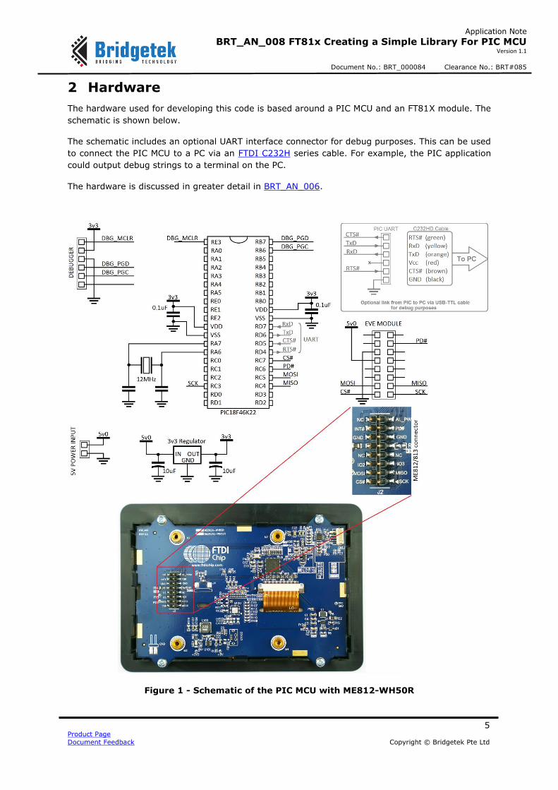
The hardware used for developing this code is based around a PIC MCU and an FT81X module. The
schematic is shown below.
The schematic includes an optional UART interface connector for debug purposes. This can be used
to connect the PIC MCU to a PC via an FTDI C232H series cable. For example, the PIC application
could output debug strings to a terminal on the PC.
The hardware is discussed in greater detail in BRT_AN_006.
Figure 1 - Schematic of the PIC MCU with ME812-WH50R

6 Product Page
Document Feedback Copyright © Bridgetek Pte Ltd
Application Note
BRT_AN_008 FT81x Creating a Simple Library For PIC MCU Version 1.1
Document No.: BRT_000084 Clearance No.: BRT#085
3 Library Architecture
3.1 Layers
Application Layer
This layer implements the main application. It contains the code for initialising the display and then building up each application screen by creating co-processor lists. It will also include header
files where required for image and font data.
This code can be edited to create the screen content required by the final application.
API Layer
This layer is designed to allow the main application to use syntax close to that of the FT81X
Programmers Guide and make it more user friendly.
The functions provided in this layer handle co-processor operation and assist with creating and executing co-processor lists as well as keeping track of the offset within the FIFO for each
command and sending parameters of commands such as text strings.
It also provides functions for loading data into RAM_G and to the RAM_CMD which are required
when loading assets such as bitmaps, compressed images and custom font data.
EVE Layer
This layer translates the calls from the layers above into a series of SPI byte transfers formatted for the protocol used by the FT8XX.
It includes a series of functions which send the register address as well as for reading and writing
8/16/32-bit values. It also has functions for checking the read and write pointers of the RAM_CMD FIFO and for checking the free space available, which are used by the layers above.
MCU Layer
This layer provides an interface to the MCU hardware. It takes the SPI transfers from the EVE layer and translates them into the register level operations needed to control the MCU’s SPI Master
peripheral as well as GPIO operations for chip select and power down.
If porting the provided code to another type of MCU or other SPI host platform, the code in this layer would be modified to suit the register map of the intended SPI Master whilst keeping the
same syntax for calls to this layer from the EVE layer above.
Figure 2 - Layers of the Software Example

7 Product Page
Document Feedback Copyright © Bridgetek Pte Ltd
Application Note
BRT_AN_008 FT81x Creating a Simple Library For PIC MCU Version 1.1
Document No.: BRT_000084 Clearance No.: BRT#085
3.2 Folder Structure
The project provided contains the following files in addition to any MPLAB-specific files:
Source Files
Main.c Contains the Application layer
API_Layer.c Contains the API Layer
EVE_Layer.c Contains the EVE layer
MCU_Layer.c Contains the MCU layer
Header Files
Library.h Contains function definitions etc. for the MCU/EVE/API layers
FT8xx.h Contains the EVE register defines and bit-shifting functions to combine
commands with parameters. It has defines for both FT80x and FT81x and
so FT_81X_ENABLE must be defined for this demonstration.
Note: The project is provided with each layer in a different .c file as detailed above, for ease of
readability and when porting to other MCU platforms. However, the content from API_Layer,
EVE_Layer.c and MCU_Layer.c can be combined into the main.c file to make a single source file if
preferred.
3.3 Header Files
The header file FT81x.h was based on the from the main EVE Sample application. This file provides
definitions for the memory map, register names and for the EVE primitives and commands.
In addition, since many EVE commands include not only the command opcode but also some
parameters mapped into a single 32-bit value, the definitions help to make the main application
code more readable.
E.g. the call EVE_Write32 (COLOR_RGB(255,0,0)); is manipulated as follows:
#define COLOR_RGB(red,green,blue)
((4UL<<24) | (((red)&255UL)<<16) | (((green)&255UL)<<8) | (((blue)&255UL)<<0))
This results in a final value of 0x04FF0000 which combines the instruction 0x04 and the red,
green and blue values.

8 Product Page
Document Feedback Copyright © Bridgetek Pte Ltd
Application Note
BRT_AN_008 FT81x Creating a Simple Library For PIC MCU Version 1.1
Document No.: BRT_000084 Clearance No.: BRT#085
3.4 FT81X and FT80X
The code example can be used on the FT81X or the FT80X series. It is provided configured for the
FT81X series but the following modifications can be made to target the FT80x (FT800 or FT801).
There are two changes required which are explained below.
Firstly, in FT8xx.h, comment out the define for the FT81X.
// #ifndef FT_81X_ENABLE //
// #define FT_81X_ENABLE // Comment these 3 lines out if FT800 or FT801
// #endif
- This define is used to select the correct register definitions for the FT80X or FT81X. o When commented out (selecting the FT80X) the defines in the upper half of FT8xx.h
will be enabled. o When enabled (selecting the FT81X) the defines in the lower half of FT8xx.h will be
enabled.
- It also enables or disables definitions of commands which are for the FT81X only in Library.h and API_Layer.c. When creating a project for the FT80X, please ensure to use only commands from the FT80X Programmers Guide in main.c as the FT81X-specific commands will be unavailable.
- The define also affects the start-up sequence in main.c. Additional host commands are sent
only when the FT80X is selected.
#ifndef FT_81X_ENABLE
//FT80x_selection
EVE_CmdWrite(0x44, 0x00); // 0x44 = HostCMD_CLKEXT
EVE_CmdWrite(0x62, 0x00); // 0x64 = HostCMD_CLK48M
EVE_CmdWrite(0x68, 0x00); // 0x68 = HostCMD_CORE RESET
#endif
Secondly, adjust the display settings in main.c to suit the selected display. For example, when
using an VM800B, the following values could be used.
lcdWidth = 480; // Active width of LCD display
lcdHeight = 272; // Active height of LCD display
lcdHcycle = 548; // Total number of clocks per line
lcdHoffset = 43; // Start of active line
lcdHsync0 = 0; // Start of horizontal sync pulse
lcdHsync1 = 41; // End of horizontal sync pulse
lcdVcycle = 292; // Total number of lines per screen
lcdVoffset = 12; // Start of active screen
lcdVsync0 = 0; // Start of vertical sync pulse
lcdVsync1 = 10; // End of vertical sync pulse
lcdPclk = 5; // Pixel Clock
lcdSwizzle = 0; // Define RGB output pins
lcdPclkpol = 1; // Define active edge of PCLK
9 Product Page
Document Feedback Copyright © Bridgetek Pte Ltd
Application Note
BRT_AN_008 FT81x Creating a Simple Library For PIC MCU Version 1.1
Document No.: BRT_000084 Clearance No.: BRT#085
4 Usage Examples
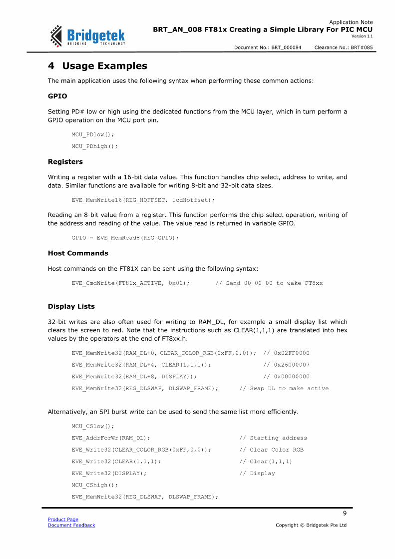
The main application uses the following syntax when performing these common actions:
GPIO
Setting PD# low or high using the dedicated functions from the MCU layer, which in turn perform a
GPIO operation on the MCU port pin.
MCU_PDlow();
MCU_PDhigh();
Registers
Writing a register with a 16-bit data value. This function handles chip select, address to write, and
data. Similar functions are available for writing 8-bit and 32-bit data sizes.
EVE_MemWrite16(REG_HOFFSET, lcdHoffset);
Reading an 8-bit value from a register. This function performs the chip select operation, writing of
the address and reading of the value. The value read is returned in variable GPIO.
GPIO = EVE_MemRead8(REG_GPIO);
Host Commands
Host commands on the FT81X can be sent using the following syntax:
EVE_CmdWrite(FT81x_ACTIVE, 0x00); // Send 00 00 00 to wake FT8xx
Display Lists
32-bit writes are also often used for writing to RAM_DL, for example a small display list which
clears the screen to red. Note that the instructions such as CLEAR(1,1,1) are translated into hex
values by the operators at the end of FT8xx.h.
EVE_MemWrite32(RAM_DL+0, CLEAR_COLOR_RGB(0xFF,0,0)); // 0x02FF0000
EVE_MemWrite32(RAM_DL+4, CLEAR(1,1,1)); // 0x26000007
EVE_MemWrite32(RAM_DL+8, DISPLAY)); // 0x00000000
EVE_MemWrite32(REG_DLSWAP, DLSWAP_FRAME); // Swap DL to make active
Alternatively, an SPI burst write can be used to send the same list more efficiently.
MCU_CSlow();
EVE_AddrForWr(RAM_DL); // Starting address
EVE_Write32(CLEAR_COLOR_RGB(0xFF,0,0)); // Clear Color RGB
EVE_Write32(CLEAR(1,1,1); // Clear(1,1,1)
EVE_Write32(DISPLAY); // Display
MCU_CShigh();
EVE_MemWrite32(REG_DLSWAP, DLSWAP_FRAME);
10 Product Page
Document Feedback Copyright © Bridgetek Pte Ltd
Application Note
BRT_AN_008 FT81x Creating a Simple Library For PIC MCU Version 1.1
Document No.: BRT_000084 Clearance No.: BRT#085
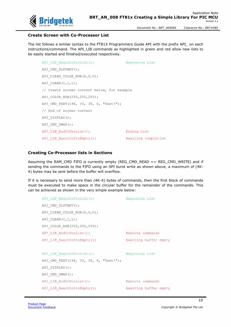
Create Screen with Co-Processor List
The list follows a similar syntax to the FT81X Programmers Guide API with the prefix API_ on each
instructions/command. The API_LIB commands as highlighted in green and red allow new lists to
be easily started and finished/executed respectively.
API_LIB_BeginCoProList(); Beginning List
API_CMD_DLSTART();
API_CLEAR_COLOR_RGB(0,0,0);
API_CLEAR(1,1,1);
// Create screen content below, for example
API_COLOR_RGB(255,255,255);
API_CMD_TEXT(196, 33, 30, 0, "Text!");
// End of screen content
API_DISPLAY();
API_CMD_SWAP();
API_LIB_EndCoProList(); Ending List
API_LIB_AwaitCoProEmpty(); Awaiting completion
Creating Co-Processor lists in Sections
Assuming the RAM_CMD FIFO is currently empty (REG_CMD_READ == REG_CMD_WRITE) and if
sending the commands to the FIFO using an SPI burst write as shown above, a maximum of (4K-
4) bytes may be sent before the buffer will overflow.
If it is necessary to send more than (4K-4) bytes of commands, then the first block of commands
must be executed to make space in the circular buffer for the remainder of the commands. This
can be achieved as shown in the very simple example below:
API_LIB_BeginCoProList(); Beginning List
API_CMD_DLSTART();
API_CLEAR_COLOR_RGB(0,0,0);
API_CLEAR(1,1,1);
API_COLOR_RGB(255,255,255);
API_LIB_EndCoProList(); Execute commands
API_LIB_AwaitCoProEmpty(); Awaiting buffer empty
API_LIB_BeginCoProList(); Beginning List
API_CMD_TEXT(196, 33, 30, 0, "Text!");
API_DISPLAY();
API_CMD_SWAP();
API_LIB_EndCoProList(); Execute commands
API_LIB_AwaitCoProEmpty(); Awaiting buffer empty

11 Product Page
Document Feedback Copyright © Bridgetek Pte Ltd
Application Note
BRT_AN_008 FT81x Creating a Simple Library For PIC MCU Version 1.1
Document No.: BRT_000084 Clearance No.: BRT#085
The overall list of commands in the black text is the same as the example shown in section Create
Screen with Co-Processor List. In particular there is only one occurrence of CMD_DLSTART which
will tell the co-processor to start a new Display List at RAM_DL + 0.
From the co-processor point of view, the overall code here performs exactly the same operation as
the code in section Create Screen with Co-Processor List. Because the second section does not
begin with CMD_DLSTART, the display list entries in RAM_DL resulting from the second set of
commands will be appended to those from the first set of commands.
The list of commands may be split in this way into a number of sections each containing one or
more complete commands. Each block shown in black text may be up to (4K-4) bytes in size.
Note that the library could also be modified to check for free space (as determined by the
difference in REG_CMD_READ and REG_CMD_WRITE) instead of waiting for the co-processor to be
empty (REG_CMD_READ == REG_CMD_WRITE) and the next block of commands could be sent
when there is sufficient free space.
Note: It is important to note that the overall resuting display list generated by these commands in
RAM_DL may not exceed the 8K bytes size of RAM_DL. In addition, 8K bytes of commands will not
necessarily generate 8K of RAM_DL entries.
- Some commands are 4 bytes in size when written to RAM_CMD and result in the equivalent 4 bytes being written to RAM_DL. Examples include COLOR_RGB and VERTEX.
- Other commands may result in a greater number of bytes written to RAM_DL compared to
the size of the command itself. For example, CMD_BUTTON.
The commands used in the particular screen being generated will therefore influence the number
of co-processor commands which can be used on a screen before the 8K RAM_DL limit is reached.
During application development, overrun can be determined by a co-processor error condition
(REG_CMD_READ == 0xFFF) and by REG_CMD_DL reaching 8K in value.
In many cases, a single burst write of less than (4K-4) may be sufficient to create the screen.
Applications which use a large number of VERTEX commands as part of primitive shapes, a chart
using a Line Strip, or large number of text strings may require the co-processor list to be split.
Run a Co-Processor command
Some commands can be used individually via the co-processor to configure the FT81X. These use
the same APIs as above to begin the command and execute it. One example is to set the screen orientation to portrait via CMD_SETROTATE.
API_LIB_BeginCoProList(); Beginning List
API_CMD_SETROTATE(2);
API_LIB_EndCoProList(); Ending List
API_LIB_AwaitCoProEmpty(); Awaiting completion
Loading data to RAM_G
The API_LIB_WriteDataRAMG allows an array of data to be written to a sequential block of RAM_G.
This is useful when loading image or font files for example.
12 Product Page
Document Feedback Copyright © Bridgetek Pte Ltd
Application Note
BRT_AN_008 FT81x Creating a Simple Library For PIC MCU Version 1.1
Document No.: BRT_000084 Clearance No.: BRT#085
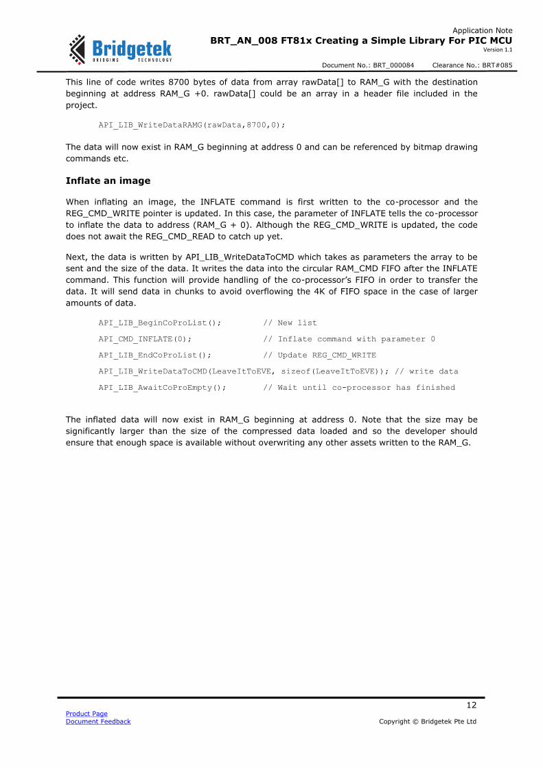
This line of code writes 8700 bytes of data from array rawData[] to RAM_G with the destination
beginning at address RAM_G +0. rawData[] could be an array in a header file included in the
project.
API_LIB_WriteDataRAMG(rawData,8700,0);
The data will now exist in RAM_G beginning at address 0 and can be referenced by bitmap drawing
commands etc.
Inflate an image
When inflating an image, the INFLATE command is first written to the co-processor and the
REG_CMD_WRITE pointer is updated. In this case, the parameter of INFLATE tells the co-processor
to inflate the data to address (RAM_G + 0). Although the REG_CMD_WRITE is updated, the code
does not await the REG_CMD_READ to catch up yet.
Next, the data is written by API_LIB_WriteDataToCMD which takes as parameters the array to be
sent and the size of the data. It writes the data into the circular RAM_CMD FIFO after the INFLATE
command. This function will provide handling of the co-processor’s FIFO in order to transfer the
data. It will send data in chunks to avoid overflowing the 4K of FIFO space in the case of larger
amounts of data.
API_LIB_BeginCoProList(); // New list
API_CMD_INFLATE(0); // Inflate command with parameter 0
API_LIB_EndCoProList(); // Update REG_CMD_WRITE
API_LIB_WriteDataToCMD(LeaveItToEVE, sizeof(LeaveItToEVE)); // write data
API_LIB_AwaitCoProEmpty(); // Wait until co-processor has finished
The inflated data will now exist in RAM_G beginning at address 0. Note that the size may be
significantly larger than the size of the compressed data loaded and so the developer should
ensure that enough space is available without overwriting any other assets written to the RAM_G.

13 Product Page
Document Feedback Copyright © Bridgetek Pte Ltd
Application Note
BRT_AN_008 FT81x Creating a Simple Library For PIC MCU Version 1.1
Document No.: BRT_000084 Clearance No.: BRT#085
5 Main Application
5.1 Overview
This layer is implemented in main.c. In the provided example code, this layer contains an
initialisation section and then calls one of the demo routines.
MCU_Init();
APP_Init();
APP_FlashingDot();
The functions MCU_Init() and APP_Init() initialise the MCU and FT81X respectively, and the code
then remains in the flashing dot application which represents a very basic main application.
MCU_Init is covered under the MCU Layer in section 8.
5.2 APP_Init()
This function performs the application’s configuration of the FT81X including starting up and
writing the display settings registers in the FT81X. It finishes by writing a short display list to clear
the screen.
First, the PD# line is asserted for 20msec and then de-asserted. This resets the FT81X and
provides a clean start-up. The Active host command is then sent to wake up the FT81X. Note that
the external oscillator mode may also be selected via a host command if required at this stage.
Some modules use the internal oscillator and others may have an external crystal.
The FT81X requires a delay of at least 300ms to perform housekeeping actions including
configuring the font/bitmap handles. This delay must be observed to ensure correct operation of
the device. The example code uses a 500ms delay at this point.
After this, a read of the Chip ID register is performed and this must return the expected 0x7C
value before proceeding. Failure to read this value could indicate an issue with the SPI connections
or power to the EVE circuit for example. A read of REG_CPURESET is also performed and must
read value 0x00 before proceeding, which confirms that the FT81X is ready.
The display registers are then written to set the display parameters to match the connected LCD.
The values provided are for 800x480 screens and will work with the ME812-WH50R, ME813-
WH50C and VM810C50A-D modules but can be changed to suit other screens.
The GPIO lines are configured to enable the display, along with the touch threshold for resistive
screens. The audio is not used here and so the volume is turned down. Note that the writing of the
PCLK register and the PWM of the backlight can be done after the first display list to provide a
cleaner start-up appearance to the user.
Finally, a short display list is created which clears the screen. Note that the commands begin at
RAM_DL + 0 and are added to each sequential 4-byte offset. In this case, the Clear Colour RGB
specifies a black colour and then Clear(1,1,1) clears the colour, stencil and tag buffers. The Display
command marks the end of the list, and the Swap will result in this display list becoming active. It
is only after execution of the Swap that any change will be apparent on the screen.
At this point, the SPI clock rate may be increased above 11MHz up to a maximum of 30MHz if
required.

14 Product Page
Document Feedback Copyright © Bridgetek Pte Ltd
Application Note
BRT_AN_008 FT81x Creating a Simple Library For PIC MCU Version 1.1
Document No.: BRT_000084 Clearance No.: BRT#085
5.3 APP_FlashingDot()
This example draws a very simple dot on the screen which alternates in colour between red and
black, thereby appearing to flash red against the black background.
Note that the code here works in exactly the same way as the flashing dot illustrated in
BRT_AN_006 but the main code is simpler due to the addition of the new API layer. The APIs such
as API_LIB_BeginCoProList(); take care of awaiting the co-pro FIFO being empty, sending the
address and handling chip select. Each API_ call which sends a GPU instruction or command takes
care of keeping track of the new offset. This makes programming the screen content much more
user-friendly.
Figure 3 - Flashing Dot Demo
The code runs in a constant while(1) loop. First, a variable is toggled which will be used to
determine the colour of the dot on each screen update.
void APP_FlashingDot(void)
{
uint8_t color = 0;
while(1)
{
if(color == 0x00)
color = 0xFF;
else
color = 0x00;
It then goes on to create the new co-processor list to generate the screen content. The
API_LIB_BeginCoProList function waits for the co-processor FIFO to be empty (whereby the write
and read pointers are equal). The place within the circular co-processor FIFO to which they
currently point is also obtained. It uses this value as the starting point for the new co-processor

15 Product Page
Document Feedback Copyright © Bridgetek Pte Ltd
Application Note
BRT_AN_008 FT81x Creating a Simple Library For PIC MCU Version 1.1
Document No.: BRT_000084 Clearance No.: BRT#085
list. It will assert the CS# line and send the address thereby beginning a burst write cycle to the
CMD_FIFO.
The first command (CMD_DLSTART) will tell the co-processor to make a new display list beginning at offset RAM_DL + 0. The first entries in this list are to set the colour to be used when clearing the screen and to clear the colour, stencil and tag buffers. In most cases, a new co-processor list
will begin in a similar way to the four commands shown. The API_ function call in each case will send the associated command over SPI and will update a variable to keep track of the number of bytes sent.
API_LIB_BeginCoProList();
API_CMD_DLSTART();
API_CLEAR_COLOR_RGB(0,0,0);
API_CLEAR(1,1,1);
Now, the colour of the dot to be drawn is set and a point is drawn on the screen, using standard
commands from the FT81x Programmers Guide.
API_COLOR_RGB(color, 0, 0);
API_BEGIN(FTPOINTS);
API_POINT_SIZE(40*16);
API_VERTEX2F(200*16, 200*16);
API_END();
The co-processor list finishes with a DISPLAY command which, when actioned by the co-processor
and added to the display list, tells the FT8XX that this is the end of the set of display items. The
SWAP command performs the same task as writing to the swap register; once the display list has
been written to the RAM_DL, this command will swap the foreground and background display list
memory so that the newly written display list is now active on the screen.
API_DISPLAY();
API_CMD_SWAP();
The display creation finishes with two API_LIB function calls. The first one will bring CS# high to finish the burst write over SPI and will then perform a write to the REG_CMD_WRITE register to
point it to the end of the new commands added. The call to API_LIB_AwaitCoProEmpty will then wait until the FT81x’s internal REG_CMD_READ pointer has caught up with REG_CMD_WRITE and therefore until the co-processor has consumed all of the commands. API_LIB_EndCoProList();
API_LIB_AwaitCoProEmpty();
Finally, a delay is provided so that the screen refreshes approximately every 500ms and so the flashing of the dot is visible to the user.
MCU_Delay_500ms();
}
}

16 Product Page
Document Feedback Copyright © Bridgetek Pte Ltd
Application Note
BRT_AN_008 FT81x Creating a Simple Library For PIC MCU Version 1.1
Document No.: BRT_000084 Clearance No.: BRT#085
6 Library - API Layer
This layer can be found in API_Layer.c and provides a simpler and higher-level interface between
the main application and the EVE layer.
This layer contains a series of APIs for beginning and finishing co-processor lists which avoid the
main application needing to handle the specifics of the co-processor.
Additional APIs are provided to help with loading data to RAM_G and to the RAM_CMD FIFO, as
well as for sending text strings which are used in several co-processor commands.
The layer also includes a function call for each GPU instruction and Co-Processor command which
can be used when sending these via the co-processor FIFO. This function sends the command and
any parameters and also keeps track of the size of the command which is used to update the
REG_CMD_WRITE when finishing the list.
6.1 Functions
void API_LIB_BeginCoProList(void)
void API_LIB_EndCoProList(void)
void API_LIB_AwaitCoProEmpty(void)
void API_LIB_WriteDataRAMG(const uint8_t *ImgData, uint32_t DataSize, uint32_t
DestAddress)
uint8_t API_SendString(const char* string)
void API_LIB_WriteDataToCMD(const uint8_t *ImgData, uint32_t TotalDataSize)
This layer also includes a separate function for every GPU Instruction and Co-Processor
command as discussed later in this section
6.2 Co-Processor Lists
These functions are used by the main application when creating screens to set up a new co-
processor list and then to execute it.
void API_LIB_BeginCoProList(void)
This function carries out the tasks necessary to create a new co-processor command list. It waits
for the REG_CMD_WRITE and REG_CMD_READ pointers to become equal to confirm that the co-
processor has completed all previous tasks. This also determines the current value of these
pointers to be used as the starting point for the new list.
It then asserts CS# and sends the starting address determined above with the write bits set to tell
the FT81X that data is to be written.
An SPI burst write will continue with the FT81X incrementing its internal address until CS# is de-
asserted.
void API_LIB_EndCoProList(void)

17 Product Page
Document Feedback Copyright © Bridgetek Pte Ltd
Application Note
BRT_AN_008 FT81x Creating a Simple Library For PIC MCU Version 1.1
Document No.: BRT_000084 Clearance No.: BRT#085
This function is used to end a co-processor list. It de-asserts CS# and then writes the value
maintained by the MCU’s own counter into the REG_CMD_WRITE. This causes the co-processor to
execute the commands written in the preceding burst write.
The API functions in the API layer will have updated the aforementioned counter (cmdOffset) as
each command is sent so that the value to be written to REG_CMD_WRITE can be determined.
void API_LIB_AwaitCoProEmpty(void)
This function performs two main tasks. Firstly, it sits in a loop reading the REG_CMD_WRITE and
REG_CMD_READ registers. Then, it reads the current state of REG_CMD_WRITE and updates
global variable cmdOffset so that this variable can be used by the subsequent code as the starting
point for the next co-processor list.
6.3 Writing Data
These functions are used by the main application to perform writing of data blocks to RAM_G and
via the co-processor buffer.
void API_LIB_WriteDataRAMG(const uint8_t *ImgData, uint32_t DataSize,
uint32_t DestAddress)
This function writes a block of 8-bit data from the specified array in the MCU to the FT81X. The
parameters also specify the starting address in RAM_G for the data to be written to and the size of
the data to be written.
Internally, this function uses an SPI burst write whereby the CS# is asserted followed by a write of
the register address to be written in the FT81x. The data can then be written as a burst by keeping
CS# low and the FT81x will increment the address internally. The burst is completed by de-
asserting CS#.
uint8_t API_SendString(const char* string)
This function sends a string over SPI to the FT81X. It is intended to be called from other command
functions such as API_CMD_TEXT where the SPI transfer is already set up and in progress and the
string is part of the parameter set of the function. The API_SendString function does not therefore
carry out addressing or CS# operations.
It works by sending out the string character-by-character as a series of sequential 8-bit SPI writes.
An additional 0x00 byte is sent at the end of the string as a null terminator. Finally, as every
command in EVE must have a multiple of 4 bytes including parameters, the string is padded with
extra 0x00 bytes if it is not an even multiple of 4. This makes the total length including string, null
and padding to a multiple of four bytes to maintain the 32-bit alignment of the co-processor. The
resulting command size is returned to the calling function where it will be added to the size of the
overall command.
void API_LIB_WriteDataToCMD(const uint8_t *ImgData, uint32_t
TotalDataSize)
This function is used to write a block of data to the co-processor FIFO. For example, this would be
used for loading the compressed image data immediately after a CMD_INFLATE or
CMD_LOADIMAGE command.

18 Product Page
Document Feedback Copyright © Bridgetek Pte Ltd
Application Note
BRT_AN_008 FT81x Creating a Simple Library For PIC MCU Version 1.1
Document No.: BRT_000084 Clearance No.: BRT#085
As described in BRT_AN_006, the co-processor uses a 4K circular FIFO with write and read
pointers. The MCU controls the write pointer and the FT8xx controls the read pointer as it removes
data from the FIFO. In most cases, the FIFO is used to send commands which the co-processor
processes to create display lists etc.
However, some commands which inflate compressed data require the image data to be fed into
the co-processor itself which will carry out the inflate operation on the data. This requires more
specific handling compared to writing to RAM_G due to the circular nature and the limited size (4K)
of the buffer.
This function takes care of the buffer handling and also splits the data into smaller chunks if the
overall data size is greater than the buffer. A simplified flow chart is shown in Figure 4.
The function runs in a loop until all requested data has been sent. The data is written to the
RAM_CMD FIFO in the same way as commands, whereby the current write pointer is determined
and the data is written as a burst beginning at that address. The FT8XX increments its internal
counter in parallel with the MCU keeping its own count, both of which also account for the rollover
at RAM_CMD + 4K. The MCU then advances the REG_CMD_WRITE to the end of the newly written
data.
In this example, if the data is greater than 1000 bytes, it is split into chunks of 1000 and will
therefore be written as a series of 1000 bytes bursts followed by the remainder. One difference
occurs here compared to the algorithm normally used when creating a screen. Between sending
1000 byte chunks, the function waits for sufficient free space for the next chunk instead of
awaiting the FIFO being empty (read and write pointers equal). This is because the algorithm used
internally by the co-processor does not always make REG_CMD_READ equal to REG_CMD_WRITE
in the middle of a data set. They will however become equal once the full set of compressed data
has been written.
Note that the size of each chunk can be set as required up to a maximum of (4K-4). However,
increasing the 1000 used in this example would not make a significant difference to efficiency.
19 Product Page
Document Feedback Copyright © Bridgetek Pte Ltd
Application Note
BRT_AN_008 FT81x Creating a Simple Library For PIC MCU Version 1.1
Document No.: BRT_000084 Clearance No.: BRT#085
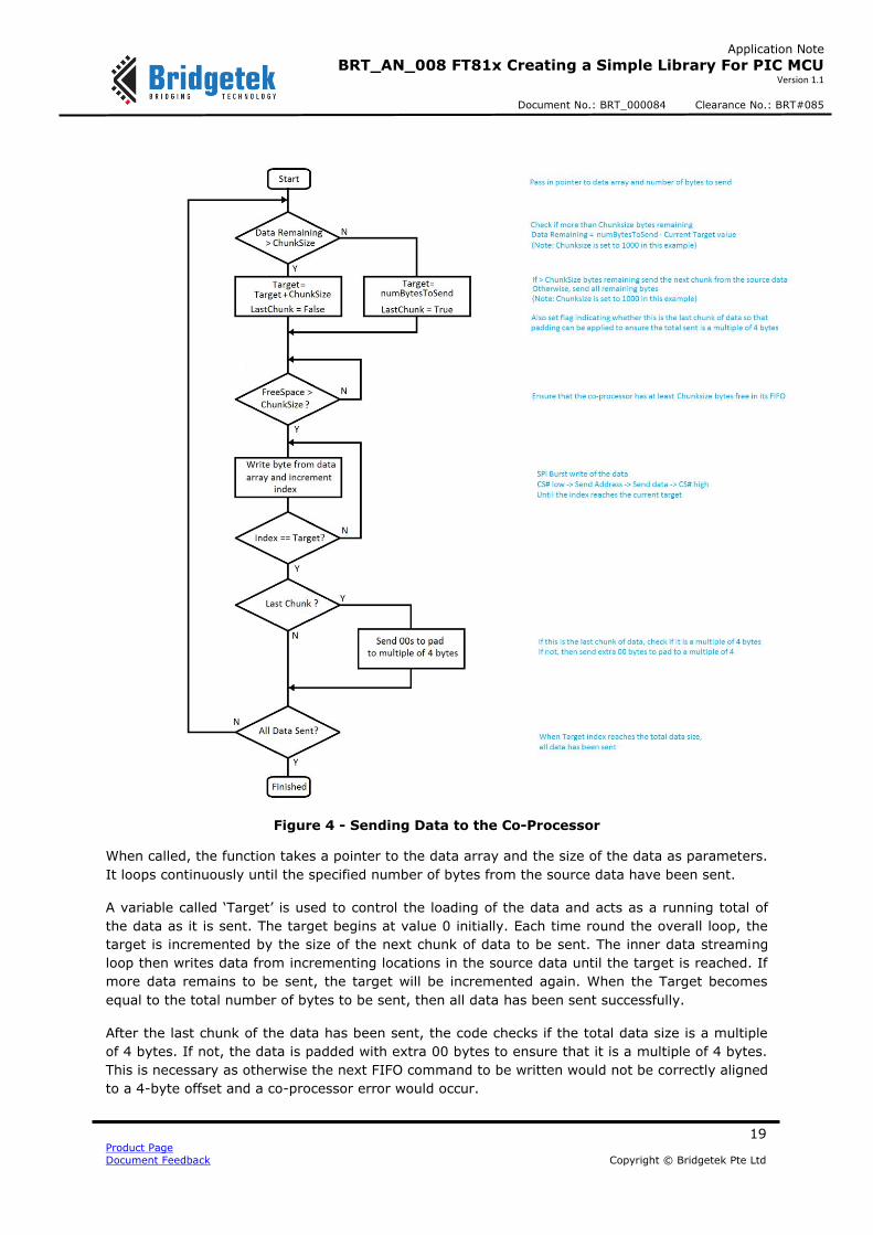
Figure 4 - Sending Data to the Co-Processor
When called, the function takes a pointer to the data array and the size of the data as parameters.
It loops continuously until the specified number of bytes from the source data have been sent.
A variable called ‘Target’ is used to control the loading of the data and acts as a running total of
the data as it is sent. The target begins at value 0 initially. Each time round the overall loop, the
target is incremented by the size of the next chunk of data to be sent. The inner data streaming
loop then writes data from incrementing locations in the source data until the target is reached. If
more data remains to be sent, the target will be incremented again. When the Target becomes
equal to the total number of bytes to be sent, then all data has been sent successfully.
After the last chunk of the data has been sent, the code checks if the total data size is a multiple
of 4 bytes. If not, the data is padded with extra 00 bytes to ensure that it is a multiple of 4 bytes.
This is necessary as otherwise the next FIFO command to be written would not be correctly aligned
to a 4-byte offset and a co-processor error would occur.

20 Product Page
Document Feedback Copyright © Bridgetek Pte Ltd
Application Note
BRT_AN_008 FT81x Creating a Simple Library For PIC MCU Version 1.1
Document No.: BRT_000084 Clearance No.: BRT#085
6.4 GPU Instructions
The GPU instructions can be used either directly by the GPU in a display list or can be passed in via
the co-processor. The latter technique is used in most cases as it allows mixing of GPU and Co-
Processor commands.
An API_ function is provided for each GPU command which allows it to be written to the RAM_CMD
FIFO in the same way as Co-Processor commands and keeps track of the offset in the buffer. e.g.
void API_COLOR_RGB(uint8_t R, uint8_t G, uint8_t B)
{
EVE_Write32(COLOR_RGB(R,G,B));
cmdOffset = EVE_IncCMDOffset(cmdOffset, 4);
}
The function uses the bit shifting operations defined near the bottom of FT8XX.h to format the
parameters into their bit positions in the command. e.g.
#define COLOR_RGB(red,green,blue)
((4UL<<24)|(((red)&255UL)<<16)|(((green)&255UL)<<8)|(((blue)&255UL)<<0))
These functions are listed in Appendix B– List of GPU and Co-Processor Commands
6.5 Co-Processor Commands
Each Co-Processor command has an API_ function in this layer which handles writing of the
command and any parameters. It takes the command in a user-friendly syntax which is compatible
with the FT81X programmers guide and then formats the parameters into the SPI transfers which
the FT81X requires. It also updates the variable which keeps track of the pointer position. E.g.
void API_CMD_NUMBER(int16_t x, int16_t y, int16_t font, uint16_t options, int32_t
n)
{
EVE_Write32(CMD_NUMBER);
EVE_Write32( (((uint32_t)y<<16)|(x & 0xffff)));
EVE_Write32( (((uint32_t)options<<16)|(font&0xffff)));
EVE_Write32( n);
cmdOffset = EVE_IncCMDOffset(cmdOffset, 16);
}
These functions are listed in Appendix B– List of GPU and Co-Processor Commands
6.6 GPU Instructions (FT81X)
These instructions are included in a separate define as they are for the FT81X series only. These
functions are listed along with the other commands in Appendix B– List of GPU and Co-Processor
Commands.

21 Product Page
Document Feedback Copyright © Bridgetek Pte Ltd
Application Note
BRT_AN_008 FT81x Creating a Simple Library For PIC MCU Version 1.1
Document No.: BRT_000084 Clearance No.: BRT#085
6.7 Co-Processor Commands (FT81X)
These commands are included in a separate define as they are for the FT81X series only. These
functions are listed along with the other commands in Appendix B– List of GPU and Co-Processor
Commands.

22 Product Page
Document Feedback Copyright © Bridgetek Pte Ltd
Application Note
BRT_AN_008 FT81x Creating a Simple Library For PIC MCU Version 1.1
Document No.: BRT_000084 Clearance No.: BRT#085
7 Software - EVE Layer
The EVE functions can be found in EVE_Layer.c. They provide the interface between the
Application layer and the MCU layer, allowing the application to use a simpler syntax so that the
developer can focus on the screen content. At the same time, the EVE functions are independent
of MCU type as they use the MCU layer for all MCU-specific accesses.
BRT_AN_006 has further details on how these functions work.
7.1 Functions
void EVE_AddrForWr(uint32_t ftAddress)
void EVE_AddrForRd(uint32_t ftAddress)
void EVE_Write32(uint32_t ftData32)
void EVE_Write16(uint16_t ftData16)
void EVE_Write8(uint8_t ftData8)
uint32_t EVE_Read32(void)
uint16_t EVE_Read16(void)
uint8_t EVE_Read8(void)
void EVE_MemWrite32(uint32_t ftAddress, uint32_t ftData32)
void EVE_MemWrite16(uint32_t ftAddress, uint16_t ftData16)
void EVE_MemWrite8(uint32_t ftAddress, uint8_t ftData8)
uint32_t EVE_MemRead32(uint32_t ftAddress)
uint16_t EVE_MemRead16(uint32_t ftAddress)
uint8_t EVE_MemRead8(uint32_t ftAddress)
void EVE_CmdWrite(uint8_t EVECmd, uint8_t Param)
uint16_t EVE_IncCMDOffset(uint16_t currentOffset, uint16_t commandSize)
uint8_t EVE_WaitCmdFifoEmpty(void)
uint32_t EVE_GetCurrentWritePointer(void)
uint16_t EVE_CheckFreeSpace(uint16_t CmdOffset)

23 Product Page
Document Feedback Copyright © Bridgetek Pte Ltd
Application Note
BRT_AN_008 FT81x Creating a Simple Library For PIC MCU Version 1.1
Document No.: BRT_000084 Clearance No.: BRT#085
7.2 Addressing Functions
These functions send the address which is to be written or read. They take an unsigned long
parameter which should have the address in the lower three bytes. The function configures the
upper two bits of this 24-bit address to indicate to the FT8XX whether this is a write or a read
operation and then sends the resulting three bytes.
void EVE_AddrForWr(uint32_t ftAddress)
Sends the 24-bit address, with the two MSBs of the address forced to ‘10’ to indicate that the
address is to be written to.
void EVE_AddrForRd(uint32_t ftAddress)
Sends the 24-bit address, with the two MSBs of the address forced to ‘00’ to indicate that the
address is to be read from.
7.3 Data Functions
These functions can be used to write/read data to/from a register, or other memory area such as
the RAM_DL or RAM_CMD. The address must have been send using the functions from the section
above. The MCU’s SPI hardware always writes a byte whenever it reads a byte and so dummy zero
bytes are sent.
void EVE_Write32(uint32_t ftData32)
This function sends a 32-bit data value to the FT8XX starting with the least significant byte.
void EVE_Write16(uint16_t ftData16)
This function sends a 16-bit data value to the FT8XX starting with the least significant byte.
void EVE_Write8(uint8_t ftData8)
This function sends an 8-bit data value to the FT8XX.
uint32_t EVE_Read32(void)
This function reads a 32-bit data value from a previously addressed register in the FT8XX.
uint16_t EVE_Read16(void)
This function reads a 16-bit data value from a previously addressed register in the FT8XX.
uint8_t EVE_Read8(void)
This function reads an 8-bit data value from a previously addressed register in the FT8XX.

24 Product Page
Document Feedback Copyright © Bridgetek Pte Ltd
Application Note
BRT_AN_008 FT81x Creating a Simple Library For PIC MCU Version 1.1
Document No.: BRT_000084 Clearance No.: BRT#085
7.4 Combined Address and Data functions
These functions combine the chip select, addressing and data operations to provide a single call
which can write a value to a specified address or read a value from a specified address. These are
ideal for writing/reading a single value to/from a register in the FT8XX.
Note: Chip select is asserted before the address and de-asserted after last data byte in all of these
functions. For burst writes or reads where data is streamed to/from memory the individual
addressing and data functions from the previous sections can be used instead.
void EVE_MemWrite32(uint32_t ftAddress, uint32_t ftData32)
e.g. EVE_MemWrite32 (0x102428, 0x12345678);
void EVE_MemWrite16(uint32_t ftAddress, uint16_t ftData16)
e.g. EVE_MemWrite16 (0x102428, 0x1234);
void EVE_MemWrite8(uint32_t ftAddress, uint8_t ftData8)
e.g. EVE_MemWrite8 (0x102428, 0x12);
uint32_t EVE_MemRead32(uint32_t ftAddress)
e.g. MyValue = EVE_MemRead32 (0x102428);
uint16_t EVE_MemRead16(uint32_t ftAddress)
e.g. MyValue = EVE_MemRead16 (0x102428);
uint8_t EVE_MemRead8(uint32_t ftAddress)
e.g. MyValue = EVE_MemRead8 (0x102428);
7.5 Host Command
This function sends the specified Host Command to the FT8xx. The command itself is passed into
the function as an unsigned char. The FT81X uses the second uint8_t as a parameter for the
command. A third byte, of value 0x00, is also sent to complete the host command.
void EVE_CmdWrite(uint8_t EVECmd, uint8_t Param)
Sends three bytes [EVECmd] [Param] 0x00 for example, CMD_ACTIVE is 0x00 0x00 0x00

25 Product Page
Document Feedback Copyright © Bridgetek Pte Ltd
Application Note
BRT_AN_008 FT81x Creating a Simple Library For PIC MCU Version 1.1
Document No.: BRT_000084 Clearance No.: BRT#085
7.6 Co-Processor FIFO Supporting Functions
These functions provide handling for the co-processor’s circular buffer.
uint16_t EVE_IncCMDOffset(uint16_t currentOffset, uint16_t commandSize)
This function is used when adding commands to the Command FIFO of the Co-Processor and
handles the wraparound of the circular buffer. It takes in the current offset and the size of the last
command. It returns the offset at which the next command will be written.
When a command is added to the FIFO, the MCU must calculate the offset at which the next
command will be written. Normally, if a 4-byte command was written at (RAM_CMD + Offset),
then the next command would start at (RAM_CMD + Offset + 4). However, since the FT8XX uses a
circular buffer of 4096 bytes, the offset also needs to wrap around when offset 4095 is reached.
Note: This function allows the MCU to keep track of the FIFO write pointer. The FT8XX also keeps
track internally. If performing a burst write of a co-processor list, the FT8XX will keep count of the
bytes received including taking account of the internal rollover of the FIFO whilst CS# is held low.
If the MCU uses this function to keep track of its internal counter cmdOffset, the FT8XX’s internal
pointer and variable cmdOffset will remain in sync even with FIFO rollover in the middle of a burst.
uint8_t EVE_WaitCmdFifoEmpty(void)
This function reads the values of the REG_CMD_WRITE and REG_CMD_READ pointers and waits for
them to be equal. This indicates that the co-processor has consumed and processed all of the
commands given to it.
The function blocks until either the pointers become equal or will return if REG_CMD_READ reads
as 0xFFF which is an invalid value indicating an error (for example, if a command or data send to
the co-processor was not padded to a multiple of 4 bytes and so the next command began at an
invalid offset). The FT81X Programmers guide and Datasheet have further details of error
conditions.
A return value of 0 indicates that the pointers became equal and the FIFO is empty, a non-zero
value indicates error.
uint32_t EVE_GetCurrentWritePointer(void)
This function returns the current value of the FT81X’s REG_CMD_WRITE. This can be used as the
starting offset (RAM_CMD + offset) for the next command, so that the RAM_CMD is used as a true
circular FIFO.
This function is typically called after the EVE_WaitCmdFifoEmpty function so that the calling code
can determine that the FIFO is empty and then where to begin the next set of co-processor
instructions.
uint16_t EVE_CheckFreeSpace(uint16_t CmdOffset)
This function returns the amount of free space in the RAM_CMD FIFO. It determines the fullness of
the FIFO by comparing the write and read pointers and then subtracting this from the total size of
the FIFO gives the free space. The function also takes account of the roll-over at (RAM_CMD + 4K)
when calculating this value.

26 Product Page
Document Feedback Copyright © Bridgetek Pte Ltd
Application Note
BRT_AN_008 FT81x Creating a Simple Library For PIC MCU Version 1.1
Document No.: BRT_000084 Clearance No.: BRT#085
8 Software - MCU Layer
The MCU layer can be found in file MCU_Layer.c and contains all of the code which directly
accesses the MCU’s register map for configuration, GPIO and SPI. The code in this section can be
changed to suit a different PIC microcontroller or another type of microcontroller so that the layers
above can access the relevant registers and peripherals. This example uses the standard SPI
interface found on most MCUs and so should be portable across a wide variety of devices without
significant changes.
Note: These functions are intended to perform a basic set-up of the PIC so that the EVE
functionality can be demonstrated. The designer must consult the product documentation provided
by the manufacturer of their selected MCU to confirm the correct set-up and best practices are
followed so that reliable operation of the final product can be assured. The latest documentation
for the selected EVE device and module should also be consulted. In the case of differences
between the information provided in this document/code and the datasheets of the devices used,
the product datasheet should take precedence.
8.1 Functions
void MCU_Init(void)
void MCU_CSlow(void)
void MCU_CShigh(void)
void MCU_PDlow(void)
void MCU_PDhigh(void)
uint8_t MCU_SPIReadWrite(Uint8_t DataToWrite)
void UART_Init(void)
void UART_Tx(Uint8_t SerialTxByte)
uint8_t UART_Rx(void)
void Delay_20ms(void)
void Delay_500ms(void)
8.2 Data Types
This code uses the following data types, which may need to be converted depending on the types
supported by the target MCU’s development tools:
int32_t 32-bit signed number
int16_t 16-bit signed number
int8_t 8-bit signed number
uint32_t 32-bit unsigned number
uint16_t 16-bit unsigned number
uint8_t 8-bit unsigned number

27 Product Page
Document Feedback Copyright © Bridgetek Pte Ltd
Application Note
BRT_AN_008 FT81x Creating a Simple Library For PIC MCU Version 1.1
Document No.: BRT_000084 Clearance No.: BRT#085
8.3 Initialisation
void MCU_Init(void)
This function, along with the definitions at the top of the main.c file, performs a relatively basic
configuration of the MCU to set the GPIO port pins used for the EVE signals and to configure the
SPI peripheral. The definitions at the top of the code also set the oscillator for use with a 12MHz
crystal and x4 PLL which runs the PIC at 48MHz.
The code was also tested and ran well with only the internal oscillator of the PIC. Note that when
changing clock settings, the delays specified (especially the at-least-500ms delay on start-up)
must be maintained. Also, the SPI clock rate must be kept below 11MHz during initial start-up and
until after the MCU_Init and EVE_Init functions have been called. If running on a faster PIC,
adjustments to delays and prescalers may be required.
8.4 GPIO Functions
These functions set or clear a GPIO line on the MCU for PD# and CS#
void MCU_CSlow(void)
This function will put the port pin assigned to the Chip Select of the FT81X to the low state.
void MCU_CShigh(void)
This function will put the port pin assigned to the Chip Select of the FT81X to the high state.
void MCU_PDlow(void)
This function will put the port pin assigned to the Power Down pin of the FT81X to the low state.
void MCU_PDhigh(void)
This function will put the port pin assigned to the Power Down pin of the FT81X to the high state.
8.5 SPI Functions
Uint8_t MCU_SPIReadWrite(Uint8_t DataToWrite)
This function writes a byte to the PIC’s SPI peripheral which will be clocked out of MOSI. The
peripheral will simultaneously clock in a byte on MISO which is returned by the function.
8.6 Delay Functions
Functions are provided for 20ms and 500ms delays. These help to improve readability of the main
application by having a single call for each delay. They may require adjustment depending on the
bus frequency of the MCU selected.
void Delay_20ms(void)
void Delay_500ms(void)
28 Product Page
Document Feedback Copyright © Bridgetek Pte Ltd
Application Note
BRT_AN_008 FT81x Creating a Simple Library For PIC MCU Version 1.1
Document No.: BRT_000084 Clearance No.: BRT#085
8.7 UART Functions
These functions provide a basic UART configuration for debug purposes or outputting data such as
screenshot data to the PC. The reader must consult the documentation for their selected PIC in
order to confirm the required settings for their application and should also adjust the baud rate
divisors based on their crystal and MCU bus frequency to achieve the required baud rate.
The FTDI C232HD or TTL-232R-3v3 cables are ideal for interfacing the UART to a PC via its USB
port and can be connected directly to the PIC. 5V signal versions of the TTL-232R cables are also
available. The voltage chosen should match that of the PIC VCCIO.
void UART_Init(void)
This function sets the UART up for approximately 57600 baud based on a 12MHz crystal with x4
PLL enabled. It configures UART2 which can be found on pins RD6 (TxD) and RD7 (RxD). RD5 and
RD4 can be used as GPIO lines controlled by these UART functions to provide CTS# and RTS# for
flow control.
void UART_Tx(Uint8_t SerialTxByte)
This function transmits one byte via the UART.
Uint8_t UART_Rx(void)
This function receives one byte via the UART.
29 Product Page
Document Feedback Copyright © Bridgetek Pte Ltd
Application Note
BRT_AN_008 FT81x Creating a Simple Library For PIC MCU Version 1.1
Document No.: BRT_000084 Clearance No.: BRT#085
9 Using the Code Project
To load the project, ensure that MPLAB X is installed on the PC. The latest download can be
obtained from Microchip http://www.microchip.com/mplab/mplab-x-ide
The provided source code file (see Appendix A– References) can be un-zipped and the resulting
folder copied to the user’s normal project workspace directory. E.g. this is often
c:\Users\[username]\MPLABXProjects\
Then go to File -> Open Project and select BRT_AN_008_Source. The project should now appear in
the Projects window.
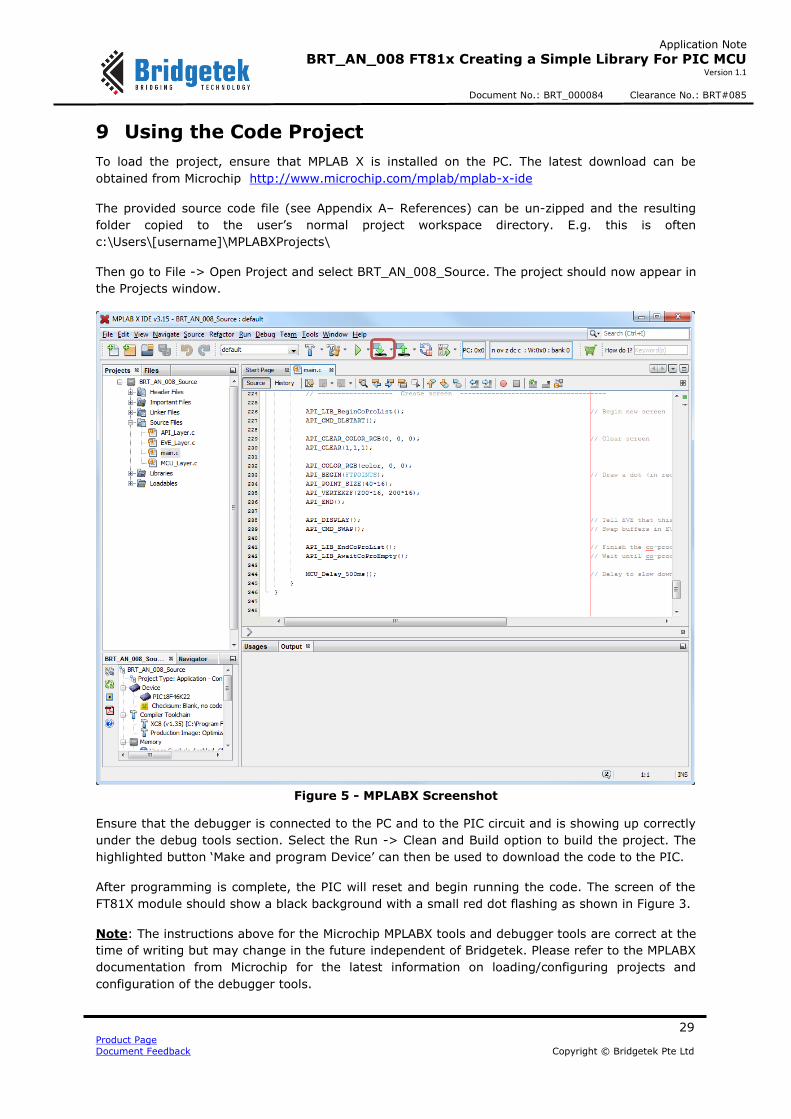
Figure 5 - MPLABX Screenshot
Ensure that the debugger is connected to the PC and to the PIC circuit and is showing up correctly
under the debug tools section. Select the Run -> Clean and Build option to build the project. The
highlighted button ‘Make and program Device’ can then be used to download the code to the PIC.
After programming is complete, the PIC will reset and begin running the code. The screen of the
FT81X module should show a black background with a small red dot flashing as shown in Figure 3.
Note: The instructions above for the Microchip MPLABX tools and debugger tools are correct at the
time of writing but may change in the future independent of Bridgetek. Please refer to the MPLABX
documentation from Microchip for the latest information on loading/configuring projects and
configuration of the debugger tools.

30 Product Page
Document Feedback Copyright © Bridgetek Pte Ltd
Application Note
BRT_AN_008 FT81x Creating a Simple Library For PIC MCU Version 1.1
Document No.: BRT_000084 Clearance No.: BRT#085
10 Conclusion
This application note has presented a simple example of a library for interfacing the FT81X series
to a PIC microcontroller. It is intended as a starting point for developers to customise in order to
create a library for their MCU platform.
The simple flashing dot example provided here in the main application can be extended to produce
a more complex real-world application.
It is recommended that readers refer to the application note BRT_AN_006 which provides
background information on the SPI data formatting used by EVE and an overview of how display
lists and co-processor lists are implemented. It is also assumed that the reader is familiar with the
FT81X Datasheet and Programmers guide which provide full details of the FT81X devices and their
API commands.

31 Product Page
Document Feedback Copyright © Bridgetek Pte Ltd
Application Note
BRT_AN_008 FT81x Creating a Simple Library For PIC MCU Version 1.1
Document No.: BRT_000084 Clearance No.: BRT#085
11 Contact Information
Head Quarters – Singapore Branch Office – Taipei, Taiwan Bridgetek Pte Ltd 178 Paya Lebar Road, #07-03 Singapore 409030 Tel: +65 6547 4827 Fax: +65 6841 6071
Bridgetek Pte Ltd, Taiwan Branch 2 Floor, No. 516, Sec. 1, Nei Hu Road, Nei Hu District Taipei 114 Taiwan , R.O.C. Tel: +886 (2) 8797 5691 Fax: +886 (2) 8751 9737
E-mail (Sales) [email protected] E-mail (Sales) [email protected] E-mail (Support) [email protected] E-mail (Support) [email protected]
Branch Office - Glasgow, United Kingdom Branch Office – Vietnam
Bridgetek Pte. Ltd. Unit 1, 2 Seaward Place, Centurion Business Park Glasgow G41 1HH United Kingdom Tel: +44 (0) 141 429 2777 Fax: +44 (0) 141 429 2758
Bridgetek VietNam Company Limited Lutaco Tower Building, 5th Floor, 173A Nguyen Van Troi, Ward 11, Phu Nhuan District, Ho Chi Minh City, Vietnam Tel : 08 38453222 Fax : 08 38455222
E-mail (Sales) [email protected] E-mail (Sales) [email protected] E-mail (Support) [email protected] E-mail (Support) [email protected]
Web Site
http://brtchip.com/
Distributor and Sales Representatives
Please visit the Sales Network page of the Bridgetek Web site for the contact details of our distributor(s) and
sales representative(s) in your country.
System and equipment manufacturers and designers are responsible to ensure that their systems, and any Bridgetek Pte Ltd
(BRTChip) devices incorporated in their systems, meet all applicable safety, regulatory and system-level performance
requirements. All application-related information in this document (including application descriptions, suggested Bridgetek
devices and other materials) is provided for reference only. While Bridgetek has taken care to assure it is accurate, this
information is subject to customer confirmation, and Bridgetek disclaims all liability for system designs and for any applications
assistance provided by Bridgetek. Use of Bridgetek devices in life support and/or safety applications is entirely at the user’s
risk, and the user agrees to defend, indemnify and hold harmless Bridgetek from any and all damages, claims, suits or expense
resulting from such use. This document is subject to change without notice. No freedom to use patents or other intellectual
property rights is implied by the publication of this document. Neither the whole nor any part of the information contained in,
or the product described in this document, may be adapted or reproduced in any material or electronic form without the prior
written consent of the copyright holder. Bridgetek Pte Ltd, 178 Paya Lebar Road, #07-03, Singapore 409030. Singapore
Registered Company Number: 201542387H.

32 Product Page
Document Feedback Copyright © Bridgetek Pte Ltd
Application Note
BRT_AN_008 FT81x Creating a Simple Library For PIC MCU Version 1.1
Document No.: BRT_000084 Clearance No.: BRT#085
Appendix A– References
Document References
BRT_AN_006
BRT_AN_007
FT81X
ME813-WH50C Datasheet
ME812-WH50R Datasheet
VM810C50A-D
FT81X Programmer Guide
FT81X Datasheet
EVE Examples (including BRT_AN_008.zip)
PIC18F46K22
PICKIT3
BRT_AN_008_Source Code
Acronyms and Abbreviations
Terms Description
EVE Embedded Video Engine
FT81x Latest version of the EVE family with enhanced feature set
LCD Liquid Crystal Display
MPLAB X Development environment software for PIC MCUs
PD# Power Down pin (active low) on the FT8xx
PIC PIC Microcontroller family from Microchip
SPI Serial Peripheral Interface
UART Universal Asynchronous Receiver Transmitter for serial data transfer

33 Product Page
Document Feedback Copyright © Bridgetek Pte Ltd
Application Note
BRT_AN_008 FT81x Creating a Simple Library For PIC MCU Version 1.1
Document No.: BRT_000084 Clearance No.: BRT#085
Appendix B– List of GPU and Co-Processor Commands
The following functions are provided in the API layer of the library.
GPU Instructions
void API_CLEAR_COLOR_RGB(uint8_t R, uint8_t G, uint8_t B); void API_CLEAR(uint8_t C, uint8_t S, uint8_t T); void API_COLOR_RGB(uint8_t R, uint8_t G, uint8_t B);
void API_VERTEX2F(int16_t x, int16_t y); void API_VERTEX2II(uint16_t x, uint16_t y, uint8_t handle,uint8_t cell); void API_BITMAP_HANDLE(uint8_t handle); void API_BITMAP_SOURCE(uint32_t addr); void API_BITMAP_LAYOUT(uint8_t format, uint16_t linestride, uint16_t height); void API_BITMAP_SIZE(uint8_t filter, uint8_t wrapx, uint8_t wrapy, uint16_t width,
uint16_t height);
void API_CELL(uint8_t cell); void API_TAG(uint8_t s); void API_ALPHA_FUNC(uint8_t func, uint8_t ref); void API_STENCIL_FUNC(uint8_t func, uint8_t ref, uint8_t mask); void API_BLEND_FUNC(uint8_t src, uint8_t dst); void API_STENCIL_OP(uint8_t sfail, uint8_t spass);
void API_POINT_SIZE(uint16_t size); void API_LINE_WIDTH(uint16_t width); void API_CLEAR_COLOR_A(uint8_t alpha); void API_COLOR_A(uint8_t alpha); void API_CLEAR_STENCIL(uint8_t s); void API_CLEAR_TAG(uint8_t s); void API_STENCIL_MASK(uint8_t mask);
void API_TAG_MASK(uint8_t mask); void API_SCISSOR_XY(uint16_t x, uint16_t y); void API_SCISSOR_SIZE(uint16_t width, uint16_t height);
void API_CALL(uint16_t dest); void API_JUMP(uint16_t dest); void API_BEGIN(uint8_t prim); void API_COLOR_MASK(uint8_t r, uint8_t g, uint8_t b, uint8_t a);
void API_END(void); void API_SAVE_CONTEXT(void); void API_RESTORE_CONTEXT(void); void API_RETURN(void); void API_MACRO(uint8_t m); void API_DISPLAY(void);
Co-Processor Commands
void API_CMD_TEXT(int16_t x, int16_t y, int16_t font, uint16_t options, const char* string);
void API_CMD_BUTTON(int16_t x, int16_t y, int16_t w, int16_t h, int16_t font, uint16_t options, const char* string);
void API_CMD_KEYS(int16_t x, int16_t y, int16_t w, int16_t h, int16_t font, uint16_t
options, const char* string); void API_CMD_NUMBER(int16_t x, int16_t y, int16_t font, uint16_t options, int32_t n); void API_CMD_LOADIDENTITY(void); void API_CMD_TOGGLE(int16_t x, int16_t y, int16_t w, int16_t font, uint16_t options,
uint16_t state, const char* string); void API_CMD_GAUGE(int16_t x, int16_t y, int16_t r, uint16_t options, uint16_t major,
uint16_t minor, uint16_t val, uint16_t range); void API_CMD_REGREAD(uint32_t ptr, uint32_t result);

34 Product Page
Document Feedback Copyright © Bridgetek Pte Ltd
Application Note
BRT_AN_008 FT81x Creating a Simple Library For PIC MCU Version 1.1
Document No.: BRT_000084 Clearance No.: BRT#085
void API_CMD_GETPROPS(uint32_t ptr, uint32_t w, uint32_t h); void API_CMD_MEMCPY(uint32_t dest, uint32_t src, uint32_t num); void API_CMD_SPINNER(int16_t x, int16_t y, uint16_t style, uint16_t scale);
void API_CMD_BGCOLOR(uint32_t c); void API_CMD_SWAP(void); void API_CMD_INFLATE(uint32_t ptr); void API_CMD_TRANSLATE(int32_t tx, int32_t ty); void API_CMD_STOP(void); void API_CMD_SLIDER(int16_t x, int16_t y, int16_t w, int16_t h, uint16_t options,
uint16_t val, uint16_t range);
void API_BITMAP_TRANSFORM_A(long a); void API_BITMAP_TRANSFORM_B(long b); void API_BITMAP_TRANSFORM_C(long c); void API_BITMAP_TRANSFORM_D(long d); void API_BITMAP_TRANSFORM_E(long e); void API_BITMAP_TRANSFORM_F(long f);
void API_CMD_INTERRUPT(uint32_t ms);
void API_CMD_FGCOLOR(uint32_t c); void API_CMD_ROTATE(int32_t a); void API_CMD_MEMWRITE(uint32_t ptr, uint32_t num); void API_CMD_SCROLLBAR(int16_t x, int16_t y, int16_t w, int16_t h, uint16_t options,
uint16_t val, uint16_t size, uint16_t range); void API_CMD_GETMATRIX(int32_t a, int32_t b, int32_t c, int32_t d, int32_t e, int32_t f);
void API_CMD_SKETCH(int16_t x, int16_t y, uint16_t w, uint16_t h, uint32_t ptr, uint16_t format);
void API_CMD_MEMSET(uint32_t ptr, uint32_t value, uint32_t num); void API_CMD_GRADCOLOR(uint32_t c); void API_CMD_BITMAP_TRANSFORM(int32_t x0, int32_t y0, int32_t x1, int32_t y1,
int32_t x2, int32_t y2, int32_t tx0, int32_t ty0, int32_t tx1, int32_t ty1, int32_t tx2, int32_t ty2, uint16_t result);
void API_CMD_CALIBRATE(uint32_t result); void API_CMD_SETFONT(uint32_t font, uint32_t ptr); void API_CMD_LOGO(void); void API_CMD_APPEND(uint32_t ptr, uint32_t num);
void API_CMD_MEMZERO(uint32_t ptr, uint32_t num); void API_CMD_SCALE(int32_t sx, int32_t sy);
void API_CMD_CLOCK(int16_t x, int16_t y, int16_t r, uint16_t options, uint16_t h, uint16_t m, uint16_t s, uint16_t ms);
void API_CMD_GRADIENT(int16_t x0, int16_t y0, uint32_t rgb0, int16_t x1, int16_t y1, uint32_t rgb1);
void API_CMD_SETMATRIX(void); void API_CMD_TRACK(int16_t x, int16_t y, int16_t w, int16_t h, int16_t tag); void API_CMD_GETPTR(uint32_t result);
void API_CMD_PROGRESS(int16_t x, int16_t y, int16_t w, int16_t h, uint16_t options, uint16_t val, uint16_t range);
void API_CMD_COLDSTART(void); void API_CMD_DIAL(int16_t x, int16_t y, int16_t r, uint16_t options, uint16_t val); void API_CMD_LOADIMAGE(uint32_t ptr, uint32_t options); void API_CMD_DLSTART(void); void API_CMD_SNAPSHOT(uint32_t ptr);
void API_CMD_SCREENSAVER(void);
void API_CMD_MEMCRC(uint32_t ptr, uint32_t num, uint32_t result);
GPU Instructions (FT81X)
void API_VERTEX_FORMAT(uint8_t frac); void API_BITMAP_LAYOUT_H(uint8_t linestride, uint8_t height);
void API_BITMAP_SIZE_H(uint8_t width, uint8_t height); void API_PALETTE_SOURCE(uint32_t addr);

35 Product Page
Document Feedback Copyright © Bridgetek Pte Ltd
Application Note
BRT_AN_008 FT81x Creating a Simple Library For PIC MCU Version 1.1
Document No.: BRT_000084 Clearance No.: BRT#085
void API_VERTEX_TRANSLATE_X(uint32_t x); void API_VERTEX_TRANSLATE_Y(uint32_t y); void API_NOP(void);
Co-Processor Commands (FT81X)
void API_CMD_VIDEOSTART(void); void API_CMD_SETROTATE(uint32_t r);
void API_CMD_SETFONT2(uint32_t font, uint32_t ptr, uint32_t firstchar); void API_CMD_MEDIAFIFO(uint32_t ptr, uint32_t size); void API_CMD_SNAPSHOT2(uint32_t fmt, uint32_t ptr, int16_t x, int16_t y, int16_t w,
int16_t h); void API_CMD_INT_SWLOADIMAGE(uint32_t ptr, uint32_t options); void API_CMD_CSKETCH(int16_t x, int16_t y, uint16_t w, uint16_t h, uint32_t ptr,
uint16_t format,uint16_t freq);
void API_CMD_ROMFONT(uint32_t font, uint32_t romslot); void API_CMD_PLAYVIDEO(uint32_t options); void API_CMD_SYNC(void); void API_CMD_VIDEOFRAME(uint32_t dst, uint32_t ptr); void API_CMD_SETBASE(uint32_t base); void API_CMD_SETBITMAP(uint32_t source, uint16_t fmt, uint16_t w, uint16_t h);
void API_CMD_SETSCRATCH(uint32_t handle);

36 Product Page
Document Feedback Copyright © Bridgetek Pte Ltd
Application Note
BRT_AN_008 FT81x Creating a Simple Library For PIC MCU Version 1.1
Document No.: BRT_000084 Clearance No.: BRT#085
Appendix C – List of Tables & Figures
List of Figures
Figure 1 - Schematic of the PIC MCU with ME812-WH50R .................................................................. 5
Figure 2 - Layers of the Software Example ....................................................................................... 6
Figure 3 - Flashing Dot Demo ....................................................................................................... 14
Figure 4 - Sending Data to the Co-Processor .................................................................................. 19
Figure 5 - MPLABX Screenshot ...................................................................................................... 29
List of Tables
NA

37 Product Page
Document Feedback Copyright © Bridgetek Pte Ltd
Application Note
BRT_AN_008 FT81x Creating a Simple Library For PIC MCU Version 1.1
Document No.: BRT_000084 Clearance No.: BRT#085
Appendix D– Revision History
Document Title: BRT_AN_008 FT81x Creating a Simple Library For PIC MCU
Document Reference No.: BRT_000084
Clearance No.: BRT#085
Product Page: http://brtchip.com/i-ft8/
Document Feedback: Send Feedback
Revision Changes Date
1.0 Initial version 2017-07-07
1.1
Added information on running code on FT81X vs FT81X (section 3.4)
Added information on Creating Co-Processor Lists in Sections (in section 4)
2018-03-27