ftfs chap17 p083
DESCRIPTION
thermalTRANSCRIPT
Chapter 17 Steady Heat Conduction
Critical Radius Of Insulation
17-83C In a cylindrical pipe or a spherical shell, the additional insulation increases the conduction resistance of insulation, but decreases the convection resistance of the surface because of the increase in the outer surface area. Due to these opposite effects, a critical radius of insulation is defined as the outer radius that provides maximum rate of heat transfer. For a cylindrical layer, it is defined as r k hcr / where k is the thermal conductivity of insulation and h is the external convection heat transfer coefficient.
17-84C It will decrease.
17-85C Yes, the measurements can be right. If the radius of insulation is less than critical radius of insulation of the pipe, the rate of heat loss will increase.
17-86C No.
17-87C For a cylindrical pipe, the critical radius of insulation is defined as r k hcr / . On windy days, the external convection heat transfer coefficient is greater compared to calm days. Therefore critical radius of insulation will be greater on calm days.
17-88 An electric wire is tightly wrapped with a 1-mm thick plastic cover. The interface temperature and the effect of doubling the thickness of the plastic cover on the interface temperature are to be determined.Assumptions 1 Heat transfer is steady since there is no indication of any change with time. 2 Heat transfer is one-dimensional since there is thermal symmetry about the centerline and no variation in the axial direction. 3 Thermal properties are constant. 4 The thermal contact resistance at the interface is negligible. 5 Heat transfer coefficient accounts for the radiation effects, if any.Properties The thermal conductivity of plastic cover is given to be k = 0.15 W/m°C.Analysis In steady operation, the rate of heat transfer from the wire is equal to the heat generated within the wire,
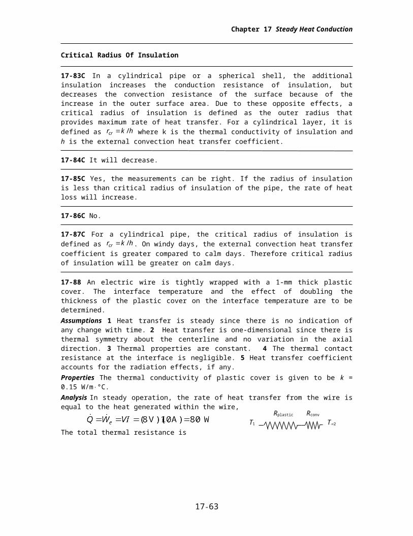
The total thermal resistance is
Then the interface temperature becomes
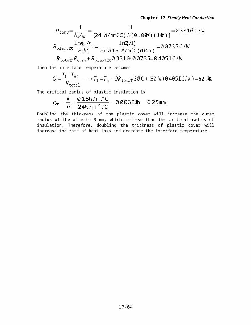
The critical radius of plastic insulation is
Doubling the thickness of the plastic cover will increase the outer radius of the wire to 3 mm, which is less than the critical radius of insulation. Therefore, doubling the thickness of plastic cover will increase the rate of heat loss and decrease the interface temperature.
17-63
Rconv
T2
Rplastic
T1
Chapter 17 Steady Heat Conduction
17-89E An electrical wire is covered with 0.02-in thick plastic insulation. It is to be determined if the plastic insulation on the wire will increase or decrease heat transfer from the wire.
Assumptions 1 Heat transfer from the wire is steady since there is no indication of any change with time. 2 Heat transfer is one-dimensional since there is thermal symmetry about the centerline and no variation in the axial direction. 3 Thermal properties are constant. 4 The thermal contact resistance at the interface is negligible.
Properties The thermal conductivity of plastic cover is given to be k = 0.075 Btu/hft°F.
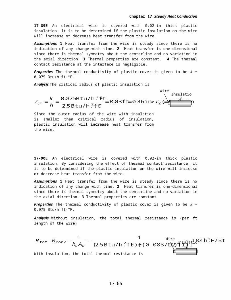
Analysis The critical radius of plastic insulation is
Since the outer radius of the wire with insulation is smaller than critical radius of insulation, plastic insulation will increase heat transfer from the wire.
17-90E An electrical wire is covered with 0.02-in thick plastic insulation. By considering the effect of thermal contact resistance, it is to be determined if the plastic insulation on the wire will increase or decrease heat transfer from the wire.
Assumptions 1 Heat transfer from the wire is steady since there is no indication of any change with time. 2 Heat transfer is one-dimensional since there is thermal symmetry about the centerline and no variation in the axial direction. 3 Thermal properties are constant
Properties The thermal conductivity of plastic cover is given to be k = 0.075 Btu/hft°F.
Analysis Without insulation, the total thermal resistance is (per ft length of the wire)
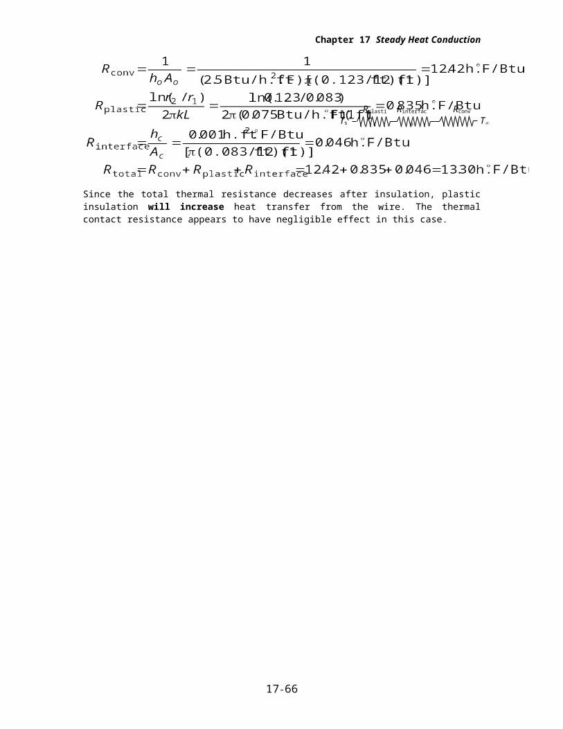
With insulation, the total thermal resistance is
Since the total thermal resistance decreases after insulation, plastic insulation will increase heat transfer from the wire. The thermal contact resistance appears to have negligible effect in this case.
17-64
WireInsulation
WireInsulation
Rplastic Rinterface Rconv
Ts T
Chapter 17 Steady Heat Conduction
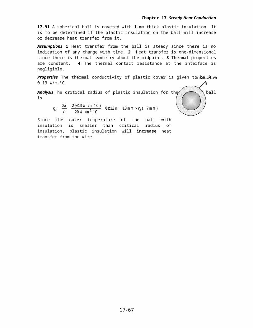
17-91 A spherical ball is covered with 1-mm thick plastic insulation. It is to be determined if the plastic insulation on the ball will increase or decrease heat transfer from it.
Assumptions 1 Heat transfer from the ball is steady since there is no indication of any change with time. 2 Heat transfer is one-dimensional since there is thermal symmetry about the midpoint. 3 Thermal properties are constant. 4 The thermal contact resistance at the interface is negligible.
Properties The thermal conductivity of plastic cover is given to be k = 0.13 W/m°C.
Analysis The critical radius of plastic insulation for the spherical ball is
rk
hrcr
2 2 013
200 013 13 2
( ..
W / m. C)
W / m . C m mm ( 7 mm)
2
Since the outer temperature of the ball with insulation is smaller than critical radius of insulation, plastic insulation will increase heat transfer from the wire.
17-65
Insulation
Chapter 17 Steady Heat Conduction
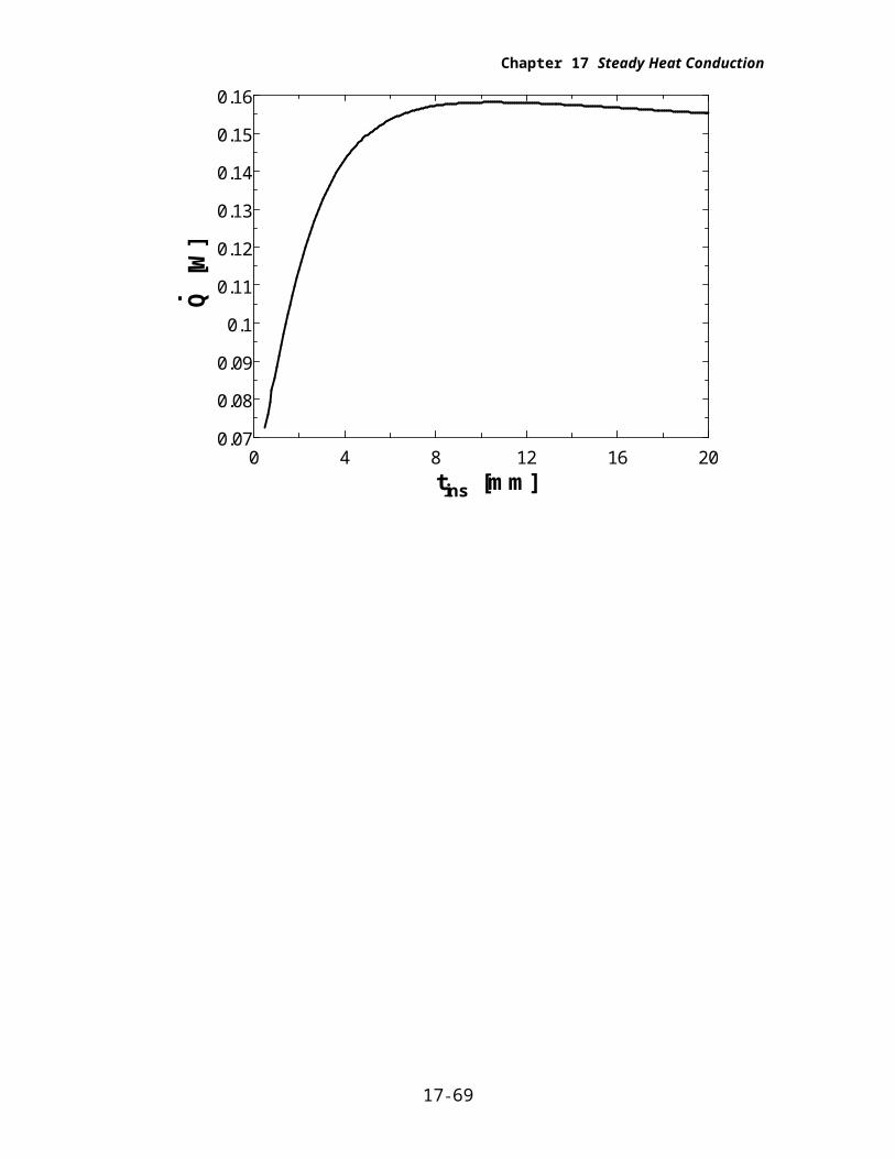
17-92
"GIVEN"D_1=0.005 "[m]""t_ins=1 [mm], parameter to be varied"k_ins=0.13 "[W/m-C]"T_ball=50 "[C]"T_infinity=15 "[C]"h_o=20 "[W/m^2-C]"
"ANALYSIS"D_2=D_1+2*t_ins*Convert(mm, m)A_o=pi*D_2^2R_conv_o=1/(h_o*A_o)R_ins=(r_2-r_1)/(4*pi*r_1*r_2*k_ins)r_1=D_1/2r_2=D_2/2R_total=R_conv_o+R_insQ_dot=(T_ball-T_infinity)/R_total
tins [mm] Q [W]0.5 0.07248
1.526 0.10352.553 0.12523.579 0.1394.605 0.14745.632 0.15236.658 0.15527.684 0.15698.711 0.15779.737 0.158110.76 0.158111.79 0.15812.82 0.157813.84 0.157414.87 0.157115.89 0.156716.92 0.156317.95 0.155918.97 0.1556
20 0.1552
17-66
Chapter 17 Steady Heat Conduction
0 4 8 12 16 200.07
0.08
0.09
0.1
0.11
0.12
0.13
0.14
0.15
0.16
tins [mm]
Q [
W]
17-67

Chapter 17 Steady Heat Conduction
Heat Transfer From Finned Surfaces
17-93C Increasing the rate of heat transfer from a surface by increasing the heat transfer surface area.
17-94C The fin efficiency is defined as the ratio of actual heat transfer rate from the fin to the ideal heat transfer rate from the fin if the entire fin were at base temperature, and its value is between 0 and 1. Fin effectiveness is defined as the ratio of heat transfer rate from a finned surface to the heat transfer rate from the same surface if there were no fins, and its value is expected to be greater than 1.
17-95C Heat transfer rate will decrease since a fin effectiveness smaller than 1 indicates that the fin acts as insulation.
17-96C Fins enhance heat transfer from a surface by increasing heat transfer surface area for convection heat transfer. However, adding too many fins on a surface can suffocate the fluid and retard convection, and thus it may cause the overall heat transfer coefficient and heat transfer to decrease.
17-97C Effectiveness of a single fin is the ratio of the heat transfer rate from the entire exposed surface of the fin to the heat transfer rate from the fin base area. The overall effectiveness of a finned surface is defined as the ratio of the total heat transfer from the finned surface to the heat transfer from the same surface if there were no fins.
17-98C Fins should be attached on the air side since the convection heat transfer coefficient is lower on the air side than it is on the water side.
17-99C Fins should be attached to the outside since the heat transfer coefficient inside the tube will be higher due to forced convection. Fins should be added to both sides of the tubes when the convection coefficients at the inner and outer surfaces are comparable in magnitude.
17-68
Chapter 17 Steady Heat Conduction
17-100C Welding or tight fitting introduces thermal contact resistance at the interface, and thus retards heat transfer. Therefore, the fins formed by casting or extrusion will provide greater enhancement in heat transfer.
17-101C If the fin is too long, the temperature of the fin tip will approach the surrounding temperature and we can neglect heat transfer from the fin tip. Also, if the surface area of the fin tip is very small compared to the total surface area of the fin, heat transfer from the tip can again be neglected.
17-102C Increasing the length of a fin decreases its efficiency but increases its effectiveness.
17-103C Increasing the diameter of a fin will increase its efficiency but decrease its effectiveness.
17-104C The thicker fin will have higher efficiency; the thinner one will have higher effectiveness.
17-105C The fin with the lower heat transfer coefficient will have the higher efficiency and the higher effectiveness.
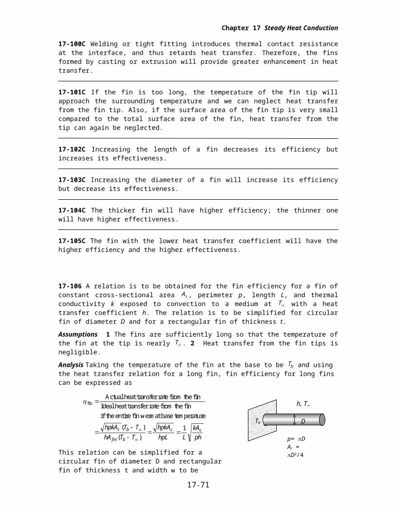
17-106 A relation is to be obtained for the fin efficiency for a fin of constant cross-sectional area , perimeter p, length L, and thermal conductivity k exposed to convection to a medium at with a heat transfer coefficient h. The relation is to be simplified for circular fin of diameter D and for a rectangular fin of thickness t.
Assumptions 1 The fins are sufficiently long so that the temperature of the fin at the tip is nearly . 2 Heat transfer from the fin tips is negligible.
Analysis Taking the temperature of the fin at the base to be and using the heat transfer relation for a long fin, fin efficiency for long fins can be expressed as
finActual heat transfer rate from the fin
Ideal heat transfer rate from the fin
if the entire fin were at base temperature
hpkA T T
hA T T
hpkA
hpL L
kA
phc b
fin b
c c( )
( )
1
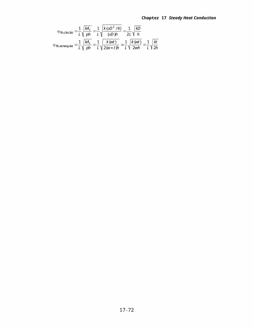
This relation can be simplified for a circular fin of diameter D and rectangular fin of thickness t and width w to be
fin,circular
fin,rectangular
1 1 4 1
2
1 1
2
1
2
1
2
2
L
kA
ph L
k D
D h L
kD
h
L
kA
ph L
k wt
w t h L
k wt
wh L
kt
h
c
c
( / )
( )
( )
( )
( )
17-69
h, T
D
p= DAc = D2/4
Tb
Chapter 17 Steady Heat Conduction
17-107 The maximum power rating of a transistor whose case temperature is not to exceed 80 is to be determined.
Assumptions 1 Steady operating conditions exist. 2 The transistor case is isothermal at 80 .
Properties The case-to-ambient thermal resistance is given to be 20.
Analysis The maximum power at which this transistor can be operated safely is
17-108 A commercially available heat sink is to be selected to keep the case temperature of a transistor below in an environment at 20 .
Assumptions 1 Steady operating conditions exist. 2 The transistor case is isothermal at 90 . 3 The contact resistance between the transistor and the heat sink is negligible.
Analysis The thermal resistance between the transistor attached to the sink and the ambient air is determined to be
( )Q
T
RR
T T
Q
case ambientcase ambient
transistor C
W
90 20
401.75 C / W
The thermal resistance of the heat sink must be below 175. C / Wo . Table 17-4 reveals that HS6071 in vertical position, HS5030 and HS6115 in both horizontal and vertical position can be selected.
17-109 A commercially available heat sink is to be selected to keep the case temperature of a transistor below in an environment at 35 .
Assumptions 1 Steady operating conditions exist. 2 The transistor case is isothermal at 80 . 3 The contact resistance between the transistor and the heat sink is negligible.
Analysis The thermal resistance between the transistor attached to the sink and the ambient air is determined to be
( )Q
T
RR
T T
Q
case ambientcase ambient
transistor C
W
80 35
301.5 C / W
The thermal resistance of the heat sink must be below 15. C / Wo . Table 17-4 reveals that HS5030 in both horizontal and vertical positions, HS6071 in vertical position, and HS6115 in both horizontal and vertical positions can be selected.
17-70
T
RTs
T
RTs
T
RTs
25C
180C
Chapter 17 Steady Heat Conduction
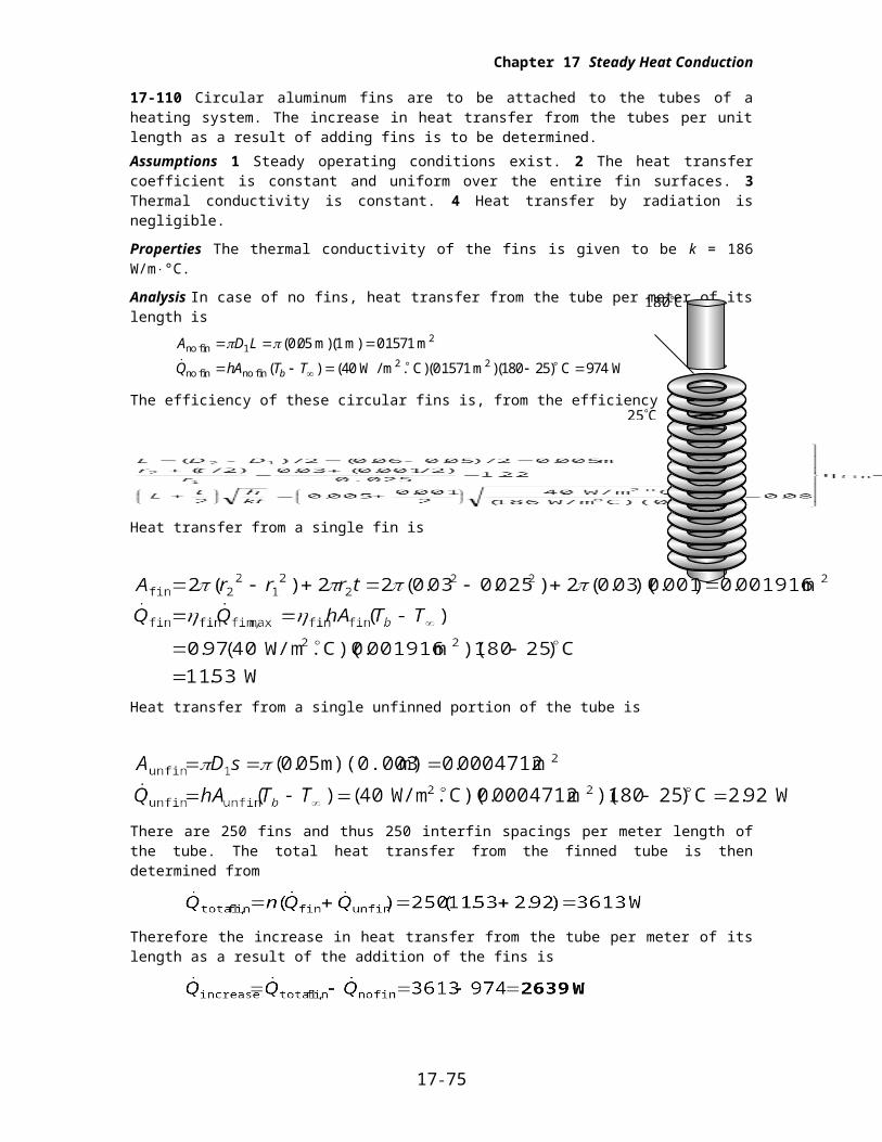
17-110 Circular aluminum fins are to be attached to the tubes of a heating system. The increase in heat transfer from the tubes per unit length as a result of adding fins is to be determined.
Assumptions 1 Steady operating conditions exist. 2 The heat transfer coefficient is constant and uniform over the entire fin surfaces. 3 Thermal conductivity is constant. 4 Heat transfer by radiation is negligible.
Properties The thermal conductivity of the fins is given to be k = 186 W/m°C.
Analysis In case of no fins, heat transfer from the tube per meter of its length is
A D L
Q hA T Tb
no fin2
no fin no fin2 2
m m m
W / m C m C W
1 0 05 1 01571
40 01571 180 25 974
( . )( ) .
( ) ( . )( . )( )
The efficiency of these circular fins is, from the efficiency curve,
Heat transfer from a single fin is
Heat transfer from a single unfinned portion of the tube is
There are 250 fins and thus 250 interfin spacings per meter length of the tube. The total heat transfer from the finned tube is then determined from
Therefore the increase in heat transfer from the tube per meter of its length as a result of the addition of the fins is
17-71
Chapter 17 Steady Heat Conduction
17-111E The handle of a stainless steel spoon partially immersed in boiling water extends 7 in. in the air from the free surface of the water. The temperature difference across the exposed surface of the spoon handle is to be determined.
Assumptions 1 The temperature of the submerged portion of the spoon is equal to the water temperature. 2 The temperature in the spoon varies in the axial direction only (along the spoon), T(x). 3 The heat transfer from the tip of the spoon is negligible. 4 The heat transfer coefficient is constant and uniform over the entire spoon surface. 5 The thermal properties of the spoon are constant. 6 The heat transfer coefficient accounts for the effect of radiation from the spoon..
Properties The thermal conductivity of the spoon is given to be k = 8.7 Btu/hft°F.
Analysis Noting that the cross-sectional area of the spoon is constant and measuring x from the free surface of water, the variation of temperature along the spoon can be expressed as
T x T
T T
a L x
aLb
( ) cosh ( )
cosh
where
p
Ac
2 0 5 12 0 08 12 0 0967
0 5 12 0 08 12 0 000278
( . / . / ) .
( . / . / ) .
ft ft ft
ft)( ft ft2
ahp
kAc
( )( . )
( . )( . ).
3 0 0967
8 7 0 00027810 95
Btu / h.ft . F ft
Btu / h.ft. F ft ft
2
2-1
Noting that x = L = 7/12=0.583 ft at the tip and substituting, the tip temperature of the spoon is determined to be
Therefore, the temperature difference across the exposed section of the spoon handle is
17-72
h, T
D
Tb
0.5 in
0.08 in
L = 7 in

h, T
D
Tb
L = 7 in0.5 in
0.08 in
Chapter 17 Steady Heat Conduction
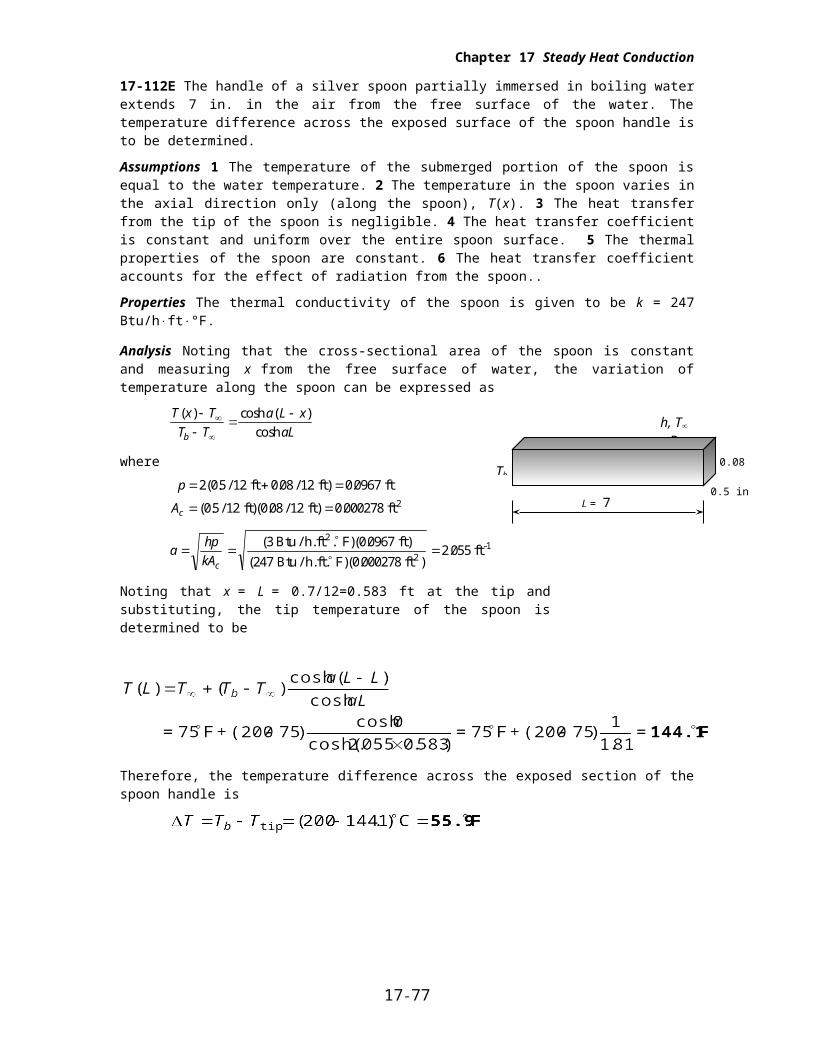
17-112E The handle of a silver spoon partially immersed in boiling water extends 7 in. in the air from the free surface of the water. The temperature difference across the exposed surface of the spoon handle is to be determined.
Assumptions 1 The temperature of the submerged portion of the spoon is equal to the water temperature. 2 The temperature in the spoon varies in the axial direction only (along the spoon), T(x). 3 The heat transfer from the tip of the spoon is negligible. 4 The heat transfer coefficient is constant and uniform over the entire spoon surface. 5 The thermal properties of the spoon are constant. 6 The heat transfer coefficient accounts for the effect of radiation from the spoon..
Properties The thermal conductivity of the spoon is given to be k = 247 Btu/hft°F.
Analysis Noting that the cross-sectional area of the spoon is constant and measuring x from the free surface of water, the variation of temperature along the spoon can be expressed as
T x T
T T
a L x
aLb
( ) cosh ( )
cosh
where
p
Ac
2 0 5 12 0 08 12 0 0967
0 5 12 0 08 12 0 000278
( . / . / ) .
( . / . / ) .
ft ft ft
ft)( ft ft2
ahp
kAc
( )( . )
( )( . ).
3 0 0967
247 0 0002782 055
Btu / h.ft . F ft
Btu / h.ft. F ft ft
2
2-1
Noting that x = L = 0.7/12=0.583 ft at the tip and substituting, the tip temperature of the spoon is determined to be
Therefore, the temperature difference across the exposed section of the spoon handle is
17-73

Chapter 17 Steady Heat Conduction
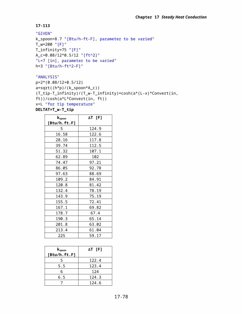
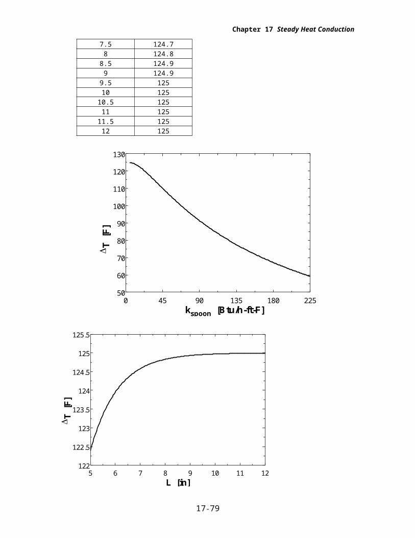
17-113
"GIVEN"k_spoon=8.7 "[Btu/h-ft-F], parameter to be varied"T_w=200 "[F]"T_infinity=75 "[F]"A_c=0.08/12*0.5/12 "[ft^2]""L=7 [in], parameter to be varied"h=3 "[Btu/h-ft^2-F]"
"ANALYSIS"p=2*(0.08/12+0.5/12)a=sqrt((h*p)/(k_spoon*A_c))(T_tip-T_infinity)/(T_w-T_infinity)=cosh(a*(L-x)*Convert(in, ft))/cosh(a*L*Convert(in, ft))x=L "for tip temperature"DELTAT=T_w-T_tip
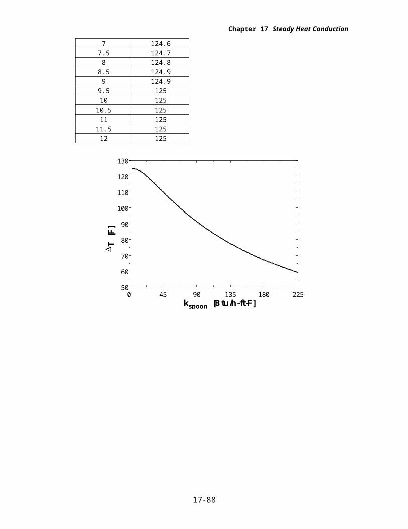
kspoon [Btu/h.ft.F] T [F]5 124.9
16.58 122.628.16 117.839.74 112.551.32 107.162.89 10274.47 97.2186.05 92.7897.63 88.69109.2 84.91120.8 81.42132.4 78.19143.9 75.19155.5 72.41167.1 69.82178.7 67.4190.3 65.14201.8 63.02213.4 61.04225 59.17
kspoon [Btu/h.ft.F] T [F]5 122.4
5.5 123.46 124
6.5 124.37 124.6
7.5 124.78 124.8
8.5 124.99 124.9
9.5 12510 125
10.5 12511 125
11.5 12512 125
17-74
Chapter 17 Steady Heat Conduction
0 45 90 135 180 22550
60
70
80
90
100
110
120
130
kspoon [Btu/h-ft-F]
T [
F]
5 6 7 8 9 10 11 12122
122.5
123
123.5
124
124.5
125
125.5
L [in]
T [
F]
17-75

Chapter 17 Steady Heat Conduction
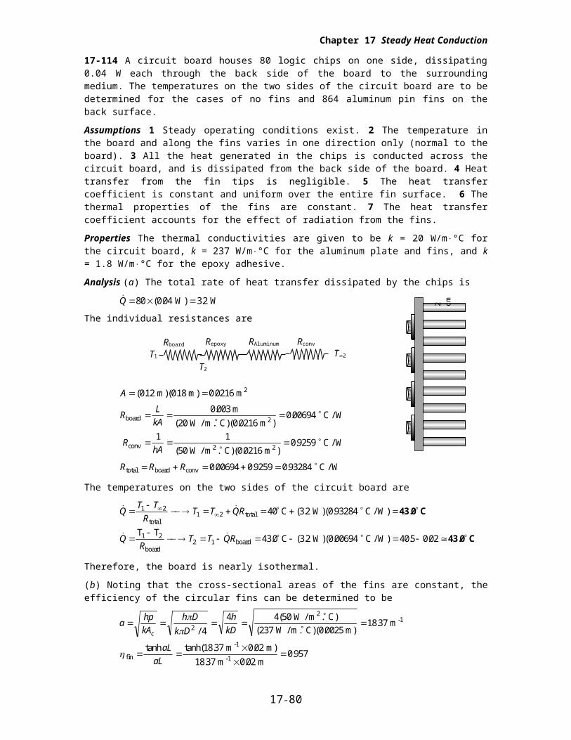
17-114 A circuit board houses 80 logic chips on one side, dissipating 0.04 W each through the back side of the board to the surrounding medium. The temperatures on the two sides of the circuit board are to be determined for the cases of no fins and 864 aluminum pin fins on the back surface.
Assumptions 1 Steady operating conditions exist. 2 The temperature in the board and along the fins varies in one direction only (normal to the board). 3 All the heat generated in the chips is conducted across the circuit board, and is dissipated from the back side of the board. 4 Heat transfer from the fin tips is negligible. 5 The heat transfer coefficient is constant and uniform over the entire fin surface. 6 The thermal properties of the fins are constant. 7 The heat transfer coefficient accounts for the effect of radiation from the fins.
Properties The thermal conductivities are given to be k = 20 W/m°C for the circuit board, k = 237 W/m°C for the aluminum plate and fins, and k = 1.8 W/m°C for the epoxy adhesive.
Analysis (a) The total rate of heat transfer dissipated by the chips is
( . .Q 80 0 04 32 W) W
The individual resistances are
A ( . ( . .012 018 0 0216 m) m) m2
RL
kA
RhA
board 2
conv 2 2
m
W / m. C) m C / W
W / m . C) m C / W
0 003
20 0 02160 00694
1 1
50 0 02160 9259
.
( ( . ).
( ( . ).
R R Rtotal board conv C / W 0 00694 0 9259 0 93284. . .
The temperatures on the two sides of the circuit board are
( . )( .
. ( . )( . . .
QT T
RT T QR
QR
T T QR
1 21 2
2 1
40 32 0 93284
43 0 32 0 00694 40 5 0 02
totaltotal
1 2
boardboard
C W C / W)
T TC W C / W)
43.0 C
43.0 C
Therefore, the board is nearly isothermal.
(b) Noting that the cross-sectional areas of the fins are constant, the efficiency of the circular fins can be determined to be
ahp
kA
h D
k D
h
kDc
2 4
4 4 50
237 0 002518 37
/
( )
( )( . ).
W / m . C
W / m. C m m
2-1
fin
-1
-1
m m
m m
tanh tanh( . . )
. ..
aL
aL
18 37 0 02
18 37 0 020 957
The fins can be assumed to be at base temperature provided that the fin area is modified by multiplying it by 0.957. Then the various thermal resistances are
RL
kAepoxy 2
m
W / m. C) m C / W
0 0002
18 0 02160 0051
.
( . ( . ).
RL
kAAl 2
m
W / m. C) m C / W
0 002
237 0 02160 00039
.
( ( . ).
17-76
2 cm
Rboard
T1
RAluminum Rconv
T2
Repoxy
T2
Chapter 17 Steady Heat Conduction
A n DL
AD
A A A
finned fin2
unfinned2
total,with fins finned unfinned2
m) m) m
m
m
0 957 864 0 0025 0 02 0130
0 0216 8644
0 0216 8640 0025
40 0174
0130 0 017 0147
2 2
. ( . ( . .
. .( . )
.
. . .
RhAconv
total,with fins2 2 W / m . C) m
C / W
1 1
50 014701361
( ( . ).
R R R R Rtotal board epoxy aluminum conv
C / W
0 00694 0 0051 0 00039 01361 01484. . . . .
Then the temperatures on the two sides of the circuit board becomes
( . )( .
. ( . )( . . .
QT T
RT T QR
QT T
RT T QR
1 21 2
1 22 1
40 3 2 01484
40 5 32 0 00694 40 5 0 02
totaltotal
boardboard
C W C / W)
C W C / W)
40.5 C
40.5 C
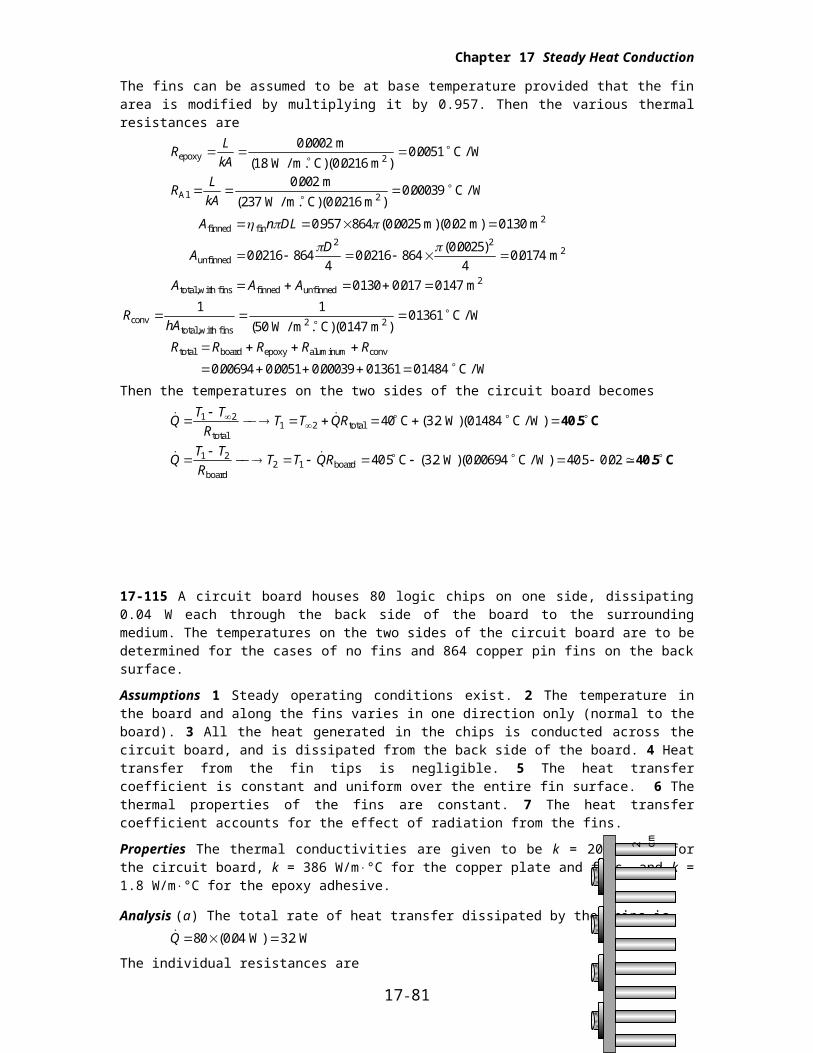
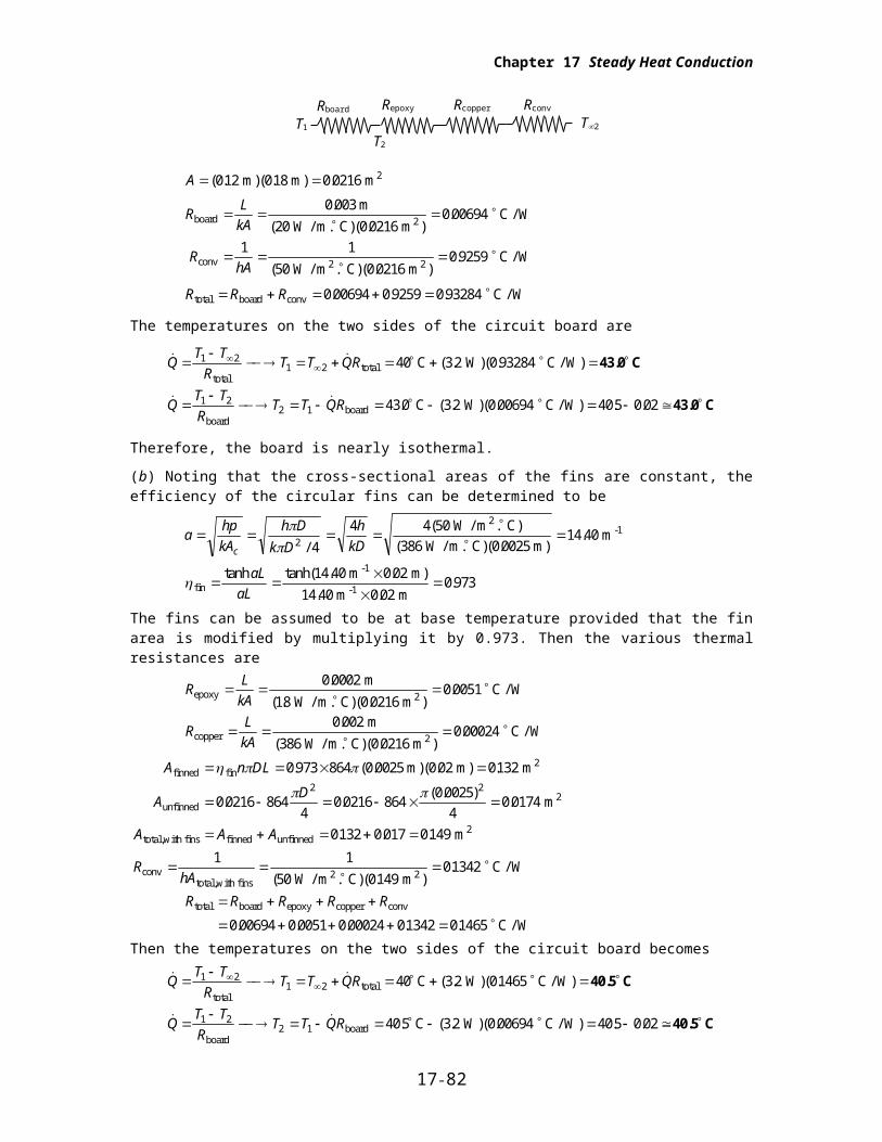
17-115 A circuit board houses 80 logic chips on one side, dissipating 0.04 W each through the back side of the board to the surrounding medium. The temperatures on the two sides of the circuit board are to be determined for the cases of no fins and 864 copper pin fins on the back surface.
Assumptions 1 Steady operating conditions exist. 2 The temperature in the board and along the fins varies in one direction only (normal to the board). 3 All the heat generated in the chips is conducted across the circuit board, and is dissipated from the back side of the board. 4 Heat transfer from the fin tips is negligible. 5 The heat transfer coefficient is constant and uniform over the entire fin surface. 6 The thermal properties of the fins are constant. 7 The heat transfer coefficient accounts for the effect of radiation from the fins.
Properties The thermal conductivities are given to be k = 20 W/m°C for the circuit board, k = 386 W/m°C for the copper plate and fins, and k = 1.8 W/m°C for the epoxy adhesive.
Analysis (a) The total rate of heat transfer dissipated by the chips is ( . .Q 80 0 04 32 W) W
The individual resistances are
A ( . ( . .012 018 0 0216 m) m) m2
RL
kA
RhA
board 2
conv 2 2
m
W / m. C) m C / W
W / m . C) m C / W
0 003
20 0 02160 00694
1 1
50 0 02160 9259
.
( ( . ).
( ( . ).
R R Rtotal board conv C / W 0 00694 0 9259 0 93284. . .
The temperatures on the two sides of the circuit board are
17-77
2 cm
Rboard
T1
Rcopper Rconv
T2
Repoxy
T2
Chapter 17 Steady Heat Conduction
( . )( .
. ( . )( . . .
QT T
RT T QR
QT T
RT T QR
1 21 2
1 22 1
40 3 2 0 93284
43 0 32 0 00694 40 5 0 02
totaltotal
boardboard
C W C / W)
C W C / W)
43.0 C
43.0 C
Therefore, the board is nearly isothermal.
(b) Noting that the cross-sectional areas of the fins are constant, the efficiency of the circular fins can be determined to be
ahp
kA
h D
k D
h
kDc
2 4
4 4 50
386 0 002514 40
/
( )
( )( . ).
W / m . C
W / m. C m m
2-1
fin
-1
-1
m m
m m
tanh tanh( . . )
. ..
aL
aL
14 40 0 02
14 40 0 020 973
The fins can be assumed to be at base temperature provided that the fin area is modified by multiplying it by 0.973. Then the various thermal resistances are
RL
kAepoxy 2
m
W / m. C) m C / W
0 0002
18 0 02160 0051
.
( . ( . ).
RL
kAcopper 2
m
W / m. C) m C / W
0 002
386 0 02160 00024
.
( ( . ).
A n DL
AD
A A A
finned fin2
unfinned2
total,with fins finned unfinned2
m) m) m
m
m
0 973 864 0 0025 0 02 0132
0 0216 8644
0 0216 8640 0025
40 0174
0132 0 017 0149
2 2
. ( . ( . .
. .( . )
.
. . .
RhAconv
total,with fins2 2 W / m . C) m
C / W
1 1
50 014901342
( ( . ).
R R R R Rtotal board epoxy copper conv
C / W
0 00694 0 0051 0 00024 01342 01465. . . . .
Then the temperatures on the two sides of the circuit board becomes
( . )( .
. ( . )( . . .
QT T
RT T QR
QT T
RT T QR
1 21 2
1 22 1
40 3 2 01465
40 5 32 0 00694 40 5 0 02
totaltotal
boardboard
C W C / W)
C W C / W)
40.5 C
40.5 C
17-78
Chapter 17 Steady Heat Conduction
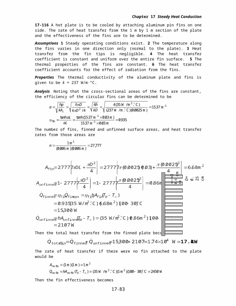
17-116 A hot plate is to be cooled by attaching aluminum pin fins on one side. The rate of heat transfer from the 1 m by 1 m section of the plate and the effectiveness of the fins are to be determined.
Assumptions 1 Steady operating conditions exist. 2 The temperature along the fins varies in one direction only (normal to the plate). 3 Heat transfer from the fin tips is negligible. 4 The heat transfer coefficient is constant and uniform over the entire fin surface. 5 The thermal properties of the fins are constant. 6 The heat transfer coefficient accounts for the effect of radiation from the fins.
Properties The thermal conductivity of the aluminum plate and fins is given to be k = 237 W/m°C.
Analysis Noting that the cross-sectional areas of the fins are constant, the efficiency of the circular fins can be determined to be
ahp
kA
h D
k D
h
kDc
2 4
4 4 35
237 0 00251537
/
( )
( )( . ).
W / m . C
W / m. C m m
2-1
fin
-1
-1
m m
m m
tanh tanh( . . )
. ..
aL
aL
15 37 0 03
15 37 0 030 935
The number of fins, finned and unfinned surface areas, and heat transfer rates from those areas are
n 1
0 006 0 00627 777
m
m) m)
2
( . ( .,
Then the total heat transfer from the finned plate becomes
The rate of heat transfer if there were no fin attached to the plate would be
A
Q hA T Tb
no fin2
no fin no fin2 2
m m m
W / m C m C W
( )( )
( ) ( . )( )( )
1 1 1
35 1 100 30 2450
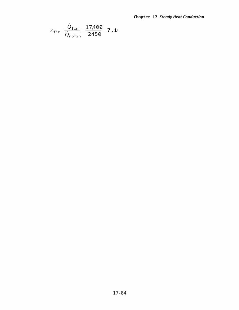
Then the fin effectiveness becomes
17-79
3 cm0.
6 cm
D=
0.2
5 cm
Chapter 17 Steady Heat Conduction
17-117 A hot plate is to be cooled by attaching aluminum pin fins on one side. The rate of heat transfer from the 1 m by 1 m section of the plate and the effectiveness of the fins are to be determined.
Assumptions 1 Steady operating conditions exist. 2 The temperature along the fins varies in one direction only (normal to the plate). 3 Heat transfer from the fin tips is negligible. 4 The heat transfer coefficient is constant and uniform over the entire fin surface. 5 The thermal properties of the fins are constant. 6 The heat transfer coefficient accounts for the effect of radiation from the fins.
Properties The thermal conductivity of the aluminum plate and fins is given to be k = 237 W/m°C.
Analysis Noting that the cross-sectional areas of the fins are constant, the efficiency of the circular fins can be determined to be
ahp
kA
h D
k D
h
kDc
2 4
4 4 35
386 0 002512 04
/
( )
( )( . ).
W / m . C
W / m. C m m
2-1
fin
-1
-1
m m
m m
tanh tanh( . . )
. ..
aL
aL
12 04 0 03
12 04 0 030 959
The number of fins, finned and unfinned surface areas, and heat transfer rates from those areas are
n 1
0 006 0 00627777
m
m) m)
2
( . ( .
Then the total heat transfer from the finned plate becomes
The rate of heat transfer if there were no fin attached to the plate would be
A
Q hA T Tb
no fin2
no fin no fin2 2
m m m
W / m C m C W
( )( )
( ) ( . )( )( )
1 1 1
35 1 100 30 2450
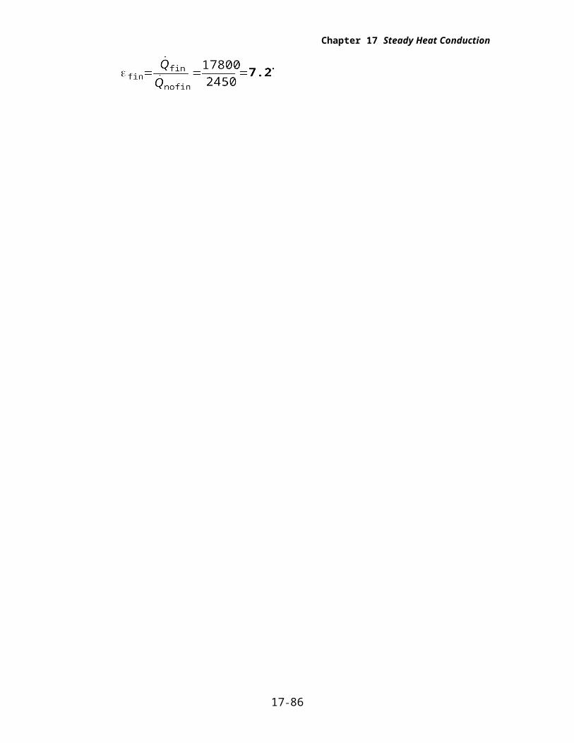
Then the fin effectiveness becomes
17-80
3 cm0.
6 cm
D=
0.2
5 cm
Chapter 17 Steady Heat Conduction
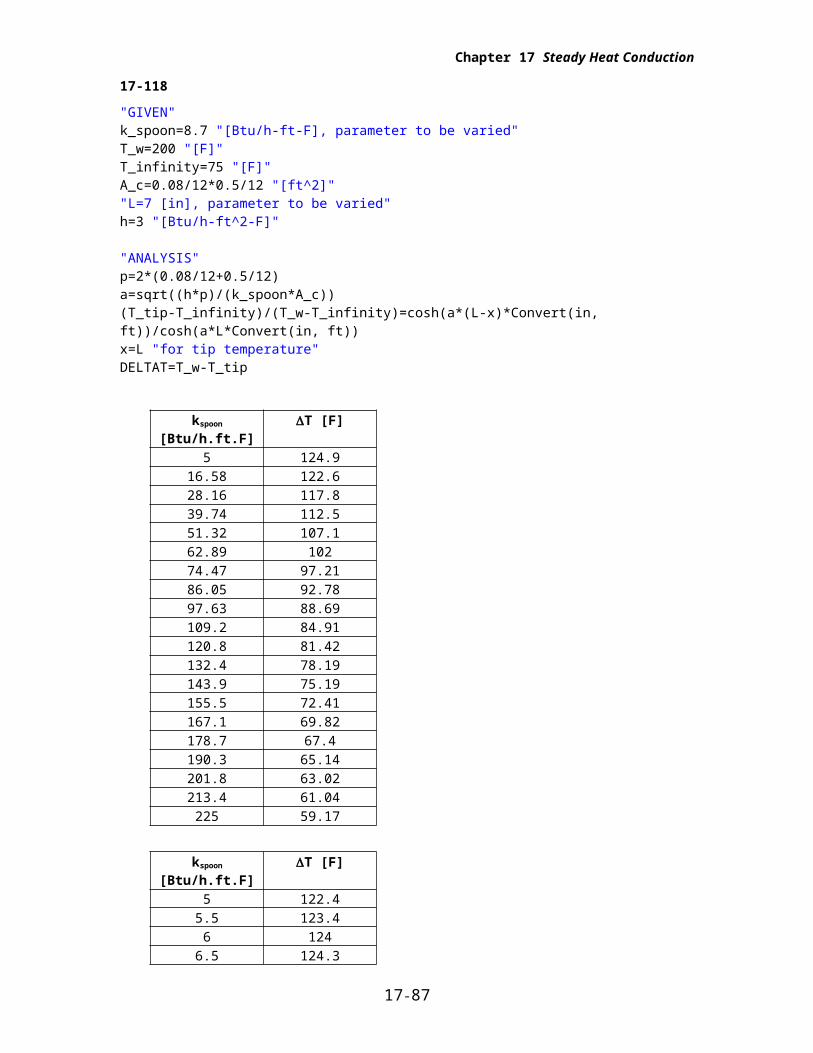
17-118
"GIVEN"k_spoon=8.7 "[Btu/h-ft-F], parameter to be varied"T_w=200 "[F]"T_infinity=75 "[F]"A_c=0.08/12*0.5/12 "[ft^2]""L=7 [in], parameter to be varied"h=3 "[Btu/h-ft^2-F]"
"ANALYSIS"p=2*(0.08/12+0.5/12)a=sqrt((h*p)/(k_spoon*A_c))(T_tip-T_infinity)/(T_w-T_infinity)=cosh(a*(L-x)*Convert(in, ft))/cosh(a*L*Convert(in, ft))x=L "for tip temperature"DELTAT=T_w-T_tip
kspoon [Btu/h.ft.F] T [F]5 124.9
16.58 122.628.16 117.839.74 112.551.32 107.162.89 10274.47 97.2186.05 92.7897.63 88.69109.2 84.91120.8 81.42132.4 78.19143.9 75.19155.5 72.41167.1 69.82178.7 67.4190.3 65.14201.8 63.02213.4 61.04225 59.17
kspoon [Btu/h.ft.F] T [F]5 122.4
5.5 123.46 124
6.5 124.37 124.6
7.5 124.78 124.8
8.5 124.99 124.9
9.5 12510 125
10.5 12511 125
11.5 125
17-81
Chapter 17 Steady Heat Conduction
12 125
0 45 90 135 180 22550
60
70
80
90
100
110
120
130
kspoon [Btu/h-ft-F]
T [
F]
5 6 7 8 9 10 11 12122
122.5
123
123.5
124
124.5
125
125.5
L [in]
T [
F]
17-82
Chapter 17 Steady Heat Conduction
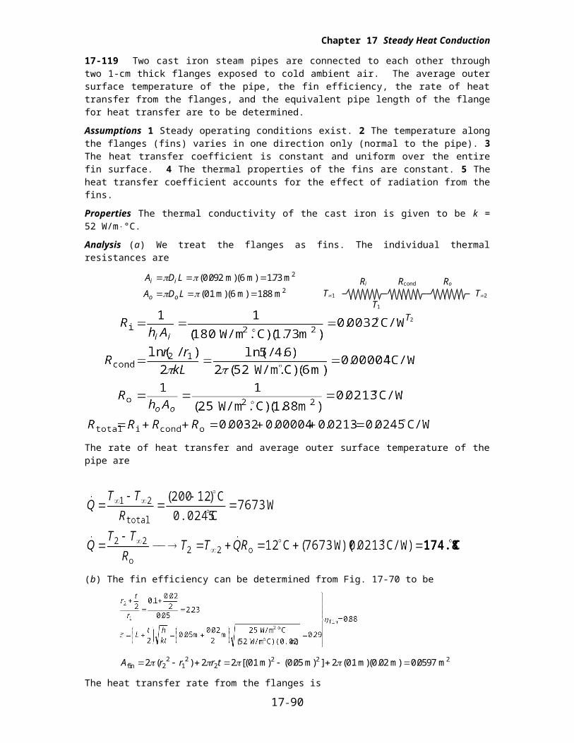
17-119 Two cast iron steam pipes are connected to each other through two 1-cm thick flanges exposed to cold ambient air. The average outer surface temperature of the pipe, the fin efficiency, the rate of heat transfer from the flanges, and the equivalent pipe length of the flange for heat transfer are to be determined.
Assumptions 1 Steady operating conditions exist. 2 The temperature along the flanges (fins) varies in one direction only (normal to the pipe). 3 The heat transfer coefficient is constant and uniform over the entire fin surface. 4 The thermal properties of the fins are constant. 5 The heat transfer coefficient accounts for the effect of radiation from the fins.
Properties The thermal conductivity of the cast iron is given to be k = 52 W/m°C.
Analysis (a) We treat the flanges as fins. The individual thermal resistances are
A D L
A D L
i i
o o
( . ( .
( . ( .
0 092 6 173
01 6 188
m) m) m
m) m) m
2
2
The rate of heat transfer and average outer surface temperature of the pipe are
(b) The fin efficiency can be determined from Fig. 17-70 to be
A r r r tfin2 2 2 m) m) m)(0.02 m) m 2 2 2 01 0 05 2 01 0 05972
21
22 ( ) [( . ( . ] ( . .
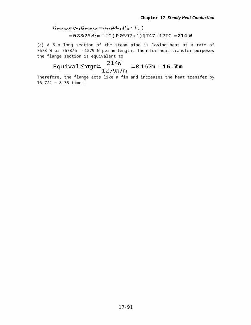
The heat transfer rate from the flanges is
(c) A 6-m long section of the steam pipe is losing heat at a rate of 7673 W or 7673/6 = 1279 W per m length. Then for heat transfer purposes the flange section is equivalent to
Therefore, the flange acts like a fin and increases the heat transfer by 16.7/2 = 8.35 times.
17-83
Ri Rcond Ro
T1 T2
T1 T2
Chapter 17 Steady Heat Conduction
Heat Transfer In Common Configurations
17-120C Under steady conditions, the rate of heat transfer between two surfaces is expressed as ( )Q Sk T T 1 2 where S is the conduction shape factor. It is related to the thermal resistance by
S=1/(kR).
17-121C It provides an easy way of calculating the steady rate of heat transfer between two isothermal surfaces in common configurations.
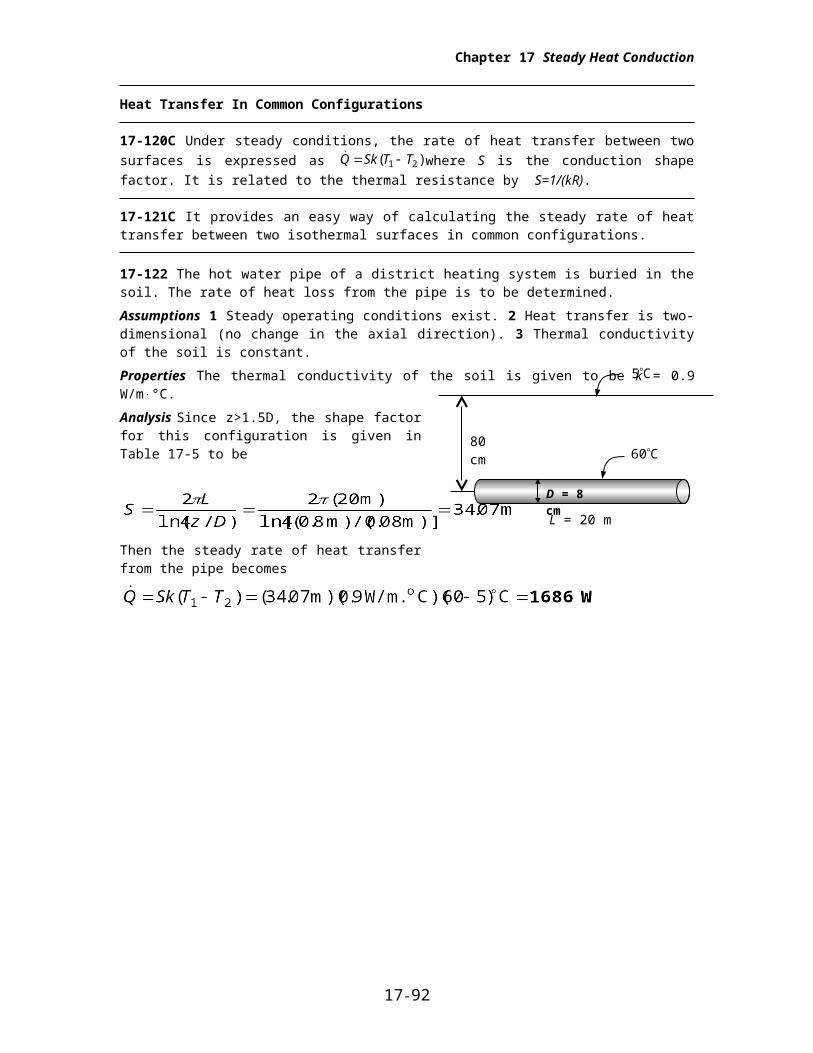
17-122 The hot water pipe of a district heating system is buried in the soil. The rate of heat loss from the pipe is to be determined.
Assumptions 1 Steady operating conditions exist. 2 Heat transfer is two-dimensional (no change in the axial direction). 3 Thermal conductivity of the soil is constant.
Properties The thermal conductivity of the soil is given to be k = 0.9 W/m°C.
Analysis Since z>1.5D, the shape factor for this configuration is given in Table 17-5 to be
Then the steady rate of heat transfer from the pipe becomes
17-84
60C
L = 20 m
D = 8 cm
5C
80 cm

Chapter 17 Steady Heat Conduction
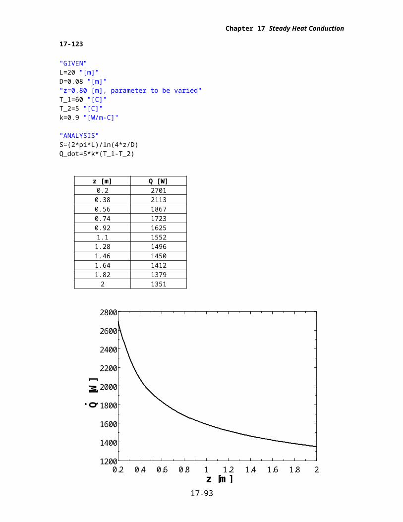
17-123
"GIVEN"L=20 "[m]"D=0.08 "[m]""z=0.80 [m], parameter to be varied"T_1=60 "[C]"T_2=5 "[C]"k=0.9 "[W/m-C]"
"ANALYSIS"S=(2*pi*L)/ln(4*z/D)Q_dot=S*k*(T_1-T_2)
z [m] Q [W]0.2 2701
0.38 21130.56 18670.74 17230.92 16251.1 1552
1.28 14961.46 14501.64 14121.82 1379
2 1351
0.2 0.4 0.6 0.8 1 1.2 1.4 1.6 1.8 21200
1400
1600
1800
2000
2200
2400
2600
2800
z [m]
Q [
W]
17-85
Chapter 17 Steady Heat Conduction
17-124 Hot and cold water pipes run parallel to each other in a thick concrete layer. The rate of heat transfer between the pipes is to be determined.
Assumptions 1 Steady operating conditions exist. 2 Heat transfer is two-dimensional (no change in the axial direction). 3 Thermal conductivity of the concrete is constant.
Properties The thermal conductivity of concrete is given to be k = 0.75 W/m°C.
Analysis The shape factor for this configuration is given in Table 17-5 to be
Then the steady rate of heat transfer between the pipes becomes
17-86
T2 = 15C
D = 5 cm
T1 = 60C
L = 8 mz = 40 cm
Chapter 17 Steady Heat Conduction
17-125
"GIVEN"L=8 "[m]"D_1=0.05 "[m]"D_2=D_1"z=0.40 [m], parameter to be varied"T_1=60 "[C]"T_2=15 "[C]"k=0.75 "[W/m-C]"
"ANALYSIS"S=(2*pi*L)/(arccosh((4*z^2-D_1^2-D_2^2)/(2*D_1*D_2)))Q_dot=S*k*(T_1-T_2)
z [m] Q [W]0.1 644.10.2 411.10.3 342.30.4 306.40.5 283.40.6 2670.7 254.70.8 244.80.9 236.81 230
0.1 0.2 0.3 0.4 0.5 0.6 0.7 0.8 0.9 1200
250
300
350
400
450
500
550
600
650
z [m]
Q [
W]
17-87
Chapter 17 Steady Heat Conduction
17-126E A row of used uranium fuel rods are buried in the ground parallel to each other. The rate of heat transfer from the fuel rods to the atmosphere through the soil is to be determined.
Assumptions 1 Steady operating conditions exist. 2 Heat transfer is two-dimensional (no change in the axial direction). 3 Thermal conductivity of the soil is constant.
Properties The thermal conductivity of the soil is given to be k = 0.6 Btu/hft°F.
Analysis The shape factor for this configuration is given in Table 17-5 to be
Then the steady rate of heat transfer from the fuel rods becomes
17-127 Hot water flows through a 5-m long section of a thin walled hot water pipe that passes through the center of a 14-cm thick wall filled with fiberglass insulation. The rate of heat transfer from the pipe to the air in the rooms and the temperature drop of the hot water as it flows through the pipe are to be determined.
Assumptions 1 Steady operating conditions exist. 2 Heat transfer is two-dimensional (no change in the axial direction). 3 Thermal conductivity of the fiberglass insulation is constant. 4 The pipe is at the same temperature as the hot water.
Properties The thermal conductivity of fiberglass insulation is given to be k = 0.035 W/m°C.
Analysis (a)The shape factor for this configuration is given in Table 17-5 to be
Then the steady rate of heat transfer from the pipe becomes
( ) ( )( . )( )Q Sk T T 1 2 16 0 035 60 18 m W / m. C C 23.5 W
(b) Using the water properties at the room temperature, the temperature drop of the hot water as it flows through this 5-m section of the wall becomes
17-88
T2 = 60F
8 in
T1 = 350F
15 ft
D = 1 in
L = 3 ft
60C
L = 5 m
D =2.5 cm
18C

Chapter 17 Steady Heat Conduction
17-128 Hot water is flowing through a pipe that extends 2 m in the ambient air and continues in the ground before it enters the next building. The surface of the ground is covered with snow at 0 C. The total rate of heat loss from the hot water and the temperature drop of the hot water in the pipe are to be determined.
Assumptions 1 Steady operating conditions exist. 2 Heat transfer is two-dimensional (no change in the axial direction). 3 Thermal conductivity of the ground is constant. 4 The pipe is at the same temperature as the hot water.
Properties The thermal conductivity of the ground is given to be k = 1.5 W/m°C.
Analysis (a) We assume that the surface temperature of the tube is equal to the temperature of the water. Then the heat loss from the part of the tube that is on the ground is
Considering the shape factor, the heat loss for vertical part of the tube can be determined from
( ) ( . )( . )(80 )Q Sk T T 1 2 344 15 0 413 m W / m. C C W
The shape factor, and the rate of heat loss on the horizontal part that is in the ground are
( ) ( . )( . )(80 )Q Sk T T 1 2 22 9 15 0 2748 m W / m. C C W
and the total rate of heat loss from the hot water becomes
(b) Using the water properties at the room temperature, the temperature drop of the hot water as it flows through this 25-m section of the wall becomes
17-89
8C
3 m
80C
0C
20 m
Chapter 17 Steady Heat Conduction
17-129 The walls and the roof of the house are made of 20-cm thick concrete, and the inner and outer surfaces of the house are maintained at specified temperatures. The rate of heat loss from the house through its walls and the roof is to be determined, and the error involved in ignoring the edge and corner effects is to be assessed.
Assumptions 1 Steady operating conditions exist. 2 Heat transfer at the edges and corners is two-or three-dimensional. 3 Thermal conductivity of the concrete is constant. 4 The edge effects of adjoining surfaces on heat transfer are to be considered.
Properties The thermal conductivity of the concrete is given to be k = 0.75 W/m°C.
Analysis The rate of heat transfer excluding the edges and corners is first determined to be
Atotal2 m ( . )( . ) ( . )( . ) .12 0 4 12 0 4 4 12 0 4 6 0 2 4037
( )( . )( . )
.( ) ,Q
kA
LT T
total
2 W / m. C m
mC W1 2
0 75 4037
0 215 3 18 167
The heat transfer rate through the edges can be determined using the shape factor relations in Table 17-5,
and
Ignoring the edge effects of adjoining surfaces, the rate of heat transfer is determined from
Atotal2 m ( )( ) ( )( )12 12 4 12 6 432
The percentage error involved in ignoring the effects of the edges then becomes
17-130 The inner and outer surfaces of a long thick-walled concrete duct are maintained at specified temperatures. The rate of heat transfer through the walls of the duct is to be determined.
Assumptions 1 Steady operating conditions exist. 2 Heat transfer is two-dimensional (no change in the axial direction). 3 Thermal conductivity of the concrete is constant.
Properties The thermal conductivity of concrete is given to be k = 0.75 W/m°C.
Analysis The shape factor for this configuration is given in Table 17-5 to be
Then the steady rate of heat transfer through the walls of the duct becomes
17-90
3C
15C
L
L
100C
15C
20 cm
16 cm
Chapter 17 Steady Heat Conduction
17-131 A spherical tank containing some radioactive material is buried in the ground. The tank and the ground surface are maintained at specified temperatures. The rate of heat transfer from the tank is to be determined.
Assumptions 1 Steady operating conditions exist. 2 Heat transfer is two-dimensional (no change in the axial direction). 3 Thermal conductivity of the ground is constant.
Properties The thermal conductivity of the ground is given to be k = 1.4 W/m°C.
Analysis The shape factor for this configuration is given in Table 17-5 to be
SD
D
z
2
1 0 25
2 3
1 0 253
55
2183
.
( )
..
. m
m
m
m
Then the steady rate of heat transfer from the tank becomes
17-91
T2 =15C
T1 = 140Cz = 5.5 m
D = 3 m
Chapter 17 Steady Heat Conduction
17-132
"GIVEN""D=3 [m], parameter to be varied"k=1.4 "[W/m-C]"h=4 "[m]"T_1=140 "[C]"T_2=15 "[C]"
"ANALYSIS"z=h+D/2S=(2*pi*D)/(1-0.25*D/z)Q_dot=S*k*(T_1-T_2)
D [m] Q [W]0.5 566.41 1164
1.5 17912 2443
2.5 31203 3820
3.5 45394 5278
4.5 60345 6807
0.5 1 1.5 2 2.5 3 3.5 4 4.5 50
1000
2000
3000
4000
5000
6000
7000
D [m]
Q [
W]
17-92
Chapter 17 Steady Heat Conduction
17-133 Hot water passes through a row of 8 parallel pipes placed vertically in the middle of a concrete wall whose surfaces are exposed to a medium at 20 with a heat transfer coefficient of 8 W/m2.C. The rate of heat loss from the hot water, and the surface temperature of the wall are to be determined.
Assumptions 1 Steady operating conditions exist. 2 Heat transfer is two-dimensional (no change in the axial direction). 3 Thermal conductivity of concrete is constant.
Properties The thermal conductivity of concrete is given to be k = 0.75 W/m°C.
Analysis The shape factor for this configuration is given in Table 17-5 to be
Then rate of heat loss from the hot water in 8 parallel pipes becomes
The surface temperature of the wall can be determined from
17-93
85C
L = 4 m
D
32C
z
z