ftx232h mpsse i2c master example in c# - ftdichip.com · application note an_411 ftx232h mpsse i2c...
TRANSCRIPT

Use of FTDI devices in life support and/or safety applications is entirely at the user’s risk, and the user
agrees to defend, indemnify and hold FTDI harmless from any and all damages, claims, suits or expense resulting from such use.
Future Technology Devices International Limited (FTDI) Unit 1, 2 Seaward Place, Glasgow G41 1HH, United Kingdom Tel.: +44 (0) 141 429 2777 Fax: + 44 (0) 141 429 2758
Web Site: http://ftdichip.com Copyright © Future Technology Devices International Limited
Application Note
AN_411
FTx232H MPSSE I2C Master Example
in C#
Version 1.0
Issue Date: 2017-05-17
This application note shows an example of using the MPSSE feature of the FT232H, FT2232H and FT4232H devices to create a USB to I2C Master device with a C# Visual Studio project.
Application Note
AN_411 FTx232H MPSSE I2C Master Example in C# Version 1.0
Document Reference No.: FT_001330 Clearance No.: FTDI#528
2 Product Page
Document Feedback Copyright © Future Technology Devices International Limited
Table of Contents
1 Introduction .................................................................... 4
2 Hardware ........................................................................ 5
2.1 Comparison of FT232H, FT2232H, FT4232H MPSSE Features .... 5
2.2 Hardware Description ............................................................... 6
2.2.1 FTDI Module ............................................................................................. 7
2.2.2 Power ...................................................................................................... 7
2.2.3 Proximity Sensor (VCNL4010) ..................................................................... 7
2.2.4 Colour Sensor (TCS34725) ......................................................................... 7
2.2.5 GPIO ........................................................................................................ 8
2.2.6 I2C........................................................................................................... 8
2.2.7 EEPROM Settings ....................................................................................... 8
2.3 Prototype Hardware .................................................................. 8
3 Software ....................................................................... 10
3.1 Sample code package .............................................................. 10
4 Software - Application Code .......................................... 11
4.1 Form1_Load ............................................................................ 11
4.2 Button1_Click (Initialise button) ............................................ 11
4.3 Button2_Click (Start button) .................................................. 12
4.4 Button3_Click (Stop button) ................................................... 12
5 Software - Sensor Interface Functions .......................... 13
5.1 Proximity Sensor..................................................................... 13
5.1.1 Configuration (ProximitySensorConfig()) .................................................... 13
5.1.2 Reading (ProximitySensorReading()) ......................................................... 14
5.2 Colour Sensor ......................................................................... 16
5.2.1 Configuration (ColourSensorConfig())......................................................... 16
5.2.2 Reading (ColourSensorReading()) .............................................................. 16
6 Software - I2C Functions ............................................... 18
6.1 MPSSE Commands ................................................................... 18
6.2 Function Descriptions ............................................................. 19
6.2.1 I2C_ConfigureMpsse ................................................................................ 19
6.2.2 3-phase clock.......................................................................................... 19
6.2.3 Clock rate ............................................................................................... 20
Application Note
AN_411 FTx232H MPSSE I2C Master Example in C# Version 1.0
Document Reference No.: FT_001330 Clearance No.: FTDI#528
3 Product Page
Document Feedback Copyright © Future Technology Devices International Limited
6.2.4 Open Drain ............................................................................................. 21
6.2.5 I2C_SendByteAndCheckACK ..................................................................... 21
6.2.6 I2C_SendDeviceAddrAndCheckACK ............................................................ 22
6.2.7 I2C_ReadByte ......................................................................................... 23
6.2.8 I2C_Read2BytesWithAddr ......................................................................... 24
6.2.9 I2C_SetStart ........................................................................................... 25
6.2.10 I2C_SetStop ........................................................................................... 25
6.2.11 I2C_SetLineStatesIdle .............................................................................. 26
6.2.12 I2C_GetGPIOValuesLow ........................................................................... 26
6.2.13 I2C_SetGPIOValuesHigh (FT232H and FT2232H Only) .................................. 27
6.2.14 I2C_GetGPIOValuesHigh (FT232H and FT2232H Only) ................................. 27
7 Software - D2xx Driver and C# Wrapper ....................... 28
7.1.1 Send_Data ............................................................................................. 28
7.1.2 Receive_Data .......................................................................................... 29
7.1.3 FlushBuffer ............................................................................................. 30
7.1.4 Multiple Channels .................................................................................... 30
8 Further Development .................................................... 31
8.1 Other Languages ..................................................................... 31
8.2 Clock Stretching ...................................................................... 31
8.3 Hardware ................................................................................ 31
9 Using the Demo ............................................................. 32
10 Conclusion ..................................................................... 34
11 Contact Information ...................................................... 35
Appendix A - References .................................................... 36
Document References ..................................................................... 36
Acronyms and Abbreviations ........................................................... 37
Appendix B – List of Tables & Figures ................................ 38
List of Tables ................................................................................... 38
List of Figures ................................................................................. 38
Appendix C – Revision History ........................................... 39

Application Note
AN_411 FTx232H MPSSE I2C Master Example in C# Version 1.0
Document Reference No.: FT_001330 Clearance No.: FTDI#528
4 Product Page
Document Feedback Copyright © Future Technology Devices International Limited
1 Introduction
This application note shows an example of using the MPSSE feature of the FT232H, FT2232H and FT4232H devices as an I2C Master with a C# project.
It uses a proximity sensor and an RGB colour sensor as I2C peripherals and to create a system which can
detect the presence of an object in close proximity and can then determine its colour.
Figure 1 - Sensor hardware and application
The code itself is written in C# and uses the FTDI D2XX Drivers NET wrapper. It provides a graphical user
interface for displaying the sensor data, and contains functions to implement the I2C protocol and GPIO
via MPSSE. These can all be customised in order to tailor the application for different sensors and different ways of presenting the measured data.
The main components, consisting of the proximity sensor, colour sensor and FTDI FT232H / FT2232H / FT4232H are all available on development modules allowing the hardware to be prototyped very quickly and easily.
This application note demonstrates the following principles:
Using the FTDI D2XX Drivers with C# applications
Using the FT232H / FT2232H / FT4232H MPSSE to implement I2C Master protocol
Displaying the gathered data in a graphical user interface
Using the AD3:7 pins as GPIO (useful for C232HM cable applications where only ADBUS is accessible)
A big advantage of using MPSSE is that there is no firmware to develop, program and maintain. The
FT232H and FTx232H devices are hardware bridges supplied ready to use, with the MPSSE controlled entirely by commands from the PC. This means that any changes in functionality of the end product (such as to add features, read different registers in the I2C peripherals or add support for different I2C peripherals) can all be implemented with a new release of the application program running on the PC.

Application Note
AN_411 FTx232H MPSSE I2C Master Example in C# Version 1.0
Document Reference No.: FT_001330 Clearance No.: FTDI#528
5 Product Page
Document Feedback Copyright © Future Technology Devices International Limited
2 Hardware
2.1 Comparison of FT232H, FT2232H, FT4232H MPSSE Features
The software provided with this application note can be used on the FT232H, FT2232H and FT4232H. These devices all have very similar MPSSE feature sets. The following table highlights some features and differences relevant to the I2C implementation. Further details of the MPSSE commands and features can be found in AN_108 and AN_135 and in the datasheet of the selected FTx232H device.
Feature FT232H FT2232H FT4232H Notes
Total Ports on device 1 2 4
MPSSE capable ports 1 2 2
Open Drain capability Y N N
Three Phase Clocking Y Y Y Allows data to be stable on both clock edges as required for I2C (see section 6.2.1)
GPIO per I2C port (ADBUS/ACBUS)
5/8 5/8 5/0 No ACBUS on FT4232H
Default start up mode EE EE UART EE indicates that the device starts in the mode selected in EEPROM e.g. UART, FIFO
Table 1 - Features by device type
The device selection depends on the requirements of the application. If a single channel is required, the
FT232H’s open drain feature and the availability of up to 13 GPIO make it a good choice. If the application requires an additional SPI interface, another I2C bus, or a UART port, then the FT2232H allows this to be achieved with only one USB port. The FT4232H extends this by offering four ports including up to two MPSSE interfaces.
In terms of throughput, the MPSSE on all three devices will give very similar performance. One thing to consider however that is the USB protocol shares bandwidth across all devices connected. This applies to all devices connected to the same USB host controller (most PCs have just one host controller an internal
hub), and so even devices on another USB port of the PC can take bandwidth on the bus. The Bulk USB transfer mode used by the FTx232H devices is optimized for high throughput and error checking but does not offer guaranteed latencies. If the application is sensitive to latencies then it should be tested under the worst case conditions including OS latencies and USB bandwidth.
The MPSSE is always a Master and cannot implement an I2C slave interface. If USB to I2C slave conversion is needed (e.g. to connect an MCU which has an I2C Master to a PC over USB) then the FTDI
FT200XD/FT201X devices would be suitable. In addition, the MPSSE does not support multi-master I2C
operation.
Application Note
AN_411 FTx232H MPSSE I2C Master Example in C# Version 1.0
Document Reference No.: FT_001330 Clearance No.: FTDI#528
6 Product Page
Document Feedback Copyright © Future Technology Devices International Limited
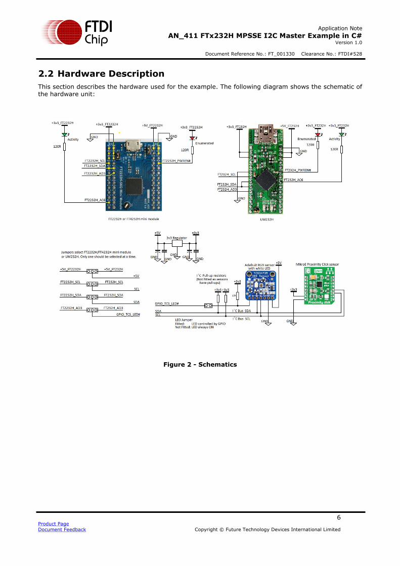
2.2 Hardware Description
This section describes the hardware used for the example. The following diagram shows the schematic of the hardware unit:
Figure 2 - Schematics

Application Note
AN_411 FTx232H MPSSE I2C Master Example in C# Version 1.0
Document Reference No.: FT_001330 Clearance No.: FTDI#528
7 Product Page
Document Feedback Copyright © Future Technology Devices International Limited
2.2.1 FTDI Module
The demo allows the use of any of the three devices FT232H, FT2232H or FT4232H via the following modules:
FT232H UM232H FT2232H FT2232H-56 Mini Module (or FT2232H Mini Module) FT4232H FT4232H-56 Mini Module (or FT4232H Mini Module)
These modules are designed by FTDI to allow easy evaluation of the devices and include all components needed for the device including the USB connector and external EEPROM.
A standard 28-pin wide IC socket is provided for a UM232H. Note that connections must be made to the VIO and 5V0 power pins before the module will be recognised by a PC.
A pair of dual-row header sockets is provided for the FT2232H or FT4232H mini modules. For the FT2232H and FT4232H, the 56Q version of the module was used as this has on-board jumpers to connect
VCC and VCCIO. The original module with 64-pin IC can be used in the same way provided the external connections are made to power up the module (see the module datasheet for details)
2.2.2 Power
A small regulator provides a stable 3v3 supply to the sensor modules derived from the USB 5V supply. Whilst all of the FTDI modules used in this application note have 3v3 out connections which can provide a small amount of current for external circuitry, an external LDO allows greater current capability which
may be required depending on the sensors used.
2.2.3 Proximity Sensor (VCNL4010)
The Proximity Click module from MikroElektronika was used which contains the VCNL4010 IC and
supporting components in an easy to use dual-in-line format. This sensor has a built-in IR emitter and PIN photodiode which allow it to determine the proximity of an object within a 20cm range. It has built-in processing which turns the amount of reflected light into a single 16-bit register value which represents
the distance of the object from the sensor. Additional registers allow configuration of the IR emitter current, averaging settings and other parameters. The sensor has I2C address 0x13 (in 7-bit address notation). More information can be found at the product page:
MikroElektronika Proximity click
2.2.4 Colour Sensor (TCS34725)
The colour sensor selected was the TCS34725 RGB colour sensor with IR filter and white LED, which is
available on a board from Adafruit. Like the proximity sensor, this board allows easy connection to the small SMD package sensor and has all of the supporting circuitry on-board. An on-board white LED illuminates the object and the sensor measures the reflected light through an IR filter which blocks IR
components of the light to produce a more accurate reading. The white LED is controlled via a MOSFET which is connected to a GPIO line on the MPSSE so that the bright light can be turned off until an object is in close proximity. The sensor requires the object to be very close (in practice, the demo requires within one or two centimetres) to get accurate readings. A real colour measuring application would use
the sensor under much more controlled conditions in order to get a more accurate reading, including the ambient lighting conditions and calibration. The sensor has I2C address 0x29 (in 7-bit address notation). More information can be found at the product page:
Adafruit Colour Sensor

Application Note
AN_411 FTx232H MPSSE I2C Master Example in C# Version 1.0
Document Reference No.: FT_001330 Clearance No.: FTDI#528
8 Product Page
Document Feedback Copyright © Future Technology Devices International Limited
2.2.5 GPIO
A GPIO line is used to control the white LED on the colour sensor module. A second line is used as an activity indicator and turns on when the PC application configures the MPSSE. It toggles on each reading to indicate that the demo is actively polling the sensors. Both GPIO lines use the ADBUS as this is available on all three FTDI devices including the FT4232H and on cables such as C232HM which allow connection to ADBUS only.
The ACBUS lines (not available on FT4232H or C232HM) are also available for GPIO purposes, where AC7:0 provide up to 8 additional I/Os. It is therefore possible to have up to 13 GPIO lines in addition to the I2C lines.
2.2.6 I2C
For the I2C itself, the lines AD2:0 are used. AD0 is the MPSSE’s clock out pin and is therefore connected
to the SCL line of the I2C bus. The MPSSE always generates the clock and as such is always the I2C
Master. It is not designed for multi-master operation.
For data, the MPSSE has two separate pins; ADBUS 1 is the Data Out pin and ADbus2 is the Data In pin. Since the I2C bus uses a single bi-directional data line, the data in and data out lines are connected together to allow data to be both written out and read in.
For the FT232H, the I2C libraries in the software application set the pin states to be output for AD0 (clock) and AD1 (data out) and to be an input for AD2 (data in). The FT232H has a drive-only-zero feature which allows any of AD7:0 and AC7:0 to be selected as open-drain.
For the FT2232H and FT4232H, the application includes additional GPIO writes to ADBUS which tristate the AD1 Data Out pin when the line is not being driven, to simulate an open-drain pin.
2.2.7 EEPROM Settings
It is recommended that the FTx232H device has a configuration EEPROM fitted. This allows several settings to be optimised for the application. FTDI modules such as UM232H, C232HM, and FTx232H Mini Modules have configuration EEPROMs fitted on-board. FTDI’s free FT_PROG software can be used to
change EEPROM settings over USB if required.
For the FT232H and FT2232H, it is recommended to set the port to FIFO mode. Provided that the RD# and SI/WU# lines on ACBUS are de-asserted (pulled high) by the hardware then the 8 ADBUS lines will begin as tristate when the device starts up. The device can enter MPSSE mode from either UART or FIFO but if set for UART mode, the ADBUS lines would drive out their idle UART states until the I2C_ConfigureMPSSE function is called. Note that even in FIFO mode, some ACBUS lines are driven (e.g. TxE#) and so this should be
considered when assigning ACBUS lines for GPIO purposes. Asynchronous FIFO pin assignments can be found in the device datasheet.
It is suggested that the VCP option be turned off in the EEPROM so that the port is not accidentally opened by the user in other COM port applications such as terminals. This ensures the port is available to be found by the sensor application.
With an EEPROM, the device description string and serial number can also be changed to allow easy identification of the device. For example, the code could open by the description “SensorDemo” and the EEPROM could be programmed with this description.
2.3 Prototype Hardware
The prototype hardware is shown in the figure below.

Application Note
AN_411 FTx232H MPSSE I2C Master Example in C# Version 1.0
Document Reference No.: FT_001330 Clearance No.: FTDI#528
9 Product Page
Document Feedback Copyright © Future Technology Devices International Limited
Figure 3 - Prototype Hardware

Application Note
AN_411 FTx232H MPSSE I2C Master Example in C# Version 1.0
Document Reference No.: FT_001330 Clearance No.: FTDI#528
10 Product Page
Document Feedback Copyright © Future Technology Devices International Limited
3 Software
The software is written in Visual Studio 2013 using C#. Later versions of Visual Studio should also upgrade the project when opening.
The code for this application note is arranged in four particular areas. These are discussed further in the
following sections.
Application code
The main application itself, which handles the user interface and calls the functions which configure and read the sensors.
Sensor Interface Functions
These functions utilise the generic I2C functions from the layer below to build up the I2C transactions needed to talk to the sensors.
I2C Functions
These functions form a generic I2C library. This allows them to be used for a variety of different applications. Their main purpose is to convert the I2C calls from the layers above into a series of
MPSSE commands which are in turn sent using the calls to the D2xx driver.
D2xx Driver and C# Wrapper
When programming in C#, a wrapper is needed to allow the application to call the D2xx functions in the FTDI driver. FTDI also have a VB wrapper and a similar application for I2C is presented in AN_355. C++ applications can call the functions directly as shown in AN_255 (FT232H only) and AN_113.
3.1 Sample code package
This application note is provided with the source code for the sensor application. It is important to set the
#define at the top of the code to configure the code for the device type being used. In particular, this defines whether the code uses open-drain capabilities (FT232H) or whether it simulates this with GPIO writes (FT2232H/FT4232H) and whether it uses the upper byte of GPIO (FT232H and FT2232H only).
//#define FT232H #define FT2232H //#define FT4232H
The application when running displays the device type for which it was compiled at the bottom-right of the window.
If the application is to be universal, an auto-detect can be added to select the device based on device
properties (e.g. device type and PID)
Note: This application is intended to demonstrate the MPSSE programming required to implement an I2C Master interface. Some error checking and handling have been implemented where possible without affecting readability of the MPSSE code. However, the code is not intended to reflect all best practices for Windows application programming such as error handling and GUI implementation and C# programming
techniques.
Both the main application and the library functions are intended to be used as the basis for further development and may require customisation to suit the particular application and I2C peripheral. The functions are not intended as a ready-made library to suit all applications without modification. This flexibility to customise the code at lower levels allows fine-tuning of the I2C routines to suit the intended application.
Application Note
AN_411 FTx232H MPSSE I2C Master Example in C# Version 1.0
Document Reference No.: FT_001330 Clearance No.: FTDI#528
11 Product Page
Document Feedback Copyright © Future Technology Devices International Limited
4 Software - Application Code
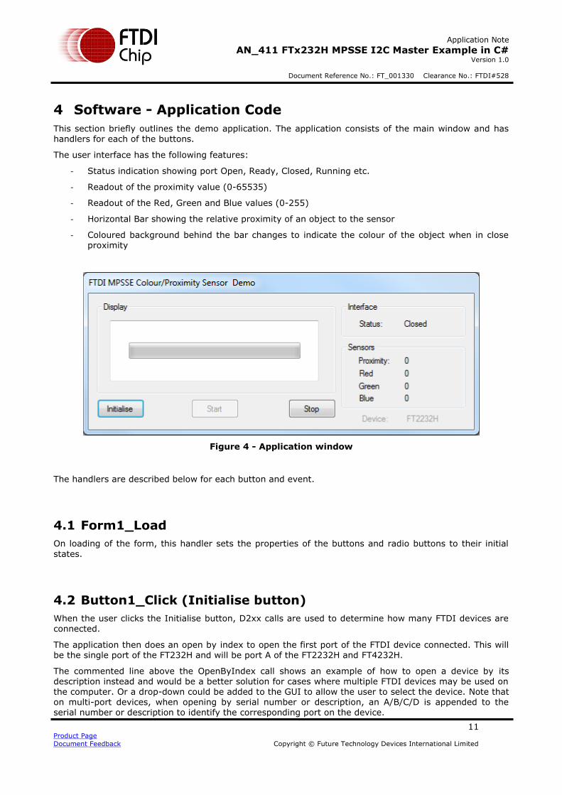
This section briefly outlines the demo application. The application consists of the main window and has handlers for each of the buttons.
The user interface has the following features:
- Status indication showing port Open, Ready, Closed, Running etc.
- Readout of the proximity value (0-65535)
- Readout of the Red, Green and Blue values (0-255)
- Horizontal Bar showing the relative proximity of an object to the sensor
- Coloured background behind the bar changes to indicate the colour of the object when in close proximity
Figure 4 - Application window
The handlers are described below for each button and event.
4.1 Form1_Load
On loading of the form, this handler sets the properties of the buttons and radio buttons to their initial
states.
4.2 Button1_Click (Initialise button)
When the user clicks the Initialise button, D2xx calls are used to determine how many FTDI devices are
connected.
The application then does an open by index to open the first port of the FTDI device connected. This will be the single port of the FT232H and will be port A of the FT2232H and FT4232H.
The commented line above the OpenByIndex call shows an example of how to open a device by its description instead and would be a better solution for cases where multiple FTDI devices may be used on the computer. Or a drop-down could be added to the GUI to allow the user to select the device. Note that on multi-port devices, when opening by serial number or description, an A/B/C/D is appended to the serial number or description to identify the corresponding port on the device.
Application Note
AN_411 FTx232H MPSSE I2C Master Example in C# Version 1.0
Document Reference No.: FT_001330 Clearance No.: FTDI#528
12 Product Page
Document Feedback Copyright © Future Technology Devices International Limited
Then, the I2C_ConfigureMPSSE function is called to set the device up for MPSSE operation.
On completion, the status LED on ACbus6 is illuminated by calling the I2C_SetGPIOValuesHigh function. This is only implemented for FT232H and FT2232H as the FT4232H does not have a high byte.
The functions ProximitySensorConfig and ColourSensorConfig are then called to set up the sensors over I2C.
4.3 Button2_Click (Start button)
When the user clicks the start button, the application enters a loop where it takes a reading from the proximity sensor. The call will return when the sensor has a reading available. This is then converted to a string which is displayed in the main application window. The reading will sit at a value of up to 2500 under ambient conditions with no item in close proximity.
The code then carries out some very basic processing on the data whereby if the reading is above a typical idle level (i.e. if an object does appear to be within range) a Log10 is applied. This was found in
practice to present a more linear relationship between object distance and bar graph value. The Log10 isn’t applied below 2500 as it amplifies small changes in background level when no object is nearby and makes the bar appear jittery.
If the proximity is greater than 10,000 (which correlates to the object being within a couple of cm of the sensor) it is now considered that the colour sensor becomes usable.
- A GPIO write is used to turn on the white illumination LED controlled by ADbus3. - The background colour of the application changes from a standard Windows ‘control light’ dialog
box background colour to instead represent the RGB data from the colour sensor.
The ColourSensorReading function is called to retrieve the RGB values from the sensor and these are used to update the colour of the background in the application window and to display the RGB values in the window.
On the FT232H and FT2232H, the GPIO line AC6 is toggled low and high again to blink the LED to indicate activity.
The loop continues whilst the variable ‘Running’ is true.
4.4 Button3_Click (Stop button)
The Stop button will set the variable ‘Running’ to false so that the sensor reading stops.
It calls myFtdiDevice.Close(); to close the port of the FTDI device and then closes the application itself.

Application Note
AN_411 FTx232H MPSSE I2C Master Example in C# Version 1.0
Document Reference No.: FT_001330 Clearance No.: FTDI#528
13 Product Page
Document Feedback Copyright © Future Technology Devices International Limited
5 Software - Sensor Interface Functions
The sensor interface functions handle the configuration and reading of the sensors. This section summarises each function.
As demonstrated by the proximity and colour examples here, most I2C sensors will use the same basic
sequence of I2C operations to write and read their registers and so the code can be adjusted easily to work with many other sensors. It is however important to consult the datasheet of the chosen I2C peripheral to confirm the protocol for writes and reads and for details of which registers it has available and what configuration is needed.
5.1 Proximity Sensor
The proximity sensor uses the I2C transactions shown below for writing and reading.
Figure 5 - I2C transfers for Proximity sensor
5.1.1 Configuration (ProximitySensorConfig())
This sample code carries out a basic configuration of the proximity sensor. The same technique can be used to configure the device to use all of its features. Details of the full feature set and registers can be
found in the datasheet.
An example of writing the current register is shown below. This also serves as a general example of writing registers in an I2C device using the library functions provided with this application note.
// VCNL_WrSingle(REGISTER_PROX_CURRENT, 20); AppStatus = I2C_SetStart(); // I2C START
if (AppStatus != 0) return 1; AppStatus = I2C_SendDeviceAddrAndCheckACK((byte)(VCNL40x0_ADDRESS), false); // SEND ADDR (WR)
if (AppStatus != 0) return 1; if (I2C_Ack != true) { I2C_SetStop(); return 1; }
AppStatus = I2C_SendByteAndCheckACK((byte)(REGISTER_PROX_CURRENT)); // SEND REGID if (AppStatus != 0) return 1; if (I2C_Ack != true) { I2C_SetStop(); return 1; } AppStatus = I2C_SendByteAndCheckACK((byte)(20)); // SEND VALUE if (AppStatus != 0) return 1; if (I2C_Ack != true) { I2C_SetStop(); return 1; } AppStatus = I2C_SetStop(); // I2C STOP
if (AppStatus != 0) return 1;
Note: Repeat Start is also allowed instead of the Stop and Start between the writing of the register and the reading of the value
Application Note
AN_411 FTx232H MPSSE I2C Master Example in C# Version 1.0
Document Reference No.: FT_001330 Clearance No.: FTDI#528
14 Product Page
Document Feedback Copyright © Future Technology Devices International Limited
An I2C start condition is first sent to the bus.
- If the writing of the commands to create the start condition failed (if AppStatus != 0) then this function returns with an error code 1.
Then, the device address is written to the I2C bus. The call includes the 7 bit address of the desired sensor on the bus and Boolean value false to indicate that this is the beginning of a write transaction.
- If the sending of the MPSSE commands failed, and so AppStatus != 0, then this function returns with an error code 1.
- If the call succeeded but the sensor didn’t acknowledge the byte, a stop condition is sent and the
function returns with error code 1.
Another write transaction now sends the register index to which the value will be written. The same error checking is used to ensure that the command succeeded and that the sensor acknowledges the byte.
A third write transaction now sends the value to be written to the register specified above and performs the same error checking to ensure the sensor actually took the byte.
Finally, an I2C Stop puts the stop condition on the bus and frees up the bus for the next transaction.
5.1.2 Reading (ProximitySensorReading())
When reading the proximity sensor, the first step is to check the Config register in the sensor to determine if a valid reading is ready. In this application, it was decided to poll the sensor in a while loop until a reading was available.
As shown in Figure 5 the read transaction begins with an I2C Start followed by an I2C write of the sensor’s address with the write bit set. The following byte written then specifies which register in the sensor is to be read (REGISTER_COMMAND in this case).
A repeat start (via I2C_SetStart) is then sent which begins the transaction to read the data from the previously specified register in the sensor, without giving up control of the bus.
The sensor’s I2C address is then sent again but with the read bit set, to indicate that this is a read
transaction. As with any write, it is recommended to check both the success of the call and that the sensors acknowledged the address phase before proceeding.
A call to I2C_ReadByte then clocks in a byte from the sensor which is the value from the register
addressed above. The parameter (false) causes the I2C library to clock out a NAK in response to the byte read, which tells the sensor that this is the last byte to read.
Finally, an I2C_SetStop call finished the transaction and frees up the I2C bus.
do { AppStatus = I2C_SetStart(); // I2C START if (AppStatus != 0) return 1; AppStatus = I2C_SendDeviceAddrAndCheckACK((byte)(VCNL40x0_ADDRESS), false); // SEND ADDR (WR) if (AppStatus != 0) return 1; if (I2C_Ack != true) { I2C_SetStop(); return 1; } AppStatus = I2C_SendByteAndCheckACK((byte)(REGISTER_COMMAND)); // REG ADDR if (AppStatus != 0) return 1; if (I2C_Ack != true) { I2C_SetStop(); return 1; } AppStatus = I2C_SetStart(); // RPT START if (AppStatus != 0) return 1; AppStatus = I2C_SendDeviceAddrAndCheckACK((byte)(VCNL40x0_ADDRESS), true); // SEND ADDR (RD) if (AppStatus != 0) return 1; if (I2C_Ack != true) { I2C_SetStop(); return 1; } AppStatus = I2C_ReadByte(false); // READ BYTE if (AppStatus != 0) return 1; Command = InputBuffer2[0]; AppStatus = I2C_SetStop(); // I2C STOP

Application Note
AN_411 FTx232H MPSSE I2C Master Example in C# Version 1.0
Document Reference No.: FT_001330 Clearance No.: FTDI#528
15 Product Page
Document Feedback Copyright © Future Technology Devices International Limited
if (AppStatus != 0) return 1;
} while ((Command & (COMMAND_MASK_PROX_DATA_READY)) == 0);
Once the PROX_DATA_READY bit is found to be set, the function can proceed to carry out a similar read transaction to obtain the proximity values from the results registers. The main difference is that since this is a 16-bit value, I2C_ReadByte is called twice in succession. The first call sends an ACK to the sensor (true) to tell it that more bytes will be read and the second call responds with a NAK telling the sensor that no more bytes are being read.
AppStatus = I2C_SetStart(); if (AppStatus != 0) return 1; AppStatus = I2C_SendDeviceAddrAndCheckACK((byte)(VCNL40x0_ADDRESS), false); if (AppStatus != 0) return 1; if (I2C_Ack != true) { I2C_SetStop(); return 1; } AppStatus = I2C_SendByteAndCheckACK((byte)(REGISTER_PROX_VALUE)); if (AppStatus != 0) return 1;
if (I2C_Ack != true) { I2C_SetStop(); return 1; } AppStatus = I2C_SetStart(); if (AppStatus != 0) return 1; AppStatus = I2C_SendDeviceAddrAndCheckACK((byte)(VCNL40x0_ADDRESS), true); if (AppStatus != 0) return 1; if (I2C_Ack != true) { I2C_SetStop(); return 1; } AppStatus = I2C_ReadByte(true); if (AppStatus != 0) return 1; ProxData[0] = InputBuffer2[0]; AppStatus = I2C_ReadByte(false); if (AppStatus != 0) return 1; ProxData[1] = InputBuffer2[0]; AppStatus = I2C_SetStop(); if (AppStatus != 0) return 1;
ProxiValue = (UInt16)((ProxData[0] << 8) | ProxData[1]);
Note that the calls highlighted above could be replaced with a combined function which sends the address and reads the two bytes (see I2C_Read2BytesWithAddr). Likewise, new I2C functions could be created to customize and optimize the communication even further (e.g. to include the I2C start, address, reading of n bytes and then I2C stop).
Application Note
AN_411 FTx232H MPSSE I2C Master Example in C# Version 1.0
Document Reference No.: FT_001330 Clearance No.: FTDI#528
16 Product Page
Document Feedback Copyright © Future Technology Devices International Limited
5.2 Colour Sensor
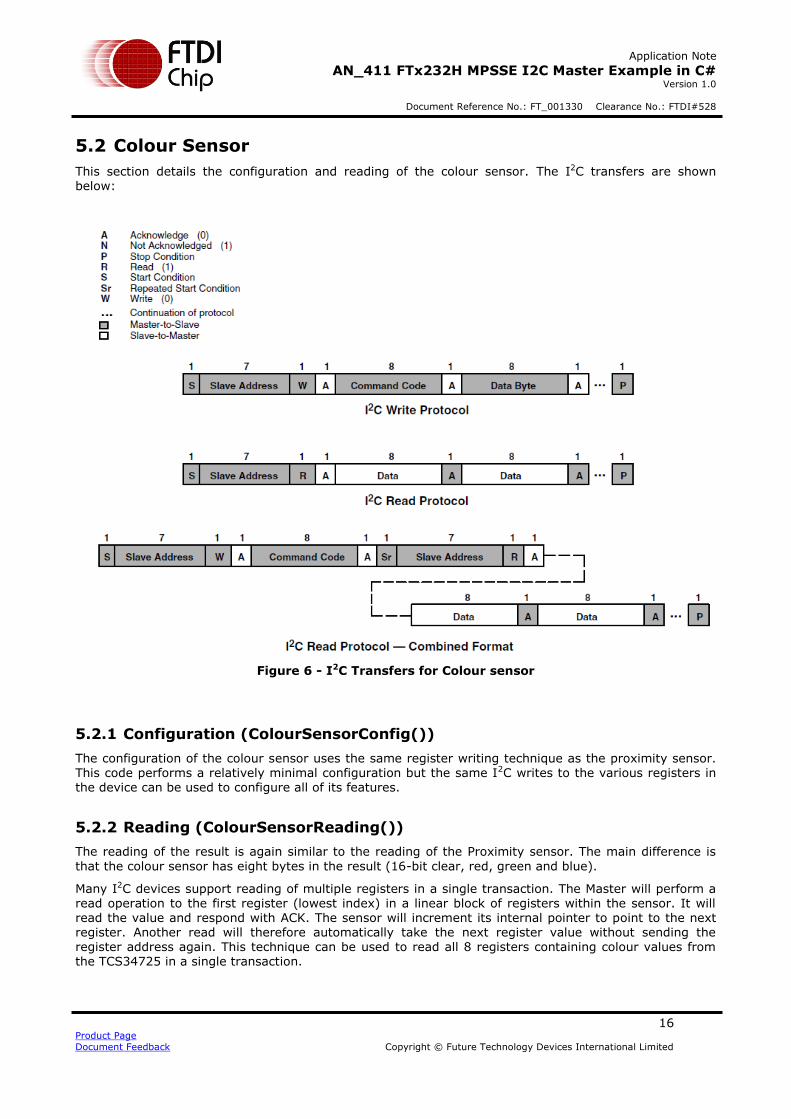
This section details the configuration and reading of the colour sensor. The I2C transfers are shown below:
Figure 6 - I2C Transfers for Colour sensor
5.2.1 Configuration (ColourSensorConfig())
The configuration of the colour sensor uses the same register writing technique as the proximity sensor. This code performs a relatively minimal configuration but the same I2C writes to the various registers in the device can be used to configure all of its features.
5.2.2 Reading (ColourSensorReading())
The reading of the result is again similar to the reading of the Proximity sensor. The main difference is
that the colour sensor has eight bytes in the result (16-bit clear, red, green and blue).
Many I2C devices support reading of multiple registers in a single transaction. The Master will perform a read operation to the first register (lowest index) in a linear block of registers within the sensor. It will read the value and respond with ACK. The sensor will increment its internal pointer to point to the next register. Another read will therefore automatically take the next register value without sending the register address again. This technique can be used to read all 8 registers containing colour values from the TCS34725 in a single transaction.
Application Note
AN_411 FTx232H MPSSE I2C Master Example in C# Version 1.0
Document Reference No.: FT_001330 Clearance No.: FTDI#528
17 Product Page
Document Feedback Copyright © Future Technology Devices International Limited
AppStatus = I2C_SetStart(); if (AppStatus != 0) return 1; AppStatus = I2C_SendDeviceAddrAndCheckACK((byte)(COLOR_ADDRESS), false); if (AppStatus != 0) return 1; if (I2C_Ack != true) { I2C_SetStop(); return 1; } AppStatus = I2C_SendByteAndCheckACK((byte)(0xB4)); // ID of the first register if (AppStatus != 0) return 1; if (I2C_Ack != true) { I2C_SetStop(); return 1; } AppStatus = I2C_SetStart(); if (AppStatus != 0) return 1; AppStatus = I2C_SendDeviceAddrAndCheckACK((byte)(COLOR_ADDRESS), true); if (AppStatus != 0) return 1; if (I2C_Ack != true) { I2C_SetStop(); return 1; } AppStatus = I2C_ReadByte(true); // Read byte and ACK if (AppStatus != 0) return 1; ClearColorSensorL = InputBuffer2[0]; AppStatus = I2C_ReadByte(true); // Read byte and ACK if (AppStatus != 0) return 1; ClearColorSensorH = InputBuffer2[0]; AppStatus = I2C_ReadByte(true); // Read byte and ACK if (AppStatus != 0) return 1; RedColorSensorL = InputBuffer2[0]; AppStatus = I2C_ReadByte(true); // Read byte and ACK if (AppStatus != 0) return 1; RedColorSensorH = InputBuffer2[0]; AppStatus = I2C_ReadByte(true); // Read byte and ACK if (AppStatus != 0) return 1; GreenColorSensorL = InputBuffer2[0]; AppStatus = I2C_ReadByte(true); // Read byte and ACK if (AppStatus != 0) return 1; GreenColorSensorH = InputBuffer2[0]; AppStatus = I2C_ReadByte(true); // Read byte and ACK if (AppStatus != 0) return 1; BlueColorSensorL = InputBuffer2[0]; AppStatus = I2C_ReadByte(false); // Read byte and NAK if (AppStatus != 0) return 1; BlueColorSensorH = InputBuffer2[0]; AppStatus = I2C_SetStop(); if (AppStatus != 0) return 1; ClearColorSensor = (ushort)((ClearColorSensorH * 256) | ClearColorSensorL); RedColorSensor = (ushort)((RedColorSensorH * 256) | RedColorSensorL); GreenColorSensor = (ushort)((GreenColorSensorH * 256) | GreenColorSensorL); BlueColorSensor = (ushort)((BlueColorSensorH * 256) | BlueColorSensorL);
One point to note is that the value from each read is stored in the corresponding variable (e.g. RedColorSensorL) since InputBuffer2[0] will be overwritten on the next call to I2C_ReadByte. These calls could be replaced with a combined address and read call following a similar principle to the function in
the I2C layer I2C_Read2BytesWithAddr.
Application Note
AN_411 FTx232H MPSSE I2C Master Example in C# Version 1.0
Document Reference No.: FT_001330 Clearance No.: FTDI#528
18 Product Page
Document Feedback Copyright © Future Technology Devices International Limited
6 Software - I2C Functions
The I2C functions provide the main application and sensor interface functions with a set of commands for the familiar I2C operations and create the required buffer of MPSSE commands which are sent to the chip in order to implement them on the I2C lines. By doing so, they avoid the layers above from needing to
know about the specifics of the MPSSE.
The following functions are provided within the example application:
I2C_ConfigureMpsse I2C_SendByteAndCheckACK I2C_SendDeviceAddrAndCheckACK I2C_ReadByte
I2C_Read2BytesWithAddr I2C_SetStart I2C_SetStop
I2C_SetLineStatesIdle I2C_GetGPIOValuesLow I2C_SetGPIOValuesHigh I2C_GetGPIOValuesHigh
Note that these functions are intended as a starting point for development of an application rather than a fixed library. They may need to be changed or additional ones created to suit the specific application and intended I2C Slave devices.
These functions use return code 0 to indicate success and a return code of 1 if an operation inside the function call failed. This could be extended to provide additional return codes if it is required to inform the calling function of the reason for failure.
This section uses the terminology I2C transaction to represent the time between I2C Start and I2C Stop i.e. the bus is busy.
Idle-within-transaction SCL held low and SDA released/floating
Idle-outwith-transaction SCL and SDA lines are both released/floating
6.1 MPSSE Commands
The application uses a combination of D2xx calls and MPSSE commands to configure the device and then to implement I2C communications.
The D2xx calls are commands direct to the chip hardware and/or driver. Examples include FT_SetFlowControl, FT_SetBitMode, FT_Read and FT_Write. In this application, they are made via the C# wrapper and so have the syntax myFtdiDevice.SetBitMode etc. (assuming the device was opened as myFtdiDevice) Please refer to the D2xx Programmers Guide. See Appendix A - References for the link to this document and also to the intellisense documentation provided by the xml file when including the FTD2XX_NET wrapper in the project.
The MPSSE commands are built up into a buffer/array by the application and sent to the chip via
a MyFtdiDevice.Write(…). The device must be put into MPSSE mode beforehand. The MPSSE engine in the device will then parses and execute these commands in the same sequence. Sending a buffer containing a series of GPIO commands and data clocking commands allows customized data transfers to be achieved and makes the MPSSE very flexible. Application note AN_108 details the command set of the MPSSE and AN_135 contains further
information on the MPSSE.
Application Note
AN_411 FTx232H MPSSE I2C Master Example in C# Version 1.0
Document Reference No.: FT_001330 Clearance No.: FTDI#528
19 Product Page
Document Feedback Copyright © Future Technology Devices International Limited
6.2 Function Descriptions
This section describes the provided I2C functions. The text below each table refers to the FT232H and then differences for the FT2232H/FT4232H are highlighted in blue text.
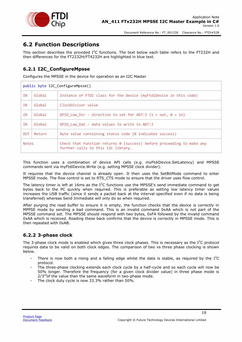
6.2.1 I2C_ConfigureMpsse
Configures the MPSSE in the device for operation as an I2C Master
public byte I2C_ConfigureMpsse()
IN Global Instance of FTDI class for the device (myFtdiDevice in this code)
IN Global ClockDivisor value
IN Global GPIO_Low_Dir – direction to set for AD7:3 (1 = out, 0 = in)
IN Global GPIO_Low_Dat – data values to write to AD7:3
OUT Return Byte value containing status code (0 indicates success)
Notes Check that function returns 0 (success) before proceeding to make any further calls to this I2C library.
This function uses a combination of device API calls (e.g. myFtdiDevice.SetLatency) and MPSSE commands sent via myFtdiDevice.Write (e.g. setting MPSSE clock divider).
It requires that the device channel is already open. It then uses the SetBitMode command to enter MPSSE mode. The flow control is set to RTS_CTS mode to ensure that the driver uses flow control.
The latency timer is left at 16ms as the I2C functions use the MPSSE’s send immediate command to get bytes back to the PC quickly when required. This is preferable as setting low latency timer values
increases the USB traffic (since it sends a packet back at the interval specified even if no data is being
transferred) whereas Send Immediate will only do so when required.
After purging the read buffer to ensure it is empty, the function checks that the device is correctly in MPPSE mode by sending a bad command. This is an invalid command 0xAA which is not part of the MPSSE command set. The MPSSE should respond with two bytes, 0xFA followed by the invalid command 0xAA which is received. Reading these back confirms that the device is correctly in MPSSE mode. This is then repeated with 0xAB.
6.2.2 3-phase clock
The 3-phase clock mode is enabled which gives three clock phases. This is necessary as the I2C protocol requires data to be valid on both clock edges. The comparison of two vs three phase clocking is shown below.
- There is now both a rising and a falling edge whilst the data is stable, as required by the I2C protocol.
- The three-phase clocking extends each clock cycle by a half-cycle and so each cycle will now be 50% longer. Therefore the frequency (for a given clock divider value) in three phase mode is 2/3rdof the value than the same waveform in two-phase mode.
- The clock duty cycle is now 33.3% rather than 50%.

Application Note
AN_411 FTx232H MPSSE I2C Master Example in C# Version 1.0
Document Reference No.: FT_001330 Clearance No.: FTDI#528
20 Product Page
Document Feedback Copyright © Future Technology Devices International Limited
Two-phase clocking: Clock Period: 6.5us, Clock Frequency: 153.846KHz, Duty Cycle 50%
Three-phase clocking: Clock Period: 10us, Clock Frequency: 100KHz, Duty Cycle 33.3%
Figure 7 - Three-Phase clocking
6.2.3 Clock rate
The clock divider is set to give the required I2C clock rate, which is created by dividing down the 60MHz clock which is supplied internally to the MPSSE. The divider calculation below is for a 400KHz I2C rate. 600KHz is used as the basis due to the actual rate being 1/3rd lower in three-phase clock mode.
MPSSE Clock Source = 60MHz
𝐶𝑙𝑜𝑐𝑘 𝑅𝑎𝑡𝑒 = 60𝑀𝐻𝑧
(1 + 𝐶𝐿𝑂𝐶𝐾𝐷𝐼𝑉𝐼𝐷𝐸𝑅) ∗ 2
600,000 = 60,000,000
(1 + 𝐶𝐿𝑂𝐶𝐾𝐷𝐼𝑉𝐼𝐷𝐸𝑅) ∗ 2
600,000 ∗ (1 + 𝐶𝐿𝑂𝐶𝐾𝐷𝐼𝑉𝐼𝐷𝐸𝑅) ∗ 2 = 60,000,000
1 + 𝐶𝐿𝑂𝐶𝐾𝐷𝐼𝑉𝐼𝐷𝐸𝑅 = 50
𝐶𝐿𝑂𝐶𝐾𝐷𝐼𝑉𝐼𝐷𝐸𝑅 = 49 (0𝑥31)
An optimised equation for three phase clock mode is:
𝐶𝑙𝑜𝑐𝑘 𝐷𝑖𝑣𝑖𝑠𝑜𝑟 = 30
(𝐶𝑙𝑜𝑐𝑘 𝑅𝑎𝑡𝑒 ∗ 1.5)− 1
Assuming Clock Rate in MHz, three-phase clocking enabled, and MPSSE divide-by-5 option disabled
Note: The Clock Divisor is always an integer and so some rates may need to be rounded to the nearest available value.
Application Note
AN_411 FTx232H MPSSE I2C Master Example in C# Version 1.0
Document Reference No.: FT_001330 Clearance No.: FTDI#528
21 Product Page
Document Feedback Copyright © Future Technology Devices International Limited
6.2.4 Open Drain
The I2C_SetLineStatesIdle function is then called to set the I2C lines to their idle states and will also apply the GPIO values to ADBUS required by the application (which can be set in global variables ADbusVal and ADBusDir before calling the I2C_ConfigureMPSSE function. A call could also be added here to set the high byte GPIO if desired.
The FT232H has a drive-only-zero feature which can be enabled individually on any of the 16 ACBUS and
ADBUS pins. This is effectively an open-drain mode for the selected pins and is again ideal for I2C where the lines are pulled down for logic 0 but released (pulled up by external resistors rather than driven high) for logic 1, thereby allowing many devices to share the same clock and data lines.
FT2232H/FT4232H: These devices don’t have open drain capability and so a GPIO write is used to simulate open drain by setting the data value low and the direction to input.
The function returns a status value where 0 indicates success. It would be possible to extend this to return additional error codes in the event that the function failed to allow the calling code to identify the
cause.
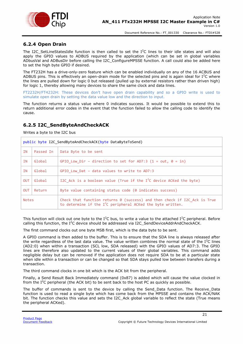
6.2.5 I2C_SendByteAndCheckACK
Writes a byte to the I2C bus
public byte I2C_SendByteAndCheckACK(byte DataByteToSend)
IN Passed In Data Byte to be sent
IN Global GPIO_Low_Dir – direction to set for AD7:3 (1 = out, 0 = in)
IN Global GPIO_Low_Dat – data values to write to AD7:3
OUT Global I2C_Ack is a boolean value (True if the I2C device ACKed the byte)
OUT Return Byte value containing status code (0 indicates success)
Notes Check that function returns 0 (success) and then check if I2C_Ack is True to determine if the I2C peripheral ACKed the byte written.
This function will clock out one byte to the I2C bus, to write a value to the attached I2C peripheral. Before calling this function, the I2C device should be addressed via I2C_SendDeviceAddrAndCheckACK.
The first command clocks out one byte MSB first, which is the data byte to be sent.
A GPIO command is then added to the buffer. This is to ensure that the SDA line is always released after
the write regardless of the last data value. The value written combines the normal state of the I2C lines (AD2:0) when within a transaction (SCL low, SDA released) with the GPIO values of AD7:3. The GPIO lines are therefore also updated to the current values of their global variables. This command adds negligible delay but can be removed if the application does not require SDA to be at a particular state when idle within a transaction or can be changed so that SDA stays pulled low between transfers during a transaction.
The third command clocks in one bit which is the ACK bit from the peripheral.
Finally, a Send Result Back Immediately command (0x87) is added which will cause the value clocked in from the I2C peripheral (the ACK bit) to be sent back to the host PC as quickly as possible.
The buffer of commands is sent to the device by calling the Send_Data function. The Receive_Data function is used to read a single byte which has come back from the MPSSE and contains the ACK/NAK bit. The function checks this value and sets the I2C_Ack global variable to reflect the state (True means the peripheral ACKed).

Application Note
AN_411 FTx232H MPSSE I2C Master Example in C# Version 1.0
Document Reference No.: FT_001330 Clearance No.: FTDI#528
22 Product Page
Document Feedback Copyright © Future Technology Devices International Limited
The function returns 0 if all calls for the writing of the commands and reading of the ACK bit succeeded.
It returns 1 if any of these failed. The code could be extended to return a wider range of error codes if desired.
FT2232H/FT4232H: Note that if the FT2232H or FT4232H are selected, additional GPIO writes are added to the MPSSE buffer which make the ADBUS bit 1 (data out) an output initially so that the data byte can be clocked out. It then puts the line back to an input to allow the attached I2C device to drive the line for the ACK bit.
6.2.6 I2C_SendDeviceAddrAndCheckACK
Sends an I2C address on the bus
public byte I2C_SendDeviceAddrAndCheckACK(byte Address, bool Read)
IN Passed In Address – I2C address of the device to be communicated with
IN Passed In Read – Booolean value specifying read (true) or write (false)
IN Global GPIO_Low_Dat – data values to write to AD7:3
IN Global GPIO_Low_Dir – direction to set for AD7:3 (1 = out, 0 = in)
OUT Global I2C_Ack is a boolean value (True if the I2C device ACKed the address)
OUT Return Byte value containing status code (0 indicates success)
Notes Check that function returns 0 (success) and then check if I2C_Ack is True to check if the I2C peripheral ACKed the address written.
This function is very similar to the I2C_SendByteAndCheckACK call discussed above but is specifically intended for addressing the I2C device.
Instead of taking the byte to write as a parameter, this modified function takes two parameters; a 7-bit I2C address (in the lower 7 bits) and a separate Boolean value defining whether to address the device for reading or writing.
Note that documentation for I2C peripheral devices may quote the I2C address in either the 7-bit or 8-bit
formats. E.g. some documentation and sample code may quote 7-bit address 0x40 whilst others may quote the write and read values as 0x80 and 0x81 respectively. This code is designed to accept the 7-bit value with the R/W bit specified separately.
It combines these into a single 8-bit value by shifting the 7-bit address one place left and OR’ing with the Read Boolean parameter, and sends this to the I2C bus. As with the I2C_SendByteAndCheckACK call, this function returns the ACK/NAK status via the global variable I2C_Ack.
FT2232H/FT4232H: Note that if the FT2232H or FT4232H are selected, additional GPIO writes are added
to the MPSSE buffer which make the ADBUS bit 1 (data out) an output initially so that the address byte can be clocked out. It then puts the line back to an input to allow the attached I2C device to drive the line
for the ACK bit.
Application Note
AN_411 FTx232H MPSSE I2C Master Example in C# Version 1.0
Document Reference No.: FT_001330 Clearance No.: FTDI#528
23 Product Page
Document Feedback Copyright © Future Technology Devices International Limited
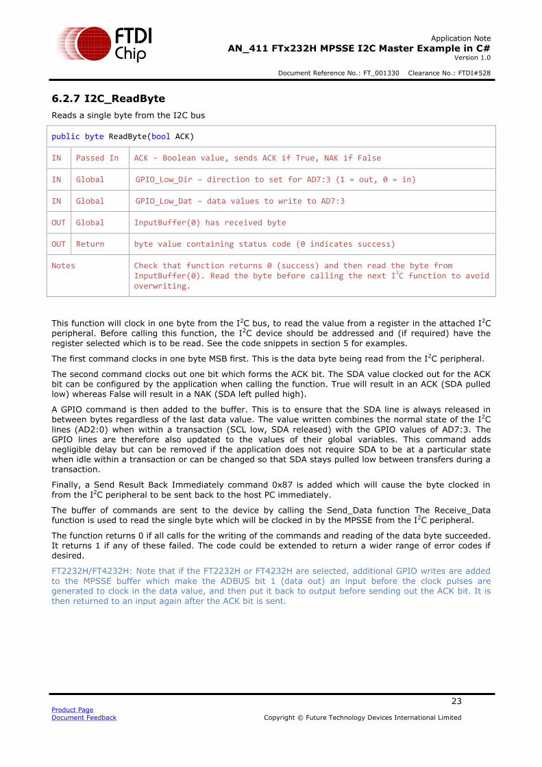
6.2.7 I2C_ReadByte
Reads a single byte from the I2C bus
public byte ReadByte(bool ACK)
IN Passed In ACK – Boolean value, sends ACK if True, NAK if False
IN Global GPIO_Low_Dir – direction to set for AD7:3 (1 = out, 0 = in)
IN Global GPIO_Low_Dat – data values to write to AD7:3
OUT Global InputBuffer(0) has received byte
OUT Return byte value containing status code (0 indicates success)
Notes Check that function returns 0 (success) and then read the byte from InputBuffer(0). Read the byte before calling the next I2C function to avoid overwriting.
This function will clock in one byte from the I2C bus, to read the value from a register in the attached I2C peripheral. Before calling this function, the I2C device should be addressed and (if required) have the
register selected which is to be read. See the code snippets in section 5 for examples.
The first command clocks in one byte MSB first. This is the data byte being read from the I2C peripheral.
The second command clocks out one bit which forms the ACK bit. The SDA value clocked out for the ACK bit can be configured by the application when calling the function. True will result in an ACK (SDA pulled low) whereas False will result in a NAK (SDA left pulled high).
A GPIO command is then added to the buffer. This is to ensure that the SDA line is always released in between bytes regardless of the last data value. The value written combines the normal state of the I2C
lines (AD2:0) when within a transaction (SCL low, SDA released) with the GPIO values of AD7:3. The GPIO lines are therefore also updated to the values of their global variables. This command adds negligible delay but can be removed if the application does not require SDA to be at a particular state when idle within a transaction or can be changed so that SDA stays pulled low between transfers during a transaction.
Finally, a Send Result Back Immediately command 0x87 is added which will cause the byte clocked in
from the I2C peripheral to be sent back to the host PC immediately.
The buffer of commands are sent to the device by calling the Send_Data function The Receive_Data function is used to read the single byte which will be clocked in by the MPSSE from the I2C peripheral.
The function returns 0 if all calls for the writing of the commands and reading of the data byte succeeded. It returns 1 if any of these failed. The code could be extended to return a wider range of error codes if desired.
FT2232H/FT4232H: Note that if the FT2232H or FT4232H are selected, additional GPIO writes are added
to the MPSSE buffer which make the ADBUS bit 1 (data out) an input before the clock pulses are generated to clock in the data value, and then put it back to output before sending out the ACK bit. It is
then returned to an input again after the ACK bit is sent.
Application Note
AN_411 FTx232H MPSSE I2C Master Example in C# Version 1.0
Document Reference No.: FT_001330 Clearance No.: FTDI#528
24 Product Page
Document Feedback Copyright © Future Technology Devices International Limited
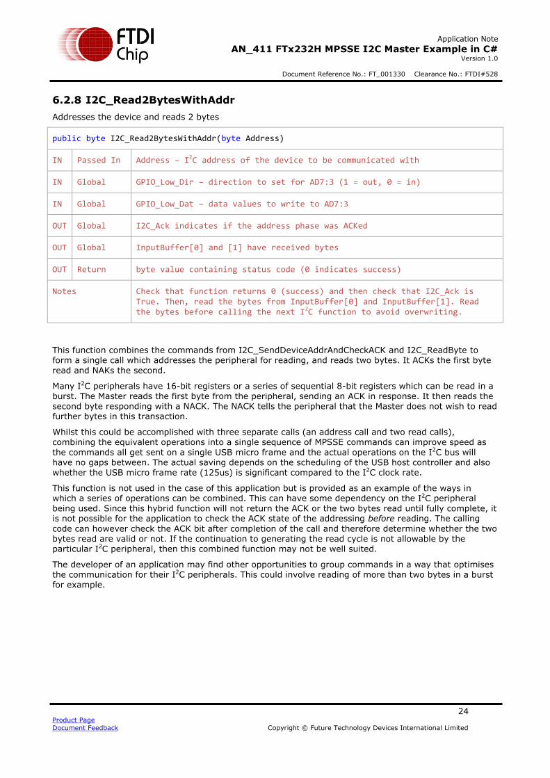
6.2.8 I2C_Read2BytesWithAddr
Addresses the device and reads 2 bytes
public byte I2C_Read2BytesWithAddr(byte Address)
IN Passed In Address – I2C address of the device to be communicated with
IN Global GPIO_Low_Dir – direction to set for AD7:3 (1 = out, 0 = in)
IN Global GPIO_Low_Dat – data values to write to AD7:3
OUT Global I2C_Ack indicates if the address phase was ACKed
OUT Global InputBuffer[0] and [1] have received bytes
OUT Return byte value containing status code (0 indicates success)
Notes Check that function returns 0 (success) and then check that I2C_Ack is True. Then, read the bytes from InputBuffer[0] and InputBuffer[1]. Read the bytes before calling the next I2C function to avoid overwriting.
This function combines the commands from I2C_SendDeviceAddrAndCheckACK and I2C_ReadByte to form a single call which addresses the peripheral for reading, and reads two bytes. It ACKs the first byte
read and NAKs the second.
Many I2C peripherals have 16-bit registers or a series of sequential 8-bit registers which can be read in a burst. The Master reads the first byte from the peripheral, sending an ACK in response. It then reads the second byte responding with a NACK. The NACK tells the peripheral that the Master does not wish to read further bytes in this transaction.
Whilst this could be accomplished with three separate calls (an address call and two read calls), combining the equivalent operations into a single sequence of MPSSE commands can improve speed as
the commands all get sent on a single USB micro frame and the actual operations on the I2C bus will have no gaps between. The actual saving depends on the scheduling of the USB host controller and also whether the USB micro frame rate (125us) is significant compared to the I2C clock rate.
This function is not used in the case of this application but is provided as an example of the ways in which a series of operations can be combined. This can have some dependency on the I2C peripheral being used. Since this hybrid function will not return the ACK or the two bytes read until fully complete, it is not possible for the application to check the ACK state of the addressing before reading. The calling
code can however check the ACK bit after completion of the call and therefore determine whether the two bytes read are valid or not. If the continuation to generating the read cycle is not allowable by the particular I2C peripheral, then this combined function may not be well suited.
The developer of an application may find other opportunities to group commands in a way that optimises the communication for their I2C peripherals. This could involve reading of more than two bytes in a burst for example.

Application Note
AN_411 FTx232H MPSSE I2C Master Example in C# Version 1.0
Document Reference No.: FT_001330 Clearance No.: FTDI#528
25 Product Page
Document Feedback Copyright © Future Technology Devices International Limited
6.2.9 I2C_SetStart
Sends the I2C Start condition
public byte I2C_SetStart()
IN Global GPIO_Low_Dir – direction to set for AD7:3 (1 = out, 0 = in)
IN Global GPIO_Low_Dat – data values to write to AD7:3
OUT Return byte value containing status code (0 indicates success)
Notes Check that function returns 0 (success)
This function will put the I2C Start condition onto the bus to begin an I2C transaction. The function can also be used as a repeat start which is used in transactions which read data from an I2C peripheral, in between writing to the device to select the register to be read and the actual reading operation.
The function builds a buffer of GPIO commands for the MPSSE, which it will work through in sequence. Each GPIO write is repeated six times to hold the associated pin state for a longer time.
Both SCK and SDA are initially high (open drain pulled up). The SDA line is brought low by putting ADbus1 low. Then, the SCL line is also brought low (ADbus0) to complete the sequence. The line is then left in the idle-during-transaction state which is SDA released and SCL held low. This could be easily changed if required by the applications.
FT2232H/FT4232H: These devices simulate an open-drain by keeping the data value low and using the
pin direction to release the line (pin set as input) or pull it low (pin set as output)
6.2.10 I2C_SetStop
Sends the I2C Stop condition
public byte I2C_SetStop()
IN Global GPIO_Low_Dir – direction to set for AD7:3 (1 = out, 0 = in)
IN Global GPIO_Low_Dat – data values to write to AD7:3
OUT Return byte value containing status code (0 indicates success)
Notes Check that function returns 0 (success)
This function will put the I2C Stop condition onto the bus, to end the I2C transaction on the bus.
The function builds a buffer of GPIO commands for the MPSSE which it will work through in sequence. Each GPIO write is repeated six times to hold the associated pin state for a longer time.
For the Stop condition, the SCL and SDA lines are pulled down initially. The SCL line is first brought high, followed by the SDA line. Both lines finish in the high (open drain) state.
FT2232H/FT4232H: These devices simulate an open-drain by keeping the data value low and using the pin direction to release the line (pin set as input) or pull it low (pin set as output)

Application Note
AN_411 FTx232H MPSSE I2C Master Example in C# Version 1.0
Document Reference No.: FT_001330 Clearance No.: FTDI#528
26 Product Page
Document Feedback Copyright © Future Technology Devices International Limited
6.2.11 I2C_SetLineStatesIdle
Sets the I2C lines to Idle Outwith Transaction and write ADbus GPIO
public byte I2C_SetLineStatesIdle()
IN Global GPIO_Low_Dir – direction to set for AD7:3 (1 = out, 0 = in)
IN Global GPIO_Low_Dat – data values to write to AD7:3
OUT Return byte value containing status code (0 indicates success)
Notes Check that function returns 0 (success). Do not call in the middle of an I2C transaction (i.e. between Start and Stop). This function is only for setting GPIO when no transaction is in progress.
The global variables containing the data and direction for AD7:3 are combined with the idle-outwith-transaction I2C pin states for ADbus2:0 (SCL and SDA both released) and this value is written via the 0x80 GPIO low commands. This masking is required since an MPSSE GPIO write command always writes all 8 bits of the port.
Since the use of this function would result in the SCL line being released, it is only intended for use when an I2C transaction isn’t in progress.
Note: The other I2C library calls for addressing, reading and writing will update the GPIO lines on ADbus
as part of their operation and so if a GPIO line on ADBUS requires to be changed during a transition, the associated global variables GPIO_Low_Dir and GPIO_Low_Dat can be written before the next I2C operation.
6.2.12 I2C_GetGPIOValuesLow
Gets the GPIO values of ADbus 7:3
public byte I2C_GetGPIOValuesLow()
OUT Global InputBuffer(0) has GPIO values in bits 7:3
OUT Return byte value containing status code (0 indicates success)
Notes Check that the function returns success. Then read the GPIO value from InputBuffer(0). The SetLineStatesIdle function must have been called at least once before in order to set the directions of the GPIO.
This function sends a GPIO low byte read command to the MPSSE along with a send-immediate command which causes the result to be returned immediately.
The resulting value is masked to zero the lower three bits, leaving the upper five bits reflecting the GPIO
value. The value can be read in bits 7:3 of the resulting byte via InputBuffer(0) after the function has been called.

Application Note
AN_411 FTx232H MPSSE I2C Master Example in C# Version 1.0
Document Reference No.: FT_001330 Clearance No.: FTDI#528
27 Product Page
Document Feedback Copyright © Future Technology Devices International Limited
6.2.13 I2C_SetGPIOValuesHigh (FT232H and FT2232H Only)
Sets the data and direction of ACbus bits 7 to 0
public byte I2C_SetGPIOValuesHigh(byte ACbusDir, byte ACbusVal)
IN Passed in ACbusDir contains the directions for the pins (1 = output)
IN Passed in ACbusVal contains the values to write to the pins which are outputs
OUT Return Byte value containing status code (0 indicates success)
Notes Check that the function returns success.
This function sends the 0x82 Write GPIO High Byte command followed by the value and direction bytes. This allows control of bits 7 to 0 of the ACBUS port. The values in parameter ACbusVal will be applied to pins which are configured as an output in the ACbusDir parameter (1 = output). This function can be
called any time after the MPSSE is initialised and does not affect the I2C lines.
FT232H: Note that the MPSSE can control and read only bits 0-7 of the ACBUS port. On the FT232H, the additional bits 8 and 9 are configurable in the EEPROM for other functions such as PWREN etc.
FT4232H: This function cannot be used as the FT4232H has only 8 bits per port and no upper byte.
6.2.14 I2C_GetGPIOValuesHigh (FT232H and FT2232H Only)
Read the values of ACbus bits 7 to 0.
public byte I2C_GetGPIOValuesHigh()
OUT Global InputBuffer(0) has GPIO values for this port
OUT Return Byte value containing status code (0 indicates success)
Notes Check that the function returns success.
This function sends the 0x83 Read GPIO High Byte command followed by a send-immediate opcode which causes the MPSSE to send the resulting byte back on the next available micro frame.
The return value should be checked to be 0 (success) and then the byte containing the pin values can be read via InputBuffer(0).
It is recommended to call I2C_SetGPIOValuesHigh at least once after initialisation before using the
GetGPIOValuesHigh. This ensures that the ACBUS pin directions are set as required for the application.
FT232H: Note that the MPSSE can control and read only bits 0-7 of the ACBUS port. On the FT232H, the additional bits 8 and 9 are configurable in the EEPROM for other functions such as PWREN etc.
FT4232H: This function cannot be used as the FT4232H has only 8 bits per port and no upper byte.

Application Note
AN_411 FTx232H MPSSE I2C Master Example in C# Version 1.0
Document Reference No.: FT_001330 Clearance No.: FTDI#528
28 Product Page
Document Feedback Copyright © Future Technology Devices International Limited
7 Software - D2xx Driver and C# Wrapper
Since effective use of the FT_Write and FT_Read D2xx calls involves some error checking and additional steps (such as checking the queue status before reading), the I2C library source provided here wraps these calls into functions Send_Data and Receive_Data. An additional call is used during initialisation to
flush any data in the driver’s buffer.
This application utilises the managed C# wrapper provided by FTDI and so the D2xx calls are made via the wrapper. The wrapper consists of a DLL for the wrapper itself FTD2XX_NET.DLL and an xml file FT22XX_NET.XML to provide intellisense help. The source code for the wrapper is also provided on the C# samples page. Further information on the wrapper and download details can be found at the page below:
http://www.ftdichip.com/Support/SoftwareExamples/CodeExamples/CSharp.htm
The sample code provided with this application note already includes a copy of these files.
7.1.1 Send_Data
Sends the requested number of bytes to the FTDI device
private byte Send_Data(uint BytesToSend)
IN Global Instance of FTDI device (in this example myFtdiDevice.)
IN Passed In BytesToSend – number of bytes to send
IN Global Data to send in SendBuffer(0) to SendBuffer(BytesToSend-1)
OUT Return Byte value containing status code (0 indicates success)
OUT Global BytesSent – number of bytes actually sent
Notes Check that function returns 0 (success) which means that all bytes were sent. If return is non-zero, bytes actually sent can be found in BytesSent
This function uses the FT_Write D2xx call (myFtdiDevice.Write) to send the data. The USB host in the PC will determine how and when the data is sent but from the application’s point of view the data will be sent as quickly as possible. The call blocks until complete and so setting a timeout with FT_SetTimeouts (e.g. 5 seconds as this is only a safety measure) is strongly recommended.

Application Note
AN_411 FTx232H MPSSE I2C Master Example in C# Version 1.0
Document Reference No.: FT_001330 Clearance No.: FTDI#528
29 Product Page
Document Feedback Copyright © Future Technology Devices International Limited
7.1.2 Receive_Data
Reads the requested number of bytes from the driver
private byte Receive_Data(uint BytesToRead)
IN Global Instance of FTDI device (in this example myFtdiDevice.)
IN Passed In BytesToRead – number of bytes to read
OUT Return byte value containing status code (0 indicates success)
OUT Global BytesRead – number of bytes actually read
OUT Global Data read in ReceiveBuffer(0) to ReceiveBuffer(BytesRead-1)
Notes Check that function returns 0 (success) which means that requested number of bytes were read. If return is non-zero, bytes actually read can be found in BytesRead
This function reads the data from the driver buffer after using the D2xx FT_GetQueueStatus (myFtdiDevice.GetRxBytesAvailable) to check how much data is available. When the MPSSE clocks in data or reads a byte from the GPIO of the chip, it will buffer the data on-chip. This data will be sent back to the PC when the buffer has enough data for a USB frame (510 bytes of data) or if the latency timer ticks over (16ms default), or if a Send Immediate command is executed by the MPSSE. This library uses the send immediate opcode after any operation involving clock in or GPIO read and so this will be the normal mechanism used in this case. The driver issues IN requests over USB to the device and the chip
will put the data into the IN packet when one of the aforementioned conditions occurs. The driver will buffer up this data and make it available for the application to read.
The Queue Status allows the application to check how much is currently buffered in the driver. This is especially useful as the FT_Read (myFtdiDevice.Read) is a blocking call and so it is best to read only data that is known to be available and so in theory a timeout should never occur. It is strongly recommended
to set a read timeout (e.g. 5 seconds) via FT_SetTimeouts as a safety measure however.
This function works by running a loop which checks the queue status and if >0 bytes available, it reads these and appends to a buffer/array within the function. This process continues until the expected number of bytes (as passed in) has been received, or until the loop has run for a certain number of cycles (acting as a software timeout).

Application Note
AN_411 FTx232H MPSSE I2C Master Example in C# Version 1.0
Document Reference No.: FT_001330 Clearance No.: FTDI#528
30 Product Page
Document Feedback Copyright © Future Technology Devices International Limited
7.1.3 FlushBuffer
Reads any bytes in the receive buffer of the driver to clear it out
private byte FlushBuffer()
IN Global Instance of FTDI device (in this example myFtdiDevice.)
OUT Return Byte value containing status code (0 indicates success)
Notes Check that function returns 0 (success) which means that all data was flushed successfully (or no data was there to be flushed)
This function is normally only used when initializing the device for I2C. It checks the Queue Status of the driver’s receive buffer and reads any data in the buffer in order to clear the buffer.
7.1.4 Multiple Channels
Note that the functions Send_Data, Receive_Data and FlushBuffer are hard-coded to an FTDI device instance opened at the beginning of the program as the code assumes the use of only one MPSSE channel.
e.g. ftStatus = myFtdiDevice.Write(MPSSEbuffer, NumBytesToSend, ref NumBytesSent);
If the code requires multiple MPSSE channels (e.g. if implementing two I2C Masters on an FT2232H
device from the same application) then each channel would be opened with a different instance and this example code would either require a Send_Data function per device or to pass in the device reference to Send_Data.
Open: ftStatus = myFtdiDeviceCHA.OpenByIndex(0);
ftStatus = myFtdiDeviceCHB.OpenByIndex(1);
Example of writing data to channel A:
ftStatus = myFtdiDeviceCHA.Write(MPSSEbuffer, NumBytesToSend, ref NumBytesSent);
Application Note
AN_411 FTx232H MPSSE I2C Master Example in C# Version 1.0
Document Reference No.: FT_001330 Clearance No.: FTDI#528
31 Product Page
Document Feedback Copyright © Future Technology Devices International Limited
8 Further Development
The sample applications provided with this application note, including the I2C functions, are intended as the basis for further development and customisation to suit the intended application. Additional error checking relevant to the sensors used and application should also be added.
Some possible areas for further development include:
8.1 Other Languages
This application note uses the general MPSSE command set and so can be ported to any platform which supports D2xx drivers for the FTx232H. The MPSSE commands would remain the same but the method of
sending and receiving data (i.e. equivalent syntax for FT_Write and FT_Read) would require to be ported to the equivalent calls on the new platform. The Graphical interface would also require porting to the new
platform/language.
FTDI have I2C Master examples for the FT232H device in C++ (AN_255) and Visual Basic NET (AN_355). These could be modified to add FT2232H/FT4232H support by referring to the code provided with this application note.
The sample code provided could also be modified to produce a C# class instead of code functions in the
main .cs file.
8.2 Clock Stretching
The MPSSE does not support clock stretching. However, if the I2C peripheral requires this feature, it may be possible to provide similar functionality using the Adaptive clocking feature of the MPSSE. This feature
is originally intended for JTAG implementations with the MPSSE and causes the MPSSE to adjust its clock output to match an external JTAG TAP device. A separate input line senses the actual state of the clock line.
To use this feature
- The opcode below within I2C_ConfigureMPSSE would be changed to 0x96 to enable this mode.
MPSSEbuffer[NumBytesToSend++] = 0x97; // Turn off adaptive clocking
- GPIO line ADbus5 should be left as an input throughout the application
- GPIO line ADbus5 would be connected to the SCL line (ADbus0) so that it can sense the line state
Note that use of I2C clock stretching on MPSSE is not an official specification of the MPSSE and so the developer should ensure that the device behaves as required in their application. MPSSE commands which involve waiting for a line state may wait indefinitely if that state does not occur for some reason and may require an MPSSE reset (SetBitMode to 0 and then SetBitMode back to MPSSE mode followed by initialising the MPSSE settings) to return to normal operation.
8.3 Hardware
The hardware could be enhanced by the addition of an I2C isolation chip between the FTDI device and the sensors. This would be especially beneficial if other sensors are used which have an electrical connection to the device being measured/controlled such as ADCs, DACs and power monitoring ICs. Isolation allows the measurement side to be completely isolated electrically from the PC used to control and monitor the
devices.
The application can be modified to suit the wide range of sensors and peripherals available with I2C interfaces.
Application Note
AN_411 FTx232H MPSSE I2C Master Example in C# Version 1.0
Document Reference No.: FT_001330 Clearance No.: FTDI#528
32 Product Page
Document Feedback Copyright © Future Technology Devices International Limited
9 Using the Demo
This section summarises the steps required to use the example provided with a Windows PC.
1. If an FTDI driver is not currently installed, install the latest driver.
a. Download the executable installer to the PC (onto the desktop etc.). This can be downloaded from the comments column of the Currently Supported Drivers table on the following page: http://www.ftdichip.com/Drivers/D2XX.htm
b. Right-click and select run-as-administrator c. Follow the steps in the installation wizard until finished
The driver can also be automatically loaded via Windows update when connecting a device if the
settings in the OS are configured to allow this.
2. Using a standard USB cable (mini-B or micro-B depending on the module), connect the FTDI
module to the USB2 port on the PC. With the circuit shown in the hardware section, the white LED will also illuminate on the colour sensor module until the MPSSE is configured and drives the ADBUS line low.
3. Windows will then complete the driver installation and the device will show up under the Universal Serial Bus Controllers section of the device manager.
4. The red Ready LED on the demo board will illuminate once the driver is installed and enumeration completes (driven by the PWREN# signal going low)
5. Open the sample code by running the executable file. This can be found in the bin > Release
folder. Alternatively, for debugging and modifying the application, the solution (.sln file) can be opened in Visual Studio. Note that when building the executable in Visual Studio, ensure that the correct device type is
selected via the #define at the top. The device type used for the build is displayed in the Interface panel when opening the application. The code could be developed further to provide the user with a drop-down or auto detection.
Figure 8 - Application window after opening the program
6. Click the Initialise button and the program should find the FTDI device and open it and configure the MPSSE. The Status will change to ‘Open’ and then a couple of seconds later to ‘Ready’.
7. Click the Start button and the green LED will blink to indicate that the measurements are being taken. The white LED on the colour sensor will go off if no object is nearby. The readouts for proximity and RGB values will indicate the measured values. Proximity may show values around 2500 when no object is present due to the background level of the sensor. This could be taken
account of by calibration of background levels in a more controlled environment.
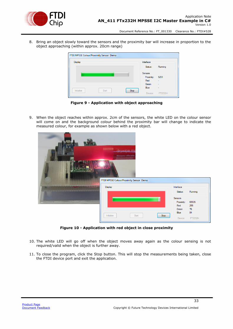
Application Note
AN_411 FTx232H MPSSE I2C Master Example in C# Version 1.0
Document Reference No.: FT_001330 Clearance No.: FTDI#528
33 Product Page
Document Feedback Copyright © Future Technology Devices International Limited
8. Bring an object slowly toward the sensors and the proximity bar will increase in proportion to the
object approaching (within approx. 20cm range)
Figure 9 - Application with object approaching
9. When the object reaches within approx. 2cm of the sensors, the white LED on the colour sensor
will come on and the background colour behind the proximity bar will change to indicate the measured colour, for example as shown below with a red object.
Figure 10 - Application with red object in close proximity
10. The white LED will go off when the object moves away again as the colour sensing is not required/valid when the object is further away.
11. To close the program, click the Stop button. This will stop the measurements being taken, close
the FTDI device port and exit the application.

Application Note
AN_411 FTx232H MPSSE I2C Master Example in C# Version 1.0
Document Reference No.: FT_001330 Clearance No.: FTDI#528
34 Product Page
Document Feedback Copyright © Future Technology Devices International Limited
10 Conclusion
This application note and accompanying example have demonstrated the implementation of a USB-I2C Master interface with the FTx232H devices, along with the use of the FTDI C# wrapper to control the device from a graphical user interface. In addition, it has explained the features of the MPSSE which are
used when implementing the I2C protocol.
The code is intended to be modified to suit a wide range of I2C interfacing and sensing applications and can be used with other I2C sensors and peripherals.
FTDI have a range of FTx232H-based modules including UM232H, UM232H-B, FT2232H mini modules, FT4232H mini modules and the C232HM cables. This application will work well with all of these modules as well as with the IC itself if placed on a custom designed PCB.
FTDI have a range of other bridging devices capable of I2C Master implementation including the FT4222H and the FT260. The FT260 is the latest addition to the range of USB to I2C Master bridge devices and is a
HID class device which means that it can be used without loading a separate D2xx driver. Further information can be found on these products at the FTDI homepage www.ftdichip.com
Application Note
AN_411 FTx232H MPSSE I2C Master Example in C# Version 1.0
Document Reference No.: FT_001330 Clearance No.: FTDI#528
35 Product Page
Document Feedback Copyright © Future Technology Devices International Limited
11 Contact Information
Head Office – Glasgow, UK Branch Office – Tigard, Oregon, USA
Future Technology Devices International Limited
Unit 1, 2 Seaward Place, Centurion Business Park Glasgow G41 1HH United Kingdom Tel: +44 (0) 141 429 2777 Fax: +44 (0) 141 429 2758
Future Technology Devices International Limited (USA)
7130 SW Fir Loop Tigard, OR 97223-8160 USA Tel: +1 (503) 547 0988 Fax: +1 (503) 547 0987
E-mail (Sales) [email protected] E-mail (Sales) [email protected] E-mail (Support) [email protected] E-mail (Support) [email protected] E-mail (General Enquiries) [email protected] E-mail (General Enquiries) [email protected]
Branch Office – Taipei, Taiwan Branch Office – Shanghai, China
Future Technology Devices International Limited (Taiwan) 2F, No. 516, Sec. 1, NeiHu Road Taipei 114 Taiwan , R.O.C. Tel: +886 (0) 2 8797 1330 Fax: +886 (0) 2 8751 9737
Future Technology Devices International Limited (China) Room 1103, No. 666 West Huaihai Road, Shanghai, 200052 China Tel: +86 21 62351596 Fax: +86 21 62351595
E-mail (Sales) [email protected] E-mail (Sales) [email protected] E-mail (Support) [email protected] E-mail (Support) [email protected] E-mail (General Enquiries) [email protected] E-mail (General Enquiries) [email protected]
Web Site
http://ftdichip.com
Distributor and Sales Representatives
Please visit the Sales Network page of the FTDI Web site for the contact details of our distributor(s) and sales representative(s) in your country.
System and equipment manufacturers and designers are responsible to ensure that their systems, and any Future Technology Devices
International Ltd (FTDI) devices incorporated in their systems, meet all applicable safety, regulatory and system-level performance requirements. All application-related information in this document (including application descriptions, suggested FTDI devices and other
materials) is provided for reference only. While FTDI has taken care to assure it is accurate, this information is subject to customer
confirmation, and FTDI disclaims all liability for system designs and for any applications assistance provided by FTDI. Use of FTDI
devices in life support and/or safety applications is entirely at the user’s risk, and the user agrees to defend, indemnify and hold
harmless FTDI from any and all damages, claims, suits or expense resulting from such use. This document is subject to change without
notice. No freedom to use patents or other intellectual property rights is implied by the publication of this document. Neither the whole
nor any part of the information contained in, or the product described in this document, may be adapted or reproduced in any material
or electronic form without the prior written consent of the copyright holder. Future Technology Devices International Ltd, Unit 1, 2
Seaward Place, Centurion Business Park, Glasgow G41 1HH, United Kingdom. Scotland Registered Company Number: SC136640
Application Note
AN_411 FTx232H MPSSE I2C Master Example in C# Version 1.0
Document Reference No.: FT_001330 Clearance No.: FTDI#528
36 Product Page
Document Feedback Copyright © Future Technology Devices International Limited
Appendix A - References
Document References
Product Pages
FT232H
FT2232H
FT4232H
IC Datasheets
FT232H Datasheet
FT2232H Datasheet
FT4232H Datasheet
Hardware
UM232H and UM232H Datasheet
USB Hi-Speed Cables and C232HM Cables Datasheet
UM232H-B and UM232H-B Datasheet
FT2232H Mini-Module and FT2232H Mini-Module Datasheet
FT2232H-56 Mini-Module and FT2232H-56Q Mini-Module Datasheet
FT4232H Mini-Module and FT4232H Mini-Module Datasheet
FT4232H-56 Mini-Module and FT4232H-56Q Mini-Module Datasheet
MPSSE Documents
AN_108 Command Processor for MPSSE and MCU Host Bus Emulation Modes
AN_135 MPSSE Basics
Application Notes
AN_355 FT232H MPSSE Example-I2C Master Interface with Visual Basic
AN_255 USB to I2C Example Using the FT232H and FT201x Devices (C++)
AN_113 Interfacing FT2232H Hi-Speed Devices to I2C Bus
Additional References
D2XX Drivers
C# .NET Wrapper
AN_411 Source Code

Application Note
AN_411 FTx232H MPSSE I2C Master Example in C# Version 1.0
Document Reference No.: FT_001330 Clearance No.: FTDI#528
37 Product Page
Document Feedback Copyright © Future Technology Devices International Limited
Acronyms and Abbreviations
Terms Description
GPIO General Purpose Input Output
I2C Inter-IC bus
LED Light Emitting Diode
MPSSE Multi-Protocol Synchronous Serial Engine
USB Universal Serial Bus
VB Net Visual Basic .NET
Application Note
AN_411 FTx232H MPSSE I2C Master Example in C# Version 1.0
Document Reference No.: FT_001330 Clearance No.: FTDI#528
38 Product Page
Document Feedback Copyright © Future Technology Devices International Limited
Appendix B – List of Tables & Figures
List of Tables
Table 1 - Features by device type ................................................................................................... 5
List of Figures
Figure 1 - Sensor hardware and application ..................................................................................... 4
Figure 2 - Schematics.................................................................................................................... 6
Figure 3 - Prototype Hardware........................................................................................................ 9
Figure 4 - Application window ....................................................................................................... 11
Figure 5 - I2C transfers for Proximity sensor ................................................................................... 13
Figure 6 - I2C Transfers for Colour sensor ...................................................................................... 16
Figure 7 - Three-Phase clocking .................................................................................................... 20
Figure 8 - Application window after opening the program ................................................................. 32
Figure 9 - Application with object approaching ................................................................................ 33
Figure 10 - Application with red object in close proximity ................................................................. 33
Application Note
AN_411 FTx232H MPSSE I2C Master Example in C# Version 1.0
Document Reference No.: FT_001330 Clearance No.: FTDI#528
39 Product Page
Document Feedback Copyright © Future Technology Devices International Limited
Appendix C – Revision History
Document Title : AN_411 FTx232H MPSSE I2C Master Example in C#
Document Reference No. : FT_001330
Clearance No. : FTDI#528
Product Page : http://www.ftdichip.com/FTProducts.htm
Document Feedback : Send Feedback
Revision Changes Date
1.0 Initial Release 2017-05-17