fuel cell r&d and demonstration - us department of … conditions can rapidly degrade cell...
TRANSCRIPT

FUEL CELL R&D AND DEMONSTRATION
Robert E. Fields, E. John Rowley, Mahlon S. Wilson and Christine Zawodzinski,
Materials Science and Technology Division, MS D429 Los Alamos National Laboratory, Los Alamos, NM 87545
Introduction
Hydrogen fuel cells have yet to have any meaningful commercial success. Obstacles include cost, reliability, fuel supply / storage and overcoming entrenched competition. The first market entry points will probably be those areas where the extra cost and fuel inconvenience are offset by the advantages of the fuel cell over the previous technology. A power range where this may apply is on the several-hundred watt level, where batteries are unwieldy and internal combustion engines are inefficient and noisy. A potentially interesting commercial application for several-hundred watt fuel cells is in powering personal mobility vehicles (PMVs). These include powered wheelchairs and three-wheeled electric powered “scooters” often used by the elderly or infirm. The users of PMVs are often located in environments where hydrogen supply could be established (e.g., nursing homes or hospitals) or are otherwise often routine customers of medical supply houses. The usefulness and benefits of PMVs to many users are often limited by battery considerations. The additional range (and possibly life and reliability) offered by fuel cells may more than compensate for higher cost and fuel supply issues.
Figure 1. A Victory® Personal Mobility Vehicle (scooter).
1
Proceedings of the 2002 U.S. DOE Hydrogen Program Review NREL/CP-610-32405

To this end, we have modified a Victory® personal mobility vehicle (Pride Mobility Products Corp., Exeter, PA), as shown in Figure 1, to accept a mid-range fuel cell system with a custom monitoring, control, and data logging electronics package (Figure 2). The control system consists of two components – a main monitor and control board which handles low-level monitoring and near real-time protection features, and a Handspring (Mountain View, CA) Visor Pro personal digital assistant (PDA) that acts as an operator display, data logger, and provides manual systems control. The electronics protect the fuel cell stack and store operational information that can be used to further optimize stack installation and operation.
Figure 2. Monitoring and control circuit board mounted on the scooter drive unit.
Electrical System
The vehicle has a hybrid power system comprised of a LANL-constructed, 40 cell, 35 cm2, annular, active/passive PEM fuel cell stack and a 24-volt, 3.4 ampere-hour sealed lead acid battery pack (4 x LC-R063R4P, Matsushita Electric Corporation of America, Secaucus, NJ) to supply current for peak loads. A DC-DC converter (V24AV24C400A, Vicor Corp., Andover, MA) regulates the output voltage of the stack to 26.0 volts while the electronics package monitors stack condition and system load. The electrical system is shown in block diagram form in Figure 3. The custom circuitry attaches to the stock scooter wiring harness and the new fuel cell power circuits in numerous locations to allow monitoring and control. Subcircuits on the main board serve multiplexing, gain, and filtering functions and allow switching of external loads.
2
Proceedings of the 2002 U.S. DOE Hydrogen Program Review NREL/CP-610-32405

HydrideTank
DC-DCConverter
Batteries
SpeedController
TractionMotor
Fuel CellStack
MAIN BOARDCell Voltages
Regenerative Power IN
RS-232Comms
Current / Voltage
Pressures
Temperatures
Power OUT
Speed
AmbientT
T
T
T
T
P
PP
P
Ambient
Figure 3. Electrical system block diagram. Monitoring of stack cell voltages is fundamental to proper stack operation under real-world loading conditions. All 40 individual cell voltages are monitored to determine stack health while stack voltage and current are used to monitor stack performance. In addition, current and voltage are monitored in several other key locations in the scooter power bus: the output of the DC-DC converter, the connections to the lead acid batteries, and to the traction motor. These signals allow monitoring of systems performance, location of lossy subsystems, and will allow further optimization. Current monitoring is accomplished using simple 2 mΩ 4-terminal Kelvin shunts (Isotek PBV series, Boston, MA). Other systems-critical and environmental conditions are also monitored. The Ergenics (Ringwood, NJ) hydride storage tank pressure, hydrogen pressure in the stack, as well as ambient atmospheric pressure are monitored using Omega (Stamford, CT) PX-105 and PX-138 pressure transducers. Ambient temperature, temperature in the fuel cell stack exhaust air, and near the neck and base of the hydride storage tank are monitored using National Semiconductor (Santa Clara, CA) LM-92 precision temperature transducers. Provision is also included to monitor humidity of the stack exhaust air, incline of the vehicle, and vehicle speed though these functions have not been implemented at this writing. Proper operation of the fuel cell stack installation for startup and normal operation requires control of a number of accessory circuits. The circuitry includes provisions to control a solenoid-operated stack purge valve (EE3-TL-24-H, Clippard Minimatic®, Cincinnati, OH), a 30A stack shorting relay (G8P-1A4TP-DC24, Omron®, Tokyo, Japan), a Whiffet® blower (Comair Rotron, San Diego, CA) to actively draw air through the fuel cell stack, and on/off control of the DC-DC converter. As part of the load-shedding strategy in cases where system demand exceeds the power supply capability of both the stack and the battery pack, the circuit also includes the capability to override the operator throttle setting and reduce speed to a sustainable level. A Visor PDA is used as both operator display and for data logger storage through the use of a Portable Innovation Technology (Hong Kong, China) MemPlug™ CompactFlash™ adapter card and programming to log the performance data to a SanDisk (Sunnyvale, CA) 64 MB memory
3
Proceedings of the 2002 U.S. DOE Hydrogen Program Review NREL/CP-610-32405
card. The Visor communicates with the microcontroller on the main systems board through a logic-level RS-232 serial interface operating at 19.2 kbaud. The Visor drives communications using single character commands with single and multi-byte responses from the systems board. Power Section One of the main functions of the electronics package is to protect the fuel cell stack from reverse electrolytic processes in individual fuel cells under conditions of extreme load, cell flooding, etc. Such conditions can rapidly degrade cell performance to the point of increased internal resistance, permanent loss of cell function, reduced power capability, and ultimately, a complete loss of the stack. The scooter is equipped with a Model 1228 electronic speed control module from Curtis Instruments, Inc. (Mount Kisco, NY) which has provisions for speed (i.e. load) limiting through auxiliary circuitry. If one or more cell voltages are reduced to a critical level by any process, the custom monitoring and control circuit intercedes and reduces overall system load by reducing the scooter maximum speed. If the stack continues to experience distress, the circuit turns off the DC-DC converter until stack voltages recover and allows the scooter to continue to operate at reduced range using the boost batteries. Load sharing between the fuel cell stack and the batteries is accomplished passively by simply inserting a 1 Ω wire-wound resistor in series with the DC-DC converter output. The 1 Ω resistor approximately compensates for the internal resistance of the battery pack during heavy loading. During periods of peak loading, the system bus voltage drops and both the DC-DC converter and the batteries share the current load. While somewhat wasteful of power, this method of load balancing is extremely simple. At peak current delivery by the DC-DC converter (7 amps for this stack), this loss is approximately 50 watts. This loss appears significant but in routine operation of the scooter is of very short duration (<3-5 seconds) though at cruise there will still be a loss (approximately 4-6 watts). Circuitry is being implemented to throttle the output of the DC-DC converter in real time to control stack loading more accurately and efficiently. As stack efficiency is directly related to stack loading, status and predictive techniques could be used to operate the stack at highest efficiency as much of the time as possible, thereby increasing overall scooter range. Microcontroller The main circuit consists of analog, digital, and communications subsytems with an Atmel (San Jose, CA) ATmega163 AVR reduced instruction set (RISC) microcontroller performing all systems monitoring, control, analog-to-digital conversions (ADC), and communications with serial peripherals and the Visor touchscreen dashboard. The microcontroller operates at a 4 MHz clock speed and has on board circuitry to perform 10-bit ADC functions, serial communication, bitwise input/output (I/O), watchdog functionality, etc. Programming was accomplished in C using an open source GNU compiler (AVR-GCC, Copyright 2001, Free Software Foundation) and Atmel AVR Studio software. An Atmel STK-500 development circuit board was used to test code and allow in-system programming of the microcontroller. The software was configured in an endless loop, cycling at 25 Hz, that monitors system parameters, listens for commands from the Visor, and performs whatever actions are necessary to protect the fuel cell stack based on the various system input values. Stack cell voltages are always scanned each time through the loop. If any fuel cell stack cells drop in potential to the first load-shedding threshold (0.3 volts), an AD5242 electronic 100kΩ I2C interface potentiometer (Analog Devices, Norwood, MA) inserted into the scooter speed control circuit is adjusted downward to reduce scooter speed. Below 0.2 volts on any cell, the DC-DC converter is switched off to completely isolate the stack from loading and allow the stack to
4
Proceedings of the 2002 U.S. DOE Hydrogen Program Review NREL/CP-610-32405

recover. Once the lowest cell in the stack has recovered to 0.6 volts, the DC-DC converter is switched back on to allow normal operation and monitoring continues. The fuel cell stack operates in both active and passive air circulation modes determined by stack loading. Each time through the main loop, if cell voltage has dropped below 0.6 volts, the air circulation fan is energized to pull more air into the stack air channels. At idle, the stack fan will occasionally pulse on momentarily to keep batteries topped off or supply power for other drains on the system, though when the stack is under load, the fan runs continuously. The microcontroller also checks at the start of each loop iteration to determine if there have been any commands from the Visor dashboard and if so, responds with whatever information or action was requested. Analog Section The 40 fuel cell voltages are sampled at tabs on stainless steel cell separator plates. Voltages are brought to the main circuit board through a 41-wire ribbon cable and passed through ferrite beads to reduce high frequency noise. The voltages are then ground referenced by Analog Devices AD629 high common-mode voltage difference amplifiers, individually selected by 16-to-1 Analog Devices ADG506A multiplexers, buffered and filtered with 10 kHz corner frequency, two-pole, Sallen-Key low-pass active filters, and routed to three of the eight analog inputs of the Atmel microcontroller. Use of three 16-to-1 multiplexers allows this circuit to work with stacks of up to 48 cells. The various other analog signal sources are configured similarly. Communication Communication between the Visor PDA and the main electronics board is implemented using 19,200 baud, logic-level serial communication. Communication is initiated by the Visor sending a single character command to the main board. At the beginning of each iteration of the program loop, the Atmel microcontroller checks to see if a command has been received and if so, acts on the command directly or sets a flag so that monitoring routines will report values back to the PDA. Direct commands are acknowledged if successful by echoing the command character back to the Visor. Requests for data are acknowledged by simply returning the data.
Figure 4. Scooter operator display screens. A is the main control screen, B is the stack cell voltage display showing a loaded stack, and C is the volts and amps display.
5
Proceedings of the 2002 U.S. DOE Hydrogen Program Review NREL/CP-610-32405

Operator Display The Visor PDA is used for basic control of the fuel cell system, detailed data display, and for data logging of system performance. The operator interface consists of five display screens that the operator can navigate using touch-sensitive onscreen buttons or through a conventional menu system (Figure 4). A main screen allows control of stack purge, shorting, and on/off control of the DC-DC converter. A “volts and amps” screen shows current and voltage out of the stack, out of the DC-DC converter, in and out of the battery pack, and in and out of the traction motor. A temperatures screen shows the temperatures at four separate sampling points on the scooter system – the stack, the hydride tank neck and base, and ambient temperature under the scooter mechanical shroud. The pressures screen shows the hydrogen pressure monitored at the entrance and exit of the pressure regulator (the hydride tank and stack pressures, respectively), and ambient atmospheric pressure. A final screen displays the forty individual fuel cell voltages as bar graphs with other stack data. On this screen, the operator can tap on a particular cell’s bar and the Visor will then highlight that bar and display the voltage for that cell. All displays are updated at a 4 Hz rate to provide near real time information. Operation The circuitry is automatically energized when the scooter power key is inserted. The main circuit initializes all functionality to a safe, powered off condition. The Visor software starts at the main control page where the operator can purge the stack, momentarily short the stack if necessary, and finally engage the DC-DC converter. From that point on, the circuit monitors the stack and peripheral circuits, protects the stack through the load-shedding circuitry, controls the stack fan based on power demand, and responds to data requests or commands from the Visor. Once the fuel cell is operating, the scooter may be used entirely as a conventional scooter.
Hydrogen System and Cart Layout A central design premise of the fuel cell system employed in the fuel cell scooter was to fit all fuel cell system componentry in the space under the original shroud without any modification of the shroud. If any equipment such as a hydrogen cylinder were to be mounted outside of the OEM shroud, it would create an overly modified appearance, which was considered undesirable for this project. As is seen in figures 5 and 6, this design objective was achieved.
Figure 5. Fuel cell powered electric cart.
6
Proceedings of the 2002 U.S. DOE Hydrogen Program Review NREL/CP-610-32405

Figure 6. Layout of fuel cell system. Since the original two 12V lead-acid batteries resided under the shroud, removal of these batteries offered a fair amount of space for mounting of a suitable hydrogen supply. Various hydrogen supply systems were considered such as compressed hydrogen, chemical hydrides, and hydrogen storage alloy filled cylinders (metal hydride). In the end, an AB5 Mischmetal (LaMmNi4.15Fe0.85) hydrogen storage alloy filled cylinder was specified (Ergenics ST-25-AL hydrogen storage unit, Ringwood, NJ) as this was deemed the safest, most commercially developed hydrogen source with the highest volumetric hydrogen capacity currently available.
Hydrogen storage alloy (metal hydride) systems offer many advantages over other hydrogen delivery systems. First and foremost, a metal hydride system is far safer than a compressed gas cylinder of equivalent volume. Should a metal hydride system suffer a failure such as a rupture, it would outgas hydrogen slowly whereas a compressed tank could fail catastrophically, potentially causing serious injury to the scooter operator by either shrapnel and/or explosion modalities. Metal hydride systems have a distinct advantage in terms of volumetric hydrogen capacity over compressed hydrogen systems, although the gravimetric density may actually be less (depending on size and containment materials, etc.).
The major disadvantages of metal hydride systems are their cost and gravimetric hydrogen capacity. The metal hydride tank specified had a weight of 37 pounds while holding approximately 1000 liters of hydrogen. Thirty-seven pounds is much heavier than a tank of compressed hydrogen in most cases. Since the batteries removed from the scooter weighed just over 50 pounds, this was not such an issue for the scooter as it may be with more weight sensitive applications. Since safety and having a large enough volume of hydrogen to be considered useful (e.g. range of operation) were the main design concerns, the metal hydride cylinder was clearly the best choice.
7
Proceedings of the 2002 U.S. DOE Hydrogen Program Review NREL/CP-610-32405
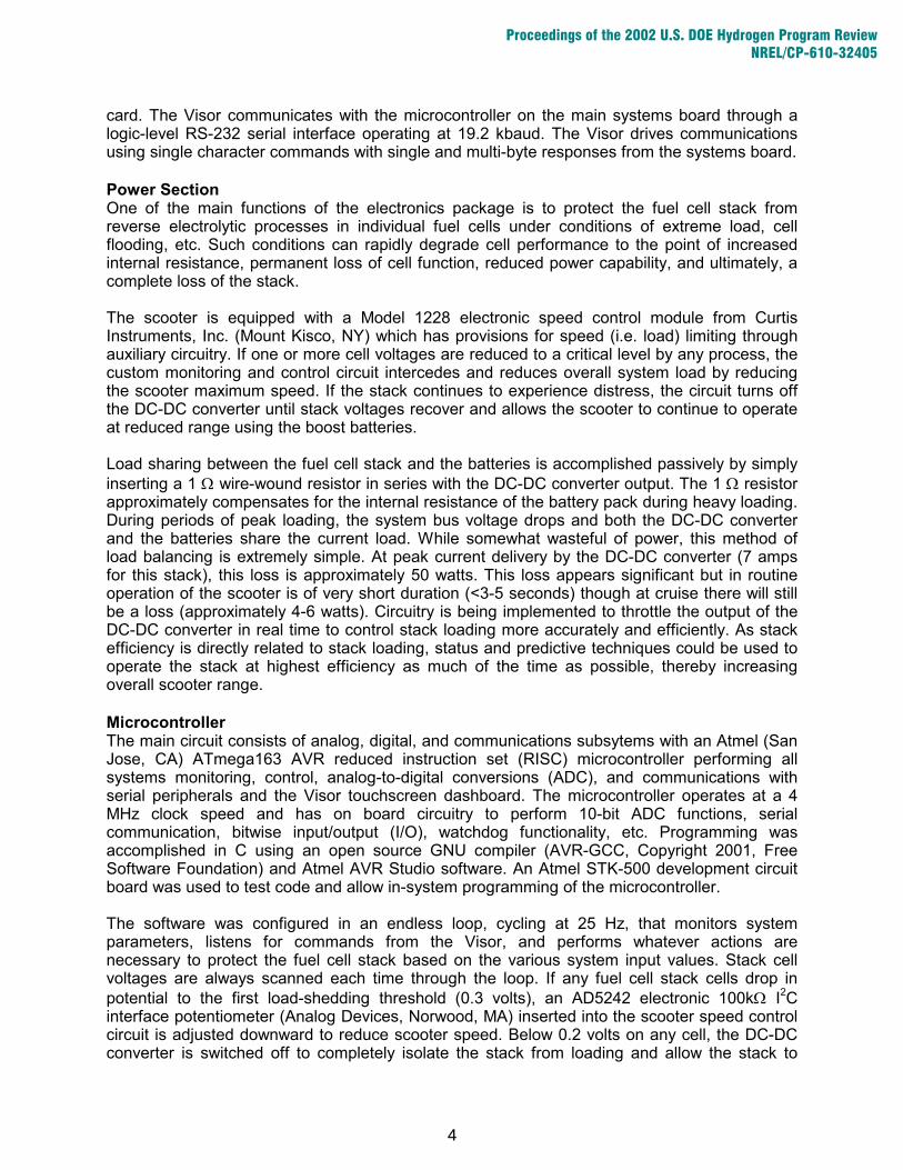
In Figure 7, the metal hydride cylinder is mounted on specially designed machined cradles in a transverse manner relative to the axial direction of the scooter. These cradles are also shown below in Figure 8. The cradles were lined with GreptileTM gripping tape (3M Company, St. Paul, MN) to prevent unwanted movement of the tank. Quick releasing yet positive locking Burton snowboard straps (Burlington, VT) were utilized to hold the metal hydride tank to the machined cradles. This unconventional arrangement holds the metal hydride tank securely to the scooter, yet allows the tank to be quickly removed for refilling or other maintenance purposes. A quick coupling (Colder Products Corporation, St. Paul, MN) allows the tank to be removed without the stainless steel braided Teflon® gas line (Swagelok Company, Solon, OH) to further enhance the safety and portability of the metal hydride tank.
Figure 7. H2 subsystem layout. Since the flow rate of the metal hydride cylinder slows down as the tank discharges hydrogen and subsequently cools, additional heat enveloping the tank is necessary to maintain the higher flow rates necessary for proper fuel cell operation. The active air breather fuel cell stack itself puts out more than enough heat so a 24VDC Whiffet® side discharge blower was mounted above the stack and plastic ducting was constructed to direct the heated exhaust air onto the metal hydride cylinder. A secondary measure for heating the tank was designed both as a mount for the DC-DC converter and a heat transfer mechanism. The underside of this cradle with the DC-DC converter and control boards mounted is shown in Figure 8. The DC-DC converter specified operates with an efficiency rating of approximately 90%. Since the additional 10% is lost as waste heat, a spring-loaded DC-DC converter mounting cradle/heat sink device was designed to transfer waste heat from the converter to the metal hydride tank. Figure 3 shows this machined cradle in its mounted mode underneath the metal hydride tank (bottom left of picture). Figure 9 shows the machined cradle with the metal hydride tank removed for better clarity.
8
Proceedings of the 2002 U.S. DOE Hydrogen Program Review NREL/CP-610-32405

Figure 8. DC-DC converter mount / heat transfer cradle - Bottom view.
Figure 9. Machined DC-DC Converter mount / heat transfer cradle - Top view. Even when the metal hydride tank has been operating for quite some time and has therefore cooled, the metal hydride tank discharges hydrogen at a rate that would be damaging (e.g. overly high) to the fuel cell stack. In order to regulate the flow of hydrogen to the fuel cell stack, a pressure-reducing regulator is necessary. The regulator chosen was a piston-sensed pressure-reducing regulator manufactured by the Tescom Corporation of Elk River Minnesota. In tests performed by Tescom, the Tescom unit varied only 0.8 psi in outlet pressure when an inlet pressure drop from 300 to 10 psi was employed. This steady flow characteristic, as well as a very safe maximum working inlet pressure rated at 6000 psi, led to the specification of this regulator. The specified Tescom regulator is shown in Figure 10.
9
Proceedings of the 2002 U.S. DOE Hydrogen Program Review NREL/CP-610-32405

Figure 10. Piston-sensed pressure-reducing regulator.
Fuel Cell Stack
For several years on through FY’01, the Hydrogen Program funded a program on polymer electrolyte fuel cells for small battery replacements. As described in recent Hydrogen Program technical papers, a novel fuel cell stack was developed at LANL that was referred to as the “air-breather” because its unique open periphery configuration allowed a very simple and reliable passive fuel cell device. LANL worked with Enable Fuel Cell Corporation (a subsidiary of DCH Technologies) in a Cooperative Research and Development Agreement (CRADA) to create commercial products. By necessity, the battery replacements needed to be very simple and passive (with no moving parts) to be competitive with batteries on the under 10W power level. On the other hand, it was also observed that introducing a simple cooling fan could significantly increase performance by approximately a factor of two, because ultimately the hydration level of the fuel cell depends on temperature. While this may or may not be useful on the small power scales, it provoked interest in developing a system that could operate on the level of several hundred watts. The general construction of the larger system is basically the same as the original 2” (5.1 cm) diameter “airbreather” in order to keep a very simple, radially symmetrical and hence low-cost stack. Special provisions are added to accommodate a forced-flow air stream. In addition, the active area is increased by roughly a factor of three by increasing the stack diameter to 3” (7.6 cm). In a purely passive mode, currents would not be any higher than the smaller stack because of the diffusion access limitations, but with forced airflow in an “active” mode, significantly higher currents are generated. Indeed, the current densities with continuous operation in active mode are about twice that of the standard passive air-breather. Coupled with the tripling of active area, total currents about six times greater are achieved. One of the major concerns with retaining the simple annular feed hydrogen manifold configuration in the significantly larger cell was difficulty with the hydrogen delivery to the far reaches of the periphery. As it turned out, hydrogen supply did not limit cell performance. In some single-cell configurations, currents up to 15 A could be sustained (however, such configurations would quickly overheat and dry out a stack, and hence are impractical for the scooter system). In order to prevent dryout, the cathode flow-fields were modified to limit the diffusion access of air to the cathode. While performance of a cold cell is decreased, the loss of water is also
10
Proceedings of the 2002 U.S. DOE Hydrogen Program Review NREL/CP-610-32405

reduced which allows the cells to operate at higher temperatures in the active mode without dryout. After single-cell testing to check issues such as sealing, assembly and hydrogen access, four-cell short stacks were assembled and tested in a manner that would ideally replicate the conditions experienced by the cells in the midst of a 40-cell stack. The endplates were consequently heated with strip heaters to simulate the heat generated by adjacent cells. Cathode flow-field impregnation levels were then chosen that would provide the best compromise between performance and avoiding dry-out. A particular impregnation level was selected and a 40-cell stack assembled using similar fills. Figure 11 shows the differences in performance between the “optimal” 4-cell stack and the scale-up to 40-cells.
0.0
0.2
0.4
0.6
0.8
1.0
0.00 0.05 0.10 0.15 0.20 0.25 0.30
Actv6,8 VIRs
4-Cell Stack Average Voltage Ave. Resistance 40-Cell Stack Average Voltage Ave. ResistanceA
ve. C
ell H
F R
esis
tanc
e (o
hm c
m2 ) o
rA
vera
ge C
ell V
olta
ge (V
)
Current Density (A/cm 2)
After Continuous 0.6 V/cell Operation0.76 atm Ambient Pressure
0.20" Manifold Pressures12 psig Hydrogen
Figure 11. Scale-up of the fuel cell stack from 4 to 40 cells.
As shown in Figure 11, the 40-cell stack under performs the 4-cell and runs somewhat drier at the higher currents (as determined by the higher cell resistances). Although some losses in performance are usually expected with scale-up, an additional possibility for the differences is that the cathode impregnations were done one-by-one by hand in the 4-cell case and in a single batch process in the 40-cell case. Although loadings were similar, the distribution of the impregnant may have been substantially different with the two processes. Despite the less than optimal scale-up, the 40-cell stack behaved well on the test stand. It was robust and relatively insensitive to varying conditions and was not plagued by unduly problematic cells. It also transitioned well between active and passive modes. Active / Passive Operational Modes At idle, the scooter draws power to operate the system electronics and any auxiliaries such as the light or horn. The fuel cell version has additional loads from the PDA and fuel cell system specific electronics. In general, it is desirable for the fuel cell to provide the idle power so that the batteries can be maintained at an optimal state of charge. Efficiency is also an issue if the idle is a significant part of the duty cycle, as using the batteries introduces charge/discharge inefficiencies to the process. However, if significant parasitic draw is necessary to operate the fuel cell under idle conditions, the system efficiency at idle may plummet. Consequently, it is desirable to operate the stack in the passive mode at idle if possible to avoid the significant parasitic power draw of the fan. A secondary benefit of passive operation is that the stack becomes well hydrated when generating current without the fan on to remove the water. Then,
11
Proceedings of the 2002 U.S. DOE Hydrogen Program Review NREL/CP-610-32405

when the scooter motor is activated, the stack is well hydrated and comes up to high power quickly. Otherwise a lag would be incurred as the stack slowly rehydrates itself.
0
50
100
150
200
0.0 0.5 1.0 1.5 2.0
Actv8 LT2b Fig
Pow
er (W
atts
)
Time (hours)
"Idle" - 30 V Stack, No Blower
"Cruise" - 24V Stack, 24 V Blower
Figure 12. Operation of the 40-cell stack on active and passive modes.
Figure 12 shows continuous operation of the 40-cell stack on the test stand alternating between active (fan on) operation at 24V and passive at 30 V. In active “cruise,” the stack provides about 140 W, slightly more than the power requirement of the scooter at full speed on a level surface. At the passive “idle,” it provides over 30 W, more than enough for all of the electronics and auxiliaries. As can be seen, performance is temporarily improved upon switching from one mode to the other. This is not observed when switching from low to high power with the fan always on. Consequently, for both performance and efficiency the dual nature of active / passive operation provided by the stack design provides advantages. Although only limited testing of the fuel stack and stack system installed on the scooter has been accomplished, the stack appears to be more than equal to the task and has functioned appropriately in the transitions between active and passive modes. Since battery charging is a significant power draw above and beyond the other idle parasitics, efficient strategies need to be developed for the transition between active and passive to charge at an optimal rate.
Future Work As the scooter has only recently become operational, the first goal is to completely calibrate all sensors and benchmark its performance and range to compare it to a conventionally-equipped scooter of the same model. Through this work, lifetime information for the fuel cell equipped scooter will also be obtained through data logging of all systems performance figures and allow a complete cost/benefit comparison to be drawn. Though the scooter is functional in its current form, significant advances in stack operation automation and fuel efficiency could be achieved though additional work on real-time regulation of the DC-DC converter output voltage and with additional sophistication of the microcontroller firmware. By regulating the output of the DC-DC converter directly, the series resistor required for proper load sharing would be eliminated along with the 50 watts wasted during peak
12
Proceedings of the 2002 U.S. DOE Hydrogen Program Review NREL/CP-610-32405

loadings. This would decrease the drain on the batteries and allow longer load peaks, such as climbing a long incline, to be accomplished without resorting to load shedding strategies. Additionally, the microcontroller firmware could be advanced to the point where no operator intervention is required to bootstrap or operate the scooter. As startup and stack conditioning functionality was incorporated into the firmware, operation would become identical to a battery-powered scooter – the ultimate goal of this project. On the hydrogen storage issue, future work could possibly entail the use of safe hydrogen storage technologies that provide higher fuel yields, should they and willing suppliers be identified. Additionally, another demonstration platform of interest is a powered wheelchair. Wheelchair users tend to be highly dependent upon their PMV, so range improvements with fuel cells are of great interest. These typically use two separate motor drives and controllers with each set powering a drive wheel, consequently power demand is significantly greater than with a scooter. To a large extent, the power density of the active / passive stack is limited by its configuration. A second generation design may possibly double the power density, which is intrinsically of interest and a probable necessity for the powered wheelchairs.
Conclusion
Within the first year of this project, the control and monitoring electronics, hydrogen fuel supply system, and fuel cell stack have been developed and installed into an operational personal mobility vehicle. At this early stage, much is yet to be characterized and optimized and the system further simplified to attain the goal of a potentially commercially competitive system for hydrogen fuel cells in the several-hundred watt range.
13
Proceedings of the 2002 U.S. DOE Hydrogen Program Review NREL/CP-610-32405