fuel injector design optimization using gt-suite · 2016-07-01 · rbei/eei4 | 10/14/2015 | ©...
TRANSCRIPT

RBEI/EEI4 | 10/14/2015 | © Robert Bosch Engineering and Business Solutions Private Limited 2015. All rights reserved, also regarding any disposal, exploitation, reproduction, editing, distribution, as well as in the event of applications for industrial property rights.
GT Conference- Fuel Injector Design Optimization
1
Fuel Injector Design Optimization using GT-SUITE
GT Conference 201507/12/2015
Aurobbindo L

RBEI/EEI4 | 10/14/2015 | © Robert Bosch Engineering and Business Solutions Private Limited 2015. All rights reserved, also regarding any disposal, exploitation, reproduction, editing, distribution, as well as in the event of applications for industrial property rights.
GT Conference- Fuel Injector Design Optimization
Agenda
1 Motivation/Objective
2 Modeling approach
3 Simulation and Validation
4 DOE setup and Simulation
5 Summary

RBEI/EEI4 | 10/14/2015 | © Robert Bosch Engineering and Business Solutions Private Limited 2015. All rights reserved, also regarding any disposal, exploitation, reproduction, editing, distribution, as well as in the event of applications for industrial property rights.3
GT Conference- Fuel Injector Design Optimization
1 Motivation/Objective
2 Modeling approach
3 Simulation and Validation
4 DOE setup and Simulation
5 Summary

RBEI/EEI4 | 10/14/2015 | © Robert Bosch Engineering and Business Solutions Private Limited 2015. All rights reserved, also regarding any disposal, exploitation, reproduction, editing, distribution, as well as in the event of applications for industrial property rights.
GT Conference- Fuel Injector Design Optimization
4
Motivation for simulationUse of simulation in early development phase
Enable evaluation of new concept before the hardware exists
Identify the optimal design parameters with given constraints before the
hardware development
Reduce number of prototypes developed
Reduce actual hardware testing time
Objective: To determine the optimal Fuel Injector design parameters to
achieve the target fuel flow rate

RBEI/EEI4 | 10/14/2015 | © Robert Bosch Engineering and Business Solutions Private Limited 2015. All rights reserved, also regarding any disposal, exploitation, reproduction, editing, distribution, as well as in the event of applications for industrial property rights.
GT Conference- Fuel Injector Design Optimization
1 Motivation/Objective
2 Modeling approach
3 Simulation and Validation
4 DOE setup and Simulation
5 Summary
5

RBEI/EEI4 | 10/14/2015 | © Robert Bosch Engineering and Business Solutions Private Limited 2015. All rights reserved, also regarding any disposal, exploitation, reproduction, editing, distribution, as well as in the event of applications for industrial property rights.
Modeling approachGT Conference- Fuel Injector Design Optimization
Main requirements of Injector: Target Fuel Flow rate Spray atomization Penetration depth Spray shape Spray size -SMD
Based on Fishbone analysis , the influencing parameters have been identified which would determine the flow rate
3D Injector model
6
Fuel supply pressure

RBEI/EEI4 | 10/14/2015 | © Robert Bosch Engineering and Business Solutions Private Limited 2015. All rights reserved, also regarding any disposal, exploitation, reproduction, editing, distribution, as well as in the event of applications for industrial property rights.7
GT Conference- Fuel Injector Design Optimization
Modeling approach Contd., Understand Injector construction from 3D & AutoCAD drawings & Build
Injector Model using Hydraulics & Pneumatics Library in GT-SUITE
Parameterization of model to achieve desired Injection profile
Achieve pressurized injector flow rate as per injector specifications in the
simulation
Changes in the boundary conditions like supply pressure and observe if
the model could capture the flow dynamics
Match low pressure injection test bench data results with simulation
results
Conduct DoE to achieve the target Fuel flow rate with low pressure

RBEI/EEI4 | 10/14/2015 | © Robert Bosch Engineering and Business Solutions Private Limited 2015. All rights reserved, also regarding any disposal, exploitation, reproduction, editing, distribution, as well as in the event of applications for industrial property rights.8
GT Conference- Fuel Injector Design Optimization
1 Motivation/Objective
2 Modeling approach
3 Simulation and Validation
4 DOE setup and Simulation
5 Summary
RBEI/EEI4 | 10/14/2015 | © Robert Bosch Engineering and Business Solutions Private Limited 2015. All rights reserved, also regarding any disposal, exploitation, reproduction, editing, distribution, as well as in the event of applications for industrial property rights.
GT Conference- Fuel Injector Design Optimization
9
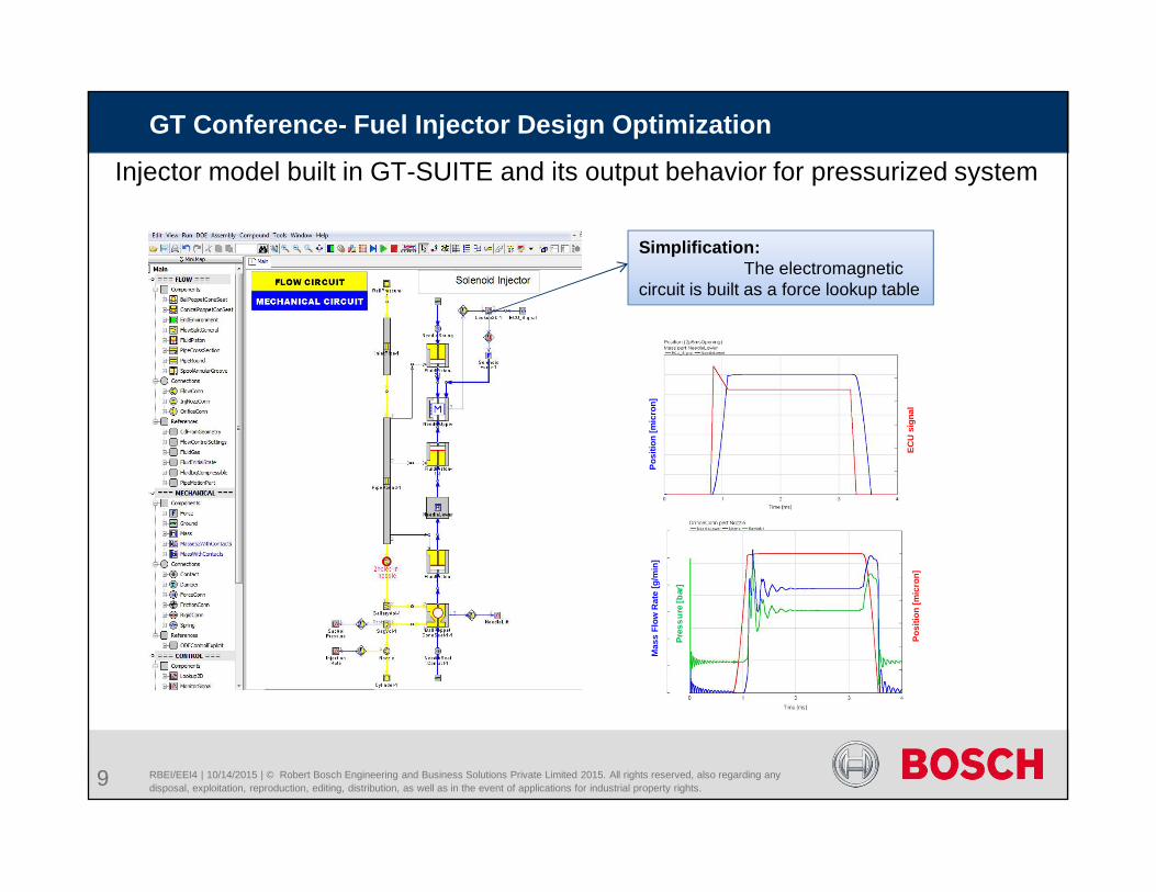
Injector model built in GT-SUITE and its output behavior for pressurized system
Simplification:The electromagnetic
circuit is built as a force lookup table
Posi
tion
[mic
ron]
ECU
sig
nal
Posi
tion
[mic
ron]
Mas
s Fl
ow R
ate
[g/m
in]
Pres
sure
[bar
]

RBEI/EEI4 | 10/14/2015 | © Robert Bosch Engineering and Business Solutions Private Limited 2015. All rights reserved, also regarding any disposal, exploitation, reproduction, editing, distribution, as well as in the event of applications for industrial property rights.
GT Conference- Fuel Injector Design Optimization
10
Simulation Test bench Simulation Test bench
Operating Pr bar 2.7 2.7 3 3
Needle Lift Microns 60 60 60 60
On time ms 2.5 2.5 2.5 2.5
Static Flow g/min 109 110 116.9 116
Dynamic Flow mg/Pulse 3.3 3.3 NA NA
Test bench and simulation results comparison
Sensitivity Analysis of 1D Simulation model
Flow rate variation with different operating pressure
Dynamic Flow rate variation with varying On time
Static flow rate variation with varying lift
2.5 2.7 2.9 3.1 3.3 3.5 3.7 3.9 4.1
Dyna
mic
Flo
w (m
g/St
roke
)
Operating Pr(bar)
Dynamic Flow @ varying On time
2.5ms60MicronLift 4ms60MicronLift
2.5ms80MicronLift 4ms80MicronLift
2.5ms100MicronLift 4ms100MicronLift
2 2.5 3 3.5 4 4.5 5
Dyn
amic
Flo
w (
mg/
Stro
ke)
OnTime(ms)
Linearity
`@2.7bar`3bar`4bar
2.5 2.7 2.9 3.1 3.3 3.5 3.7 3.9 4.1
Stat
icFl
ow(k
g/hr
)
Operating Pr(bar)
StaticFlow V/s Operating pressure
60MicronLift
80MicronLift
100MicronLift

RBEI/EEI4 | 10/14/2015 | © Robert Bosch Engineering and Business Solutions Private Limited 2015. All rights reserved, also regarding any disposal, exploitation, reproduction, editing, distribution, as well as in the event of applications for industrial property rights.
GT Conference- Fuel Injector Design Optimization
Instantaneous mass & Pressure inside sac Volume for low pressure system
Mas
s Fl
ow R
ate
[g/m
in]
Pres
sure
[bar
]
Sac Volume
Note: As the duty cycle is increased more fuel flows into the sac volume and gaseous volume fraction decreases and density increases
11
Popp
et L
ift [m
icro
ns]

0 2 4 6 8
Mas
s Flo
w(g
/min
)
Time (ms)
Test
Sim
RBEI/EEI4 | 10/14/2015 | © Robert Bosch Engineering and Business Solutions Private Limited 2015. All rights reserved, also regarding any disposal, exploitation, reproduction, editing, distribution, as well as in the event of applications for industrial property rights.
GT Conference- Fuel Injector Design Optimization
12
0 2 4 6 8 10
Mas
s Flo
w(g
/min
)
Time(ms)
Test
Sim
Engine speed N1
Test bench and simulation results comparison for low pressure systemP1 pressure
0 2 4 6 8 10
Mas
s Flo
w(g
/min
)
Time(ms)
Test
Sim
0 2 4 6 8
Mas
s Flo
w(g
/min
)
Time (ms)
Test
Sim
P2 pressure
Engine speed N2
Engine speed N1
Engine speed N2

RBEI/EEI4 | 10/14/2015 | © Robert Bosch Engineering and Business Solutions Private Limited 2015. All rights reserved, also regarding any disposal, exploitation, reproduction, editing, distribution, as well as in the event of applications for industrial property rights.
GT Conference- Fuel Injector Design Optimization
1 Motivation/Objective
2 Modeling approach
3 Simulation and Validation
4 DOE setup and Simulation
5 Summary
13

RBEI/EEI4 | 10/14/2015 | © Robert Bosch Engineering and Business Solutions Private Limited 2015. All rights reserved, also regarding any disposal, exploitation, reproduction, editing, distribution, as well as in the event of applications for industrial property rights.
GT Conference- Fuel Injector Design Optimization
14
DoE case set up
The goal of DoE is to identify the most
probable combination of the design
parameters, which provide maximum flow
The available maximum design parameter
values are used as boundary condition
A full factorial DoE type is used for DoE
settings
Parameters Min Max
No. of Holes 4 12
Hole Dia mm 0.2 1
Sac Volume mm^3 1.18 7
Lift microns 60 100

RBEI/EEI4 | 10/14/2015 | © Robert Bosch Engineering and Business Solutions Private Limited 2015. All rights reserved, also regarding any disposal, exploitation, reproduction, editing, distribution, as well as in the event of applications for industrial property rights.
GT Conference- Fuel Injector Design Optimization
15
DOE case setup results
2.5ms On time

RBEI/EEI4 | 10/14/2015 | © Robert Bosch Engineering and Business Solutions Private Limited 2015. All rights reserved, also regarding any disposal, exploitation, reproduction, editing, distribution, as well as in the event of applications for industrial property rights.
GT Conference- Fuel Injector Design Optimization
1 Motivation/Objective
2 Modeling approach
3 Simulation and Validation
4 DOE setup and Simulation
5 Summary
16

RBEI/EEI4 | 10/14/2015 | © Robert Bosch Engineering and Business Solutions Private Limited 2015. All rights reserved, also regarding any disposal, exploitation, reproduction, editing, distribution, as well as in the event of applications for industrial property rights.
GT Conference- Fuel Injector Design Optimization
17
Summary
Sensitivity analysis shows that the model is able to capture the flow
dynamics under varying operating conditions.
The supply pressure is varied during static and dynamic conditions and
compared with actual test bench measurements.
The low pressure system operation is well captured in the simulation
and test bench comparison results show a good match
DOE analysis provide the best possible combination of the design
parameters with given constraints
GT 1D hydraulic simulation helps in reducing the number of prototype
generated, testing time, cost and effort

RBEI/EEI4 | 10/14/2015 | © Robert Bosch Engineering and Business Solutions Private Limited 2015. All rights reserved, also regarding any disposal, exploitation, reproduction, editing, distribution, as well as in the event of applications for industrial property rights.
GT Conference- Fuel Injector Design Optimization
18
I would like to Thank the following people for their help during this work Pradeep R (GS/ESB11-IN) – RBIN
Shawn Harnish – Gamma Technologies
Bradford Lynch – Gamma Technologies

RBEI/EEI4 | 10/14/2015 | © Robert Bosch Engineering and Business Solutions Private Limited 2015. All rights reserved, also regarding any disposal, exploitation, reproduction, editing, distribution, as well as in the event of applications for industrial property rights.
GT Conference- Fuel Injector Design Optimization
19