fuels, furnaces & refractories -...
TRANSCRIPT

1
1
Fuels, Furnaces & Refractories
2. Furnaces
Dr. Eng. Yazan Al-Zain
Department of Industrial Engineering
University of Jordan
2
The Evolution of HeatFlame Temperature
• The temperature attained by the combustion of fuel depends not only on its calorific value, but also on the burning technique used.
• Example, coal normally burns in an open fire to give a temperature of the order of 1000 ºC, but if oxygen supply to it is restricted it may smoulder but continue to oxidize at about 200 ºC.
• Under more favorable conditions than normal, 2000 ºC might be achieved.

2
3
The Evolution of HeatFlame Temperature
• Factors affecting the temperature attained in the combustion of fuel are:
– Its calorific value.– The amount if diluent used “usually N2” admitted with O2. Under such
condition, about 3 quarters of the heat will be imparted to N2. The use of O2 enriched air “tonnage oxygen; 99%” will increase the temperatures reached.
– Temperature of fuel and air prior to combustion: sensible heat in the reactants should be added to the C.V. in assessing the total heat attainable in the combustion products.
– The rate at which the reactions take place: the higher the rate the lower the losses and the higher the temperature attained. Rate can be increased by suitable design of the burner (rapid mixing of fuel and O2) or by increasing the reactivity of the fuel.
4
The Evolution of HeatFlame Temperature
• Example 4: calculate the ideal flame temperature for the combustion of methane by air preheated at 600 C. The heat of oxidation is given by: CH4+ 2O2 = CO2 + 2H2O; ΔH = -191,800 cal.

3
5
The Evolution of HeatFlame Temperature
• Example 4:
6
The Evolution of HeatFlame Temperature
• In case there were excess amount of air, temperature will be modified.
• Example 5: If in the previous example the products were to carry an excess of 2% by volume of unburned oxygen, what would the adiabatic flame temperature then be?

4
7
The Evolution of HeatFlame Temperature
• Example 5:
8
The Evolution of HeatFlame Temperature
• Example 6: If in the previous example, 5% of the total heat available is deemed to be lost during combustion, how would the temperature be affected?

5
9
The Evolution of HeatAvailable Heat
• The advantages of achieving high flame temperatures become clearif we consider the concept of available heat. This is simply an expression of the 2nd law of thermodynamics.
• Example, if the burden in a furnace is to be held at 1600 ºC, a flame at 1700 ºC would be useful only in so far as it could yield up heat as it was itself cooled down to 1600 ºC, i.e. only about one-seventeenth of its heat content at 1600 ºC. A flame at 2000 ºC would have one-fifth of its heat available at 1600 ºC so that only about one-third of the fuel would be required to have the same effect as with the 1700 ºC flame.
10
Principles of Burner Design
• The release of potential energy of fuel by combustion with air requires several stages:
– Mixing of air and fuel.– Ignition of the mixture. – Chemical reaction.– Disposal of products of combustion from the reaction site so that fresh
reactants are available.
• Except mixing of air and fuel, all other stages are extremely fast such that it is said that if fuel and air are mixed, fuel is burnt. Accordingly mixing is the slowest step in the process of combustion.

6
11
Principles of Burner DesignThe Burner
• A burner is a mechanical device that:
– Supplies required amount of fuel and air.– Creates condition for rapid mixing of fuel and air.– Produces a flame which transfers thermal energy to furnace and charge.
• In oil burners, oil is atomized into a fine spray by a spray nozzle and air is supplied for combustion in the spray chamber. Alternatively oil may be atomized by high speed air to produce a fine dispersion of droplets into air.
• There are liquid fuel and gaseous fuel burners.
– In liquid fuel burner, oil is heated and atomized either mechanically or by high speed gaseous jet. In mechanical methods oil is atomized by means of a rotating disc or cup (See Figure next slide).
– Mechanical atomization produces wider spray of oil and wide flame area with uniform droplet size.
12
Principles of Burner DesignThe Burner
Figure 2-1: Rotary cup burner.

7
13
Principles of Burner DesignThe Burner
• There are liquid fuel and gaseous fuel burners.
– A gaseous fuel burner could either be of premixed type or diffusion type.
• In a pre‐mixed type gas and air are mixed prior to passing through the nozzle.
• In diffusion type fuel and some amount of air is mixed and the mixture is passed through the burner, while rest air for combustion is supplied in the furnace chamber.
• Combustion of fuel is controlled by the rate of mixing of air and fuel. In these burners small portion of air is mixed with fuel as primary air and the rest amount, known as secondary air is supplied in the furnace.
14
Principles of Burner DesignCharacteristic Features of Jet
• A jet is produced when a fluid is discharged through the nozzle. In the jet the velocity of the fluid is accelerated.
• Free jet is produced when the fluid is discharged in the surrounding with no confinement. A jet is said to be confined when the fluid is discharged in the container.
• The characteristic feature of the jet (whether free of confined) is that it spreads due to the difference in the density of the jet and the surrounding.
• For any downstream axial distance, the maximum velocity is at the centre and minimum at the periphery such that a parabolic profile is developed as shown in Figure 2-2.

8
15
Principles of Burner DesignCharacteristic Features of Jet
Figure 2-2: Spreading of a jet into the surrounding.
16
Principles of Burner DesignRule of Primary Air
• In the design of burner for gaseous fuel it is important to design the primary air depending on the requirement.
• Since the amount of air is many times greater than the fuel, momentum flux within the jet is controlled by the primary air, where the primary air:
– Controls the fuel /air mixing rate.– Assists in stabilizing the jet and to control circulation.

9
17
Principles of Burner DesignDegree of circulation
• Circulation sets in when the secondary air is mixed completely with the fuel, and the degree of circulation indicates complete mixing of fuel with air.
• In confined gets, absence of circulation results in a tendency for the flame to expand until it impinges into the furnace walls of load.
• Hot gases will be in direct contact with the refractory brick which may result in failure.
• The circulating gases provide a “cushion” of cooler inert flue gases which prevents direct impingement of flame.
18
Principles of Burner DesignSelection of Burner
• The space occupied by the fuel and the products of combustion varies considerably with the burner design, upstream pressures and flow rates.
• Gaseous fuel burners can be designed to release heat as high as 110 x 106 K.cal / hr.m2 of combustion volume.
• Gaseous fuel supply, air supply and control valves form the essential components of a gaseous fuel burner. Further a burner designed for one particular fuel is not suitable for other.

10
19
The Combustion of FuelSolid Fuel Beds (Coke)
• The most common solid fuel is carbon in the form of coal or coke.
• The combustion of coke occurs in two stages:
[1] C + O2 = CO2 ΔH = -94,200 cal, until all O2 is consumed.
[2] C + CO2 = 2CO ΔH = 40,200 cal, until CO2 is consumed.
• Since reaction [2] is endothermic, it must be inhibited as far as possible by using fuel with low effective reactivity (to CO2).
– Done by using fuel with low effective reactivity (to CO2).– And short fuel bed.
20
Figure 2-3: Gas analysis and temperature distribution in coke beds. (a) very unreactive fuel and (b) very reactive fuel.
The Combustion of FuelSolid Fuel Beds (Coke)

11
21
The Combustion of FuelOil
• Oil maybe burned by: being broken into fine droplets which are injected into hot air so that they evaporate while burning.
– Heavy oil is warmed to suitably low viscosity and “atomized”.
– Atomization can be done mechanically by means of: (1) a rotating disk, (2) high pressure ejection from a fine orifice or (3) by entrainment in a blast of air or steam.
• Oil is being used in large amounts in open hearth in steel making and in other metallurgical applications.
• Oil is injected into the hot furnace accompanied by a steam of pre-heated air. The droplets immediately evaporate, and most of the combustion occurs as vapor phase reaction.
22
The Combustion of FuelGas
• There are two methods of burning gaseous fuels:
– The gas and air maybe pre-mixed cold and burned at the end of the pre-mixing chamber.
– Gas and air flow into the furnace separately and mix together ascombustion proceeds.
• Gas is usually delivered at a low pressure and air maybe drawn into the furnace through ports beside each burner.

12
23
Furnace Construction
• Furnaces usually have a cast iron or steel frame and a refractory brick wall and lining.
• Thermal expansion in brickwork must be accommodated, usually by leaving space between bricks during building.
– Otherwise, the frames will become distorted because the expansion of the refractory is 3 or 4 times the maximum elastic strain in steel.
• Metallic components can also be used in parts such as doors and door frames, grates and burners. These parts should be water-cooled (when temperatures are too high) or air-cooled (for moderate temperatures).
• Sheet steel around brickwork can minimize gas leakage and help in low temperature insulation.
24
Furnace Construction
• Special tools are utilized for charging and discharging the furnace; e.g. the use of buckets for charging the blast furnace and the use of ladles that receive the molten metal.
• Refractories are expandable but costly, so they should be well chosen and well laid with suitable refractory cements.
• The success of furnace design is best measured by:
– The rate at which the furnace can consume fuel.
– The efficiency with which it transfers its energy to the stock.
– The amount of fuel it can consume before its worn out.

13
25
Classification of Furnaces
• The present discussion recognizes three major categories of metallurgical furnaces:
– The crucible furnace.
– The hearth furnace.
– The shaft furnace.
• These furnaces are distinguished mainly by shape.
• Some furnaces can be included in more than one group; e.g. retorts are distinguished by their volatile products
26
Classification of FurnacesPhysical Processing

14
27
Classification of FurnacesClass 1 – Crucible Furnaces
• Used in foundries for melting small batches of ferrous and nonferrous metals.
• The charge is melted in a refractory or metal pot which maybe fired externally by coal, coke, gas or oil, or internally by gas or oil burners.
• Small units are fixed and the pot must be removed for pouring, while larger units are tilting furnaces from which the pot need not beremoved and therefore suffers less mechanical and thermal damage.
• Crucible furnaces vary from primitive pots through a whole range of improvements, each involving more control over combustion.
28
Classification of FurnacesClass 1 – Crucible Furnaces
Figure 2-4: A crucible furnace.

15
29
Classification of FurnacesClass 1 – Crucible Furnaces
• Distribution of heat before melting is mainly by natural convection within the crucible, and is usually inefficient.
• In some modern furnaces the crucible rotates on an inclined axiswhile a gas or oil flame either swirls round the outside or plays directly on the charge; e.g. induction melting furnaces.
• The stock may, if necessary, be isolated from the furnace gases in most designs of crucible furnaces.
• With induction heating, any atmosphere can be imposed and the whole melting and casting operation can be carried out in vacuumon moderate scale.
• Max. charge is about 100 kg for fixed furnaces and 5000 kg for tilting furnaces.
30
Classification of FurnacesClass 1 – Crucible Furnaces
• The induction furnace is composed of a refractory container, capable of holding the molten bath, which is surrounded by a water-cooled helical coil connected to a source of alternating current.
• The induction of the electrical current in a conductive metal (charge) placed within a coil of conductor carrying electrical current is known as electromagnetic induction of secondary current.
• The alternating current applied to the coil produces a varying magnetic field which is concentrated within the helical coil. This magnetic field passing through the charge induces secondary current in the charge piece. The current circulating in the charge produces electrical losses which heat the charge and eventually melt it.
Figure 2-5: A schematic diagram of an induction furnace

16
31
Classification of FurnacesClass 2 – Hearth Furnaces
• Includes a wide range of fixed, tilting and rotating furnaces and kilns fired with all fuels.
– Used for roasting, melting, reheating and many purposes.
• The charge on the floor or hearth of the furnace is heated by convection and radiation from the flame (or electrical source).
• Originally, bigger hearths were used for roasting furnaces whilesmaller hearths for melting.
– The primitive type used a coal-fired box, which was later replaced by gas or oil burners.
– Further development led to the use of regenerators for preheating the gas and air with heat from waste gases; e.g. regenerative open hearth steelmaking furnaces (the traditional glass tank is of a similar design).
32
Classification of FurnacesClass 2 – Hearth Furnaces
Figure 2-6: A Hearth furnace.

17
33
Classification of FurnacesClass 2 – Hearth Furnaces
Figure 2-7: Open hearth steelmaking furnace, where A. Gas and air enter, B. Pre-heated chamber, C. Molten pig iron, D. Hearth E. Heating chamber (cold) F. Gas and air exit
34
Classification of FurnacesClass 2 – Hearth Furnaces
• Essentially the production of steel from pig iron by any process consists of burning out the excess carbon and other impurities present in the iron.
• One difficulty in the manufacture of steel is its high melting point, about 1370 ºC, which prevents the use of ordinary fuels and furnaces.
• To overcome this difficulty the open-hearth furnace was developed; this furnace can be operated at a high temperature by regenerative preheating of the fuel gas and air used for combustion in the furnace.
• In regenerative preheating, the exhaust gases from the furnace are drawn through one of a series of chambers containing a mass of brickwork and give up most of their heat to the bricks.
• Then the flow through the furnace is reversed and the fuel and air pass through the heated chambers and are warmed by the bricks. Through this method open-hearth furnaces can reach temperatures as high as 1650 ºC.

18
35
Classification of FurnacesClass 2 – Hearth Furnaces
• The furnace is charged with a mixture of pig iron (either molten or cold), scrap steel, and iron ore that provides additional oxygen.
• Limestone is added for flux and fluorspar to make the slag more fluid.
• The proportions of the charge vary within wide limits, but a typical charge might consist of 56,750 kg of scrap steel, 11,350 kg of cold pig iron, 45,400 kg of molten pig iron, 11,800 kg of limestone, 900 kg of iron ore, and 230 kg of fluorspar.
• After the furnace has been charged, the furnace is lighted and the flames play back and forth over the hearth as their direction is reversed by the operator to provide heat regeneration.
36
Classification of FurnacesClass 2 – Hearth Furnaces
• Chemically the action of the open-hearth furnace consists of lowering the carbon content of the charge by oxidization and of removing such impurities as silicon, phosphorus, manganese, and sulphur, which combine with the limestone to form slag.
• These reactions take place while the metal in the furnace is at melting heat, and the furnace is held between 1540 and 1650 ºC for many hours until the molten metal has the desired carbon content.
• The melt is usually tested by withdrawing a small amount of metal from the furnace, cooling it, and subjecting it to physical examination or chemical analysis.
• When the carbon content of the melt reaches the desired level, the furnace is tapped through a hole at the rear. The molten steel then flows through a short tube to a large ladle set below the furnace at ground level.
• From the ladle the steel is poured into cast-iron molds that form ingots usually about 1.5 m long and 48 cm square.

19
37
Classification of FurnacesClass 2 – Hearth Furnaces (Kilns)
• Kilns are an essential part of the manufacture of all ceramics, which require heat treatment, often at high temperatures.
• During this process, chemical and physical reactions occur that permanently alter the unfired body.
• In the case of pottery, clay materials are shaped, dried and then fired in a kiln.
• The final characteristics are determined by the composition and preparation of the clay body, by the temperature at which it is fired, and by the glaze that may be used.
• Types of kilns include: Pit Kilns, Beehive Kilns, Climbing Kilns, Natural Gas Kilns, and Electric Kilns.
38
Classification of FurnacesClass 2 – Hearth Furnaces (Kilns)
• Pit Kilns: earliest kilns were nothing more than a shallow 'pit' dug in the ground. Pottery was loose stacked on top of each other.
– Combustible materials were placed around and above the pottery and the fire was allowed to burn down. After cooling, the pots were cleaned of the ash and residue and were then used.
– Pots fired in this way were very fragile and porous due to the low temperatures possible in such a firing (550 -650 ºC). At this low temperature glazing is not possible and was not discovered until much later.
– Advantages: its relative ease of 'construction' and low cost.
– Disadvantages: the low temperature limitations and the fragility of the ware.

20
39
Classification of FurnacesClass 2 – Hearth Furnaces (Kilns)
• Beehive Kilns: in these kilns the fuel and fire are below the ware, the insulation, in the form of an arch is on top, retaining the heat better.
– The pots are stacked within this chamber allowing greater retention of heat. The enclosing of the kiln presents a problem; oxygen access is restricted, and, without ventilation, this kiln will not burn properly.
– Therefore, a hole at the top of the kiln, known as a flue, must be included in the beehive design.
– The damper is the device that regulates the size of the opening of the flue. Oxygen does not enter the flue. Rather, it exits the flue by nature of the tendency of heat to rise.
– As the fire burns, and the kiln gets hotter, the hot air rises and leaves the kiln through the flue. Meanwhile, cool air enters the bottom at the firebox.
• Natural Gas Kilns: similar to beehive kilns except that fuel used is gas instead of coal (or coke) and isolation is better due to better insulating bricks.
40
Classification of FurnacesClass 2 – Hearth Furnaces (Kilns)
• Electric Kilns: instead of a burning fuel, these operate by radiant heat generated from an electrical current passing through coiled wires (just like a toaster).
– Since these kilns have no fireboxes and no burning inside, they have no need of a damper or flue, since no draft in necessary.
– What they share with the fuel-burning kilns is insulation and a loading area.
– Most modern electric kilns are equipped with electronic shut off devices, called kiln sitters, to monitor the firing process.

21
41
Classification of FurnacesClass 2 – Hearth Furnaces (Kilns)
Electric kiln
Figure 2-8: Various types of kilns.
42
Classification of FurnacesClass 3 – Shaft Furnaces
• Used for melting, smelting, and calcining or roasting.
• They are either cylindrical or rectangular shafts through which the solid charge flows down under gravity into the space vacated by the discharge of solids or liquids.
• Usually the fuel (coke) is included in the charge and is preheated in descent by the ascending stream of hot gas (CO + N2). Hot air is blown through nozzles called “Tuyeres”
• The “Iron Blast Furnace” is the most highly developed shaft furnace and can operate very efficiently not only as a heating unit but also as a reaction chamber.
22
43
Classification of FurnacesClass 3 – Shaft Furnaces
7
1
6
2
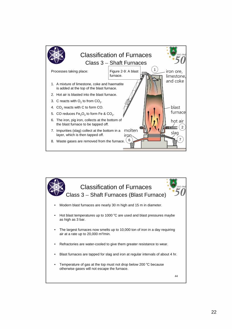
Processes taking place:
1. A mixture of limestone, coke and haematiteis added at the top of the blast furnace.
2. Hot air is blasted into the blast furnace.
3. C reacts with O2 to from CO2.
4. CO2 reacts with C to form CO.
5. CO reduces Fe2O3 to form Fe & CO2.
6. The iron, pig iron, collects at the bottom of the blast furnace to be tapped off.
7. Impurities (slag) collect at the bottom in a layer, which is then tapped off.
8. Waste gases are removed from the furnace.
Figure 2-9: A blast furnace.
44
Classification of FurnacesClass 3 – Shaft Furnaces (Blast Furnace)
• Modern blast furnaces are nearly 30 m high and 15 m in diameter.
• Hot blast temperatures up to 1000 ºC are used and blast pressures maybe as high as 3 bar.
• The largest furnaces now smelts up to 10,000 ton of iron in a day requiring air at a rate up to 20,000 m3/min.
• Refractories are water-cooled to give them greater resistance to wear.
• Blast furnaces are tapped for slag and iron at regular intervals of about 4 hr.
• Temperature of gas at the top must not drop below 200 ºC because otherwise gases will not escape the furnace.

23
45
Classification of FurnacesClass 3 – Shaft Furnaces (The Cupola)
A simple melting furnace (up to 4 m in height) for cast iron usually working on cold but hot blast is sometimes used, process includes:
1. The furnace is filled with layers of coke and ignited with torches. When the coke is ignited, air is introduced to the coke bed through tuyeres.
2. When the coke is very hot, solid pieces of metal are charged into the furnace through an opening in the top. The metal is alternated with additional layers of fresh coke. Limestone is added to act as a flux.
3. As the heat rises within the stack the metal is melted. It drips down through the coke bed to collect in a pool at the bottom, just above the bottom doors.
4. Rest is similar to blast furnace.Figure 2-10: A cupola furnace.
46
Classification of FurnacesClass 4 – Retorts
• In the production of gas from coal in a few extraction processes the reactions leading to a gaseous product are carried out in a retort.
• A retort was a narrow vessel open only at one end, and the process was always a batch process. These retorts have disappeared in favor of a more continuous system:
– In continuous systems, the charge is passed down through a narrow chamber in which the reactions takes place and from which the volatile product can be drawn without contamination with air.

24
47
Classification of FurnacesClass 4 – Retorts
The Lurgi gasifier is one type, operation includes:
1. The Lurgi gasifier is a pressurized, dry-ash, moving bedgasifier that produces gas from lump coal, steam, and oxygen as an oxidant.
2. A high ratio of steam to oxygen helps moderate the temperature such that the ash does not melt, but rather is removed as dry ash.
3. Coal enters the top of the gasifier through a lock hopper and is handled by a rotary distributor as it begins its descent through the gasifier. Steam and oxygen enter from the bottom, while ash is removed at the bottom by a rotating grate and lock hopper.
4. A top temperature of about 550 ºC and bottom temperature of about 1,000 ºC creates a temperature gradient in the gasifier. Exiting raw gas at up to 550 ºC is cooled and quenched using recycle water to condense tars and oils. A water jacket cools the gasifier vessel and generates part of the steam needed by the gasifier.
Figure 2-11: Lurgi gasifier.
48
Classification of FurnacesClass 5 – Converters
• Used in steelmaking, copper production and to a limited extent in other nonferrous processes.
• The top blown converter is the most famous type, used for steelmaking by the so-called basic oxygen process (BOS).
• The BOS is self-sufficient in energy.
• The primary raw materials for the BOS are 70-80% liquid hot metal from the blast furnace and the balance is steel scrap.
• Oxygen (>99.5% pure) is "blown" into the BOS at high velocities. It oxidizes the carbon and silicon contained in the hot metal liberating great quantities of heat which melts the scrap. The post combustion of carbon monoxide as it exits the vessel also transmits heat back to the bath.

25
49
Classification of FurnacesClass 5 – Converters
• In the BOS, steel is refined in a pear-shaped furnace that tilts sideways for charging and pouring.
• After the furnace has been charged, an oxygen lance is lowered into it. The water-cooled tip of the lance is usually about 2 m above the charge although this distance can be varied according to requirements.
• Thousands of cubic meters of oxygen are blown into the furnace at high speeds. The oxygen combines with carbon and other unwanted elements and starts a high-temperature reaction that rapidly burns out impurities from the pig iron and converts it into steel.
• The refining process takes 50 min or less; approximately 275 metric tons of steel can be made in an hour.
Figure 2-12: A top blown converter .
50
Classification of FurnacesClass 6 – Sintering Machines
• Sintering (after compaction) of metallic powders is done to: (1) bond individual grains into a solid mass, (2) increase density, and (3) reduce or eliminate porosity.
• Sintering is conducted in furnaces called sintering machines.
• In steelmaking, raw materials include fine iron ore, coke and fine limestone and sand (SiO2).
• Raw materials are then mixed to produce a homogeneous mixture. This mixture is then placed on a rotating disk and sprayed with water to form granules of this homogeneous mixture.
• This granulated material is charged onto a continuous horizontal travelling grate of the Dwight-Lloyd sintering machine to form a bed of 400-600 mm deep and the top bed is ignited by oil or gas burners.
• Air is continuously drawn downward throughout the length of the grate by suction fan so that the flame front gradually travels down through the bed of the sinter mix.

26
51
Classification of FurnacesClass 6 – Sintering Machines
• Temperature of the bed raises to 1250 – 1600 ºC, depending on the amount and type of fuel used.
• The iron ore is finally reduced to FeO and then combine with SiO2 to form fayalite (2FeO.SiO2). Fayalite melts at 1290 ºC in the bed and helps the solid particles in their bonding into a big and strong agglomerate.
• Most of heat produced by combustion is consumed by drying, preheating and calcinations of materials in the lower layer of the bed.
• When the combustion zone reaches the bottom layers of the mix, outgoing combustion gases attain maximum temperature indicating that the sintering of the mix is complete.
• The sinter cakes discharged from the grate are broken to suitable sizes and screened.
52
Classification of FurnacesClass 6 – Sintering Machines
• The flux addition improves the physical quality of the sinter. It also reduces the iron content of the blast furnace slag as iron in the sinter is in more reducible form (FeO).
Figure 2-14: Dwight-Lloyd sintering machine.
Figure 2-13: Flow chart of the sintering process.

27
53
Classification of FurnacesClass 7 – Some Miscellaneous Furnaces
(a) Suspension Roasting: applied to the conversion of sulfides to oxides or sulfates when the mineral has been very finely ground in the concentration process. The sulfide particles pass down through a heated chamber against a current of air, burning as they fall and providing the heat necessary for the continuance of the process.
- This type of process suggests fluidized bed techniques in which gases and fine powders react while the latter is being carried along supported in the turbulent stream of the former.
- This technique is well established in chemical engineering, petroleum technology and extraction metallurgy.
- Limitation: fine particles of many minerals tend to sinter together at quite moderate operating temperatures and the critical particle size distribution necessary for fluidization cannot always be maintained.
54
Classification of FurnacesClass 7 – Some Miscellaneous Furnaces
(b) Soaking pits: developed from simple pits in the ground in which steel ingots were allowed to cool slowly, smothered in ashes.
- Modern soaking pits are gas fired chambers each holding a number of ingots and still charged and discharged thorough the top.
- Heating is mainly by convective transfer from the hot gases.
- Soaking pits aims at heat treating the ingots or homogenization of the alloys.
Figure 2-15: Soaking pit.

28
55
Classification of FurnacesClass 7 – Some Miscellaneous Furnaces
(c) Forced air circulation furnaces: they are similar to soaking pits in so far as many of them are charged and discharged through the top and heating is by convection.
- A powerful fan keeps the air circulating first over the heaters and then through the burden (plates).
- Burden should be loosely packed to allow good distribution of hot air over its surface.
- Temperature do not go above 700 ºC and the efficiency of the furnace is determined largely by its insulation.
Figure 2-16: pit type air circulation furnace.
56
Classification of FurnacesClass 7 – Some Miscellaneous Furnaces
(d) Salt bath furnaces: used for heating machined metallic parts out of contact with air, and commonly used for heat treatment of steel.
- Salts used are mixtures of nitrides, chlorides or sometimes cyanides.
- Nitrides cannot be used above 500 ºC as they become unstable. Chlorides become volatile above 800 ºC and cannot be used above 900 ºC, except barium chloride which is stable at temperatures higher than 1350 ºC.
- Glasses and slags can be used at very high temperatures but are rather viscous, and more fluid compositions are usually rather reactive toward either metal or the containing vessel.
Figure 2-17: salt bath furnace.

29
57
Classification of FurnacesClass 7 – Some Miscellaneous Furnaces
(d) Salt bath furnaces: used for heating machined metallic parts out of contact with air, and commonly used for heat treatment of steel.
- These baths maybe in the form of simple crucible furnaces fired with gas or oil, the salt being contained permanently in the crucible which would be usually an alloy cast iron pot.
- Alternatively, the salt maybe heated by passing an electric current through it between two electrodes.
- Heat transfer to the stock is by natural convection. This is very rapid and much faster than from a gaseous atmosphere at the same temperature, mainly because of the higher specific heat of the fluid.
Figure 2-17: salt bath furnace.
58
Classification of FurnacesClass 7 – Some Miscellaneous Furnaces
(e) Electrolytic cells: as those used for the extraction of Al are also heated by the passage of an electric current through a molten solution of salt.
- In this case, alumina is dissolved in cryolite (Na3AlF6) and the bath operates at 900 ºC on the current used for electrolysis.
- Heat transfer is very rapid.
- The efficiency depends on the insulation provided and on other design features of the cell. Figure 2-18: Aluminum electrolysis.

30
59
Laboratory Furnaces
• Laboratory furnaces are of all types and are designed on the same principles as industrial furnaces.
• They differ from these only in scale and in the degree of temperature controlwhich may be necessary.
• Design is difficult as sometimes the means of charging and discharging, control of atmosphere and the sitting of probes may have to be met.
• Usually are electric furnaces as these are cleanest and easiest to control.
• Most electric furnaces are resistance heated, using resistor materials such as platinum, rhodium, tungsten, tantalum and silicon carbide.
• These resistors should be protected against chemical attack and thermal shock.
60
Laboratory Furnaces
• Induction furnaces are very useful for high temperature applications, being rapid in action, clean and ideal for vacuum or controlled temperature atmosphere operations.
• These furnaces are suitable for making small melts of steel and other alloys.
• Refractories could also be of all kinds but vitreous silica and aluminous porcelain meet the need of a high proportion of cases.
• Beyond 1350 ºC, refractory ware must be carefully chosen from sillimanite, mullite, and alumina or special refractories like zirconia and thoria.

31
61
Laboratory Furnaces
• Ability to estimate the power required to attain the desired temperature requires some good experience, making the design of a laboratory furnace a difficult process.
– Power input depends on the size of space to be heated and the working temperature and the degree to which the furnace can be insulated.
– As a guide,, it maybe said that under favorable conditions a 25 mm diameter tube furnace at 1000 ºC would require about 0.5 kW while a 75 mm diameter furnace at 1500 ºC would need 3 or 4 kW.
• Losses due to convection must be avoided, probably best by arranging that the hot chamber be fairly well filled by stock.