fuji igbt modules for solar inverterver4).pdf · simple schematics of solar inverter inverter...
TRANSCRIPT

© Fuji Electric Co., Ltd. All rights reserved. 1 Jan. 2015 MT5F27333
Device Application Technology Dept. Semiconductor Sales Div.
Global Sales Group
Fuji IGBT Modules for Solar Inverter

© Fuji Electric Co., Ltd. All rights reserved. 2 Jan. 2015 MT5F27333
n Topology in solar inverter
n Fuji IGBT modules for solar inverter
n Fuji solution in Gate Driver Unit (GDU)
n Fuji 2 level topology solution
n Fuji 3 level topology solution - Stack
Table of contents

© Fuji Electric Co., Ltd. All rights reserved. 3 Jan. 2015 MT5F27333
Simple schematics of solar inverter
Transformer Inverter Solar panel
AC DC
~
Load
Grid
■Feature of solar inverter: High efficiency, High reliability.
General inverter Solar inverter
Input voltage AC (Ex. 400V±10%) DC 400~1000V
Output frequency Ex. 0.5~120Hz 50 / 60Hz
Efficiency 90~95% > 95%
Overload 150~200% 100~120%
Device (ex. 30kW) 1200V / 150A 1200V / 200A
Filter AC
© Fuji Electric Co., Ltd. All rights reserved. 4 Jan. 2015 MT5F27333
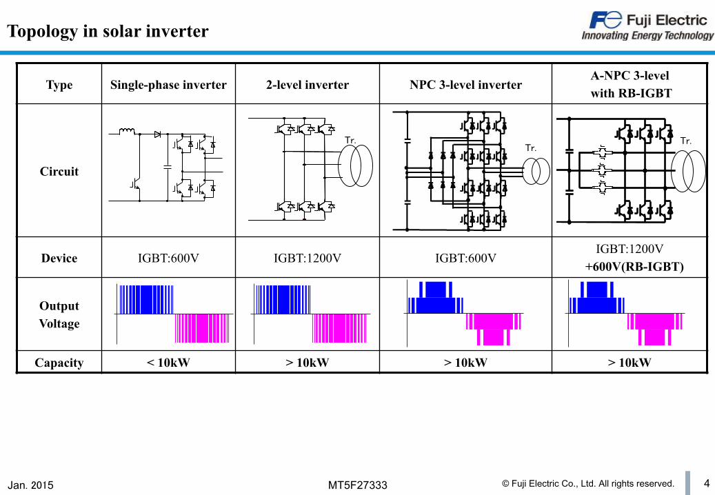
Type Single-phase inverter 2-level inverter NPC 3-level inverter A-NPC 3-level with RB-IGBT
Circuit
Device IGBT:600V IGBT:1200V IGBT:600V IGBT:1200V
+600V(RB-IGBT)
Output Voltage
Capacity < 10kW > 10kW > 10kW > 10kW
Topology in solar inverter
Tr. Tr.
Tr.
© Fuji Electric Co., Ltd. All rights reserved. 5 Jan. 2015 MT5F27333
n Topology in solar inverter
n Fuji IGBT modules for solar inverter
n Fuji solution in Gate Driver Unit (GDU)
n Fuji 2 level topology solution
n Fuji 3 level topology solution - Stack
Table of contents
© Fuji Electric Co., Ltd. All rights reserved. 6 Jan. 2015 MT5F27333
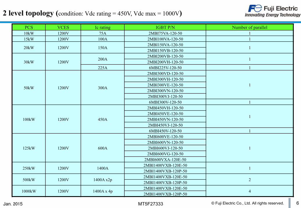
2 level topology (condition: Vdc rating = 450V, Vdc max = 1000V)
PCS VCES Ic rating IGBT P/N Number of parallel 10kW 1200V 75A 2MBI75VA-120-50 1 15kW 1200V 100A 2MBI100VA-120-50 1
20kW 1200V 150A 2MBI150VA-120-50
1 2MBI150VB-120-50
30kW 1200V 200A
2MBI200VB-120-50 1
2MBI200VH-120-50 225A 6MBI225V-120-50 1
50kW 1200V 300A
2MBI300VD-120-50
1 2MBI300VH-120-50 2MBI300VE-120-50 2MBI300VN-120-50 2MBI300VJ-120-50 6MBI300V-120-50 1
100kW 1200V 450A
2MBI450VH-120-50
1 2MBI450VE-120-50 2MBI450VN-120-50 2MBI450VJ-120-50 6MBI450V-120-50 1
125kW 1200V 600A
2MBI600VE-120-50
1 2MBI600VN-120-50 2MBI600VJ-120-50 2MBI600VG-120-50
2MBI600VXA-120E-50
250kW 1200V 1400A 2MBI1400VXB-120E-50
1 2MBI1400VXB-120P-50
500kW 1200V 1400A x2p 2MBI1400VXB-120E-50
2 2MBI1400VXB-120P-50
1000kW 1200V 1400A x 4p 2MBI1400VXB-120E-50
4 2MBI1400VXB-120P-50

© Fuji Electric Co., Ltd. All rights reserved. 7 Jan. 2015 MT5F27333
Fuji IGBT module for solar inverter - 2 level topology
Standard 1in1/2in1
PrimePACKTM
1in1 62mm
62mm
80mm
45mm
注:PrimePACKTM は Infineon Technology 社の登録商標です。
EconoPACKTM+
Dual XT
Note: EconoPACKTM+ and PrimePACKTM are registered trademarks of Infineon Technology AG, Germany. Size:172 x 89 x 38mm
Size:250 x 89 x 38mm
M271
M272 M629
Size:150 x 162 x 17mm
M254
M260 M254
Size:150 x 62 x 17mm
© Fuji Electric Co., Ltd. All rights reserved. 8 Jan. 2015 MT5F27333
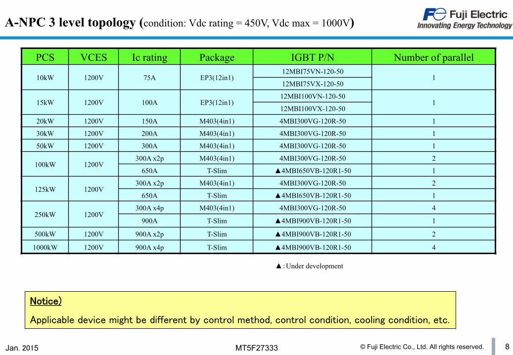
A-NPC 3 level topology (condition: Vdc rating = 450V, Vdc max = 1000V)
▲:Under development
PCS VCES Ic rating Package IGBT P/N Number of parallel
10kW 1200V 75A EP3(12in1) 12MBI75VN-120-50
1 12MBI75VX-120-50
15kW 1200V 100A EP3(12in1) 12MBI100VN-120-50
1 12MBI100VX-120-50
20kW 1200V 150A M403(4in1) 4MBI300VG-120R-50 1
30kW 1200V 200A M403(4in1) 4MBI300VG-120R-50 1
50kW 1200V 300A M403(4in1) 4MBI300VG-120R-50 1
100kW 1200V 300A x2p M403(4in1) 4MBI300VG-120R-50 2
650A T-Slim ▲4MBI650VB-120R1-50 1
125kW 1200V 300A x2p M403(4in1) 4MBI300VG-120R-50 2
650A T-Slim ▲4MBI650VB-120R1-50 1
250kW 1200V 300A x4p M403(4in1) 4MBI300VG-120R-50 4
900A T-Slim ▲4MBI900VB-120R1-50 1
500kW 1200V 900A x2p T-Slim ▲4MBI900VB-120R1-50 2
1000kW 1200V 900A x4p T-Slim ▲4MBI900VB-120R1-50 4
Notice)
Applicable device might be different by control method, control condition, cooling condition, etc.
© Fuji Electric Co., Ltd. All rights reserved. 9 Jan. 2015 MT5F27333
T-Slim PrimePACKTM
9
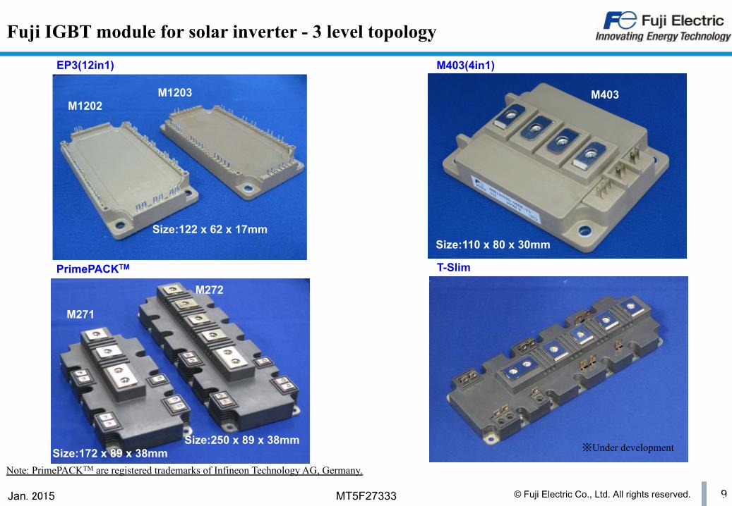
Fuji IGBT module for solar inverter - 3 level topology
※Under development Size:172 x 89 x 38mm Size:250 x 89 x 38mm
M271
M272
M403
Size:110 x 80 x 30mm
M1202
Size:122 x 62 x 17mm
EP3(12in1) M403(4in1)
Note: PrimePACKTM are registered trademarks of Infineon Technology AG, Germany.
M1203

© Fuji Electric Co., Ltd. All rights reserved. 10 Jan. 2015 MT5F27333
Fuji IGBT module for solar inverter - Standard 2in1
IGBT P/N Current Voltage Package Equivalent circuit
2MBI**VA-120-50 75A, 100A, 150A 1200V
2MBI**VB-120-50 150A, 200A 1200V
2MBI**VD-120-50 300A, 400A 1200V
2MBI**VE-120-50 300A, 450A, 600A 1200V
2MBI**VH-120-50 200A, 300A, 450A 1200V
Stan
dard
2in
1
Feature ü Low power dissipation with V-silicon chipset ü Extra thermal design (Tjmax = 175℃ repetitive guarantee)
M263
M274
M275
M275
M276
© Fuji Electric Co., Ltd. All rights reserved. 11 Jan. 2015 MT5F27333
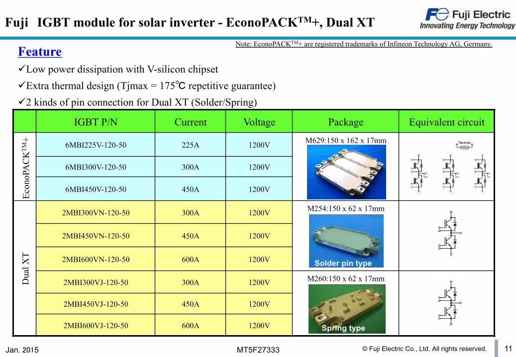
Fuji IGBT module for solar inverter - EconoPACKTM+, Dual XT
IGBT P/N Current Voltage Package Equivalent circuit
6MBI225V-120-50 225A 1200V M629:150 x 162 x 17mm
6MBI300V-120-50 300A 1200V
6MBI450V-120-50 450A 1200V
2MBI300VN-120-50 300A 1200V M254:150 x 62 x 17mm
2MBI450VN-120-50 450A 1200V
2MBI600VN-120-50 600A 1200V
2MBI300VJ-120-50 300A 1200V M260:150 x 62 x 17mm
2MBI450VJ-120-50 450A 1200V
2MBI600VJ-120-50 600A 1200V
Econ
oPA
CK
TM+
Feature ü Low power dissipation with V-silicon chipset ü Extra thermal design (Tjmax = 175℃ repetitive guarantee) ü 2 kinds of pin connection for Dual XT (Solder/Spring)
Dua
l XT
Note: EconoPACKTM+ are registered trademarks of Infineon Technology AG, Germany.
Solder pin type
Spring type
© Fuji Electric Co., Ltd. All rights reserved. 12 Jan. 2015 MT5F27333
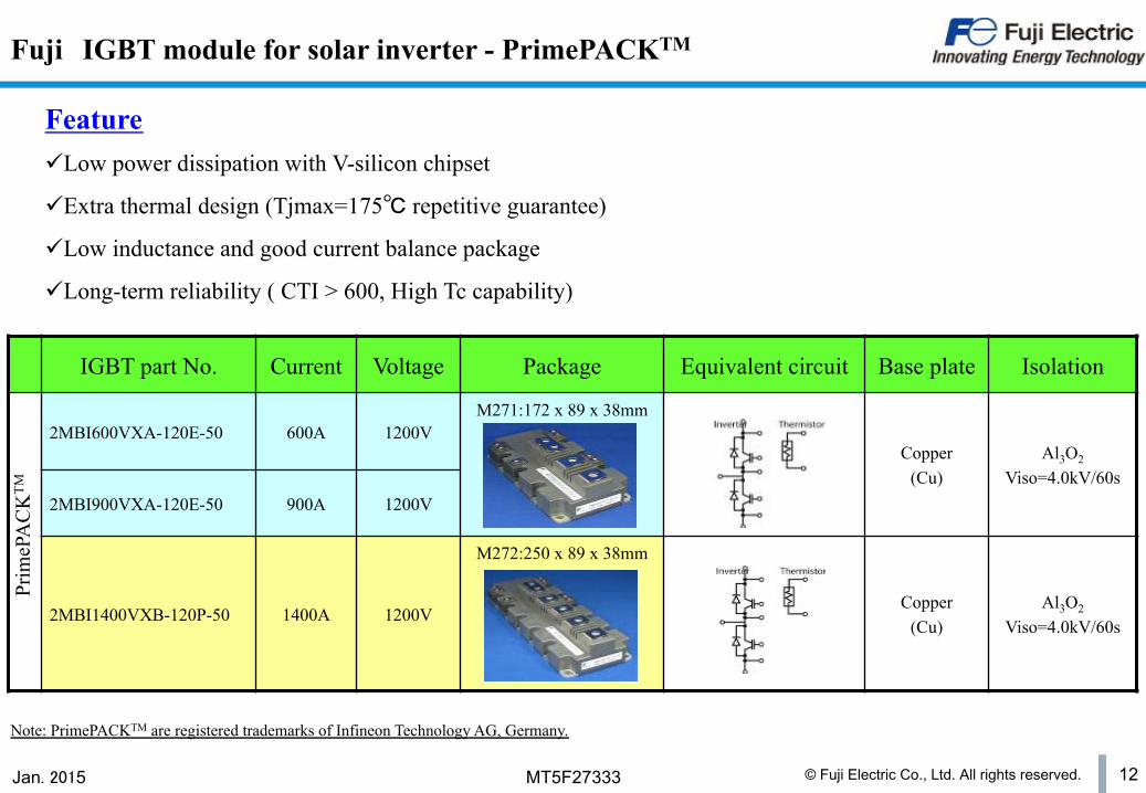
Fuji IGBT module for solar inverter - PrimePACKTM
IGBT part No. Current Voltage Package Equivalent circuit Base plate Isolation
2MBI600VXA-120E-50 600A 1200V M271:172 x 89 x 38mm
Copper (Cu)
Al3O2
Viso=4.0kV/60s 2MBI900VXA-120E-50 900A 1200V
2MBI1400VXB-120P-50 1400A 1200V
M272:250 x 89 x 38mm
Copper (Cu)
Al3O2
Viso=4.0kV/60s
Prim
ePA
CK
TM
Feature ü Low power dissipation with V-silicon chipset
ü Extra thermal design (Tjmax=175℃ repetitive guarantee)
ü Low inductance and good current balance package
ü Long-term reliability ( CTI > 600, High Tc capability)
Note: PrimePACKTM are registered trademarks of Infineon Technology AG, Germany.
© Fuji Electric Co., Ltd. All rights reserved. 13 Jan. 2015 MT5F27333
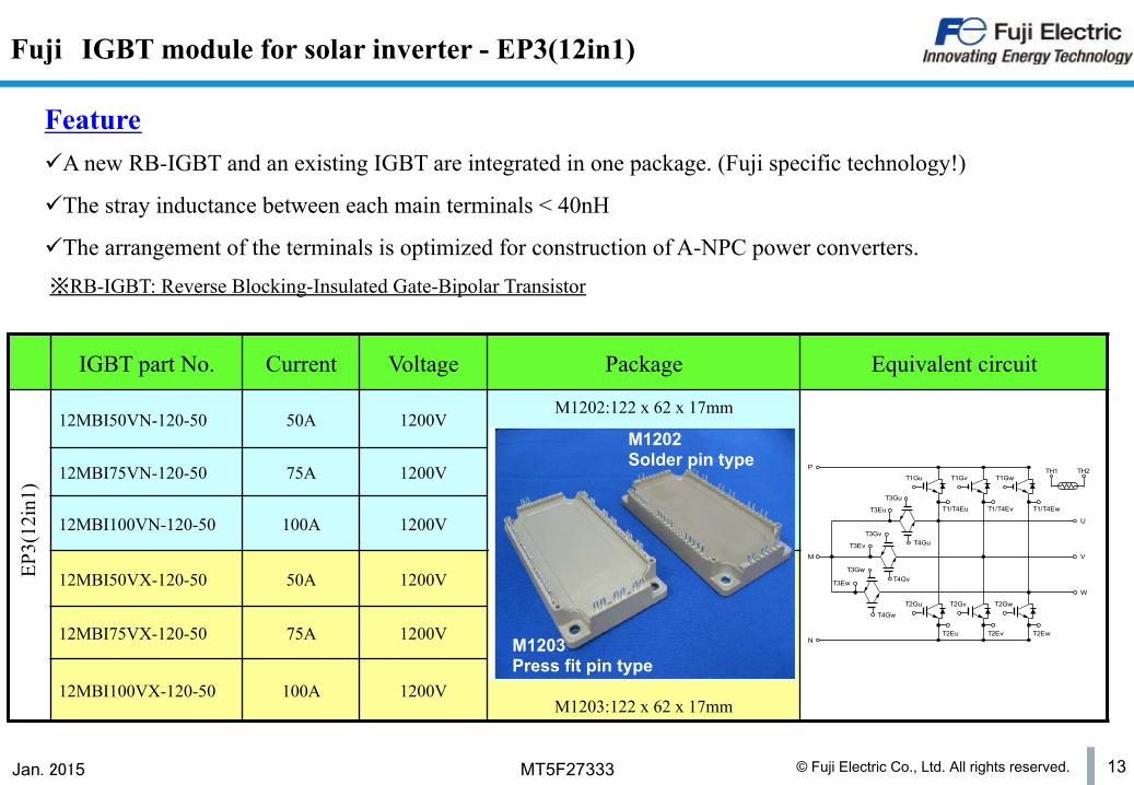
Fuji IGBT module for solar inverter - EP3(12in1)
IGBT part No. Current Voltage Package Equivalent circuit
12MBI50VN-120-50 50A 1200V M1202:122 x 62 x 17mm
12MBI75VN-120-50 75A 1200V
12MBI100VN-120-50 100A 1200V
12MBI50VX-120-50 50A 1200V
M1203:122 x 62 x 17mm
12MBI75VX-120-50 75A 1200V
12MBI100VX-120-50 100A 1200V
EP3(
12in
1)
Feature ü A new RB-IGBT and an existing IGBT are integrated in one package. (Fuji specific technology!)
ü The stray inductance between each main terminals < 40nH
ü The arrangement of the terminals is optimized for construction of A-NPC power converters. ※RB-IGBT: Reverse Blocking-Insulated Gate-Bipolar Transistor
T1Gu
T2Gu
T3Ew
P
M
N
U
V
W
T1Gv T1Gw
T2Gv T2Gw
T1/T4Eu T1/T4Ev T1/T4Ew
T2Eu T2Ev T2Ew
T3Eu
T3Ev
T3Gu
T3Gv
T3Gw
T4Gu
T4Gv
T4Gw
TH1 TH2
M1202 Solder pin type
M1203 Press fit pin type
© Fuji Electric Co., Ltd. All rights reserved. 14 Jan. 2015 MT5F27333
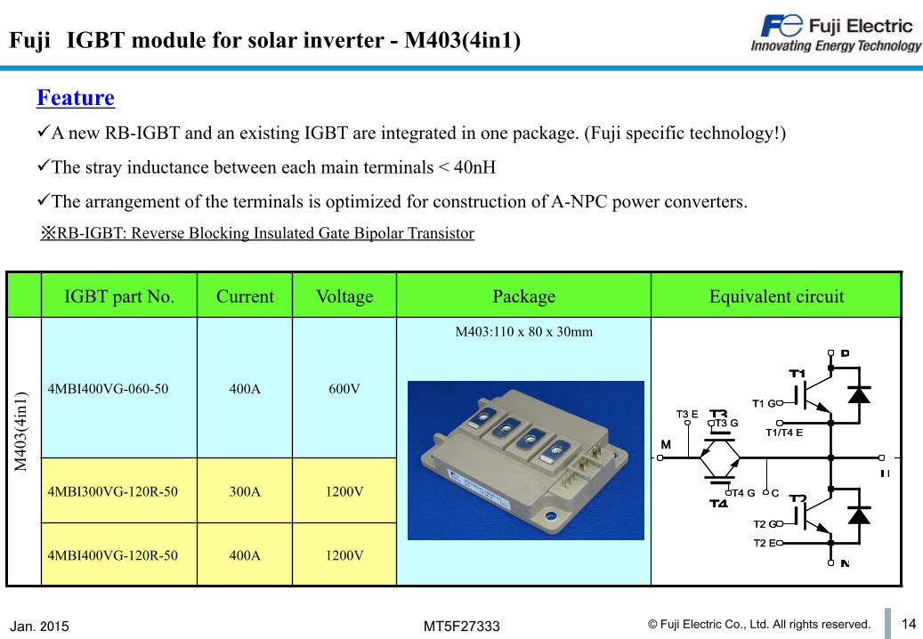
Fuji IGBT module for solar inverter - M403(4in1)
IGBT part No. Current Voltage Package Equivalent circuit
4MBI400VG-060-50 400A 600V
M403:110 x 80 x 30mm
4MBI300VG-120R-50 300A 1200V
4MBI400VG-120R-50 400A 1200V
M40
3(4i
n1)
Feature ü A new RB-IGBT and an existing IGBT are integrated in one package. (Fuji specific technology!)
ü The stray inductance between each main terminals < 40nH
ü The arrangement of the terminals is optimized for construction of A-NPC power converters.
T1
T2T4
T3
P
U
N
M
T1 G
T1/T4 E
T2 G
T2 E
T3 ET3 G
CT4 G
T1
T2T4
T3
P
U
N
M
T1 G
T1/T4 E
T2 G
T2 E
T3 ET3 G
CT4 G
MM
※RB-IGBT: Reverse Blocking Insulated Gate Bipolar Transistor
© Fuji Electric Co., Ltd. All rights reserved. 15 Jan. 2015 MT5F27333
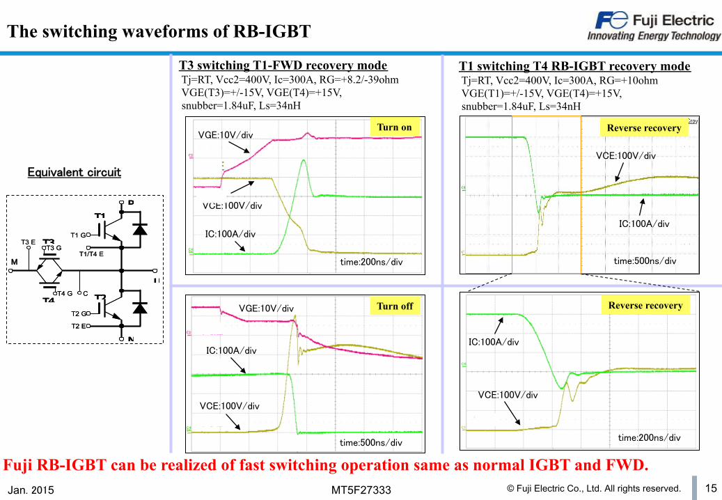
T3 switching T1-FWD recovery mode Tj=RT, Vcc2=400V, Ic=300A, RG=+8.2/-39ohm VGE(T3)=+/-15V, VGE(T4)=+15V, snubber=1.84uF, Ls=34nH
T1 switching T4 RB-IGBT recovery mode Tj=RT, Vcc2=400V, Ic=300A, RG=+10ohm VGE(T1)=+/-15V, VGE(T4)=+15V, snubber=1.84uF, Ls=34nH
Fuji RB-IGBT can be realized of fast switching operation same as normal IGBT and FWD.
The switching waveforms of RB-IGBT
T1
T2T4
T3
P
U
N
M
T1 G
T1/T4 E
T2 G
T2 E
T3 ET3 G
CT4 G
T1
T2T4
T3
P
U
N
M
T1 G
T1/T4 E
T2 G
T2 E
T3 ET3 G
CT4 G
MM
Equivalent circuit
Turn-off
VGE: 10V/div
VCE: 100V/div
IC: 100A/div
t: 500ns/div
VGE
VCE
IC
VCE:100V/div
IC:100A/div
VGE:10V/div
time:500ns/div
Turn off
Turn-on
VGE: 10V/div
VCE: 100V/div
IC: 100A/div
t: 200ns/div
VCE
IC
VGE
time:200ns/div
VGE:10V/div
VCE:100V/div
IC:100A/div
Turn on
Riverse-recovery
VCE: 100V/div
IC: 100A/div
t: 200ns/div
IC
VCEtime:200ns/div
time:500ns/div
VCE:100V/div
IC:100A/div
VCE:100V/div
IC:100A/div
Reverse recovery
Reverse recovery

© Fuji Electric Co., Ltd. All rights reserved. 16 Jan. 2015 MT5F27333
n Topology in solar inverter
n Fuji IGBT modules for solar inverter
n Fuji solution in Gate Driver Unit (GDU)
n Fuji 2 level topology solution
n Fuji 3 level topology solution - Stack
Table of contents
© Fuji Electric Co., Ltd. All rights reserved. 17 Jan. 2015 MT5F27333
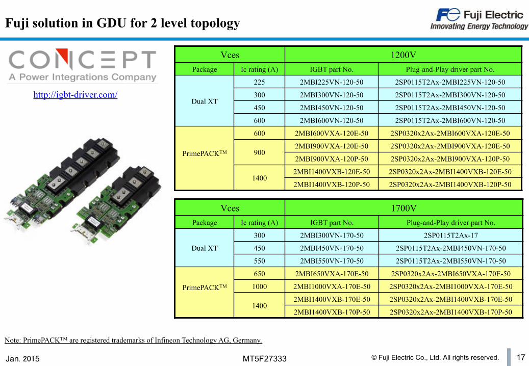
Fuji solution in GDU for 2 level topology
Vces 1200V Package Ic rating (A) IGBT part No. Plug-and-Play driver part No.
Dual XT
225 2MBI225VN-120-50 2SP0115T2Ax-2MBI225VN-120-50
300 2MBI300VN-120-50 2SP0115T2Ax-2MBI300VN-120-50
450 2MBI450VN-120-50 2SP0115T2Ax-2MBI450VN-120-50
600 2MBI600VN-120-50 2SP0115T2Ax-2MBI600VN-120-50
PrimePACKTM
600 2MBI600VXA-120E-50 2SP0320x2Ax-2MBI600VXA-120E-50
900 2MBI900VXA-120E-50 2SP0320x2Ax-2MBI900VXA-120E-50
2MBI900VXA-120P-50 2SP0320x2Ax-2MBI900VXA-120P-50
1400 2MBI1400VXB-120E-50 2SP0320x2Ax-2MBI1400VXB-120E-50
2MBI1400VXB-120P-50 2SP0320x2Ax-2MBI1400VXB-120P-50
Vces 1700V Package Ic rating (A) IGBT part No. Plug-and-Play driver part No.
Dual XT
300 2MBI300VN-170-50 2SP0115T2Ax-17
450 2MBI450VN-170-50 2SP0115T2Ax-2MBI450VN-170-50
550 2MBI550VN-170-50 2SP0115T2Ax-2MBI550VN-170-50
PrimePACKTM
650 2MBI650VXA-170E-50 2SP0320x2Ax-2MBI650VXA-170E-50
1000 2MBI1000VXA-170E-50 2SP0320x2Ax-2MBI1000VXA-170E-50
1400 2MBI1400VXB-170E-50 2SP0320x2Ax-2MBI1400VXB-170E-50
2MBI1400VXB-170P-50 2SP0320x2Ax-2MBI1400VXB-170P-50
Note: PrimePACKTM are registered trademarks of Infineon Technology AG, Germany.
http://igbt-driver.com/
© Fuji Electric Co., Ltd. All rights reserved. 18 Jan. 2015 MT5F27333
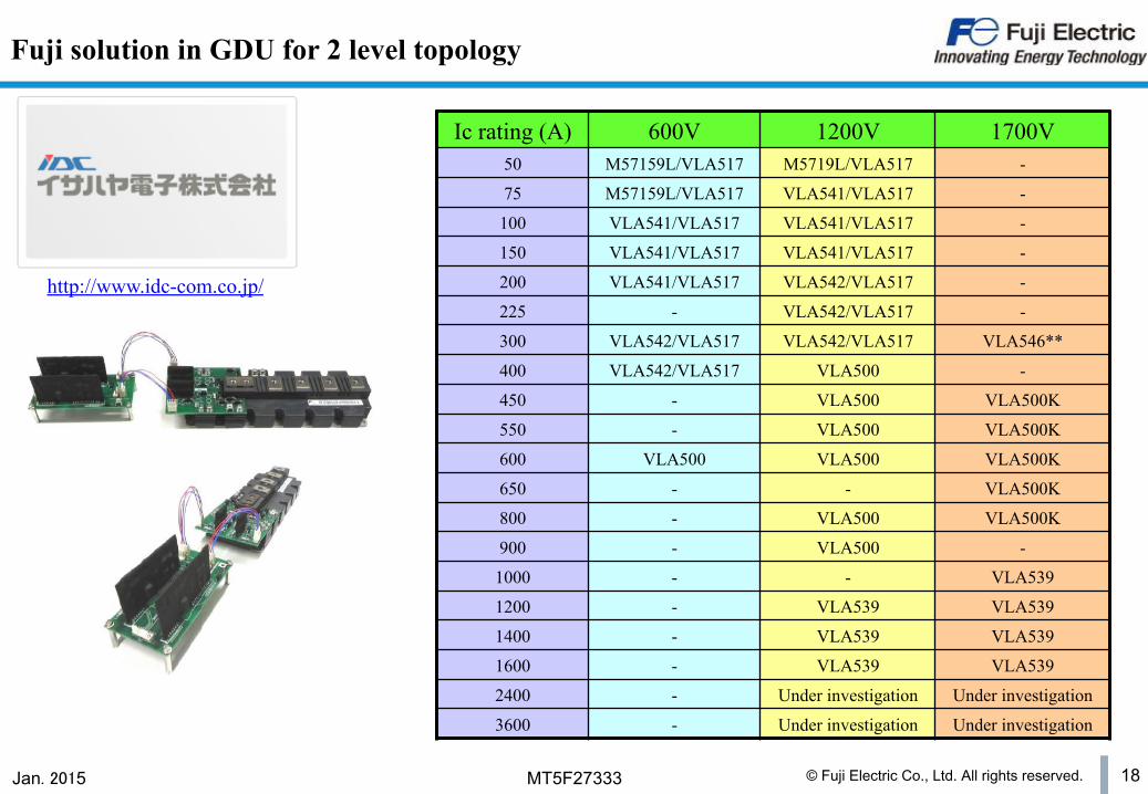
Fuji solution in GDU for 2 level topology
Ic rating (A) 600V 1200V 1700V 50 M57159L/VLA517 M5719L/VLA517 -
75 M57159L/VLA517 VLA541/VLA517 -
100 VLA541/VLA517 VLA541/VLA517 -
150 VLA541/VLA517 VLA541/VLA517 -
200 VLA541/VLA517 VLA542/VLA517 -
225 - VLA542/VLA517 -
300 VLA542/VLA517 VLA542/VLA517 VLA546**
400 VLA542/VLA517 VLA500 -
450 - VLA500 VLA500K
550 - VLA500 VLA500K
600 VLA500 VLA500 VLA500K
650 - - VLA500K
800 - VLA500 VLA500K
900 - VLA500 -
1000 - - VLA539
1200 - VLA539 VLA539
1400 - VLA539 VLA539
1600 - VLA539 VLA539
2400 - Under investigation Under investigation
3600 - Under investigation Under investigation
http://www.idc-com.co.jp/
© Fuji Electric Co., Ltd. All rights reserved. 19 Jan. 2015 MT5F27333
n Topology in solar inverter
n Fuji IGBT modules for solar inverter
n Fuji solution in Gate Driver Unit (GDU)
n Fuji 2 level topology solution
n Fuji 3 level topology solution - Stack
Table of contents
© Fuji Electric Co., Ltd. All rights reserved. 20 Jan. 2015 MT5F27333
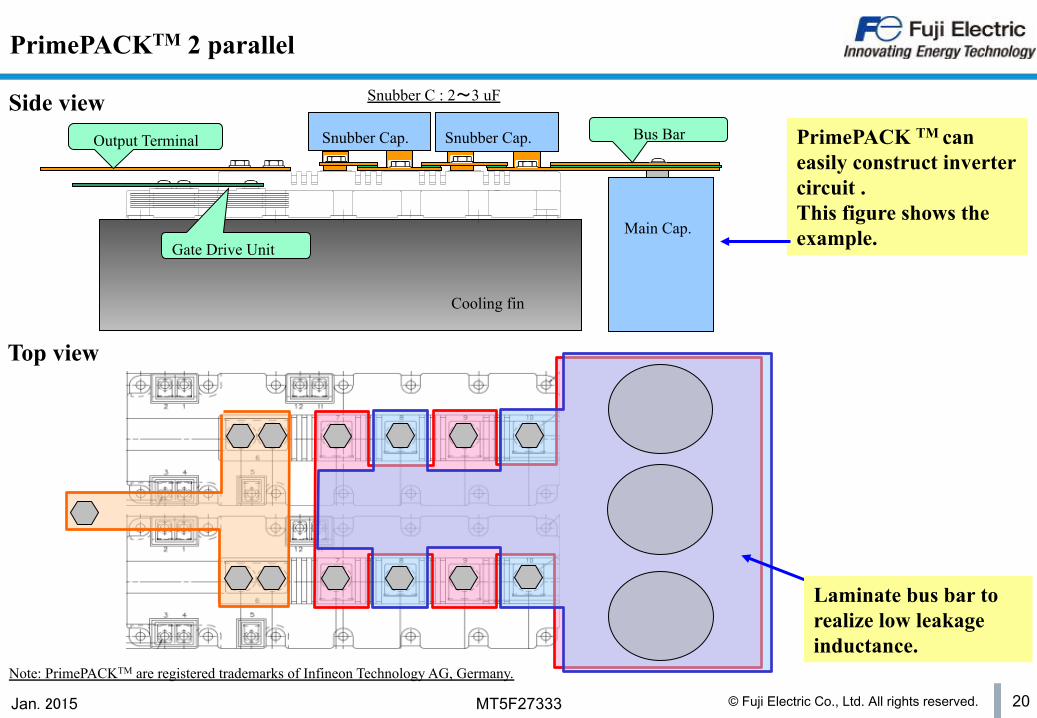
Gate Drive Unit
Snubber Cap. Snubber Cap.
Main Cap.
Bus Bar Output Terminal
Cooling fin
PrimePACKTM 2 parallel
Snubber C : 2~3 uF
Top view
Side view PrimePACK TM can easily construct inverter circuit . This figure shows the example.
Laminate bus bar to realize low leakage inductance.
Note: PrimePACKTM are registered trademarks of Infineon Technology AG, Germany.
© Fuji Electric Co., Ltd. All rights reserved. 21 Jan. 2015 MT5F27333
n Topology in solar inverter
n Fuji IGBT modules for solar inverter
n Fuji solution in Gate Driver Unit (GDU)
n Fuji 2 level topology solution
n Fuji 3 level topology solution - Stack
Table of contents

© Fuji Electric Co., Ltd. All rights reserved. 22 Jan. 2015 MT5F27333
Easy connected “3 level inverter” by 2in1 module and chopper module
2in1 Module
E2 E2 C1 C1
E2 E2 C1 C1
E2 E2 C1 C1
to Load
Cap.1
Cap.2 Cap.2
Cap.1
Chopper Module
Chopper Module
PrimePACKTM
© Fuji Electric Co., Ltd. All rights reserved. 23 Jan. 2015 MT5F27333
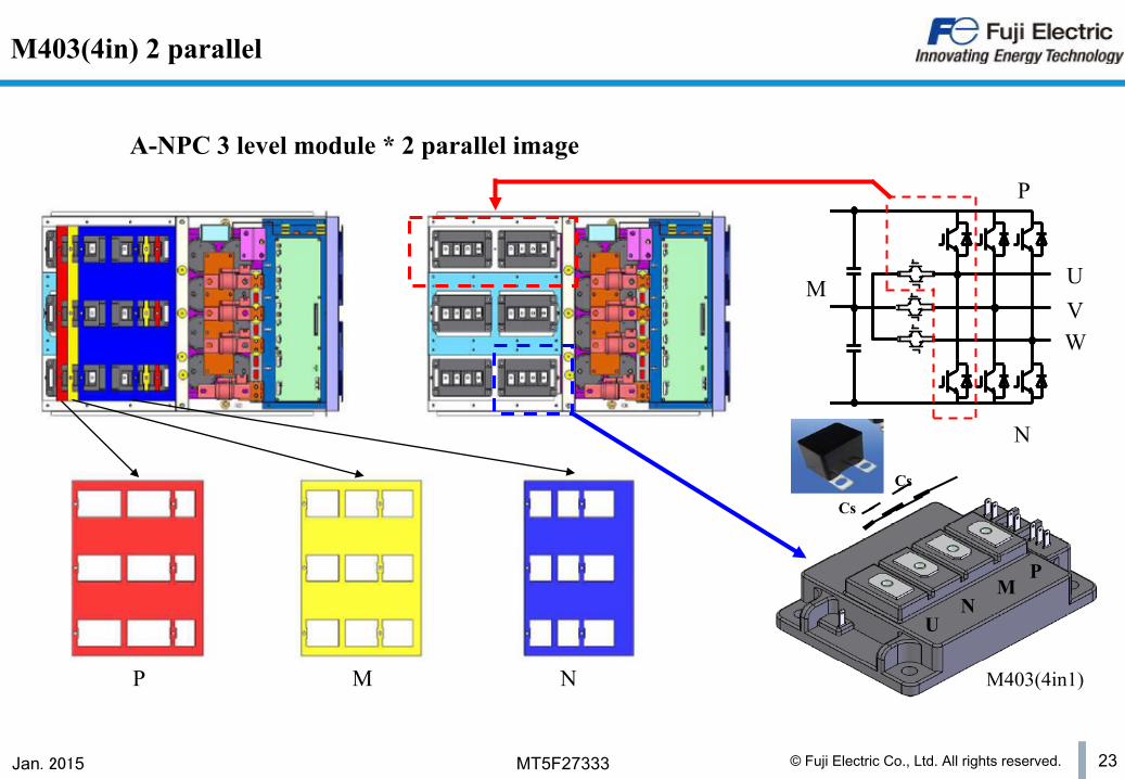
M403(4in) 2 parallel
P M N
A-NPC 3 level module * 2 parallel image
P
M
N
M403(4in1)
U V W
P M
N U
Cs
Cs

© Fuji Electric Co., Ltd. All rights reserved. 24 Jan. 2015 MT5F27333
M403(4in1) 2 parallel
P
M
N
M403(4in1)
U V W
P M
N U
Cs Cs
Assemble IGBT heat-sink and condenser Assemble insulation paper Assemble P busbar Assemble insulation paper Assemble M busbar Assemble insulation paper Assemble N busbar Assemble insulation paper Assemble output(U,V,W) Assemble screw
P M N U P M N U
© Fuji Electric Co., Ltd. All rights reserved. 25 Jan. 2015 MT5F27333 25
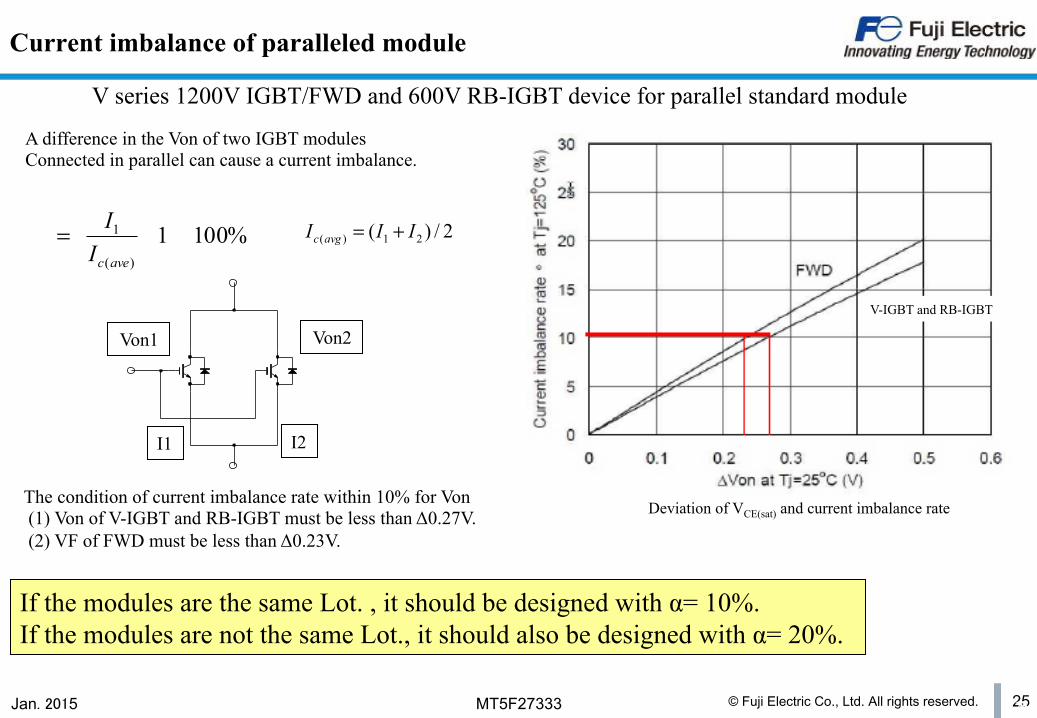
Deviation of VCE(sat) and current imbalance rate
V series 1200V IGBT/FWD and 600V RB-IGBT device for parallel standard module
Current imbalance of paralleled module
The condition of current imbalance rate within 10% for Von (1) Von of V-IGBT and RB-IGBT must be less than Δ0.27V. (2) VF of FWD must be less than Δ0.23V.
Von2 Von1
I2 I1
A difference in the Von of two IGBT modules Connected in parallel can cause a current imbalance.
If the modules are the same Lot. , it should be designed with α= 10%. If the modules are not the same Lot., it should also be designed with α= 20%.
%1001)(
1=avecII 2/)( 21)( III avgc +=
V-IGBT and RB-IGBT
© Fuji Electric Co., Ltd. All rights reserved. 26 Jan. 2015 MT5F27333 26
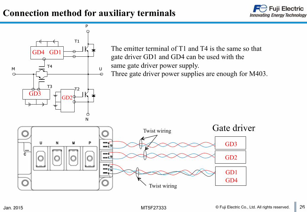
Connection method for auxiliary terminals
Gate driver
The emitter terminal of T1 and T4 is the same so that gate driver GD1 and GD4 can be used with the same gate driver power supply. Three gate driver power supplies are enough for M403.
T3
T4M U
P
T1
N
T2
GD1
GD2
GD4
GD3
GD3
GD2
GD1 GD4
Twist wiring
Twist wiring

© Fuji Electric Co., Ltd. All rights reserved. 27 Jan. 2015 MT5F27333
VCEP
Snubber capacitors
L: Main circuit wiring parasitic inductance Io: Collector current at IGBT turn-off VCEP: Snubber capacitor peak voltage Ed: DC supply voltage
( ) 2 2
Ed V Io L C
CEP S -
*
=
Vces Ic100A 0.2 μH 0.47μF300A 0.1μH 3.3μF450A 0.08 μH 4.7μF1000A 0.07μH 6.8μF1400A 0.06μH 12μF
Module ratingDC line inductance snubber capacitance
1200V/1700V