fujitsu storage eternus lt140 tape library user's guide
TRANSCRIPT

FUJITSU StorageETERNUS LT140 Tape Library
User's Guide -Installation & Operation-
P3AG-3722-02ENZ0

This page is intentionally left blank.

FUJITSU Storage ETERNUS LT140 Tape Library User’s Guide -Installation & Operation-
Copyright 2019 FUJITSU LIMITED P3AG-3722-02ENZ0
3
Preface
Fujitsu would like to thank you for purchasing our FUJITSU Storage ETERNUS LT140 Tape Library (hereinafterreferred to as LT140).The LT140 is designed to be connected to Fujitsu (PRIMEQUEST, PRIMERGY, Fujitsu M12/M10) or non-Fujitsuservers.This manual describes operational management and maintenance of the LT140.This manual is intended for use of the LT140 in regions other than Japan.Carefully read the information that is provided in this manual to ensure correct usage of the LT140.
Second EditionDecember 2019
LTO, Linear Tape-Open, and Ultrium are registered trademarks of Hewlett Packard Enterprise, L.P., IBMCorporation, and Quantum Corporation.All SPARC trademarks are used under license and are trademarks or registered trademarks of SPARCInternational, Inc. in the United States and other countries.Microsoft, Windows, and Internet Explorer are registered trademarks of Microsoft Corporation in the UnitedStates or certain other countries.Veritas and the Veritas Logo are trademarks or registered trademarks of Veritas Technologies LLC or itsaffiliates in the U.S. and other countries.Dell EMC and NetWorker are registered trademarks or trademarks of Dell Inc. or its subsidiaries.NetVault is a trademark of Quest Software Inc. The Quest Software logo and products are registeredtrademarks of Quest Software Inc. in the United States and other countries.The company names, product names and service names mentioned in this document are registeredtrademarks or trademarks of their respective companies.
Microsoft product screen shot(s) reprinted with permission from Microsoft Corporation.

About this Manual
Organization
This manual is composed of the following seven chapters and an appendix:
● Chapter 1 Preparation
This chapter describes the necessary preparation for installation of the LT140.
● Chapter 2 Components
This chapter describes hardware module configurations for the LT140.
● Chapter 3 Basic Operation
This chapter describes basic operations that are required every day.
● Chapter 4 Default Setting
This chapter explains how to satisfy the minimum setup requirements for installation.
● Chapter 5 Monitoring the LT140 Status
This chapter explains how to confirm the tape library status and other items.
● Chapter 6 Function Expansion Option
This chapter explains product options that can be added as required after system operation starts.
● Chapter 7 Troubleshooting
This chapter provides troubleshooting.
The following content is described as an appendix:• Tape Cartridge and Barcode Label Specifications
FUJITSU Storage ETERNUS LT140 Tape Library User’s Guide -Installation & Operation-
Copyright 2019 FUJITSU LIMITED P3AG-3722-02ENZ0
4

About this Manual
Warning Notations
Warning signs are shown throughout this manual in order to prevent injury to the user and/or materialdamage. These signs are composed of a symbol and a message describing the recommended level of caution.The following section explains the symbols, their levels of caution, and their meanings as used in this manual.
The following symbols are used to indicate the type of warnings or cautions being described.
WARNINGThis symbol indicates the possibility of serious or fatal injury if the LT140 is not used properly.
CAUTIONThis symbol indicates the possibility of minor or moderate personal injury, as well as damage to the LT140 and/or to other users and their property, if the LT140 is not used properly.
This symbol indicates IMPORTANT information for the user to note when using the LT140.
Electric ShockThe triangle emphasizes the urgency of the WARNING and CAUTION contents.
Inside the triangle and above it are details concerning the symbol (e.g. Electrical Shock).
No DisassemblyThe barred "Do Not..." circle warns against certain actions. The action which must
be avoided is both illustrated inside the barred circle and written above it (e.g. No Disassembly).
UnplugThe black "Must Do..." disk indicates actions that must be taken. The required
action is both illustrated inside the black disk and written above it (e.g. Unplug).
FUJITSU Storage ETERNUS LT140 Tape Library User’s Guide -Installation & Operation-
Copyright 2019 FUJITSU LIMITED P3AG-3722-02ENZ0
5

About this Manual
How Warnings are Presented in this Manual
A message is written beside the symbol indicating the caution level. This message is marked with a verticalribbon in the left margin, to distinguish this warning from ordinary descriptions.An example is shown here.
Naming Conventions
Symbols Used in This Manual
The following symbols are used throughout this manual:
Abbreviations Used in This Manual
• "LT140" refers to the FUJITSU Storage ETERNUS LT140 Tape Library.• Trademark symbols such as ™ and ® are omitted in this manual.
Warning Level Indicator
Warning Type Indicator
Warning Details
To avoid damaging the LT140, pay attention to the following points when cleaning the LT140:
- Make sure to disconnect the power when cleaning.- Be careful that no liquid seeps into the LT140 when using cleaners, etc.- Do not use alcohol or other solvents to clean the LT140.
Warning Layout Ribbon
Example Warning
This symbol alerts operators to particularly important information. Be sure to read this information.
Functions and know how which can be useful when setting up or operating the LT140.
FUJITSU Storage ETERNUS LT140 Tape Library User’s Guide -Installation & Operation-
Copyright 2019 FUJITSU LIMITED P3AG-3722-02ENZ0
6

FUJITSU Storage ETERNUS LT140 Tape Library User’s Guide -Installation & Operation-
Copyright 2019 FUJITSU LIMITED P3AG-3722-02ENZ0
7
Warning Labels and Manufacturer's Labels
Caution labels, manufacturer's labels, and a device ID label are found in various places of the LT140.Never remove these labels from the equipment or allow them to become dirty.
Note that the labels shown below are examples. The LT140 also has other labels that include importantinformation.
■ Prohibition
Do not put anything on the LT140. In addition, putting the LT140 like an above picture is forbidden.
■ Warning for making the LT140 transferred
More than two people are required to carry the LT140.
■ Notes on the weight
The LT140's weight is range of 22kg to 36kg.A breakdown of the weight is as follows:
Base Module: 22kg (robot x1, PSU x 2, tape drive x 0)Expansion Module: 14kg (robot x 0, tape drive x 0)
A single tape drive is approximately 2kg and a single power supply is approximately 1kg.
Table of Contents
Chapter 1 Preparation 15
1.1 Host Connection ................................................................................................................ 15
1.2 Connection to LAN for Operation Management ................................................................ 15
Chapter 2 Components 16
2.1 Module ............................................................................................................................. 172.1.1 Base Module Front View ................................................................................................................................ 172.1.2 Base Module Rear View ................................................................................................................................. 192.1.3 Expansion Module Front View ....................................................................................................................... 202.1.4 Expansion Module Rear View ......................................................................................................................... 21
2.2 Operator Panel .................................................................................................................. 22
2.3 Magazine .......................................................................................................................... 24
2.4 Mailslot ............................................................................................................................. 25
2.5 Drive Module .................................................................................................................... 262.5.1 Rear Side of the Drive Module ....................................................................................................................... 26
2.6 Robotic Assembly .............................................................................................................. 27
2.7 Library Controller .............................................................................................................. 28
2.8 Tape Drive Unit ................................................................................................................. 29
2.9 Power Supply Unit (PSU) ................................................................................................... 30
Chapter 3 Basic Operation 31
3.1 Powering On/Off ................................................................................................................ 313.1.1 Points to Note when Turning On or Turning Off the LT140 ............................................................................. 333.1.2 Turning on the Server .................................................................................................................................... 33
3.2 Operator Panel Operation ................................................................................................. 343.2.1 Logging into the Library ................................................................................................................................ 343.2.2 Using the Operator Panel Home Screen ......................................................................................................... 36
3.3 Operating the Library ........................................................................................................ 383.3.1 Moving Media ................................................................................................................................................ 383.3.2 Moving the Media from the Tape Drive to a Slot ............................................................................................ 383.3.3 Rescanning the Cartridge Inventory ............................................................................................................... 38
FUJITSU Storage ETERNUS LT140 Tape Library User’s Guide -Installation & Operation-
Copyright 2019 FUJITSU LIMITED P3AG-3722-02ENZ0
8

Table of Contents
3.4 Configuring the Library ..................................................................................................... 393.4.1 Using Initial System Setup ............................................................................................................................. 393.4.2 Setting the Date and Time ............................................................................................................................. 393.4.3 Tape Drive Power Operation .......................................................................................................................... 40
3.5 Loading and Ejecting Tape Cartridges ............................................................................... 413.5.1 Unlocking the Magazine or Mailslot .............................................................................................................. 413.5.2 Pulling Out a Magazine or Mailslot ................................................................................................................ 453.5.3 Notes on Installing Magazines ...................................................................................................................... 463.5.4 Inserting Tape Cartridges ............................................................................................................................... 49
3.6 Cleaning Tape Drives ......................................................................................................... 513.6.1 Auto-Cleaning with the Backup Software ....................................................................................................... 513.6.2 Cleaning Tape Drives Manually ...................................................................................................................... 52
Chapter 4 Default Setting 53
4.1 Login ................................................................................................................................ 53
4.2 Using the Initial System Setup .......................................................................................... 56
4.3 Saving and Restoring the Library Configuration Setting File ............................................. 59
Chapter 5 Monitoring the LT140 Status 60
5.1 Operator Panel .................................................................................................................. 60
5.2 Remote Panel ................................................................................................................... 605.2.1 Top Banner Elements .................................................................................................................................... 615.2.2 Left Pane Elements ........................................................................................................................................ 625.2.3 Center Pane Elements ................................................................................................................................... 63
5.3 Configuring Event Notification Parameters ....................................................................... 64
5.4 Fault Monitoring (SNMP Report Function) ........................................................................ 66
Chapter 6 Function Expansion Option 67
6.1 Expandable Components .................................................................................................. 67
6.2 License Partitioning Option (Logical Library Function) ..................................................... 696.2.1 Function Overview ......................................................................................................................................... 706.2.2 Hardware Configuration ................................................................................................................................ 706.2.3 Designing Logical Libraries ............................................................................................................................ 736.2.4 Configuring Logical Libraries ......................................................................................................................... 74
6.3 Key Management Function Option ................................................................................... 846.3.1 Overview ........................................................................................................................................................ 846.3.2 Features of the Key Management Function Option ........................................................................................ 85
FUJITSU Storage ETERNUS LT140 Tape Library User’s Guide -Installation & Operation-
Copyright 2019 FUJITSU LIMITED P3AG-3722-02ENZ0
9

Table of Contents
6.3.3 Types of Key ................................................................................................................................................... 866.3.4 Operational Examples ................................................................................................................................... 876.3.5 Connectivity with Backup Software ................................................................................................................ 90
Chapter 7 Troubleshooting 91
7.1 Fibre Channel Connection Problems ................................................................................. 91
7.2 Detection Problems after Installing a SAS Drive ................................................................ 92
7.3 Operation Problems .......................................................................................................... 947.3.1 Power Problems ............................................................................................................................................. 947.3.2 Failure/Attention Indications Displayed on the Operator Panel ..................................................................... 957.3.3 Tape Movement Problems ............................................................................................................................. 957.3.4 Media Problems ............................................................................................................................................. 967.3.5 Attention LED is Lit ........................................................................................................................................ 977.3.6 Turning Off the Attention LED ........................................................................................................................ 987.3.7 Inventory Problems ....................................................................................................................................... 987.3.8 Remote Panel Network Connection Issues ..................................................................................................... 997.3.9 Cleaning Problems ......................................................................................................................................... 99
7.4 Performance Problems .................................................................................................... 1007.4.1 Average File Size .......................................................................................................................................... 1007.4.2 File Storage System ..................................................................................................................................... 1007.4.3 Connection from the Backup/Archive Host Server to the Disk Storage System ............................................. 1017.4.4 Backup/Archive Server ................................................................................................................................. 1017.4.5 Backup/Archive Software and Method ......................................................................................................... 1017.4.6 Connection from the Archive/Backup Host Server to the Library .................................................................. 1017.4.7 Media .......................................................................................................................................................... 102
7.5 Checking Event Information ............................................................................................ 102
7.6 Unlocking the Magazine ................................................................................................. 1037.6.1 Using the Magazine Open Button ................................................................................................................ 1037.6.2 Using the Remote Panel .............................................................................................................................. 1037.6.3 Using the Manual Release ........................................................................................................................... 105
7.7 Unloading a Stuck Tape .................................................................................................. 106
7.8 Identifying a Failed Component ...................................................................................... 106
7.9 Returning the Robotic Assembly to the Base Module ...................................................... 107
7.10 Running Library Tests ..................................................................................................... 107
7.11 Assistance during Maintenance ...................................................................................... 108
7.12 User Operations after Replacing Maintenance Parts ....................................................... 108
FUJITSU Storage ETERNUS LT140 Tape Library User’s Guide -Installation & Operation-
Copyright 2019 FUJITSU LIMITED P3AG-3722-02ENZ0
10

Table of Contents
Appendix A Tape Cartridge and Barcode Label Specifications 109
A.1 Ultrium Tape Cartridge..................................................................................................... 109A.1.1 Tape Cartridge Specifications....................................................................................................................... 109A.1.2 Tape Drive Compatibility with Tape Cartridges............................................................................................. 111A.1.3 Notes Regarding the Use of Tape Cartridges................................................................................................ 112A.1.4 Handling Tape Cartridges ............................................................................................................................ 113
A.2 Barcode Labels ................................................................................................................ 118A.2.1 Barcode Label Specifications ....................................................................................................................... 118A.2.2 Notes on Affixing a Barcode Label............................................................................................................... 120
FUJITSU Storage ETERNUS LT140 Tape Library User’s Guide -Installation & Operation-
Copyright 2019 FUJITSU LIMITED P3AG-3722-02ENZ0
11
List of Figures
Figure 2.1 Base Module front view............................................................................................................................... 17Figure 2.2 Base Module rear view ................................................................................................................................ 19Figure 2.3 Expansion Module front view ...................................................................................................................... 20Figure 2.4 Expansion Module rear view ....................................................................................................................... 21Figure 2.5 Status LEDs.................................................................................................................................................. 22Figure 2.6 Magazine mechanism ................................................................................................................................. 24Figure 2.7 Mailslot mounting locations (base module)................................................................................................ 25Figure 2.8 Mailslot mechanism .................................................................................................................................... 25Figure 2.9 Rear view of LTO-6 HH SAS (Product ID: LT14ASKE, LT14ASKL),
Rear view of LTO-7 HH SAS (Product ID: LT14ASME, LT14ASML),Rear view of LTO-8 HH SAS (Product ID: LT14ASNE, LT14ASNL) ................................................................... 26
Figure 2.10 Rear view of LTO-6 HH FC (Product ID: LT14AFKE, LT14AFKL), Rear view of LTO-7 HH FC (Product ID: LT14AFME, LT14AFML), Rear view of LTO-8 HH FC (Product ID: LT14AFNE, LT14AFNL) .................................................................... 27
Figure 2.11 Robotic Assembly ........................................................................................................................................ 27Figure 2.12 Library controller (Base Module/Expansion Module)................................................................................... 28Figure 2.13 Tape drive unit and drive power board ........................................................................................................ 29Figure 2.14 Power supply unit (PSU).............................................................................................................................. 30Figure 3.1 Power switch ............................................................................................................................................... 31Figure 3.2 Window selecting the robotic assembly parked position ............................................................................. 32Figure 3.3 Login screen................................................................................................................................................ 34Figure 3.4 Operator panel Home screen....................................................................................................................... 36Figure 3.5 Selecting Open Magazines/Mailslots ........................................................................................................... 42Figure 3.6 Open Magazines/Mailslots screen ............................................................................................................... 42Figure 3.7 Open Magazines/Mailslots notification screen ............................................................................................ 43Figure 3.8 Magazine/Mailslot....................................................................................................................................... 44Figure 3.9 Direction to pull out the magazine or Mailslot ............................................................................................ 45Figure 3.10 Inserting magazines (correct guide position) .............................................................................................. 47Figure 3.11 Inserting magazines (incorrect guide position) ........................................................................................... 48Figure 3.12 Tape cartridge insertion direction................................................................................................................ 49Figure 3.13 Clean Drive screen ....................................................................................................................................... 52Figure 4.1 Screensaver screen ...................................................................................................................................... 53Figure 4.2 Select User selection screen......................................................................................................................... 54Figure 4.3 Enter PIN screen .......................................................................................................................................... 54Figure 4.4 Enter PIN confirmation screen..................................................................................................................... 54Figure 4.5 Home screen ............................................................................................................................................... 55Figure 4.6 Configuration selection screen .................................................................................................................... 55Figure 4.7 Initial Configuration screen ......................................................................................................................... 56Figure 4.8 Network Configuration screen ..................................................................................................................... 57Figure 4.9 Date / Time Configuration screen ................................................................................................................ 57Figure 4.10 Administrator PIN input screen.................................................................................................................... 58Figure 4.11 Administrator PIN input confirmation screen .............................................................................................. 58Figure 4.12 Initial Configuration completion screen....................................................................................................... 58Figure 5.1 Home screen of remote panel ..................................................................................................................... 61Figure 5.2 SMTP screen ................................................................................................................................................ 64Figure 5.3 SNMP function............................................................................................................................................. 66Figure 6.1 Direct connection (FC-AL connection, a multiple server connection, a shared library,
and tape drives that are not shared) ........................................................................................................... 69
FUJITSU Storage ETERNUS LT140 Tape Library User’s Guide -Installation & Operation-
Copyright 2019 FUJITSU LIMITED P3AG-3722-02ENZ0
12
List of Figures
Figure 6.2 Example for partitioning cells: In the case that the Basic Partition Wizard is used ...................................... 71Figure 6.3 Example for partitioning cells: In the case that the Expert Partition Wizard is used .................................... 72Figure 6.4 Key Management Function Option .............................................................................................................. 84Figure 6.5 Concept of automatic encryption key generation ........................................................................................ 87Figure 6.6 Sharing data cartridges using a master key................................................................................................. 87Figure 6.7 External storage of data cartridges.............................................................................................................. 88Figure 6.8 Encryption key setting for each logical library ............................................................................................. 89Figure 6.9 Interoperation among LT-series models ...................................................................................................... 90Figure 7.1 Home screen of remote panel ................................................................................................................... 104Figure 7.2 Open Magazine screen .............................................................................................................................. 104Figure 7.3 How to use the Manual Release ................................................................................................................ 105Figure A.1 Latched state of the leader pin (the leader pin is latched)........................................................................ 115Figure A.2 Latched state of the leader pin (the leader pin has been removed).......................................................... 115Figure A.3 Fit state of clips (clips fit correctly) ............................................................................................................ 116Figure A.4 Fit state of clips (clips do not fit correctly (the leader pin is misaligned)) ................................................. 116Figure A.5 Character string on barcode label.............................................................................................................. 118Figure A.6 Barcode label affixing location.................................................................................................................. 120
FUJITSU Storage ETERNUS LT140 Tape Library User’s Guide -Installation & Operation-
Copyright 2019 FUJITSU LIMITED P3AG-3722-02ENZ0
13

FUJITSU Storage ETERNUS LT140 Tape Library User’s Guide -Installation & Operation-
Copyright 2019 FUJITSU LIMITED P3AG-3722-02ENZ0
14
List of Tables
Table 2.1 Name of each component (front side of the Base Module) ......................................................................... 17Table 2.2 Name of each component (rear side of the Base Module)........................................................................... 19Table 2.3 Name of each component (front side of the Expansion Module) ................................................................ 20Table 2.4 Name of each component (rear side of the Expansion Module).................................................................. 21Table 2.5 Meanings of each LED (LT140 status) ......................................................................................................... 22Table 2.6 Details of the magazine open buttons ........................................................................................................ 23Table 2.7 Meanings of each LED (library controller) ................................................................................................... 29Table 2.8 Meanings of each LED (power supply unit) ................................................................................................. 30Table 3.1 Details of the magazine open buttons ........................................................................................................ 44Table 5.1 Top banner elements .................................................................................................................................. 61Table 5.2 Left pane elements ..................................................................................................................................... 62Table 5.3 Center pane elements ................................................................................................................................. 63Table 6.1 Component Configurations (Base Module / Expansion Module).................................................................. 67Table 6.2 An example of a layout for logical libraries ................................................................................................. 73Table A.1 Tape cartridge specifications (1/2) ............................................................................................................ 109Table A.2 Tape cartridge specifications (2/2) ............................................................................................................ 110Table A.3 Tape drive compatibility with data cartridges............................................................................................ 111Table A.4 Tape cartridge storage environment ......................................................................................................... 113Table A.5 Tape cartridge transport environment....................................................................................................... 113Table A.6 Characters that can be used on barcode labels.......................................................................................... 119Table A.7 Cartridge type and specified string ............................................................................................................ 119
Chapter 1
Preparation
This chapter describes the necessary preparation for installation of the LT140.This section describes the necessary information, and the devices and cables that should be prepared beforeyou connect the LT140 to a Storage Area Network (SAN) and a LAN for operation management.
1.1 Host Connection
A SAN is a dedicated network for connecting a server (host) to an LT140. A Fibre Channel (FC)/Serial AttachedSCSI (SAS) interface can be used for the host interface. The connection destination may be the server or theswitch depending on which connection configuration is used.The host interface cables that are used for connecting the LT140 to a SAN must be obtained separately. Whena switch is used to connect the LT260 to the server, the appropriate switch for the type of host interface that isto be connected must also be prepared separately.
1.2 Connection to LAN for Operation Management
The LT140 must be connected to the LAN for operation management during operation management andsystem maintenance.
Acquire an IP address for the LT140 beforehand so that a LAN environment can be set up during installation.In addition, network devices and other items must be prepared so that the LT140 can be connected to a LANfor operation management.
FUJITSU Storage ETERNUS LT140 Tape Library User’s Guide -Installation & Operation-
Copyright 2019 FUJITSU LIMITED P3AG-3722-02ENZ0
15
Chapter 2
Components
This chapter describes the hardware component configurations for the LT140.All components such as operator panels, magazines, Mailslots, drive modules, robots, library controllers, tapedrives, and power supply units are installed in modules.
FUJITSU Storage ETERNUS LT140 Tape Library User’s Guide -Installation & Operation-
Copyright 2019 FUJITSU LIMITED P3AG-3722-02ENZ0
16
Chapter 2 Components 2.1 Module
2.1 Module
Two types of Modules are available for the LT140: a Base Module and an Expansion Module.Major components are installed in each module.
The external view of the LT140 is shown blow.
2.1.1 Base Module Front View
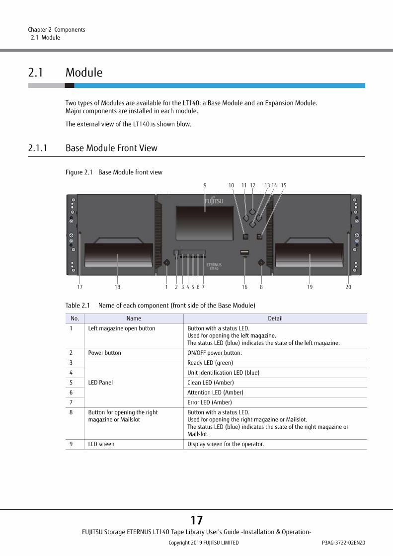
Figure 2.1 Base Module front view
Table 2.1 Name of each component (front side of the Base Module)
No. Name Detail
1 Left magazine open button Button with a status LED.Used for opening the left magazine.The status LED (blue) indicates the state of the left magazine.
2 Power button ON/OFF power button.
3
LED Panel
Ready LED (green)
4 Unit Identification LED (blue)
5 Clean LED (Amber)
6 Attention LED (Amber)
7 Error LED (Amber)
8 Button for opening the right magazine or Mailslot
Button with a status LED.Used for opening the right magazine or Mailslot.The status LED (blue) indicates the state of the right magazine or Mailslot.
9 LCD screen Display screen for the operator.
1 2 3 4 5 6 7
9 10 11 12 13 14 15
16 19 2081817
FUJITSU Storage ETERNUS LT140 Tape Library User’s Guide -Installation & Operation-
Copyright 2019 FUJITSU LIMITED P3AG-3722-02ENZ0
17
Chapter 2 Components 2.1 Module
■ Selecting a Menu
Menus can be selected using the operation buttons. Move the cursor over the target menu using the Up,Down, Left, and Right buttons and then press the Enter button to confirm. To cancel the selection or return tothe previous screen, select the target menu or press the Back/Return button.
■ Selecting from the Drop-down List
Use the Up and Down buttons to select from the drop-down list. Move the cursor over the target menu andpress the Enter button to display the pull down box. After that, move the cursor over the target item using theUp and Down buttons and then press the Enter button.
■ Entering Values
Values can be entered using the operation buttons (Up, Down, Left, and Right). Move the cursor over thetarget menu and press the Enter button to display the combo box. After that, select a value for each digitusing the Up and Down buttons. To move to another digit, use the Left and Right button. After entering thevalues, press the Enter button.
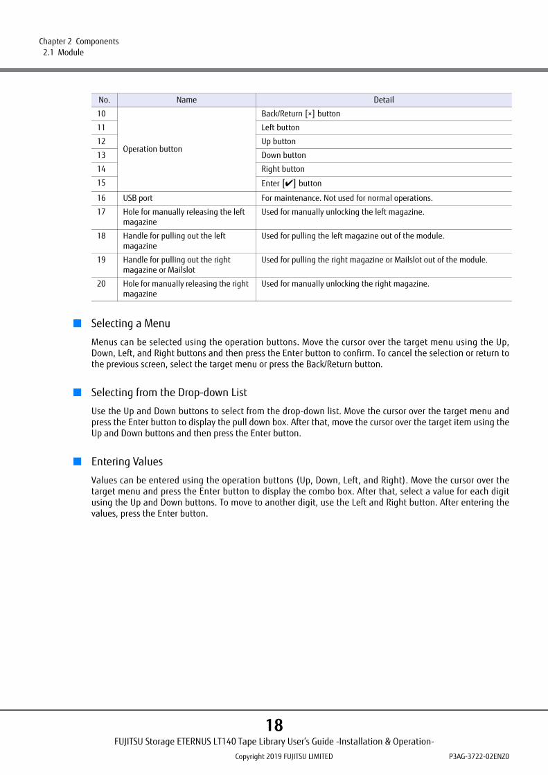
10
Operation button
Back/Return [×] button
11 Left button
12 Up button
13 Down button
14 Right button
15 Enter [✔] button
16 USB port For maintenance. Not used for normal operations.
17 Hole for manually releasing the left magazine
Used for manually unlocking the left magazine.
18 Handle for pulling out the left magazine
Used for pulling the left magazine out of the module.
19 Handle for pulling out the right magazine or Mailslot
Used for pulling the right magazine or Mailslot out of the module.
20 Hole for manually releasing the right magazine
Used for manually unlocking the right magazine.
No. Name Detail
FUJITSU Storage ETERNUS LT140 Tape Library User’s Guide -Installation & Operation-
Copyright 2019 FUJITSU LIMITED P3AG-3722-02ENZ0
18

Chapter 2 Components 2.1 Module
2.1.2 Base Module Rear View
Figure 2.2 Base Module rear view
Table 2.2 Name of each component (rear side of the Base Module)
No. Name Detail
1 Power Supplies Base modules are installed with a single PSU as standard. A second PSU for redundancy is optional.
2 Half-Height Tape Drive Bays A maximum of three half-height drives can be installed.
3 Library Controller(for Base Modules)
—
4 Module Alignment Mechanism The mechanism for locating modules when connected.
1 2
4
3
FUJITSU Storage ETERNUS LT140 Tape Library User’s Guide -Installation & Operation-
Copyright 2019 FUJITSU LIMITED P3AG-3722-02ENZ0
19

Chapter 2 Components 2.1 Module
2.1.3 Expansion Module Front View
Figure 2.3 Expansion Module front view
Table 2.3 Name of each component (front side of the Expansion Module)
No. Component Detail
1 Left magazine open button Button with a status LED.Used for opening the left magazine.The status LED (blue) indicates the state of the left magazine.
2 Button for opening the right magazine or Mailslot
Button with a status LED.Used for opening the right magazine or Mailslot.The status LED (blue) indicates the state of the right magazine or Mailslot.
3 Transparent window —
4 Hole for manually releasing the left magazine
Used for manually unlocking the left magazine.
5 Handle for pulling out the left magazine
Used for pulling the left magazine out of the module.
6 Handle for pulling out the right magazine or Mailslot
Used for pulling the right magazine or Mailslot out of the module.
7 Hole for manually releasing the right magazine
Used for manually unlocking the right magazine.
4 15
3
72 6
FUJITSU Storage ETERNUS LT140 Tape Library User’s Guide -Installation & Operation-
Copyright 2019 FUJITSU LIMITED P3AG-3722-02ENZ0
20

Chapter 2 Components 2.1 Module
2.1.4 Expansion Module Rear View
Figure 2.4 Expansion Module rear view
Table 2.4 Name of each component (rear side of the Expansion Module)
No. Name Detail
1 Power Supplies Optional PSU are available for Expansion Modules.
2 Half-Height Tape Drive Bays A maximum of three half-height drives can be installed.
3 Library Controller(for Expansion Modules)
—
4 Module Alignment Mechanism The mechanism for locating modules when connected.
1 2 3
4
FUJITSU Storage ETERNUS LT140 Tape Library User’s Guide -Installation & Operation-
Copyright 2019 FUJITSU LIMITED P3AG-3722-02ENZ0
21

Chapter 2 Components 2.2 Operator Panel
2.2 Operator Panel
The operator panel consists of a power button, display, six operation buttons, left and right magazine openbuttons, and five LEDs. The operator panel allows the user to use functions such as monitoring, configuring,and operating the library. All operator panel operations are performed using the buttons. LEDs indicate thelibrary status based on the lighting state. The magazine open buttons are used to operate the magazines orindicate the status of the magazines based on the lighting state of an LED.
■ Status LEDs
Status LEDs are mounted on the front panel of the Base Module. Use these LEDs to check the status of theLT140.
Figure 2.5 Status LEDs
The LEDs turn on or blink to indicate the statuses that are listed below.
Table 2.5 Meanings of each LED (LT140 status)
No. LED status Meaning
1 Ready Green When the power is on, the green LED turns on. The LED flashes when the library robot is in operation.
2 Unit Identification
Blue The LED of the Unit ID (UID) is controlled by the user with the Maintenance > UID LED Control screen of the operator panel or remote panel. The UID LED can be used for identifying the location of the data center library.
3 Clean Amber When a tape drive cleaning operation is required, the amber LED turns on.
4 Attention Amber The LED turns on or flashes when the user attention is required. However, the library can still perform most operations.
5 Error Amber The LED turns on when an unrecoverable tape drive or library error occurs. A corresponding error message is displayed on the LCD screen. User intervention is required; the library is not capable of performing some operations.
6 Left magazine open button LED
Blue Table 2.6 describes details of the left magazine open button LED.
7 Right magazine open button LED
Blue
6 21 3 4 5 7
FUJITSU Storage ETERNUS LT140 Tape Library User’s Guide -Installation & Operation-
Copyright 2019 FUJITSU LIMITED P3AG-3722-02ENZ0
22

Chapter 2 Components 2.2 Operator Panel
Table 2.6 Details of the magazine open buttons
Magazine state LED status Description
Closed ON Mailslot is enabled
Closed Flashing (slow) The magazine lock is being released
Closed Flashing (fast) The magazine is unlocked
Closed Off Mailslot is disabled
Opened Off The magazine is open
The LCD screen may be initialized if time elapses without logging in or during the logout process.As a feature, the operator panel turns white for a few seconds during the initialization of the screen and then login screen appears.
FUJITSU Storage ETERNUS LT140 Tape Library User’s Guide -Installation & Operation-
Copyright 2019 FUJITSU LIMITED P3AG-3722-02ENZ0
23

Chapter 2 Components 2.3 Magazine
2.3 Magazine
Magazines are used to store tape cartridges for saving user data.The left and right magazines can hold 20 volumes of tape cartridges (15 volumes can be installed in the rightmagazine when the Mailslot is used).Each slot number is described in Figure 2.6.Use the remote panel or the operator panel to eject magazines.
A magazine consists of the following mechanisms:
Figure 2.6 Magazine mechanism
For the base and expansion cabinets, the LT140 magazines can store up to 35 cartridges when the Mailslot is enabled. If the Mailslot is disabled, up to 40 cartridges can be stored because the Mailslot can be used as a part of the magazine.
1 Left magazine
2 Right magazine (Mailslot is disabled)
3 Right magazine (Mailslot is enabled)
Each slot has a number in the "m.s" format. For the base cabinet, "m" is fixed to "1". "s" indicates the slot location as shown in the above figure.If the slot expansion license is not installed, only the slots (1.21 to 1.40) of the right magazine can be used. In this case, the tape cartridges in the slots of the left magazine are not recognized.
1
2
3
1
MS1
MS5
516
21
25
20
40
36
21
25
31
35
FUJITSU Storage ETERNUS LT140 Tape Library User’s Guide -Installation & Operation-
Copyright 2019 FUJITSU LIMITED P3AG-3722-02ENZ0
24

Chapter 2 Components 2.4 Mailslot
2.4 Mailslot
The Mailslot is a mechanism through which the operator inserts or ejects tape cartridges when the LT140 isbeing operated.If the lock is released from the operator panel or the remote panel, the Mailslot can be pulled out. For moredetails, refer to "3.5.1 Unlocking the Magazine or Mailslot" (page 41).A Mailslot has a 5-level shelf to store tape cartridges and up to 5 volumes of tape cartridges can be inserted orejected at a time.
Figure 2.7 Mailslot mounting locations (base module)
Figure 2.8 Mailslot mechanism
Mailslots are attached to the right magazines for the base and expansion modules.
1 Mailslot
1
Mailslot
FUJITSU Storage ETERNUS LT140 Tape Library User’s Guide -Installation & Operation-
Copyright 2019 FUJITSU LIMITED P3AG-3722-02ENZ0
25
Chapter 2 Components 2.5 Drive Module
2.5 Drive Module
The drive module is a module unit that contains the tape drive for recording data and external interface. Forinstallation location of drive modules, refer to "2.8 Tape Drive Unit" (page 29).When, for example, a tape drive fails, maintenance replacement is carried out in units of drive modules. Thehost interface supports the Serial Attached SCSI (SAS) and the Fibre Channel (FC).
2.5.1 Rear Side of the Drive Module
This section describes the rear side of each drive module.
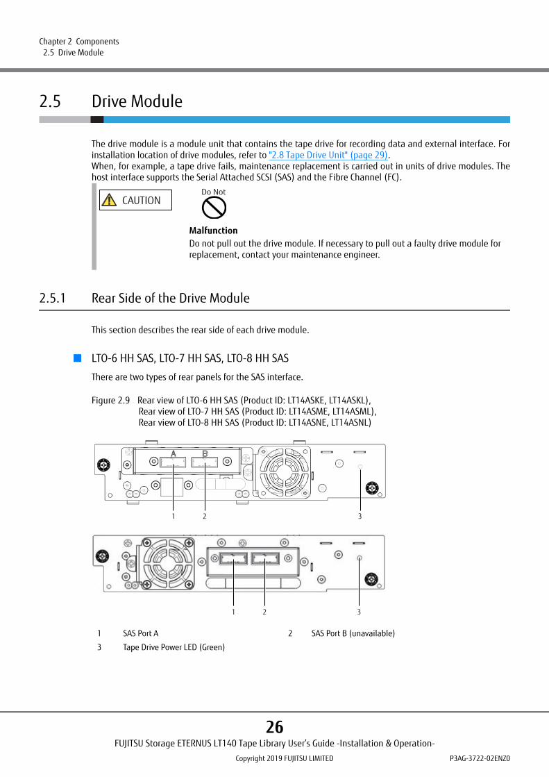
■ LTO-6 HH SAS, LTO-7 HH SAS, LTO-8 HH SAS
There are two types of rear panels for the SAS interface.
Figure 2.9 Rear view of LTO-6 HH SAS (Product ID: LT14ASKE, LT14ASKL),Rear view of LTO-7 HH SAS (Product ID: LT14ASME, LT14ASML),Rear view of LTO-8 HH SAS (Product ID: LT14ASNE, LT14ASNL)
CAUTIONDo Not
MalfunctionDo not pull out the drive module. If necessary to pull out a faulty drive module for replacement, contact your maintenance engineer.
1 SAS Port A 2 SAS Port B (unavailable)
3 Tape Drive Power LED (Green)
321
321
FUJITSU Storage ETERNUS LT140 Tape Library User’s Guide -Installation & Operation-
Copyright 2019 FUJITSU LIMITED P3AG-3722-02ENZ0
26
Chapter 2 Components 2.6 Robotic Assembly
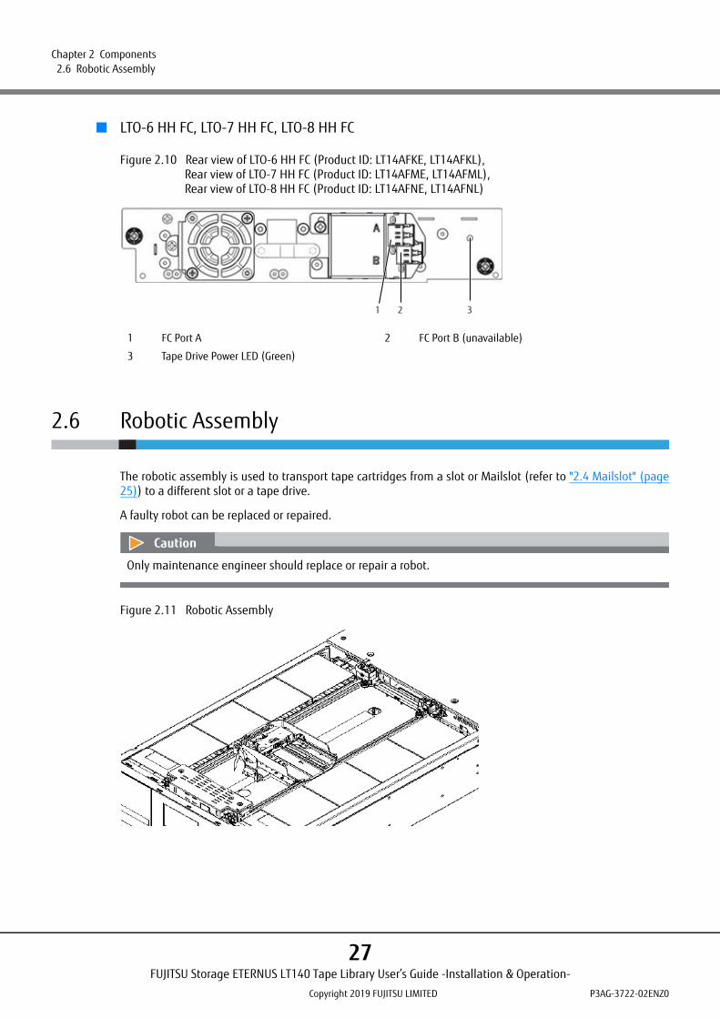
■ LTO-6 HH FC, LTO-7 HH FC, LTO-8 HH FC
Figure 2.10 Rear view of LTO-6 HH FC (Product ID: LT14AFKE, LT14AFKL), Rear view of LTO-7 HH FC (Product ID: LT14AFME, LT14AFML), Rear view of LTO-8 HH FC (Product ID: LT14AFNE, LT14AFNL)
2.6 Robotic Assembly
The robotic assembly is used to transport tape cartridges from a slot or Mailslot (refer to "2.4 Mailslot" (page25)) to a different slot or a tape drive.
A faulty robot can be replaced or repaired.
Figure 2.11 Robotic Assembly
1 FC Port A 2 FC Port B (unavailable)
3 Tape Drive Power LED (Green)
321
Only maintenance engineer should replace or repair a robot.
FUJITSU Storage ETERNUS LT140 Tape Library User’s Guide -Installation & Operation-
Copyright 2019 FUJITSU LIMITED P3AG-3722-02ENZ0
27
Chapter 2 Components 2.7 Library Controller
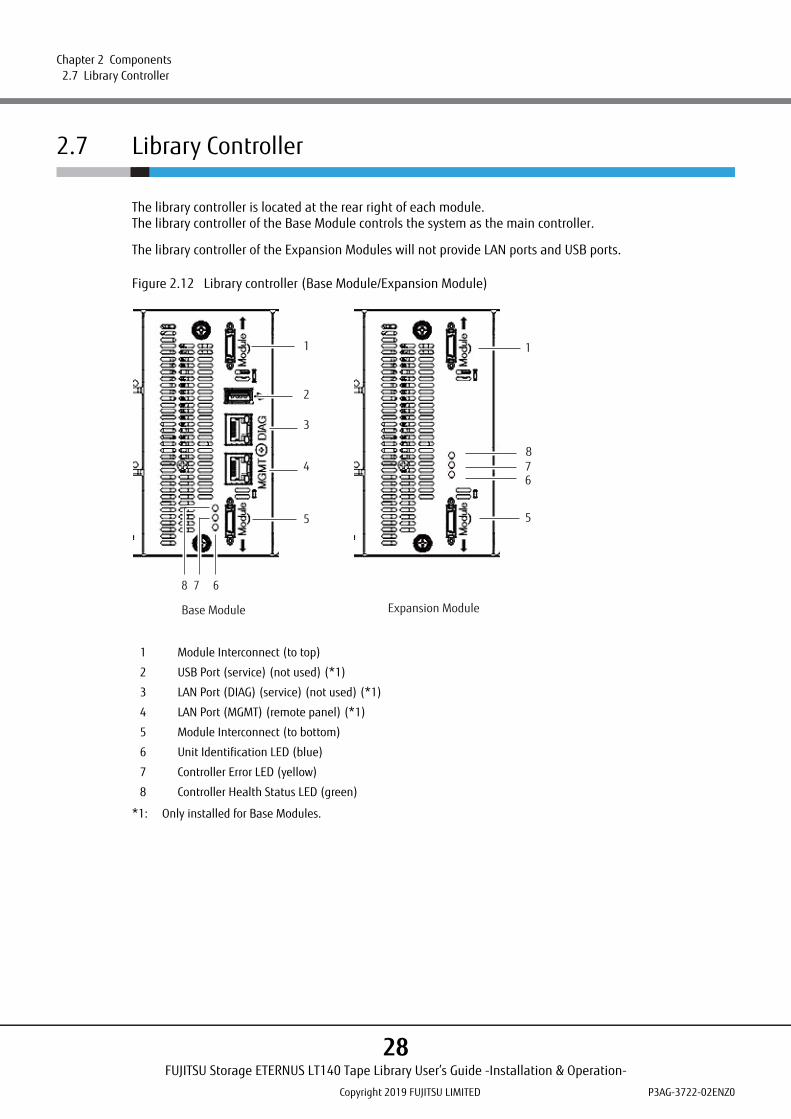
2.7 Library Controller
The library controller is located at the rear right of each module.The library controller of the Base Module controls the system as the main controller.
The library controller of the Expansion Modules will not provide LAN ports and USB ports.
Figure 2.12 Library controller (Base Module/Expansion Module)
*1: Only installed for Base Modules.
1 Module Interconnect (to top)
2 USB Port (service) (not used) (*1)
3 LAN Port (DIAG) (service) (not used) (*1)
4 LAN Port (MGMT) (remote panel) (*1)
5 Module Interconnect (to bottom)
6 Unit Identification LED (blue)
7 Controller Error LED (yellow)
8 Controller Health Status LED (green)
1
2
3
4
5
678
1
678
5
Base Module Expansion Module
FUJITSU Storage ETERNUS LT140 Tape Library User’s Guide -Installation & Operation-
Copyright 2019 FUJITSU LIMITED P3AG-3722-02ENZ0
28

Chapter 2 Components 2.8 Tape Drive Unit
Table 2.7 Meanings of each LED (library controller)
2.8 Tape Drive Unit
Up to 3 half height drives can be installed in the tape drive unit. Power is supplied to the tape drive with adrive power board.
Figure 2.13 Tape drive unit and drive power board
● Drive module
For details on the drive module, refer to "2.5 Drive Module" (page 26).
No. LED status Meaning
6 Unit Identifier LED Blue The LED of the Unit ID (UID) is controlled by the user with the Maintenance > UID LED Control screen of the operator panel or remote panel.The UID LED can be used for identifying the location of the data center library.
7 Controller Error LED Yellow When lit, the controller is not functioning.
8 Controller Health Status LED
Green When the state of the library controller is normal, the LED flashes green.
1 Drive power board (behind library controller)
2 Half-Height Tape Drive Bay
12
FUJITSU Storage ETERNUS LT140 Tape Library User’s Guide -Installation & Operation-
Copyright 2019 FUJITSU LIMITED P3AG-3722-02ENZ0
29
Chapter 2 Components 2.9 Power Supply Unit (PSU)
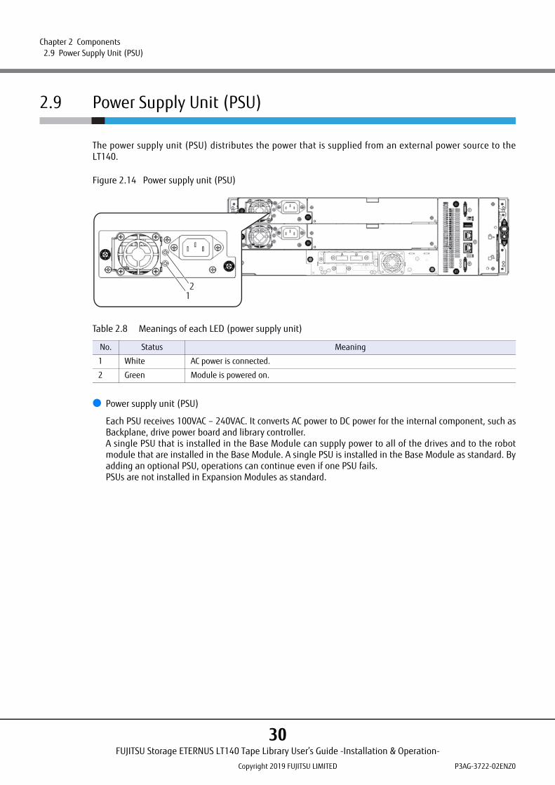
2.9 Power Supply Unit (PSU)
The power supply unit (PSU) distributes the power that is supplied from an external power source to theLT140.
Figure 2.14 Power supply unit (PSU)
Table 2.8 Meanings of each LED (power supply unit)
● Power supply unit (PSU)
Each PSU receives 100VAC – 240VAC. It converts AC power to DC power for the internal component, such asBackplane, drive power board and library controller.A single PSU that is installed in the Base Module can supply power to all of the drives and to the robotmodule that are installed in the Base Module. A single PSU is installed in the Base Module as standard. Byadding an optional PSU, operations can continue even if one PSU fails.PSUs are not installed in Expansion Modules as standard.
No. Status Meaning
1 White AC power is connected.
2 Green Module is powered on.
12
FUJITSU Storage ETERNUS LT140 Tape Library User’s Guide -Installation & Operation-
Copyright 2019 FUJITSU LIMITED P3AG-3722-02ENZ0
30
Chapter 3
Basic Operation
This chapter explains how to perform basic daily operations.
3.1 Powering On/Off
This section explains how to turn on and off the LT140.
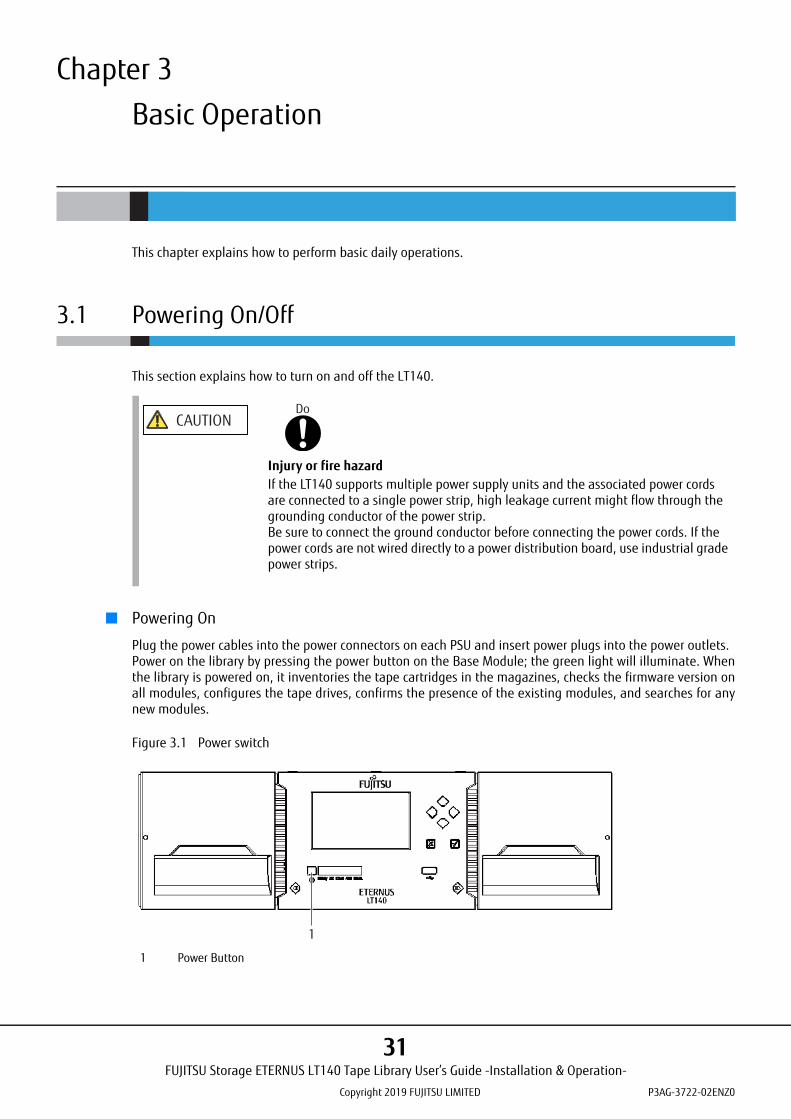
■ Powering On
Plug the power cables into the power connectors on each PSU and insert power plugs into the power outlets.Power on the library by pressing the power button on the Base Module; the green light will illuminate. Whenthe library is powered on, it inventories the tape cartridges in the magazines, checks the firmware version onall modules, configures the tape drives, confirms the presence of the existing modules, and searches for anynew modules.
Figure 3.1 Power switch
CAUTIONDo
Injury or fire hazardIf the LT140 supports multiple power supply units and the associated power cords are connected to a single power strip, high leakage current might flow through the grounding conductor of the power strip.Be sure to connect the ground conductor before connecting the power cords. If the power cords are not wired directly to a power distribution board, use industrial grade power strips.
1 Power Button
1
FUJITSU Storage ETERNUS LT140 Tape Library User’s Guide -Installation & Operation-
Copyright 2019 FUJITSU LIMITED P3AG-3722-02ENZ0
31
Chapter 3 Basic Operation 3.1 Powering On/Off
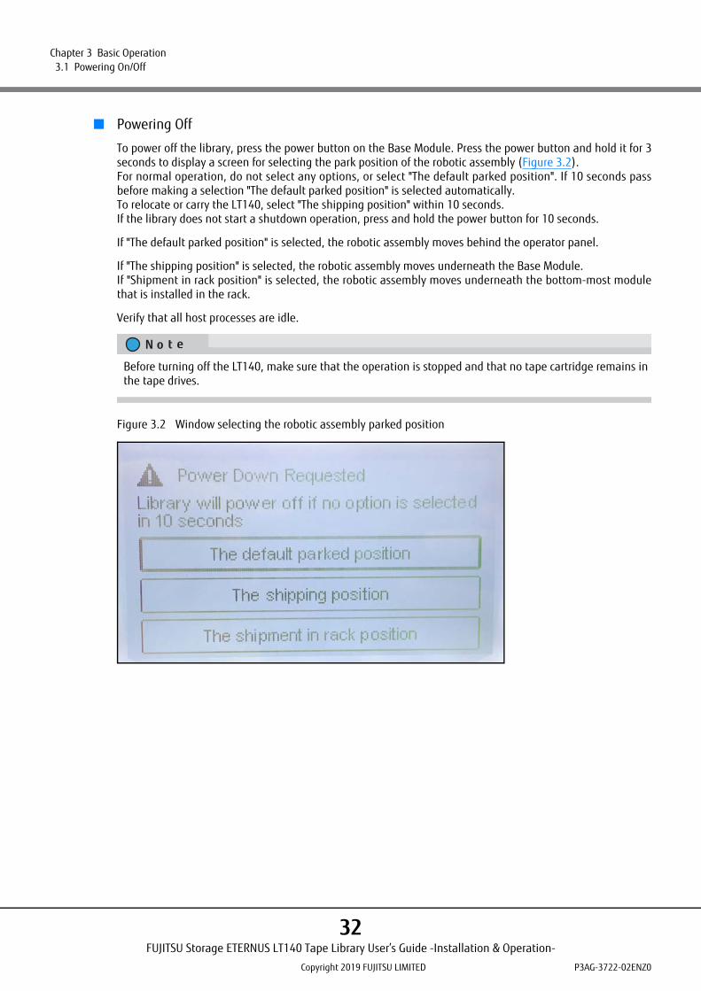
■ Powering Off
To power off the library, press the power button on the Base Module. Press the power button and hold it for 3seconds to display a screen for selecting the park position of the robotic assembly (Figure 3.2).For normal operation, do not select any options, or select "The default parked position". If 10 seconds passbefore making a selection "The default parked position" is selected automatically.To relocate or carry the LT140, select "The shipping position" within 10 seconds.If the library does not start a shutdown operation, press and hold the power button for 10 seconds.
If "The default parked position" is selected, the robotic assembly moves behind the operator panel.
If "The shipping position" is selected, the robotic assembly moves underneath the Base Module.If "Shipment in rack position" is selected, the robotic assembly moves underneath the bottom-most modulethat is installed in the rack.
Verify that all host processes are idle.
Figure 3.2 Window selecting the robotic assembly parked position
Before turning off the LT140, make sure that the operation is stopped and that no tape cartridge remains in the tape drives.
FUJITSU Storage ETERNUS LT140 Tape Library User’s Guide -Installation & Operation-
Copyright 2019 FUJITSU LIMITED P3AG-3722-02ENZ0
32
Chapter 3 Basic Operation 3.1 Powering On/Off
3.1.1 Points to Note when Turning On or Turning Off the LT140
3.1.2 Turning on the Server
If the server power is turned on while the library is initializing, a library identification error might result. Besure to allow the library to finish its initialization sequence before turning on the server power.
CAUTIONDo Not
Data destructionDo not ever run backup software while the library power is being turned off or a power-on initialization sequence is in progress. Otherwise, a malfunction may result.If the library power is turned off while a backup is in progress, the validity of the data being written is not guaranteed. In addition, the tape cartridges to which data has been written might become unusable. If these problems occur, contact the support department of the backup software vendor and take their suggested corrective actions before retrying the backup.
FUJITSU Storage ETERNUS LT140 Tape Library User’s Guide -Installation & Operation-
Copyright 2019 FUJITSU LIMITED P3AG-3722-02ENZ0
33

Chapter 3 Basic Operation 3.2 Operator Panel Operation
3.2 Operator Panel Operation
This section describes the login method and the screen configuration of the operator panel.
3.2.1 Logging into the Library
This section explains how to login to the library:
Procedure
1 Display the login screen.Press the Enter button to exit the screen saver if it is being displayed on the operator panel.
2 Select a user.
Figure 3.3 Login screen
3 If required, enter the PIN.
4 Select Login.The user levels are:
• userThe user account provides access to status information, but not configuration, maintenance oroperation functions. There is no initial PIN. Log in to the library without entering a PIN.In addition, the administrator account can set a user account PIN, allow or deny the use of someoperation functions. For details, refer to "2.5.5 Changing the PIN" in "FUJITSU Storage ETERNUSLT140 Tape Library User's Guide -Panel Operation-".
FUJITSU Storage ETERNUS LT140 Tape Library User’s Guide -Installation & Operation-
Copyright 2019 FUJITSU LIMITED P3AG-3722-02ENZ0
34
Chapter 3 Basic Operation 3.2 Operator Panel Operation
• administratorThe administrator PIN is required to login as the administrative user. An initial administrator PIN isnot set. Log in to the library without entering a PIN.The administrator user can use most functions except for the log configuration function and themaintenance function.
• securityThe "security" account cannot log in to the library from the operator panel. When logging in to thelibrary with the "security" account, use the remote panel.For details, refer to "3.2 Logging into the Library" in "FUJITSU Storage ETERNUS LT140 Tape LibraryUser's Guide -Panel Operation-".
• serviceAccess to this user is by Service personnel only. The service PIN is set at the factory.
End of procedure
For security purposes, changing the initial administrator PIN after starting the library is recommended.During the initial login, the Initial System Setup function is used to configure the library and set the administrator PIN. The remote panel can be used by changing the administrator PIN and by configuring the network settings with this function.For more details, refer to "3.4.1 Using Initial System Setup" (page 39).
Basically, only one user can log in to the library regardless of whether the user logs in from the remote panel or operator panel.If a user is already logged in, a warning message appears. Select whether to continue the login process.
• Select Leave to stop the login process.• Select Login to continue the login process and forcibly log the currently logged in user out.
As an exception, only the "user" account can log in to the library regardless of whether other users are logged in.Note that if no operation is performed for a certain period of time, the user is forcibly logged out.
FUJITSU Storage ETERNUS LT140 Tape Library User’s Guide -Installation & Operation-
Copyright 2019 FUJITSU LIMITED P3AG-3722-02ENZ0
35
Chapter 3 Basic Operation 3.2 Operator Panel Operation
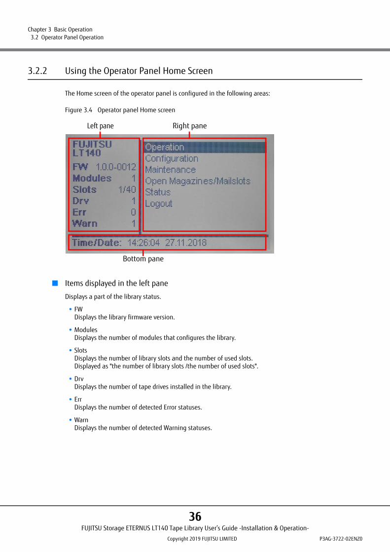
3.2.2 Using the Operator Panel Home Screen
The Home screen of the operator panel is configured in the following areas:
Figure 3.4 Operator panel Home screen
■ Items displayed in the left pane
Displays a part of the library status.
• FWDisplays the library firmware version.
• ModulesDisplays the number of modules that configures the library.
• SlotsDisplays the number of library slots and the number of used slots.Displayed as "the number of library slots /the number of used slots".
• DrvDisplays the number of tape drives installed in the library.
• ErrDisplays the number of detected Error statuses.
• WarnDisplays the number of detected Warning statuses.
Left pane
Bottom pane
Right pane
FUJITSU Storage ETERNUS LT140 Tape Library User’s Guide -Installation & Operation-
Copyright 2019 FUJITSU LIMITED P3AG-3722-02ENZ0
36
Chapter 3 Basic Operation 3.2 Operator Panel Operation
■ Items displayed in the right pane
Displays the operation menu list.
• Operation (non-user account)Using the operation function of the library. For more details, refer to "3.3 Operating the Library" (page 38).
• Configuration (non-user account)Configuring the library. For more details, refer to "3.4 Configuring the Library" (page 39).
• Maintenance (non-user account)Using the maintenance function of the library. For details, refer to "2.6 Maintaining the Library" in "FUJITSUStorage ETERNUS LT140 Tape Library User's Guide -Panel Operation-".
• Open Magazines/MailslotsUses the magazines or Mailslots of the library. For more details, refer to "3.5 Loading and Ejecting TapeCartridges" (page 41).
• StatusReferencing the library status information. For details, refer to "2.8 Viewing the Library Information" in"FUJITSU Storage ETERNUS LT140 Tape Library User's Guide -Panel Operation-".
• LogoutLogging out to return to the login screen.
■ Items displayed in the bottom pane
Displays information such as the IP addresses that are set for the library or the date and time in sequence.
FUJITSU Storage ETERNUS LT140 Tape Library User’s Guide -Installation & Operation-
Copyright 2019 FUJITSU LIMITED P3AG-3722-02ENZ0
37

Chapter 3 Basic Operation 3.3 Operating the Library
3.3 Operating the Library
This section describes the library operation functions.Select Operation in the Home screen to use the operation functions of the library from the menu that is dis-played.
3.3.1 Moving Media
From the Operation > Move Media screen you can move a tape cartridge located in a source element to anavailable destination element within the same partition.
Procedure
1 Press the Enter button in the Operation > Move Media screen.
2 Select a cartridge from the Source Elements list.
3 Select the destination location from Destination Elements list.
4 When the confirmation screen for the operation appears, select Submit.
End of procedure
3.3.2 Moving the Media from the Tape Drive to a Slot
In the Operation > Move Cartridge from Drive to Slot screen, the tape cartridge can be moved back to itsoriginal slot prior to being mounted in the tape drive.
Procedure
1 From the list of tape drives, select the tape drive from which the tape cartridge is to be ejected.
2 Press the Enter button.
End of procedure
3.3.3 Rescanning the Cartridge Inventory
Rescan the tape cartridge using the library from the Operation > Inventory Scan screen.To rescan the tape cartridge using the library, press the Enter button. The library changes to the Scanningstate. Other operations cannot be performed until the scan is completed.
FUJITSU Storage ETERNUS LT140 Tape Library User’s Guide -Installation & Operation-
Copyright 2019 FUJITSU LIMITED P3AG-3722-02ENZ0
38
Chapter 3 Basic Operation 3.4 Configuring the Library
3.4 Configuring the Library
This section explains about the library configuration.Perform a library configuration. To display the menu, select Configuration in the Home screen.
3.4.1 Using Initial System Setup
By using the wizard from the Configuration > Initial System Setup screen, the library network settings, thedate and time, and the administrator PIN can be configured. Items can be skipped or the wizard can bestopped at any time. If the network configuration is completed, the remaining configuration can beperformed from the remote panel using the Initial Configuration Wizard.
3.4.2 Setting the Date and Time
The date and time can be set from the Configuration > Date & Time screen.
Procedure
1 Select Date to enter the date. Enter the date in order of day, month, and year.
2 Select Time to enter the time. Enter the time in order of hour, minute, and second.
3 Select Submit and press the Enter button.
End of procedure
Configuring the library with this function during the initial login is recommended. Therefore, a message recommending the use of this function is displayed when logged in for the first time. Until settings are completed with this function, the message is displayed every time the user logs in to the operator panel.
FUJITSU Storage ETERNUS LT140 Tape Library User’s Guide -Installation & Operation-
Copyright 2019 FUJITSU LIMITED P3AG-3722-02ENZ0
39
Chapter 3 Basic Operation 3.4 Configuring the Library
3.4.3 Tape Drive Power Operation
In the Configuration > Drive Power On/Off screen, the power of the tape drive that is installed in the librarycan be turned on or off.
Procedure
1 Select the target tape drive.
2 If there are no problems with the information of the selected tape drive that is displayed, press the Enter button.
3 When the confirmation screen for the operation appears, select Yes.
End of procedure
FUJITSU Storage ETERNUS LT140 Tape Library User’s Guide -Installation & Operation-
Copyright 2019 FUJITSU LIMITED P3AG-3722-02ENZ0
40

Chapter 3 Basic Operation 3.5 Loading and Ejecting Tape Cartridges
3.5 Loading and Ejecting Tape Cartridges
This section explains how to insert and eject a tape cartridge.
3.5.1 Unlocking the Magazine or Mailslot
This section explains how to open the magazine or Mailslot:The front panel of the LT140 has magazine open buttons that correspond to the left and right magazines.
To unlock and open the magazines and Mailslots, use the magazine/Mailslot open button after logging in tothe operator panel and accessing Open Magazines/Mailslots of the Home screen.
Procedure
1 Log in to the Home screen (refer to "3.2.1 Logging into the Library" (page 34)).
If a logical library is configured, make sure to eject the target tape cartridge and load a tape cartridge in the slot of the correct partition.Check the following points before opening the Mailslot.
• The number and position of the Mailslot to be opened• The number and position of the slot where a tape cartridge is to be loaded or ejected• The slot location of each partition
For details about how to check the above information, refer to "3.7.3 Using Inventory Graphical View" and "3.7.4 Partition Map Graphical View" in "FUJITSU Storage ETERNUS LT140 Tape Library User’s Guide -Panel Operation-".
Some of the slots in the right magazines can be configured as the Mailslots.Refer to "3.4.12 Enabling or Disabling Mailslots" in "FUJITSU Storage ETERNUS LT140 Tape Library User’s Guide -Panel Operation-" for the detailed settings.
FUJITSU Storage ETERNUS LT140 Tape Library User’s Guide -Installation & Operation-
Copyright 2019 FUJITSU LIMITED P3AG-3722-02ENZ0
41
Chapter 3 Basic Operation 3.5 Loading and Ejecting Tape Cartridges
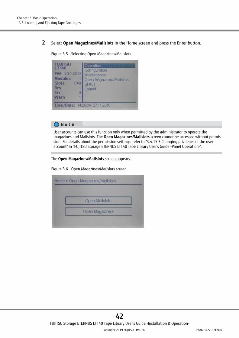
2 Select Open Magazines/Mailslots in the Home screen and press the Enter button.
Figure 3.5 Selecting Open Magazines/Mailslots
The Open Magazines/Mailslots screen appears.
Figure 3.6 Open Magazines/Mailslots screen
User accounts can use this function only when permitted by the administrator to operate the magazines and Mailslots. The Open Magazines/Mailslots screen cannot be accessed without permis-sion. For details about the permission settings, refer to "3.4.15.3 Changing privileges of the user account" in "FUJITSU Storage ETERNUS LT140 Tape Library User's Guide -Panel Operation-".
FUJITSU Storage ETERNUS LT140 Tape Library User’s Guide -Installation & Operation-
Copyright 2019 FUJITSU LIMITED P3AG-3722-02ENZ0
42

Chapter 3 Basic Operation 3.5 Loading and Ejecting Tape Cartridges
3 Select the target component to open.To open a magazine, select Open Magazines and press the Enter button. To open a Mailslot, selectOpen Mailslots and press the Enter button.
The notification screen for opening the magazine/Mailslot is displayed and the LED of the target maga-zine/Mailslot is lit. The notification screen automatically closes.
Figure 3.7 Open Magazines/Mailslots notification screen
User accounts can select only the components that they are permitted to open.
FUJITSU Storage ETERNUS LT140 Tape Library User’s Guide -Installation & Operation-
Copyright 2019 FUJITSU LIMITED P3AG-3722-02ENZ0
43

Chapter 3 Basic Operation 3.5 Loading and Ejecting Tape Cartridges
4 Press the magazine/Mailslot open button that corresponds to the target magazine/Mailslot to unlock and open.
Figure 3.8 Magazine/Mailslot
Table 3.1 Details of the magazine open buttons
End of procedure
1 Left magazine open button, status LED (blue)
2 Right magazine/Mailslot open button, status LED (blue)
LED status Description
Off The magazine/Mailslot open button is disabled
Flashing (slow) The magazine lock is being released
Flashing (fast) The magazine is unlocked
On The magazine/Mailslot open button is enabled
• For details on each parts of the operator panel or buttons, refer to "1.1.1 Overview of the Operator Panel" in "FUJITSU Storage ETERNUS LT140 Tape Library User's Guide -Panel Operation-".
• If the LED is on, magazines and Mailslots can be opened.• If the currently logged in user logs out, the LED turns off and the magazines and Mailslot cannot
be opened.
11 2
FUJITSU Storage ETERNUS LT140 Tape Library User’s Guide -Installation & Operation-
Copyright 2019 FUJITSU LIMITED P3AG-3722-02ENZ0
44
Chapter 3 Basic Operation 3.5 Loading and Ejecting Tape Cartridges
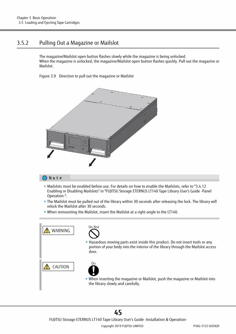
3.5.2 Pulling Out a Magazine or Mailslot
The magazine/Mailslot open button flashes slowly while the magazine is being unlocked.When the magazine is unlocked, the magazine/Mailslot open button flashes quickly. Pull out the magazine orMailslot.
Figure 3.9 Direction to pull out the magazine or Mailslot
• Mailslots must be enabled before use. For details on how to enable the Mailslots, refer to "3.4.12 Enabling or Disabling Mailslots" in "FUJITSU Storage ETERNUS LT140 Tape Library User's Guide -Panel Operation-".
• The Mailslot must be pulled out of the library within 30 seconds after releasing the lock. The library will relock the Mailslot after 30 seconds.
• When remounting the Mailslot, insert the Mailslot at a right angle to the LT140.
WARNINGDo Not
• Hazardous moving parts exist inside this product. Do not insert tools or any portion of your body into the interior of the library through the Mailslot access door.
CAUTIONDo
• When inserting the magazine or Mailslot, push the magazine or Mailslot into the library slowly and carefully.
FUJITSU Storage ETERNUS LT140 Tape Library User’s Guide -Installation & Operation-
Copyright 2019 FUJITSU LIMITED P3AG-3722-02ENZ0
45
Chapter 3 Basic Operation 3.5 Loading and Ejecting Tape Cartridges
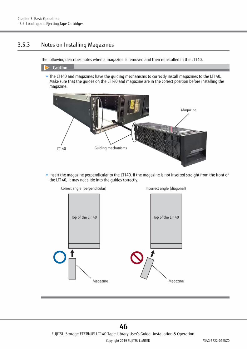
3.5.3 Notes on Installing Magazines
The following describes notes when a magazine is removed and then reinstalled in the LT140.
• The LT140 and magazines have the guiding mechanisms to correctly install magazines to the LT140.Make sure that the guides on the LT140 and magazine are in the correct position before installing the magazine.
• Insert the magazine perpendicular to the LT140. If the magazine is not inserted straight from the front of the LT140, it may not slide into the guides correctly.
LT140
Magazine
Guiding mechanisms
Magazine
Top of the LT140
Magazine
Correct angle (perpendicular) Incorrect angle (diagonal)
Top of the LT140
FUJITSU Storage ETERNUS LT140 Tape Library User’s Guide -Installation & Operation-
Copyright 2019 FUJITSU LIMITED P3AG-3722-02ENZ0
46

Chapter 3 Basic Operation 3.5 Loading and Ejecting Tape Cartridges
● Correct installation of the guides
If the guides are in the correct position, the guides of the LT140 will be caught by the guides of themagazine.If the guides are in this position, the magazine can be inserted smoothly.
Figure 3.10 Inserting magazines (correct guide position)
CAUTIONDo
• If the guides are not in the correct position, the magazine may get stuck and not be inserted smoothly. If the magazine gets stuck, pull it out and reinsert it. If the magazine is forced in, it may become immovable and damage the LT140.
LT140
Magazine
FUJITSU Storage ETERNUS LT140 Tape Library User’s Guide -Installation & Operation-
Copyright 2019 FUJITSU LIMITED P3AG-3722-02ENZ0
47
Chapter 3 Basic Operation 3.5 Loading and Ejecting Tape Cartridges
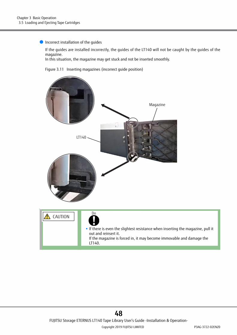
● Incorrect installation of the guides
If the guides are installed incorrectly, the guides of the LT140 will not be caught by the guides of themagazine.In this situation, the magazine may get stuck and not be inserted smoothly.
Figure 3.11 Inserting magazines (incorrect guide position)
CAUTIONDo
• If there is even the slightest resistance when inserting the magazine, pull it out and reinsert it.If the magazine is forced in, it may become immovable and damage the LT140.
LT140
Magazine
FUJITSU Storage ETERNUS LT140 Tape Library User’s Guide -Installation & Operation-
Copyright 2019 FUJITSU LIMITED P3AG-3722-02ENZ0
48

Chapter 3 Basic Operation 3.5 Loading and Ejecting Tape Cartridges
3.5.4 Inserting Tape Cartridges
This section explains how to insert tape cartridges.
Procedure
1 Insert a tape cartridge into the Mailslot or magazine.Insert the tape cartridge into the correct direction as shown in Figure 3.12. When the direction iscorrect, the barcode label faces the front (direction in which the robot can read). In addition, the reelsurface of the cartridge faces downward. The hand section can be moved by hand. When manuallyinserting a tape cartridge into the slot, insert it such that it has the correct orientation by checking thefollowing points:
• The barcode label faces the front (direction in which the robot can read).• The reel surface of the cartridge faces downward.
.
Figure 3.12 Tape cartridge insertion direction
2 After inserting the tape cartridge into the Mailslot or the magazine, re-insert the Mailslot or magazine into the LT140.The LT140 automatically performs inventory operation.The management information of tape cartridges managed by the LT140 is updated, and the LT140goes back on-line.
3 Perform the inventory operation of the backup software to update the tape cartridge management information for cartridges held by the backup software.
End of procedure
A barcode label must be affixed to the tape cartridge so that management information can be differentiated for each individual tape cartridge.
Confirm the direction of the symbol ( )
and correctly insert the cartridge.
(This symbol indicates the correct direction.)
FUJITSU Storage ETERNUS LT140 Tape Library User’s Guide -Installation & Operation-
Copyright 2019 FUJITSU LIMITED P3AG-3722-02ENZ0
49

Chapter 3 Basic Operation 3.5 Loading and Ejecting Tape Cartridges
CAUTIONDo
Damage to the LT140Never insert a tape cartridge in the wrong direction and never insert an out-of-spec tape cartridge. Otherwise, the robot may be damaged.The robot may not operate normally if a tape cartridge is inserted into any slot other than the specified one. The insertion location of tape cartridges differs by model.
Do
MalfunctionIf a Mailslot containing inserted tape cartridges is positioned with the tape cartridge storage shelves facing downward and the Mailslot is subject to impact, the tape cartridges may fall out of the Mailslot. To prevent this from occurring, do not position the Mailslot with the tape cartridge storage shelves facing downward when carrying the Mailslot.
FUJITSU Storage ETERNUS LT140 Tape Library User’s Guide -Installation & Operation-
Copyright 2019 FUJITSU LIMITED P3AG-3722-02ENZ0
50

Chapter 3 Basic Operation 3.6 Cleaning Tape Drives
3.6 Cleaning Tape Drives
There are two methods for cleaning the magnetic head of the tape drive: one is "manual cleaning", which isoperated from the remote panel; the other is "auto-cleaning with the backup software", which automaticallyperforms a cleaning for the specified number of times.To perform a cleaning with the backup software, one cleaning cartridge must be stored in the tape library atall times. Note that the number of data cartridges that can be stored is reduced by one.
3.6.1 Auto-Cleaning with the Backup Software
Use the backup software to clean tape drives periodically. Since the cleaning cartridge that is used by thismethod is managed by the backup software, the cleaning cartridge must be stored in slots of the LT140.
Refer to the manuals of each software for the detailed settings of the backup software.
■ Notes for cleaning with the backup software during a backup operation
For cleanings with the backup software, perform a tape drive cleaning when no other backup operation(backup/restore) is being performed in the target tape drive.
Although some backup software allows cleaning management during the operation, the actual cleaningstarts after the backup is complete.
To perform auto-cleaning with NetVault, individual settings are required. For details, refer to "4.5 NetVault" in "FUJITSU Storage ETERNUS LT140 Tape Library User's Guide -Server Connection-".
CAUTIONDamage to the LT140 and data destructionIf incorrect settings are applied for auto-cleaning with the backup software, the LT140 or the tape cartridge may become damaged, or data destruction may occur.Understand the setting contents before performing a configuration.
MalfunctionDuring a cleaning operation with the backup software, "DRIVE CLN" is displayed on the operator panel, but it is not displayed on the remote panel.Logging in to the remote panel may not be allowed if a cleaning with the backup software is being performed.In this case, a login is allowed after the cleaning is complete.
FUJITSU Storage ETERNUS LT140 Tape Library User’s Guide -Installation & Operation-
Copyright 2019 FUJITSU LIMITED P3AG-3722-02ENZ0
51

Chapter 3 Basic Operation 3.6 Cleaning Tape Drives
3.6.2 Cleaning Tape Drives Manually
Request the cleaning of tape drives from the remote panel of the LT140. This method must be performedevery time cleaning of the tape drives is required. In this method, the cleaning cartridges that are stored inthe slots of the LT140 are used.
This section explains how to clean the tape drive.
Procedure
1 From the Operation > Clean Drive screen, initiate a tape drive cleaning operation.
Figure 3.13 Clean Drive screen
2 Select a cleaning cartridge from the Source Elements list.The library uses the barcode label to identify cleaning cartridges.If no cleaning cartridges are available, load one into a Mailslot or slot.
3 Select a cleaning cartridge from the Source Elements list.Tape drives currently containing a cartridge are not listed. To clean a tape drive not listed, move thecartridge out of the drive.
4 Click Submit.
End of procedure
FUJITSU Storage ETERNUS LT140 Tape Library User’s Guide -Installation & Operation-
Copyright 2019 FUJITSU LIMITED P3AG-3722-02ENZ0
52

Chapter 4
Default Setting
This chapter explains how to make the minimum settings required during installation of the LT140.Although this chapter explains how to configure the settings using the operator panel, the same settings canbe configured from the remote panel after the network is configured.For details on this setting method, refer to "FUJITSU Storage ETERNUS LT140 Tape Library User's Guide -PanelOperation-".
4.1 Login
Log in with the administrator account from the operator panel.
Procedure
1 Display the login screen.If the screensaver is on, press the Enter button to turn it off.
Figure 4.1 Screensaver screen
FUJITSU Storage ETERNUS LT140 Tape Library User’s Guide -Installation & Operation-
Copyright 2019 FUJITSU LIMITED P3AG-3722-02ENZ0
53

Chapter 4 Default Setting 4.1 Login
2 From Select User, use the up and down buttons to select the administrator.
Figure 4.2 Select User selection screen
3 Select Enter PIN and use the up and down buttons or the left and right buttons to enter the administrator PIN.There is no default administrator PIN. Log in without a PIN.
Figure 4.3 Enter PIN screen
4 Select Login and press the Enter button.
Figure 4.4 Enter PIN confirmation screen
FUJITSU Storage ETERNUS LT140 Tape Library User’s Guide -Installation & Operation-
Copyright 2019 FUJITSU LIMITED P3AG-3722-02ENZ0
54

Chapter 4 Default Setting 4.1 Login
Move to the Home screen.
Figure 4.5 Home screen
5 On the Home screen of the operator panel, select Configuration and press the Enter button.
Figure 4.6 Configuration selection screen
Move to the Configuration screen.
End of procedure
FUJITSU Storage ETERNUS LT140 Tape Library User’s Guide -Installation & Operation-
Copyright 2019 FUJITSU LIMITED P3AG-3722-02ENZ0
55

Chapter 4 Default Setting 4.2 Using the Initial System Setup
4.2 Using the Initial System Setup
By using the wizard from the Configuration > Initial System Setup screen, the library network settings, thedate and time, and the administrator PIN can be configured. If the network settings are completed,operations can be performed from the remote panel. During the initial login, configuring the library with thisfunction is recommended.
Figure 4.7 Initial Configuration screen
To set the library configuration, perform the following procedure:
Procedure
1 On the Configuration > Initial System Setup screen, select Next and press Enter.
For internal communication between modules, the tape library uses an Ethernet connection with an internal IP address range.The initial internal IP address range is 192.0.2.0/24. If a conflict with the external Ethernet port occurs, the internal IP address range setting must be changed. For details about how to change the setting, refer to the "2.5.8 Resetting the IP Range" in "FUJITSU Storage ETERNUS LT140 Tape Library User’s Guide -Panel Opera-tion-".
Items whose settings are not changed can be skipped by selecting Next without entering a value.
FUJITSU Storage ETERNUS LT140 Tape Library User’s Guide -Installation & Operation-
Copyright 2019 FUJITSU LIMITED P3AG-3722-02ENZ0
56

Chapter 4 Default Setting 4.2 Using the Initial System Setup
2 Configure the network.
Figure 4.8 Network Configuration screen
• Host NameEnter a value.
• Domain NameEnter a value.
• ProtocolSelect a protocol to use from the drop-down list.
For the selected protocol, enter the remaining setting values.
3 After entering the values, select Next and press Enter.
4 Set the date and time.
Figure 4.9 Date / Time Configuration screen
• Date (DD.MM.YYYY)Set the date. Enter the day, month, and year.
• Time (HH:MM:SS 24hr)Set the time. Enter the hour, minute, and second.
After entering the values, select Next and press Enter.
To automatically obtain an IP address for the library, select DHCP (for IPv4) or Stateless (for IPv6) in Method.
FUJITSU Storage ETERNUS LT140 Tape Library User’s Guide -Installation & Operation-
Copyright 2019 FUJITSU LIMITED P3AG-3722-02ENZ0
57
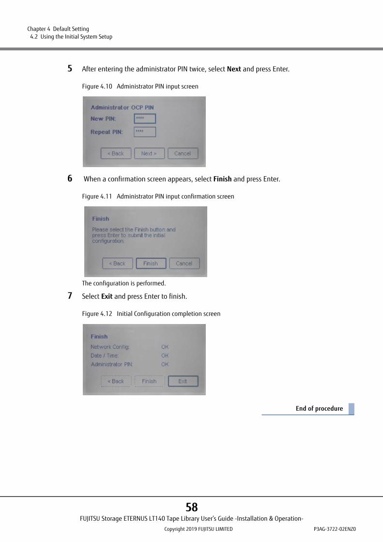
Chapter 4 Default Setting 4.2 Using the Initial System Setup
5 After entering the administrator PIN twice, select Next and press Enter.
Figure 4.10 Administrator PIN input screen
6 When a confirmation screen appears, select Finish and press Enter.
Figure 4.11 Administrator PIN input confirmation screen
The configuration is performed.
7 Select Exit and press Enter to finish.
Figure 4.12 Initial Configuration completion screen
End of procedure
FUJITSU Storage ETERNUS LT140 Tape Library User’s Guide -Installation & Operation-
Copyright 2019 FUJITSU LIMITED P3AG-3722-02ENZ0
58

Chapter 4 Default Setting 4.3 Saving and Restoring the Library Configuration Setting File
4.3 Saving and Restoring the Library Configuration Setting File
For the LT140, the library configuration setting can be saved as a file or restored using the remote panel. Forthe operation procedure, refer to "3.4.2 Saving, Restoring and Resetting the Library Configuration" in "FujitsuStorage ETERNUS LT140 Tape Library User's Guide -Panel Operation-".
When the library is configured or set after purchasing the LT140 or when the library configuration or setting is changed during operation, make sure to save the library configuration settings as a file. The saved library configuration setting file can be restored by using the operator panel or the remote panel. Keep the latest library configuration setting file in a safe location. This file may be required for maintenance. Saving the library configuration setting file once a year is recommended.
FUJITSU Storage ETERNUS LT140 Tape Library User’s Guide -Installation & Operation-
Copyright 2019 FUJITSU LIMITED P3AG-3722-02ENZ0
59

Chapter 5
Monitoring the LT140 Status
This chapter explains how to check the LT140 status and what information is reported.
5.1 Operator Panel
LT140 status can be checked using the status LEDs on the front of the Base Module.For details, refer to "Status LEDs" (page 22) in "2.2 Operator Panel" (page 22).
5.2 Remote Panel
The Home screen is configure in the following areas:
• Top bannerContains the home button and displays the overall status and information about the library and user.
• Left paneDisplays the library identity and module status.
• Center paneProvides access to operate and configure the library and to view additional status information.
• Right paneDisplays a log of recent events.
FUJITSU Storage ETERNUS LT140 Tape Library User’s Guide -Installation & Operation-
Copyright 2019 FUJITSU LIMITED P3AG-3722-02ENZ0
60

Chapter 5 Monitoring the LT140 Status 5.2 Remote Panel
Figure 5.1 Home screen of remote panel
5.2.1 Top Banner Elements
Table 5.1 Top banner elements
Top banner
Left pane Right paneCenter pane
Display item Description
Home icon Returns to the Home screen.
Library Health An icon indicating the overall health status of the library.
Status OK icon indicates that all library components are fully operational and that no user intervention is required.
Status Warning icon indicates that user attention is necessary, but that the library can still perform most operations. Click the icon to display the event ticket log.
Status Error icon indicates that user intervention is required and the library is not capable of performing some operations. Click the icon to display the event ticket log.
Status The status of the library robotic.
Idle The library robotic is ready to perform an action.
Moving The library robotic is moving a cartridge.
Scanning The library robotic is performing an inventory of cartridges.
Offline The library robotic has been taken off line by the library.
FUJITSU Storage ETERNUS LT140 Tape Library User’s Guide -Installation & Operation-
Copyright 2019 FUJITSU LIMITED P3AG-3722-02ENZ0
61

Chapter 5 Monitoring the LT140 Status 5.2 Remote Panel
5.2.2 Left Pane Elements
Table 5.2 Left pane elements
Library Time & Date Helpful when analyzing event logs and support tickets, and might be needed when contacting support.
User The user account for this session.
Logout Logs out of this session.
Accesses online help.
Display item Description
Display item Description
Library status Overall library confirmation and status.
Serial # The base library serial number
Hostname The library hostname
Network Configuration
The IP version (IPv4 or IPv6) and IP address.
Firmware The library firmware version.
Module Status Overviews A summary of each module's configuration and health. Click or tap the module status area to select the module.
Module Health Icon
Status OK icon indicates that the module and each of its components are fully operational and that no user intervention is required.
Status Warning icon indicates that user attention is necessary, but that the library can still perform most operations.
Status Error icon indicates that user intervention is required and the module is not capable of performing some operations.
Module Number
Modules are numbered based on their location in the physical library. The bottom module is Module 1. The base module is annotated with (Base).
Tape Drive Status
The number of tape drives installed in the module and the health of each tape drive. Click or tap on the tape drive to display tape drive configuration and status information in the center pane.
Black square A black square indicates that the tape drive is fully operational and that no user intervention is required.
Yellow square A yellow square indicates that user attention is necessary, but that the tape drive can still perform most operations.
Red square A red square indicates that user intervention is required or the tape drive is not capable of performing some operations.
Magazine Slot Usage
The number of cartridge slots available and the number in use.
FUJITSU Storage ETERNUS LT140 Tape Library User’s Guide -Installation & Operation-
Copyright 2019 FUJITSU LIMITED P3AG-3722-02ENZ0
62

Chapter 5 Monitoring the LT140 Status 5.2 Remote Panel
5.2.3 Center Pane Elements
Table 5.3 Center pane elements
Module Status Overviews Tape Drive Operation Status
The current tape drive activity for each tape drive in the module. Only the tape drive operation status is displayed for the selected module.
Write The tape drive is performing a write operation.
Read The tape drive is performing a read operation.
Idle A cartridge is in the tape drive but the tape drive is not performing an operation.
Empty The tape drive is empty.
Encrypt The tape drive is writing encrypted data.
Display item Description
Display item Description
Open Mailslot (Non-user account)Click or tap to unlock the Mailslot on the selected module. Mailslots must be enabled before the slots can be used as Mailslots. Refer to "3.4.12 Enabling or Disabling Mailslots" in "Fujitsu Storage ETERNUS LT140 Tape Library User's Guide -Panel Operation-".
Open Magazine (Non-user account)Click or tap to unlock a magazine in the selected module. Only one magazine in the library can be open at a time. For details, refer to "7.6.2 Using the Remote Panel" (page 103).
Configuration (Non-user account)Click or tap to configure the library. Refer to "2.5 Configuring the Library" in "Fujitsu Storage ETERNUS LT140 Tape Library User's Guide -Panel Operation-".
Maintenance (Non-user account)Click or tap to access maintenance functions. Refer to "3.5 Maintaining the Library" in "Fujitsu Storage ETERNUS LT140 Tape Library User's Guide -Panel Operation-".
Operation (Non-user account)Click or tap to access operation functions. Refer to "3.6 Operating the Library" in "Fujitsu Storage ETERNUS LT140 Tape Library User's Guide -Panel Operation-".
Status Click or tap to access status information. Refer to "3.7 Viewing Status Information" in "Fujitsu Storage ETERNUS LT140 Tape Library User's Guide -Panel Operation-".
FUJITSU Storage ETERNUS LT140 Tape Library User’s Guide -Installation & Operation-
Copyright 2019 FUJITSU LIMITED P3AG-3722-02ENZ0
63
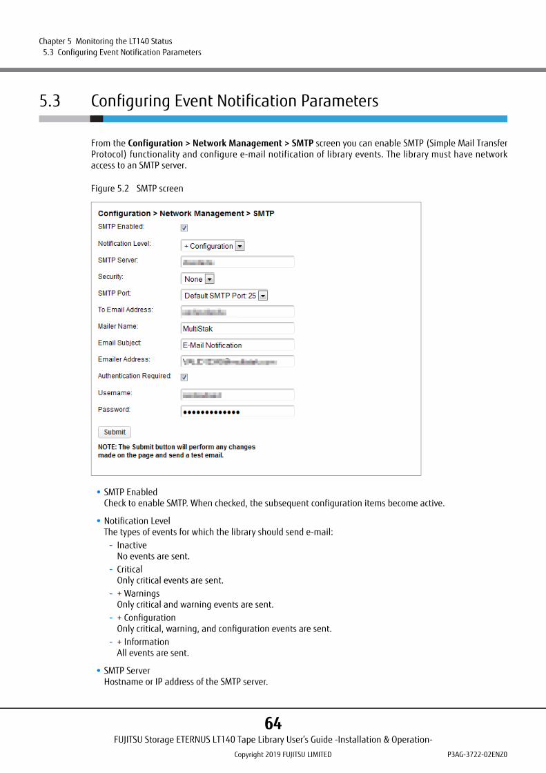
Chapter 5 Monitoring the LT140 Status 5.3 Configuring Event Notification Parameters
5.3 Configuring Event Notification Parameters
From the Configuration > Network Management > SMTP screen you can enable SMTP (Simple Mail TransferProtocol) functionality and configure e-mail notification of library events. The library must have networkaccess to an SMTP server.
Figure 5.2 SMTP screen
• SMTP EnabledCheck to enable SMTP. When checked, the subsequent configuration items become active.
• Notification LevelThe types of events for which the library should send e-mail:
- InactiveNo events are sent.
- CriticalOnly critical events are sent.
- + WarningsOnly critical and warning events are sent.
- + ConfigurationOnly critical, warning, and configuration events are sent.
- + InformationAll events are sent.
• SMTP ServerHostname or IP address of the SMTP server.
FUJITSU Storage ETERNUS LT140 Tape Library User’s Guide -Installation & Operation-
Copyright 2019 FUJITSU LIMITED P3AG-3722-02ENZ0
64

Chapter 5 Monitoring the LT140 Status 5.3 Configuring Event Notification Parameters
• SecuritySecurity protocol for accessing the SMTP server:
- None- SSL- TLS
• SMTP PortSMTP server port. The default port for the selected protocol will be selected. You can choose one of thedefault ports or configure a custom port.
• To Email AddressThe address that receives the reported events (for example [email protected]). Only oneemail address can be configured.
• Mailer NameName of the sender of the e-mail
• Email SubjectSubject line for the e-mail message
• Emailer AddressThe reply address used for e-mail messages
• Authentication RequiredWhen checked, a username and password are required to access the SMTP server.
• UsernameUser account for logging into the SMTP server when authentication is required.
• PasswordPassword associated with the Username when authentication is required.
FUJITSU Storage ETERNUS LT140 Tape Library User’s Guide -Installation & Operation-
Copyright 2019 FUJITSU LIMITED P3AG-3722-02ENZ0
65

Chapter 5 Monitoring the LT140 Status 5.4 Fault Monitoring (SNMP Report Function)
5.4 Fault Monitoring (SNMP Report Function)
The SNMP report function can be used to link the LT140 to a hardware management system that is connectedto a network.The SNMP report function uses the SNMP protocol to transmit device information obtained via MIB and errorinformation obtained via TRAP from the SNMP agent incorporated into the LT140 to the managementsoftware. This enables centralized management of the LT140 at one location, as is the case with othernetwork devices.For details on the SNMP TRAP list, refer to "Appendix A Event List" in "FUJITSU Storage ETERNUS LT140 TapeLibrary Overview".The LT140 supports SNMP v1, v2, and v3.
Figure 5.3 SNMP function
Settings related to the SNMP agent can be made from the remote panel.
Download the LT140 MIB file from the following website.https://www.fujitsu.com/global/support/products/computing/storage/download/index.html#id_lt
Monitoringscreen
Management server
LAN (SNMP)
MIB / TRAPcommunication
SNMP agent
LT140
Errorinformation
Deviceinformation
FUJITSU Storage ETERNUS LT140 Tape Library User’s Guide -Installation & Operation-
Copyright 2019 FUJITSU LIMITED P3AG-3722-02ENZ0
66

Chapter 6
Function Expansion Option
This chapter explains product options that can be added as required after system operation starts.
6.1 Expandable Components
Configuration of the Base Module (LT14AB) components and the expandable configurations are shownbelow.
Table 6.1 Component Configurations (Base Module / Expansion Module)
Maximum number of
stored cartridges
Number of Us
Number of tape drives
Base Module
(LT14AB)
Slot expansion
license (LT14AZ03)
(*1)
ExpansionModule
(LT14AZ40)
Tape drive (*2)
Power (LT14AZ06)
With / without power
redundancy
Power cable (*3)
20 3 1 to 3 1 0 0 1 to 3 0 / 1 1 / 2
40 3 1 to 3 1 1 0 1 to 3 0 / 1 1 / 2
80 61 to 3
1 1 11 to 3 0 / 1 1 / 2
4 to 6 4 to 6 1 / 3 2 / 4
120 9
1 to 3
1 1 2
1 to 3 0 / 1 1 / 2
4 to 6 4 to 6 1 / 3 2 / 4
7 to 9 7 to 9 2 / 5 3 / 6
160 12
1 to 3
1 1 3
1 to 3 0 / 1 1 / 2
4 to 6 4 to 6 1 / 3 2 / 4
7 to 9 7 to 9 2 / 5 3 / 6
10 to 12 10 to 12 3 / 7 4 / 8
200 15
1 to 3
1 1 4
1 to 3 0 / 1 1 / 2
4 to 6 4 to 6 1 / 3 2 / 4
7 to 9 7 to 9 2 / 5 3 / 6
10 to 12 10 to 12 3 / 7 4 / 8
13 to 15 13 to 15 4 / 9 5 / 10
240 18
1 to 3
1 1 5
1 to 3 0 / 1 1 / 2
4 to 6 4 to 6 1 / 3 2 / 4
7 to 9 7 to 9 2 / 5 3 / 6
10 to 12 10 to 12 3 / 7 4 / 8
13 to 15 13 to 15 4 / 9 5 / 10
16 to 18 16 to 18 5 / 11 6 / 12
FUJITSU Storage ETERNUS LT140 Tape Library User’s Guide -Installation & Operation-
Copyright 2019 FUJITSU LIMITED P3AG-3722-02ENZ0
67

Chapter 6 Function Expansion Option 6.1 Expandable Components
*1: This is required when the Expansion Module is used.*2: Select from LT14ASK, LT14AFK, LT14ASM, LT14AFM,LT14ASN or LT14AFN.*3: Select the number of LT14AZ06 plus one of the following: LTCBP05, LTCBP10, LTCBP15, LTCBP30, LTCBPN30 or
LTCBPN40.
280 21
1 to 3
1 1 6
1 to 3 0 / 1 1 / 2
4 to 6 4 to 6 1 / 3 2 / 4
7 to 9 7 to 9 2 / 5 3 / 6
10 to 12 10 to 12 3 / 7 4 / 8
13 to 15 13 to 15 4 / 9 5 / 10
16 to 18 16 to 18 5 / 11 6 / 12
19 to 21 19 to 21 6 / 13 7 / 14
Each option name may be suffixed with an "E" (for factory installed options) or an "L" (for field upgrades). For details on the model numbers, refer to "FUJITSU Storage ETERNUS LT140 Product List".
Maximum number of
stored cartridges
Number of Us
Number of tape drives
Base Module
(LT14AB)
Slot expansion
license (LT14AZ03)
(*1)
ExpansionModule
(LT14AZ40)
Tape drive (*2)
Power (LT14AZ06)
With / without power
redundancy
Power cable (*3)
FUJITSU Storage ETERNUS LT140 Tape Library User’s Guide -Installation & Operation-
Copyright 2019 FUJITSU LIMITED P3AG-3722-02ENZ0
68

Chapter 6 Function Expansion Option 6.2 License Partitioning Option (Logical Library Function)
6.2 License Partitioning Option (Logical Library Function)
A logical library is a function that logically partitions the robots, slots, and tape drives of a tape library andshows it as having up to 20 tape libraries. By using the logical library, a single LT140 can be physically sharedfrom different platforms and backup software.
For the LT140, a single tape library can be seen as having up to 21 tape libraries.
Figure 6.1 Direct connection (FC-AL connection, a multiple server connection, a shared library, and tape drives that are not shared)
Libraries that are on physical partitions are hereinafter called "physical libraries" and libraries that are onlogical partitions are hereinafter called "logical libraries".
To use the logical library function, a license for the License Partitioning Option is necessary.
Tape drive #0
Tape drive #1
Tape drive #2
LT140
Controller
FC cable
Server A
Backup software
HBA #1
HBA #0
Server B
Backup software
HBA #0
FUJITSU Storage ETERNUS LT140 Tape Library User’s Guide -Installation & Operation-
Copyright 2019 FUJITSU LIMITED P3AG-3722-02ENZ0
69

Chapter 6 Function Expansion Option 6.2 License Partitioning Option (Logical Library Function)
6.2.1 Function Overview
License Partitioning Option is valid for several UNIX / PC servers to use the Library as a shared device.As a result, decreasing the installation space, uniform management of the tapes, and operation costreduction can be achieved.
6.2.2 Hardware Configuration
This function logically partitions the slots, tape drives, mail slots to be seen as having multiple tape libraries.
■ Number of Logical Libraries
By using the License Partitioning Option, a single tape library can be seen as having up to 21 logical libraries.
■ Assigning Slots
Five slots are assigned to each partition.The following two methods are available for assigning slots.
• Basic Partition WizardIf you specify the number of partitions, the wizard removes the current partition configuration and assignsthe tape drives and storage slots as evenly as possible to the partitions.
• Expert Partition WizardYou can add or remove partitions from the current partition configuration. Use the Expert Partition Wizardto adjust resource (slots and tape drives) assignments for existing partitions or those created with theBasic Partition Wizard.
Refer to "6.2.3 Designing Logical Libraries" (page 73) for details about operations.
• Take special care when changing configurations after logical libraries are created because removing tape cartridges and changing backup software definitions may be required.
• If the logical library design (such as the number of slots) is changed, the backup software license may be affected. Refer to handbooks from each ISV before changing.
• To use the logical libraries, an additional option is necessary.• Make sure to design the logical library configuration before creating logical libraries.
CAUTIONDo Not
MalfunctionAfter defining the LT140 configuration in the backup software, the logical library configuration must not be changed. Changing the configuration may cause unexpected behavior of the backup software.
FUJITSU Storage ETERNUS LT140 Tape Library User’s Guide -Installation & Operation-
Copyright 2019 FUJITSU LIMITED P3AG-3722-02ENZ0
70
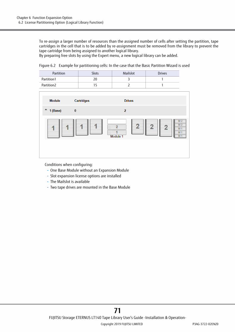
Chapter 6 Function Expansion Option 6.2 License Partitioning Option (Logical Library Function)
To re-assign a larger number of resources than the assigned number of cells after setting the partition, tapecartridges in the cell that is to be added by re-assignment must be removed from the library to prevent thetape cartridge from being assigned to another logical library.By preparing free slots by using the Expert menu, a new logical library can be added.
Figure 6.2 Example for partitioning cells: In the case that the Basic Partition Wizard is used
Conditions when configuring:- One Base Module without an Expansion Module- Slot expansion license options are installed- The Mailslot is available- Two tape drives are mounted in the Base Module
Partition Slots Mailslot Drives
Partition1 20 3 1
Partition2 15 2 1
FUJITSU Storage ETERNUS LT140 Tape Library User’s Guide -Installation & Operation-
Copyright 2019 FUJITSU LIMITED P3AG-3722-02ENZ0
71
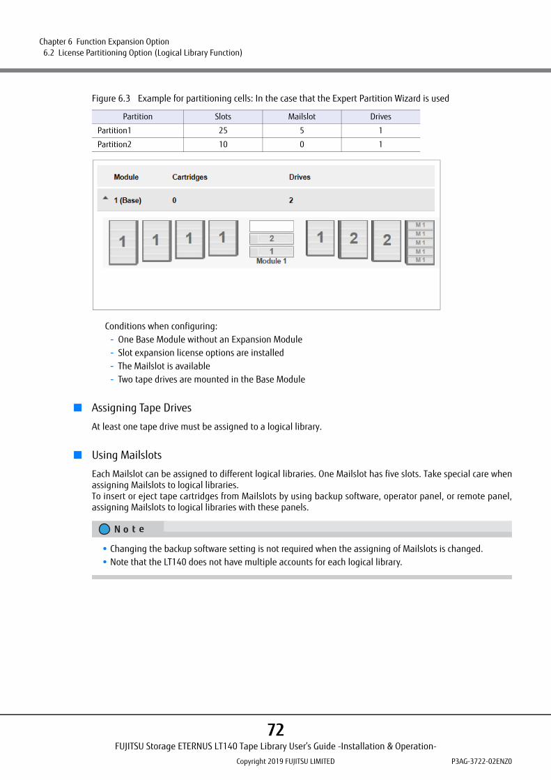
Chapter 6 Function Expansion Option 6.2 License Partitioning Option (Logical Library Function)
Figure 6.3 Example for partitioning cells: In the case that the Expert Partition Wizard is used
Conditions when configuring:- One Base Module without an Expansion Module- Slot expansion license options are installed- The Mailslot is available- Two tape drives are mounted in the Base Module
■ Assigning Tape Drives
At least one tape drive must be assigned to a logical library.
■ Using Mailslots
Each Mailslot can be assigned to different logical libraries. One Mailslot has five slots. Take special care whenassigning Mailslots to logical libraries.To insert or eject tape cartridges from Mailslots by using backup software, operator panel, or remote panel,assigning Mailslots to logical libraries with these panels.
Partition Slots Mailslot Drives
Partition1 25 5 1
Partition2 10 0 1
• Changing the backup software setting is not required when the assigning of Mailslots is changed.• Note that the LT140 does not have multiple accounts for each logical library.
FUJITSU Storage ETERNUS LT140 Tape Library User’s Guide -Installation & Operation-
Copyright 2019 FUJITSU LIMITED P3AG-3722-02ENZ0
72
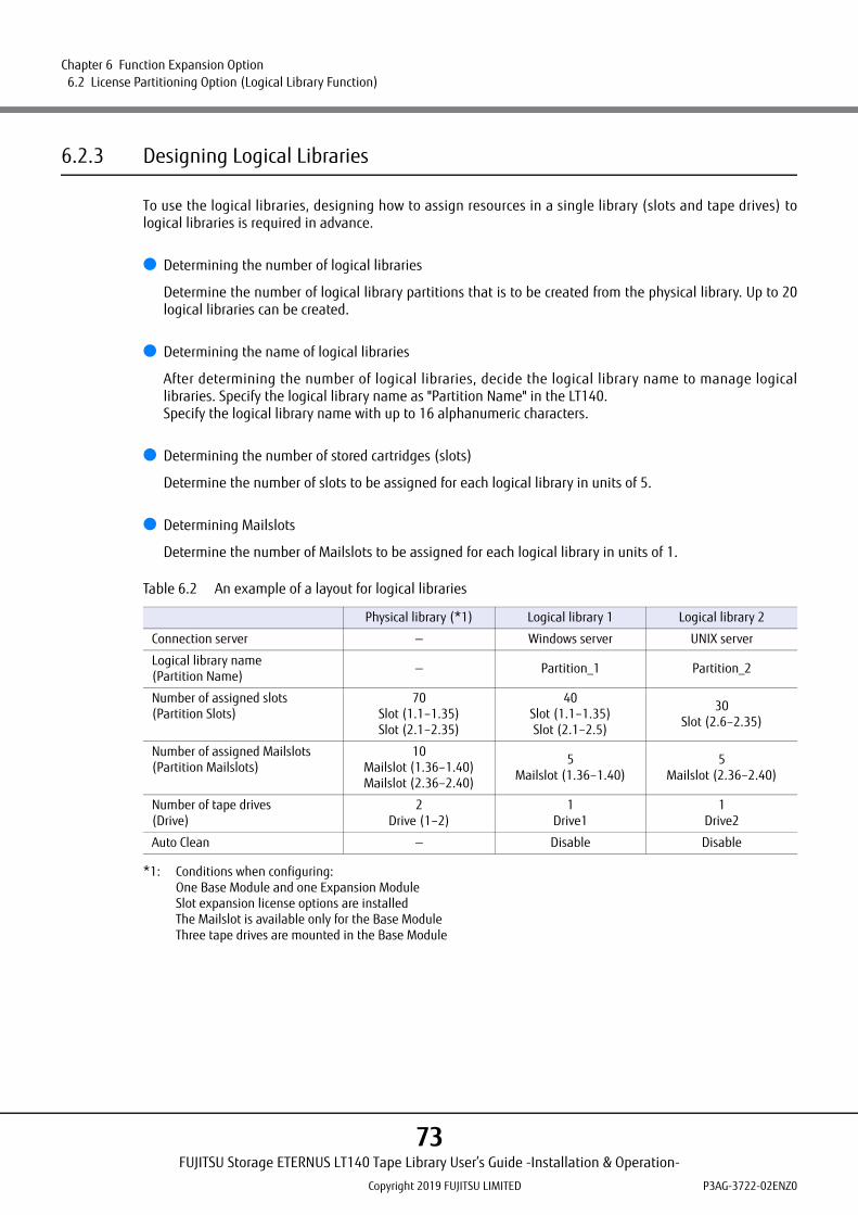
Chapter 6 Function Expansion Option 6.2 License Partitioning Option (Logical Library Function)
6.2.3 Designing Logical Libraries
To use the logical libraries, designing how to assign resources in a single library (slots and tape drives) tological libraries is required in advance.
● Determining the number of logical libraries
Determine the number of logical library partitions that is to be created from the physical library. Up to 20logical libraries can be created.
● Determining the name of logical libraries
After determining the number of logical libraries, decide the logical library name to manage logicallibraries. Specify the logical library name as "Partition Name" in the LT140.Specify the logical library name with up to 16 alphanumeric characters.
● Determining the number of stored cartridges (slots)
Determine the number of slots to be assigned for each logical library in units of 5.
● Determining Mailslots
Determine the number of Mailslots to be assigned for each logical library in units of 1.
Table 6.2 An example of a layout for logical libraries
*1: Conditions when configuring:One Base Module and one Expansion ModuleSlot expansion license options are installedThe Mailslot is available only for the Base ModuleThree tape drives are mounted in the Base Module
Physical library (*1) Logical library 1 Logical library 2
Connection server — Windows server UNIX server
Logical library name(Partition Name)
— Partition_1 Partition_2
Number of assigned slots(Partition Slots)
70Slot (1.1–1.35)Slot (2.1–2.35)
40Slot (1.1–1.35)Slot (2.1–2.5)
30Slot (2.6–2.35)
Number of assigned Mailslots(Partition Mailslots)
10Mailslot (1.36–1.40)Mailslot (2.36–2.40)
5Mailslot (1.36–1.40)
5Mailslot (2.36–2.40)
Number of tape drives(Drive)
2Drive (1–2)
1Drive1
1Drive2
Auto Clean — Disable Disable
FUJITSU Storage ETERNUS LT140 Tape Library User’s Guide -Installation & Operation-
Copyright 2019 FUJITSU LIMITED P3AG-3722-02ENZ0
73

Chapter 6 Function Expansion Option 6.2 License Partitioning Option (Logical Library Function)
6.2.4 Configuring Logical Libraries
After designing of the logical library completes, actually create the logical library.
6.2.4.1 Configuring Library Partitions
This operation is performed with the remote panel.
The LT140 has less-restricted adaptable partitioning methods.
• Basic Partition WizardIf you specify the number of partitions, the wizard removes the current partition configuration and assignsthe tape drives and storage slots as evenly as possible to the partitions. Any extra tape drives or slots areassigned to the first partition.
• Expert Partition WizardYou can add or remove partitions from the current partition configuration and then edit each partitionconfiguration to add or remove library resources.Use the Expert Partition Wizard to configure partitions that will have different resources or to adjustresource assignments for existing partitions or those created with the Basic Partition Wizard. Note that theauto tape drive cleaning function on each partition must be disabled.
For details about the operator panel and the remote panel, refer to "3.4.13 Configuring Library Partitions" in"Fujitsu Storage ETERNUS LT140 Tape Library User's Guide -Panel Operation-".
FUJITSU Storage ETERNUS LT140 Tape Library User’s Guide -Installation & Operation-
Copyright 2019 FUJITSU LIMITED P3AG-3722-02ENZ0
74

Chapter 6 Function Expansion Option 6.2 License Partitioning Option (Logical Library Function)
6.2.4.2 Using the Basic Partition Wizard
Procedure
1 Click Configuration > Partition > Basic Wizard.The Information screen displays the existing partitions, which will be deleted by the wizard.
2 Click Proceed.
FUJITSU Storage ETERNUS LT140 Tape Library User’s Guide -Installation & Operation-
Copyright 2019 FUJITSU LIMITED P3AG-3722-02ENZ0
75

Chapter 6 Function Expansion Option 6.2 License Partitioning Option (Logical Library Function)
3 Click Next.The Create Partition Scheme screen displays the number of slots, Mailslots, tape drives, and maximumavailable partitions for the library.
4 Enter the following items for "Partition Settings" and click Next.
• Partition Count (max. 21)Select the number of partitions.
• Barcode Label Length Reported To HostSelect the number of barcode characters reported to the host application.
• Barcode Label Alignment Reported To HostSelect whether to report the barcode characters from the left or right end of the barcode label to the host application.
• Auto CleanSet auto-cleaning to enable or disable.
If you want to enable or disable the Mailslots, cancel the wizard and update the Mailslot configuration before configuring partitioning.
FUJITSU Storage ETERNUS LT140 Tape Library User’s Guide -Installation & Operation-
Copyright 2019 FUJITSU LIMITED P3AG-3722-02ENZ0
76
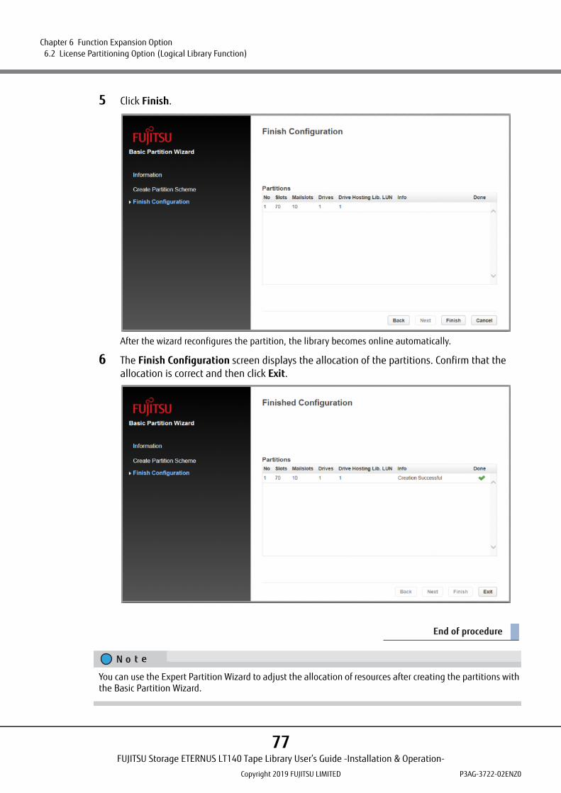
Chapter 6 Function Expansion Option 6.2 License Partitioning Option (Logical Library Function)
5 Click Finish.
After the wizard reconfigures the partition, the library becomes online automatically.
6 The Finish Configuration screen displays the allocation of the partitions. Confirm that the allocation is correct and then click Exit.
End of procedure
You can use the Expert Partition Wizard to adjust the allocation of resources after creating the partitions with the Basic Partition Wizard.
FUJITSU Storage ETERNUS LT140 Tape Library User’s Guide -Installation & Operation-
Copyright 2019 FUJITSU LIMITED P3AG-3722-02ENZ0
77
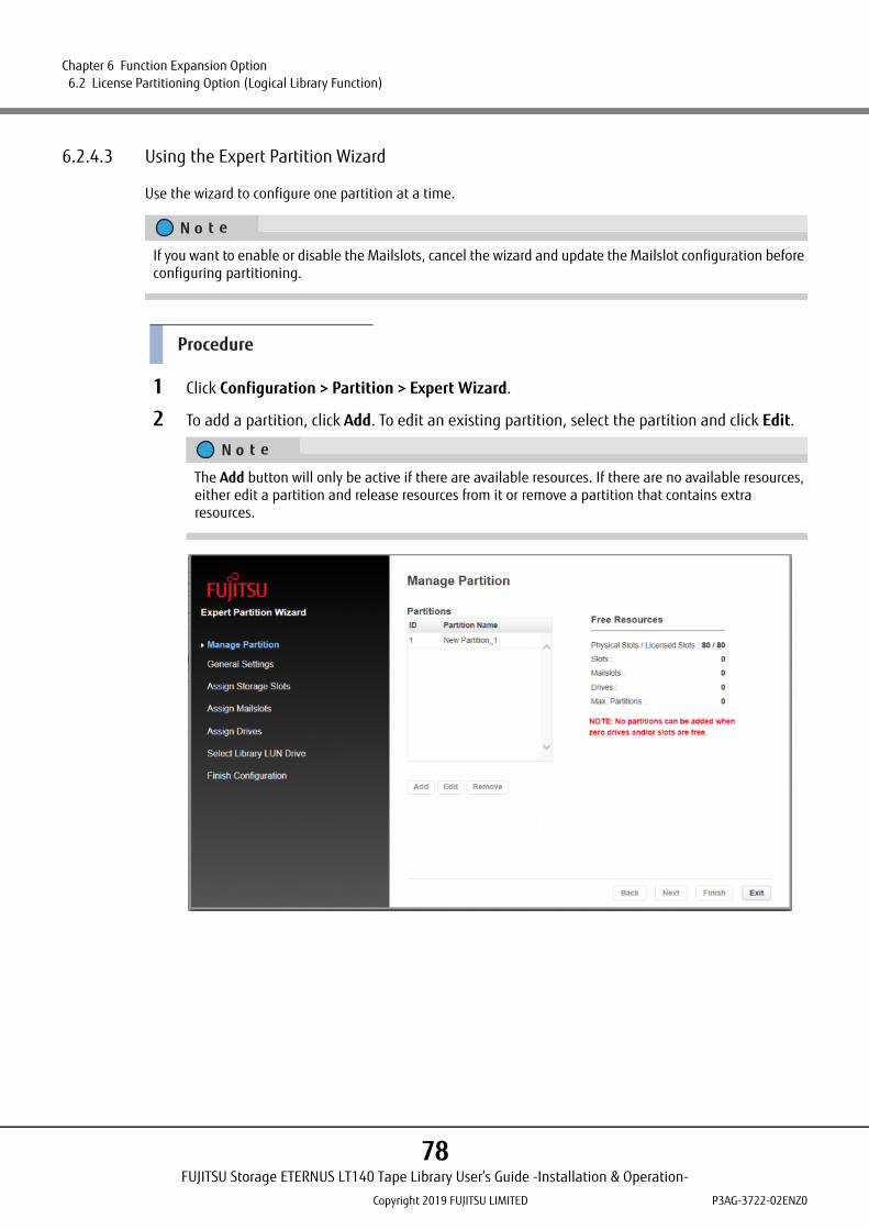
Chapter 6 Function Expansion Option 6.2 License Partitioning Option (Logical Library Function)
6.2.4.3 Using the Expert Partition Wizard
Use the wizard to configure one partition at a time.
Procedure
1 Click Configuration > Partition > Expert Wizard.
2 To add a partition, click Add. To edit an existing partition, select the partition and click Edit.
If you want to enable or disable the Mailslots, cancel the wizard and update the Mailslot configuration before configuring partitioning.
The Add button will only be active if there are available resources. If there are no available resources, either edit a partition and release resources from it or remove a partition that contains extra resources.
FUJITSU Storage ETERNUS LT140 Tape Library User’s Guide -Installation & Operation-
Copyright 2019 FUJITSU LIMITED P3AG-3722-02ENZ0
78

Chapter 6 Function Expansion Option 6.2 License Partitioning Option (Logical Library Function)
3 Click Next.The General Settings screen appears.
4 Enter the following items and click Next.
• Partition NameEnter a partition name
• Barcode Label Length Reported To HostSelect the number of barcode characters reported to the host application. This option provides interchange compatibility with libraries with more limited barcode reading capabilities. The maximum length is 15 and the default is 8. This configuration will apply to all partitions.
• Barcode Label Alignment Reported To HostSelect whether to report the barcode characters from the left or right end of the barcode label to the host application. For example, when reporting only six characters of the barcode label "12345678", if alignment is left, the device will report 123456. If alignment is right, the device will report 345678. The default is left.
• Encryption ModeSelect an encryption method to use for the partitions.
• Auto CleanSet auto-cleaning to enable or disable. If the backup software is used, the auto cleaning function must be disabled (default setting).If the auto-cleaning function is enabled, conflicts with the cleaning function of the backup software may lead to errors.If operations are performed with the LTFS option, the auto cleaning function can be enabled. For details, refer to "3.7 Cleaning the Tape Drive" in "FUJITSU Storage ETERNUS LT series Tape Libraries LTFS Option User’s Guide".
The industry standard length for LTO barcode labels is eight characters. Barcode labels longer than eight characters might be scanned incorrectly, particularly if they are not high quality labels.
FUJITSU Storage ETERNUS LT140 Tape Library User’s Guide -Installation & Operation-
Copyright 2019 FUJITSU LIMITED P3AG-3722-02ENZ0
79

Chapter 6 Function Expansion Option 6.2 License Partitioning Option (Logical Library Function)
• LTO7+ Multi-initiator SCSI Conflict DetectionDo not use this item. Make sure to leave the LTO7+ Multi-initiator SCSI Conflict Detection checkbox unchecked.
5 Click Next.
6 In the Assign Storage Slots screen, use the >> and << buttons to assign slots to the partition that is currently being edited and then click Next.
"Available Slots" indicates the remaining slots that can be assigned and "Partition Slots" indicates the slots that are to be assigned to the partition that is currently being edited.
FUJITSU Storage ETERNUS LT140 Tape Library User’s Guide -Installation & Operation-
Copyright 2019 FUJITSU LIMITED P3AG-3722-02ENZ0
80

Chapter 6 Function Expansion Option 6.2 License Partitioning Option (Logical Library Function)
7 In the Assign Mail Slots screen, use the >> and << buttons to assign Mailslots to the partition that is currently being edited and then click Next.Individual Mailslot elements cannot be shared between partitions. Importing or exporting cartridges ina partition without an assigned Mailslot will require magazine access. Opening a magazine takes thelibrary offline.
"Available Mailslots" indicates the remaining Mailslots that can be assigned and "Partition Maillots" indicates the Mailslots that are to be assigned to the partition that is currently being edited.
FUJITSU Storage ETERNUS LT140 Tape Library User’s Guide -Installation & Operation-
Copyright 2019 FUJITSU LIMITED P3AG-3722-02ENZ0
81

Chapter 6 Function Expansion Option 6.2 License Partitioning Option (Logical Library Function)
8 In the Assign Drives screen, use the >> and << buttons to assign tape drives to the partition that is currently being edited and then click Next.
9 Select a tape drive to use for the SCSI communication to the host and then click Next.The lowest numbered tape drive in the partition is the default.
"Available Drives" indicates the remaining tape drives that can be assigned and "Partition Drives" indi-cates the tape drives that are to be assigned to the tape drive that is currently being edited.
FUJITSU Storage ETERNUS LT140 Tape Library User’s Guide -Installation & Operation-
Copyright 2019 FUJITSU LIMITED P3AG-3722-02ENZ0
82

Chapter 6 Function Expansion Option 6.2 License Partitioning Option (Logical Library Function)
10 The Finish Configuration screen displays the partition allocation and then click Finish.
After the wizard reconfigures the partition, the library automatically becomes online.
11 Click Close.
12 Click Exit.
End of procedure
FUJITSU Storage ETERNUS LT140 Tape Library User’s Guide -Installation & Operation-
Copyright 2019 FUJITSU LIMITED P3AG-3722-02ENZ0
83

Chapter 6 Function Expansion Option 6.3 Key Management Function Option
6.3 Key Management Function Option
This section explains the Key Management Function Option.
6.3.1 Overview
The Key Management Function Option allows the use of the encryption function provided by LTO Ultrium tapedrives to manage encryption keys on the tape library.
Figure 6.4 shows the concept of this option.
Figure 6.4 Key Management Function Option
The Key Management Function Option applies the encryption settings from the remote panel to the tapelibrary and assigns one key called the master key. The encryption key that is automatically generated for eachdata cartridge by the tape library is based on the master key, and this information is stored in a database inthe tape library.During a data backup from a backup server, the tape library automatically assigns an encryption key to thespecified data cartridge, encrypts the data (plain text), and saves the data. The encryption process isperformed transparently during this time.
Tape library
Encryption key
Encryption setting(When the encryptionsettings are applied)
Backup server
Master key
Key managementdatabase
Plain text
Encrypted data
LTO Ultriumtape drive
Remote panel
LT140
FUJITSU Storage ETERNUS LT140 Tape Library User’s Guide -Installation & Operation-
Copyright 2019 FUJITSU LIMITED P3AG-3722-02ENZ0
84
Chapter 6 Function Expansion Option 6.3 Key Management Function Option
6.3.2 Features of the Key Management Function Option
This option has the following features:
• The Key Management Function Option can be used independently of the OS and backup software because the LT140 automatically performs encryption operations. This allows a secure backup system to be easily constructed (*1).
• Encryption keys are assigned to tape libraries from the Web browser terminal. This means that the tape library administrators can maintain security without intervention by backup operators.
• When a single key (master key) is assigned to a tape library, an encryption key is automatically assigned to each data cartridge within the tape library. This means that the administrator does not need to manage the encryption keys of each data cartridge.
• The ETERNUS LT140, LT220, LT230, LT250, LT260, LT270, and LT270 S2 in the ETERNUS tape library series have compatible master keys (*2), so setting a common master key for these tape libraries facilitates data sharing or data migration of encrypted tape cartridge data between the tape libraries.
• To share data among multiple tape libraries, Fujitsu recommends operation with a common master key. If a disaster occurs, however, it might be necessary to read data from a data cartridge stored at an external site using a tape library assigned a different master key. For this purpose, you can export encryption keys in advance using the encryption key export/import function.
*1: This encryption function cannot be used together with the encryption function of the backup software.*2: The ETERNUS LT20, LT20 S2, LT40, LT40 S2, LT60, LT60 S2, LT200, LT210 do not support the encryption key
management function. Note that sales of the ETERNUS LT220, LT230, LT250, and LT270 tape libraries have beendiscontinued.
The following tape drives and tape cartridges are required to use the Key Management Function Option:• LTO Ultrium 6 (G6) or later tape drives.• LTO Ultrium 4 (G4) or later tape cartridges
For other required optional products, refer to "FUJITSU Storage ETERNUS LT140 Tape Library Product List". For more details about tape cartridges, refer to "A.1 Ultrium Tape Cartridge" (page 109).
To use the key management function, purchasing the Key Management Function Option is required.
FUJITSU Storage ETERNUS LT140 Tape Library User’s Guide -Installation & Operation-
Copyright 2019 FUJITSU LIMITED P3AG-3722-02ENZ0
85

Chapter 6 Function Expansion Option 6.3 Key Management Function Option
6.3.3 Types of Key
There are two types of encryption keys; a master key that is required for each LT140 and an encryption keythat is assigned for each tape cartridge in the tape library.
■ Master key
The master key is a key assigned to each tape library.You must assign a master key before using this option.The functions of a master key are listed below.
• The master key is used to automatically create encryption keys for individual data cartridges (*1).• The same master key can be assigned to multiple tape libraries. A data cartridge that stores encrypted
data can be shared between multiple tape libraries by setting the same master key for these tape libraries.• The master key can be set by the administrator of the tape library.• For logical library configurations, a master key can be assigned to each logical library.
*1: Since automatically generated master keys are managed by the tape library alone, their values are not visible tousers.
The two methods of creating a master key are as follows: automatic generation by the LT140 and creation bythe user using arbitrary characters.If you choose automatic generation, a master key is created based on information that is specific to the tapelibrary. The same master key as already assigned to another tape library is never created. Master keys, oncecreated, cannot be restored even by the manufacturer or maintenance engineer.Although the master key is stored redundantly in the database of the tape library, it may be lost in the rareevent that the tape library fails. Because the encrypted data becomes unreadable in these cases, be sure todownload the master key (as a binary file) and keep it in a safe place.
■ Encryption key
An encryption key is a key uniquely assigned to each data cartridge.Encryption keys are automatically generated based on the master key and the data that is unique to eachdata cartridge. This assures that different data cartridges never have the same encryption key.If the same master key and the same tape cartridge are used in different tape libraries, the tape libraries willgenerate the same encryption key for the cartridge.Each data cartridge can be assigned only one encryption key.In normal operation, the tape library performs encryption key operations automatically, without requiring anyoperations by the user.
The encryption key export/import function can be used to export or import only an encryption key (a password and encrypted binary file) for data sharing between tape libraries with different master keys. However, note that if the encryption key is lost, the data can no longer be restored.To share data among multiple tape libraries, Fujitsu recommends operation with a common master key.
FUJITSU Storage ETERNUS LT140 Tape Library User’s Guide -Installation & Operation-
Copyright 2019 FUJITSU LIMITED P3AG-3722-02ENZ0
86

Chapter 6 Function Expansion Option 6.3 Key Management Function Option
Figure 6.5 Concept of automatic encryption key generation
6.3.4 Operational Examples
Data encryption by the Key Management Function Option does not affect normal operation.This section provides some examples of using the Key Management Function Option, including storage of anencrypted data cartridge at another site and data sharing among multiple tape libraries.
■ Data sharing between centers
Assigning the same master key for multiple tape libraries installed at the same center or separate centersenables these tape libraries to share data cartridges with encryption keys hidden from view.
Figure 6.6 Sharing data cartridges using a master key
Tape cartridge
Operator
Setting
Non-encryption
Database for key management
Encryption key 0 Encryption 0
Encryption 1
Encryption 2
Specific information of the tape cartridge
Encryption key 1
Encryption key 2
Automatic generation
Master key
Primary-site
Master key A
Backup-center
Transported only the cartridges
Master key A
FUJITSU Storage ETERNUS LT140 Tape Library User’s Guide -Installation & Operation-
Copyright 2019 FUJITSU LIMITED P3AG-3722-02ENZ0
87

Chapter 6 Function Expansion Option 6.3 Key Management Function Option
■ Encryption of data on a data cartridges stored at an external location
For disaster recovery, encrypted data cartridges can be stored at an external location, such as an externalwarehouse, and, when needed, brought back to read the data on them. Even if a data cartridge in storage islost or stolen, the encryption can prevent data leakage.Once a data cartridge in storage is inserted into its original tape library or one with the same master key, thedata can be read from the tape library without setting the key again.
Figure 6.7 External storage of data cartridges
Once encryption keys are exported, even if the tape library becomes unavailable such as in the event of a disaster, data on the data cartridge can be read by importing the encryption key to a tape library with a dif-ferent master key.
Secondary-site
Master key A
Encryption key
Primary-site
Encryption key
Master key A
FUJITSU Storage ETERNUS LT140 Tape Library User’s Guide -Installation & Operation-
Copyright 2019 FUJITSU LIMITED P3AG-3722-02ENZ0
88

Chapter 6 Function Expansion Option 6.3 Key Management Function Option
■ Encryption key setting for each logical library
When using the logical library configuration, individual master key assignments and encryption/non-encryption can be specified for each logical library.
Figure 6.8 Encryption key setting for each logical library
Master key
: Encryption
: Non-Encryption
Lib #3
Lib #2
Lib #1Master key
FUJITSU Storage ETERNUS LT140 Tape Library User’s Guide -Installation & Operation-
Copyright 2019 FUJITSU LIMITED P3AG-3722-02ENZ0
89

Chapter 6 Function Expansion Option 6.3 Key Management Function Option
■ Interoperation among LT-series models
The ETERNUS LT140, LT220, LT230, LT250, LT260, LT270, and LT270 S2 tape libraries (LT-series) sharecompatible master keys and encryption keys, so keys and encrypted data cartridges can be shared among theLT-series tape libraries.Setting a common master key for these tape libraries facilitates data sharing or data migration between thetape libraries with the keys hidden from view.
Figure 6.9 Interoperation among LT-series models
6.3.5 Connectivity with Backup Software
On a system using the encryption key management function, Fujitsu recommends using verified backupsoftware.Make sure to disable the native encryption function of the backup software if a backup software that supportsthe tape drive encryption function of Ultrium 6 or later is used.
• The Key Management Function Option does not support interoperability with data cartridges encrypted by the encryption function of tape libraries, software, or other products manufactured by other companies.Refer to "Table A.3 Tape drive compatibility with data cartridges" (page 111) for details.
• Sales of the ETERNUS LT220, LT230, LT250, and LT270 tape libraries have been discontinued.
LT270 S2
LT260
LT140
FUJITSU Storage ETERNUS LT140 Tape Library User’s Guide -Installation & Operation-
Copyright 2019 FUJITSU LIMITED P3AG-3722-02ENZ0
90

Chapter 7
Troubleshooting
This chapter explains troubleshooting.
7.1 Fibre Channel Connection Problems
Use the Status> Drive Status screen to check the link connection for your tape drive.
■ If the screen shows Logged Out:
• Check that the Fibre speed is set to Automatic or that the correct Fibre speed is selected. If you are unsure of the speed of the HBA or switch that the tape drive is connected to, try Automatic.
• Check that the correct port type, fabric or loop, is selected. Loop requires additional configuration. If you are unsure of the correct port type, try Automatic.
■ If the screen shows No Link, the Speed Status is "-" and the Link LED on the back of the tape drive is off:
The speed is probably set incorrectly. Try setting the speed to Automatic.If there are still issues, change the port type to Auto Detect.
■ If the screen shows No Light:
• The cable is not plugged in correctly. Check that it is connected correctly to Port A of the tape drive.• The cable is damaged. FC cables are delicate. If the cable has been bent or twisted sharply, it might be
broken and must be replaced.
■ If the screen shows ALPA Conflict:
There might be a conflict with the ALPA address on Loop ports.Select Soft for the Loop mode to allow the system to select an available address each time the tape driveconnects to the FC fabric.If your server configuration does not support changing addresses, try using the Hard Auto-Select Option forthe Loop mode. This allows the system to select an available address when it first connects, and then retainthat address for future connections.
This library is designed to operate when installed in a rack using the rack rail kit. Operating the library without installing it in the rails, such as on a table or rack shelf, could result in library errors. Placing any weight on top of the library might also cause errors.
FUJITSU Storage ETERNUS LT140 Tape Library User’s Guide -Installation & Operation-
Copyright 2019 FUJITSU LIMITED P3AG-3722-02ENZ0
91
Chapter 7 Troubleshooting 7.2 Detection Problems after Installing a SAS Drive
7.2 Detection Problems after Installing a SAS Drive
Problems encountered after installation are often caused by improper SAS cable connections, applicationsoftware configuration errors, or an incorrectly configured operating system. If the application software oroperating system does not communicate with the library after installation, determine the extent of thedetection problem:
• Does the application software detect the tape drive?• Does the application software detect the library?• Does the operating system detect the tape drive?• Does the operating system detect the library?• Does the operating system detect the library, but list it as a generic device?
Based on the extent of the detection problem, check the following:
■ If neither the application software nor operating system detects the tape drive, or they do not detect both the tape drive and the library:
• Verify that all SAS cables are securely connected on both ends. If the mini-SAS connectors that connect to the tape drive and some HBAs will not plug in, check the key. The mini-SAS connector on the tape drive is keyed at location four, which is the standard location for end devices. If the connector on the cable is keyed in a different location, not only will the connector not plug in, but the cable probably will not work.
• Check the length and integrity of your SAS cabling. For reliable operation, do not use a SAS cable longer than six meters. Do not use a cable adapter or converters between the HBA and the library.
• Check the SAS connectors for damage or debris.• Verify that your HBA is supported by the host computer and qualified with the library.• Verify that your HBA has the latest firmware.
■ If the application software or operating system detects the tape drive, but not the library:
Verify that multiple LUN support is enabled on the HBA. The library uses two Logical Unit Numbers (LUNs) tocontrol the tape drive (LUN 0) and robotic (LUN 1). The library requires an HBA with multiple LUN support andmultiple LUN support must be enabled on the host computer. When multiple LUN support is not enabled, thehost computer can see the tape drive, but not the library.
■ If the application software or operating system does not detect any devices on the HBA:
• Verify that the SAS host adapter is installed correctly. Refer to the manual that came with your host adapter for installation and troubleshooting instructions. Pay particular attention to any steps describing configuration settings. Make sure that the host adapter is properly seated in the motherboard slot and the operating system correctly detects the host adapter.
• Verify that the proper device driver is installed for the SAS host adapter.
Many RAID or array controllers do not provide multiple LUN support.
FUJITSU Storage ETERNUS LT140 Tape Library User’s Guide -Installation & Operation-
Copyright 2019 FUJITSU LIMITED P3AG-3722-02ENZ0
92
Chapter 7 Troubleshooting 7.2 Detection Problems after Installing a SAS Drive
■ If the library is detected by the operating system, but not by the application software:
Refer to the documentation included with your backup application for instructions on how to verify properinstallation. Some backup software packages require an additional module to communicate with the robotics.
■ If the library is detected by the operating system, but is listed as an unknown or generic device:
• Make sure that the proper device driver, if applicable, is installed for the device. Check your software provider's website for the latest drivers and patches.
• If you continue to have problems with a SAS library, check the following:- Ensure that the library is compatible with the SAS host adapter and backup application you plan to use.- Verify that your HBA is supported by the host computer and qualified with the library.- Ensure you are using a compatible, high-quality cable.
Many backup applications use their own drivers. Before installing a driver, make sure it is not in conflict with the application software.
FUJITSU Storage ETERNUS LT140 Tape Library User’s Guide -Installation & Operation-
Copyright 2019 FUJITSU LIMITED P3AG-3722-02ENZ0
93
Chapter 7 Troubleshooting 7.3 Operation Problems
7.3 Operation Problems
This section describes problems that may occur during operation and how to resolve them.
7.3.1 Power Problems
■ Device does not power on.
Perform the following procedure:
Procedure
1 Check all power cord connections.
2 Check the LEDs on the power supplies.
3 Make sure the power button on the operator panel has been pressed, and the green Ready LED is lit.
4 Make sure the outlet has power.Try another working outlet.
5 Replace the power cord.
End of procedure
■ No message appears on the LCD screen.
Perform the following procedure:
Procedure
1 Check all power cord connections.
2 Check the LEDs on the power supplies.
3 Make sure the power button on the operator panel has been pressed, and the green Ready LED is lit.
4 Make sure the outlet has power.Try another working outlet.
End of procedure
FUJITSU Storage ETERNUS LT140 Tape Library User’s Guide -Installation & Operation-
Copyright 2019 FUJITSU LIMITED P3AG-3722-02ENZ0
94
Chapter 7 Troubleshooting 7.3 Operation Problems
7.3.2 Failure/Attention Indications Displayed on the Operator Panel
■ The operator panel displays "Err" or "Warn".
Check the event log detail by referring to "7.5 Checking Event Information" (page 102).
7.3.3 Tape Movement Problems
■ Tape stuck in drive.
Try the following steps, in this order, to remove the stuck tape.
The Ready light flashes while the tape rewinds. Wait for the tape to finish rewinding before attemptinganother operation.
Procedure
1 Attempt to unload the tape from your backup software.
2 Shut down the backup software and stop the operating system's removable storage services. From the Operation > Move Media screen, attempt to unload or move the tape to a slot.
3 Power down the library, disconnect the cable from the tape drive, power up the library, and wait until the tape drive is idle or ready. From the Operation > Move Media screen, attempt to unload or move the tape to a slot.
4 From the Operation > Force Drive Media Eject screen, attempt a force eject or emergency unload operation.
End of procedure
The tape drive must rewind the tape before ejecting it. This can take as long as five minutes, depending on how much tape must be rewound. Once the tape is rewound, the eject cycle will take fewer than 16 seconds.
Inspect the tape cartridge that was stuck. Damage or misplaced labels on the cartridge could have caused the load/unload failure. Discard any tape cartridge found to have issues.
FUJITSU Storage ETERNUS LT140 Tape Library User’s Guide -Installation & Operation-
Copyright 2019 FUJITSU LIMITED P3AG-3722-02ENZ0
95
Chapter 7 Troubleshooting 7.3 Operation Problems
■ Tape cannot be removed from slot.
If the operator panel or remote panel is still operational:
Procedure
1 Unlock the magazine from the Operation > Open Magazine screen and extend it to access the slot.
2 Grasp the cartridge and remove it from the slot.Some tapes need to be inserted and removed several times to condition them for free movement inand out of the magazine.
3 Check the barcode label and verity that it is secure to the cartridge.
4 Check the cartridge for damage.
5 Check the slot for damage.
End of procedure
■ Inserted tapes are not recognized.
If the slot expansion license is not installed, the tape cartridges in the slots of the left magazine are notrecognized. Use the slots (1.21 to 1.40) of the right magazine.If the number of slots that can be used is insufficient, consider the installation of the expansion license.
7.3.4 Media Problems
■ Cleaning or data cartridge incompatible with tape drive.
• Check the event log to see which cartridge is incompatible.• Make sure you are using data and cleaning cartridges that are compatible with the tape drive and model of
your device and that you are using the correct cartridge type for the operation. The device automatically unloads incompatible cartridges, the Attention LED flashes. Export the media.
■ Cannot write to or read from tape.
• Make sure that the cartridge is not a WORM cartridge that has already been used.• Make sure that the cartridge is write enabled (move the write-protect switch to the enabled position).• Make sure the data cartridge is compatible with the tape drive model. LTO tape drives can read data
cartridges from two generations back and write to data cartridges one generation back.• Make sure you are using an Ultrium cartridge that has not been degaussed. Do not degauss Ultrium
cartridges!• Make sure that the cartridge has not been exposed to harsh environmental or electrical conditions and is
not physically damaged in any way.• Many backup applications do not read or write to cartridges that were created using a different backup
application. In this case, you may have to perform an erase, format, or label operation on the cartridge.
FUJITSU Storage ETERNUS LT140 Tape Library User’s Guide -Installation & Operation-
Copyright 2019 FUJITSU LIMITED P3AG-3722-02ENZ0
96

Chapter 7 Troubleshooting 7.3 Operation Problems
• Make sure you understand any data protection or overwrite protection schemes that your backup application may be using, which could prevent you from writing to a given cartridge.
• Retry the operation with a different, known good tape.• Clean the tape drive from the Operation > Clean Drive screen.
7.3.5 Attention LED is Lit
■ Both the Attention and Cleaning LEDs are lit.
This is most likely caused by a dirty tape drive that cannot read a tape and marks the tape invalid.Log into the operator panel or remote panel and check the event log to see which tape drive has reported thatit needs cleaning. Clean the tape drive with an approved Ultrium cleaning cartridge.
■ A particular cartridge sets off the cleaning light.
Remove the cartridge from the library.
■ A cartridge recently imported from a different environment is causing issues.
Media that is moved from one environment to another can cause issues until it has acclimated to the newconditions. A cartridge should be acclimated for at least 24 hours before being used, particularly if it has beenstored at a substantially different temperature or level of humidity than the device.
■ The Attention LED is lit but the Cleaning LED is not lit after a cartridge load.
The library was unable to complete the requested operation with the selected tape cartridge.• Use only cartridges that are compatible with the tape drive type.• Use the correct type of cartridges for the operation. For example, use a cleaning cartridge for cleaning.• Make sure you are using an Universal cleaning cartridge.
■ The Cleaning LED is lit after using a cleaning cartridge.
The cleaning cartridge has expired. A cleaning cartridge will expire after approximately 50 cleaning cycles.
■ A particular cartridge sets off the Attention LED and possibly the Cleaning LED.
Retry the operation with a different cleaning cartridge.If the Attention LED is cleared and the tape drive has been cleaned, and then immediately re-displays eachtime a particular cartridge is reloaded, that cartridge should be suspected as being defective.
• If this occurs, export the cartridge and load a known good cartridge. In some cases, a cartridge can be worn out, have a defective Cartridge Memory, or have been formatted as a Firmware Upgrade Cartridge.
• Any cartridge that is suspected of being defective or contaminated should NOT be reused in any tape drive.• If the bad cartridge is a cleaning cartridge, it might be expired.
FUJITSU Storage ETERNUS LT140 Tape Library User’s Guide -Installation & Operation-
Copyright 2019 FUJITSU LIMITED P3AG-3722-02ENZ0
97
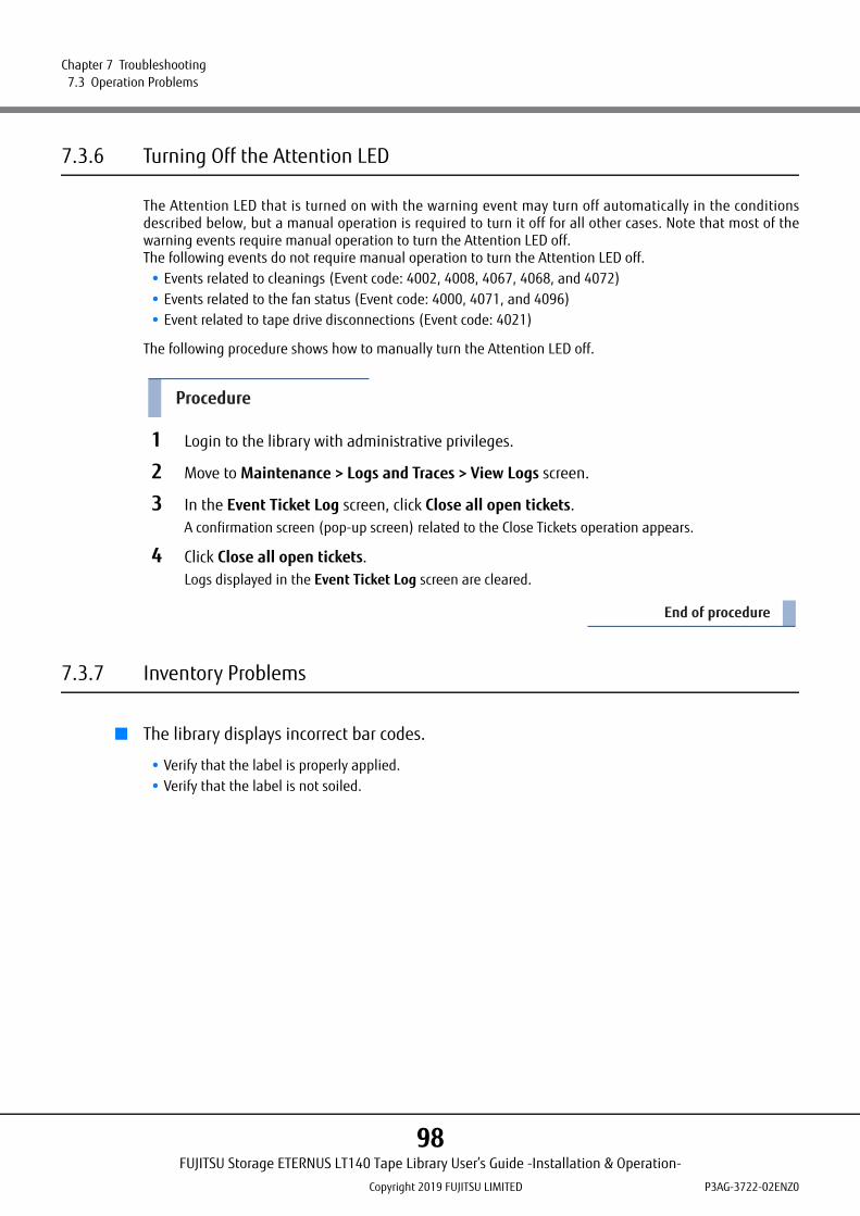
Chapter 7 Troubleshooting 7.3 Operation Problems
7.3.6 Turning Off the Attention LED
The Attention LED that is turned on with the warning event may turn off automatically in the conditionsdescribed below, but a manual operation is required to turn it off for all other cases. Note that most of thewarning events require manual operation to turn the Attention LED off.The following events do not require manual operation to turn the Attention LED off.
• Events related to cleanings (Event code: 4002, 4008, 4067, 4068, and 4072)• Events related to the fan status (Event code: 4000, 4071, and 4096)• Event related to tape drive disconnections (Event code: 4021)
The following procedure shows how to manually turn the Attention LED off.
Procedure
1 Login to the library with administrative privileges.
2 Move to Maintenance > Logs and Traces > View Logs screen.
3 In the Event Ticket Log screen, click Close all open tickets.A confirmation screen (pop-up screen) related to the Close Tickets operation appears.
4 Click Close all open tickets.Logs displayed in the Event Ticket Log screen are cleared.
End of procedure
7.3.7 Inventory Problems
■ The library displays incorrect bar codes.
• Verify that the label is properly applied.• Verify that the label is not soiled.
FUJITSU Storage ETERNUS LT140 Tape Library User’s Guide -Installation & Operation-
Copyright 2019 FUJITSU LIMITED P3AG-3722-02ENZ0
98
Chapter 7 Troubleshooting 7.3 Operation Problems
7.3.8 Remote Panel Network Connection Issues
■ Cannot connect to the remote panel.
• Verify that the Ethernet cable is connected to the Base Module’s library controller and to the LAN.• Verify that the link LED on the RJ45 (LAN) connector is lit when the device is powered up. If the LED is not
lit, the device is not communicating with the LAN. See your network administrator for help.• Verify that the device has been configured with a valid static network address or DHCP has been enabled
so the device can obtain a network address.If using DHCP, write down the device's network address from the operator panel login screen.If the device did not obtain a valid address via DHCP, verify that the DHCP server is up and the library hasnetwork access to it. If necessary, set a static network address instead.
• Enter the library's IP address into the address bar of a web browser connected to the same LAN as the device.If the remote panel web page does not display, ping the device's IP address.If the ping fails, verify that the device has a valid network address and that there are no firewalls or otherobstructions to network traffic between the computer with the web browser and the device. See yournetwork administrator for help.
7.3.9 Cleaning Problems
■ Cannot load the cleaning cartridge.
• Make sure you are using an Ultrium cleaning cartridge.• Make sure the cleaning cartridge has not expired. The cleaning cartridge will expire after approximately 50
cleaning cycles.• Power cycle the library.
FUJITSU Storage ETERNUS LT140 Tape Library User’s Guide -Installation & Operation-
Copyright 2019 FUJITSU LIMITED P3AG-3722-02ENZ0
99

Chapter 7 Troubleshooting 7.4 Performance Problems
7.4 Performance Problems
The process of backing up files involves many system components, from the files in the file system on the disk,through the backup server, and out to the library, all managed by software running on an operating system.The backup process can only run as fast as the slowest component in the system.Performance issues are solved by identifying and addressing performance limitations in your system. Refer tosections below for the following potential performance limitations:
• Average File Size• File Storage System• Connection from the Backup/Archive Host Server to the Disk Storage System• Backup/Archive Server• Backup/Archive Software and Method• Connection from the Archive/Backup Host Server to the Library• Media
7.4.1 Average File Size
The hard disk drive must seek to the position of a file before it can start reading. The more time the disks areseeking to files, the lower the performance. Therefore, if the average file size is small, the read performancewill be lower.To determine the average file size, divide the size of the backup by the number of files.If the average file size is small (64 KB or less), consider using a sequential, image, or block backup methodthat backs up the whole hard disk drive or LUN image instead of individual files. The trade off for using one ofthese methods is that you might only be able to restore the entire image instead of individual files.
7.4.2 File Storage System
The file storage system determines the organization of the files on the disks. Using RAID controllers to spreadfiles over multiple disks can improve performance because some disks can be seeking while others arereading. Storing files on a single non-RAID disk results in the slowest performance while storing files on ahigh-end Disk storage system results in the fastest performance.Converting standalone disks to RAID can improve performance.
File fragmentation will also cause excessive hard disk drive seeking, which lowers performance, so ensure that files are regularly defragmented.
FUJITSU Storage ETERNUS LT140 Tape Library User’s Guide -Installation & Operation-
Copyright 2019 FUJITSU LIMITED P3AG-3722-02ENZ0
100
Chapter 7 Troubleshooting 7.4 Performance Problems
7.4.3 Connection from the Backup/Archive Host Server to the Disk Storage System
The connection between the host server and the disks determines how much data can be transferred from thedisks to the host computer at a time. A connection with insufficient bandwidth cannot provide enough datafor the tape drives to write at full speed. For optimum performance, the storage subsystem must be able toprovide data at the tape drive's maximum transfer rate.Backup systems using a lower speed Ethernet network should use multiple network connections.
7.4.4 Backup/Archive Server
The backup server must have enough RAM and processor power to transfer the files from the disk to the tapedrive, in addition to running the backup or archive software and any other processes.Check the RAM and processor usage during a backup operation. If they are operating at capacity, adding RAMor processor capability can improve performance.
7.4.5 Backup/Archive Software and Method
Each backup method has its own impact on performance, depending on how well it can keep data streamingto the tape drive. In most cases, native applications don't have the features required to maximizeperformance for LTO tape drives. It is recommended to use a full-featured backup or archive application withthis library.File-by-file backup or archive methods provide the best restore performance if you only need to restoreindividual files. However, if the average file size is small, file-by-file methods will significantly reduceperformance.Disk image, flash, or sequential backup methods provide the fastest performance because they back up anentire disk, partition, or LUN, which minimizes disk seeking. The disadvantage is that backup and restoreoperations work on an entire disk, partition, or LUN. You might not be able to back up a subset of files orrestore a single file. If you can restore a single file, the restore process will be slow.
Database backup performance will vary based on the use model. To improve performance when backing updata from a database:
• Use specific backup agents for the database.• Use the latest versions of the databases.• Do not back up individual mailboxes.• Do not back up specific records or do a record-by-record backup.• Do not back up when the database is in heavy use.
7.4.6 Connection from the Archive/Backup Host Server to the Library
For the best performance, the connection from the host server to the library must have enough bandwidth toprovide enough data to keep the tape drive streaming. Current LTO tape drives take advantage of some of thefastest interfaces available so the type of interface used to connect the library to the host server is not likely tobe the cause of a performance issue. However, issues with cables and connectors can limit performance.Do not exceed recommended cable lengths.
FUJITSU Storage ETERNUS LT140 Tape Library User’s Guide -Installation & Operation-
Copyright 2019 FUJITSU LIMITED P3AG-3722-02ENZ0
101
Chapter 7 Troubleshooting 7.5 Checking Event Information
7.4.7 Media
The type and condition of the media also affect backup performance. For best performance, use media that isthe same LTO generation as the tape drives.
7.5 Checking Event Information
Event information can be checked from the operator panel or the remote panel.
• For the operator panelFrom the Maintenance > View Event Ticket Logs screen, event logs can be checked.Error and Warning level events can be checked from the remote panel.For details, refer to "2.6.2 Checking Event Logs" in "FUJITSU Storage ETERNUS LT140 Tape Library User'sGuide -Panel Operation-".
• For the remote panelFrom the Maintenance > Logs and Traces > View Logs screen, event logs can be checked.For details, refer to "3.5.2 Viewing Log Files" in "FUJITSU Storage ETERNUS LT140 Tape Library User's Guide -Panel Operation-".
FUJITSU Storage ETERNUS LT140 Tape Library User’s Guide -Installation & Operation-
Copyright 2019 FUJITSU LIMITED P3AG-3722-02ENZ0
102

Chapter 7 Troubleshooting 7.6 Unlocking the Magazine
7.6 Unlocking the Magazine
Unlocking the magazine with the magazine open button located on the front of the module or the remotepanel is recommended. Only one magazine or Mailslot can be open at a time.If these methods fail, or if a magazine needs to be removed when the power to the device is off, you canrelease the magazine manually.
7.6.1 Using the Magazine Open Button
Refer to "3.5.1 Unlocking the Magazine or Mailslot" (page 41) for instructions on how to unlock the magazineusing the magazine open button located on the front of the module.
7.6.2 Using the Remote Panel
This section describes how to unlock the magazine using the remote panel.
Procedure
1 Log in as an administrator.
2 On the Home screen, click Open Magazine.
As a best practice, perform this procedure while applications are idle. While the magazine is extended, the library robotic assembly cannot move media.
FUJITSU Storage ETERNUS LT140 Tape Library User’s Guide -Installation & Operation-
Copyright 2019 FUJITSU LIMITED P3AG-3722-02ENZ0
103

Chapter 7 Troubleshooting 7.6 Unlocking the Magazine
Figure 7.1 Home screen of remote panel
3 Tap Open in the left or right magazine column within the module containing the magazine to be replaced.
Figure 7.2 Open Magazine screen
4 Click Submit.A message box is displayed to indicate that the magazine has been unlocked.
FUJITSU Storage ETERNUS LT140 Tape Library User’s Guide -Installation & Operation-
Copyright 2019 FUJITSU LIMITED P3AG-3722-02ENZ0
104
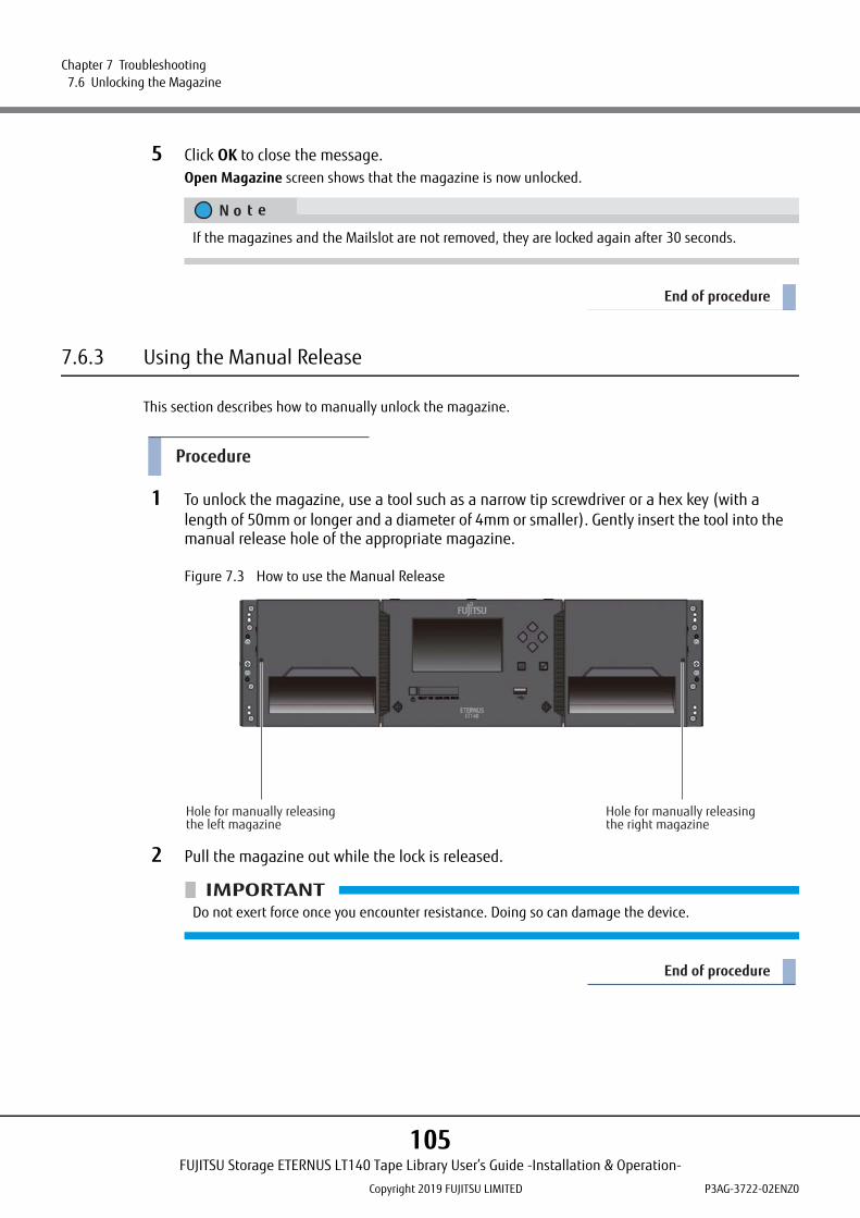
Chapter 7 Troubleshooting 7.6 Unlocking the Magazine
5 Click OK to close the message.Open Magazine screen shows that the magazine is now unlocked.
End of procedure
7.6.3 Using the Manual Release
This section describes how to manually unlock the magazine.
Procedure
1 To unlock the magazine, use a tool such as a narrow tip screwdriver or a hex key (with a length of 50mm or longer and a diameter of 4mm or smaller). Gently insert the tool into the manual release hole of the appropriate magazine.
Figure 7.3 How to use the Manual Release
2 Pull the magazine out while the lock is released.
End of procedure
If the magazines and the Mailslot are not removed, they are locked again after 30 seconds.
Do not exert force once you encounter resistance. Doing so can damage the device.
Hole for manually releasing the left magazine
Hole for manually releasing the right magazine
FUJITSU Storage ETERNUS LT140 Tape Library User’s Guide -Installation & Operation-
Copyright 2019 FUJITSU LIMITED P3AG-3722-02ENZ0
105
Chapter 7 Troubleshooting 7.7 Unloading a Stuck Tape
7.7 Unloading a Stuck Tape
If the tape is stuck in a tape drive, eject the tape from the tape drive in the Operation > Force Drive MediaEject screen.If a tape is stuck in a magazine, open the magazine, grasp the cartridge, and pull it out of the slot.
7.8 Identifying a Failed Component
This section describes how to identify failed components.
Procedure
1 Activate the UID LEDs from the Maintenance > UID LED Control screen.This will illuminate the blue LED on the front and rear of the Base Module to identify the librarycontaining the failed module or component.
2 Identify which of the modules (Base or Expansion) in the library contains the failed component.
2-1 In the upper left of the Home screen, locate the module that indicates an error.
2-2 Click or tap the module for information on the failed component.
End of procedure
FUJITSU Storage ETERNUS LT140 Tape Library User’s Guide -Installation & Operation-
Copyright 2019 FUJITSU LIMITED P3AG-3722-02ENZ0
106

Chapter 7 Troubleshooting 7.9 Returning the Robotic Assembly to the Base Module
7.9 Returning the Robotic Assembly to the Base Module
If you have powered off the library and the robotic assembly did not return to its park position in the BaseModule behind the operator panel:
Procedure
1 Power on the library by pressing the power button on the Base Module.
2 From the remote panel, return the robotic assembly to its park position from the Maintenance > Move Robotic to Base Module screen.
3 Power off the library by pressing the power button on the Base Module and holding for 3 seconds.
End of procedure
If the robotic assembly is still not in the Base Module, contact your maintenance engineer.
7.10 Running Library Tests
The library provides tests to verify library operations.
• Wellness TestRefer to "3.5.1.5 Wellness Test" in "FUJITSU Storage ETERNUS LT140 Tape Library User's Guide -PanelOperation-".
• System TestExercises overall library functionality by moving cartridges within the library.Cartridges are returned to their original location.Refer to "3.5.1.1 System Test" in "FUJITSU Storage ETERNUS LT140 Tape Library User's Guide -PanelOperation-".
• Slot to Slot TestRandomly exchanges cartridges within the library.Cartridges are NOT returned to their original locations.Refer to "3.5.1.2 Slot to Slot Test" in "FUJITSU Storage ETERNUS LT140 Tape Library User's Guide -PanelOperation-".
• Element to Element TestMoves a cartridge to a specific element and then returns it to its original location.Refer to "3.5.1.3 Element to Element Test" in "FUJITSU Storage ETERNUS LT140 Tape Library User's Guide -Panel Operation-".
FUJITSU Storage ETERNUS LT140 Tape Library User’s Guide -Installation & Operation-
Copyright 2019 FUJITSU LIMITED P3AG-3722-02ENZ0
107

Chapter 7 Troubleshooting 7.11 Assistance during Maintenance
• Position TestMoves the robotic assembly vertically between two elements. The number of movements can be specified.The robotic assembly does not move cartridges in this test.Refer to "3.5.1.4 Position Test" in "FUJITSU Storage ETERNUS LT140 Tape Library User's Guide -PanelOperation-".
• Robotic TestPerforms a full inventory and exercises all robotic assembly movements and sensors.Refer to "3.5.1.6 Robotic Test" in "FUJITSU Storage ETERNUS LT140 Tape Library User's Guide -PanelOperation-".
• Operator Panel LED TestTurn the LEDs on of the operator panel.Refer to "3.5.1.7 Operator Panel Test" in "FUJITSU Storage ETERNUS LT140 Tape Library User's Guide -PanelOperation-".
7.11 Assistance during Maintenance
Your maintenance engineer may ask you to collect the log files when troubleshooting the error. For detailsabout how to collect log files, refer to "3.5.5 Downloading Drive Logs" and "3.5.6 Downloading Logs and TraceFiles" in "FUJITSU Storage ETERNUS LT140 Tape Library User’s Guide -Panel Operation-".To replace maintenance parts other than the library magazines due to, for example, a tape library failure, stopthe backup software and power off the tape library. In addition, note that the server must be rebooted afterthe maintenance parts are replaced.
7.12 User Operations after Replacing Maintenance Parts
When maintenance parts are replaced due to, for example, a tape library failure, users need to performoperations such as those shown below.
• Rebooting the server• Resetting the backup software• Initial settings
Refer to "4.2 Using the Initial System Setup" (page 56) for instructions on the initial settings.• Restoring the library configuration
Refer to "3.4.2 Saving, Restoring, and Resetting the Library Configuration" in "FUJITSU Storage ETERNUSLT140 Tape Library User’s Guide -Panel Operation-" for instructions on how to restore the library configura-tion.
• Importing the master key and encryption key (when using the Key Management Function Option)Refer to "FUJITSU Storage ETERNUS LT140 Tape Library Key Management Function Option User’s Guide" forinstructions on how to import the master key or encryption key.
FUJITSU Storage ETERNUS LT140 Tape Library User’s Guide -Installation & Operation-
Copyright 2019 FUJITSU LIMITED P3AG-3722-02ENZ0
108
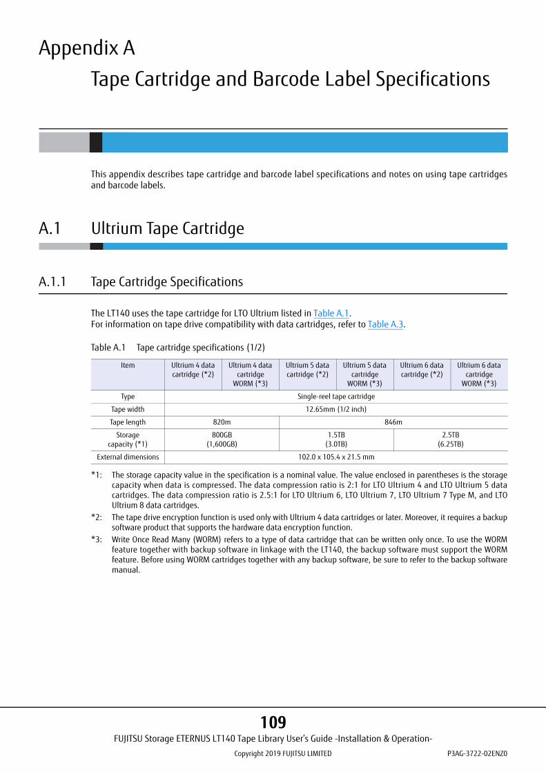
Appendix A
Tape Cartridge and Barcode Label Specifications
This appendix describes tape cartridge and barcode label specifications and notes on using tape cartridgesand barcode labels.
A.1 Ultrium Tape Cartridge
A.1.1 Tape Cartridge Specifications
The LT140 uses the tape cartridge for LTO Ultrium listed in Table A.1.For information on tape drive compatibility with data cartridges, refer to Table A.3.
Table A.1 Tape cartridge specifications (1/2)
*1: The storage capacity value in the specification is a nominal value. The value enclosed in parentheses is the storagecapacity when data is compressed. The data compression ratio is 2:1 for LTO Ultrium 4 and LTO Ultrium 5 datacartridges. The data compression ratio is 2.5:1 for LTO Ultrium 6, LTO Ultrium 7, LTO Ultrium 7 Type M, and LTOUltrium 8 data cartridges.
*2: The tape drive encryption function is used only with Ultrium 4 data cartridges or later. Moreover, it requires a backupsoftware product that supports the hardware data encryption function.
*3: Write Once Read Many (WORM) refers to a type of data cartridge that can be written only once. To use the WORMfeature together with backup software in linkage with the LT140, the backup software must support the WORMfeature. Before using WORM cartridges together with any backup software, be sure to refer to the backup softwaremanual.
Item Ultrium 4 data cartridge (*2)
Ultrium 4 data cartridge
WORM (*3)
Ultrium 5 data cartridge (*2)
Ultrium 5 data cartridge
WORM (*3)
Ultrium 6 data cartridge (*2)
Ultrium 6 data cartridge
WORM (*3)
Type Single-reel tape cartridge
Tape width 12.65mm (1/2 inch)
Tape length 820m 846m
Storage capacity (*1)
800GB (1,600GB)
1.5TB (3.0TB)
2.5TB (6.25TB)
External dimensions 102.0 x 105.4 x 21.5 mm
FUJITSU Storage ETERNUS LT140 Tape Library User’s Guide -Installation & Operation-
Copyright 2019 FUJITSU LIMITED P3AG-3722-02ENZ0
109

Appendix A Tape Cartridge and Barcode Label Specifications A.1 Ultrium Tape Cartridge
Table A.2 Tape cartridge specifications (2/2)
*1: The storage capacity value in the specification is a nominal value. The value enclosed in parentheses is the storagecapacity when data is compressed. The data compression ratio is 2:1 for LTO Ultrium 4 and LTO Ultrium 5 datacartridges. The data compression ratio is 2.5:1 for LTO Ultrium 6, LTO Ultrium 7, LTO Ultrium 7 Type M, and LTOUltrium 8 data cartridges.
*2: The tape drive encryption function is used only with Ultrium 4 data cartridges or later. Moreover, it requires a backupsoftware product that supports the hardware data encryption function.
*3: Write Once Read Many (WORM) refers to a type of data cartridge that can be written only once. To use the WORMfeature together with backup software in linkage with the LT140, the backup software must support the WORMfeature. Before using WORM cartridges together with any backup software, be sure to refer to the backup softwaremanual.
*4: The cleaning cartridge is common to and can be used with Ultrium 1 to Ultrium 8 drives.
• A cartridge can be used up to 50 times as a rough standard. After approximately 50 uses, this cartridge can no longer be used. Fujitsu recommends replacing it before the 50th time.
• Be sure not to use a cleaning cartridge intended for another LT series tape library, or a cleaning cartridge already used on a tape library manufactured by another company. Otherwise, errors and other problems may occur.
• For details on how to use cleaning cartridges, refer to "3.6 Cleaning Tape Drives" (page 51).
Item Ultrium 7 data cartridge (*2)
Ultrium 7 data cartridge
WORM (*3)
Ultrium 7 Type M data
cartridge (*2)
Ultrium 8 data cartridge (*2)
Ultrium 8 data cartridge
WORM (*3)
Ultrium 1 cleaning
cartridge U (*4)
Type Single-reel tape cartridge
Tape width 12.65mm (1/2 inch)
Tape length 960m 305m
Storage capacity (*1)
6.0TB (15.0TB)
9.0TB (22.5TB)
12.0TB (30.0TB)
-
External dimensions 102.0 x 105.4 x 21.5 mm
FUJITSU Storage ETERNUS LT140 Tape Library User’s Guide -Installation & Operation-
Copyright 2019 FUJITSU LIMITED P3AG-3722-02ENZ0
110
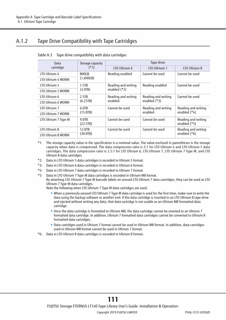
Appendix A Tape Cartridge and Barcode Label Specifications A.1 Ultrium Tape Cartridge
A.1.2 Tape Drive Compatibility with Tape Cartridges
Table A.3 Tape drive compatibility with data cartridges
*1: The storage capacity value in the specification is a nominal value. The value enclosed in parentheses is the storagecapacity when data is compressed. The data compression ratio is 2:1 for LTO Ultrium 4 and LTO Ultrium 5 datacartridges. The data compression ratio is 2.5:1 for LTO Ultrium 6, LTO Ultrium 7, LTO Ultrium 7 Type M, and LTOUltrium 8 data cartridges.
*2: Data in LTO Ultrium 5 data cartridges is recorded in Ultrium 5 format.*3: Data in LTO Ultrium 6 data cartridges is recorded in Ultrium 6 format.*4: Data in LTO Ultrium 7 data cartridges is recorded in Ultrium 7 format.*5: Data in LTO Ultrium 7 Type M data cartridges is recorded in Ultrium M8 format.
By attaching LTO Ultrium 7 Type M barcode labels on unused LTO Ultrium 7 data cartridges, they can be used as LTOUltrium 7 Type M data cartridges.Note the following when LTO Ultrium 7 Type M data cartridges are used.
• When a previously unused LTO Ultrium 7 Type M data cartridge is used for the first time, make sure to write the data using the backup software or another tool. If the data cartridge is inserted in an LTO Ultrium 8 tape drive and ejected without writing any data, that data cartridge is not usable as an Ultrium M8 formatted data cartridge.
• Once the data cartridge is formatted to Ultrium M8, the data cartridge cannot be reverted to an Ultrium 7 formatted data cartridge. In addition, Ultrium 7 formatted data cartridges cannot be converted to Ultrium 8 formatted data cartridges.
• Data cartridges used in Ultrium 7 format cannot be used in Ultrium M8 format. In addition, data cartridges used in Ultrium M8 format cannot be used in Ultrium 7 format.
*6: Data in LTO Ultrium 8 data cartridges is recorded in Ultrium 8 format.
Datacartridge
Storage capacity (*1)
Tape drive
LTO Ultrium 6 LTO Ultrium 7 LTO Ultrium 8
LTO Ultrium 4 800GB(1,600GB)
Reading enabled Cannot be used Cannot be used
LTO Ultrium 4 WORM
LTO Ultrium 5 1.5TB(3.0TB)
Reading and writing enabled (*2)
Reading enabled Cannot be used
LTO Ultrium 5 WORM
LTO Ultrium 6 2.5TB(6.25TB)
Reading and writing enabled
Reading and writing enabled (*3)
Cannot be used
LTO Ultrium 6 WORM
LTO Ultrium 7 6.0TB(15.0TB)
Cannot be used Reading and writing enabled
Reading and writing enabled (*4)LTO Ultrium 7 WORM
LTO Ultrium 7 Type M 9.0TB(22.5TB)
Cannot be used Cannot be used Reading and writing enabled (*5)
LTO Ultrium 8 12.0TB(30.0TB)
Cannot be used Cannot be used Reading and writing enabled (*6)LTO Ultrium 8 WORM
FUJITSU Storage ETERNUS LT140 Tape Library User’s Guide -Installation & Operation-
Copyright 2019 FUJITSU LIMITED P3AG-3722-02ENZ0
111

Appendix A Tape Cartridge and Barcode Label Specifications A.1 Ultrium Tape Cartridge
A.1.3 Notes Regarding the Use of Tape Cartridges
To assure required performance and reliability, tape cartridges must be handled with care. A tape cartridge isa consumable, meaning that it wears out after a certain period of use.
■ Precautions to Follow when Using the Tape Cartridge
• The Ultrium drives of the LT140 are dedicated drives for LTO Ultrium cartridges. In addition to the LT140, these tape cartridges can also be used with the LT20 S2, LT40 S2, LT60 S2, LT130, LT160, LT200, LT210, LT220, LT230, LT250, LT260, LT270, and LT270 S2. Note that DLT, 8 mm, DDS, LT300 tape cartridges and the like cannot be used with Ultrium tape drives.
• The data cartridge and the cleaning cartridge are consumable supplies. Be sure to purchase them separately. For details of the tape cartridge specifications, refer to "A.1.1 Tape Cartridge Specifications" (page 109).
• A cleaning cartridge can be used up to 50 times as a rough standard. If the maximum number is reached, replace the cleaning cartridge.
• A cleaning cartridge is for exclusive use in the tape library device being used. Be sure not to use a cleaning cartridge in the LT140 Tape Library that was used in another library device.
• To use a data cartridge that was used in another library device in this library, check the following points. If any relevant point is found, perform recovery work or replacement with a new one before using LT140.
- Barcode labelUse the tape cartridge vendor's label for the barcode label to be affixed to the cartridge. For details onthe specifications, refer to "A.2 Barcode Labels" (page 118).
- Leader pinCheck for any leader pin that has been detached from the tape cartridge. For more details on leaderpins, refer to "A.1.4 Handling Tape Cartridges" (page 113).
- Replacement cycle of tape cartridgesA tape cartridge, being a consumable, wears out due to mechanical abrasion and/or chemicaldeterioration. If storage under the environment conditions recommended by Fujitsu is assumed, theservice life of the tape cartridge is about 30 years. However, if circumstances such as the environmentfor use, number of times of use, and storage environment are considered for actual operation, werecommend replacing the tape cartridge with a new one.
FUJITSU Storage ETERNUS LT140 Tape Library User’s Guide -Installation & Operation-
Copyright 2019 FUJITSU LIMITED P3AG-3722-02ENZ0
112
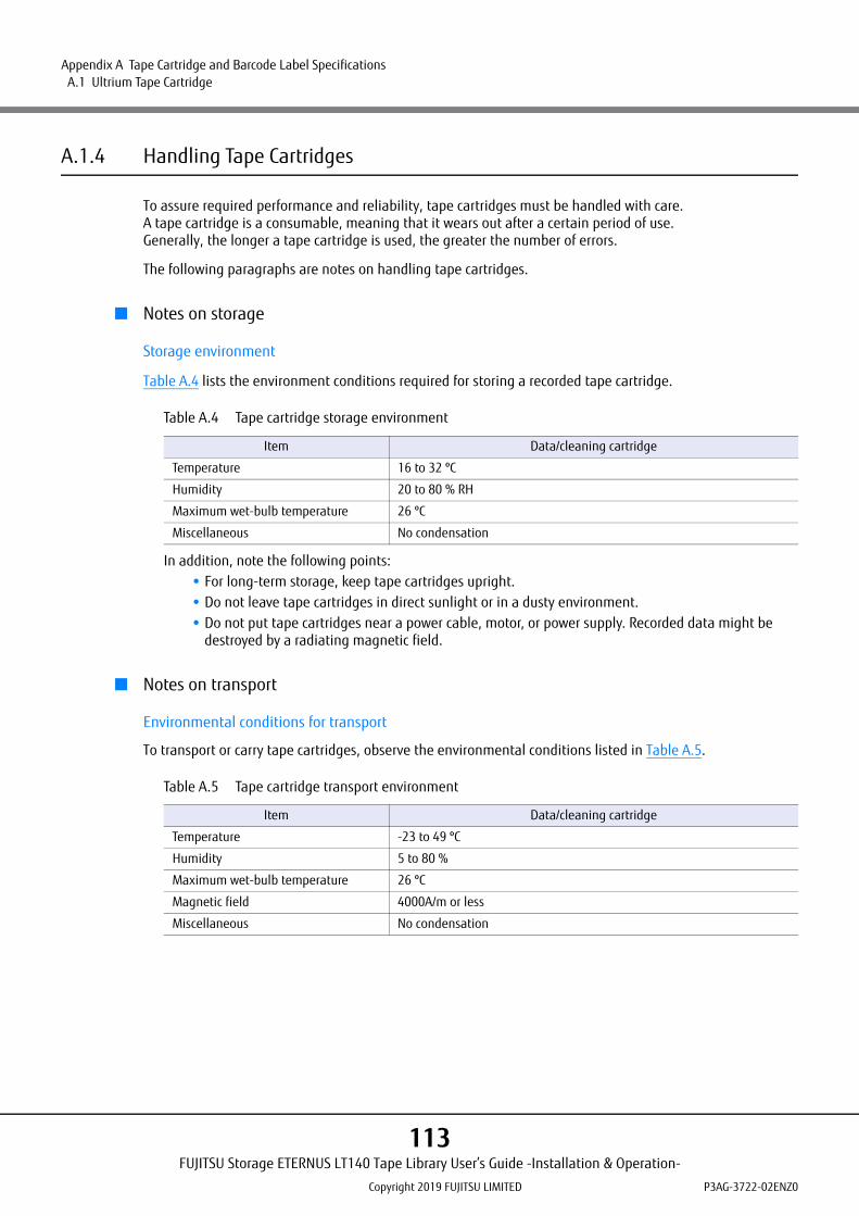
Appendix A Tape Cartridge and Barcode Label Specifications A.1 Ultrium Tape Cartridge
A.1.4 Handling Tape Cartridges
To assure required performance and reliability, tape cartridges must be handled with care.A tape cartridge is a consumable, meaning that it wears out after a certain period of use.Generally, the longer a tape cartridge is used, the greater the number of errors.
The following paragraphs are notes on handling tape cartridges.
■ Notes on storage
Storage environment
Table A.4 lists the environment conditions required for storing a recorded tape cartridge.
Table A.4 Tape cartridge storage environment
In addition, note the following points:• For long-term storage, keep tape cartridges upright.• Do not leave tape cartridges in direct sunlight or in a dusty environment.• Do not put tape cartridges near a power cable, motor, or power supply. Recorded data might be
destroyed by a radiating magnetic field.
■ Notes on transport
Environmental conditions for transport
To transport or carry tape cartridges, observe the environmental conditions listed in Table A.5.
Table A.5 Tape cartridge transport environment
Item Data/cleaning cartridge
Temperature 16 to 32 ºC
Humidity 20 to 80 % RH
Maximum wet-bulb temperature 26 ºC
Miscellaneous No condensation
Item Data/cleaning cartridge
Temperature -23 to 49 ºC
Humidity 5 to 80 %
Maximum wet-bulb temperature 26 ºC
Magnetic field 4000A/m or less
Miscellaneous No condensation
FUJITSU Storage ETERNUS LT140 Tape Library User’s Guide -Installation & Operation-
Copyright 2019 FUJITSU LIMITED P3AG-3722-02ENZ0
113

Appendix A Tape Cartridge and Barcode Label Specifications A.1 Ultrium Tape Cartridge
In addition, note the following points:• When using a tape cartridge brought in from outdoors, avoid any sudden changes in the
environment, and let the tape adapt to the operating environment by exposing as long as it has been stored outside (up to 24 hours).Example:
- Outside for six hoursLeave the tape cartridge in the operating environment for six hours to let it adapt before usingit.
- Outside for one day or moreLeave the tape cartridge in the operating environment for 24 hours to let it adapt before usingit.
• During transportation, put the tape cartridge in a container to protect it from water damage, contamination, magnetic fields, temperature changes, vibration, and shock.
■ Handling
This section provides notes on handling tape cartridges.• To prevent tape cartridges from falling, do not stack them more than six cartridges high. If you damage a
cartridge by mistakenly allowing it to fall, repair the cartridge and immediately copy the data to other medium. After doing so, dispose of the damaged cartridge.
• An LTO Ultrium tape cartridge has a factory-written servo track, enabling precise reading and writing to the tape using this information. Although data can be deleted using a dedicated device (1200 oersteds or more) for security protection of the data, the servo track is also deleted. Thus, a cartridge whose data has been deleted cannot be reused.
• Due to chemical deterioration of tape cartridges, an adhesive constituent in the tape binder might sometimes ooze and stick to the magnetic head, causing read/write errors.
If an adhesive contaminant sticks to the head, a chemical contained in the contaminant (binderconstituent) might corrode the MR element of the head. Since this adhesive contaminant oozes regardlessof the number of times the tape is used, tape cleaning does not solve the problem; the only solution is todispose of the tape.In addition, an adhesive contaminant tends to emerge if a tape is stored in a hot or humid environment.Maintenance of the correct storage environment is important.
FUJITSU Storage ETERNUS LT140 Tape Library User’s Guide -Installation & Operation-
Copyright 2019 FUJITSU LIMITED P3AG-3722-02ENZ0
114

Appendix A Tape Cartridge and Barcode Label Specifications A.1 Ultrium Tape Cartridge
■ Notes on the shutter and leader pin
Before loading a tape cartridge in the device, confirm that the tape cartridge shutter can open and close andthat the leader pin has been removed from the tape cartridge.If the shutter cannot open and close normally, do not use the tape cartridge because loading it in a tape drivemay not be possible. In addition, even if the leader pin of a tape cartridge with recorded data has beenremoved, the tape cartridge can be used again with the leader pin reattached to the cartridge. In such cases,contact the support section. Note that repairs to a tape are limited to within 30 cm from the end of the tape.
The procedure to check a shutter and a leader pin is as follows:
Procedure
1 Before using a tape cartridge, confirm that its leader pin is latched.
Figure A.1 Latched state of the leader pin (the leader pin is latched)
Figure A.2 Latched state of the leader pin (the leader pin has been removed)
FUJITSU Storage ETERNUS LT140 Tape Library User’s Guide -Installation & Operation-
Copyright 2019 FUJITSU LIMITED P3AG-3722-02ENZ0
115

Appendix A Tape Cartridge and Barcode Label Specifications A.1 Ultrium Tape Cartridge
2 Confirm that the tape is correctly attached with clips to the leader pin.Do not use the tape cartridge until the clips are verified as fitting correctly into the leader pin as shownbelow.
Figure A.3 Fit state of clips (clips fit correctly)
Figure A.4 Fit state of clips (clips do not fit correctly (the leader pin is misaligned))
End of procedure
Do not apply force to or pull out the leader pin or tape of a tape cartridge because it is a precision component. Do not push or turn the reel.
FUJITSU Storage ETERNUS LT140 Tape Library User’s Guide -Installation & Operation-
Copyright 2019 FUJITSU LIMITED P3AG-3722-02ENZ0
116

Appendix A Tape Cartridge and Barcode Label Specifications A.1 Ultrium Tape Cartridge
■ Notes when handling the tape cartridges
Because the data cartridge is a precision product with an enclosed structure, be sure to keep the following inmind when inspecting it.
• Do not drop the data cartridge or expose it to shock or vibration.• Do not apply excessive force to the data cartridge, or pull on the leader pin or the magnetic tape.• Do not press on the magnetic tape reel or turn it.
■ Notes on affixing a label
It is important to affix a highly adhesive, high-quality label on each tape cartridge.Loading a tape cartridge whose label is loose will cause problems in the LT140.Therefore, be sure to use the labels provided with the tape cartridges.
FUJITSU Storage ETERNUS LT140 Tape Library User’s Guide -Installation & Operation-
Copyright 2019 FUJITSU LIMITED P3AG-3722-02ENZ0
117

Appendix A Tape Cartridge and Barcode Label Specifications A.2 Barcode Labels
A.2 Barcode Labels
Barcode-based operation is required for the LT140. Purchase and use the barcode labels available from EDP/COLORFLEX or the magnetic tape vendor.
Data cartridge label: EDP/Colorflex #1700-00Cleaning cartridge label: EDP/Colorflex #1700-CN
A.2.1 Barcode Label Specifications
When purchasing labels, specify an eight-character string indicating the "volume area + media area."
Figure A.5 Character string on barcode label
For data cartridge For cleaning cartridge
Volume Area
Media Area
Starting Quiet Zone
Start Character
Character L
Character T
Character 0
Character 1
Character 2
Character 3
Media Character L
Media Character 1
Stop Character
Ending Quiet Zone
17
79
FUJITSU Storage ETERNUS LT140 Tape Library User’s Guide -Installation & Operation-
Copyright 2019 FUJITSU LIMITED P3AG-3722-02ENZ0
118

Appendix A Tape Cartridge and Barcode Label Specifications A.2 Barcode Labels
■ Specifying a character string in the volume area (Volser)
Strings in the volume area of the data cartridges are six-character strings. However, note that the following six-character strings cannot be used:"CLNxxx", "DGxxxx, and "CEVLxx" (x is an arbitrary character string)Table A.6 lists the characters that can be used in the volume area.
Table A.6 Characters that can be used on barcode labels
■ Specifying a string in the media area (Media ID)
Table A.7 shows the relationship between the cartridge type and the specified string.
Table A.7 Cartridge type and specified string
■ Specifying a string on a cleaning cartridge label
Specify the character strings of a cleaning cartridge barcode label as "CLNU xx L1" (where xx represents anyusable characters).
Character type Description
Upper-case alphabetic character 26 characters from A to Z
Numeric characters 10 characters from 0 to 9
Specified string Tape cartridge type
L1 Ultrium 1 data cartridge 100GB (Non-compressed), 200GB (Compressed)
L2 Ultrium 2 data cartridge 200GB (Non-compressed), 400GB (Compressed)
L3 Ultrium 3 data cartridge 400GB (Non-compressed), 800GB (Compressed)
L4 Ultrium 4 data cartridge 800GB (Non-compressed), 1,600GB (Compressed)
L5 Ultrium 5 data cartridge 1.5TB (Non-compressed), 3.0TB (Compressed)
L6 Ultrium 6 data cartridge 2.5TB (Non-compressed), 6.25TB (Compressed)
L7 Ultrium 7 data cartridge 6.0TB (Non-compressed), 15.0TB (Compressed)
M8 Ultrium 7 Type M data cartridge 9.0TB (Non-compressed), 22.5TB (Compressed)
L8 Ultrium 8 data cartridge 12.0GB (Non-compressed), 30.0GB (Compressed)
LT Ultrium 3 data cartridge WORM 400GB (Non-compressed), 800GB (Compressed)
LU Ultrium 4 data cartridge WORM 800GB (Non-compressed), 1,600GB (Compressed)
LV Ultrium 5 data cartridge WORM 1.5TB (Non-compressed), 3.0TB (Compressed)
LW Ultrium 6 data cartridge WORM 2.5TB (Non-compressed), 6.25TB (Compressed)
LX Ultrium 7 data cartridge WORM 6.0TB (Non-compressed), 15.0TB (Compressed)
LY Ultrium 8 data cartridge WORM 12.0TB (Non-compressed), 30.0TB (Compressed)
FUJITSU Storage ETERNUS LT140 Tape Library User’s Guide -Installation & Operation-
Copyright 2019 FUJITSU LIMITED P3AG-3722-02ENZ0
119

Appendix A Tape Cartridge and Barcode Label Specifications A.2 Barcode Labels
A.2.2 Notes on Affixing a Barcode Label
• Keep the surface clean and free of fingerprints or dirt.
• Affix the barcode label on the specified location (concavity beside the write-protect switch) of the tape cartridge correctly (refer to Figure A.6).The barcode may not be recognized if the label is affixed in an incorrect position or orientation or if the label is wrinkled.
• After affixing the barcode label, press on it firmly. Notice that the end parts of the label are easily broken.
• To replace the label, peel the old label from the tape and then affix a new one.
Figure A.6 Barcode label affixing location
Write-protect switch
Label Affixing Position
FUJITSU Storage ETERNUS LT140 Tape Library User’s Guide -Installation & Operation-
Copyright 2019 FUJITSU LIMITED P3AG-3722-02ENZ0
120
FUJITSU Storage ETERNUS LT140 Tape LibraryUser's Guide -Installation & Operation-
P3AG-3722-02ENZ0
Date of issuance : December 2019Issuance responsibility : FUJITSU LIMITED
• The content of this manual is subject to change without notice.
• This manual was prepared with the utmost attention to detail. However, Fujitsu shall assume no responsibility for any operational problems as the result of errors, omissions, or the use of information in this manual.
• Fujitsu assumes no liability for damages to third party copyrights or other rights arising from the use of any information in this manual.
• The content of this manual may not be reproduced or distributed in part or in its entirety without prior permission from Fujitsu.