full cs product catalog_2013
DESCRIPTION
Pistos Website BrochuresTRANSCRIPT

Proven and innovativemeasuring technology forcompressed air and gases
Catalogue for measuring professionals 2013
ckluft
ADew point
Current
Pressure
Leakage
Consumption
Temperature
2 www.cs-instruments.com
Table of contents
Calibration
Digitaldisplays
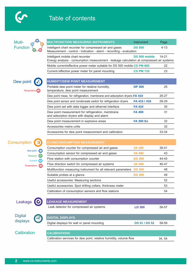
MULTIFUNCTION MEASURING INSTRUMENTS Instrument Page
Intelligent chart recorder for compressed air and gases DS 500 4-13Measurement - control - indication - alarm - recording - evaluation
Intelligent mobile chart recorder DS 500 mobile 14-21Energy analysis - consumption measurement - leakage calculation at compressed air systems
Mobile current/effective power meter suitable for DS 500 mobile CS PM 600 22
Current/effective power meter for panel mounting CS PM 710 23
Multi-Function
HUMIDITY/DEW POINT MEASUREMENT
Portable dew point meter for relative humidity, DP 300 25temperature, dew point measurement
Dew point meas. for refrigeration, membrane and adsorption dryers FA 410 26-27
Dew point sensor and condensate switch for refrigeration dryers FA 415 / 416 28-29
Dew point set with data logger and ethernet interface FA 410 30
Dew point measurement for refrigeration, membrane FA 400 31and adsorption dryers with display and alarm
Dew point measurement in explosive areas FA 300 Ex 32
Accessories mains units 32
Accessories for dew point measurement and calibration 33-34
FLOW/CONSUMPTION MEASUREMENT
Consumption counter for compressed air and gases VA 420 36-41
Consumption sensor for compressed air and gases VA 400 43
Flow station with consumption counter DS 300 44-45
Flow direction switch for compressed air systems VA 409 46-47
Multifunction measuring instrument for all relevant parameters DS 300 48
Suitable probes at a glance DS 300 49
Useful accessories: Measuring sections 52
Useful accessories: Spot drilling collars, thickness meter 53
Calibration of consumption sensors and flow stations 54
LEAKAGE MEASUREMENT Leak detector for compressed air systems LD 300 56-57
DIGITAL DISPLAYS
Digital displays for wall or panel mounting DS 51 / DS 52 58-59
CALIBRATIONS
Calibration services for dew point, relative humidity, volume flow 34, 54
Consumption
Leakage
Dew point
Temperature
Temperature
Dew point
Pressure
Current

www.cs-instruments.com 3
Sales Office NorthCS INSTRUMENTS GMBHAm Oxer 28cD-24955 HarrisleePhone +49 (0) 461 700 20 25Fax +49 (0) 461 700 20 [email protected]
Sales Office South CS INSTRUMENTS GMBHZindelsteiner Straße 15D-78052 VS-TannheimPhone +49 (0) 7705 978 99-0Fax +49 (0) 7705 978 [email protected]
Confidence is good – measuring is betterApproven and innovative measuring technology of CS Instruments GmbH
Welcome to the new CS Instruments catalogue 2013 drawn up for measuring professionals.
Increasing energy costs force many enter-prises to use possible savings in case of different kinds of energy like compressed air, electrical energy, gas, cooling energy/
Picture:DS 500 (For details please see pages 4 to 13)
water meters, gas meters etc.) can be connected to DS 500 and evaluated automatically.
Daily, weekly or monthly reports give a quick survey on the consumption and the cost savings of saving measures which have been carried out.
thermal energy, … For this purpose the consumptions and the costs within an enterprise have to be transparent.
CS Instruments GmbH accommodated this trend with its newly developed intelligent chart recorder DS 500. Up to 12 energy counters (current counters, heat meters,

4 www.cs-instruments.com
Multifunction
For more than 20 years CS Instruments has been developing, manufacturing and marke-ting measuring instruments for compressed air and gases. From recording of the measured data, indication on a big colour screen, alerting, storage up to remote read-out via web-server … this is all possible with DS 500. By means of the CS Soft software alarms can be sent via SMS or e-mail. All measured values, measured curves and threshold exceedings are indicated. The curve progressions from the beginning of the measurement can be viewed by an easy slide of the finger.
Daily/weekly/monthly reports with costs in € and counter reading in m³ for each consumption sensor are completing the sophisticated system concept. The big difference to ordinary paperless chart recorders reveals in the easy initiation and in the evaluation of the measured data. All sensors are identified directly and powered by DS 500. Everything is matchedand tuned.Mathematical function for internal calculations, e. g. the typical figures of acompressed air plant:- costs in € per generated m³ air- kWh/m³ generated air
- consumption of single lines including - summationTotalizer function for analogue signals (e. g. 0/4…20 mA, 0…10 V). In case of third-party sensors which e. g. only give a 4…20 mA signal for the actual flow in m³/h a total counter reading in m³ can be generated by means of the totalizer function.
No time consuming studying of the instruction manual … this saves time. Internal voltage supply of all sensors,no wiring of external mains units … this saves additional costs.
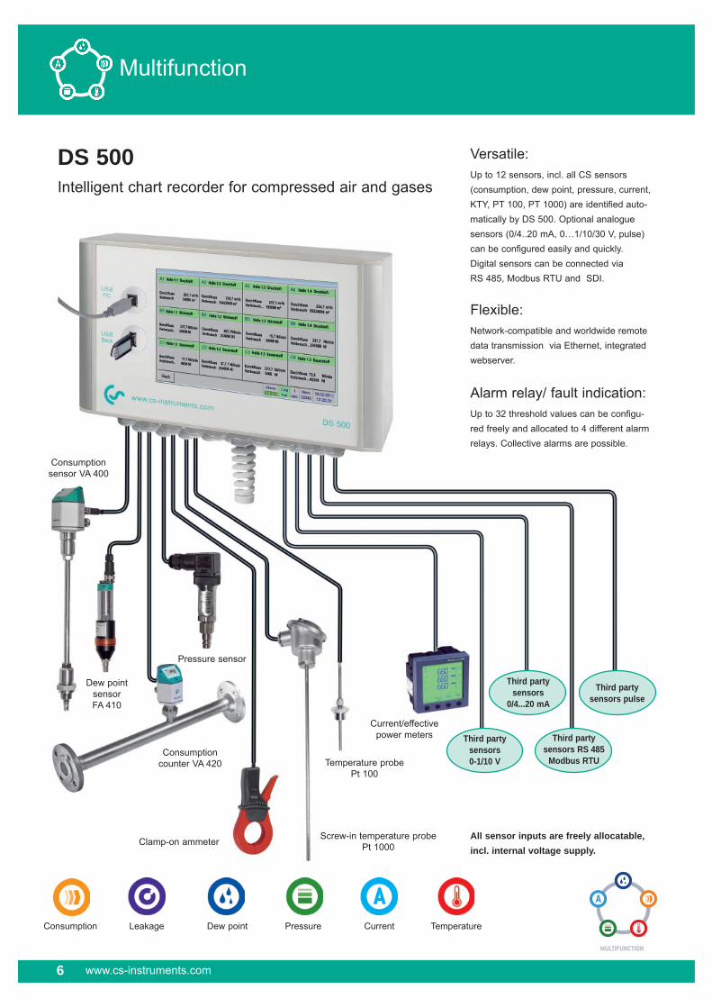
DS 500 Intelligent chart recorder for compressed air and gases
Measurement - control - indication - alarm - recording - evaluation
Advantages at a glance:
� Clear layout: 7" colour screen with touch panel…
� Versatile: Up to 12 optional sensors can be connected…
� Suitable for industrial applications: Metal housing IP 65 or panel mounting…
� Data available though world wide web: Network-compatible and remote transmission via webserver
� Intelligent: Daily/weekly monthly reports…
� Mathematical function for internal calculations
� Totalizer function for analogue signals
� … Saves time and costs during installation
DS 500 — the intelligent chart recorder of the next generation

www.cs-instruments.com 5
Multifunction
Anwendungstechnische Merkmale der Verbrauchszähler VA 420:
Description Order no.
DS 500 - intelligent chart recorder in basic version (4 sensor inputs) 0500 5000Option 4 additional sensor inputs for DS 500 Z500 5001Option 8 additional sensor inputs for DS 500 Z500 5002 Option Integrated webserver Z500.5003Option "consumption report" statistics, daily/weekly/monthly report Z500.5004Option "quick measurement with 10 msec sampling rate” for analogue sensors Z500.5005Option version for panel mounting Z500.5006Option power supply 24VDC (instead of 100...240 VAC) Z500.5007Option “mathematics calculat. function” for 4 freely selectable “virtual” channels, Z500 5008(mathematical functions: addition, subtraction, division, multiplication) Option: "Totalizer function for analogue signals" Z500 5009 CS Soft Basic for DS 500 - data evaluation in graphic and table form, 0554.7040 reading out of the measured data of one DS 500 via USB or EthernetCS Soft Network - Database Client/Server Solution (up to 5 DS 500) - 0554.7041 database (MySQL) to Server - data evaluation via Client-Software CS Soft Network - Database Client/Server Solution (up to 10 DS 500) - 0554.7042 database (MySQL) to Server - data evaluation via Client-Software CS Soft Network - Database Client/Server Solution (up to 20 DS 500) - 0554.7043database (MySQL) to Server - data evaluation via Client-Software CS Soft Network - Database Client/Server Solution (> 20 DS 500) - 0554.7044database (MySQL) to Server - data evaluation via Client-Software
Input signals
Current signal (0...20mA/4...20mA) internal or external power supplyMeasuring range 0…20 mAResolution 0.0001 mAAccuracy ± 0.003 mA ± 0.05 %Input resistance 50 �
Voltage signal (0...1 V)Measuring range 0…1 VResolution 0.05 mV Accuracy ± 0.2 mV ± 0.05 %Input resistance 100 k�
Voltage signal (0...10 V / 30 V)Measuring range 0…10 VResolution 0.5 mV Accuracy ± 2 mV ± 0.05 %Input resistance 1 M�
RTD Pt 100Measuring range -200…850° CResolution 0.1° C Accuracy ± 0.2°C (-100...400°C) ± 0.3°C (further range)
RTD Pt 1000Measuring range -200…850° CResolution 0.1° C Accuracy ± 0.2° (-100...400°C)
Pulse Measuring range min pulse length 100 μs frequency 0...1 kHz max. 30 VDC
Technical data DS 500Dimensions of housing 280 x 170 x 90 mm, IP 65 Connections 18 x PG 12 for sensors and supply, alarm relays 1 x RJ 45 Ethernet connection Version panel mounting Cutout panel 250 x 156 mmWeight 7.3 kgMaterial Die cast metal, front screen polyesterSensor inputs 4/8/12 sensor inputs for analogue and digital sensors freely allocatable. See options Digital CS sensors for dew point and consumption with SDI interface FA/VA 400 Series, Digital third-party sensors RS 485 / Modbus RTU, other Bus systems realizable on request Analogue CS sensors for pressure, temperature, clamp-on ammeters preconfigured Analogue third-party sensors 0/4 ..20 mA, 0..1/10/30V, pulse, Pt 100 / Pt 1000, KTY Power supply for 24 VDC, max. 130 mA per sensor, integrated mains unit sensors max. 24 VDC, 25 W in case of version 8/12 sensor inputs 2 integrated mains units each max.24 VDC, 25 Watt Interfaces USB stick, USB cable, Ethernet / RS 485 Modbus RTU / TCP, SDI other bus systems on request, WEB server optionallyOutputs 4 relays (changeover contact 230 VAC, 6 A), alarm management, relays freely programmable, collective alarm Analogue output, pulse in case of sensors with own signal output looped, like e. g. VA/FA SeriesMemory card Memory size 2 GB SD memory card standard, optionally up to 4 GB Power supply 100...240 VAC / 50-60 Hz, special version 24 VDC Colour screen 7" touch panel TFT transmissive, graphics, curves, statisticsAccuracy see sensor specificationsOperating temperature 0...50°CStorage temperature -20...70°COptionally Web server Optionally Quick measurement with 10 ms sampling rate for analogue sensors, Max/Min indication per second Optionally Option "consumption report” statistics, daily/weekly/monthly report
6 www.cs-instruments.com
DS 500 Intelligent chart recorder for compressed air and gases
All sensor inputs are freely allocatable, incl. internal voltage supply.
LeakageConsumption
Third party sensors0-1/10 V
Third partysensors
0/4...20 mA
Third party sensors RS 485
Modbus RTU
Third party sensors pulse
Clamp-on ammeter
Consumption sensor VA 400
Consumption counter VA 420
Dew point sensor FA 410
Pressure sensor
Screw-in temperature probePt 1000
Temperature probe Pt 100
Dew point Pressure Current Temperature
Versatile: Up to 12 sensors, incl. all CS sensors (consumption, dew point, pressure, current, KTY, PT 100, PT 1000) are identified auto-matically by DS 500. Optional analogue sensors (0/4..20 mA, 0…1/10/30 V, pulse) can be configured easily and quickly. Digital sensors can be connected viaRS 485, Modbus RTU and SDI.
Flexible: Network-compatible and worldwide remote data transmission via Ethernet, integrated webserver.
Alarm relay/ fault indication: Up to 32 threshold values can be configu-red freely and allocated to 4 different alarm relays. Collective alarms are possible.
Multifunction
Current/effectivepower meters

www.cs-instruments.com 7
- CS PM 710 current/effective power meters for panel mounting with external current transformer for big machines and plants
- External current transformers for clamping around the phases (max. 2000 A)
- Measures KW, kWh, cos phi, kVar, kVA
- Data transfer DS 500 via Modbus
- For direct measurement of the heat volume (in kWh)
- Customary heat meters e.g. at heating systems, heat exchangers, district heating networks and so on can be connected to DS 500 mobile either via pulse signals or 4 -20 mA
- Large selection of temperature sensors e.g. for measurement of the ambient temperature or gas temperature
- Pt100 (2-wire or 3-wire)
- Pt1000 (2-wire or 3-wire)
- KTY sensors
- Temperature sensors with measuring- transducer (4-20 mA output)
Temperature sensors Heat meters-/water andgas meters
Current/effectivepower metrs
By means of the multifunction measuring instruments DS 500 for the first time all measuring data of a compressor station can be recorded, indicated and evaluated.
At 12 freely assignable sensor inputs all CS Instruments sensors can be connected as well as any optional third-party sensors and meters with the following signal outputs:
4-20 mA, 0-20 mA I 0-1 V / 0-10 v / 0-30 V I Pt100 (2- or 3-wire), Pt1000 (2- or 3-wire), KTY I pulse outputs (e.g. of gas meters) frequency output I Modbus protocol
Multifunction
Consumption sensorsfor compressed air and gases
Dew point sensors Pressure sensors
- Extremely long-term stable
- Quick adaption time
- Large measuring range (-80° to +20° Ctd)
- For all dryers: Adsorption dryers, membrane dryers, refrigeration dryers
- Easy installation under pressure via the standard measuring chamber with quick coupling
- Large selection of pressure sensors with different measuring ranges for each measuring purpose
- Quick installation under pressure by quick coupling
- Pressure sensors 0-10/16/40/100/250/400/600 bar overpressure
- Pressure semsors -1 - +15 bar (under-/overpressure)
- Differential pressure 1.5 mbar up to 4.2 bar
- Absolute pressure 0-1.6 bar (abs:)
- Installation and removal under pressure via standard 1/2” ball valve
- A safety ring avoids the uncontrolled ejection in case of installation/removal under pressure
- Usable for different gases: compressed air, nitrogen, argon, CO2, oxygen

Multifunction
Suitable probes from the CS Instrumentsproduct rangeConsumption sensors VA 400: Order no.
VA 400 consumption sensor in basic version: 0695 4001Standard (92.7 m/s), sensor length 220 mm, without display Option for VA 400:Max. version (185 m/s) Z695 4003HighSpeed version (224 m/s) Z695 4002Sensor length 120 mm ZSL 0120Sensor length 160 mm ZSL 0160Sensor length 300 mm ZSL 0300Sensor length 400 mm ZSL 0400
Optional third-party sensors 0/4...20 mA, 0...1/10/30 V, PT 100 / PT 1000, KTY, pulse, RS 485 Modbus connectable.
Dew point
Pressure
Current
Temperature
Consumption
Consumption
8 www.cs-instruments.com
Consumption counters VA 420:
Consumption counter VA 420 with integrated measuring section (R 1/4” DN 8) 0695 0420Consumption counter VA 420 with integrated measuring section (R 1/2 DN 15) 0695 0421Consumption counter VA 420 with integrated measuring section (R 3/4” DN 20) 0695 0422Consumption counter VA 420 with integrated measuring section (R 1” DN 25) 0695 0423Consumption counter VA 420 with integrated measuring section (R 11/4” DN 32) 0695 0426Consumption counter VA 420 with integrated measuring section (R 11/2” DN 40) 0695 0424Consumption counter VA 420 with integrated measuring section (R 2” DN 50) 0695 0425
Dew point sensors:
FA 410 dew point sensor, -80°...20°Ctd incl. inspection certificate 0699 0410FA 415 dew point sensor, -20°...50°Ctd incl. inspection certificate 0699 0415Standard measuring chamber for compressed air up to 16 bar 0699 3390Connection cables for VA 400, VA 420, FA 410 and FA 415:Connection cables for consumption sensors / dew point sensors:Connection cable 5 m 0553 0104Connection cable 10 m 0553 0105
Pressure sensors:
Standard pressure sensor CS 16, 0...16 bar, ± 1 % accuracy of full scale 0694 1886 Standard pressure sensor CS 40, 0...40 bar, ± 1 % accuracy of full scale 0694 0356 Standard pressure sensor CS 1,6 absolute, 0...1,6 bar abs., 0694 3551 ± 1 % accuracy of full scale Standard pressure sensor CS 100, 0...100 bar, ± 1 % accuracy of full scale 0694 3557 Standard pressure sensor CS 250, 0...250 bar, ± 1 % accuracy of full scale 0694 3558 Standard pressure sensor CS 400, 0...400 bar, ± 1 % accuracy of full scale 0694 3559Precision pressure sensor CS, -1...+15 bar, ± 0.5 % accuracy of full scale 0694 3553Precision differential pressure sensor CS 0…400 mbar differential pressure, 0694 3560accuracy: 0.075 % of full scale, static pressure max. 40 barPrecision differential pressure sensor for further measuring, ranges, e. g. on request0…75 mbar, 0…2 bar, 0…8 bar, 0…21 bar, 0…70 bar, 0…200 bar, 0…420 bar
Temperature probes:
Screw-in temperature probe Pt 100, class A, length 300 mm, Ø 6 mm, 0693 0002with measuring transducer 4...20 mA = -50...+500°C (2-wire-technology)Temperature probe cable Pt 100, Class A, length 300 mm, Ø 6 mm, 0604 0102-50...+180°C, 5 m probe connection cable with open endsTemperature probe cable Pt 100, Class A, length 150 mm, Ø 6 mm,, 0604 0100-50...+180°C, 5 m probe connection cable with open endsClamp screwing 6 mm, G1/2”, VA clamping, pressure-tight up to 10 bar 0554 6004Connection cables for pressure sensors / temperature probes:Connection cable 5 m 0553 0108Connection cable 10 m 0553 0109
Clamp-on ammeters:
Clamp-on ammeter 0...1000 A TRMS incl. 5 m connection cable with open ends 0554 0507

Multifunction
www.cs-instruments.com 9
CS PM 710 Current/effective power meter for panel mounting
Anwendungstechnische Merkmale der Verbrauchszähler VA 420:
Description Order no.
CS PM 710 CS PM 710 current/effective power meter for panel mounting, 0554 5343current transformer from 100 A to 2000 A connectible Current transformer 100/5 A connectible to current/effective power 0554 5344meter for panel mounting (for cabels up to Ø 21 mm) Current transformer 200/5 A connectible to current/effective power 0554 5345meter for panel mounting (for cabels up to Ø 21 mm) Current transformer 300/5 A connectible to current/effective power 0554 5346meter for panel mounting (for cabels up to Ø 22 mm) Current transformer 500/5 A connectible to current/effective power 0554 5347meter for panel mounting (for cabels up to Ø 22 mm) Current transformer 600/5 A connectible to current/effective power 0554 5348meter for panel mounting (for cabels up to Ø 22 mm) Current transformer 1000/5 A connectible to current/effective power 0554 5349meter for panel mounting (for current bar up to 65 x 32 mm) Current transformer 2000/5 A connectible to current/effective power 0554 5350meter for panel mounting (for current bar up to 127 x 38 mm) Connection cable to DS 500, 5 m, with open ends 0553 0108Connection cable to DS 500, 10 m, with open ends 0553 0109
All measured data are transferred digitally (Modbus) to DS 500 and can be recorded there.
Measures voltage, current and calculates:Active power [kW]Apparent power [kVA]Reactive power [kVar]Active energy [kWh]cos phi
Technical data:Parameters: Voltage (Volt) Current (Ampere) Cos phi Active power (kW) Apparent power (kVA) Reactive power (kVar) Active energy (kWh) Supply frequency (Hz) All parameters are transferred digitally to DS 500.
Accuracy current measurement: ± 0,5% of 1 to 6 A
Accuracy ± 0,5% of voltage: 50 V to 277 V
Accuracyactive energy: IEC 62053-21 Class 1
Interfaces: RS 485 (Modbus protocol)
Measuring Voltage measurement range: max. 480 Volt
Dimensions: 96 x 96 x 69 mm (W x H x D)
Operatingtemperature: -5…+55°C
Digital data transfer to DS 500
via RS 485 - Modbus
Voltage measurement
L1
L2
L3
N Current
transformers

10 www.cs-instruments.com
Real time measured values All measured values can be seen at a glance. Threshold exceedings are indicated in red colour. A "measuring site name" can be allocated to each sensor.
Graphic display This display replaces the former evaluation of ordinary paper chart recorders and offers lots of advantages. The time axis can be moved by a finger slide. The "zoom function by finger movement" which enables an analysis of peak values is unique.
Real time measured values and graphAdditionally to the measurement curves the real time value is indicated as well.
Statistics and reportsDifferent to ordinary chart recorders the DS 500 offers not only the recording of the measured data but also the evaluation of all consumption sensors optionally as daily/weekly/monthly report at the push of a button. It is no longer necessary to read-outthe counter and transfer the values manually into a list. The reports can be imported to every PC into Excel� by means of a USB stick and after that they can be printed out without any additional software. This saves time and money and simplifies the evaluation enoumously.
All important information at a glance:Measured values, statistics, curves with the 7 inch colour screen touch panel
Multifunction
A1 Hall 1.1 Compressed airFlow 237,7 m3/hConsumption 34006 m3
A2 Hall 1.2 Compressed airFlow 729,7 m3/hConsumption 13423009 m3
A3 Hall 1.3 Compressed airFlow 537,7 m3/hConsumption 155006 m3
A4 Hall 1.4 Compressed airFlow 254,7 m3/hConsumption 55234006 m3
B1 Hall 1.1 NitrogenFlow 337,7 Nl/minConsumption 24009 Nl
B2 Hall 1.2 OxygenFlow 657,7 Nl/minConsumption 234006 Nl
A1 Hall 1.1 Compressed air
Flow 237,7 m3/hConsumption 34006 m3
A2 Hall 1.2 Compressed air
Flow 729,7 m3/hConsumption 13423009 m3
A3 Hall 1.3 Compressed air
Flow 537 m3/hConsumption 155006 m3
A4 Hall 1.4 Compressed air
Flow 254,7 m3/hConsumption 55234006 m3
B1 Hall 1.1 Nitrogen
Flow 337,7 Nl/minConsumption 24009 Nl
B2 Hall 1.2 Nitrogen
Flow 657,7 Nl/minConsumption 234006 Nl
B3 Hall 1.3 Nitrogen
Flow 15,7 Nl/minConsumption 34006 Nl
B4 Hall 1.4 Nitrogen
Flow 237,7 Nl/minConsumption 234006 Nl
C1 Hall 1.1 Oxygen
Flow 17,7 Nl/minConsumption 4009 Nl
C2 Hall 1.2 Oxygen
Flow 37,7 Nl/minConsumption 234006 Nl
C3 Hall 1.3 Oxygen
Flow 223,7 Nl/minConsumption 3406 Nl
C4 Hall 1.4 Oxygen
Flow 75,8 Nl/minConsumption 43554 Nl

Multifunction
www.cs-instruments.com 11
If no Ethernet-/Bus connection is existing or if the installation would be too costly the recorded data can be stored onto a USB
stick and transferred to the PC. DS 500 will automatically identify the USB stick. The user will be guided through the menu
"Read-out data".The data stored in the USB stick can be comfortably evaluated at the PC by means of the CS Soft Basic.
versatile CS Soft Basic, which leaves nothing to be desired. Threshold exceedings can be sent via SMS and e-mail.
The current measured data and the stored measured data can be transferred via Ethernet or RS 485 (Modbus).
Data transfer, remote maintenance and consumption analysis via webserver and integrated Ethernet interface, Modbus, RS 485…
Data transfer via USB stick or USB cable
2.
1.
CS Soft Basic
Flexible data transfer for each application
The integrated webserver enables the user to read out the measured data via internet.For the evaluation of the data at the PC the user can dispose of the comfortable and
DS 500 can be connected via Ethernet/RS 485 to customers' own systems (PLC, Scada).
By means of the CS Soft Basic the data can be evaluated comfortably.
As an alternative the web server in DS 500 can be addressed via any web browser. Current measured values and consumption statistics can be transferred via the web server.
PLC / Scada System
��
��
RS 485 / Modbus RTU
Ethernet Modbus TCP
RJ 45
WORLD WIDE WEB�
�

12 www.cs-instruments.com
Multifunction
By means of the CS Soft Network Database Client / Server Solution an optional number of DS 500 /DS 300 instruments can be evaluated via Ethernet. The software stores the measured data of all DS 500 / DS 300 cyclically (cycle freely adjustable) in a
SQL database on the server. In case of an exceeding of the stored alarm values the software automatically sends an SMS or an e-mail. Furthermore, different user levels can be defined in the server software so that single staff members only can access
the measured data of certain DS 500 /DS 300.The evalulation of the measured data can be carried out by means of the client soft-ware from each PC within the company.
CS Soft Network Database Client /Server Solution
Functions of the CS Soft Network (Server):� Automatic data storage in My SQL database (cycle freely programmable)
� User administration
� Configuration alarm message, transmission via SMS/e-mail
� Configuration backup generation
Functions of theCS Soft Network (Client):� Indication of current measured values
� Graphical chart with zoom function
� In table form
� Report generation (standard report with Min-Max values, number of alarm exceedings, moment of alarm exceeding)
� Automatic consumption report
Transparent measurement data any time at any PC
S E R V E R
E T H E R N E T
W O R L D W I D E W E B
R J 4 5
�

Multifunction
www.cs-instruments.com 13
View: Current measurement values� Load background image
� Place/fix window with measurement values
� Red measurement values in case of alarm exceeding
Graphical chart with zoom function� Selection of the measuring channels to be indicated
� Easy zoom in and zoom out
� Up to 8 y-axis
� Quick access to day, week, month view
Consumption analysis (in connection with option "consumption report")
Mar 10
26.55034.502
7.95215,8
3,738,5119
87.541113.24525.704
51,011,595,5386
33.65650566,8
Apr 10
34.50243.201
8.69917,3
3,735,1130
113.245113.245
00,00,0
94,50
8.69913017,3
May 10
43.20150.458
7.25715,8
3,735,8109
113.245138.451
25.20650,011,694,2378
32.46348764,4
Jun 10
50.45859.988
9.53018,9
3,836,1143
138.451167.865
29.41458,411,795,6441
38.94458477,3
Jul 10
59.98867.313
7.32514,5
3,937,2110
167.865195.354
27.48954,514,795,6412
34.81452269,1
Aug 10
67.31375.412
8.09916,1
3,937,1121
195.354219.874
24.52048,714,795,8368
32.61948964,7
Sep 10
75.41283.254
7.84215,6
3,936,8118
219.874248.798
28.92457,414,8
100,7434
36.76655172,9
Oct 10
83.25489.421
6.16712,2
3,937,3
93
248.798279.477
30.67960,914,897,4460
36.84655373,1
Nov 10
89.42198.451
9.03017,9
3,937,5135
279.477312.313
32.83665,214,895,2493
41.86662883,1
Dec 10
98.451107.513
9.06218,0
3,937,5136
312.313345.554
33.24166,014,896,2499
42.30363583,9
Sum 2010
97.95316,2
1.469 €
320.804
4.812 €
418.7576.281
Feb 10
18.44026.550
8.11016,1
3,538,0122
57.00287.54130.539
60,611,594,2458
38.64958076,6
Jan 10
9.56018.440
8.88017,6
3,537,7133
24.75057.00232.252
64,011,497,4484
41.13261781,6
Unit
m3 Counter beginningm3 Counter endm3 Monthly consumptionm3/h Average consumption m3/h Min. valuem3/h Max. value€ Costs
m3 Counter beginningm3 Counter endm3 Monthly consumptionm3/h Average consumption m3/h Min. valuem3/h Max. value€ Costs
m3 Monthly consumption€ Costsm3/h Average consumption
Hall 1 DS 500 Channel A1Hall 1 DS 500 Channel A1Hall 1 DS 500 Channel A1 Machine 1
Channel A2 Machine 2
Sum Hall 1

Multifunctional measuring instrumentme DS 500 mobile The intelligent mobile chart recorder - energy analysis according to DIN EN ISO 50001
Energy analysis - consumption measurement - leakage calculation at compressed air systems
Multifunction
14 www.cs-instruments.com
Multifunction
www.cs-instruments.com 15
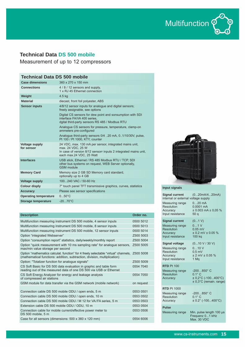
Technical Data DS 500 mobileMeasurement of up to 12 compressors
Technical Data DS 500 mobileCase dimensions 360 x 270 x 150 mm Connections 4 / 8 / 12 sensors and supply, 1 x RJ 45 Ethernet connection Weight 4.5 kgMaterial diecast, front foil polyester, ABSSensor inputs 4/8/12 sensor inputs for analogue and digital sensors; freely assignable, see options Digital CS sensors for dew point and sonsumption with SDI interface FA/VA 400 series, dgital third-party sensors RS 485 / Modbus RTU Analogue CS sensors for pressure, temperature, clamp-on ammeters pre-configured Analogue third-party sensors 0/4 ..20 mA, 0..1/10/30V, pulse, Pt 100 / Pt 1000, KTY, counterVoltage supply 24 VDC, max. 130 mA per sensor, integrated mains unit, for sensor max. 24 VDC, 25 W In case of version 8/12 sensorr inputs 2 integrated mains unit, each max.24 VDC, 25 Watt Interfaces USB stick, Ethernet / RS 485 Modbus RTU / TCP, SDI other bus systems on request, WEB Server optionally, GSM moduleMemory Card Memory size 2 GB SD Memory card standard, optionally up to 4 GBVoltage supply 100...240 VAC / 50-60 HzColour disply 7" touch panel TFT transmissive graphics, curves, statisticsAccuracy Please see sensor specificationsOperating temperature 0...50°CStorage temperature -20...70°C
GESCHÄFTSSTELLE SÜDCS INSTRUMENTS GMBHZindelsteiner Straße 1578052 VS-TannheimTel. +49 (0) 7705 978 99-0Fax +49 (0) 7705 978 [email protected]
Anwendungstechnische Merkmale der Verbrauchszähler VA 420:
Description Order no.
Multifunction measuring instrument DS 500 mobile, 4 sensor inputs 0500 5012Multifunction measuring instrument DS 500 mobile, 8 sensor inputs 0500 5013Multifunction measuring instrument DS 500 mobile, 12 sensor inputs 0500 5014 Option “integrated Webserver” Z500 5003Option “consumption report” statistics, daily/weekly/monthly report Z500 5004Option “quick measurement with 10 ms sampling rate” for analogue sensors, Z500 5005max/min value storage per secondOption “mathematics calculat. function” for 4 freely selectable “virtual” channels, Z500 5008(mathematical functions: addition, subtraction, division, multiplication) Option: "Totalizer function for analogue signals" Z500 5009CS Soft Basic for DS 500 data evaluation in graphic and table form 0554 7040 reading out of the measured data of one DS 500 via USB or EthernetCS Soft Energy Analyzer for energy and leakage analysis 0554 7050 of compressed air stationsGSM module for data transfer via the GSM network (mobile network) on request
Connection cable DS 500 mobile ODU / open ends, 5 m 0553 0501Connection cable DS 500 mobile ODU / open ends, 10 m 0553 0502Connection cable DS 500 mobile ODU / M 12 for VA/FA series, 5 m 0553 0503Extension cable DS 500 mobile ODU / ODU, 10 m 0553 0504Connection cable for mobile current/effective power meter to 0553 0506DS 500 mobile, 5 m Case for all sensors (dimensions: 500 x 360 x 120 mm) 0554 6006
Input signals
Signal current (0...20mA/4...20mA) internal or external voltage supplyMeasuring range 0…20 mAResolution 0.0001 mAAccuracy ± 0.003 mA ± 0,05 %Input resistance 50 q
Signal current (0...1 V)Measuring range 0…1 VResolution 0.05 mV Accuracy ± 0.2 mV ± 0.05 %Input resistance 100 kq
Signal voltage (0...10 V / 30 V)Measuring range 0…10 VResolution 0.5 mV Accuracy ± 2 mV ± 0.05 %Input resistance 1 Mq
RTD Pt 100Measuring range -200…850° CResolution 0.1° C Accuracy ± 0,2°C (-100...400°C) ± 0,3°C (remain. range)
RTD Pt 1000Measuring range -200…850° CResolution 0.1° C Accuracy ± 0.2° (-100...400°C)
Pulse Measuring range Min. pulse length 100 μs Frequenz 0...1 kHz Max. 30 VDC

16 www.cs-instruments.com
Multifunction
Multifunction measuring instruments DS 500 mobile energy analysis to DIN EN ISO 50001

www.cs-instruments.com 17
- Mobile current/effective power meters with 32 A CEE socket and plug for small machines and plants
- Easily to join up into the current circuit by means of an extension cable with 32 A CEE plug
- Measures KW, kWh, cos phi, kVar, kVA
- Data transfer to DS 500 mobile via Modbus
- CS PM 600 Mobile current/effective power meters with external current transform. for big machines and plants
- External current transformers for clamping around the phases (100 A oder 600 A)
- External magnetic measuring tips for measuring the voltage
- Measures KW, kWh, cos phi, kVar, kVA
- Data transfer to DS 500 mobile via Modbus
Multifunction

18 www.cs-instruments.com
Multifunction

www.cs-instruments.com 19
Multifunction

20 www.cs-instruments.com
Multifunction
Suitable probes from the CS Instrumentsproduct rangeConsumption sensors VA 400: Order no.
VA 400 consumption sensor, max.version (185 m/s), 0695 1122sensor length 220 mm including 5 m connection cable to DS 500 mobile VA 400 consumption sensor, high speed version (224 m/s), 0695 1123sensor length 220 mm, including 5 m connection cable to DS 500 mobile
Option for VA 400:Sensor length 120 mm ZSL 0120Sensor length 160 mm ZSL 0160Sensor length 300 mm ZSL 0300Sensor length 400 mm ZSL 0400
Consumption counters VA 420 with integrated measuring section:
Consumption counter VA 420 0.8... 90 l/min (R1/4” DN 8) 0695 0420Consumption counter VA 420 0.2... 90 m3/h (R1/2” DN 15) 0695 0421Consumption counter VA 420 0.3... 170 m3/h (R3/4” DN 20) 0695 0422Consumption counter VA 420 0.5... 290 m3/h (R1” DN 25) 0695 0423Consumption counter VA 420 0.7... 480 m3/h (R11/4” DN 32) 0695 0426Consumption counter VA 420 1.0... 550 m3/h (R11/2” DN 40) 0695 0424Consumption counter VA 420 2.0... 900 m3/h (R2” DN 50) 0695 0425
engraveddepth scale
locking ring
installation depth = x + y
dA = external diameter
x =
y
�
�
�
� �
�
x
d A
dA2
Consumption
Consumption
Flow measuring ranges VA 400 for compressed Air (ISO 1217: 1000 mbar, 20°C) Inner diameter of pipe VA 400 Max. VA 400 HighSpeed (185.0 m/s) (224.0 m/s)
Inch mm Meas. ranges Meas. ranges from ... to from ... to1/2” 16.1 DN 15 3.5... 1516 l/min 6.0... 1836 l/min3/4” 21.7 DN 20 0.4... 178 m3/h 0.7... 215 m3/h1” 27.3 DN 25 0.6... 295 m3/h 1.1... 357 m3/h1 1/4” 36.0 DN 32 1.2... 531 m3/h 2.5... 644 m3/h1 1/2” 41.8 DN 40 1.5... 728 m3/h 3.0... 882 m3/h2” 53.1 DN 50 2.5... 1198 m3/h 4.6... 1450 m3/h2 1/2” 71.1 DN 65 5... 2187 m3/h 7... 2648 m3/h3” 84.9 DN 80 7... 3133 m3/h 12... 3794 m3/h4” 110.0 DN 100 12... 5279 m3/h 16... 6391 m3/h5” 133.7 DN 125 18... 7808 m3/h 24... 9453 m3/h6” 159.3 DN 150 25... 11097 m3/h 43... 13436 m3/h8” 200.0 DN 200 33... 17533 m3/h 50... 21230 m3/h10” 250.0 DN 250 52... 27429 m3/h 80... 33211 m3/h12” 300.0 DN 300 80... 39544 m3/h 100... 47881 m3/h
Dew point sensors:
FA 410 dew point sensor, -80...20°Ctd including mobile 0699 1411 measuring chamber and 5 m connection cable to DS 500 mobileFA 415 dew point sensor, -20...50°Ctd including mobile 0699 1415measuring chamber and 5 m connection cable to DS 500 mobile
Extension cable, 10 m 0553 0504
Calibration certificates for consumption / dew point sensors:5 point precision calibration for consumption sensors including ISO certificate 3200 0001
Precision calibration at -40 °Ctd including ISO certificate 0699 3396
Dew point
Multifunction
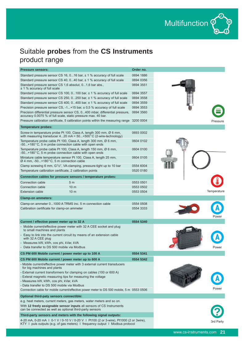
Suitable probes from the CS Instrumentsproduct range
Pressure
Power
Power
Power
3rd Party
Temperature
Pressure sensors: Order no.
Standard pressure sensor CS 16, 0...16 bar, ± 1 % accuracy of full scale 0694 1886 Standard pressure sensor CS 40, 0...40 bar, ± 1 % accuracy of full scale 0694 0356 Standard pressure sensor CS 1,6 absolut, 0...1,6 bar abs., 0694 3551 ± 1 % accuracy of full scaleStandard pressure sensor CS 100, 0...100 bar, ± 1 % accuracy of full scale 0694 3557 Standard pressure sensor CS 250, 0...250 bar, ± 1 % accuracy of full scale 0694 3558 Standard pressure sensor CS 400, 0...400 bar, ± 1 % accuracy of full scale 0694 3559Precision pressure sensor CS, -1...+15 bar, ± 0,5 % accuracy of full scale 0694 3553Precision differential pressure sensor CS, 0...400 mbar, differential pressure, 0694 3560accuracy 0.0075 % of full scale, static pressure max. 40 bar.Pressure calibration certificate, 5 calibration points within the measuring range 3200 0004
Temperature probes:
Screw-in temperature probe Pt 100, Class A, length 300 mm, Ø 6 mm, 0693 0002with measuring transducer 4...20 mA = 50...+500°C (2-wire-technology)Temperature probe cable Pt 100, Class A, length 300 mm, Ø 6 mm, 0604 0102-50...+180°C, 5 m probe connection cable with open endsTemperature probe cable Pt 100, Class A, length 150 mm, Ø 6 mm, 0604 0100-50...+180°C, 5 m probe connection cable with open endsMiniature cable temperature sensor Pt 100, Class A, length 25 mm, 0604 0105Ø 4 mm, -50...+180°C, 5 m connection cableClamp screwing 6 mm, G1/2”, VA-clamping, pressure-tight up to 10 bar 0554 6004Temperature calibration certificate, 2 calibration points 0520 0180
Connection cables for pressure sensors / temperature probes:
Connection cable 5 m 0553 0501Connection cable 10 m 0553 0502Extension cable 10 m 0553 0504
Clamp-on ammeters:
Clamp-on ammeter 0...1000 A TRMS inc. 5 m connection cable 0554 0508Calibration certificate for clamp-on ammeter 0554 3333
Current / effective power meter up to 32 A 0554 5340- Mobile current/effective power meter with 32 A CEE socket and plug to small machines and plants- Easy to link into the current circuit by means of an extension cable with 32 A CEE plug- Measures kW, kWh, cos phi, kVar, kVA- Data transfer to DS 500 mobile via Modbus
CS PM 600 Mobile current / power meter up to 100 A 0554 5341
CS PM 600 Mobile current / power meter up to 600 A 0554 5342- Mobile current/effective power meter with 3 external current transducers for big machines and plants- External current transformers for clamping on cables (100 or 600 A)- Exteral magnetic measuring tips for measuring the voltage- Measures kW, kWh, cos phi, kVar, kVA- Data transfer to DS 500 mobile via ModbusConnection cable for mobile current/effective power meter to DS 500 mobile, 5 m 0553 0506
Optional third-paty sensors connectible:e.g. heat meters, current meters, gas meters, water meters and so on.With 12 freely assignable sensor inputs all sensors of CS Instrumentscan be connected as well as optional third-party sensors
Third-party sensors and meters with the following signal outputs:4-20 mA, 0-20 mA I 0-1 V / 0-10 V / 0-20 V I Pt100 (2 or 3-wire), Pt1000 (2 or 3wire),KTY I puls outputs (e.g. of gas meters) I frequency output I Modbus protocol
?21www.cs-instruments.com

22 www.cs-instruments.com
Multifunction
CS PM 600 Mobile current/effective power meter suitable for DS 500 mobile
Special advantages:� Magnetic voltage measuring tips for measuring the voltage during operation.
� Hinged current transformers encompass the conductors of the phases L1, L2, L3. This can also be done during operation.
Anwendungstechnische Merkmale der Verbrauchszähler VA 420:
Description Order no.
CS PM 600 current/effective power meter up to 100 A 0554 5341
CS PM 600 current/effective power meter up to 600 A 0554 5342
- Mobile current effective power meter with 3 external current transformers for big machines and plants- External current transformers for clamping around the phases (100 A or 600 A)- External magnetic measuring tip for measuring the voltage- measures kW, kWh, cos phi, kVar, kVA- Data transfer to DS 500 mobile via Modbus
Connection cable for mobile current/effective power meter to DS 500 mobile, 5 m 0553 0506
Technical data:Parameters: Voltage (Volt) Current (Ampere) Cos phi Active power (kW) Apparent power (kVA) Reactive power (kVar) Active energy (kWh) Supply frequency (Hz) All parameters are transferred digitally to DS 500 mobile.
Accuracy current Threshold values for cur-measurement: rent deviation. Loss angle according to IEC 60044-1. Current deviation in % at rated current in
120 % 1 100 % 1 20 % 1.5 5 % 3
Accuracyactive energy: IEC 62053-21 Class 1
Sensor 3 x current transformers connections: (L1, L2, L3) 4 x voltage measurement (L1, L2, L3, N)
Interfaces: RS 485 (Modbus protocol)
Meas. range: Voltage measurement max. 400 Volt Current measurement max. 100 A resp. 600 A
Size current 100 A / 1 A transformer: (max. 24 mm conductor) 600 A / 1 A (max. 36 mm conductor)
Dimensions 270 x 225 x 156 mm case: (W x H x D)
Operatingtemperature: -10…+40°C
Magnetic voltage measuring tips
electrically isolated
Example: Measurement at a compressor
Measures voltage, current and calculates:Active power [kW]Apparent power [kVA]Reactive power [kVar]Active energy [kWh]cos phi
All measured data are transferred digitally (Modbus) to DS 500 mobile and can be recorded there.
Hinged current transformers

Multifunction
www.cs-instruments.com 23
CS PM 710 Current/effective power meter for panel mounting
Anwendungstechnische Merkmale der Verbrauchszähler VA 420:
Description Order no.
CS PM 710 CS PM 710 current/effective power meter for panel mounting, 0554 5343current transformer from 100 A to 2000 A connectible Current transformer 100/5 A connectible to current/effective power 0554 5344meter for panel mounting (for cabels up to Ø 21 mm) Current transformer 200/5 A connectible to current/effective power 0554 5345meter for panel mounting (for cabels up to Ø 21 mm) Current transformer 300/5 A connectible to current/effective power 0554 5346meter for panel mounting (for cabels up to Ø 22 mm) Current transformer 500/5 A connectible to current/effective power 0554 5347meter for panel mounting (for cabels up to Ø 22 mm) Current transformer 600/5 A connectible to current/effective power 0554 5348meter for panel mounting (for cabels up to Ø 22 mm) Current transformer 1000/5 A connectible to current/effective power 0554 5349meter for panel mounting (for current bar up to 65 x 32 mm) Current transformer 2000/5 A connectible to current/effective power 0554 5350meter for panel mounting (for current bar up to 127 x 38 mm) Connection cable to DS 500 mobile, 5 m, with open ends 0553 0501Connection cable to DS 500 mobile, 10 m, with open ends 0553 0502
All measured data are transferred digitally (Modbus) to DS 500 mobile and can be recorded there.
Measures voltage, current and calculates:Active power [kW]Apparent power [kVA]Reactive power [kVar]Active energy [kWh]cos phi
Technical Data:Parameters: Voltage (Volt) Current (Ampere) Cos phi Active power (kW) Apparent power (kVA) Reactive power (kVar) Active energy (kWh) Supply frequency (Hz) All parameters are transferred digitally to DS 500 mobile.
Accuracy current measurement: ± 0,5% of 1 to 6 A
Accuracy ± 0,5% of voltage: 50 V to 277 V
Accuracyactive energy: IEC 62053-21 Class 1
Interfaces: RS 485 (Modbus protocol)
Measuring Voltage measurement range: max. 480 Volt
Dimensions: 96 x 96 x 69 mm (W x H x D)
Operatingtemperature: -5…+55°C
L1
L2
L3
N Current
transformers
Digital data transfer to DS 500 mobile
via RS 485 - Modbus
Voltage measurement

24 www.cs-instruments.com
Dew point
Typical procedure of compressed air drying with dew point measurement
SUMMER:25°C80%RH23.05g/m³
H2O =23.05 x 10 x 0.8 =184.4g
10m³1bar
Compressor 1m³10bar
80-160°CH2O =184.4g
Cooling agent0°C
5°Ctdf max = 6.8g/m³
184,4g/m³- 6.8g/m³
177.6g
Condensate
Dryer(Dew point -50°Ctd)f max = 0.038g/m³
20°CH2O =0.038g
1m³10bar
5°CH2O =6.8g
1m³
10bar0.038g/m³
0.038 x 100%= 0.21%RH17.3 Compressed air
6.8g/m³ - 0.038g/m³ =
6.762g
Condensate
DP 300FA 415FA 416DP 300
FA 410FA 400
Regene-ration airU
SE
R
SUMMER

Technical data DP 300
Display single line: dew point (°Ctd resp. °F) relative humidity (% RH) temperature (°C resp. °F) freely selectable
Display functions: Max, Min, state of battery
Measuring range: -80...50°Ctd -20...70°C 0 to 100 % RH
Pressure range: -1 to 50 bar standard -1 to 350 bar high-pressure version
PC connection: SDI interface
Accuracy: ± 0,5°Ctd at -10...50°Ctd typical ± 2°Ctd at -40°CtdPower supply: internal rech. batteries (4 x 1,5 NiMh AAA) for approx. 15 h continuous operation
Operating temp: -20...70°C
EMC: DIN EN 61326
Screw-in thread: G 1/2" stainless steel
Housing: polycarbonate
www.cs-instruments.com 25
Dew point
Description Order no. Set DP 300 consisting of: 0600 6000Portable dew point meter DP300 up to 50 bar incl. rechargeable battery 0560 6000Mobile measuring chamber up to 16 bar 0699 4490Diffusion-tight teflon hose 1 m with fast coupling at both ends 0554 0003 Power supply 24 VDC, 230 VAC for rech. battery load and long-term meas. 0554 0001Control and calibration set 11.3 % RH 0554 0002Quick-lock coupling 0530 1101Dry container for DP 300 0699 2500Transport case 0554 6002
Additional accessories, not included in the set:Portable dew point meter DP 300 up to 350 bar including rech. battery 0560 6001High-pressure measuring chamber up to 350 bar 0699 3590Precision calibration at -40°Ctd with ISO certificate 0699 3396Measuring chamber for atmospheric dew point 0699 3690 Measuring chamber for granulate dryers for minimum over pressure 0699 3490Measuring chamber for respiratory air bottles up to 350 bar 0699 3790 Control and calibration set 33 % RH 0554 0004Control and calibration set 75.3 % RH 0554 0005
Special feature� Large measuring range to -80 °Ctd for all dryers (adsorption, membrane, refrigeration dryers)
Portable dew point meter DP 300Relative humidity, temperature and dew point measurement with one instrument
The portable dew point meter DP 300 is the ideal instrument for service and is supplied in a convenient case.Thanks to the internal rechargeable battery it measures quickly and reliably for a duration of up to 15 hours.

26 www.cs-instruments.com
Dew point
FA 410 from -80 to 20°Ctd
FA 410 – the ideal dew point sensor for monitoring membrane and adsorption dryers
Typical use in compressed air dryers/granulate dryers at very low dew points down to -80°C.
Special features� Measuring range -80...20 °Ctd� Extremely long-term stable � Analogue output 4...20 mA� Condensation insensitive� Quick response time � Pressure-tight up to 350 bar (special version)
Recommendation:
Mounting with standard measuring chamber for compressed air up to 16 bar Advantage: Easy installation via fast coupling.
Description Order no.. FA 410 dew point sensor, -80°...20°Ctd incl. inspection certificate 0699 0410FA 410 dew point sensor, -20°...50°Ctd incl. inspection certificate 0699 0412
Connection cables:Connection cable, length: 5 m 0553 0104Connection cable, length: 10 m 0553 0105
Options for FA 410:Option special version up to 350 bar 0699 4003Option output in mg/m3, g/kg, oder %RH, special scaling 4...20 mA 0699 4004
Additional accessories:Standard measuring chamber up to 16 bar 0699 3390High-pressure measuring chamber up to 350 bar 0699 3590Measuring chamber for respiratory air bottles up to 350 bar 0699 3790 CS Service Software for FA/VA 400 sensors including PC connection set, 0554 2005 USB adapter and interface adapter to the sensor as well as CSM-S for data recording, please see page 21Mains unit in wall housing 100-240 V, 10 VA, 50-60 Hz/24 VDC, 0.35 A 0554 0108 Mains unit on DIN rail 100-240 VAC / 24 VDC, 0.35 A 0699 3340
Calibration:Precision calibration at -40°Ctd including ISO certificate 0699 3396Precision calibration at 3°Ctd including ISO certificate 3200 0003Control and calibration set 11.3 % RH 0554 0002Control and calibration set 33 % RH 0554 0004Control and calibration set 75.3 % RH 0554 0005
Technical data FA 410
Measuring range: -80...20°Ctd resp. -20...50°CtdAccuracy: ± 1°C at 20...-20°Ctd ± 2°C at -20...-50°Ctd ± 3°C at -50...-80°CtdPressure range: -1...50 bar special version up to 350 bar
Power supply: 24 VDC (16...30 VDC)
Protection class: IP 65
EMC: according to DIN EN 61326
Operating temp: -20...70 °C
Connection: M12, 5-pole
PC connection: SDI interface
Analogue output: 4...20 mA = -80...20°Ctd resp. 4...20 mA = -20...50°CtdBurden foranalogue output: < 500 Ohm
Screw-in thread: G1/2”
Dimensions: Ø 30 mm, length approx. 130 mm Via service software:– choose units: % RH, °Ctd, g/m3, mg/m3, ppm V/V– scaling change 4...20 mA
Special version: 4...20mA, 2-wire technology
www.cs-instruments.com 27
Dew point
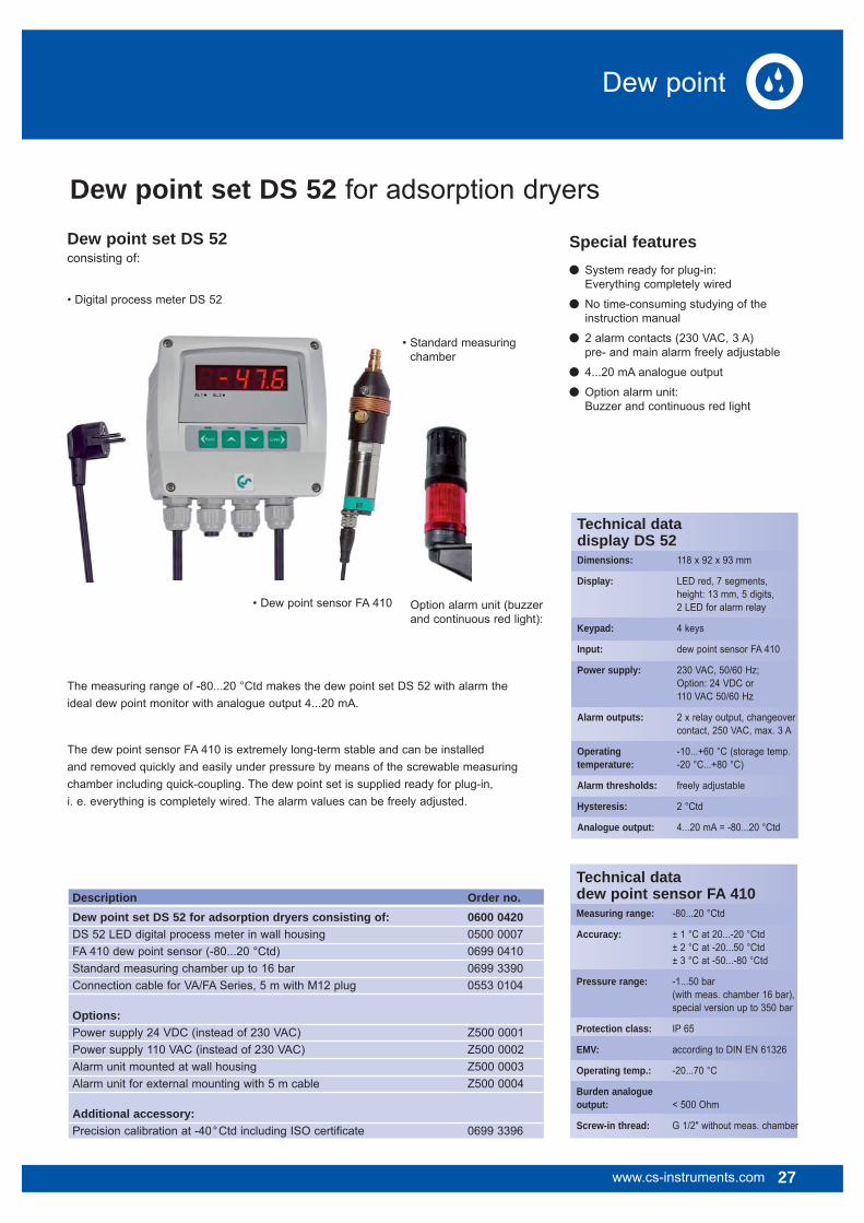
Dew point set DS 52 for adsorption dryersDew point set DS 52consisting of:
• Digital process meter DS 52
• Dew point sensor FA 410
• Standard measuring • • chamber
The measuring range of -80...20 °Ctd makes the dew point set DS 52 with alarm the ideal dew point monitor with analogue output 4...20 mA.
The dew point sensor FA 410 is extremely long-term stable and can be installed and removed quickly and easily under pressure by means of the screwable measuring chamber including quick-coupling. The dew point set is supplied ready for plug-in, i. e. everything is completely wired. The alarm values can be freely adjusted.
Description Order no.Dew point set DS 52 for adsorption dryers consisting of: 0600 0420DS 52 LED digital process meter in wall housing 0500 0007FA 410 dew point sensor (-80...20 °Ctd) 0699 0410Standard measuring chamber up to 16 bar 0699 3390Connection cable for VA/FA Series, 5 m with M12 plug 0553 0104
Options:Power supply 24 VDC (instead of 230 VAC) Z500 0001Power supply 110 VAC (instead of 230 VAC) Z500 0002Alarm unit mounted at wall housing Z500 0003Alarm unit for external mounting with 5 m cable Z500 0004
Additional accessory:Precision calibration at -40°Ctd including ISO certificate 0699 3396
Special features� System ready for plug-in: Everything completely wired
� No time-consuming studying of the instruction manual
� 2 alarm contacts (230 VAC, 3 A) pre- and main alarm freely adjustable
� 4...20 mA analogue output
� Option alarm unit: Buzzer and continuous red light
Technical data dew point sensor FA 410Measuring range: -80...20 °Ctd
Accuracy: ± 1 °C at 20...-20 °Ctd ± 2 °C at -20...50 °Ctd ± 3 °C at -50...-80 °Ctd
Pressure range: -1...50 bar (with meas. chamber 16 bar), special version up to 350 bar
Protection class: IP 65
EMV: according to DIN EN 61326
Operating temp.: -20...70 °C
Burden analogue output: < 500 Ohm
Screw-in thread: G 1/2" without meas. chamber
Technical data display DS 52Dimensions: 118 x 92 x 93 mm
Display: LED red, 7 segments, height: 13 mm, 5 digits, 2 LED for alarm relay
Keypad: 4 keys
Input: dew point sensor FA 410
Power supply: 230 VAC, 50/60 Hz; Option: 24 VDC or 110 VAC 50/60 Hz
Alarm outputs: 2 x relay output, changeover contact, 250 VAC, max. 3 A
Operating -10...+60 °C (storage temp.temperature: -20 °C...+80 °C)
Alarm thresholds: freely adjustable
Hysteresis: 2 °Ctd
Analogue output: 4...20 mA = -80...20 °Ctd
Option alarm unit (buzzer and continuous red light):
FA 415 / FA 416 from -20 to 50°Ctd
The dew point sensors FA 415/416 for the typical use in refrigeration dryers
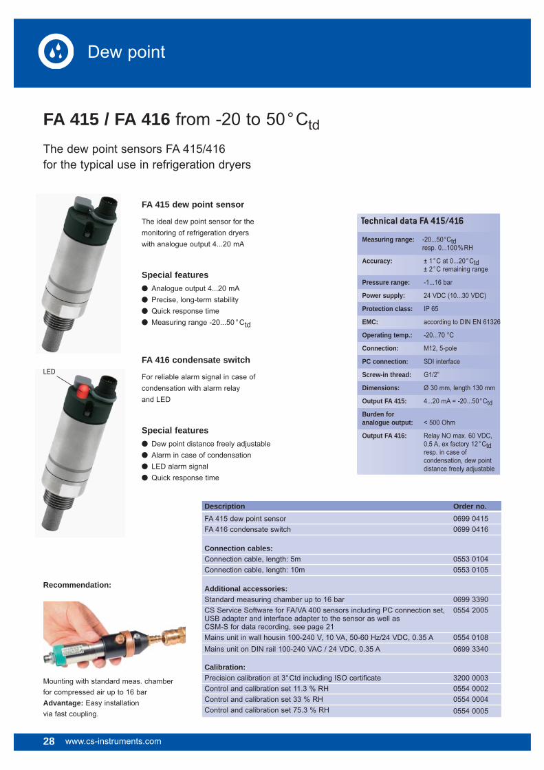
FA 415 dew point sensor
The ideal dew point sensor for the monitoring of refrigeration dryerswith analogue output 4...20 mA
Special features� Analogue output 4...20 mA� Precise, long-term stability� Quick response time� Measuring range -20...50 °Ctd
28 www.cs-instruments.com
Dew point
FA 416 condensate switch
For reliable alarm signal in case ofcondensation with alarm relayand LED
Special features� Dew point distance freely adjustable� Alarm in case of condensation� LED alarm signal� Quick response time
Description Order no. FA 415 dew point sensor 0699 0415FA 416 condensate switch 0699 0416
Connection cables:Connection cable, length: 5m 0553 0104Connection cable, length: 10m 0553 0105
Additional accessories:Standard measuring chamber up to 16 bar 0699 3390CS Service Software for FA/VA 400 sensors including PC connection set, 0554 2005 USB adapter and interface adapter to the sensor as well as CSM-S for data recording, see page 21Mains unit in wall housin 100-240 V, 10 VA, 50-60 Hz/24 VDC, 0.35 A 0554 0108Mains unit on DIN rail 100-240 VAC / 24 VDC, 0.35 A 0699 3340
Calibration:Precision calibration at 3°Ctd including ISO certificate 3200 0003Control and calibration set 11.3 % RH 0554 0002Control and calibration set 33 % RH 0554 0004Control and calibration set 75.3 % RH 0554 0005
LED
Recommendation:
Mounting with standard meas. chamber for compressed air up to 16 bar Advantage: Easy installation via fast coupling.
Technical data FA 415/416
Measuring range: -20...50°Ctd resp. 0...100%RH
Accuracy: ± 1°C at 0...20°Ctd ± 2°C remaining range
Pressure range: -1...16 bar
Power supply: 24 VDC (10...30 VDC)
Protection class: IP 65
EMC: according to DIN EN 61326
Operating temp.: -20...70 °C
Connection: M12, 5-pole
PC connection: SDI interface
Screw-in thread: G1/2”
Dimensions: Ø 30 mm, length 130 mm
Output FA 415: 4...20 mA = -20...50°CtdBurden for analogue output: < 500 Ohm
Output FA 416: Relay NO max. 60 VDC, 0,5 A, ex factory 12°Ctd resp. in case of condensation, dew point distance freely adjustable

www.cs-instruments.com 29
Dew point
Dew point set DS 52consisting of:
Special features� System ready for plug-in Everything completely wired
� No time-consuming studying of the instruction manual
� 2 alarm contacts (230 VAC, 3 A) pre- and main-alarm freely adjustable
� 4...20 mA analogue output
� Option alarm unit: Buzzer and continuous red light
The measuring range of -20...50 °Ctd makes the dew point set DS 52 with alarm the ideal dew point monitor with analogue output 4...20 mA.
The dew point sensor FA 415 is extremely long-term stable and can be installed and removed quickly and easily under pressure by means of the screwable measuring chamber including quick coupling. The dew point set is supplied ready for plug-in, i. e. everything is completely wired. The alarm values can be freely adjusted.
Description Order no. Dew point set DS 52 for refrigeration dryers, consisting of: 0600 0425DS 52 LED digital process meter in wall housing 0500 0008FA 415 dew point sensor (-20...50 °Ctd) 0699 0415Standard measuring chamber up to 16 bar 0699 3390Connection cable for VA/FA Series, 5 m with M12 plug 0553 0104
Options:Power supply 24 VDC (instead of 230 VAC) Z500 0001Power uspply 110 VAC (instead of 230 VAC) Z500 0002Alarm unit mounted at wall housing Z500 0003Alarm unit for external mounting with 5 m lead Z500 0004
Additional accessory:Precision calibration at 3°Ctd including ISO certificate 3200 0003
Technical data dew point sensor FA 415Measuring range: -20...50 °Ctd
Accuracy: ± 1 °C at 0...20 °Ctd ± 2 °C remaining range
Pressure range: -1...16 bar
Protection class: IP 65
EMV: according to DIN EN 61326
Operating temp.: -20...70 °C
Connection: M12, 5 pole
PC connection: SDI interface
Burden analogue output: < 500 Ohm
Screw-in thread: G 1/2" without meas.chamber
Technical data display DS 52Dimensions: 118 x 92 x 93 mm
Display: LED red, 7 segments, height: 13 mm, 5 digits, 2 LED for alarm relay
Keypad: 4 keys
Input: dew point sensor FA 415
Power supply: 230 VAC, 50/60 Hz; Option: 24 VDC or 110 VAC 50/60 Hz
Alarm outputs: 2 x relay output, changeover contact, 250 VAC, max. 3 A
Operating -10...+60 °C (storage temp.temperature: -20 °C...+80 °C)
Alarm thresholds: freely adjustable
Hysteresis: 2 °Ctd
Analogue output: 4...20 mA = -20...50 °Ctd
• Digital process meter DS 52
• Dew point sensor FA 415
• Standard measuring • • chamber
Option: Alarm unit (buzzer and continuous red light)
Dew point set DS 52 for refrigeration dryers

Option: Alarm unit(buzzer and continuous red light)
• 2nd sensor input for • • dew point or • consumption • sensors VA 400/420
• Standard measuring chamber
Special features
� System ready for plug-in: everything completely wired
� No time-consuming studying of the instruction manual
� 2 alarm contacts (230 VAC, 3 A) pre- and main-alarm freely adjustable
� 4...20 mA analogue output
� Optical alarm: Red flashing
� Parallel indication % RH, °C, °Ctd
Option: Integrated data logger
� Recording of dew point progression of up to 1 million measured values
� CSM-S for evaluation in graphic and table form including USB interface. Read-out of the data optionally by USB or ethernet.
Technical data DS 300Dimensions: 118 x 115 x 93 mm, IP 65 (wall housing) 92 x 92 x 70 mm, IP 65 (panel mounting)
Inputs: 2 digital inputs for FA 410 resp. VA 400
Interface: USB
Keypad: 4 keys
Power supply: 100...240 VAC, 50-60 Hz
Acccuracy: see FA 410 page 6
Alarm outputs: 2 relays, 230 VAC, 3 A
Operating temp.: 0...50 °C
Transport -20...70 °Ctemperature:
OPTIONS
Data logger: 1 million meas. values start/stop time, meas. rate freely adjustable
Description Order no. Dew point set FA 410 for adsorption dryers (-80...20°Ctd) 0600 0410Dew point set FA 410 for refrigeration dryers (-20...50°Ctd) 0600 0412Option:Integrated data logger for 1 million measured values Z500 3001Ethernet interface Z500 3005Alarm unit mounted at wall housing Z500 0003Alarm unit for external mounting with 5 m cable Z500 0004
Additional accessories:CSM-S for data evaluation in graphic and table form 0554 7011 including USB interfacePrecision calibration at -40°Ctd including ISO certificate 0699 3396Precision calibration at 3°Ctd including ISO certificate 3200 0003Control and calibration set 11.3 % RH 0554 0002Control and calibration set 33 % RH 0554 0004Control and calibration set 75.3 % RH 0554 0005
Dew point set FA 410Ready for upgrading with data logger,ethernet interface and 2nd sensor input
Dew point set FA 410consisting of:
Dew point
30 www.cs-instruments.com
• Multifunction measuring• instrument DS 300
• Optional: • Ethernet • interface
� �
• Dew point sensor •• FA 410

www.cs-instruments.com 31
Dew point
FA 400 from -80 to 20°Ctd
FA 400 is the ideal dew point measuring instrument with integrated display and alarm relay for refrigeration, membrane and adsorption dryers
It replaces the worldwide proven instrument FA 200. The threshold value can be easily adjusted via the keypad.
Technical data FA 400Measuring range: -80...20°Ctd, -60...30°Ctd, -20...50°Ctd resp. 0...100%RH
Accuracy: ± 1°C at 20...-20°Ctd ± 2°C at -20...-50°Ctd ± 3°C at -50...-80°Ctd
Pressure range: -1...50 bar special version up to 350 bar
Power supply: 24 VDC (16...30 VDC) smoothed
Protection class: IP 65
EMV: according to DIN EN 61326
Operating temp.: -20...50°C
Connection: 2 x M12, 5-pole for analogue output and alarm output
PC connection: SDI interface
Output: 4...20 mA = -80...20°Ctd 4...20 mA = -60...30°Ctd 4...20 mA = -20...50°Ctd
Burden for analogue output: < 500 Ohm
Alarm relay: NO, max. 60 VDC, 0.5 A
Screw-in thread: G1/2”
Dimensions: Ø 65 mm, length 160 mm
Output signals % RH, °Ctd, g/m3, mg/m3, via software: ppm V/V
Special features
� -80...20°Ctd� Integrated display
� Threshold value adjustable via keypad alarm relay (max. 60 VDC, 0.5 A)
� Pressure-tight up to 350 bar (special version)
� Extreme long-term stability
� Quick response time
� 4...20 mA analogue output
� 2 versions: Refrigeration dryers and adsorption dryers
Description Order no. FA 400 dew point sensor for refrigeration dryers, -20...50°Ctd 0699 0401FA 400 dew point sensor for adsorption dryers, -80...20°Ctd 0699 0402FA 400 dew point sensor, replacement of FA 200, -60...30°Ctd 0699 0403
Connection cables:Connection cable, length: 5m (power supply and analogue output) 0553 0104Connection cable, length 10m (power supply and analogue output) 0553 0105Alarm cable, length: 5m 0553 0106Alarm cable, length: 10m 0553 0107
Options for FA 400:Special version FA 400 up to 350 bar 0699 4003Special scaling, output in ppm V/V, % RH, mg/m3 0699 4004
Additional accessories:Standard measuring chamber up to 16 bar 0699 3390CS Service Software for FA/VA 400 sensors including PC connection set, 0554 2005 USB adapter and interface adapter to the sensor as well as CSM-S for data recording, see page 21Mains unit in wall housing 100-240 V, 10 VA, 50-60 Hz/24 VDC, 0.35 A 0554 0108 Power supply 100-240 VAC/24 VDC, 0.35 A for FA/VA 400 Series, 2 m cable 0554 0107
Calibration:Precision calibration at -40°Ctd including ISO certificate 0699 3396Precision calibration at 3°Ctd including ISO certificate 3200 0003Control and calibration set 11.3 % RH 0554 0002Control and calibration set 33 % RH 0554 0004Control and calibration set 75.3 % RH 0554 0005
Alarm adjustable via keypad
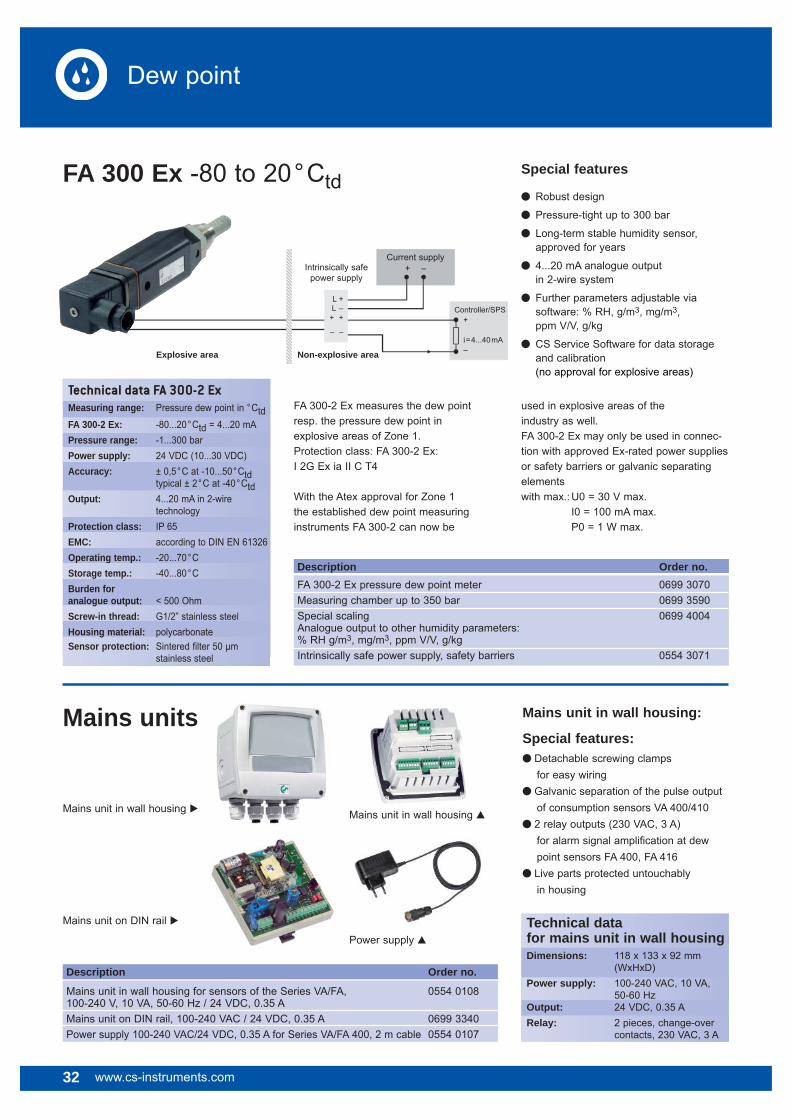
FA 300 Ex -80 to 20°Ctd
FA 300-2 Ex measures the dew point resp. the pressure dew point in explosive areas of Zone 1. Protection class: FA 300-2 Ex:I 2G Ex ia II C T4
With the Atex approval for Zone 1 the established dew point measuring instruments FA 300-2 can now be
used in explosive areas of the industry as well.FA 300-2 Ex may only be used in connec-tion with approved Ex-rated power supplies or safety barriers or galvanic separating elements with max.: U0 = 30 V max. I0 = 100 mA max. P0 = 1 W max.
32 www.cs-instruments.com
Dew point
Description Order no. FA 300-2 Ex pressure dew point meter 0699 3070Measuring chamber up to 350 bar 0699 3590Special scaling 0699 4004 Analogue output to other humidity parameters: % RH g/m3, mg/m3, ppm V/V, g/kgIntrinsically safe power supply, safety barriers 0554 3071
Special features
� Robust design
� Pressure-tight up to 300 bar
� Long-term stable humidity sensor, approved for years
� 4...20 mA analogue output in 2-wire system
� Further parameters adjustable via software: % RH, g/m3, mg/m3, ppm V/V, g/kg
� CS Service Software for data storage and calibration (no approval for explosive areas)
Explosive area Non-explosive area
Current supply+ –Intrinsically safe
power supply
L +L –
+ +
– –
Controller/SPS+
i=4...40mA–
Mains units
Description Order no.
Mains unit in wall housing for sensors of the Series VA/FA, 0554 0108100-240 V, 10 VA, 50-60 Hz / 24 VDC, 0.35 AMains unit on DIN rail, 100-240 VAC / 24 VDC, 0.35 A 0699 3340Power supply 100-240 VAC/24 VDC, 0.35 A for Series VA/FA 400, 2 m cable 0554 0107
Mains unit in wall housing � Mains unit in wall housing �
Power supply �
Mains unit on DIN rail � Technical data for mains unit in wall housingDimensions: 118 x 133 x 92 mm (WxHxD)Power supply: 100-240 VAC, 10 VA, 50-60 Hz Output: 24 VDC, 0.35 ARelay: 2 pieces, change-over contacts, 230 VAC, 3 A
Mains unit in wall housing:
Special features:� Detachable screwing clamps for easy wiring � Galvanic separation of the pulse output of consumption sensors VA 400/410� 2 relay outputs (230 VAC, 3 A) for alarm signal amplification at dew point sensors FA 400, FA 416� Live parts protected untouchably in housing
Technical data FA 300-2 ExMeasuring range: Pressure dew point in °CtdFA 300-2 Ex: -80...20°Ctd = 4...20 mAPressure range: -1...300 barPower supply: 24 VDC (10...30 VDC)Accuracy: ± 0,5°C at -10...50°Ctd typical ± 2°C at -40°CtdOutput: 4...20 mA in 2-wire technologyProtection class: IP 65EMC: according to DIN EN 61326Operating temp.: -20...70°CStorage temp.: -40...80°CBurden foranalogue output: < 500 OhmScrew-in thread: G1/2” stainless steelHousing material: polycarbonateSensor protection: Sintered fi lter 50 μm stainless steel

www.cs-instruments.com 33
Dew point
Accessories for dew point measurement and calibration
Standard measuringchamber for compressed air up to 16 barOrder no. 0699 3390
High-pressure measuring chamber for compressed air up to 350 bar*Order no. 0699 3590
Measuring chamber for granulate dryers up to 250 mbarOrder no. 0699 3490
Measuring chamber for atmosphericdew pointOrder no. 0699 3690
Measuring chamber for respiratory airbottles up to 350 bar*Order no. 0699 3790
* in case of pressures higher than 50 bar pleaseorder special version FA 400 / FA 410.
Mounting recommendation
The dew point meters can be mounted directly into the air stream.
However, we recommend always to use a screwable measuring chamber.
Screwable measuring chamber Advantage: Easy installation via fast coupling
The right measuring chamber for each measuring task:
CS Service Software
for FA/VA 400 sensors including PC connection set, USB adapter and interface adapter to the sensor as well as CSM-S for data recording.
The humidity sensors FA 400, FA 410, FA 415, FA 416 can be connected to the PC and the following adjustments can be carried out by means of the CS Service Software:
– Scaling of the 4...20 mA analogue output
– Selecting the units: % RH, °Ctd, g/m3, mg/m3, ppm V/V
– Reading out of: Version no., production date, serial no., date of last calibration
– Adjustment of the alarm limits
– Single-point calibration (adjustment) - for this purpose a reference measuring instrument is required
By means of the CSM-S the measured data can be read out online at the PC. It can be stored and evaluated in graphic and in table form.

34 www.cs-instruments.com
Dew point
Calibration ofdew point sensorsThe calibration range for dew pointsensors is -80...+20°Ctd
It is possible to calibrate dew point sensors of CS Instruments as well as of other manufacturers. High precision reference measuring instruments with DKD resp. BAM certificate grant an accuracy of up to 0.1°C dew point.
Control and calibration set
Control and calibration sets gurantee a defined humidity by means of a saturated saline solution.
The control and calibration set is screwed onto the dew point sensor and therefore enables an easy and low-priced possibilityfor on-site control and calibration down to -20°C dew point.
Calibration range: from -80 to 20°Ctd
Accuracy of the DKD reference: 0.1°Ctd
Special feature
� Due to the digital data transfer only the dew point sensor has to be calibrated, enabling the display unit DS 300 to stay on-site at all times.
Description Order no. Recalibration and precision calibration at -40 °Ctd including ISO certificate 0699 3333Precision calibration in the range -80...20 °Ctd, °Ctd points freely selectable 0700 7710Control and calibration set 11.3 % RH 0554 0002Control and calibration set 33 % RH 0554 0004Control and calibration set 75.3 % RH 0554 0005

www.cs-instruments.com 35
Consumption
Consumption and flowmeasurement
Cost savingIn Germany 60,000 compressed air plants use 14,000,000,000 kWh electrical energy per year. 15 to 20% could be easily saved(Peter Radgen, Fraunhofer Institut, Karlsruhe). Most of these costsare caused by leakages in the compressed air system. The air "escapes" unused. 1 leak with a diameter of 1 mm causes costsof approximately 270 EUR/year
The leak detector LD 300 (please see page 40) will be payed offafter 4 leakages
Cost distribution in compressed air systems:
Equipment
Maintenance
Electricity
Example for a calculation of leakage costs at different pressures:
Leak Ø Air loss at Air loss at Energy loss kWh Energy loss kWh Costs € p.a. Costs € p.a. (mm) 6 bar (l/s) 12 bar (l/s) at 6 bar at 12 bar at 6 bar at 12 bar
1 1.2 1.8 0.3 1.0 144 480
3 11.1 20.8 3.1 12.7 1,488 6,96
5 30.9 58.5 8.3 33.7 3,984 16,176
10 123.8 235.2 33.0 132.0 15,840 63,360
Source: www.druckluft.effizient.de
36 www.cs-instruments.com
Consumption
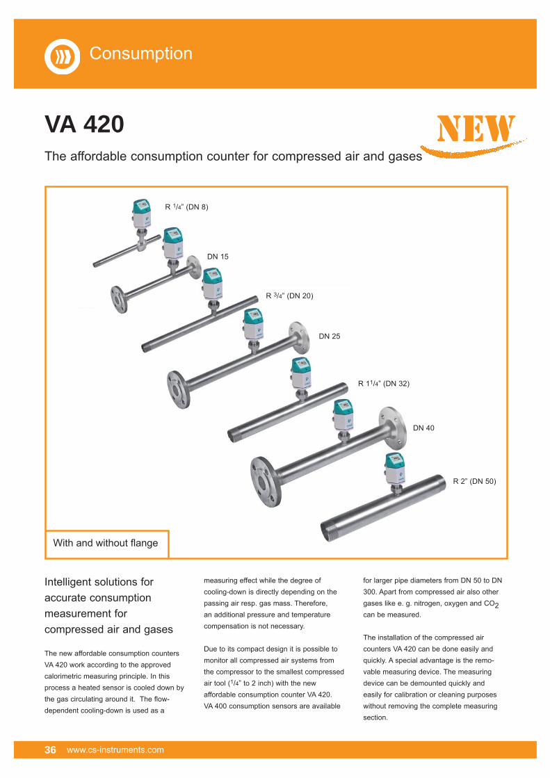
VA 420The affordable consumption counter for compressed air and gases
Intelligent solutions for accurate consumption measurement for compressed air and gases
The new affordable consumption counters VA 420 work according to the approved calorimetric measuring principle. In this process a heated sensor is cooled down by the gas circulating around it. The flow-dependent cooling-down is used as a
measuring effect while the degree of cooling-down is directly depending on the passing air resp. gas mass. Therefore, an additional pressure and temperature compensation is not necessary.
Due to its compact design it is possible to monitor all compressed air systems from the compressor to the smallest compressed air tool (1/4” to 2 inch) with the new affordable consumption counter VA 420. VA 400 consumption sensors are available
for larger pipe diameters from DN 50 to DN 300. Apart from compressed air also other gases like e. g. nitrogen, oxygen and CO2 can be measured.
The installation of the compressed air counters VA 420 can be done easily and quickly. A special advantage is the remo-vable measuring device. The measuring device can be demounted quickly and easily for calibration or cleaning purposes without removing the complete measuring section.
new
mit und ohne FlanschWith and without fl ange
R 1/4” (DN 8)
DN 15
R 3/4” (DN 20)
DN 25
R 11/4” (DN 32)
DN 40
R 2” (DN 50)
www.cs-instruments.com 37
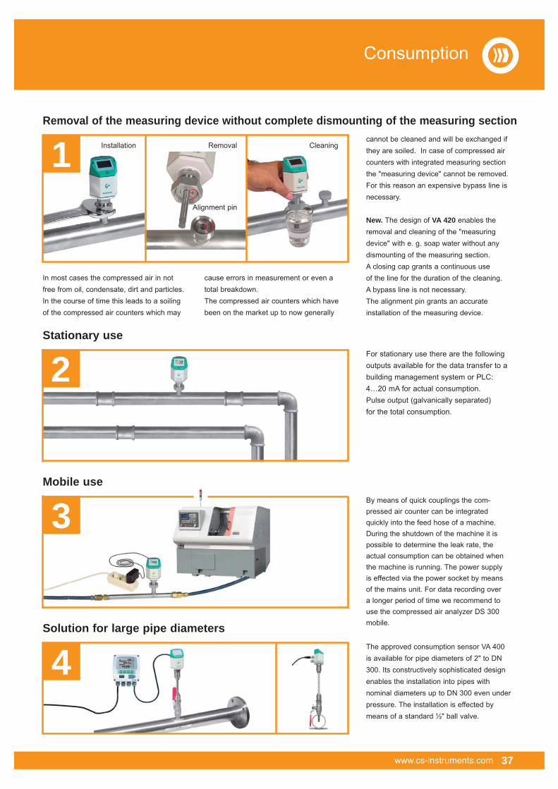
cannot be cleaned and will be exchanged if they are soiled. In case of compressed air counters with integrated measuring section the "measuring device" cannot be removed. For this reason an expensive bypass line is necessary.
New. The design of VA 420 enables the removal and cleaning of the "measuring device" with e. g. soap water without any dismounting of the measuring section. A closing cap grants a continuous use of the line for the duration of the cleaning. A bypass line is not necessary. The alignment pin grants an accurateinstallation of the measuring device.
The approved consumption sensor VA 400 is available for pipe diameters of 2" to DN 300. Its constructively sophisticated design enables the installation into pipes with nominal diameters up to DN 300 even under pressure. The installation is effected by means of a standard ½" ball valve.
By means of quick couplings the com-pressed air counter can be integrated quickly into the feed hose of a machine. During the shutdown of the machine it is possible to determine the leak rate, the actual consumption can be obtained when the machine is running. The power supply is effected via the power socket by means of the mains unit. For data recording over a longer period of time we recommend to use the compressed air analyzer DS 300 mobile.
For stationary use there are the following outputs available for the data transfer to a building management system or PLC: 4…20 mA for actual consumption.Pulse output (galvanically separated) for the total consumption.
Removal of the measuring device without complete dismounting of the measuring section
Stationary use
Solution for large pipe diameters
Mobile use
In most cases the compressed air in not free from oil, condensate, dirt and particles. In the course of time this leads to a soiling of the compressed air counters which may
cause errors in measurement or even a total breakdown.The compressed air counters which havebeen on the market up to now generally
Installation Removal
Alignment pin
Cleaning
Consumption
4
3
2
1
38 www.cs-instruments.com
Consumption
� Easy and affordable installation
� Units freely selectable via keypad m³/h, m³/min, l/min, l/s, kg/h, kg/min, kg/s, cfm
� Compressed air counter up to 1,999,999,999 m³. Resettable to "zero" via keypad
� Analogue output 4...20 mA, pulse output (galvanically separated)
� High measuring accuracy also in the lower measuring range (ideal for leakage measurement)
� Negligibly small loss of pressure
� Calorimetric measuring principle, no additional pressure and temperature measurement necessary, no mechanically moved parts
� Gas types adjustable via software (nitrogen, oxygen, CO2, nitrous oxide, argon)
� Compressed air balancing, com- pressed air consumption measurement
� Leakage air / leak rate determination
� Mobile compressed air measurement in front of single machines/plants
� Flow measurement of process gases like e. g. nitrogen, CO2, oxygen, argon, nitrous oxide
� Flow measurement at nitrogen generators
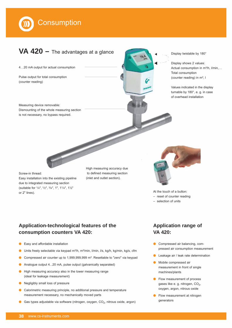
At the touch of a button:– reset of counter reading– selection of units
Application-technological features of the consumption counters VA 420:
Application range ofVA 420:
�
�
Display twistable by 180°
Display shows 2 values:Actual consumption in m³/h, l/min,…Total consumption (counter reading) in m³, l
Values indicated in the display turnable by 180°, e. g. in case of overhead installation
VA 420 – The advantages at a glance
4…20 mA output for actual consumption
Pulse output for total consumption (counter reading)
Measuring device removable:Dismounting of the whole measuring section is not necessary, no bypass required.
Screw-in thread:Easy installation into the existing pipeline due to integrated measuring section (suitable for 1/4", 1/2", 3/4", 1", 11/4", 1½" or 2" lines).
High measuring accuracy due to defined measuring section (inlet and outlet section).

www.cs-instruments.com 39
Consumption
Flow measuring ranges VA 420 for compressed air (ISO 1217: 1000 mbar, 20°C)
Connection Outer pipe Inner pipe Measuring range L L1 H H1 A thread dia. mm dia. mm from to mm mm mm mm mmR 1/4” 13.7 08.5 0.8 90 l/min 194 137 174.7 165.7 15 R 1/2” 21.3 16.1 0.2 90 m3/h 300 210 176.4 165.7 20 R 3/4” 26.9 21.7 0.3 170 m3/h 475 275 179.2 165.7 20 R 1” 33.7 27.3 0.5 290 m3/h 475 275 182.6 165.7 25 R 11/4” 42.4 36.8 0.7 480 m3/h 475 275 186.9 165.7 25 R 11/2” 48.3 41.8 1.0 550 m3/h 475* 275 189.9 165.7 25 R 2” 60.3 53.1 2.0 900 m3/h 475* 275 195.9 165.7 30* Attention: Shortened inlet section! Please observe the recommended minimum inlet section (length = 10 x inner diameter) on site.
Description Order no. Order no. Stainless steel 1.4404 Stainless steel 1.4301
VA 420 with integrated 1/4” measuring section 0695 1420 0695 0420VA 420 with integrated 1/2” measuring section 0695 1421 0695 0421VA 420 with integrated 3/4” measuring section 0695 1422 0695 0422VA 420 with integrated 1” measuring section 0695 1423 0695 0423VA 420 with integrated 11/4” measuring section 0695 1426 0695 0426VA 420 with integrated 11/2” measuring section 0695 1424 0695 0424VA 420 with integrated 2” measuring section 0695 1425 0695 0425Option: High-pressure version PN 40 Z695 0411 Special measuring range VA 420 according to customer’s requirements Z695 4006Connection cables:Connection cable 5 m (power supply, analogue output) 0553 0104Connection cable 10 m (power supply, analogue output) 0553 0105Pulse cable for consumption sensors with M12 plug, length 5 m 0553 0106Pulse cable for consumption sensors with M12 plug, length 10 m 0553 0107Further accessories:Closing cap for meas. section VA 420 (Material: Aluminium) 0190 0001Closing cap for meas. section VA 420 (Material: Stainless steel 1.4404) 0190 0002 CS Service Software for FA/VA 400 sensors including PC 0554 2005connection set, USB interface and interface adapter to the sensor as well as CSM-S for data recordingMains unit in wall housing 100-240 V, 10 VA, 50-60 Hz/24VDC, 0.35 A 0554 0108Mains unit 100-240 VAC / 24 VDC, 0.35 A for VA/FA 400 Series, 0554 01072 m cable 5 point precision calibration with ISO certificate 3200 0001
Technical data VA 420Parameters: m³/h, l/min (1000 mbar, 20 °C) in case of com pressed air resp. Nm³/h, Nl/min (1013 mbar, 0 °C in case of gases
Adjustable via m3/h, m3/min, l/min, l/s, keypad: ft/min, cfm, m/s, kg/h, kg/min
Meas. principle: calorimetric measurement
Sensor: 2 x silicium chip
Meas. medium: air, gases
Gas types air, nitrogen, adjustable via argon, nitrous oxide, CO2, software: oxygen
Meas. range: see table at the left
Accuracy: ±1.5% of m.v., ±0.05% of f.s. On request: Special calibration via 5 point ISO calibration certificatet
Operating temp.: -30...80 °C
Operating press.: up to 16 bar Optional up to PN 40
Analogue output: 4...20 mA for m3/h resp. l/min
Pulse output: 1 pulse per m3 resp. per liter galvanically separated
PC connection: SDI interface
Power supply: 24 VDC smoothed ± 15 %
Burden: < 500 Ohm
Housing: polycarbonate
Meas. section: stainless steel, 1.4301 or 1.4404
Mounting thread R 1/4”, R 1/2”, meas. section: R 3/4”, R 1”, R 1 1/4”, R 1 1/2”, R 2” external thread

40 www.cs-instruments.com
� Easy and affordable installation
� Units freely selectable via keypad m³/h, m³/min, l/min, l/s, kg/h, kg/min, kg/s, cfm
� Compressed air counter up to 1,999,999,999 m³. Resettable to "zero" via keypad
� Analogue output 4...20 mA, pulse output (galvanically separated)
� High measuring accuracy also in the lower measuring range (ideal for leakage measurement)
� Negligibly small loss of pressure
� Calorimetric measuring principle, no additional pressure and temperature measurement necessary, no mechanically moved parts
� Gas types adjustable via software (nitrogen, oxygen, CO2, nitrous oxide, argon)
� Compressed air balancing, com- pressed air consumption measurement
� Leakage air / leak rate determination
� Flow measurement of process gases like e. g. nitrogen, CO2, oxygen, argon, nitrous oxide
� Flow measurement at nitrogen generators
Easy installation into the existing pipeline due to integrated measuring sectionand weld neck fl ange (according to EN 1092-1 PN 40)
High measuring accuracy due to defined measuring section (inlet and outlet section).
At the touch of a button:– reset of counter reading– selection of units
Application-technological features of the consumption counters VA 420:
Application range ofVA 420:
Consumption
�
�
VA 420 – The advantages at a glance
4…20 mA output for actual consumption
Pulse output for total consumption (counter reading)
Measuring device removable:Dismounting of the whole measuring section is not necessary, no bypass required.
Display twistable by 180°
Display shows 2 values:Actual consumption in m³/h, l/min,…Total consumption (counter reading) in m³, l
Values indicated in the display turnable by 180°, e. g. in case of overhead installation
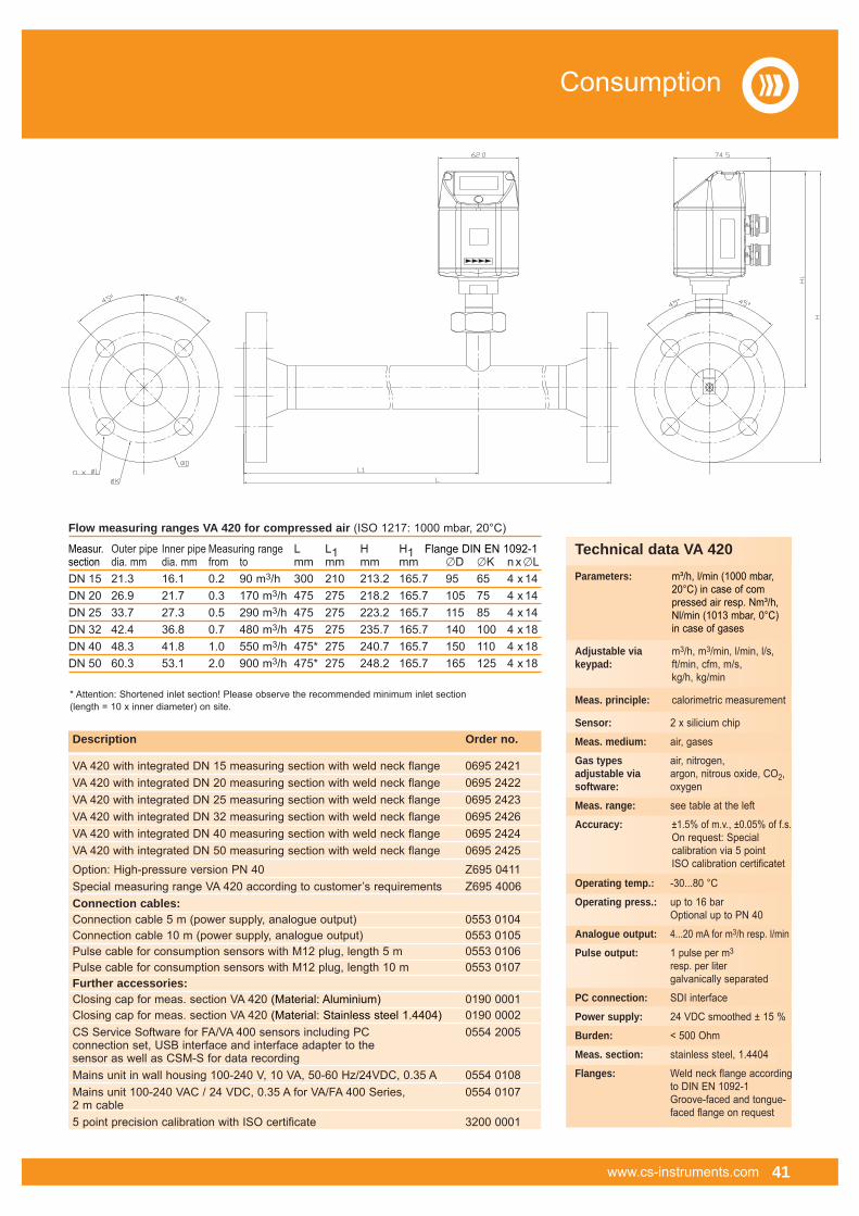
www.cs-instruments.com 41
Consumption
Flow measuring ranges VA 420 for compressed air (ISO 1217: 1000 mbar, 20°C)
Measur. Outer pipe Inner pipe Measuring range L L1 H H1 Flange DIN EN 1092-1section dia. mm dia. mm from to mm mm mm mm �D �K n x �LDN 15 21.3 16.1 0.2 90 m3/h 300 210 213.2 165.7 95 65 4 x 14 DN 20 26.9 21.7 0.3 170 m3/h 475 275 218.2 165.7 105 75 4 x 14DN 25 33.7 27.3 0.5 290 m3/h 475 275 223.2 165.7 115 85 4 x 14DN 32 42.4 36.8 0.7 480 m3/h 475 275 235.7 165.7 140 100 4 x 18 DN 40 48.3 41.8 1.0 550 m3/h 475* 275 240.7 165.7 150 110 4 x 18 DN 50 60.3 53.1 2.0 900 m3/h 475* 275 248.2 165.7 165 125 4 x 18
* Attention: Shortened inlet section! Please observe the recommended minimum inlet section (length = 10 x inner diameter) on site.
Description Order no.
VA 420 with integrated DN 15 measuring section with weld neck flange 0695 2421VA 420 with integrated DN 20 measuring section with weld neck flange 0695 2422VA 420 with integrated DN 25 measuring section with weld neck flange 0695 2423VA 420 with integrated DN 32 measuring section with weld neck flange 0695 2426VA 420 with integrated DN 40 measuring section with weld neck flange 0695 2424VA 420 with integrated DN 50 measuring section with weld neck flange 0695 2425Option: High-pressure version PN 40 Z695 0411Special measuring range VA 420 according to customer’s requirements Z695 4006Connection cables:Connection cable 5 m (power supply, analogue output) 0553 0104Connection cable 10 m (power supply, analogue output) 0553 0105Pulse cable for consumption sensors with M12 plug, length 5 m 0553 0106Pulse cable for consumption sensors with M12 plug, length 10 m 0553 0107Further accessories:Closing cap for meas. section VA 420 (Material: Aluminium) 0190 0001Closing cap for meas. section VA 420 (Material: Stainless steel 1.4404) 0190 0002 CS Service Software for FA/VA 400 sensors including PC 0554 2005connection set, USB interface and interface adapter to the sensor as well as CSM-S for data recordingMains unit in wall housing 100-240 V, 10 VA, 50-60 Hz/24VDC, 0.35 A 0554 0108Mains unit 100-240 VAC / 24 VDC, 0.35 A for VA/FA 400 Series, 0554 01072 m cable 5 point precision calibration with ISO certificate 3200 0001
Technical data VA 420Parameters: m³/h, l/min (1000 mbar, 20°C) in case of com pressed air resp. Nm³/h, Nl/min (1013 mbar, 0°C) in case of gases
Adjustable via m3/h, m3/min, l/min, l/s, keypad: ft/min, cfm, m/s, kg/h, kg/min
Meas. principle: calorimetric measurement
Sensor: 2 x silicium chip
Meas. medium: air, gases
Gas types air, nitrogen, adjustable via argon, nitrous oxide, CO2, software: oxygen
Meas. range: see table at the left
Accuracy: ±1.5% of m.v., ±0.05% of f.s. On request: Special calibration via 5 point ISO calibration certificatet
Operating temp.: -30...80 °C
Operating press.: up to 16 bar Optional up to PN 40
Analogue output: 4...20 mA for m3/h resp. l/min
Pulse output: 1 pulse per m3 resp. per liter galvanically separated
PC connection: SDI interface
Power supply: 24 VDC smoothed ± 15 %
Burden: < 500 Ohm
Meas. section: stainless steel, 1.4404
Flanges: Weld neck flange according to DIN EN 1092-1 Groove-faced and tongue- faced flange on request

42 www.cs-instruments.com
Consumption
What are the advantages of the consumption measuring technology of CS Instruments?
Inner diameter of pipe VA 400 Standard VA 400 Max. VA 400 HighSpeed (92.7 m/s) (185.0 m/s) (224.0 m/s)Inch mm Meas. ranges Meas. ranges Meas. ranges from ... to from ... to from ... to1/2” 16.1 DN 15 2.5...760 l/min 3.5...1516 l/min 6.0...1836 l/min3/4” 21.7 DN 20 0.3...89 m3/h 0.4...178 m3/h 0.7...215 m3/h1” 27.3 DN 25 0.5...148 m3/h 0.6...295 m3/h 1.1...357 m3/h1 1/4” 36.0 DN 32 0.9...280 m3/h 1.2...531 m3/h 2.5...644 m3/h1 1/2” 41.8 DN 40 1.2...365 m3/h 1.5...728 m3/h 3.0...882 m3/h2” 53.1 DN 50 2...600 m3/h 2.5...1198 m3/h 4.6...1450 m3/h2 1/2” 71.1 DN 65 3.5...1096 m3/h 5...2187 m3/h 7...2648 m3/h3” 84.9 DN 80 5...1570 m3/h 7...3133 m3/h 12...3794 m3/h4” 110.0 DN 100 9...2645 m3/h 12...5279 m3/h 16...6391 m3/h5” 133.7 DN 125 13...3912 m3/h 18...7808 m3/h 24...9453 m3/h6” 159.3 DN 150 18...5560 m3/h 25...11097 m3h 43...13436 m3/h8” 200.0 DN 200 26...8786 m3/h 33...17533 m3/h 50...21230 m3/h10” 250.0 DN 250 40...13744 m3h 52...27429 m3/h 80...33211 m3/h12” 300.0 DN 300 60...19815 m3/h 80...39544 m3/h 100...47881 m3/h
Drilling under pressureA Screw neck B Spot drilling collar
� Even under pressure, the consumption probe VA 400 is mounted by means of a standard 1/2" ball valve. During mounting and dismounting the safety ring avoids an uncontrolled ejection of the probe which may be caused by the operating pressure.
For the mounting into different pipe diameters VA 400 is available in the following probe lengths: 120, 160, 220, 300, 400 mm.
So the consumption probes are being mounted into existing pipelines with inner diameters of 1/2" upwards.
The exact positioning of the sensor in the middle of the pipe is granted by means of the engraved depth scale. The maximum mounting depth corresponds with the respective probe length. Example: VA 400 with probe length 220 mm has a maximummounting depth of 220 mm.
� If there is no suitable measuring site with a 1/2" ball valve present there are two simple possibilities to set up a measuring point:
A Weld on a 1/2” screw neck and screw on a 1/2” ball valve.
B Mount spot drilling collar incl. ball valve (see accessories).
By means of the drilling jig it is possible to drill under pressure through the 1/2" ball valve into the existing pipeline. The drilling chips are collected in a filter. Then the probe can be mounted as described under point A.
� Due to the large measuring range of the probe even extreme requirements to the consumption measurement (high volume flow in small pipe diameters) can be met. The measuring range is depending on the pipe diameter - see table on the right hand side.
1/2” ball valveclosed
1/2” mountingthread
engraveddepth scale
safety ring
mounting depth = x + y
dA = outer diameter
x =
y
�
�
�
� �
�
x
d A
dA2
Flow measuring ranges VA 400 for compressed air (ISO 1217: 1000 mbar, 20°C)

www.cs-instruments.com 43
Description Order no. VA 400 consumption sensor in basic version: 0695 4001Standard (92.7 m/s), probe length 220 mm, without displayOptions for VA 400:Display Z695 4000Max. version (185 m/s) Z695 4003HighSpeed version (224 m/s) Z695 4002Probe length 120 mm ZSL 0120Probe length 160 mm ZSL 0160Probe length 300 mm ZSL 0300Probe length 400 mm ZSL 0400Connection cables:Connection cable, 5 m (power supply, analogue output, pulse output) 0553 0104Connection cable, 10 m (power supply, analogue output, pulse output) 0553 0105Additional accessories:CS Service Software for FA/VA 400 sensors incl. PC connection set, 0554 2005USB adapter and interface adapter to sensor as well as CSM-S for data recordingMains unit in wall housing 100-240 V, 10 VA, 50-60 Hz/24 VDC, 0,35 A 0554 0108 External wall display multifunction measuring instrument DS 300 see page 365 point precision calibration with ISO certificate 3200 0001
VA 400Consumption sensorfor compressed air and gases
The new VA 400 for consumption measurement of com-pressed air and gases in a robust housing with and without display with actual consumption in m3/h and counter in m3.
Technical data VA 400Parameters: m³/h, l/min (1000 mbar, 20 °C) in case of com pressed air resp. Nm³/h, Nl/min (1013 mbar, 0 °C) in case of gases
Adjustable via m3/h, m3/min, l/min, l/s, software: ft/min, cfm, m/s, kg/h, kg/min. Adjustable via diameter for volume flow keypad: calculation, counter resettableMeas. principle: calorimetric measurement
Sensor: 2 x silicium chip
Meas. medium: air, gases
Gas types air, nitrogen, adjustable via argon, helium, CO2, software: oxygen
Meas. range: see table page 34
Accuracy: ± 4 % m.v. ± 3 % m.v. via 5 point ISO precision calibration
Operating temp.: -30...110 °C probe tube -30...80 °C housing
Operating pressure: up to 50 bar
Analogue output: 4...20 mA for m3/h resp. l/min; on request: scaling for cfm, m3/min, l/min, l/s, ft/min, m/s
Pulse output: 1 pulse per m3, signal high 24 VDC, for 30 ms
PC connection: SDI interface
Power supply: 24 VDC
Burden: < 500 Ohm
Housing: polycarbonate
Probe tube: stainless steel, 1,4301 mounting length 220 mm, Ø 10 mm
Mounting thread: G1/2”
Diameter housing: 65 mm
flexible mounting thread G1/2”
safety ringØ 11.7 mm
Special features
� Integrated display for m3/h und m3
� Depth scale for accurate installation� Usable from 1/2” to 12” (DN 300)� Easy installation under pressure� 4...20 mA analogue output for m3/h resp. m3/min� Pulse output for m3
� Inner diameter adjustable via keypad � Consumption counter resettable
engraveddepth scale
safety ring
mounting depth = x + y
dA = outer diameter
x =
y
�
�
�
� �
�
x
d A
Consumption
dA2
Inner diameteradjustable via keypad

44 www.cs-instruments.com
Flow station DS 300 with consumption counter
Consumption
DS 300 displays the actual value (m3/h, m3/min) and the total consumption.A 4...20 mA output for m3/h and a pulse output for m3 are available for routing to a superior building management system (PLC)
Special features
� Usable from 1/2” to 12” (DN 300)
� All-in-one solution, small installation expenditure
� 2 displays, actual flow and total consumption
� Easy installation and removal of the sensor under pressure
� Highest accuracy due to 5 point precision calibration
� Output 4 to 20 mA for m3h, pulse output for m3
� Easy handling: – Inner diameter freely adjustable – in DS 300 – 2 alarm values freely adjustable – Optical display in case of alarm – Consumption counter resettable
� Dew point sensor connectable
Flow measuring ranges VA 400 for compressed air (ISO 1217: 1000 mbar, 20°C)
The large measuring range of the consumption sensors enable the recordings of high consumptions (e. g. on weekdays) and the determination of leakages of a few litres/min (e. g. weekends).
Flow station DS 300 with consumption counter consisting of:� Multifunction measuring instrument DS 300� Consumption probe VA 400� Available with and without measuring section
Installation even under pressure via customary 1/2” ball valve
Inner diameter of pipe VA 400 Standard VA 400 Max. VA 400 HighSpeed (92.7 m/s) (185.0 m/s) (224.0 m/s)Inch mm Meas. ranges Meas. ranges Meas. ranges from ... to from ... to from ... to1/2” 16.1 DN 15 2.5...760 l/min 3.5...1516 l/min 6.0...1836 l/min3/4” 21.7 DN 20 0.3...89 m3/h 0.4...178 m3/h 0.7...215 m3/h1” 27.3 DN 25 0.5...148 m3/h 0.6...295 m3/h 1.1...357 m3/h1 1/4” 36.0 DN 32 0.9...280 m3/h 1.2...531 m3/h 2.5...644 m3/h1 1/2” 41.8 DN 40 1.2...365 m3/h 1.5...728 m3/h 3.0...882 m3/h2” 53.1 DN 50 2...600 m3/h 2.5...1198 m3/h 4.6...1450 m3/h2 1/2” 71.1 DN 65 3.5...1096 m3/h 5...2187 m3/h 7...2648 m3/h3” 84.9 DN 80 5...1570 m3/h 7...3133 m3/h 12...3794 m3/h4” 110.0 DN 100 9...2645 m3/h 12...5279 m3/h 16...6391 m3/h5” 133.7 DN 125 13...3912 m3/h 18...7808 m3/h 24...9453 m3/h6” 159.3 DN 150 18...5560 m3/h 25...11097 m3/h 43...13436 m3/h8” 200.0 DN 200 26...8786 m3/h 33...17533 m3/h 50...21230 m3/h10” 250.0 DN 250 40...13744 m3/h 52...27429 m3/h 80...33211 m3/h12” 300.0 DN 300 60...19815 m3/h 80...39544 m3/h 100...47881 m3/h
engraveddepth scale
safety ring
mounting depth = x + y
dA = outer diameter
x =
y
�
�
�
� �
�
x
d A
dA2
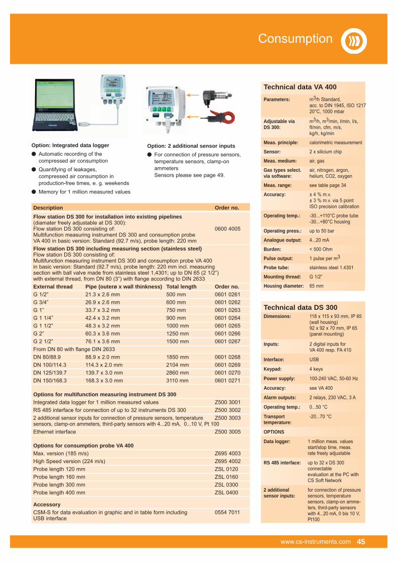
www.cs-instruments.com 45
Consumption
Option: Integrated data logger� Automatic recording of the compressed air consumption� Quantifying of leakages, compressed air consumption in production-free times, e. g. weekends� Memory for 1 million measured values
Option: 2 additional sensor inputs� For connection of pressure sensors, temperature sensors, clamp-on ammeters Sensors please see page 49.
Technical data VA 400Parameters: m3/h Standard, acc. to DIN 1945, ISO 1217 20°C, 1000 mbar
Adjustable via m3/h, m3/min, l/min, l/s,DS 300: ft/min, cfm, m/s, kg/h, kg/min
Meas. principle: calorimetric measurement
Sensor: 2 x silicium chip
Meas. medium: air, gas
Gas types select. air, nitrogen, argon,via software: helium, CO2, oxygen
Meas. range: see table page 34
Accuracy: ± 4 % m.v. ± 3 % m.v. via 5 point ISO precision calibration
Operating temp.: -30...+110°C probe tube -30...+80°C housing
Operating press.: up to 50 bar
Analogue output: 4...20 mA
Burden: < 500 Ohm
Pulse output: 1 pulse per m3
Probe tube: stainless steel 1.4301
Mounting thread: G 1/2”
Housing diameter: 65 mm
Technical data DS 300Dimensions: 118 x 115 x 93 mm, IP 65 (wall housing) 92 x 92 x 70 mm, IP 65 (panel mounting)
Inputs: 2 digital inputs for VA 400 resp. FA 410
Interface: USB
Keypad: 4 keys
Power supply: 100-240 VAC, 50-60 Hz
Accuracy: see VA 400
Alarm outputs: 2 relays, 230 VAC, 3 A
Operating temp.: 0...50 °C
Transport -20...70 °Ctemperature:
OPTIONS
Data logger: 1 million meas. values start/stop time, meas. rate freely adjustable
RS 485 interface: up to 32 x DS 300 connectable evaluation at the PC with CS Soft Network
2 additional for connection of pressuresensor inputs: sensors, temperature sensors, clamp-on amme- ters, third-party sensors with 4...20 mA, 0 bis 10 V, Pt100
Description Order no. Flow station DS 300 for installation into existing pipelines (diamater freely adjustable at DS 300): Flow station DS 300 consisting of: 0600 4005 Multifunction measuring instrument DS 300 and consumption probeVA 400 in basic version: Standard (92.7 m/s), probe length: 220 mmFlow station DS 300 including measuring section (stainless steel)Flow station DS 300 consisting of: Multifunction measuring instrument DS 300 and consumption probe VA 400 in basic version: Standard (92.7 m/s), probe length: 220 mm incl. measuring section with ball valve made from stainless steel 1,4301; up to DN 65 (2 1/2”) with external thread, from DN 80 (3”) with flange according to DIN 2633External thread Pipe (outerø x wall thinkness) Total length Order no.G 1/2” 21.3 x 2.6 mm 500 mm 0601 0261G 3/4” 26.9 x 2.6 mm 600 mm 0601 0262G 1” 33.7 x 3.2 mm 750 mm 0601 0263G 1 1/4” 42.4 x 3.2 mm 900 mm 0601 0264G 1 1/2” 48.3 x 3.2 mm 1000 mm 0601 0265G 2” 60.3 x 3.6 mm 1250 mm 0601 0266G 2 1/2” 76.1 x 3.6 mm 1500 mm 0601 0267From DN 80 with flange DIN 2633 DN 80/88.9 88.9 x 2.0 mm 1850 mm 0601 0268DN 100/114.3 114.3 x 2.0 mm 2104 mm 0601 0269DN 125/139.7 139.7 x 3.0 mm 2860 mm 0601 0270DN 150/168.3 168.3 x 3.0 mm 3110 mm 0601 0271
Options for multifunction measuring instrument DS 300Integrated data logger for 1 million measured values Z500 3001RS 485 interface for connection of up to 32 instruments DS 300 Z500 30022 additional sensor inputs for connection of pressure sensors, temperature Z500 3003sensors, clamp-on ammeters, third-party sensors with 4...20 mA, 0...10 V, Pt 100Ethernet interface Z500 3005
Options for consumption probe VA 400Max. version (185 m/s) Z695 4003High Speed version (224 m/s) Z695 4002Probe length 120 mm ZSL 0120Probe length 160 mm ZSL 0160Probe length 300 mm ZSL 0300Probe length 400 mm ZSL 0400
AccessoryCSM-S for data evaluation in graphic and in table form including 0554 7011 USB interface

46 www.cs-instruments.com
Consumption
Description Order no.
Flow direction switch VA 409 0695 0409Mains unit in wall housing 0554 0108Connection cable VA/FA Series 400, 5 m with M12 plug 0553 0104Connection cable VA/FA Series 400, 10 m with M12 plug 0553 0105
VA 409Flow direction switch for compressed air systems
The new thermal flow direction switch VA 409 with direction indication serves for determination of the flow direction of compressed air and gases especially in closed circular pipelines.
By means of VA 409 with flow direction indication the flow direction of the compressed air can be determined quickly and safely. Compared with the former mechanical paddle flow switches VA 409 is able to detect even the smallest changes in the flow direction quickly and without any mechanical movement.
The direction information in form of a potential-free contact (normally closed max. 60 VDC, 0.5 A) is transferred to the consumption sensors VA 400/VA 420 or to a separate building management system (mbs). Two LEDs show the flow direction.
In connection with 2 consumption sensors VA 400/VA 420 incoming and outflowing compressed air in closed circular pipelines can be measured precisely.
Special features� detects smallest changes < 0.1 m/s referred to 20 °C and 1000 mbar
� no mechanical wear parts
� easy installation under pressure
Technical data VA 409Detection range < 0.1 m/s referred torecognition flow 20°C and 1000 mbardirection:Measuring principle: calorimetric measurementSensor: Pt 30/Pt 700/Pt 330Measuring medium: air, gasesOperating temp.: 0...50 °C probe tube -20...70 °C housingOperating pressure: up to 16 barPower supply: 24 VDC, 40 mAPower input: max. 80 mA up to 24 VDCProtection class: IP 54EMV: acc. to DIN EN 61326Connection: 2 x M12, 5-pole, plug A and plug B2 potential-free 2 x U max. 60 VDC,contacts: l max 0,5 A (normally closed); on request: Normally openHousing: polycarbonateProbe tube: stainless steel, 1,4301, length 160 mm, Ø 10 mm, safety ring Ø 11.5 mm, longer probes on request Mounting thread: G 1/2”Diameter housing: 65 mmFlow direction: 2 LEDs

www.cs-instruments.com 47
Consumption
Flow station DS 300with direction indication in one direction
By connecting the flow direction switch VA 409 to the flow station DS 300 only the consumption in one direction is measured. So it is guaranteed that the back-flowing compressed air is not counted twice.
Special features� precise consumption measurement in one direction
� when doing the cost calculation of the compressed air it is avoided that back- flowing compressed air is counted twice
Flow station DS 300with flow direction indication in both directions
For this reason two flow stations DS 300 are used for precise consumption measurement of both flow directions.
Special features� precise consumption measurement in both directions
� separate indication of the actual consumption (m³/h resp. m³/min etc…) separate summing of the total consumption (m³ resp. l)
� forwarding of the analogue output and of the pulse output for the respective flow direction
In case the flow direction switch VA 409 indicates the flow direction and forwards this information to the flow station DS 300.
Each of both flow stations DS 300 exclusively measures the flow in one direction. The flow direction switch VA 409 is mounted in the middle between both flow stations in order to avoid flow turbulences.
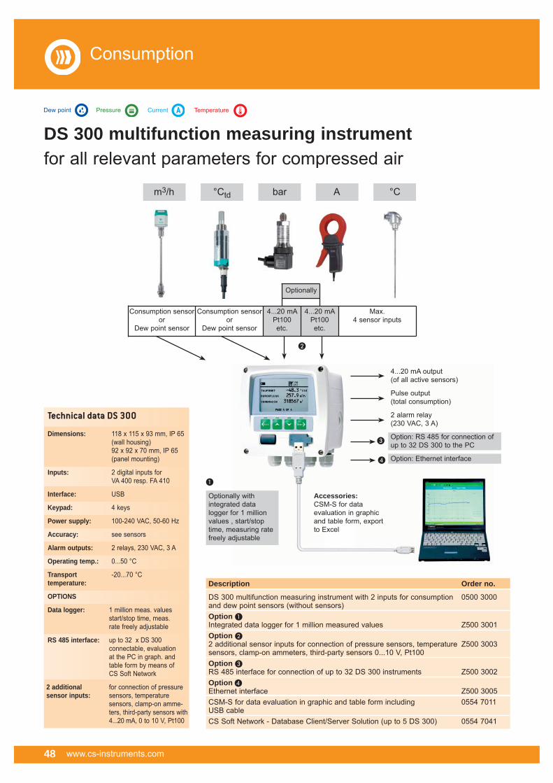
48 www.cs-instruments.com
DS 300 multifunction measuring instrument for all relevant parameters for compressed air
Optionally with integrated data logger for 1 million values , start/stop time, measuring rate freely adjustable
4...20 mA output(of all active sensors)
Pulse output(total consumption)
2 alarm relay(230 VAC, 3 A)
Option: RS 485 for connection ofup to 32 DS 300 to the PC
Option: Ethernet interface
Accessories:CSM-S for data evaluation in graphic and table form, export to Excel
�
�
�
Consumption
Consumption sensoror
Dew point sensor
Consumption sensoror
Dew point sensor
Max. 4 sensor inputs
4...20 mAPt100etc.
4...20 mAPt100etc.
�
m3/h °Ctd bar A °C
Optionally
TemperatureDew point Pressure Current
Technical data DS 300
Dimensions: 118 x 115 x 93 mm, IP 65 (wall housing) 92 x 92 x 70 mm, IP 65 (panel mounting)
Inputs: 2 digital inputs for VA 400 resp. FA 410
Interface: USB
Keypad: 4 keys
Power supply: 100-240 VAC, 50-60 Hz
Accuracy: see sensors
Alarm outputs: 2 relays, 230 VAC, 3 A
Operating temp.: 0...50 °C
Transport -20...70 °Ctemperature:
OPTIONS
Data logger: 1 million meas. values start/stop time, meas. rate freely adjustable
RS 485 interface: up to 32 x DS 300 connectable, evaluation at the PC in graph. and table form by means of CS Soft Network
2 additional for connection of pressuresensor inputs: sensors, temperature sensors, clamp-on amme- ters, third-party sensors with 4...20 mA, 0 to 10 V, Pt100
Description Order no.
DS 300 multifunction measuring instrument with 2 inputs for consumption 0500 3000and dew point sensors (without sensors)Option �Integrated data logger for 1 million measured values Z500 3001Option �2 additional sensor inputs for connection of pressure sensors, temperature Z500 3003sensors, clamp-on ammeters, third-party sensors 0...10 V, Pt100Option �RS 485 interface for connection of up to 32 DS 300 instruments Z500 3002Option �Ethernet interface Z500 3005CSM-S for data evaluation in graphic and table form including 0554 7011 USB cableCS Soft Network - Database Client/Server Solution (up to 5 DS 300) 0554 7041

www.cs-instruments.com 49
DS 300 multifunction measuring instrument Suitable probes at a glanceDescription Order no. Consumption probes:VA 400 consumption probe in basic version: 0695 4001Standard (92.7 m/s), probe length 220 mm, without displayOptions for VA 400:Max. version (185 m/s) Z695 4003HighSpeed version (224 m/s) Z695 4002Probe length 120 mm ZSL 0120Probe length 160 mm ZSL 0160Probe length 300 mm ZSL 0300Probe length 400 mm ZSL 0400Dew point sensors:FA 410 dew point sensor, -80°...20°Ctd including inspection certificate 0699 0410FA 410 dew point sensor, -20°...50°Ctd including inspection certificate 0699 0412Connection cables for VA 400, FA 410:Connection cable, length: 5 m, to DS 300 0553 0104Connection cable, length: 10 m, to DS 300 0553 0105Connection cable, length: 5 m, with ODU plug to DS 300 mobile version 0553 0111Pressure sensors:Precision pressure sensor CS 16, 0...16 bar, ± 0.5 % accuracy of full scale 0694 3555 Precision pressure sensor CS 40, 0...40 bar, ± 0.5 % accuracy of full scale 0694 3930 Precision pressure sensor CS 1.6 absolute, 0...1.6 bar abs., 0694 3550 ± 0.5 % accuracy of full scalePrecision pressure sensor CS -1...15 bar, ± 0.5 % accuracy of full scale 0694 3553 Standard pressure sensor CS 16, 0...16 bar, ± 1 % accuracy of full scale 0694 1886 Standard pressure sensor CS 40, 0...40 bar, ± 1 % accuracy of full scale 0694 0356 Standard pressure sensor CS 1.6 absolute, 0...1.6 bar abs., 0694 3551 ± 1 % accuracy of full scaleStandard pressure sensor up to 100 bar / 250 bar / 400 bar on request Connection cables for pressure sensors:Connection cable, length: 5 m, to DS 300 0553 0108Connection cable, length : 10 m, to DS 300 0553 0109Connection cable, length: 5 m, with ODU plug to DS 300 mobile version 0553 0110Temperature probes:Screw-in temperature probe Pt 100, Class A, length 300 mm, Ø 6 mm, 0693 0002with measuring transducer 4...20 mA = -50...+500°C (2-wire technology)Indoor/outdoor temperature probe Pt 100, Class A, -50...+100°C 0604 0101Indoor/outdoor temperature probe Pt 100, Class A with measuring 0693 0001transducer 4...20 mA = -50...+100°C (2-wire technology)Connection cables for temperature probes:Connection cable, length: 5 m, to DS 300 0553 0108Connection cable, length: 10 m, to DS 300 0553 0109Connection cable, length: 5 m, with ODU plug to DS 300 mobile version 0553 0110Temperature probe cable Pt 100, Class A, length 300 mm, Ø 6 mm, 0604 0102-50...+180°C, 5 m probe connection cable with open endsTemperature probe cable Pt 100, Class A, length 150 mm, Ø 6 mm, 0604 0100-50...+180°C, 5 m probe connection cable with open endsClamp screwing 6 mm, G 1/2”, PTFE clamping ring, pressure-tight up to 6 bar 0554 6003Clamp screwing 6 mm, G 1/2”, VA clamping ring, pressure-tight up to 10 bar 0554 6004Clamp-on ammeters:Clamp-on ammeter 0...1000 A TRMS incl. 5 m connection cable with open ends 0554 0507
Consumption
TemperatureDew point Pressure Current
• Pressure sensor
• Screw-in• temperature probe
• Indoor/outdoor• temperature probe
• Clamp screwing
• Temperature probe cable
• Clamp-on ammeter
• VA 400
• FA 410

50 www.cs-instruments.com
Consumption
DS 300 – Connection to BUS systems
Description Order no. Options for multifunction measuring instrument DS 300 Integrated data logger for 1 million measured values Z500 3001RS 485 interface for connection of up to 32 DS 300 instruments Z500 3002Ethernet interface Z500 3005
AccessoriesCS Soft Network - Database Client/Server Solution (up to 5 DS 300) 0554 7041
The following BUS systems can be realised:
� M-Bus
� Profibus DP Slave
� Modbus/RTU (RS 485)
� Modbus/RTU - Modbus/TCP (Ethernet)
� Modbus/RTU over TCP (Ethernet)
� Modbus/TCP (Ethernet)
The right housing foreach application
• For panel mounting• Mounting dimensions: 92 x 92 x 70 mm
• Ethernet interface
• For wall mounting
• Easy wall mounting
R S 4 8 5
E T H E R N E T
RS 485
Ethernet-Gateway

www.cs-instruments.com 51
DS 300 – sophisticated operational concept
Main menu
Logger operationSet Alarm 1Set Alarm 2System status and settingSensor setting
Menu logger operationSet logging rateKey start Time startLogger memoryView protocolFormat logger
Sensor setting consumption
Adjust inner diameterTotal consumption counterVolume flow unitConsumption unit
DS 300 convinces due to its sophisticated operational concept which is similar to the self-explanatory operation of modern mobile phones.
By using the <Enter> key the user enters the menus,
by using the <Back> key each step can be cancelled. Selection is done by the <arrow up> and <arrow down> key.
All important parameters can be set on-site via the keypad.
Enter threshold value alarm relay 1 (not in case of DS 300 mobile version)Enter threshold value alarm relay 2 (not in case of DS 300 mobile version)Set date / time
The measuring rate can be freely adjusted between 1 second up to 59 minutes 59 secondsLogger starts at the push of a button / stops at the push of a buttonLogger starts at a defined date / timeShows the available recording time in hours, minutesRetrieving of stored protocols with Min, Max, average valuesDeletion of the whole memory content
Inner diameter freely adjustable. Important for calculation in m3/hReset of total consumption counter to zeroVolume flow unit freely selectable: m3/h, m3/min, l/min, l/s, cfmConsumption unit: m3, l, c
Consumption

52 www.cs-instruments.com
Description Order no. Drilling jig incl. drill (Ø 13 mm) 0530 1108High-pressure protection recommended for installation from 10 to 50 bar 0530 1105
Useful accessories:Measuring sections
• Drilling under pressure
External thead Pipe (outerø x wall thickness) Total length Order no.G 1/4” 20.0 x 7.0 mm 180 mm 4000 0006G 1/2” 21.3 x 2.6 mm 500 mm 4000 0015G 3/4” 26.9 x 2.6 mm 600 mm 4000 0020G 1” 33.7 x 3.2 mm 750 mm 4000 0025G 1 1/4” 42.4 x 3.2 mm 900 mm 4000 0032G 1 1/2” 48.3 x 3.2 mm 1000 mm 4000 0040G 2” 60.3 x 3.6 mm 1250 mm 4000 0050G 2 1/2” 76.1 x 3.6 mm 1500 mm 4000 0065from DN 80 with flange DIN 2633 DN 80/88.9 88.9 x 2.0 mm 1850 mm 4000 0080DN 100/114.3 114.3 x 2.0 mm 2104 mm 4000 0100DN 125/139.7 139.7 x 3.0 mm 2860 mm 4000 0125DN 150/168,3 168,3 x 3,0 mm 3110 mm 4000 0150
Measuring sections for precise measurementsMeas. section made of stainless steel 1.4301 incl. ball valve, up to DN 65 (G2 1/2”)with external thread, from DN 80 with weld neck flange according to DIN 2633.
Drilling jig for drilling under pressure
By means of a special drilling device a measuring site with 1/2" ball valve can be easily set up within a few minutes. As an alternative to the welding of the 1/2” fitting also a spot drilling collar (see page 45) can be used.
• Measuring section 1/2”
• Measuring section 1/4”
• Drilling jig • High-pressure • protection
Consumption

www.cs-instruments.com 53
• Spot drilling collar
Description Order no.
Thickness meter CS 0495 including case and calibration block 0560 0495
Useful accessories:Spot drilling collars
Technical data CS 0495Meas. range: 1.5…200 mm, 0.06…8 Inch
Meas. prinicple: ultrasonicMeasured steel, cast iron, materials: aluminium, copper, brass, zinc, quartz glass, polyethylene, PVC, grey iron, nodular cast ironCalibration block: included in shipmentResolution: 0.1 mmAccuracy: ± (0.5 % n+0.1)Power supply: 4 x 1.5 V AA (UM-3) batteriesDimensions: 160 x 68 x 32 mmWeight: 208 g
If there is no measuring site with 1/2" ball valve present it can be set up by means of spot drilling collars.The spot drilling collar is imposed onto the pipe and tightened via thread rods. The enveloping rubber gasket is pressure-tight up to 10 bar. By means of the drilling jig (page 44) it is possible to drill through the 1/2" ball valve into the existing pipe. Important: Please indicate the exact outer diameter of the existing pipe when placing the order resp. please select the suitable spot drilling collar from the adjoining list.
Thickness meter CS 0495
The entry of the correct inner diameter is essential for an accurate consumption measurement. The thickness meter CS 0495 enablesa quick, easy and accurate measurement of the wall thickness of pipes. So the determination of the inner diameter becomes very easy.
Consumption
Description DN Order no. Spot drilling collar for pipe Ø 032 - 036 mm, Length: 100 mm,* 0500 0446Spot drilling collar for pipe Ø 036 - 040 mm, Length: 100 mm,* 0500 0448Spot drilling collar for pipe Ø 040 - 044 mm, Length: 150 mm,* 0500 0449Spot drilling collar for pipe Ø 044 - 051 mm, Length: 200 mm,* 0500 0610Spot drilling collar for pipe Ø 048 - 055 mm, Length: 200 mm,* 40 0500 0611Spot drilling collar for pipe Ø 052 - 059 mm, Length: 200 mm,* 0500 0612Spot drilling collar for pipe Ø 057 - 064 mm, Length: 200 mm,* 50 0500 0613Spot drilling collar for pipe Ø 063 - 070 mm, Length: 200 mm,* 0500 0614Spot drilling collar for pipe Ø 070 - 077 mm, Length: 200 mm,* 65 0500 0615Spot drilling collar for pipe Ø 075 - 083 mm, Length: 200 mm,* 0500 0616Spot drilling collar for pipe Ø 082 - 090 mm, Length: 200 mm,* 0500 0617Spot drilling collar for pipe Ø 087 - 097 mm, Length: 200 mm,* 80 0500 0618Spot drilling collar for pipe Ø 095 - 104 mm, Length: 200 mm,* 0500 0619Spot drilling collar for pipe Ø 102 - 112 mm, Length: 200 mm,* 0500 0620Spot drilling collar for pipe Ø 108 - 118 mm, Length: 200 mm,* 100 0500 0621Spot drilling collar for pipe Ø 118 - 128 mm, Length: 200 mm,* 0500 0622Spot drilling collar for pipe Ø 125 - 135 mm, Length: 200 mm,* 0500 0623Spot drilling collar for pipe Ø 133 - 144 mm, Length: 200 mm,* 125 0500 0624Spot drilling collar for pipe Ø 145 - 155 mm, Length: 250 mm,* 0500 0625Spot drilling collar for pipe Ø 151 - 161 mm, Length: 250 mm,* 150 0500 0626Spot drilling collar for pipe Ø 159 - 170 mm, Length: 250 mm,* 0500 0627Spot drilling collar for pipe Ø 168 - 180 mm, Length: 250 mm,* 0500 0628Spot drilling collar for pipe Ø 180 - 191 mm, Length: 250 mm,* 175 0500 0629Spot drilling collar for pipe Ø 193 - 203 mm, Length: 300 mm,* 0500 0630Spot drilling collar for pipe Ø 200 - 210 mm, Length: 300 mm,* 0500 0631Spot drilling collar for pipe Ø 209 - 220 mm, Length: 300 mm,* 200 0500 0632
* incl. 1/2” ball valve

54 www.cs-instruments.com
Consumption
Description Order no.
Recalibration and 5 point precision calibration of flow sensor 0695 3333with ISO certificateVolume flow, freely selectable measuring points on request
Real gas calibration 3200 0015
Calibration range: from 0 to 4,000 m3/h under pressure
Accuracy of between 0.5 and the reference: 1 % of the meas. value
Calibration of consumption sensors and flow stationsIn the CS calibration laboratory for consumption sensors it is possible to calibrate consumption measuring instruments of CS Instruments as well as of other manufacturers. High precision reference measuring instruments grant an accuracy of up 0.5 % of the measured value.
Special feature
� Due to digital data transfer only the consumption sensor has to be calibrated, enabling the display unit DS 300 to stay on-site at all times.

Compressed air analysis seminar: m3/h, °Ctd, °C, A, bar. . .
Practical measurements and evaluationof the measuring results
Hands-on seminar on compressed air analysis:
� Compressed air quality according to ISO 8573
� Practical applications: Which compressed air quality is needed?
� Methods of compressed air drying and compressed air processing
� Moisture measurement in compressed air
� Costs of compressed air consumption
� Consumption measurement
Target groups / participants� Quality assurances employees
� Application planners
� Measurement and control technicians
� Maintenance employees
Basics in theory for humidity and consumption measurement
Seminars
www.cs-instruments.com 55

The telescope bar helps
locating leakages in pipelines up to a height of 6 m
Focus tube with focus tip avoids influence by ambient noise and enables preciselocating of leakages
Holding device of LD 300 at the telescope bar
Annual energy costs caused by leakages
Hole Loss in air Energy loss Costs p.a. Ø at 6 bar at 12 bar at 6 bar at 12 bar at 6 bar at 12 bar(mm) (l/s) (l/s) kW/h kW/h € €
1 1.2 1.8 0.3 1.0 144 480
3 11.1 20.8 3.1 12.7 1.488 6.096
5 30.9 58.5 8.3 33.7 3.984 16.176
10 123.8 235.2 33.0 132.0 15.840 63.360
Source: www.druckluft.effizient.de (*) kW x 0.06 € x 8.000 Bh/a
LD 300 leak detectorIf gases escape through leaks ultrasonic noises are generated. By means of the LD 300 leakages can be detected in the ultrasonic range even from distances of several meters. LD 300 transforms the inaudible signals into a frequency which can be identified by means of the provided sound-proof headset. In depressurized systems an ultrasonic tone generator can be used of which the signal travels through smallest openings.
Leak detection in:
� Compressed air lines, gas, vapour and vacuum plants
� Refrigerating plants
� Door seals
Applications:
Sound-proof headset enablesleak detection in extremely noisy environments
56 www.cs-instruments.com
Leakage
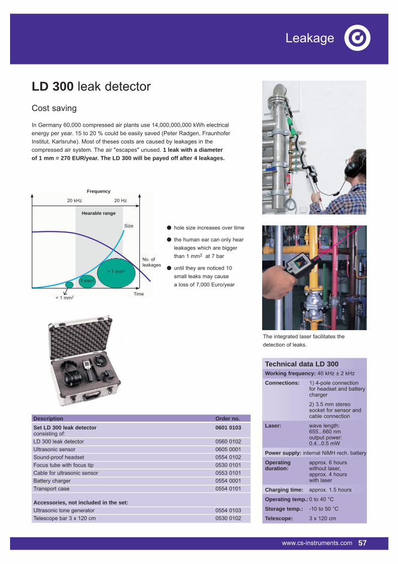
www.cs-instruments.com 57
Leakage
LD 300 leak detectorCost saving
In Germany 60,000 compressed air plants use 14,000,000,000 kWh electrical energy per year. 15 to 20 % could be easily saved (Peter Radgen, Fraunhofer Institut, Karlsruhe). Most of theses costs are caused by leakages in the compressed air system. The air "escapes" unused. 1 leak with a diameter of 1 mm = 270 EUR/year. The LD 300 will be payed off after 4 leakages.
Technical data LD 300Working frequency: 40 kHz ± 2 kHz
Connections: 1) 4-pole connection for headset and battery charger
2) 3.5 mm stereo socket for sensor and cable connection
Laser: wave length: 655...660 nm output power: 0.4...0.5 mW
Power supply: internal NiMH rech. battery
Operating approx. 6 hours duration: without laser, approx. 4 hours with laser
Charging time: approx. 1.5 hours
Operating temp.: 0 to 40 °C
Storage temp.: -10 to 50 °C
Telescope: 3 x 120 cm
Description Order no. Set LD 300 leak detector 0601 0103consisting of:LD 300 leak detector 0560 0102Ultrasonic sensor 0605 0001Sound-proof headset 0554 0102Focus tube with focus tip 0530 0101Cable for ultrasonic sensor 0553 0101Battery charger 0554 0001Transport case 0554 0101
Accessories, not included in the set:Ultrasonic tone generator 0554 0103Telescope bar 3 x 120 cm 0530 0102
� hole size increases over time
� the human ear can only hear leakages which are bigger than 1 mm2 at 7 bar
� until they are noticed 10 small leaks may cause a loss of 7,000 Euro/year
20 kHz
Hearable range
Frequency
20 Hz
Size
> 1 mm2
1 mm2
< 1 mm2Time
No. ofleakages
The integrated laser facilitates thedetection of leaks.
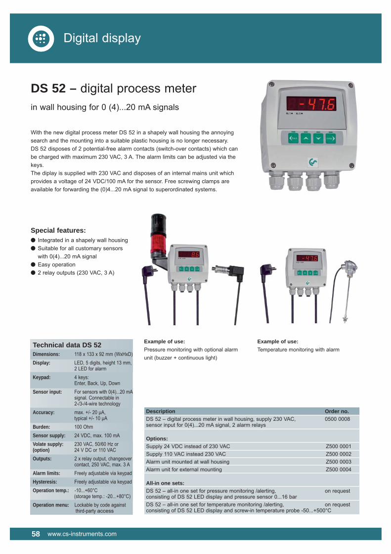
58 www.cs-instruments.com
Digital display
Description Order no.DS 52 – digital process meter in wall housing, supply 230 VAC, 0500 0008sensor input for 0(4)...20 mA signal, 2 alarm relays
Options:Supply 24 VDC instead of 230 VAC Z500 0001Supply 110 VAC instead 230 VAC Z500 0002Alarm unit mounted at wall housing Z500 0003Alarm unit for external mounting Z500 0004
All-in one sets:DS 52 – all-in one set for pressure monitoring /alerting, on requestconsisting of DS 52 LED display and pressure sensor 0...16 barDS 52 – all-in one set for temperature monitoring /alerting, on requestconsisting of DS 52 LED display and screw-in temperature probe -50...+500°C
Special features:� Integrated in a shapely wall housing� Suitable for all customary sensors with 0(4)...20 mA signal� Easy operation� 2 relay outputs (230 VAC, 3 A)
Example of use:Pressure monitoring with optional alarm unit (buzzer + continuous light)
Example of use:Temperature monitoring with alarm
DS 52 – digital process meterin wall housing for 0 (4)...20 mA signals
With the new digital process meter DS 52 in a shapely wall housing the annoying search and the mounting into a suitable plastic housing is no longer necessary. DS 52 disposes of 2 potential-free alarm contacts (switch-over contacts) which can be charged with maximum 230 VAC, 3 A. The alarm limits can be adjusted via the keys. The diplay is supplied with 230 VAC and disposes of an internal mains unit which provides a voltage of 24 VDC/100 mA for the sensor. Free screwing clamps are available for forwarding the (0)4...20 mA signal to superordinated systems.
Technical data DS 52Dimensions: 118 x 133 x 92 mm (WxHxD)Display: LED, 5 digits, height 13 mm, 2 LED for alarmKeypad: 4 keys: Enter, Back, Up, DownSensor input: For sensors with 0(4)...20 mA signal. Connectable in 2-/3-/4-wire technologyAccuracy: max. +/- 20 μA, typical +/- 10 μABurden: 100 OhmSensor supply: 24 VDC, max. 100 mAVolate supply: 230 VAC, 50/60 Hz or(option) 24 V DC or 110 VACOutputs: 2 x relay output, changeover contact, 250 VAC, max. 3 AAlarm limits: Freely adjustable via keypadHysteresis: Freely adjustable via keypadOperation temp.: -10...+60°C (storage temp.: -20...+80°C)Operation menu: Lockable by code against third-party access

www.cs-instruments.com 59
Digital displays
Description Order no.DS 51 – digital meter for panel mounting, supply 230 VAC, 0500 0006sensor input for 0(4)...20 mA signal, 2 alarm relays
Options:Supply 24 VDC instead of 230 VAC Z500 0001Supply 110 VAC instead of 230 VAC Z500 0002
DS 51 – digital panel meterfor 0 (4)...20 mA signals
The DS 51 digital panel meter disposes of 2 potential-free alarm contacts (change- over adjusted via the keys. The digital panel meter is supplied with 230 VAC and disposes of an internal mains unit which provides the voltage supply of 24 VDC/100 mA for the sensor.
Technical data DS 51Dimensions: 96 x 48 mm (WxH) Mounting depth: 95 mm
Display: LED, 5 digits, height 13 mm, 2 LED for alarm
Keypad: 3 keys: Set, Up, Down
Sensor input: For sensors with 0(4)...20 mA signal. Connectable in 2-/3-/4-wire technology
Accuracy: max. +/- 20 μA, typical +/- 10 μA
Burden: 100 Ohm
Sensor supply: 24 VDC, max. 100 mA
Voltage supply: 230 VAC, 50/60 Hz or(option) 24 V DC or 110 VAC
Outputs: 2 x relay output, changeover contact, 250 VAC, max. 3 A
Alarm values: Freely adjustable via keypad
Hysteresis Freely adjustable via keypad
Operation temp.: -10...+60°C (storage temp.: -20...+80°C)
Operation menu: Lockable by code against third-party access
Special features:� Suitable for all customary sensors with 0(4)...20 mA signal� Easy operation� 2 relay outputs (230 VAC, 3 A)

SALES OFFICE SOUTHCS INSTRUMENTS GmbHZindelsteiner Straße 15D-78052 VS-TannheimPhone +49 (0) 7705 978 99-0Fax +49 (0) 7705 978 [email protected]
SALES OFFICE NORTHCS INSTRUMENTS GmbHAm Oxer 28cD-24955 HarrisleePhone +49 (0) 461 700 20 25Fax +49 (0) 461 700 20 [email protected]
Prin
ted
in G
erm
any
- E -
10.2
012
Sub
ject
to c
hang
e w
ithou
t not
ice
Com
posi
tion/
desi
gn: K
ING
cre
ativ
+sat
z