full-scale atlas motion platform: structure; actuation...
TRANSCRIPT

Full-scale Atlas Motion Platform: Structure;Actuation; Control
Z. Copeland, B. Jung, M.J.D. Hayes, and R.G. Langlois
Department of Mechanical and Aerospace Engineering, Carleton University,Ottawa, Canadae-mail: [email protected]; [email protected];[email protected]; [email protected]
Abstract. This paper presents an overview of the design of the first full-scale prototype of theAtlas flight simulator motion platform for pilot training. The Atlas concept was introduced in2005, and is unique such that orientation is decoupled from positioning, and unlimited rotationsare possible about any axis of the mechanism. Detail design and manufacturing are complete,and assembly is in progress. Central to the design is three Mecanum wheels in an equilateralarrangement, which impart angular displacements to a sphere that houses the cockpit, therebyproviding rotational actuation. Since the Atlas sphere rests on these Mecanum wheels, there areno joints or levers constraining its motion, allowing full 360 rotation about all axes, yielding anunbounded orientation workspace that is singularity free. In this paper, the current state of thedesign and assembly regarding actuation, the spherical S-glass shell, and modelling for motioncontrol are discussed.
Key words: Unbounded orientation workspace; structural design; actuation; simulated dynamicresponse.
1 Introduction
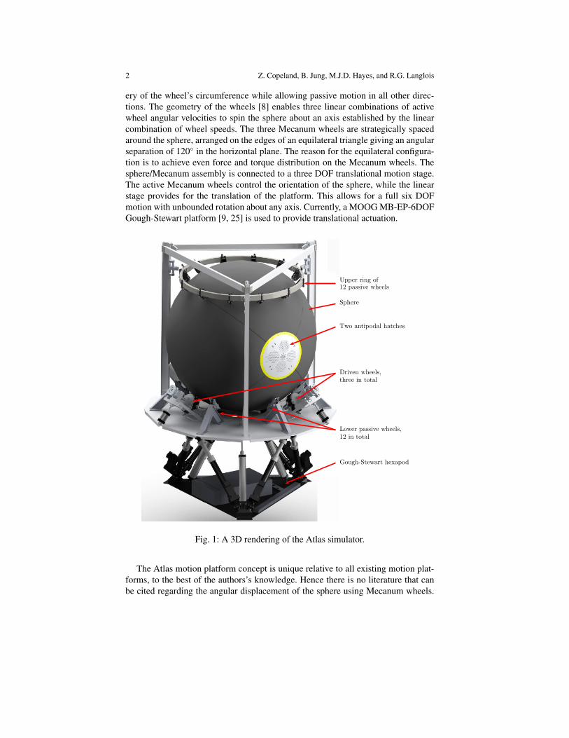
Conceptually introduced in 2005 [10], the Atlas simulator motion platform is asix degree of freedom (DOF) flight simulator mechanical system that overcomesmotion limitations associated with industry-standard simulator motion platformsbased on hexapods. Unique to the design of Atlas is a three-dimensional transla-tional workspace which is decoupled from its unbounded, singularity-free orienta-tion workspace. The concept has been incrementally advanced over the last 11 yearsprogressing through a variety of small-scale proof-of-concept prototypes. Assemblyof the first full-scale prototype commenced in 2015, see Fig. 1. The Atlas conceptconsists of a cockpit encased in a 9.5 foot diameter composite sphere which rests onthree active Mecanum wheels. The Mecanum wheel is one design for a wheel whichcan move a vehicle in any direction. It is sometimes called the Ilon wheel after itsSwedish inventor, Bengt Ilon, who came up with the idea in 1973 when he was anengineer with the Swedish company Mecanum AB [12]. Mecanum wheels providegrip in the axial direction of the free-spinning castor rollers mounted to the periph-
1
2 Z. Copeland, B. Jung, M.J.D. Hayes, and R.G. Langlois
ery of the wheel’s circumference while allowing passive motion in all other direc-tions. The geometry of the wheels [8] enables three linear combinations of activewheel angular velocities to spin the sphere about an axis established by the linearcombination of wheel speeds. The three Mecanum wheels are strategically spacedaround the sphere, arranged on the edges of an equilateral triangle giving an angularseparation of 120 in the horizontal plane. The reason for the equilateral configura-tion is to achieve even force and torque distribution on the Mecanum wheels. Thesphere/Mecanum assembly is connected to a three DOF translational motion stage.The active Mecanum wheels control the orientation of the sphere, while the linearstage provides for the translation of the platform. This allows for a full six DOFmotion with unbounded rotation about any axis. Currently, a MOOG MB-EP-6DOFGough-Stewart platform [9, 25] is used to provide translational actuation.
Upper ring of12 passive wheels
Driven wheels,three in total
Lower passive wheels,12 in total
Sphere
Two antipodal hatches
Gough-Stewart hexapod
Fig. 1: A 3D rendering of the Atlas simulator.
The Atlas motion platform concept is unique relative to all existing motion plat-forms, to the best of the authors’s knowledge. Hence there is no literature that canbe cited regarding the angular displacement of the sphere using Mecanum wheels.
Full-scale Atlas Motion Platform: Structure; Actuation; Control 3
Regardless, the concept of spherical actuation is not new. Spherical dc inductionmotors were introduced in 1959 [27] and developed over the next 30 years, see[4, 22], for example. However, due to physical limitations imposed by the statorand commutator, angular displacements are limited. Unbounded rotational motionis achieved by the Eclipse II architecture [14]; however, there is no closed-form al-gebraic model for its kinematics and the velocity-level kinematics require estimatingparameters numerically. The Desdemona motion platform [3] uses a fully-gimballedsystem to enable rotation about any axis. However, because of the gimbal arrange-ment, the orientation workspace is not free of singularities because of the potentialof gimbal-lock. There is one other robotic motion platform that could be arguedto possess, under certain circumstances, an unbounded orientation workspace, andthat is Robocoaster [24]. This is a very clever idea wherein a seat is mounted tothe tool flange of a heavy payload six-axis serial robot. However, due to that factthat the kinematic architecture possesses singular configurations within the reach-able workspace, the orientation workspace contains axes about which unboundedrotations are not possible.
There is a significant body of literature describing various aspects of groundvehicles whose displacement is generated with various types of omni-directionaland Mecanum wheels. To the best of the authors’s knowledge, the first such pa-per published was [13] wherein the author describes the kinematics for automatedguided vehicles (AGVs) that use omni-directional wheels for zero-turn-radius. Thefirst AGV using Mecanum wheels for motion in the plane can be found in [20],which details the kinematic model of a four-Mecanum-wheeled AGV. In [5] the au-thors explore three areas regarding Mecanum-wheeled ground vehicles: the abilityto manoeuvre in congested spaces; the kinematics of wheel design; and considera-tions for wheel loading and traction. Many more publications regarding dynamics,control, and optimisation regarding Mecanum and omni-directional-wheeled groundvehicles exist, see [18, 28, 23] for example, but other than Atlas, no literature existsregarding spherical motion generated with Mecanum wheels.
Based on the performance of several proof-of-concept small-scale demonstra-tors, design of the Atlas full-scale prototype began in 2011 and manufacturing beganin earnest in 2013. The assembly of all of the individual components is very nearcompletion. In this paper, the current state of the design and assembly regarding ac-tuation, the spherical S-glass shell, and modelling for motion control are discussed.Please note that the use of Imperial dimensioning reflects the reality of design inCanada: the standard is metric; however, many stock components are sized in Im-perial units.
1.1 Motivation
The category of D-class full-flight simulators involve the highest standards of fi-delity whose motion cues are generated by a motion platform, washed out to returnthe platform to a kinematically-neutral configuration to await the next control in-
4 Z. Copeland, B. Jung, M.J.D. Hayes, and R.G. Langlois
put from the trainee, and sustained by the visualization system. Hexapods are thetypical kinematic configuration for the motion platform. While the kinematics areenormously complicated [11], there is significant industrial history and experience.Control systems have matured to become reliable, though still complicated, owinglargely to the kinematics.
A typical hexapod can be seen in Fig. 1 beneath the Atlas sphere. A significantkinematic limitation to this class of platform is its very limited workspace. Positionsand orientations of the cockpit are highly coupled because they are manipulatedby changing the lengths of the six prismatic legs. Leg interference further dimin-ishes the reachable workspace. Typically the orienting limits are ±30,±30,±50
in roll, pitch, and yaw, respectively, see [1, 2] for example. Actuation is generallyachieved with hydraulics or electric ball screws. This is the current industry standardfor full flight simulator motion platforms.
Gawron et al [7] determined, through studies addressing simulator effectivenessin training, that, based on a range of vehicle types and applications, high-fidelity sim-ulation requires roll, pitch, and yaw angular displacement ranges in excess of 180.These minimums are not achieved by most existing commercial motion bases. Rec-ognizing the kinematic and dynamic shortcomings of the industry standard hexa-pod, the authors strove to identify conceptual motion platform designs that wouldovercome the hexapod shortcomings regarding angular displacement, and have theappropriate kinematic architecture that would make the platform an appropriate mo-tion base for as broad a range of vehicle types as possible. This has been accom-plished by the design of Atlas. It permits unlimited angular displacements aboutany (every) axis through the geometric centre of the sphere.
2 Structural Components
Structural components within the Atlas motion platform can be broken into threemain categories for consideration: external structures; the spherical cockpit; and theinternal support structures. Due to weight restrictions, a large number of the At-las components are machined out of 6061 T6 aluminum. Bolt-together designs areemployed wherever possible for ease of assembly, maintenance, and future modifi-cation.
The primary focus of the external structure of the Atlas prototype is to providesupport and stability throughout a wide range of simulated conditions. In order toaccomplish this task, it must perform several simultaneous functions: it must allowfor the spherical cockpit to be constrained under expected operational loading con-ditions and provide enough space for the actuation components to be mounted andstabilized.
Support is provided by three vertical I-beams, in an equilateral arrangement,along the outside of the sphere, see Figs. 1 and 2. The sphere is constrained withtwo sets of passive Mecanum wheels, connected to the I-beams, located at the topand bottom of the sphere. The 12 passive Mecanum wheels placed along the bottom

Full-scale Atlas Motion Platform: Structure; Actuation; Control 5
Fig. 2: The full-scale Atlas prototype in its present state.
of the sphere help to distribute its weight and that of the internal structures, whilethe upper set of 12 passive Mecanum wheels provide downward force to ensure suf-ficient contact force between the sphere and the three active Mecanum wheels suchthat the sphere can be rotated. The downward force is supplied by three pneumaticcylinders connected between the I-beams and the upper ring of 12 wheels.
2.1 Sphere Structure
In order to create unbounded rotation, the cockpit of the Atlas prototype is housedin a 9.5 ft diameter fiberglass sphere, consisting of an internal support structurefor increased rigidity as well as two hatches to facilitate entry and egress. Due to

6 Z. Copeland, B. Jung, M.J.D. Hayes, and R.G. Langlois
Fig. 3: Assembling the four sphere pannels.
mechanical and spacial design constraints, the sphere shell is designed so as to becomprised of four identical quarter spheres. Using epoxy and S-glass, the strengthrequired to maintain integrity under the loading from the active Mecanum wheelswas achieved. Through consultations with the composites company which was con-tracted to produce the sphere segments, a failure load in excess of 1000 psi is ex-pected. Although this failure load is an estimation, it was determined experientiallyalongside the composites company based upon expected resin impregnation charac-teristics, strength of the fiberglass cloth being used, as well as the shape and loadingcharacteristics of the system as a whole.
Each flange between sphere segments is bound together with a series of bolts,while an aluminum reinforcement is applied to both sides of the joining flanges inorder to provide additional stiffness to the sphere, as well as serving as a continuouswasher for the bolts to prevent damage to the sphere flanges. In addition to thesestiffeners, a series of ribs that serve as a mounting interface for the internal structuresis also connected at a 90 degree angle to the flange stiffeners. Fig. 3 illustrates theribs and stiffeners, as well as how the sphere was assembled; incrementally, onepanel at a time.
Entry points are included at two antipodal points of the sphere. They comprisetwo 30 in diameter hatches possessing the same curvature as the sphere. The hatchesare locked in place with a striker bolt system which connects to the internal support

Full-scale Atlas Motion Platform: Structure; Actuation; Control 7
structure of the sphere. The hatches are formed from 3/8 in thick machined alu-minum, and are shown in Fig. 4. Air circulation is provided to the pilot with fourelectrically-powered fans placed on each hatch, which make use of 436 contouredventilation holes in each hatch to allow for each fan to draw and expel air from andto the surroundings.
Fig. 4: (a) Top down view of one Atlas hatch; (b) detailed view of contoured venti-lation holes.
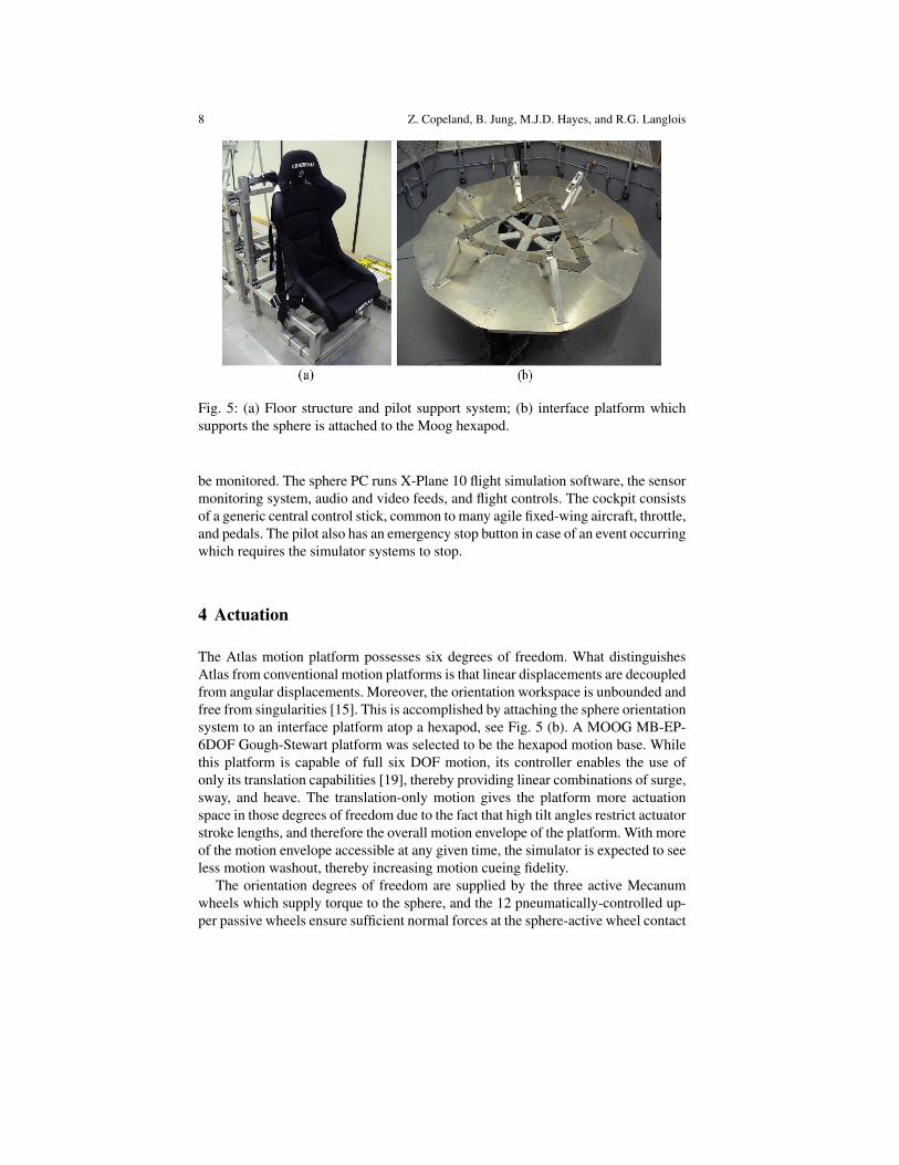
Attached to the internal support structures are the brackets and flooring that pro-vide a base for the cockpit, seen in Fig. 5 (a). Reconfigurability created the demandfor a highly-modular internal structure, so it is bracket and bolt based, allowingfor any single component to be reconfigured without requiring disassembly of thesphere. The flooring support structure interfaces with the stiffeners via four bracketswhich are bolted to them directly.
3 Sphere Internal Electronics
Unbounded rotation necessitates wireless communication and the use of batteries inorder to power the internal electronics of the sphere; LED lighting strips, ventilationfans, environmental sensors, as well as the internal sphere PC. The batteries are re-moved from the sphere to be recharged after each simulation run. The LED lightingstrips are attached to the interior ribs of the sphere, providing illumination for entry,egress, and operation.
While in operation, the interior of the sphere is a closed physical system. Thisrequires that the internal temperature, humidity, CO2 levels, and power levels must
8 Z. Copeland, B. Jung, M.J.D. Hayes, and R.G. Langlois
Fig. 5: (a) Floor structure and pilot support system; (b) interface platform whichsupports the sphere is attached to the Moog hexapod.
be monitored. The sphere PC runs X-Plane 10 flight simulation software, the sensormonitoring system, audio and video feeds, and flight controls. The cockpit consistsof a generic central control stick, common to many agile fixed-wing aircraft, throttle,and pedals. The pilot also has an emergency stop button in case of an event occurringwhich requires the simulator systems to stop.
4 Actuation
The Atlas motion platform possesses six degrees of freedom. What distinguishesAtlas from conventional motion platforms is that linear displacements are decoupledfrom angular displacements. Moreover, the orientation workspace is unbounded andfree from singularities [15]. This is accomplished by attaching the sphere orientationsystem to an interface platform atop a hexapod, see Fig. 5 (b). A MOOG MB-EP-6DOF Gough-Stewart platform was selected to be the hexapod motion base. Whilethis platform is capable of full six DOF motion, its controller enables the use ofonly its translation capabilities [19], thereby providing linear combinations of surge,sway, and heave. The translation-only motion gives the platform more actuationspace in those degrees of freedom due to the fact that high tilt angles restrict actuatorstroke lengths, and therefore the overall motion envelope of the platform. With moreof the motion envelope accessible at any given time, the simulator is expected to seeless motion washout, thereby increasing motion cueing fidelity.
The orientation degrees of freedom are supplied by the three active Mecanumwheels which supply torque to the sphere, and the 12 pneumatically-controlled up-per passive wheels ensure sufficient normal forces at the sphere-active wheel contact
Full-scale Atlas Motion Platform: Structure; Actuation; Control 9
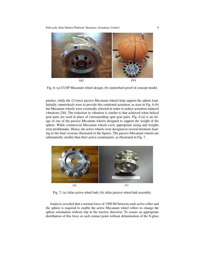
Fig. 6: (a) CUSP Mecanum wheel design; (b) omniwheel proof of concept model.
patches, while the 12 lower passive Mecanum wheels help support the sphere load.Initially, omniwheels were to provide this rotational actuation, as seen in Fig. 6 (b)but Mecanum wheels were eventually selected in order to reduce actuation-inducedvibrations [26]. The reduction in vibration is similar to that achieved when helicalgear pairs are used in place of corresponding spur gear pairs. Fig. 6 (a) is an im-age of one of the passive Mecanum wheels designed to support the weight of thesphere. While commercial Mecanum wheels exist, appropriate sizing and weightswere problematic. Hence, the active wheels were designed in several iterations lead-ing to the final versions illustrated in the figures. The passive Mecanum wheels aresubstantially smaller than their active counterparts, as illustrated in Fig. 7.
Fig. 7: (a) Atlas active wheel hub; (b) Atlas passive wheel hub assembly.
Analysis revealed that a normal force of 1500 lbf between each active roller andthe sphere is required to enable the active Mecanum wheel rollers to change thesphere orientation without slip in the tractive direction. To ensure an appropriatedistribution of this force at each contact point without delamination of the S-glass

10 Z. Copeland, B. Jung, M.J.D. Hayes, and R.G. Langlois
requires that the forces be distributed over an area of at least 2.5 in2, while ensur-ing that the roller material is stiff enough to avoid deflecting to the point that thehubs would abrade the sphere during operation. Urethane was selected because offavourable wear characteristics and strength limits that are adequate for the expectedloading of the Atlas prototype, as well as having a large range of durometers (levelsof compliance) to choose from. Testing was conducted in an MTS press, shown inFig. 8 (a), to establish suitable urethane durometer. Contact patch size was recordedvia an ink stamp test where the roller was compressed onto a sheet of paper andanalyzed photogrammetrically. A sample ink blot can be seen in Fig. 8 (b). This ledto the determination of the effective pressure exerted on the sphere surface.
Fig. 8: (a) MTS press test frame with sample roller inserted; (b) resulting ink blotafter compression testing a durometer 55A urethane to 1300 lbf.
The analysis revealed that the two durometers of urethane considered for testing,55A and 85A, both satisfied the minimum required surface contact patch size of2.5 in2. While the durometer 55A urethane had surface areas in excess of 5 in2,it experienced longitudinal deflections on the order 0.5 in, indicating that it wouldlikely jam and abrade the sphere during torque transmission. For this reason, thedurometer 85A was selected for the rolling surfaces on both the passive and activeMecanum wheels. Operational force limits on the sphere S-glass surface mean thatthe maximum surface pressure is 700 psi. The durometer 85A sample was able tomaintain a safety factor of at least 1.5 over the operable pressure range expected.

Full-scale Atlas Motion Platform: Structure; Actuation; Control 11
5 Control, Dynamics, and Simulation
Motion control of the full-scale Atlas platform is based on control algorithms thathave been developed and refined incrementally and ultimately prototyped and suc-cessfully demonstrated on the half-scale Atlas prototype [29]. Adaptation of the al-gorithms for use on the full-scale Atlas prototype is supported by a dynamic modelto simulate the sphere motions given pilot flight control inputs. The following sec-tions provide a high-level description of the feedback motion control [15], motortorque requirements [21], and the simulated dynamic response of the sphere.
5.1 Control
The role of the overall Atlas control system is to convert the vehicle state informa-tion generated by the on-board vehicle simulation program into deliberate motionsof the Atlas platform such that effective motion cues are provided to the trainee. Acentral element of the controller is a classical washout filter1 that has been extendedto exploit the large angular motions achievable with Atlas. The washout filter mapssimulated vehicle state information to desired translational and rotational motionsof the simulator cockpit. The challenge in doing so is to provide effective motioncueing without exceeding the kinematic bounds of the platform. Due to the novel ar-chitecture of Atlas, there are no angular displacement limits; however, translationaldisplacement limits as well as both angular and translational limits on velocities andaccelerations must be taken into account. The resulting coordinated translationaland rotational motion commands are sent to the translational stage and rotationalstage local controllers, respectively, for the current actuation time step. Transla-tional actuation using the available Stewart-Gough platform actuators is handled bythe commercial translational motion platform controller. Control of the rotationalstage is achieved using a custom control approach.
Fig. 9: Angular motion feedback control loop.
1 Washout filter is alternatively referred to as a tilt-coordination algorithm.
12 Z. Copeland, B. Jung, M.J.D. Hayes, and R.G. Langlois
Fig. 9 provides a high-level block diagram of the rotational stage control archi-tecture. The block labelled Reference Trajectory refers to the rotational componentof the washout algorithm. The output qd is the desired platform pose, which is com-pared with the current measured platform pose qm, as reported by the orientation-sensing system (OS). The resulting difference between the desired and measuredposes e drives a quaternion-based control algorithm that determines the requiredsphere angular velocity ωr. Using inverse kinematics that are analogous to the torqueJacobian presented in the following section, the required speeds of the three indi-vidual active Mecanum wheels Ωr can be determined. These are then producedusing the individual wheel local motor drive controllers that regulate motor torqueto achieve desired speeds. This, in turn, produces the angular motion of the Atlassphere; which, when combined with the translational motion, creates the desiredmotion cues for the pilot.
5.2 Sphere Orientation Sensing
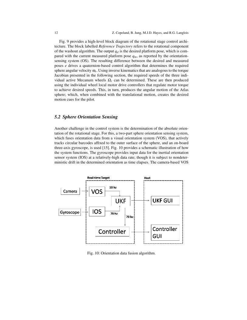
Another challenge in the control system is the determination of the absolute orien-tation of the rotational stage. For this, a two-part sphere orientation sensing system,which fuses orientation data from a visual orientation system (VOS), that activelytracks circular barcodes affixed to the outer surface of the sphere, and an on-boardthree-axis gyroscope, is used [15]. Fig. 10 provides a schematic illustration of howthe system functions. The gyroscope provides input data for the inertial orientationsensor system (IOS) at a relatively-high data rate; though it is subject to nondeter-ministic drift in the determined orientation as time elapses. The camera-based VOS
Fig. 10: Orientation data fusion algorithm.

Full-scale Atlas Motion Platform: Structure; Actuation; Control 13
system offers the complementary advantage of being able to measure the absoluteorientation of the sphere; though at a much lower data rate than the IOS due to thetime required for image processing. Using an Unscented Kalman Filter (UKF) theorientation data can be effectively fused resulting in high-rate, robust, and reliableorientation data that is not subject to drift. This system comprises the block labelledOS in Fig. 9.
5.3 CUSP Simple Infrastructure
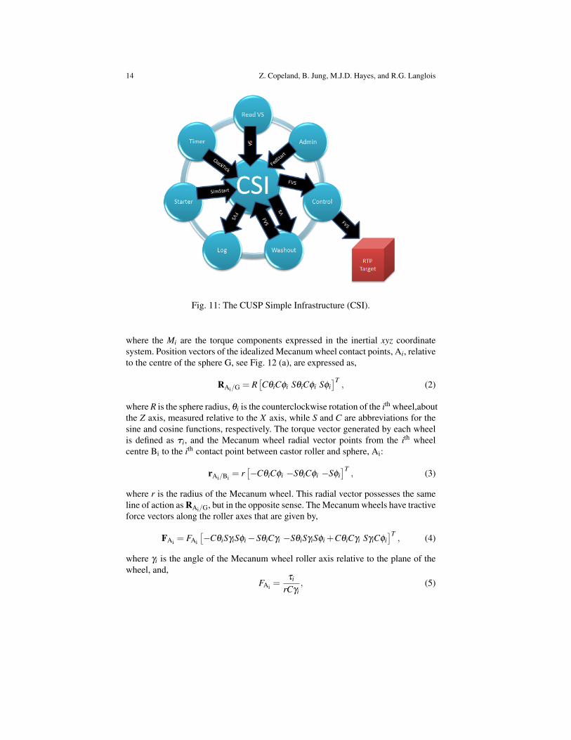
Each individual simulation subsystem is managed by a federate program in chargeof handling the communication between subsystems and running the necessary con-trol calculations. Core federates directly related to the control of major simulatoroperations include the ReadVS federate, Control federate, and Washout federate.Vehicle state data is read from the flight simulation software by the ReadVS feder-ate, while the Washout federate splits this state data into high- and low-frequencyaccelerations. The Control federate then sends the filtered vehicle state data to theRTP Target which runs the IOS/VOS tracking program and motor controls. Eachfederate program publishes information over the network via UDP where the datamay be read by other programs if they are subscribers.
The CUSP Simple Infrastructure (CSI) is the custom architecture that binds thevarious federates together, facilitating the data exchange between the federates onthe network, and is illustrated in Fig. 11. The network architecture supports bothwired and wireless communication such that computing resources located insidethe sphere can communicate seamlessly with computing resources located outsidethe sphere without requiring and umbilical cable for data transfer. The CSI is com-posed of a dynamically linked library that is on each machine running a federateprogram and the executable that manages data traffic between federates. A propri-etary markup language, similar to XML, enables changes to be made to what data isbeing sent and received. Federates may subscribe in real-time to any other federate.
5.4 Torque Jacobian and Simulated Dynamic Response
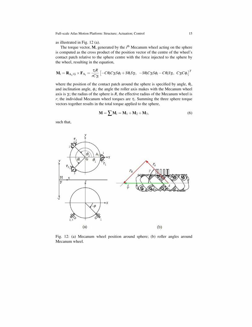
The three motors that actuate each of the active Mecanum wheels are positionedequilaterally around the sphere’s vertical axis and 45 degrees below the equator, in-dicated by φ =−45 for all three wheels, as illustrated in Fig. 12 (a). The Mecanumwheel castor rollers are oriented at a 45 degree angle relative to the Mecanum wheelaxis of rotation, γ =−45 for all rollers, as indicated in Fig. 12 (b).
The total torque M generated by the Mecanum wheels acting on the sphere isexpressed in vector notation as,
M =[MX MY MZ
]T, (1)
14 Z. Copeland, B. Jung, M.J.D. Hayes, and R.G. Langlois
Fig. 11: The CUSP Simple Infrastructure (CSI).
where the Mi are the torque components expressed in the inertial xyz coordinatesystem. Position vectors of the idealized Mecanum wheel contact points, Ai, relativeto the centre of the sphere G, see Fig. 12 (a), are expressed as,
RAi/G = R[CθiCφi SθiCφi Sφi
]T, (2)
where R is the sphere radius, θi is the counterclockwise rotation of the ith wheel,aboutthe Z axis, measured relative to the X axis, while S and C are abbreviations for thesine and cosine functions, respectively. The torque vector generated by each wheelis defined as τi, and the Mecanum wheel radial vector points from the ith wheelcentre Bi to the ith contact point between castor roller and sphere, Ai:
rAi/Bi= r[−CθiCφi −SθiCφi −Sφi
]T, (3)
where r is the radius of the Mecanum wheel. This radial vector possesses the sameline of action as RAi/G, but in the opposite sense. The Mecanum wheels have tractiveforce vectors along the roller axes that are given by,
FAi = FAi
[−CθiSγiSφi−SθiCγi −SθiSγiSφi +CθiCγi SγiCφi
]T, (4)
where γi is the angle of the Mecanum wheel roller axis relative to the plane of thewheel, and,
FAi =τi
rCγi, (5)
Full-scale Atlas Motion Platform: Structure; Actuation; Control 15
as illustrated in Fig. 12 (a).The torque vector, M, generated by the ith Mecanum wheel acting on the sphere
is computed as the cross product of the position vector of the centre of the wheel’scontact patch relative to the sphere centre with the force injected to the sphere bythe wheel, resulting in the equation,
Mi = RAi/G×FAi =τiRrCγi
[−CθiCγiSφi +SθiSγi, −SθiCγiSφi−CθiSγi, CγiCφi
]Twhere the position of the contact patch around the sphere is specified by angle, θi,and inclination angle, φi; the angle the roller axis makes with the Mecanum wheelaxis is γi; the radius of the sphere is R, the effective radius of the Mecanum wheel isr; the individual Mecanum wheel torques are τi. Summing the three sphere torquevectors together results in the total torque applied to the sphere,
M = ∑Mi = M1 +M2 +M3, (6)
such that,
Fig. 12: (a) Mecanum wheel position around sphere; (b) roller angles aroundMecanum wheel.
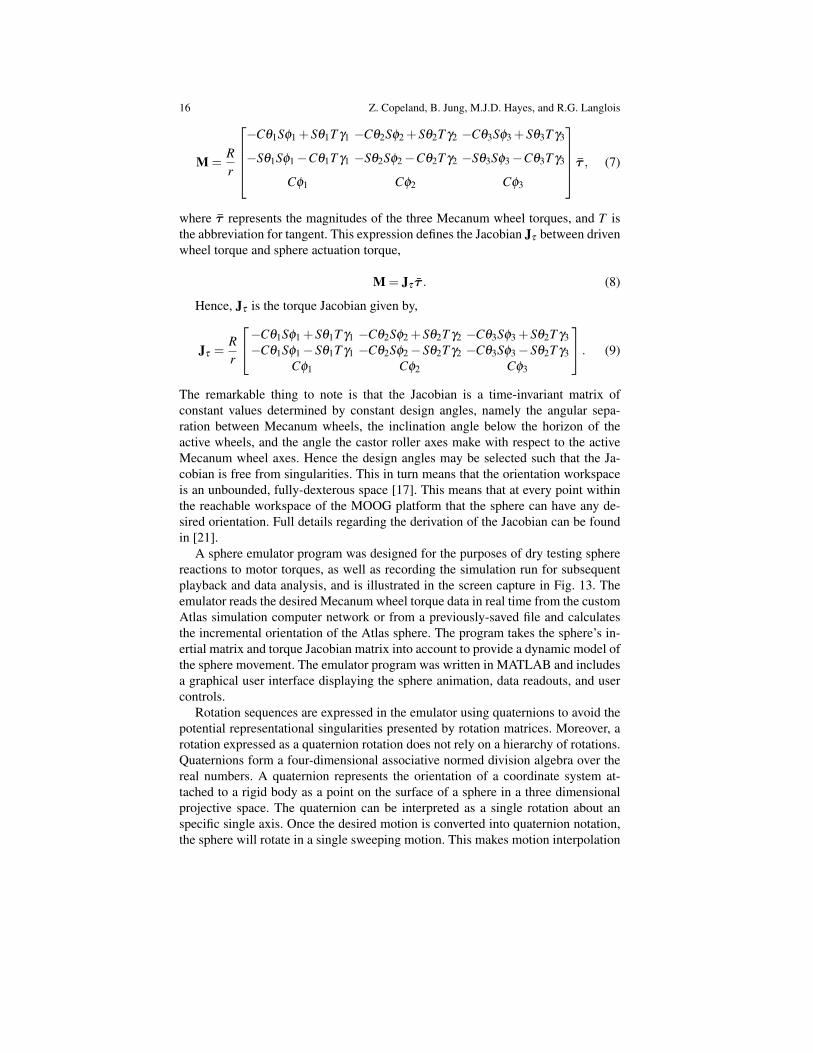
16 Z. Copeland, B. Jung, M.J.D. Hayes, and R.G. Langlois
M =Rr
−Cθ1Sφ1 +Sθ1T γ1 −Cθ2Sφ2 +Sθ2T γ2 −Cθ3Sφ3 +Sθ3T γ3
−Sθ1Sφ1−Cθ1T γ1 −Sθ2Sφ2−Cθ2T γ2 −Sθ3Sφ3−Cθ3T γ3
Cφ1 Cφ2 Cφ3
τ , (7)
where τ represents the magnitudes of the three Mecanum wheel torques, and T isthe abbreviation for tangent. This expression defines the Jacobian Jτ between drivenwheel torque and sphere actuation torque,
M = Jτ τ . (8)
Hence, Jτ is the torque Jacobian given by,
Jτ =Rr
−Cθ1Sφ1 +Sθ1T γ1 −Cθ2Sφ2 +Sθ2T γ2 −Cθ3Sφ3 +Sθ2T γ3−Cθ1Sφ1−Sθ1T γ1 −Cθ2Sφ2−Sθ2T γ2 −Cθ3Sφ3−Sθ2T γ3
Cφ1 Cφ2 Cφ3
. (9)
The remarkable thing to note is that the Jacobian is a time-invariant matrix ofconstant values determined by constant design angles, namely the angular sepa-ration between Mecanum wheels, the inclination angle below the horizon of theactive wheels, and the angle the castor roller axes make with respect to the activeMecanum wheel axes. Hence the design angles may be selected such that the Ja-cobian is free from singularities. This in turn means that the orientation workspaceis an unbounded, fully-dexterous space [17]. This means that at every point withinthe reachable workspace of the MOOG platform that the sphere can have any de-sired orientation. Full details regarding the derivation of the Jacobian can be foundin [21].
A sphere emulator program was designed for the purposes of dry testing spherereactions to motor torques, as well as recording the simulation run for subsequentplayback and data analysis, and is illustrated in the screen capture in Fig. 13. Theemulator reads the desired Mecanum wheel torque data in real time from the customAtlas simulation computer network or from a previously-saved file and calculatesthe incremental orientation of the Atlas sphere. The program takes the sphere’s in-ertial matrix and torque Jacobian matrix into account to provide a dynamic model ofthe sphere movement. The emulator program was written in MATLAB and includesa graphical user interface displaying the sphere animation, data readouts, and usercontrols.
Rotation sequences are expressed in the emulator using quaternions to avoid thepotential representational singularities presented by rotation matrices. Moreover, arotation expressed as a quaternion rotation does not rely on a hierarchy of rotations.Quaternions form a four-dimensional associative normed division algebra over thereal numbers. A quaternion represents the orientation of a coordinate system at-tached to a rigid body as a point on the surface of a sphere in a three dimensionalprojective space. The quaternion can be interpreted as a single rotation about anspecific single axis. Once the desired motion is converted into quaternion notation,the sphere will rotate in a single sweeping motion. This makes motion interpolation

Full-scale Atlas Motion Platform: Structure; Actuation; Control 17
Fig. 13: The Atlas Emulator user interface.
between large angle rotations possible. Quaternion algebra and use as a rotation op-erator is found in in many texts, see [6, 16] for example. The quaternion can beexpressed as
q = q0 + iq1 + jq2 +kq3. (10)
It comprises a scalar part, q0, and a vector part, q1, q2, and q3:
q0 = cos(α/2) ;q1 = sin(α/2)cos(βx) ;q2 = sin(α/2)cos(βy) ;q3 = sin(α/2)cos(βz) ;
(11)

18 Z. Copeland, B. Jung, M.J.D. Hayes, and R.G. Langlois
where α is the rotation angle, and the βi is the direction cosines of the rotation axis.Changes in orientation requires quaternion products between the initial and finalorientations. A quaternion product has the form
q · p = Q(p) ·q, (12)
where,
Q(p) =
q0 −q1 −q2 −q3q1 q0 −q3 q2q2 q3 q0 −q1q3 −q2 q1 q0
. (13)
The moment of inertia matrix, I, necessary for dynamic modelling was extractedfrom the Atlas composite CAD model by estimating the approximate densities ofeach component in the assembly. This is a 3 x 3 symmetric matrix that is variableto accommodate changes to the sphere weight distribution between simulation runs.For each simulation cycle, the initial motor torque, angular rate, and sphere attitude(τ,ω0,φ0) are read by the emulator and then converted to quaternions which aredenoted e0.
The angular momentum equation can be rearranged as
α1 = I−1 (M−ω0× Iω0) , (14)
where α is the sphere angular acceleration. The angular acceleration is numericallyintegrated resulting in an updated angular velocity:
ω1 = ω0 +∫
α1dt. (15)
The Euler angle rates are converted to quaternion rates yielding [6]
e1 =12
Lω1, (16)
where
L =
−q1 q0 −q3 q2−q2 q3 q0 −q1−q3 −q2 q1 −q0
. (17)
The quaternion rate is then numerically integrated to obtain an updated orienta-tion:
e1 = e0 +∫
e1dt. (18)

Full-scale Atlas Motion Platform: Structure; Actuation; Control 19
Finally the quaternion rate is converted back into Euler angle rates. The calculatedangular rate and angle are then fed back into the system for the next iteration,e1→ φ1. This process is then repeated for the duration of the dynamic simulation.
6 Concluding Remarks
This paper has presented an overview of the current state of development of the At-las simulator motion base with emphasis on the rotational actuation system, as wellas computational tools that have been developed to support the design and operationof the system. As is apparent from the design, the unusual actuation method providesunique motion capabilities for the simulator: most notably unbounded, singularity-free rotation. However, with that come some practical challenges relating to the needfor tether-free power, data transfer, and ventilation. As described, these issues wereresolved early in the overall simulator design cycle such that their solutions couldbe incorporated into the detailed design of Atlas. A power-conscious electrical de-sign has allowed the sphere internal systems to be run from a rechargeable batterypower source located inside the sphere. Data transfer is enabled using a wirelessprotocol for communicating the vehicle state information and various sensor mea-surements out of the sphere as well as various simulation control signals into thesphere. Running the main vehicle simulation on the sphere PC (located inside thesphere) precludes the need for transmitting bandwidth-intensive simulation audioand video streams over the wireless network. Ventilation is provided using forcedconvection through the sphere generated by eight hatch-mounted fans. Additionally,since the drive system is unconventional and relies on technologies for which exactclosed-form solutions do not exist in many cases, and despite the fact that the basicdesign principles are low risk, it is anticipated that much will be learned through thecommissioning and calibration phases of the full-scale prototype.
Three related areas of particular interest will be the contact forces, Mecanumwheel tractive forces, and wheel slip. In total, the sphere is held in place by patchcontact with 27 Mecanum wheels. The system is clearly statically indeterminate andtime-varying due to the inertial loads acting on the system as the simulator is in mo-tion and also due to the time-varying tractive forces applied by the active Mecanumwheels. Design tools that were developed to approximate the worst-case contactforces necessarily made assumptions: such as the relative rigidity of the externalsupporting structure; the effective stiffnesses of both the small and large Mecanumwheel castor assemblies; and the characteristics of urethane in this application. Themaximum tractive effort of the active Mecanum wheels will depend both on theprevailing contact forces and the friction characteristics at the interface between theactive Mecanum wheels and sphere surface. Initial testing was performed to deter-mine the required durometer of urethane and its friction properties; however, somenotable differences between test conditions and in situ operation are anticipated. Fi-nally, wheel slip due to tangential compression of the urethane material prior to itentering the active Mecanum wheel contact patches is expected to result in longi-
20 Z. Copeland, B. Jung, M.J.D. Hayes, and R.G. Langlois
tudinal slip, similar to what occurs with pneumatic tires. The extent of this and itsimpact on the idealized kinematic equations, based upon which the system has beendesigned, will have to be assessed and integrated into the Atlas control system.
As a result of its unique design, the Atlas simulator, as described in this paper,introduces a significant technical innovation in the ability to generate large angularmotions with a simulator motion base. It also presents numerous opportunities forfurther research and development by the authors and the broader research commu-nity.
References
1. Akdag, M., Karagulle, H., Malgaca, L.: An integrated approach for simulation of mechatronicsystems applied to a hexapod robot. Mathematics and computers in simulation 82(5), 818–835(2012)
2. Angeles, J.: Fundamentals of Robotic Mechanical Systems: Theory, Methods, and Algorithms.Springer-Verlag, New York, N.Y., U.S.A. (1997)
3. Bles, W., Groen, E.: The DESDEMONA Motion Facility: Applications for Space Research.Microgravity Science and Technology 21(4), 281–286 (2009)
4. Chirikjian, G.S., Stein, D.: Kinematic Design and Commutation of a Spherical Stepper Motor.IEEE/ASME Transactions on Mechatronics 4(4), 342–353 (1999)
5. Dickerson, S.L., Lapin, B.D.: Control of an Omni-directional Robotic Vehicle With MecanumWheels. Computer Aided Geometric Design 25(9), 784–791 (1991)
6. Diebel, J.: Representing Attitude: Euler Angles, unit Quaternions, and Rotation Vectors. Stan-ford University (October 2006)
7. Gawron, V.J., Bailey, R., Lehman, E.: Lessons Learned in Applying Simulators to CrewstationEvaluation. International Journal of Aviation Psychology vol. 5, no. 2, 277–290 (1995)
8. Gfrerrer, A.: Geometry and Kinematics of the Mecanum Wheel. Computer Aided GeometricDesign 25(9), 784–791 (2008)
9. Gough, V.E.: Discussion in London: Automobile Stability, Control, and Tyre Performance.Proc. Automobile Division, Institution of Mech. Engrs. pp. 392–394 (1956)
10. Hayes, M.J.D., Langlois, R.G.: Atlas: a Novel Kinematic Architecture for Six DOF MotionPlatforms. Transaction of the Canadian Society for Mechanical Engineering 29(4), 701–709(2005)
11. Husty, M.: An Algorithm for Solving the Direct Kinematics of General Stewart-Gough Plat-forms. Mechanism and Machine Theory vol. 31, no. 4, pages 365–379 (1996)
12. Ilon, B.E.: Control of an Omni-directional Robotic Vehicle With Mecanum Wheels. US Patent3876255 (April 1975)
13. Jonsson, S.: New AGV with Revolutionary Movement. Proc. 3rd Int. Conf. on AutomatedGuided Vehicles, edited by S. E. Anderson Stockholm pp. 135–144 (1985)
14. Kim, J., Hwang, J.C., Kim, J.S., Iurascu, C., Park, F.C., Cho, Y.M.: Eclipse-11: a New Par-allel Mechanism Enabling Continuous 360-Degree Spinning Plus Three-axis TranslationalMotions. IEEE Transactions on Robotics and Automation 18(3), 367–373 (2002)
15. Klumper, K., Morbi, A., Chisholm, K.J., Beranek, R., Ahmadi, M., Langlois, R.G.: OrientationControl of Atlas: A Novel Motion Simulation Platform. No. 13-CSME-192, E.I.C. Accession3650 (September 2013)
16. Kuipers, J.B.: Quaternions and Rotation Sequences. Princeton university press, Princeton,N.J., U.S.A. (1999)
17. Kumar, A.V., Waldron, K.J.: The Workspace of a Mechanical Manipulator. ASME Journal ofMechanical Design 103(3), 665–672 (1981)
Full-scale Atlas Motion Platform: Structure; Actuation; Control 21
18. Leow, Y.P., Low, K.H., Loh, W.K.: Kinematic Modelling and Analysis of Mobile Robotswith Omni-directional Wheels. Seventh International Conference on Control, Automation,Robotics and Vision (ICARCV’02), Singapore pp. 820–825 (Dec. 2002)
19. Moog Inc.: Moog Motion Systems Overview (2009). Rev 3.11.0920. Muir, P.F., Neuman, C.P.: Kinematic Modeling for Feedback Control of an Omnidirection
Wheeled Mobile Robot. IEEE Intenational Conference on Robotics and Automation 25(9),784–791 (1987)
21. Plumpton, J.J., Hayes, M.J.D., Langlois, R.G., Burlton, B.V.: Atlas Motion Platform MecanumWheel Jacobian in the Velocity and Static Force Domains. No. 13-CSME-192, E.I.C. Acces-sion 3650 (September 2013)
22. Roth, R.B., Lee, K.M.: Design Optimization of a Three-Degree-of-Freedom Variable Reluc-tance Spherical Wrist Motor. ASME J. Eng. Industry 117, 378–388 (1995)
23. Salih, J.E.M., Rizon, M., Yaacob, S., Adom, A.H., Mamat, M.R.: Designing omni-directionalmobile robot with mecanum wheel. American Journal of Applied Sciences 3(5), 1831–1835(2006)
24. Schaetzle, S., Preusche, C., Hirzinger, G.: Workspace optimization of the robocoaster used as amotion simulator. In: Proceedings of the 14th IASTED International Conference on Roboticsand Applications, vol. 1, pp. 470–477 (2009)
25. Stewart, D.: A Platform With Six Degrees of Freedom. Proc. Instn. Mech. Engr. 180(15),371–378 (1965)
26. Weiss, A., Langlois, R.G., Hayes, M.J.D.: Dynamics and Vibration Analysis of the InterfaceBetween a Non-rigid Sphere and Omnidirectional Wheel Actuators. Robotica (May 2014)
27. Williams, F., Laithwaite, E.R., Eastham, G.F.: Development and Design of Spherical InductionMotors. Proc. IEEE 47, 471–484 (1959)
28. Williams, R., Carter, D., Gallina, P., Rosati, G.: Dynamics Model with Slip for Wheeled Omni-Directional Robots. IEEE Transactions on Robotic and Automation vol. 18, no. 3, 285–293(2002)
29. Zhou, S.: Sensing and vision-based control of a spherical motion platform. M.A.Sc. thesis,Carleton University, Ottawa, Canada (2013)