full size chevy stock height disc brake kit instructions / or during installation of disc conversion...
TRANSCRIPT
Installation Instructions for PART # 630080; 630085; 630095; 630096
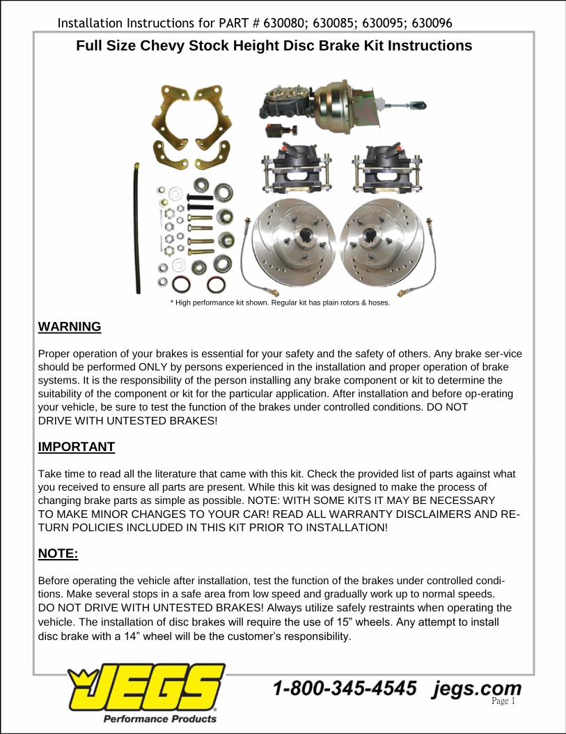
Full Size Chevy Stock Height Disc Brake Kit Instructions
* High performance kit shown. Regular kit has plain rotors & hoses.
WARNING Proper operation of your brakes is essential for your safety and the safety of others. Any brake ser-vice
should be performed ONLY by persons experienced in the installation and proper operation of brake
systems. It is the responsibility of the person installing any brake component or kit to determine the
suitability of the component or kit for the particular application. After installation and before op-erating
your vehicle, be sure to test the function of the brakes under controlled conditions. DO NOT DRIVE WITH UNTESTED BRAKES!
IMPORTANT Take time to read all the literature that came with this kit. Check the provided list of parts against what
you received to ensure all parts are present. While this kit was designed to make the process of
changing brake parts as simple as possible. NOTE: WITH SOME KITS IT MAY BE NECESSARY TO MAKE MINOR CHANGES TO YOUR CAR! READ ALL WARRANTY DISCLAIMERS AND RE- TURN POLICIES INCLUDED IN THIS KIT PRIOR TO INSTALLATION!
NOTE: Before operating the vehicle after installation, test the function of the brakes under controlled condi-
tions. Make several stops in a safe area from low speed and gradually work up to normal speeds. DO NOT DRIVE WITH UNTESTED BRAKES! Always utilize safely restraints when operating the
vehicle. The installation of disc brakes will require the use of 15” wheels. Any attempt to install
disc brake with a 14” wheel will be the customer’s responsibility. Page 1
Page 2

Installation Instructions for PART # 630080; 630085; 630095; 630096
Preparing your vehicle to install your brake system upgrade
1. Rack the vehicle. 2. If you don’t have a rack, then you must take extra safety precautions. 3. Choose a firmly packed and level ground to jack up the vehicle. 4. Chock the rear wheels. 5. Jack the vehicle up and support it with jack stands and secure the pins. 6. Set the parking brake and put the transmission in park if automatic, reverse if
manual transmission.
7. The front wheels should be allowed to free hang to relieve tension on the coil springs.
Remember: NEVER rely on jacks to support a vehicle! Always test the steadiness of your
stands that are supporting the vehicle before attempting to work on a raised vehicle!
Preparing your parts
1. Locate the spindles and the inner wheel bearings. In order to install the inner bearings on new
spindles, often you must remove .0004” from the inner bearing seating diameter. This can be
accomplished with 240 grit emery paper and a rotary sanding motion on the spindle. Be sure to
sand around the radius of the spindle which avoids flat spots. Continue this operation until the
inner bearings can be slid onto the spindle without binding. Remember to use brake parts cleaner
to keep all surfaces free of debris. Also use a lubricant such as bearing grease to ease them on.
Do not grind or file on the spindle!
2. Pack all bearings with hi-temp wheel bearing grease. A bearing packing tool is ideal for the
job. (See Figure 1)
3. Adhere the brake pads into place using disc brake quiet and bend outer brake tabs over
calipers accordingly. Let them cure!
4. Mate up each threaded nut with its’ designated bolt or threaded surface. 5. Group your kit parts to speed up the installation. 6. Check your quantity of components versus the items list.
Fig
ure
1
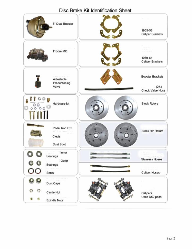
Components to inspect, replace or upgrade prior to Universal Bearing Packer
And / or during installation of disc conversion kits
Tie rod ends and nuts Adjustment sleeves Control arm shafts, mounting bolts, & nuts
Control Arms Idler arm and nut Pitman Arm and nut
Upper Ball Joints and nuts Lower Ball Joints and nuts Shocks and hardware
Residual valves Metering valves Proportioning valves
Brake lines Stainless steel brake lines Stainless steel hardware
Page 3
Installation Instructions for PART # 630080; 630085; 630095; 630096
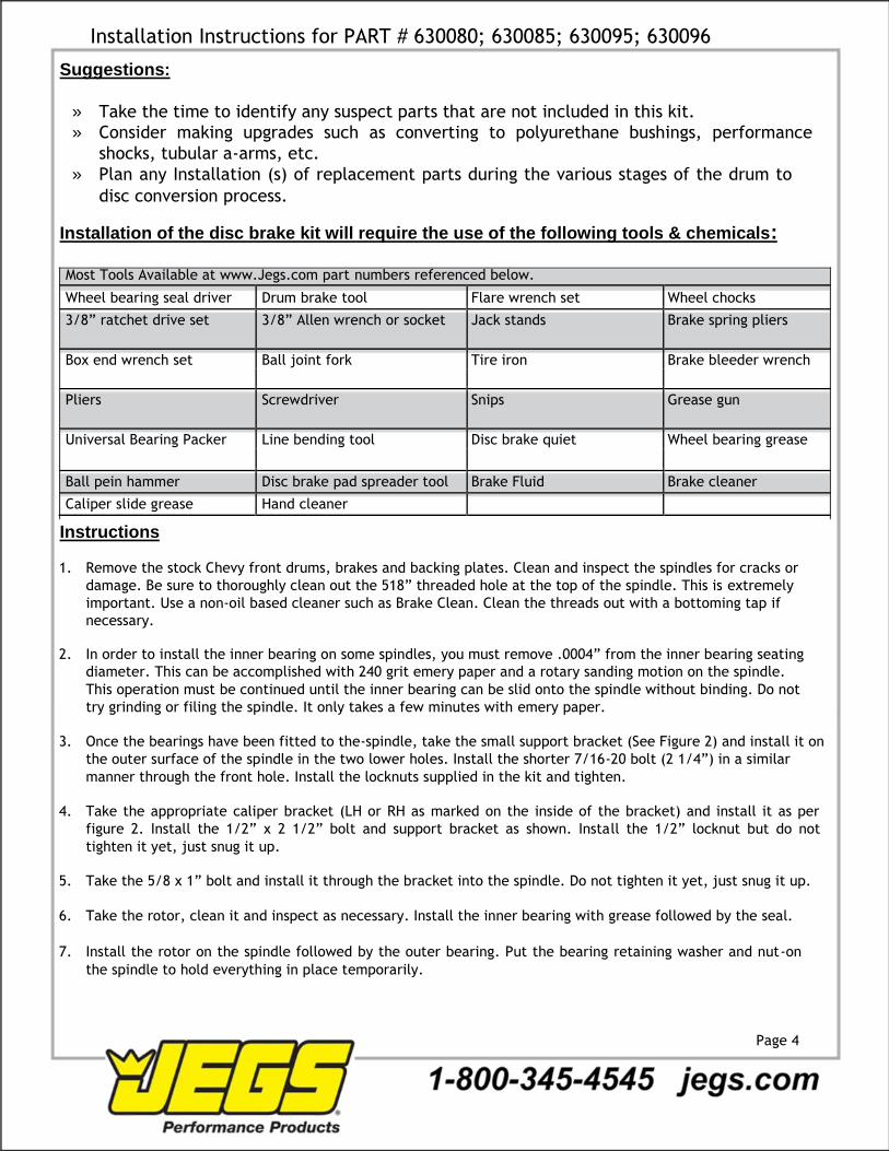
Suggestions:
» Take the time to identify any suspect parts that are not included in this kit. » Consider making upgrades such as converting to polyurethane bushings, performance
shocks, tubular a-arms, etc.
» Plan any Installation (s) of replacement parts during the various stages of the drum to
disc conversion process.
Installation of the disc brake kit will require the use of the following tools & chemicals:
Most Tools Available at www.Jegs.com part numbers referenced below.
Wheel bearing seal driver Drum brake tool Flare wrench set Wheel chocks
3/8” ratchet drive set 3/8” Allen wrench or socket Jack stands Brake spring pliers
Box end wrench set Ball joint fork Tire iron Brake bleeder wrench
Pliers Screwdriver Snips Grease gun
Universal Bearing Packer Line bending tool Disc brake quiet Wheel bearing grease
Ball pein hammer Disc brake pad spreader tool Brake Fluid Brake cleaner
Caliper slide grease Hand cleaner
Instructions 1. Remove the stock Chevy front drums, brakes and backing plates. Clean and inspect the spindles for cracks or
damage. Be sure to thoroughly clean out the 518” threaded hole at the top of the spindle. This is extremely
important. Use a non-oil based cleaner such as Brake Clean. Clean the threads out with a bottoming tap if
necessary.
2. In order to install the inner bearing on some spindles, you must remove .0004” from the inner bearing seating
diameter. This can be accomplished with 240 grit emery paper and a rotary sanding motion on the spindle.
This operation must be continued until the inner bearing can be slid onto the spindle without binding. Do not
try grinding or filing the spindle. It only takes a few minutes with emery paper.
3. Once the bearings have been fitted to the-spindle, take the small support bracket (See Figure 2) and install it on
the outer surface of the spindle in the two lower holes. Install the shorter 7/16-20 bolt (2 1/4”) in a similar
manner through the front hole. Install the locknuts supplied in the kit and tighten.
4. Take the appropriate caliper bracket (LH or RH as marked on the inside of the bracket) and install it as per
figure 2. Install the 1/2” x 2 1/2” bolt and support bracket as shown. Install the 1/2” locknut but do not
tighten it yet, just snug it up.
5. Take the 5/8 x 1” bolt and install it through the bracket into the spindle. Do not tighten it yet, just snug it up.
6. Take the rotor, clean it and inspect as necessary. Install the inner bearing with grease followed by the seal.
7. Install the rotor on the spindle followed by the outer bearing. Put the bearing retaining washer and nut-on
the spindle to hold everything in place temporarily.
Page 4

Installation Instructions for PART # 630080; 630085; 630095; 630096
Figure 2
8. Turn the rotor on the spindle and check for any interference or minimal clearance between the inside
surface of the rotor and the attaching hardware.
9. When you have adequate clearance, make sure the threads in the spindle are clean. Install the bolt, tighten it
and the 1/2” bolt previously installed.
Figure 3 Page 5
Installation Instructions for PART # 630080; 630085; 630095; 630096
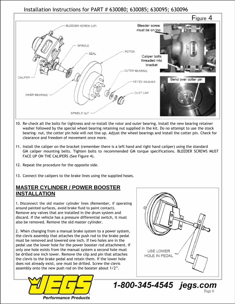
Figure 4 10. Re-check all the bolts for tightness and re-install the rotor and outer bearing. Install the new bearing retainer
washer followed by the special wheel bearing retaining nut supplied in the kit. Do no attempt to use the stock
bearing- nut, the cotter pin hole will not line up. Adjust the wheel bearings and install the cotter pin. Check for
clearance and freedom of movement once more.
11. Install the caliper on the bracket (remember there is a left hand and right hand caliper) using the standard
GM caliper mounting belts. Tighten bolts to recommended GM torque specifications. BLEEDER SCREWS MUST
FACE UP ON THE CALIPERS (See Figure 4).
12. Repeat the procedure for the opposite side.
13. Connect the calipers to the brake lines using the supplied hoses.
MASTER CYLINDER / POWER BOOSTER INSTALLATION 1. Disconnect the old master cylinder lines (Remember, if operating
around painted surfaces, avoid brake fluid to paint contact).
Remove any valves that are installed in the drum system and
discard. If the vehicle has a pressure differential switch, it must
also be removed. Remove the old master cylinder.
2. When changing from a manual brake system to a power system,
the clevis assembly that attaches the push rod to the brake pedal
must be removed and lowered one inch. If two holes are in the
pedal use the lower hole for the power booster rod attachment. If
only one hole exists from the manual system a second hole must
be drilled one inch lower. Remove the clip and pin that attaches
the clevis to the brake pedal and retain them. If the lower hole
does not already exist, one must be drilled. Screw the clevis
assembly onto the new push rod on the booster about 1/2”.
Page 6
Installation Instructions for PART # 630080; 630085; 630095; 630096 3. Mount the booster to the fire-wall with the existing studs or bolts. Place the clevis assembly into the lower hole
in the pedal and install the pin and clip.
4. Install the proper fitting into the intake manifold for vacuum. Connect the vacuum hose from the engine to
the power booster. YOU WILL NEED AT LEAST 18” VACUUM TO OPERATE A BOOSTER.
5. Bench bleed the master cylinder with the supplied bleeder kit.
6. Install the master cylinder onto the booster.
7. Flush out the old brake fluid and replace with DOT 4.
8. Bleed the entire system starting at the wheel farthest from the master cylinder. Check the pedal feel for
firmness. Adjust the clevis so there is 1/4” free play at the pedal stop. If pedal is spongy, bleed again.
NOTE: If you are installing disc brakes without a power booster just mount the manual master to the fire-wall on the
two studs that line up with the large hole. Attach the manual brake push rod to the pedal in the upper hole and
adjust it so that it seats into the piston hole without applying pressure to the piston while at rest.
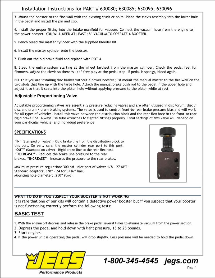
Adjustable Proportioning Valve
Adjustable proportioning valves are essentially pressure reducing valves and are often utilized in disc/drum, disc /
disc and drum / drum braking systems. The valve is used to control front-to-rear brake pressure bias and will work
for all types of vehicles. Install this valve between the distribution block and the rear flex hose in the front-to rear
rigid brake line. Always use tube wrenches to tighten fittings properly. Final settings of this valve will depend on
your par-ticular vehicle, and individual preference.
SPECIFICATIONS
“IN” (Stamped on valve) – Rigid brake line from the distribution block to
this port. On early cars: the master cylinder rear port to this port.
“OUT” (Stamped on valve) – Rigid brake line to the rear flex hose.
“DECREASE” – Reduces the brake line pressure to the rear
brakes. “INCREASE” – Increases the pressure to the rear brakes.
Maximum pressure regulation: 300 psi. Inlet port of valve: 1/8 – 27 NPT Standard adaptors: 3/8” – 24 for 3/16” line. Mounting hole diameter: .250” (two).
WHAT TO DO IF YOU SUSPECT YOUR BOOSTER IS NOT WORKING
It is rare that one of our kits will contain a defective power booster but if you suspect that your booster
is not functioning correctly perform the following tests:
BASIC TEST 1. With the engine off depress and release the brake pedal several times to eliminate vacuum from the power section. 2. Depress the pedal and hold down with light pressure, 15 to 25 pounds. 3. Start engine. 4. If the power unit is operating the pedal will drop slightly. Less pressure will be needed to hold the pedal down.
Page 7
Installation Instructions for PART # 630080; 630085; 630095; 630096
IF BOOSTER IS NOT OPERATING (GIVING A VERY HARD PEDAL)
1. Disconnect the vacuum hose from the booster check valve and check the vacuum level at this point
with the engine running with a vacuum gauge. You should have at least 18” vacuum to the booster.
Anything lower will begin to give a hard pedal. lf the vacuum level is below 18” you may be able to tune
the engine and bring the vacuum level up to that level. If the vacuum level is around 16” the addition of
a vacuum reserve canister will improve the braking. If the vacuum level is below 16” you will need to
add an electric vacuum assist pump to supplement the engine vacuum.
2. If the vacuum level at the check valve is 18” check that the booster check valve is working.
Disconnect the vacuum hose at the check valve and attach a piece of tubing. Blow into the valve. If air
passes through the valve is defective and must be replaced. Also look into the hose attachment neck on
the check valve and be sure there is no obstruction inside the valve.
3. Check your booster for a vacuum leak. With everything hooked up run the engine at moderate speed.
Release the accelerator and turn the engine off. Wait 90 seconds and apply the brakes. If the brake
applications are power assisted there is no leak. If there is no power assist the booster is defective and
must be replaced.
IF THE BOOSTER IS OPERATING BUT YOU STILL HAVE A HARD PEDAL
1. Your combination valve may have tripped shutting off fluid flow to the front or rear brakes. This
condition will produce a very hard pedal. Check that fluid passes through the valve to both the front and
rear by cracking a bleeder screw and observing a good flow of fluid. If one half of the system does hot
have flow, re-center the valve.
2. You may have frozen rear wheel cylinders or frozen caliper pistons. If these components freeze you
can get a very hard pedal.
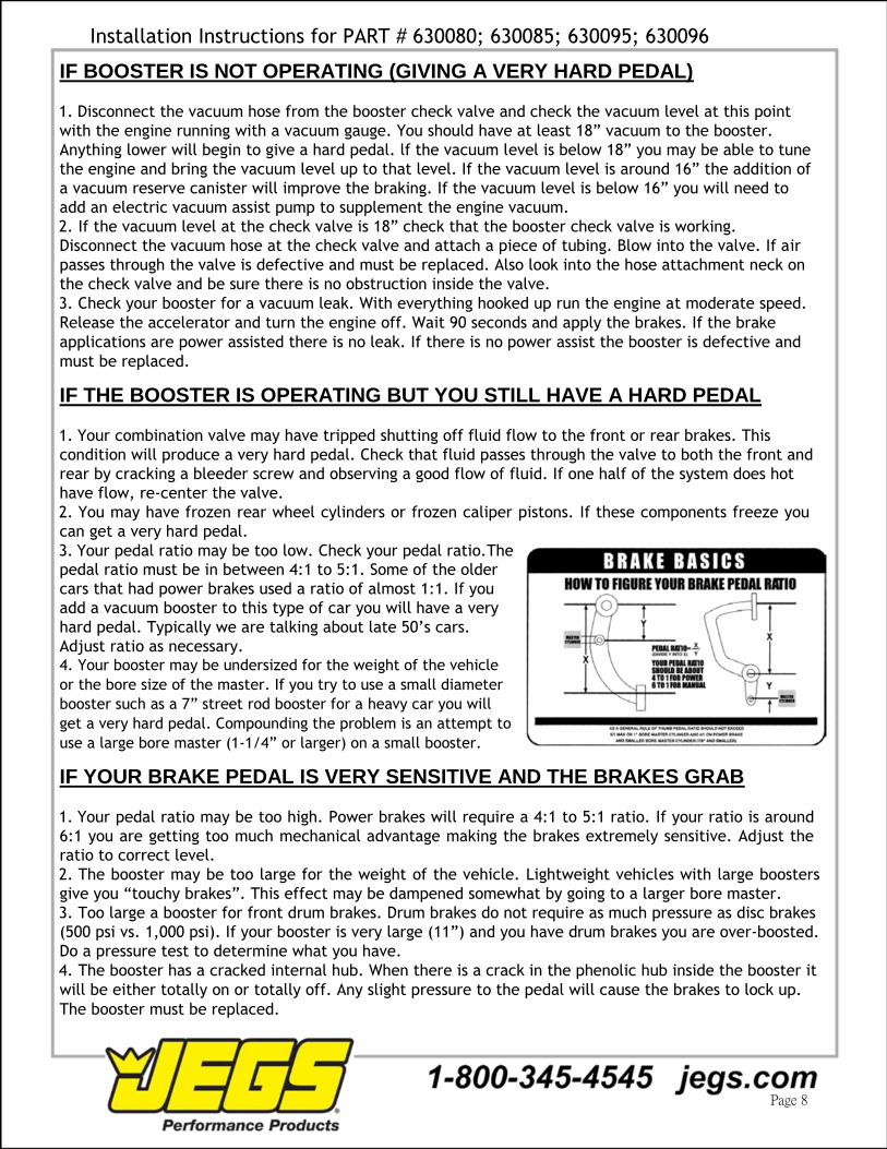
3. Your pedal ratio may be too low. Check your pedal ratio.The pedal ratio must be in between 4:1 to 5:1. Some of the older
cars that had power brakes used a ratio of almost 1:1. If you
add a vacuum booster to this type of car you will have a very
hard pedal. Typically we are talking about late 50’s cars.
Adjust ratio as necessary. 4. Your booster may be undersized for the weight of the vehicle
or the bore size of the master. If you try to use a small diameter
booster such as a 7” street rod booster for a heavy car you will
get a very hard pedal. Compounding the problem is an attempt to
use a large bore master (1-1/4” or larger) on a small booster.
IF YOUR BRAKE PEDAL IS VERY SENSITIVE AND THE BRAKES GRAB
1. Your pedal ratio may be too high. Power brakes will require a 4:1 to 5:1 ratio. If your ratio is around
6:1 you are getting too much mechanical advantage making the brakes extremely sensitive. Adjust the
ratio to correct level.
2. The booster may be too large for the weight of the vehicle. Lightweight vehicles with large boosters
give you “touchy brakes”. This effect may be dampened somewhat by going to a larger bore master.
3. Too large a booster for front drum brakes. Drum brakes do not require as much pressure as disc brakes
(500 psi vs. 1,000 psi). If your booster is very large (11”) and you have drum brakes you are over-boosted.
Do a pressure test to determine what you have.
4. The booster has a cracked internal hub. When there is a crack in the phenolic hub inside the booster it
will be either totally on or totally off. Any slight pressure to the pedal will cause the brakes to lock up.
The booster must be replaced.
Page 8

Installation Instructions for PART # 630080; 630085; 630095; 630096
TEN REASONS FOR A POOR BRAKE PEDAL
CAUSE REASON
Bleeder screws on The bleeder screws on calipers must be at the 12:00 position on the caliper to
calipers not on top. allow all the air to escape during bleeding. A very common mistake installers
will make is to reverse the side the caliper goes on giving you a situation where
the caliper bleeder screw is facing down. It’s also common to use the wrong
caliper on a bolt on disc kit giving a situation where the bleeder hole is shifted
from the 12:00 position producing a pocket of air at the top of the caliper bore
which cannot be dislodged. Check your bleeder hole orientation.
A defective master If brake fluid bypasses a pressure seal on a master cylinder you will get a pedal
cylinder which does not that fades. To test for this obtain two inverted flare plugs at an auto parts store
hold pressure. and plug both master cylinder outlets. Try your pedal. If the pedal is high and
firm the master is good. If the pedal fades the master is bad. Replace master as
necessary.
No residual pressure Drum brakes require the use of a 10 Ib residual pressure valve in the line. This
valve to rear drums. residual pressure counter balances the drum brake spring tension keeping the
shoes close to the drums. This results in a higher firmer pedal. You can test this
by clamping off the rear hose removing the rear drums from the system. Now
test your pedal. If the pedal gets better you will need to splice a 10 Ib residual
pressure valve into the rear line.
Hard line that loops up. Hard brake line that loops up and then back down will tend to trap air. It
doesn’t take much air to cause problems so check your lines carefully.
Incorrect master If the bore size of the master cylinder is too small for the fluid requirements
cylinder. of the system you will get a very poor pedal. This will happen most frequently
with four piston calipers and with four wheel disc brakes. The only solution for
this is to install a larger bore master cylinder or a true four wheel disc master.
Incorrectly bled or Rear calipers that have an internal parking brake with a lever can be
adjusted rear calipers. troublesome. These calipers must be adjusted so that the piston is moved out
and the pads are close to the rotor. If this initial adjustment is not made the
pistons will travel outward during activation but no squeezing of the rotor will
occur. This can be checked by clamping off the rear hoses and checking if the
pedal gets better. Adjust as necessary.
Incorrect booster pin The booster pin that pushes on the master cylinder must almost be touching the
length. master cylinder piston face. A gap larger than 1/32” will begin to introduce a
spongy pedal. Adjust as necessary.
Silicone brake fluid. While silicone fluid is great because it does not attack paint it also aerates very
easily and can give a spongy pedal.
Rear wheel cylinders Rear drum wheel cylinders that are too large will give a poor pedal. Check as in
too large. step six above.
Loose front wheel Loose front wheel bearings will cause rotor wobble. This will cause the caliper
bearings. pistons to retract too far into the caliper giving a spongy pedal every time you
hit the brakes. Check and adjust as necessary.
Page 9

Installation Instructions for PART # 630080; 630085; 630095; 630096
UNIVERSAL FRONT DISC BRAKE CHECKLIST
[ ] 1. Spindle properly secured to ball joints and tie rods with castle nut and cotter pin.
[ ] 2. All mounting bolts properly tightened.
[ ] 3. Wheel bearings properly packed with grease.
[ ] 4. Inner bearing must be installed before grease seal.
[ ] 5. Rotor I bearings slide onto spindle with ease.
[ ] 6. Washer, castle nut properly torqued and cotter pin installed.
[ ] 7. Calipers installed and properly torqued.
[ ] 8. Spin rotor and check for any interference. (If any interference is found, resolve problem
[ ] before driving vehicle.) 9. Flex lines are properly installed with no interference.
[ ] 10.Power booster (if applicable) installed properly.
[ ] 11.Master cylinder bench bled according to the instructions.
[ ] 12.All brake lines are properly tightened and free of leaks.
[ ] 13.Turn wheels lock to lock and check for any interference.
[ ] 14.Place wheel onto vehicle and spin the wheel to make sure there is no interference be-
tween the brakes and wheel.
UNIVERSAL REAR DISC BRAKE CHECKLIST
[ ] 1. All bolts on base bracket properly tightened.
[ ] 2. All caliper mounting bolts properly tightened.
[ ] 3. Rotor slides onto axle with ease.
[ ] 4. No interference with rotor and any other parts (splash shield, brackets, etc.).
[ ] 5. Caliper is centered over the rotor (because of difference in axle lengths, you may have to
shim caliper in or out).
[ ] 6. No interference with caliper and rotor.
[ ] 7. All brake lines are tight with no leaks.
[ ] 8. Parking brake is properly adjusted and not dragging, with vehicle on ground.
[ ] 9. Adjustable proportioning valve installed (if applicable).
[ ] 10.Distribution block modification made (if applicable).
[ ] 11.Brake system properly bled.
WITH EVERY NEW SET OF ROTORS AND PADS, YOU SHOULD GIVE YOUR VEHICLE 200 - 250 MILES OF EASY DRIVING TO PROPERLY SEAT THE PADS TO THE ROTORS. DO NOT TAKE THE VEHICLE UP TO 60 MPH AND JAM ON THE BRAKES BEFORE THE FIRST 200 - 250 MILE BREAK IN PERIOD IS OVER, OR YOU WILL GLAZE THE PADS AND ROTORS.
Page 10