fumeco heat exchanger - potterton commercial
TRANSCRIPT
Working towards a cleaner future
FUMECO Heat ExchangerInstallation, Operation and Maintenance Manual
To be kept by the user October 2010
heating specialists

Data TableFUMECOType
FUMECOMaximum
BoilerOutput
Hmm
Lmm
Imm
Ømm
Ø ofFlue
Entry &Exit mm
WaterConnecti
onSize PN10
mm
Amm
Bmm
Cmm
Weightkg
Fanned
MotorkW
UnfannedPressure
Dropmm.w.g
25.15/7330.15/111
314 kW477 kW
21792229
707759
500500
350400
200250
8080
356356
13901390
20762101
200210
1.11.1
4040
35.15/15740.15/191
675 kW820 kW
22792329
8591059
530580
450500
300350
100100
368368
13651365
21252151
280340
1.11.1
4040
45.15/27350.15/330
1173 kW1418 kW
23702421
10591159
630680
550600
400450
125125
378381
13461340
21672192
400470
2.22.2
4040
55.15/41160.15/475
1766 kW2041 kW
26142669
12591359
790790
650700
500550
125150
428445
13461311
23602390
570650
33
4040
65.15/52370.15/651
2247 kW2800 kW
26692770
14091468
830880
750800
550600
150200
445521
13111260
23902467
705835
33
4040
HeadMovable
FUMECO Fan
B
Wat
er C
onne
ctio
n
A
I
200
20C
Ø F
lue
Condensate Ø1”Condensate Vision
L
5
Ø Flue Exit
H Ø
HeadMovable
B
Wat
er
A
I200 20
CØ F
lue
Condensate Ø1”Condensate Vision
L
5
Ø Flue Exit
H Ø
Fanned Unfanned

GENERALThe FUMECO heat exchanger is designed to recoup up to 24% of heatnormally lost in the flue gases from conventional boilers. Effectively theFUMECO converts a standard gas fired boiler into a fully condensing unit
2 Construction
The FUMECO is a shell and tube heat exchanger manufactured in 316grade stainless steelThe flue collector boxes are also constructed in stainless steelThe inlet flue box can be swivelled through 360°for easy alignment withexisting flue systemsTwo versions of the FUMECO are available, with or without fan. Theunfanned version can be used where there is already a fan in the flue orwhere the boiler/burner unit is capable of sufficient over pressure toovercome the resistance of the FUMECO
3 Sizing the Fumeco
The proportion of energy recovered by the Fumeco depends on the watertemperature entering the unit. The nominal dew point of the flue gaseswhen firing on natural gas is about 54°C . Therefore to start condenserecovery (latent heat) the water entering the unit will need to be below54°C.As the water temperature reduces the more energy is recovered (seefig 1)
C O N D E N S I N G E F F I C I E N C Y A T V A R Y I N G W A T E R C O N D E N S I N G E F F I C I E N C Y A T V A R Y I N G W A T E R C O N D E N S I N G E F F I C I E N C Y A T V A R Y I N G W A T E R C O N D E N S I N G E F F I C I E N C Y A T V A R Y I N G W A T E R T E M P ST E M P ST E M P ST E M P S
8 0
9 0
1 0 0
1 1 0
2 0 3 0 4 0 5 0 6 0 7 0 8 0R E T U R N W A T E R T E M P ° C
BO
ILER
EFF
ICIE
NC
Y%
N e t e f f ic ie n c y
G r o s s e f f ic i e n c y
5 4
1
Fig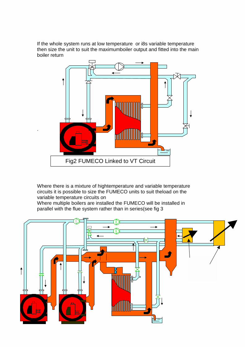
If the whole system runs at low temperature or i8s variable temperaturethen size the unit to suit the maximumboiler output and fitted into the mainboiler return
.
Where there is a mixture of hightemperature and variable temperaturecircuits it is possible to size the FUMECO units to suit theload on thevariable temperature circuits onWhere multiple boilers are installed the FUMECO will be installed inparallel with the flue system rather than in series(see fig 3
Fig2 FUMECO Linked to VT Circuit
VT CircuitCT Circuit

3 System requirementsPipework
Install the FUMECO into the circuit return pipework with a by pass betweenthe connections as shown in figure 3. This will enable the flow to bebalanced on the system.
Ensure that water is always flowing through the FUMECO when any boileris firing otherwise very high water temperatures and boiling may resultCondensate Drain
Run the condensate drain to a suitable gully using plastic pipework . Adeep seal trap should be fitted to prevent the escape of flue gases throughthe pipework. There shou8ld also be an air break to prevent syphoning thetrap. Do not use copper
Flue system
The Flue system downstream of the FUMECO must meet normalcondensing boiler criteria ie• Corrosion resistant smoothwall• Water and gas tight• Free draining• Vertical discharge• Adequately drainedFlue connections to the FUMECO should have a removable section toallow maintenance of the flueways
Electrical connections
All motors supplied with the FUMECO are suitable for 3 phase 400velectrical supplyThe unit should be fitted with a local suitably sized fused isolator .The motor should be interlocked to the boilers to ensure that both units runtogether

4 Installation And Assembly
Fumeco is delivered packed on its side on a pallet with the fan assemblypacked separately
Siting
Decide on a suitable position for the unit avoiding complicatedand resistive flue runs.Remove the unit from the pallet and position on a suitable levelbase adequate to support the weight of the unit when full
The fan housing is fitted with a rope sealing gasket(fig5).Loosen the clamps on top of the main unit (fig 6) andposition the fan housing on top then tighten down theclamps
Fig 5
Sealing gasket

Connect flue system taking into account of maintenance requirements ofthe FUMECOConnect pipework ensuring that the unit is adequately ventedConnect the electrical supply to the fan motor allowing sufficient flexiblewiring to allow removal of the fan housing for maintenance .
6 Maintenance
Occasional maintenance is required but is only a matter of cleaning out anydebris from the lower flue box via the cleanout door (Fig 7). Frequencyonce per year.
Clamp plates
Fig 6
FIG 7Cleanout door
Approximately biannually the top fan housing should be removed .Check the fan unit and motor and maintain as necessary.
Wash down the tubes using a hose and mains water

Baxi Commercial DivisionWood Lane, Erdington, Birmingham B24 9QP Email: [email protected]
Sales:
0845 070 1056Technical:
0845 070 1057 heating specialists
Commercial sales technical & service enquiries
Tel: 0845 070 1055Fax: 0845 070 1059Sales hotline: 0845 070 1056Technical helpline: 0845 070 1057Service hotline: 0845 070 1058e-mail: [email protected]: www.pottertoncommercial.co.uk
Spares
Potterton Commercial spares are available nationwide through the interpart network of approved stockists.Alternatively please contact:-
InterpartBrooks HouseCoventry RoadWarwick CV34 4LL
Tel: 0844 871 1540
Applications & Installations
Our experienced technical support team are available to offeradvice on any aspect of heating system design and boilerinstallation.
Please contact: 0845 070 1057
Commercial service offices
Our service organisation covers the whole of the UK to look afteryour needs for all Potterton Commercial products.
Our service office offers a wide range of specialised servicesincluding:
• Burner commissioning for all fuels• Boiler service contracts• Breakdown and repair services• Burner and boiler replacement• Oil/gas conversions• Water treatment and descaling• Packaged units
All descriptions and illustrations contained within this leaflet havebeen carefully prepared, but we reserve the right to makechanges and improvements in our products which may affectthe accuracy of the information in this leaflet.