functional example simatic safety integrated for factory ... · simatic safety integrated for...
TRANSCRIPT
Functional Example AS-FE-I-013-V12-EN
SIMATIC Safety Integrated for Factory Automation
Practical Application of IEC 62061 Illustrated Using an Application Example
with SIMATIC S7 Distributed Safety
© Siemens AG 2007

Application of IEC 62061 ID Number: 23996473
A&D Safety Integrated AS-FE-013-V12-EN 2/142
Preliminary remark The Functional Examples dealing with “Safety Integrated” are fully functional and tested automation configurations based on A&D standard products for simple, fast and inexpensive implementation of automation tasks in safety engineering. Each of these Functional Examples covers a frequently occurring subtask of a typical customer problem in safety engineering.
Aside from a list of all required software and hardware components and a description of the way they are connected to each other, the Functional Examples include the tested and commented code. This ensures that the functionalities described here can be reset in a short period of time and thus also be used as a basis for individual expansions.
Note The Safety Functional Examples are not binding and do not claim to be complete regarding the circuits shown, equipping and any eventuality. The Safety Functional Examples do not represent customer-specific solutions. They are only intended to provide support for typical applications. You are responsible for ensuring that the described products are correctly used. These Safety Functional Examples do not relieve you of the responsibility of safely and professionally using, installing, operating and servicing equipment. When using these Safety Functional Examples, you recognize that Siemens cannot be made liable for any damage/claims beyond the liability clause described. We reserve the right to make changes to these Safety Functional Examples at any time without prior notice. If there are any deviations between the recommendations provided in these Safety Functional Examples and other Siemens publications – e.g. Catalogs – then the contents of the other documents have priority.
As a quality assurance measure for this document, a review was performed by the Center for Quality Engineering. The independent Center for Quality Engineering accredited according to DIN EN ISO/IEC 17025 confirms that IEC 62061 was correctly applied to the Functional Example and implemented. Further information is available at: www.pruefinstitut.de
© Siemens AG 2007

Application of IEC 62061 ID Number: 23996473
A&D Safety Integrated AS-FE-013-V12-EN 3/142
Cop
yrig
ht ©
Sie
men
s A
G 2
007
All
right
s re
serv
ed
2399
6473
_as_
fe_i
_013
_DO
KU
_v12
_e_3
2.do
c
Table of Contents
Warranty, liability and support .................................................................................... 8
1 Conventions in the Document....................................................................... 9 1.1 Terms and abbreviations from IEC 62061 ........................................................ 9 1.2 References in the document........................................................................... 10 1.3 Orientation in the document............................................................................ 10
2 Contents of the Document........................................................................... 11 2.1 Task of the document ..................................................................................... 11 2.2 Structure of the document .............................................................................. 12
INTRODUCTION .......................................................................................................... 13
3 Introduction................................................................................................... 13 3.1 Safety of machinery ........................................................................................ 13 3.2 Functional safety of a #safety system (SRECS)............................................. 14
4 Overview of IEC 62061 ................................................................................. 16 4.1 Title and status ............................................................................................... 16 4.2 Characteristics ................................................................................................ 16 4.3 Benefit............................................................................................................. 19 4.4 IEC 61508 basic standard .............................................................................. 21
IEC 62061 BASICS ...................................................................................................... 24
5 #Safety-Related Control Function (SRCF).................................................. 24 5.1 #Safety function and SRCF ............................................................................ 24 5.2 Properties of a SRCF...................................................................................... 25
6 #Safety System (SRECS) ............................................................................. 26
7 #Safety Integrity Level (SIL)......................................................................... 29 7.1 Meaning of SIL................................................................................................ 29 7.2 SIL determination............................................................................................ 29 7.3 Achieving the required SIL.............................................................................. 29
8 #Architectural Constraint............................................................................. 31 8.1 Meaning of #SIL claim limit (SILCL) ............................................................... 31 8.2 Requirement view and solution view of the SILCL ......................................... 32 8.3 Factors of influence on the SILCL .................................................................. 33 8.3.1 Hardware fault tolerance (HFT) ...................................................................... 34 8.3.2 #Safe failure fraction (SFF)............................................................................. 36 8.4 Options for determining the SILCL ................................................................. 39 8.5 Finished #subsystem: SILCL determination from the category ...................... 40 8.6 Finished #subsystem: SILCL determination from HFT and SFF .................... 40 8.7 Designed #subsystem: SILCL determination from HFT and SFF................... 41
© Siemens AG 2007

Application of IEC 62061 ID Number: 23996473
A&D Safety Integrated AS-FE-013-V12-EN 4/142
Cop
yrig
ht ©
Sie
men
s A
G 2
007
All
right
s re
serv
ed
2399
6473
_as_
fe_i
_013
_DO
KU
_v12
_e_3
2.do
c
9 #PFHD Value (PFHD) ...................................................................................... 42 9.1 Meaning of PFHD ............................................................................................ 42 9.2 Correlation: SIL and PFHD of a SRCF ............................................................ 43 9.3 Calculating the PFHD of a SRCF .................................................................... 44 9.4 Options for determining the PFHD of a #subsystem ....................................... 45 9.5 Finished #subsystem: PFHD determination from the category ....................... 46 9.6 Designed #subsystem: PFHD calculation........................................................ 47 9.7 Influence on the PFHD of a #subsystem ......................................................... 49 9.7.1 Dangerous failure rate of a #subsystem element (λDe) ................................... 50 9.7.2 CCF factor (β) ................................................................................................. 53 9.7.3 #Diagnostic coverage (DC) and diagnostic test interval (T2).......................... 54 9.7.4 Minimum of lifetime and proof test interval (T1).............................................. 56 9.8 Example: Formula for the PFHD value of basic subsystem architecture D .... 58
10 #Systematic Safety Integrity........................................................................ 61
APPLICATION ............................................................................................................. 63
11 Application Example .................................................................................... 63 11.1 Problem definition of the application example ................................................ 63 11.2 Solution in the application example ................................................................ 64
12 Overview of the Application of IEC 62061 .................................................. 66 12.1 Overview of the steps ..................................................................................... 66 12.2 Activities in parallel to all steps ....................................................................... 68
13 Step 1: Creating #Safety Plan...................................................................... 69 13.1 Objective of the step ....................................................................................... 69 13.2 Procedure ....................................................................................................... 69 13.3 Application ...................................................................................................... 70
14 Step 2: Performing Risk Analysis ............................................................... 72 14.1 Objective of the step ....................................................................................... 72 14.2 Procedure ....................................................................................................... 72 14.3 Application ...................................................................................................... 72
15 Step 3: Performing Risk Assessment......................................................... 73 15.1 Objective of the step ....................................................................................... 73 15.2 Procedure ....................................................................................................... 73 15.2.1 Assessment of the risk of the hazard.............................................................. 73 15.2.2 Determination of the required SIL for the SRCF............................................. 74 15.3 Application ...................................................................................................... 74 15.3.1 Assessment of the risk of the hazard.............................................................. 74 15.3.2 Determination of the required SIL for the SRCF............................................. 77 15.3.3 Form for risk assessment ............................................................................... 78
16 Step 4: Developing SRCF Specification ..................................................... 79 16.1 Objective of the step ....................................................................................... 79
© Siemens AG 2007

Application of IEC 62061 ID Number: 23996473
A&D Safety Integrated AS-FE-013-V12-EN 5/142
Cop
yrig
ht ©
Sie
men
s A
G 2
007
All
right
s re
serv
ed
2399
6473
_as_
fe_i
_013
_DO
KU
_v12
_e_3
2.do
c
16.2 Procedure ....................................................................................................... 79 16.3 Application ...................................................................................................... 80
17 Step 5: Designing SRECS Architecture...................................................... 82 17.1 Objective of the step ....................................................................................... 82 17.2 Procedure ....................................................................................................... 82 17.2.1 Dividing SRCF into #function blocks............................................................... 83 17.2.2 Specifying requirements for #function blocks ................................................. 83 17.2.3 Assigning #function blocks to #subsystems ................................................... 83 17.3 Application ...................................................................................................... 84 17.3.1 Dividing SRCF into #function blocks............................................................... 84 17.3.2 Specifying requirements for #function blocks ................................................. 84 17.3.3 Assigning #function blocks to #subsystems ................................................... 86
18 Step 6: Realizing #Subsystems................................................................... 88 18.1 Structure of the step ....................................................................................... 88 18.2 Objective of the step ....................................................................................... 88 18.3 Procedure ....................................................................................................... 89 18.3.1 Consideration of the #architectural constraint ................................................ 89 18.3.2 Consideration of the PFHD.............................................................................. 89 18.3.3 Consideration of the diagnostics..................................................................... 90 18.3.4 Consideration of the #systematic safety integrity ........................................... 90
19 Step 6 / Application: Overview of the #Subsystems ................................. 91
20 Step 6 / Application: Realizing #Subsystem 1 ........................................... 92 20.1 Design of #subsystem 1 (Detect function block)............................................. 92 20.2 Consideration of the #architectural constraint ................................................ 94 20.3 Consideration of the PFHD.............................................................................. 95 20.3.1 PFHD calculation ............................................................................................. 96 20.3.2 Calculation of the #diagnostic coverage (DC) ................................................ 97 20.4 Consideration of the diagnostics..................................................................... 98 20.5 Consideration of the #systematic safety integrity ........................................... 98 20.6 Summary ........................................................................................................ 98
21 Step 6 / Application: Realizing #Subsystem 2 ........................................... 99 21.1 Design of #subsystem 2 (Evaluate function block) ......................................... 99 21.2 Consideration of the #architectural constraint .............................................. 101 21.3 Consideration of the PFHD............................................................................ 101 21.4 Consideration of the diagnostics................................................................... 102 21.5 Consideration of the #systematic safety integrity ......................................... 102 21.6 Summary ...................................................................................................... 102
22 Step 6 / Application: Realizing #Subsystem 3 ......................................... 103 22.1 Design of #subsystem 3 (React function block)............................................ 103 22.2 Consideration of the #architectural constraint .............................................. 105 22.3 Consideration of the PFHD............................................................................ 106
© Siemens AG 2007

Application of IEC 62061 ID Number: 23996473
A&D Safety Integrated AS-FE-013-V12-EN 6/142
Cop
yrig
ht ©
Sie
men
s A
G 2
007
All
right
s re
serv
ed
2399
6473
_as_
fe_i
_013
_DO
KU
_v12
_e_3
2.do
c
22.3.1 PFHD calculation ........................................................................................... 107 22.3.2 Calculation of the #diagnostic coverage (DC) .............................................. 108 22.4 Consideration of the diagnostics................................................................... 109 22.5 Consideration of the #systematic safety integrity ......................................... 109 22.6 Summary ...................................................................................................... 109
23 Step 7: Determining SIL Achieved by SRECS.......................................... 110 23.1 Objective of the step ..................................................................................... 110 23.2 Procedure ..................................................................................................... 110 23.2.1 Determination of the minimum SILCL of all #subsystems of the SRCF........ 111 23.2.2 Determination of the PFHD of the SRCF....................................................... 111 23.2.3 Derivation of the SIL which is achieved with the SRECS ............................. 111 23.2.4 Measures to achieve the required SIL .......................................................... 112 23.3 Application .................................................................................................... 112 23.3.1 Determination of the minimum SILCL of all #subsystems of the SRCF........ 112 23.3.2 Determination of the PFHD of the SRCF....................................................... 113 23.3.3 Derivation of the SIL which is achieved with the SRECS ............................. 113
24 Steps 8 to 12: Implementing SRECS......................................................... 114
25 Step 13: Generating Information for Use.................................................. 115 25.1 Objective of the step ..................................................................................... 115 25.2 Procedure ..................................................................................................... 115
26 Step 14: Performing Validation ................................................................. 116 26.1 Objective of the step ..................................................................................... 116 26.2 Procedure ..................................................................................................... 116
APPENDIX ................................................................................................................. 117
27 Background Information ............................................................................ 117 27.1 Risk analysis and risk assessment ............................................................... 117 27.2 CCF factor (β) ............................................................................................... 119 27.3 Failure modes of electrical / electronic components ..................................... 120 27.4 SIMATIC S7 Distributed Safety: Safety-related data .................................... 121 27.5 SIRIUS: Safety-related data ......................................................................... 122 27.6 Fault, diagnostics and failure (according to IEC 62061) ............................... 123 27.6.1 Fault.............................................................................................................. 123 27.6.2 Diagnostics ................................................................................................... 125 27.6.3 Failure........................................................................................................... 126 27.6.4 Examples: Overview ..................................................................................... 128 27.6.5 Example 1: Zero fault tolerance without diagnostics .................................... 129 27.6.6 Example 2: Zero fault tolerance with diagnostics ......................................... 130 27.6.7 Example 3: Single fault tolerance without diagnostics.................................. 131 27.6.8 Example 4: Single fault tolerance with diagnostics....................................... 133 27.7 Category according to EN 954-1: 1996 ........................................................ 135
© Siemens AG 2007

Application of IEC 62061 ID Number: 23996473
A&D Safety Integrated AS-FE-013-V12-EN 7/142
Cop
yrig
ht ©
Sie
men
s A
G 2
007
All
right
s re
serv
ed
2399
6473
_as_
fe_i
_013
_DO
KU
_v12
_e_3
2.do
c
28 Glossary ...................................................................................................... 136 28.1 Terms from IEC 62061 ................................................................................. 136 28.2 Abbreviations from IEC 62061...................................................................... 139 28.3 General abbreviations................................................................................... 140
29 Information Directory ................................................................................. 141
30 History of the Document ............................................................................ 142
© Siemens AG 2007

Application of IEC 62061 ID Number: 23996473
A&D Safety Integrated AS-FE-013-V12-EN 8/142
Cop
yrig
ht ©
Sie
men
s A
G 2
007
All
right
s re
serv
ed
2399
6473
_as_
fe_i
_013
_DO
KU
_v12
_e_3
2.do
c
Warranty, liability and support
We do not accept any liability for the information contained in this document.
Any claims against us – based on whatever legal reason – resulting from the use of the examples, information, programs, engineering and performance data etc., described in this Safety Functional Example shall be excluded. Such an exclusion shall not apply in the case of mandatory liability, e.g. under the German Product Liability Act (“Produkthaftungsgesetz”), in case of intent, gross negligence, or injury of life, body or health, guarantee for the quality of a product, fraudulent concealment of a deficiency or breach of a condition which goes to the root of the contract (“wesentliche Vertragspflichten”). However, claims arising from a breach of a condition which goes to the root of the contract shall be limited to the foreseeable damage which is intrinsic to the contract, unless caused by intent or gross negligence or based on mandatory liability for injury of life, body or health. The above provisions does not imply a change in the burden of proof to your detriment.
Copyright© 2007 Siemens A&D. It is not permissible to transfer or copy these Safety Functional Examples or excerpts of them without first having prior authorization from Siemens A&D in writing.
For questions about this document please use the following e-mail-address:
© Siemens AG 2007

INTRODUCTIONConventions in the Document
Application of IEC 62061 ID Number: 23996473
A&D Safety Integrated AS-FE-013-V12-EN 9/142
Cop
yrig
ht ©
Sie
men
s A
G 2
007
All
right
s re
serv
ed
2399
6473
_as_
fe_i
_013
_DO
KU
_v12
_e_3
2.do
c
1 Conventions in the Document
The chapter describes which conventions apply in the document. To use the document, it is important to know these conventions.
1.1 Terms and abbreviations from IEC 62061
Terms from IEC 62061 Numerous terms from IEC 62061 are used in the document. These terms have defined meanings and are uniquely defined in IEC 62061.
In the document, key terms from IEC 62061 are marked with the “#” character and defined in the glossary (chapter 28.1). The definition in the glossary is identical to the definition in IEC 62061.
Example: #Safety-related control function (SRCF)
If an abbreviation exists for a term from IEC 62061, this abbreviation is added to the term (in the above example: SRCF). In the document, abbreviations are also used by themselves if it improves readability.
If you come across a term prefixed by “#” when reading the document, you see that
• the term is from IEC 62061.
• the definition of the term is listed in the glossary (chapter 28.1).
Abbreviated notation of terms The notation of some terms from IEC 62061 is very long. To improve the readability of this document, an abbreviated notation is used for some terms. Table 1-1
Notation in IEC 62061 Abbreviated notation in the document
Safety-related electrical, electronic and programmable electronic control system (SRECS)
#Safety system (SRECS)
Probability of dangerous failure per hour (PFHD)
#PFHD value (PFHD)
Functional safety plan #Safety plan
© Siemens AG 2007

INTRODUCTIONConventions in the Document
Application of IEC 62061 ID Number: 23996473
A&D Safety Integrated AS-FE-013-V12-EN 10/142
Cop
yrig
ht ©
Sie
men
s A
G 2
007
All
right
s re
serv
ed
2399
6473
_as_
fe_i
_013
_DO
KU
_v12
_e_3
2.do
c
Abbreviations from IEC 62061 Abbreviations from IEC 62061 are used in the document.
Examples: SRCF, SRECS, SIL, SILCL, PFHD
For an overview of the abbreviations, please refer to the glossary (chapter 28.2).
General abbreviations Generally valid abbreviations are also listed in the glossary ( 28.3).
Examples: PLC, F-PLC
1.2 References in the document
References to documents and links to the internet are marked with “(/x/)”. For an overview of all references and links, please refer to chapter 29.
1.3 Orientation in the document
The header of the document is useful for the orientation in the document. This is illustrated by the figure below with a screen shot of the header.
Figure 1-1
The first line of the header indicates the respective part of the document.
The second line of the header indicates the corresponding chapter.
© Siemens AG 2007

INTRODUCTIONContents of the Document
Application of IEC 62061 ID Number: 23996473
A&D Safety Integrated AS-FE-013-V12-EN 11/142
Cop
yrig
ht ©
Sie
men
s A
G 2
007
All
right
s re
serv
ed
2399
6473
_as_
fe_i
_013
_DO
KU
_v12
_e_3
2.do
c
2 Contents of the Document
The chapter describes task and structure of the document.
2.1 Task of the document
Reason for this document Nowadays, fail-safe programmable logic controllers (F-PLC) simultaneously perform standard and #safety functions on a machine.
Example: Monitoring a safety door
Machines must be “safe”. Among other things, this means that the operator has to be protected against hazards caused by operational faults. An operational fault has, for example, occurred if a #safety function has not been performed correctly.
Example: Failure of the monitoring of a safety door.
IEC 62061 describes requirements that have to be met to ensure functional safety. IEC 62061 is, for example, applied when #safety functions are performed on a machine by an F-PLC.
Objective of the document This document uses a specific application example to illustrate the basic application of IEC 62061.
The following components are used in the application example:
• Fail-safe programmable logic controller (F-PLC): SIMATIC S7 Distributed Safety
• Sensors and actuators: SIRIUS
The objective of the document is to illustrate the most important aspects of IEC 62061. Not all aspects of the IEC 62061 standard are considered in the document. The application example described in the document is used to illustrate the most important correlations and is thus not executed in all details. The specific application of IEC 62061 requires that the original standard is used to ensure that all aspects are considered.
Benefit of the document The document provides the reader with answers to the following questions:
• What are the fundamental principles of IEC 62061?
• How is IEC 62061 basically applied (“main thread”)?
© Siemens AG 2007

INTRODUCTIONContents of the Document
Application of IEC 62061 ID Number: 23996473
A&D Safety Integrated AS-FE-013-V12-EN 12/142
Cop
yrig
ht ©
Sie
men
s A
G 2
007
All
right
s re
serv
ed
2399
6473
_as_
fe_i
_013
_DO
KU
_v12
_e_3
2.do
c
Potential readers of the document The document is aimed at persons who plan, realize or assess #safety functions on machines. These #safety functions are performed by a fail-safe programmable logic controller (F-PLC).
This document does not address IEC 62061 experts, but users who want to familiarize with the IEC 62061 standard.
2.2 Structure of the document
The document is divided into several parts. The structure is explained in the following table. Table 2-1
Part Chapter Contents
INTRODUCTION 3 to 4 The first part of the document provides an introduction to the subject and a brief overview of IEC 62061.
IEC 62061 BASICS
5 to 10 The second part of the document explains the most important terms and correlations of IEC 62061.
APPLICATION 11 to 26 The third part of the document uses an application example to show step-by-step how IEC 62061 is basically applied.
APPENDIX 27 to 29 The fourth part of the document provides in-depth information, a glossary and an information directory.
© Siemens AG 2007

INTRODUCTIONIntroduction
Application of IEC 62061 ID Number: 23996473
A&D Safety Integrated AS-FE-013-V12-EN 13/142
Cop
yrig
ht ©
Sie
men
s A
G 2
007
All
right
s re
serv
ed
2399
6473
_as_
fe_i
_013
_DO
KU
_v12
_e_3
2.do
c
INTRODUCTION
3 Introduction
In the IEC 62061 environment, the following terms play an important role:
• Safety of machinery
• #Safety function, #safety system (SRECS)
• Functional safety of a #safety system (SRECS)
This chapter provides a brief explanation of these terms and shows where IEC 62061 is applied.
3.1 Safety of machinery
Machinery Machinery means an assembly of linked parts or components, at least one of which moves, with actuators, control and power circuits.
Machinery also means an assembly of machines in the sense of a linked system designed to achieve the same end.
Safety components (e.g. position switches) for machines are also part of the machines. Safety components are required to realize #safety functions (e.g. monitoring a safety door).
A failure or an operational fault of a #safety function endangers:
• The health of persons in the range of action of the machine
• The machine
Safety of a machine A machine is “safe” if no hazards arise from it.
Safety requires protection against the following hazards:
• Electric shock
• Heat and fire
• Hazardous radiation and emission
• Mechanical hazards
• Hazardous materials
• Operational faults
© Siemens AG 2007

INTRODUCTIONIntroduction
Application of IEC 62061 ID Number: 23996473
A&D Safety Integrated AS-FE-013-V12-EN 14/142
Cop
yrig
ht ©
Sie
men
s A
G 2
007
All
right
s re
serv
ed
2399
6473
_as_
fe_i
_013
_DO
KU
_v12
_e_3
2.do
c
3.2 Functional safety of a #safety system (SRECS)
#Safety system (SRECS) According to IEC 62061, a #safety system (SRECS) has the following properties:
• A #safety system (SRECS) is an electrical, electronic and programmable electronic control system.
• A #safety system (SRECS) performs #safety functions
In manufacturing automation (e.g. machinery technology, conveyor systems), fail-safe programmable logic controllers (F-PLC) are increasingly used in #safety systems (SRECS).
Example of a #safety system (SRECS):
A #safety system (SRECS) comprises all components required to perform #safety functions on a machine:
• Sensors
• F-PLC
• Actuators
An example of an F-PLC in a #safety system (SRECS) is “SIMATIC S7 Distributed Safety”, consisting of:
• Hardware: Fail-safe S7-CPUs, fail-safe input modules and fail-safe output modules
• Software: “S7 Distributed Safety”, for programming and configuring
Example of a #safety function:
On a machine a protective cover protects the operator against a rotating blade. Figure 3-1
The #safety function is then, for example, defined as follows:
• “The blade must not rotate when the protective cover is open”.
© Siemens AG 2007
INTRODUCTIONIntroduction
Application of IEC 62061 ID Number: 23996473
A&D Safety Integrated AS-FE-013-V12-EN 15/142
Cop
yrig
ht ©
Sie
men
s A
G 2
007
All
right
s re
serv
ed
2399
6473
_as_
fe_i
_013
_DO
KU
_v12
_e_3
2.do
c
Functional safety of a #safety system (SRECS) Functional safety of a #safety system (SRECS) is ensured when the two following requirements are met:
• All #safety functions are performed correctly.
• When a fault occurs in the #safety system (SRECS), no dangerous state arises on the machine.
A #safety system (SRECS) thus has to perform the #safety functions correctly and react correctly when faults occur.
The reaction to a fault does not necessarily have to cause a stop of the machine. A safe state can, for example, also be achieved when hazardous motions on the machine are decelerated.
Examples of faults in a #safety system (SRECS):
• Break of the actuator of a position switch
• Contacts of a contactor do not open
The IEC 62061 standard The internationally valid IEC 62061 standard describes the protection against operational faults of a #safety system (SRECS).
IEC 62061 describes which specific requirements have to be met to ensure the functional safety of a SRECS.
© Siemens AG 2007

INTRODUCTIONOverview of IEC 62061
Application of IEC 62061 ID Number: 23996473
A&D Safety Integrated AS-FE-013-V12-EN 16/142
Cop
yrig
ht ©
Sie
men
s A
G 2
007
All
right
s re
serv
ed
2399
6473
_as_
fe_i
_013
_DO
KU
_v12
_e_3
2.do
c
4 Overview of IEC 62061
This chapter provides a brief overview of IEC 62061.
4.1 Title and status
Title of IEC 62061 Safety of machinery: Functional safety of safety-related electrical, electronic and programmable electronic control systems.
Title of the German version of IEC 62061 Sicherheit von Maschinen: Funktionale Sicherheit sicherheitsbezogener elektrischer, elektronischer und programmierbarer elektronischer Steuerungssysteme.
Status of IEC 62061 Table 4-1
Status of IEC 62061 Date Name
International standard 2005 IEC 62061 European standard harmonized under the machinery directive
2005 EN 62061
4.2 Characteristics
IEC 62061 will be briefly described below.
Field of application of IEC 62061 The internationally valid IEC 62061 standard applies to machines which use a #safety system (SRECS) to perform #safety functions.
Users of IEC 62061 The users of IEC 62061 plan, realize or review #safety functions on machines which are performed by a #safety system (SRECS).
The users can be divided into:
• Machine manufacturers: Have requirements for #safety functions.
• Control integrators: Realize #safety functions with a SRECS.
• Safety experts: Inspect the safety of machinery.
© Siemens AG 2007
INTRODUCTIONOverview of IEC 62061
Application of IEC 62061 ID Number: 23996473
A&D Safety Integrated AS-FE-013-V12-EN 17/142
Cop
yrig
ht ©
Sie
men
s A
G 2
007
All
right
s re
serv
ed
2399
6473
_as_
fe_i
_013
_DO
KU
_v12
_e_3
2.do
c
Examples of safety experts:
• German Technical Inspectorate (TÜV)
• Center for Quality Engineering (see page 2, “note”)
• BG-Institute for Occupational Safety and Health (BGIA)
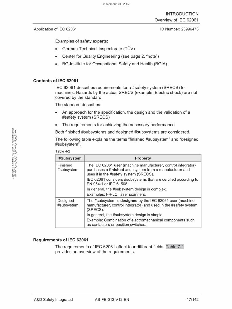
Contents of IEC 62061 IEC 62061 describes requirements for a #safety system (SRECS) for machines. Hazards by the actual SRECS (example: Electric shock) are not covered by the standard.
The standard describes:
• An approach for the specification, the design and the validation of a #safety system (SRECS)
• The requirements for achieving the necessary performance
Both finished #subsystems and designed #subsystems are considered.
The following table explains the terms “finished #subsystem” and “designed #subsystem”. Table 4-2
#Subsystem Property
Finished #subsystem
The IEC 62061 user (machine manufacturer, control integrator) purchases a finished #subsystem from a manufacturer and uses it in the #safety system (SRECS). IEC 62061 considers #subsystems that are certified according to EN 954-1 or IEC 61508. In general, the #subsystem design is complex. Examples: F-PLC, laser scanners.
Designed #subsystem
The #subsystem is designed by the IEC 62061 user (machine manufacturer, control integrator) and used in the #safety system (SRECS). In general, the #subsystem design is simple. Example: Combination of electromechanical components such as contactors or position switches.
Requirements of IEC 62061 The requirements of IEC 62061 affect four different fields. Table 7-1 provides an overview of the requirements.
© Siemens AG 2007

INTRODUCTIONOverview of IEC 62061
Application of IEC 62061 ID Number: 23996473
A&D Safety Integrated AS-FE-013-V12-EN 18/142
Cop
yrig
ht ©
Sie
men
s A
G 2
007
All
right
s re
serv
ed
2399
6473
_as_
fe_i
_013
_DO
KU
_v12
_e_3
2.do
c
Objectives of IEC 62061 If the IEC 62061 requirements are met by corresponding measures, the functional safety of the #safety system (SRECS) is ensured.
This means that the risk of hazards caused by operational faults of the SRECS is minimized.
When realizing a SRECS, the objective is to keep the probability of both “systematic dangerous faults” and “random dangerous faults” adequately low.
Properties of IEC 62061 The standard describes a systematic procedure for the design and the integration of a #safety system (SRECS) for a machine. The standard deals with the two fields:
• Organization / management (example: The standard requires the development of specifications)
• Engineering (example: The standard includes hardware requirements)
The standard is specific, it quantifies safety requirements:
• #Safety integrity level (SIL) level for specifying the #safety integrity requirements of a #safety-related control function (SRCF)
• #PFHD value (PFHD) probability of dangerous failure per hour
The standard considers the entire sequence:
• From the potential hazard on the machine
• and the #safety function required for risk reduction
• to the required #safety integrity level (SIL) of the #safety function.
The standard considers the complete #safety function:
• From the acquisition of information (sensor)
• and the evaluation of information (F-PLC)
• to the response with actions (actuator)
© Siemens AG 2007

INTRODUCTIONOverview of IEC 62061
Application of IEC 62061 ID Number: 23996473
A&D Safety Integrated AS-FE-013-V12-EN 19/142
Cop
yrig
ht ©
Sie
men
s A
G 2
007
All
right
s re
serv
ed
2399
6473
_as_
fe_i
_013
_DO
KU
_v12
_e_3
2.do
c
The standard considers the complete life cycle of a machine:
• Concept, realization, commissioning, operation, maintenance
The standard is an application-specific standard:
• IEC 62061 (sector standard) is derived from the application-independent IEC 61508 standard (basic standard).
• IEC 62061 is thus based on the principles and the terminology of IEC 61508.
4.3 Benefit
General benefit of IEC 62061 The existence and the application of IEC 62061 provide the following benefits:
• The IEC 62061 standard is internationally valid. This means:
– The export of machines is facilitated.
– International standards in safety engineering are developed, safety engineering becomes internationally comparable.
• IEC 62061 is an aid for users and testing agencies dealing with “functional safety of #safety systems (SRECS)”.
• With the aid of the standard, the user reaches his/her target more quickly:
– From the safety requirement
– to the safety solution conforming to standards
• The user can use finished #subsystems that are certified according to EN 954-1 or IEC 61508 (table 4-2).
• The standard facilitates the assessment of an F-PLC (SIMATIC S7 Distributed Safety) with regard to the functional safety. Using an F-PLC, intelligent safety solutions can be realized which minimize downtimes and increase productivity.
• A #safety system (SRECS) is considered to be functionally safe when the requirements of the standard are met.
© Siemens AG 2007

INTRODUCTIONOverview of IEC 62061
Application of IEC 62061 ID Number: 23996473
A&D Safety Integrated AS-FE-013-V12-EN 20/142
Cop
yrig
ht ©
Sie
men
s A
G 2
007
All
right
s re
serv
ed
2399
6473
_as_
fe_i
_013
_DO
KU
_v12
_e_3
2.do
c
Additional benefit of IEC 62061 in the European Union (EU) In the EU, the “presumption of conformity” applies to EN 62061 since EN 62061 is a “harmonized standard” (/2/).
Presumption of conformity
By complying with a harmonized standard, an “automatic presumption of conformity” ensues for the compliance with the corresponding directive.
The user of a harmonized standard can trust in having complied with the safety objectives of the corresponding directive.
For EN 62061 this specifically means:
• By applying EN 62061, the user may assume that he/she has complied with the safety objectives of the machinery directive.
Harmonized standard
Harmonized standards are published in the Official Journal of the European Union (/3/) and applied to national standards without modifications.
They are, among other things, used to comply with the protection objectives listed in the machinery directive.
Machinery directive
Machines which are put into circulation or operated in the EU have to comply with the machinery directive requirements.
The machinery directive includes basic safety requirements for machines and for replaceable equipment and safety components.
This also affects machines which are delivered to the EU from countries which are not part of the EU.
© Siemens AG 2007

INTRODUCTIONOverview of IEC 62061
Application of IEC 62061 ID Number: 23996473
A&D Safety Integrated AS-FE-013-V12-EN 21/142
Cop
yrig
ht ©
Sie
men
s A
G 2
007
All
right
s re
serv
ed
2399
6473
_as_
fe_i
_013
_DO
KU
_v12
_e_3
2.do
c
4.4 IEC 61508 basic standard
Title of IEC 61508 Functional safety of electrical/electronic/programmable electronic safety-related systems.
Title of the German version of IEC 61508 Funktionale Sicherheit sicherheitsbezogener elektrischer/elektronischer/programmierbarer elektronischer Systeme.
Basic standard and sector standard IEC 61508 deals with the functional safety of safety-related E/E/PES. IEC 61508 is independent of the application of the safety-related E/E/PES. For this reason, IEC 61508 is referred to as basic standard.
Standards are derived from the IEC 61508 basic standard, which are tailored to specific applications. These derived standards are referred to as sector standards.
Examples of sector standards of the IEC 61508 basic standard:
• IEC 61511: The standard is applied in the process industry.
• IEC 62061: The standard is applied in machines.
Advantages of a sector standard The existence of a sector standard for machines has the following advantages for the user:
• The sector standard (IEC 62061) is a subset of the basic standard (IEC 62508) and thus less comprehensive and easier to apply.
• The sector standard considers special conditions of machine building. This enables to simplify complex basic standard requirements in the sector standard.
• Machine building terminology is used in the sector standard. This increases the comprehension for the user.
• The sector standard enables the user to achieve functional safety without knowing the basic standard.
• By applying the sector standard, the basic standard requirements are simultaneously met.
© Siemens AG 2007

INTRODUCTIONOverview of IEC 62061
Application of IEC 62061 ID Number: 23996473
A&D Safety Integrated AS-FE-013-V12-EN 22/142
Cop
yrig
ht ©
Sie
men
s A
G 2
007
All
right
s re
serv
ed
2399
6473
_as_
fe_i
_013
_DO
KU
_v12
_e_3
2.do
c
Comparison of IEC 61508 and IEC 62061 The table below illustrates the differences. Table 4-3
IEC 61508 basic standard IEC 62061 sector standard
Title Functional safety of electrical/electronic/ programmable electronic safety-related systems.
Safety of machinery: Functional safety of safety-related electrical, electronic and programmable electronic control systems.
Terminology, principles
Identical for both standards
All applications in which an E/E/PES is used for safety tasks.
Machines in which a SRECS is used to perform #safety functions.
Field of application
Examples: • Turbine control systems • Medical equipment • Fairground rides
Example: • Monitoring and securing
protection zones on a machine
Manufacturers of safety engineering: • Safety-related E/E/PES
(example: F-PLC). • Components of a
safety-related E/E/PES (example: Laser scanners)
Users
Developers of sector standards
Machine manufacturers Control integrators Safety experts
International standard since
1998 2005
© Siemens AG 2007

INTRODUCTIONOverview of IEC 62061
Application of IEC 62061 ID Number: 23996473
A&D Safety Integrated AS-FE-013-V12-EN 23/142
Cop
yrig
ht ©
Sie
men
s A
G 2
007
All
right
s re
serv
ed
2399
6473
_as_
fe_i
_013
_DO
KU
_v12
_e_3
2.do
c
SIMATIC S7 Distributed Safety The “SIMATIC S7 Distributed Safety” F-PLC is certified as a safety-related programmable system according to IEC 61508. The system is thus suitable for use in fail-safe applications.
The certification provides the “SIMATIC S7 Distributed Safety” user with the following advantages:
• When observing the “SIMATIC S7 Distributed Safety” configuration guidelines, IEC 62061 is automatically complied with.
• If an acceptance of the machine is required according to IEC 62061, the acceptance jurisdictions only have to evaluate the correct use and the compliance with the “SIMATIC S7 Distributed Safety” configuration guidelines.
© Siemens AG 2007

IEC 62061 BASICS#Safety-Related Control Function (SRCF)
Application of IEC 62061 ID Number: 23996473
A&D Safety Integrated AS-FE-013-V12-EN 24/142
Cop
yrig
ht ©
Sie
men
s A
G 2
007
All
right
s re
serv
ed
2399
6473
_as_
fe_i
_013
_DO
KU
_v12
_e_3
2.do
c
IEC 62061 BASICS
5 #Safety-Related Control Function (SRCF)
5.1 #Safety function and SRCF
Delimitation #safety function and SRCF To simplify matters, so far the term #safety functions has been used exclusively in the document. However, the IEC 62061 standard considers #safety-related control functions (SRCFs).
The correlation is described below:
• The necessity to minimize the risk with the aid of #safety functions results from the risk analysis for the machine.
• To realize #safety functions, a #safety system (SRECS) can be used on the machine.
• The #safety system (SRECS) then performs #safety-related control functions (SRCFs) to realize the #safety functions.
Example to illustrate the difference:
The #safety function for the machine is to be:
• “The blade must not rotate when the protective cover is open”.
To realize the #safety function, a #safety system (SRECS) is used. The SRECS consists of sensors, actuators and a fail-safe programmable logic controller (F-PLC).
The #safety system (SRECS) performs a #safety-related control function (SRCF) to realize this #safety function. The designation of the SRCF is then, for example, defined as follows:
• “Stop of the rotating blade”
The #safety-related control function (SRCF) consists of:
• Detecting the position of the protective cover via sensor
• Evaluating the information in the F-PLC
• Reacting by switching off the motor via actuator
© Siemens AG 2007

IEC 62061 BASICS#Safety-Related Control Function (SRCF)
Application of IEC 62061 ID Number: 23996473
A&D Safety Integrated AS-FE-013-V12-EN 25/142
Cop
yrig
ht ©
Sie
men
s A
G 2
007
All
right
s re
serv
ed
2399
6473
_as_
fe_i
_013
_DO
KU
_v12
_e_3
2.do
c
5.2 Properties of a SRCF
Task of a SRCF #Safety-related control functions (SRCFs) are performed by a #safety system (SRECS). The task of a SRCF is to prevent dangerous states on a machine.
A SRCF has to meet requirements with regard to:
• Functionality and
• #safety integrity.
Functionality of a SRCF The required functionality of a #safety-related control function (SRCF) is derived from the risk analysis (chapter 14).
In general, a SRCF consists of the following #function blocks:
• Acquiring information
• Evaluating information
• Responding with actions
The figure shows a SRCF divided into its #function blocks: Figure 5-1
#Safety integrity of a SRCF #Safety-related control functions (SRCFs) must operate reliably. The higher the risk of a hazard arising from an operational fault of a SRCF, the higher the reliability requirements of this SRCF. This reliability is referred to as #safety integrity.
The #safety integrity level (SIL) (chapter 7) is the measure for the #safety integrity of a SRCF.
© Siemens AG 2007

IEC 62061 BASICS#Safety System (SRECS)
Application of IEC 62061 ID Number: 23996473
A&D Safety Integrated AS-FE-013-V12-EN 26/142
Cop
yrig
ht ©
Sie
men
s A
G 2
007
All
right
s re
serv
ed
2399
6473
_as_
fe_i
_013
_DO
KU
_v12
_e_3
2.do
c
6 #Safety System (SRECS)
Properties of a SRECS A #safety system (SRECS) is an electrical control system on a machine whose failure may cause a reduction or loss of safety. The failure of a SRECS may cause a dangerous state on the machine.
A SRECS comprises all electrical parts required for performing #safety-related control functions (SRCFs):
• Sensors, F-PLC, actuators
• Power and control circuits
Task of a SRECS A #safety system (SRECS) performs #safety-related control functions (SRCFs). The SRECS has to meet the following requirements:
• Correct performance of the SRCFs
• Reaction to faults in the SRECS
If faults occur in the SRECS which no longer allow a correct performance of a SRCF (loss of the SRCF), the SRECS has to behave in such a way that no dangerous state occurs on the machine. In the event of a fault, the SRECS must thus behave in such a way that the #safety function is still performed.
Architecture of a SRECS A #safety system (SRECS) has the following properties:
• It performs #safety-related control functions (SRCFs).
• It consists of #subsystems.
A #subsystem has the following properties:
• A #subsystem executes a #function block of a SRCF.
• The failure of a #subsystem causes a loss of the SRCFs that use this #subsystem.
• A #subsystem consists of one or several #subsystem elements.
Below two examples are used to illustrate the architecture of a #safety system (SRECS):
© Siemens AG 2007
IEC 62061 BASICS#Safety System (SRECS)
Application of IEC 62061 ID Number: 23996473
A&D Safety Integrated AS-FE-013-V12-EN 27/142
Cop
yrig
ht ©
Sie
men
s A
G 2
007
All
right
s re
serv
ed
2399
6473
_as_
fe_i
_013
_DO
KU
_v12
_e_3
2.do
c
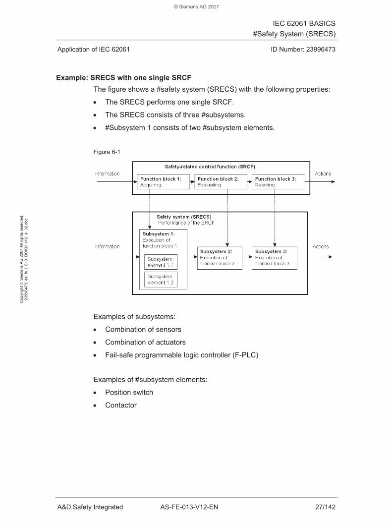
Example: SRECS with one single SRCF The figure shows a #safety system (SRECS) with the following properties:
• The SRECS performs one single SRCF.
• The SRECS consists of three #subsystems.
• #Subsystem 1 consists of two #subsystem elements.
Figure 6-1
Examples of subsystems:
• Combination of sensors
• Combination of actuators
• Fail-safe programmable logic controller (F-PLC)
Examples of #subsystem elements:
• Position switch
• Contactor
© Siemens AG 2007

IEC 62061 BASICS#Safety System (SRECS)
Application of IEC 62061 ID Number: 23996473
A&D Safety Integrated AS-FE-013-V12-EN 28/142
Cop
yrig
ht ©
Sie
men
s A
G 2
007
All
right
s re
serv
ed
2399
6473
_as_
fe_i
_013
_DO
KU
_v12
_e_3
2.do
c
Example: SRECS with two SRCFs The figure shows a #safety system (SRECS) with the following properties:
• The SRECS performs two SRCFs.
• The SRECS consists of five #subsystems.
• #Subsystem 3 is used by both SRCFs.
Figure 6-2
© Siemens AG 2007

IEC 62061 BASICS#Safety Integrity Level (SIL)
Application of IEC 62061 ID Number: 23996473
A&D Safety Integrated AS-FE-013-V12-EN 29/142
Cop
yrig
ht ©
Sie
men
s A
G 2
007
All
right
s re
serv
ed
2399
6473
_as_
fe_i
_013
_DO
KU
_v12
_e_3
2.do
c
7 #Safety Integrity Level (SIL)
7.1 Meaning of SIL
The #safety integrity level (SIL) is a measure for specifying the requirements for the #safety integrity of a #safety-related control function (SRCF). In IEC 62061, three discrete levels are used as a measure for the SIL:
• SIL 1, SIL 2 and SIL 3
The higher the requirements for the #safety integrity of a SRCF, the higher the SIL required for the SRCF. A #safety integrity level (SIL) of SIL 3 has the highest requirements for the reliability of the SRCF. This level has the highest probability that the #safety system (SRECS) performs the correct function when it is required.
The SRCF must comply with the SIL requirements and consequently also the #safety system (SRECS) and its #subsystems have to meet these requirements.
7.2 SIL determination
First, the risk analysis (chapter 14) determines whether #safety-related control functions (SRCFs) for risk reduction are required on the machine.
The necessary #safety integrity level (SIL) for each SRCF is then determined in the risk assessment (chapter 15). The higher the risk reduction has to be, the more reliable the performance of the SRCF must be, the higher the required SIL for the SRCF.
7.3 Achieving the required SIL
To achieve the required #safety integrity level (SIL) for a #safety-related control function (SRCF), the #safety system (SRECS) and its #subsystems have to meet the requirements described in IEC 62061.
In general, a higher SRCF reliability (higher SIL) also requires more technical extra work when realizing the #safety system (SRECS).
The table below provides an overview of the IEC 62061 requirements for a SRECS and its #subsystems.
© Siemens AG 2007

IEC 62061 BASICS#Safety Integrity Level (SIL)
Application of IEC 62061 ID Number: 23996473
A&D Safety Integrated AS-FE-013-V12-EN 30/142
Cop
yrig
ht ©
Sie
men
s A
G 2
007
All
right
s re
serv
ed
2399
6473
_as_
fe_i
_013
_DO
KU
_v12
_e_3
2.do
c
Table 7-1
IEC 62061 requirements Grading according
to SIL?
#Architectural constraint: Properties of the structure of the #safety system (SRECS)
Clear Requirements for the “safety integrity of the hardware”, consisting of: #PFHD value (PFHD):
Probability of dangerous failure per hour
Clear
Avoidance of systematic faults Requirements for the #systematic safety integrity, consisting of:
Control of systematic faults
Slight
Requirements for the #safety system (SRECS) behavior when detecting a dangerous fault: Fault detection (diagnostics) and fault reaction
None
Requirements for the design and development of safety-related application software.
None
The following table provides a brief explanation of the IEC 62061 core requirements. Details are available in the mentioned chapters. Table 7-2
Requirement Explanation Details
#Architectural constraint
The structure (architecture) of the #subsystems must be suitable for the required SIL. The structure of a #subsystem is described by the #SIL claim limit (SILCL). Examples of different structures: • #Subsystem with/without redundancy
or with/without diagnostics.
Chapter 8
#PFHD value (PFHD) The probability of a dangerous SRECS failure per hour when performing the SRCF must not exceed a specific limit value. This limit value is defined by the required SIL.
Chapter 9
#Systematic safety integrity
Measures for the avoidance and control of systematic faults have to be taken. Examples of systematic faults: • Errors in the specification of the SRCF • Errors when designing hardware or
application software
Chapter 10
© Siemens AG 2007

IEC 62061 BASICS#Architectural Constraint
Application of IEC 62061 ID Number: 23996473
A&D Safety Integrated AS-FE-013-V12-EN 31/142
Cop
yrig
ht ©
Sie
men
s A
G 2
007
All
right
s re
serv
ed
2399
6473
_as_
fe_i
_013
_DO
KU
_v12
_e_3
2.do
c
8 #Architectural Constraint
8.1 Meaning of #SIL claim limit (SILCL)
Starting point of the #SIL claim limit (SIL) considerations:
A #safety-related control function (SRCF) must comply with a required #safety integrity level (SIL):
• A SRCF is performed by a #safety system (SRECS).
• The SRECS must be suitable for this SIL.
• The SRECS #subsystems must be suitable for this SIL.
Now the #SIL claim limit (SILCL) comes into play:
• The SILCL is a property of a #subsystem.
• The SILCL indicates the maximum SIL for which a #subsystem is suitable.
If a #subsystem has a specific #SIL claim limit (SILCL), this means:
• The #subsystem has a defined #systematic safety integrity.
• The #subsystem has a defined #architectural constraint.
The correlations are explained in the following table: Table 8-1
Defined with the SILCL:
Meaning Grading according
to SIL?
Details
#Systematic safety integrity
Avoidance and control of systematic faults.
Slight Chapter 10
#Architectural constraint
#Subsystem structure (architecture): • Hardware fault tolerance (HFT) • #Safe failure fraction (SFF)
Clear Chapter 8.4
Example:
The statement “the #subsystem has SILCL 2” describes the properties:
• The #subsystem meets all IEC 62061 requirements for #systematic safety integrity.
• The structure of the #subsystem is maximally suitable for SIL 2.
© Siemens AG 2007
IEC 62061 BASICS#Architectural Constraint
Application of IEC 62061 ID Number: 23996473
A&D Safety Integrated AS-FE-013-V12-EN 32/142
Cop
yrig
ht ©
Sie
men
s A
G 2
007
All
right
s re
serv
ed
2399
6473
_as_
fe_i
_013
_DO
KU
_v12
_e_3
2.do
c
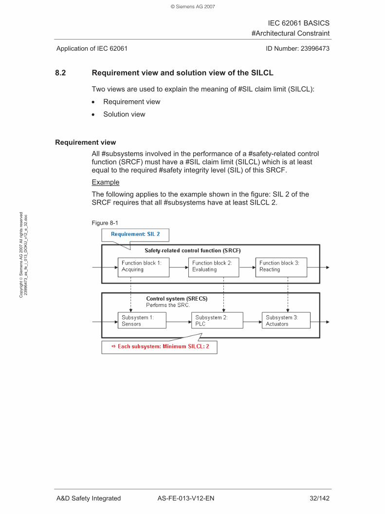
8.2 Requirement view and solution view of the SILCL
Two views are used to explain the meaning of #SIL claim limit (SILCL):
• Requirement view
• Solution view
Requirement view All #subsystems involved in the performance of a #safety-related control function (SRCF) must have a #SIL claim limit (SILCL) which is at least equal to the required #safety integrity level (SIL) of this SRCF.
Example
The following applies to the example shown in the figure: SIL 2 of the SRCF requires that all #subsystems have at least SILCL 2. Figure 8-1
© Siemens AG 2007

IEC 62061 BASICS#Architectural Constraint
Application of IEC 62061 ID Number: 23996473
A&D Safety Integrated AS-FE-013-V12-EN 33/142
Cop
yrig
ht ©
Sie
men
s A
G 2
007
All
right
s re
serv
ed
2399
6473
_as_
fe_i
_013
_DO
KU
_v12
_e_3
2.do
c
Solution view The maximum #safety integrity level (SIL) that can be achieved for a #safety-related control function (SRCF) corresponds to the smallest #SIL claim limit (SILCL) of all #subsystems involved in the performance of the SRCF.
Example
The following applies to the example shown in the figure: Due to #subsystem 1, the SIL that can be achieved for the SRCF is limited to maximally SIL 2.
Figure 8-2
8.3 Factors of influence on the SILCL
From the structure (architecture) of a #subsystem, the following characteristics ensue for this #subsystem:
• Hardware fault tolerance (HFT)
• #Safe failure fraction (SFF)
The #SIL claim limit (SILCL) of the #subsystem is determined from the two characteristics HFT and SFF.
Note: A central explanation of the terms “fault” and “failure” is given in chapter 27.6.
© Siemens AG 2007

IEC 62061 BASICS#Architectural Constraint
Application of IEC 62061 ID Number: 23996473
A&D Safety Integrated AS-FE-013-V12-EN 34/142
Cop
yrig
ht ©
Sie
men
s A
G 2
007
All
right
s re
serv
ed
2399
6473
_as_
fe_i
_013
_DO
KU
_v12
_e_3
2.do
c
8.3.1 Hardware fault tolerance (HFT)
Description The hardware fault tolerance (HFT) expresses the #fault tolerance of a #subsystem. #Fault tolerance is the ability of a #subsystem to continue to perform a required function also after faults have occurred.
Determination To determine the HFT, the hardware configuration of the #subsystem is considered. The HFT of a #subsystem expresses the tolerance of a #subsystem to faults in the hardware:
• A #subsystem with an HFT of N only fails after (N+1) faults have occurred.
A failure of a #subsystem causes the loss of all SRCFs using this #subsystem.
When determining the HFT, other measures are not considered which could control the effects of faults (example: Diagnostic devices.)
In general, the design of #subsystems with #fault tolerance is redundant. The following table and the following examples illustrate the correlations. Table 8-2
HFT of the #subsystem
Redundancy of the #subsystem
Number of faults in the #subsystem which cause the loss of the SRCF
0 No redundancy 1 fault 1 1-fold redundancy 2 faults 2 2-fold redundancy 3 faults N N-fold redundancy (N+1) faults
© Siemens AG 2007

IEC 62061 BASICS#Architectural Constraint
Application of IEC 62061 ID Number: 23996473
A&D Safety Integrated AS-FE-013-V12-EN 35/142
Cop
yrig
ht ©
Sie
men
s A
G 2
007
All
right
s re
serv
ed
2399
6473
_as_
fe_i
_013
_DO
KU
_v12
_e_3
2.do
c
Example of a #subsystem with HFT = 0 (#subsystem without #fault tolerance)
The #subsystem consists of one single #subsystem element:
• 1 contactor for switching off a motor
A fault in the #subsystem (contactor does not open) has the following effect:
• 1 fault in the #subsystem
• Failure of the #subsystem (the #subsystem can no longer perform its function.)
• Loss of all SRCFs using this #subsystem (the SRCFs are no longer performed because the #subsystem no longer complies with its function.)
Example of a #subsystem with HFT = 1 (#subsystem with #fault tolerance)
The #subsystem consists of two #subsystem elements:
• 2 contactors in series for switching off a motor
A fault in the #subsystem (1 contactor does not open) has the following effect:
• 1 fault in the #subsystem
• No failure of the #subsystem
• No loss of a SRCF
© Siemens AG 2007

IEC 62061 BASICS#Architectural Constraint
Application of IEC 62061 ID Number: 23996473
A&D Safety Integrated AS-FE-013-V12-EN 36/142
Cop
yrig
ht ©
Sie
men
s A
G 2
007
All
right
s re
serv
ed
2399
6473
_as_
fe_i
_013
_DO
KU
_v12
_e_3
2.do
c
8.3.2 #Safe failure fraction (SFF)
Description Failures are caused by random faults in the hardware of the #safety system (SRECS) or its #subsystems.
The failure of a #subsystem causes a loss of the #safety-related control functions (SRCFs) which use this #subsystem.
Failures of a #subsystem can be safe or dangerous, depending on the effect on the machine. The following table illustrates the differences. Table 8-3
Effect on Failure mode of a #subsystem SRCF State on machine / #safety function
#Safe failure Loss of the SRCF
The failure does not cause a dangerous state. The #safety function does not fail.
#Dangerous failure Loss of the SRCF
The failure may cause a dangerous state. The #safety function may fail.
In the event of a #safe failure, the #safety function remains. This is achieved by the following measures:
• Fault detection (diagnostics) and corresponding fault reaction
The #safe failure fraction (SFF) describes the fraction of #safe failures of a #subsystem in the overall failure rate of the #subsystem.
© Siemens AG 2007

IEC 62061 BASICS#Architectural Constraint
Application of IEC 62061 ID Number: 23996473
A&D Safety Integrated AS-FE-013-V12-EN 37/142
Cop
yrig
ht ©
Sie
men
s A
G 2
007
All
right
s re
serv
ed
2399
6473
_as_
fe_i
_013
_DO
KU
_v12
_e_3
2.do
c
To determine the SFF, an analysis of the #subsystem has to be performed. In the analysis, the following is determined:
• All faults that can actually occur
• The failure modes and their fractions
• The rate (probability) of each failure mode
Depending on the complexity of the #subsystem, the method for the analysis of the #subsystem differs: Table 8-4
#Subsystem Method
Complex #subsystem Examples of methods: • Fault tree analysis • Failure mode analysis • Effects analysis
Simple #subsystem (#subsystem with electromechanical components such as contactor or position switch)
Simpler methods can be used here. The failure modes to be considered are, for example, listed in Annex D of IEC 62061 (chapter 27.3).
SFF determination Table 8-5
Short description of SFF
Symbol SFF Designation #Safe failure fraction Meaning SFF indicates for a #subsystem how many percent of all failures are safe
failures. Safe failures do not cause a dangerous state on the machine. SFF refers to the #subsystem. For #subsystems with several identical #subsystem elements, it is sufficient to consider one #subsystem element by itself.
Definition See tables below. Example SFF = 0.9
Meaning: • 90% of all failures are safe failures and do not cause a dangerous
state on the machine. • 10% of all failures may cause a dangerous state on the machine.
© Siemens AG 2007

IEC 62061 BASICS#Architectural Constraint
Application of IEC 62061 ID Number: 23996473
A&D Safety Integrated AS-FE-013-V12-EN 38/142
Cop
yrig
ht ©
Sie
men
s A
G 2
007
All
right
s re
serv
ed
2399
6473
_as_
fe_i
_013
_DO
KU
_v12
_e_3
2.do
c
Table 8-6
Calculation of SFF
Formula SFF = (λtotal - λDUtotal) / λtotal
Dimensionless Dimension The SFF is also indicated as a percentage. This requires that the result is
converted: 0.x -> 0.x * 100%. Example: 0.1 -> 10%
Table 8-7
Explanations of the SFF formula
λtotal = ΣλS+ ΣλD Designation Rate of all failures of the #subsystem (overall failure rate of the #subsystem) Meaning ---
λDUtotal = Σ λDU Designation Rate of all dangerous failures not detected by diagnostics. Meaning These failures may cause a dangerous state on the machine.
λD = λDD + λDU Designation Dangerous failure rate Meaning These failures may cause a dangerous state on the machine.
Table 8-8
Parameters for calculating the SFF
λDU Designation Dangerous failure rate not detected by diagnostics. Meaning These failures may cause a dangerous state on the machine.
λDD
Designation Dangerous failure rate detected by diagnostics. Meaning These failures may cause a dangerous state on the machine.
λS
Designation Safe failure rate Meaning These failures do not cause a dangerous state on the machine. The following statements apply to all parameters listed above: Definition The definition requires that the different failure modes and their fractions are
known. The following sources can be used: • Manufacturer documentation • IEC 62061, Annex D (chapter 27.3)
Calculation Principle: See chapter 9.7.1 Dimension 1 / h (per hour)
© Siemens AG 2007

IEC 62061 BASICS#Architectural Constraint
Application of IEC 62061 ID Number: 23996473
A&D Safety Integrated AS-FE-013-V12-EN 39/142
Cop
yrig
ht ©
Sie
men
s A
G 2
007
All
right
s re
serv
ed
2399
6473
_as_
fe_i
_013
_DO
KU
_v12
_e_3
2.do
c
8.4 Options for determining the SILCL
There are different options for determining the #SIL claim limit (SILCL) of a #subsystem. In the following, a differentiation is made between:
• Finished #subsystem
• Designed #subsystem
Finished #subsystem In this case, the IEC 62061 user (machine manufacturer, control integrator) purchases the finished #subsystem from the manufacturer (table 4-2).
When purchasing a finished #subsystem, the user is generally provided with a manufacturer documentation from which he/she can derive the #SIL claim limit (SILCL). Table 8-9
Manufacturer information on the #subsystem
SILCL determination Details in chapter
SILCL
The SILCL is directly applied. ---
Category according to EN 954-1 (Chapter 27.7)
The SILCL is determined using a table from IEC 62061.
8.5
HFT, SFF The SILCL is determined using a table from IEC 62061.
8.6
Designed #subsystem In this case, the IEC 62061 user (machine manufacturer, control integrator) assembles his/her #subsystem from #subsystem elements (table 4-2).
A designed #subsystem requires that the user determines the #SIL claim limit (SILCL) of his/her #subsystem.
Chapter 8.7 describes the basic calculation.
© Siemens AG 2007

IEC 62061 BASICS#Architectural Constraint
Application of IEC 62061 ID Number: 23996473
A&D Safety Integrated AS-FE-013-V12-EN 40/142
Cop
yrig
ht ©
Sie
men
s A
G 2
007
All
right
s re
serv
ed
2399
6473
_as_
fe_i
_013
_DO
KU
_v12
_e_3
2.do
c
8.5 Finished #subsystem: SILCL determination from the category
If the manufacturer provides a category according to EN 954-1 for the #subsystem, the #subsystem’s #SIL claim limit (SILCL) can be derived from this information.
To do this, the following table (IEC 62061, table 6) is used. Table 8-10
Assumption: #Subsystems with category x
have the properties
#Subsystem category
HFT SFF
SILCL
1 0 < 60% - 2 0 60% to 90% 3 1 < 60%
SILCL 1
3 1 60% to 90% SILCL 2 4 > 1 60% to 90% 4 1 > 90%
SILCL 3
Application of the above table: Table 8-11
Data Remark
Input data of the table Category Information of the manufacturer Output data of the table SILCL #SIL claim limit (SILCL)
Explanations of the above table: Table 8-12
For the determination of: See chapter:
Hardware fault tolerance (HFT) 8.3.1 #Safe failure fraction (SFF) 8.3.2
8.6 Finished #subsystem: SILCL determination from HFT and SFF
If the manufacturer provides the characteristics hardware fault tolerance (HFT) and #safe failure fraction (SFF) for the #subsystem, the #subsystem’s #SIL claim limit (SILCL) can be derived from this information.
To do this, table 8-13 (IEC 62061, table 5, modified) is used.
© Siemens AG 2007

IEC 62061 BASICS#Architectural Constraint
Application of IEC 62061 ID Number: 23996473
A&D Safety Integrated AS-FE-013-V12-EN 41/142
Cop
yrig
ht ©
Sie
men
s A
G 2
007
All
right
s re
serv
ed
2399
6473
_as_
fe_i
_013
_DO
KU
_v12
_e_3
2.do
c
8.7 Designed #subsystem: SILCL determination from HFT and SFF
When designing a #subsystem from #subsystem elements, proceed as follows to determine the #SIL claim limit (SILCL):
• HFT determination: See chapter 8.3.1.
• SFF determination: See chapter 8.3.2.
• Derivation of SILCL from HFT and SFF: See below.
The #SIL claim limit (SILCL) of the #subsystem can be derived from the hardware fault tolerance (HFT) and the #safe failure fraction (SFF).
To do this, the following table (IEC 62061, table 5, modified) is used. Table 8-13
HFT
0 1 2
< 60% Not allowed SILCL 1 SILCL 2 60% to < 90% SILCL 1 SILCL 2 SILCL 3 90% to < 99% SILCL 2 SILCL 3 SILCL 3
SFF
>= 99% SILCL 3 SILCL 3 SILCL 3
Application of the above table: Table 8-14
Data Remark
HFT Hardware fault tolerance (HFT) Input data of the table SFF #Safe failure fraction (SFF)
Output data of the table SILCL #SIL claim limit (SILCL)
The above table indicates that there are different combinations of SFF and HFT for a specific SILCL value. A specific SILCL can thus be achieved with different structures of a #subsystem.
Examples
Example 1: A #subsystem without redundancy (HFT = 0) must have a high SFF (SFF >= 99%) to achieve SILCL 3.
Example 2: For a #subsystem with high redundancy (HFT = 2), a smaller SFF (SFF = 60%) is sufficient to achieve SILCL 3.
© Siemens AG 2007

IEC 62061 BASICS#PFHD Value (PFHD)
Application of IEC 62061 ID Number: 23996473
A&D Safety Integrated AS-FE-013-V12-EN 42/142
Cop
yrig
ht ©
Sie
men
s A
G 2
007
All
right
s re
serv
ed
2399
6473
_as_
fe_i
_013
_DO
KU
_v12
_e_3
2.do
c
9 #PFHD Value (PFHD)
9.1 Meaning of PFHD
Failures of safety devices on a machine may implicate hazards. The occurrence of such dangerous failures is more or less probable. A dimension for the occurrence is the #PFHD value (PFHD).
PFHD is generally defined as:
• Probability of dangerous failure per hour.
The #PFHD value (PFHD) is applied to:
• #Safety-related control functions (SRCFs)
• #Subsystems of a safety system (SRECS)
The correlations are explained in the following table. Table 9-1
#PFHD value (PFHD) Explanation
PFHD of a SRCF A SRCF can fail. “Failure of a SRCF” means that the SRCF no longer performs its function. PFHD is a dimension for the probability of failure of a SRCF.
PFHD of a #subsystem
A #subsystem can fail. “Failure of a #subsystem” means that the #subsystem no longer performs its function. The failure of a #subsystem means the failure of all SRCFs using this #subsystem. PFHD is a dimension for the probability of failure of a #subsystem.
© Siemens AG 2007

IEC 62061 BASICS#PFHD Value (PFHD)
Application of IEC 62061 ID Number: 23996473
A&D Safety Integrated AS-FE-013-V12-EN 43/142
Cop
yrig
ht ©
Sie
men
s A
G 2
007
All
right
s re
serv
ed
2399
6473
_as_
fe_i
_013
_DO
KU
_v12
_e_3
2.do
c
9.2 Correlation: SIL and PFHD of a SRCF
In the risk assessment (chapter 15), one #safety integrity level (SIL) is defined for each #safety-related control function (SRCF) which has to be met by the SRCF.
Limit values for the maximum permissible #PFHD value (PFHD) are assigned to each SIL.
• The requirements for the reliability of the SRCF increase with an increasing SIL, which is shown by a smaller maximum permissible #PFHD value (PFHD).
• The requirements for the reliability of the SRCF decrease with a decreasing SIL, which is shown by a larger maximum permissible #PFHD value (PFHD).
The table below (IEC 62061, table 3) shows the correlation between #safety integrity level (SIL) and #PFHD value (PFHD) of a #safety-related control function (SRCF). Table 9-2
#Safety integrity level (SIL) #PFHD value
SIL 3 10-8 ≥ PFHD < 10-7 SIL 2 10-7 ≥ PFHD < 10-6 SIL 1 10-6 ≥ PFHD < 10-5
© Siemens AG 2007

IEC 62061 BASICS#PFHD Value (PFHD)
Application of IEC 62061 ID Number: 23996473
A&D Safety Integrated AS-FE-013-V12-EN 44/142
Cop
yrig
ht ©
Sie
men
s A
G 2
007
All
right
s re
serv
ed
2399
6473
_as_
fe_i
_013
_DO
KU
_v12
_e_3
2.do
c
9.3 Calculating the PFHD of a SRCF
A #safety-related control function (SRCF) is performed by #subsystems of a #safety system (SRECS).
The #PFHD value (PFHD) of a SRCF is calculated from:
• The sum of the PFHD of the involved #subsystems and
• the probability of dangerous transmission errors for digital communication processes (example: The F-PLC communicates with the sensors and actuators via PROFIBUS DP)
The figure below illustrates the principle.
Figure 9-1
© Siemens AG 2007

IEC 62061 BASICS#PFHD Value (PFHD)
Application of IEC 62061 ID Number: 23996473
A&D Safety Integrated AS-FE-013-V12-EN 45/142
Cop
yrig
ht ©
Sie
men
s A
G 2
007
All
right
s re
serv
ed
2399
6473
_as_
fe_i
_013
_DO
KU
_v12
_e_3
2.do
c
9.4 Options for determining the PFHD of a #subsystem
There are different options for determining the #PFHD value (PFHD) of a #subsystem. In the following, a differentiation is made between:
• Finished #subsystem
• Designed #subsystem
Finished #subsystem In this case, the IEC 62061 user (machine manufacturer, control integrator) purchases the finished #subsystem from the manufacturer (table 4-2).
When purchasing a finished #subsystem, the user is generally provided with a manufacturer documentation from which he/she can derive the PFHD. Table 9-3
Manufacturer information on the #subsystem
SILCL determination Details in chapter
PFHD
The PFHD is directly applied. ---
Category according to EN 954-1 (Chapter 27.7)
The PFHD is determined using table 7 from IEC 62061.
9.5
Designed #subsystem In this case, the IEC 62061 user (machine manufacturer, control integrator) assembles his/her #subsystem from #subsystem elements (table 4-2).
A designed #subsystem requires that the user determines the PFHD of his/her #subsystem.
Chapter 9.6 describes the basic calculation.
© Siemens AG 2007

IEC 62061 BASICS#PFHD Value (PFHD)
Application of IEC 62061 ID Number: 23996473
A&D Safety Integrated AS-FE-013-V12-EN 46/142
Cop
yrig
ht ©
Sie
men
s A
G 2
007
All
right
s re
serv
ed
2399
6473
_as_
fe_i
_013
_DO
KU
_v12
_e_3
2.do
c
9.5 Finished #subsystem: PFHD determination from the category
If the manufacturer provides a category for the #subsystem, the #subsystem’s #PFHD value (PFHD) can be derived from this information.
To do this, the following table (IEC 62061, table 7) is used. Table 9-4
Assumption: #Subsystems with category x
have the properties
#Subsystem category
HFT DC
PFHD
1 0 0% To be provided by manufacturer or use generic data (IEC 62061, Annex D).
2 0 60% to 90% ≥ 10-6
3 1 60% to 90% ≥ 2 * 10-7
4 > 1 60% to 90% ≥ 3 * 10-8
4 1 > 90% ≥ 3 * 10-8
Application of the above table: Table 9-5
Data Remark
Input data of the table Category Information of the manufacturer
Output data of the table PFHD #PFHD value (PFHD)
Explanations of the above table: Table 9-6
For the determination of: See chapter:
Hardware fault tolerance (HFT) 8.3.1 #Diagnostic coverage (DC) 9.7.3
© Siemens AG 2007

IEC 62061 BASICS#PFHD Value (PFHD)
Application of IEC 62061 ID Number: 23996473
A&D Safety Integrated AS-FE-013-V12-EN 47/142
Cop
yrig
ht ©
Sie
men
s A
G 2
007
All
right
s re
serv
ed
2399
6473
_as_
fe_i
_013
_DO
KU
_v12
_e_3
2.do
c
9.6 Designed #subsystem: PFHD calculation
Basic subsystem architectures For four architectures of simple #subsystems, IEC 62061 (chapter 6.7.8.2) provides finished formulae for calculating the #PFHD value (PFHD).
In practical operation, almost every simple #subsystem can be covered by the IEC 62061 basic subsystem architectures.
Characteristics of the basic subsystem architectures The table provides an overview of the basic subsystem architectures. Table 9-7
CharacteristicsBasic subsystem architecture
Hardware fault tolerance (HFT)
Diagnostic function
Number of #subsystem elements (*1) (*2) (*3)
A 0 No 1 to n x
C 0 Yes 1 to n x x B 1 No 2 x D 1 Yes 2 x x
Description of the characteristics: Table 9-8
Characteristic
(*1) The failure of one single #subsystem element causes the failure of the #subsystem and thus the loss of the SRCF.
(*2) The diagnostic function detects the failure of a #subsystem element and initiates a fault reaction.
(*3) The failure of one single #subsystem element does not cause the failure of the #subsystem and thus not the loss of the SRCF.
© Siemens AG 2007
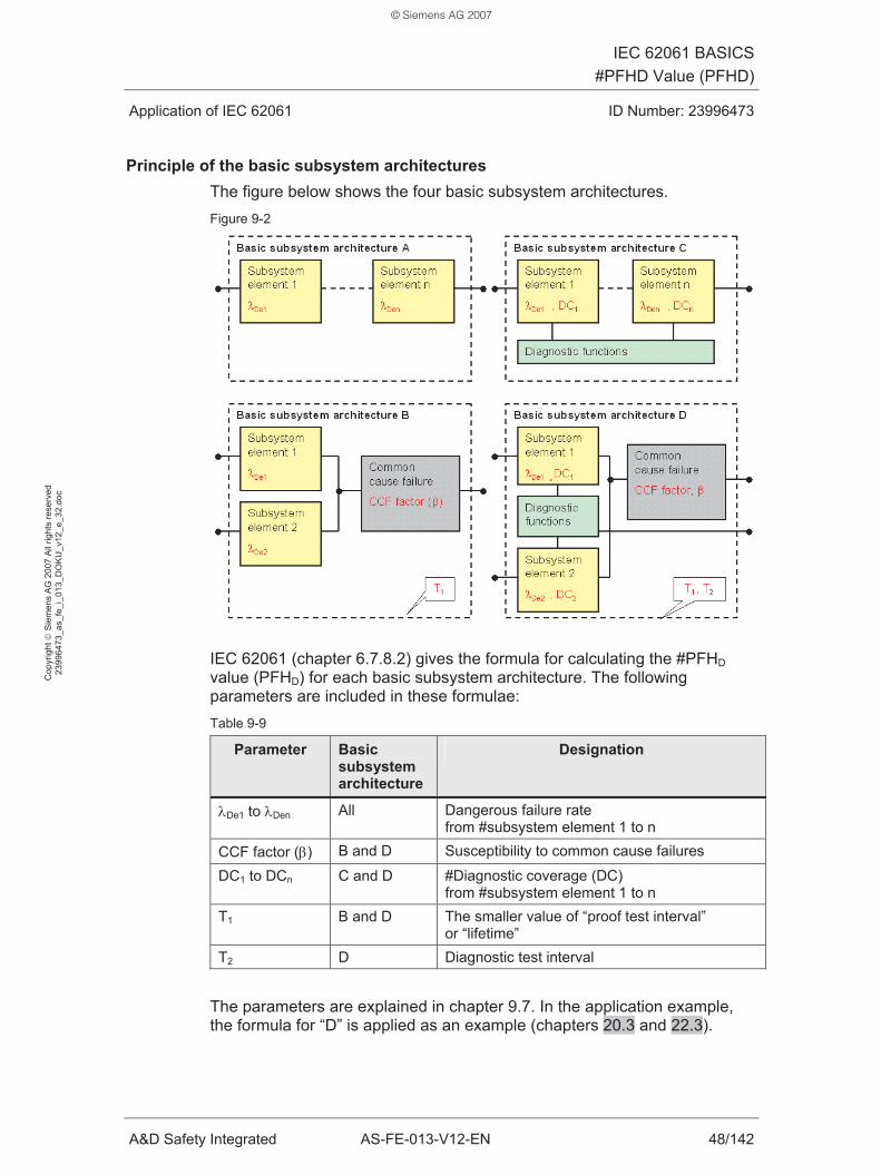
IEC 62061 BASICS#PFHD Value (PFHD)
Application of IEC 62061 ID Number: 23996473
A&D Safety Integrated AS-FE-013-V12-EN 48/142
Cop
yrig
ht ©
Sie
men
s A
G 2
007
All
right
s re
serv
ed
2399
6473
_as_
fe_i
_013
_DO
KU
_v12
_e_3
2.do
c
Principle of the basic subsystem architectures The figure below shows the four basic subsystem architectures. Figure 9-2
IEC 62061 (chapter 6.7.8.2) gives the formula for calculating the #PFHD value (PFHD) for each basic subsystem architecture. The following parameters are included in these formulae: Table 9-9
Parameter Basic subsystem architecture
Designation
λDe1 to λDen All Dangerous failure rate from #subsystem element 1 to n
CCF factor (β) B and D Susceptibility to common cause failures
DC1 to DCn C and D #Diagnostic coverage (DC) from #subsystem element 1 to n
T1 B and D The smaller value of “proof test interval” or “lifetime”
T2 D Diagnostic test interval
The parameters are explained in chapter 9.7. In the application example, the formula for “D” is applied as an example (chapters 20.3 and 22.3).
© Siemens AG 2007

IEC 62061 BASICS#PFHD Value (PFHD)
Application of IEC 62061 ID Number: 23996473
A&D Safety Integrated AS-FE-013-V12-EN 49/142
Cop
yrig
ht ©
Sie
men
s A
G 2
007
All
right
s re
serv
ed
2399
6473
_as_
fe_i
_013
_DO
KU
_v12
_e_3
2.do
c
Examples of the basic subsystem architectures Examples of the basic subsystem architectures are shown for clarification.
The examples apply to the following boundary conditions:
• The #subsystem has the function: “Switch off motor”.
• The #subsystem consists of one or two #subsystem elements.
• The #subsystem element is a contactor.
• Diagnostics of the contactor are performed by evaluating the contactor’s readback signals.
Table 9-10
Basic subsystem architecture
Example
A Contactor C Contactor with evaluation of the readback signals B Two contactors in series D Two contactors in series, with evaluation of the
readback signals
9.7 Influence on the PFHD of a #subsystem
Depending on the present basic subsystem architecture, different formulae are used to calculate the #PFHD value (PFHD) of a #subsystem.
The following parameters are included in the formulae:
• Dangerous failure rate of a #subsystem element (λDe1 to λDen)
• CCF factor (β)
• #Diagnostic coverage (DC) and diagnostic test interval
• Lifetime and proof test interval (T1)
These parameters will be described in the following.
© Siemens AG 2007

IEC 62061 BASICS#PFHD Value (PFHD)
Application of IEC 62061 ID Number: 23996473
A&D Safety Integrated AS-FE-013-V12-EN 50/142
Cop
yrig
ht ©
Sie
men
s A
G 2
007
All
right
s re
serv
ed
2399
6473
_as_
fe_i
_013
_DO
KU
_v12
_e_3
2.do
c
9.7.1 Dangerous failure rate of a #subsystem element (λDe)
The following considerations apply to electromechanical #subsystem elements (examples: Contactor, position switch).
A #subsystem of a #safety system (SRECS) can consist of one or several #subsystem elements. The #subsystem elements can be identical or different.
The λDe “dangerous failure rate” is calculated for each #subsystem element. This value is then included in the formula for calculating the #PFHD value (PFHD) of a #subsystem.
The calculation is performed in two steps: Table 9-11
Step Calculation
1 Failure rate of #subsystem element λ 2 Dangerous failure rate of #subsystem element λDe
The figure below shows the calculation principle. Figure 9-3
© Siemens AG 2007

IEC 62061 BASICS#PFHD Value (PFHD)
Application of IEC 62061 ID Number: 23996473
A&D Safety Integrated AS-FE-013-V12-EN 51/142
Cop
yrig
ht ©
Sie
men
s A
G 2
007
All
right
s re
serv
ed
2399
6473
_as_
fe_i
_013
_DO
KU
_v12
_e_3
2.do
c
1st step: Failure rate of #subsystem element λ Table 9-12
Short description of λ
Symbol λ Designation Failure rate of a #subsystem element Meaning Number of #subsystem element failures per hour Definition See tables below. Example λ = 10-8 / h
Meaning: One failure in 108 hours. Table 9-13
Calculation of λ
Formula λ = 0.1 * C / B10 Dimension 1 / h (per hour)
Table 9-14
Parameters of λ
B10 Designation B10 value of the #subsystem element. Meaning B10 is the number of switching cycles
after which 10% of the test objects have failed. Definition #Subsystem element manufacturer Dimension Dimensionless
C Designation - Meaning Number of #subsystem element operations per hour Definition Specification of the #safety-related
control function (SRCF). Dimension 1 / h (per hour)
© Siemens AG 2007

IEC 62061 BASICS#PFHD Value (PFHD)
Application of IEC 62061 ID Number: 23996473
A&D Safety Integrated AS-FE-013-V12-EN 52/142
Cop
yrig
ht ©
Sie
men
s A
G 2
007
All
right
s re
serv
ed
2399
6473
_as_
fe_i
_013
_DO
KU
_v12
_e_3
2.do
c
2nd step: Dangerous failure rate of #subsystem element λDe Table 9-15
Short description of λDe
Symbol λDe
Designation Dangerous failure rate of the #subsystem element Meaning Number of dangerous #subsystem element failures per hour. Definition See tables below. Example λDe = 10-9 / h
Meaning: One dangerous failure in 109 hours. Table 9-16
Calculation of λDe
Formula λDe = (dangerous failure fraction) * λ Dimension 1 / h (per hour)
Table 9-17
Parameters of λDe
Dangerous failure fraction Designation - Meaning Dangerous failure fraction of the #subsystem element
in all #subsystem element failures. Definition The definition requires that the different fault types and their
fractions are known. The following sources can be used: • Manufacturer documentation • IEC 62061, Annex D (chapter 27.3) Dimensionless Dimension The “dangerous failure fraction” is normally indicated as a percentage. The value has to be converted for the formula: x% -> x% / 100%. Example: 10% -> 0.1
λ
See table 9-13: Calculation of failure rate λ.
© Siemens AG 2007
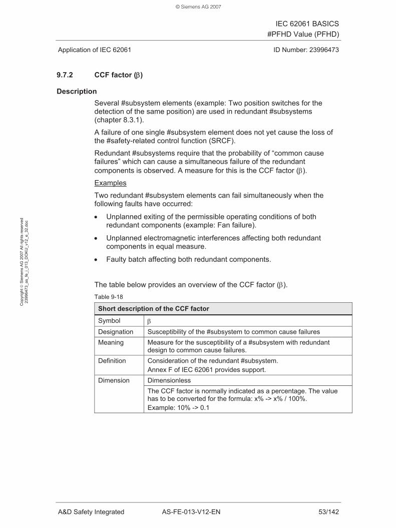
IEC 62061 BASICS#PFHD Value (PFHD)
Application of IEC 62061 ID Number: 23996473
A&D Safety Integrated AS-FE-013-V12-EN 53/142
Cop
yrig
ht ©
Sie
men
s A
G 2
007
All
right
s re
serv
ed
2399
6473
_as_
fe_i
_013
_DO
KU
_v12
_e_3
2.do
c
9.7.2 CCF factor (β)
Description Several #subsystem elements (example: Two position switches for the detection of the same position) are used in redundant #subsystems (chapter 8.3.1).
A failure of one single #subsystem element does not yet cause the loss of the #safety-related control function (SRCF).
Redundant #subsystems require that the probability of “common cause failures” which can cause a simultaneous failure of the redundant components is observed. A measure for this is the CCF factor (β).
Examples
Two redundant #subsystem elements can fail simultaneously when the following faults have occurred:
• Unplanned exiting of the permissible operating conditions of both redundant components (example: Fan failure).
• Unplanned electromagnetic interferences affecting both redundant components in equal measure.
• Faulty batch affecting both redundant components.
The table below provides an overview of the CCF factor (β). Table 9-18
Short description of the CCF factor
Symbol β Designation Susceptibility of the #subsystem to common cause failures Meaning Measure for the susceptibility of a #subsystem with redundant
design to common cause failures. Definition Consideration of the redundant #subsystem.
Annex F of IEC 62061 provides support. Dimensionless Dimension The CCF factor is normally indicated as a percentage. The value has to be converted for the formula: x% -> x% / 100%. Example: 10% -> 0.1
© Siemens AG 2007
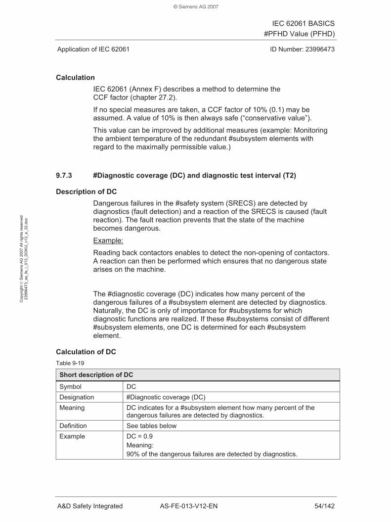
IEC 62061 BASICS#PFHD Value (PFHD)
Application of IEC 62061 ID Number: 23996473
A&D Safety Integrated AS-FE-013-V12-EN 54/142
Cop
yrig
ht ©
Sie
men
s A
G 2
007
All
right
s re
serv
ed
2399
6473
_as_
fe_i
_013
_DO
KU
_v12
_e_3
2.do
c
Calculation IEC 62061 (Annex F) describes a method to determine the CCF factor (chapter 27.2).
If no special measures are taken, a CCF factor of 10% (0.1) may be assumed. A value of 10% is then always safe (“conservative value”).
This value can be improved by additional measures (example: Monitoring the ambient temperature of the redundant #subsystem elements with regard to the maximally permissible value.)
9.7.3 #Diagnostic coverage (DC) and diagnostic test interval (T2)
Description of DC Dangerous failures in the #safety system (SRECS) are detected by diagnostics (fault detection) and a reaction of the SRECS is caused (fault reaction). The fault reaction prevents that the state of the machine becomes dangerous.
Example:
Reading back contactors enables to detect the non-opening of contactors. A reaction can then be performed which ensures that no dangerous state arises on the machine.
The #diagnostic coverage (DC) indicates how many percent of the dangerous failures of a #subsystem element are detected by diagnostics. Naturally, the DC is only of importance for #subsystems for which diagnostic functions are realized. If these #subsystems consist of different #subsystem elements, one DC is determined for each #subsystem element.
Calculation of DC Table 9-19
Short description of DC
Symbol DC Designation #Diagnostic coverage (DC) Meaning DC indicates for a #subsystem element how many percent of the
dangerous failures are detected by diagnostics. Definition See tables below Example DC = 0.9
Meaning: 90% of the dangerous failures are detected by diagnostics.
© Siemens AG 2007

IEC 62061 BASICS#PFHD Value (PFHD)
Application of IEC 62061 ID Number: 23996473
A&D Safety Integrated AS-FE-013-V12-EN 55/142
Cop
yrig
ht ©
Sie
men
s A
G 2
007
All
right
s re
serv
ed
2399
6473
_as_
fe_i
_013
_DO
KU
_v12
_e_3
2.do
c
Table 9-20
Calculation of DC
Formula DC = λDDtotal / λDtotal
Dimensionless Dimension The DC is also indicated as a percentage. This requires that the result is converted: 0.x -> 0.x * 100%. Example: 0.1 -> 10%
Table 9-21
Explanations of the DC formula
λDDtotal = Σ λDD Designation Rate of all dangerous failures detected by diagnostics. Meaning These failures may cause a dangerous state on the machine.
λDtotal = Σ λD Designation Rate of all dangerous failures Meaning ---
λD = λDD + λDU Designation Dangerous failure rate Meaning These failures may cause a dangerous state on the machine.
Table 9-22
Parameters of DC
λDD
Designation Dangerous failure rate detected by diagnostics. Meaning These failures may cause a dangerous state on the machine.
λDU
Designation Dangerous failure rate not detected by diagnostics. Meaning These failures may cause a dangerous state on the machine. The following statements apply to all parameters listed above Definition The definition requires that the different failure modes and their fractions are
known. The following sources can be used: • Manufacturer documentation • IEC 62061, Annex D (chapter 27.3)
Calculation Principle: See chapter 9.7.1 Dimension 1 / h (per hour)
© Siemens AG 2007

IEC 62061 BASICS#PFHD Value (PFHD)
Application of IEC 62061 ID Number: 23996473
A&D Safety Integrated AS-FE-013-V12-EN 56/142
Cop
yrig
ht ©
Sie
men
s A
G 2
007
All
right
s re
serv
ed
2399
6473
_as_
fe_i
_013
_DO
KU
_v12
_e_3
2.do
c
Diagnostic test interval (T2) To perform the diagnostics (fault detection), the #safety system (SRECS) performs tests at specific intervals. The interval between two tests is referred to as diagnostic test interval.
The table below provides an overview of the diagnostic test interval (T2). Table 9-23
Short description of T2
Symbol T2 Designation Diagnostic test interval Meaning - Definition Specification of the #safety-related
control function (SRCF). Example - Dimension h (hour)
9.7.4 Minimum of lifetime and proof test interval (T1)
Lifetime The lifetime is the time in which a #subsystem or a #subsystem element is used.
After the lifetime has expired, the #subsystem or the #subsystem element has to be replaced.
The table below provides an overview of the lifetime. Table 9-24
Short description of lifetime
Symbol - Designation Lifetime Meaning The time in which a #subsystem or a #subsystem element
is used. Definition Manufacturer of the #subsystem or #subsystem element. Range of validity
The value is of importance for electromechanical components (example: Position switch, contactor).
Dimension h (hour)
© Siemens AG 2007

IEC 62061 BASICS#PFHD Value (PFHD)
Application of IEC 62061 ID Number: 23996473
A&D Safety Integrated AS-FE-013-V12-EN 57/142
Cop
yrig
ht ©
Sie
men
s A
G 2
007
All
right
s re
serv
ed
2399
6473
_as_
fe_i
_013
_DO
KU
_v12
_e_3
2.do
c
Proof test interval The #proof test is a test (maintenance, inspection) that can detect the faults or a degradation in the #safety system (SRECS) and its #subsystems.
The #proof test is intended to detect dangerous faults which cannot be detected by automatic diagnostics. The proof test is performed manually at long intervals (depending on the application).
The interval between two manual tests is referred to as proof test interval. After the proof test interval has elapsed, the #safety system (SRECS) and its #subsystems have to be tested and restored to an “as new condition”.
The table below provides an overview of the proof test interval. Table 9-25
Short description of the proof test interval
Symbol - Designation Proof test interval Meaning Interval between two manual tests. Definition By manufacturer of the #subsystem or #subsystem element. Range of validity
The value is of importance for electronic and/or programmable components (example: F-PLC).
Dimension h (hour)
Example of lifetime and proof test interval For SIMATIC and SIRIUS components, this specifically means: Table 9-26
Components Relevant time interval
Normal value
Activity after the time interval has
elapsed
SIMATIC Proof test interval 10 years Test and update SIRIUS Lifetime 10 years Replacement
Minimum of lifetime and proof test interval: T1 T1 is the minimum of the two values for lifetime and proof test interval.
T1 is included in the formulae for calculating the #PFHD value (PFHD) (basic subsystem architectures B and D).
© Siemens AG 2007

IEC 62061 BASICS#PFHD Value (PFHD)
Application of IEC 62061 ID Number: 23996473
A&D Safety Integrated AS-FE-013-V12-EN 58/142
Cop
yrig
ht ©
Sie
men
s A
G 2
007
All
right
s re
serv
ed
2399
6473
_as_
fe_i
_013
_DO
KU
_v12
_e_3
2.do
c
9.8 Example: Formula for the PFHD value of basic subsystem architecture D
This chapter presents the formula for basic subsystem architecture D from IEC 62061. This formula will later be applied in the application example.
Characteristics of basic subsystem architecture D:
• With #fault tolerance (HFT = 1)
• With diagnostics
• Two #subsystem elements
Boundary conditions for the example:
• The two #subsystem elements are identical.
The #PFHD value (PFHD) is calculated in the following order:
• Consideration of the #subsystem element (chapter 9.7.1),
• consideration of the #subsystem
This procedure is illustrated in the figure below. Figure 9-4
The following sections describe 4 steps for calculating the #PFHD value (PFHD).
© Siemens AG 2007

IEC 62061 BASICS#PFHD Value (PFHD)
Application of IEC 62061 ID Number: 23996473
A&D Safety Integrated AS-FE-013-V12-EN 59/142
Cop
yrig
ht ©
Sie
men
s A
G 2
007
All
right
s re
serv
ed
2399
6473
_as_
fe_i
_013
_DO
KU
_v12
_e_3
2.do
c
1st step: Failure rate of #subsystem element λ Table 9-27
Calculation of λ
Formula λ = 0.1 * C / B10 Meaning Failure rate of the #subsystem element Description Chapter 9.7.1
Table 9-28
Parameters of λ
B10 Meaning B10 value of the #subsystem element
C Meaning Number of #subsystem element operations in h
2nd step: Dangerous failure rate of #subsystem element λDe Table 9-29
Calculation of λDe
Formula λDe = (dangerous failure fraction) * λ Meaning Dangerous failure rate of the #subsystem element Description Chapter 9.7.1
Table 9-30
Parameters of λDe
Dangerous failure fraction Meaning Dangerous failure fraction of the #subsystem element
λ Meaning See table 9-27: Failure rate of the #subsystem element
© Siemens AG 2007

IEC 62061 BASICS#PFHD Value (PFHD)
Application of IEC 62061 ID Number: 23996473
A&D Safety Integrated AS-FE-013-V12-EN 60/142
Cop
yrig
ht ©
Sie
men
s A
G 2
007
All
right
s re
serv
ed
2399
6473
_as_
fe_i
_013
_DO
KU
_v12
_e_3
2.do
c
3rd step: Dangerous failure rate of #subsystem λDssD Table 9-31
Calculation of λDssD
Formula λDssD = (1 - β )2 * {[ λDe2 * 2* DC ] * T2 / 2 + [ λDe
2 * (1 – DC) ] * T1} + β * λDe Meaning Dangerous failure rate of the #subsystem
Table 9-32
Parameters of λDssD
β (CCF factor) Meaning Susceptibility to common cause failures Description Chapter 9.7.2
T1 Meaning #Subsystem element lifetime Description Chapter 9.7.4
T2 Meaning Diagnostic test interval. Description Chapter 9.7.3
DC Meaning #Diagnostic coverage (DC) Description Chapter 9.7.3
λDe Meaning See table 9-30: Dangerous failure rate of the #subsystem element Description Chapter 9.7.1
4th step: #PFHD value (PFHD) of the #subsystem Table 9-33
Calculation of PFHD
Formula PFHD = λDssD * 1h Meaning #PFHD value (PFHD) of the #subsystem Dimension Dimensionless
Table 9-34
Parameters of PFHD
λDssD Meaning See table 9-31: Dangerous failure rate of the #subsystem Dimension 1 / h (per hour)
© Siemens AG 2007

IEC 62061 BASICS#Systematic Safety Integrity
Application of IEC 62061 ID Number: 23996473
A&D Safety Integrated AS-FE-013-V12-EN 61/142
Cop
yrig
ht ©
Sie
men
s A
G 2
007
All
right
s re
serv
ed
2399
6473
_as_
fe_i
_013
_DO
KU
_v12
_e_3
2.do
c
10 #Systematic Safety Integrity
IEC 62061 includes “#systematic safety integrity” requirements for the #safety system (SRECS) and its #subsystems.
The requirements are slightly graded according to the #safety integrity level (SIL). The requirements consist of:
• Avoidance of systematic faults
• Control of systematic faults
The table below shows examples of systematic faults. Table 10-1
Examples concern
Examples of systematic faults
Organization, management
• Defective design of the #safety system (SRECS) • No arrangement with regard to responsibilities
Engineering • Short circuit, wire break (of lines) • Overvoltage • Incorrect design: Component is unsuitable for the
application’s ambient conditions • Errors in the specification of application software or
hardware • Errors in the documentation for manufacturing
© Siemens AG 2007

IEC 62061 BASICS#Systematic Safety Integrity
Application of IEC 62061 ID Number: 23996473
A&D Safety Integrated AS-FE-013-V12-EN 62/142
Cop
yrig
ht ©
Sie
men
s A
G 2
007
All
right
s re
serv
ed
2399
6473
_as_
fe_i
_013
_DO
KU
_v12
_e_3
2.do
c
To meet the requirements of IEC 62061, specific measures have to be taken. The table below shows examples of such measures. Table 10-2
Examples concern
Examples of measures
Organization, management
Measures to avoid systematic faults: • Planning, defining responsibilities • Performing quality assurance • Reviewing documentation and application software • Complete and current documentation • Configuration and version management • Performing and documenting tests (validation) Measures to avoid systematic faults: • Using the components in the scope of the manufacturer’s
specification (observing, for example, maximum permissible ambient temperature).
• Acceptance according to manufacturer’s specifications (e.g. SIMATIC S7 Distributed Safety)
• Overdimensioning of components
Engineering
Measures to control systematic faults: • Monitoring during operation (e.g. monitoring the ambient
temperature or the insulation) • Tests by comparison when using redundant hardware • In the event of loss of the electrical supply, no dangerous
state must occur on the machine
© Siemens AG 2007

APPLICATIONApplication Example
Application of IEC 62061 ID Number: 23996473
A&D Safety Integrated AS-FE-013-V12-EN 63/142
Cop
yrig
ht ©
Sie
men
s A
G 2
007
All
right
s re
serv
ed
2399
6473
_as_
fe_i
_013
_DO
KU
_v12
_e_3
2.do
c
APPLICATION
11 Application Example
After the IEC 62061 basics have been explained in the previous chapters, the practical part of the document starts with this chapter. The document becomes concrete, IEC 62061 is applied. The used application example is briefly presented in this chapter.
11.1 Problem definition of the application example
The application example uses an example machine to show the basic application of IEC 62061.
Properties of the example machine • A blade rotates on the machine.
• A hinged protective cover is used as protection against the blade.
• For regular cleaning by the operator, the blade can be accessed by opening the protective cover.
Figure 11-1
Properties of the example machine’s automation • A fail-safe programmable logic controller (F-PLC) simultaneously
performs standard functions and #safety functions on the machine.
• “Only” the #safety function is considered since the document focuses on the application of IEC 62061. Standard functions required for normal operation of the machine are not considered.
Main focus of the application example • Derivation of the #safety function or the #safety-related control function
(SRCF)
• Realization of the #safety system (SRECS) performing the SRCF.
© Siemens AG 2007

APPLICATIONApplication Example
Application of IEC 62061 ID Number: 23996473
A&D Safety Integrated AS-FE-013-V12-EN 64/142
Cop
yrig
ht ©
Sie
men
s A
G 2
007
All
right
s re
serv
ed
2399
6473
_as_
fe_i
_013
_DO
KU
_v12
_e_3
2.do
c
11.2 Solution in the application example
The following section provides a brief overview of the solution shown step-by-step in the application example.
#Safety-related control function (SRCF) • Designation of the SRCF:
“Stop of the rotating blade”
• Function of the SRCF: When the protective cover is opened, the motor is switched off.
• Required #safety integrity level (SIL) of the SRCF: SIL 3
#Safety system (SRECS) The SRECS consists of 3 #subsystems: Table 11-1
#Subsystem Function Components
#Subsystem 1 Detecting the position of a protective cover via two position switches
SIRIUS
#Subsystem 2 Processing the signals with an F-PLC
SIMATIC S7 Distributed Safety
#Subsystem 3 Switching off the motor via two contactors
SIRIUS
#Subsystems 1 and 3 are designed #subsystems, #subsystem 2 is a finished #subsystem (table 4-2).
The figure below shows the structure (architecture) of the SRECS: Figure 11-2
© Siemens AG 2007

APPLICATIONApplication Example
Application of IEC 62061 ID Number: 23996473
A&D Safety Integrated AS-FE-013-V12-EN 65/142
Cop
yrig
ht ©
Sie
men
s A
G 2
007
All
right
s re
serv
ed
2399
6473
_as_
fe_i
_013
_DO
KU
_v12
_e_3
2.do
c
Boundary conditions Two already existing Functional Examples form the basis for the application example (/5/, chapter 29): Table 11-2
No. Title of the Functional Example ID Number
04 Safety Door without Guard Locking in Category 4 according to EN 954-1
21 33 13 63
07 Integration of the Readback Signal in an Application of Category 4 according to EN 954-1
21 33 10 98
#Subsystem 1 is based on Functional Example No. 04:
• Realization of the “Detection of the position of a protective cover via two position switches” function.
#Subsystem 3 is based on Functional Example No. 07:
• Realization of the “Read back contactors” diagnostic function.
© Siemens AG 2007
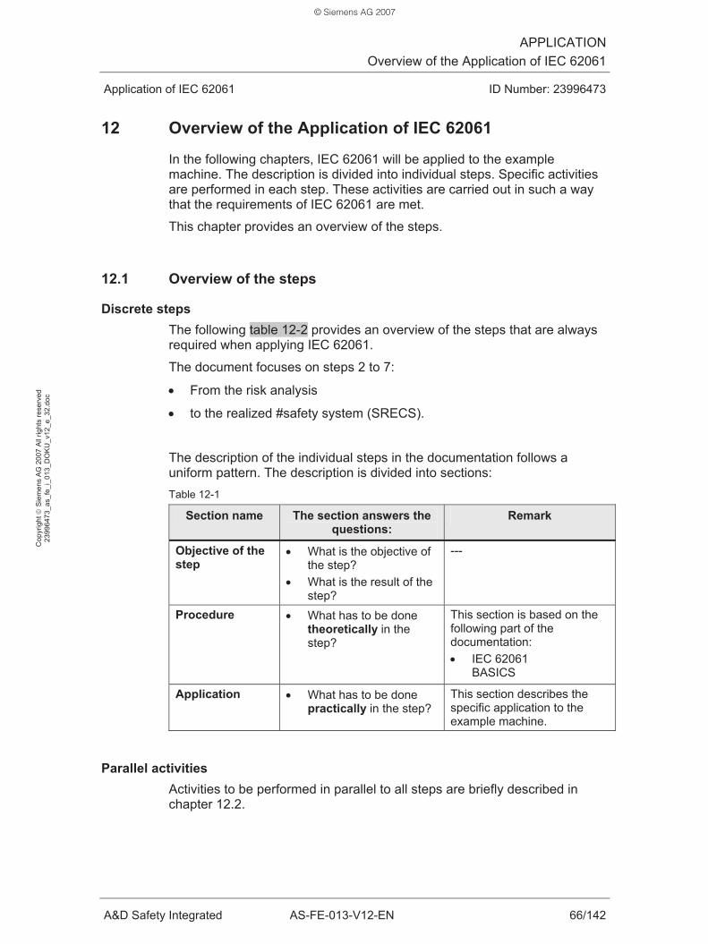
APPLICATIONOverview of the Application of IEC 62061
Application of IEC 62061 ID Number: 23996473
A&D Safety Integrated AS-FE-013-V12-EN 66/142
Cop
yrig
ht ©
Sie
men
s A
G 2
007
All
right
s re
serv
ed
2399
6473
_as_
fe_i
_013
_DO
KU
_v12
_e_3
2.do
c
12 Overview of the Application of IEC 62061
In the following chapters, IEC 62061 will be applied to the example machine. The description is divided into individual steps. Specific activities are performed in each step. These activities are carried out in such a way that the requirements of IEC 62061 are met.
This chapter provides an overview of the steps.
12.1 Overview of the steps
Discrete steps The following table 12-2 provides an overview of the steps that are always required when applying IEC 62061.
The document focuses on steps 2 to 7:
• From the risk analysis
• to the realized #safety system (SRECS).
The description of the individual steps in the documentation follows a uniform pattern. The description is divided into sections: Table 12-1
Section name The section answers the questions:
Remark
Objective of the step
• What is the objective of the step?
• What is the result of the step?
---
Procedure
• What has to be done theoretically in the step?
This section is based on the following part of the documentation: • IEC 62061
BASICS
Application
• What has to be done practically in the step?
This section describes the specific application to the example machine.
Parallel activities Activities to be performed in parallel to all steps are briefly described in chapter 12.2.
© Siemens AG 2007

APPLICATIONOverview of the Application of IEC 62061
Application of IEC 62061 ID Number: 23996473
A&D Safety Integrated AS-FE-013-V12-EN 67/142
Cop
yrig
ht ©
Sie
men
s A
G 2
007
All
right
s re
serv
ed
2399
6473
_as_
fe_i
_013
_DO
KU
_v12
_e_3
2.do
c
Overview of the steps necessary for the application of IEC 62016: Table 12-2
Step x: Activity
Chapter Standard Subject of the step
Step 1: Creating #Safety Plan
13 IEC 62061, chapter 4
Entire project
Step 2: Performing Risk Analysis
14 EN ISO 12100, EN 1050 EN ISO 12100, EN 1050
Step 3: Performing Risk Assessment
15
IEC 62061, Annex A
Step 4: Developing SRCF Specification
16 IEC 62061, chapter 5
Requirements from the
perspective of the machine
Step 5: Designing SRECS Architecture
17 IEC 62061, chapter 6
Objective, procedure
18
Overview #subsystems
19
Design #subsystem 1
20
Design #subsystem 2
21
Step 6: Realizing #Subsystems
Design #subsystem 3
22
IEC 62061, chapter 6.7
Step 7: Determining Achieved SIL
23 IEC 62061, chapter 6.6.3
Step 8: Implementing Hardware
IEC 62061, chapter 6.9
Step 9: Specifying Software
IEC 62061, chapter 6.10
Step 10: Designing / Developing Software
24 IEC 62061, chapter 6.11
Step 11: Integrating and Testing
IEC 62061, chapter 6.12
Step 12: Installing
IEC 62061, chapter 6.13
Step 13: Generating Information for Use
25 IEC 62061, chapter 7
Step 14: Performing Validation
26 IEC 62061, chapter 8
Solution from the
perspective of the SRECS
Main focus of the document
Interface machine / SRECS
© Siemens AG 2007
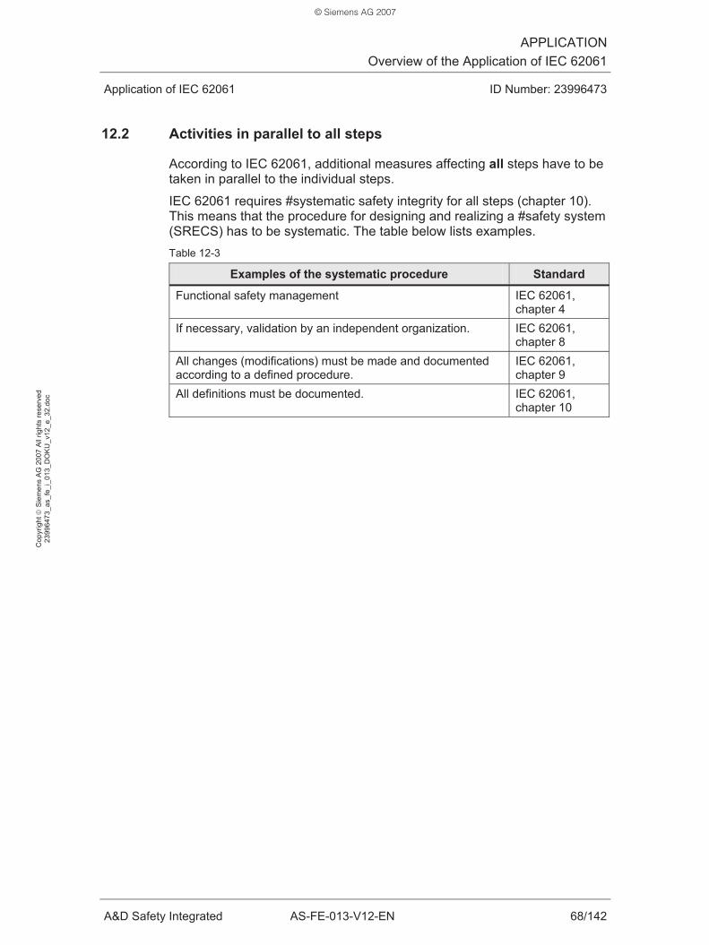
APPLICATIONOverview of the Application of IEC 62061
Application of IEC 62061 ID Number: 23996473
A&D Safety Integrated AS-FE-013-V12-EN 68/142
Cop
yrig
ht ©
Sie
men
s A
G 2
007
All
right
s re
serv
ed
2399
6473
_as_
fe_i
_013
_DO
KU
_v12
_e_3
2.do
c
12.2 Activities in parallel to all steps
According to IEC 62061, additional measures affecting all steps have to be taken in parallel to the individual steps.
IEC 62061 requires #systematic safety integrity for all steps (chapter 10). This means that the procedure for designing and realizing a #safety system (SRECS) has to be systematic. The table below lists examples. Table 12-3
Examples of the systematic procedure Standard
Functional safety management IEC 62061, chapter 4
If necessary, validation by an independent organization. IEC 62061, chapter 8
All changes (modifications) must be made and documented according to a defined procedure.
IEC 62061, chapter 9
All definitions must be documented.
IEC 62061, chapter 10
© Siemens AG 2007

APPLICATIONStep 1: Creating #Safety Plan
Application of IEC 62061 ID Number: 23996473
A&D Safety Integrated AS-FE-013-V12-EN 69/142
Cop
yrig
ht ©
Sie
men
s A
G 2
007
All
right
s re
serv
ed
2399
6473
_as_
fe_i
_013
_DO
KU
_v12
_e_3
2.do
c
13 Step 1: Creating #Safety Plan
The #safety plan is the bracket for all activities required for the realization of a #safety system (SRECS) on a machine.
13.1 Objective of the step
IEC 62061 requires a systematic procedure when realizing a #safety system (SRECS). This includes the documentation of all activities in the #safety plan.
• From the risk analysis and risk assessment of the machine
• and the design and realization of the SRECS
• to the validation.
The #safety plan always has to be updated with each step of the realization of the #safety system (SRECS).
13.2 Procedure
The following topics and activities are documented in the #safety plan:
• Planning and procedure of all activities required for the realization of a #safety system (SRECS). Examples:
– Developing the specification of the #safety-related control function (SRCF).
– Designing and integrating the SRECS
– Validating the SRECS
– Preparing the SRECS user documentation
– Documenting all relevant information on the realization of the SRECS (project documentation)
• Strategy how the functional safety is to be achieved.
• Responsibilities for execution and review of all activities
• Strategy how the configuration management for the user software is to be performed.
• Plan for the verification
• Plan for the validation
© Siemens AG 2007

APPLICATIONStep 1: Creating #Safety Plan
Application of IEC 62061 ID Number: 23996473
A&D Safety Integrated AS-FE-013-V12-EN 70/142
Cop
yrig
ht ©
Sie
men
s A
G 2
007
All
right
s re
serv
ed
2399
6473
_as_
fe_i
_013
_DO
KU
_v12
_e_3
2.do
c
13.3 Application
The chapter shows a concrete example of the #safety plan. The basis is the application example with the example machine.
Required activities Table 13-1
Activity Description Standard
Developing the SRCF specification
Developing the specification of the #safety-related control function (SRCF) and naming the responsible person.
IEC 62061, chapter 5
Designing, realizing and integrating the SRECS
Design, realization and integration according to a flowchart to be created and naming of the responsible person.
IEC 62061, chapter 6
Validation Preparing a document for validation and naming the person responsible. The validation is performed using this document.
IEC 62061, chapter 8
Modification All modifications are documented. Only authorized persons make modifications to the #safety system (SRECS), including application software.
IEC 62061, chapter 9
Preparing the user documentation
Preparing the user documentation and naming the responsible person.
IEC 62061, chapter 7
Preparing the project documentation
Preparing the project documentation and naming a responsible person. All documents (including application software) are provided with identification number, date and revision level.
IEC 62061, chapter 10
© Siemens AG 2007

APPLICATIONStep 1: Creating #Safety Plan
Application of IEC 62061 ID Number: 23996473
A&D Safety Integrated AS-FE-013-V12-EN 71/142
Cop
yrig
ht ©
Sie
men
s A
G 2
007
All
right
s re
serv
ed
2399
6473
_as_
fe_i
_013
_DO
KU
_v12
_e_3
2.do
c
Strategy
Strategy Description
Functional safety
The strategy to achieve functional safety consists of: • Identification of the SRCF by a risk analysis • Specification of the identified SRCF • Design of a SRECS and verification of the SRECS for all
specified SRCF • Implementation of the SRECS and validation of the SRECS • Review of the requirements • Modification if the SRCF do not meet the verification or
validation criteria. Application software
The strategy to achieve the functional safety of the application software consists of: • Use of the development system for the application software
according to the manufacturer documentation.
Responsibilities
Area of responsibility Responsible person and/or
department
Project management Mr. Huber Developing the SRCF specification Mr. Meier Functionality of the SRECS Mr. Meier Integration and test on the machine Mr. Schmidt Document for validation, actual validation and documentation of the validation.
Mr. Huber
Modifications (SRECS, application software) Mr. Meier User documentation Documentation department Project documentation Mr. Müller Troubleshooting and repair Mr. Müller Training Mr. Müller
© Siemens AG 2007

APPLICATIONStep 2: Performing Risk Analysis
Application of IEC 62061 ID Number: 23996473
A&D Safety Integrated AS-FE-013-V12-EN 72/142
Cop
yrig
ht ©
Sie
men
s A
G 2
007
All
right
s re
serv
ed
2399
6473
_as_
fe_i
_013
_DO
KU
_v12
_e_3
2.do
c
14 Step 2: Performing Risk Analysis
A risk analysis has to be performed for the machine before the actual application of IEC 62061. The risk analysis is not subject of IEC 62061 (chapter 27.1).
14.1 Objective of the step
The risk analysis examines:
• Which hazards arise from the machine?
• Which #safety-related control functions (SRCFs) are necessary to minimize the risk of the hazards?
The risk of a hazard depends on the two following factors:
• Severity of the possible harm that may be caused by the hazard
• Probability of occurrence of the harm
14.2 Procedure
Based on the risk analysis and the machine specification, the following is determined:
• Hazards caused by the machine
• Necessary SRCFs
• Functionality of the SRCFs
14.3 Application
For our application example, the risk analysis results in the following:
• There is a hazard on the machine.
• A SRCF is necessary to minimize the risk.
The following table shows the result of the risk analysis for the application example. Table 14-1
Hazard Necessary SRCFs
If the protective cover is open, the operator can be seriously injured by the rotating blade.
SRCF 1: “Stop of the rotating blade”
© Siemens AG 2007

APPLICATIONStep 3: Performing Risk Assessment
Application of IEC 62061 ID Number: 23996473
A&D Safety Integrated AS-FE-013-V12-EN 73/142
Cop
yrig
ht ©
Sie
men
s A
G 2
007
All
right
s re
serv
ed
2399
6473
_as_
fe_i
_013
_DO
KU
_v12
_e_3
2.do
c
15 Step 3: Performing Risk Assessment
The next step after the risk analysis is the risk assessment for each hazard identified on the machine. The risk assessment is not subject of IEC 62061 (chapter 27.1).
IEC 62061 (Annex A) shows a method to determine the necessary #safety integrity level (SIL) for a #safety-related control function (SRCF). This method will be applied in the following.
15.1 Objective of the step
The risk assessment examines which measure has to be taken to minimize the risk for each hazard. If the measure is a SRCF, the required #safety integrity level (SIL) has to be defined for this SRCF. The SIL is defined in such a way that the residual risk of the hazard is acceptably low.
15.2 Procedure
The required SIL for a SRCF is determined in two steps:
• Assessment of the risk of the hazard
• Determination of the required SIL for the SRCF
15.2.1 Assessment of the risk of the hazard
The higher the severity of a harm and the more probable the occurrence of a harm, the higher the assessment of a risk of a hazard.
The risk of a hazard depends on the two following factors:
• Severity of the possible harm that may be caused by the hazard
• Probability of occurrence of the harm
The probability of occurrence of the harm is determined by:
• Frequency and duration of the exposure of persons in the danger zone
• Probability of occurrence of the hazardous event
• Possibility of avoiding or limiting the harm
To assess the risk of a hazard, the above factors of influence are considered and quantified.
© Siemens AG 2007

APPLICATIONStep 3: Performing Risk Assessment
Application of IEC 62061 ID Number: 23996473
A&D Safety Integrated AS-FE-013-V12-EN 74/142
Cop
yrig
ht ©
Sie
men
s A
G 2
007
All
right
s re
serv
ed
2399
6473
_as_
fe_i
_013
_DO
KU
_v12
_e_3
2.do
c
15.2.2 Determination of the required SIL for the SRCF
After assessing the risk, the required SIL for the SRCF can be determined. In general, the following applies:
• The higher the determined risk, the higher the required SIL.
15.3 Application
The following section shows how the required SIL of a SRCF can be determined. The method is described in IEC 62061 (Annex A).
The figure below illustrates the procedure:
• Assessment of the risk of the hazard (step 1 to 4)
• Determination of the required SIL of the SRCF (step 5 and 6)
Figure 15-1
15.3.1 Assessment of the risk of the hazard
The factors of influence on the risk of a hazard are assessed with the aid of the following tables.
© Siemens AG 2007

APPLICATIONStep 3: Performing Risk Assessment
Application of IEC 62061 ID Number: 23996473
A&D Safety Integrated AS-FE-013-V12-EN 75/142
Cop
yrig
ht ©
Sie
men
s A
G 2
007
All
right
s re
serv
ed
2399
6473
_as_
fe_i
_013
_DO
KU
_v12
_e_3
2.do
c
1. Severity of the harm (Se) The table below is used to assess the severity of the harm. Table 15-1
Severity of the harm Se
Irreversible: E.g. losing limb(s) 4 Irreversible: E.g. broken limb(s) 3 Reversible: E.g. requiring attention from a medical practitioner 2 Reversible: E.g. requiring first aid 1
Application of the table: Table 15-2
Table Concretized
Input data Contact with the blade can cause the loss of limb(s). Output data Se = 4
2. Frequency and duration of the exposure of persons in the danger zone (Fr) The table below is used to assess how frequently and how long persons are exposed to the hazard. Table 15-3
Exposure
Frequency Duration > 10 min (*1)
Fr
<= 1 h Yes 5 1 h to 1 day Yes 5 1 day to 2 weeks Yes 4 2 weeks to one year Yes 3 > 1 year Yes 2
(*1): If the duration of the exposure to the hazard < 10 min, Fr can be set to the next-lower value.
Application of the table: Table 15-4
Table Concretized
Input data The operator must open the protective cover at least once per shift. The operator is then in the danger zone for approximately 15 minutes.
Output data Fr = 5
© Siemens AG 2007

APPLICATIONStep 3: Performing Risk Assessment
Application of IEC 62061 ID Number: 23996473
A&D Safety Integrated AS-FE-013-V12-EN 76/142
Cop
yrig
ht ©
Sie
men
s A
G 2
007
All
right
s re
serv
ed
2399
6473
_as_
fe_i
_013
_DO
KU
_v12
_e_3
2.do
c
3. Probability of occurrence of a hazardous event (Pr) The table below is used to assess how probable the occurrence of a hazard is. Table 15-5
Probability of occurrence Pr Very high 5 Likely 4 Possible 3 Rarely 2 Negligible 1
Application of the table: Table 15-6
Table Concretized
Input data When the protective cover is open, it is probable that the operator gets into the blade’s operating range.
Output data Pr = 4
4. Possibility of avoiding or limiting the harm (Av) The table below is used to assess whether the operator can avoid the harm. Table 15-7
Possibility of avoiding or limiting the harm Av Impossible 5 Rarely 3 Probable 1
Application of the table: Table 15-8
Table Concretized
Input data The operator can avoid the blade only rarely. Output data Av = 3
© Siemens AG 2007

APPLICATIONStep 3: Performing Risk Assessment
Application of IEC 62061 ID Number: 23996473
A&D Safety Integrated AS-FE-013-V12-EN 77/142
Cop
yrig
ht ©
Sie
men
s A
G 2
007
All
right
s re
serv
ed
2399
6473
_as_
fe_i
_013
_DO
KU
_v12
_e_3
2.do
c
15.3.2 Determination of the required SIL for the SRCF
The risk was assessed in the previous chapter. To do this, the factors of influence Se, Fr, Pr and Av were determined. The required SIL is now derived from this.
5. Determination of the class The class Cl is determined by adding the values for Fr, Pr and Av:
• Cl = Fr + Pr + Av
6. Determination of the SIL The table below is used to determine the SIL for the SRCF. Table 15-9
Class Cl Severity of the harm Se 3 to 4 5 to 7 8 to 10 11 to 13 14 to 15
4 SIL 2 SIL 2 SIL 2 SIL 3 SIL 3 3 SIL 1 SIL 2 SIL 3 2 SIL 1 SIL 2 1 SIL 1
Application of the table: Table 15-10
Table Concretized
Se = 4 Input data Cl = 5 + 4 + 3 = 12
Output data SIL 3
Summary The SIL required for the SRCF is 3.
© Siemens AG 2007

APPLICATIONStep 3: Performing Risk Assessment
Application of IEC 62061 ID Number: 23996473
A&D Safety Integrated AS-FE-013-V12-EN 78/142
Cop
yrig
ht ©
Sie
men
s A
G 2
007
All
right
s re
serv
ed
2399
6473
_as_
fe_i
_013
_DO
KU
_v12
_e_3
2.do
c
15.3.3 Form for risk assessment
To perform and document the risk assessment, a download with a form (Excel file) is available to you. You will find the download on the HTML page of this Functional Example.
The figure below shows a form that was filled in.
In the form, a hazard with a safety measure (SRCF 1) is entered as an example (red text).
Figure 15-2
© Siemens AG 2007
APPLICATIONStep 4: Developing SRCF Specification
Application of IEC 62061 ID Number: 23996473
A&D Safety Integrated AS-FE-013-V12-EN 79/142
Cop
yrig
ht ©
Sie
men
s A
G 2
007
All
right
s re
serv
ed
2399
6473
_as_
fe_i
_013
_DO
KU
_v12
_e_3
2.do
c
16 Step 4: Developing SRCF Specification
After the identification of the #safety-related control functions (SRCFs) necessary on the machine, it is now required to specify the SRCFs.
16.1 Objective of the step
The requirements for the SRCFs are described in the specification. All SRCFs which were identified during the risk analysis are specified. Since the SRCFs are performed by the #safety system (SRECS), the specification also includes all requirements that have to be met by a SRECS to be realized.
The specification can be considered as an interface between machine (machine manufacturer) and SRECS (SRECS developer):
• The machine manufacturer describes the requirements for the SRECS
• The SRECS developer realizes the SRECS on this basis
The results of risk analysis and risk assessment are the basis for the development of the specification.
16.2 Procedure
The specification of a #safety-related control function (SRCF) basically consists of the parts:
• Information on the SRCF
• Requirements for the SRCF functionality
• Requirements for the #safety integrity of the SRCF
Information on the SRCF This part of the specification documents all important information on the SRCF.
Examples:
• Result of the risk analysis
• Operating characteristics of the machine (examples: Modes, cycle time, ambient conditions, number of persons on the machine)
• Information influencing the design of the SRECS (examples: Behavior of the machine that is to be achieved or prevented by a SRCF; SRCF interfaces)
© Siemens AG 2007

APPLICATIONStep 4: Developing SRCF Specification
Application of IEC 62061 ID Number: 23996473
A&D Safety Integrated AS-FE-013-V12-EN 80/142
Cop
yrig
ht ©
Sie
men
s A
G 2
007
All
right
s re
serv
ed
2399
6473
_as_
fe_i
_013
_DO
KU
_v12
_e_3
2.do
c
Requirements for the SRCF functionality This part of the specification describes the requirements for the functionality of the #safety-related control function (SRCF).
Examples:
• Function of the SRCF
• Conditions in which the SRFC has to be active or disabled
• Required reaction time
• Reaction to faults
• Rate of operating cycles for the electromechanical components (example: Number of position switch operations per hour)
Requirements for the #safety integrity of the SRCF This part of the specification describes the requirements for the #safety integrity of the SRCF:
• #Safety integrity level (SIL) of the SRCF, as a result of the risk assessment
• #PFHD value (PFHD) of the SRCF derived from the required SIL
16.3 Application
This chapter provides an example of the specification of a SRCF. The SRCF of the example machine is specified.
Specified SRCF SRCF 1: “Stop of the rotating blade”
Information on the SRCF Table 16-1
Information
Hazard on the machine to be prevented by the SRCF:
If the protective cover is open, the operator can be injured by the rotating blade.
Persons on the machine: Maintenance staff Mode of the machine in which the SRCF is to be active:
“Clean” mode
© Siemens AG 2007
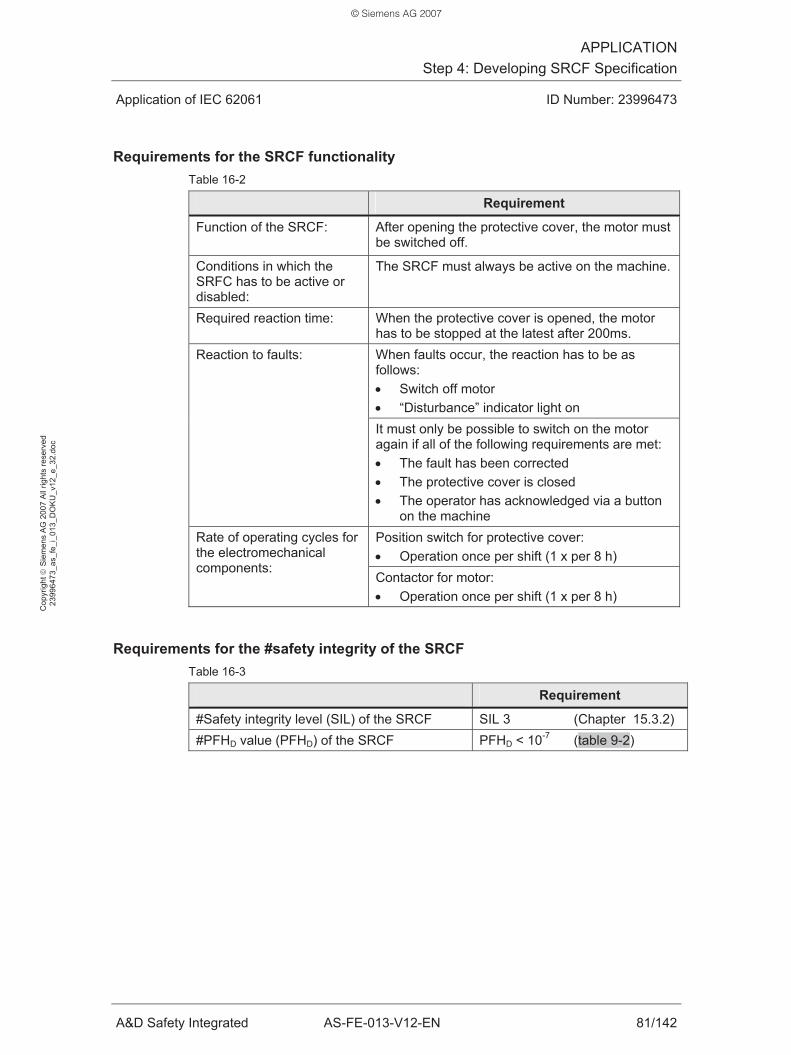
APPLICATIONStep 4: Developing SRCF Specification
Application of IEC 62061 ID Number: 23996473
A&D Safety Integrated AS-FE-013-V12-EN 81/142
Cop
yrig
ht ©
Sie
men
s A
G 2
007
All
right
s re
serv
ed
2399
6473
_as_
fe_i
_013
_DO
KU
_v12
_e_3
2.do
c
Requirements for the SRCF functionality Table 16-2
Requirement
Function of the SRCF:
After opening the protective cover, the motor must be switched off.
Conditions in which the SRFC has to be active or disabled:
The SRCF must always be active on the machine.
Required reaction time: When the protective cover is opened, the motor has to be stopped at the latest after 200ms. When faults occur, the reaction has to be as follows: • Switch off motor • “Disturbance” indicator light on
Reaction to faults:
It must only be possible to switch on the motor again if all of the following requirements are met: • The fault has been corrected • The protective cover is closed • The operator has acknowledged via a button
on the machine Position switch for protective cover: • Operation once per shift (1 x per 8 h)
Rate of operating cycles for the electromechanical components:
Contactor for motor: • Operation once per shift (1 x per 8 h)
Requirements for the #safety integrity of the SRCF Table 16-3
Requirement
#Safety integrity level (SIL) of the SRCF SIL 3 (Chapter 15.3.2) #PFHD value (PFHD) of the SRCF PFHD < 10-7 (table 9-2)
© Siemens AG 2007

APPLICATIONStep 5: Designing SRECS Architecture
Application of IEC 62061 ID Number: 23996473
A&D Safety Integrated AS-FE-013-V12-EN 82/142
Cop
yrig
ht ©
Sie
men
s A
G 2
007
All
right
s re
serv
ed
2399
6473
_as_
fe_i
_013
_DO
KU
_v12
_e_3
2.do
c
17 Step 5: Designing SRECS Architecture
After the specification of the #safety-related control function (SRCF), the architecture of the #safety system (SRECS) can now be designed.
17.1 Objective of the step
Each SRCF is intellectually divided into #function blocks in such a way that these #function blocks can be assigned to specific #subsystems of the SRECS. All designed #subsystems together then result in the required SRECS architecture.
Specific components are not yet selected in this step. This is done in step 6 (Realizing #Subsystems).
The step is based on the specification of the SRCF (step 4).
17.2 Procedure
To design the architecture of the SRECS, each SRCF is considered individually. The following steps are performed for each SRCF:
• Dividing SRCF into #function blocks
• Specifying requirements for #function blocks
• Assigning #function blocks to #subsystems
This procedure is illustrated in the figure below.
Figure 17-1
© Siemens AG 2007

APPLICATIONStep 5: Designing SRECS Architecture
Application of IEC 62061 ID Number: 23996473
A&D Safety Integrated AS-FE-013-V12-EN 83/142
Cop
yrig
ht ©
Sie
men
s A
G 2
007
All
right
s re
serv
ed
2399
6473
_as_
fe_i
_013
_DO
KU
_v12
_e_3
2.do
c
17.2.1 Dividing SRCF into #function blocks
The segmentation of the SRCF into #function blocks is performed so that the following statement applies:
• A failure of a #function block of the SRCF results in the failure of the SRCF (loss of the SRCF).
17.2.2 Specifying requirements for #function blocks
After the segmentation of the SRCF into #function blocks, the following requirements are specified for each #function block:
• Requirements for the SRCF functionality:
– What is the task of the #function block?
– Which input information does the #function block require?
– Which output information does the #function block generate?
• Requirements for the #safety integrity of the SRCF:
– Which #safety integrity level (SIL) has to be achieved by the #function blocks?
Remark on the #safety integrity:
The #safety integrity level (SIL) of the SRCF is “passed on” to the SRCF #function blocks. This means that the #safety integrity requirements for the #function blocks of the SRCF are identical to the #safety integrity requirements of the actual SRCF.
17.2.3 Assigning #function blocks to #subsystems
One #subsystem of the SRECS is assigned to each #function block of a SRCF. One #subsystem of a SRECS executes one #function block of the SRCF.
The #SIL claim limit (SILCL) of the designed #subsystems must be at least as large as the #safety integrity level (SIL) of the #function blocks.
© Siemens AG 2007
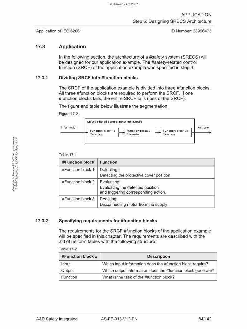
APPLICATIONStep 5: Designing SRECS Architecture
Application of IEC 62061 ID Number: 23996473
A&D Safety Integrated AS-FE-013-V12-EN 84/142
Cop
yrig
ht ©
Sie
men
s A
G 2
007
All
right
s re
serv
ed
2399
6473
_as_
fe_i
_013
_DO
KU
_v12
_e_3
2.do
c
17.3 Application
In the following section, the architecture of a #safety system (SRECS) will be designed for our application example. The #safety-related control function (SRCF) of the application example was specified in step 4.
17.3.1 Dividing SRCF into #function blocks
The SRCF of the application example is divided into three #function blocks. All three #function blocks are required to perform the SRCF. If one #function blocks fails, the entire SRCF fails (loss of the SRCF).
The figure and table below illustrate the segmentation. Figure 17-2
Table 17-1
#Function block Function
#Function block 1 Detecting: Detecting the protective cover position
#Function block 2 Evaluating: Evaluating the detected position and triggering corresponding action.
#Function block 3 Reacting: Disconnecting motor from the supply.
17.3.2 Specifying requirements for #function blocks
The requirements for the SRCF #function blocks of the application example will be specified in this chapter. The requirements are described with the aid of uniform tables with the following structure: Table 17-2
#Function block x Description
Input Which input information does the #function block require? Output Which output information does the #function block generate? Function What is the task of the #function block?
© Siemens AG 2007

APPLICATIONStep 5: Designing SRECS Architecture
Application of IEC 62061 ID Number: 23996473
A&D Safety Integrated AS-FE-013-V12-EN 85/142
Cop
yrig
ht ©
Sie
men
s A
G 2
007
All
right
s re
serv
ed
2399
6473
_as_
fe_i
_013
_DO
KU
_v12
_e_3
2.do
c
Functionality of #function block 1: Detecting Table 17-3
#Function block 1 Description
Input Position of the protective cover: “Open” or “closed” Output Information on the protective cover position:
• Protective cover is open • Protective cover is closed
Function For all modes of the machine: Detecting the protective cover position.
Functionality of #function block 2: Evaluating Table 17-4
#Function block 2 Description
Input Information on the protective cover position (output #function block 1)
Output Command to control the motor: • Disconnect motor from supply when protective cover
open Function For all modes of the machine:
Evaluation of the information on the protective cover position and corresponding control of the motor.
Functionality of #function block 3: Reacting Table 17-5
#Function block 3 Description
Input Command to control the motor (output of #function block 2)
Output --- Function For all modes of the machine:
• Disconnecting motor from the supply.
#Safety integrity of the #function blocks The “SRCF specification” defines that the SRCF has to comply with SIL 3. This means that each individual #function block must comply with at least SIL 3.
© Siemens AG 2007
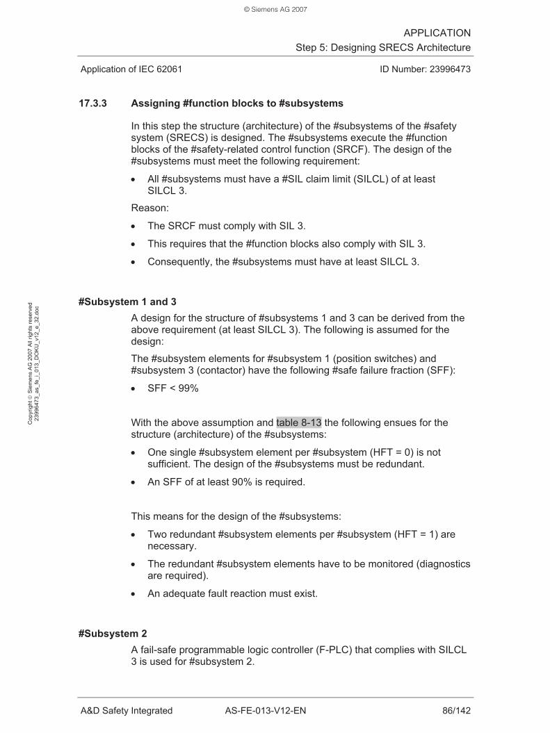
APPLICATIONStep 5: Designing SRECS Architecture
Application of IEC 62061 ID Number: 23996473
A&D Safety Integrated AS-FE-013-V12-EN 86/142
Cop
yrig
ht ©
Sie
men
s A
G 2
007
All
right
s re
serv
ed
2399
6473
_as_
fe_i
_013
_DO
KU
_v12
_e_3
2.do
c
17.3.3 Assigning #function blocks to #subsystems
In this step the structure (architecture) of the #subsystems of the #safety system (SRECS) is designed. The #subsystems execute the #function blocks of the #safety-related control function (SRCF). The design of the #subsystems must meet the following requirement:
• All #subsystems must have a #SIL claim limit (SILCL) of at least SILCL 3.
Reason:
• The SRCF must comply with SIL 3.
• This requires that the #function blocks also comply with SIL 3.
• Consequently, the #subsystems must have at least SILCL 3.
#Subsystem 1 and 3 A design for the structure of #subsystems 1 and 3 can be derived from the above requirement (at least SILCL 3). The following is assumed for the design:
The #subsystem elements for #subsystem 1 (position switches) and #subsystem 3 (contactor) have the following #safe failure fraction (SFF):
• SFF < 99%
With the above assumption and table 8-13 the following ensues for the structure (architecture) of the #subsystems:
• One single #subsystem element per #subsystem (HFT = 0) is not sufficient. The design of the #subsystems must be redundant.
• An SFF of at least 90% is required.
This means for the design of the #subsystems:
• Two redundant #subsystem elements per #subsystem (HFT = 1) are necessary.
• The redundant #subsystem elements have to be monitored (diagnostics are required).
• An adequate fault reaction must exist.
#Subsystem 2 A fail-safe programmable logic controller (F-PLC) that complies with SILCL 3 is used for #subsystem 2.
© Siemens AG 2007
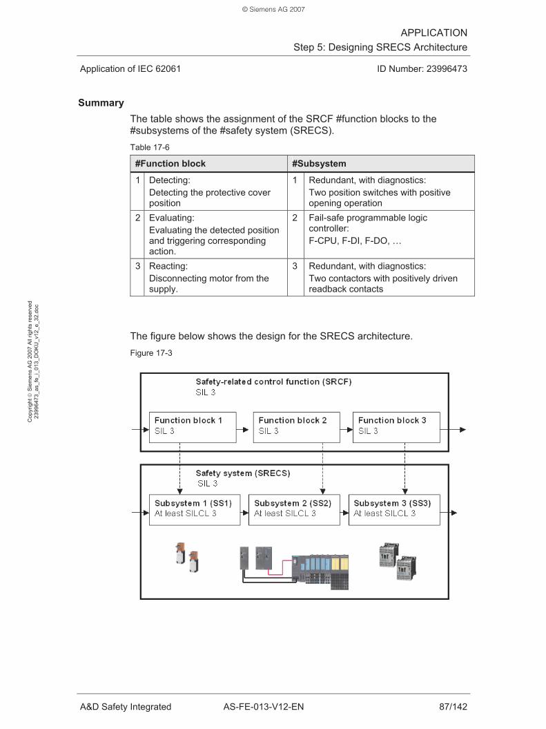
APPLICATIONStep 5: Designing SRECS Architecture
Application of IEC 62061 ID Number: 23996473
A&D Safety Integrated AS-FE-013-V12-EN 87/142
Cop
yrig
ht ©
Sie
men
s A
G 2
007
All
right
s re
serv
ed
2399
6473
_as_
fe_i
_013
_DO
KU
_v12
_e_3
2.do
c
Summary The table shows the assignment of the SRCF #function blocks to the #subsystems of the #safety system (SRECS). Table 17-6
#Function block #Subsystem
1 Detecting: Detecting the protective cover position
1 Redundant, with diagnostics: Two position switches with positive opening operation
2 Evaluating: Evaluating the detected position and triggering corresponding action.
2 Fail-safe programmable logic controller: F-CPU, F-DI, F-DO, …
3 Reacting: Disconnecting motor from the supply.
3 Redundant, with diagnostics: Two contactors with positively driven readback contacts
The figure below shows the design for the SRECS architecture. Figure 17-3
© Siemens AG 2007

APPLICATIONStep 6: Realizing #Subsystems
Application of IEC 62061 ID Number: 23996473
A&D Safety Integrated AS-FE-013-V12-EN 88/142
Cop
yrig
ht ©
Sie
men
s A
G 2
007
All
right
s re
serv
ed
2399
6473
_as_
fe_i
_013
_DO
KU
_v12
_e_3
2.do
c
18 Step 6: Realizing #Subsystems
After designing the architecture of the #safety system (SRECS), the #subsystems of the SRECS are now realized.
18.1 Structure of the step
In the document, step 6 is described in several chapters. The table below lists the individual chapters. Table 18-1
Chapter
Heading Contents
18 Step 6: Realizing #Subsystems Chapter structure, objective and procedure
19 Step 6 / Application: Overview Overview of the #subsystems 20 Step 6 / Application: #Subsystem 1 Application to #subsystem 1 21 Step 6 / Application: #Subsystem 2 Application to #subsystem 2 22 Step 6 / Application: #Subsystem 3 Application to #subsystem 3
18.2 Objective of the step
The #subsystems of the SRECS are realized in this step.
A SRECS must be realized in such a way that it meets all requirements according to the required SIL.
The objective is to sufficiently reduce the probability of faults which cause a dangerous state on the machine.
The following aspects have to be observed:
• Safety integrity of the hardware:
– #Architectural constraint
– #PFHD value (PFHD)
• #Systematic safety integrity:
– Avoidance of systematic faults
– Control of systematic faults
• Behavior of the SRECS when detecting a fault:
– Fault detection (diagnostics)
– Fault reaction
• Design and development of safety-related application software
© Siemens AG 2007

APPLICATIONStep 6: Realizing #Subsystems
Application of IEC 62061 ID Number: 23996473
A&D Safety Integrated AS-FE-013-V12-EN 89/142
Cop
yrig
ht ©
Sie
men
s A
G 2
007
All
right
s re
serv
ed
2399
6473
_as_
fe_i
_013
_DO
KU
_v12
_e_3
2.do
c
18.3 Procedure
To implement the requirements, the following considerations are made for each #subsystem:
• Consideration of the #architectural constraint (1)
• Consideration of the #PFHD value (PFHD) (2)
• Consideration of the diagnostics (3)
• Consideration of the #systematic safety integrity (4)
Considerations (1) and (2) concern the “safety integrity of the hardware”. Diagnostics (3) affect the “safety integrity of the hardware”.
The procedure for the above-mentioned considerations (1) to (4) will be described in the following chapters.
18.3.1 Consideration of the #architectural constraint
The structure (architecture) of the #subsystem must be realized in such a way that the #SIL claim limit (SILCL) of the #subsystem is at least equal to the #safety integrity level (SIL) of the #safety-related control function (SRCF).
For the determination of the SILCL: See chapter 8.4.
18.3.2 Consideration of the PFHD
The #PFHD value (PFHD) of the #safety-related control function (SRCF) is equal to the sum of the #PFHD values (PFHD) of the #subsystems.
The #subsystems must thus be realized in such a way that the PFHD value (PFHD) of the SRCF is not exceeded.
For the determination of the #PFHD value (PFHD): See chapter 9.4.
© Siemens AG 2007

APPLICATIONStep 6: Realizing #Subsystems
Application of IEC 62061 ID Number: 23996473
A&D Safety Integrated AS-FE-013-V12-EN 90/142
Cop
yrig
ht ©
Sie
men
s A
G 2
007
All
right
s re
serv
ed
2399
6473
_as_
fe_i
_013
_DO
KU
_v12
_e_3
2.do
c
18.3.3 Consideration of the diagnostics
Diagnostics are used to detect random and systematic faults in the hardware.
Examples of random faults:
• Break of the actuator of a position switch
• Contacts of a contactor will not open.
Examples of systematic faults:
• Short circuit, wire break (on lines)
Additional diagnostic functions enable to design a #subsystem in such a way that the #SIL claim limit (SILCL) improves:
• More diagnostics improve the #safe failure fraction (SFF) (improved fault detection)
• More diagnostics improve the #PFHD value (PFHD) (reduction of the PFHD)
The diagnostic functions do not have to be performed in the actual considered #subsystems. For example, diagnostics of #subsystem 1 can be performed in #subsystem 2.
18.3.4 Consideration of the #systematic safety integrity
In the #subsystems, measures have to be taken to achieve #systematic safety integrity (chapter 10).
#Systematic safety integrity is complied with if measures are taken which have the following effects:
• Avoidance of systematic faults
• Control of systematic faults
Diagnostics are one measure to control systematic faults (chapter 18.3.3).
© Siemens AG 2007

APPLICATIONStep 6 / Application: Overview of the #Subsystems
Application of IEC 62061 ID Number: 23996473
A&D Safety Integrated AS-FE-013-V12-EN 91/142
Cop
yrig
ht ©
Sie
men
s A
G 2
007
All
right
s re
serv
ed
2399
6473
_as_
fe_i
_013
_DO
KU
_v12
_e_3
2.do
c
19 Step 6 / Application: Overview of the #Subsystems
Objective and procedure of step 6 (Realizing #Subsystems) were described in the previous chapter. This chapter first provides an overview of the #subsystems to be realized. The subsequent chapters consider the individual #subsystems.
The architecture shown in the figure below is realized:
• #Safety system (SRECS) with three #subsystems
• #Subsystem 1 with two identical position switches
• #Subsystem 2 with “SIMATIC S7 Distributed Safety”
• #Subsystem 3 with two identical contactors Figure 19-1
The #subsystems have the following functions: Table 19-1
#Subsystem Function
1 Detecting: Detecting the protective cover position 2 Evaluating: Evaluating the detected position and triggering action. 3 Reacting: Disconnecting motor from the supply.
© Siemens AG 2007

APPLICATIONStep 6 / Application: Realizing #Subsystem 1
Application of IEC 62061 ID Number: 23996473
A&D Safety Integrated AS-FE-013-V12-EN 92/142
Cop
yrig
ht ©
Sie
men
s A
G 2
007
All
right
s re
serv
ed
2399
6473
_as_
fe_i
_013
_DO
KU
_v12
_e_3
2.do
c
20 Step 6 / Application: Realizing #Subsystem 1
This chapter describes the realization of #subsystem 1.
20.1 Design of #subsystem 1 (Detect function block)
Overview The design of #subsystem 1 is shown in figure 19-1.
The requirements for #subsystem 1 are listed in the table below (chapter 17): Table 20-1
#Subsystem 1 Requirement
Function Detecting the protective cover position #Safety integrity SILCL 3
Description of #subsystem 1 #Subsystem 1 consists of two identical #subsystem elements (position switches). Both position switches are wired to an F-DI. Both position switches are evaluated in the F-CPU.
F-DI and F-CPU are parts of #subsystem 2. #Subsystem 2 is realized with “SIMATIC S7 Distributed Safety”.
Note: A detailed description of the design is available in the Functional Examples (table 11.2). However, the information in this document is sufficient for the considerations concerning IEC 62061.
Description of #subsystem elements 1.1 and 1.2 The following position switch is used for both #subsystem elements: Table 20-2
Designation Type Order number Manufacturer
Position switch Metal-enclosed 3SE2120-6xx Actuator --- 3SX3197
Siemens (SIRIUS components)
The position switch has the following properties:
• Separate actuator
• Without tumbler
• Positively opening contacts
© Siemens AG 2007

APPLICATIONStep 6 / Application: Realizing #Subsystem 1
Application of IEC 62061 ID Number: 23996473
A&D Safety Integrated AS-FE-013-V12-EN 93/142
Cop
yrig
ht ©
Sie
men
s A
G 2
007
All
right
s re
serv
ed
2399
6473
_as_
fe_i
_013
_DO
KU
_v12
_e_3
2.do
c
Connecting the #subsystem elements of #subsystem 1 to #subsystem 2 The figure below shows the connection principle. The two position switches are connected to an F-DI. F-DI is a fail-safe digital input module of “SIMATIC S7 Distributed Safety”. Figure 20-1
Connection of the F-DI:
• One channel per position switch
• Power supply of the position switches via the F-DI
Parameterization of the F-DI:
• 1-channel sensor interconnection
• F monitoring time of the module
• Short circuit test, cyclically per channel
Diagnostics of #subsystem 1 The following diagnostics have been realized for #subsystem 1: Table 20-3
Diagnostics of #subsystem 1 Diagnostics location
If, after a monitoring time has elapsed, both position switch values are different, a fault has occurred. Example of a fault: Position switch actuator broken off or worn.
#Subsystem 2: F-CPU
© Siemens AG 2007

APPLICATIONStep 6 / Application: Realizing #Subsystem 1
Application of IEC 62061 ID Number: 23996473
A&D Safety Integrated AS-FE-013-V12-EN 94/142
Cop
yrig
ht ©
Sie
men
s A
G 2
007
All
right
s re
serv
ed
2399
6473
_as_
fe_i
_013
_DO
KU
_v12
_e_3
2.do
c
20.2 Consideration of the #architectural constraint
Procedure The #SIL claim limit (SILCL) of #subsystem 1 is determined in this chapter. To do this, first the hardware fault tolerance (HFT) and the #safe failure fraction (SFF) are determined. Subsequently, the SILCL is determined (chapter 8.7).
HFT determination A failure of a #subsystem element does not cause the loss of the #safety-related control function (SRCF). Consequently, the #fault tolerance of #subsystem 1 is one: HFT = 1
SFF determination SFF refers to the #subsystem. For #subsystems with several identical #subsystem elements, it is sufficient to consider one #subsystem element by itself. The analysis of the #subsystem element (position switch) yields the following failures and failure modes: Table 20-4
Failure rate type
Fraction of this failure mode
Failure Failure mode
Failure detected by diagnostics
λS λD λDU Value Source
Contact does not open
Dangerous Yes x 20%
Contact does not close
Safe --- x 80%
Manufacturer of the position
switch
Note: Wire break and short circuit are not considered here since they are systematic faults.
Since all dangerous failures are detected by diagnostics, the following applies:
• λDutotal = Σ λDU = 0
This results in the following SFF (table 8-6):
• SFF = (λtotal - λDUtotal) / λtotal = λtotal / λtotal = 1
SILCL determination The SILCL is determined from HFT and SFF (table 8-13):
• SILCL 3
© Siemens AG 2007

APPLICATIONStep 6 / Application: Realizing #Subsystem 1
Application of IEC 62061 ID Number: 23996473
A&D Safety Integrated AS-FE-013-V12-EN 95/142
Cop
yrig
ht ©
Sie
men
s A
G 2
007
All
right
s re
serv
ed
2399
6473
_as_
fe_i
_013
_DO
KU
_v12
_e_3
2.do
c
20.3 Consideration of the PFHD
The PFHD of #subsystem 1 is determined in this chapter.
IEC 62061 provides the formulae for calculating the #PFHD value (PFHD) for four basic subsystem architectures.
#Subsystem 1 complies with the characteristics of basic subsystem architecture D:
• Single fault tolerance with diagnostic functions
The reason is described in the following table. Table 20-5
Characteristic of “D” Realization of #subsystem 1
Single fault tolerance A failure of a #subsystem element (position switch) does not cause the loss of the #safety-related control function (SRCF).
Diagnostic functions Faults in #subsystem 1 are detected in #subsystem 2 by diagnostics. This is done by comparing the states of the two position switches in the F-CPU.
To calculate the PFHD, parameters of the #subsystem element and parameters of the #subsystem are used. The figure below shows the assignment of the parameters. Figure 20-2
© Siemens AG 2007

APPLICATIONStep 6 / Application: Realizing #Subsystem 1
Application of IEC 62061 ID Number: 23996473
A&D Safety Integrated AS-FE-013-V12-EN 96/142
Cop
yrig
ht ©
Sie
men
s A
G 2
007
All
right
s re
serv
ed
2399
6473
_as_
fe_i
_013
_DO
KU
_v12
_e_3
2.do
c
20.3.1 PFHD calculation
Note: For explanations of the calculation of the PFHD value (PFHD), please refer to chapter 9.8.
Information on the #subsystem element of #subsystem 1 Table 20-6
#Subsystem element
Type SIRIUS position switch Technical data Chapter 27.5
Dangerous failure rate of the #subsystem element Table 20-7
Parameter Meaning Value
B10 B10 value position switch 1 * 106 C Number of position switch operations (1 x per
shift, i.e. every 8 hours) 0.125 / h
Dangerous failure fraction
Dangerous failure fraction of the position switch
0.2
Table 20-8
Result
Dangerous failure rate of the #subsystem element (λDe) 2.5 * 10-9 / h
#PFHD value (PFHD) of the #subsystem Table 20-9
Parameter Meaning Value
λDe Dangerous failure rate of the #subsystem element (from table 20-7)
2.5 * 10-9 / h
β (CCF factor)
Susceptibility to common cause failures 0.1
T1 Lifetime of the position switch 87600 h T2 Diagnostic test interval (when opening the
protective cover, a defective position switch is detected in the F-CPU. An opening is performed once per shift, i.e. every 8 hours)
8 h
DC #Diagnostic coverage (DC) position switches (From chapter 20.3.2)
1
Table 20-10
Result
#PFHD value (PFHD) of the #subsystem 2.5 * 10-10
© Siemens AG 2007
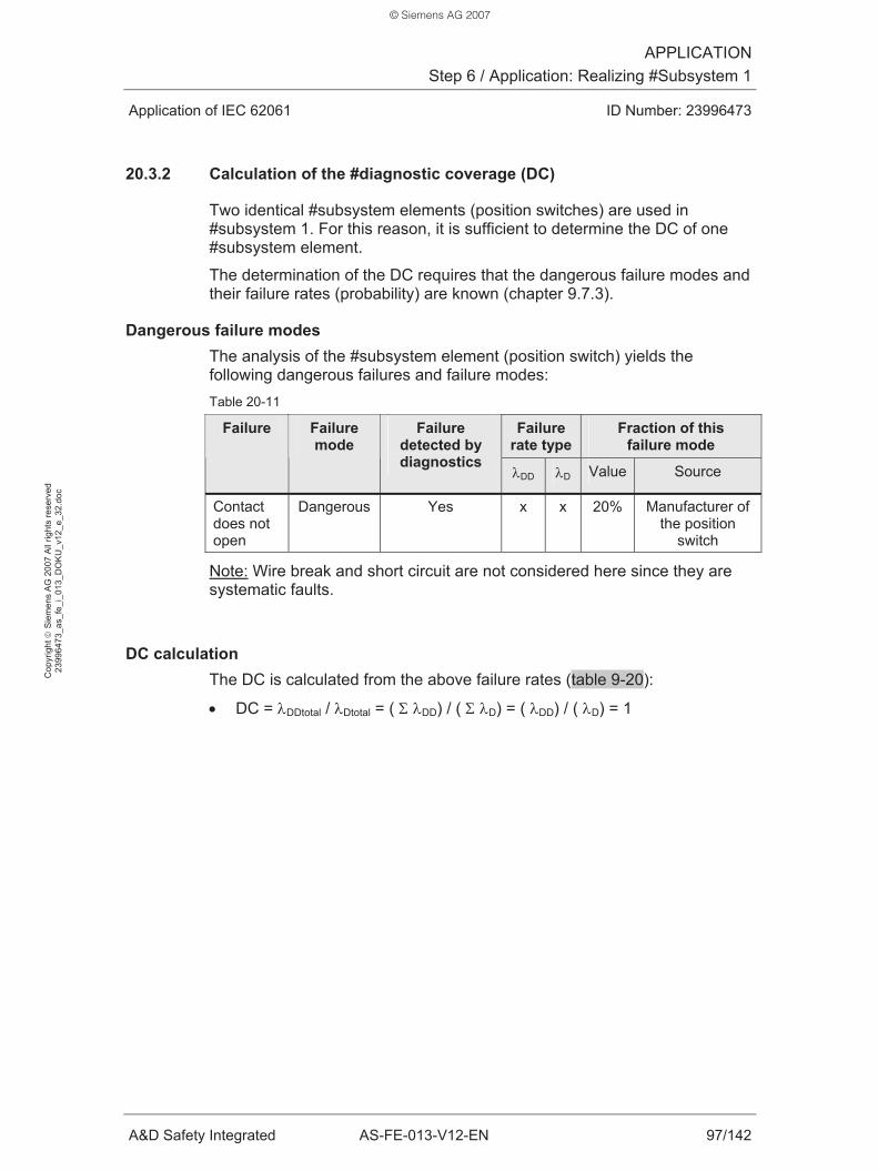
APPLICATIONStep 6 / Application: Realizing #Subsystem 1
Application of IEC 62061 ID Number: 23996473
A&D Safety Integrated AS-FE-013-V12-EN 97/142
Cop
yrig
ht ©
Sie
men
s A
G 2
007
All
right
s re
serv
ed
2399
6473
_as_
fe_i
_013
_DO
KU
_v12
_e_3
2.do
c
20.3.2 Calculation of the #diagnostic coverage (DC)
Two identical #subsystem elements (position switches) are used in #subsystem 1. For this reason, it is sufficient to determine the DC of one #subsystem element.
The determination of the DC requires that the dangerous failure modes and their failure rates (probability) are known (chapter 9.7.3).
Dangerous failure modes The analysis of the #subsystem element (position switch) yields the following dangerous failures and failure modes: Table 20-11
Failure rate type
Fraction of this failure mode
Failure Failure mode
Failure detected by diagnostics
λDD λD Value Source
Contact does not open
Dangerous Yes x x 20% Manufacturer of the position
switch
Note: Wire break and short circuit are not considered here since they are systematic faults.
DC calculation The DC is calculated from the above failure rates (table 9-20):
• DC = λDDtotal / λDtotal = ( Σ λDD) / ( Σ λD) = ( λDD) / ( λD) = 1
© Siemens AG 2007

APPLICATIONStep 6 / Application: Realizing #Subsystem 1
Application of IEC 62061 ID Number: 23996473
A&D Safety Integrated AS-FE-013-V12-EN 98/142
Cop
yrig
ht ©
Sie
men
s A
G 2
007
All
right
s re
serv
ed
2399
6473
_as_
fe_i
_013
_DO
KU
_v12
_e_3
2.do
c
20.4 Consideration of the diagnostics
The diagnostic functions realized in #subsystem 1 are summarized in the table below. Table 20-12
Diagnostic function Diagnostics location
Fault reaction
Evaluation of the two position switches in the F-CPU. If different states are detected, a fault has occurred.
#Subsystem 2: F-CPU
Disconnecting the motor from the supply.
20.5 Consideration of the #systematic safety integrity
The requirements for the #systematic safety integrity equally apply to all #subsystems. Also #subsystem 1 must meet these requirements.
Examples of measures to avoid and control systematic faults are listed in chapter 10.
20.6 Summary
The realized #subsystem 1 has the following properties: Table 20-13
SILCL PFHD
#Subsystem 1 3 2.5 * 10-10
© Siemens AG 2007

APPLICATIONStep 6 / Application: Realizing #Subsystem 2
Application of IEC 62061 ID Number: 23996473
A&D Safety Integrated AS-FE-013-V12-EN 99/142
Cop
yrig
ht ©
Sie
men
s A
G 2
007
All
right
s re
serv
ed
2399
6473
_as_
fe_i
_013
_DO
KU
_v12
_e_3
2.do
c
21 Step 6 / Application: Realizing #Subsystem 2
This chapter describes the realization of #subsystem 2.
21.1 Design of #subsystem 2 (Evaluate function block)
Overview The design of #subsystem 2 is shown in figure 19-1.
The requirements for #subsystem 2 are listed in the table below (chapter 17): Table 21-1
#Subsystem 2 Requirement
Function Evaluating the detected position and triggering associated action.
#Safety integrity SILCL 3
Description of #subsystem 2 #Subsystem 2 is a finished #subsystem. #Subsystem 2 is realized with “SIMATIC S7 Distributed Safety”.
“SIMATIC S7 Distributed Safety” is certified according to IEC 61508.
The following “SIMATIC Distributed Safety” components are used in #subsystem 2:
• Fail-safe CPU: F-CPU
• Fail-safe I/O modules: F-DI and F-DO of the ET200S
• Software for programming and configuring: S7 Distributed Safety
The design of the #subsystem is distributed. The F-CPU communicates with F-DI and F-DO via PROFIsafe. PROFIsafe is a profile which ensures fail-safe communication.
Note: A detailed description of the design is available in the Functional Examples (table 11-2). However, the information in this document is sufficient for the considerations concerning IEC 62061.
Description of F-DI See #subsystem 1: Chapter 20.1.
Description of F-DO See #subsystem 3: Chapter 22.1.
© Siemens AG 2007

APPLICATIONStep 6 / Application: Realizing #Subsystem 2
Application of IEC 62061 ID Number: 23996473
A&D Safety Integrated AS-FE-013-V12-EN 100/142
Cop
yrig
ht ©
Sie
men
s A
G 2
007
All
right
s re
serv
ed
2399
6473
_as_
fe_i
_013
_DO
KU
_v12
_e_3
2.do
c
Description of F-CPU The F-CPU processes the user program. The user program consists of the following parts:
• Standard program (S program)
• Fail-safe program (F program)
The safety-related tasks are performed in the F program, the non-safety-related tasks are executed in the S program.
Tasks of the F program:
The position switches of #subsystem 1 are detected in the F program:
• “0” means: Switch or protective cover open.
• “1” means: Switch or protective cover closed.
If the “0” state of at least one position switch is read, the contactors of #subsystem 3 are switched off. This disconnects the motor from the supply.
The motor must only be switched on again when the two following requirements are met:
• The operator has acknowledged.
• Both position switches supply “1” (protective cover closed).
To evaluate the position switches of #subsystem 1 and the readback signals of the contactors of #subsystem 3, certified F blocks from the “S7 Distributed Safety” library are used.
Communication with the I/Os (DI, F-DI, F-DO):
The F-CPU communicates with the ET200S I/O system via PROFIBUS.
Description of DI DI is a standard input module of SIMATIC. The DI is used for the diagnostics of #subsystem 3 (readback of the contactors).
© Siemens AG 2007

APPLICATIONStep 6 / Application: Realizing #Subsystem 2
Application of IEC 62061 ID Number: 23996473
A&D Safety Integrated AS-FE-013-V12-EN 101/142
Cop
yrig
ht ©
Sie
men
s A
G 2
007
All
right
s re
serv
ed
2399
6473
_as_
fe_i
_013
_DO
KU
_v12
_e_3
2.do
c
21.2 Consideration of the #architectural constraint
#Subsystem 2 is a finished #subsystem which is purchased from SIEMENS.
According to the information provided by Siemens, “SIMATIC S7 Distributed Safety” has a maximum #SIL claim limit (SILCL) of 3 (chapter 27.4).
In this application example, #subsystem 2 achieves the following #SIL claim limit (SILCL):
• SILCL 3
21.3 Consideration of the PFHD
“SIMATIC S7 Distributed Safety” is used for #subsystem 2. The formula below is used to calculate the #PFHD value (PFHD): Table 21-2
PFHD of #subsystem 2
PFHD (#subsystem 2) = PFHD (F-CPU) + PFHD (F I/O) + PTE (F Communication)
The following boundary conditions apply to the calculations:
• The #proof test interval is 10 years.
• F-CPU and F I/O are operated in “safety mode”.
• The contribution of the digital communication between the #subsystems to the PFHD of a SRCF is added to #subsystem 2.
Information required for the calculation (chapter 27.4): Table 21-3
Parameter Value Component Source
PFHD (F-CPU) 5.43 * 10-10 CPU 315F Siemens
1 * 10-10 F-DI Siemens PFHD (F I/O) 1 * 10-10 F-DO Siemens
PTE (F Communication) 1 * 10-9 F Communication Siemens
This results in the PFHD for #subsystem 2: Table 21-4
Result
#PFHD value (PFHD) of the #subsystem 1.743 * 10-9
© Siemens AG 2007

APPLICATIONStep 6 / Application: Realizing #Subsystem 2
Application of IEC 62061 ID Number: 23996473
A&D Safety Integrated AS-FE-013-V12-EN 102/142
Cop
yrig
ht ©
Sie
men
s A
G 2
007
All
right
s re
serv
ed
2399
6473
_as_
fe_i
_013
_DO
KU
_v12
_e_3
2.do
c
21.4 Consideration of the diagnostics
A consideration is not required since #subsystem 2 (SIMATIC S7 Distributed Safety) is certified according to IEC 61508.
21.5 Consideration of the #systematic safety integrity
A consideration is not required since #subsystem 2 (SIMATIC S7 Distributed Safety) is certified according to IEC 61508.
If the user complies with the installation instructions and manuals, #systematic safety integrity is ensured.
21.6 Summary
The realized #subsystem 2 has the following properties: Table 21-5
SILCL PFHD
#Subsystem 2 3 1.743 * 10-9
© Siemens AG 2007

APPLICATIONStep 6 / Application: Realizing #Subsystem 3
Application of IEC 62061 ID Number: 23996473
A&D Safety Integrated AS-FE-013-V12-EN 103/142
Cop
yrig
ht ©
Sie
men
s A
G 2
007
All
right
s re
serv
ed
2399
6473
_as_
fe_i
_013
_DO
KU
_v12
_e_3
2.do
c
22 Step 6 / Application: Realizing #Subsystem 3
This chapter describes the realization of #subsystem 3.
22.1 Design of #subsystem 3 (React function block)
Overview The design of #subsystem 3 is shown in figure 19-1.
The requirements for #subsystem 3 are listed in the table below (chapter 17): Table 22-1
#Subsystem 3 Requirement
Function Disconnecting motor from the supply. #Safety integrity SILCL 3
Description of #subsystem 3 #Subsystem 3 consists of two identical #subsystem elements (contactors). The load contacts of both contactors are connected in series. This ensures that the motor is connected to or disconnected from the supply.
The coils of both contactors are wired to an F-DO. Both coils are simultaneously switched via one single channel of the F-DO.
The readback contacts of both contactors are separately wired to a DI (standard I/O module).
The control of the coils and the evaluation of the readback signals are performed in the F program (fail-safe program) of the F-CPU.
F-DO and F-CPU are parts of #subsystem 2. #Subsystem 2 is realized with “SIMATIC S7 Distributed Safety”.
Note: A detailed description of the design is available in the Functional Examples (table 11-2). However, the information in this document is sufficient for the considerations concerning IEC 62061.
Description of #subsystem elements 3.1 and 3.2 The following contactor is used for both #subsystem elements: Table 22-2
Designation Type Order number Manufacturer
Contactor AC-3, 3KW/400V, 1NC, 24VDC
3RT1015-2BB42 Siemens (SIRIUS components)
The contactor has the following properties:
• Positively driven and positively opening readback contacts
© Siemens AG 2007

APPLICATIONStep 6 / Application: Realizing #Subsystem 3
Application of IEC 62061 ID Number: 23996473
A&D Safety Integrated AS-FE-013-V12-EN 104/142
Cop
yrig
ht ©
Sie
men
s A
G 2
007
All
right
s re
serv
ed
2399
6473
_as_
fe_i
_013
_DO
KU
_v12
_e_3
2.do
c
Connecting the #subsystem elements of #subsystem 3 to #subsystem 2 The figure below shows the connection principle. The contactors are connected to an F-DO. F-DO is a fail-safe digital output module of “SIMATIC S7 Distributed Safety”. Figure 22-1
Connection of the F-DO:
• One single output channel of the F-DO simultaneously switches both contactors K1 and K2
Parameterization of the F-DO:
• No peculiarities
Connection of the DI:
• The readback signals of the two contactors K1 and K2 are read in separately.
Diagnostics of #subsystem 3 The following diagnostics have been realized for #subsystem 3: Table 22-3
Diagnostics of #subsystem 3 Diagnostics location
If the readback signals do not correspond to the switching status of the contactors, a fault has occurred. Example of a fault: Load contacts of the contactor will not open.
#Subsystem 2: F-CPU
© Siemens AG 2007
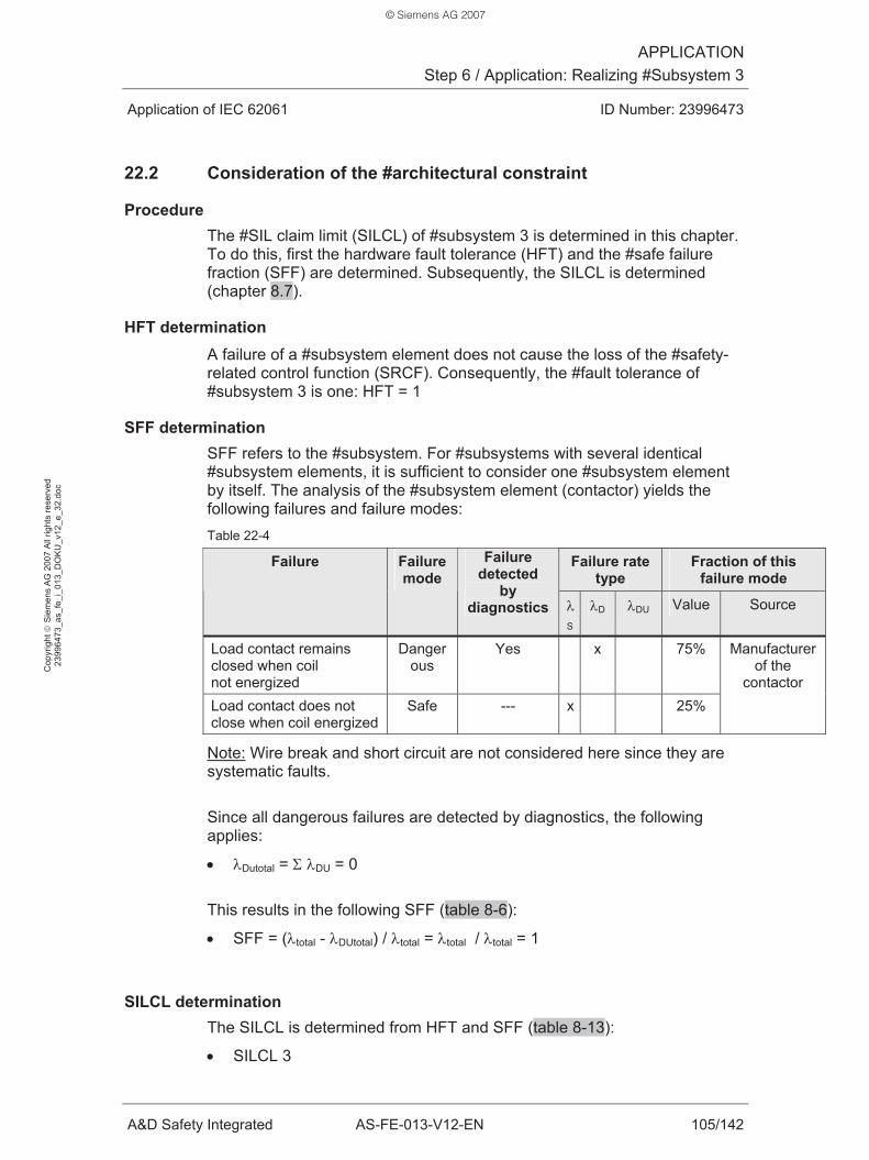
APPLICATIONStep 6 / Application: Realizing #Subsystem 3
Application of IEC 62061 ID Number: 23996473
A&D Safety Integrated AS-FE-013-V12-EN 105/142
Cop
yrig
ht ©
Sie
men
s A
G 2
007
All
right
s re
serv
ed
2399
6473
_as_
fe_i
_013
_DO
KU
_v12
_e_3
2.do
c
22.2 Consideration of the #architectural constraint
Procedure The #SIL claim limit (SILCL) of #subsystem 3 is determined in this chapter. To do this, first the hardware fault tolerance (HFT) and the #safe failure fraction (SFF) are determined. Subsequently, the SILCL is determined (chapter 8.7).
HFT determination A failure of a #subsystem element does not cause the loss of the #safety-related control function (SRCF). Consequently, the #fault tolerance of #subsystem 3 is one: HFT = 1
SFF determination SFF refers to the #subsystem. For #subsystems with several identical #subsystem elements, it is sufficient to consider one #subsystem element by itself. The analysis of the #subsystem element (contactor) yields the following failures and failure modes: Table 22-4
Failure rate type
Fraction of this failure mode
Failure Failure mode
Failure detected
by diagnostics λ
S
λD λDU Value Source
Load contact remains closed when coil not energized
Dangerous
Yes x 75%
Load contact does not close when coil energized
Safe --- x 25%
Manufacturer of the
contactor
Note: Wire break and short circuit are not considered here since they are systematic faults.
Since all dangerous failures are detected by diagnostics, the following applies:
• λDutotal = Σ λDU = 0
This results in the following SFF (table 8-6):
• SFF = (λtotal - λDUtotal) / λtotal = λtotal / λtotal = 1
SILCL determination The SILCL is determined from HFT and SFF (table 8-13):
• SILCL 3
© Siemens AG 2007

APPLICATIONStep 6 / Application: Realizing #Subsystem 3
Application of IEC 62061 ID Number: 23996473
A&D Safety Integrated AS-FE-013-V12-EN 106/142
Cop
yrig
ht ©
Sie
men
s A
G 2
007
All
right
s re
serv
ed
2399
6473
_as_
fe_i
_013
_DO
KU
_v12
_e_3
2.do
c
22.3 Consideration of the PFHD
The PFHD of #subsystem 3 is determined in this chapter.
IEC 62061 provides the formulae for calculating the PFHD for four basic subsystem architectures.
#Subsystem 3 complies with the characteristics of basic subsystem architecture D:
• Single fault tolerance with diagnostic functions
The reason is described in the following table: Table 22-5
Characteristic of “D” Realization of #subsystem 3
Single fault tolerance A failure of a #subsystem element (contactor) does not cause the loss of the #safety-related control function (SRCF).
Diagnostic functions Faults in #subsystem 3 are detected in #subsystem 2 by diagnostics. This is done by evaluating the readback signals.
To calculate the PFHD, parameters of the #subsystem element and parameters of the #subsystem are used. The figure below shows the assignment of the parameters. Figure 22-2
© Siemens AG 2007

APPLICATIONStep 6 / Application: Realizing #Subsystem 3
Application of IEC 62061 ID Number: 23996473
A&D Safety Integrated AS-FE-013-V12-EN 107/142
Cop
yrig
ht ©
Sie
men
s A
G 2
007
All
right
s re
serv
ed
2399
6473
_as_
fe_i
_013
_DO
KU
_v12
_e_3
2.do
c
22.3.1 PFHD calculation
Note: For explanations of the calculation of the PFHD value (PFHD), please refer to chapter 9.8.
Information on the #subsystem element of #subsystem 3 Table 22-6
#Subsystem element
Type SIRIUS contactor Technical data Chapter 27.5
Dangerous failure rate of the #subsystem element Table 22-7
Parameter Meaning Value
B10 B10 value contactor 1 * 106 C Number of contactor operations (1 x per shift,
i.e. every 8 hours) 0.125 / h
Dangerous failure fraction
Dangerous failure fraction of the contactor 0.75
Table 22-8
Result
Dangerous failure rate of the #subsystem element (λDe) 9.4 * 10-9 / h
#PFHD value (PFHD) of the #subsystem Table 22-9
Parameter Meaning Value
λDe Dangerous failure rate of the #subsystem element (from table 20-7)
9.4 * 10-9 / h
β (CCF factor)
Susceptibility to common cause failures 0.1
T1 Lifetime of the contactor 87600 h T2 Diagnostic test interval (when disconnecting the
motor from the supply, a defective contactor is detected in the F-CPU. Switching off is performed once per shift, i.e. every 8 hours)
8 h
DC #Diagnostic coverage (DC) of the contactor (from chapter 22.3.2)
1
Table 22-10
Result
#PFHD value (PFHD) of the #subsystem 9.4 * 10-10
© Siemens AG 2007

APPLICATIONStep 6 / Application: Realizing #Subsystem 3
Application of IEC 62061 ID Number: 23996473
A&D Safety Integrated AS-FE-013-V12-EN 108/142
Cop
yrig
ht ©
Sie
men
s A
G 2
007
All
right
s re
serv
ed
2399
6473
_as_
fe_i
_013
_DO
KU
_v12
_e_3
2.do
c
22.3.2 Calculation of the #diagnostic coverage (DC)
Two identical #subsystem elements (contactors) are used in #subsystem 3. For this reason, it is sufficient to determine the DC of one #subsystem element.
The determination of the DC requires that the dangerous failure modes and their failure rates (probability) are known (chapter 9.7.3).
Dangerous failure modes The analysis of the #subsystem element (contactor) yields the following dangerous failures and failure modes: Table 22-11
Failure rate type
Fraction of this failure mode
Failure Failure mode
Failure detected
by diagnostics λDD λD Value Source
Load contact remains closed when coil not energized
Dangerous Yes x x 75% Manufacturer of the
contactor
Note: Wire break and short circuit are not considered here since they are systematic faults.
DC calculation The DC is calculated from the above failure rates (table 9-20):
• DC = λDDtotal / λDtotal = ( Σ λDD) / ( Σ λD) = ( λDD) / ( λD) = 1
© Siemens AG 2007

APPLICATIONStep 6 / Application: Realizing #Subsystem 3
Application of IEC 62061 ID Number: 23996473
A&D Safety Integrated AS-FE-013-V12-EN 109/142
Cop
yrig
ht ©
Sie
men
s A
G 2
007
All
right
s re
serv
ed
2399
6473
_as_
fe_i
_013
_DO
KU
_v12
_e_3
2.do
c
22.4 Consideration of the diagnostics
The diagnostic functions realized in #subsystem 3 are summarized in the table below. Table 22-12
Diagnostic function Diagnostics location
Reaction to faults
Evaluation of the readback signals of the two contactors in the F-CPU. If the statuses do not correspond to the switching statuses of the contactors, a fault has occurred.
#Subsystem 2: F-CPU
Disconnecting the motor from the supply.
22.5 Consideration of the #systematic safety integrity
The requirements for the #systematic safety integrity equally apply to all #subsystems. Also #subsystem 3 must meet these requirements.
Examples of measures to avoid and control systematic faults are listed in chapter 10.
22.6 Summary
The realized #subsystem 3 has the following properties: Table 22-13
SILCL PFHD
#Subsystem 3 3 9.4 * 10-10
© Siemens AG 2007

APPLICATIONStep 7: Determining SIL Achieved by SRECS
Application of IEC 62061 ID Number: 23996473
A&D Safety Integrated AS-FE-013-V12-EN 110/142
Cop
yrig
ht ©
Sie
men
s A
G 2
007
All
right
s re
serv
ed
2399
6473
_as_
fe_i
_013
_DO
KU
_v12
_e_3
2.do
c
23 Step 7: Determining SIL Achieved by SRECS
23.1 Objective of the step
In this step it is checked whether the required #safety integrity level (SIL) is achieved for each #safety-related control function (SRCF) with the realized #safety system (SRECS).
23.2 Procedure
To ensure that the SIL required for the SRCF is achieved, the following requirements have to be met for each individual SRCF:
Requirements, clearly graded according to SIL:
• The #SIL claim limit (SILCL) of each SRCF #subsystem must at least correspond to the #safety integrity level (SIL) of the SRCF.
• The sum of the #PFHD values (PFHD) of all SRCF #subsystems must not exceed the #PFHD value (PFHD) specified by the #safety integrity level (SIL) of the SRCF.
• If a #subsystem is used by different SRCFs, the #SIL claim limit (SILCL) of the #subsystem must comply with the highest #safety integrity level (SIL) of the SRCF.
Requirement, slightly graded according to SIL:
• #Systematic safety integrity must be complied with.
To review the requirements clearly depending on the SIL, the following steps are performed:
• Determination of the minimum SILCL of all #subsystems of the SRCF
• Determination of the PFHD of the SRCF
• Derivation of the SIL which is achieved with the SRECS
© Siemens AG 2007

APPLICATIONStep 7: Determining SIL Achieved by SRECS
Application of IEC 62061 ID Number: 23996473
A&D Safety Integrated AS-FE-013-V12-EN 111/142
Cop
yrig
ht ©
Sie
men
s A
G 2
007
All
right
s re
serv
ed
2399
6473
_as_
fe_i
_013
_DO
KU
_v12
_e_3
2.do
c
23.2.1 Determination of the minimum SILCL of all #subsystems of the SRCF
The lowest #SIL claim limit (SILCL) of all #subsystems of the #safety-related control function (SRCF) is determined:
• SILCL_Min = Minimum { SILCL (SS1), …, SILCL(SSn) }
23.2.2 Determination of the PFHD of the SRCF
The #PFHD value (PFHD) of a SRCF is calculated as follows (chapter 9.3):
• PFHD (SRCF) = PFHD (SS1) + …+ PFHD (SSn) + PTE (communication)
The more #subsystems are required for the performance of a SRCF, the higher the probability that one of these #subsystems fails. Thus also the probability of a SRCF failure is higher. This aspect is considered via the addition.
23.2.3 Derivation of the SIL which is achieved with the SRECS
The required #safety integrity level (SIL) for the #safety-related control function (SRCF) is achieved when the two requirements listed below are met. Table 23-1
Requirement Description
SILCL_Min ≥ SIL
The SILCL of each #subsystem of the SRCF must at least correspond to the SIL of the SRCF.
PFHD (SRCF) ≤ PFHD (SIL)
The sum of the #PFHD values (PFHD) must not be larger than the #PFHD value (PFHD) defined by the SIL. PFHD (SIL) is determined from table 9-2.
© Siemens AG 2007

APPLICATIONStep 7: Determining SIL Achieved by SRECS
Application of IEC 62061 ID Number: 23996473
A&D Safety Integrated AS-FE-013-V12-EN 112/142
Cop
yrig
ht ©
Sie
men
s A
G 2
007
All
right
s re
serv
ed
2399
6473
_as_
fe_i
_013
_DO
KU
_v12
_e_3
2.do
c
23.2.4 Measures to achieve the required SIL
If the required SIL for a SRCF is not achieved, the design of the #subsystem has to be touched up.
Depending on whether either SILCL or PFHD has not been achieved, different options exist:
Examples for improving the #SIL claim limit (SILCL):
• Improvement by redundancy in the #subsystems
• Improvement by diagnostics: Converting dangerous undetected failures to dangerous detected failures.
Examples of improving the #PFHD value (PFHD):
• Using #subsystems or #subsystem elements with an improved #PFHD value (PFHD).
• Increasing #diagnostic coverage (DC) by more diagnostics
• Reducing CCF factor by appropriate measures (example: Selection of different components)
23.3 Application
The risk analysis and the risk assessment for our example machine has yielded the following result:
• A SRCF with SIL 3 is necessary.
A #safety system (SRECS) consisting of three #subsystems was realized for this SRCF. The properties are summarized in the table below. Table 23-2
#Subsystem SILCL PFHD
#Subsystem 1 (SS1) 3 2.5 * 10-10
#Subsystem 2 (SS2) 3 1.743 * 10-9
#Subsystem 3 (SS3) 3 9.4 * 10-10
23.3.1 Determination of the minimum SILCL of all #subsystems of the SRCF
Minimum #SIL claim limit (SILCL) of all #subsystems:
• SILCL_Min = 3
© Siemens AG 2007

APPLICATIONStep 7: Determining SIL Achieved by SRECS
Application of IEC 62061 ID Number: 23996473
A&D Safety Integrated AS-FE-013-V12-EN 113/142
Cop
yrig
ht ©
Sie
men
s A
G 2
007
All
right
s re
serv
ed
2399
6473
_as_
fe_i
_013
_DO
KU
_v12
_e_3
2.do
c
23.3.2 Determination of the PFHD of the SRCF
The #PFHD value (PFHD) of the SRCF is calculated as follows:
• PFHD (SRCF) = PFHD (SS1) + PFHD (SS2) + PFHD (SS3) = 2.933 * 10-9
The chart below illustrates the order of magnitude of the #PFHD values (PFHD). Figure 23-1
23.3.3 Derivation of the SIL which is achieved with the SRECS
#PFHD value (PFHD) for SIL 3:
• SIL 3 PFHD (SIL) < 10-7 (from table 9-2)
Requirements review: Table 23-3
Requirement Application Met?
SILCL_Min ≥ SIL 3 ≥ 3 Yes
PFHD (SRCF) ≤ PFHD (SIL) 0.02933 * 10-7 ≤ 1 * 10-7 Yes
Result:
• SIL 3 is achieved with the #safety system (SRECS)!
© Siemens AG 2007

APPLICATIONSteps 8 to 12: Implementing SRECS
Application of IEC 62061 ID Number: 23996473
A&D Safety Integrated AS-FE-013-V12-EN 114/142
Cop
yrig
ht ©
Sie
men
s A
G 2
007
All
right
s re
serv
ed
2399
6473
_as_
fe_i
_013
_DO
KU
_v12
_e_3
2.do
c
24 Steps 8 to 12: Implementing SRECS
In step 7 it was checked whether the previously designed #safety system (SRECS) actually complies with the required properties. If this is the case, the SRECS can now be implemented.
This chapter provides a brief description of the steps required for the implementation. IEC 62061 also includes requirements for these steps which are to be met by appropriate measures.
Step 8: Implementing hardware The #safety system (SRECS) must be implemented in accordance with the documented design of the SRECS.
Step 9: Specifying software In our application, application software is required for the #safety-related control function (SRCF). The application software is executed by the F-CPU of #subsystem 2.
According to IEC 62061, a specification has to be developed for this application software.
Step 10: Designing and developing software The application software specified in step 9 has to be realized according to the requirements of IEC 62061. These requirements are based on IEC 61508.
Step 11: Integrating and testing The integration of the #safety system (SRECS) must be in accordance with the IEC 62061 requirements.
Tests must be performed, which review the correct interaction of all #subsystems and #subsystem elements, including the application software.
The tests have to be defined in the #safety plan (test cases) and performed accordingly.
Step 12: Installing With the installation the SRECS is ready for the validation (chapter 26).
© Siemens AG 2007
APPLICATIONStep 13: Generating Information for Use
Application of IEC 62061 ID Number: 23996473
A&D Safety Integrated AS-FE-013-V12-EN 115/142
Cop
yrig
ht ©
Sie
men
s A
G 2
007
All
right
s re
serv
ed
2399
6473
_as_
fe_i
_013
_DO
KU
_v12
_e_3
2.do
c
25 Step 13: Generating Information for Use
25.1 Objective of the step
It is required to provide information on the #safety system (SRECS) which enables the operator of the machine to do the following:
• Ensuring the functional safety of the SRECS during use and maintenance.
The also required project documentation is used as a basis for the user documentation.
25.2 Procedure
A documentation is prepared for installation, use and maintenance. It must include (examples):
• Description of the equipment, installation and mounting
• Circuit diagram
• Proof test interval or lifetime
• Description of the interaction of SRECS and machine
• Description of the maintenance requirements of the SRECS
© Siemens AG 2007
APPLICATIONStep 14: Performing Validation
Application of IEC 62061 ID Number: 23996473
A&D Safety Integrated AS-FE-013-V12-EN 116/142
Cop
yrig
ht ©
Sie
men
s A
G 2
007
All
right
s re
serv
ed
2399
6473
_as_
fe_i
_013
_DO
KU
_v12
_e_3
2.do
c
26 Step 14: Performing Validation
26.1 Objective of the step
The validation is used to review whether the #safety system (SRECS) meets the requirements described in “SRCF specification” (chapter 16).
The step is based on the #safety plan (chapter 13).
26.2 Procedure
The following is required for the validation:
• All tests must be documented
• Each SRCF must be validated by a test and/or analysis.
• The #systematic safety integrity of the SRECS must be validated.
© Siemens AG 2007

APPENDIXBackground Information
Application of IEC 62061 ID Number: 23996473
A&D Safety Integrated AS-FE-013-V12-EN 117/142
Cop
yrig
ht ©
Sie
men
s A
G 2
007
All
right
s re
serv
ed
2399
6473
_as_
fe_i
_013
_DO
KU
_v12
_e_3
2.do
c
APPENDIX
27 Background Information
It is not necessarily required to read this chapter. It provides in-depth information on selected topics. The pieces of information in the following chapters are independent of one another, the order of the chapters is random.
27.1 Risk analysis and risk assessment
In the event of a failure or malfunction, machines can cause a hazard to persons, environment and material assets. To reduce the risk of a hazard, the following steps have to be performed: Table 27-1
Step Activity
Risk analysis Identifying the hazards on a machine for all modes and in each phase of the lifetime of the machine.
Risk assessment Assessing the risk arising from these hazards and deciding on adequate risk reduction.
The risk of a hazard depends on the two following factors:
• Severity of the possible harm that may be caused by the hazard
• Probability of occurrence of the harm
Measures to reduce the risk are:
• Intrinsically safe design
• Guard
• Quality assurance measures to avoid systematic faults
• Information for use
The order of the measures listed above must be complied with. At first, it must be attempted to make the machine safer via an intrinsically safe design. Guards to reduce the risk (example: Protective cover) are only used after this has been attempted.
© Siemens AG 2007
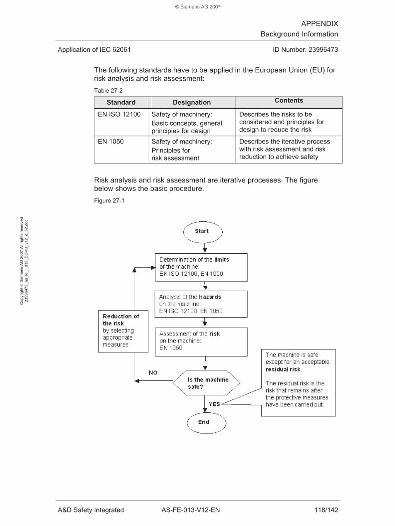
APPENDIXBackground Information
Application of IEC 62061 ID Number: 23996473
A&D Safety Integrated AS-FE-013-V12-EN 118/142
Cop
yrig
ht ©
Sie
men
s A
G 2
007
All
right
s re
serv
ed
2399
6473
_as_
fe_i
_013
_DO
KU
_v12
_e_3
2.do
c
The following standards have to be applied in the European Union (EU) for risk analysis and risk assessment: Table 27-2
Standard Designation Contents
EN ISO 12100 Safety of machinery: Basic concepts, general principles for design
Describes the risks to be considered and principles for design to reduce the risk
EN 1050 Safety of machinery: Principles for risk assessment
Describes the iterative process with risk assessment and risk reduction to achieve safety
Risk analysis and risk assessment are iterative processes. The figure below shows the basic procedure. Figure 27-1
© Siemens AG 2007

APPENDIXBackground Information
Application of IEC 62061 ID Number: 23996473
A&D Safety Integrated AS-FE-013-V12-EN 119/142
Cop
yrig
ht ©
Sie
men
s A
G 2
007
All
right
s re
serv
ed
2399
6473
_as_
fe_i
_013
_DO
KU
_v12
_e_3
2.do
c
27.2 CCF factor (β)
Redundant #subsystems require that the probability of “common cause failures” is considered. These failures cause the simultaneous failure of the redundant components. A measure for this is the CCF factor (β). IEC 62061 (Annex F) provides a method for the estimation of the CCF factor. The table below shows the basic procedure: Table 27-3
Step Activity
1st step Assessment of the #subsystem with regard to the effectiveness of the used measures for protection against “common cause failures”. During this assessment points are awarded for used measures (examples, see table 27-4).
2nd step Determination of the CCF factor from the overall score (see table 27-5): Many measures yield a high overall score.
1st step: Assessment of the #subsystem The table below is an incomplete excerpt from IEC 62061 (table F.1). Table 27-4
Area Measure Score
Separation segregation
Are SRECS signal cables for the individual channels routed separately from other channels at all positions or sufficiently shielded?
5
Diversity redundancy
Do the #subsystem elements have a diagnostic test interval of <= 1 min?
10
Complexity design application
Is cross-connection between channels of the #subsystem prevented with the exception of that used for diagnostic testing purposes?
2
2nd step: Determination of the CCF factor The table below is copied from IEC 62061 (table F.2). The overall score is calculated from the addition of the points applicable to the #subsystem from step 1. Table 27-5
Overall score CCF factor (β)
< 35 10% (0.1) 35 to 65 5% (0.05) 65 to 85 2% (0.02) 85 to 100 1% (0.01)
© Siemens AG 2007

APPENDIXBackground Information
Application of IEC 62061 ID Number: 23996473
A&D Safety Integrated AS-FE-013-V12-EN 120/142
Cop
yrig
ht ©
Sie
men
s A
G 2
007
All
right
s re
serv
ed
2399
6473
_as_
fe_i
_013
_DO
KU
_v12
_e_3
2.do
c
27.3 Failure modes of electrical / electronic components
Electrical / electronic components can fail.
To estimate failure modes and their ratios, IEC 62061 provides a table (IEC 62061, Annex D).
The table below is an incomplete excerpt from IEC 62061 (table D.1). Table 27-6
Component Failure mode Typical failure mode ratios
Contacts will not open 20% Switch with positive opening on demand Contacts will not close 80%
Contacts will not open 50% Electromechanical position switch, … Contacts will not close 50%
All contacts remain in the energized position when the coil is de-energized
25%
All contacts remain in the de-energized position when the coil is energized
25%
Contacts will not open 10% Contacts will not close 10% Simultaneous short circuit between three contacts of a change-over contact
10%
Simultaneous closing of normally open and normally closed contacts
10%
Contactor
Short circuit between two pairs of contacts and/or between contacts and coil terminal
10%
Note: Whether a failure mode on the machine causes a dangerous state or not depends on the respective application.
© Siemens AG 2007
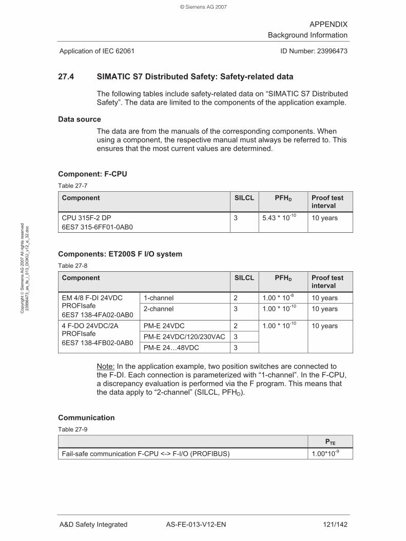
APPENDIXBackground Information
Application of IEC 62061 ID Number: 23996473
A&D Safety Integrated AS-FE-013-V12-EN 121/142
Cop
yrig
ht ©
Sie
men
s A
G 2
007
All
right
s re
serv
ed
2399
6473
_as_
fe_i
_013
_DO
KU
_v12
_e_3
2.do
c
27.4 SIMATIC S7 Distributed Safety: Safety-related data
The following tables include safety-related data on “SIMATIC S7 Distributed Safety”. The data are limited to the components of the application example.
Data source The data are from the manuals of the corresponding components. When using a component, the respective manual must always be referred to. This ensures that the most current values are determined.
Component: F-CPU Table 27-7
Component SILCL PFHD Proof test interval
CPU 315F-2 DP 6ES7 315-6FF01-0AB0
3 5.43 * 10-10 10 years
Components: ET200S F I/O system Table 27-8
Component SILCL PFHD Proof test interval
1-channel 2 1.00 * 10-8 10 years EM 4/8 F-DI 24VDC PROFIsafe 6ES7 138-4FA02-0AB0
2-channel 3 1.00 * 10-10 10 years
PM-E 24VDC 2 PM-E 24VDC/120/230VAC 3
4 F-DO 24VDC/2A PROFIsafe 6ES7 138-4FB02-0AB0
PM-E 24…48VDC 3
1.00 * 10-10 10 years
Note: In the application example, two position switches are connected to the F-DI. Each connection is parameterized with “1-channel”. In the F-CPU, a discrepancy evaluation is performed via the F program. This means that the data apply to “2-channel” (SILCL, PFHD).
Communication Table 27-9
PTE
Fail-safe communication F-CPU <-> F-I/O (PROFIBUS) 1.00*10-9
© Siemens AG 2007

APPENDIXBackground Information
Application of IEC 62061 ID Number: 23996473
A&D Safety Integrated AS-FE-013-V12-EN 122/142
Cop
yrig
ht ©
Sie
men
s A
G 2
007
All
right
s re
serv
ed
2399
6473
_as_
fe_i
_013
_DO
KU
_v12
_e_3
2.do
c
27.5 SIRIUS: Safety-related data
The following table includes safety-related data on components of the “SIRIUS” series. The data are limited to the components of the application example.
Data source The data are from a recommendation of the A&D CD (of 02/01/06):
• “Recommendation of the standard B10 values for the application of EN 62061”
An analogous summary is listed below:
Recommendation of the standard B10 values for the application of EN 62061 The failure rate of electromechanical components is described by the “B10 value”. The B10 value is defined as follows:
• B10 is the number of switching cycles after which 10% of the test objects have failed.
According to EN 62061, the failure rate of the electromechanical components can be calculated from the B10 value:
• λ = 0.1 * C / B10
• C = operation per hour (depends on the application)
Composition of the failure rate:
• λ = λS + λD
• λS = safe failure fraction in % (“safe”)
• λD = dangerous failure fraction in % (“dangerous”)
The table below shows excerpts of the SIRIUS standard B10 values for electromechanical components. Table 27-10
Component B10 value λd
Position switch with separate actuator (with positively opening contacts)
1.000.000 20%
Contactor / motor starter (with positively driven contacts)
1.000.000 75%
© Siemens AG 2007

APPENDIXBackground Information
Application of IEC 62061 ID Number: 23996473
A&D Safety Integrated AS-FE-013-V12-EN 123/142
Cop
yrig
ht ©
Sie
men
s A
G 2
007
All
right
s re
serv
ed
2399
6473
_as_
fe_i
_013
_DO
KU
_v12
_e_3
2.do
c
27.6 Fault, diagnostics and failure (according to IEC 62061)
The terms fault and failure are of great importance when applying IEC 62061. To illustrate this importance, simple examples will be used to explain the terms in this chapter. The exact definitions of the terms according to IEC 62061 are listed in chapter 28.1.
27.6.1 Fault
A #safety system (SRECS) must be realized in such a way that it meets all requirements according to the required SIL.
The objective during the realization is to minimize he probability of dangerous systematic and random faults.
Faults Faults affect the function of:
• SRECS or
• #subsystem or
• #subsystem element.
Faults cause that the required function is no longer performed:
• Loss of the function
If a fault causes the loss of the function of a #subsystem, all #safety-related control functions (SRCFs) using this subsystem are no longer performed:
• Loss of the SRCF
The loss of the #safety-related control function (SRCF) may cause the loss of the #safety function
Explanation of “may”:
“Loss of the SRCF” means that the required function of the SRCF is no longer performed.
The fault may be detected by diagnostics by other (not assigned to the SRCF) measures in the SRECS. A fault reaction of the SRECS can prevent the occurrence of a dangerous state on the machine. This means that the #safety function is eventually complied with by a second way (independent of the SRCF).
Examples for clarification: Chapter 27.6.4
© Siemens AG 2007

APPENDIXBackground Information
Application of IEC 62061 ID Number: 23996473
A&D Safety Integrated AS-FE-013-V12-EN 124/142
Cop
yrig
ht ©
Sie
men
s A
G 2
007
All
right
s re
serv
ed
2399
6473
_as_
fe_i
_013
_DO
KU
_v12
_e_3
2.do
c
Dangerous and safe faults All faults can be divided into one of the two classes:
• Dangerous faults
• Safe faults
Dangerous faults cause dangerous failures, safe faults cause safe failures (chapter 27.6.3).
Random and systematic faults Faults (dangerous or safe faults) can be:
• Random or
• systematic
Characteristics of a “random fault”:
• Fault in the hardware occurring at a random instant of time. The fault causes that a required function is no longer performed.
• The fault is subject to quantification by IEC 62061. The quantification is based on the failure rates. These are, for example, the B10 values of electromechanical components (information of the manufacturer of the components).
Examples of random faults:
• Break of the actuator of a position switch
• Contacts of a contactor do not open
Characteristics of a “systematic fault”:
• Fault in the hardware or application software that is related to a specific cause. The cause of the fault can be corrected by the following measures (examples):
– Modification of the design
– Modification of the selection of the used components
• The fault is not subject to quantification by IEC 62061.
© Siemens AG 2007

APPENDIXBackground Information
Application of IEC 62061 ID Number: 23996473
A&D Safety Integrated AS-FE-013-V12-EN 125/142
Cop
yrig
ht ©
Sie
men
s A
G 2
007
All
right
s re
serv
ed
2399
6473
_as_
fe_i
_013
_DO
KU
_v12
_e_3
2.do
c
Examples of systematic faults:
• Errors in the specification of the SRCF
• Errors in the design, manufacture, installation or the operation of the hardware
• Errors in the design or implementation of the application software
• Short circuit, wire break on lines
27.6.2 Diagnostics
Objective of the diagnostics:
• Diagnostics are used to detect random and systematic dangerous faults in the hardware.
• Diagnostics and corresponding fault reaction prevent that a dangerous fault causes a dangerous state on the machine.
Characteristics of the “diagnostics”:
• Diagnostics must be performed within the SRECS.
• Diagnostics of a #subsystem can be performed at the following locations:
– In the actual #subsystem
– Outside the #subsystem, in another #subsystem
• Diagnostics are automatically performed by the SRCES (example: Readback of contactors).
• Diagnostics improve the #safe failure fraction (SFF) and the #PFHD value (PFHD) of a #subsystem.
Use of SIMATIC standard modules for diagnostics:
• Example: Use of standard modules (thus no F modules ) for reading in readback signals of contactors.
• Standard modules may be used for diagnostics in the SRECS when dangerous faults are detected in the F program of the F-CPU.
• The diagnostic device is not subject to quantification if the following requirements are met:
– Diagnostics are performed in the F program of the F-CPU.
– The diagnostic device is cyclically monitored in the F program of the F-CPU.
© Siemens AG 2007

APPENDIXBackground Information
Application of IEC 62061 ID Number: 23996473
A&D Safety Integrated AS-FE-013-V12-EN 126/142
Cop
yrig
ht ©
Sie
men
s A
G 2
007
All
right
s re
serv
ed
2399
6473
_as_
fe_i
_013
_DO
KU
_v12
_e_3
2.do
c
27.6.3 Failure
Fault and failure Faults cause failures of:
• SRECS or
• #subsystem or
• #subsystem element.
A “failure” is defined as follows:
• Termination of the ability of a SRECS, a #subsystem or a #subsystem element to perform a required function.
• A failure of a #subsystem causes the loss of all SRCFs using this #subsystem.
• A failure of a #subsystem element in a #subsystem does not necessarily cause the loss of all SRCFs using this #subsystem.
Role of diagnostics In the event of a failure of a SRCF (“first switch-off option” failure), the #safety function does not necessarily have to fail. If diagnostics (fault detection) are provided in the SRECS, the #safety function can be maintained by corresponding fault reaction (“second switch-off option”).
The model shown below is the basis: Figure 27-2
© Siemens AG 2007
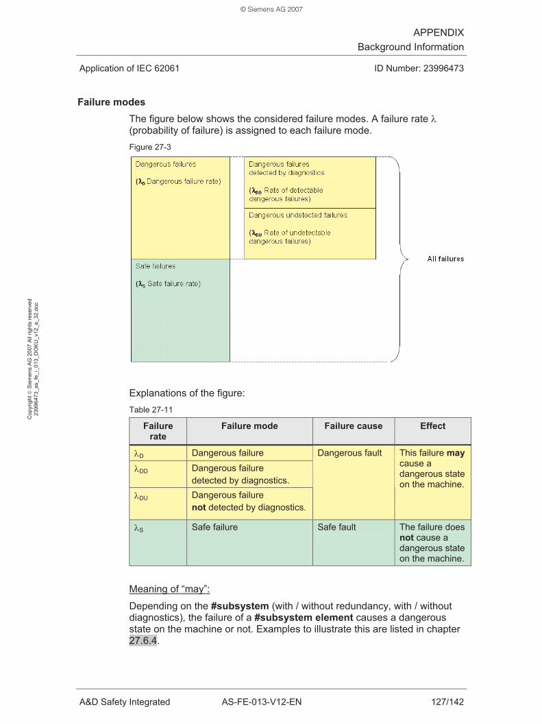
APPENDIXBackground Information
Application of IEC 62061 ID Number: 23996473
A&D Safety Integrated AS-FE-013-V12-EN 127/142
Cop
yrig
ht ©
Sie
men
s A
G 2
007
All
right
s re
serv
ed
2399
6473
_as_
fe_i
_013
_DO
KU
_v12
_e_3
2.do
c
Failure modes The figure below shows the considered failure modes. A failure rate λ (probability of failure) is assigned to each failure mode. Figure 27-3
Explanations of the figure: Table 27-11
Failure rate
Failure mode Failure cause Effect
λD Dangerous failure
λDD Dangerous failure detected by diagnostics.
λDU Dangerous failure not detected by diagnostics.
Dangerous fault
This failure may cause a dangerous state on the machine.
λS Safe failure Safe fault
The failure does not cause a dangerous state on the machine.
Meaning of “may”:
Depending on the #subsystem (with / without redundancy, with / without diagnostics), the failure of a #subsystem element causes a dangerous state on the machine or not. Examples to illustrate this are listed in chapter 27.6.4.
© Siemens AG 2007
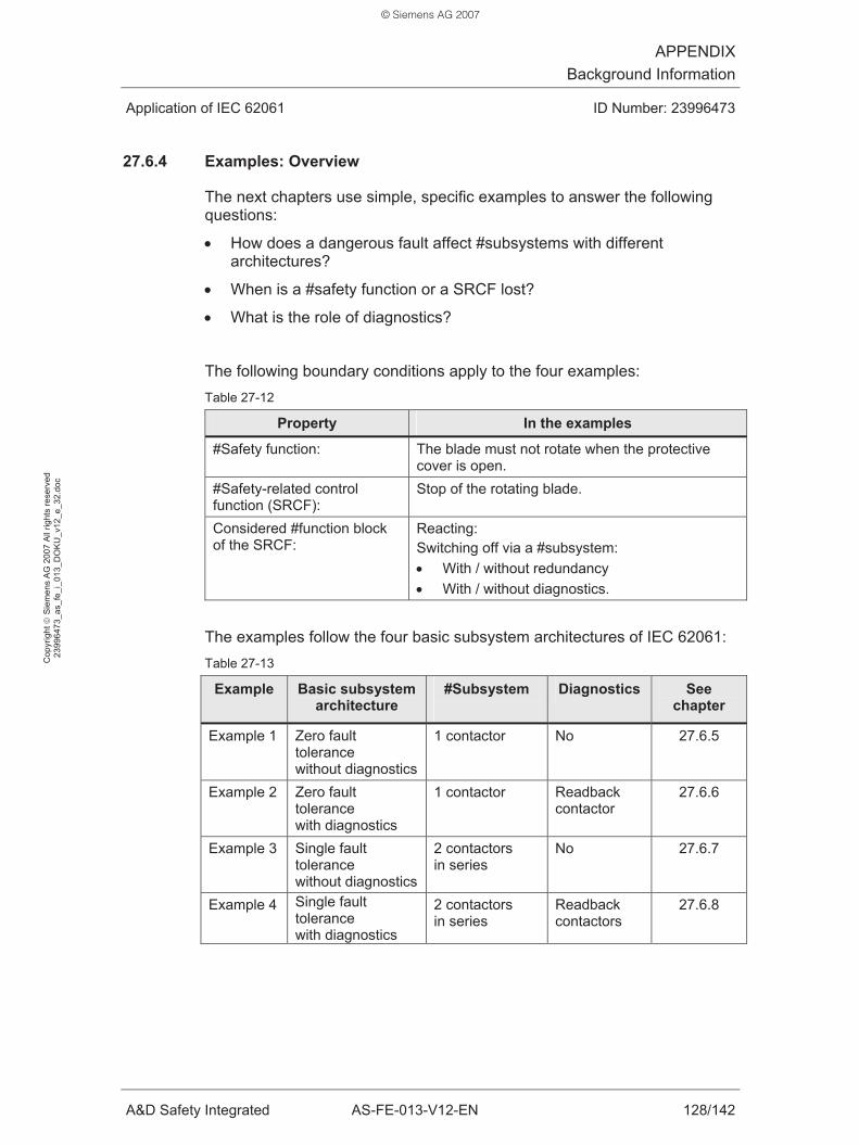
APPENDIXBackground Information
Application of IEC 62061 ID Number: 23996473
A&D Safety Integrated AS-FE-013-V12-EN 128/142
Cop
yrig
ht ©
Sie
men
s A
G 2
007
All
right
s re
serv
ed
2399
6473
_as_
fe_i
_013
_DO
KU
_v12
_e_3
2.do
c
27.6.4 Examples: Overview
The next chapters use simple, specific examples to answer the following questions:
• How does a dangerous fault affect #subsystems with different architectures?
• When is a #safety function or a SRCF lost?
• What is the role of diagnostics?
The following boundary conditions apply to the four examples: Table 27-12
Property In the examples
#Safety function:
The blade must not rotate when the protective cover is open.
#Safety-related control function (SRCF):
Stop of the rotating blade.
Considered #function block of the SRCF:
Reacting: Switching off via a #subsystem: • With / without redundancy • With / without diagnostics.
The examples follow the four basic subsystem architectures of IEC 62061: Table 27-13
Example Basic subsystem architecture
#Subsystem
Diagnostics See chapter
Example 1 Zero fault tolerance without diagnostics
1 contactor No 27.6.5
Example 2 Zero fault tolerance with diagnostics
1 contactor Readback contactor
27.6.6
Example 3 Single fault tolerance without diagnostics
2 contactors in series
No 27.6.7
Example 4 Single fault tolerance with diagnostics
2 contactors in series
Readback contactors
27.6.8
© Siemens AG 2007

APPENDIXBackground Information
Application of IEC 62061 ID Number: 23996473
A&D Safety Integrated AS-FE-013-V12-EN 129/142
Cop
yrig
ht ©
Sie
men
s A
G 2
007
All
right
s re
serv
ed
2399
6473
_as_
fe_i
_013
_DO
KU
_v12
_e_3
2.do
c
27.6.5 Example 1: Zero fault tolerance without diagnostics
#Subsystem #Subsystem: 1 contactor
Fault scenario: Contacts of the contactor do not open Effects: Table 27-14
Effect Explanation
Loss of the SRCF:
Yes The #subsystem cannot perform the required function.
Loss of the #safety function:
Yes Due to loss of the SRCF and the missing diagnostics.
Fault type: Dangerous The fault causes a dangerous state on the machine.
States on the machine The figure below shows the sequences and events on the machine. Figure 27-4
© Siemens AG 2007

APPENDIXBackground Information
Application of IEC 62061 ID Number: 23996473
A&D Safety Integrated AS-FE-013-V12-EN 130/142
Cop
yrig
ht ©
Sie
men
s A
G 2
007
All
right
s re
serv
ed
2399
6473
_as_
fe_i
_013
_DO
KU
_v12
_e_3
2.do
c
27.6.6 Example 2: Zero fault tolerance with diagnostics
#Subsystem #Subsystem: 1 contactor, with diagnostics by readback
Fault scenario: Contacts of the contactor do not open Effects of the fault: Table 27-15
Effect Explanation
Loss of the SRCF:
Yes The #subsystem cannot perform the required function.
Loss of the #safety function:
No The SRECS detects the fault (diagnostics). The fault reaction of the SRECS ensures that no dangerous state occurs on the machine.
Fault type: Dangerous The fault may cause a dangerous state on the machine: In the event of a diagnostics failure, a dangerous state would occur on the machine.
Effects of the diagnostics:
• Switching off using a second option
• Restart of the machine is prevented until the fault has been corrected.
States on the machine The figure below shows the sequences and events on the machine. Figure 27-5
© Siemens AG 2007

APPENDIXBackground Information
Application of IEC 62061 ID Number: 23996473
A&D Safety Integrated AS-FE-013-V12-EN 131/142
Cop
yrig
ht ©
Sie
men
s A
G 2
007
All
right
s re
serv
ed
2399
6473
_as_
fe_i
_013
_DO
KU
_v12
_e_3
2.do
c
27.6.7 Example 3: Single fault tolerance without diagnostics
#Subsystem: #Subsystem: 2 contactors in series
Fault scenario 1: Contacts of a single contactor do not open Effects Table 27-16
Effect Explanation
Loss of the SRCF:
No The #subsystem can perform the required function while the second contactor is faultless.
Loss of the #safety function:
No No loss of the SRCF (see above).
Fault type: Dangerous The fault may cause a dangerous state on the machine: In the event of a failure of the second contactor, a dangerous state would occur on the machine.
States on the machine
The figure below shows the sequences and events on the machine. Figure 27-6
© Siemens AG 2007

APPENDIXBackground Information
Application of IEC 62061 ID Number: 23996473
A&D Safety Integrated AS-FE-013-V12-EN 132/142
Cop
yrig
ht ©
Sie
men
s A
G 2
007
All
right
s re
serv
ed
2399
6473
_as_
fe_i
_013
_DO
KU
_v12
_e_3
2.do
c
Fault scenario 2: Contacts of both contactors do not open Effects Table 27-17
Effect Explanation
Loss of the SRCF: Yes The #subsystem cannot perform the required function.
Loss of the #safety function:
Yes Due to loss of the SRCF and the missing diagnostics.
Fault type: Dangerous The fault causes a dangerous state on the machine.
States on the machine
The figure below shows the sequences and events on the machine. Figure 27-7
© Siemens AG 2007

APPENDIXBackground Information
Application of IEC 62061 ID Number: 23996473
A&D Safety Integrated AS-FE-013-V12-EN 133/142
Cop
yrig
ht ©
Sie
men
s A
G 2
007
All
right
s re
serv
ed
2399
6473
_as_
fe_i
_013
_DO
KU
_v12
_e_3
2.do
c
27.6.8 Example 4: Single fault tolerance with diagnostics
#Subsystem: #Subsystem: 2 contactors in series, with diagnostics via readback.
Fault scenario 1: Contacts of a single contactor do not open Effects Table 27-18
Effect Explanation
Loss of the SRCF: No The #subsystem can perform the required function while the second contactor is faultless.
Loss of the #safety function:
No No loss of the SRCF (see above).
Fault type: Dangerous The fault may cause a dangerous state on the machine: In the event of a failure of the second contactor and a failure of the diagnostics, a dangerous state would occur on the machine.
Effects of the diagnostics:
• Switching off using second option
• Restart of the machine is prevented until the fault has been corrected.
States on the machine
The figure below shows the sequences and events on the machine. Figure 27-8
© Siemens AG 2007

APPENDIXBackground Information
Application of IEC 62061 ID Number: 23996473
A&D Safety Integrated AS-FE-013-V12-EN 134/142
Cop
yrig
ht ©
Sie
men
s A
G 2
007
All
right
s re
serv
ed
2399
6473
_as_
fe_i
_013
_DO
KU
_v12
_e_3
2.do
c
Fault scenario 2: Contacts of both contactors do not open Effects Table 27-19
Effect Explanation
Loss of the SRCF: Yes The #subsystem cannot perform the required function.
Loss of the #safety function:
No The SRECS detects the fault (diagnostics). The fault reaction of the SRECS ensures that no dangerous state occurs on the machine.
Type of the faults: Dangerous The faults may cause a dangerous state on the machine: In the event of a diagnostics failure, a dangerous state would occur on the machine.
Effects of the diagnostics:
• Switching off using second option
• Restart of the machine is prevented until the fault has been corrected.
States on the machine
The figure below shows the sequences and events on the machine. Figure 27-9
Figure 27-10
© Siemens AG 2007

APPENDIXBackground Information
Application of IEC 62061 ID Number: 23996473
A&D Safety Integrated AS-FE-013-V12-EN 135/142
Cop
yrig
ht ©
Sie
men
s A
G 2
007
All
right
s re
serv
ed
2399
6473
_as_
fe_i
_013
_DO
KU
_v12
_e_3
2.do
c
27.7 Category according to EN 954-1: 1996
The categories define the required behavior of safety-related parts of a control system relating to their resistance to faults. The table provides an overview of the categories according to EN 954-1: 1996.
Table 27-20
EN 954-1: 1996
Cat
egor
y Summary of requirements System behavior Principles to achieve safety
B The safety-related parts of control systems and/or their protective equipment, as well as their components, shall be designed, constructed selected, assembled and combined in accordance with relevant standards so that they can withstand the expected influence.
The occurrence of a fault can lead to the loss of the safety function.
1 The requirements of B shall apply. Well-proven components and well-proven safety principles must be applied.
The occurrence of a fault can result in the loss of the safety function, but the probability of occurrence is less than in Category B.
Mainly characterized by selection of components
2 The requirements of B and the use of well-proven safety principles must be fulfilled. The safety function shall be checked at suitable intervals by the machine control system.
The occurrence of a fault can lead to the loss of the safety function between the checks. The loss of the safety function is detected by the check.
3 The requirements of B and the use of well-proven safety principles must be fulfilled. Safety-related parts shall be designed, so that: 1. a single fault in any of these parts does not lead to the loss of the safety function, and 2. whenever reasonably practicable, the single fault is detected.
If the individual fault occurs, the safety function always remains. Some but not all faults will be detected. Accumulation of undetected faults can lead to the loss of the safety function.
4 The requirements of B and the use of well-proven safety principles must be fulfilled. Safety-related parts shall be designed, so that: 1. a single fault in any of these parts does not lead to the loss of the safety function, and 2. the single fault is detected at or before the next demand upon the safety function. If this is not possible, then an accumulation of faults shall not lead to a loss of the safety function.
If faults occur, the safety function always remains. Detection of accumulated faults reduces the probability of the loss of the safety function. The faults will be detected in time to prevent the loss of the safety function.
Mainly characterized by structure
© Siemens AG 2007
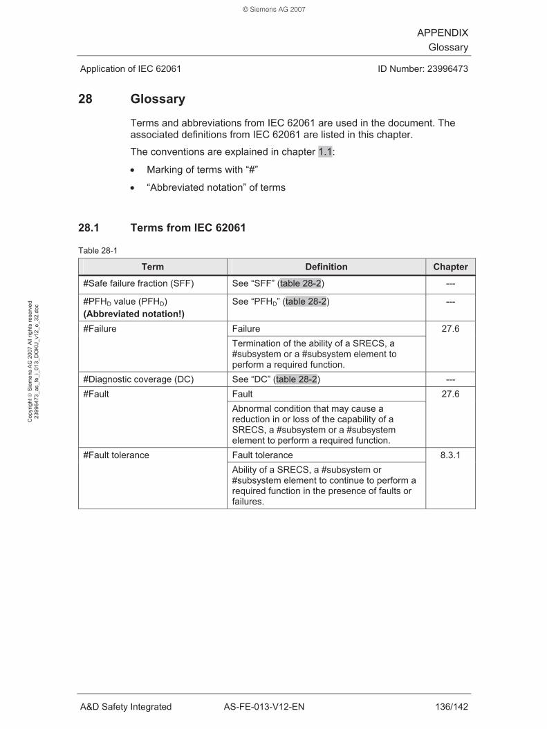
APPENDIXGlossary
Application of IEC 62061 ID Number: 23996473
A&D Safety Integrated AS-FE-013-V12-EN 136/142
Cop
yrig
ht ©
Sie
men
s A
G 2
007
All
right
s re
serv
ed
2399
6473
_as_
fe_i
_013
_DO
KU
_v12
_e_3
2.do
c
28 Glossary
Terms and abbreviations from IEC 62061 are used in the document. The associated definitions from IEC 62061 are listed in this chapter.
The conventions are explained in chapter 1.1:
• Marking of terms with “#”
• “Abbreviated notation” of terms
28.1 Terms from IEC 62061
Table 28-1
Term Definition Chapter
#Safe failure fraction (SFF) See “SFF” (table 28-2) ---
#PFHD value (PFHD) (Abbreviated notation!)
See “PFHD” (table 28-2)
---
Failure #Failure Termination of the ability of a SRECS, a #subsystem or a #subsystem element to perform a required function.
27.6
#Diagnostic coverage (DC) See “DC” (table 28-2) --- Fault #Fault Abnormal condition that may cause a reduction in or loss of the capability of a SRECS, a #subsystem or a #subsystem element to perform a required function.
27.6
Fault tolerance #Fault tolerance Ability of a SRECS, a #subsystem or #subsystem element to continue to perform a required function in the presence of faults or failures.
8.3.1
© Siemens AG 2007
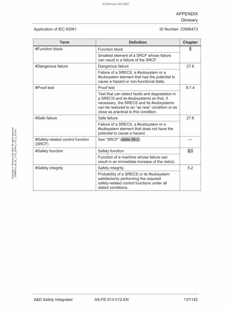
APPENDIXGlossary
Application of IEC 62061 ID Number: 23996473
A&D Safety Integrated AS-FE-013-V12-EN 137/142
Cop
yrig
ht ©
Sie
men
s A
G 2
007
All
right
s re
serv
ed
2399
6473
_as_
fe_i
_013
_DO
KU
_v12
_e_3
2.do
c
Term Definition Chapter
Function block #Function block
Smallest element of a SRCF whose failure can result in a failure of the SRCF
5
Dangerous failure #Dangerous failure Failure of a SRECS, a #subsystem or a #subsystem element that has the potential to cause a hazard or non-functional state.
27.6
Proof test #Proof test Test that can detect faults and degradation in a SRECS and its #subsystems so that, if necessary, the SRECS and its #subsystems can be restored to an “as new” condition or as close as practical to this condition.
9.7.4
Safe failure #Safe failure Failure of a SRECS, a #subsystem or a #subsystem element that does not have the potential to cause a hazard.
27.6
#Safety-related control function (SRCF)
See “SRCF” (table 28-2)
---
Safety function #Safety function Function of a machine whose failure can
result in an immediate increase of the risk(s).
5.1
Safety integrity #Safety integrity Probability of a SRECS or its #subsystem satisfactorily performing the required safety-related control functions under all stated conditions.
5.2
© Siemens AG 2007
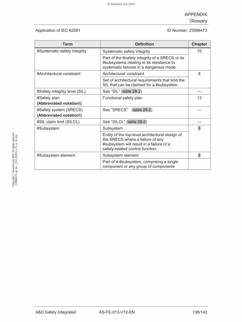
APPENDIXGlossary
Application of IEC 62061 ID Number: 23996473
A&D Safety Integrated AS-FE-013-V12-EN 138/142
Cop
yrig
ht ©
Sie
men
s A
G 2
007
All
right
s re
serv
ed
2399
6473
_as_
fe_i
_013
_DO
KU
_v12
_e_3
2.do
c
Term Definition Chapter
Systematic safety integrity #Systematic safety integrity
Part of the #safety integrity of a SRECS or its #subsystems relating to its resistance to systematic failures in a dangerous mode.
10
Architectural constraint #Architectural constraint Set of architectural requirements that limit the SIL that can be claimed for a #subsystem.
8
#Safety integrity level (SIL) See “SIL” (table 28-2) --- #Safety plan (Abbreviated notation!)
Functional safety plan 13
#Safety system (SRECS) (Abbreviated notation!)
See “SRECS” (table 28-2)
---
#SIL claim limit (SILCL) See “SILCL” (table 28-2) --- Subsystem #Subsystem Entity of the top-level architectural design of the SRECS where a failure of any #subsystem will result in a failure of a safety-related control function.
6
Subsystem element 6 #Subsystem element Part of a #subsystem, comprising a single component or any group of components
© Siemens AG 2007
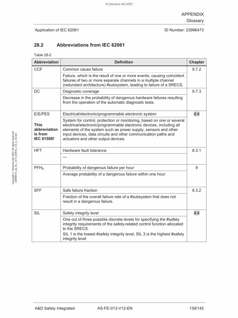
APPENDIXGlossary
Application of IEC 62061 ID Number: 23996473
A&D Safety Integrated AS-FE-013-V12-EN 139/142
Cop
yrig
ht ©
Sie
men
s A
G 2
007
All
right
s re
serv
ed
2399
6473
_as_
fe_i
_013
_DO
KU
_v12
_e_3
2.do
c
28.2 Abbreviations from IEC 62061
Table 28-2
Abbreviation Definition Chapter
Common cause failure CCF
Failure, which is the result of one or more events, causing coincident failures of two or more separate channels in a multiple channel (redundant architecture) #subsystem, leading to failure of a SRECS.
9.7.2
Diagnostic coverage DC
Decrease in the probability of dangerous hardware failures resulting from the operation of the automatic diagnostic tests.
9.7.3
Electrical/electronic/programmable electronic system E/E/PES This abbreviation is from IEC 61508!
System for control, protection or monitoring, based on one or several electrical/electronic/programmable electronic devices, including all elements of the system such as power supply, sensors and other input devices, data circuits and other communication paths and actuators and other output devices.
4.4
Hardware fault tolerance HFT
--- 8.3.1
Probability of dangerous failure per hour PFHD
Average probability of a dangerous failure within one hour. 9
Safe failure fraction SFF
Fraction of the overall failure rate of a #subsystem that does not result in a dangerous failure.
8.3.2
Safety integrity level SIL
One out of three possible discrete levels for specifying the #safety integrity requirements of the safety-related control function allocated to the SRECS. SIL 1 is the lowest #safety integrity level, SIL 3 is the highest #safety integrity level
4.4
© Siemens AG 2007

APPENDIXGlossary
Application of IEC 62061 ID Number: 23996473
A&D Safety Integrated AS-FE-013-V12-EN 140/142
Cop
yrig
ht ©
Sie
men
s A
G 2
007
All
right
s re
serv
ed
2399
6473
_as_
fe_i
_013
_DO
KU
_v12
_e_3
2.do
c
Abbreviation Definition Chapter
SIL claim limit for a #subsystem SILCL
Maximum SIL that can be claimed for a SRECS #subsystem in relation to architectural constraints and #systematic safety integrity.
8.1
Safety-related control function SRCF
Control function implemented by a SRECS with a specified integrity level that is intended to maintain the safe condition of the machine or prevent an immediate increase of the risk(s).
5
Safety-related electrical control system SRECS
Electrical control system of a machine whose failure can result in an immediate increase of the risk(s). A SRECS includes all parts of an electrical control system whose failure may result in a reduction or loss of functional safety. This can comprise both electrical power circuits and control circuits.
6
28.3 General abbreviations
Generally valid abbreviations are explained in the following table. Table 28-3
Abbreviation Meaning
F-CPU Fail-safe CPU F-DI Fail-safe digital input module F-DO Fail-safe digital output module F-PLC Fail-safe programmable logic controller PLC Programmable logic controller F program Part of the user program: Fail-safe program S program Part of the user program: Standard program
© Siemens AG 2007

APPENDIXInformation Directory
Application of IEC 62061 ID Number: 23996473
A&D Safety Integrated AS-FE-013-V12-EN 141/142
Cop
yrig
ht ©
Sie
men
s A
G 2
007
All
right
s re
serv
ed
2399
6473
_as_
fe_i
_013
_DO
KU
_v12
_e_3
2.do
c
29 Information Directory
Table 29-1
/x/ Information Link / order number
/1/ Ordering standards http://www.iec-normen.de
/2/ Official status of a standard http://www.dke.de
/3/ Lists of harmonized standards in the Official Journal of the European Union
http://www.newapproach.org/
/4/ Safety Integrated System Manual
http://support.automation.siemens.com/WW/view/en/17711888
http://support.automation.siemens.com /5/ Functional Examples (See “Preliminary remark” on page 2 of the document)
Order number for manual and CD: 6ZB5310-0MK01-0BA0
/6/ Safety Integrated at Siemens
http://www.automation.siemens.com/cd/safety/index_76.htm
© Siemens AG 2007

APPENDIXHistory of the Document
Application of IEC 62061 ID Number: 23996473
A&D Safety Integrated AS-FE-013-V12-EN 142/142
Cop
yrig
ht ©
Sie
men
s A
G 2
007
All
right
s re
serv
ed
2399
6473
_as_
fe_i
_013
_DO
KU
_v12
_e_3
2.do
c
30 History of the Document
Table 30-1
Version Date Modifications compared to previous document
V1.0 09 / 2006 First edition. Reason: Version V1.0 was reviewed by the Center for Quality Engineering (CQE). Correction (*1): • --- Editorial amendments of chapters (*2): • Page 2 (“Note”) • Chapter 1 • Chapter 4.2, 4.3 • Chapter 5.1, 5.2 • Chapter 6 • Chapter 7.1, 7.2 • Chapter 8.3.1
• Chapter 9.2 • Chapter 10 • Chapter 12.2 • Chapter 13.2, 13.3 • Chapter 14 • Chapter 15.1, 15.2.1, 15.3.3 • Chapter 27.1, 27.6.1, 27.6.2, 27.6.3 • Chapter 28
New chapters added: • Chapter 30 Changed terms: • #PFHD value (PFHD) instead of #probability of failure (PFHD) • #Function block instead of subfunction • #Subsystem instead of subsystem • Risk analysis instead of hazard analysis • Evaluating instead of processing (function block) • Reacting instead of executing (function block)
V1.1 03 / 2007
Changed designation for the application example’s SRCF: “Stop of the rotating blade” instead of “When the protective cover is opened, the motor is switched off”.
V1.2 08 / 2007 • Layout changed (title, headline) • Chapter 30 deleted
Explanations of the above table: Table 30-2
(*x) Explanations
(*1) Significant corrections are listed here: Formula, calculation, statement, ...
(*2) Significant editorial amendments are listed here: Wording, extension, structure, ...
© Siemens AG 2007

Notes
U3 _U4_en.fm Seite 1 Mittwoch, 8. August 2007 1:50 13
© Siemens AG 2007

2
Siemens AG
Automation and DrivesSafety IntegratedPostfach 48 4890327 NÜRNBERGDEUTSCHLAND
www.siemens.com/automation/ser vice&suppor t
The information provided in this Functional Example contains descriptions or characteristics of performance which in case of actual use do not always apply as described or which may change as a result of further development of the pro-ducts. An obligation to provide the respective characteristics shall only exist if expressly agreed in the terms of contract. Availability and technical specifica-tions are subject to change without notice..
All product designations may be trademarks or product names of Siemens AG or supplier companies whose use by third parties for their own purposes could violate the rights of the owners.
Subj
ect
to c
han
ge w
ith
out
prio
r n
o tic
e |
Dis
po 2
61
00
| 7
01
70
1 H
B 0
80
7 5
.0 W
E 1
40
En
| P
rin
ted
in G
erm
any
| ©
Sie
men
s A
G 2
00
7
Order No. 6ZB5310-0NM02-0BA0
ywww.siemens.com/safety
U3 _U4_en.fm Seite 2 Mittwoch, 8. August 2007 1:50 13
© Siemens AG 2007