functional safety and detection gas detection systems ... · sil 1 a – sil 1 sil 1 a sil 2 sil 1...
TRANSCRIPT
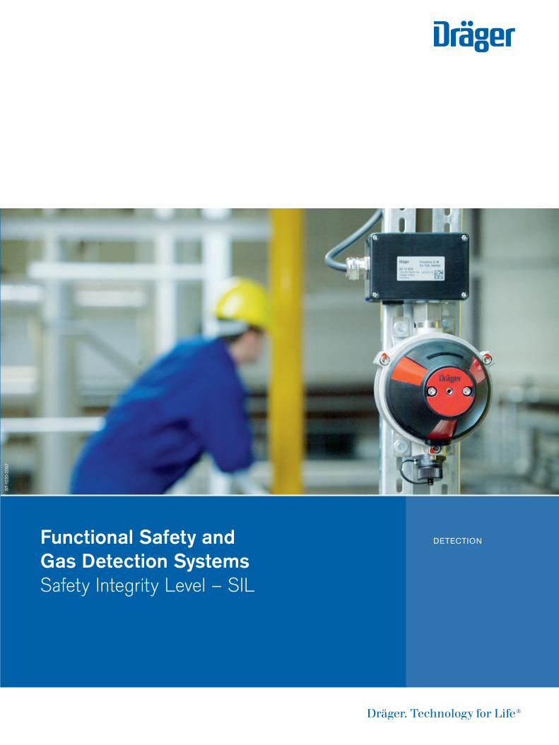
Functional Safety andGas Detection SystemsSafety Integrity Level – SIL
DETECTION
ST-
1220
-200
7
9046256_AB_SIL_Funktionale_Sicherheit_engl:3 16.04.10 08:15 Seite 1
02 | RISK REDUCTION | SIL - SAFETY INTEGRITY LEVEL AND FUNCTIONAL SAFETY
Safety Instrumented Systems are used to reduce the risk for the protection of people, plants, and environment.
Depending on the way a process is designed and what kind of dangerous goods (especiallygases and vapours) are involved, industrial plants might pose a high risk to persons, property, and environment. In order to reduce the risk arising from those plants it might be necessary to automatically activate safety measures to avoid dangerous situations.
Depending on the acceptable risk therequired reliability of protection systemscan be ensured by employing the effectivemeasures of– failure avoidance,– failure detection, and– failure tolerance
This to a degree depends on the actualrisk, the so-called Safety Integrity Level.
For gas detection systems, which have toactivate safety relevant countermeasures incase of pre-defined gas concentrations, animportant question comes up: What is theprobability of failing to perform the requiredcountermeasure (safety function) in caseof a demand from the process (meanswhen pre-defined gas concentrations havebeen exceeded) if an undetectable danger-ous failure has occurred?
So, during development and design ofdevices and subsystems of safety relevantsystems the main target is to keep the probability of failure as low as possible (failure avoidance), or to detect failures by diagnostic functions (failure detection)and – in case of a detected failure –to force the safety system to go into a safestate (failure tolerance).
Risk analysisDepending on the extent of threat to per-sons, property and environment there arefour different classes of risk. Generally arisk is a combination of the consequenceto be expected and the probability of occurrence of such an unwanted hazard.
To classify the actual risk structured methods are used, e.g. the risk graph. Therisk graph is based on four different consequence categories, and the probabilityaspect is implemented by the criteria “frequency of exposure of persons” and the“possibility of avoiding the hazardousevent”.
Such risk analysis can only be conductedby highly qualified persons who are familiarwith the process-specific conditions. As a result the risk analysis leads to thedefini tion of the necessary risk-reducingmeasures, combined with the – definition of the safety function and the – required Safety Integrity Level
Residual riskIf the functional safety is realized by anelectrical, electronic or programmableelectronic system (“E/E/PES”), the appli-cable standard IEC 61508 or EN 61508requires evidence of the remaining residual
risk by identifying the so-called dangerousprobability of failure as a measure of theprotection system’s reliability.
FailuresConsidering the entire operational time noE/E/PES is absolutely free of failures.Always there might be systematic or accidental failures, and wear-out partsneed to be considered. However, consum-able components are not subject to theSIL-consideration – they have to bereplaced ensuring failures caused by consumption shall not occur.
Systematic failures… are design- or development-failures,which already exist at the time of deliveryand which are reproducible (e.g. softwarefailures, incorrect rating or the operation of electronic components outside of their specification). By organizationalmeasures and safety-orientated develop-ment procedures, systematic failures,especially software failures, can be mini-mized.
Accidental failures… are inevitable characteristic properties of components. They do not exist at thetime of delivery, but will occur at any timeduring operation. Accidental failures arespecified by a so-called constant failurerate λ which says that during equivalenttime intervals always the same percentageof components will fail. The manufacturerderives this failure rate by means of special stress tests with a large number ofcomponents and determines or forecaststhe time at which 63 percent of the com-ponents have failed. The reciprocal valueof the resulting time, the so-called MTTF +
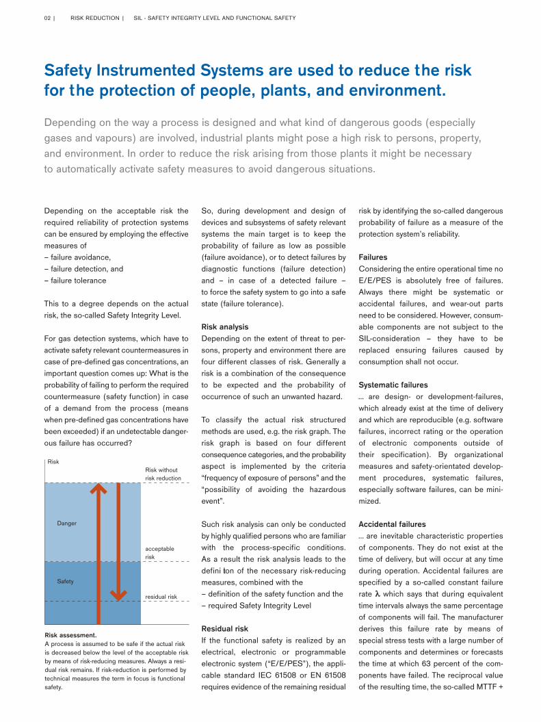
Risk assessment.A process is assumed to be safe if the actual riskis decreased below the level of the acceptable riskby means of risk-reducing measures. Always a resi-dual risk remains. If risk-reduction is performed bytechnical measures the term in focus is functionalsafety.
Risk without risk reduction
Danger
Safety
acceptable risk
Risk
residual risk
9046256_AB_SIL_Funktionale_Sicherheit_engl:3 16.04.10 08:15 Seite 2
λ is a mere statistical value which howeverenables engineers to calculate the proba-bility that a failure will occur.
Probability of failureAnd statistics predict even more: If forexample 340 of 1000 equivalent deviceshave failed after 12 months in operation,then statistics predict a probability of failureof 34 percent for a single device.
The probability of failure continuously riseswith operational time, and at the time ofMTTF for a considered device this proba-bility is 63 percent.
Needless to say that this can also be trans-ferred to the safety function: Consideringa system which in case of danger needs toperform the safety function, then the prob-ability not to perform the safety function iszero at the time of function test (time 0),and the device is absolutely reliable. Butthe probability of failure rises continuously,and so does the probability that the safetyfunction will not be performed. However,after having tested the safety functionagain, e.g. after reconditioning, and the testproved to be successful, then again theprobability of failure is zero. So one canreset the probability of failure at regularintervals, because at least at the time ofsuccessful proof test of the safety functionthe system is 100 % reliable!
The average value of the resulting zigzag-curve can be expressed as a number: Multiplying half the proof test interval TPwith the failure rate λ leads to the averageProbability of Failure On Demand or PFD:PFDavg = 0.5·λ·TP
It is called On Demand because althoughthe safety system is continuously in opera-tion a demand to perform its safety functionis seldom, say less than once a year. Thiskind of operation called Low DemandMode is typical for safety systems in theprocess industry. If a demand is expectedto be more often the plant design engineers should think about the implementation of further protection systems for risk reduction or to keep theprocess less dangerous by other means.
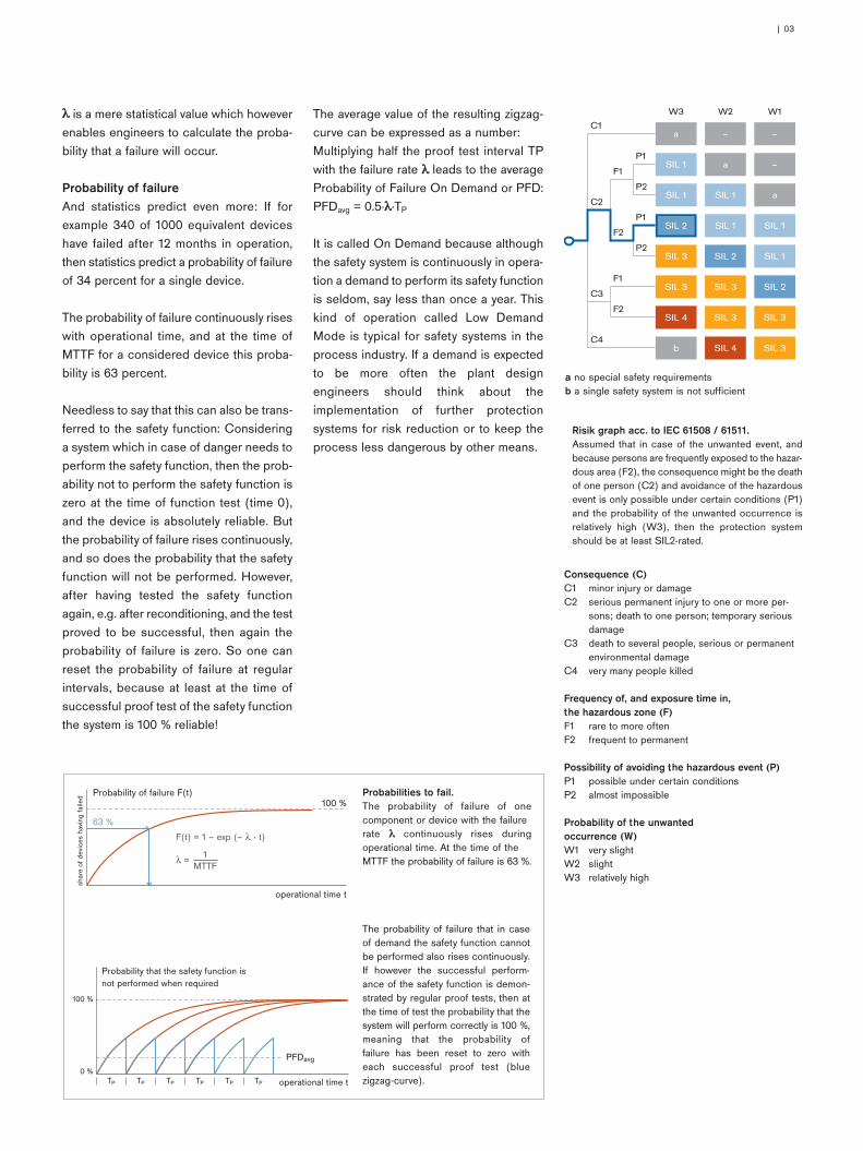
Probabilities to fail.The probability of failure of one component or device with the failure rate λ continuously rises during operational time. At the time of the MTTF the probability of failure is 63 %.
The probability of failure that in caseof demand the safety function cannotbe performed also rises continuously.If however the successful perform-ance of the safety function is demon-strated by regular proof tests, then atthe time of test the probability that thesystem will perform correctly is 100 %,meaning that the probability of failure has been reset to zero witheach successful proof test (bluezigzag-curve).
Probability of failure F(t)
shar
e of
dev
ices
hav
ing
faile
d
operational time t
63 %
100 %
Probability that the safety function is not performed when required
operational time t
PFDavg
100 %
0 %TP TP TP TP TP TP
| 03
Consequence (C)C1 minor injury or damageC2 serious permanent injury to one or more per-
sons; death to one person; temporary seriousdamage
C3 death to several people, serious or permanentenvironmental damage
C4 very many people killed
Frequency of, and exposure time in, the hazardous zone (F)F1 rare to more oftenF2 frequent to permanent
Possibility of avoiding the hazardous event (P)P1 possible under certain conditionsP2 almost impossible
Probability of the unwanted occurrence (W)W1 very slightW2 slightW3 relatively high
––a
W1W2W3
C1
F1
P1
P2
P1
P2
F2
F1
F2
C2
C3
C4
–aSIL 1
aSIL 1SIL 1
SIL 1SIL 1SIL 2
SIL 1SIL 2SIL 3
SIL 2SIL 3SIL 3
SIL 3SIL 3SIL 4
SIL 3SIL 4b
a no special safety requirementsb a single safety system is not sufficient
Risik graph acc. to IEC 61508 / 61511.Assumed that in case of the unwanted event, andbecause persons are frequently exposed to the hazar-dous area (F2), the consequence might be the deathof one person (C2) and avoidance of the hazardousevent is only possible under certain conditions (P1)and the probability of the unwanted occurrence isrelatively high (W3), then the protection systemshould be at least SIL2-rated.
9046256_AB_SIL_Funktionale_Sicherheit_engl:3 16.04.10 08:15 Seite 3
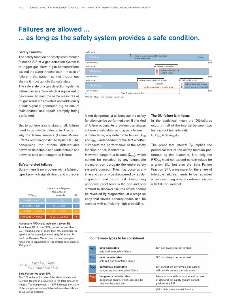
Safety FunctionThe safety function or Safety InstrumentedFunction SIF of a gas detection system isto trigger gas alarm if gas concentrationsexceed the alarm thresholds. If – in case offailure – the system cannot trigger gasalarms it must go into the safe state. The safe state of a gas detection system isdefined as an action which is equivalent togas alarm. At least the same measures asfor gas alarm are activated, and additionallya fault signal is generated e.g. to ensuremaintenance and repair promptly beingperformed.
But to achieve a safe state at all, failuresneed to be reliably detectable. This is why the failure analysis (Failure Modes,Effects and Diagnostic Analysis FMEDA)concerning the effects differentiatesbetween detectable and undetectable andbetween safe and dangerous failures.
Safety-related failuresSurely there is no problem with a failure oftype λSD which signals itself, and moreover
is not dangerous at all because the safetyfunction can be performed even if this kindof failure occurs. As a system can alwaysachieve a safe state as long as a failureis detectable, any detectable failure (λSD
and λDD), independent of the fact whetherit impacts the performance of the safetyfunction or not, is tolerable.However, dangerous failures (λDU), whichcannot be revealed by any diagnosticmeasure, can derogate the entire safetysystem’s concept. They may occur at anytime and can only be discovered by regularinspection and proof test. Performing periodical proof tests is the one and onlymethod to discover failures which cannotbe revealed by diagnostics, at a stage soearly that severe consequences can beavoided with sufficiently high probability.
The DU-failure is in focusIn the statistical mean the DU-failuresoccur at half of the interval between twotests (proof test interval):PFDavg = 0.5·λDU·TP
The proof test interval TP implies the periodical test of the safety function per-formed by the customer. Not only thePFDavg must not exceed certain values fora given SIL, but also the Safe Failure Fraction SFF, a measure for the share oftolerable failures, needs to be regardedwhen designing a safety relevant systemwith SIL-requirement.
safe state
system remains in unsafe state
failure is detected
failure detectedfailure occurs without notice
failure detected during proof test and remedied
failure remedied byinstant repair
failure occurs but system remains in the safe stateS-Failure Safety
DD-Failure
DangerDU-Failure
unsafe state time
MTT
R*
MTT
R*
Proof test interval TP
safe state
safe state
unsafe state
unsafe state time
time
* MTTR = Mean Time To Repair (mostly 8 h)
Failures are allowed …… as long as the safety system provides a safe condition.
Necessary PFDavg to achieve a given SIL.To achieve SIL 2, the PFDavg must be less than0.01, meaning that at more than 100 demands thesystem in the statistical mean may fail once. Forthe Low Demand Mode (one demand per yearmax.) this is equivalent to “the system fails once in 100 years“.
Safe Failure Fraction SFF.The SFF reflects the ratio of the share of safe andtolerable failures in proportion to the total amount offailures. The complement 1 - SFF indicates the shareof the dangerous undetectable failures which shouldbe as low as possible.
PFDavg
system or subsystemfails once of… demands SIL
410 001 … 100 000≥ 0.00001 … < 0.0001
31001 … 10000≥ 0.0001 … < 0.001
2101 … 1000≥ 0.001 … < 0.01
1 11 … 100≥ 0.01 … < 0.1
SD +SFF =
λ SU +λ DDλSD +λ SU +λ DDλ + DUλ
Four failures types to be considered
λSD safe detectable SIF can always be performed safe and detectable failure
λSU safe undetectable SIF can always be performed safe but not detectable failure
λDD dangerous detectable SIF cannot be performed but system dangerous but detectable failure will quickly go into the safe state
λDU dangerous undetectable failure occurs without notice and in case dangerous failure, which can only be of demand the safety system cannot revealed by proof test perform the SIF
(SIF = Safety Instrumented Function)
04 | SAFETY FUNCTION AND SAFETY CHAIN | SIL - SAFETY INTEGRITY LEVEL AND FUNCTIONAL SAFETY
9046256_AB_SIL_Funktionale_Sicherheit_engl:3 16.04.10 08:15 Seite 4
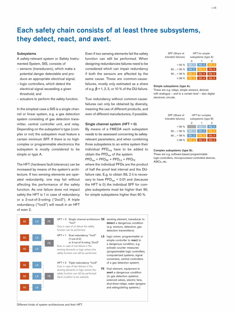
SubsystemsA safety-relevant system or Safety Instru-mented System, SIS, consists of – sensors (transducers), which make a
potential danger detectable and pro-duce an appropriate electrical signal,
– logic controllers, which detect the electrical signal exceeding a giventhreshold, and
– actuators to perform the safety function.
In the simplest case a SIS is a single chan-nel or linear system, e.g. a gas detectionsystem consisting of gas detection trans-mitter, central controller unit, and relay.Depending on the subsystem’s type (com-plex or not) the subsystem must feature acertain minimum SFF. If there is no high-complex or programmable electronics thesubsystem is mostly considered to be simple or type A.
The HFT (hardware fault tolerance) can beincreased by means of the system’s archi-tecture. If two sensing elements are oper-ated redundantly, one may fail withoutaffecting the performance of the safetyfunction. As one failure does not impactsafety the HFT is 1 in case of redundancyor a 2-out-of-3-voting (“2oo3”). A tripleredundancy (“1oo3”) will result in an HFTof even 2.
Even if two sensing elements fail the safetyfunction can still be performed. Whendesigning redundancies failures need to beconsidered which can impair redundancyif both the sensors are affected by thesame cause. These are common-cause-failures, mostly only estimated as a shareof e.g. β = 1, 2, 5, or 10 % of the DU-failure.
True redundancy without common-cause-failures can only be obtained by diversity,meaning the use of different products, andeven of different manufacturers, if possible.
Single channel system (HFT = 0)By means of a FMEDA each subsystemneeds to be assessed concerning its safety-relevant parameters, and when combiningthree subsystems to an entire system theirindividual PFDavg have to be added toobtain the PFDsys of the system:PFDsys = PFDSE + PFDLS + PFDFE
where the individual PFDs are the productof half the proof test interval and the DU-failure rate. E.g. to obtain SIL 2 it is neces-sary to have PFDsys < 0.01 and (becausethe HFT is 0) the individual SFF for com-plex subsystems must be higher than 90,for simple subsystems higher than 60 %.
SE sensing element, transducer todetect a dangerous condition(e.g. sensors, detectors, gasdetection transmitters)
LS logic solver, programmable orsimple controller to react to a dangerous condition, e.g.activate counter measures (programmable logic controllers,computerized systems, signalconverters, central controllersof a gas detection system)
FE final element, equipment toavert a dangerous condition (in gas detection systems: solenoid valves, electric fans,shut-down-relays, water sprayersand extinguishing systems.)
Different kinds of system architectures and their HFT.
Simple subsystems (type A).These are e.g. relays, simple sensors, devices with analogue – and to a certain level – also digitalelectronic circuits.
Complex subsystems (type B).These are e.g. software-based programmable logic-controllers, microprocessor-controlled devices,ASICs, etc.
FE LS SE HFT = 0 Single channel architecture “1oo1”Only in case of no failure the safety function can be performed.
FE
LS SE
LS SE
HFT = 1 Dual redundancy “1oo2” (1-out-of-2) or 2-out-of-3-voting “2oo3”Even in case of one failure in the sensing elements or logic solvers the safety function can still be performed.
FE
LS SE
LS SE
LS SE
HFT = 2 Triple redundancy “1oo3” Even in case of two failures in the sensing elements or logic solvers the safety function can still be performed (fault condition to be realized).
SFF (Share of tolerable failures)
21
HFT for simple subsystems (type A)
0
SIL 4≥ 99 %
SIL 490 … < 99 %
SIL 460 … < 90 %
SIL 3
SIL 4
SIL 4
SIL 3
SIL 2
SIL 3
SIL 3
SIL 2
SIL 1< 60 %
SFF (Share of tolerable failures)
21
HFT for complex subsystems (type B)
0
SIL 4≥ 99 %
SIL 490 … < 99 %
SIL 360 … < 90 %
SIL 2
SIL 4
SIL 3
SIL 2
SIL 1
SIL 3
SIL 2
SIL 1
–< 60 %
Each safety chain consists of at least three subsystems, they detect, react, and avert.
| 05
9046256_AB_SIL_Funktionale_Sicherheit_engl:3 16.04.10 08:15 Seite 5
Dual redundancy (HFT = 1)At first the PFDs of the redundantlydesigned subsystems have to be calculat-ed and to be introduced as PFDSE, PFDLS, or PFDFE into the equationPFDsys = PFDSE + PFDLS + PFDFE.
Because of HFT = 1 the SFF of redundantlydesigned subsystems may be less than 90or 60 % resp. to achieve SIL 2. For non-diverse redundancies always the commoncause failures need to be considered, e.g.as 5 %, meaning β = 0.05.
SIL-conformityWith the declaration of SIL-conformity amanufacturer of subsystems publishes theessential data necessary to design a safetychain by means of subsystems.
Furthermore there are hints included toindicate under which circumstances theSafety Integrity Level is obtained, whichmaintenance actions have to be performed(especially if wear parts are included) andhow to test the safety function during theproof test procedure.
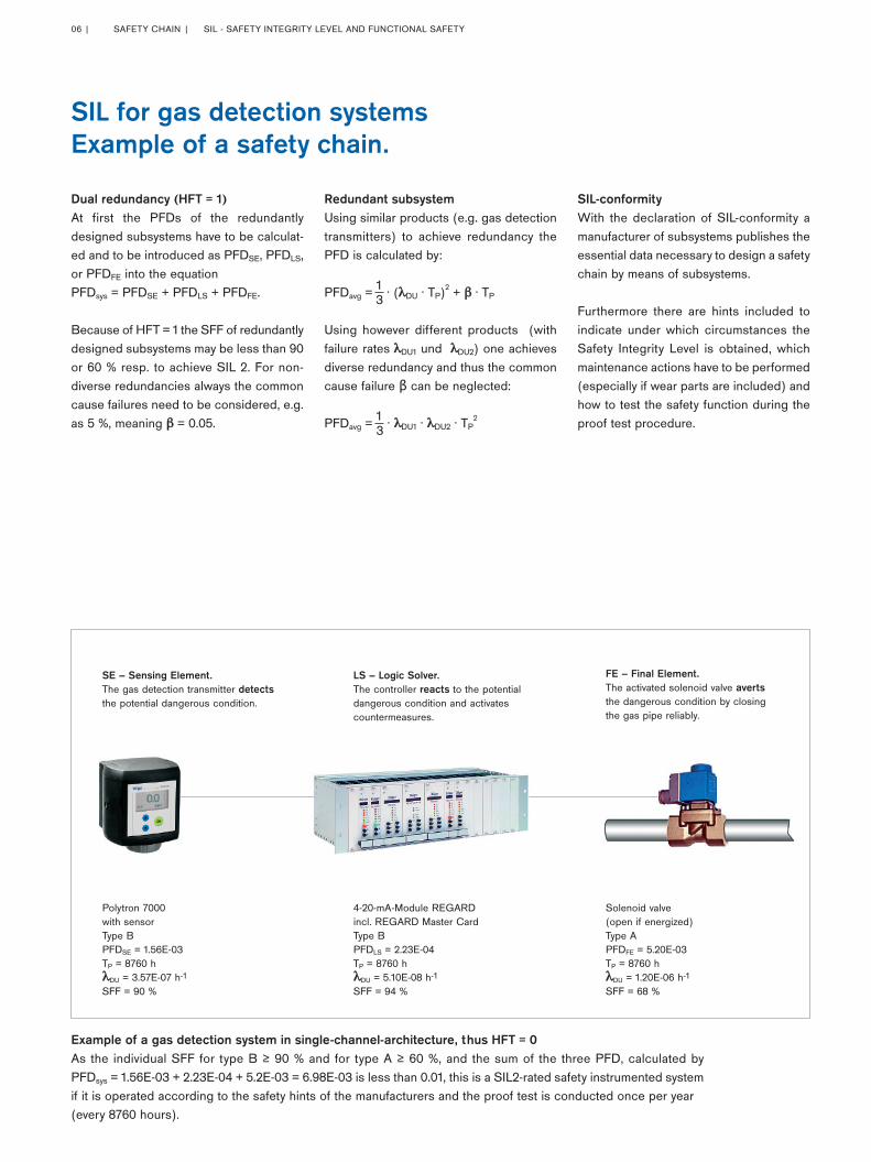
SIL for gas detection systems Example of a safety chain.
Redundant subsystemUsing similar products (e.g. gas detectiontransmitters) to achieve redundancy thePFD is calculated by:
PFDavg = 13. (λDU
. TP)2 + β . TP
Using however different products (withfailure rates�λDU1 und �λDU2) one achievesdiverse redundancy and thus the commoncause failure β can be neglected:
PFDavg = 13. λDU1
. λDU2. TP
2
Example of a gas detection system in single-channel-architecture, thus HFT = 0As the individual SFF for type B ≥ 90 % and for type A ≥ 60 %, and the sum of the three PFD, calculated by PFDsys = 1.56E-03 + 2.23E-04 + 5.2E-03 = 6.98E-03 is less than 0.01, this is a SIL2-rated safety instrumented system if it is operated according to the safety hints of the manufacturers and the proof test is conducted once per year (every 8760 hours).
SE – Sensing Element.The gas detection transmitter detectsthe potential dangerous condition.
Polytron 7000with sensorType BPFDSE = 1.56E-03TP = 8760 hλDU = 3.57E-07 h-1
SFF = 90 %
LS – Logic Solver.The controller reacts to the potentialdangerous condition and activatescountermeasures.
FE – Final Element.The activated solenoid valve avertsthe dangerous condition by closingthe gas pipe reliably.
Solenoid valve (open if energized)Type APFDFE = 5.20E-03TP = 8760 hλDU = 1.20E-06 h-1
SFF = 68 %
4-20-mA-Module REGARDincl. REGARD Master CardType BPFDLS = 2.23E-04TP = 8760 hλDU = 5.10E-08 h-1
SFF = 94 %
06 | SAFETY CHAIN | SIL - SAFETY INTEGRITY LEVEL AND FUNCTIONAL SAFETY
9046256_AB_SIL_Funktionale_Sicherheit_engl:3 16.04.10 08:15 Seite 6
Lifecycle of a SISCommonly a SIS is planned, designed,installed and commissioned by experi-enced system engineers. Just this processrequires a high degree of diligence, docu-mentation depth and verification.
During operation a SIS must be servicedaccording to the manufacturer’s guidelinesgiven in the safety operating manual and tobe put into quasi-new-condition if neces-
sary. Further on the periodically performedproof test of the safety function must beconducted in the compulsory intervals TP,and organizational measures must be metto ensure prompt repair and spare partdelivery in case of need.
Safety Integrity from DrägerNot only is Dräger the manufacturer of sub-systems such as sensors, gas detectiontransmitters and central controllers, but
also Dräger system engineers can designcomplete safety related gas detection systems including documentation, SIL-evidence, installation, commissioning, andmaintenance.
Our system engineers will competently give advice if safety integrity needs to beimplemented in a system’s safety concept.
SIL is not a product’s property but a continuous sustainingprocess - a system’s lifecycle.
DRÄGER-TRANSMITTERS FOR THE USE IN SIL2-RATED SYSTEMS AND THEIR “SIL-PARAMETERS”
Transmitter Measuring principle SFF λDU PFDSE
at HFT = 0 for TP = 1 year
Dräger Polytron IR Type 334 Infrared, for the detection of flammable gases and vapours 96 % 3.00E-08 h-1 1.28E-04
Dräger Polytron 7000 Electrochemical, for toxic gases and oxygen 90 % 3.57E-07 h-1 1.56E-03
Dräger Polytron Pulsar Open-Path infrared, for the detection of flammable gases 92 % 1.09E-07 h-1 4.77E-04
Dräger PIR 7000 Infrared, for the detection of flammable gases and vapours 94 % 4.70E-08 h-1 2.04E-04
Dräger PIR 7200 Infrared, for the detection of carbon dioxide 94 % 4.70E-08 h-1 2.04E-04
| 07
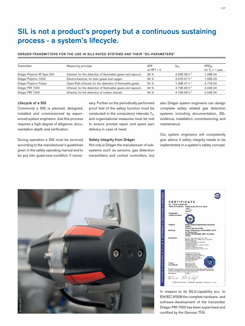
In respect to its SIL2-capability acc. toEN/IEC 61508 the complete hardware- andsoftware-development of the transmitterDräger PIR 7000 has been supervised andcertified by the German TÜV. S
T-11
633-
2008
9046256_AB_SIL_Funktionale_Sicherheit_engl:3 16.04.10 08:15 Seite 7
90 4
6 25
6 |
04.1
0-2
| M
arke
ting
Com
mun
icat
ions
| P
R |
LE
| P
rinte
d in
Ger
man
y |
Chl
orfr
ei –
um
wel
tfreu
ndlic
h |
Änd
erun
gen
vorb
ehal
ten
| ©
201
0 D
räge
r S
afet
y A
G &
Co.
KG
aA
ST-
1220
-200
7
HEADQUARTERSDräger Safety AG & Co. KGaARevalstrasse 123560 Lübeck, Germany
www.draeger.com
GERMANYDräger Safety AG & Co. KGaARevalstrasse 123560 LübeckTel +49 451 882-2794Fax +49 451 882-4991
FRANCEDräger Safety France SAS3c route de la Fédération, BP 8014167025 Strasbourg Cedex 1Tel +33 3 88 40 59 29Fax +33 3 88 40 76 67
SINGAPOREDraeger Safety Asia Pte Ltd67 Ayer Rajah Crescent #06-03Singapore 139950Tel +65 68 72 92 88Fax +65 65 12 19 08
UNITED KINGDOMDraeger Safety UK Ltd.Blyth Riverside Business ParkBlyth, Northumberland NE24 4RGTel +44 1670 352 891Fax +44 1670 544 475
SYSTEM CENTERS
P. R. CHINABeijing Fortune Draeger SafetyEquipment Co., Ltd.A22 Yu An Rd, B Area, Tianzhu Airport Industrial Zone,Shunyi District, Beijing 101300Tel +86 10 80 49 80 00Fax +86 10 80 49 80 05
USADraeger Safety, Inc.505 Julie Rivers, Suite 150Sugar Land, TX 77478Tel +1 281 498 10 82Fax +1 281 498 51 90
9046256_AB_SIL_Funktionale_Sicherheit_engl:3 16.04.10 08:15 Seite 8