functional safety applicable standards technical informationfiles.danfoss.com/documents/functional...
TRANSCRIPT
powersolutions.danfoss.com
MAKING MODERN LIVING POSSIBLE
Technical Information
Functional SafetyAn overview
Technical Information Functional Safety - An overview
L1326395 • Rev AA • Oct 20132
General ........................................................................................................................................................................................ 3Introduction ................................................................................................................................................................................ 3European Union standards structure ................................................................................................................................ 3Designing a safe machine .................................................................................................................................................. 4The process ................................................................................................................................................................................. 4Hazard and Risk Analysis ........................................................................................................................................................ 4
Determine machinery limits ........................................................................................................................................... 4Hazard identification ......................................................................................................................................................... 5Harm sequence .................................................................................................................................................................... 5Risk estimation ..................................................................................................................................................................... 6Risk evaluation ..................................................................................................................................................................... 7Risk reduction ....................................................................................................................................................................... 7
Determining the safety requirement ................................................................................................................................ 9Applying ISO 13849 .......................................................................................................................................................... 10
Severity of injury ......................................................................................................................................................... 10Frequency of exposure ............................................................................................................................................. 10Possibility of avoidance ............................................................................................................................................ 10PLr ..................................................................................................................................................................................... 10
Applying EN 62061 ........................................................................................................................................................... 11SRP/CS architecture ................................................................................................................................................................ 13
Category B ........................................................................................................................................................................... 13Category 1 ........................................................................................................................................................................... 13Category 2 ........................................................................................................................................................................... 14Category 3 ........................................................................................................................................................................... 14Category 4 ........................................................................................................................................................................... 14
System mapping ..................................................................................................................................................................... 15Selecting the components .................................................................................................................................................. 17Validation of the system ....................................................................................................................................................... 18
Applying ISO 13849 .......................................................................................................................................................... 18Applying EN 62061 ...........................................................................................................................................................20
Speaking functional safety .............................................................................................................................................22
Contents
Technical Information Functional Safety - An overview
L1326395 • Rev AA • Oct 2013 3
IntroductionThe purpose of this document is to provide a brief overview of applicable standards in regards to functional safety and to highlight the cooperation needed between OEM customers and Danfoss as sub-supplier.
A safety system has three important key elements; the user(s), the instructions/manuals and the machine itself. This document only shows aspects related to the machine Functional Safety (FS), defined as all the measures aiming to protect the machine operator or bystander from risk during work with and/or around the machine. Not in scope are risks due to other hazards such as electro-magnetic capability (EMC), explosive atmospheres (ATEX) etc. These should, however, be evaluated by the machine manufacturer.
WARNINGThe manufacturer has the sole responsibility for the machine Design, including all three parts of the safety system.
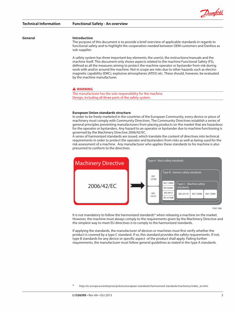
European Union standards structureIn order to be freely marketed in the countries of the European Community, every device or piece of machinery must comply with Community Directives. The Community Directives establish a series of general principles preventing manufacturers from placing products on the market that are hazardous for the operator or bystanders. Any hazard to an operator or bystander due to machine functioning is governed by the Machinery Directive 2006/42/EC.A series of harmonized standards are issued, which translate the content of directives into technical requirements in order to protect the operator and bystanders from risks as well as being used for the risk assessment of a machine. Any manufacturer who applies these standards to his machine is also presumed to conform to the directives.
General
Type A - Bacis safety standards
ISO 12100
ISO 14121
Machinery DirectiveType B - Generic safety standards
ISO 13849
ISO 62061
ISO 4413
IEC 61508
Type C - Machine safety standards
ISO 25119 ISO 15998 ISO 12999
2006/42/EC
P301 568
It is not mandatory to follow the harmonized standards* when releasing a machine on the market. However, the machine must always comply to the requirements given by the Machinery Directive and the simplest way to meet EU directives is to comply to the harmonized standards.
If applying the standards, the manufacturer of devices or machines must first verify whether the product is covered by a type C standard. If so, this standard provides the safety requirements. If not, type B standards for any device or specific aspect of the product shall apply. Failing further requirements, the manufacturer must follow general guidelines as stated in the type A standards.
* http://ec.europa.eu/enterprise/policies/european-standards/harmonised-standards/machinery/index_en.htm
Technical Information Functional Safety - An overview
L1326395 • Rev AA • Oct 20134
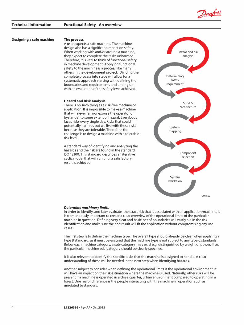
Designing a safe machine The processA user expects a safe machine. The machine design also has a significant impact on safety. When working with and/or around a machine, they expect to complete the tasks unharmed. Therefore, it is vital to think of functional safety in machine development. Applying functional safety to the machine is a process like many others in the development project. Dividing the complete process into steps will allow for a systematic approach starting with defining the boundaries and requirements and ending up with an evaluation of the safety level achieved.
Hazard and Risk AnalysisThere is no such thing as a risk-free machine or application. It is impossible to make a machine that will never fail nor expose the operator or bystander to some extent of hazard. Everybody faces risks every single day. Risks that could potentially harm us but we live with these risks because they are tolerable. Therefore, the challenge is to design a machine with a tolerable risk level.
A standard way of identifying and analyzing the hazards and the risk are found in the standard ISO 12100. This standard describes an iterative cyclic model that will run until a satisfactory result is achieved.
Hazard and riskanalysis
SRP/CSarchitecture
Componentselection
Determiningsafety
requirement
System mapping
Systemvalidation
P301 569P301 569
Determine machinery limitsIn order to identify, and later evaluate the exact risk that is associated with an application/machine, it is tremendously important to create a clear overview of the operational limits of the particular machine in question. Defining very clear and basicl set of boundaries will vastly aid in the risk identification and make sure the end result will fit the application without compromising any use cases.
The first step is to define the machine type. The overall type should already be clear when applying a type B standard, as it must be ensured that the machine type is not subject to any type C standards. Below each machine category, a sub-category may exist e.g. distinguished by weight or power. If so, the particular machine sub-category should be clearly specified.
It is also relevant to identify the specific tasks that the machine is designed to handle. A clear understanding of these will be needed in the next step when identifying hazards.
Another subject to consider when defining the operational limits is the operational environment. It will have an impact on the risk estimation where the machine is used. Naturally, other risks will be present if a machine is operated in a close-quarter, urban environment compared to operating in a forest. One major difference is the people interacting with the machine in operation such as unrelated bystanders.
Technical Information Functional Safety - An overview
L1326395 • Rev AA • Oct 2013 5
Designing a safe machine(continued)
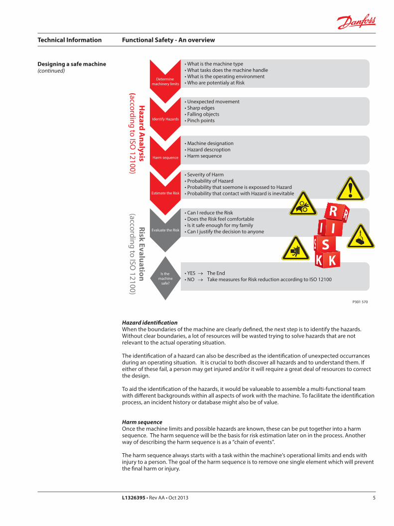
Determine machinery limits
• What is the machine type• What tasks does the machine handle• What is the operating environment• Who are potentialy at Risk
Identify Hazards
• Unexpected movement• Sharp edges• Falling objects• Pinch points
Harm sequence
• Machine designation• Hazard descroption• Harm sequence
Estimate the Risk
• Severity of Harm• Probability of Hazard• Probability that soemone is expossed to Hazard• Probability that contact with Hazard is inevitable
Evaluate the Risk
• Can I reduce the Risk• Does the Risk feel comfortable• Is it safe enough for my family• Can I justify the decision to anyone
Is the machine
safe?
• YES → The End• NO → Take measures for Risk reduction according to ISO 12100
Hazard A
nalysis(according to ISO
12100)Risk Evaluation
(according to ISO 12100)
P301 570
S
Hazard identificationWhen the boundaries of the machine are clearly defined, the next step is to identify the hazards. Without clear boundaries, a lot of resources will be wasted trying to solve hazards that are not relevant to the actual operating situation.
The identification of a hazard can also be described as the identification of unexpected occurrances during an operating situation. It is crucial to both discover all hazards and to understand them. If either of these fail, a person may get injured and/or it will require a great deal of resources to correct the design.
To aid the identification of the hazards, it would be valueable to assemble a multi-functional team with different backgrounds within all aspects of work with the machine. To facilitate the identification process, an incident history or database might also be of value.
Harm sequenceOnce the machine limits and possible hazards are known, these can be put together into a harm sequence. The harm sequence will be the basis for risk estimation later on in the process. Another way of describing the harm sequence is as a “chain of events”.
The harm sequence always starts with a task within the machine’s operational limits and ends with injury to a person. The goal of the harm sequence is to remove one single element which will prevent the final harm or injury.
Technical Information Functional Safety - An overview
L1326395 • Rev AA • Oct 20136
S
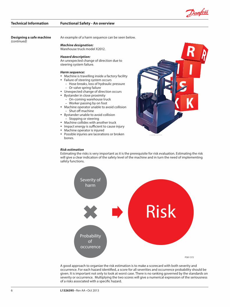
An example of a harm sequence can be seen below.Designing a safe machine(continued)
Severity ofharm
Probabilityof
occurence
Risk
P301 572
Machine designation:Warehouse truck model X2012.
Hazard description:An unexpected change of direction due to steering system failure.
Harm sequence: y Machine is travelling inside a factory facility y Failure of steering system occurs
– Hose breaks, loss of hydraulic pressure – Or valve spring failure
y Unexpected change of direction occurs y Bystander in close proximity
– On-coming warehouse truck – Worker passing by on foot
y Machine operator unable to avoid collision – Shut off machine
y Bystander unable to avoid collision – Stopping or steering
y Machine collides with another truck y Impact energy is sufficient to cause injury y Machine operator is injured y Possible injuries are lacerations or broken
bones.
Risk estimationEstimating the risks is very important as it is the prerequisite for risk evaluation. Estimating the risk will give a clear indication of the safety level of the machine and in turn the need of implementing safety functions.
A good approach to organize the risk estimation is to make a scorecard with both severity and occurrence. For each hazard identified, a score for all severities and occurrence probability should be given. It is important not only to look at worst case. There is no ranking governed by the standards on severity or occurrence. Multiplying the two scores will give a numerical expression of the seriousness of a risks associated with a specific hazard.
Technical Information Functional Safety - An overview
L1326395 • Rev AA • Oct 2013 7
Risk evaluationThe risk evaluation is the point in the process where the safety level of the machine and the possible need for safety features to reduce risk are decided. By completing the risk evaluation, a guide to risk reduction is made.
For each risk identified and scored in the risk estimation, an evaluation must be performed. The purpose of the evaluation is to decide if the current safety level are sufficient to the machine builder. In other words, the risk evaluation determines if the risk present is tolerable. It is important to keep in mind that there is no such thing as a risk-free machine or application. The goal is to design and build a machine which only has tolerable risks.
If the risk is tolerable by the way the machine is designed, the hazard and risk analysis is complete and the machine/application is compliant with all regulations and conforms with the machinery directive.
If the risk is not tolerable, measures for risk reduction must be taken.
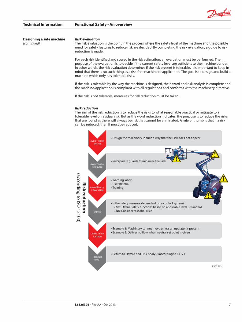
Risk reductionThe aim of the risk reduction is to reduce the risks to what reasonable practical or mitigate to a tolerable level of residual risk. But as the word reduction indicates, the purpose is to reduce the risks that are found as there will always be risk that cannot be eliminated. A rule of thumb is that if a risk can be reduced, then it must be reduced.
Designing a safe machine(continued)
Avoid Risk by design
• Design the machinery in such a way that the Risk does not appear
Avoid Risk by safeguard
• Incorporate guards to minimize the Risk
Avioid Risk by information
• Warning labels• User manual• Training
SRP/CS
• Is the safety measure dependant on a control system? • Yes: De�ne safety functions based on applicable level B standard • No: Consider resedual Risks
De�ne safety function
• Example 1: Machinery cannot move unless an operator is present• Example 2: Deliver no �ow when neutral set point is given
Resedual Risks?
• Return to Hazard and Risk Analysis according to 14121
Risk reduction(according to ISO
12100)
P301 573
Technical Information Functional Safety - An overview
L1326395 • Rev AA • Oct 20138
The optimum way of reducing a risk, is to design the machine in such a way that the risk cannot be visible. However, this is not always possible if this will limit or conflict with machine operational limits. The commercial realities of putting a machine on the market also have a significant impact on the machine design and cost of same. Examples of risk reduction by design are openings made too small for human limbs to enter or rotating spoke-discs replaced by plate-discs.
Another way of reducing risks is to incorporate safe guards on the machine. Safe guards are not seen as a way to design out the risk, but as a separate way of reducing them. Examples of safe guards are light curtains, two hand control and system interlocks.
The last way of reducing the risk is to inform the user about them. This covers training, manuals, etc. It is important to have in mind that training the user will only affect the probability of harm to the user. Bystanders and similar will not be effected by this and the probability of harm will therefore not decrease much. Examples of information could bewarning labels, display information or use cases in manuals.
This document does not cover Information on use. Please refer to DIN 4844-2 for warning symbols
When the risk reduction measures are identified, their method of implementation must be evaluated. If the risk reduction measure is realized by a control system, a safety function of each risk must be defined. The activation of the safety function will result in a defined safe state. A failure to perform the safety function is equal to an increased risk. A safety function is not part of a machine/application standard operation, meaning that in case the safety function fails, the machine/application can still operate but with an increased risk.
The process of reducing the risks is repetitive. Whenever a measure for risk reduction has been decided and implemented it must be evaluated if this addition or design change to the machine/application has caused new risks not present before. If so, one must return to hazard identification and repeat the process from there.
Designing a safe machine(continued)
Technical Information Functional Safety - An overview
L1326395 • Rev AA • Oct 2013 9
Designing a safe machine(continued)
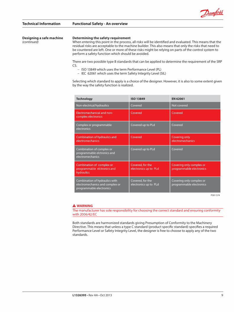
Determining the safety requirementWhen entering this point in the process, all risks will be identified and evaluated. This means that the residual risks are acceptable to the machine builder. This also means that only the risks that need to be countered are left. One or more of these risks might be relying on parts of the control system to perform a safety function which should be avoided.
There are two possible type B standards that can be applied to determine the requirement of the SRP CS.
– ISO 13849 which uses the term Performance Level (PL) – IEC 62061 which uses the term Safety Integrity Level (SIL)
Selecting which standard to apply is a choice of the designer. However, it is also to some extent given by the way the safety function is realized.
Technology ISO 13849 EN 62061
Non-electrical/hydraulics Covered Not covered
Electromechanical and non-complex electronics
Covered Covered
Complex or programmableelectronics
Covered up to PLd Covered
Combination of hydraulics and electromechanics
Covered Covering onlyelectromechanics
Combination of complex or programmable elctronics and electromechanics
Covered up to PLd Covered
Combination of complex or programmable elctronics and hydraulics
Covered, for the electronics up to PLd
Covering only complex or programmable electronics
Combination of hydraulics with electromechanics and complex or programmable electronics
Covered, for the electronics up to PLd
Covering only complex or programmable electronics
P301 574
WARNINGThe manufacturer has sole responsibility for choosing the correct standard and ensuring conformity with 2006/42/EC
Both standards are harmonized standards giving Presumption of Conformity to the Machinery Directive. This means that unless a type C standard (product specific standard) specifies a required Performance Level or Safety Integrity Level, the designer is free to choose to apply any of the two standards.
Technical Information Functional Safety - An overview
L1326395 • Rev AA • Oct 201310
Designing a safe machine(continued)
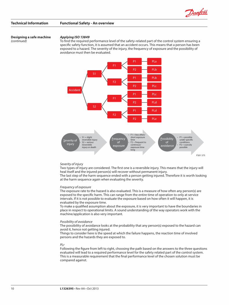
Applying ISO 13849To find the required performance level of the safety-related part of the control system ensuring a specific safety function, it is assumed that an accident occurs. This means that a person has been exposed to a hazard. The severity of the injury, the frequency of exposure and the possibility of avoidance must then be evaluated.
S1
F1P1 PLa
P2 PLb
F2P1 PLb
P2 PLc
S2
F1P1 PLc
P2 PLd
F2P1 PLd
P2 PLe
• S1 = slight reversible injury• S2 = serious ireversible injury or death
Severity of injury
• F1 = less often/ short exposure time• F2 = frequent to continous/ exposure time long
Frequency of
exposure
• P1 = possible under speci�c conditions• P2 = scarcely possible
Possibility of
avoidance
P301 575
Accident
Severity of injuryTwo types of injury are considered. The first one is a reversible injury. This means that the injury will heal itself and the injured person(s) will recover without permanent injury.The last step of the harm sequence ended with a person getting injured. Therefore it is worth looking at the harm sequence again when evaluating the severity.
Frequency of exposureThe exposure rate to the hazard is also evaluated. This is a measure of how often any person(s) are exposed to the specific harm. This can range from the entire time of operation to only at service intervals. If it is not possible to evaluate the exposure based on how often it will happen, it is evaluated by the exposure time.To make a qualified assumption about the exposure, it is very important to have the boundaries in place in respect to operational limits. A sound understanding of the way operators work with the machine/application is also very important.
Possibility of avoidanceThe possibility of avoidance looks at the probability that any person(s) exposed to the hazard can avoid it, hence not getting injured. Things to consider here is the speed at which the failure happens, the reaction time of involved persons and the hazards they are exposed to.
PLrFollowing the figure from left to right, choosing the path based on the answers to the three questions evaluated will lead to a required performance level for the safety related part of the control system. This is a measurable requirement that the final performance level of the chosen solution must be compared against.
Technical Information Functional Safety - An overview
L1326395 • Rev AA • Oct 2013 11
Designing a safe machine(continued)
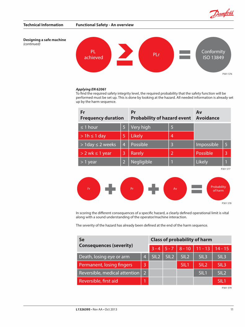
PL achieved PLr Conformity
ISO 13849
P301 576
Applying EN 62061To find the required safety integrity level, the required probability that the safety function will be performed must be set up. This is done by looking at the hazard. All needed information is already set up by the harm sequence.
FrFrequency duration
PrProbability of hazard event
AvAvoidance
≤ 1 hour 5 Very high 5
> 1h ≤ 1 day 5 Likely 4
> 1day ≤ 2 weeks 4 Possible 3 Impossible 5
> 2 wk ≤ 1 year 3 Rarely 2 Possible 3
> 1 year 2 Negligible 1 Likely 1P301 577
Fr Pr Av Probabilityof harm
P301 578
In scoring the different consequences of a specific hazard, a clearly defined operational limit is vital along with a sound understanding of the operator/machine interaction.
The severity of the hazard has already been defined at the end of the harm sequence.
SeConsequences (severity)
Class of probability of harm
3 - 4 5 - 7 8 - 10 11 - 13 14 - 15
Death, losing eye or arm 4 SIL2 SIL2 SIL2 SIL3 SIL3
Permanent, losing �ngers 3 SIL1 SIL2 SIL3
Reversible, medical attention 2 SIL1 SIL2
Reversible, �rst aid 1 SIL1P301 579
Technical Information Functional Safety - An overview
L1326395 • Rev AA • Oct 201312
Designing a safe machine(continued)
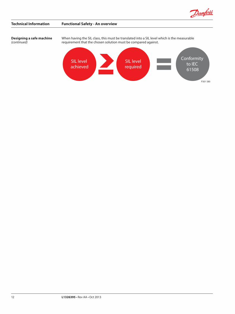
When having the SIL class, this must be translated into a SIL level which is the measurable requirement that the chosen solution must be compared against.
SIL level achieved
SIL levelrequired
Conformity to IEC 61508
P301 580
Technical Information Functional Safety - An overview
L1326395 • Rev AA • Oct 2013 13
Designing a safe machine(continued)
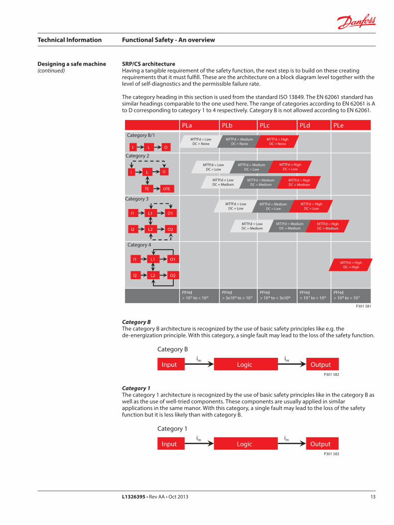
SRP/CS architectureHaving a tangible requirement of the safety function, the next step is to build on these creating requirements that it must fulfill. These are the architecture on a block diagram level together with the level of self-diagnostics and the permissible failure rate.
The category heading in this section is used from the standard ISO 13849. The EN 62061 standard has similar headings comparable to the one used here. The range of categories according to EN 62061 is A to D corresponding to category 1 to 4 respectively. Category B is not allowed according to EN 62061.
PLa PLb PLc PLd PLe
PFHd > 10-5 to < 10-4
PFHd > 3x10⁻⁶ to < 10-5
PFHd > 10-6 to < 3x10⁻⁶
PFHd > 10-7 to < 10-6
PFHd > 10-8 to < 10-7
Category B/1
I O L
MTTFd = Medium DC = None
MTTFd = Low DC = None
MTTFd = High DC = None
I O
TE OTE
Category 2
L
MTTFd = MediumDC = Low
MTTFd = LowDC = Low
MTTFd = HighDC = Low
MTTFd = Medium DC = Medium
MTTFd = Low DC = Medium
MTTFd = High DC = Medium
Category 3
I1 O1 L1
I2 O2 L2
MTTFd = Medium DC = Low
MTTFd = Low DC = Low
MTTFd = High DC = Low
MTTFd = Medium DC = Medium
MTTFd = Low DC = Medium
MTTFd = High DC = Medium
MTTFd = High DC = High
Category 4
I1 O1L1
I2 O2 L2
P301 581
Category BThe category B architecture is recognized by the use of basic safety principles like e.g. the de-energization principle. With this category, a single fault may lead to the loss of the safety function.
Category 1The category 1 architecture is recognized by the use of basic safety principles like in the category B as well as the use of well-tried components. These components are usually applied in similar applications in the same manor. With this category, a single fault may lead to the loss of the safety function but it is less likely than with category B.
Input Outputim im
Logic
Category B
P301 582
Input Outputim im
Logic
Category 1
P301 583
Technical Information Functional Safety - An overview
L1326395 • Rev AA • Oct 201314
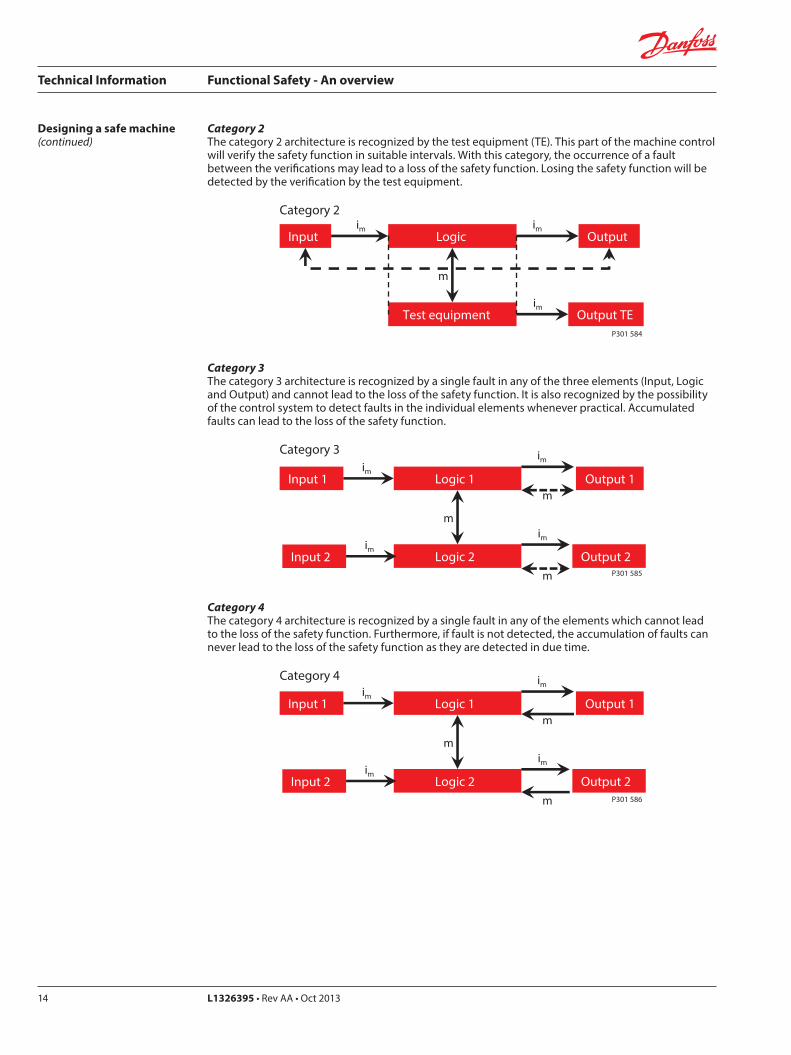
Category 2The category 2 architecture is recognized by the test equipment (TE). This part of the machine control will verify the safety function in suitable intervals. With this category, the occurrence of a fault between the verifications may lead to a loss of the safety function. Losing the safety function will be detected by the verification by the test equipment.
Category 3The category 3 architecture is recognized by a single fault in any of the three elements (Input, Logic and Output) and cannot lead to the loss of the safety function. It is also recognized by the possibility of the control system to detect faults in the individual elements whenever practical. Accumulated faults can lead to the loss of the safety function.
Category 4The category 4 architecture is recognized by a single fault in any of the elements which cannot lead to the loss of the safety function. Furthermore, if fault is not detected, the accumulation of faults can never lead to the loss of the safety function as they are detected in due time.
Designing a safe machine(continued)
Input Logic Outputim im
Test equipment
m
Output TEim
Category 2
P301 584
Input 1 Logic 1 Output 1im
im
Logic 2
m im
Category 3
Input 2im
Output 2
m
m P301 585
Input 1 Logic 1 Output 1im
im
Logic 2
m im
Category 4
Input 2im
Output 2
m
m P301 586
Technical Information Functional Safety - An overview
L1326395 • Rev AA • Oct 2013 15
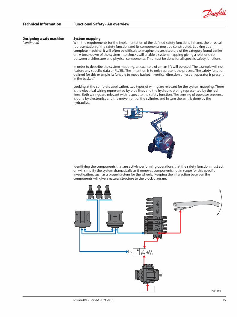
Identifying the components that are activly performing operations that the safety function must act on will simplify the system dramatically as it removes components not in scope for this specific investigation, such as a propel system for the wheels. Keeping the interaction between the components will give a natural structure to the block diagram.
Designing a safe machine(continued)
System mappingWith the requirements for the implementation of the defined safety functions in hand, the physical representation of the safety function and its components must be constructed. Looking at a complete machine, it will often be difficult to imagine the architecture of the category found earlier on. A breakdown of the system into chucks will enable a system mapping giving a relationship between architecture and physical components. This must be done for all specific safety functions.
In order to describe the system mapping, an example of a man lift will be used. The example will not feature any specific data or PL/SIL. The intention is to only represent the process. The safety function defined for this example is: “unable to move basket in vertical direction unless an operator is present in the basket.”
Looking at the complete application, two types of wiring are relevant for the system mapping. There is the electrical wiring represented by blue lines and the hydraulic piping represented by the red lines. Both wirings are relevant with respect to the safety function. The sensing of operator presence is done by electronics and the movement of the cylinder, and in turn the arm, is done by the hydraulics.
HIC
H
IC
HIC
val
ve
P301 594
Technical Information Functional Safety - An overview
L1326395 • Rev AA • Oct 201316
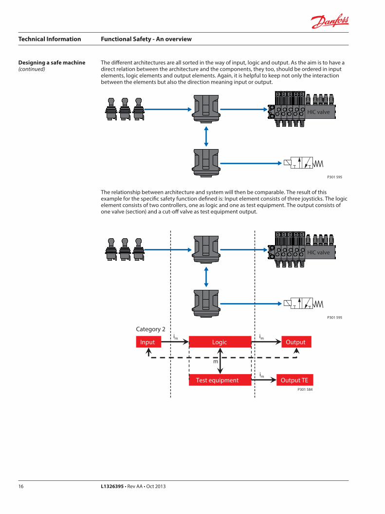
The different architectures are all sorted in the way of input, logic and output. As the aim is to have a direct relation between the architecture and the components, they too, should be ordered in input elements, logic elements and output elements. Again, it is helpful to keep not only the interaction between the elements but also the direction meaning input or output.
The relationship between architecture and system will then be comparable. The result of this example for the specific safety function defined is: Input element consists of three joysticks. The logic element consists of two controllers, one as logic and one as test equipment. The output consists of one valve (section) and a cut-off valve as test equipment output.
Designing a safe machine(continued)
HIC HIC HIC valve
P301 595
HIC HIC HIC valve
P301 595
Input Logic Outputim im
Test equipment
m
Output TEim
Category 2
P301 584
Technical Information Functional Safety - An overview
L1326395 • Rev AA • Oct 2013 17
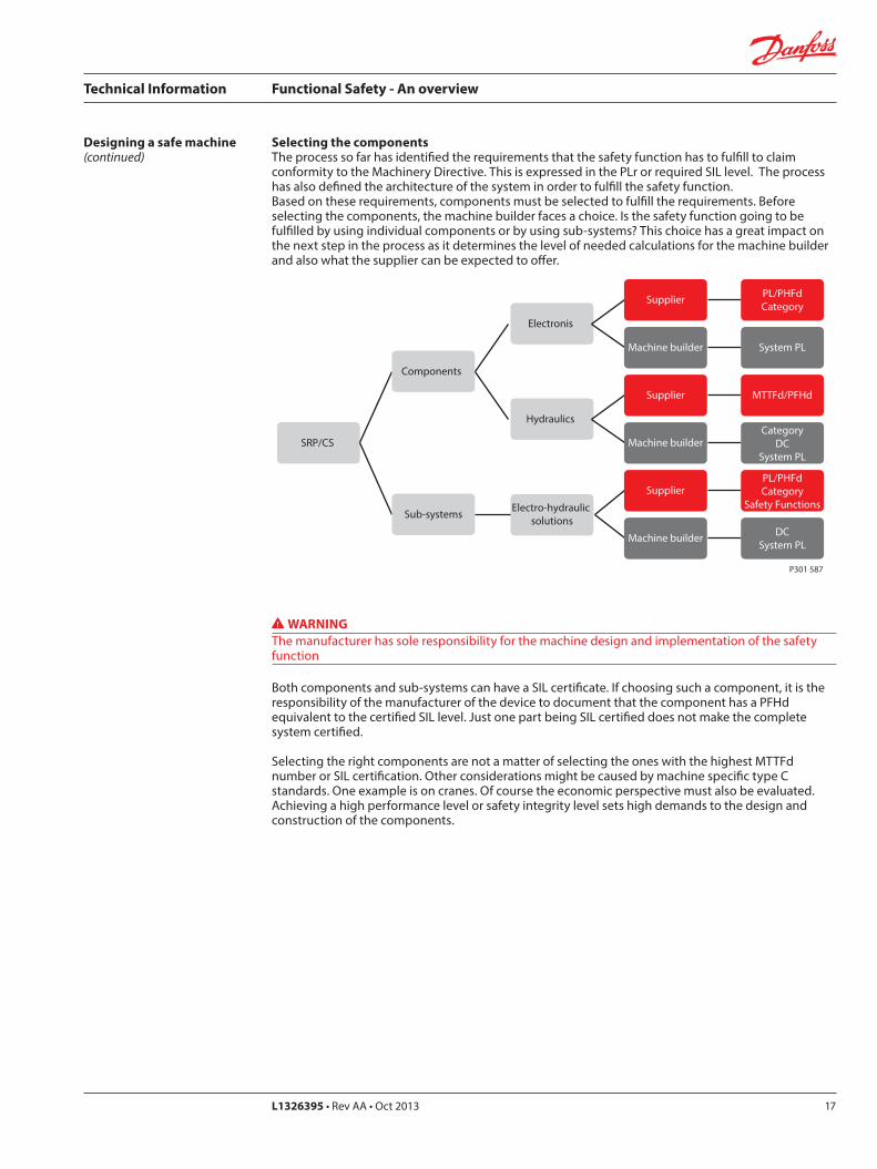
Selecting the componentsThe process so far has identified the requirements that the safety function has to fulfill to claim conformity to the Machinery Directive. This is expressed in the PLr or required SIL level. The process has also defined the architecture of the system in order to fulfill the safety function. Based on these requirements, components must be selected to fulfill the requirements. Before selecting the components, the machine builder faces a choice. Is the safety function going to be fulfilled by using individual components or by using sub-systems? This choice has a great impact on the next step in the process as it determines the level of needed calculations for the machine builder and also what the supplier can be expected to offer.
Designing a safe machine(continued)
SRP/CS
Components
Electronis
Supplier PL/PHFdCategory
Machine builder System PL
Hydraulics
Supplier MTTFd/PFHd
Machine builderCategory
DCSystem PL
Sub-systems Electro-hydraulic solutions
SupplierPL/PHFdCategory
Safety Functions
Machine builder DCSystem PL
P301 587
WARNINGThe manufacturer has sole responsibility for the machine design and implementation of the safety function
Both components and sub-systems can have a SIL certificate. If choosing such a component, it is the responsibility of the manufacturer of the device to document that the component has a PFHd equivalent to the certified SIL level. Just one part being SIL certified does not make the complete system certified.
Selecting the right components are not a matter of selecting the ones with the highest MTTFd number or SIL certification. Other considerations might be caused by machine specific type C standards. One example is on cranes. Of course the economic perspective must also be evaluated. Achieving a high performance level or safety integrity level sets high demands to the design and construction of the components.
Technical Information Functional Safety - An overview
L1326395 • Rev AA • Oct 201318
Channel1
Channel2
P301 588
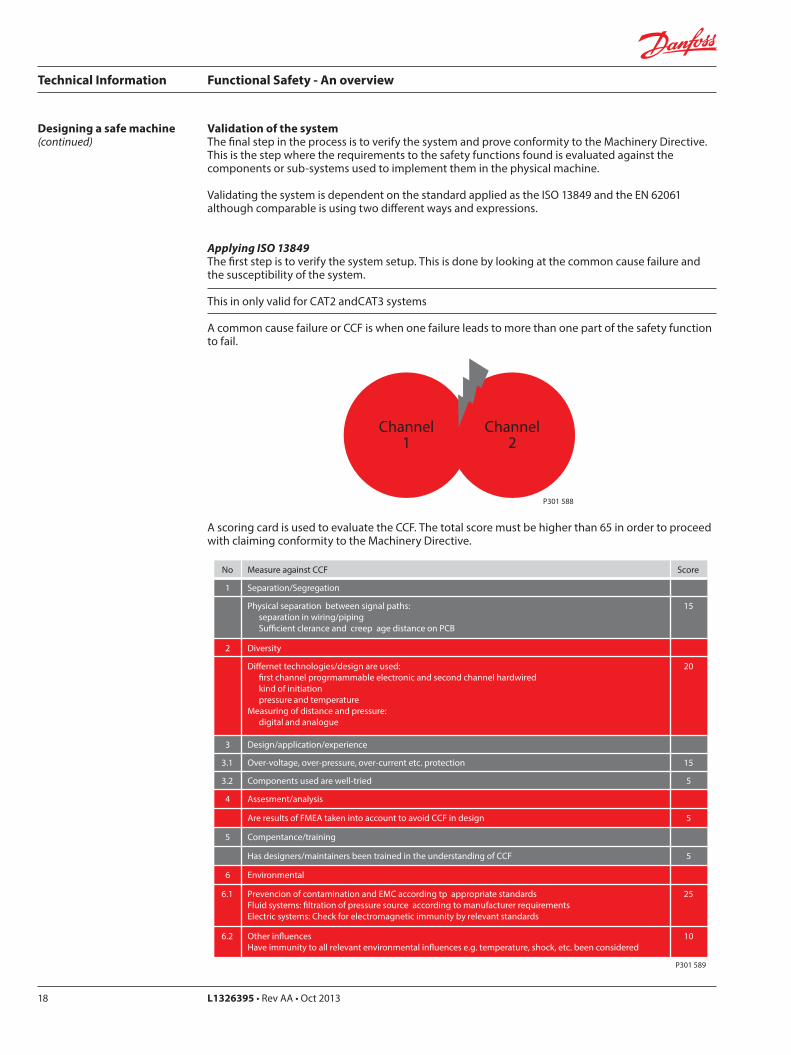
No Measure against CCF Score
1 Separation/Segregation
Physical separation between signal paths: separation in wiring/piping Su�cient clerance and creep age distance on PCB
15
2 Diversity
Di�ernet technologies/design are used: �rst channel progrmammable electronic and second channel hardwired kind of initiation pressure and temperatureMeasuring of distance and pressure: digital and analogue
20
3 Design/application/experience
3.1 Over-voltage, over-pressure, over-current etc. protection 15
3.2 Components used are well-tried 5
4 Assesment/analysis
Are results of FMEA taken into account to avoid CCF in design 5
5 Compentance/training
Has designers/maintainers been trained in the understanding of CCF 5
6 Environmental
6.1 Prevencion of contamination and EMC according tp appropriate standardsFluid systems: �ltration of pressure source according to manufacturer requirementsElectric systems: Check for electromagnetic immunity by relevant standards
25
6.2 Other in�uencesHave immunity to all relevant environmental in�uences e.g. temperature, shock, etc. been considered
10
P301 589
Designing a safe machine(continued)
Validation of the systemThe final step in the process is to verify the system and prove conformity to the Machinery Directive. This is the step where the requirements to the safety functions found is evaluated against the components or sub-systems used to implement them in the physical machine.
Validating the system is dependent on the standard applied as the ISO 13849 and the EN 62061 although comparable is using two different ways and expressions.
Applying ISO 13849The first step is to verify the system setup. This is done by looking at the common cause failure and the susceptibility of the system.
This in only valid for CAT2 andCAT3 systems
A common cause failure or CCF is when one failure leads to more than one part of the safety function to fail.
A scoring card is used to evaluate the CCF. The total score must be higher than 65 in order to proceed with claiming conformity to the Machinery Directive.
Technical Information Functional Safety - An overview
L1326395 • Rev AA • Oct 2013 19
Designing a safe machine(continued)
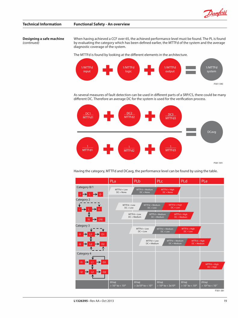
When having achieved a CCF over 65, the achieved performance level must be found. The PL is found by evaluating the category which has been defined earlier, the MTTFd of the system and the average diagnostic coverage of the system.
The MTTFd is found by looking at the different elements in the architecture.
As several measures of fault detection can be used in different parts of a SRP/CS, there could be many different DC. Therefore an average DC for the system is used for the verification process.
Having the category, MTTFd and DCavg, the performance level can be found by using the table.
1/MTTFdinput
1/MTTFdlogic
1/MTTFdoutput
1/MTTFdsystem
P301 590
DC1 MTTFd1
DC2 MTTFd2
DC3 MTTFd3
DCavg
1 MTTFd1
1 MTTFd2
1 MTTFd3
P301 591
PLa PLb PLc PLd PLe
PFHd > 10-5 to < 10-4
PFHd > 3x10⁻⁶ to < 10-5
PFHd > 10-6 to < 3x10⁻⁶
PFHd > 10-7 to < 10-6
PFHd > 10-8 to < 10-7
Category B/1
I O L
MTTFd = Medium DC = None
MTTFd = Low DC = None
MTTFd = High DC = None
I O
TE OTE
Category 2
L
MTTFd = MediumDC = Low
MTTFd = LowDC = Low
MTTFd = HighDC = Low
MTTFd = Medium DC = Medium
MTTFd = Low DC = Medium
MTTFd = High DC = Medium
Category 3
I1 O1 L1
I2 O2 L2
MTTFd = Medium DC = Low
MTTFd = Low DC = Low
MTTFd = High DC = Low
MTTFd = Medium DC = Medium
MTTFd = Low DC = Medium
MTTFd = High DC = Medium
MTTFd = High DC = High
Category 4
I1 O1L1
I2 O2 L2
P301 581
Technical Information Functional Safety - An overview
L1326395 • Rev AA • Oct 201320
Looking back at the step determining the safety requirement, a required performance level was defined. Based on achieved performance level and the required performance level, conformity to the Machinery Directive can now be proven. This must be done for each safety function.
Designing a safe machine(continued)
PL achieved PLr Conformity
ISO 13849
P301 576
This document only covers the functional safety part of the Machinery Directive. Conformity to the functional safety part does not mean conformity to the complete Machinery Directive. Other standards may apply.
When proving the conformity, it is very important to remember that this is not a verbal process performed at meetings. All steps in the process, thoughts, prerequisites, considerations and choices must be carefully documented.
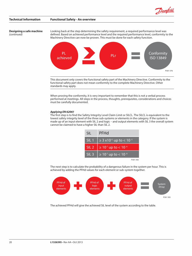
Applying EN 62061The first step is to find the Safety Integrity Level Claim Limit or SILCL. The SILCL is equivalent to the lowest safety integrity level of the three sub-systems or elements in the category. If the system is made up of an input element with SIL 2 and logic – and output elements with SIL 3 the overall system cannot be claimed to have a higher SIL than SIL 2.
SIL PFHd
SIL 1 ≥ 3 x10⁻⁶ up to < 10 -5
SIL 2 ≥ 10-7 up to < 10 -6
SIL 3 ≥ 10-7 up to < 10 -8
P301 592
The next step is to calculate the probability of a dangerous failure in the system per hour. This is achieved by adding the PFHd values for each element or sub-system together.
PFHd of input
elements
PFHd of logic
elements
PFHd of output
elements
SystemPFHd
P301 593
The achieved PFHd will give the achieved SIL level of the system according to the table.
Technical Information Functional Safety - An overview
L1326395 • Rev AA • Oct 2013 21
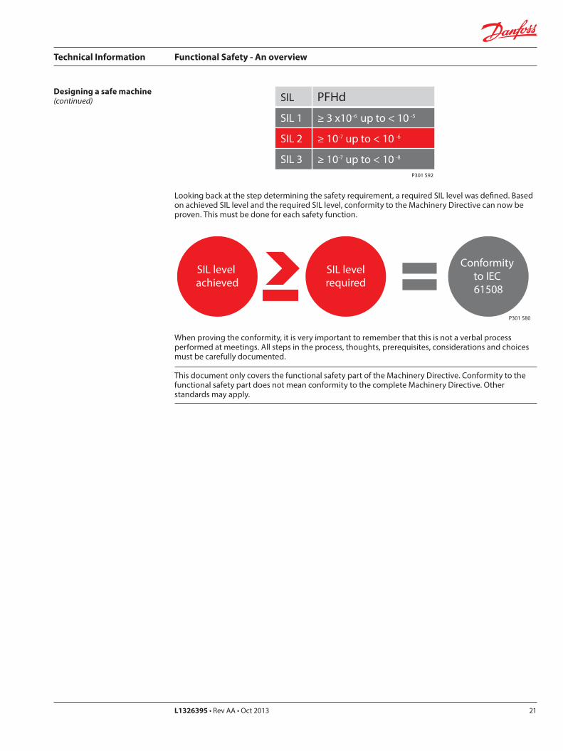
Designing a safe machine(continued) SIL PFHd
SIL 1 ≥ 3 x10⁻⁶ up to < 10 -5
SIL 2 ≥ 10-7 up to < 10 -6
SIL 3 ≥ 10-7 up to < 10 -8
P301 592
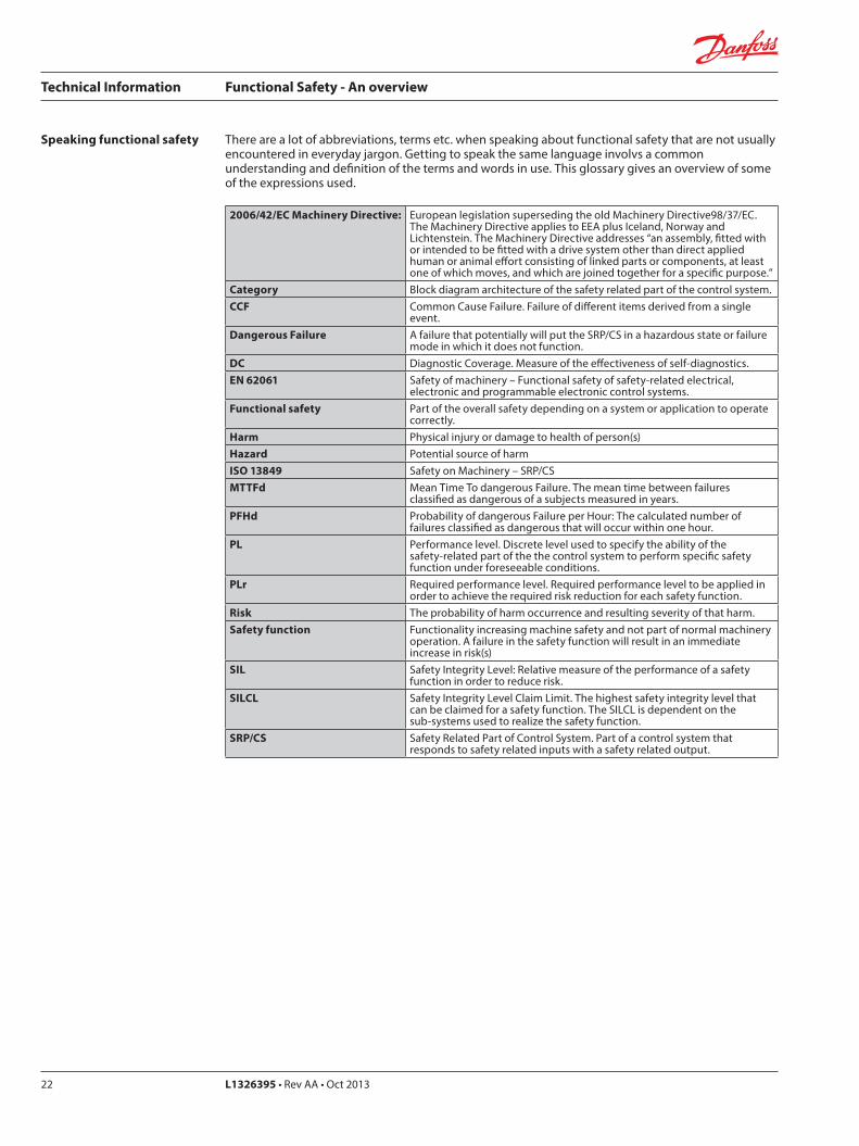
Looking back at the step determining the safety requirement, a required SIL level was defined. Based on achieved SIL level and the required SIL level, conformity to the Machinery Directive can now be proven. This must be done for each safety function.
SIL level achieved
SIL levelrequired
Conformity to IEC 61508
P301 580
When proving the conformity, it is very important to remember that this is not a verbal process performed at meetings. All steps in the process, thoughts, prerequisites, considerations and choices must be carefully documented.
This document only covers the functional safety part of the Machinery Directive. Conformity to the functional safety part does not mean conformity to the complete Machinery Directive. Other standards may apply.
Technical Information Functional Safety - An overview
L1326395 • Rev AA • Oct 201322
Speaking functional safety There are a lot of abbreviations, terms etc. when speaking about functional safety that are not usually encountered in everyday jargon. Getting to speak the same language involvs a common understanding and definition of the terms and words in use. This glossary gives an overview of some of the expressions used.
2006/42/EC Machinery Directive: European legislation superseding the old Machinery Directive98/37/EC. The Machinery Directive applies to EEA plus Iceland, Norway and Lichtenstein. The Machinery Directive addresses “an assembly, fitted with or intended to be fitted with a drive system other than direct applied human or animal effort consisting of linked parts or components, at least one of which moves, and which are joined together for a specific purpose.”
Category Block diagram architecture of the safety related part of the control system. CCF Common Cause Failure. Failure of different items derived from a single
event.Dangerous Failure A failure that potentially will put the SRP/CS in a hazardous state or failure
mode in which it does not function.DC Diagnostic Coverage. Measure of the effectiveness of self-diagnostics. EN 62061 Safety of machinery – Functional safety of safety-related electrical,
electronic and programmable electronic control systems.Functional safety Part of the overall safety depending on a system or application to operate
correctly.Harm Physical injury or damage to health of person(s) Hazard Potential source of harmISO 13849 Safety on Machinery – SRP/CSMTTFd Mean Time To dangerous Failure. The mean time between failures
classified as dangerous of a subjects measured in years. PFHd Probability of dangerous Failure per Hour: The calculated number of
failures classified as dangerous that will occur within one hour. PL Performance level. Discrete level used to specify the ability of the
safety-related part of the the control system to perform specific safety function under foreseeable conditions.
PLr Required performance level. Required performance level to be applied in order to achieve the required risk reduction for each safety function.
Risk The probability of harm occurrence and resulting severity of that harm.Safety function Functionality increasing machine safety and not part of normal machinery
operation. A failure in the safety function will result in an immediate increase in risk(s)
SIL Safety Integrity Level: Relative measure of the performance of a safety function in order to reduce risk.
SILCL Safety Integrity Level Claim Limit. The highest safety integrity level that can be claimed for a safety function. The SILCL is dependent on the sub-systems used to realize the safety function.
SRP/CS Safety Related Part of Control System. Part of a control system that responds to safety related inputs with a safety related output.

Technical Information Functional Safety - An overview
L1326395 • Rev AA • Oct 2013 23
Notes
L1326395 • Rev AA • Oct 2013 www.danfoss.com © Danfoss A/S, 2013-10
Comatrolwww.comatrol.com
Schwarzmüller-Inverterwww.schwarzmueller-inverter.com
Turolla www.turollaocg.com
Valmovawww.valmova.com
Hydro-Gear www.hydro-gear.com
Daikin-Sauer-Danfosswww.daikin-sauer-danfoss.com
Danfoss Power Solutions is a global manufacturer and supplier of high-quality hydraulic and electronic components. We specialize in providing state-of-the-art technology and solutions that excel in the harsh operating conditions of the mobile o� -highway market. Building on our extensive applications expertise, we work closely with our customers to ensure exceptional performance for a broad range of o� -highway vehicles.
We help OEMs around the world speed up system development, reduce costs and bring vehicles to market faster. Danfoss – Your Strongest Partner in Mobile Hydraulics.
Go to www.powersolutions.danfoss.com for further product information.
Wherever o� -highway vehicles are at work, so is Danfoss.
We o� er expert worldwide support for our customers, ensuring the best possible solutions for outstanding performance. And with an extensive network of Global Service Partners, we also provide comprehensive global service for all of our components.
Please contact the Danfoss Power Solution representative nearest you.
Products we o� er:
Bent Axis Motors
Closed Circuit Axial Piston Pumps and Motors
Displays
Electrohydraulic Power Steering
Electrohydraulics
Hydraulic Power Steering
Integrated Systems
Joysticks and Control Handles
Microcontrollers and Software
Open Circuit Axial Piston Pumps
Orbital Motors
PLUS+1® GUIDE
Proportional Valves
Sensors
Steering
Transit Mixer Drives
Local address:
Danfoss can accept no responsibility for possible errors in catalogues, brochures and other printed material. Danfoss reserves the right to alter its products without notice. This also applies to products already on order provided that such alterations can be made without subsequential changes being necessary in specifications already agreed.All trademarks in this material are property of the respective companies. Danfoss and the Danfoss logotype are trademarks of Danfoss A/S. All rights reserved.
Danfoss Power Solutions22F, Block C, Yishan RdShanghai 200233, ChinaPhone: +86 21 3418 5200
Danfoss Power Solutions GmbH & Co. OHGKrokamp 35D-24539 Neumünster, GermanyPhone: +49 4321 871 0
Danfoss Power Solutions ApSNordborgvej 81DK-6430 Nordborg, DenmarkPhone: +45 7488 2222
Danfoss Power Solutions US Company2800 East 13th StreetAmes, IA 50010, USAPhone: +1 515 239 6000