functional specification for community energy storage … · functional specification for community...
TRANSCRIPT

Functional Specification For Community Energy Storage (CES) Unit
Revision 2.2

Community Energy Storage (CES) – Storage Unit Functional Specification
Revision 2.2 12/09/2009
2
TABLE OF CONTENTS Acknowledgements .............................................................................................................. 3 Specification Content ........................................................................................................... 4 List of Acronyms................................................................................................................... 4 Specification Development ................................................................................................... 5 1. Introduction - CES ........................................................................................................ 6 2. Scope – CES Unit......................................................................................................... 8 3. Electrical Requirements and Connections ...................................................................10 4. Enclosure ....................................................................................................................15 5. Optional DC Input modules..........................................................................................17 6. Control Functions ........................................................................................................18 7. Islanding......................................................................................................................22 8. Logging .......................................................................................................................28 9. Environmental .............................................................................................................29 10. Harmonics, Noise and EMI emissions......................................................................29 11. Computer Models ....................................................................................................30 12. Protection ................................................................................................................31 13. Communications......................................................................................................33 14. Factory Acceptance Testing ....................................................................................34 15. CES Unit Alarms and Status....................................................................................35 16. CES Unit Settings and Operating Parameters .........................................................36 17. Standards & Code Compliance................................................................................39 APPENDIX A – CES UNIT FUNCTIONAL SPECIFICATION LICENSE...............................41 Specification Revisions Rev 1.0 – 05/18/09 Rev 2.0 06/18/09 Rev 2.1 07/29/09; Minor cleanup Rev 2.2 12/09/09; input from EPRI Webcast and Working Groups See webcast notes at the EPRI ftp site

Community Energy Storage (CES) – Storage Unit Functional Specification
Revision 2.2 12/09/2009
3
Acknowledgements
This Functional Specification for Community Energy Storage (CES) has been developed by American Electric Power (AEP) with input by others. It is our full intention to make it freely available to and for the use of all utilities, vendors and other interested parties. In that spirit we draw attention to the license attached as appendix A which is considered a part of this document. We have received comments and contributions from other utilities and interested companies. The companies whose logos appear below have provided helpful feedback leading to some modification of this functional Specification. AEP is willing to continue coordinating this as a collaborative effort and will make updates available on our web site. For a copy of the latest version, please visit www.aeptechcenter.com/CES. Ideas to improve or correct this functional specification are welcome and may be directed to Tom Walker ([email protected]).
Contributors to CES Functional Specifications
Altairnano
EPRI - Facilitator of Specification Development

Community Energy Storage (CES) – Storage Unit Functional Specification
Revision 2.2 12/09/2009
4
Specification Content
The Community Energy Storage (CES) system consists of storage units and a central control hub. These are described in two compatible documents:
1) Functional Specification for CES Unit 2) Functional Specification for CES Control Hub
The overall control scheme is described in the CES Control Hub functional specification and the storage units are described in the CES Unit functional specification. It is necessary to consider the two documents together.
List of Acronyms
AEP – American Electric Power CES – Community Energy Storage CT – Current Transformer DDC – Distribution Dispatch Center DER – Distributed Energy Resources DESS – Distributed Energy Storage System DR – Demand Reduction HAN – Home Area Network HMI – Human-Machine Interface MAIFI – Momentary Average Interruption Frequency Index OMS – Outage Management System PCS – Power Conversion System PHEV – Plug-in Hybrid Electric Vehicle PLC – Power Line Carrier SAIDI – System Average Interruption Duration Index SAIFI - System Average Interruption Frequency Index SCADA – Supervisory Control and Data Acquisition URD – Underground Residential Distribution

Community Energy Storage (CES) – Storage Unit Functional Specification
Revision 2.2 12/09/2009
5
Specification Development
It is intended that further development of this specification move ahead quickly through the collaborative arrangement described above. Specific areas noted for additional work include:
Standard Acceptance Test plans (electrical, physical, environmental, interfaces) Alarm, operating status, settings tables Operating mode definitions, list of commands Overhead (pole mounted) version of storage unit Specification of DC/DC interface module DDC Interface standardization HAN requirements and standards Communication and Security requirements Historical basis to automate determination of trigger levels PQ – flicker mitigation, harmonic filtering Controlling voltage profile with multiple groups Optimizing power factor correction with multiple groups Charge / discharge scheduling for renewable generation firming
Contributors are welcome to bring particular focus on these areas or other areas of specific interest. Please bring your additions to the attention of AEP or EPRI using the information given in the acknowledgement section above.

Community Energy Storage (CES) – Storage Unit Functional Specification
Revision 2.2 12/09/2009
6
Figure 1 Communication & Control Layout for CES
1. Introduction - CES
Community Energy Storage (CES) consists of multiple small battery-based energy storage units connected to the utility transformers’ 240/120 V secondary and controlled from a common remote control. Initially the individual CES Units will be pad-mounted and typically be deployed in Underground Residential Distribution (URD) settings adjacent to a single phase pad mount transformer. A large number of these small storage units will be aggregated regionally and controlled as a fleet (see Figure 1). The individual CES Units will have controls to manage their individual charge and discharge activity in response to regional needs at the feeder, station, or system level. The regional needs will be managed by a CES Control Hub or by integration into another control platform, herein referred to as an Integration Platform. If used, the CES Hub will be deployed as hardware and software typically installed at the station for the feeder(s) on which its fleet of CES Units are installed. A utility may elect to implement the same control functionality in an Integration Platform which has broader application, possibly including other distributed resources. The Integration Platform would not require the hardware on which the CES Hub will implement this regional control functionality.
Utility Distribution Dispatch Center
CES Regional
Control
Station
Power Lines Communication and Control Links
CES Units
CES Units
Station / Feeder Load Data

Community Energy Storage (CES) – Storage Unit Functional Specification
Revision 2.2 12/09/2009
7
CES will provide capacity, efficiency, and reliability benefits through the following key functions: Grid functions:
1) Serve as a load leveling, peak shaving device at the station level 2) Serve as a power factor correction device at the station level (VAR support) 3) Be available for ancillary services through further aggregation at the grid level
Local functions: 4) Serve as backup power for the houses connected locally 5) Serve as local voltage control 6) Provide efficient, convenient integration with renewable resources
Initially the individual CES Units will be pad-mounted and typically be deployed in Underground Residential Distribution (URD) settings adjacent to a single phase pad mount transformer. Alternatively, the CES Unit may be installed at the base of a secondary riser pole for use on overhead facilities. A future specification may require a pole mounted version. Figure 2 shows the installation configurations that are envisioned.
Transformer Transformer
C E S
CES
a) Padmount CES with padmount transformer
b) Padmount CES with pole-top transformer
c) Pole-top CES with pole-top transformer
Figure 2 - Possible combinations of Community Energy Storage (CES) with residential transformers

Community Energy Storage (CES) – Storage Unit Functional Specification
Revision 2.2 12/09/2009
8
2. Scope – CES Unit
This document defines the requirements for an enclosed assembly of batteries, controls and power conversion system comprising an individual pad-mount CES Unit. This document does NOT include the Functional Specification of the remote CES Control Hub that is covered in the accompanying document “Functional Specification for CES Control Hub”. The CES Unit control will participate in the overall control scheme described in the CES Hub functional specification. Compatibility with that specification is required, and is intended through the requirements contained herein. The fundamental components of the CES Unit are the Enclosure with provision for cable terminations, Isolating Contactor, CES Unit Control / Battery Management System, Power Conversion System (PCS), Batteries and (optional, external) DC Input Modules, as shown in Figure 3. These components are to be provided as a single assembly. As mentioned above, an Integration Platform may be used at the utility’s discretion in lieu of the CES Hub. The CES Unit shall be capable of providing the same functionality when interfaced to other remote control systems (integration Platforms) as though a CES Hub is being used. Note that it is not intended to perform local load following apart from the islanding requirement. Feeder level load following is dictated by the CES Hub as described in the referenced specification. It is not a requirement to perform voltage regulation apart from remaining within prescribed secondary voltage constraints. It is not a requirement to perform power quality functions such as flicker mitigation. This is anticipated as a future requirement. Communications may vary between locations. The communications board and antenna must be offered as options to be determined as site-specific selections. The communications hardware is in scope. This specification is for a pad-mounted version of the CES Unit which may be used in conjunction with overhead facilities by placing it in proximity to a riser pole. A future specification is anticipated for a CES Unit suitable for pole mounting.

Community Energy Storage (CES) – Storage Unit Functional Specification
Revision 2.2 12/09/2009
9
AC/DC Converter
Pullout Module
Control & Data
Acquisition
Pullout Module
Optional Pedestal
Transformer
240/120 V
Primary Voltage
DC Links
Communication to local loads
Communication to CES Hub
PHEV
Battery
Pullout Module
PHEV
Battery
Pullout Module
DC Bus
Bolted Termination
DC/DC Input
Module
Isolation Contactor
Figure 3 - Layout of CES Installation and Its Main Components
CE
S U
nit
M M
Control Measurements
CM
M
Revenue Meter
CM
CM
M
CM
CM
M
DC/DC Input
Module
M

Community Energy Storage (CES) – Storage Unit Functional Specification
Revision 2.2 12/09/2009
10
3. Electrical Requirements and Connections
Figure 4 shows the connection of a CES Unit to a transformer secondary and to the low voltage system extending to several residences. Following are the requirements for electrical connection and layout of CES Units:
3.1. Ratings
Following are fundamental CES Unit ratings. Note that power, energy and ampacity ratings apply through the full temperature range specified in the Environment Section of this specification, even if demonstrated at specific temperature.
3.1.1. AC Voltage - The CES AC interface voltage shall be single phase 240/120V (center tapped 240V).
3.1.2. BIL - All 240/120 V AC components shall be 30 kV BIL, consistent with IEEE
C57.12.25 Section 6.2.1TM
3.1.3. Power and Energy - Options for power and energy ratings shall be:
Rated Power (kW) Rated Energy (kWh) * 25 25 25 50 25 75
* Energy after 1,000 reference duty cycles at 25° C.
The power and energy ratings shall be based on a Reference Duty Cycle measured at the AC interface and defined as:
(Discharge power) = (Rated Power) (Discharge time) = (Rated Energy) / (Rated Power) (Charge power) ≤ (Rated Power) (Charge Time) < (2 x Discharge Time)
The CES Unit shall provide rated energy at rated power at the end of 1000 cycles with battery temperature of 25° C. The 1000 cycles shall be within a maximum of six months. The charge portion of the cycle shall be at or below rated power and have a duration that is less than twice the discharge duration. Physical dimensions may vary by power and energy ratings, but are limited as described in the Enclosure section of this specification. The following may be taken indicative of the direction for future requirements: 1. Increase kWh / kW ratio (i.e.; 75 kWh for a 25 kW Unit)

Community Energy Storage (CES) – Storage Unit Functional Specification
Revision 2.2 12/09/2009
11
2. Increase power rating to offer 50, 75, and 100 kW Units 3. Decrease unit physical size
3.1.4. Efficiency - The roundtrip AC energy efficiency, measured at the AC interface, shall be at least 85%, based on a full rated energy cycle at ½ rated power for both discharge and charge with a battery temperature of 25° C. This is described as:
(Discharge power) = (½ Rated Power) (Discharge time) = (2 x Rated Energy) / (Rated Power) (Charge power) = (½ Rated Power) (Charge Time) = (Time to reach full charge)
3.1.5. Parasitic Losses - The total CES Unit losses shall be determined for
standby operation, including power electronics and any environmental controls such as heaters.
3.1.6. Inrush Capability - When islanded, the CES Unit shall also have capability
for 1.5 x rated kW and 2.5 x rated kVA for 3 seconds to allow it to serve the frequent motor-start demands of residential loads. This inrush duty will be 4 times per hour on top of continuous, full load.
3.1.7. Through-circuit Ampacity - The isolating contactor continuous current
rating and load interrupting capability shall be at least 400 Amps, suitable for worst case real or reactive loads. Fault duty is 50 kA for 2 cycles. All associated terminations and wiring in the source to load side path must also meet this requirement. This ampacity is necessary because the CES Unit may be associated with transformers up to 100 kVA.
3.1.8. Self Discharge – As a practical consideration, self discharge is not expected
to be a significant factor due to the frequent (daily) cycling of the CES Units. The supplier is required to provide self discharge characteristics.
3.1.9. Stability – During islanding the CES Unit shall accomplish load following at
the rated load (i.e.; 25 kVA) with voltage fluctuation of not more than 0.1%.
3.2. Termination of external AC power interface.
3.2.1. The CES Unit shall include provision for standard two-hole pads for cable termination. Each termination position (pair of holes) shall be suitable for a standard pad plus a stacking pad. Sufficient space in the termination cavity shall be permitted in accordance with IEEE C57.12.28.
3.2.2. The source side termination buses shall each have at least four pairs of holes
to accommodate at least four external terminations plus a spare position for two temporary terminations plus internal connections (unless connected otherwise).

Community Energy Storage (CES) – Storage Unit Functional Specification
Revision 2.2 12/09/2009
12
3.2.3. The load side termination buses shall each have at least six pairs of holes to
accommodate at least eight external terminations plus a spare position for two temporary terminations plus internal connections (unless connected otherwise).
3.2.4. The neutral termination bus shall have at least 8 pairs of holes to
accommodate twelve external terminations and a driven ground and a temporary ground and a bond to the tank ground.
3.2.5. Beyond 4 source side terminations and 8 load side terminations, flexibility of
secondary system design can be accommodated through optional external pedestals. Also, the termination bus spare positions may be used for temporary by-pass of the CES Unit for work which does not require removal of the entire CES Unit.
3.2.6. In the event that the entire CES Unit is to be replaced, or if the isolation
contactor requires servicing, the CES Unit will be bypassed with a temporary wiring arrangement. This will be accomplished through temporary or permanent cabling according to practices of the purchasing Utility.
3.2.7. The pad, ground rod, and secondary conductor terminations will be provided
by others. 3.3. Voltage shall be measured and controlled across both 120V AC legs. Voltage
measurement shall be within 0.5% true RMS. 3.4. At least two pair of CT’s or other current sensors shall be provided as part of the
CES Unit to permit measurement of current magnitude and phase angle for the CES unit and the associated transformer secondary system. Current magnitude towards the load may be by residual calculation. Current measurement shall be within 0.5% true RMS. The current sensors shall be field replaceable without interruption to connected customers (temporary by-pass is permissible).
3.5. Surge Protection
3.5.1. The CES Unit shall meet the recommendations as set forth in the following
complementary standards IEEE C62.41TM, IEEE C62.41.1TM, IEEE C62.41.2TM (see note a) and IEEE C62.45TM (see note b). It is necessary to subject the CES Unit to all the standard and additional test waveforms as defined within those standards. The necessity of the three additional surge-testing waveforms is due to the possibility of contactor interference, fuse operation and capacitor switching in the application of the CES unit. Design options shall be provided for low, medium and high exposure to lightning activity and switching transients.
a) The scope of this recommended practice is to characterize the surge environment at locations on ac power circuits described in C62.41.1™-2002
Community Energy Storage (CES) – Storage Unit Functional Specification
Revision 2.2 12/09/2009
13
by means of standardized waveforms and other stress parameters. The surges considered in this recommended practice do not exceed one half-cycle of the normal mains waveform (fundamental frequency) in duration. They can be periodic or random events and can appear in any combination of line, neutral, or grounding conductors. They include surges with amplitudes, durations, or rates of change sufficient to cause equipment damage or operational upset. While surge protective devices acting primarily on the amplitude of the voltage or current are often applied to divert the damaging surges, the upsetting surges might require other remedies
b) The scope of this recommended practice is the performance of surge testing on electrical and electronic equipment connected to low-voltage ac power circuits, specifically using the recommended test waveforms defined in C62.41.2.-2002. Nevertheless, these recommendations are applicable to any surge testing, regardless of the specific surges that may be applied.
CES Units shall be considered in category c locations.

Community Energy Storage (CES) – Storage Unit Functional Specification
Revision 2.2 12/09/2009
14
To Optional DC/DC Input modules
Separable Connector
Separable Connector
LOAD
DC BUS
SOURCE
Isolation Contactor (Normally Closed)
Figure 4 : CES Unit AC Connection Diagram
Multiple 600V Triplex Cables Triplex to Transformer
CONTROL
N
X1 Y1
Y2
CES UNIT
Driven Ground
X2
AC/DC
CONVERTER
BATTERY
BATTERY
D+
D-

Community Energy Storage (CES) – Storage Unit Functional Specification
Revision 2.2 12/09/2009
15
3.5.2. The CES Unit control shall meet the applicable test requirements of IEEE
C37.90.1 Surge Withstand Capability (SWC) Tests for Relays and Relay Systems Associated with Electric Power Apparatus.
3.6. A source side isolation contactor shall be provided for islanding. This contactor will
be operated by the CES Unit control or may be physically operated. It shall provide a means to lock it in the open position and place a switching tag.
3.7. The CES Unit shall be equipped with a means to isolate the PCS from the cable
terminations. This may be accomplished through a suitable separable connector.
3.8. The CES Unit PCS, control, batteries, current sensors and external DC input shall be modularized and connected in a manner that enables field replacement of each module. It is expected that most maintenance will be accomplished while maintaining service to the associated customers. The physical and electrical arrangement shall permit module replacement with the isolation contactor closed and the PCS disconnected from the cable terminations. Adequate instructions shall be provided to promote safe work practices for module replacement.
3.9. In the event that the entire CES Unit is to be replaced, or if the isolation contactor
requires servicing, the CES Unit will be bypassed with a temporary wiring arrangement. A temporary bypass may be connected internal to the CES enclosure or at some external location such as the transformer enclosure.
3.10. The PCS shall be designed to operate in all four power quadrants at rated power
magnitude (kVA); real and reactive power in or out.
4. Enclosure
The CES Unit shall be contained within a weatherproof, tamper resistant, metal enclosure suitable for mounting outdoors on a concrete, fiberglass or equivalent pad in accordance with the following requirements.
4.1. The enclosure shall be dust tight and shall not have replaceable filters or any similar feature requiring periodic maintenance.
4.2. The CES Unit shall be designed to operate without scheduled maintenance for at
least 5 years. It is therefore preferred that fans and pumps be avoided and essential that they be maintenance free if used. Maintenance and efficiency considerations both suggest that passive cooling be used.
4.3. Batteries, PCS, and controls shall be accessible and removable for replacement.
4.4. The CES Unit enclosure size may vary according to the power and energy rating, and shall be targeted to meet the dimensions indicated below:
Community Energy Storage (CES) – Storage Unit Functional Specification
Revision 2.2 12/09/2009
16
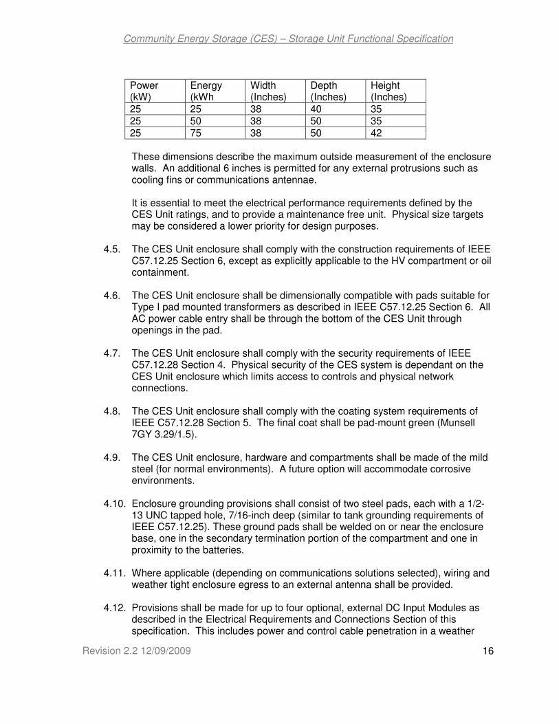
Power (kW)
Energy (kWh
Width (Inches)
Depth (Inches)
Height (Inches)
25 25 38 40 35 25 50 38 50 35 25 75 38 50 42
These dimensions describe the maximum outside measurement of the enclosure walls. An additional 6 inches is permitted for any external protrusions such as cooling fins or communications antennae. It is essential to meet the electrical performance requirements defined by the CES Unit ratings, and to provide a maintenance free unit. Physical size targets may be considered a lower priority for design purposes.
4.5. The CES Unit enclosure shall comply with the construction requirements of IEEE
C57.12.25 Section 6, except as explicitly applicable to the HV compartment or oil containment.
4.6. The CES Unit enclosure shall be dimensionally compatible with pads suitable for
Type I pad mounted transformers as described in IEEE C57.12.25 Section 6. All AC power cable entry shall be through the bottom of the CES Unit through openings in the pad.
4.7. The CES Unit enclosure shall comply with the security requirements of IEEE
C57.12.28 Section 4. Physical security of the CES system is dependant on the CES Unit enclosure which limits access to controls and physical network connections.
4.8. The CES Unit enclosure shall comply with the coating system requirements of
IEEE C57.12.28 Section 5. The final coat shall be pad-mount green (Munsell 7GY 3.29/1.5).
4.9. The CES Unit enclosure, hardware and compartments shall be made of the mild
steel (for normal environments). A future option will accommodate corrosive environments.
4.10. Enclosure grounding provisions shall consist of two steel pads, each with a 1/2-
13 UNC tapped hole, 7/16-inch deep (similar to tank grounding requirements of IEEE C57.12.25). These ground pads shall be welded on or near the enclosure base, one in the secondary termination portion of the compartment and one in proximity to the batteries.
4.11. Where applicable (depending on communications solutions selected), wiring and
weather tight enclosure egress to an external antenna shall be provided.
4.12. Provisions shall be made for up to four optional, external DC Input Modules as described in the Electrical Requirements and Connections Section of this specification. This includes power and control cable penetration in a weather

Community Energy Storage (CES) – Storage Unit Functional Specification
Revision 2.2 12/09/2009
17
tight manner. Provisions for external mounting of the DC Input Modules must not inhibit access to CES Unit modules or AC cable terminations.
4.13. A nameplate shall be provided including:
Manufacturer Name Connection diagram CES Unit ratings; Power, energy, voltage, BIL Specimen data; serial number, date of manufacture
The nameplate shall meet the requirements of IEEE C57.12.00
4.14. Signage shall indicate Source and Load side AC buses, Neutral bus, DC bus, Isolation Contactor, Module names. Custom signage will be in accordance with specific Utility requirements.
4.15. All necessary safety signs and warnings as described in ANSI Z535-2002 (entire
series from Z535.1 through Z535.6) shall be included on the CES unit box.
4.16. All necessary signs and warnings for identification of hazardous materials as described in NFPA 704 shall be included on the CES unit box.
5. Optional DC Input modules
5.1. The CES Unit shall provide for optional DC input modules which are suitable for
small wind or solar generating units. These modules will be designed to accommodate varying DC input voltage and power levels similar to the charge controllers typically provided with small wind or solar resources. These will need to be site specific requirements, permitting a small energy resource to be connected to the CES Unit DC bus. Standard options shall be supported, including Peak Power Point Voltage ranging from 50 to 400 V DC, 600 V DC Maximum open circuit voltage, and Peak Power ranging from 1 to 25 kW.
5.2. The DC Input Modules shall be instrumented with revenue meters with accuracy
to support customer billing credits. Revenue meters are required to have 2% accuracy.
5.3. The DC Input Modules may be externally mounted in separate enclosures
attached to the CES Unit Enclosure. It is not intended that the modules be added in the field, but may be supplied initially with the CES Unit as an option. It is intended that the modules be replaceable in the field. Fabrication of the CES Unit enclosure and DC bus may be customized according to the specific CES Unit order to accommodate DC Input Modules.
5.4. DC Input modules are NOT included in the dimensional constraints of the CES
Unit specified in the Enclosure section of this specification.

Community Energy Storage (CES) – Storage Unit Functional Specification
Revision 2.2 12/09/2009
18
6. Control Functions
The CES Unit Control is responsible to perform the following by priority in this order: 1. Protect itself (isolate for any internal fault) 2. Remain within power constraints (transformer and CES Unit) 3. Remain within voltage constraints 4. Isolate and perform islanding in response to system anomalies 5. Charge / discharge Real Power in response to CES Hub commands 6. Absorb / provide Reactive Power in response to CES Hub commands 7. Communicate status and diagnostic data To accomplish this, the CES Unit shall operate the Power Conversion System (PCS) and isolation contactor in response to its own control settings and local measurements and also in response to commands from the CES Control Hub. The CES Unit control will also respond to manual commands that are issued remotely or locally. “Manual” commands may be scripted into other applications within a larger DER hierarchy. Following are specific requirements of the CES Unit Control:
6.1. The control shall enact the CES Unit participation in the overall CES control scheme specified in the “Functional Specification for CES Control Hub.”
6.2. The control shall perform islanding (backup mode) as specified in the Islanding
section of this specification. 6.3. The control shall perform logging as specified in the Logging section of this
specification, including daily archiving.
6.4. The control shall participate in the time synchronization feature managed by the CES Hub and specified in the “Functional Specification for CES Control Hub.”
6.5. CES Unit operations and administration
6.5.1. The control shall respond to manual commands issued remotely or locally,
including the following:
• Change modes: Charge / discharge / standby
• Change status: Enable / disable
• Reset alarms
• Island control: Initiate / Return
• System Reset / Restart
6.5.2. A compatible CES Management Application shall be provided to permit remote or local manual monitoring and control. All settings must be viewable and settable, statuses viewable, operating parameters viewable, and logs configurable and viewable. The CES Management Application is software that

Community Energy Storage (CES) – Storage Unit Functional Specification
Revision 2.2 12/09/2009
19
may be run on a PC such as a laptop and carried into the field. Basic access levels and functions shall be:
User Type Permissions Password Functions
Viewer Read Level 1 View settings, logs Operator Read / Write Level 2 Change settings, issue
commands, download logs, view current status
Administrator Read / Write Level 3 Complete control including security, firmware updates, system configuration
6.5.3. Control buttons and indicating lights shall be provided for fundamental status
and operations without use of remote access or a locally attached PC. These shall be:
Button Light Function
Enable Enabled Enables automatic operation Disable Disabled Disables automatic operation, terminating any
Charge / discharge Reset Alarm Resets all Manual Reset Alarms Power Power On / Off, system restart Contactor Island Open / Close Isolation Contactor
The control buttons and indicating lights shall be on the exterior of the control enclosure so that they are accessible by opening the CES Unit enclosure. The physical arrangement and operation of the Isolation Contactor may make the associated button and light unnecessary.
6.6. Loss of communications or power
6.6.1. The CES Unit shall remain functional in the absence or loss of communication from the remote CES control hub. The CES Unit shall continue the previous state of charge / discharge / standby for a set time period (variable setting, 15 minute default). On expiration of the time, the CES Unit shall standby.
6.6.2. During an interruption to communications, the CES Control Hub shall make
repeated attempts to re-establish communications at a set time interval (variable setting, default of 5 minutes). When communications have been reestablished, the CES Unit and Control Hub shall make any necessary updates to resume performance as a fleet member.
6.6.3. The CES Unit control shall have non-volatile memory. In the event of total
loss of power (battery replacement or DC bus outage) the CES Unit shall retain all current and logged information and be capable of restarting without reconfiguring.

Community Energy Storage (CES) – Storage Unit Functional Specification
Revision 2.2 12/09/2009
20
6.6.4. No single mode of failure shall result in loss of power to the control and data
acquisition module.
6.6.5. Any significant loss of DC voltage shall be logged and reported by alarm. A “significant” loss of DC voltage shall be defined by a variable parameter with a default by manufacturer recommendation.
6.7. Voltage and Power Measurement and Constraints
6.7.1. The CES Unit and control shall be capable of operating in all four power quadrants in response to CES Control Hub commands or islanding requirements; real power in or out, reactive power in or out.
6.7.2. The CES Unit shall measure voltage, current, phase angle, real power and
reactive power on the source side of the Isolation Contactor and at the CES Unit AC Interface. The power flow on the load side (towards the customer) may be instrumented or may be resolved from the other two.
6.7.3. The CES Unit shall have a Report Demand Interval (variable setting; default
= 5 minutes) which is used for logging and reporting power flows.
6.7.4. The CES Unit shall have a Capacity Demand Interval (variable setting; default = 1 minute) which is used for comparing CES Unit burden and capability.
6.7.5. The CES Unit shall be voltage constrained as an override. Voltage settings
shall be variable, including associated violation time settings. If voltage at the CES Unit AC bus exceeds the Overvoltage Limit (variable setting, default = 126 V) continuously for more than the associated Overvoltage Time (variable setting; default = 15 seconds) then the CES Unit will make an adjustment. Similarly, it will respond to violation of the Undervoltage Limit for the Undervoltage Time.
When either criterion has been violated for the associated time, the CES Unit shall respond to return voltage at the CES Unit AC bus within bounds. These voltage overrides supersede any request to charge / discharge / or standby. They shall be effective only if the CES Unit is enabled; not if it is disabled or tripped.
6.7.6. The CES Unit shall have power constraints as an override. Power
constraints will be established for the CES Unit itself and for the associated transformer / secondary system. These two constraints shall be compared to the corresponding power flows based on the Capacity Demand Interval described above.

Community Energy Storage (CES) – Storage Unit Functional Specification
Revision 2.2 12/09/2009
21
If the input or output in kVA at the CES Unit AC Interface exceeds the Unit Power Limit (variable setting, default = magnitude of CES Unit Power Rating), it shall limit charge or discharge accordingly.
If the input or output in kVA at the Source bus exceeds the Secondary Power Limit (variable setting, default = Transformer Power Rating, not greater than equivalent bus rating), it shall limit charge or discharge accordingly.
If the input or output in kVA at the Load bus exceeds the Secondary Power Limit (variable setting, default = Transformer Power Rating, not greater than equivalent bus rating), it shall limit charge or discharge accordingly.
6.7.7. The CES Unit will maintain compliance with voltage and power constraints by
making adjustments with the following priority:
1.0 Adjust VAR input / output. 2.0 Adjust real power input / output
It is permissible to change charge / discharge / standby states to control voltage or power flow.
6.8. CES Control module communications
6.8.1. The CES Unit Control shall be in a separate enclosure and provide space and mounting rack for the on board communications. Space requirements and mounting rack provisions shall recognized the flexibility desired for communications as described in Section 13 (Communications). Typical control design criteria indicate the following to be adequate:
a) Maximum radio size (consider this as a box within which the radio must fit,
including mounting screws – obviously cables extend out):
Width: 7 1/2” (measured from side-to-side where the sides do not have
connectors, LED’s or other user-serviceable items).
Length: 8 3/4” (allow an additional inch for connectors)
Thickness: 2 13/16”
b) Power Supply
Nominal 12 VDC, 10.5-16 VDC
Maximum output 1A continuous, 6 A transmit, Power: Average 12 Watts, 28 Watts maximum
6.8.2. The CES Unit Control shall include a USB port, ANSI Type 2 Optical Port,
and/or Ethernet connection for administrative functions from an attached laptop PC. Physical access will be controlled by access to the CES Unit enclosure.
6.8.3. Wide area communication interfaces, for Hub, SCADA or remote
management applications, as well as any other communication interfaces such as into home networks or for local management functions shall be compliant with the emerging NIST Smart Grid cyber security requirements.

Community Energy Storage (CES) – Storage Unit Functional Specification
Revision 2.2 12/09/2009
22
7. Islanding
CES deployment is intended to perform load following at the feeder level. During normal system conditions, therefore, the discharge commands of CES will be issued by the CES Hub and the output will remain constant until an updated command is received. As shown in figure 5, residential loads, even when aggregated over several houses vary continuously and do not demonstrate the relatively smooth load profile or the consistent daily load patterns that are observed at the station. During islanding, the CES Unit will perform load following that supplies this highly variable load, including inrush to support motor starts.
Figure 5 Sample of a distribution transformer demand feeding four (4) residential loads. Source: Distribution System Modeling and Analysis, William H. Kersting (2nd Edition)

Community Energy Storage (CES) – Storage Unit Functional Specification
Revision 2.2 12/09/2009
23
7.1. Transition to Island Mode
In the event of a momentary or permanent power system outage, the CES Unit will go into islanding mode. The isolation contactor will open and the CES Unit will operate as a voltage source and perform load following to maintain service to the connected customers.
7.1.1. While system conditions are normal, in anticipation of islanding, discharge
shall be restricted to leave a minimum available energy setting, Reserve Energy (percent of rated CES Unit energy, default 20%).
7.1.2. Automated sensing and responding to anomalous system conditions shall be
in compliance with IEEE 1547-2003, specifically Section 4.2.3 on Voltage response and Section 4.2.4 on Frequency response. It is intended that the CES Unit respond to momentary or permanent outages such that electronic appliances like computers would continue to work through transition to islanding. On transition to islanding, the CES Unit shall achieve stable AC output voltage and load following within 4 cycles.
7.1.3. Islanding shall be permitted if the CES Unit is enabled regardless of the CES
Unit state; standby, discharge, or charge. 7.1.4. Islanding shall NOT occur if the CES Unit is disabled through local or remote
command, or if the CES Unit is tripped. 7.1.5. The islanding contactor will not open under conditions specified in the
Protection section of this specification. 7.1.6. Islanding may be invoked manually. The CES Unit shall respond to a remote
or local command to initiate the islanding process.
7.1.7. When the island has been established, the CES Unit will provide updated status and operating data on the next Command Interval when prompted by the CES Hub as usual. In order to avoid burden on the communications system, the update is not invoked from the CES Unit.
7.1.8. An automated transition to island shall be reported to the Outage
Management System (OMS) and considered as a customer interruption. This feature will be a customized portion of the DDC Interface specific to the Utility.
Community Energy Storage (CES) – Storage Unit Functional Specification
Revision 2.2 12/09/2009
24
7.2. Operation in Island mode
Once the island has been established, the CES Unit shall perform load following for as long as possible within the constraints described below.
7.2.1. Voltage shall be regulated to a set Island Mode Voltage level (default is 117 V). Note that this voltage setting may be intentionally low to reduce island demand, thereby extending islanding duration.
7.2.2. Power constraints remain in effect. If demand (whether natural load or fault)
exceeds CES Unit capability, the CES Unit shall trip (shut down power conversion, leave contactor open, indicate status of tripped). This condition does not inhibit automated return from an islanded condition.
7.2.3. Voltage constraints remain in effect. If the overvoltage and undervoltage
criteria cannot be met, the CES Unit shall trip (shut down power conversion, leave contactor open, indicate status of tripped).
7.2.4. Reliability data shall be logged during islanding. From the source side
voltage measurement, the duration and type (momentary or permanent) of outage will be recorded. The number of customers on the island will be logged. These data will be communicated to the CES Hub where they will be aggregated at the feeder level to calculate the impact on feeder SAIFI, SAIDI, and MAIFI.
7.2.5. At the Utility’s discretion, an Islanding Energy Allocation scheme may be
enabled through intelligent (AMI) metering. The stored energy available at the time islanding is initiated will be allocated in accordance with this scheme. In its simplest form, each customer is allocated an equal share of energy and the meter disconnect will be opened when a customer has consumed their individual allocation. This feature requires communication between the CES Unit and the associated AMI meters. The Energy Allocation scheme must properly recognize contributions by customer owned generation, whether connected to the AC or DC bus of the storage unit.
7.2.6. While in the island mode, CES shall provide a notification message back to
the CES Hub. The message shall indicate that the associated customers are on battery power and will be available for other utility applications to utilize in any form such as e-mail or text messaging. If available, an estimate of time to outage will also be determined for each customer within an energy allocation scheme.
7.2.7. Local Distributed Energy Resources (wind and/or solar) may be available to
extend islanding duration. The DC Input Modules shall remain active during islanding.
7.2.8. Islanding will consume stored energy until a set Depleted Energy setting is
reached (variable setting; percent of rated CES Unit energy, default = 1%).

Community Energy Storage (CES) – Storage Unit Functional Specification
Revision 2.2 12/09/2009
25
When the State of Charge is reduced to this level, the CES Unit shall go into standby mode, stopping all DC/AC conversion. Due to safety concerns, the isolation contactor shall remain open.
The communications and controls shall be put into a sleep mode to reduce power consumption. The CES Unit shall be capable of recovery from a Depleted Energy state for a period of not less than two weeks. One scenario of concern is a catastrophic power system outage where large numbers of CES Units may have run to a Depleted Energy state. When the normal supply is restored, the CES Units must recover in an automated fashion. Selection of the Depleted Energy setting will depend on the Manufacturer’s recommendation for depth of discharge and the reserve power desired for maintaining control power, communications, and closing energy for the isolation contactor. Accuracy of the State of Charge estimate must also be taken into consideration to assure sufficient energy to return.
Restoring the CES Unit following a Depleted Energy event will require:
• Return of system voltage, in accordance with the System Stable criteria
• Automated close of the Isolation Contactor. Timing shall be consistent with the requirements of for staged return from islanding.
• CES Unit control logging of event end and communication to dependent systems (HAN).
• Manually (remote or local) close or restore meter disconnects or Demand Response facilities that were involved as needed. This is not a CES function, but the local devices may have opened in response to CES energy allocation limits.
7.2.9. System voltage, source side of the open isolation contactor, shall be
monitored continuously during islanding in preparation to initiate the return transition.

Community Energy Storage (CES) – Storage Unit Functional Specification
Revision 2.2 12/09/2009
26
7.3. Transition from Island Mode
The Island Return process is intended to provide flexible control over the CES Fleet and optimize the participation of the affected CES Units in restoration efforts. Considerations are:
• Maintaining CES Unit charge for possible repeated outages (minimize islanding duration)
• Assuring that system conditions are stable (longer time prior to returning)
• Reducing cold load pick-up (longer time prior to returning)
• Avoiding simultaneous return of multiple CES Units (staged return times)
• Autonomous CES Unit control (minimize dependence on communications which may be burdened during outage conditions)
To accomplish this, two time intervals are required, a System Stable Interval and a Return Delay Interval.
7.3.1. Unless inhibited, the CES Unit shall automatically synchronize and perform
closed transition return following an outage. A CES Unit that tripped due to overload or fault is not inhibited.
7.3.2. The Island Return process may be inhibited by a remote or local command.
If the island is established manually, the return shall be inhibited by default, and a manual command shall be required to enable the Island Return process. The inhibit feature may be invoked manually at any time, regardless of CES Unit mode.
7.3.3. The Island Return process shall require expiration of two interval times before
closing the Islanding Contactor, the System Stable interval followed by the Return Delay interval.
7.3.4. Prior to return, the CES Unit shall measure stable system voltage (source
side of the open isolation contactor) for a set time interval (variable setting, default of 5 minutes). Stable system voltage is defined as being within specially defined voltage magnitude and frequency settings (variable settings, defaults of 115 V, 126 V, 59.3 Hz, 60.5 Hz). The voltage magnitude may be set according to expected site conditions, and the frequency may be set consistent with IEEE 1547-2003 Section 4.2.6. These settings may be selected to assure that multiple units are not returning to a system that is no able to support the returning load and that local service conditions will not be degraded by the return.
7.3.5. If the voltage and frequency criteria are not satisfied continuously during the
Stable System interval, then the Stable System interval timer shall be reset to zero and timing reinitiated when the criteria are satisfied.
7.3.6. Synchronization shall begin and the Return Delay Interval shall begin when
the Stable System interval timer has expired.

Community Energy Storage (CES) – Storage Unit Functional Specification
Revision 2.2 12/09/2009
27
7.3.7. The Return Delay interval shall be calculated at the time the Stable System interval timer expires. This is intended to spread the fleet return through a period of time (with a known maximum duration), prevent simultaneous returns, and accelerate the return of CES Units with the lower levels of charge. It may be based on the product of three values; a Return Delay Base Time setting (variable setting, default = 10 seconds), remaining charge, and a random number which is assigned automatically. The random number will be assigned within a range with a set maximum (variable setting; default = 100). For example:
Return Delay Base Time setting = 10 seconds Example CES Unit state of charge = 30% Return Delay Random Number Maximum = 100 Example CES Unit random number assignment = 70 Example CES Unit Return Delay = 10 x .3 x 70 = 210 seconds.
The requirement is to satisfy the stated objectives, not to use this suggested approach. It is intended that the staged return be highly configurable by the user.
7.3.8. Criteria for synchronization shall be in accordance with IEEE 1547 Table 5.
The Islanding Contactor shall be closed when the Return Delay interval has expired AND the synchronization criterion is satisfied.
7.3.9. The CES Unit will provide updated status and operating data on the next
Command Interval when prompted by the CES Hub as usual. In order to avoid burden on the communications system, the update is not invoked from the CES Unit.
7.4. Additional Island Mode Features
7.4.1. As a future option, a “Smart Energy Profile” compatible signal will be sent to the associated households. This signal will support local notification or enable their Demand Side Management system. The communications options for this feature include HomePlug, Zigbee, or other Home Area Network (HAN) protocols.
7.4.2. As a future option, Demand Response (DR) may be enabled through
communication to loads on a Home Area Network (HAN). When available, DR load curtailment will be used as needed to remain within power constraints and to extend islanding duration.
7.4.3. As a future option, the HAN may also be employed to manage electric vehicle
charging as a part of the CES fleet. This will require participation by the CES Hub and may be communicated through the CES Unit where appropriate.

Community Energy Storage (CES) – Storage Unit Functional Specification
Revision 2.2 12/09/2009
28
8. Logging
8.1. Time based performance data such as efficiency shall be logged, totaled and
reported (when applicable) for the following time periods:
• Command Interval (variable setting, default = 5 minutes; may vary based on system operating conditions affecting charge / discharge cycle)
• Short Analysis Interval (two variable settings: Initiate Date/time, Duration; default Initiate Date/time is next even clock hour, default Duration is 1 hour)
• Long Analysis Interval (two variable settings: Initiate Date/time, Duration; default Initiate Date/time is local midnight, default Duration is 24 hours)
• Historic Analysis (Time since Last Reset Date/time; defaults to current Date/time when the CES unit is first enabled, does not change until manually permitted to reset on next CES Unit enable)
8.2. Time based performance data logs shall be stored locally by the CES Unit for a
limited period of time. This will result in a rolling window and a fixed amount of data in storage. The defined time periods shall be as follows:
• Daily Window Log Lifetime; variable setting, default = 24 hours
• Weekly Window Lifetime; variable setting, default = 168 hours 8.3. Command Interval Log data shall be kept for the Daily Window Log Lifetime so
that these data represent a rolling 24 hour record. These data shall be available as a First In First Out record stored locally to be retrieved locally or remotely. Command Interval data are NOT reported back for system analysis and archiving.
8.4. Short Analysis Interval log data shall be kept for the Daily Window Log Lifetime
so that these data represent a rolling 24 hour record. These data shall be available as a First In First Out record stored locally to be retrieved locally or remotely. Short Analysis Interval log data shall be reported back for system analysis and archiving once per day.
8.5. Long Analysis Interval log data shall be kept for the Weekly Window Log Lifetime
so that these data represent a rolling one week record. These data shall be available as a First In First Out record stored locally to be retrieved locally or remotely. Long Analysis Interval log data shall be reported back for system analysis and archiving once per day.
8.6. Historic Analysis data are single, cumulative data points which are updated from
the Last Reset Date/time until the current time. These data shall be available as a record stored locally to be retrieved locally or remotely. Historic Analysis log data shall be reported back for system analysis and archiving once per day.

Community Energy Storage (CES) – Storage Unit Functional Specification
Revision 2.2 12/09/2009
29
8.7. A log maintenance routine shall be run on a user configurable schedule (daily). The routine shall require confirmation of successful archiving prior to deleting local logs.
8.8. The CES Unit shall calculate and log efficiencies (real energy out / real energy
in) for each of the four logging time intervals; Command Interval, Short Analysis Interval, Long Analysis Interval, and Historic.
8.9. The CES Unit shall calculate and log the real and reactive energy flow for each of
the four logging time intervals; Command Interval, Short Analysis Interval, Long Analysis Interval, and Historic.
8.10. The CES Unit shall perform special computations and logging for reliability
analysis as described in the section on Islanding.
8.11. Requirements for logging of alarms and fundamental operating and performance data are described in another section of this specification.
9. Environmental
CES shall be designed to perform all its functions in the following outdoor environment:
Operating Ambient Temperature: -30°C to +50°C
Survival Ambient Temperature: -40°C to +60°C Humidity: 10% to 100% condensing
Transportation / Storage Ambient Temp: -30°C to +50°C for up to 6 months Altitude: Sea level to 2000 m without kVA
derating Seismic risk: Uniform Building Code Zone 4
10. Harmonics, Noise and EMI emissions
10.1. It is not intended initially to utilize the CES Unit to correct harmonics. This
requirement presumes the system is connected to a clean system and limits the contribution to distortion. Following are the requirements on current and voltage harmonics of CES at the point of common coupling to the utility system:
• Total Demand Distortion (TDD) at 50%-100% of rated power < 5%
• Individual harmonic currents during peak shaving (as a source) per IEEE Std. 1547-2003
• Individual harmonic currents during charging & standby (as a load) per IEEE Std. 519-1992
10.2. CES noise level shall not exceed 48 dBA at 10 meters away from the system.
This is based on the average neighborhood noise at night time.

Community Energy Storage (CES) – Storage Unit Functional Specification
Revision 2.2 12/09/2009
30
10.3. CES EMI shall not exceed levels established in the FCC Code of Federal
Regulations in Sections 15.109 and 15.209. In addition, CES shall have the capability to withstand EMI in accordance with IEEE Std. C37.90.2-1995.
11. Computer Models
The CES Unit supplier shall provide information suitable for development of models for the digital simulation of the CES Unit response to all operating modes and to anomalous conditions. Supplier engineers shall work with the owner in developing simulation models and shall promptly communicate changes to the models as the design evolves. The intent of this requirement is to provide adequate information regarding operational characteristics so that associated studies can be undertaken. For example, if the CES Unit is connected with a known source side driving point impedance and a motor of known starting characteristics is started, it is desired to know how the CES Unit will respond and what impact it will have on voltages and currents.
Community Energy Storage (CES) – Storage Unit Functional Specification
Revision 2.2 12/09/2009
31
12. Protection
12.1. The CES Unit shall be self protecting for AC or DC component failures.
Protection shall coordinate with pad-mount transformer internal fusing such that the CES Unit is isolated while the isolating contactor remains closed and the load remains on the grid. If adequate fault interrupting capability is not provided, then the transformer protection or grid protection may be used for handling catastrophic failures.
12.2. The CES Unit shall use directional current sensing to distinguish between source
and load side faults so that it will not attempt to open the islanding contactor for load side faults.
12.3. The CES Unit shall use over current sensing to inhibit opening of the islanding
contactor for any condition that exceeds the interrupting capability of the contactor.
12.4. The CES Unit shall stand by (isolate itself and associated load from the grid by
opening the isolating contactor and not discharge) when:
• An uncorrectable voltage violation occurs
• Loss of neutral is detected by neutral shift relative to ground
• Current exceeds the storage maximum momentary capacity (fault in island mode)
12.5. The CES Unit shall initiate islanding (isolate itself and associated load from the
grid by opening the isolating contactor and discharge to follow load) when loss of grid power is detected.
12.6. Response to grid faults are expected to be as described for the zones below:
1. a) Source to CES tap (CES Unit phase involved) – Source side sectionalizing
device operates, CES Unit transitions to island (OMS notified). b) Source to CES tap (CES Unit phase NOT involved) – Source side sectionalizing device operates, CES Unit may / may not transition to island, depending on voltage transient.
2. Down-line from CES tap, away from CES Unit - CES Unit may / may not transition to island, depending on voltage transient.
3. CES tap, ahead of transformer fuse - Source side sectionalizing device operates, CES Unit transitions to island (OMS notified).
4. Transformer fuse to CES Unit source side current sensor – transformer fuse operates, CES Unit transitions to island (OMS notified).
5. Load side of CES Unit source side current sensor, load side of CES Unit internal current sensor, source side of customers’ breakers:
a. CES Unit load side fault is detected because current magnitude is above a variable setting (CES Control setting) and current direction is towards load.

Community Energy Storage (CES) – Storage Unit Functional Specification
Revision 2.2 12/09/2009
32
b. Opening of the isolation contactor is inhibited and the CES Unit goes into standby mode.
c. Transformer fuse operates. d. Current magnitude remains below the isolation contactor interrupting
capability (CES control setting) and voltage remains low (zero) for a set time (variable setting; default = 5 sec), isolation contactor opens.
e. System disabled, power out message sent to OMS.
6. Load side of CES Unit source side current sensor, load side of CES Unit internal current sensor, load side of customer breaker:
a. CES Unit load side fault is detected because current magnitude is above a variable setting (CES Control setting) and current direction is towards load.
b. Opening of the isolation contactor is inhibited and the CES Unit goes into standby mode.
c. Customer breaker opens. d. Current magnitude remains below the isolation contactor interrupting
capability (CES control setting) and voltage remains stable (within voltage constraints) for a set time (variable setting; default = 5 sec), CES Unit returns to normal operation; charge / discharge / standby.
e. Message sent to OMS – secondary fault detected, system normal. ~
Z6 Z5 Z4
B LOAD
CES
Breaker
Station Transformer
Z1
Z2
Z3
CES tap line
Branch Line
Line Transformer
CT
Customer Breaker

Community Energy Storage (CES) – Storage Unit Functional Specification
Revision 2.2 12/09/2009
33
13. Communications
The CES Unit shall include multiple communications options such as cellular, mesh node, Wi-Fi, and Wi-Max. Selection between communications options will depend on specific sites. An appropriate communications board and antenna shall be provided when this determination is made. The preferred control interface protocol is DNP3. IEC-61850 is an acceptable alternative between the Hub and the CES Unit. The control interface protocol will be specified by the purchaser.

Community Energy Storage (CES) – Storage Unit Functional Specification
Revision 2.2 12/09/2009
34
14. Factory Acceptance Testing
The system supplier shall conduct system operation tests according to applicable standards and procedures included in IEEE Standard 1547.1-2005, and agreed upon between the purchaser and the system supplier. Representatives from the purchaser and the supplier shall be allowed to participate in factory acceptance tests covering the functionality of all system components at partial rated power. The acceptance test plan shall be designed to provide confirmation of the CES Unit ratings based on an agreed reference duty cycle.

Community Energy Storage (CES) – Storage Unit Functional Specification
Revision 2.2 12/09/2009
35
15. CES Unit Alarms and Status
The CES Units will provide status and alarm information to the DDC. The interface may be via the CES Hub or an intermediate platform. Aggregate CES fleet data will be provided by the CES Hub. Date/time stamps are required in all logs. Time synchronization will be managed by the CES Hub. The CES Unit control shall provide a feature to synchronize in response to the (GPS based) CES Hub time management feature.
15.1. Individual CES Unit Alarms are tabulated here. All alarms shall be time stamped.
Alarm Action Reset
Overvoltage Trip Manual
Undervoltage Warning Manual
Battery Temp Inhibit Auto
Reserve Energy Inhibit Auto
Minimum Energy Trip Manual
PCS Temp Trip Manual
Unit Capacity Trip Manual
Trans Capacity Trip Manual
DC Bus Voltage Warning Auto
Unit Shutdown Trip Manual
Comm Failure Warning Auto
15.2. CES Unit status to the aggregator (CES Hub) for interface and ultimate DDC display will be provided in the form of operating parameters tabulated here.
Mode Standby/Tripped/Available
Unit Real Power In / Out kW
Unit Reactive Power In / Out kVAR
AC Voltage 240/120 Volts
Trans Power In / Out kVA
Island Duration Min
State of Charge Percent

Community Energy Storage (CES) – Storage Unit Functional Specification
Revision 2.2 12/09/2009
36
16. CES Unit Settings and Operating Parameters
16.1. Following are CES Unit settings. All settings shall be accessible remotely or locally through a connected PC.
Setting Instance Measurement Units Default
Charge Level timeout
on loss of communications Time minutes 15
Discharge Level timeout
on loss of communications Time minutes 15
Communications retry
on loss of communications Time minutes 5
Command Interval From hub Time minutes 5
Short Analysis Interval Schedule Log / analysis Date/Time Date/Time start
Short Analysis Interval Duration Log / analysis Time minutes 60
Long Analysis Interval Schedule Log / analysis Date/Time Date/Time start
Long Analysis Interval Duration Log / analysis Time hours 24
Daily Log Life Log maintenance Time hours 24
Weekly Log Life Log maintenance Time hours 168
Performance Exclusions Data bounds
Multiple definitions
As needed multiple
Overcurrent pickup In service current Amps
Overvoltage Limit In service voltage Volts 126
Overvoltage Time In service Time seconds 15
Undervoltage Limit In service voltage Volts 114
Undervoltage Time In service Time seconds 15
Rated power Fixed power KVA
Rated energy Fixed energy kWh
Power Limit Fixed power kVA Rating
Secondary P Limit Fixed power kVA
Tran rating

Community Energy Storage (CES) – Storage Unit Functional Specification
Revision 2.2 12/09/2009
37
Setting Instance Measurement Units Default
Transformer rating Fixed power KVA
Tran Impedance Fixed Impedance percent 1.5
Tran X/R Fixed X/R ratio 1
Reserve energy In service energy
percent of rated 20
Depleted energy In service energy
percent of rated
1
V regulated Islanded voltage Volts 117
System Stable Delay Islanded time minutes 5
Return Delay Base Islanded time seconds 10 Return Number Range Islanded integer Max 100
System V min Islanded voltage Volts 115
System V max Islanded voltage Volts 126
System Freq Min Islanded frequency Hz 59.3
System Freq Max Islanded frequency Hz 60.5
Synch Angle Islanded V angle degrees 5
CES Unit Settings and Operating Parameters (continued table)

Community Energy Storage (CES) – Storage Unit Functional Specification
Revision 2.2 12/09/2009
38
16.2. Following are CES Unit inputs from the CES Hub for dispatch of power;
charge or discharge. This excludes updates and commands which are also communicated at intervals.
FROM HUB
16.3. Following are CES Unit outputs to the CES Hub for dispatch of power; charge or discharge. This excludes status, logs, and alarms which are also communicated at intervals.
TO HUB
Reactive Power Request In / Out Percent
Real Power Request In / Out Percent
Real Power Actual In / Out kW
Reactive Power Actual In / Out kVAR
Available Energy SOC - reserve kWh
Voltage Each Leg at PCS V

Community Energy Storage (CES) – Storage Unit Functional Specification
Revision 2.2 12/09/2009
39
17. Standards & Code Compliance
The CES and subsystems shall be designed, manufactured, and tested according to the latest revision of applicable standards including but not limited to IEEE, ANSI, NEC, and NEMA. Equipment furnished shall meet the guidelines defined in the applicable portions of standards listed in the Table below. APPLICABLE STANDARDS & CODES
1 ANSI/IEEE Std C2-2007TM
National Electrical Safety Code.
2 ANSI C57.12.25-1990
Pad-Mounted Transformer Requirements
3 ANSI C57.12.28-2005
Pad-Mounted Equipment Enclosure Integrity
4 ANSI Z535 – 2002
Product Safety Signs and Labels.
5 FCC Sections15.109 & 15.209
FCC Code of Federal Regulations Radiated Emission Limits; General Requirements.
6 IEEE Std 519-1992TM IEEE Recommended Practices and Requirements for Harmonic Control in Electrical Power Systems.
7 IEEE Standard 1547-2003 (R 2008)TM
IEEE Standard for Interconnecting Distributed Resources with Electric Power Systems.
8 IEEE Standard 1547.1-2005 TM
IEEE Standard Conformance Test Procedures for Equipment Interconnecting Distributed Resources with Electric Power Systems
9 IEEE Standard 1547.2-2008 TM
Interconnecting Distributed Resources with Electric Power Systems
10 IEEE Standard 1547.3-2007 TM
Guide for Monitoring, Information Exchange, and Control of Distributed Resources Interconnected with Electric Power Systems
11 IEEE C37.90.2-2004 TM
IEEE Standard Withstand Capability of Relay Systems to Radiated Electromagnetic Interference from Transceivers.
12 IEEE Std. C37.90.1-2002 TM
IEEE Standard for Surge Withstand Capability (SWC) Tests for Protective Relays and Relay Systems (ANSI).
13 IEEE Std. C62.41-1991(R 1995) TM
IEEE Recommended Practice on Surge Voltages in Low-Voltage AC Power Circuits.
14 IEEE Std. C62.41.1-2002 TM
IEEE Guide on the Surges Environment in Low-Voltage (1000V and Less) AC Power Circuits.
15 IEEE Std. C62.41.2-2002 TM
IEEE Recommended Practice on Characterization of Surges in Low-Voltage (1000 V and Less) AC Power Circuits.
16 IEEE Standard C62.45-2002 TM
IEEE Recommended Practice on Characterization of Surges in Low-Voltage (1000 V and Less) AC Power Circuits.
17 NFPA 704 Standard System for the Identification of the Hazards of Materials for Emergency Response.
18 Smart Energy Profile (SEP)
Standard system for communication with demand side management equipment

Community Energy Storage (CES) – Storage Unit Functional Specification
Revision 2.2 12/09/2009
40
19 Uniform Building Code
Applicable to seismic rating (i.e., up to 5% peak acceleration with 10% probability of being exceeded in 50 years)
20 UL 1778 Underwriters Laboratory’s Standard for UNINTERRUPTIBLE POWER SYSTEMS (UPS) for up to 600V A.C.
21 UL 1741 UL Standard for Inverters, Converters, Controllers and Interconnection System Equipment for Use With Distributed Energy Resources

Community Energy Storage (CES) – Storage Unit Functional Specification
Revision 2.2 12/09/2009
41
APPENDIX A – CES UNIT FUNCTIONAL SPECIFICATION LICENSE
Community Energy Storage Unit
Functional Specification License
This Community Energy Storage Unit Functional Specification (“specification”) is a collaborative effort of AMERICAN ELECTRIC POWER COMPANY and Others (as indicated in the specification acknowledgements), and is protected by copyright and/or other applicable law. Any use of the specification other than as authorized under this license or copyright law is prohibited.
By exercising any rights to the specification provided herein, you accept and agree to be bound by the terms of this license. To the extent this license may be considered to be a contract, the licensor grants you the rights contained here in consideration of your acceptance of such terms and conditions. 1.0 Definitions: 1.1 “Collective Work” means a work, such as a periodical issue, anthology or encyclopedia, in which the Specification in its entirety in unmodified form, along with one or more other contributions, constituting separate and independent works in themselves, are assembled into a collective whole. A work that constitutes a Collective Work will not be considered a Derivative Work (as defined below) for the purposes of this License. 1.2 “Derivative Work” means a work based upon the Specification or upon the Specification and other pre-existing works; including, but not limited to, a translation, abridgment, condensation, or any other form in which the Specification may be recast, transformed, or adapted, except that a work that constitutes a Collective Work will not be considered a Derivative Work for the purpose of this License. 1.3 “Licensors” means American Electric Power Company and Others, as listed in the Acknowledgements. 1.4 “Specification” has the meaning as set forth in the opening paragraph of this License. 1.5 “You” means an individual or entity exercising rights under this License who has not previously violated the terms of this License with respect to the Specification. 2.0 License Grant: Subject to the terms and conditions of this License, Licensors hereby grants You a worldwide, royalty-free, non-exclusive, perpetual (for the duration of the applicable copyright) license to exercise the rights in the Specification as stated below. The rights granted below may be exercised in all media and formats whether now known or hereafter devised, and include the right to make such modifications as are technically necessary to exercise the rights in other media and formats. All rights not expressly granted by Licensors are hereby reserved.

Community Energy Storage (CES) – Storage Unit Functional Specification
Revision 2.2 12/09/2009
42
2.1 You may incorporate the Specification into one or more Collective Works and may reproduce the Specification as incorporated in the Collective Works. 2.2 You may create and reproduce Derivative Works provided that any such Derivative Work, including any translation in any medium, takes reasonable steps to clearly label, demarcate or otherwise identify that changes were made to the original Specification. For example, a modification shall indicate, "The Specification has been modified." 2.3 You may make copies of the Specification and you may distribute copies of the Specification by print or digital means, including as incorporated in Collective Works. 3.0 Restrictions. The license granted in Section 2.0 above is expressly made subject to and limited by the following restrictions: 3.1 You may distribute the Specification only under the terms of this License, and (a) You must include a copy of this License with every copy of the Specification You distribute; (b) You may not offer or impose any terms on the Specification that restrict the terms of this License or the ability of a recipient of the Specification to exercise of the rights granted to that recipient under the terms of this License; (c) You may not sublicense the Specification; (d) You must keep intact all notices that refer to this License and to the disclaimer of warranties; and (e) if You distribute the Specification, You may not impose any technological measures on the Specification that restrict the ability of a recipient of the Specification from You to exercise of the rights granted to that recipient under the terms of the License. 3.2. You may distribute a Derivative Work only under the terms of this License, and (a) You must include a copy of this License with every copy of each Derivative Work You distribute; (b) You may not offer or impose any terms on the Derivative Works that restrict the terms of this License or the ability of a recipient of the Specification to exercise the rights granted to that recipient under the terms of this License; (c) You must keep intact all notices that refer to the License and to the disclaimer of warranties; and (d) if You distribute the Specification, You may not impose any technological measures on the Derivative Work that restrict the ability of a recipient of the Derivative Work from You from exercising the rights granted to that recipient under the terms of this License. 3.3 If You distribute the Specification or any Derivative Works or any Collective Works, You must, unless requested otherwise in writing by Licensors, keep intact all copyright notices for the Specification, include a credit identifying the Licensors as the original authors of the Specification, and in the case of a Derivative Work, include a credit identifying the use of the Specification and the Licensors as the original authors of the Specification in the Derivative Work. For the avoidance of doubt, You may only use the credit required by this Section for the purpose of attribution in the manner set out above and, by exercising Your rights under this License, You may not implicitly or explicitly assert or imply any connection with, sponsorship or endorsement by the Licensors of You or Your use of the Specification, without the separate, express prior written permission of each of the Licensors. 4. Representations, Warranties and Disclaimer. Unless otherwise mutually agreed to by the parties in writing, licensors offers the specification as-is and only to the extent of any rights held in the licensed specification by the licensors. The licensors makes no

Community Energy Storage (CES) – Storage Unit Functional Specification
Revision 2.2 12/09/2009
43
representations or warranties of any kind concerning the specification, express, implied, statutory or otherwise, including, without limitation, warranties of title, marketability, merchantability, fitness for a particular purpose, noninfringement, or the absence of latent or other defects, accuracy, or the presence of absence of errors, whether or not discoverable. Some jurisdictions do not allow the exclusion of implied warranties, so such exclusion may not apply to you.
5. Limitation of Liability. Except to the extent required by applicable law, in no event will licensors be liable to you on any legal theory for any special, incidental, consequential, punitive or exemplary damages arising out of this license or the use of the specification, even if licensors have been advised of the possibility of such damages.
6. Termination 6.1 This License and the rights granted hereunder will terminate automatically upon any breach by You of the terms of this License. Individuals or entities who have received Derivative Works or Collective Works from You under this License, however, will not have their licenses terminated provided such individuals or entities remain in full compliance with those licenses. Sections 1, 4, 5, 6, 7, and 7 will survive any termination of this License. 6.2 Subject to the above terms and conditions, the license granted here is perpetual (for the duration of the applicable copyright in the Specification). Notwithstanding the above, Licensors reserves the right to release the Specification under different license terms or to stop distributing the Specification at any time; provided, however that any such election will not serve to withdraw this License (or any other license that has been, or is required to be, granted under the terms of this License), and this License will continue in full force and effect unless terminated as stated above. 7. Miscellaneous 7.1 Each time You distribute or publicly digitally perform the Specification or a Collective Work, the Licensors offers to the recipient a license to the Specification on the same terms and conditions as the license granted to You under this License.
7.2 Each time You distribute a Derivative Work, Licensors offers to the recipient a license to the original Specification on the same terms and conditions as the license granted to You under this License.
7.3 If any provision of this License is invalid or unenforceable under applicable law, it shall not affect the validity or enforceability of the remainder of the terms of this License, and without further action by the parties to this agreement, such provision shall be reformed to the minimum extent necessary to make such provision valid and enforceable.
7.4 No term or provision of this License shall be deemed waived and no breach consented to unless such waiver or consent shall be in writing and signed by the party to be charged with such waiver or consent.
7.5 This License shall be governed by the laws of the State of Ohio without regard to its conflict of laws provisions.

Community Energy Storage (CES) – Storage Unit Functional Specification
Revision 2.2 12/09/2009
44
7.6 This License constitutes the entire agreement between the parties with respect to the Specification licensed here. There are no understandings, agreements or representations with respect to the Specification not specified here. Licensors shall not be bound by any additional provisions that may appear in any communication from You. This License may not be modified without the mutual written agreement of the Licensors and You.