functionality test for ethernet based access nodes · functionality tests for ethernet based access...
TRANSCRIPT

TECHNICAL REPORT
© The Broadband Forum. All rights reserved.
TR-254
Functionality Tests for Ethernet Based Access Nodes
Issue: 1
Issue Date: July 2012

Functionality Tests for Ethernet Based Access Nodes TR-254 Issue 1
July 2012 © The Broadband Forum. All rights reserved 2 of 58
Notice
The Broadband Forum is a non-profit corporation organized to create guidelines for broadband
network system development and deployment. This Broadband Forum Technical Report has
been approved by members of the Forum. This Broadband Forum Technical Report is not
binding on the Broadband Forum, any of its members, or any developer or service provider. This
Broadband Forum Technical Report is subject to change, but only with approval of members of
the Forum. This Technical Report is copyrighted by the Broadband Forum, and all rights are
reserved. Portions of this Technical Report may be copyrighted by Broadband Forum members.
This Broadband Forum Technical Report is provided AS IS, WITH ALL FAULTS. ANY
PERSON HOLDING A COPYRIGHT IN THIS BROADBAND FORUM TECHNICAL
REPORT, OR ANY PORTION THEREOF, DISCLAIMS TO THE FULLEST EXTENT
PERMITTED BY LAW ANY REPRESENTATION OR WARRANTY, EXPRESS OR
IMPLIED, INCLUDING, BUT NOT LIMITED TO, ANY WARRANTY:
(A) OF ACCURACY, COMPLETENESS, MERCHANTABILITY, FITNESS FOR A
PARTICULAR PURPOSE, NON-INFRINGEMENT, OR TITLE;
(B) THAT THE CONTENTS OF THIS BROADBAND FORUM TECHNICAL REPORT ARE
SUITABLE FOR ANY PURPOSE, EVEN IF THAT PURPOSE IS KNOWN TO THE
COPYRIGHT HOLDER;
(C) THAT THE IMPLEMENTATION OF THE CONTENTS OF THE TECHNICAL REPORT
WILL NOT INFRINGE ANY THIRD PARTY PATENTS, COPYRIGHTS,
TRADEMARKS OR OTHER RIGHTS.
By using this Broadband Forum Technical Report, users acknowledge that implementation may
require licenses to patents. The Broadband Forum encourages but does not require its members
to identify such patents. For a list of declarations made by Broadband Forum member
companies, please see http://www.broadband-forum.org. No assurance is given that licenses to
patents necessary to implement this Technical Report will be available for license at all or on
reasonable and non-discriminatory terms.
ANY PERSON HOLDING A COPYRIGHT IN THIS BROADBAND FORUM TECHNICAL
REPORT, OR ANY PORTION THEREOF, DISCLAIMS TO THE FULLEST EXTENT
PERMITTED BY LAW (A) ANY LIABILITY (INCLUDING DIRECT, INDIRECT, SPECIAL,
OR CONSEQUENTIAL DAMAGES UNDER ANY LEGAL THEORY) ARISING FROM OR
RELATED TO THE USE OF OR RELIANCE UPON THIS TECHNICAL REPORT; AND (B)
ANY OBLIGATION TO UPDATE OR CORRECT THIS TECHNICAL REPORT.
Broadband Forum Technical Reports may be copied, downloaded, stored on a server or
otherwise re-distributed in their entirety only, and may not be modified without the advance
written permission of the Broadband Forum.
The text of this notice must be included in all copies of this Broadband Forum Technical Report.

Functionality Tests for Ethernet Based Access Nodes TR-254 Issue 1
July 2012 © The Broadband Forum. All rights reserved 3 of 58
Issue History
Issue
Number
Approval
Date
Publication
Date
Issue
Editors
Changes
1 2 July 2012 9 July 2012 Piotr Pisarczyk,
Telekomunikacja Polska
Original
Comments or questions about this Broadband Forum Technical Report should be directed to
Editor Piotr Pisarczyk Telekomunikacja Polska
End to End Architecture
WG Chairs:
David Allan
David Thorne
Ericsson
BT
Vice Chair: Sven Ooghe Alcatel-Lucent
Chief Editor Michael Hanrahan Huawei Technologies

Functionality Tests for Ethernet Based Access Nodes TR-254 Issue 1
July 2012 © The Broadband Forum. All rights reserved 4 of 58
TABLE OF CONTENTS
EXECUTIVE SUMMARY .......................................................................................................6
1 PURPOSE AND SCOPE ...................................................................................................7
1.1 PURPOSE ......................................................................................................................7
1.2 SCOPE ..........................................................................................................................7
2 REFERENCES AND TERMINOLOGY..........................................................................8
2.1 CONVENTIONS ..............................................................................................................8 2.2 REFERENCES ................................................................................................................8
2.3 ABBREVIATIONS ...........................................................................................................9
3 TECHNICAL REPORT IMPACT ................................................................................. 10
3.1 ENERGY EFFICIENCY .................................................................................................. 10 3.2 IPV6........................................................................................................................... 10 3.3 SECURITY ................................................................................................................... 10
3.4 PRIVACY .................................................................................................................... 10
4 TEST METHODOLOGY ............................................................................................... 11
4.1 TEST SETUP ............................................................................................................... 11 4.1.1 Access Node ...................................................................................................... 11
4.1.2 CPE ................................................................................................................... 12 4.1.3 Traffic generator/analyzer .................................................................................. 12
5 TEST CASES COVERING REQUIREMENTS FROM TR-101 ISSUE 2 ................... 13
5.1 QOS ........................................................................................................................... 13 5.2 L2 SECURITY CONSIDERATIONS .................................................................................. 14
5.2.1 Broadcast Handling ............................................................................................ 14 5.2.2 MAC Address Flooding ..................................................................................... 16
5.3 ADDITIONAL IWF FOR IPOE BASED ACCESS IN N:1 VLANS ........................................ 17 5.3.1 DHCP Processing............................................................................................... 17
5.3.2 ARP Processing and IP Spoofing Prevention ...................................................... 21 5.4 ACCESS LOOP IDENTIFICATION AND CHARACTERIZATION ............................................ 23
5.4.1 DHCP Relay Agent ............................................................................................ 23 5.4.2 PPPoE Intermediate Agent ................................................................................. 25
5.4.3 Access Loop Identification Configuration and Syntax ........................................ 27 5.4.4 Access Loop Characteristics ............................................................................... 32
5.5 BASELINE MULTICAST DESCRIPTION ........................................................................... 36
5.5.1 Per User-facing Port and VLAN Requirements .................................................. 36 5.5.2 Access Node Configuration Requirements ......................................................... 40
6 TEST CASES COVERING REQUIREMENTS FROM TR-177 .................................. 45
6.1 VLANS ...................................................................................................................... 45
6.2 QOS TRAFFIC CLASSIFICATION AND CLASS OF SERVICE BASED FORWARDING ............. 45 6.3 IPV6 INTERWORKING FUNCTIONS................................................................................ 46
6.3.1 DHCPv6 Processing ........................................................................................... 46

Functionality Tests for Ethernet Based Access Nodes TR-254 Issue 1
July 2012 © The Broadband Forum. All rights reserved 5 of 58
6.3.2 Neighbor Discovery Processing ......................................................................... 50 6.3.3 IPv6 Spoofing Prevention .................................................................................. 54
6.3.4 Impact of IPv4 address exhaustion on IPv4 multicast ......................................... 57
List of Figures
Figure 1 – Scenario of Functionality Tests for Ethernet Based Access Nodes ............................ 11
List of Tables
Table 1. QoS configuration ....................................................................................................... 13
Table 2. Frames rate limitation .................................................................................................. 14 Table 3. Values of possible learned MAC addresses or MAC flooding protection disabled ........ 16 Table 4. Test cases for option-82 ............................................................................................... 18
Table 5. Values of maximum number of simultaneous multicast groups .................................... 43 Table 6. Ethertype filters ........................................................................................................... 45
Table 7. P-bit marking ............................................................................................................... 46

Functionality Tests for Ethernet Based Access Nodes TR-254 Issue 1
July 2012 © The Broadband Forum. All rights reserved 6 of 58
Executive Summary
TR-254 provides a test plan that may be used to verify the functionality of Ethernet based Access
Nodes. It is based on requirements defined in the following Broadband Forum Technical
Reports:
- TR-101 Issue 2, Migration to Ethernet-Based Broadband Aggregation
- TR-177, IPv6 in the context of TR-101
A subset of requirements from these Technical Reports has been chosen for inclusion in this test
plan. Each of the test cases is designed to verify a specific requirement or set of related
requirements.
Functionality Tests for Ethernet Based Access Nodes TR-254 Issue 1
July 2012 © The Broadband Forum. All rights reserved 7 of 58
1 Purpose and Scope
1.1 Purpose
Network operators who want to follow the architecture and requirements defined by the
Broadband Forum need to know whether the equipment they are intending to deploy provides the
specified functionality that they require. Vendors also use various tests when developing their
network equipment. Vendors and network operators currently perform their own validation
(qualification) testing, but so far there has been no common, published test plan.
A common test plan can give several advantages:
easier management of the validation process owing to having common, well known
requirements and test methodology
simple way of comparing of the quality of tested equipment
cost savings:
o smaller number of problems detected during the qualification phase done by network
operators as problems should have been identified and fixed by prior vendor testing
o it offers opportunity to automate validation of new software releases
TR-254 describes a series of tests for Access Nodes that are intended for use by both Operators
and Vendors.
1.2 Scope
This Technical Report defines includes a limited set of key test cases that can verify the
functionality of Access Nodes. The tests cases are intended to be used by network operators,
vendors and test laboratories to check if devices meet a subset of the requirements presented in
the following Broadband Forum documents:
- TR-101 Issue 2, Migration to Ethernet-Based Broadband Aggregation
- TR-177, IPv6 in the context of TR-101
As these Technical Reports contain a very large number of requirements, it would be impractical
to completely test them all. A subset has therefore been chosen to verify the particular functions
of Access Nodes implementations that have been found to be the most critical to real-world
service providers’ deployments.
Test cases for other network elements (RG, Aggregation Nodes, BNG) are out of scope of this
Technical Report, but may be the subject of future Technical Reports.

Functionality Tests for Ethernet Based Access Nodes TR-254 Issue 1
July 2012 © The Broadband Forum. All rights reserved 8 of 58
2 References and Terminology
2.1 Conventions
In this Technical Report, several words are used to signify the requirements of the specification.
These words are always capitalized. More information can be found be in RFC 2119 [3].
MUST This word, or the term “REQUIRED”, means that the definition is an
absolute requirement of the specification.
MUST NOT This phrase means that the definition is an absolute prohibition of the
specification.
SHOULD This word, or the term “RECOMMENDED”, means that there could
exist valid reasons in particular circumstances to ignore this item, but
the full implications need to be understood and carefully weighed
before choosing a different course.
SHOULD NOT This phrase, or the phrase "NOT RECOMMENDED" means that there
could exist valid reasons in particular circumstances when the
particular behavior is acceptable or even useful, but the full
implications need to be understood and the case carefully weighed
before implementing any behavior described with this label.
MAY This word, or the term “OPTIONAL”, means that this item is one of
an allowed set of alternatives. An implementation that does not
include this option MUST be prepared to inter-operate with another
implementation that does include the option.
2.2 References
The following references are of relevance to this Technical Report. At the time of publication,
the editions indicated were valid. All references are subject to revision; users of this Technical
Report are therefore encouraged to investigate the possibility of applying the most recent edition
of the references listed below.
A list of currently valid Broadband Forum Technical Reports is published at www.broadband-
forum.org.
Document Title Source Year
[1] TR-101
Issue 2
Migration to Ethernet-Based Broadband Aggregation BBF 2011
[2] TR-177 IPv6 in the context of TR-101 BBF 2011
[3] RFC 2119 Key words for use in RFCs to Indicate Requirement
Levels
IETF 1997

Functionality Tests for Ethernet Based Access Nodes TR-254 Issue 1
July 2012 © The Broadband Forum. All rights reserved 9 of 58
2.3 Abbreviations
This Technical Report uses the following abbreviations:
AN Access Node
BNG Broadband Network Gateway
CoS Class of Service
CPE Customer Premises Equipment
DHCP Dynamic host configuration protocol version 4
DHCPv6 Dynamic host configuration protocol version 6
ETH Ethernet
IGMP Internet Group Management Protocol
IP Internet Protocol version 4
IPv6 Internet Protocol version 6
LDRA Lightweight DHCPv6 Relay
MDF Main Distribution Frame
PADI PPPoE active discovery initiation
PADR PPPoE active discovery request
PADS PPPoE active discovery session confirmation
PADT PPPoE active discovery terminate
PPPoE PPP over Ethernet
QoS Quality of Service
RA Router Advertisement
RG Residential Gateway
RS Router Solicitation
VID VLAN ID
VLAN Virtual LAN

Functionality Tests for Ethernet Based Access Nodes TR-254 Issue 1
July 2012 © The Broadband Forum. All rights reserved 10 of 58
3 Technical Report Impact
3.1 Energy Efficiency
TR-254 has no impact on Energy Efficiency.
3.2 IPv6
TR-254 has no impact on IPv6.
3.3 Security
TR-254 has no impact on Security.
3.4 Privacy
TR-254 has no impact on Privacy

Functionality Tests for Ethernet Based Access Nodes TR-254 Issue 1
July 2012 © The Broadband Forum. All rights reserved 11 of 58
4 Test Methodology
4.1 Test setup
Figure 1 shows the basic test setup for all the test cases presented in TR-254.
Access loop
Ethernet traffic
generator/analyzer
CPE_2
Eth_1
Eth_0
V interfaceU interface
Access
Node
M
D
F
CPE_1
Eth_2
Figure 1 – Scenario of Functionality Tests for Ethernet Based Access Nodes
4.1.1 Access Node
The Access Node is the device under test and is connected directly to the Eth_0 port of the traffic
generator/analyzer on one side and to the CPE on another side. As mentioned in TR-101 Issue 2
[1]:
“The physical layer of the U interface considered by this document includes, but is not limited to
the following technologies:
ADSL1 – ITU-T G.992.1
ADSL2 - ITU-T G.992.3
ADSL2plus - ITU-T G.992.5
VDSL2 - ITU-T G.993.2
G.SHDSL – ITU-T G.991.2
Any point-to-point 802.3 Ethernet Physical layer
Bonding of multiple DSL pairs – ITU-T G.Bond (ATM transport (G.998.1), and
Ethernet transport (G.998.2)) “
All test cases were written without specifying the physical layer, and so can be used for any kind
of access.
During all tests the Access Node must be stable. If reset or reboot of the node should occur, the
whole testing process can be considered failed. This include: reboot of shelf, board or physical
layer instability.

Functionality Tests for Ethernet Based Access Nodes TR-254 Issue 1
July 2012 © The Broadband Forum. All rights reserved 12 of 58
4.1.2 CPE
The number of items of CPE needed in each test (if different from the basic setup) is specified in
the test setup.
R-1 All CPEs MUST be configured in bridge mode to ensure that specific functions (PPPoE,
DHCP, IPv6) are implemented on the Ethernet ports of traffic generator/analyzer and not
on the CPE.
4.1.3 Traffic generator/analyzer
One side of the traffic generator/analyzer represents the user equipment (Eth_1, Eth_2) and the
other side represents the core equipment (Eth_0).
R-2 On both sides the traffic generator/analyzer MUST be able to perform specific functions
such as:
DHCPv4/v6 server and client,
Neighbor Discovery IPv6,
PPPoE server and client,
IGMP host and querier.
R-3 The Traffic generator/analyzer MUST be able to transmit/analyze frames with different
MAC addresses.

Functionality Tests for Ethernet Based Access Nodes TR-254 Issue 1
July 2012 © The Broadband Forum. All rights reserved 13 of 58
5 Test cases covering requirements from TR-101 Issue 2
5.1 QoS
5.1.1 Downstream scheduling using strict priority queuing
Test objective The aim of this test is to check if downstream scheduling works
Requirements TR-101i2: R-64, R-68, R-70
Requirement
description
R-64: The Access Node MUST support at least 4 traffic classes for Ethernet frames, and MUST
support configurable mapping to these classes from the 8 possible values of the Ethernet priority
field
R-68: The Access Node MUST support at least 4 queues per interface, one per traffic class
R-70: The Access Node MUST support scheduling of user queues according to strict priority
among at least 4 queues
Device under test <Name of the Access Node>
Test configuration Test Setup:
Basic setup but using only 1 CPE
Test Conditions:
1. The Access Node is configured to receive VLAN tagged traffic on its uplink and relay
this traffic to the CPE
2. Mapping from Ethernet priority to 4 traffic classes is configured according to Table 1.
3. For each traffic class a queue should be configured according to Table 1.
Table 1. QoS configuration
queue=stream
Ethernet
priority
field (p-bit) Queuing algorithm
0 (highest priority) 5 strict priority queuing
1 3,4,6,7 strict priority queuing
2 1,2 strict priority queuing
3 (lowest priority) 0 strict priority queuing
Test procedure 1. From Eth_0 of network generator send 4 streams each with the same packet rate and
different Ethernet priority field values (0 to 7). The total of all streams will initially have
a bit rate less than the maximum bandwidth available at the U interface
2. Gradually increase the bit rate of traffic stream 0 until no frames from traffic stream 3 are
received on Eth_1
3. Gradually increase the bit rate of traffic stream 0 until no frames from traffic streams 2
and 3 are received on Eth_1
4. Gradually increase the bit rate of traffic stream 0 until no frames from traffic streams 1,2
and 3 are received on Eth_1
Expected result 1. In step 1 all streams are received on Eth_1 without any frame loss
2. After step 2 streams 0,1 and 2 are received on Eth_1 without any frame loss
3. After step 3 streams 0 and 1 are received on Eth_1 without any frame loss

Functionality Tests for Ethernet Based Access Nodes TR-254 Issue 1
July 2012 © The Broadband Forum. All rights reserved 14 of 58
4. After step 4 stream 0 is received on Eth_1 without any frame loss
Pass/fail <pass or fail>
Remarks <remarks from test performance>
5.2 L2 Security Considerations
5.2.1 Broadcast Handling
5.2.1.1 Protection against broadcast/multicast storms at user port level
Test objective The aim of this test is to check if broadcast/multicast storm protection works
Requirement TR-101i2: R-109
Requirement
description
R-109: The Access Node MUST protect the aggregation network and BNGs from broadcast and
multicast storms at user and network port levels
Device under test <Name of the Access Node>
Test configuration Test Setup:
Basic setup but using only 1 CPE
Test Conditions:
1. If the limit is configurable test to all the cases in Table 2
2. If the limit is not configurable test according to the value provided by the AN vendor
Table 2. Frames rate limitation
X= frames per second
case_1 0
case_2
a number between 0 and
the maximum
case_3 maximum supported*
*but less than 80% of upstream bandwidth available on user port
Test procedure PPPoE scenario
1. PPPoE Intermediate Agent is enabled for CPE_1 facing port
2. From user side (Eth_1) send PPP PADI and PADR frames with rate equal to 120% * X
DHCP and ARP scenario
3. DHCP Relay is enabled for CPE_1 facing port
4. From user side (Eth_1) send DHCP Discovery and Request frames with broadcast
destination mac-address and with frame rate equal to 120% * X
5. From user side (Eth_1) send ARP Request frames with broadcast destination mac-address
and with frame rate equal to 120% * X
IGMP scenario
6. IGMP processing is enabled for CPE_1 facing port
7. From user side (Eth_1) send IGMP join and leave frames with rate equal to 120% * X

Functionality Tests for Ethernet Based Access Nodes TR-254 Issue 1
July 2012 © The Broadband Forum. All rights reserved 15 of 58
Expected result 1. For each case frames received on Eth_0 are limited to rate X (steps 2,4,5,7)
Pass/fail <pass or fail>
Remarks <remarks from test performance>
5.2.1.2 Protection against broadcast/multicast storms at network port level
Test objective The aim of this test is to check if broadcast/multicast storm protection works
Requirement TR-101i2: R-109
Requirement
description
R-109: The Access Node MUST protect the aggregation network and BNGs from broadcast and
multicast storms at user and network port levels
Device under test <Name of the Access Node>
Test configuration Test Setup:
Basic setup but with n CPEs, where n is the smallest integer greater or equal to
(Y/X * 120%) where X – frame rate limitation at user port; Y- frame rate limitation at
network port
Test Conditions:
1. Broadcast and multicast storms protection mechanism is configured at network port level
of Access Node to the value of Y packets per second or if not configured, Y is provided
by the AN vendor)
2. For each CPE maximum frame rate is transmitted, equal to X frames per second
Test procedure PPPoE scenario
1. PPPoE Intermediate Agent is enabled for CPE_1 to CPE_n facing ports
2. From user side (Eth_1 to Eth_n) send PPP PADI and PADR frames with broadcast
destination MAC address with rate X for each port. Total traffic generated is greater
than Y
DHCP and ARP scenario
3. DHCP Relay enabled is enabled for CPE_1 to CPE_n facing ports
4. From user side (Eth_1 to Eth_n) send DHCP Discovery and Request frames with
broadcast destination MAC address with rate X for each port. Total traffic generated is
greater than Y
5. From user side (Eth_1 to Eth_n) send ARP Request frames with broadcast destination
MAC address with rate X for each port. Total traffic generated is greater than Y
IGMP scenario
6. IGMP processing is enabled for CPE_1 to CPE_n facing ports
7. From user side (Eth_1) to (Eth_n) send IGMP join and leave frames with rate equal to X
for each port. Total traffic generated is greater than Y
Expected result 1. Frames received on Eth_0 are limited to rate Y
Pass/fail <pass or fail>
Remarks <remarks from test performance>

Functionality Tests for Ethernet Based Access Nodes TR-254 Issue 1
July 2012 © The Broadband Forum. All rights reserved 16 of 58
5.2.2 MAC Address Flooding
5.2.2.1 Protection against MAC Address flooding
Test objective The aim of the test is to check if protection against MAC address flooding works
Requirements TR-101i2: R-114, R-115
Requirement description
R-114: In order to prevent source MAC address flooding attacks, the Access Node MUST be able
to limit the number of source MAC addresses learned from a given bridged port.
R-115: This limit MUST be configurable per user facing port
Device under test <Name of the Access Node>
Test configuration Test Setup:
Basic setup but using only 1 CPE
Test Condition:
1. MAC Address flooding mechanism is configured on user facing port CPE_1 and CPE_2
in the following combinations:
Table 3. Values of possible learned MAC addresses or MAC flooding protection disabled
CPE_1 CPE_2
case_1 disable
maximum
supported
case_2 1 2
case_3 2 1
case_4
maximum
supported disable
Test procedure 1. For each case proper MAC address limitations are configured on the Access Node (based
on Table 3)
2. From user side (Eth_1 and Eth_2) send traffic upstream with different MAC addresses
(MAC1, MAC2, …), different MACs values for each CPE and streams; the number of
generated streams should be greater than the maximum supported value
3. Small downstream traffic is to assure proper content of MAC address table on Access
Node (enable one by one for each stream)
Expected result 1. Number of streams with different source MAC addresses transmitted via the Access Node
should be the same as number configured on the system. In case of MAC flooding
protection disabled all streams are transmitted
2. Any other stream beside those in 1. should be blocked by Access Node and not appear on
Eth_0 port
3. MAC address table on Access Node should not be updated about blocked MAC addresses
Pass/fail <pass or fail>
Remarks <remarks from test performance>

Functionality Tests for Ethernet Based Access Nodes TR-254 Issue 1
July 2012 © The Broadband Forum. All rights reserved 17 of 58
5.3 Additional IWF for IPoE based Access in N:1 VLANs
5.3.1 DHCP Processing
5.3.1.1 DHCP Relay Agent configurable per port
Test objective The aim of this test is to check if DHCP processing is configurable per port
Requirement TR-101i2: R-120
Requirement
description
R-120: The Access Node MUST be able to function as a Layer 2 DHCP Relay Agent on selected
untrusted user-facing ports of a given VLAN
Device under test <Name of the Access Node>
Test configuration Test Setup:
Basic setup
Test Conditions:
1. Layer 2 DHCP Relay Agent is enabled for CPE_1 facing port and disabled for CPE_2
facing port – both user ports are in the same VLAN_X
2. Option-82 is enabled for CPE_1 facing port and disabled for CPE_2 facing port
Test procedure 1. Establish DHCP transaction from Eth_1 and Eth_2
Expected result 1. DHCP Discovery and Request messages received on Eth_0 and corresponding to Eth_1
(connected to CPE_1) have option-82 as configured on Access Node
2. DHCP Discovery and Request messages received on Eth_0 and corresponding to Eth_2
(connected to CPE_2) do not have option-82
3. If DHCP Relay binding table exist on Access Node is filled only with Eth_1 entry
Pass/fail <pass or fail>
Remarks <remarks from test performance>
5.3.1.2 DHCP Relay adding and removing option-82 in DHCP processing
Test objective The aim of this test is to check if DHCP option-82 adding and removing works
Requirements TR-101i2: R-124, R-125
Requirement
description
R-124: The Access Node MUST, when performing the function of a Layer 2 DHCP Relay Agent,
add option-82 with the ‘circuit-id’ and/or ‘remote-id’ sub-options to all DHCP messages sent by
the client before forwarding to the Broadband Network Gateway
R-125: The Access Node MUST, when performing the function of a Layer 2 DHCP Relay Agent,
remove option-82 information from all DHCP reply messages received from the Broadband
Network Gateway before forwarding to untrusted interface
Device under test <Name of the Access Node>
Test configuration Test Setup:
Basic setup but using only 1 CPE
Test Conditions:
1. Traffic generator when acting as DHCP server sends option-82 in Offer and Ack
messages in the same format as received in DHCP Discovery and Request
2. Layer 2 DHCP Relay Agent is enabled on the Access Node

Functionality Tests for Ethernet Based Access Nodes TR-254 Issue 1
July 2012 © The Broadband Forum. All rights reserved 18 of 58
3. Configuration of sub option of option-82 is configured in the following combinations:
Table 4. Test cases for option-82
circuit-id remote-id
case_1 enable enable
case_2 disable enable
case_3 enable disable
case_4 disable disable
Test procedure 1. Select a random values for circuit-id and remote-id
2. Establish DHCP transaction case_1
3. From user side (Eth_1) send DHCP release
4. Establish DHCP transaction case_2
5. From user side (Eth_1) send DHCP release
6. Establish DHCP transaction case_3
7. From user side (Eth_1) send DHCP release
8. Establish DHCP transaction case_4
9. From user side (Eth_1) send DHCP release
Expected result 1. For each case DHCP Discovery, Request and Release messages received on Eth_0 have
sub-options of option-82 according to Table 4
2. For all cases DHCP messages received on Eth_1 port do not have option-82
Pass/fail <pass or fail>
Remarks <remarks from test performance>
5.3.1.3 Server-originated broadcast DHCP packets
Test objective The aim of this test is to check if DHCP processing works in downstream direction
Requirement TR-101i2: R-127
Requirement
description
R-127: An Access Node, when performing the function of a Layer 2 DHCP Relay Agent, MUST
examine option-82 and/or the chaddr field, and only transmit these packets (after removal of
option-82) to the untrusted interface for which it is intended
Device under test <Name of the Access Node>
Test configuration Test Setup:
Basic setup
Test Conditions:
1. DHCP server is responding with DHCP Offer and ACK messages which have broadcast
destinations MAC/IP addresses
2. Traffic generator when acting as DHCP server sends option-82 in Offer and ACK
messages in the same format as received in DHCP Discovery and Request
3. Layer 2 DHCP Relay Agent is enabled on the Access Node for CPE_1 and CPE_2 - both
user ports are in the same VLAN_X (X – random value)
Test procedure 1. Establish DHCP transaction from user side (Eth_1)
Functionality Tests for Ethernet Based Access Nodes TR-254 Issue 1
July 2012 © The Broadband Forum. All rights reserved 19 of 58
Expected result 1. DHCP transaction is successful
2. DHCP messages received on Eth_1 port do not have option-82 filled
3. no DHCP messages received on Eth_2
Pass/fail <pass or fail>
Remarks <remarks from test performance>
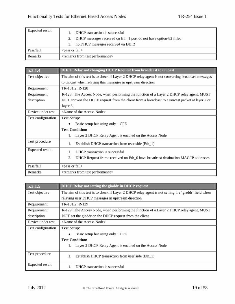
5.3.1.4 DHCP Relay not changing DHCP Request from broadcast to unicast
Test objective The aim of this test is to check if Layer 2 DHCP relay agent is not converting broadcast messages
to unicast when relaying this messages in upstream direction
Requirement TR-101i2: R-128
Requirement
description
R-128: The Access Node, when performing the function of a Layer 2 DHCP relay agent, MUST
NOT convert the DHCP request from the client from a broadcast to a unicast packet at layer 2 or
layer 3
Device under test <Name of the Access Node>
Test configuration Test Setup:
Basic setup but using only 1 CPE
Test Condition:
1. Layer 2 DHCP Relay Agent is enabled on the Access Node
Test procedure 1. Establish DHCP transaction from user side (Eth_1)
Expected result 1. DHCP transaction is successful
2. DHCP Request frame received on Eth_0 have broadcast destination MAC/IP addresses
Pass/fail <pass or fail>
Remarks <remarks from test performance>
5.3.1.5 DHCP Relay not setting the giaddr in DHCP request
Test objective The aim of this test is to check if Layer 2 DHCP relay agent is not setting the ‘giaddr’ field when
relaying user DHCP messages in upstream direction
Requirement TR-101i2: R-129
Requirement
description
R-129: The Access Node, when performing the function of a Layer 2 DHCP relay agent, MUST
NOT set the giaddr on the DHCP request from the client
Device under test <Name of the Access Node>
Test configuration Test Setup:
Basic setup but using only 1 CPE
Test Condition:
1. Layer 2 DHCP Relay Agent is enabled on the Access Node
Test procedure 1. Establish DHCP transaction from user side (Eth_1)
Expected result 1. DHCP transaction is successful

Functionality Tests for Ethernet Based Access Nodes TR-254 Issue 1
July 2012 © The Broadband Forum. All rights reserved 20 of 58
2. DHCP Request frame received on Eth_0 do not have ‘giaddr’ option filled
Pass/fail <pass or fail>
Remarks <remarks from test performance>
5.3.1.6 DHCP Relay discarding specific DHCP Discover and Requests packets
Test objective The aim of this test is to check if Layer 2 DHCP relay agent is discarding specific DHCP messages
Requirement TR-101i2: R-130
Requirement
description
R-130: The Access Node, when performing the function of a Layer 2 DHCP relay agent, MUST
be configurable per port to snoop all DHCP traffic and filter out those DISCOVER and REQUEST
packets from the access loop that have nonzero giaddr, and unicast request packets with a zero
ciaddr
Device under test <Name of the Access Node>
Test configuration Test Setup:
Basic setup but using only 1 CPE
Test Condition:
1. Layer 2 DHCP Relay Agent is enabled on the Access Node
Test procedure 1. Establish DHCP transaction from user side (Eth_1)
2. From user side (Eth_1) send DHCP Release
3. From user side (Eth_1) send DHCP Discovery and Request packets with nonzero ‘giaddr’
and destination broadcast MAC/IP address
4. From user side (Eth_1) send DHCP Request packets with zero ‘ciaddr’ and unicast
destination MAC/IP address of DHCP server
Expected result 1. In step 1 DHCP transaction is successful
2. In steps 3,4 all DHCP messages are discarded by Access Node and not appear on Eth_0
Pass/fail <pass or fail>
Remarks <remarks from test performance>
5.3.1.7 DHCP Relay discarding packets with option-82 from user
Test objective The aim of this test is to check if Layer 2 DHCP relay agent is discarding user DHCP messages
containing option-82
Requirement TR-101i2: R-131
Requirement
description
R-131: The Access Node, when performing the function of a Layer 2 DHCP relay agent, MUST
discard any DHCP request packet containing option-82 or giaddr and received from an untrusted
port.
Device under test <Name of the Access Node>
Test configuration Test Setup:
Basic setup but using only 1 CPE
Test Condition:
1. Layer 2 DHCP Relay Agent is enabled on the Access Node

Functionality Tests for Ethernet Based Access Nodes TR-254 Issue 1
July 2012 © The Broadband Forum. All rights reserved 21 of 58
Test procedure 1. Establish DHCP transaction from user side (Eth_1)
2. From user side (Eth_1) send DHCP Release
3. From user side (Eth_1) send DHCP Discovery and Request packets with broadcast
destination MAC/IP address and with nonzero option-82
4. From user side (Eth_1) send DHCP Request packets with unicast destination MAC/IP
address of DHCP server and with nonzero option-82
Expected result 1. In step 1 DHCP transaction is successful
2. In steps 3,4 all DHCP messages are discarded by the Access Node and not appear on
Eth_0
Pass/fail <pass or fail>
Remarks <remarks from test performance>
5.3.1.8 DHCP Relay forwarding DHCP requests
Test objective The aim of this test is to check if Layer 2 DHCP relay agent is forwarding user DHCP messages
only to uplink designated port
Requirement TR-101i2: R-132
Requirement
description
R-132: The Access Node, when performing the function of a Layer 2 DHCP relay agent, MUST
only forward DHCP requests to the upstream designated port(s) to prevent flooding or spoofing
Device under test <Name of the Access Node>
Test configuration Test Setup:
Basic setup
Test Condition:
1. Layer 2 DHCP Relay Agent is enabled on the Access Node for CPE_1 and CPE_2 - both
user ports are in the same VLAN_X (X – random value)
Test procedure 1. Establish DHCP transaction from user side (Eth_1)
Expected result 1. DHCP messages are received on Eth_0 (no messages received on Eth_2)
Pass/fail <pass or fail>
Remarks <remarks from test performance>
5.3.2 ARP Processing and IP Spoofing Prevention
5.3.2.1 Populating ARP table according to DHCP transaction
Test objective The aim of this test is to check if ARP table is populated by DHCP transactions
Requirement TR-101i2: R-134
Requirement
description
R-134: The Access Node SHOULD inspect upstream and downstream DHCP packets, discover
mapping of IP address to MAC address and access ports and populate its ARP table accordingly
Device under test <Name of the Access Node>
Test configuration Test Setup:
Basic setup

Functionality Tests for Ethernet Based Access Nodes TR-254 Issue 1
July 2012 © The Broadband Forum. All rights reserved 22 of 58
Test Condition:
1. Layer 2 DHCP Relay Agent is enabled on the Access Node
Test procedure 1. Establish DHCP transaction from user side (Eth_1 and Eth_2)
2. Check the Access Node’s ARP table
Expected result 1. In step 2 the Access Node’s ARP table have entries with IP and MAC for Eth_1 and
Eth_2
Pass/fail <pass or fail>
Remarks <remarks from test performance>
5.3.2.2 ARP Processing in downstream
Test objective The aim of this test is to check if ARP Processing works in downstream direction
Requirement TR-101i2: R-135
Requirement
description
R-135: The Access Node SHOULD ensure that downstream broadcast ARP requests are not sent
on access ports that do not have the associated requested IP address
Device under test <Name of the Access Node>
Test configuration Test Setup:
Basic setup
Test Condition:
1. Layer 2 DHCP Relay Agent is enabled on the Access Node
Test procedure 1. Establish DHCP transaction from user side (Eth_1 and Eth_2)
2. From Eth_0 send ARP Request for IP address corresponding to Eth_1
Expected result 1. In step 2 ARP Request not appear on Eth_2 port
2. In step 2 Eth_1 is responding for ARP Request. This message is received on Eth_0
Pass/fail <pass or fail>
Remarks <remarks from test performance>
5.3.2.3 IP Spoofing Prevention in case of DHCP
Test objective The aim of this test is to check if IP address spoofing prevention works and is properly populated
from DHCP transactions
Requirement TR-101i2: R-136
Requirement
description
R-136: The Access Node SHOULD provide a mechanism to prevent user IP address spoofing
Device under test <Name of the Access Node>
Test configuration Test Setup:
Basic setup but using only 1 CPE
Test Conditions:
1. Layer 2 DHCP Relay Agent is enabled on the Access Node
2. IP Spoofing Prevention is enabled on the Access Node

Functionality Tests for Ethernet Based Access Nodes TR-254 Issue 1
July 2012 © The Broadband Forum. All rights reserved 23 of 58
Test procedure 1. Establish DHCP transaction from user side (Eth_1)
2. From Eth_1 send traffic with source IP address assigned in step 1
3. From Eth_1 send traffic with source IP address different than in step 2
Expected result 1. In step 2 traffic is received on Eth_0
2. In step 3 traffic is discarded by the Access Node and not appear on Eth_0
Pass/fail <pass or fail>
Remarks <remarks from test performance>
5.3.2.4 IP Spoofing Prevention in case of static IP configuration
Test objective The aim of this test is to check if IP address spoofing prevention works in the case of static IP
configuration
Requirement TR-101i2: R-137
Requirement
description
R-137: The Access Node SHOULD be configurable with a list of IP addresses associated with
user port and VLAN for users having static IP configuration.
Device under test <Name of the Access Node>
Test configuration Test Setup:
Basic setup but using only 1 CPE
Test Conditions:
1. Layer 2 DHCP Relay Agent is enabled on the Access Node
2. IP Spoofing Prevention is enabled on the Access Node
3. For Eth_1 static IP address is configured on the Access Node
Test procedure 1. From Eth_1 send traffic with source IP address configured on the Access Node
2. From Eth_1 send traffic with source IP address different than in step 1
Expected result 1. In step 1 traffic is received on Eth_0
2. In step 2 traffic is discarded by the Access Node and not appear on Eth_0
Pass/fail <pass or fail>
Remarks <remarks from test performance>
5.4 Access Loop Identification and Characterization
5.4.1 DHCP Relay Agent
5.4.1.1 DHCP Relay Agent Circuit ID format
Test objective The aim of this test is to check format of Agent Circuit ID added by DHCP Relay Agent
Requirement TR-101i2: R-140
Requirement
description
R-140: The Access Node DHCP Relay Agent MUST be able to encode the access loop
identification in the “Agent Circuit ID” sub-option (sub-option 1). The encoding MUST uniquely
identify the Access Node and the access loop logical port on the Access Node on which the DHCP

Functionality Tests for Ethernet Based Access Nodes TR-254 Issue 1
July 2012 © The Broadband Forum. All rights reserved 24 of 58
message was received. The Agent Circuit ID contains a locally administered ASCII string
generated by the Access Node, representing the corresponding access loop logical port
(Uinterface). The actual syntax of the access loop identification in the Agent Circuit ID is
mandated in Section 3.9.3
Device under test <Name of the Access Node>
Test configuration Test Setup:
Basic setup
Test Conditions:
1. Layer 2 DHCP Relay Agent is configured on the Access Node with inserting Agent
Circuit ID sub-option
2. In sub-option Agent Circuit ID configure string which identify the Access Node and the
access loop port
Test procedure 1. Establish DHCP transaction from user side (Eth_1 and Eth_2)
Expected result 1. In step 1 DHCP Discovery and Request messages received on Eth_0 have sub-options
Agent Circuit ID as configured on the Access Node
2. In step 1 sub-options for Eth_1 and Eth_2 differs at least in port value
Pass/fail <pass or fail>
Remarks <remarks from test performance>
5.4.1.2 DHCP Relay Agent Remote ID format
Test objective The aim of this test is to check the format of the Remote ID added by the DHCP Relay Agent
Requirement TR-101i2: R-141
Requirement
description
R-141: The Access Node DHCP Relay Agent MUST have the option to use the “Agent Remote
ID” sub-option (sub-option 2) to further refine the access loop logical port identification. The
Agent Remote ID contains an a configurable string of 63 characters maximum that uniquely
identifies the user on the associated access loop on the Access Node on which the DHCP
Discovery message was received. The actual syntax of the user identification in the Agent Remote
ID is not specified in TR-254
Device under test <Name of the Access Node>
Test configuration Test Setup:
Basic setup
Test Condition:
1. Layer 2 DHCP Relay Agent is enabled on the Access Node
Test procedure 1. Configure the Remote ID fields inserted by the Access Node DHCP Relay Agent with
maximum lengths. Remote ID filled for Eth_1 and Eth_2 must uniquely identify the user
port
2. Establish DHCP transaction from user side (Eth_1 and Eth_2)
Expected result 1. In step 1 maximum possible to configured value is less than 64 characters
2. In step 2 DHCP Discovery and Request messages received on Eth_0 have sub-options

Functionality Tests for Ethernet Based Access Nodes TR-254 Issue 1
July 2012 © The Broadband Forum. All rights reserved 25 of 58
Remote ID as configured on the Access Node
3. In step 2 sub-options Remote ID for Eth_1 and Eth_2 differs at least in port value
Pass/fail <pass or fail>
Remarks <remarks from test performance>
5.4.2 PPPoE Intermediate Agent
5.4.2.1 PPPoE Intermediate Agent
Test objective The aim of this test is to check if the PPPoE Intermediate Agent works
Requirements TR-101i2: R-143, R-146
Requirement
description
The PPPoE Intermediate Agent intercepts all upstream PPPoE discovery stage packets, i.e. the
PADI, PADR and upstream PADT packets, but does not modify the source or destination MAC
address of these PPPoE discovery packets. Upon receipt of a PADI or PADR packet sent by the
PPPoE client, the Intermediate Agent adds a PPPoE Vendor-Specific TAG to the packet to be sent
upstream. The first four octets of the TAG_VALUE contain the vendor id “Broadband Forum”,
i.e. 0x000DE9. The remaining octets are used to convey the access loop identification and
characteristics
Device under test <Name of the Access Node>
Test configuration Test Setup:
Basic setup
Test Condition:
1. PPPoE Intermediate Agent is enabled on the Access Node
Test procedure 1. Establish PPPoE session from Eth_1
2. Send PPPoE PADT message from Eth_1
3. Send from Eth_1 PPPoE PADI and PADR messages that after adding access loop
identification will exceed MTU
Expected result 1. In step 1 PPPoE PADI and PADR messages received on Eth_0 are filled with option-105
with a vendor-specific sub-option with the structure of Figure 20/TR-101i2
2. In steps 1 and 2 PPPoE PADI, PADR, PADT messages received on Eth_0 have source
and destination MAC addresses the same as sent from Eth_1
3. In step 3 PPPoE PADI and PADR messages are dropped by the Access Node and not
appear on Eth_0
Pass/fail <pass or fail>
Remarks <remarks from test performance>
5.4.2.2 PPPoE Intermediate Agent Circuit ID format
Test objective The aim of this test is to check the format of the Agent Circuit ID added by the PPPoE
Intermediate Agent
Requirement TR-101i2: R-147
Requirement R-147: The Access Node MUST encode the access loop identification in the “Agent Circuit ID”

Functionality Tests for Ethernet Based Access Nodes TR-254 Issue 1
July 2012 © The Broadband Forum. All rights reserved 26 of 58
description suboption (sub-option 1). The encoding MUST uniquely identify the Access Node and the access
loop logical port on the Access Node on which the discovery stage PPPoE packet was received.
The Agent Circuit ID contains a locally administered ASCII string generated by the Access Node,
representing the corresponding access loop logical port (U-interface). The actual syntax of the
access loop identification in the Agent Circuit ID is mandated in Section 3.9.3.
Device under test <Name of the Access Node>
Test configuration Test Setup:
Basic setup
Test Conditions:
1. PPPoE Intermediate Agent is enabled on the Access Node
2. In sub-option ‘Agent Circuit ID’ configure string which identify the Access Node and the
access loop port
Test procedure 1. Establish PPPoE sessions from user side (Eth_1 and Eth_2)
Expected result 1. In step 1 PPPoE PADI and PADR messages received on Eth_0 have sub-options Agent
Circuit ID as configured on the Access Node
2. In step 1 sub-options for Eth_1 and Eth_2 differs at least in port value
Pass/fail <pass or fail>
Remarks <remarks from test performance>
5.4.2.3 PPPoE Intermediate Agent Remote ID format
Test objective The aim of this test is to check the format of the Agent Remote ID added by the PPPoE
Intermediate Agent
Requirement TR-101i2: R-148
Requirement
description
R-148: The Access Node MUST have the option to encode the user identification in the “Agent
Remote ID” sub-option (sub-option 2). The Agent Remote ID contains an configurable string of
63 characters maximum that uniquely identifies the user on the associated access loop logical port
on the Access Node on which the PPPoE discovery packet was received. The actual syntax of the
user identification in the Agent Remote ID is not specified in TR-254
Device under test <Name of the Access Node>
Test configuration Test Setup:
Basic setup
Test Condition:
1. PPPoE Intermediate Agent is enabled on the Access Node
Test procedure 1. Configure the Remote ID fields inserted by the Access Node PPPoE Intermediate Agent
with maximum lengths. Remote ID filled for Eth_1 and Eth_2 must uniquely identify the
user port
2. Establish PPPoE sessions from user side (Eth_1 and Eth_2)
Expected result 1. In step 1 maximum possible to configured value is less than 64 characters
2. In step 2 PPPoE PADI and PADR messages received on Eth_0 have sub-options Remote

Functionality Tests for Ethernet Based Access Nodes TR-254 Issue 1
July 2012 © The Broadband Forum. All rights reserved 27 of 58
ID as configured on the Access Node
3. In step 2 sub-options ‘Remote ID’ for Eth_1 and Eth_2 differs at least in port value
Pass/fail <pass or fail>
Remarks <remarks from test performance>
5.4.2.4 PPPoE Intermediate Agent replacing the Broadband Forum PPPoE vendor-specific tag
Test objective The aim of this test is to check if the PPPoE Intermediate Agent is replacing the vendor-specific
tag
Requirement TR-101i2: R-149
Requirement
description
R-149: The Access Node MUST replace the Broadband Forum PPPoE vendor-specific tag with
its own if the tag has also been provided by a PPPoE client
Device under test <Name of the Access Node>
Test configuration Test Setup:
Basic setup but using only 1 CPE
Test Conditions:
1. PPPoE client emulation is configured to insert Broadband Forum PPPoE vendor-specific
tag in it’s PADI and PADR messages
2. PPPoE Intermediate Agent is configured on the Access Node to replace
Broadband Forum PPPoE vendor-specific tag with it’s own
3. Vendor-specific tags on PPPoE client emulation and configured on the Access Node are
different
Test procedure 1. Establish PPPoE session from user side (Eth_1)
Expected result 1. PPPoE PADI and PADR messages received on Eth_0 have vendor-specific tag
sub-option as configured on the Access Node
Pass/fail <pass or fail>
Remarks <remarks from test performance>
5.4.3 Access Loop Identification Configuration and Syntax
5.4.3.1 Access Loop Identification Configuration and Syntax (DHCP Relay Agent)
Test objective The aim of this test is to check the maximum length of Agent Circuit ID field
Requirement TR-101i2: R-150
Requirement
description
R-150: The Agent Circuit ID field inserted by the Access Node DHCP Relay Agent and PPPoE
Intermediate Agent MUST NOT exceed 63 characters
Device under test <Name of the Access Node>
Test configuration Test Setup:
Basic setup but using only 1 CPE
Test Condition:
1. Layer 2 DHCP Relay Agent is enabled on the Access Node
Test procedure 1. Configure the Agent Circuit ID field inserted by the Access Node DHCP Relay Agent
with maximum length

Functionality Tests for Ethernet Based Access Nodes TR-254 Issue 1
July 2012 © The Broadband Forum. All rights reserved 28 of 58
2. Establish DHCP transaction from user side (Eth_1)
Expected result 1. In step 1 maximum possible to configured value is less than 64 characters
2. In step 2 DHCP Discovery and Request messages received on Eth_0 are filled with
sub-options with length as maximum configured
Pass/fail <pass or fail>
Remarks <remarks from test performance>
5.4.3.2 Access Loop Identification Configuration and Syntax (DHCP Relay Agent)
Test objective The aim of this test is to check the Agent Circuit ID default syntax
Requirements TR-101i2: R-151, R-152
Requirement
description
R-151: The value of the Agent Circuit ID MUST be explicitly configurable, per individual access
loop and logical port. When not explicitly configured, it MUST be automatically generated using
the default or flexible syntax described in following requirements
R-152: The Access Node DHCP Relay Agent and PPPoE Intermediate Agent MUST use the
following default syntax to automatically generate the Agent Circuit ID field, identifying access
loop logical ports as follows:
“Access-Node-Identifier atm slot/port:vpi.vci” (when ATM/DSL is used)
“Access-Node-Identifier eth slot/port[:vlan-id]” (when Ethernet[/DSL] is used)
In this syntax, Access-Node-Identifier MUST be a unique ASCII string (not using character
spaces). The Access-node-identifier, L2 type (ATM, ETH) field and the slot/port fields are
separated using a single space character. The slot identifier MUST NOT exceed 6 characters in
length and the port identifier MUST NOT exceed 3 characters in length and MUST use a ‘/’ as a
delimiter. The vpi, vci and vlan-id fields (when applicable) are related to a given access loop
(U-interface)
Device under test <Name of the Access Node>
Test configuration Test Setup:
Basic setup but using only 1 CPE
Test Conditions:
1. Layer 2 DHCP Relay Agent is enabled on the Access Node
2. Configure explicitly Agent Circuit ID per individual access loop and logical port or use
default syntax to automatically generate the Agent Circuit ID field inserted by the Access
Node DHCP Relay Agent
3. For Agent Circuit ID use one of the following scheme:
“Access-Node-Identifier atm slot/port:vpi.vci” (when ATM/DSL is used)
“Access-Node-Identifier eth slot/port[:vlan-id]” (when Ethernet[/DSL] is used)
Test procedure 1. Establish DHCP transaction from user side (Eth_1)
Expected result 1. In step 1 DHCP Discovery and Request messages received on Eth_0 are filled with
sub-option Agent Circuit ID according to presented above scheme
Pass/fail <pass or fail>

Functionality Tests for Ethernet Based Access Nodes TR-254 Issue 1
July 2012 © The Broadband Forum. All rights reserved 29 of 58
Remarks <remarks from test performance>
5.4.3.3 Access Loop Identification Configuration and Syntax (DHCP Relay Agent)
Test objective The aim of this test is to check Agent Circuit ID flexible syntax
Requirements TR-101i2: R-154, R-155
Requirement
description
R-154: It MUST be possible to override the default syntax of circuit IDs, and support
configuration of a more flexible syntax for the Agent Circuit ID, with flexibility in the choice of
elements used in the automated generation of circuit-IDs. Such syntax is unique per Access Node
R-155: The flexible syntax MUST allow the concatenation of 2 types of elements:
-Configured strings of ASCII characters. This will typically include characters used as separators
between variable fields (usually # . , ; / or space)
-Variable fields whose content is automatically generated by the Access Node. The minimum list
of those variable fields is given in the following table. Fields should include information which
does not vary over time for a given access loop.
Description of the variable Possible name
for the variable
Type of variable and max
length
Range of
values for the
variable
Logical name of the Access Node. Access_Node_ID Variable. Note that total length
of the overall agent-circuit-id
must not exceed 63 bytes
Chassis number in the access node Chassis Char(2) “0”..”99”
ONU number (Port) ONUID Char(3) “0”..”999”
Rack number in the access node Rack Char(2) “0”..”99”
Frame number in the rack Frame Char(2) “0”..”99”
Slot number in the chassis or rack or frame Slot Char(2) “0”..”99”
Sub-slot number Sub-slot Char(2) “0”..”99”
Port number in the slot Port Char(3) “0”..”999”
VPI on U interface in case of ATM over DSL VPI Char(4) “0”..”4095”
VCI on U interface in case of ATM over DSL VCI Char(5) “0”..”65535”
VLAN ID on U interface ( when applicable) Q-VID Char(4) ”0”..”4095”
S-VLAN ID on V interface S-VID Char(4) “0”,”4095”
C-VLAN ID on V interface C-VID Char(4) “0”,”4095”
Ethernet Priority bits on V interface Ethernet Priority Char(1) “0”..”7”
Device under test <Name of the Access Node>
Test configuration Test Setup:
Basic setup but using only 1 CPE
Test Condition:
1. Layer 2 DHCP Relay Agent is enabled on the Access Node
Test procedure 1. Configure the Agent Circuit ID field inserted by the Access Node DHCP Relay Agent to
use strings of ASCII characters: “#” “.” “,” “;” “/” “space” as separators and variable
fields whose content is automatically generated(if possible) by the Access Node, if not
supported, variable fields should be also configured explicitly
2. Establish DHCP transaction from user side (Eth_1)
Expected result 1. In step 1 each of characters is possible to be configured
2. In step 2 DHCP Discovery and Request messages received on Eth_0 are filled with
configured characters and variable fields are properly generated

Functionality Tests for Ethernet Based Access Nodes TR-254 Issue 1
July 2012 © The Broadband Forum. All rights reserved 30 of 58
Pass/fail <pass or fail>
Remarks <remarks from test performance>
5.4.3.4 Access Loop Identification Configuration and Syntax (PPPoE Intermediate Agent)
Test objective The aim of this test is to check the maximum length of the Agent Circuit ID field
Requirement TR-101i2: R-150
Requirement
description
R-150: The Agent Circuit ID field inserted by the Access Node DHCP Relay Agent and PPPoE
Intermediate Agent MUST NOT exceed 63 characters
Device under test <Name of the Access Node>
Test configuration Test Setup:
Basic setup but using only 1 CPE
Test Condition:
1. PPPoE Intermediate Agent is enabled on the Access Node
Test procedure 1. Configure the Agent Circuit ID field inserted by the Access Node PPPoE Intermediate
Agent with maximum length
2. Establish PPPoE session from user side (Eth_1)
Expected result 1. In step 1 maximum possible to configured value is less than 64 characters
2. In step 2 PPPoE PADI and PADR messages received on Eth_0 are filled with sub-options
with length as maximum configured
Pass/fail <pass or fail>
Remarks <remarks from test performance>
5.4.3.5 Access Loop Identification Configuration and Syntax (PPPoE Intermediate Agent)
Test objective The aim of this test is to check the Agent Circuit ID default syntax
Requirements TR-101i2: R-151, R-152
Requirement
description
R-151: The value of the Agent Circuit ID MUST be explicitly configurable, per individual access
loop and logical port. When not explicitly configured, it MUST be automatically generated using
the default or flexible syntax described in following requirements
R-152: The Access Node DHCP Relay Agent and PPPoE Intermediate Agent MUST use the
following default syntax to automatically generate the Agent Circuit ID field, identifying access
loop logical ports as follows:
“Access-Node-Identifier atm slot/port:vpi.vci” (when ATM/DSL is used)
“Access-Node-Identifier eth slot/port[:vlan-id]” (when Ethernet[/DSL] is used)
In this syntax, Access-Node-Identifier MUST be a unique ASCII string (not using character
spaces). The Access-node-identifier, L2 type (ATM, ETH) field and the slot/port fields are
separated using a single space character. The slot identifier MUST NOT exceed 6 characters in
length and the port identifier MUST NOT exceed 3 characters in length and MUST use a ‘/’ as a
delimiter. The vpi, vci and vlan-id fields (when applicable) are related to a given access loop
(U-interface)

Functionality Tests for Ethernet Based Access Nodes TR-254 Issue 1
July 2012 © The Broadband Forum. All rights reserved 31 of 58
Device under test <Name of the Access Node>
Test configuration Test Setup:
Basic setup but using only 1 CPE
Test Conditions:
1. PPPoE Intermediate Agent is enabled on the Access Node
2. Configure explicitly Agent Circuit ID per individual access loop and logical port or use
default syntax to automatically generate the Agent Circuit ID field inserted by the Access
Node PPPoE Intermediate Agent
3. For Agent Circuit ID use one of the following scheme:
“Access-Node-Identifier atm slot/port:vpi.vci” (when ATM/DSL is used)
“Access-Node-Identifier eth slot/port[:vlan-id]” (when Ethernet[/DSL] is used)
Test procedure 1. Establish PPPoE session from user side (Eth_1)
Expected result 1. In step 1 PPPoE PADI and PADR messages received on Eth_0 are filled with sub-option
Agent Circuit ID according to presented above scheme
Pass/fail <pass or fail>
Remarks <remarks from test performance>
5.4.3.6 Access Loop Identification Configuration and Syntax (PPPoE Intermediate Agent)
Test objective The aim of this test is to check Agent Circuit ID flexible syntax
Requirements TR-101i2: R-154, R-155
Requirement
description
R-154: It MUST be possible to override the default syntax of circuit IDs, and support configuration
of a more flexible syntax for the Agent Circuit ID, with flexibility in the choice of elements used in
the automated generation of circuit-IDs. Such syntax is unique per Access Node
R-155: The flexible syntax MUST allow the concatenation of 2 types of elements:
-Configured strings of ASCII characters. This will typically include characters used as separators
between variable fields (usually # . , ; / or space)
-Variable fields whose content is automatically generated by the Access Node. The minimum list
of those variable fields is given in the following table. Fields should include information which
does not vary over time for a given access loop
Description of the variable Possible name for
the variable
Type of variable and max
length
Range of
values for the
variable
Logical name of the Access Node. Access_Node_ID Variable. Note that total length
of the overall agent-circuit-id
must not exceed 63 bytes
Chassis number in the access node Chassis Char(2) “0”..”99”
ONU number (Port) ONUID Char(3) “0”..”999”
Rack number in the access node Rack Char(2) “0”..”99”
Frame number in the rack Frame Char(2) “0”..”99”
Slot number in the chassis or rack or frame Slot Char(2) “0”..”99”
Sub-slot number Sub-slot Char(2) “0”..”99”
Port number in the slot Port Char(3) “0”..”999”
VPI on U interface in case of ATM over
DSL
VPI Char(4) “0”..”4095”
VCI on U interface in case of ATM over VCI Char(5) “0”..”65535”

Functionality Tests for Ethernet Based Access Nodes TR-254 Issue 1
July 2012 © The Broadband Forum. All rights reserved 32 of 58
DSL
VLAN ID on U interface ( when
applicable)
Q-VID Char(4) ”0”..”4095”
S-VLAN ID on V interface S-VID Char(4) “0”,”4095”
C-VLAN ID on V interface C-VID Char(4) “0”,”4095”
Ethernet Priority bits on V interface Ethernet Priority Char(1) “0”..”7”
Device under test <Name of the Access Node>
Test configuration Test Setup:
Basic setup but using only 1 CPE
Test Condition:
1. PPPoE Intermediate Agent is enabled on the Access Node
Test procedure 1. Configure the Agent Circuit ID field inserted by the Access Node PPPoE Intermediate
Agent to use strings of ASCII characters: “#” “.” “,” “;” “/” “space” as separators and
variable fields whose content is automatically generated(if possible) by the Access Node,
if not supported variable fields should be also configured explicitly
2. Establish PPPoE session from side (Eth_1)
Expected result 1. In step 1 each of characters is possible to be configured
2. In step 2 PPPoE PADI and PADR messages received on Eth_0 are filled with configured
characters and variable fields which are properly generated
Pass/fail <pass or fail>
Remarks <remarks from test performance>
5.4.4 Access Loop Characteristics
5.4.4.1 Access Loop Characteristics configurable per port (DHCP Relay agent)
Test objective The aim of this test is to check if access loop characteristics are configurable per port
Requirement TR-101i2: R-156
Requirement
description
R-156: The Access Node MUST be able to insert the access loop characteristics via its PPPoE
intermediate agent and/or via its layer2 DHCP Relay agent. It MUST be possible to enable/disable
this function per port, depending on the type of user
Device under test <Name of the Access Node>
Test configuration Test Setup:
Basic setup
Test Conditions:
1. Layer 2 DHCP Relay Agent is enabled on the Access
2. Adding access loop characteristics by the Access Node is enabled for CPE_1 and disabled
for CPE_2
Test procedure 1. Establish DHCP transaction from user side (Eth_1)
2. Establish DHCP transaction from user side (Eth_2)
Expected result 1. In step 1 DHCP Discovery and Request messages received on Eth_0 and corresponding to
Eth_1 are filled with access loop characteristics
2. In step 2 DHCP Discovery and Request messages received on Eth_0 and corresponding to

Functionality Tests for Ethernet Based Access Nodes TR-254 Issue 1
July 2012 © The Broadband Forum. All rights reserved 33 of 58
Eth_2 port do not have access loop characteristics
Pass/fail <pass or fail>
Remarks <remarks from test performance>
5.4.4.2 Access Loop Characteristics (DHCP Relay agent)
Test objective The aim of this test is to check the access loop characteristics added by the Access Node
Requirements TR-101i2: R-142, R-159, R-160 and R-163
Requirement
description
R-142: The Access Node DHCP Relay Agent MUST support inserting vendor specific
information per RFC 4243
R-159: In all cases (PPPoE intermediate agent, DHCP-Relay), the access loop characteristics
information MUST be conveyed with a loop characteristics field structured with type-length value
sub-fields as described in RFC 4243 and again Appendix A - PPPoE Vendor-Specific BBF Tags
and Appendix B - DHCP Vendor Specific Options to Support Access Line Characteristics
R-160: Sync data rate values MUST be encoded as 32-bit binary values, describing the rate in
Kbps. Interleaving delays MUST be encoded as 32-bit binary values, describing the delay in
milliseconds. The complete set of sub-options is listed in the following table:
subopt. Message Type Information Reference
0x81 Actual data rate
Upstream
Actual data rate of an access loop ITU-T G.997
Section 7.5.2.1
0x82 Actual data rate
Downstream
Actual data rate of an access loop ITU-T G.997
Section 7.5.2.1
0x83 Minimum Data Rate
Upstream
Minimum data rate at which the loop
is set to operate
ITU-T G.997
Section 7.3.1.1.1
0x84 Minimum Data Rate
Downstream
Minimum data rate at which the loop
is set to operate
ITU-T G.997
Section 7.3.1.1.1
0x85 Attainable Data Rate
Upstream
Maximum data rate that can be
achieved.
ITU-T G.997
Section 7.5.1.12
and 7.5.1.13
0x86 Attainable Data Rate Downstream
Maximum data rate that can be achieved.
ITU-T G.997 Section 7.5.1.12
and 7.5.1.13
0x87 Maximum Data Rate
Upstream
Maximum data rate at which the loop
is set to operate
ITU-T G.997
Section 7.3.2.1.3
0x88 Maximum Data Rate
Downstream
Maximum data rate at which the loop
is set to operate
ITU-T G.997
Section 7.3.2.1.3
0x89 Minimum Data Rate
Upstream in low
power state
Minimum data rate at which the loop
is set to operate during the low power
state (L1/L2).
ITU-T G.997
Section 7.3.2.1.5
0x8A Minimum Data Rate
Downstream in low power state
Minimum data rate at which the loop
is set to operate during the low power state (L1/L2).
ITU-T G.997
Section 7.3.2.1.5
0x8B Maximum
[Interleaving] Delay
Upstream
Maximum one-way interleaving
delay
ITU-T G.997
Section 7.3.2.2
0x8C Actual [interleaving]
Delay Upstream
Value in milliseconds which
corresponds to the interleaver setting.
ITU-T G.997
section 7.5.2.3
0x8D Maximum Maximum one-way interleaving ITU-T G.997

Functionality Tests for Ethernet Based Access Nodes TR-254 Issue 1
July 2012 © The Broadband Forum. All rights reserved 34 of 58
[Interleaving] Delay Downstream
delay Section 7.3.2.2
0x8E Actual [interleaving]
Delay Downstream
Value in milliseconds which
corresponds to the interleaver setting.
ITU-T G.997
section 7.5.2.3
R-163: In the DHCP Relay case, the access loop characteristics information MUST be conveyed
by the DHCP option-82 field, with a vendor-specific sub-option, encoded according to RFC 4243,
with the enterprise number being the Broadband Forum enterprise code, i.e. 3561 in decimal
(0x0DE9 in hexadecimal), corresponding to the IANA “Broadband Forum” entry in the Private
Enterprise Numbers registry. Sub-options codes are described in Table 3
Device under test <Name of the Access Node>
Test configuration Test Setup:
Basic setup but using only 1 CPE
Test Condition:
1. Layer 2 DHCP Relay Agent is configured on the Access Node to insert all the access line
characteristics
Test procedure 1. Establish DHCP transaction from user side (Eth_1)
Expected result 1. In step 1 DHCP Discovery and Request messages received on Eth_0 are filled with
DHCP option-82 with all sub-options
2. In step 1 DHCP Discovery and Request messages received on Eth_0 are filled with
DHCP option-82 with a vendor-specific sub-option, with the enterprise number being the
Broadband Forum enterprise code, i.e. 3561 in decimal (0x0DE9 in hexadecimal). The
correct structure is presented in TR-101i2 Appendix B.
3. All sub-options in step 1 have correct values
Pass/fail <pass or fail>
Remarks <remarks from test performance>
5.4.4.3 Access Loop Characteristics configurable per port (PPPoE intermediate agent)
Test objective The aim of this test is to check if the access loop characteristics is configurable per port
Requirement TR-101i2: R-156
Requirement
description
R-156: The Access Node MUST be able to insert the access loop characteristics via its PPPoE
intermediate agent and/or via its layer2 DHCP Relay agent. It MUST be possible to enable/disable
this function per port, depending on the type of user
Device under test <Name of the Access Node>
Test configuration Test Setup:
Basic setup
Test Conditions:
1. PPPoE Intermediate Agent is enabled on the Access Node for CPE_1 and CPE_2
2. Adding access loop characteristics by the Access Node is enabled for CPE_1 and disabled
for CPE_2

Functionality Tests for Ethernet Based Access Nodes TR-254 Issue 1
July 2012 © The Broadband Forum. All rights reserved 35 of 58
Test procedure 1. Establish PPPoE session from user side (Eth_1)
2. Establish PPPoE session from user side (Eth_2)
Expected result 1. In step 1 PPPoE PADI and PADR messages received on Eth_0 and corresponding to
Eth_1 (CPE_1) port are filled with PPP option-105 (0x0105 in hex)with access loop
characteristics
2. In step 2 PPPoE PADI and PADR messages received on Eth_0 and corresponding to
Eth_2 (CPE_2) port do not have access loop characteristics
Pass/fail <pass or fail>
Remarks <remarks from test performance>
5.4.4.4 Access Loop Characteristics (PPPoE intermediate agent)
Test objective The aim of this test is to check the access loop characteristics added by Access Node
Requirements TR-101i2: R-159, R-160 and R-164
Requirement
description
R-159: In all cases (PPPoE intermediate agent, DHCP-Relay), the access loop characteristics
information MUST be conveyed with a loop characteristics field structured with type-length value
sub-fields as described in RFC 4243 and again Appendix A - PPPoE Vendor-Specific BBF Tags
and Appendix B - DHCP Vendor Specific Options to Support Access Line Characteristics
R-160: Sync data rate values MUST be encoded as 32-bit binary values, describing the rate in
Kbps. Interleaving delays MUST be encoded as 32-bit binary values, describing the delay in
milliseconds. The complete set of sub-options is listed in the following table:
subopt. Message Type Information Reference
0x81 Actual data rate
Upstream
Actual data rate of an access loop ITU-T G.997
Section 7.5.2.1
0x82 Actual data rate
Downstream
Actual data rate of an access loop ITU-T G.997
Section 7.5.2.1
0x83 Minimum Data Rate
Upstream
Minimum data rate at which the loop
is set to operate
ITU-T G.997
Section 7.3.1.1.1
0x84 Minimum Data Rate Downstream
Minimum data rate at which the loop is set to operate
ITU-T G.997 Section 7.3.1.1.1
0x85 Attainable Data Rate
Upstream
Maximum data rate that can be
achieved.
ITU-T G.997
Section 7.5.1.12
and 7.5.1.13
0x86 Attainable Data Rate
Downstream
Maximum data rate that can be
achieved.
ITU-T G.997
Section 7.5.1.12
and 7.5.1.13
0x87 Maximum Data Rate
Upstream
Maximum data rate at which the loop
is set to operate
ITU-T G.997
Section 7.3.2.1.3
0x88 Maximum Data Rate
Downstream
Maximum data rate at which the loop
is set to operate
ITU-T G.997
Section 7.3.2.1.3
0x89 Minimum Data Rate Upstream in low
power state
Minimum data rate at which the loop is set to operate during the low power
state (L1/L2).
ITU-T G.997 Section 7.3.2.1.5
0x8A Minimum Data Rate
Downstream in low
power state
Minimum data rate at which the loop
is set to operate during the low power
state (L1/L2).
ITU-T G.997
Section 7.3.2.1.5

Functionality Tests for Ethernet Based Access Nodes TR-254 Issue 1
July 2012 © The Broadband Forum. All rights reserved 36 of 58
0x8B Maximum [Interleaving] Delay
Upstream
Maximum one-way interleaving delay
ITU-T G.997 Section 7.3.2.2
0x8C Actual [interleaving]
Delay Upstream
Value in milliseconds which
corresponds to the interleaver setting.
ITU-T G.997
section 7.5.2.3
0x8D Maximum
[Interleaving] Delay
Downstream
Maximum one-way interleaving
delay
ITU-T G.997
Section 7.3.2.2
0x8E Actual [interleaving]
Delay Downstream
Value in milliseconds which
corresponds to the interleaver setting.
ITU-T G.997
section 7.5.2.3
R-164: In the PPPoE case, the access loop characteristics information MUST be conveyed by an
extension of the Broadband-Forum vendor-specific PPPoE tag defined in Section 3.9.2, using
additional sub-options with codes as described in Table 3. See Appendix A - PPPoE Vendor-
Specific BBF Tags for more detailed sub-option encoding
Device under test <Name of the Access Node>
Test configuration Test Setup:
Basic setup but using only 1 CPE
Test Condition:
1. PPPoE Intermediate Agent is configured on the Access Node to insert all the access line
characteristics
Test procedure 1. Establish PPPoE session from user side (Eth_1)
Expected result 1. In step 1 PPPoE PADI and PADR messages received on Eth_0 are filled with PPPoE
option-105 (0x0105 in hex) with all sub-options
2. All sub-options in step 1 have correct values (list of checked sub-options should be
mentioned in this place)
Pass/fail <pass or fail>
Remarks <remarks from test performance>
5.5 Baseline Multicast Description
5.5.1 Per User-facing Port and VLAN Requirements
5.5.1.1 Processing of user-initiated IGMP messages
Test objective The aim of the test is to check if the user-initiated IGMP messages processing works
Requirement TR-101i2: R-238
Requirement
description
R-238: The Access Node MUST support the identification and processing of user-initiated IGMP
messages. When this function is disabled on a port and/or VLAN, these messages are transparently
forwarded
Device under test <Name of the Access Node>
Test configuration Test Setup:
Basic setup
Test Conditions:

Functionality Tests for Ethernet Based Access Nodes TR-254 Issue 1
July 2012 © The Broadband Forum. All rights reserved 37 of 58
1. CPE_1 and CPE_2 are members of VLAN_X (X, Y – 2 different random values)
2. IGMP processing is enabled in VLAN_X and for port facing CPE_1
3. IGMP processing is disabled for port facing CPE_2 (if action not configurable per port,
configure CPE_2 in another VLAN_Y)
4. Several multicast groups are configured on the Access Node
Test procedure 1. Downstream multicast traffic is generated
2. From user side (Eth_1) send IGMP join packets matching Groups Addresses configured
on the Access Node
3. From user side (Eth_1) send IGMP leave packets matching Groups Addresses configured
on the Access Node
4. From user side (Eth_2) send IGMP join and leave packets
Expected result 1. After step 2 multicast streams are received on Eth_1
2. After step 3 no multicast stream is received on Eth_1
3. In step 4 IGMP messages are received on Eth_0
Pass/fail <pass or fail>
Remarks <remarks from test performance>
5.5.1.2 Dropping IGMP messages received on user port
Test objective The aim of the test is to check if dropping of all IGMP messages received on user port works
Requirement TR-101i2: R-239
Requirement
description
R-239: The Access Node MUST support dropping of all IGMP messages received on a user port
and/or VLAN
Device under test <Name of the Access Node>
Test configuration Test Setup:
Basic setup
Test Conditions:
1. CPE_1 and CPE_2 are members of multicast VLAN_X (X - random value)
2. IGMP processing is enabled on VLAN_X
3. Several multicast groups are configured on the Access Node
4. For CPE_2 Access Node is configured to drop all IGMP messages received (if action not
configurable per port, configure CPE_2 in another VLAN)
Test procedure 1. Downstream multicast traffic is generated
2. From user side (Eth_1) send IGMP join messages
3. From user side (Eth_1) send IGMP leave messages
4. From user side (Eth_2) send IGMP join messages
5. From user side (Eth_2) send IGMP leave messages
Expected result 1. After step 2 multicast stream are received on Eth_1
2. After step 3 no multicast stream is received on Eth_1
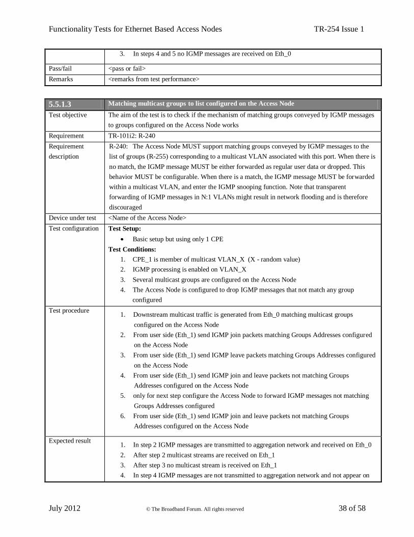
Functionality Tests for Ethernet Based Access Nodes TR-254 Issue 1
July 2012 © The Broadband Forum. All rights reserved 38 of 58
3. In steps 4 and 5 no IGMP messages are received on Eth_0
Pass/fail <pass or fail>
Remarks <remarks from test performance>
5.5.1.3 Matching multicast groups to list configured on the Access Node
Test objective The aim of the test is to check if the mechanism of matching groups conveyed by IGMP messages
to groups configured on the Access Node works
Requirement TR-101i2: R-240
Requirement
description
R-240: The Access Node MUST support matching groups conveyed by IGMP messages to the
list of groups (R-255) corresponding to a multicast VLAN associated with this port. When there is
no match, the IGMP message MUST be either forwarded as regular user data or dropped. This
behavior MUST be configurable. When there is a match, the IGMP message MUST be forwarded
within a multicast VLAN, and enter the IGMP snooping function. Note that transparent
forwarding of IGMP messages in N:1 VLANs might result in network flooding and is therefore
discouraged
Device under test <Name of the Access Node>
Test configuration Test Setup:
Basic setup but using only 1 CPE
Test Conditions:
1. CPE_1 is member of multicast VLAN_X (X - random value)
2. IGMP processing is enabled on VLAN_X
3. Several multicast groups are configured on the Access Node
4. The Access Node is configured to drop IGMP messages that not match any group
configured
Test procedure 1. Downstream multicast traffic is generated from Eth_0 matching multicast groups
configured on the Access Node
2. From user side (Eth_1) send IGMP join packets matching Groups Addresses configured
on the Access Node
3. From user side (Eth_1) send IGMP leave packets matching Groups Addresses configured
on the Access Node
4. From user side (Eth_1) send IGMP join and leave packets not matching Groups
Addresses configured on the Access Node
5. only for next step configure the Access Node to forward IGMP messages not matching
Groups Addresses configured
6. From user side (Eth_1) send IGMP join and leave packets not matching Groups
Addresses configured on the Access Node
Expected result 1. In step 2 IGMP messages are transmitted to aggregation network and received on Eth_0
2. After step 2 multicast streams are received on Eth_1
3. After step 3 no multicast stream is received on Eth_1
4. In step 4 IGMP messages are not transmitted to aggregation network and not appear on

Functionality Tests for Ethernet Based Access Nodes TR-254 Issue 1
July 2012 © The Broadband Forum. All rights reserved 39 of 58
Eth_0
5. After step 4 no multicast stream is received on Eth_1
6. In step 6 IGMP messages are transparently transmitted to aggregation network and
received on Eth_0
Pass/fail <pass or fail>
Remarks <remarks from test performance>
5.5.1.4 Injecting multicast traffic from user-port
Test objective The aim of the test is to check if the mechanism of stopping user ports from injecting multicast
traffic works
Requirement TR-101i2: R-242
Requirement
description
R-242: The Access Node MUST be configurable per port and/or VLAN to stop user ports
injecting multicast traffic to the aggregation network
Device under test <Name of the Access Node>
Test configuration Test Setup:
Basic setup
Test Conditions:
1. CPE_1 and CPE_2 are members of multicast VLAN_X (X - random value)
2. IGMP processing is enabled on VLAN_X
3. Several multicast groups are configured on the Access Node
4. For CPE_1 the Access Node is configured to stop user ports injecting multicast traffic to
the aggregation network
5. For CPE_2 the Access Node is configured to allow user ports injecting multicast traffic to
the aggregation network (if action not configurable per port, configure CPE_2 in another
VLAN)
Test procedure 1. From user side (Eth_1) send multicast stream
2. From user side (Eth_2) send multicast stream
Expected result 1. In step 1 no multicast stream is received on Eth_0 and Eth_2
2. In step 2 multicast stream is received on Eth_0
Pass/fail <pass or fail>
Remarks <remarks from test performance>
5.5.1.5 Discarding IGMP queries received from user-facing port
Test objective The aim of the test is to check if the mechanism of discarding IGMP queries works
Requirement TR-101i2: R-243
Requirement
description
R-243: The Access Node MUST be able to discard IGMP queries received from user-facing ports
on a multicast VLAN
Device under test <Name of the Access Node>
Test configuration Test Setup:

Functionality Tests for Ethernet Based Access Nodes TR-254 Issue 1
July 2012 © The Broadband Forum. All rights reserved 40 of 58
Basic setup
Test Conditions:
1. CPE_1 and CPE_2 are members of multicast VLAN_X (X random value)
2. IGMP processing is enabled on VLAN_X
3. Several multicast groups are configured on the Access Node
Test procedure 1. From user side (Eth_1) send IGMP query packets
Expected result 1. No IGMP query messages are received on Eth_0 and Eth_2
Pass/fail <pass or fail>
Remarks <remarks from test performance>
5.5.1.6 Limiting IGMP messages received from user-facing port
Test objective The aim of the test is to check if the mechanism of limiting IGMP messages works
Requirement TR-101i2: R-244
Requirement
description
R-244: The Access Node MUST be able to rate limit IGMP messages received from user-facing
ports on a multicast VLAN
Device under test <Name of the Access Node>
Test configuration Test Setup:
Basic setup
Test Conditions:
1. CPE_1 and CPE_2 are members of multicast VLAN_X (X random value)
2. IGMP processing is enabled on VLAN_X
3. Several multicast groups are configured on the Access Node
4. The Access Node is configured to limit IGMP messages received from user-facing ports
Test procedure 1. Downstream multicast traffic is generated from Eth_0 matching multicast groups
configured on the Access Node
2. From Eth_1 send IGMP join and leave packets with high rate
Expected result 1. In step 2 IGMP messages are transmitted to aggregation network and received on Eth_0
with lower rate
Pass/fail <pass or fail>
Remarks <remarks from test performance>
5.5.2 Access Node Configuration Requirements
5.5.2.1 Multicast VLAN member configurable per port
Test objective The aim of the test is to check if it is possible to configure a specific port as a member of multicast
VLAN
Requirement TR-101i2: R-254
Requirement
description
R-254: The Access Node MUST support configuring which user ports are members of a
multicast VLAN

Functionality Tests for Ethernet Based Access Nodes TR-254 Issue 1
July 2012 © The Broadband Forum. All rights reserved 41 of 58
Device under test <Name of the Access Node>
Test configuration Test Setup:
Basic setup
Test Conditions:
1. CPE_1 is member of multicast VLAN_X and CPE_2 is member of VLAN_Y (X,Y – 2
different random values)
2. IGMP processing is enabled on VLAN_X and disabled on VLAN_Y
3. Several multicast groups are configured on the Access Node
Test procedure 1. Downstream multicast traffic for each multicast group is generated from Eth_0 on both
VLAN_X and VLAN_Y
2. From user side (Eth_1 and Eth_2) send IGMP join messages
3. From user side (Eth_1 and Eth_2) send IGMP leave messages
Expected result 1. After step 2 multicast streams are received on Eth_1
2. After step 2 IGMP snooping table is filled only with user Eth_1 entries
Pass/fail <pass or fail>
Remarks <remarks from test performance>
5.5.2.2 Source address matching
Test objective The aim of the test is to check if the configuration of IP multicast groups based on source address
matching is possible on the Access Node
Requirement TR-101i2: R-255
Requirement
description
R-255: The Access Node MUST allow the configuration of IP multicast groups or ranges of
multicast groups per multicast VLAN based on:
• Source address matching
• Group address matching
Device under test <Name of the Access Node>
Test configuration Test Setup:
Basic setup but using only 1 CPE
Test Conditions:
1. CPE_1 is member of multicast VLAN_X (X random value)
2. IGMP processing is enabled on VLAN_X
3. The Access Node is configured to check the source addresses of multicast groups
generated from Eth_0
4. The Access Node is configured with several source addresses of multicast groups
Test procedure 1. Downstream multicast streams matching source addresses configured on the Access Node
is generated from Eth_0
2. From Eth_1 send IGMP join messages to the groups send from Eth_0
3. From Eth_1 send IGMP leave messages to the groups send from Eth_0
4. Downstream multicast streams not matching source addresses configured on the Access

Functionality Tests for Ethernet Based Access Nodes TR-254 Issue 1
July 2012 © The Broadband Forum. All rights reserved 42 of 58
Node is generated from Eth_0
5. From Eth_1 send IGMP join messages to the groups send from Eth_0
Expected result 1. After step 2 multicast streams are received on Eth_1
2. After step 5 no multicast streams are received on Eth_1
Pass/fail <pass or fail>
Remarks <remarks from test performance>
5.5.2.3 Group address matching
Test objective The aim of the test is to check if the configuration of IP multicast groups based on group address
matching is possible on the Access Node
Requirement TR-101i2: R-255
Requirement
description
R-255: The Access Node MUST allow the configuration of IP multicast groups or ranges of
multicast groups per multicast VLAN based on:
• Source address matching
• Group address matching
Device under test <Name of the Access Node>
Test configuration Test Setup:
Basic setup but using only 1 CPE
Test Conditions:
1. CPE_1 is member of multicast VLAN_X (X random value)
2. IGMP processing is enabled on VLAN_X
3. The Access Node is configured to check the group addresses of multicast streams
generated from Eth_0
4. The Access Node is configured with several group addresses of multicast streams
Test procedure 1. Downstream multicast streams matching group addresses configured on the Access Node
is generated from Eth_0
2. From Eth_1 send IGMP join messages to the groups send from Eth_0
3. From Eth_1 send IGMP leave messages to the groups send from Eth_0
4. Downstream multicast streams not matching group addresses configured on the Access
Node is generated from Eth_0
5. From Eth_1 send IGMP join messages to the groups send from Eth_0
Expected result 1. After step 2 multicast streams are received on Eth_1
2. After step 5 no multicast stream is received on Eth_1
Pass/fail <pass or fail>
Remarks <remarks from test performance>
5.5.2.4 Maximum number of simultaneous multicast groups
Test objective The aim of the test is to check if the mechanism of limiting simultaneous multicast groups works
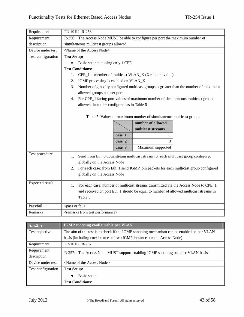
Functionality Tests for Ethernet Based Access Nodes TR-254 Issue 1
July 2012 © The Broadband Forum. All rights reserved 43 of 58
Requirement TR-101i2: R-256
Requirement
description
R-256: The Access Node MUST be able to configure per port the maximum number of
simultaneous multicast groups allowed
Device under test <Name of the Access Node>
Test configuration Test Setup:
Basic setup but using only 1 CPE
Test Conditions:
1. CPE_1 is member of multicast VLAN_X (X random value)
2. IGMP processing is enabled on VLAN_X
3. Number of globally configured multicast groups is greater than the number of maximum
allowed groups on user port
4. For CPE_1 facing port values of maximum number of simultaneous multicast groups
allowed should be configured as in Table 5
Table 5. Values of maximum number of simultaneous multicast groups
number of allowed
multicast streams
case_1 1
case_2 3
case_3 Maximum supported
Test procedure 1. Send from Eth_0 downstream multicast stream for each multicast group configured
globally on the Access Node
2. For each case: from Eth_1 send IGMP join packets for each multicast group configured
globally on the Access Node
Expected result 1. For each case: number of multicast streams transmitted via the Access Node to CPE_1
and received on port Eth_1 should be equal to number of allowed multicast streams in
Table 5
Pass/fail <pass or fail>
Remarks <remarks from test performance>
5.5.2.5 IGMP snooping configurable per VLAN
Test objective The aim of the test is to check if the IGMP snooping mechanism can be enabled on per VLAN
basis (including coexistences of two IGMP instances on the Access Node)
Requirement TR-101i2: R-257
Requirement
description R-257: The Access Node MUST support enabling IGMP snooping on a per VLAN basis
Device under test <Name of the Access Node>
Test configuration Test Setup:
Basic setup
Test Conditions:

Functionality Tests for Ethernet Based Access Nodes TR-254 Issue 1
July 2012 © The Broadband Forum. All rights reserved 44 of 58
1. CPE_1 is member of multicast VLAN_X and CPE_2 is member of multicast VLAN_Y
(X,Y – 2 different random values)
2. IGMP snooping is enabled on VLAN_X and on VLAN_Y
3. Several multicast groups are configured on the Access Node for both VLAN_X and
VLAN_Y
Test procedure 1. Downstream multicast traffic for each multicast group is generated from Eth_0 on both
VLAN_X and VLAN_Y
2. From user side (Eth_1) send IGMP join messages
3. From user side (Eth_2) send IGMP join messages
4. From user side (Eth_1) send IGMP leave messages
5. From user side (Eth_2) send IGMP leave messages
Expected result 1. In step 2 IGMP join messages are transmitted to aggregation network and received on
Eth_0 with VLAN_X, no messages received on Eth_0 with VLAN_Y
2. After step 2 multicast streams are received on Eth_1
3. In step 3 IGMP join messages are transmitted to aggregation network and received on
Eth_0 with VLAN_Y, no messages received on Eth_0 with VLAN_X
4. After step 3 multicast streams are received on Eth_2
5. After step 3 IGMP snooping table of VLAN_X is filled only with user Eth_1 entries
6. After step 3 IGMP snooping table of VLAN_Y is filled only with user Eth_2 entries
7. In step 4 IGMP leave messages are transmitted to aggregation network and received on
Eth_0 with VLAN_X, no messages received on Eth_0 with VLAN_Y
8. In step 5 IGMP leave messages are transmitted to aggregation network and received on
Eth_0 with VLAN_Y, no messages received on Eth_0 with VLAN_X
9. After step 4 no multicast stream is received on Eth_1
10. After step 5 no multicast stream is received on Eth_2
Pass/fail <pass or fail>
Remarks <remarks from test performance>

Functionality Tests for Ethernet Based Access Nodes TR-254 Issue 1
July 2012 © The Broadband Forum. All rights reserved 45 of 58
6 Test cases covering requirements from TR-177
6.1 VLANs
6.1.1 Ethertype filters
Test objective The aim of the test is to check Ethertype filtering functionality
Requirement TR-177: R-02
Requirement
description
R-02: The Access Node MUST be able to assign an Ethertype filter to a given port.
At least the following types MUST be supported
IPv6oE (Ethertype = 0x86DD) – note: ICMPv6 is identified by a Next Header value of
58 in the immediately preceding IPv6 header
PPPoE (Ethertype = 0x8863 and 0x8864)
IPv4oE (Ethertype = 0x0800)
ARP (Ethertype = 0x0806)
Note that this is an augmentation of R-26/TR-101 with the IPv6oE Ethertype.
Device under test <Name of the Access Node>
Test configuration Test Setup:
Basic setup but using only 1 CPE
Test Condition:
1. On the Access Node for each test, one allowed flow is configured according to Table 6
Table 6. Ethertype filters
Test
Allowed
flow Ethertype
case_1 1 0x86DD
case_2 2 0x8863, 0x8864
case_3 3 0x0800, 0x0806
Test procedure 1. From Eth_1 send 3 flows
2. For each test case configure Ethertype filter according to Table 6
Expected result 1. In each test case only configured Ethertype is received on Eth_0 and all other flows are
discarded by the Access Node.
Pass/fail <pass or fail>
Remarks <remarks from test performance>
6.2 QoS Traffic Classification and Class of Service Based Forwarding
6.2.1 P-bit upstream marking
Test objective The aim of the test is to check upstream P-bit marking according to: user port, VLAN ID and
received IPv6 Traffic Class value
Requirement TR-177: R-04
Requirement
description
R-04: The Access Node SHOULD support deriving the P-bit markings in the upstream direction
based on an arbitrary combination of: user port, VLAN ID and received IPv6 Traffic Class value.

Functionality Tests for Ethernet Based Access Nodes TR-254 Issue 1
July 2012 © The Broadband Forum. All rights reserved 46 of 58
Device under test <Name of the Access Node>
Test configuration Test Setup:
Basic setup
Test Conditions:
1. Upstream p-bit marking/remarking is configured according to Table 7
2. VID1, VID2, Pbit1, Pbit2, Pbit3, TC1, TC2 are random values
Table 7. P-bit marking
Test Flow
U-interface V-interface
User
Port Q-VID p-bit
IPv6
Traffic Class S-VID p-bit
case_1 1 1 VID1 Pbit1 TC1 VID1 Pbit2
2 1 VID2 Pbit1 TC1 VID2 Pbit3
case_2 3 1 VID1 Pbit1 TC1 VID1 Pbit2
4 1 VID1 Pbit1 TC2 VID1 Pbit3
case_3 5 1 VID1 Pbit1 TC1 VID1 Pbit2
6 2 VID1 Pbit1 TC1 VID1 Pbit3
Test procedure 1. For each test case send 2 flows according to Table 7
Expected result 1. In each test case flows received on Eth_0 are marked with p-bit according to Table 7
Pass/fail <pass or fail>
Remarks <remarks from test performance>
6.3 IPv6 Interworking Functions
6.3.1 DHCPv6 Processing
6.3.1.1 Lightweight DHCPv6 Relay on per VLAN basis
Test objective The aim of the test is possibility of configuring Lightweight DHCPv6 Relay on per VLAN basis
Requirements TR-177: R-05, R-06
Requirement
description
R-05: The Access Node MUST be able to function as a Lightweight DHCPv6 Relay Agent
(LDRA) according to draft-ietf-dhc-dhcpv6-ldra
R-06: The Access Node MUST support enabling/disabling the LDRA function for all ports
associated with specific S-TAGs
Device under test <Name of the Access Node>
Test configuration Test Setup:
Basic setup
Test Condition:
1. LDRA function is enabled for VLAN_X (CPE_1) and disables for VLAN_Y (CPE_2);
X,Y are two different are random values
Test procedure 1. Establish DHCPv6 transaction from Eth_1
2. Establish DHCPv6 transaction from Eth_2
Expected result 1. In step 1 all DHCPv6 messages received on Eth_0 within VLAN_X are relayed
(msg-type is equal to RELAY-FORWARD, link-address field is set to Unspecified
Address (::) and include the Interface-ID option).

Functionality Tests for Ethernet Based Access Nodes TR-254 Issue 1
July 2012 © The Broadband Forum. All rights reserved 47 of 58
2. In step 2 all DHCPv6 messages are received on Eth_0 within VLAN_Y are transparently
forwarded without being relayed
Pass/fail <pass or fail>
Remarks <remarks from test performance>
6.3.1.2 Interface-ID Option added by LDRA
Test objective The aim of the test is to check if LDRA is adding the Interface-ID Option to DHCPv6 Relay-
forward messages
Requirement TR-177: R-07
Requirement
description
R-07: The Access Node MUST, when performing the function of an LDRA, be able to encode the
access loop identification in the Interface-Id Option (option 18, defined In RFC 3315 [14]) and
add the option to the DHCPv6 Relay-forward messages sent to the BNG, which acts as a DHCPv6
server or a DHCPv6 Relay Agent
Device under test <Name of the Access Node>
Test configuration Test Setup:
Basic setup but using only 1 CPE
Test Condition:
1. LDRA function is configured to add Interface-Id option with the access loop
identification
Test procedure 1. Establish DHCPv6 transaction from Eth_1
Expected result 1. In step 1 all DHCPv6 messages received on Eth_0 have Interface-Id Option (option 18)
filled with access loop identification
Pass/fail <pass or fail>
Remarks <remarks from test performance>
6.3.1.3 Format of Interface-ID option
Test objective The aim of the test is to check the format of the Interface-ID option added by LDRA
Requirement TR-177: R-08
Requirement
description
R-08: When adding the Interface-Id, the encoding MUST uniquely identify the Access Node and
the access loop logical port on the Access Node on which the DHCPv6 message was received. The
Interface-Id contains a locally administered ASCII string generated by the Access Node,
representing the corresponding access loop logical port (U interface). The actual syntax of the
access loop identification in the Interface-Id is identical to the syntax defined in Section 3.9.3/TR-
101 and Section 5.7/TR-156
Device under test <Name of the Access Node>
Test configuration Test Setup:
Basic setup but using only 1 CPE
Test Condition:
1. LDRA function is configured to add Interface-Id option

Functionality Tests for Ethernet Based Access Nodes TR-254 Issue 1
July 2012 © The Broadband Forum. All rights reserved 48 of 58
Test procedure 1. On the Access Node configure Interface-Id in one of the following ways:
“Access-Node-Identifier atm slot/port:vpi.vci” (when ATM/DSL is used)
“Access-Node-Identifier eth slot/port[:vlan-id]” (when Ethernet/DSL is used)
2. Establish DHCPv6 transaction from Eth_1
Expected result 1. In step 1 Interface-Id is possible to be configured
2. In step 2 all DHCPv6 messages received on Eth_0 have Interface-Id Option (option 18) as
configured in step 1
Pass/fail <pass or fail>
Remarks <remarks from test performance>
6.3.1.4 Relay Agent Remote-Id Option added by LDRA
Test objective The aim of the test is to check if LDRA is adding the Relay Agent Remote-Id Option to DHCPv6
Relay-forward messages
Requirement TR-177: R-09
Requirement
description
R-09: The Access Node MUST, when performing the function of an LDRA, be able to add the
Relay Agent Remote-Id Option (option 37, defined in RFC 4649 [16]) to the DHCPv6
Relay-forward messages sent to the BNG, which acts as a Delegating Router and/or a DHCPv6
Relay Agent
Device under test <Name of the Access Node>
Test configuration Test Setup:
Basic setup
Test Condition:
1. LDRA function is configured to add Relay Agent Remote-Id Option (option 37)
Test procedure 1. Establish DHCPv6 transaction from Eth_1
Expected result 1. In step 1 all DHCPv6 messages received on Eth_0 have Relay Agent Remote-Id Option
(option 37) as configured
2. In step 1 no DHCPv6 messages are received on Eth_2
Pass/fail <pass or fail>
Remarks <remarks from test performance>
6.3.1.5 Format of Relay Agent Remote-ID option
Test objective The aim of the test is to check the format of the Relay Agent Remote-Id option added by LDRA
Requirement TR-177: R-10
Requirement
description
R-10: When adding the Relay Agent Remote-Id, the Access Node MUST set the remote-id field
with a globally unique value that MUST be configurable by the Service Provider (for instance to
uniquely identify the user on the associated access loop on the Access Node on which the
DHCPv6 Solicit message was received). The actual syntax of the user identification in the Relay
Agent Remote-Id is left unspecified in this Technical Report

Functionality Tests for Ethernet Based Access Nodes TR-254 Issue 1
July 2012 © The Broadband Forum. All rights reserved 49 of 58
Device under test <Name of the Access Node>
Test configuration Test Setup:
Basic setup
Test Condition:
1. LDRA function is configured to add Remote-Id Option with remote-id field that uniquely
identify the user on the associated access loop (CPE_1 and CPE_2)
Test procedure 1. Establish DHCPv6 transaction from Eth_1 and Eth_2
Expected result 1. In step 1 DHCPv6 messages received on Eth_0 have Relay Agent Remote-Id Option
(option 37) that uniquely identify user ports facing CPE_1 and CPE_2
Pass/fail <pass or fail>
Remarks <remarks from test performance>
6.3.1.6 Enterprise-number field in Relay Agent Remote-Id option
Test objective The aim of the test is to check the enterprise-number field in the Relay Agent Remote-Id option
added by LDRA
Requirement TR-177: R-11
Requirement
description
R-11: When adding the Relay Agent Remote-Id, the Access Node MUST set the enterprise-
number field as follows:
In the case where the operator did not provide the enterprise-number as part of the
configuration of the Relay Agent Remote-Id option, the enterprise number MUST be set to
the Broadband Forum enterprise code, i.e. 3561 in decimal (0x0DE9 in hexadecimal),
corresponding to the IANA “ADSL Forum” entry in the Private Enterprise Numbers registry.
In the case where the operator did provide the enterprise-number as part of the configuration
of the Relay Agent Remote-Id option, the enterprise number MUST be set to the value
provided by the operator
Device under test <Name of the Access Node>
Test configuration Test Setup:
Basic setup but using only 1 CPE
Test Condition:
1. LDRA function is configured to add Remote-Id Option
Test procedure 1. Configure enterprise-number as Broadband Forum enterprise code
2. Establish DHCPv6 transaction from Eth_1
3. Configure enterprise-number with random value, different than 0x0DE9
4. Establish DHCPv6 transaction from Eth_1
Expected result 1. In step 2 all DHCPv6 messages received on Eth_0 have Relay Agent Remote-Id Option
(option 37) with enterprise-number field being the 0x0DE9
2. In step 4 all DHCPv6 messages received on Eth_0 have Relay Agent Remote-Id Option
(option 37) with enterprise-number field being the value configured in step 3

Functionality Tests for Ethernet Based Access Nodes TR-254 Issue 1
July 2012 © The Broadband Forum. All rights reserved 50 of 58
Pass/fail <pass or fail>
Remarks <remarks from test performance>
6.3.1.7 Access loop characteristics added by LDRA
Test objective The aim of the test is to check the access loop characteristics in the "Vendor-specific Information"
Option (option 17) added by LDRA
Requirement TR-177: R-12
Requirement
description
R-12: The Lightweight DHCP Relay Agent MUST support inserting the "Vendor-specific
Information" Option (option 17) as per RFC 3315 [14] in order to add information about access
loop characteristics. In this case, the enterprise-number MUST be set to the Broadband Forum
enterprise code, i.e. 3561 in decimal (0x0DE9 in hexadecimal), corresponding to the IANA
“ADSL Forum” entry in the Private Enterprise Numbers registry. Access loop characteristics
information is conveyed in the option-data field. In this field, the opt-code and the option-data
subfields are specified in Table 3/TR-101
Device under test <Name of the Access Node>
Test configuration Test Setup:
Basic setup but using only 1 CPE
Test Condition:
1. LDRA is configured to insert the access loop characteristics (at least mandatory sub-
options and as many optional as possible) according to Table 3/TR-101
Test procedure 1. Establish DHCPv6 transaction from Eth_1
Expected result 1. In step 1 all DHCPv6 messages received on Eth_0 have option-17, with the enterprise
number being the Broadband Forum enterprise code, i.e. 3561 in decimal (0x0DE9 in
hexadecimal)
2. In step 1 all DHCPv6 messages received on Eth_0 have option-17, with all mandatory and
some optional sub-options
3. All sub-options in step 1 have correct values (list of checked sub-options should be
mentioned in this place)
Pass/fail <pass or fail>
Remarks <remarks from test performance>
6.3.2 Neighbor Discovery Processing
6.3.2.1 Unknown ICMPv6 messages
Test objective The aim of the test is to check functionality of forwarding or discarding unknown ICMPv6
messages
Requirement TR-177: R-13
Requirement
description
R-13: The AN MUST be configurable to either forward or discard unknown ICMPv6 messages
Device under test <Name of the Access Node>
Test configuration Test Setup:

Functionality Tests for Ethernet Based Access Nodes TR-254 Issue 1
July 2012 © The Broadband Forum. All rights reserved 51 of 58
Basic setup
Test Condition:
1. The Access Node is configured to forward unknown ICMPv6 messages from CPE_1 and
to discard these messages from CPE_2
Test procedure 1. Choose random ICMPv6 Message type from range: 5-99,102-126,155-199
2. From Eth_1 send ICMPv6 messages with type from step 1
3. From Eth_2 send ICMPv6 messages with type from step 1
Expected result 1. In step 2 all messages are forwarded by the Access Node and received on Eth_0
2. In step 3 all messages are discarded by the Access Node and not appear on Eth_0
Pass/fail <pass or fail>
Remarks <remarks from test performance>
6.3.2.2 ICMPv6 packets destined to a multicast group
Test objective The aim of the test is to check functionality of forwarding ICMPv6 packets destined to a multicast
group
Requirement TR-177: R-14
Requirement
description
R-14: The Access Node MUST support forwarding ICMPv6 packets destined to a multicast group
Device under test <Name of the Access Node>
Test configuration Test Setup:
Basic setup but using only 1 CPE
Test Condition:
1. The Access Node is configured to forward ICMPv6 packets destined to a multicast group
Test procedure 1. From Eth_1 send ICMPv6 packets with different message types, destined to a multicast
group (choose random multicast group)
Expected result 1. In step 1 all packets are forwarded by the Access Node and received on Eth_0
Pass/fail <pass or fail>
Remarks <remarks from test performance>
6.3.2.3 Access line identification format according to draft-ietf-6man-lineid
Test objective The aim of the test is to check if the functionality of inserting access line identification
information in upstream Router Solicitation messages works according to latest version of draft-
ietf-6man-lineid
Requirement TR-177: R-16
Requirement
description
R-16: The Access Node SHOULD support R-15 according to draft-krishnan-6man-rs-mark
* Note: Since the publication of TR-177 draft-krishnan-6man-rs-mark has evolved to become
draft-ietf-6man-lineid. The test case assumes that the latter version is used
Device under test <Name of the Access Node>
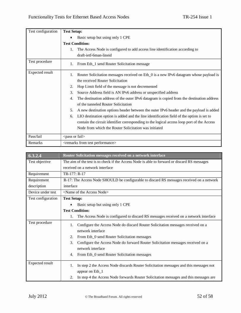
Functionality Tests for Ethernet Based Access Nodes TR-254 Issue 1
July 2012 © The Broadband Forum. All rights reserved 52 of 58
Test configuration Test Setup:
Basic setup but using only 1 CPE
Test Condition:
1. The Access Node is configured to add access line identification according to
draft-ietf-6man-lineid
Test procedure 1. From Eth_1 send Router Solicitation message
Expected result 1. Router Solicitation messages received on Eth_0 is a new IPv6 datagram whose payload is
the received Router Solicitation
2. Hop Limit field of the message is not decremented
3. Source Address field is AN IPv6 address or unspecified address
4. The destination address of the outer IPv6 datagram is copied from the destination address
of the tunneled Router Solicitation
5. A new destination options header between the outer IPv6 header and the payload is added
6. LIO destination option is added and the line identification field of the option is set to
contain the circuit identifier corresponding to the logical access loop port of the Access
Node from which the Router Solicitation was initiated
Pass/fail <pass or fail>
Remarks <remarks from test performance>
6.3.2.4 Router Solicitation messages received on a network interface
Test objective The aim of the test is to check if the Access Node is able to forward or discard RS messages
received on a network interface
Requirement TR-177: R-17
Requirement
description
R-17: The Access Node SHOULD be configurable to discard RS messages received on a network
interface
Device under test <Name of the Access Node>
Test configuration Test Setup:
Basic setup but using only 1 CPE
Test Condition:
1. The Access Node is configured to discard RS messages received on a network interface
Test procedure 1. Configure the Access Node do discard Router Solicitation messages received on a
network interface
2. From Eth_0 send Router Solicitation messages
3. Configure the Access Node do forward Router Solicitation messages received on a
network interface
4. From Eth_0 send Router Solicitation messages
Expected result 1. In step 2 the Access Node discards Router Solicitation messages and this messages not
appear on Eth_1
2. In step 4 the Access Node forwards Router Solicitation messages and this messages are

Functionality Tests for Ethernet Based Access Nodes TR-254 Issue 1
July 2012 © The Broadband Forum. All rights reserved 53 of 58
received on Eth_1
Pass/fail <pass or fail>
Remarks <remarks from test performance>
6.3.2.5 Router Advertisement messages originated by a host or RG
Test objective The aim of the test is to check if the Access Node is able to forward or discard Router
Advertisement messages originated by a host or RG
Requirement TR-177: R-18
Requirement
description
R-18: The Access Node SHOULD be configurable to block upstream Router Advertisement
messages originated by a host or RG
Device under test <Name of the Access Node>
Test configuration Test Setup:
Basic setup
Test Condition:
1. The Access Node is configured to forward upstream Router Advertisement messages
from CPE_1 and to block these messages from CPE_2
Test procedure 1. From Eth_1 send Router Advertisement messages
2. From Eth_2 send Router Advertisement messages
Expected result 1. In step 1 all messages are forwarded by the Access Node and received on Eth_0
2. In step 2 all messages are discarded by the Access Node and not appear on Eth_0
Pass/fail <pass or fail>
Remarks <remarks from test performance>
6.3.2.6 Redirect messages originated by a host or RG
Test objective The aim of the test is to check if the Access Node is able to forward or discard Redirect messages
originated by a host or RG
Requirement TR-177: R-19
Requirement
description
R-19: The Access Node MUST be configurable to discard upstream Redirect messages originated
by a host or RG
Device under test <Name of the Access Node>
Test configuration Test Setup:
Basic setup
Test Condition:
1. The Access Node is configured to forward upstream Redirect messages from CPE_1 and
to block these messages from CPE_2
Test procedure 1. From Eth_1 send Redirect messages
2. From Eth_2 send Redirect messages
Expected result 1. In step 1 all messages are forwarded by the Access Node and received on Eth_0

Functionality Tests for Ethernet Based Access Nodes TR-254 Issue 1
July 2012 © The Broadband Forum. All rights reserved 54 of 58
2. In step 2 all messages are discarded by the Access Node and not appear on Eth_0
Pass/fail <pass or fail>
Remarks <remarks from test performance>
6.3.2.7 Multicast Listener Query messages received on a user interface
Test objective The aim of the test is to check if the Access Node is able to forward or discard Multicast Listener
Query messages received on a user interface
Requirement TR-177: R-20
Requirement
description
R-20: The Access Node MUST be configurable to discard Multicast Listener Query messages
received on a user interface
Device under test <Name of the Access Node>
Test configuration Test Setup:
Basic setup
Test Condition:
1. The Access Node is configured to forward upstream Multicast Listener Query messages
from CPE_1 and to block these messages from CPE_2
Test procedure 1. From Eth_1 send Multicast Listener Query messages
2. From Eth_2 send Multicast Listener Query messages
Expected result 1. In step 1 all messages are forwarded by the Access Node and received on Eth_0
2. In step 2 all messages are discarded by the Access Node and not appear on Eth_0
Pass/fail <pass or fail>
Remarks <remarks from test performance>
6.3.3 IPv6 Spoofing Prevention
6.3.3.1 Populating IP Anti-spoofing table
Test objective The aim of the test is to check functionality of inspecting upstream and downstream DHCPv6
messages and RA messages and populating its IP Anti-spoofing Table accordingly
Requirement TR-177: R-21
Requirement
description
R-21 The Access Node SHOULD inspect upstream and downstream DHCPv6 messages (RFC
3315 [14], RFC 3633 [15]) and RA messages (RFC 4861 [12], RFC 4862 [13]) per user port and
populate its IP Anti-spoofing Table accordingly, in order to prevent host IP address spoofing and
delegated IP prefix spoofing
Device under test <Name of the Access Node>
Test configuration Test Setup:
Basic setup
Test Condition:
1. IP Anti-spoofing is enabled on the Access Node
Test procedure 1. IPv6 address of Eth_1 and Eth_2 should not exist in IP Anti-spoofing Table

Functionality Tests for Ethernet Based Access Nodes TR-254 Issue 1
July 2012 © The Broadband Forum. All rights reserved 55 of 58
2. Establish DHCPv6 transaction from Eth_1
3. Run Neighbor Discovery from Eth_2 (RS,RA)
Expected result 1. In step 2 DHCPv6 transaction is successful and IP Anti-spoofing Table is filled with
Eth_1 IPv6 address
2. In step 3 Eth_2 determine its IPv6 address and IP Anti-spoofing Table is filled with Eth_2
IPv6 address
Pass/fail <pass or fail>
Remarks <remarks from test performance>
6.3.3.2 Preventing IP address spoofing and delegated IP prefix spoofing
Test objective The aim of the test is to check functionality to prevent host IP address spoofing and delegated IP
prefix spoofing
Requirement TR-177: R-22
Requirement
description
R-22: Using the information obtained from R-21, the Access Node SHOULD provide a
mechanism to prevent host IP address spoofing and delegated IP prefix spoofing
Device under test <Name of the Access Node>
Test configuration Test Setup:
Basic setup
Test Conditions:
1. The Access Node is configured with IP Anti-spoofing mechanism
2. CPE_1 and CPE_2 are configured in VLAN_X
Test procedure 1. Establish DHCPv6 transaction from Eth_1
2. From Eth_2 send IPv6 traffic with source IPv6 address of Eth_1
3. Establish DHCPv6 transaction from Eth_2
4. From Eth_2 send IPv6 traffic with source IPv6 address of Eth_2
5. From Eth_2 send IPv6 traffic with source IPv6 address of Eth_1
Expected result 1. In step 1 DHCPv6 transaction is successful
2. In step 2 no traffic is received on Eth_0
3. In step 3 DHCPv6 transaction is successful
4. In step 4 IPv6 traffic is received on Eth_0
5. In step 2 no traffic is received on Eth_0
Pass/fail <pass or fail>
Remarks <remarks from test performance>
6.3.3.3 Updating IP Anti-spoofing Table entries
Test objective The aim of the test is to check that entries in the IP Anti-spoofing Table are updated according to
lifetime information received from the Router Advertisement and DHCPv6 messages
Requirement TR-177: R-23
Requirement R-23: The IP Anti-spoofing Table aging timers MUST be updated according to the lifetime

Functionality Tests for Ethernet Based Access Nodes TR-254 Issue 1
July 2012 © The Broadband Forum. All rights reserved 56 of 58
description information received from the Router Advertisement messages and DHCPv6 messages
Device under test <Name of the Access Node>
Test configuration Test Setup:
Basic setup
Test Condition:
1. DHCPv6 server and Eth_0 are configured with lifetime/aging time equal X (X random
value)
Test procedure 1. Establish DHCPv6 transaction from Eth_1
2. From Eth_1 send a Renew messages to request an extension of the lifetimes assigned
3. Server send a Replay messages to the client with new lifetimes
4. Run Neighbor Discovery from Eth_2 (RS,RA)
5. Wait until Eth_0 sends Router Advertisement update to Eth_2
Expected result 1. In step 1 DHCPv6 transaction is successful (Eth_1 gets IPv6 address)
2. After step 1 IP Anti-spoofing Table aging time for Eth_1 is equal to the one configured
on DHCPv6 server
3. After step 3 IP Anti-spoofing Table is updated with new lifetimes for Eth_1
4. In step 4 Neighbor Discovery is successful (Eth_2 gets IPv6 address)
5. In step 4 IP Anti-spoofing Table aging time for Eth_2 is equal to the one configured on
IPv6 router
6. After step 5 IP Anti-spoofing Table is updated for Eth_2
Pass/fail <pass or fail>
Remarks <remarks from test performance>
6.3.3.4 IP Anti-spoofing Table entries deleting after aging time
Test objective The aim of the test is to check if dynamic entries in the IP Anti-spoofing Table are deleted after
aging time
Requirement TR-177: R-24
Requirement
description
R-24: Dynamic entries in the IP Anti-spoofing Table MUST be aged out after the aging time
Device under test <Name of the Access Node>
Test configuration Test Setup:
Basic setup
Test Condition:
1. DHCPv6 server and Eth_0 are configured with lifetime/aging time equal X (X random
value)
Test procedure 1. Establish DHCPv6 transaction from Eth_1
2. Wait for aging time X
3. Run Neighbor Discovery from Eth_2 (RS,RA)
4. Wait for aging time X

Functionality Tests for Ethernet Based Access Nodes TR-254 Issue 1
July 2012 © The Broadband Forum. All rights reserved 57 of 58
Expected result 1. In step 1 DHCPv6 transaction is successful (Eth_1 gets IPv6 address)
2. After step 1 IP Anti-spoofing Table is filled with Eth_1 entry
3. After step 2 There is no Eth_1 entry in IP Anti-spoofing Table
4. In step 3 Neighbor Discovery is successful (Eth_2 gets IPv6 address)
5. After step 3 IP Anti-spoofing Table is filled with Eth_1 entry
6. After step 4 There is no Eth_2 entry in IP Anti-spoofing Table
Pass/fail <pass or fail>
Remarks <remarks from test performance>
6.3.4 Impact of IPv4 address exhaustion on IPv4 multicast
6.3.4.1 IGMP messages with 0.0.0.0 IPv4 source address
Test objective The aim of the test is to check if the Access Node is accepting and processing upstream
IGMPv2/v3 messages whose source address is 0.0.0.0
Requirement TR-177: R-58
Requirement
description
R-58: The Access Node MUST be able to accept and process upstream IGMPv2/v3 messages
whose source address is 0.0.0.0 (unspecified address), irrespective of any IP anti-spoofing rules.
This behavior MUST be configurable per access line
Device under test <Name of the Access Node>
Test configuration Test Setup:
Basic setup
Test Conditions:
1. IGMP processing for CPE_1 and CPE_2 is enabled on the Access Node
2. IP anti-spoofing is enabled for CPE_1 and CPE_2
3. The Access Node is configured to accept and process upstream IGMPv2/v3 messages
whose source address is 0.0.0.0 for CPE_1 and to discard this messages for CPE_2
Test procedure 1. From Eth_0 send multicast stream
2. From Eth_1 send IGMPv2/v3 join message with source address equal 0.0.0.0
3. From Eth_1 send IGMPv2/v3 leave message with source address equal 0.0.0.0
4. From Eth_2 send IGMPv2/v3 join message with source address equal 0.0.0.0
5. From Eth_2 send IGMPv2/v3 leave message with source address equal 0.0.0.0
Expected result 1. After step 1 No multicast stream is transmitted to Eth_1 and Eth_2
2. After step 2 Multicast stream is received on Eth_1
3. After step 3 No multicast stream is received on Eth_1
4. After step 4 No multicast stream is received on Eth_2
5. After step 4 and 5 No igmp messages are received on Eth_0
Pass/fail <pass or fail>
Remarks <remarks from test performance>

Functionality Tests for Ethernet Based Access Nodes TR-254 Issue 1
July 2012 © The Broadband Forum. All rights reserved 58 of 58
End of Broadband Forum Technical Report TR-254