fundamentals of object databases - ntuagtsat/collection/morgan claypool/fundamentals o… ·...
TRANSCRIPT
Fundamentals of Object DatabasesObject-Oriented and Object-Relational Design

Copyright © 2011 by Morgan & Claypool
All rights reserved. No part of this publication may be reproduced, stored in a retrieval system, or transmitted inany form or by any means—electronic, mechanical, photocopy, recording, or any other except for brief quotations inprinted reviews, without the prior permission of the publisher.
Fundamentals of Object Databases: Object-Oriented and Object-Relational Design
Suzanne W. Dietrich and Susan D. Urban
www.morganclaypool.com
ISBN: 9781608454761 paperbackISBN: 9781608454778 ebook
DOI 10.2200/S00315ED1V01Y201012DTM012
A Publication in the Morgan & Claypool Publishers seriesSYNTHESIS LECTURES ON DATA MANAGEMENT
Lecture #12Series Editor: M. Tamer Özsu, University of Waterloo
Series ISSNSynthesis Lectures on Data ManagementPrint 2153-5418 Electronic 2153-5426
Portions of this Work are based on the book An Advanced Course in Database Systems: BeyondRelational Databases, published by Pearson Education, Inc., © 2005.

Synthesis Lectures on DataManagement
EditorM. Tamer Özsu, University of Waterloo
Synthesis Lectures on Data Management is edited by Tamer Özsu of the University of Waterloo. Theseries will publish 50- to 125 page publications on topics pertaining to data management. The scopewill largely follow the purview of premier information and computer science conferences, such as ACMSIGMOD, VLDB, ICDE, PODS, ICDT, and ACM KDD. Potential topics include, but not arelimited to: query languages, database system architectures, transaction management, data warehousing,XML and databases, data stream systems, wide scale data distribution, multimedia data management,data mining, and related subjects.
Fundamentals of Object Databases: Object-Oriented and Object-Relational DesignSuzanne W. Dietrich and Susan D. Urban2010
Web Page Recommendation Models: Theory and AlgorithmsSule Gündüz-Ögüdücü2010
Multidimensional Databases and Data WarehousingChristian S. Jensen, Torben Bach Pedersen, and Christian Thomsen2010
Database ReplicationBettina Kemme, Ricardo Jimenez Peris, and Marta Patino-Martinez2010
Relational and XML Data ExchangeMarcelo Arenas, Pablo Barcelo, Leonid Libkin, and Filip Murlak2010
User-Centered Data ManagementTiziana Catarci, Alan Dix, Stephen Kimani, and Giuseppe Santucci2010

iv
Data Stream ManagementLukasz Golab and M. Tamer Özsu2010
Access Control in Data Management SystemsElena Ferrari2010
An Introduction to Duplicate DetectionFelix Naumann and Melanie Herschel2010
Privacy-Preserving Data Publishing: An OverviewRaymond Chi-Wing Wong and Ada Wai-Chee Fu2010
Keyword Search in DatabasesJeffrey Xu Yu, Lu Qin, and Lijun Chang2009

Fundamentals of Object DatabasesObject-Oriented and Object-Relational Design
Suzanne W. DietrichArizona State University
Susan D. UrbanTexas Tech University
SYNTHESIS LECTURES ON DATA MANAGEMENT #12
CM& cLaypoolMorgan publishers&

ABSTRACTObject-oriented databases were originally developed as an alternative to relational database tech-nology for the representation, storage, and access of non-traditional data forms that were increas-ingly found in advanced applications of database technology. After much debate regarding object-oriented versus relational database technology, object-oriented extensions were eventually incorpo-rated into relational technology to create object-relational databases. Both object-oriented databasesand object-relational databases, collectively known as object databases, provide inherent supportfor object features, such as object identity, classes, inheritance hierarchies, and associations betweenclasses using object references.
This monograph presents the fundamentals of object databases, with a specific focus on con-ceptual modeling of object database designs. After an introduction to the fundamental conceptsof object-oriented data, the monograph provides a review of object-oriented conceptual modelingtechniques using side-by-side Enhanced Entity Relationship diagrams and Unified Modeling Lan-guage conceptual class diagrams that feature class hierarchies with specialization constraints andobject associations. These object-oriented conceptual models provide the basis for introducing casestudies that illustrate the use of object features within the design of object-oriented and object-relational databases. For the object-oriented database perspective, the Object Data ManagementGroup data definition language provides a portable, language-independent specification of an objectschema, together with an SQL-like object query language. LINQ (Language INtegrated Query) ispresented as a case study of an object query language together with its use in the db4o open-sourceobject-oriented database. For the object-relational perspective, the object-relational features of theSQL standard are presented together with an accompanying case study of the object-relational fea-tures of Oracle. For completeness of coverage, an appendix provides a mapping of object-orientedconceptual designs to the relational model and its associated constraints.
KEYWORDSEER, LINQ, object databases, object-oriented databases, object-relational databases,UML

To my Jerry and JeremyWith Love
S. W. D.
In memory of my mother,Carolyn Christine Darling
To my husband, Joseph,for all of his love and support
S.D.U.

ix
Contents
Preface . . . . . . . . . . . . . . . . . . . . . . . . . . . . . . . . . . . . . . . . . . . . . . . . . . . . . . . . . . . . . . . . . xiii
Acknowledgments . . . . . . . . . . . . . . . . . . . . . . . . . . . . . . . . . . . . . . . . . . . . . . . . . . . . . . . . xv
List of Figures . . . . . . . . . . . . . . . . . . . . . . . . . . . . . . . . . . . . . . . . . . . . . . . . . . . . . . . . . xvii
List of Tables . . . . . . . . . . . . . . . . . . . . . . . . . . . . . . . . . . . . . . . . . . . . . . . . . . . . . . . . . . . xxi
1 Introduction to Object Databases . . . . . . . . . . . . . . . . . . . . . . . . . . . . . . . . . . . . . . . . . . .1
1.1 A Historical View of Object Databases . . . . . . . . . . . . . . . . . . . . . . . . . . . . . . . . . . . . 11.2 Fundamental Concepts . . . . . . . . . . . . . . . . . . . . . . . . . . . . . . . . . . . . . . . . . . . . . . . . . . 31.3 Object-Oriented Conceptual Modeling . . . . . . . . . . . . . . . . . . . . . . . . . . . . . . . . . . . . 5
1.3.1 Review of ER and UML Fundamentals . . . . . . . . . . . . . . . . . . . . . . . . . . . . . . 61.3.2 Class Hierarchies . . . . . . . . . . . . . . . . . . . . . . . . . . . . . . . . . . . . . . . . . . . . . . . . 151.3.3 Categories and XOR Association Constraint . . . . . . . . . . . . . . . . . . . . . . . . 231.3.4 Checkpoint: EER and UML . . . . . . . . . . . . . . . . . . . . . . . . . . . . . . . . . . . . . . 26
1.4 Bibliographic References . . . . . . . . . . . . . . . . . . . . . . . . . . . . . . . . . . . . . . . . . . . . . . . . 27
2 Object-Oriented Databases . . . . . . . . . . . . . . . . . . . . . . . . . . . . . . . . . . . . . . . . . . . . . . 31
2.1 The ODMG Standard . . . . . . . . . . . . . . . . . . . . . . . . . . . . . . . . . . . . . . . . . . . . . . . . . 312.2 The ODMG Object Definition Language . . . . . . . . . . . . . . . . . . . . . . . . . . . . . . . . . 322.3 Mapping Object-Oriented Conceptual Models to ODL . . . . . . . . . . . . . . . . . . . . 33
2.3.1 Classes, Attributes and Associations . . . . . . . . . . . . . . . . . . . . . . . . . . . . . . . . 332.3.2 Class Hierarchies . . . . . . . . . . . . . . . . . . . . . . . . . . . . . . . . . . . . . . . . . . . . . . . . 402.3.3 Categories . . . . . . . . . . . . . . . . . . . . . . . . . . . . . . . . . . . . . . . . . . . . . . . . . . . . . . 402.3.4 Checkpoint: Mapping to ODL . . . . . . . . . . . . . . . . . . . . . . . . . . . . . . . . . . . . 41
2.4 The ODMG Object Query Language . . . . . . . . . . . . . . . . . . . . . . . . . . . . . . . . . . . . 422.4.1 Path Expressions . . . . . . . . . . . . . . . . . . . . . . . . . . . . . . . . . . . . . . . . . . . . . . . . 462.4.2 OQL Expressions and Query Results . . . . . . . . . . . . . . . . . . . . . . . . . . . . . . . 462.4.3 Set Membership and Quantification . . . . . . . . . . . . . . . . . . . . . . . . . . . . . . . . 492.4.4 Ordering . . . . . . . . . . . . . . . . . . . . . . . . . . . . . . . . . . . . . . . . . . . . . . . . . . . . . . . 502.4.5 Using Collections . . . . . . . . . . . . . . . . . . . . . . . . . . . . . . . . . . . . . . . . . . . . . . . . 50

x
2.4.6 Aggregation and Grouping . . . . . . . . . . . . . . . . . . . . . . . . . . . . . . . . . . . . . . . 512.4.7 Checkpoint: OQL . . . . . . . . . . . . . . . . . . . . . . . . . . . . . . . . . . . . . . . . . . . . . . . 53
2.5 Case Study: LINQ and db4o . . . . . . . . . . . . . . . . . . . . . . . . . . . . . . . . . . . . . . . . . . . . 532.5.1 LINQ . . . . . . . . . . . . . . . . . . . . . . . . . . . . . . . . . . . . . . . . . . . . . . . . . . . . . . . . . 542.5.2 db4o . . . . . . . . . . . . . . . . . . . . . . . . . . . . . . . . . . . . . . . . . . . . . . . . . . . . . . . . . . . 61
2.6 Checkpoint . . . . . . . . . . . . . . . . . . . . . . . . . . . . . . . . . . . . . . . . . . . . . . . . . . . . . . . . . . . 642.7 Bibliographic References . . . . . . . . . . . . . . . . . . . . . . . . . . . . . . . . . . . . . . . . . . . . . . . . 64
3 Object-Relational Databases . . . . . . . . . . . . . . . . . . . . . . . . . . . . . . . . . . . . . . . . . . . . . 65
3.1 Built-In Constructed Types . . . . . . . . . . . . . . . . . . . . . . . . . . . . . . . . . . . . . . . . . . . . . 663.1.1 Row Types . . . . . . . . . . . . . . . . . . . . . . . . . . . . . . . . . . . . . . . . . . . . . . . . . . . . . 673.1.2 Arrays as Collections . . . . . . . . . . . . . . . . . . . . . . . . . . . . . . . . . . . . . . . . . . . . . 683.1.3 Checkpoint: Built-In Constructed Types . . . . . . . . . . . . . . . . . . . . . . . . . . . . 70
3.2 User-Defined Types . . . . . . . . . . . . . . . . . . . . . . . . . . . . . . . . . . . . . . . . . . . . . . . . . . . . 703.2.1 Distinct Types . . . . . . . . . . . . . . . . . . . . . . . . . . . . . . . . . . . . . . . . . . . . . . . . . . 703.2.2 Structured Types . . . . . . . . . . . . . . . . . . . . . . . . . . . . . . . . . . . . . . . . . . . . . . . . 723.2.3 Checkpoint: User-Defined Types . . . . . . . . . . . . . . . . . . . . . . . . . . . . . . . . . . 76
3.3 Typed Tables . . . . . . . . . . . . . . . . . . . . . . . . . . . . . . . . . . . . . . . . . . . . . . . . . . . . . . . . . . 763.4 Type and Table Hierarchies . . . . . . . . . . . . . . . . . . . . . . . . . . . . . . . . . . . . . . . . . . . . . 793.5 A Closer Look at Table Hierarchies . . . . . . . . . . . . . . . . . . . . . . . . . . . . . . . . . . . . . . 81
3.5.1 Inserting Rows in a Table Hierarchy . . . . . . . . . . . . . . . . . . . . . . . . . . . . . . . . 813.5.2 Querying a Table Hierarchy . . . . . . . . . . . . . . . . . . . . . . . . . . . . . . . . . . . . . . . 823.5.3 Deleting Rows from a Table Hierarchy . . . . . . . . . . . . . . . . . . . . . . . . . . . . . 833.5.4 Updating Rows in a Table Hierarchy . . . . . . . . . . . . . . . . . . . . . . . . . . . . . . . 833.5.5 Checkpoint: Typed Table Hierarchies . . . . . . . . . . . . . . . . . . . . . . . . . . . . . . . 84
3.6 Reference Types . . . . . . . . . . . . . . . . . . . . . . . . . . . . . . . . . . . . . . . . . . . . . . . . . . . . . . . 843.6.1 Scopes and Reference Checking . . . . . . . . . . . . . . . . . . . . . . . . . . . . . . . . . . . 863.6.2 Querying Reference Types . . . . . . . . . . . . . . . . . . . . . . . . . . . . . . . . . . . . . . . . 86
3.7 Mapping to the SQL Standard Object-Relational Features . . . . . . . . . . . . . . . . . . 873.7.1 Classes, Attributes, and Associations . . . . . . . . . . . . . . . . . . . . . . . . . . . . . . . 873.7.2 Checkpoint: Object-Relational Mapping of Classes, Attributes, and
Associations . . . . . . . . . . . . . . . . . . . . . . . . . . . . . . . . . . . . . . . . . . . . . . . . . . . . . 963.7.3 Class Hierarchies . . . . . . . . . . . . . . . . . . . . . . . . . . . . . . . . . . . . . . . . . . . . . . . . 983.7.4 Categories . . . . . . . . . . . . . . . . . . . . . . . . . . . . . . . . . . . . . . . . . . . . . . . . . . . . . . 99
3.8 Checkpoint . . . . . . . . . . . . . . . . . . . . . . . . . . . . . . . . . . . . . . . . . . . . . . . . . . . . . . . . . . 1003.9 Oracle: Object-Relational Database Mappings . . . . . . . . . . . . . . . . . . . . . . . . . . . . 100
3.9.1 Object Types and Type Hierarchies . . . . . . . . . . . . . . . . . . . . . . . . . . . . . . . 103

xi
3.9.2 Object Tables . . . . . . . . . . . . . . . . . . . . . . . . . . . . . . . . . . . . . . . . . . . . . . . . . . 1083.9.3 Reference Types . . . . . . . . . . . . . . . . . . . . . . . . . . . . . . . . . . . . . . . . . . . . . . . . 1093.9.4 Querying Substitutable Tables . . . . . . . . . . . . . . . . . . . . . . . . . . . . . . . . . . . . 1113.9.5 Varrays and Nested Tables as Collections . . . . . . . . . . . . . . . . . . . . . . . . . . . 112
3.10 Bibliographic References . . . . . . . . . . . . . . . . . . . . . . . . . . . . . . . . . . . . . . . . . . . . . . . 114
A Mapping Object-Oriented Conceptual Models to the Relational Data Model . 115
A.1 Notation and Terminology . . . . . . . . . . . . . . . . . . . . . . . . . . . . . . . . . . . . . . . . . . . . . 115A.2 Classes . . . . . . . . . . . . . . . . . . . . . . . . . . . . . . . . . . . . . . . . . . . . . . . . . . . . . . . . . . . . . . 116A.3 Associations . . . . . . . . . . . . . . . . . . . . . . . . . . . . . . . . . . . . . . . . . . . . . . . . . . . . . . . . . 117
A.3.1 Bidirectional Binary Associations . . . . . . . . . . . . . . . . . . . . . . . . . . . . . . . . . 117A.3.2 Participation and Multiplicity Constraints . . . . . . . . . . . . . . . . . . . . . . . . . . 119A.3.3 Recursive Associations . . . . . . . . . . . . . . . . . . . . . . . . . . . . . . . . . . . . . . . . . . 121A.3.4 N-ary Associations . . . . . . . . . . . . . . . . . . . . . . . . . . . . . . . . . . . . . . . . . . . . . 121A.3.5 Navigation of Unidirectional Associations . . . . . . . . . . . . . . . . . . . . . . . . . . 121A.3.6 Weak Entities and Identifying Relationships . . . . . . . . . . . . . . . . . . . . . . . 123A.3.7 Checkpoint: Classes and Associations . . . . . . . . . . . . . . . . . . . . . . . . . . . . . 124
A.4 Class Hierarchies . . . . . . . . . . . . . . . . . . . . . . . . . . . . . . . . . . . . . . . . . . . . . . . . . . . . . 124A.4.1 Creating a Table for Each Class . . . . . . . . . . . . . . . . . . . . . . . . . . . . . . . . . . 125A.4.2 Creating a Table for Subclasses Only . . . . . . . . . . . . . . . . . . . . . . . . . . . . . . 127A.4.3 Flattening the Hierarchy . . . . . . . . . . . . . . . . . . . . . . . . . . . . . . . . . . . . . . . . 129A.4.4 Specialization Constraints . . . . . . . . . . . . . . . . . . . . . . . . . . . . . . . . . . . . . . . 131A.4.5 Checkpoint: Class Hierarchies . . . . . . . . . . . . . . . . . . . . . . . . . . . . . . . . . . . . 133
A.5 Shared Subclasses . . . . . . . . . . . . . . . . . . . . . . . . . . . . . . . . . . . . . . . . . . . . . . . . . . . . . 133A.6 Categories . . . . . . . . . . . . . . . . . . . . . . . . . . . . . . . . . . . . . . . . . . . . . . . . . . . . . . . . . . . 136A.7 Checkpoint . . . . . . . . . . . . . . . . . . . . . . . . . . . . . . . . . . . . . . . . . . . . . . . . . . . . . . . . . . 138A.8 Bibliographic References . . . . . . . . . . . . . . . . . . . . . . . . . . . . . . . . . . . . . . . . . . . . . . . 138
Bibliography . . . . . . . . . . . . . . . . . . . . . . . . . . . . . . . . . . . . . . . . . . . . . . . . . . . . . . . . . . . 141
Authors’ Biographies . . . . . . . . . . . . . . . . . . . . . . . . . . . . . . . . . . . . . . . . . . . . . . . . . . . 145
Index . . . . . . . . . . . . . . . . . . . . . . . . . . . . . . . . . . . . . . . . . . . . . . . . . . . . . . . . . . . . . . . . . 147


PrefaceThis book covers the fundamentals of object databases from a design perspective. An object
database is a term used to refer collectively to object-oriented databases (OODBs) and object-relational databases (ORDBs). The reader is assumed to have familiarity with an object-orientedprogramming language and relational databases with SQL. After introducing the history and funda-mentals of object database features, side-by-side Enhanced Entity Relationship and UML diagramspresent various conceptual design issues for object-based applications, such as class hierarchies, spe-cialization constraints, and categories. The enterprises introduced in Chapter 1 are used throughoutthe book to illustrate the mapping of these object models to the ODMG OODB standard in Chap-ter 2, the object-relational features of the SQL standard in Chapter 3, and the relational model inthe Appendix.
Chapter 2 covers OODBs using the ODMG standard for describing and querying databaseobjects. After introducing ODL, the portable, language-independent data definition language fordescribing object-oriented schemas, Chapter 2 illustrates how to map the conceptual designs fromChapter 1 to ODL.The ODMG standard also includes an object query language,OQL, for queryingcollections of objects. This coverage provides the foundation for the discussion of the LanguageINtegrated Query (LINQ) language as a realization of an object query language available in practice.(LINQ can also query collections of tuples and collections of XML elements,although this expositiondiscusses LINQ’s capabilities for querying object collections.) The db4o open-source OODB is usedas a case study for illustrating the storage of objects with LINQ as a query language for retrievingobjects.
Chapter 3 covers ORDBs using the object-relational features of the SQL standard and acase study in Oracle. After presenting the use of constructed types from the SQL standard, suchas row types and arrays, the chapter focuses on the use of User-Defined Types (UDTs). A UDTprovides extensibility to the SQL pre-defined types, where the behavior of the type is definedthrough the use of methods. UDTs can be formed into type hierarchies that support inheritance ofattributes and methods. Object references can then be used to create relationships between objecttypes. Substitutable tables are defined to store the objects associated with a UDT and its subtypes.Techniques are also presented for mapping EER and UML schemas to the SQL object-relationaldata model and for maintaining the constraints of the conceptual design. The Oracle case studyelaborates on object extensions to the relational model, describing user-defined types, referencetypes, typed tables, and table hierarchies, as well as Oracle’s support for collections in the form ofvariable–sized arrays and nested tables.
The appendix covers the mapping of the object-oriented conceptual models to the relationaldata model and the intricacies of enforcing the object-based constraints within this environment.

xiv PREFACE
The various approaches for representing class hierarchies as tables are presented: table for each class,table for subclasses only, and a table to represent a flattened hierarchy. This coverage forms a basisfor understanding the orchestration that object relational mapping (ORM) tools provide in order toview data stored in relational tables as objects.
Suzanne W. Dietrich and Susan D. UrbanDecember 2010

AcknowledgmentsWe would like to thank, Tamer Özsu, the series editor, for his guidance. We also thank Diane
Cerra with Morgan Claypool and Dr. C. L. Tondo with T&T TechWorks, Inc. for their assistancewith the publishing of the book. We also want to acknowledge Mahesh Chaudhari for his feedbackon various parts of the book.
Parts of this book are based on material from An Advanced Course in Database Systems: BeyondRelational Databases published by Prentice Hall in 2005. We would like to acknowledge the manyorganizations and people who assisted on that project.
The development of an advanced database course for undergraduates was funded by theNational Science Foundation (DUE-9980417), and the book serves as one of the disseminationmechanisms for that work. We also appreciate the funding received from Microsoft Research andthe Arizona State University (ASU) Center for Research on Education in Science, Mathematics,Engineering, and Technology (CRESMET). As part of the NSF educational grant, we held twoindustry workshops to guide us in the development of the topics and course materials. We appre-ciate the input that we received from the following industry representatives and their companies:B. N. Rao, Honeywell; Lee Gowen, American Express; Leon Guzenda, Objectivity; Gary James,Homebid; Vishu Krishnamurthy, Oracle; John Nordlinger, Microsoft; Mark Rogers, CoCreate; JeffSmith, Honeywell; Amy Sundermier, Homebid; Roger Tomas, AG Communication Systems (nowLucent); Stephen Waters, Microsoft Research; Arleen Wiryo, Integrated Information Systems; andCindy Wu, Honeywell. We also held a faculty development workshop as part of the NSF dissem-ination process, and we would like to thank the workshop participants: Karen Davis, University ofCincinnati; Don Goelman, Villanova University; Lorena Gomez, Instituto Tecnologico y de Es-tudios Superiores de Monterrey; Mario Guimaraes, Kennesaw State University; Patricia Hartman,Alverno College; Héctor J. Hernández, Texas Tech University; Myrtle Jonas, The University of theDistrict of Columbia; Juan Lavariega, Instituto Tecnologico y de Estudios Superiores de Monterrey;Liz Leboffe, St. John Fisher College; Martha Myers, Kennesaw State University. We appreciate thedevelopment support that we received from various students at ASU: Shilpi Ahuja, Ingrid Biswas,Chakrapani Cherukuri, Marla Hart, Yonghyuk Kim, Ion Kyriakides, Shama Patel, Lakshmi Priya,Mathangi Ranganathan, Dan Suceava, Pablo Tapia, Ty Truong, Arleen Wiryo, Cindy Wu, YangXiao, Nilan Yang, and Mei Zheng. The students in the CSE 494 (Advanced Database Concepts)classes offered at ASU from spring 2000 through spring 2004 also deserve recognition for the valu-able input they provided on the content, course notes, and implementation examples that accompanythe book. We appreciate the thoughtful guidance provided by the reviewers: Sudarshan Chawathe,University of Maryland; Cindy Chen, University of Massachusetts-Lowell; Jeff Donahoo, BaylorUniversity; Don Goelman, Villanova University; William I. Grosky, Wayne State University; Le

xvi ACKNOWLEDGMENTS
Gruenwald, University of Oklahoma; Mario Guimaraes, Kennesaw State University; Patricia Hart-man, Alverno College; Héctor J. Hernández, Texas Tech University; Myrtle Jonas, University of theDistrict of Columbia; Jeff Naughton, University of Wisconsin; Joan Peckham, University of RhodeIsland; William Perrizo, North Dakota State University; Beth Plale, Indiana University; HassanReza, University of North Dakota; Shashi Shekhar, University of Minnesota; and Victor Vianu,University of California at San Diego.
Suzanne W. Dietrich and Susan D. UrbanDecember 2010

xvii
List of Figures
1.1 Abstract Enterprise in ER Notation with Cardinality Ratios . . . . . . . . . . . . . . . . . . 6
1.2 UML Class Diagram of the Abstract Enterprise . . . . . . . . . . . . . . . . . . . . . . . . 7
1.3 EER and UML Diagrams for Class A of the Abstract Enterprise . . . . . . . . . . 8
1.4 EER and UML Diagrams for Class C of the Abstract Enterprise . . . . . . . . . . 8
1.5 Abstract Enterprise in ER Notation with (Min, Max) Pairs . . . . . . . . . . . . . . 9
1.6 EER and UML Diagrams for M:N Association ab of the AbstractEnterprise . . . . . . . . . . . . . . . . . . . . . . . . . . . . . . . . . . . . . . . . . . . . . . . . . . . . . . . . . . 10
1.7 EER and UML Diagrams for 1:N Association ba of the AbstractEnterprise . . . . . . . . . . . . . . . . . . . . . . . . . . . . . . . . . . . . . . . . . . . . . . . . . . . . . . . . . . 10
1.8 EER and UML Diagrams for 1:1 Association bc of the AbstractEnterprise . . . . . . . . . . . . . . . . . . . . . . . . . . . . . . . . . . . . . . . . . . . . . . . . . . . . . . . . . . 11
1.9 EER and UML Diagrams for the Recursive Association bb of the AbstractEnterprise . . . . . . . . . . . . . . . . . . . . . . . . . . . . . . . . . . . . . . . . . . . . . . . . . . . . . . . . . . 12
1.10 EER and UML Diagrams for the Ternary Association finance . . . . . . . . . . . . . . . 13
1.11 Binary Approach to Modeling the finance Relationship . . . . . . . . . . . . . . . . . . . . . 13
1.12 A Revised UML Diagram for the Abstract Enterprise UsingUnidirectional Navigability . . . . . . . . . . . . . . . . . . . . . . . . . . . . . . . . . . . . . . . . . . . . . . 14
1.13 An ER Diagram for a Weak Entity and its Representation as a QualifiedAssociation in UML . . . . . . . . . . . . . . . . . . . . . . . . . . . . . . . . . . . . . . . . . . . . . . . . . . . 15
1.14 Generalization and Specialization in the Person Class Hierarchy. Based on“Database Models," by S. Urban in Encyclopedia of Electrical and ElectronicsEngineering, John G. Webster (editor); Copyright ©1999 John G. Webster.This material is used by permission of John Wiley & Sons, Inc. . . . . . . . . . . . . . . 17
1.15 Notation for Specialization in UML . . . . . . . . . . . . . . . . . . . . . . . . . . . . . . . . . . . . . . 18
1.16 EER Notation for Disjoint and Completeness Constraints . . . . . . . . . . . . . . . . . . . 19
1.17 Revised EER Person Hierarchy with Disjoint and Completeness Constraints.Based on “Database Models," by S. Urban in Encyclopedia of Electrical andElectronics Engineering, John G. Webster (editor); Copyright ©1999 John G.Webster. This material is used by permission of John Wiley & Sons, Inc. . . . . . . 20

xviii LIST OF FIGURES
1.18 UML Specialization Constraints on the Person Hierarchy . . . . . . . . . . . . . . . . . . . 21
1.19 The Project Attribute-Defined Specialization in an EER Diagram. Based on“Database Models," by S. Urban in Encyclopedia of Electrical and ElectronicsEngineering, John G. Webster (editor); Copyright ©1999 John G. Webster.This material is used by permission of John Wiley & Sons, Inc. . . . . . . . . . . . . . . 22
1.20 Use of a Discriminator for Project Specialization in a UML Diagram . . . . . . . . . 23
1.21 The StarModel Shared Subclass. Based on “Database Models," by S. Urban inEncyclopedia of Electrical and Electronics Engineering, John G. Webster (editor);Copyright ©1999 John G. Webster. This material is used by permission ofJohn Wiley & Sons, Inc. . . . . . . . . . . . . . . . . . . . . . . . . . . . . . . . . . . . . . . . . . . . . . . . . 24
1.22 EER Notation for Total and Partial Categories . . . . . . . . . . . . . . . . . . . . . . . . . . . . . 25
1.23 The Sponsor Partial Category. Based on “Database Models," by S. Urban inEncyclopedia of Electrical and Electronics Engineering, John G. Webster (editor);Copyright ©1999 John G. Webster. This material is used by permission ofJohn Wiley & Sons, Inc. . . . . . . . . . . . . . . . . . . . . . . . . . . . . . . . . . . . . . . . . . . . . . . . . 26
1.24 Using an Xor Constraint to Model the Partial Sponsor Category . . . . . . . . . . . . . 27
1.25 EER Diagram of the Hollywood Enterprise. Based on “DatabaseModels," by S. Urban in Encyclopedia of Electrical and Electronics Engineering,John G. Webster (editor); Copyright ©1999 John G. Webster. This materialis used by permission of John Wiley & Sons, Inc. . . . . . . . . . . . . . . . . . . . . . . . . . . . 28
1.26 UML Class Diagram of the Hollywood Enterprise . . . . . . . . . . . . . . . . . . . . . 29
2.1 ODL Syntax Summary . . . . . . . . . . . . . . . . . . . . . . . . . . . . . . . . . . . . . . . . . . . . . . . . . 33
2.2 Reified M:N Association for the Abstract Enterprise . . . . . . . . . . . . . . . . . . . 36
2.3 ODL Schema for the Hollywood Enterprise (Continues.) . . . . . . . . . . . . . . . . . . . . 43
2.3 (Continued.) ODL Schema for the Hollywood Enterprise . . . . . . . . . . . . . . . . . . . 44
2.4 UML Diagram for the ODL Specification of the Hollywood Enterprise . . 45
3.1 UML Diagram of the School Database. From Succeeding with ObjectDatabases by Akmal B. Chaudri and Roberto Zicari. Copyright ©2000 byAkmal B. Chaudri and Roberto Zicari. All rights reserved. Reproduced hereby permission of Wiley Publishing, Inc. . . . . . . . . . . . . . . . . . . . . . . . . . . . . . . . . . . . 67
3.2 SQL Syntax for Creating User-Defined Types . . . . . . . . . . . . . . . . . . . . . . . . . . . . . 71
3.3 SQL Syntax for Creating Typed Tables . . . . . . . . . . . . . . . . . . . . . . . . . . . . . . . . . . . 78
3.4 Rows in the Person Table Hierarchy . . . . . . . . . . . . . . . . . . . . . . . . . . . . . . . . . . . . . . 82

LIST OF FIGURES xix
3.5 Syntax for Defining Reference Types . . . . . . . . . . . . . . . . . . . . . . . . . . . . . . . . . . . . . 85
3.6 The SQL Standard Object-Relational Schema of the UnidirectionalAbstract Enterprise (Continues.) . . . . . . . . . . . . . . . . . . . . . . . . . . . . . . . . . . . . . 97
3.6 (Continued.) The SQL Standard Object-Relational Schema of theUnidirectional Abstract Enterprise . . . . . . . . . . . . . . . . . . . . . . . . . . . . . . . . . . . 98
3.7 The SQL Standard Object-Relational Schema of the School DatabaseEnterprise. ©ACM, 2003. This is a minor revision of the work publishedin “Using UML Class Diagrams for a Comparative Analysis of Relational,Object-Oriented, and Object-Relational Database Mappings," by S. Urbanand S. Dietrich in Proceedings of the 34th ACM SIGCSE Technical Symposiumon Computer Science Education, (2003) http://doi.acm.org/10.1145/620000.611923 (Continues.) . . . . . . . . . . . . . . . . . . . . . . . . . . . . . . . . . . . . . . . . . . . 101
3.7 (Continued.) The SQL Standard Object-Relational Schema of the SchoolDatabase Enterprise. ©ACM, 2003. This is a minor revision of the workpublished in “Using UML Class Diagrams for a Comparative Analysis ofRelational, Object-Oriented, and Object-Relational Database Mappings," byS. Urban and S. Dietrich in Proceedings of the 34th ACM SIGCSE TechnicalSymposium on Computer Science Education, (2003) http://doi.acm.org/10.1145/620000.611923 . . . . . . . . . . . . . . . . . . . . . . . . . . . . . . . . . . . . . . . . . . . . . 102
3.8 UML for the Oracle Object-Relational Case Study of the SchoolDatabase Enterprise. ©ACM, 2003. This is a minor revision of the workpublished in “Using UML Class Diagrams for a Comparative Analysis ofRelational, Object-Oriented, and Object-Relational Database Mappings," byS. Urban and S. Dietrich in Proceedings of the 34th ACM SIGCSE TechnicalSymposium on Computer Science Education, (2003) http://doi.acm.org/10.1145/620000.611923 . . . . . . . . . . . . . . . . . . . . . . . . . . . . . . . . . . . . . . . . . . . . . 104
3.9 Oracle DDL for the School Database Enterprise of theObject-Relational Mapping (Continues.) . . . . . . . . . . . . . . . . . . . . . . . . . . . . . . . . . . 105
3.9 (Continued.) Oracle DDL for the School Database Enterprise of theObject-Relational Mapping. . . . . . . . . . . . . . . . . . . . . . . . . . . . . . . . . . . . . . . . . . . . . 106
A.1 EER and UML Diagrams Illustrating Minimum and Maximum Constraints . . 120
A.2 Relational Schema of Abstract Enterprise using UnidirectionalNavigability . . . . . . . . . . . . . . . . . . . . . . . . . . . . . . . . . . . . . . . . . . . . . . . . . . . . . . . . . . 125
A.3 Extensional Schema for Class Hierarchies of the Hollywood Enterprise . . 127
A.4 Intensional Schema for Class Hierarchies of the Hollywood Enterprise . . 128
A.5 EER and UML Diagrams for a Simple Class Hierarchy . . . . . . . . . . . . . . . . . . . . 134

xx LIST OF FIGURES
A.6 SQL Assertion Specification Template for Specialization Constraints . . . . . . . . 134

xxi
List of Tables
2.1 Summary of ODL Mapping Heuristics for Classes, Attributes, andAssociations. . . . . . . . . . . . . . . . . . . . . . . . . . . . . . . . . . . . . . . . . . . . . . . . . . . . . . . . . . . 39
2.2 Summary of LINQ Query Operators. . . . . . . . . . . . . . . . . . . . . . . . . . . . . . . . . . . . . 61
3.1 Rows in the department Typed Table. . . . . . . . . . . . . . . . . . . . . . . . . . . . . . . . . . . . . 79
3.2 Summary of Object Relational Mapping Heuristics for Classes, Attributes,and Associations. . . . . . . . . . . . . . . . . . . . . . . . . . . . . . . . . . . . . . . . . . . . . . . . . . . . . . . 96
A.1 Summary of Relational Mapping Heuristics for Classes and Associations. . . . . . 124
A.2 Summary of Support for Specialization Constraints for Mapping ClassHierarchies. . . . . . . . . . . . . . . . . . . . . . . . . . . . . . . . . . . . . . . . . . . . . . . . . . . . . . . . . . . 133
A.3 Summary of Relational Mapping Heuristics for Class Hierarchies. . . . . . . . . . . . 135


1
C H A P T E R 1
Introduction to ObjectDatabases
This monograph covers object databases (ODBs), which is a term that refers to databases with objectfeatures. Historically, object-oriented databases (OODBs) developed first as an approach to addpersistence seamlessly into object-oriented programming languages (OOPLs). In response to thedevelopment of OODBs, the relational database community developed object-relational databases(ORDBs), which extend the relational data model with support for many of the similar object-oriented concepts. ORDBs blur the distinction between object-oriented and relational databases.Thus, the term object databases refers to OODBs and ORDBs collectively.
This chapter first covers a historical view of object databases, providing a context in which tounderstand the motivation for ODBs.The fundamental concepts of object features are then reviewedbriefly, since it is assumed that the reader is familiar with an OOPL. The chapter concludes withcoverage of the conceptual modeling of ODBs to provide the basis for introducing case studiesthat illustrate the use of object features within the design of object-oriented and object-relationaldatabases. This design perspective emphasizes class hierarchies and the specialization constraintsthat need to be considered when modeling enterprises that are object-based. The constraints on theclass hierarchies are presented with side-by-side Enhanced Entity-Relationship (EER) diagramsused by the database community and the Unified Modeling Language (UML) conceptual classdiagrams used by software engineers. These conceptual models are used extensively in Chapters 2and 3 to illustrate the mapping of the conceptual design of the database to its implementation datamodel, such as OODBs in Chapter 2 and ORDBs in Chapter 3. For completeness, Appendix Aincludes the mapping of EER and UML diagrams to the relational data model.
1.1 A HISTORICAL VIEW OF OBJECT DATABASES
For many years, relational database systems (RDBs) were well-suited for a wide range of businessapplications that effectively represented the enterprise of interest using a collection of tables. Asinterest in the use of database technology began to spread, relational database systems were usedfor a variety of new applications. These new applications included areas such as engineering design,geographic information systems, and telecommunication systems. A common characteristic of thesenew applications involved the use of large amounts of complex data, which is challenging to representsince the value of relational attributes are typically restricted to be simple, atomic values.

2 1. INTRODUCTION TO OBJECT DATABASES
Although Appendix A illustrates how the enterprises represented by the EER and UMLobject-oriented conceptual data models can be mapped to the relational data model to representthe data and constraints of the underlying application, the discussion does not address whetherthe approaches to representing objects in a relational data model are efficient. The view of anobject in the relational model requires the computation of joins over the various tables that maydescribe the object’s properties, including the inherited ones. This join computation may requireaccessing multiple tables that may not be physically stored near each other on disk. In an OODB,the properties of an object are typically clustered together on disk so that when an object is retrieved,all of its properties are accessible in memory. Another efficiency concern for RDBs versus OODBsis based on the navigation of associations. In a RDB, associations are by value, requiring a joinon the value given by the association. In an OODB, associations are inherently represented byobject references, which are an integral component of the underlying database system. Therefore,the navigation through associations between objects may be more efficient in OODBs than thesimulated navigation using joins in RDBs. Therefore, forcing such complex data into the atomic-valued requirement of the relational model may result in inefficient queries with numerous joinconditions required to reconstruct complex objects.
Furthermore, these new applications often required the representation of non-traditional dataforms, such as spatial, multimedia, or voice data. The relational data model, which restricted columntypes to be atomic values such as strings, integers, real numbers, and Boolean types, did not providethe type of extensibility needed to fully capture the data semantics of these new application domains.OODBs were developed in response to a need for managing data that did not fit well in the traditionaltable-oriented view of the relational model.
The development of OODBs in the mid-1980’s was also influenced at the time by the growinginterest in OOPLs. OOPLs such as Simula and C++ had emerged on the programming languagescene, providing a new approach to software development that emphasized the use of objects, withencapsulation of object structure and behavior through the use of abstract data types. With similarinterests in modeling complex, persistent data as objects within the database community, the mergerof object-based persistent data with OOPLs provided the promise of a new database paradigmfor the efficient representation of large, complex data sets together with the extensibility offeredby the programming language capability of user-defined abstract data types. A major advantageof the object-based data/language merger of the OODB paradigm, however, was resolution of theimpedance mismatch problem, thus providing seamless integration of the database with the program-ming language. The impedance mismatch problem refers to the differences that have traditionallyexisted between the set-oriented, declarative database approach to relational data access and theone-record-at-a-time, imperative programming language approach to data access. These differentstyles of data access coupled with differences in data types between the relational database sys-tem and application programming language causes data translation and conversion problems fordata-intensive applications. OODBs do not suffer from the impedance mismatch problem becausethe computationally-complete programming language is the database language. Furthermore, the

1.2. FUNDAMENTAL CONCEPTS 3
database and programming language data types are aligned into a consistent view of objects as in-stances of abstract data types. The details of OODBs are discussed in Chapter 2, describing theObject Data Management Group standard and a case study of the LINQ (Language INtegratedQuery) object query language with the db4o open-source OODB.
In response to the development of OODBs, the relational database community developedORDBs, which extend the relational data model with support for many of the similar object-oriented concepts. Object-relational features were first introduced in the SQL:1999 version of thestandard.The details of ORDBs are discussed in Chapter 3, describing the object-relational featuresof the SQL standard along with a case study of object-relational features in Oracle.
1.2 FUNDAMENTAL CONCEPTSThe goal of an ODB is to provide support for the persistence of objects, while supporting the myriadof features expected of a database system. Some of these expected database features include: theefficient management of persistent data; transactions, concurrency and recovery control; and an adhoc query language. The challenge for an ODB is to provide these database features in the contextof the complexities introduced by object-orientation.
An object is an abstract concept, generally representing an entity of interest in the enterprise tobe modeled by a database application.An object has state and behavior.The state of an object describesthe internal structure of the object where the internal structure refers to descriptive properties of theobject. Viewing a person as an object, the state of the object might contain descriptive informationsuch as an identifier, a name, and an address. The behavior of an object is the set of methods that areused to create, access, and manipulate the object. A person object, for example, may have methodsto create the object, to modify the object state, and to delete the object. The object may also havemethods to relate the object to other objects, such as enrolling a person in a course or assigning aperson to the instructor of a course. A method has a signature that describes the name of the methodand the names and types of the method parameters. Objects having the same state and behavior aredescribed by a class. A class essentially defines the type of the object where each object is viewed asan instance of the class. A method is a specific implementation of a method signature.
Given this fundamental definition of an object, the following object-oriented concepts aretypically associated with an ODB:
• complex objects
• object identity
• encapsulation
• extensibility
• class hierarchies and inheritance
• overriding, overloading and late binding

4 1. INTRODUCTION TO OBJECT DATABASES
The ability to define complex objects from simpler ones is an important property of object-orientation.Complex objects are defined using constructors, such as a tuple constructor that combinessimple objects to create a high-level form of an object. Using an engineering design example, anairplane can be viewed as a higher level object that is constructed from lower level objects, such asthe airplane body, the wings, the tail, and the engine. Each of these objects can, in turn, be complexobjects that are constructed from other simple or complex objects. Other examples of constructorsinclude collection constructors that define sets,bags or lists.Sets are unordered collections of elementswithout duplication. Bags are unordered collections that may contain duplicate elements. Lists are asequenced or ordered collection of elements. A plane, for example, has two wing objects, which canbe represented as a set. If the seats inside of the plane are viewed as objects, then a list can be usedto represent the ordered sequence of seats. ODBs provide inherent support for the construction ofcomplex objects.
Objects also have object identity through an internally assigned object identifier (oid). Unlikekeys in the relational model, an oid is immutable, which means that once an object is created, theoid remains invariant during the lifetime of the object. In contrast, the state of the object is mutable,meaning that the values of the properties of an object can change. The database system uses the oidfor references between objects to construct complex objects. Values of properties within the state ofthe object are not used to uniquely identify the object in the database. Therefore, changing the valueof a property of an object does not change the object’s identity. This is in contrast to the relationaldata model, which uses the value of the attributes that form a candidate key of the table to uniquelyidentify a tuple in the table. If the value of the attributes that form a candidate key change in therelational data model, then every value-oriented reference to the tuple must be updated.
The term encapsulation refers to the ability to create a class as an abstract data type, whichhas an interface and an implementation. The interface defines the behavior of the abstract data typeat a conceptual level. The implementation defines how this abstract behavior is realized using theprogramming language.Using the concept of encapsulation, the implementation of a class can changewithout affecting the interface that the class provides to the rest of the application. Encapsulationtherefore supports an important software engineering concept of separating class specification fromclass implementation. ODBs support encapsulation through the specification of user-defined types.
The ability of an ODB to support encapsulation also contributes to its extensibility. Withextensibility, there is no distinction between the usage of system-defined types versus user-definedtypes. In other words, users can create new types that correspond to the semantics of the applicationand then use these new types in the same manner as system-defined types. Extensibility is anappealing feature to non-traditional database applications that require the use of types other thanthe base types provided by the database management system. RDBs originally provided a system-defined table as an unordered collection of tuples of simple types, where operations on tables aretheoretically captured by the relational algebra operators and pragmatically realized by SQL.OODBsprovide a flexible approach to extensibility through the use of user-defined types via the OOPL.

1.3. OBJECT-ORIENTED CONCEPTUAL MODELING 5
Since the development of OODBs, RDBs and ORDBs have also been extended with the capabilityto define new types.
Another capability of object-orientation is the power to express class hierarchies and the inher-itance of state and behavior. Later in this chapter, a review of the EER and UML object-orientedconceptual data models discusses the details of how these models support inheritance. Appendix Aillustrates how the object-oriented conceptual data models can be mapped to a relational schema us-ing tables, views and constraints to creatively capture the semantics of an object-oriented enterprise.ODBs, however, inherently support class hierarchies and inheritance as an integral component ofthe data definition language.
Overriding, overloading, and late binding are additional characteristics of object-orientation,which are provided by ODBs. When defining the behavior of class hierarchies, a default behaviorfor a method name can be specified at the superclass level and redefined with a specialized behaviorfor the subclass. This redefinition is known as overriding since the redefinition at the subclass leveloverrides the default behavior at the superclass level. The term overloading refers to a concept thatallows a single class or multiple classes to have methods with the same name. The methods aredistinguished by the number and types of the parameters. Overloading is used together with theconcept of late binding, which means that the translation of an operation name to its appropriatemethod implementation must be resolved at run-time based on the type of an object.
The next section covers two fundamental object-oriented conceptual data models that graph-ically describe the data to be stored in an object database. Both the established EER diagrams usedby the database community and the UML conceptual class diagrams used by software engineers pro-vide advanced semantic modeling features that address class inheritance and constraints on subclassmembership.
1.3 OBJECT-ORIENTED CONCEPTUAL MODELING
Conceptual modeling is the process of developing a semantic description of an enterprise that is tobe captured in the design of an application. The Entity Relationship (ER) model has been one ofthe most well-known techniques associated with conceptual database design. Introduced in 1976by Peter Chen, the ER model provides a database-independent approach to describing the entitiesinvolved in a database application, together with the relationships and constraints that exist betweensuch entities. The ER model has evolved into the EER model, which enhances the original ERmodel with advanced features for conceptual modeling of class hierarchies. Introduced in the 1990s,software engineering uses UML as a visual, object-oriented modeling language to document thestructural and dynamic aspects of a software system, including many types of diagrams that capturestatic and dynamic interactions that are inherent in software. From a database perspective, UMLclass diagrams capture the static structure of the classes and the associations between classes that aresimilar to entities and relationships in EER diagrams.This section first presents a brief review of thenotation for EER and UML class diagrams because dialects of these models exist throughout theliterature. Then the object features supported by the conceptual modeling diagrams, such as class

6 1. INTRODUCTION TO OBJECT DATABASES
hierarchies and specialization constraints, are described.The enterprises presented in this section areused in later chapters to illustrate how the object-based models are mapped to the implementationlevel.
1.3.1 REVIEW OF ER AND UML FUNDAMENTALSAn Abstract Enterprise that illustrates various features of the conceptual models is introduced tocompare the terminology between ER and UML diagrams. Figure 1.1 provides an ER diagram ofthe Abstract Enterprise, while Figure 1.2 gives a corresponding UML diagram. The features of theconceptual models with respect to classes and associations will be discussed in terms of side-by-sidediagrams that illustrate the similarity between the EER and UML features.
A B
C Weak
keyOfA keyOfB
keyOfC
attrOfA attrOfB
attrOfAB
dependsOn
1
N
M N
1
1
multiValuedAttr
attrOfWk
attrOfC
derivedAttr
child
parent
N
1
N 1
compositeOfA
attrA2attrA1 attrA3
bb
attrOfBAbc
ab
ba
partialKey
Figure 1.1: Abstract Enterprise in ER Notation with Cardinality Ratios
Figure 1.3 illustrates the class A that has simple attributes (keyOfA, attrOfA), a compositeattribute (compositeOfA) and a derived attribute (derivedAttr). In the ER model, each entity isdenoted as a rectangle, with the name of the entity, such as A, inside of the rectangle. The propertiesdescribing the class are enclosed in ovals and attached by a line to the entity that it describes.Attributes denoted by single ovals are single-valued attributes, indicating that only one value willbe stored for the attribute. An underlined attribute name indicates the single-value or compositeattribute that forms the candidate key of an entity, which uniquely identifies an entity instance in

1.3. OBJECT-ORIENTED CONCEPTUAL MODELING 7
BAattrOfBA
«persistent»
«persistent» «persistent»A B
keyOfAattrOfAcompositeOfA/ derivedAttr
keyOfBattrOfB
«persistent»C
keyOfCattrOfCmultiValuedAttr[*]
«persistent»Weak
attrOfWk
partialKey 0..1
1..10..1
1
0..1 bb
1..*0..*
0..*
parent
0..*child
bcdependsOn
attrOfAB
«persistent»AB
Model as a record with attrA1, attrA2 and attrA3
1..1
Figure 1.2: UML Class Diagram of the Abstract Enterprise
an entity set. A composite attribute has two or more single-valued attributes as subcomponents. Aderived attribute, which is indicated by a dashed oval, represents a value that is not stored in thedatabase but can be calculated by other stored values. In UML, a rectangle encloses the entire class.The first compartment gives the name of the class. The second component lists the names of theproperties of the class. The behavior of the class is typically provided in a third component, whichmay be omitted for abstraction purposes as in the diagrams provided in this chapter. The persistent
stereotype in guillemets (〈〈 〉〉) above the class name identifies the class as a persistent class. A derivedattribute in UML is annotated by a / preceding the attribute name. The dog-eared notes in UMLare used to indicate composite attributes. There is no explicit annotation in UML for identifyingcandidate keys. However, the dog-eared notes can be used to indicate keys, too.
The class C shown in Figure 1.4 has simple attributes (keyOfC, attrOfC) and a multivaluedattribute (multiValuedAttr). A multivalued attribute indicates that the entity can have more thanone value for the attribute, where each value is of the same type. In an ER diagram, a multivalued

8 1. INTRODUCTION TO OBJECT DATABASES
compositeOfA
attrA2attrA1 attrA3
A
keyOfA attrOfA
derivedAttr
«persistent»A
UMLEER
Model as a record with attrA1, attrA2 and attrA3
keyOfAattrOfAcompositeOfA/derivedAttr
Figure 1.3: EER and UML Diagrams for Class A of the Abstract Enterprise
UML
«persistent»C
keyOfCattrOfCmultivaluedAttr[*]
EER
C
keyOfC
multiValuedAttrattrOfC
Figure 1.4: EER and UML Diagrams for Class C of the Abstract Enterprise
attribute is indicated by a double oval. In a UML diagram, a multivalued attribute is indicated byan array type property.
Interactions between classes are called relationships in an ER diagram and associations in aUML diagram. A relationship is denoted as a diamond, with lines connecting the diamond to theentities involved in the relationship. The name of the relationship appears inside of the diamond. InFigure 1.1, entities B and C are related through the bc relationship, while A and B are related throughtwo separate relationships: the ab relationship and the ba relationship. The numbers indicated onthe edges linking the relationship to its associated entities indicate the number of times that eachentity potentially participates in the relationship. These numbers, typically indicated by 1 or N, arecalled cardinality ratios.The cardinality ratios define cardinality constraints on the number of entitiesthat can participate in a relationship. Cardinality constraints are typically used in conjunction withparticipation constraints, which are either partial or total. Partial participation, which is denoted asa single line between a rectangle and a diamond, defines optional participation in a relationship.

1.3. OBJECT-ORIENTED CONCEPTUAL MODELING 9
Total participation, which is denoted as a double line between a rectangle and a diamond, indicatesrequired participation in a relationship. In a UML diagram, an association is represented by a singleedge linking the classes. The structural constraints on the associations are indicated by multiplicities,which are indicated by the min..max number of times that the class participates in the association.
A similar notation for providing more specific semantics on the participation constraints isavailable on ER diagrams using (min, max) pairs. Figure 1.5 shows the Abstract Enterprise inER notation with (min, max) pairs. The pair labels the edge linking the entity to the relationship,indicating the min and max number of times that an entity instance participates in the relationship.The (min, max) pairs replace the use of cardinality ratios and participation constraints. A minimumvalue of at least one implies total or required participation in the relationship, whereas a minimumvalue of zero implies partial participation.This use is consistent with multiplicities in UML diagrams.One observation is that the placement of multiplicities in UML appears opposite from the placementof (min, max) pairs in the ER diagram because UML only uses an edge to represent an association.UML diagrams also provide for shorthand notations for some commonly occurring multiplicities.For example, 1 is the same as 1..1 and * is the same as 0..*.
(0,N)
(1,1)
(1,N) (0,N)
(1,1)
(0,1)
(0,1)
(0,N)
(1,1) (0,N)
A B
C Weak
partialKey
keyOfA keyOfB
keyOfC
attrOfA attrOfB
attrOfAB
dependsOn
multiValuedAttr
attrOfWk
attrOfC
derivedAttr
child
parent
compositeOfA
attrA2attrA1 attrA3
bb
attrOfBAbc
ab
ba
Figure 1.5: Abstract Enterprise in ER Notation with (Min, Max) Pairs
The Abstract enterprise illustrates relationships having many-to-many, one-to-many,and one-to-one cardinality ratios. The ab association shown in Figure 1.6 represents a many-to-many relationship between classes A and B, where A has total participation in the ab relationship. An

10 1. INTRODUCTION TO OBJECT DATABASES
A is related to at least one but potentially many B’s, as indicated by the 1..* multiplicity on the UMLdiagram, and a B is related to potentially many A’s, with a multiplicity of 0..*. The ba association ofFigure 1.7 is an example of a one-to-many relationship between classes B and A, where A has totalparticipation in the ba association. An A is related to exactly one B, with a 1..1 multiplicity, and aB is related to potentially many A’s. The bc association shown in Figure 1.8 illustrates a one-to-onerelationship between classes B and C, where B has total participation in the bc association. A B isrelated to exactly one C, as indicated by the 1..1 multiplicity, and a C is related to (at most) one B, asshown by the 0..1 multiplicity.
«persistent» «persistent»A B
keyOfAattrOfAcompositeOfA/ derivedAttr
keyOfBattrOfB
1..*0..*
attrOfAB
«persistent»AB
EER UML
A B
keyOfA keyOfBattrOfA attrOfB
attrOfAB
M N
derivedAttr
compositeOfA
attrA2attrA1 attrA3
abModel as a record with attrA1,attA2 and attrA3
Figure 1.6: EER and UML Diagrams for M:N Association ab of the Abstract Enterprise
«persistent» «persistent»A B
keyOfAattrOfAcompositeOfA/ derivedAttr
keyOfBattrOfB
«persistent»BA
attrOfBA
Model as a record with attrA1,attA2 and attrA3
0..* 1..1
EER UML
A B
keyOfA keyOfBattrOfA attrOfB
attrOfBA
N 1
derivedAttr
compositeOfA
attrA2attrA1 attrA3
ba
Figure 1.7: EER and UML Diagrams for 1:N Association ba of the Abstract Enterprise

1.3. OBJECT-ORIENTED CONCEPTUAL MODELING 11
«persistent»C
keyOfCattrOfCmultiValuedAttr[*]
0..1
1..1bc
EER UML
«persistent»B
keyOfBattrOfB
B
C
keyOfB
keyOfC
attrOfB
1
1
multiValuedAttr
attrOfC
bc
Figure 1.8: EER and UML Diagrams for 1:1 Association bc of the Abstract Enterprise
The ab and ba associations of Figures 1.6 and 1.7, respectively, illustrate descriptive attributeson the association itself. In an ER diagram, the attribute’s oval is linked to the relationship diamond.In a UML diagram, however, descriptive attributes are represented by an association class. A class rep-resenting the association is created with the attributes describing the association and this associationclass is then linked to the association with a dashed line.
The Abstract Enterprise also represents a recursive association, in which a class has anassociation with itself. As an example, Figure 1.9 illustrates the bb association that is a recursiverelationship on the class B. Each instance of B that participates in the relationship plays a specific rolein the relationship. Role names, such as parent and child can be added as notations to associations toclarify the semantics of the relationship in both the ER and UML conceptual models. The instanceof B as a parent is related to 0 or many (0..*) children, and an instance of B as a child is related to atmost one (0..1) parent.
The associations that have been examined up to this point have been binary associations,defining a relationship between two entities. A relationship can define an n-ary association betweenseveral entities. Figure 1.10 illustrates a ternary finance relationship between three entities: Car,Person, and Bank. This association may exist in a car dealership application where a person buys acar that is financed by a particular bank. In an ER diagram, the relationship is linked to the three

12 1. INTRODUCTION TO OBJECT DATABASES
«persistent»B
keyOfBattrOfB
0..1 bbparent
0..*child
B
keyOfB attrOfB
child
parent
N
1bb
EER UML
Figure 1.9: EER and UML Diagrams for the Recursive Association bb of the Abstract Enterprise
entities that it relates. In a UML class diagram, an n-ary association is modeled as a diamond withlines branching out to the classes involved in the association. If the association has attributes, as inthe loanAmount in this example, then an association class can be attached to the diamond with adashed line.
Determining cardinalities for a relationship that is not binary is more difficult than for a binaryrelationship. To determine the cardinality on the Car end of the relationship, consider how manytimes a specific (p, b) pair can be related to c, where c is an instance of Car, p is an instance of Person,and b is an instance of Bank. One (p, b) pair can be related to many c entities since a person canwork with a specific bank to finance the purchase of many cars. A (c, b) pair, however, can be relatedonly to one p entity, assuming that a car can only be sold and financed to one person. As a result, a1 is placed next to the Person entity. Likewise, the 1 on the Bank end of the relationship states thata (c, p) pair can only be related to one b entity, indicating that the sale of a car to a person can befinanced only by one bank. In general, the lines between an entity and a relationship in a nonbinaryrelationship can be labeled with a 1 to represent participation in one relationship instance or with aletter, such as M, N, or P, to represent participation in many relationship instances, creating manydifferent relationship combinations.
A nonbinary relationship can always be modeled by introducing an entity to denote therelationship. Then a binary relationship is created for each entity involved in the n-ary relationship,linking it to the new entity. In the finance n-ary association, Finance is modeled as an entity,while Car, Person, and Bank have binary relationships with Finance. Figure 1.11 provides a viewof this representation. This approach is also known as a reified association in UML and representsan alternative notation to the use of association classes. In a reified association, the association ismodeled as a class. The process of transforming an association into a class is called reification. Whenreification is applied, something that is not usually viewed as an object in the application, such as anassociation between two classes, is modeled as a class.

1.3. OBJECT-ORIENTED CONCEPTUAL MODELING 13
loanAmountFinance
«persistent»
inventoryId
Car
model
Bankfinance
PersonbankId
bName
pId pName
1n
loanAmountmake
pIdpName
Person«persistent»
inventoryIdmakemodel
Car«persistent»
*
1
Bank«persistent»
bankIdbName
EER UML
1 1
Figure 1.10: EER and UML Diagrams for the Ternary Association finance
loanAmountfld
Finance«persistent»
pIdpName
Person«persistent»
inventoryIdmakemodel
Car«persistent»
Bank«persistent»
bankIdbName
inventoryId
Car
model
BankcarBought
Person
bankId
bName
pId pName
1
1
m
make
financedByFinance
loanAmount
n
fId
boughtBy
1 1
11
*
1
*
EER UML
Figure 1.11: Binary Approach to Modeling the finance Relationship
The associations that have been presented so far are bidirectional associations. In a bidirectionalassociation, it is assumed that the corresponding implementation of the schema will allow the userto traverse the association in either direction. ER diagrams only support bidirectional relationships.However, there is a concept of navigability of associations in UML class diagrams, allowing thedesigner to restrict the association to be unidirectional. This means that the implementation ofthe association is stored only in one direction. Figure 1.12 illustrates navigability in the contextof the Abstract Enterprise where the 1:N ba association and the 1:1 bc association have

14 1. INTRODUCTION TO OBJECT DATABASES
been changed to be unidirectional. The ba association is unidirectional from A to B, and the bc
association is unidirectional from B to C. Since the navigability of associations provides semanticsfor the implementation of the model, their use will be more evident in later discussions involvingmapping of the object-oriented conceptual models to the various implementation data models.
BAattrOfBA
«persistent»
«persistent» «persistent»A B
keyOfAattrOfAcompositeOfA/ derivedAttr
keyOfBattrOfB
«persistent»C
keyOfCattrOfCmultiValuedAttr[*]
«persistent»Weak
attrOfWk
partialKey 0..1
1..10..1
1
0..1 bb
1..*0..*
0..*
parent
0..*child
bcdependsOn
attrOfAB
«persistent»AB
Model as a record with attrA1, attrA2 and attrA3
1..1
Figure 1.12: A Revised UML Diagram for the Abstract Enterprise Using Unidirectional Navi-gability
Figure 1.13 shows the weak entity, named Weak, that is denoted by a double-line rectanglein an ER diagram. The attributes of a weak entity do not uniquely identify an instance of a weakentity in the database. As a result, a weak entity participates in an identifying relationship withanother entity, referred to as the identifying owner of the weak entity. The identifying relationshipis denoted by a double diamond in the ER diagram, and the weak entity has total participationin the identifying relationship. A weak entity has a partial key, indicated by an attribute with adashed underline. Semantically, a partial key uniquely identifies the weak entity in the context of itsidentifying owner.To create a candidate key for the weak entity, the partial key is combined with the

1.3. OBJECT-ORIENTED CONCEPTUAL MODELING 15
primary key of its identifying owner. In Figure 1.13, Weak has total participation in the dependsOn
identifying relationship, indicating that A is its identifying owner. The candidate key of Weak is thecombination of keyOfA and partialKey.
In a UML diagram, there is no explicit notation for representing weak entities. However,Figure 1.13 uses a qualified association. The partial key is used as a qualifier or index indicating theone A to which the Weak class dependsOn. Given a class A and the partialKey value, there is at mostone related Weak instance.
EER UML
«persistent»A
keyOfAattrOfAcompositeOfA/ derivedAttr
«persistent»Weak
attrOfWk
partialKey
0..1
1dependsOn
Model as a record with attrA1, attrA2 and attrA3
A
Weak
keyOfA attrOfA
dependsOn
1
N
attrOfWk
derivedAttr
compositeOfA
attrA2attrA1 attrA3
partialKey
Figure 1.13: An ER Diagram for a Weak Entity and its Representation as a Qualified Association inUML
1.3.2 CLASS HIERARCHIESEER and UML diagrams provide inherent support for modeling of classes into a hierarchical formknown as a class hierarchy or ISA hierarchy. The classes can be formed into superclasses and subclasses,related through an ISA relationship. This ISA relationship is also known as specialization or gener-alization. Specialization emphasizes attributes and relationships of the subclasses that do not existat the superclass level. Generalization emphasizes the common attributes and relationships of thesubclasses to form a superclass.

16 1. INTRODUCTION TO OBJECT DATABASES
To illustrate class hierarchies, consider a Hollywood Enterprise that requires modelinginformation about the different types of people involved in the production and review of movie andmodeling projects. In particular, this application requires capturing information about movie stars,models, agents, and movie critics. All of these different types of people have common characteristics,such as names and addresses, that need to be stored in the database. At the same time, each persontype also has additional information that must be captured to describe the characteristics of theirspecific type of job. These different types of people involved with the Hollywood scene can beorganized into a class hierarchy that emphasizes their commonalities and their differences.
Figure 1.14 presents the basic notation of the EER model for forming a class hierarchy. Inthis example, Person is a superclass that forms the root class of the hierarchy. A root class is alsoreferred to as a base class. MovieProfessional and Celebrity are subclasses of Person, indicating thatmovie professionals and celebrities are specific types of people.This relationship is often expressed asMovieProfessional ISA Person and Celebrity ISA Person. A subclass is connected to its superclassusing a line with a subset arc representing the direction of the ISA relationship. Critic and Agent
are specific types of movie professionals, while MovieStar and Model are specific types of celebrities.The Celebrity class is therefore a subclass with respect to its generalization relationship to Person,but a superclass with respect to its specialization relationship to MovieStar and Model. A similarobservation can be made for the MovieProfessional entity with respect to its ISA relationships withPerson, Critic, and Agent.
The basic notation for the specification of a UML class hierarchy is shown in Figure 1.15.A subclass is always connected to a superclass by a line with an open arrowhead pointing to thesuperclass. Each superclass/subclass relationship can be drawn as a separate line as in Figure 1.15(a).As a notational convenience, several subclasses can be connected to one arrowhead, forming a treestructure as in Figure 1.15(b). There is no semantic difference between the two notations.
1.3.2.1 Constraints on SpecializationClass hierarchies can be enhanced with constraints that refine the semantics of ISA relationships. Inparticular, the EER model supports the specification of the disjoint constraint and the completenessconstraint. The disjoint constraint indicates whether an instance of a superclass is restricted to bean instance of only one of its subclasses. If a specialization is not disjoint, then the specializationis overlapping, allowing an instance of the superclass to be an instance of more than one of itssubclasses. The completeness constraint specifies whether an instance of a superclass is required tobe an instance of at least one of its subclasses, which is referred to as a total specialization. Otherwise,the specialization is a partial specialization. A total specialization is also referred to as a coveringconstraint. Disjoint and completeness constraints can be used together to form the semantics ofsubclass membership with respect to the superclass.
Figure 1.16 illustrates the notational conventions for disjoint and completeness constraints. Asshown in Figure 1.16(a), A has a disjoint specialization into its subclasses B and C, which is indicatedby the use of a circle enclosing the letter “d” within the ISA specification. As a result, taking the

1.3. OBJECT-ORIENTED CONCEPTUAL MODELING 17
pId
CelebrityMovieProfessional
birthDate
MovieStar Model
preferences
Critic Agent
popularity agentFee movieType
company
name phone gender address
Person
Gen
eral
izatio
n Specialization
Figure 1.14: Generalization and Specialization in the Person Class Hierarchy. Based on “DatabaseModels," by S. Urban in Encyclopedia of Electrical and Electronics Engineering, John G. Webster (editor);Copyright ©1999 John G. Webster. This material is used by permission of John Wiley & Sons, Inc.
intersection of the instances of B and C should yield the empty set, indicating that an instance of A
can either be an instance of B or an instance of C, but not an instance of both B and C. If subclassesare not disjoint, then they are overlapping, meaning that an entity can be an instance of multiplesubclasses. The notation for the specification of overlapping subclass membership is indicated inFigure 1.16(b), using a circle to enclose the letter “o”. Since D has an overlapping specialization intoits subclasses E and F, an entity can be an instance of E and F at the same time. The notation usedto introduce EER class hierarchies in Figure 1.14 is, by default, assumed to represent overlappingsubclass membership.
The notation for indicating the completeness constraint in the EER is consistent with ERmodeling notation for participation constraints. A total specialization indicates total participation

18 1. INTRODUCTION TO OBJECT DATABASES
CelebrityMovieProfessional
Person«persistent»
Person«persistent»
«persistent» «persistent»CelebrityMovieProfessional
«persistent» «persistent»
(a) Separate Subclass Lines (b) Tree-structured Subclass Lines
Figure 1.15: Notation for Specialization in UML
of the superclass in the specialization relationship, which is denoted by a double line connectingthe superclass to the specialization circle. In Figure 1.16(c), an entity cannot exist as an instanceof A without also being an instance of either B or C. This implies that at the time an instance ofA is created, the specific subclass or subclasses to which it belongs must also be specified. Partialspecialization indicates partial participation in the specialization relationship, which is denoted bya single line connecting the superclass to the specialization circle. In Figure 1.16(d), an instanceof D is not required to be an instance of E or F. By default, the single lines used in the notationalconvention of Figure 1.14 also indicate partial specialization. For Figures 1.16(c) and Figure 1.16(d),the circle can be filled with either a “d” or an “o” to indicate the disjoint or overlapping constraint,respectively, creating four possibilities for specialization constraints: total disjoint, partial disjoint,total overlapping, or partial overlapping.
Figure 1.17 presents a revised version of Figure 1.14, adding disjoint and completeness con-straints.As indicated in Figure 1.17, a Person is not required to be a MovieProfessional or a Celebrity.When an instance of Person does exist at the subclass level, the Person instance cannot be botha Celebrity and a MovieProfessional at the same time. Since Celebrity has a total participationconstraint with its subclasses, creating a Celebrity instance also requires the creation of a MovieS-
tar or Model instance. Furthermore, since MovieStar and Model are overlapping, a celebrity can bean instance of both subclasses. MovieProfessional also has total participation with its subclasses.Membership in the Critic and Agent classes, however, is disjoint.
The UML notation for specialization constraints are explicit constraint names that are en-closed in braces ({}) and attached to the specialization link between a subclass and a superclass. Thedisjoint constraint specifies that the intersection of a set of subclasses must be the empty set. In otherwords, an instance of the superclass can only be an instance of one of the subclasses. The overlap-
ping constraint indicates that an instance of the superclass can be an instance of multiple subclasses.When there is no explicit specialization constraint given in the UML diagram, as in Figure 1.15, thedefault constraint is disjoint subclass membership.The complete and incomplete constraints specifywhether all of the subclasses have been shown in the class hierarchy, where complete indicates that
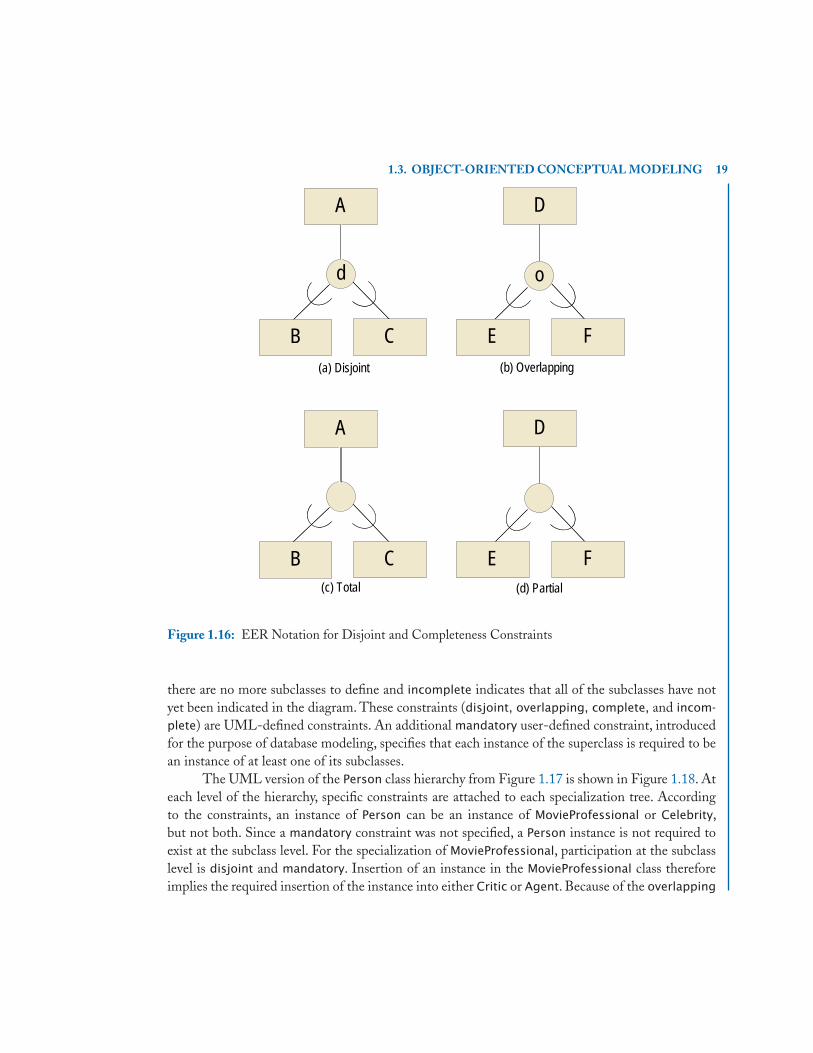
1.3. OBJECT-ORIENTED CONCEPTUAL MODELING 19
d
A
B C
o
E F
D
(a) Disjoint (b) Overlapping
(c) Total (d) Partial
A
B C E F
D
Figure 1.16: EER Notation for Disjoint and Completeness Constraints
there are no more subclasses to define and incomplete indicates that all of the subclasses have notyet been indicated in the diagram. These constraints (disjoint, overlapping, complete, and incom-
plete) are UML-defined constraints. An additional mandatory user-defined constraint, introducedfor the purpose of database modeling, specifies that each instance of the superclass is required to bean instance of at least one of its subclasses.
The UML version of the Person class hierarchy from Figure 1.17 is shown in Figure 1.18. Ateach level of the hierarchy, specific constraints are attached to each specialization tree. Accordingto the constraints, an instance of Person can be an instance of MovieProfessional or Celebrity,but not both. Since a mandatory constraint was not specified, a Person instance is not required toexist at the subclass level. For the specialization of MovieProfessional, participation at the subclasslevel is disjoint and mandatory. Insertion of an instance in the MovieProfessional class thereforeimplies the required insertion of the instance into either Critic or Agent. Because of the overlapping

20 1. INTRODUCTION TO OBJECT DATABASES
od
d
pId
CelebrityMovieProfessional
birthDate
MovieStar Model
preferences
Critic Agent
popularity agentFee movieType
company
name phone gender address
Person
Figure 1.17: Revised EER Person Hierarchy with Disjoint and Completeness Constraints. Based on“Database Models," by S. Urban in Encyclopedia of Electrical and Electronics Engineering, John G. Webster(editor); Copyright ©1999 John G. Webster. This material is used by permission of John Wiley & Sons,Inc.
and mandatory constraints on the Celebrity specialization, an instance of Celebrity is required toparticipate at the subclass level and can be a movie star and a model at the same time. Note that theoverlapping and disjoint constraints are identical to the corresponding constraints in the EER model.The mandatory constraint corresponds to the completeness constraint of the EER model, indicatingtotal specialization. The absence of the mandatory constraint corresponds to partial specialization.
1.3.2.2 Attribute-Defined SpecializationThe forms of specialization that have been examined so far are examples of user-defined specialization.In user-defined specialization, it is up to the application user to determine the subclass or subclassesto which a superclass instance can belong. Another form of specialization is attribute-defined special-ization, where the value of an attribute at the superclass level determines membership in a subclass.Figure 1.19 presents an example of attribute-defined specialization in the EER model. In this ex-

1.3. OBJECT-ORIENTED CONCEPTUAL MODELING 21
Person
MovieProfessional CelebritybirthDatecompany
MovieStarmovieType
Modelpreferences
AgentagentFee
Criticpopularity
{disjoint, mandatory} {overlapping, mandatory}
«persistent»
«persistent» «persistent» «persistent» «persistent»
«persistent»«persistent»
{disjoint}
pldname genderphoneaddress
Figure 1.18: UML Specialization Constraints on the Person Hierarchy
ample, the Project class is specialized into the FilmProject class and the ModelingProject class basedon the value of the type attribute of Project being either “F” or “M”.
As in the EER model, UML supports membership in subclasses based on the value of anattribute at the superlass level. The attribute that determines subclass membership is referred to asa discriminator. The use of a discriminator in UML always implies disjoint and mandatory subclassmembership. Furthermore, a subclass must exist for all possible values of the discriminator.
A discriminator is specified as a label on the specialization link and is considered to be apseudoattribute of the superclass. A pseudoattribute behaves like a regular class attribute except that

22 1. INTRODUCTION TO OBJECT DATABASES
Project
projectId
cost
location
type
d
description
ModelingProjectFilmProject
title
type = "F" type ="M"
Figure 1.19: The Project Attribute-Defined Specialization in an EER Diagram. Based on “DatabaseModels," by S. Urban in Encyclopedia of Electrical and Electronics Engineering, John G. Webster (editor);Copyright ©1999 John G. Webster. This material is used by permission of John Wiley & Sons, Inc.
the domain of the attribute is the set of subclass names. A pseudoattribute does not appear in theattribute compartment of a class definition.
Figure 1.20 illustrates the use of a discriminator to define the subclasses of Project. Thediscriminator is the type pseudoattribute. The possible values for type are “FilmProject" and “Mod-elingProject". Because a discriminator implies mandatory subclass membership, the Project class isan abstract class, illustrated with the name of the class in italics. An abstract class is a class that cannotbe directly instantiated. In Figure 1.20, a Project object can only be created either as an instanceof FilmProject or as an instance of ModelingProject. Because of the ISA constraint, the object isautomatically an instance of Project. At the Project level, the object has a type attribute that indicatesthe subclass to which the object belongs.
1.3.2.3 Multiple InheritanceEach example presented so far has illustrated the use of a specialization hierarchy, where each subclasshas only one superclass. In some modeling situations, it is possible for a subclass to have more thanone superclass, thus forming a specialization lattice. In a specialization lattice, a class with more thanone superclass is referred to as a shared subclass.
A shared subclass supports multiple inheritance, where the subclass inherits attributes fromall of its superclasses. A shared subclass must satisfy the multiple inheritance intersection constraint,

1.3. OBJECT-ORIENTED CONCEPTUAL MODELING 23
ModelingProjecttitle description
type
FilmProject«persistent» «persistent»
An Abstract class is denoted with the class name in italics or with {abstract} below the class name.
Project«persistent»
projectldlocationcost
Figure 1.20: Use of a Discriminator for Project Specialization in a UML Diagram
where the entity set of the subclass represents the intersection of the superclasses in the lattice. Inother words, an entity can only be an instance of a shared subclass if it is an instance of all of itssuperclasses.
In Figure 1.21, StarModel is a shared subclass with MovieStar and Model as superclasses. TheStarModel class therefore contains instances that are both movie stars and models. Each instanceof StarModel inherits attributes from MovieStar, Model, and Celebrity. One of the problems withmultiple inheritance is that each superclass can have attributes with the same name, thus creatingambiguity in the inheritance process. If the application designer decides to use multiple inheritance,the designer should ensure that the names of all inherited attributes are unique.
The superclasses of a shared subclass must have a common ancestor. The common ancestorensures that instances of the shared subclass are of the same fundamental type of entity. In theStarModel shared subclass, the Person class is a common ancestor, allowing the system to createonly one copy of the common attributes. A class that has multiple superclasses that do not havea common ancestor can be modeled using the category feature of the EER model or an XORassociation constraint in UML described in the next section.
1.3.3 CATEGORIES AND XOR ASSOCIATION CONSTRAINTWhereas multiple inheritance is used to model the intersection of two subclasses with a commonroot class, a category is used to model the union of two or more different types of classes. A categorytherefore represents a heterogeneous collection of entity instances, unlike other classes which are

24 1. INTRODUCTION TO OBJECT DATABASES
Celebrity
birthDate
o
MovieStar Model
preferencesmovieType
StarModel
CelebritybirthDate
{overlapping, mandatory}
movieTypeMovieStar
«persistent»Model
preferences
«persistent»
«persistent»
StarModel«persistent»
Figure 1.21: The StarModel Shared Subclass. Based on “Database Models," by S. Urban in Encyclopediaof Electrical and Electronics Engineering, John G. Webster (editor); Copyright ©1999 John G. Webster.This material is used by permission of John Wiley & Sons, Inc.
homogeneous collections. An instance of a category subclass must be an instance of at least one ofits superclasses but may not necessarily be a member of all of its superclasses.
Figure 1.22 illustrates the notational convention for categories together with the differenttypes of constraints on categorization. In general, the superclasses of a category are connected bya single line to a union symbol enclosed in a circle. The circle is then connected by a line to thecategory subclass. A union symbol on the line indicates the direction of the union relationship.
Categories must satisfy either the total category constraint or partial category constraint. A totalcategorization is depicted in Figure 1.22(a) with a double line between the subclass and the circle.If a category is constrained to be total, then every instance of each superclass must participate in thecategorization and be an instance of the category subclass. To satisfy the total category constraint, acategory must therefore be equal to the union of it superclasses. Partial categorization is shown inFigure 1.22(b) with a single line between the subclass and the circle. If a category is partial, thenan instance of a superclass is not required to participate in the categorization and need not be aninstance of the category subclass. To satisfy the partial category constraint, the category must be asubset of the union of its superclasses.
Figure 1.23 illustrates the use of categorization in the Hollywood Enterprise. In partic-ular, either a person or a company can sponsor a modeling project. Instead of creating two separatesponsor relationships between Person and ModelingProject and between Company and Modeling-

1.3. OBJECT-ORIENTED CONCEPTUAL MODELING 25
D E
F
B
C
(a) Total Category (b) Partial Category
A
Figure 1.22: EER Notation for Total and Partial Categories
Project, it is useful to define the notion of a sponsor as a category, where a Sponsor class is a subsetof the union of the Person and Company classes. A sponsoredBy relationship is then defined oncebetween the Sponsor class and the ModelingProject class. The Sponsor class is defined as a partialcategory to indicate that every person instance and every company instance is not required to bea sponsor. On the other hand, an instance of the Sponsor class represents an entity that is eithera Person instance or a Company instance, but not an instance of both the Person and Company
classes, as in the case of multiple inheritance and shared subclasses.Categories from the EER model can be represented using the xor constraint on associations in
UML class diagrams, which indicates that, at any given time, the application only needs to use oneof the associations. To illustrate this point, Figure 1.24 shows the Sponsor, Person, and Company
classes with two associations, one between Sponsor and Person and another between Sponsor andCompany. Sponsor is referred to as the base class. An xor constraint is specified between the twoassociations, drawn as a dashed line labeled with {xor}, indicating that a sponsor object can berelated to one person object or one company object, but not both. The multiplicity on the Person
and Company side of each association is 1, indicating that every instance of Sponsor is required tobe related to either a person or a company. In the opposite direction, the multiplicity specified can beused to indicate total or partial participation of Person and Company objects with Sponsor objects.In Figure 1.24, the multiplicity for each association is 0..1, indicating that each Person object andeach Company object does not have to be related to a Sponsor object, thus capturing the notion of apartial category from the EER model. The multiplicity can be changed to 1..1 on each associationto represent the concept of a total category, meaning that every person and every company is relatedto its corresponding Sponsor object.

26 1. INTRODUCTION TO OBJECT DATABASES
Company
cNamecId
Sponsor
description
ModelingProject
sponsoredBy
1
N
pId name phone gender address
Person
Figure 1.23: The Sponsor Partial Category. Based on “Database Models," by S. Urban in Encyclopediaof Electrical and Electronics Engineering, John G. Webster (editor); Copyright ©1999 John G. Webster.This material is used by permission of John Wiley & Sons, Inc.
1.3.4 CHECKPOINT: EER AND UMLThis section has presented the similar modeling capabilities of the EER and UML conceptualdata models using side-by-side illustrations, capturing classes, associations, class hierarchies withspecializations constraints, and categories. The complete conceptual design of the HollywoodEnterprise is presented in Figure 1.25 as an EER diagram and in Figure 1.26 as a UML classdiagram.
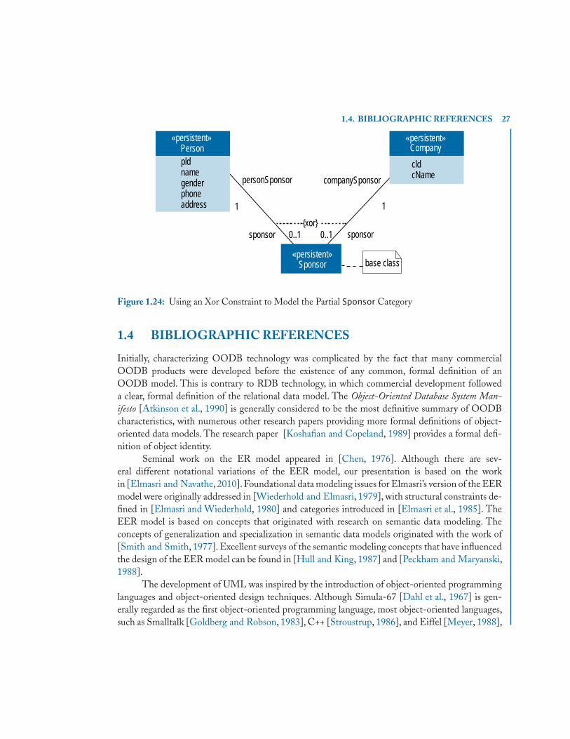
1.4. BIBLIOGRAPHIC REFERENCES 27
Person
Sponsor
«persistent»Company
«persistent»
«persistent»
{xor}
personSponsor companySponsor
sponsor sponsor
1
0..1
1
0..1
base class
pldnamegenderphoneaddress
cldcName
Figure 1.24: Using an Xor Constraint to Model the Partial Sponsor Category
1.4 BIBLIOGRAPHIC REFERENCES
Initially, characterizing OODB technology was complicated by the fact that many commercialOODB products were developed before the existence of any common, formal definition of anOODB model. This is contrary to RDB technology, in which commercial development followeda clear, formal definition of the relational data model. The Object-Oriented Database System Man-ifesto [Atkinson et al., 1990] is generally considered to be the most definitive summary of OODBcharacteristics, with numerous other research papers providing more formal definitions of object-oriented data models. The research paper [Koshafian and Copeland, 1989] provides a formal defi-nition of object identity.
Seminal work on the ER model appeared in [Chen, 1976]. Although there are sev-eral different notational variations of the EER model, our presentation is based on the workin [Elmasri and Navathe, 2010]. Foundational data modeling issues for Elmasri’s version of the EERmodel were originally addressed in [Wiederhold and Elmasri, 1979], with structural constraints de-fined in [Elmasri and Wiederhold, 1980] and categories introduced in [Elmasri et al., 1985]. TheEER model is based on concepts that originated with research on semantic data modeling. Theconcepts of generalization and specialization in semantic data models originated with the work of[Smith and Smith, 1977]. Excellent surveys of the semantic modeling concepts that have influencedthe design of the EER model can be found in [Hull and King, 1987] and [Peckham and Maryanski,1988].
The development of UML was inspired by the introduction of object-oriented programminglanguages and object-oriented design techniques. Although Simula-67 [Dahl et al., 1967] is gen-erally regarded as the first object-oriented programming language, most object-oriented languages,such as Smalltalk [Goldberg and Robson, 1983], C++ [Stroustrup, 1986], and Eiffel [Meyer, 1988],

28 1. INTRODUCTION TO OBJECT DATABASES
pId
CelebrityMovieProfessional
birthDateagentFor
o
MovieStar Model
Company
cnamecid
Sponsor
preferences
ProjectprojectId
cost
location
type
d description
ModelingProject
sponsoredBy
FilmProject
title
Critic Agent
popularity agentFeemovieType
modelsInactsIn paid
d
disMarriedTo
company
name phone gender
addresswife
husband
11
N
1
N
1
N
M M
N
type = "F" type ="M"
Person
Figure 1.25: EER Diagram of the Hollywood Enterprise. Based on “Database Models," by S.Urban in Encyclopedia of Electrical and Electronics Engineering, John G.Webster (editor);Copyright ©1999John G. Webster. This material is used by permission of John Wiley & Sons, Inc.
did not become popular until the early 1980’s. More recent definitions of object-oriented program-ming languages appear in the descriptions of C++ [Stroustrup, 2000] and Java [Arnold et al., 2005].Widespread interest in object-oriented programming languages was followed by research involvingthe development of object-oriented design techniques, the most prevalent of which were James Rum-baugh’s Object Management Technique [Rumbaugh et al., 1991], Ivar Jacobson’s Object-OrientedSoftware Engineering Notation [Jacobson et al., 1992], and Grady Booch’s Object-Oriented Anal-
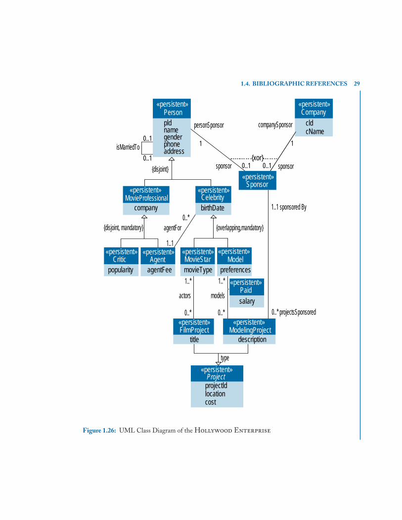
1.4. BIBLIOGRAPHIC REFERENCES 29
Person«persistent»
pldnamegenderphoneaddress
Company
0..1isMarriedTo
Sponsor
MovieProfessional
ModelingProject
CelebritybirthDatecompany
MovieStarmovieType
Modelpreferences
AgentagentFee
Criticpopularity
FilmProjecttitle description
Project
{disjoint, mandatory}0..*
1..1
agentFor {overlapping,mandatory}
1..1 sponsored By
0..* projectsSponsored
type
1..*
0..* 0..*
1..*
actors models
«persistent»
«persistent»
«persistent» «persistent» «persistent» «persistent»
«persistent»«persistent»
«persistent»
«persistent» «persistent»
Paidsalary
«persistent»
{disjoint}{xor}
personSponsor companySponsor
sponsor sponsor
1
0..1
1
0..10..1
cldcName
projectldlocation cost
Figure 1.26: UML Class Diagram of the Hollywood Enterprise

30 1. INTRODUCTION TO OBJECT DATABASES
ysis and Design Technique [Booch, 1994]. Eventually, the work of Rumbaugh, Jacobson, and Boochconverged when all three joined the Rational Software Corporation in the mid 1990’s, leadingto the creation of UML. In 1996, the specification of UML was submitted to the Object Man-agement Group (OMG) in response to a request for proposals for a standardized approach toobject-oriented modeling. UML was subsequently adopted as a standard by the OMG in 1997 andhas continued to evolve since that time. The specification of UML is maintained by OMG andcan be found at [OMG-UML, 2010]. Other useful sources of reference for UML class diagramsare [Rumbaugh et al., 2004], [Fowler, 2003], [Muller, 1999], and [Schmuller, 2004].
The Hollywood Enterprise used in this chapter originally appeared in an encyclopediaarticle on data modeling [Urban, 1999].
31
C H A P T E R 2
Object-Oriented DatabasesThe OODB community developed the Object Data Management Group (ODMG) standard asa means of establishing a common object interface specification to promote portability amongcommercial OODB products. The ODMG data model is based on the data model of the ObjectManagement Group (OMG) standard, which provides object-oriented interface capabilities forinteroperability across applications. The database designer uses the Object Definition Language(ODL) of the ODMG standard to specify the object types in the application according to theODMG object model, which is independent of a particular database or vendor. This chapter beginswith coverage of the ODMG object model and definition language, and then details the mappingof the EER and UML object-oriented conceptual data models to the ODL. Once the schemais defined in the ODL, the Object Query Language (OQL) of the ODMG standard provides adeclarative language for querying the database. OQL contributes a test bed for the study of queryoptimization techniques for object databases and a database independent way to describe declarativequeries over the ODMG object model. Today, the recently introduced Language INtegrated Query(LINQ) language provides a declarative query language for OODBs. The chapter concludes with acase study using the db4o open-source OODB with LINQ as the declarative query language.
2.1 THE ODMG STANDARD
Unlike the relational data model, which was introduced theoretically before the implementationof commercial relational database products, the object-oriented data model evolved by adding thecapability of persistence to objects in an object-oriented programming language. Several object-oriented database products emerged before the development of the ODMG Standard.The standardprovides a common ground to describe an object model, the specification of a schema over the objectmodel, and a query language. The standard also specifies language bindings for C++, Smalltalk, andJava. Language bindings are libraries of classes and functions that implement the concepts for thedefinition and manipulation of objects based on the standard in the given OOPL.
The modeling primitives of the ODMG standard are objects and literals. Objects have ob-ject identifiers. Literals, on the other hand, do not have object identifiers. Objects and literals arecharacterized by their types, which define their state and behavior. State refers to the values of theproperties, and behavior refers to the defined operations.
This chapter covers two languages that are part of the ODMG standard: ODL and OQL.ODL specifies a database schema over the object types allowed by the underlying object model.OQL is an ad hoc, declarative query language to retrieve data from an OODB. OQL is similar in

32 2. OBJECT-ORIENTED DATABASES
structure to SQL, the industry-standard query language for relational databases, having the familiarselect-from-where syntax. Queries are specified over a schema expressed in the ODL.
2.2 THE ODMG OBJECT DEFINITION LANGUAGE
ODL defines an object-oriented schema that is consistent with the underlying principles of theODMG object model. Figure 2.1 provides an ODL syntax summary for the definition of a class.The class className has an extent extentName and a key keyName. The declaration of an extentfor a class specifies that the database system automatically maintains a set of all instances of thatclass, which can be referenced by extentName. The keyName references the set of properties thatcan uniquely identify instances of the class. A composite key is specified by enclosing the list ofproperties that form the key in parentheses:
key (compositeKeypart1, compositeKeypart2)
Multiple candidate keys are separated in a list by commas:
keys key1, key2
A key declaration is optional, but a key can only be declared in the context of an extent declaration.The state of an object is defined by the value of its properties.The term property refers to either
an attribute or a relationship of a class. Both attributes and relationships have a name and a type.An attribute describes a characteristic of an object itself, whereas a relationship represents a binaryassociation between two classes. In Figure 2.1, className has an attribute attributeName of typeattributeType, and a relationship relationshipName of type relationshipType.The relationshipType
is either the type of the class given by the association or a collection of the associated type whenthe cardinality or multiplicity of the association is greater than one. In the ODMG object model, acollection can be a set, bag or list. Since the goal of an OODB system is to automatically maintainthe integrity of a relationship, the declaration of a relationship includes the inverse specificationfor the relationship. The inverseSpecification is a scoped name, giving the name of the role of theassociation as a relationship in the associated class.The behavior of the class is given by the signaturesof the methods defined on the class.
Since inheritance is an important feature provided by OODBs, the ODL provides inherentsupport for the specification of inheritance. There are two forms of inheritance supported by ODL:inheritance of both state and behavior, and the inheritance of behavior only. A class may inherit boththe state and behavior of another class as specified by the optional extends clause:
class subclass extends superclass( . . . ){
// properties and behavior specific to the subclass are defined here};

2.3. MAPPING OBJECT-ORIENTED CONCEPTUAL MODELS TO ODL 33
class className( extent extentName
key keyName ){ attribute attributeType attributeName;
relationship relationshipType relationshipNameinverse inverseSpecification;
// methodSignatures;};
Figure 2.1: ODL Syntax Summary
In this example, the subclass inherits both the state and behavior of the superclass, allowingfor the specification of additional properties and behavior for the subclass. The ODL also providessupport for the inheritance of behavior only. Since an interface describes the abstract behavior of atype, a type can inherit behavior only by using the ":" symbol, which is similar to the implementsclause in Java.
interface interfaceName{ // methodSignatures; };class className: interfaceName ( . . . ) { . . . };
Both forms of inheritance can be used in combination to achieve a form of multiple inheritance:
class subclassName extends superclassName: interfaceName ( . . . ) { . . . };
where subclassName inherits the state and behavior of superclassName and inherits the behaviorof interfaceName. Detailed examples of ODL are provided throughout the next section, whichillustrates how to map object-oriented conceptual models to the ODL.
2.3 MAPPING OBJECT-ORIENTED CONCEPTUAL MODELSTO ODL
Chapter 1 provided an overview of the fundamental object database concepts using the EER andUML object-oriented conceptual models.This section uses the side-by-side illustrations from Chap-ter 1 to map the similar concepts from the EER and UML diagrams into an object-oriented schemaexpressed in the ODL. The fundamental concepts of mapping classes, attributes and associationsare presented first in the context of the Abstract Enterprise. The mapping of class hierarchiesand categories are discussed using the Hollywood Enterprise as an example.
2.3.1 CLASSES, ATTRIBUTES AND ASSOCIATIONSRecall the class A of Figure 1.3 that has simple attributes (keyOfA, attrOfA), a composite attribute(compositeOfA) and a derived attribute (derivedAttr). In ODL, class A is mapped to a class having

34 2. OBJECT-ORIENTED DATABASES
an extent extentOfA, which uniquely identifies instances of the class using the key keyOfA. Thesimple attributes keyOfA and attrOfA are declared as type string, for simplicity. Since ODL providesinherent support for complex types, the composite attribute of A can be directly represented. A typeCompositeStruct consisting of the composite attributes (attrA1, attrA2, and attrA3) is first defined,and the attribute compositeOfA is declared to be of type CompositeStruct. The derived attribute isdefined using a get method. The signatures of the methods associated with the behavior of the classfor creating new instances, destroying instances and providing standard access are also part of theclass definition. For brevity, the method signatures are not included in the examples that follow.
struct CompositeStruct{ string attrA1;
string attrA2;string attrA3;
};class A( extent extentOfA,
key keyOfA ){ attribute string keyOfA;
attribute string attrOfA;attribute CompositeStruct compositeOfA;. . .
// provide get method signature for derivedAttr// method signatures for behavior
};
The class C of Figure 1.4 illustrates a multivalued attribute, named multiValuedAttr. In therelational data model, a multivalued attribute must be mapped to its own table including the keyattribute of the class. Since an object-oriented data model supports collections, multiValuedAttrcan be represented directly as an attribute of C having a collection as its type. Although the setcollection type is used in this example, the choice of the appropriate collection type (set, bag, or list)is ultimately based on the semantics of the enterprise.
class C ( . . . ){ . . .
attribute set<string> multiValuedAttr;};
Binary associations without attributes are mapped to a relationship in the ODL.A relationshipin ODL has a name,a type,and an inverse specification.As an example,consider the 1:1 bc associationbetween the classes B and C as illustrated in Figure 1.8. In class B, define a relationship named bTOc
of type C having as its inverse the relationship named cTOb in class C, which is specified as C::cTOb.In class C, the relationship cTOb is of type B with inverse B::bTOc.

2.3. MAPPING OBJECT-ORIENTED CONCEPTUAL MODELS TO ODL 35
class B (. . .){ . . .
relationship C bTOc inverse C::cTOb;};class C (. . .){ . . .
relationship B cTOb inverse B::bTOc;};
The specification of a relationship requires the definition of its inverse since the database isresponsible for maintaining the integrity of the relationship. For example, if the instance of the bTOc
relationship for an object bi is assigned the object cj , then the database system automatically updatesthe instance of the relationship cTOb of cj to the object bi .
The cardinality ratio constraints of the association are inherent in the specification of theobject-oriented schema by defining the type of the relationship and its inverse. For the bc associationin Figure 1.8, the type of each association is a single object of the appropriate class. One type ofconstraint that is not defined implicitly in the schema is the total participation of class B in the bc
association. This constraint is straightforward in the relational data model by using the not null
attribute constraint. In an object-oriented database, this constraint must be handled as part of thebehavior of the object. For example, the constructor method for class B must ensure that the valueof the bTOc relationship is not null.
The above example illustrated the mapping to ODL for a 1:1 association. A similar templateapplies to a binary association without attributes having 1:N or M:N cardinality ratios. The onlydifference is that the type of the many side of the association is a collection. The appropriate choicefor the type of the collection as set, bag or list depends on the semantics of the enterprise.
When binary associations have attributes, an association class must be introduced to representthe attributes of the association. The association class also includes two relationships - one for eachclass participating in the binary association.Consider the M:N ab association between classes A and B
that has a descriptive attribute attrOfAB, as shown in Figure 1.6. Figure 2.2 gives the UML diagramfor the corresponding reified association. An association class is defined as the class named AB,having the attribute attrOfAB and two relationships: abTOa and abTOb. The relationship abTOa isof type A, indicating the instance of class A that is participating in the relationship instance. Similarly,the relationship abTOb is of type B, indicating the instance of class B that is participating in therelationship instance.The definitions for the classes involved in the association include relationshipsto the new association class. Class A contains the relationship aTOab having as its type a set of AB
objects, since an object of type A is related to at least one and potentially many Bs through the AB
association class. Similarly, class B contains the relationship bTOab having as its type a set of AB
objects, since an object of type B is related to potentially many As through the AB association class.
class AB( extent extentOfAB )

36 2. OBJECT-ORIENTED DATABASES
{ attribute string attrOfAB;relationship A abTOa inverse A::aTOab;relationship B abTOb inverse B::bTOab;
};class A (. . .){ . . .
relationship set<AB> aTOab inverse AB::abTOa;};class B (. . .){ . . .
relationship set<AB> bTOab inverse AB::abTOb;};
«persistent» «persistent»A B
keyOfBattrOfB
1..* 0..*
«persistent»AB
attrOfAB1 1keyOfAattrOfAcompositeOfA/derivedAttr
abTOa aTOab bTOab abTObModel as a record with attrA1, attrA2 and attrA3
Figure 2.2: Reified M:N Association for the Abstract Enterprise
The mapping of recursive associations is similar to the mapping of nonrecursive associations,except that the recursive association is relating the same class to itself. In Figure 1.9, the class B has arecursive association bb. One straightforward approach to mapping a recursive association is to usethe role names of the association as the name of the relationships in ODL. For example, the parent
role of the bb association is of type B having the child role as its inverse relationship. The child roleis a collection type, representing the children of the parent. Again, by defining a relationship, thedatabase system is responsible for automatically maintaining the integrity of the relationship. Forexample, when the parent relationship instance is assigned a value, the database system automaticallyadds the associated object to the child relationship.
class B( extent extentOfB
key keyOfB ){ . . .
relationship B parent inverse B::child;relationship set<B> child inverse B::parent;
};
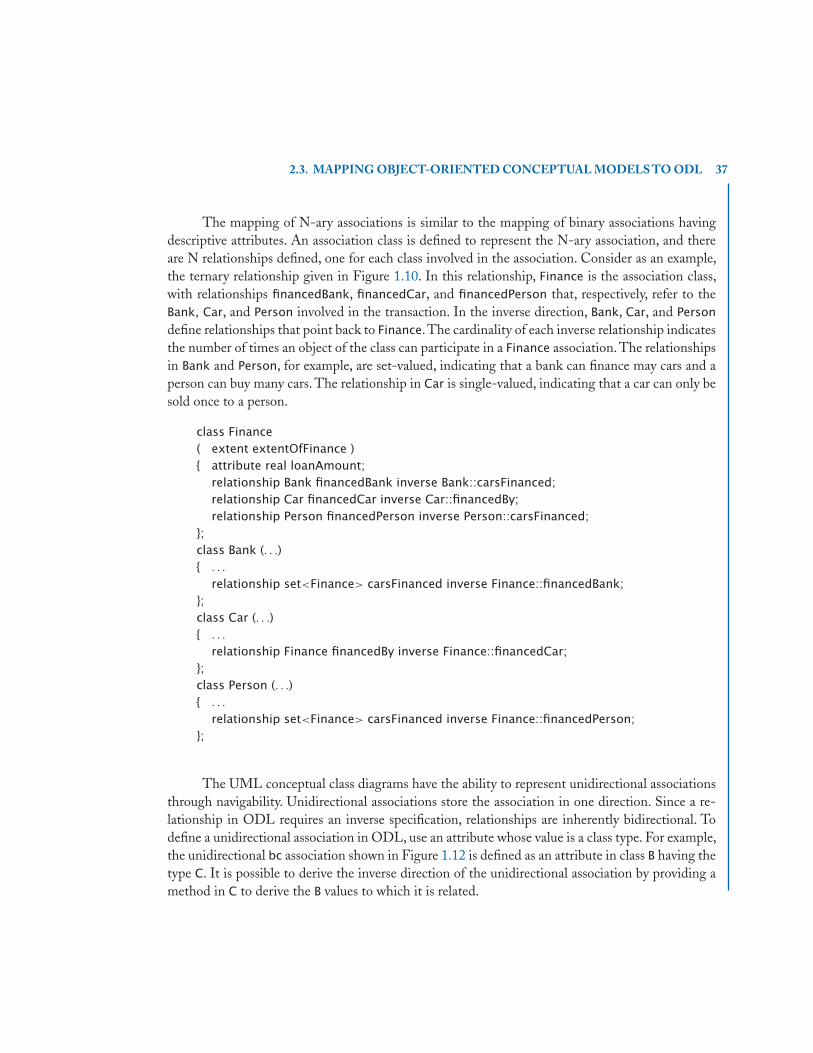
2.3. MAPPING OBJECT-ORIENTED CONCEPTUAL MODELS TO ODL 37
The mapping of N-ary associations is similar to the mapping of binary associations havingdescriptive attributes. An association class is defined to represent the N-ary association, and thereare N relationships defined, one for each class involved in the association. Consider as an example,the ternary relationship given in Figure 1.10. In this relationship, Finance is the association class,with relationships financedBank, financedCar, and financedPerson that, respectively, refer to theBank, Car, and Person involved in the transaction. In the inverse direction, Bank, Car, and Person
define relationships that point back to Finance.The cardinality of each inverse relationship indicatesthe number of times an object of the class can participate in a Finance association. The relationshipsin Bank and Person, for example, are set-valued, indicating that a bank can finance may cars and aperson can buy many cars. The relationship in Car is single-valued, indicating that a car can only besold once to a person.
class Finance( extent extentOfFinance ){ attribute real loanAmount;
relationship Bank financedBank inverse Bank::carsFinanced;relationship Car financedCar inverse Car::financedBy;relationship Person financedPerson inverse Person::carsFinanced;
};class Bank (. . .){ . . .
relationship set<Finance> carsFinanced inverse Finance::financedBank;};class Car (. . .){ . . .
relationship Finance financedBy inverse Finance::financedCar;};class Person (. . .){ . . .
relationship set<Finance> carsFinanced inverse Finance::financedPerson;};
The UML conceptual class diagrams have the ability to represent unidirectional associationsthrough navigability. Unidirectional associations store the association in one direction. Since a re-lationship in ODL requires an inverse specification, relationships are inherently bidirectional. Todefine a unidirectional association in ODL, use an attribute whose value is a class type. For example,the unidirectional bc association shown in Figure 1.12 is defined as an attribute in class B having thetype C. It is possible to derive the inverse direction of the unidirectional association by providing amethod in C to derive the B values to which it is related.

38 2. OBJECT-ORIENTED DATABASES
class B ( . . . ){ . . .
attribute C bc;};
A weak class in an EER diagram is typically related to its identifying owner by a 1:N rela-tionship. In Figure 1.13, the Weak class is related to its identifying owner class A by its identifyingrelationship dependsOn. The candidate key of a weak class is formed by the combination of theprimary key of its identifying owner and its own partial key, which uniquely identifies the weak objectin the context of the identifying owner. In the UML diagram of Figure 1.13, dependsOn representsa qualified association based on the partialKey. One way to map this type of an association is todefine a relationship that links the weak class to its identifying owner. For the semantics expressed inFigure 1.13, the relationship linkToWeak defined in class A represents the collection of Weak objectsassociated with an instance of class A. The inverse relationship defined as linkToOwner in the Weak
class links the Weak instance to its identifying owner instance, which is of type A having the attributekeyOfA as its candidate key. One may also choose to maintain the extent of the Weak class, whichrequires storing the value of the key of the identifying owner (keyOfA) to use in combination withthe partialKey.
class A( extent extentOfA
key keyOfA ){ attribute string keyOfA;
relationship set<Weak> linkToWeak inverse Weak::linkToOwner;. . .
};class Weak( extent extentOfWeak
key (keyOfA, partialKey) ){ attribute string partialKey;
attribute string keyOfA;relationship A linkToOwner inverse A::linkToWeak;. . .
};
2.3.1.1 Constraints on Classes, Attributes and AssociationsWhen mapping the object-oriented conceptual data models to an object-oriented data model, thereare a number of constraints that need to be captured at the implementation level. These constraintson classes, attributes, and associations include the specification of candidate keys, referential integrity,as well as participation and multiplicity constraints.
In ODL, there is a key clause to specify the uniqueness of candidate keys, and referentialintegrity is inherent in the specification of the type of a property. The type specification in ODL

2.3. MAPPING OBJECT-ORIENTED CONCEPTUAL MODELS TO ODL 39
also inherently supports a simple cardinality constraint. For example, the type of a property is a classtype when the property is related to one object of that type or a collection of a class type when theproperty is related to more than one object of that type.
For more complicated participation and multiplicity constraints, the constraints must be im-plemented as part of the behavior of the object. A total participation constraint requires that thebehavior for constructing an object and modifying the property verify that the value of the propertyis not null. This verification is written in the underlying OOPL for the OODB. Similarly, verifyingspecific multiplicity constraints (other than the simple one-to-one or one-to-many cardinality con-straints that are inherent in the specification of relationships) requires the constraint to be checkedin the behavior of the object.
2.3.1.2 Checkpoint: ODL Mapping of Classes, Attributes and AssociationsTable 2.1 summarizes the mapping of classes, attributes, and associations to ODL, using the namesC, C1 and C2 to represent generic classes. In the table, the first column indicates the componentbeing mapped to the object model. The second column provides the name of the class to which theODL definition is added. The third column indicates the required definition in ODL to realize thecomponent in the object model. As indicated in the table, ODL inherently supports the specificationof class, attributes, and associations. The specification of class hierarchies in ODL is described inthe next section.
Table 2.1: Summary of ODL Mapping Heuristics for Classes, Attributes, andAssociations.
Component Class ODL Definitionclass C C class C ( extent extentOfC )
single-valued or composite C attribute typeOfS s;
attribute s of C
multivalued attribute C attribute set < typeOfElementlnM > m;
m of C
binary association – C1 relationship C2 c1TOc2 inverse C2::c2TOc1;
no attributes (1:1 shown) C2 relationship C1 c2TOc1 inverse C1::c1TOc2;
binary association ac C1 relationship set < AC > c1TOac
with attributes inverse AC::acTOc1;
(e.g., attrOfAC) C2 relationship set < AC > c2TOac
Use an association class inverse AC::acTOc2;
(M:N shown) AC attribute typeOfAttrOfAC attrOfAC;
relationship C1 acTOc1 inverse C1::c1TOac;
relationship C2 acTOc2 inverse C2::c2TOac;
recursive association cc C relationship C parent inverse C::child;
(1:N shown) relationship set < C > child inverse C::parent;
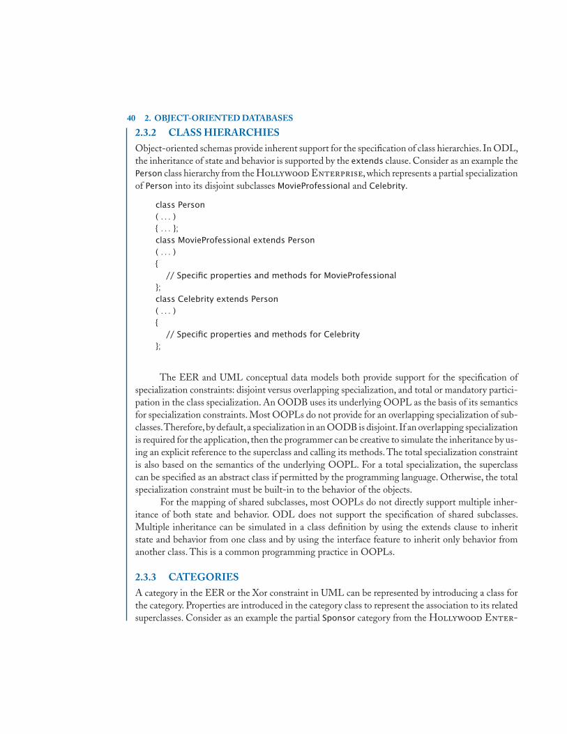
40 2. OBJECT-ORIENTED DATABASES
2.3.2 CLASS HIERARCHIESObject-oriented schemas provide inherent support for the specification of class hierarchies. In ODL,the inheritance of state and behavior is supported by the extends clause. Consider as an example thePerson class hierarchy from the Hollywood Enterprise, which represents a partial specializationof Person into its disjoint subclasses MovieProfessional and Celebrity.
class Person( . . . ){ . . . };class MovieProfessional extends Person( . . . ){
// Specific properties and methods for MovieProfessional};class Celebrity extends Person( . . . ){
// Specific properties and methods for Celebrity};
The EER and UML conceptual data models both provide support for the specification ofspecialization constraints: disjoint versus overlapping specialization, and total or mandatory partici-pation in the class specialization. An OODB uses its underlying OOPL as the basis of its semanticsfor specialization constraints. Most OOPLs do not provide for an overlapping specialization of sub-classes.Therefore,by default, a specialization in an OODB is disjoint. If an overlapping specializationis required for the application, then the programmer can be creative to simulate the inheritance by us-ing an explicit reference to the superclass and calling its methods. The total specialization constraintis also based on the semantics of the underlying OOPL. For a total specialization, the superclasscan be specified as an abstract class if permitted by the programming language. Otherwise, the totalspecialization constraint must be built-in to the behavior of the objects.
For the mapping of shared subclasses, most OOPLs do not directly support multiple inher-itance of both state and behavior. ODL does not support the specification of shared subclasses.Multiple inheritance can be simulated in a class definition by using the extends clause to inheritstate and behavior from one class and by using the interface feature to inherit only behavior fromanother class. This is a common programming practice in OOPLs.
2.3.3 CATEGORIESA category in the EER or the Xor constraint in UML can be represented by introducing a class forthe category. Properties are introduced in the category class to represent the association to its relatedsuperclasses. Consider as an example the partial Sponsor category from the Hollywood Enter-

2.3. MAPPING OBJECT-ORIENTED CONCEPTUAL MODELS TO ODL 41
prise where a Sponsor is either a Person or a Company. A unidirectional association, modeled asan attribute in ODL, is added to the category class for each class participating in the category. TheSponsor class has two attributes: personSponsor and companySponsor. Only one of the unidirec-tional attributes can have a value, indicating the type of the Sponsor category as either a Person ora Company. The other unidirectional attribute must always be null since a Sponsor cannot be botha Person and a Company. This category constraint must be implemented within the behavior of the(Sponsor) category class.
class Person( extent persons
key . . . ){ . . . };class Company( extent companies
key . . . ){ . . . };class Sponsor( extent sponsors ){ attribute Person personSponsor;
attribute Company companySponsor;. . .
};
When the category is partial, the unidirectional association is preferable. It is still possible tofind out whether a person or company is a sponsor and the projects that they sponsor by navigatingthe unidirectional associations from the Sponsor class. If the category is total, requiring that eachsuperclass participates in the category, then the category associations can be implemented usingbidirectional relationships. The relationship provides an explicit access path to the category class.The behavior of the superclasses must enforce the total categorization constraint by verifying thatthe relationship value to the category class is not null. Again, the category class must enforce theexclusive-or constraint of the category.
2.3.4 CHECKPOINT: MAPPING TO ODLAn object-oriented database schema provides inherent support for most of the constraints specifiedin the object-oriented conceptual data models. The constraints that are not captured in ODL mustbe implemented as part of the behavior of the object. Figure 2.3 gives the ODL mapping of theHollywood Enterprise. Figure 2.4 provides the UML diagram that corresponds to the ODLspecification. Since ODL does not inherently support overlapping subclasses, the specialization ofCelebrity into the MovieStar and Model subclasses are now disjoint. The Paid association class ofFigure 2.4 is represented as a reified association, which corresponds to its ODL specification. Since

42 2. OBJECT-ORIENTED DATABASES
the Sponsor category is not total, the associations relating a Sponsor to its corresponding superclassare unidirectional.
2.4 THE ODMG OBJECT QUERY LANGUAGEOQL is based on the SQL industry-standard query language for relational databases. In SQL, thebasic select-from-where clause selects a list of attributes from the specified tables where a conditionholds.The from clause specifies the tables that are relevant to answering the query, allowing for tablealiases or variables to range over tuples of a table. The where clause describes the conditions thatmust hold on the data in the tables to be selected as a result of the query. The select clause gives alist of attributes from the relevant tables that are to appear in the query result.
OQL also has the familiar format of the select-from-where clause. Since OQL is based on anobject model, the from clause specifies the collections of objects that are relevant to answering thequery and uses variables to range over the relevant object collections. Recall that the ODL providesfor the definition of an extent, and the name of an extent denotes a collection of objects of the sametype. Variables in the from clause typically range over extents or the multivalued properties of anobject. The where clause similarly describes the properties that must hold for the data to be in theresult of the query. The select clause in OQL also defines the structure of the result of the query,but OQL’s select clause is more expressive than its relational counterpart, which will be illustratedthrough examples later in this chapter.
To summarize, an OQL query has the following format:
select defines the data to be returned and its structurefrom specifies collections relevant to answering the query and
identifiers to iterate over those collectionswhere specifies conditions for filtering objects
Consider a simple query over the Hollywood schema given in Figure 2.3 that finds thetitles of the movies filmed in “Phoenix”:
select f.titlefrom f in filmProjectswhere f.location = "Phoenix";
The properties of an object are accessed using the familiar dot notation from object-orientedprogramming languages. In the from clause, the variable identifier f ranges over the objects inthe filmProjects extent. The where clause finds the filmProject objects having a location value of“Phoenix”. The select clause returns the title of the selected film projects. Note that the from clausecould have used the SQL-like syntax where the identifier appears after the expression over which thevariable ranges, e.g., filmProjects f. The exposition in this book follows the syntactical conventionof identifier in expression.

2.4. THE ODMG OBJECT QUERY LANGUAGE 43
class Person( extent people
key pId ){ attribute string pId;
attribute string name;attribute string gender;attribute string phone;attribute string address;attribute Person isMarriedTo; . . .
};class MovieProfessional extends Person( extent movieProfessionals){ attribute string company; . . .
}class Celebrity extends Person( extent celebrities ){ attribute date birthDate;
relationship Agent celebrityAgent inverse Agent::agentFor; . . .
};class MovieStar extends Celebrity( extent movieStars ){ attribute string movieType;
relationship set<FilmProject> actsIn inverse FilmProject::actors; . . .
};class Model extends Celebrity( extent models ){ attribute string preferences;
relationship set<Paid> modelsInProjects inverse Paid::modelOfProject; . . .
};class Critic extends MovieProfessional( extent critics ){ attribute string popularity; . . .
};class Agent extends MovieProfessional( extent agents ){ attribute float agentFee;
relationship set<Celebrity> agentFor inverse Celebrity::celebrityAgent; . . .
};
Figure 2.3: ODL Schema for the Hollywood Enterprise (Continues.)

44 2. OBJECT-ORIENTED DATABASES
class Project( extent projects
key projectId ){ attribute string projectId;
attribute string location;attribute float cost;attribute string type; . . .
};class FilmProject extends Project( extent filmProjects ){ attribute string title;
relationship set<MovieStar> actors inverse MovieStar::actsIn; . . .
};class ModelingProject extends Project( extent modelingProjects ){ attribute string description;
relationship set<Paid> paidModelsinverse Paid::paidByProject;
relationship Sponsor sponsoredBy inverse Sponsor::projectsSponsored; . . .
};class Paid( extent paidModelsInProjects ){ attribute float salary;
relationship Model modelOfProject inverse Model::modelsInProjects;relationship ModelingProject paidByProject inverse ModelingProject::paidModels; . . .
};class Company( extent companies
key cId ){ attribute string cId;
attribute string cName; . . .
};class Sponsor( extent sponsors ){ attribute Person personSponsor;
attribute Company companySponsor;relationship set<ModelingProject> projectsSponsored
inverse ModelingProject::sponsoredBy; . . .
};
Figure 2.3: (Continued.) ODL Schema for the Hollywood Enterprise

2.4. THE ODMG OBJECT QUERY LANGUAGE 45
«persistent»
pldnamegenderphoneaddress
CompanyPerson
0..1isMarriedTo
MovieProfessional
ModelingProject
CelebritybirthDatecompany
MovieStarmovieType
Modelpreferences
AgentagentFee
Criticpopularity
FilmProjecttitle description
Project
{disjoint, mandatory}0..*
0..*
1..1
agentFor
celebrityAgent{disjoint,mandatory}
1..1 sponsored By
0..* projectsSponsored
type
1..*
0..* 1
1..*
1
actors
actsIn
«persistent»
Sponsor«persistent»
«persistent» «persistent» «persistent» «persistent»
«persistent»«persistent»
«persistent»
«persistent» «persistent»
Paidsalary
«persistent»
{disjoint} {xor}personSponsor
companySponsor
sponsor
1
0..1sponsor
0..1
1
cldcName
projectldlocation cost
paidByProject
paidModels
modelsInProjects
modelsOfProject
Figure 2.4: UML Diagram for the ODL Specification of the Hollywood Enterprise

46 2. OBJECT-ORIENTED DATABASES
2.4.1 PATH EXPRESSIONSPath expressions allow navigation from one object to another. OQL uses either the dot (.) notationor the arrow (→) notation to indicate a path expression. For example, assume that the variable cis defined over the Celebrity class. The following path expressions return the name of the agent’sspouse for the celebrity given by c:
• c.celebrityAgent.isMarriedTo.name
• c→celebrityAgent→isMarriedTo→name
The property celebrityAgent denotes the Agent of the celebrity. Since an Agent is a Person,the isMarriedTo property denotes the Person married to the agent. The name property gives thename of the spouse. Rather than using multiple notations, this book follows the convention of usingdot notation for path expressions.
In the preceding example, the properties in the path expressions were single-valued attributes.OQL does not allow path expressions to traverse over multivalued attributes and relationships. Thequery must be expressed so that all variables over multivalued properties are explicitly defined in thefrom clause.
Consider as an example a query to retrieve the names of movie stars that appear in film projectslocated in “Phoenix”:
select a.namefrom f in filmProjects,
a in f.actorswhere f.location = "Phoenix";
The variable identifier a is introduced in the from clause to range over the actors multivaluedproperty of a filmProject that is located in “Phoenix”. The actors property is a set of MovieStar
objects that act in the film project. Since a MovieStar is a Person, the select clause returns the name
of the actor.
2.4.2 OQL EXPRESSIONS AND QUERY RESULTSIn the examples of OQL presented so far, the select clause looks quite similar to that of SQL. Queryresults in SQL are a collection of tuples or structures that are formed by listing the desired attributes.If the keyword distinct is used, the collection is a set of tuples. Otherwise, the collection is a multisetor bag of tuples, allowing duplicate elements. However, the results of query expressions in OQL aremore expressive than in SQL.
Expressions in OQL yield atoms, structures, collections, and literals as results. The type of aresult can be inferred from the query expression.The result type of the previous example that retrievesthe names of movie stars appearing in film projects located in “Phoenix” is bag < string >.
The select clause in OQL can return a collection of structured results. Consider the querythat retrieves the name of the actor and the actor’s agent for each actor in the film project named“Days of Thunder”:

2.4. THE ODMG OBJECT QUERY LANGUAGE 47
select struct( movieStarName: a.name,agentName: a.celebrityAgent.name )
from f in filmProjects, a in f.actorswhere f.title = "Days of Thunder";
For each field of the structure, the label is specified along with the source of the field. In this case,the label for the name of the movie star is movieStarName, and the label for the name of the actor’sagent is agentName. The result type of the query is
bag < struct (movieStarName : string, agentName : string) >.
Consider another query that returns a collection of sponsor objects along with the set of thesponsored modeling projects:
select struct( sponsorObject: s, projectsOf: s.projectsSponsored )from s in sponsors;
The result type of the query is
bag < struct (sponsorObject : Sponsor, projectsOf : set < ModelingP roject >) >.
Queries do not always have to use the select-from-where clause. A database extent (e.g.,filmProjects) is a valid OQL query expression. Other examples of valid OQL queries that do notuse the select-from-where syntax include path expressions involving a named persistent object as adatabase entry point.
2.4.2.1 Define StatementThe define statement gives a persistent name to a query expression. The define statement is similarto a view in SQL. For example, the object phxFilms is defined as the collection of film projectslocated in “Phoenix”:
define phxFilms asselect ffrom f in filmProjectswhere f.location = "Phoenix";
Although this query is similar to the query that returned the titles of the film projects locatedin “Phoenix”, this query returns the corresponding FilmProject objects. The type of phxFilms isbag < FilmP roject >.
The define statement can also be used to identify a named persistent object. In the followingexample, the name daysOfThunder is defined as the film project whose title is “Days of Thunder”.The subquery returns a bag of FilmProject objects. The element operator returns a singleton of typeFilmProject. Note that an error results if there is more than one object in the operand to the elementoperator. In this case, an error occurs if there is more than one film project having the name “Daysof Thunder”.
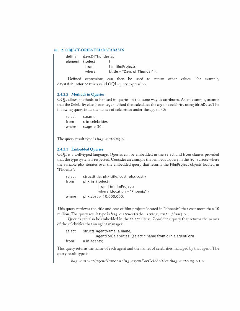
48 2. OBJECT-ORIENTED DATABASES
define daysOfThunder aselement ( select f
from f in filmProjectswhere f.title = "Days of Thunder" );
Defined expressions can then be used to return other values. For example,daysOfThunder.cost is a valid OQL query expression.
2.4.2.2 Methods in QueriesOQL allows methods to be used in queries in the same way as attributes. As an example, assumethat the Celebrity class has an age method that calculates the age of a celebrity using birthDate.Thefollowing query finds the names of celebrities under the age of 30:
select c.namefrom c in celebritieswhere c.age < 30;
The query result type is bag < string >.
2.4.2.3 Embedded QueriesOQL is a well-typed language. Queries can be embedded in the select and from clauses providedthat the type system is respected. Consider an example that embeds a query in the from clause wherethe variable phx iterates over the embedded query that returns the FilmProject objects located in“Phoenix”:
select struct(title: phx.title, cost: phx.cost )from phx in ( select f
from f in filmProjectswhere f.location = "Phoenix" )
where phx.cost > 10,000,000;
This query retrieves the title and cost of film projects located in “Phoenix” that cost more than 10million. The query result type is bag < struct (tit le : string, cost : f loat) >.
Queries can also be embedded in the select clause. Consider a query that returns the namesof the celebrities that an agent manages:
select struct( agentName: a.name,agentForCelebrities: (select c.name from c in a.agentFor))
from a in agents;
This query returns the name of each agent and the names of celebrities managed by that agent. Thequery result type is
bag < struct (agentName :string, agentForCelebrities :bag < string >) >.

2.4. THE ODMG OBJECT QUERY LANGUAGE 49
2.4.3 SET MEMBERSHIP AND QUANTIFICATIONOQL also supports queries involving set membership as well as existential and universal quantifi-cation. The type of these queries is a Boolean value: true or false.
Queries testing membership in a set use the syntax
e in c
returning true if the element e is in the collection c. Consider as an example the query thatdetermines whether daysOfThunder is in phxFilms:
daysOfThunder in phxFilms;
OQL allows for queries involving quantification, both existential and universal. The syntaxfor existential quantification is
exists i in c: exp
returning true if at least one element of the collection c satisfies the exp expression, where thevariable i iterates over elements in the collection. For example, the following query determineswhether there any film projects located in “Phoenix”:
exists f in filmProjects: f.location = "Phoenix";
Consider a more complicated query that identifies those models that have at least one modelingproject located in “Phoenix”.
select modelName: m.namefrom m in modelswhere exists p in m.modelsInProjects:
p.paidByProject.location = "Phoenix";
The query returns the name of a model if there exists a modeling project for that model that islocated in “Phoenix”.
The syntax for universal quantification is
for all i in c: exp
returning true if all elements in the collection c satisfy the exp expression. As an example, thefollowing query tests whether all film projects cost more than $10 million.
for all f in filmProjects: f.cost > 10,000,000;
The query below lists the movie stars for which all of their film projects cost more than $20million, illustrating the use of the universal quantifier in the where clause of a query.
select m.namefrom m in movieStarswhere for all fp in m.actsIn: fp.cost > 20,000,000;

50 2. OBJECT-ORIENTED DATABASES
As a more complex example, consider a query that uses both existential and universal quantifi-cation to find the name of the companies for which all of their sponsored modeling projects includeat least one male model:
select s.companySponsor.cNamefrom s in sponsorswhere s.companySponsor <> null and
for all mp in s.projectsSponsored:(exists p in mp.paidModels: p.modelOfProject.gender = "M");
2.4.4 ORDERINGOQL provides the familiar order by clause with the keywords asc and desc used to specify ascendingor descending order, respectively.The following query provides a list in descending order of the costsof film projects located in “Phoenix” along with the title of the film:
select struct(phxTitle: fp.title, phxCost: fp.cost)from fp in filmProjectswhere fp.location = "Phoenix"order by fp.cost desc;
When ordering is used, the collection is considered a list, which is a sequenced collection.The resulttype of the example query is list < struct (phxT itle : string, phxCost : f loat) >.
The order by clause can also be used in embedded queries to generate a list. The query belowprovides an alphabetical order of movie stars for each film project filmed in “Phoenix”:
select struct( phxTitle: fp.title,phxMovieStars: ( select ms.name
from ms in fp.actorsorder by ms.name ))
from fp in filmProjectswhere fp.location = "Phoenix"order by fp.title asc;
The query result type is
list < struct (phxT itle : string, phxMovieStars : list < string >) >.
2.4.5 USING COLLECTIONSCollections are an important feature of OODBs. OQL provides explicit operators for extractingelements from a collection and for manipulating collections. Earlier in the chapter when definingthe persistent named object daysOfThunder, the element operator illustrated the extraction of anelement from a collection that consisted of a singleton. A singleton collection is common when thequery is selecting an object based on the value of the key. Note that an error results if there is morethan one object in the operand to the element operator.
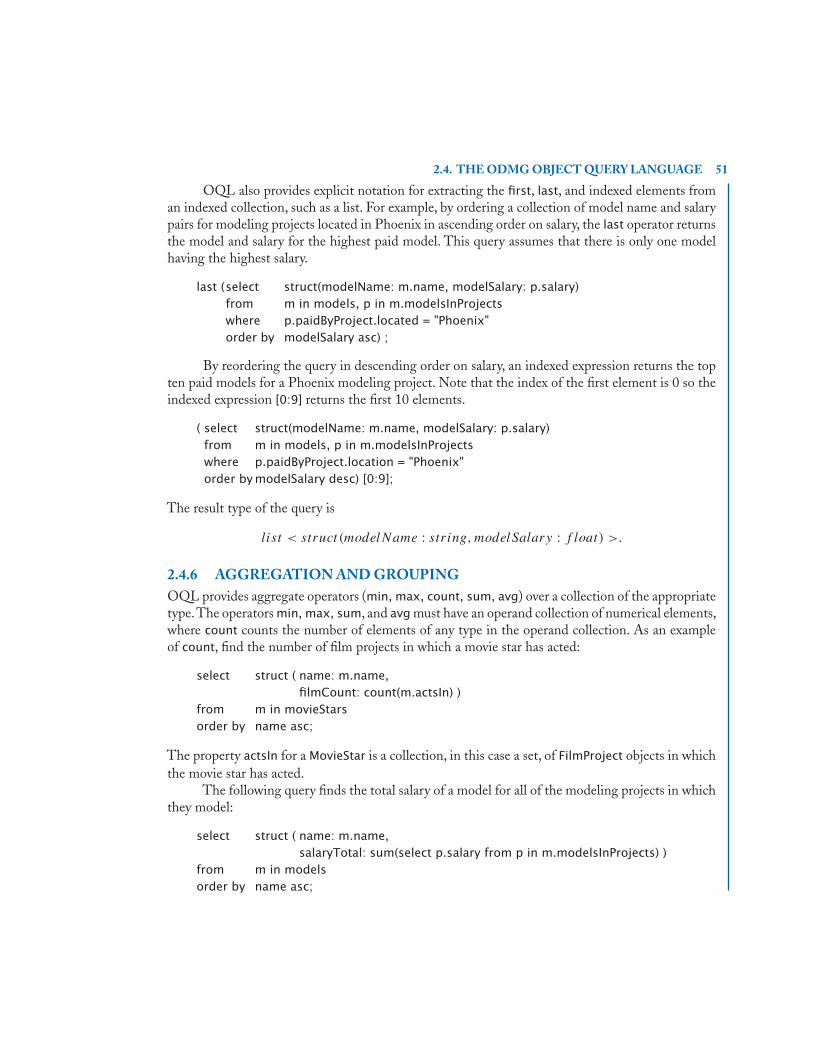
2.4. THE ODMG OBJECT QUERY LANGUAGE 51
OQL also provides explicit notation for extracting the first, last, and indexed elements froman indexed collection, such as a list. For example, by ordering a collection of model name and salarypairs for modeling projects located in Phoenix in ascending order on salary, the last operator returnsthe model and salary for the highest paid model. This query assumes that there is only one modelhaving the highest salary.
last (select struct(modelName: m.name, modelSalary: p.salary)from m in models, p in m.modelsInProjectswhere p.paidByProject.located = "Phoenix"order by modelSalary asc) ;
By reordering the query in descending order on salary, an indexed expression returns the topten paid models for a Phoenix modeling project. Note that the index of the first element is 0 so theindexed expression [0:9] returns the first 10 elements.
( select struct(modelName: m.name, modelSalary: p.salary)from m in models, p in m.modelsInProjectswhere p.paidByProject.location = "Phoenix"order by modelSalary desc) [0:9];
The result type of the query is
list < struct (modelName : string, modelSalary : f loat) >.
2.4.6 AGGREGATION AND GROUPINGOQL provides aggregate operators (min, max, count, sum, avg) over a collection of the appropriatetype.The operators min, max, sum, and avg must have an operand collection of numerical elements,where count counts the number of elements of any type in the operand collection. As an exampleof count, find the number of film projects in which a movie star has acted:
select struct ( name: m.name,filmCount: count(m.actsIn) )
from m in movieStarsorder by name asc;
The property actsIn for a MovieStar is a collection, in this case a set, of FilmProject objects in whichthe movie star has acted.
The following query finds the total salary of a model for all of the modeling projects in whichthey model:
select struct ( name: m.name,salaryTotal: sum(select p.salary from p in m.modelsInProjects) )
from m in modelsorder by name asc;

52 2. OBJECT-ORIENTED DATABASES
Since OQL is well-typed, the use of aggregation over a collection is more intuitive thanaggregation in SQL, which requires understanding the implicit operation of the aggregation inconjunction with the group by clause. SQL also requires that any non-aggregate attribute in theselect clause appear in the group by clause. The group by clause in OQL, although similar to thecorresponding clause in SQL, provides an explicit reference to the collection of objects within eachgroup or partition.
The result type of a grouping specification is always of the type
set < struct (groupingF ields, partition : bag < struct (f romI terators) >) >
where
• groupingFields consists of the fields and their types in the group by clause,
• partition is a distinguished field representing the result of the grouping, and
• fromIterators consists of the variables and their types used in the from clause to iterate overcollections.
Consider the following query that returns a count and a set of the models that an agentrepresents by grouping the models based on the name of the model’s agent:
select struct( agentName: m.celebrityAgent.name,modelCount: count(partition),modelNames: (select p.m.name from p in partition))
from m in modelsgroup by agentName: m.celebrityAgent.name;
The result type of the grouping specification is
set < struct (agentName : string, partition : bag < struct (m : Model) >) >
For each group given by the agentName, there is a distinguished field called partition that givesthe values of the iterator variables used in the from clause using a structure. To find the number ofmodels that the agent represents, the aggregate operator count counts the number of models in thepartition. To retrieve the names of the models from the group, the select clause uses an embeddedquery to iterate over the elements in the partition. Since the partition always returns a structureconsisting of the variables in the from clause, dot notation (p.m.name) is used to access a fieldfrom within the group. The result type of a group by query is always a set since there is exactly onepartition for each value of the grouping fields. The result type of the example query is
set < struct (agentName : string, modelCount : integer, modelNames : bag < string >) >
Just as in SQL, a having clause filters the partitioned sets. To return only the agents thatrepresent more than 3 models, append the following having clause to the prior query specification:
having count(partition) > 3

2.5. CASE STUDY: LINQ AND DB4O 53
2.4.7 CHECKPOINT: OQLAlthough OQL looks similar to the SQL industry standard, it is important to think out of the rela-tional box when answering queries in OQL. Consider the query to retrieve the name and preferencesof models who work on modeling projects located in “Phoenix”. As in SQL, there are several ways tocorrectly answer this query in OQL. One solution is to start from the models extent and determinewhether the model models in projects that are located in "Phoenix":
select struct( modelName: m.name,modelPreferences: m.preferences )
from m in models, p in m.modelsInProjectswhere p.paidByProject.location = "Phoenix";
Another solution is to start from modeling projects that are located in “Phoenix” and find thecorresponding models:
select struct( modelName: p.modelOfProject.name,modelPreferences: p.modelOfProject.preferences )
from mp in modelingProjects, p in mp.paidModelswhere mp.location = "Phoenix";
Both of these solutions represented an object-oriented approach that navigates through the associ-ations between objects.
2.5 CASE STUDY: LINQ AND DB4OThe OQL of the ODMG contributes a test bed for the study of query optimization techniques forobject databases and a database independent way to describe declarative queries over the ODMGobject model. Although the OQL standard was only implemented in research prototypes ratherthan commercial OODBs, it provides an important foundation for declarative querying capabilitiesover objects.There are more similarities than differences between OQL and the recently introducedLanguage INtegrated Query (LINQ) language embedded into the OOPLs of the .NET Framework.Both languages rely on the well-typed features of the underlying OOPL, e.g., applying aggregateoperators to a collection of the appropriate type. LINQ is a declarative query language that isseamlessly integrated into the OOPLs of the .NET Framework, which include C# and VisualBasic. LINQ can query collections of objects, tuples, or XML elements. In this case study, the focusis on querying a collection of objects using the C# language. Therefore, the fields of the classes areimplemented as properties in C#, which are conventionally indicated by a method with an initialuppercase letter that defines get and set accessors for the private instance field that the propertyis encapsulating. The private instance field usually has the same name but starts with an initiallowercase letter. The case study concludes with an overview of the db4o open-source OODB andthe use of LINQ for db4o native queries in C#.

54 2. OBJECT-ORIENTED DATABASES
2.5.1 LINQLINQ builds on the familiarity of SQL and OQL with from-where-select clauses that follow theunderlying execution order of the query:
from specifies collections relevant to answering the query andidentifiers to iterate over those collections
where specifies conditions for filtering objectsselect defines the structure of the data to be returned
LINQ also uses the familiar path expressions with dot notation to access properties or methodsassociated with objects. The query to find the titles of the movies filmed in “Phoenix” in LINQ is:
from f in filmProjectswhere f.Location == "Phoenix"select f.Title;
Note that the from and where clauses in LINQ are not limited to occur once in the expression,and the clauses can be intertwined, as in the following query to find the actors who starred in projectsfilmed in “Phoenix”:
from f in filmProjectswhere f.Location == "Phoenix"from a in f.Actorsselect a.Name;
LINQ’s querying capabilities are provided by the underlying .NET framework,which includesextension methods. An extension method is a static method in a static class that can be invoked asif it were an instance method on the object itself. The familiar from-where-select syntax in LINQ,which is called query comprehension syntax, is compiled into an extension method syntax. For example,Where and Select are extension methods.Therefore, the underlying extension method syntax for thequery returning titles of movies filmed in “Phoenix” is the following:
filmProjects.Where(f => f.Location == "Phoenix").Select(f => f.Title);
The Where extension method is invoked on the filmProjects extent, taking as an argument ananonymous function that filters the extent. The => syntax is read as “goes to” and represents a wayto pass an argument into an anonymous function similar to lambda expressions. The Select methodreturns the Title of the filtered collection.
The collection of extension methods that perform operations on LINQ query expressions arecalled query operators. As will be shown in the following examples, queries typically use a combinationof query comprehension syntax with query operators.

2.5. CASE STUDY: LINQ AND DB4O 55
2.5.1.1 Query ResultsAn important feature of the underlying framework used by LINQ is implicitly typed variables. Thekeyword var defines a variable with an implicit type. Consider defining the variable phxFilms as thecollection of film projects located in “Phoenix”:
var phxFilms =from f in filmProjectswhere f.Location == "Phoenix"select f;
In C#, the type of the collection returned is usually an instance of IEnumerable<T>.This expositionwill continue to use the generic term collection rather than emphasize the C# type system, which isnot required to understand the fundamentals of LINQ. This is consistent with the earlier discussionof OQL, in which the particular language binding was not discussed.The type of the collections weredescribed using the terms bag and set. Recall that a bag is a collection that may contain duplicateelements, and a set is a collection that does not contain duplicate elements. To remove duplicateelements from a collection in LINQ, the Distinct operator is used. For example, the following queryreturns the set of movie stars that appeared in Phoenix film projects:
( from f in phxFilmsfrom a in f.Actorsselect a).Distinct();
In addition to collections, LINQ can return a single object, with its type being implicitlydefined. Consider defining a variable daysOfThunder that represents the unique FilmProject objectwith the title “Days of Thunder”:
var daysOfThunder =( from f in filmProjectswhere f.Title == "Days of Thunder"select f ).Single();
This query illustrates the use of the Single operator that returns the single object from a collection,throwing an exception if there is more than one object in the collection to which it is applied.
LINQ query expressions return structured results using the features of anonymous types andobject initialization. The following query returns an anonymous type that contains the names ofmovie stars in the daysOfThunder film along with the name of each movie star’s agent:
from a in daysOfThunder.Actorsselect new { movieStarName = a.Name,
agentName = a.CelebrityAgent.Name };
The anonymous type feature is illustrated by the new operator in the select clause, creating ananonymous type. The braces enclose the initialization of the anonymous object using names, which

56 2. OBJECT-ORIENTED DATABASES
is in contrast to conventional constructors for named classes that use the position of the parameterin the call to the constructor for initialization.
Queries can use method calls as shown in the following query that finds celebrities who areyounger than 30:
from c in celebritieswhere c.Age() < 30select c.Name;
LINQ also supports embedded queries in the from or select clauses. Consider as an examplea query embedded in the from clause to find the “Phoenix” film projects, which is then filtered fora cost greater than $10 million:
from phx in ( from f in filmProjectswhere f.Location == "Phoenix"select f)
where phx.Cost > 10,000,000select new { phx.Title, phx.Cost };
Queries can also be embedded in the select clause. This query returns the names of thecelebrities that an agent manages:
from a in agentsselect new { agentName = a.Name,
agentForCelebrities = (from c in a.AgentFor select c.Name) };
2.5.1.2 Set Membership and QuantificationLINQ also supports set membership and quantification queries using query operators, such asContains, Any, and All.
The following query returns a Boolean result of true if the collection phxFilms contains thefilm project daysOfThunder, using the Contains operator on phxFilms with daysOfThunder as aparameter:
phxFilms.Contains(daysOfThunder);
The Any operator supports existential quantification. In the following example, an anonymousfunction is a parameter to the Any operator, returning true if there is any f in filmProjects havinga Location value equal to “Phoenix”:
filmProjects.Any(f => f.Location == "Phoenix");
As a more complicated example, consider the query that finds the models who have had atleast one modeling project located in “Phoenix”:
from m in modelswhere (m.ModelsInProjects).Any(p => p.PaidByProject.Location == "Phoenix")select new {modelname = m.Name};

2.5. CASE STUDY: LINQ AND DB4O 57
The All operator supports universal quantification. In this simple example, an anonymousfunction determines whether all f objects in filmProjects cost more than 10 million:
filmProjects.All(f => f.Cost > 10000000);
Consider another query that illustrates the use of the All operator, finding the names of moviestars for which all of their film projects cost more than $20 million:
from m in movieStarswhere (m.ActsIn).All(fp => fp.Cost > 20000000)select m.Name;
As a more complicated example, the following query combines universal and existential quan-tification by finding the sponsors that are companies for which all of their sponsored modelingprojects include at least one male model:
from s in sponsorswhere s.CompanySponsor ! = null &&
(s.ProjectsSponsored).All(mp =>
(mp.PaidModels).Any(p => p.ModelOfProject.Gender == "M"))select s.CompanySponsor.CName;
2.5.1.3 OrderingAnother common construct in a query language is the capability to order results. In LINQ, orderby
is one word, and the keywords ascending and descending specify the result order, with ascending
as the default. The orderby clause occurs before the select clause, allowing the results to be orderedby data that is not contained in the query result. The following query provides a list of film projectsfilmed in “Phoenix” sorted in descending order by the cost of the project.
from fp in filmProjectswhere fp.Location == "Phoenix"orderby fp.Cost descendingselect new { phxTitle = fp.Title, phxCost = fp.Cost};
The orderby clause can also be used in embedded queries. The query below returns a list ofmovie stars in alphabetical order for each film project filmed in “Phoenix”:
from fp in filmProjectswhere fp.Location == "Phoenix"orderby fp.Title ascendingselect new { phxTitle = fp.Title,
phxMovieStars = ( from ms in fp.Actorsorderby ms.Nameselect ms.Name ) };

58 2. OBJECT-ORIENTED DATABASES
2.5.1.4 Using CollectionsThere are various query operators that are available in LINQ for accessing elements in a collection,such as First, Last, and Take. For example, the following query finds the highest paid Phoenix modelby ordering the collection results in ascending order by salary and choosing the last element in thecollection using the Last operator:
( from m in modelsfrom p in m.ModelsInProjectswhere p.PaidByProject.Location == "Phoenix"orderby p.Salary ascendingselect new {modelName = m.Name, modelSalary = p.Salary}).Last();
As another example, consider a query that finds the top ten models based on the salary receivedfor a modeling project in Phoenix sorted in descending order using the Take operator to return thefirst ten results:
( from m in modelsfrom p in m.ModelsInProjectswhere p.PaidByProject.Location == "Phoenix"orderby p.Salary descendingselect new {modelName = m.Name, modelSalary = p.Salary}).Take(10);
Additional query operators for collections include the set operations of union (Union), inter-section (Intersect), and difference (Except). There are also query operators to perform aggregationover collections.
2.5.1.5 Aggregation and GroupingAggregation in LINQ is a straightforward application of the appropriate operator on the desiredcollection. For example, the Count operator on the ActsIn property of a movie star determines thenumber of films for that movie star:
from m in movieStarsorderby m.Nameselect new {name = m.Name, filmCount = m.ActsIn.Count()};
When using the other aggregate query operators on a collection of numeric elements, suchas Sum, Min, Max, and Average, the operator is applied to an appropriately type collection. Forexample, to find the total salary for a model requires summing the salary from all of the modelingprojects for that model:
from m in modelsselect new { name = m.Name,
salaryTotal = ( from p in m.ModelsInProjectsselect p.Salary ).Sum()};

2.5. CASE STUDY: LINQ AND DB4O 59
The subquery (from p in m.ModelsInProjects select p.Salary) returns a collection of the salary forthat model, on which the Sum operator operates.
There is an alternative to creating the explicit collection of numbers. An anonymous functioncan be used to generate the numeric collection as an argument to the operator. For example, the totalcost of Phoenix film projects can be found using the following query expression:
phxFilms.Sum(phx => phx.Cost);
Another useful feature of LINQ query expressions is the ability to order the query resultsbased on the aggregation. LINQ supports a let clause to define a variable for the scope of the query.Consider ordering the results of the total model salary in descending order based on the computedsalary:
from m in modelslet salaryTotal = m.ModelsInProjects.Sum(p => p.Salary)orderby salaryTotal descendingselect new { name = m.Name,
salaryTotal };
Grouping in LINQ is very different from SQL. Grouping is specified explicitly using a group
clause that specifies what to group and what to group by, returning a collection of groups where eachgroup has a Key property consisting of the value on which the group was created.
Consider a sample query that groups film projects by their location:
var filmsByLocation =from f in filmProjectsgroup f by f.Location;
Subsequent queries can iterate over this collection of groups, as in the following example that returnsthe location, a count of the number of films associated with that location, and the group of films.
from locFilms in filmsByLocationorderby locFilms.Keyselect new { location = locFilms.Key,
numberOfFilms = locFilms.Count(),films = locFilms };
Alternatively, LINQ’s group clause provides an optional into specification to automaticallycontinue the iteration over the groups in one query expression.
from f in filmProjectsgroup f by f.Location into locFilmsorderby locFilms.Keyselect new { location = locFilms.Key,
numberOfFilms = locFilms.Count(),films = locFilms };

60 2. OBJECT-ORIENTED DATABASES
As another example, consider grouping models by their agent, returning for each agent thatrepresents more than three models, the count and names of the models in the group.
from m in modelsgroup m by m.CelebrityAgent into agentGroupwhere agentGroup.Count() > 3select new { agentName = agentGroup.Key.Name,
modelCount = agentGroup.Count(),modelNames = (from mg in agentGroup select mg.Name) };
Note that the filtering of a group is accomplished in LINQ by a where clause following the group-
by-into clause, rather than a having clause as in SQL.
2.5.1.6 Query ExecutionAs discussed earlier, LINQ’s query comprehension syntax is converted to an underlying extensionmethod syntax, resulting in an expression tree that represents the definition of the query. In general,a LINQ query is not executed until it is referenced, decoupling the query construction from itsexecution. This feature is known as deferred query execution. Thus, a LINQ query is similar to adatabase view definition in that it is materialized on each reference.
Deferred query execution provides an opportunity for changing the values of parametersbetween query invocations. Consider defining a variable locationOfInterest and a query expressionfilmsAtLocation that returns the films filmed at the locationOfInterest:
var locationOfInterest = "Phoenix";var filmsAtLocation =
from f in filmProjectswhere f.Location == locationOfInterestselect f;
The first time that filmsAtLocation is referenced it returns the films filmed in “Phoenix”. If thevalue of the variable locationOfInterest is changed to “San Diego”, then a subsequent reference tofilmsAtLocation returns San Diego films.
Note that there are some query operators that force the immediate execution of a query, suchas the operators that return a scalar value (e.g., Average, Count, Max, Min, Sum) or a single elementof a collection (e.g., First, Last, Single). The query developer can also force immediate executionof any query by materializing the query using a conversion operator, such as ToArray or ToList, tocache the results in the designated data structure. These materialized results can then be reusedfor subsequent query references provided that the underlying data on which the materialized querydepends has not changed. Otherwise, the materialized results would be out of date.
2.5.1.7 Checkpoint: LINQLINQ provides a declarative object-based query language within the .NET Framework.This sectionillustrated how to use LINQ to query collections of objects. LINQ can also be used to query

2.5. CASE STUDY: LINQ AND DB4O 61
collections of relational tuples or collections of XML elements. The syntax is essentially the same.For relational databases, once the connection to the database is established, the attributes are accessedusing familiar dot notation. For XML, after loading the XML document, the methods Descendants
and Elements return a collection of elements for querying. LINQ also provides a programmer witha declarative language for programming in C#.
LINQ uses a combination of the more familiar from-where-select query comprehensionsyntax in combination with query operators. Table 2.2 provides a summary of the common queryoperators discussed in this section.
Table 2.2: Summary of LINQ Query Operators.Purpose Query OperatorsSet Membership and Quantification All, Any, Contains
Accessing Elements First, Last, Single, Take
Sets Distinct, Except, Intersect, Union
Aggregation Average, Count, Max, Min, Sum
2.5.2 DB4OThe db4o open-source OODB is a simple yet powerful system that is typically used as an embeddablestandalone database, although it also supports a client/server mode. db4o is cross-platform and workswith both the C# and Java OOPLs. It supports the ACID transaction properties as well as replicationand synchronization of objects. db4o is typically used in application areas that have data consistingof complex object structures where data typically belongs to the application.
The db4o database takes a simpler approach for persistence than the approach representedby the ODMG standard and other OODB products that use an ODL-like schema specificationcompiled into language-specific bindings for a particular OOPL. db4o does not have a separateschema specification. Any class defined in the OOPL can be stored in the database explicitly usingthe db4o API.
The use of db4o requires either adding a reference to the dynamic link library (dll) for C#or adding the Java archive (jar file) to the classpath for Java. In addition, the Db4objects.Db4o
namespace (package) must also be used (imported). This case study will continue to use the C#language for examples and to use the method names as documented in the 7.12 version of db4o forthe .NET Framework 3.5, which supports LINQ. Typically, the only difference between the db4oAPI method names is the case of the initial letter, as C# uses PascalCase with an initial uppercaseletter and Java uses camelCase with an initial lowercase letter.
To create a db4o database, first open a database file using the Db4oFactory class as shown:
IObjectContainer db = Db4oFactory.OpenFile("Hollywood.yap");
An IObjectContainer represents the db4o database, and the variable db provides a reference to thedatabase. Each IObjectContainer manages object identity and has its own transaction. The opening

62 2. OBJECT-ORIENTED DATABASES
of the database represents the start of a transaction.When the database is closed using db.Close(), thetransaction is committed. To define a transaction scope with a finer granularity than that providedby the opening and closing of the database, try-catch blocks can be used to commit a completedtransaction or to rollback the transaction when an exception occurs using the Commit() and Rollback()methods of the IObjectContainer.
try{
database operations here}catch (Exception e){
db.Rollback();}finally{
db.Commit();}
Storing objects in the database uses the Store method of the db4o API, which was known asthe Set() method in earlier versions of db4o. Once an object is constructed in main memory, it canbe explicitly stored in the database. For example, assuming that the variable model111 references anon-null Model object in main memory, then db.Store(model111) stores the object model111 andany objects that it references in the database, if the referenced object is not already stored in the db4odatabase.
The db4o system provides several ways to retrieve objects from the database, which requiresthe use of the Db4objects.Db4o.Query namespace (package). One method uses a Query By Example(QBE) mechanism to retrieve objects based on a template object. For example, to find a film projectlocated in “Phoenix”, a template object is created with a location of “Phoenix” with default valuesfor the remaining properties (null for objects and 0 for numeric fields):
FilmProject phxFilmTemplate =new FilmProject {
Location = "Phoenix",ProjectId = null,Cost = 0,Title = null,Type = null };
IObjectSet result = db.QueryByExample(phxFilmTemplate);
This example shows the object initialization feature of the .NET Framework allowing for initializingan object’s properties by name rather than by position.The QueryByExample method, Get() in earlier
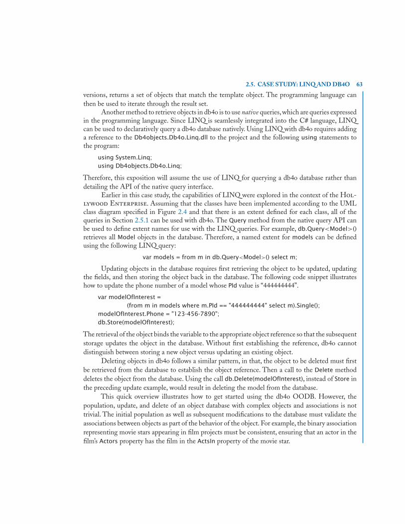
2.5. CASE STUDY: LINQ AND DB4O 63
versions, returns a set of objects that match the template object. The programming language canthen be used to iterate through the result set.
Another method to retrieve objects in db4o is to use native queries,which are queries expressedin the programming language. Since LINQ is seamlessly integrated into the C# language, LINQcan be used to declaratively query a db4o database natively. Using LINQ with db4o requires addinga reference to the Db4objects.Db4o.Linq.dll to the project and the following using statements tothe program:
using System.Linq;using Db4objects.Db4o.Linq;
Therefore, this exposition will assume the use of LINQ for querying a db4o database rather thandetailing the API of the native query interface.
Earlier in this case study, the capabilities of LINQ were explored in the context of the Hol-lywood Enterprise. Assuming that the classes have been implemented according to the UMLclass diagram specified in Figure 2.4 and that there is an extent defined for each class, all of thequeries in Section 2.5.1 can be used with db4o. The Query method from the native query API canbe used to define extent names for use with the LINQ queries. For example, db.Query<Model>()retrieves all Model objects in the database. Therefore, a named extent for models can be definedusing the following LINQ query:
var models = from m in db.Query<Model>() select m;
Updating objects in the database requires first retrieving the object to be updated, updatingthe fields, and then storing the object back in the database. The following code snippet illustrateshow to update the phone number of a model whose PId value is “444444444”.
var modelOfInterest =(from m in models where m.PId == "444444444" select m).Single();
modelOfInterest.Phone = "123-456-7890";db.Store(modelOfInterest);
The retrieval of the object binds the variable to the appropriate object reference so that the subsequentstorage updates the object in the database. Without first establishing the reference, db4o cannotdistinguish between storing a new object versus updating an existing object.
Deleting objects in db4o follows a similar pattern, in that, the object to be deleted must firstbe retrieved from the database to establish the object reference. Then a call to the Delete methoddeletes the object from the database. Using the call db.Delete(modelOfInterest), instead of Store inthe preceding update example, would result in deleting the model from the database.
This quick overview illustrates how to get started using the db4o OODB. However, thepopulation, update, and delete of an object database with complex objects and associations is nottrivial. The initial population as well as subsequent modifications to the database must validate theassociations between objects as part of the behavior of the object. For example, the binary associationrepresenting movie stars appearing in film projects must be consistent, ensuring that an actor in thefilm’s Actors property has the film in the ActsIn property of the movie star.

64 2. OBJECT-ORIENTED DATABASES
2.6 CHECKPOINTObject-oriented databases are an alternative data model to that provided by the traditional relationaldata model. An object-oriented data model more closely represents the enterprises expressed in anobject-oriented conceptual data model, such as an EER or UML diagram. The ODMG standardprovides a data definition language and declarative query language that forms a foundation forthe discussion and portability of object-oriented databases. The case study illustrated the features ofLINQ and how LINQ can be used as a declarative query language within an OODB implementationusing the db4o open-source database, which provides an embeddable, standalone system supportingobject persistence with transactions.
2.7 BIBLIOGRAPHIC REFERENCESThe Object Data Standard [Cattell et al., 2000] was developed to provide a common ground todescribe an object model, the specification of a schema over the object model, and a query language.There are also several books available that are a collection of papers describing the use of object-oriented databases in practice [Loomis and Chaudhri, 1997] and [Chaudhri and Zicari, 2000].The ODBMS.ORG portal [ODBMS.ORG, 2010] provides free resources for object databases.There are multiple resources available on the LINQ language, from articles for database educa-tors [Dietrich and Chaudhari, 2009] to books for putting LINQ into practice [Calvert and Kulkarni,2009, Marguerie et al., 2008]. There is a lightweight interactive development available for LINQ,known as LINQPad [Albahari, 2010], which provides a straightforward environment for usingLINQ. The open-source db4o database is available on the Web [Versant, 2010], and there are othersources that document its use and applicability in applications [Edlich et al., 2006].

65
C H A P T E R 3
Object-Relational DatabasesSince the introduction of the first commercial relational database products in the early 1980’s,relational database technology has become a multi-billion dollar business.During this growth period,the practical use of relational technology for more complex, non-business-oriented applicationswas challenged in the wake of the object-oriented database movement. Users began to experimentwith the use of relational databases in applications that required data types above and beyond thesimple built-in data types provided by most commercial systems.These non-traditional applicationstypically involved large amounts of data, such as video, audio, and spatial data, and/or complex,hierarchically structured data, such as designs of engineering artifacts. Researchers subsequentlybegan to investigate ways to incorporate object-oriented concepts, such as those covered in Chapter1, into relational database systems, creating object-relational database technology. Whereas, object-oriented database technology provides a revolutionary approach that requires the construction of newobject storage and server facilities, object-relational database technology provides an evolutionaryapproach to the use of objects in databases by building on established relational database researchresults. Today, the SQL standard captures many of these original concepts as object extensionsto the relational standard, with companies such as Oracle, IBM, Informix, and Sybase providingobject-relational products, also known as universal servers.
This chapter presents the object features of the SQL standard and the manner in whichsuch features have been incorporated into the Oracle commercial database product. A fundamentalconcept supporting object extensions to the relational model is that of extensibility through the useof user-defined data types (UDTs). UDTs allow application developers to go beyond the built-in datatypes of the relational model, defining more complex, structured data types that are appropriate tothe application at hand. UDTs in the SQL standard fully support the object-oriented concept ofencapsulation, where users can define methods for manipulating the instances of a UDT. UDTscan also be formed into inheritance hierarchies, supporting inheritance of attributes and methods aswell as the object-oriented concepts of polymorphism and overriding of method implementations.A UDT can then be used in the same way as any other built-in data type: for defining the types ofcolumns in tables, for defining parameters, or for defining variables in SQL routines.
Although UDTs can be used strictly as a means for creating more complex column, variable, orparameter values, UDTs also provide the basis for the creation of objects. UDTs can be used togetherwith a new form of table known as a typed table. When a typed table is formed based on a UDT,the rows of the typed table become objects, with object identifiers that are referred to as references.References can then be used to create object-based associations between typed tables in the sameway that object relationships are formed between classes in an object-oriented database. Coupling

66 3. OBJECT-RELATIONAL DATABASES
the use of object references with the array data type of the SQL standard also supports the creationof multivalued object associations, providing an intuitive way to model 1:N and M:N associationsbetween objects. Typed tables can also be formed into an inheritance hierarchy that corresponds tothe hierarchy of the UDTs on which they are based, thus supporting object inheritance.
This chapter begins with a discussion of the SQL built-in constructed types, such as row typesand arrays, for the construction of more complex values. Although the built-in constructed types arenot part of the object features of the standard, they are useful in support of mapping object-orientedconceptual models to object-relational representations.The chapter then addresses constructed typesin the form of UDTs, illustrating how UDTs and typed tables can be used to take an object-orientedapproach to the design of relational databases. Techniques for mapping EER and UML models tothe object-relational features of the SQL standard are then addressed, followed by a case study ofthe object-relational features of Oracle 11g.
3.1 BUILT-IN CONSTRUCTED TYPES
In addition to atomic types, such as character, integer, real, and Boolean, the SQL standard supportsa category of data type known as constructed types, consisting of user-defined types (UDTs), a referencetype, a row type, and a collection type. Constructed types are data types that are capable of holding morethan one value. Row types and collection types are built-in data types, while UDTs and referencetypes provide a user-defined approach to extending the built-in types that are available in relationaldatabase systems.
This section provides an overview of the built-in row and collection types. Row types andcollection types will be used later in this chapter to support the mapping of object-oriented conceptualmodels to object-relational implementations. Since UDTs and reference types are the main topic ofthis chapter, each of these constructed types are covered in more detail in separate sections.
Examples are presented using the School Database Enterprise in Figure 3.1. As shown inFigure 3.1, each instance of Person has a pId, dob, firstName, and lastName, where pId is theprimary key. Because of the total and disjoint specialization relationship between Person, Student,and Faculty, a Person must be either a Student or a Faculty member, but not both. Each Student
has a status (freshman, sophomore, junior, senior), and each Faculty has a rank (assistant professor,associate professor, professor).
A Department has two attributes: a code and a name, with code being the primary key.Each Student and Faculty instance must be associated with a Department through the majorsIn
or worksIn relationship, respectively. A Department can have a Faculty instance as the departmentchair through the chair relationship. Each Faculty member can serve as the chair of at most oneDepartment. A Faculty instance can only be the chair of the Department in which he/she works.
Each CampusClub has a cId, a name, a location, and a phoneNumber, where cId is theprimary key. A Student can optionally be a member of many CampusClub organizations. Likewise,a CampusClub can have many Student members. A CampusClub can have a Faculty member as anadvisor. Each Faculty member can advise many CampusClub organizations.

3.1. BUILT-IN CONSTRUCTED TYPES 67
Person
Studentstatus
CampusClub
Department
Facultyrank
* *members memberOf
* 0..1advisorOf advisor
advisesclubs
*
major1
{disjoint, mandatory}
0..1
*
worksIn1
chairOf
1deptChair
chair
plddobfirstNamelast Name
cldnamelocationphone
codenamegetFacultygetStudents
Figure 3.1: UML Diagram of the School Database.From Succeeding with Object Databases by AkmalB. Chaudri and Roberto Zicari. Copyright ©2000 by Akmal B. Chaudri and Roberto Zicari. All rightsreserved. Reproduced here by permission of Wiley Publishing, Inc.
3.1.1 ROW TYPESA traditional relational table is composed of rows with the distinguishing characteristic that eachcolumn value in each row must be atomic, which is the basic definition of first normal form (1NF).The SQL standard relaxes the 1NF requirement with the introduction of the row type. The rowtype allows a row to be stored as a column value inside of another row.
Using the School Database Enterprise in Figure 3.1, suppose the location of a cam-pus club consists of a street name, building name, and room number. These three values could berepresented as three separate columns in a table. Using a row type, however, the location of a clubcan be conceptually viewed as one column with a non-atomic value. Each element of the columnis referred to as a field. In the example below, location is identified as a row type with the keywordrow, followed by field name and type pairs enclosed in parentheses and separated by commas.

68 3. OBJECT-RELATIONAL DATABASES
create table campusClub( cId varchar(10),
name varchar(50) not null,location row (street varchar(30), bldg varchar(5), room varchar(5)),advisor varchar(11) references faculty(pId),primary key (cId));
The row constructor is used to assign values to the fields of a row. The values in the rowconstructor can either be a list of values or the result of a query. In either case, the types of thevalues must conform to the field types in the row type definition. The following example illustratesinserting a club into the campusClub table, where the club is located in Room 222 of the BrickyardBuilding on Mill Avenue. The location of the club is represented as one column in the table, butthe location is a non-atomic value composed of three separate character string values.
insert into campusClub values( 'CC123',
'Campus Computer Club',row('Mill Avenue', 'Brickyard Building', 'Rm 222'),'FA123');
The values of a row type can be retrieved using dot notation to access the individual fieldsthat are part of the column. The query below will return the street, building, and room number forthe location of the specified club.
select c.location.street, c.location.bldg, c.location.roomfrom campusClub cwhere c.name = 'Campus Computer Club';
3.1.2 ARRAYS AS COLLECTIONSThe collection type provides an additional way to represent non-atomic values in a relational schema.Theoretically, a collection can be a structure such as an array, a set, a list, or a bag, but the currentversion of the SQL standard only supports the array type.
A column in a table can be specified as an array by following the column type with the array
keyword. The maximum number of elements in an array is enclosed in square brackets. The firstposition in an array is accessed with an index value of one.
Again using the campusClub table as an example, a members array can be used to directlystore the identifiers of the club members inside of each row of the campusClub table.
create table campusClub( cId varchar(10),
name varchar(50) not null,location row (street varchar(30), bldg varchar(5), room varchar(5)),advisor varchar(9) references faculty(pId),

3.1. BUILT-IN CONSTRUCTED TYPES 69
members varchar(11) array[50] references student(pId),primary key (cId));
The array constructor is used to reserve space for an array and can also be used to assign valuesto the array elements.The following insert statement illustrates how to initialize the members arrayto an empty value using the array constructor with no elements.
insert into campusClub values( 'CC123',
'Campus Computer Club',row('Mill Avenue', 'Brickyard Building', 'Rm 222'),'FA123',array[ ]);
The specific identifiers of club members can then be added to the array by using the arrayconstructor in an update statement.The following statement assigns values to the first three positionsin the members array.
update campusClubset members = array['ST111', 'ST222', 'ST333']where name = 'Campus Computer Club';
Assignments can also be made to individual positions in an array by using a specific indexvalue.
update campusClubset members[4] = 'ST444'where name = 'Campus Computer Club';
An index is used to access a specific position of an array. The following query returns theidentifier of the second element of the members array for the specified club.
select members[2]from campusClubwhere name = 'Campus Computer Club';
The cardinality function can be used to get the size of an array. For example, cardinal-
ity(c.members) returns the current size of the members array (assuming c is a cursor to a rowin the campusClub table.). The cardinality function can be used to support iteration through arraycontents within SQL routines.
The cardinality of an array is adjustable, ranging from an empty array to the maximum sizespecified in the array definition. Given the four values that were assigned to the array in the previousexamples, the current cardinality of the array is four. Suppose an additional update statement setsposition six to the value ‘ST666’. Then the cardinality of the array becomes six, with position fiveset to null.
70 3. OBJECT-RELATIONAL DATABASES
In general, arrays are useful for representing multivalued attributes. Arrays can also be usedto directly model the many side of a 1:N or M:N association as in the use of relationships in ODL.In the remainder of this chapter, arrays will be used to illustrate a more object-oriented approach tothe representation of multivalued relationships in an object-relational schema.
3.1.3 CHECKPOINT: BUILT-IN CONSTRUCTED TYPESRow types and arrays extend the pure relational model with capabilities for representing non-atomic values in table columns. Row types are useful for representing composite values, whereeach component of the row type is of a possibly different data type. Arrays can be used to representan indexed collection of values with a homogeneous data type.
3.2 USER-DEFINED TYPES
The term user-defined type (UDT) is the SQL standard terminology for abstract data type. Mostreaders should already be familiar with the concept of abstract data types, where users define newtypes having some form of internal structure together with methods that represent the behavior ofthe type.The internal representation of the type is encapsulated by the behavior of the type, meaningthat the internal implementation of the type is hidden from the outside world and can even changewithout affecting the manner in which a user interfaces with the type. UDTs in the SQL standardare somewhat different from the strict definition of an abstract data type since all internal attributesof a UDT and their associated methods are public and cannot be marked as protected or private as inlanguages such as Java or C++.The primary advantage of a UDT is that it allows database developersto define new application-oriented types, above and beyond built-in atomic and constructed types,that can be used in the definition of relational tables. UDTs also provide the basis for the creationof objects in the relational world.
This section describes the two basic types of UDT in the SQL standard: the distinct type andthe structured type. The syntax for defining a UDT using the create type statement is presented inFigure 3.2. The details of the syntax will be addressed in the subsections that follow.
3.2.1 DISTINCT TYPESA distinct type provides a way of attaching special meaning to an existing atomic type. Once adistinct type is defined, use of the type cannot be freely mixed with the atomic type on which it isbased. The distinct type essentially defines a new form of the atomic type.
As an example, suppose you need a table that maintains the age and weight of each personin a database. You could always define columns for personAge and personWeight that are of typeinteger. You could then add the age and weight of the person, since both values are of the same type,even though the addition of the two values is meaningless.

3.2. USER-DEFINED TYPES 71
create type <user_defined_type_body>
<user_defined_type_body> ::= <user_defined_type_name> [under <user_defined_type_name>] [as <representation>] [ [not] instantiable] [not] final [ref is system generated | ref using <predefined type> | ref from <attribute_name> [{,attribute_name}...]] [<method_specification_list>]
<representation> ::= <predefined_type> | <member_list>
<member_list> ::= (<attribute_definition> [{, <attribute_definition>} …])
<attribute_definition> ::= <attribute_name> {<data_type> | <collection_type>} [<reference_scope_check>] [default <default_value>]
<data_type> ::= <predefined_type> | <reference_type>
<collection_type> ::= <data_type> array [unsigned_integer] /* [ ] part of syntax*/ <method_specification_list> ::= <method_specification> [{ ,<method_specification>}…]
<method_specification> ::= <partial_method_specification> | <overriding_method_specification>
<overriding_method_specification> ::= overriding <partial_method_specification>
<partial_method_specification> ::= [constructor] method <method_name> <SQL_parameter_declarations> returns <data_type>
Figure 3.2: SQL Syntax for Creating User-Defined Types
To prevent meaningless calculations with values that are of the same type but conceptuallyhave different semantics, distinct types can be defined using the create type statement in Figure 3.2.In the example below, age and weight are defined as two different distinct types, both based on theinteger atomic type using the as clause of the create type statement.
create type age as integer final;create type weight as integer final;

72 3. OBJECT-RELATIONAL DATABASES
create table person( personId varchar(3),
personAge age,personWeight weight,primary key (personId));
The keyword final is required syntax for distinct types in the current version of the SQL standardand simply means that a subtype of the distinct type cannot be defined. The distinct types in theexample are then used to define the personAge and personWeight columns, respectively.
Once defined, age and weight values cannot be compared. In fact, age and weight valuescannot be mixed with the regular integer type since age, weight, and integer are conceptuallydifferent types.
As an example of using distinct types, the following query retrieves the personId values ofeach person having an age less than the age of the person with a personId of ‘123’.
select p1.personIdfrom person p1, person p2where p2.personId = '123' and p1.personAge < p2.personAge;
The following query is invalid since it mixes the use of age, weight, and integer values.
select personIdfrom personwhere (personAge * 2) < personWeight;
Mixing the use of distinct types with the atomic types on which they are based is allowed, butit requires the deliberate use of the cast function. The invalid query above can be revised as shownbelow to cast all values to the integer type, thus transforming the condition in the where clause intoa valid condition.
select personIdfrom personwhere cast (personAge as integer) * 2 < cast (personWeight as integer);
Methods can also be defined on distinct types to create specialized operations for manipulatingand comparing distinct types. Rather than elaborate on the use of methods with distinct types, thenext section discusses the use of methods in the context of structured types.
3.2.2 STRUCTURED TYPESWhereas a distinct type creates a new type from one specific atomic type, a structured type is a UDTthat is composed of several internal components. Each internal component can be of a differenttype. An instance of a structured type is a value, but since a structured type can contain severalcomponents, the value is a composite value.

3.2. USER-DEFINED TYPES 73
As a simple example of a structured type definition, recall the previous example of defining acampus club location as a row type. Instead of using a row type, a structured type can be used. Inthe example below, locationUdt is defined as a structured type.
create type locationUdt as( street varchar(30),
bldg varchar(5),room varchar(5))not final;
The representation of the type in the as clause defines the type to contain the street, bldg, androom components. These components are the attributes of the structured type, where the type ofeach attribute can be a built-in atomic or a constructed type as well as any user-defined type. Thekeywords not final are referred to as the finality clause of the type definition. In a structured typedefinition, the finality clause must always be not final (a current restriction of the SQL standard),indicating that it is possible to define subtypes of the type.Type hierarchies will be discussed in moredetail later in this chapter.
The example below uses locationUdt to define the type of the location column in the cam-
pusClub table.
create table campusClub( cId varchar(10),
name varchar(50) not null,location locationUdt,advisor varchar(11) references faculty(pId),members varchar(11) array[50] references student(pId),primary key (cId));
3.2.2.1 Built-In MethodsIn the SQL standard, there are three types of stored procedures: functions, procedures, and meth-ods. Methods are specifically associated with structured types. In particular, methods are functionsthat are tightly bound to the definition of the structured type. Structured types therefore supportencapsulation, where the type is manipulated only through the methods that are defined on thetype. In the SQL standard, methods cannot be defined as procedures. Specific implementations ofstructured types, however, such as that found in Oracle, allow methods to be defined as functions orprocedures (see the Oracle object-relational case study within this chapter).
There are three types of built-in methods for structured types: a constructor function, observerfunctions, and mutator functions.These methods are automatically provided as part of the type defini-tion.The constructor function has the same name as the type and is used for creating instances of thetype.The constructor function must always be invoked using the new expression. Observer functionsare used for retrieving the attribute values of a structured type.There is an observer function for everyattribute of the type, where the function has the same name as the attribute. In a similar manner,

74 3. OBJECT-RELATIONAL DATABASES
mutator functions are used to modify the attribute values of a structured type. There is a mutatorfunction for every attribute of the type having the same name as the attribute. Observer functionsand mutator functions are always invoked using dot notation (variable.functionName) instead ofusing traditional functional notation (functionName(parameters)). Traditional functional notationis only used for functions that are not methods.
The next example illustrates a sequence of code from an SQL routine that uses the constructorfunction and mutator functions to create an instance of locationUdt.
begindeclare loc locationUdt;set loc = new locationUdt(); /* invoking the constructor function */set loc.street = 'Mill Avenue'; /* invoking the mutator functions */set loc.bldg = 'Brickyard Building';set loc.room = 'RM 222';insert into campusClub values
( 'CC123','Campus Computer Club',loc, /* initializing location */'FA123',array[]);
end;
The code defines the variable loc to be of type locationUdt. The variable is then initialized with anew instance by using new locationUdt() to invoke the constructor function. This system-definedconstructor function has no parameters. The new instance of the type has all of its attribute valuesset to either null or to a default value that can be specified in the type definition. In our current useof structured types, it is important to understand that the new instance is a value and not an object.Using structured types together with typed tables to create objects will be addressed in more detaillater in this chapter.
Mutator functions are invoked for each attribute of the instance to assign values to eachattribute. For example, loc.street invokes the mutator function for street to assign the value ‘MillAvenue’ to the attribute. There are actually two parameters to any mutator function. The firstparameter is implicit and is the instance of the type. In this example, the implicit parameter is theinstance stored in the loc variable. The second parameter is explicit and is the value assigned to theattribute (‘Mill Avenue’ for the street mutator function). The value returned by a mutator functionis a new instance of the type with the modified attribute value. The loc variable is then used in theinsert statement to assign the location value to the location column of a row in the campusClub
table.The query below illustrates the use of observer functions to retrieve the attribute values of the
structured type.For example,c.location.street invokes the street observer function to access the valueof the street attribute. Similar to mutator functions, the instance of the type is an implicit parameter

3.2. USER-DEFINED TYPES 75
of the function. Mutator functions, however, have no explicit parameters. The value returned by themutator function is the value of the attribute that it accesses.
select name, c.location.street, c.location.bldg, c.location.roomfrom campusClub cwhere name = 'Campus Computer Club';
Because of potential naming ambiguities in SQL, structured types and observer functions canonly be accessed through the use of alias names in queries (i.e., c in the previous query). As a result,a reference such as location.street or campusClub.location.street is not allowed.
3.2.2.2 User-Defined MethodsIn addition to built-in methods, users can define their own methods on structured types, whichis one of the main advantages of UDTs. The syntax for the create type statement in Figure 3.2indicates an option for a method specification list. The method specification list is where the userdefines the signature of each method, indicating the name of each method together with the namesand types of its parameters. The implementation of the method is defined separately from the typespecification using the create method statement.
The example below illustrates the definition of the sum method on the threeNumbers struc-tured type. The signature indicates that this particular method has no explicit parameters defined.The method also returns a value of type integer. Every method, however, has one implicit parameter,which is the instance of the type on which the method is defined.The value of the implicit parameteris accessed in the method implementation using the self keyword.
create type threeNumbers as( one integer,
two integer,three integer)not finalmethod sum() returns integer;
create method sum() returns integer for threeNumbersbegin
return self.one + self.two + self.three;end
Users can override the constructor function of a structured type. Since the system-definedconstructor function does not allow parameters,overriding the constructor function creates a differentversion of the constructor function that can be used to set the values of specific attributes at the timean instance of the type is created.
The example below illustrates overriding the constructor function of the locationUdt type. Asindicated in the syntax of Figure 3.2, the keyword overriding must be specified to indicate that themethod is overriding an existing function.

76 3. OBJECT-RELATIONAL DATABASES
create type locationUdt as( street varchar(30),
bldg varchar(5),room varchar(5))not finaloverriding constructor method locationUdt /* new constructor with parameters */
(street varchar(30), bldg varchar(5), room varchar(5)) returns locationUdt;create method locationUdt(st varchar(30), bl varchar(5), rm varchar(5))
returns locationUdt for locationUdtbegin
set self.street = st;set self.bldg = bl;set self.room = rm;return self;
end;
Since the method to be overridden is also a constructor function, the constructor keyword must bespecified. The name of the method must be the same as the name of the system-defined constructorfunction (i.e., locationUdt)). The method specification includes the definition of parameters andtheir types. The method implementation demonstrates the manner in which the parameters areused to assign values to an instance of the type using the mutator functions. Notice that the methodreturns self as a value, which is the modified instance of locationUdt.
The user-defined constructor function can then be used to construct a new instance of loca-
tionUdt and to set the values of its attributes at the same time.
declare loc locationUdt;set loc = new locationUdt('Mill Avenue', 'Brickyard Building', 'Rm 222');
3.2.3 CHECKPOINT: USER-DEFINED TYPESUser-defined types allow database programmers to extend the built-in SQL data types to define newtypes that are appropriate for a specific application. Distinct types provide a way to rename a built-intype for the purpose of attaching special meaning to the type. Structured types allow the definitionof a composite type, supporting the specification of methods that are tightly bound to the type formanipulation and access purposes. Structured types automatically provide a constructor method aswell as accessor and mutator methods for each component of the structured type.
3.3 TYPED TABLESAs described in the previous section, an instance of a UDT in the SQL standard is a value. To createthe notion of an object as in object-oriented database technology, a UDT must be used together witha typed table. A typed table is a new form of table in the SQL standard that is always associated witha specific structured type. A typed table has a column for every attribute of the structured type on

3.3. TYPED TABLES 77
which it is based. In addition, a typed table has a self-referencing column that contains a unique objectidentifier, known as a reference, for each row in the table. Other than the self-referencing column andthe attributes of the structured type, additional columns cannot be added to the table definition.
When a structured type is used to define a typed table, an instance of the type is viewed asan object, with the self-referencing column providing the object identifier. Unlike object identifiersin object-oriented database technology, an object identifier is only unique within a specific typedtable. As a result, it is possible to have two typed tables with rows that have identical self-referencingvalues.
As an example of using typed tables, suppose you would like to implement the Department
class of the School Database Enterprise in Figure 3.1 as a typed table. It is first necessary todefine a departmentUdt structured type.
create type departmentUdt as( code varchar(3),
name varchar(40))instantiable not final ref is system generated;
The departmentUdt type defines the code and name attributes. A new syntactic featurefrom Figure 3.2 introduced in the type definition is the instantiable clause. The instantiable clauseindicates that a constructor function exists for the type and that it is possible for the user to directlycreate instances of the type. If a type is specified as not instantiable, then there is no constructorfunction for the type. The use of not instantiable only makes sense in the context of a type thathas a subtype, where instances of the type are created at the subtype level only. Type hierarchies areaddressed in more detail in the next section. A structured type that is used together with a typedtable as in the example of this section must always be specified as instantiable.
Another new feature introduced in the type definition is the ref is system generated clause.This clause allows the user to specify the means for generating the value for the object reference. Asindicated in Figure 3.2, the object reference can either be system generated, user defined, or derived. Ifthe reference is system generated, then the database system is responsible for generating a uniqueobject reference for instances of the type. If the reference is user defined, then the user must providea unique reference for each instance of the type, where the value of the reference is the type indicatedin the ref using clause. If the reference is derived, then the user must specify the list of attributesfrom the structured type that will be used to provide a unique object reference. For user defined
and derived references, it is the user’s responsibility to ensure the uniqueness of the reference. Theexamples in this chapter use system generated references since this is the most natural approach totake for the use of objects.
Once the departmentUdt is defined, a typed table that corresponds to the structured type isdefined.
create table department of departmentUdt( primary key (code),
ref is departmentID system generated);

78 3. OBJECT-RELATIONAL DATABASES
The syntax for creating typed tables is shown in Figure 3.3. The of clause indicates thestructured type on which the typed table is based. As a result, the table automatically acquirescolumns that correspond to the attributes of the structured type.The typed table definition supportsthe same table and column constraints that are associated with regular table definitions. For example,in the department table definition, the code attribute of departmentUdt is defined as a primary key.Other constraints such as unique or not null can also be specified using either the column or tableconstraint format. Only the attributes with constraints are listed in the typed table definition.
According to the syntax in Figure 3.3, a typed table definition must also repeat a referencegeneration specification that is consistent with the reference generation specification of the structuredtype. In addition, the ref is specification must assign a name to the self referencing column.This name(departmentID) can be used to manipulate the self-referencing column in the case of user-definedreferences. The self-referencing column is also used to access the self-referencing value. Accessingthe self-referencing column will be described in a following section on the use of reference types forestablishing object-to-object relationships.
create table <table name> of <user_defined_type_name> [under <supertable_name> [<table_element_list>]]
<table_element_list> ::= (<table_element> [{ ,<table_element>}…])
<table_element> ::= <table_constraint> | <self_referencing_column_specification> | <column_options>
<self_referencing_column_specification> ::= ref is <self_referencing_column_name> <reference_generation>
<reference_generation> ::= system generated | user generated | derived
<column_options> ::= <column_name> with options <column_option_list>
<column_option_list> ::= [scope <table_name> [<reference_scope_check>]] [default <default_value>] [<column_constraint>...]
Figure 3.3: SQL Syntax for Creating Typed Tables
Rows are inserted into a typed table using an insert statement in the same manner as for anyrelational table. Consider the following insert statements for department.
insert into department values ('cse', 'Computer Science and Engineering');insert into department values ('ece', 'Electrical and Computer Engineering');insert into department values ('mae', 'Mechanical and Aerospace Engineering');
The resulting rows of the table are as shown in Table 3.1, where the values for the self-referencing column are system generated. If the reference is user-defined, the insert statement mustinclude the value for the self-referencing column. If the reference is derived from attributes of the

3.4. TYPE AND TABLE HIERARCHIES 79
type, the primary key constraint or the unique and not null constraints can be used in the tabledefinition to ensure a unique reference value for the appropriate attributes.
Table 3.1: Rows in the department Typed Table.(self-referencing column)
departmentID code name10287534556 cse Computer Science and Engineering27259489035 ece Electrical and Computer Engineering90324854948 mae Mechanical and Aerospace Engineering
3.4 TYPE AND TABLE HIERARCHIESStructured types and typed tables can be formed into hierarchies to directly represent the super-class/subclass hierarchies of conceptual models such as the EER model and UML class diagrams.Structured types are first formed into a hierarchy using the under clause as specified in the syntax forthe create type statement in Figure 3.2. The under clause allows the specification of the supertypeof the type being defined. Creating a supertype/subtype relationship between structured types fullysupports the inheritance of attributes and methods of the supertype at the subtype level. Typedtables are then created to correspond to the type hierarchy, also using an under clause as specifiedin Figure 3.3 for the syntax of typed table specifications. Inheritance is also supported among theobject instances of typed tables.
As an example of creating type and table hierarchies, the School Database Enterprisein Figure 3.1 provides a Person superclass with the Student and Faculty subclasses. Appendix Aillustrates several techniques for mapping such a hierarchy to traditional relational tables. Typedtables, however, can be used in object-relational technology to directly represent the hierarchy, toprovide object identifiers for the data associated with the hierarchy,and to directly support inheritanceof attributes and methods. Structured type definitions are first created for the Person, Student, andFaculty classes from Figure 3.1.
create type personUdt as( pId varchar(11),
firstName varchar(20),lastName varchar(20),dob date)instantiable not final ref is system generated;
create type facultyUdt under personUdt as( rank varchar(10))
instantiablenot final;

80 3. OBJECT-RELATIONAL DATABASES
create type studentUdt under personUdt as( status varchar(10))
instantiablenot final;
To form the hierarchy, facultyUdt is defined as a subtype of personUdt with the under personUdt
clause. In a similar manner, studentUdt is defined as under personUdt, indicating that studentUdt isa subtype of personUdt.Recall that structured types must always be defined as not final.Furthermore,since these types are intended to be used with typed tables, the instantiable clause is required.
As a result of the supertype/subtype relationship between personUdt and facultyUdt, aninstance of facultyUdt will inherit the pId, firstName, lastName, and dob attributes as well asthe mutator and accessor functions associated with each attribute. An instance of facultyUdt willtherefore have five attributes: the four inherited attributes as well as the rank attribute that is directlydefined at the facultyUdt level. If the personUdt type had any additional user-defined methods,these methods would also be inherited by facultyUdt. The same inheritance situation exists for thesupertype/subtype relationship that exists between personUdt and studentUdt.
With the person type hierarchy defined, typed tables can be created that directly correspondto the type hierarchy. The example that follows illustrates the manner in which the person, faculty,and student typed tables are defined. The under specification of the subtables must be consistentwith the under specification of the corresponding types. For example, facultyUdt was defined to beunder personUdt. Since the person table is associated with the personUdt type and the faculty tableis associated with the facultyUdt type, then faculty must be defined to be under person. The sameconstraints hold for the definition of the student table.
create table person of personUdt( primary key (pId),
ref is personID system generated);create table faculty of facultyUdt under person;create table student of studentUdt under person;
There are several rules associated with the definition of type and table hierarchies. In eachcase, only single inheritance is supported. As a result, every subtype/subtable must have only onemaximal supertype/supertable. A primary key can only be defined for a maximal supertable. In theperson table hierarchy, pId is identified as a primary key only within the person table. The primarykey is inherited by all of the subtables. Subtables can indirectly define keys through the use of thenot null and unique constraints.
A self-referencing column can only be defined at the supertype/supertable level. Referringagain to the personUdt type hierarchy and the person table hierarchy, the ref is clause is only usedin the personUdt type definition and the person table definition. The self-referencing column isinherited by all subtables of person.
An additional rule is associated with the definition of constraints in typed tables. Column andtable constraints can only be defined on originally-defined attributes and not on inherited attributes.

3.5. A CLOSER LOOK AT TABLE HIERARCHIES 81
Originally-defined attributes are the attributes introduced in the structured type on which the tableis based. For example, rank is an originally-defined attribute of the faculty table. As a result, thetable definition could be modified to place a not null constraint on rank, but not on an inheritedattribute such as lastName.
Although this section has introduced type hierarchies in parallel with the use of table hi-erarchies, it is important to understand that type hierarchies can be used independently of tablehierarchies. In this case, use of the type hierarchy supports valued-based inheritance rather thanobject-based inheritance. Furthermore, the use of the not instantiable clause can only be used intype hierarchies that are not associated with typed tables. For example, a user can define a supertype A
as not instantiable and then define B and C as instantiable subtypes of A. Since A is not instantiable,users cannot directly create instances of A but can directly create instances of B and C that inheritthe attributes and methods of A.
All types associated with a typed table hierarchy must be defined as instantiable. As a result,abstract supertables and the total specialization constraint cannot be inherently enforced.
3.5 A CLOSER LOOK AT TABLE HIERARCHIESThe advantage of table hierarchies is that they support the same form of object-based inheritance asfound in class hierarchies in object-oriented database systems. As a result, object-relational appli-cations can directly model superclass/subclass hierarchies from conceptual models, where the rowsof typed tables are actual objects with object identifiers. This section demonstrates the insertion ofrows in a table hierarchy, the inheritance behavior of rows in a table hierarchy, and the manner inwhich such rows are queried and manipulated in SQL.
3.5.1 INSERTING ROWS IN A TABLE HIERARCHYInserting a row in a table hierarchy is similar to the creation of objects in a class hierarchy of anobject-oriented database. Each row has a most specific table that defines the type of the row. Thistype corresponds to the type of the table in which the row is directly inserted. Inserting a row ina table makes the row visible in all supertables of the table. The row is not visible, however, in anyof the subtables of the table. Once inserted, a row cannot migrate to other tables in the hierarchy.The most specific type/table of a row can only be changed by deleting the row and reinserting itinto a different table. If the self-referencing column is system generated, then deleting the row andreinserting it into a different table will result in the row having a different reference value. Thecontents of subtables are therefore always disjoint and cannot represent overlapping constraints.
To illustrate the behavior of rows in a typed table, consider the following insert statementsover the Person hierarchy from the School Database Enterprise. Notice that since the student
and faculty tables inherit attributes from the person table, the insert statements for these tablesinclude values for the inherited attributes.The value for the self-referencing column is automaticallygenerated as a result of the insert statements. For the purpose of this example, ignore the totalspecialization constraint on the person hierarchy.
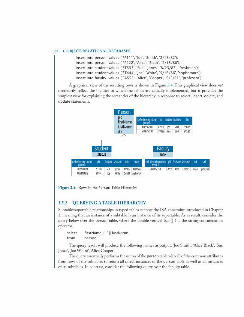
82 3. OBJECT-RELATIONAL DATABASES
insert into person values ('PP111', 'Joe', 'Smith', '2/18/82');insert into person values ('PP222', 'Alice', 'Black', '2/15/80');insert into student values ('ST333', 'Sue', 'Jones', '8/23/87', 'freshman');insert into student values ('ST444', 'Joe', 'White', '5/16/86', 'sophomore');insert into faculty values ('FA555', 'Alice', 'Cooper', '9/2/51', 'professor');
A graphical view of the resulting rows is shown in Figure 3.4. This graphical view does notnecessarily reflect the manner in which the tables are actually implemented, but it provides thesimplest view for explaining the semantics of the hierarchy in response to select, insert, delete, andupdate statements.
Person
Studentstatus
Facultyrank
pldfirstNamelastNamedob
(self-referencing column)person ID
pld firstName lastName dob
3987236790150986752134
PP111 JoeAlice
SmithBlack
2/18/822/15/80PP222
(self-referencing column)person ID
pld firstName lastName dob status
1022789902390554403216
ST333 JonesSueJoe White
8/23/875/16/86
freshmansophomoreST444
(self-referencing column)person ID
pld firstName lastName dob rank
76400123578 FA555 Alice Cooper 9/2/51 professor
Figure 3.4: Rows in the Person Table Hierarchy
3.5.2 QUERYING A TABLE HIERARCHYSubtable/supertable relationships in typed tables support the ISA constraint introduced in Chapter1, meaning that an instance of a subtable is an instance of its supertable. As as result, consider thequery below over the person table, where the double vertical bar (||) is the string concatenationoperator.
select firstName || ' ' || lastNamefrom person;
The query result will produce the following names as output: ‘Joe Smith’, ‘Alice Black’, ‘SueJones’, ‘Joe White’, ‘Alice Cooper’.
The query essentially performs the union of the person table with all of the common attributesfrom rows of the subtables to return all direct instances of the person table as well as all instancesof its subtables. In contrast, consider the following query over the faculty table.

3.5. A CLOSER LOOK AT TABLE HIERARCHIES 83
select firstName || ' ' || lastNamefrom faculty;
The only name returned from the query is ‘Alice Cooper’. Unless otherwise specified, a queryover any typed table will return the direct instances of the table as well as instances of its subtablesand not instances of its supertables. A similar query over the student table will return ‘Sue Jones’and ‘Joe White’.
To retrieve only the direct instances of a table, the only option can be used in the from clauseto constrain the query results. The following query will only return ‘Joe Smith’ and ‘Alice Black’ inthe query result.
select firstName || ' ' || lastNamefrom only (person);
3.5.3 DELETING ROWS FROM A TABLE HIERARCHYConsider the case of a delete statement expressed over the root of a table hierarchy. The followingstatement over the person table will delete any row from the table hierarchy with the first name of‘Alice’, even if the most specific type of the row is a student or a faculty. This behavior is as expectedaccording to the ISA constraint for class hierarchies since a student ISA person and a faculty ISAperson. In particular, the statement will delete the rows for ‘Alice Black’ and ‘Alice Cooper’.
delete from person where firstName = 'Alice';
Deleting a tuple from a subtable also implicitly deletes the tuple from its supertables. Forexample, since a student ISA person, the deletion of ‘Sue Jones’ from the student table will alsoresult in ‘Sue Jones’ no longer being visible from the person table (i.e., because the tuple no longerexists in the student table).
delete from student where firstName = 'Sue' and lastName = 'Jones';
As a result of the above delete statement, a query to return all rows of the person table will notinclude ‘Sue Jones’ since the row for ‘Sue Jones’ has been removed from the table hierarchy. Recallthat each row has a most specific type. Once the row is removed, it is considered to be removed fromthe entire table hierarchy.
It is possible to restrict the rows that are deleted using the only clause.The following statementwill delete rows from person with a first name of ‘Joe’ only if the person does not have a most specifictype of student or faculty. As a result of the statement, the row for ‘Joe Smith’ is the only row deleted.The row for ‘Joe White’ still remains in the table hierarchy.
delete from only (person) where firstName = 'Joe';
3.5.4 UPDATING ROWS IN A TABLE HIERARCHYThe update statement operates in a manner similar to the delete statement. For example, thefollowing statement will change the first name of each row in the person table and in any subtables

84 3. OBJECT-RELATIONAL DATABASES
of person. As a result, the name of ‘Sue Jones’ in the student table will be changed even though thequery is expressed over the person table.
update personset firstName = 'Suzy'where firstName = 'Sue';
To restrict an update operation to rows that do not appear in any subtables, the only clause isused. The query below will change the first name of Joe Smith in the person table and not the firstname of Joe White in the student table.
update only (person)set firstName = 'Joey'where firstName = 'Joe';
It is important to note that the condition in the where clause of an update statement alsoapplies to all rows that are in supertables of the table identified in the update statement. If the set
clause refers to attributes that do not appear in the supertable, then the set clause is ignored.
3.5.5 CHECKPOINT: TYPED TABLE HIERARCHIESStructured types together with typed tables can be used to provide the object-relational equivalentof classes in the object-oriented data model. Instances of typed tables have object identifiers that areknown as references, where references can be system generated, user-defined, or based on attributesof the table.The use of the under clause in structured types and their corresponding table definitionscan be used to form tables into hierarchies that support inheritance of state and behavior. Multipleinheritance is not supported in the formation of table hierarchies. Queries can be expressed overtable hierarchies to return all of the objects in a table, including objects in the subtables. Queries canalso be restricted to return only the direct instances of a table. As with object-oriented data models,overlapping subclasses, abstract classes, total specialization, and attributed-defined subclasses fromconceptual models are not directly supported by table hierarchies in the SQL standard. Programmersmust find creative ways to enforce such constraints over table hierarchies.
3.6 REFERENCE TYPESPrevious sections in this chapter have mentioned the use of the self-referencing column. Recall thatthe self-referencing column is the internal object identifier, or reference, to a row. This reference is adata type known as a reference type, or ref. The syntax for defining ref types is shown in Figure 3.5. Aref type is a valid SQL data type and can therefore be used to define the type of a column in a table,an attribute in a structured type definition, a variable, or a parameter. When used as an attribute ofa structured type in combination with the use of typed tables, reference types can be used to modelobject associations between typed tables that are based on object identity rather than on foreign keys.Reference types therefore provide a way of modeling object relationships as in the object-orienteddata model.

3.6. REFERENCE TYPES 85
<reference type> ::= ref (<referenced_type>) [<scope_clause>] [array [unsigned_integer]] [<reference_scope_check>]
/* [ ] part of syntax*/
<scope_clause> ::= scope <table_name>
<referenced_type>::= <user_defined_type_name>
<reference_scope_check> ::= references are [not] checked [on delete <action>]
Figure 3.5: Syntax for Defining Reference Types
To illustrate the use of reference types, consider again the School Database Enterprisein Figure 3.1. There is a 1:N relationship between CampusClub and Faculty, where a club has oneadvisor and a faculty member can advise many clubs. There is also a M:N relationship betweenCampusClub and Student, indicating that students are members of many clubs and clubs have manystudent members. The campusClubUdt type can be redefined to use reference types as a means fordefining relationships with faculty and student objects.
create type campusClubUdt as( cId varchar(10),
name varchar(50) not null,location locationUdt,phone varchar(12),advisor ref(facultyUdt), /* Reference to a faculty object */members ref(studentUdt) array[50]) /* References to student objects */instantiable not final ref is system generated;
create table campusClub of campusClubUdt( primary key (cId),
ref is campusClubId system generated);
The revised campusClubUdt illustrates the use of two different ref types, one to model asingle-valued relationship and another to model a multivalued relationship. The type of advisor isdefined to be ref(facultyUdt).This type definition indicates that the value to be stored in the advisor
attribute is the value of a self-referencing column from a typed table that is associated with thefacultyUdt type, thus storing an object reference to a row instead of a value-oriented foreign key asin traditional relational tables. The name of the self-referencing column of the faculty table can beused to assign a ref value to a column defined as a ref type. In the update statement below, personID
is the name of the self-referencing column from the definition of the faculty typed table (inheritedfrom the person typed table).

86 3. OBJECT-RELATIONAL DATABASES
update campusClubset advisor =( select personID
from personwhere firstName = 'Alice' and lastName = 'Cooper')
where name = 'Campus Computer Club';
The members attribute in campusClubUdt is defined to be an array of references to studentobjects,defined as ref(studentUdt) array[50], thus allowing typed tables to directly model multivaluedobject references. Arrays of references are generally manipulated and queried through the use of SQLroutines.
3.6.1 SCOPES AND REFERENCE CHECKINGSince a structured type can be used as the basis for creating several typed tables, a scope clause canbe used in the specification of a ref type to restrict reference values to those from a specific typedtable. The syntax for the scope clause is shown in Figure 3.5.
If the scope clause is omitted, then the reference value stored in the attribute can be a rowfrom any table having the specified type. If the scope clause is specified, then a reference scope checkcan also be specified. Specifying that references are checked indicates that dangling references (i.e.,invalid reference values) are not allowed. By default, references are not checked.The on delete clauseof the reference scope check syntax allows the user to specify the same referential actions as used withthe specification of referential integrity for foreign keys. In the example below, the advisor attributeis redefined to indicate that object references must be from the faculty table and that references arechecked for validity. The on delete clause indicates that deletion of a referenced faculty object willcause the advisor attribute to be set to null.
advisor ref(facultyUdt) scope facultyreferences are checked on delete set null;
Notice that the syntax in Figure 3.3 also supports the specification of table scopes and referencechecks during the creation of typed tables. The syntax is the same as that used in the specificationof structured types.
3.6.2 QUERYING REFERENCE TYPESWhen querying tables that contain columns with reference values, users are generally not interestedin seeing the reference value. The reference value is typically a system-generated value that is usefulfor establishing object relationships but has little meaning from the users point of view. Instead, thereference value is typically used to perform an implicit join as a means of accessing some attribute ofthe row that is being referenced.
The SQL standard supports the dereference operator, denoted as a right arrow, →, to traversethrough object references.The query below returns the name of the advisor of the Campus Computer

3.7. MAPPING TO THE SQL STANDARD OBJECT-RELATIONAL FEATURES 87
Club. The query is expressed over the campusClub table, but the value returned is from the faculty
table. The dereference operator is used to implicitly join the campusClub and faculty tables basedon the reference value. The dereference operator provides a more concise, object-oriented way oftraversing from one object to another than the use of explicit join conditions over relational tables.
select advisor → firstNamefrom campusClubwhere name = 'Campus Computer Club';
The SQL standard also provides a deref() function than can be used to return the entirestructured type that is associated with a reference value.The following query will return all instancesof the facultyUdt type for advisors of campus clubs that are located in the Brickyard Building. Theresult of the query is a table with one column of type facultyUdt. The resulting table can then bequeried to access any of the attributes of the advisors.
select deref (advisor)from campusClub cwhere c.location.bldg = 'Brickyard Building';
The use of reference types is an important feature for mapping object-oriented conceptualdesigns to an object-relational representation.The following section provides more specific examplesof the use of reference types in the mapping process.
3.7 MAPPING TO THE SQL STANDARDOBJECT-RELATIONAL FEATURES
This section describes how to map EER and UML conceptual designs to object-relational databasedesigns. The techniques presented in this section build on the conceptual-to-relational mappingtechniques that are summarized in Appendix A. The process of mapping classes, attributes, andassociations is presented in the context of the Abstract Enterprise from Figure 1.1 (EER version)and from Figure 1.2 (UML version). These concepts are combined with mapping techniques forclass hierarchies to present the complete object-relational representation of the School DatabaseEnterprise from Figure 3.1. The Hollywood Enterprise in Figure 1.25 (EER version) andin Figure 1.26 (UML version) will also be used to illustrate mapping techniques for categories. Asin Chapter 2, side-by-side EER and UML diagrams are used to illustrate the mappings. The readershould refer to Appendix A if necessary for a review of relational mapping issues in support of theobject-relational techniques described in this section.
3.7.1 CLASSES, ATTRIBUTES, AND ASSOCIATIONSThe general approach to mapping EER and UML conceptual diagrams to object-relational featuresis to translate each class in the conceptual design to a structured type with a corresponding typedtable and to represent associations between classes using reference types. Reference types can be

88 3. OBJECT-RELATIONAL DATABASES
combined with arrays to implement multivalued associations. Arrays and methods can also be usedto implement multivalued attributes and derived attributes, respectively. The following subsectionselaborate on the details of the mapping process.
3.7.1.1 Simple and Derived AttributesRecall the class A of Figure 1.3 that has simple attributes (keyOfA, attrOfA), a composite attribute(compositeOfA) and a derived attribute (derivedAttr). Using the object-relational features of theSQL standard, class A is mapped to a typed table a with a corresponding structured type aUdt.
create type aUdt as( keyOfA varchar(3),
attrOfA varchar(3),compositeOfA row(attrA1 varchar(3), attrA2 varchar(3), attrA3 varchar(3)))instantiable not final ref is system generatedmethod derivedAttr() returns varchar(3);
create table a of aUdt( primary key(keyOfA),
ref is aID system generated);
The simple attributes keyOfA and attrOfA are defined in the structured type as varchar, for simplicity.Since the SQL standard provides inherent support for complex types, the composite attribute ofA can be directly represented as either a row type or a structured type. For simplicity, a row typeis used in this example. Structured types are useful for representing composite attributes when thecomposite attribute must be used in multiple table or type definitions or when there is a need fordefining parameters or variables that correspond to the composite value. Structured types are alsouseful for representing composite values that require specific method definitions for manipulationof the composite value.
The derived attribute derivedAttr is defined as a method within the aUdt structured type.Recall that a constructor function as well as observor and mutator functions will also be generatedfor keyOfA, attrOfA, and compositeOfA. Constraints associated with the attributes of the class areexpressed in the typed table definition. The definition of a identifies keyOfA as the primary key ofthe typed table, in addition to the use of a system generated internal object identifier aID. Even withthe use of object identifiers, primary keys are still useful from an application-oriented point-of-view.
3.7.1.2 Multivalued AttributesThe class C of Figure 1.4 illustrates a multivalued attribute, named multiValuedAttr. In a purerelational representation, a multivalued attribute must be mapped to its own table, including the keyattribute of the class. Since the SQL standard supports arrays as a collection type, multiValuedAttr
can be directly represented as an attribute of the structured type cUdt for the typed table c, wherethe attribute is defined as an array of a specific data type (varchar in this case).

3.7. MAPPING TO THE SQL STANDARD OBJECT-RELATIONAL FEATURES 89
create type cUdt as( keyOfC varchar(3),
attrOfC varchar(3),multiValuedAttr varchar(3) array[10])instantiable not final ref is system generated;
create table c of cUdt . . .
3.7.1.3 Bidirectional Associations Without AttributesIn ODL as described in Chapter 2, bidirectional associations without attributes are mapped to arelationship with an inverse specification for both classes involved in the association. The object-relational features of the SQL standard do not support inverse specifications as in ODL,but referencetypes can be used on each side of the association to achieve an object-oriented approach to therepresentation of bidirectional associations. As an example, consider the 1:1 bc association betweenthe classes B and C as illustrated in Figure 1.8. Define a typed table b having a structured type bUdt
with an attribute named bTOc of type ref (cUdt). Also define a typed table c having a structured typecUdt with an attribute cTOb of type ref (bUdt).
create type bUdt as( . . .
bTOc ref(cUdt) scope c references are checked on delete no action,. . .)instantiable not final ref is system generated;
create type cUdt as(. . .
cTOb ref(bUdt) scope b references are checked on delete set null,. . .)instantiable not final ref is system generated;
create table b of bUdt . . . bTOc with options not null . . .
create table c of cUdt . . .
Note that this definition is a circular reference, which technically requires the use of an alter
type statement to add the definition of bToC to the bUdt type after the cUdt type is defined. Forconceptual presentation of the type definitions in this example and in other circular definitions inthe remainder of this chapter, the alter type statement is omitted.
Unlike the object-oriented data model which provides automatic support for inverse relation-ships, the user is responsible for maintaining the inverse relationship that exists between b and c.For example, if the attribute bTOc for a row bi in b is assigned the object reference for the row cj
in c, then the application must be designed to update the attribute cTOb of the row cj to the objectreference for the row bi . The inverse relationship can be maintained through the use of triggers orstored procedures.
The cardinality ratio constraints of the association are inherent in the specification of theassociation by defining the reference type on each side of the association as a single-valued attribute.

90 3. OBJECT-RELATIONAL DATABASES
For the bc association in Figure 1.8, the type of each association is a single object reference of thespecified structured type.The total participation of class B in the bc association is defined by using thenot null constraint in the typed table definition for b (note the different syntax for defining columnconstraints in typed tables as specified in Figure 3.3). In the object-oriented database mappingof Chapter 2, this constraint must be handled as part of the behavior of the object and is notdirectly supported by the database. The object-relational representation therefore provides moredirect database support for the enforcement of attribute constraints.
Each reference in the bc association is constrained to store object references from a specifictyped table using the scope clause. Even though object-relational implementations do not automat-ically maintain inverse relationships in bidirectional associations, the references are checked clausecan be used to enforce referential integrity. As a result, the bTOc and cTOb attributes will nevercontain reference values for rows that do not exist in the referenced tables. If the clause is omittedor if the specification is references are not checked, then the attribute values may contain danglingreference values. In addition, an on delete action can be specified. For the bTOc attribute, the deleteaction is no action since rows of b have required participation in the association. As a result, a rowin c cannot be deleted if it is related to a row in b since deleting a row in c may violate the totalparticipation constraint of b. In the opposite direction, the action is set null, indicating that if a rowin b is deleted, then the cTOb attribute can be set to null, thus reflecting the partial participation ofc in the association.
The mapping approach described above for a 1:1 association also applies to a bidirectionalassociation without attributes having 1:N or M:N cardinality ratios. The only difference is that thetype on the many side of the association is an array of reference types. To illustrate the mapping,consider an M:N association between the classes B and C (not represented in the Abstract Enter-prise). The bidirectional association is mapped to an object-relational schema using two separatearrays of reference types, where a row in b is related to potentially many object references to rows ofc and a row of c is related to potentially many object references to rows of b.
create type bUdt as( . . .
bTOMANYc ref(cUdt) scope c array[10] references are checkedon delete cascade,. . . )instantiable not final ref is system generated;
create type cUdt as(. . .
cTOMANYb ref(bUdt) scope b array[10] references are checkedon delete set null,. . . )instantiable not final ref is system generated;
create table b of bUdt . . .
create table c of cUdt . . .

3.7. MAPPING TO THE SQL STANDARD OBJECT-RELATIONAL FEATURES 91
The example below illustrates the mapping for a 1:N association between B and C, where arow of b is related to potentially many object references to rows of c but a row of c is related to atmost one object reference to a row of b.
create type bUdt as(. . .
bTOMANYc ref(cUdt) scope c array[10] references are checkedon delete cascade,. . . )instantiable not final ref is system generated;
create type cUdt as(. . .
cTOb ref(bUdt) scope b references are checked in delete set null,. . . )instantiable not final ref is system generated;
create table b of bUdt . . .
create table c of cUdt . . .
3.7.1.4 Bidirectional Associations With AttributesWhen binary associations have attributes, an association typed table must be introduced to representthe attributes of the association. The association table includes two attributes with reference types- one for the structured type of each typed table participating in the binary association. Considerthe M:N ab association between classes A and B that has a descriptive attribute attrOfAB, as shownin Figure 1.6. Figure 2.2 gives the UML diagram for the corresponding reified association. Anassociation table is defined as a typed table named ab with a structured type abUdt having theattribute attrOfAB and two reference type attributes: abTOa and abTOb. The reference type ofabTOa is ref(aUdt) having scope a, indicating the row of typed table a that is participating in therelationship instance. Similarly, the reference type of abTOb is ref(bUdt) having scope b, indicatingthe row of typed table b that is participating in the relationship instance. The definitions for thestructured types involved in the association include attributes with reference types to the structuredtype of the association table.
create type aUdt as(. . .
aTOab ref(abUdt) scope ab array[10] references are checked on delete set null,. . .)instantiable not final ref is system generated;
create type bUdt as(. . .
bTOab ref(abUdt) scope ab array[10] references are checked on delete set null,. . .)instantiable not final ref is system generated;

92 3. OBJECT-RELATIONAL DATABASES
create type abUdt as(. . .
attrOfAB varchar(3),abTOa ref(aUdt) scope a references are checked on delete cascade,abTOb ref(bUdt) scope b references are checked on delete cascade. . .)instantiable not final ref is system generated;
create table a of aUdt . . .
create table b of bUdt . . .
create table ab of abUdt . . .
The structured type aUdt contains the attribute aTOab having as its type ref(abUdt) array[10],since an object of type aUdt is related to potentially many objects of type bUdt through the abUdt
structured type of the ab association table (the number 10 in the array definition is arbitrary andcan be set to a number appropriate for the specific association). Similarly, the structured type bUdt
contains the attribute bTOab having as its type ref(abUdt) array[10], since an object of type bUdt
is related to potentially many objects of type aUdt through the abUdt structured type of the ab
association table. Since the participation of a in the association is required, the application will needto ensure that there is always at least one value in the aTOab array.
3.7.1.5 Recursive AssociationsThe mapping of recursive associations is similar to the mapping of non-recursive associations, ex-cept that the recursive association is relating the typed table to itself using a recursive reference tothe structured type of the typed table. In Figure 1.9, the class B has a recursive association bb. Astraightforward approach for mapping a recursive association is to use the role names of the associ-ation as the names of the reference attributes in the structured type. For example, the parent role ofthe bb association is of type ref(bUdt) having the child attribute as its implied inverse relationship.The child attribute is an array of references to bUdt, representing the children of the parent. As innon-recursive binary associations, the user is responsible in an object-relational implementation formaintaining the integrity of the relationship, although reference checks and delete actions can bespecified to support maintenance of the association.
create type bUdt as( . . .
parent ref(bUdt) scope b references are checked on delete set null,child ref(bUdt) scope b array[10] references are checked on delete set null,. . .)instantiable not final ref is system generated;
create table b of bUdt . . .

3.7. MAPPING TO THE SQL STANDARD OBJECT-RELATIONAL FEATURES 93
3.7.1.6 N-ary AssociationsThe mapping of N-ary associations is similar to the mapping of binary associations having descriptiveattributes.An association table is defined to represent the N-ary association, and there are N referenceattributes defined,one for the structured type of each typed table involved in the association.Consideras an example, the ternary relationship given in Figure 1.10. In this relationship, finance is theassociation table having the structured type financeUdt with reference attributes financedBank,financedCar, and financedPerson that, respectively, refer to the bank, car, and person involvedin the transaction. In the inverse direction, the structured types bankUdt, carUdt, and personUdt
define reference attributes that point back to the financeUdt structured type. The cardinality ofeach attribute indicates the number of times a row from the typed table can participate in a finance
association. The attributes in bankUdt and personUdt, for example, are defined as arrays, indicatingthat a bank can finance many cars and a person can buy many cars. The attribute in carUdt issingle-valued, indicating that a car can only be sold once.
create type financeUdt( . . .
financedBank ref(bankUdt) scope bankreferences are checked on delete cascade,
financedCar ref(carUdt) scope carreferences are checked on delete cascade,
financedPerson ref(personUdt) scope personreferences are checked on delete cascade,
. . .)instantiable not final ref is system generated;
create type bankUdt /* inverse of financedBank */( . . .
carsFinanced ref(financedUdt) scope finance array[10]references are checked on delete set null,
. . .)instantiable not final ref is system generated;
create type carUdt /* inverse of financedCar */( . . .
financedBy ref(financeUdt) scope financereferences are checked on delete set null,
. . .)instantiable not final ref is system generated;
create type personUdt /* inverse of financedPerson */( . . .
carsFinanced ref(financeUdt) scope finance array[10]references are checked on delete set null,
. . .)instantiable not final ref is system generated;

94 3. OBJECT-RELATIONAL DATABASES
create table finance of financeUdt . . .
create table bank of bankUdt . . .
create table car of carUdt . . .
create table person of personUdt . . .
3.7.1.7 Unidirectional AssociationsUML conceptual class diagrams have the ability to represent unidirectional associations throughnavigability. A unidirectional association stores the association in one direction. To specify a uni-directional association, define a reference attribute within the structured type of one side of theassociation. For example, the unidirectional association bc shown in Figure 1.12 is defined as areference attribute in the structured type bUdt having the type ref(cUdt). The inverse of the unidi-rectional association is derived by providing a method in cUdt to derive the bUdt reference to whichan instance of cUdt is related.
create type bUdt( . . .
bTOc ref(cUdt) scope c references are checked on delete no action,. . . )instantiable not final ref is system generated;
create type cUdt ( . . . )instantiable not final ref is system generatedmethod cTOb( ) return bUdt;
create table b of bUdt . . . bTOc with options not null . . .
create table c of cUdt . . .
3.7.1.8 Weak EntitiesA weak entity of an EER diagram is typically related to its identifying owner by a 1:N relationship.In Figure 1.13, the Weak class is related to its identifying owner class A by its identifying relationshipdependsOn. The candidate key of a weak entity is formed by the combination of the primary keyof its identifying owner and its own partial key, which uniquely identifies the weak object in thecontext of the identifying owner. In the UML diagram of Figure 1.13, dependsOn is represented asa qualified association based on the partialKey.
To map this type of association to an object-relational representation, create a typed table forthe weak entity with a composite key that includes the key of the typed table for the owner class.The structured type for the typed table of the weak class can also include a reference attribute to therow of the typed table that represents the owner class.
create type aUdt as( . . .
keyOfA varchar(3),linkToWeak ref(weakUdt) scope weak array[10]
references are checked on delete set null,

3.7. MAPPING TO THE SQL STANDARD OBJECT-RELATIONAL FEATURES 95
. . . )instantiable not final ref is system generated;
create type weakUdt as( . . .
partialKey varchar(3),keyOfA varchar(3),linkToOwner ref(aUdt) scope a references are checked on delete cascade,. . . )instantiable not final ref is system generated;
create table a of aUdt( primary key (keyOfA) . . . );create table weak of weakUdt( linkToOwner with options not null,
foreign key(partialKey) references a(keyOfA) on delete cascade,primary key(partialKey, keyOfA) . . . );
For the semantics expressed in Figure 1.13, the reference attribute linkToWeak defined in aUdt
represents the array of weakUdt objects associated with an instance of aUdt. The inverse associationdefined as linkToOwner in weakUdt links an instance of weakUdt to its identifying aUdt ownerinstance. The a typed table defines the attribute keyOfA as its primary key. In addition, the weak
typed table includes the key of the identifying owner (keyOfA) in combination with the partialKey
to create a composite key for the weak table.
3.7.1.9 Constraints on Classes, Attributes, and AssociationsWhen mapping the object-oriented conceptual data models to the relational data model, relevantimplementation-level constraints to consider for classes, attributes, and associations include the spec-ification of candidate keys, referential integrity, participation, and multiplicity constraints. Mappingto the object-relational features of the SQL standard can still make use of primary key and unique-ness constraints to specify candidate keys. The referential integrity constraint is also extended to thespecification of reference types to make sure that the value of a reference attribute refers to an objectidentifier in the referenced table. In addition, the scope clause can be used to restrict the reference tobe from a specific typed table. The reference type specification in the SQL standard also inherentlysupports simple cardinality constraints, where arrays can be used with reference types to representmultivalued associations. A total participation constraint is inherently supported by placing a not
null constraint on a reference attribute. When a total participation constraint is used together witha multivalued association, the application may need to ensure that an array of references alwayscontains at least one value. Specific upper and lower bounds in multivalued associations must alsobe enforced by the application. Such constraints can be coded into the behavioral aspects of thestructured type definition.
In comparison to object-oriented databases, the representation of bidirectional associations inan object-relational schema using references types does not automatically support the specification

96 3. OBJECT-RELATIONAL DATABASES
and maintenance of inverse relationships. The maintenance of inverse relationships must be codedinto the behavior of the application.
3.7.2 CHECKPOINT: OBJECT-RELATIONAL MAPPING OF CLASSES,ATTRIBUTES, AND ASSOCIATIONS
Table 3.2 summarizes the mapping of classes, attributes, and associations to the object-relationalfeatures of the SQL standard using names such as cUdt and sUdt to represent generic type defini-tions. The first column indicates the component being mapped. The second column indicates thecorresponding type to be defined in the schema. The third column gives either the type and tabledefinitions associated with the type or the attribute definition that is added to the definition of thetype to realize the component of the object model. The mapping summary assumes the use of bidi-rectional associations. Remember that structured types associated with typed tables must be definedas instantiable and as not final.The specification for generating object references must be consistentbetween the structured type and the typed table (e.g., system generated in both the structured typeand the corresponding typed table). Standard column and table constraints can be defined on theattributes of a structured type in the typed table definition.
Table 3.2: Summary of Object Relational Mapping Heuristics for Classes, Attributes,and Associations.
Component Type Object-Relational Definitionclass C cUdt create type cUdt as ( … );
create table c of cUdt ( … );single-valued attribute s of C cUdt s typeOfS
composite attribute s of C cUdt s row( …)
(implemented as a row type)composite attribute s of C sUdt create type sUdt as ( … );(implemented as a structured type) cUdt s sUdt
multivalued attribute m of C cUdt m typeOfM array[n]
binary association, no attributes c1Udt c1TOc2 ref(c2Udt) scope c2(1:1 shown) c2Udt c2TOc1 ref(c1Udt) scope c1binary association ac with c1Udt c1TOac ref(acUdt) scope ac array[n]
attributes (e.g., attrOfAc) c2Udt c2TOac ref(acUdt) scope ac array[n]
Use an association class (M:N shown) acUdt attrOfAC typeOfattrOfAC,
acTOc1 ref(c1Udt) scope c1,
acTOc2 ref(c2Udt) scope c2recursive association c cUdt parent ref(cUdt) scope c,
(1:N shown) child ref(cUdt) scope c array[n]
Figure 3.6 presents the complete object-relational schema for the unidirectional version ofthe Abstract Enterprise in Figure 1.12. The specification of the schema is more complex than

3.7. MAPPING TO THE SQL STANDARD OBJECT-RELATIONAL FEATURES 97
create type aUdt as( keyOfA varchar(3), attrOfA varchar(3), compositeOfA row (attrA1 varchar(3), attrA2 varchar(3), attrA3 varchar(3)), aTOab ref(abUdt) scope ab array[10] references are checked on delete set null, aTOb ref(bUdt) scope ab references are checked on delete cascade, attrOfBA varchar(3), linkToWeak ref(weakUdt) scope weak array[10] references are checked on delete set null) instantiable not final ref is system generated method derivedAttr() returns varchar(3);
create table a of aUdt( aTOb with options not null, aTOab with options not null, primary key(keyOfA), ref is alD system generated);
create type weakUdt as( partial Key varchar(3), keyOfA varchar(3), attrOfWk varchar(3), linkToOwner ref(aUdt) scope a references are checked on delete cascade) instantiable not final ref is system generated;
create table weak of weakUdt( linkToOwner with options not null, primary key(partialKey, keyOfA), foreign key(partialKey) references a(keyOfA) on delete cascade, ref is wID system generated);
create type bUdt as( keyOfB varchar(3), attrOfB varchar(3), parent ref(bUdt) scope b references are checked on delete set null, bTOab ref(abUdt) scope ab array[10] references are checked on delete set null, bTOc ref(cUdt) scope c references are checked on delete cascade) instantiable not final ref is system generated method bTOa() returns aUdt, method children() returns bUdt array[10];
create table b of bUdt( bTOc with options not null, primary key(keyOfB), ref is bID system generated);
Figure 3.6: The SQL Standard Object-Relational Schema of the Unidirectional Abstract Enter-prise (Continues.)

98 3. OBJECT-RELATIONAL DATABASES
create type abUdt as( attrOfAB varchar(3), abTOa ref(aUdt) scope a references are checked on delete cascade, abTOb ref(bUdt) scope b references are checked on delete cascade) instantiable not final ref is system generated;
create table ab of abUdt( abTOa with options not null, abTOb with options not null, ref is abID system generated);
create type cUdt as( keyOfC varchar(3), attrOfC varchar(3), multiValuedAttr varchar(3) array[10]) instantiable not final ref is system generated method cTOb() returns bUdt;
create table c of cUdt( primary key(keyOfC), ref is cID system generated);
Figure 3.6: (Continued.) The SQL Standard Object-Relational Schema of the Unidirectional Ab-stract Enterprise
the pure relational version in Figure A.2 of Appendix A. The object-relational version, however,supports the direct representation of multivalued attributes and the use of reference types togetherwith arrays to represent 1:1, 1:N, and M:N associations between classes, where associations are basedon object references rather than foreign keys. Arrays of references must be manipulated and queriedthrough the use of SQL routines. Unlike the object-oriented mapping in Chapter 2, the user mustmaintain inverse relationships. The unidirectional mapping in Figure 3.6, however, illustrates howunidirectional relationships can be used to directly represent the relationship in one direction andto derive the relationship in the opposite direction through the use of a method (see the methoddefinitions in cUdt and in bUdt that correspond to the inverse of each unidirectional relationship).
3.7.3 CLASS HIERARCHIESThe object-relational features of the SQL standard provide inherent support for the specificationof class hierarchies. The inheritance of state and behavior is supported by the under clause in thestructured type and typed table specifications. An example was provided in Section 3.3 using thePerson hierarchy from the School Database Enterprise.
The EER and UML conceptual data models both provide support for the specification ofspecialization constraints: disjoint versus overlapping specialization, and total or mandatory partici-

3.7. MAPPING TO THE SQL STANDARD OBJECT-RELATIONAL FEATURES 99
pation in the class specialization. The object-relational model of the SQL standard does not providefor an overlapping specialization of subclasses. Therefore, by default, a specialization in an object-relational schema is disjoint. As in most object-oriented database implementations, if an overlappingspecialization is required for the application, the programmer must simulate the inheritance for allbut one of the subtables by using an explicit reference from the overlapping subtables to the su-pertable and explicitly calling the methods of the supertable to which it is related. The object will,of course, have multiple identifiers, one for each typed table (simulating the overlapping subtables)to which it belongs, and inheritance from the supertable to the overlapping subtables will not beinherently supported. The implementation of the overlapping specialization constraint thereforerequires more coding effort on the part of the programmer to correctly represent the semantics ofan overlapping specialization. The relational mapping techniques described in Appendix A can beused to simulate overlapping specialization.
The total specialization constraint is supported in the SQL standard for hierarchies of struc-tured types but not for hierarchies of typed tables. In a structured type hierarchy, the supertype canbe defined as not instantiable, while the subtypes can be defined as instantiable. The supertypetherefore becomes an abstract type where the type can only be instantiated at the subtype level.But when structured types are used together with typed table hierarchies, structured types must bedefined as instantiable. The total specialization constraint must therefore be enforced through theapplication code by only allowing the insertion of objects at the subtable level.
The object-relational features of the SQL standard do not support the specification of sharedsubclasses from the EER model or the concept of interface classes from UML class diagrams.Attribute-defined subclasses from the EER model and discriminators from UML are also not in-herently supported. If such features are used in a conceptual model that must be mapped to anobject-relational implementation, the programmer must find creative solutions to the implementa-tion of such requirements.
3.7.4 CATEGORIESA category in the EER or the Xor constraint in UML can be represented by introducing a typedtable for the category. Attributes are introduced in the structured type of the category typed table torepresent the association to its related superclasses.
The standard example of a category that has been used in previous chapters is the partialSponsor category from the Hollywood Enterprise, where a Sponsor is either a Person or aCompany, but a Person or a Company is not required to be a Sponsor. A unidirectional referenceattribute is defined in the structured type sponsorUdt for each class participating in the category:personSponsor with a reference type of personUdt and companySponsor with a reference type ofcompanyUdt. Only one of the unidirectional attributes can have a value at any given time.The otherunidirectional attribute must always be null, since an instance of sponsorUdt cannot be related toboth a personUdt and a companyUdt. This category constraint must be implemented within thebehavior of sponsorUdt.

100 3. OBJECT-RELATIONAL DATABASES
create type personUdt as ( . . . )instantiable not final ref is system generated;
create type companyUdt as ( . . . )instantiable not final ref is system generated;
create type sponsorUdt as( . . .
personSponsor ref(personUdt), //Can also be implemented as bidirectionalcompanySponsor ref(companyUdt) //relationships for total categories.. . . )instantiable not final ref is system generated;
create table person of personUdt . . .
create table company of companyUdt . . .
create table sponsor of sponsorUdt . . .
When the category is partial, a unidirectional association is preferred. It is still possible to findout whether a person or company is a sponsor and to find the projects that they sponsor by navigatingthe unidirectional associations from the sponsor typed table. If the category is total, requiring thatevery person and every company must participate in the category, then the category associationscan be implemented using bidirectional relationships, where personUdt and companyUdt containreference attributes that point back to sponsorUdt.The use of bidirectional relationships provides anexplicit access path from person and company to the sponsor category table.The total categorizationconstraint can be enforced in the person and company tables by defining the reference attributeto sponsorUdt to be not null. Again, the person category table must still enforce the exclusive-orconstraint of the category.
3.8 CHECKPOINTFigure 3.7 presents the complete SQL schema for the School Database Enterprise in Fig-ure 3.1. The schema uses the object-relational features of the standard to represent hierarchies andobject associations. Whereas the clubs, advises, and chair associations from Figure 3.1 are imple-mented using bidirectional reference attributes between structured types, the associations for major
and worksIn are implemented as unidirectional reference attributes with methods in departmentUdt
to derive the inverse values. The mandatory participation constraint on the person hierarchy mustbe enforced through the application code that controls the insertion of rows into the student andfaculty tables (not allowing direct insertion into the person table).
3.9 ORACLE: OBJECT-RELATIONAL DATABASE MAPPINGSThis section presents an object-relational version of the School Database Enterprise imple-mented using Oracle 11g. The implementation illustrates the use of user-defined types, referencetypes, and typed tables, as well as Oracle’s support for collections in the form of variable-sized arrays

3.9. ORACLE: OBJECT-RELATIONAL DATABASE MAPPINGS 101
create type personUdt as( pld varchar(11), firstName varchar(20), lastName varchar(20), dob date) instantiable not final ref is system generated;
create type facultyUdt under personUdt as( rank varchar(10), advisorOf ref(campusClubUdt) scope campusClub array[5] references are checked on delete set null, worksln ref(departmentUdt) scope department references are checked on delete no action, chairOf ref(departmentUdt) scope department references are checked on delete set null) instantiable not final;
create type studentUdt under personUdt as( status varchar(10), memberOf ref(campusClubUdt) scope campusClub array[5] references are checked on delete set null, major ref(departmentUdt) scope department references are checked on delete no action) instantiable not final;
create table person of personUdt( primary key(pld), ref is personID system generated);create table faculty of facultyUdt under person;create table student of studentUdt under person;
create type departmentUdt as ( code varchar(3), name varchar(40), deptChair ref(facultyUdt) scope faculty references are checked on delete no action) instantiable not final ref is system generated method getStudents() returns studentUdt array[1000], method getFaculty() returns facultyUdt array[50];
Figure 3.7: The SQL Standard Object-Relational Schema of the School Database Enterprise.©ACM, 2003. This is a minor revision of the work published in “Using UML Class Diagrams for aComparative Analysis of Relational, Object-Oriented, and Object-Relational Database Mappings," byS. Urban and S. Dietrich in Proceedings of the 34th ACM SIGCSE Technical Symposium on Computer ScienceEducation, (2003) http://doi.acm.org/10.1145/620000.611923 (Continues.)
102 3. OBJECT-RELATIONAL DATABASES
create table department of departmentUdt( primary key (code), deptChair with options not null, ref is departmentID system generated);
create type locationUdt as( street varchar(30), bldg varchar(5), room varchar(5)) not final;
create type campusClubUdt as( cld varchar(10), name varchar(50), location locationUdt, phone varchar(12), advisor ref(facultyUdt) scope faculty references are checked on delete cascade, members ref(studentUdt) scope student array[50] references are checked on delete set null) instantiable not final ref is system generated;
create table campusClub of campusClubUdt ( primary key(cld), ref is campusClubID system generated);
Figure 3.7: (Continued.) The SQL Standard Object-Relational Schema of the School DatabaseEnterprise. ©ACM, 2003. This is a minor revision of the work published in “Using UML ClassDiagrams for a Comparative Analysis of Relational, Object-Oriented, and Object-Relational DatabaseMappings," by S. Urban and S. Dietrich in Proceedings of the 34th ACM SIGCSE Technical Symposium onComputer Science Education, (2003) http://doi.acm.org/10.1145/620000.611923
(varrays) and nested tables, which is a feature that is not supported by the SQL standard. Objecttype hierarchies and a feature known as substitutable tables are used as a means to support classhierarchies.
Figure 3.8 shows a modified UML diagram of the School Database Enterprise, withannotations that explain the manner in which relationships of the enterprise are mapped to theOracle object features. The Person, CampusClub, and Department classes are translated into objecttypes. The Student and Faculty classes are translated into subtypes under the type for the Person
class to form a type hierarchy. Tables are then created for the types associated with the Person,CampusClub, and Department classes, where the table for the Person class is a substitutable tablethat holds all objects from the person type hierarchy.
The clubs association is implemented as a bidirectional association, with a varray of referenceson one side of the association and a nested table of references on the other side of the association

3.9. ORACLE: OBJECT-RELATIONAL DATABASE MAPPINGS 103
for an object-oriented approach to the implementation of M:N associations. The getClubs methodhas been added to the Student class to provide a way to return the names of the clubs (rather thanthe references) in which a student participates. The 1:N advises association, also bidirectional, isimplemented as a varray in Faculty to store a collection of references to the campus clubs thata faculty member advises. The getClubsAdvised method has been added to Faculty to return thenames of the advised clubs. In CampusClub, an inverse reference attribute is used to point back to theadvisor of the club. The chair association is also bidirectional, implemented as a reference attributeon each side of the relationship. The majorsIn and worksIn associations are unidirectional, with areference attribute in Student and Faculty, respectively. The getStudents and getFaculty methodsin Department are used to derive the inverse of each association. All of the relevant type and tabledefinitions for the Oracle object-relational representation of Figure 3.8 appear in Figure 3.9.
3.9.1 OBJECT TYPES AND TYPE HIERARCHIESIn conformance with the SQL standard, Oracle supports the basic object-relational feature of objecttypes. An object type is a composite structure that can have a set of attributes and methods. Below isa simple example of a person_t object type definition for the Person class without methods. Noticethat the Oracle definition of an object type does not require the instantiation, finality, and referencegeneration clauses as in the SQL standard.
create or replace type person_t as object( pId varchar2(9),
firstName varchar2(20),lastName varchar2(20),dob date);
To assign values to an object type, a variable can be created having the type of the object type.The following example illustrates how to assign values into the attributes of the person_t object typein PL/SQL.
declarep person_t;begin
p.pId := 'PR123456789';p.firstName := 'Terrence';p.lastName := 'Grand';p.dob := '10-NOV-1975';
end;
Oracle does not support row types from the SQL standard. When an object type is usedas the attribute value of another object type, the attribute value is referred to as an embedded object.Embedded objects do not have object identifiers,but provide a way to define an attribute as containinga composite value. In the following example, the location attribute of the campusClub_t object typeis used as an embedded object.

104 3. OBJECT-RELATIONAL DATABASES
Person
StudentCampusClub
Department
Faculty* *
members memberOf* 0..1
advisorOf advisoradvisesclubs
*
major1
{disjoint, mandatory}
0..1
*
worksIn
chairOf
0..1deptChair
chair
students
majorsIn
dept
plddobfirstNamelastName
members implemented as a nested table in CampusClub
memberOf implemented as a varray in Student
advisorOf implemented as a varray in Faculty
cldname locationphone
The 1 side of all1:1 and 1:N associations are implemented as object references
statusgetClubs
codenamegetStudentsgetFaculty
rankgetClubsAdvised
Figure 3.8: UML for the Oracle Object-Relational Case Study of the School Database Enter-prise. ©ACM, 2003.This is a minor revision of the work published in “Using UML Class Diagrams fora Comparative Analysis of Relational, Object-Oriented, and Object-Relational Database Mappings," byS. Urban and S. Dietrich in Proceedings of the 34th ACM SIGCSE Technical Symposium on Computer ScienceEducation, (2003) http://doi.acm.org/10.1145/620000.611923
create or replace type location_t as object( street varchar2(30),
bldg varchar2(5),room varchar2(5));
create or replace type campusClub_t as object( cId number,
name varchar2(50),phone varchar2(25),location location_t,. . . );
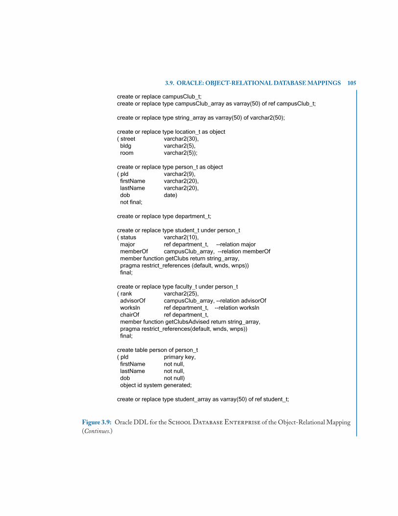
3.9. ORACLE: OBJECT-RELATIONAL DATABASE MAPPINGS 105
create or replace campusClub_t;create or replace type campusClub_array as varray(50) of ref campusClub_t;
create or replace type string_array as varray(50) of varchar2(50);
create or replace type location_t as object( street varchar2(30), bldg varchar2(5), room varchar2(5));
create or replace type person_t as object( pld varchar2(9), firstName varchar2(20), lastName varchar2(20), dob date) not final;
create or replace type department_t;
create or replace type student_t under person_t( status varchar2(10), major ref department_t, --relation major memberOf campusClub_array, --relation memberOf member function getClubs return string_array, pragma restrict_references (default, wnds, wnps)) final;
create or replace type faculty_t under person_t( rank varchar2(25), advisorOf campusClub_array, --relation advisorOf worksln ref department_t, --relation worksln chairOf ref department_t, member function getClubsAdvised return string_array, pragma restrict_references(default, wnds, wnps)) final;
create table person of person_t( pld primary key, firstName not null, lastName not null, dob not null) object id system generated;
create or replace type student_array as varray(50) of ref student_t;
Figure 3.9: Oracle DDL for the School Database Enterprise of the Object-Relational Mapping(Continues.)
106 3. OBJECT-RELATIONAL DATABASES
create or replace type faculty_array as varray(50) of ref faculty_t;
create or replace type department_t as object( code varchar2(3), name varchar2(40), deptChair ref faculty_t, member function getStudents return student_array, member function getFaculty return faculty_array, pragma restrict_references(default, wnds, wnps));
create table department of department_t( code primary key, name not null, constraint department_chair foreign key(deptChair) references person on delete set null) object id system generated;
create or replace type student_ntable as table of ref student_t;
create or replace type campusClub_t as object( cld number, name varchar2(50), phone varchar2(25), location location_t, advisor ref faculty_t, --relation advised by members student_ntable, --relation member of constraint club_advisor foreign key (advisor) references person on delete set null, member function isAssociatedMember (candidate_member in ref student_t) return boolean, member function isAssociatedAdvisor (candidate_advisor in ref faculty_t) return boolean, pragma restrict_references(default, wnds, wnps));
create table campusClub of campusClub_t( cld primary key, name not null) object id system generated nested table members store as club_members;
alter table club_members add( scope of (column_value) is person);
create unique index club_members_idx on club_members(nested_table_id, column_value);
Figure 3.9: (Continued.) Oracle DDL for the School Database Enterprise of the Object-Relational Mapping.

3.9. ORACLE: OBJECT-RELATIONAL DATABASE MAPPINGS 107
When an object type is used as the type of a column in a traditional relational table, the valueis referred to as a column object. Embedded and column objects are accessed and manipulated in thesame way as described in the SQL standard for structured types. For example, consider the followingtable definition with a column object loc.
create table courseOffering(code int, loc location_t);
Data can be inserted into the table using the type constructor for location_t.
insert into courseOffering values (123, location_t('Orange Mall', 'CPCOM', '207'));
Object type definitions may also contain method specifications. The methods of an objecttype are functions or procedures that model the behavior of objects. Recall that methods in the SQLstandard are limited to functions only. As in the SQL standard, the self parameter is an instance ofthe object type on which a method is invoked. The following example illustrates the PL/SQL codedefinition of the isAssociatedAdvisor function, where the declaration of the function is shown inthe campusClub_t object type definition in Figure 3.9.
create or replace type body campusClub_t is. . .
member function isAssociatedAdvisor (candidate_advisor in ref faculty_t)return boolean is
beginreturn (self.advisor = candidate_advisor);
end isAssociatedAdvisor;end;
The isAssociatedAdvisor function determines whether a faculty member is an advisor of a club.Methods are implemented in the object type body definition for campusClub_t.
The declaration of the isAssociatedAdvisor function as well as the isAssociatedMember
function in campusClub_t of Figure 3.9 is also accompanied by a pragma declaration. Pragmas arecompiler directives.Pragmas do not affect the meaning of a program.They simply convey informationto the compiler. Pragma restrict_references is used to control side effects in a function, asserting thata function does not read/write any database tables and/or package variables. The syntax is: pragma
restrict_references (function_name, option [, option]). The function name of default can be usedto specify that the pragma applies to all functions in the type definition. The pragma options are thefollowing:
wnds - Writes no database state (does not modify database tables).
rnds - Reads no database state (does not query database tables).
wnps - Writes no package state (does not change the values of package variables).
rnps - Reads no package state (does not reference the values of package variables).

108 3. OBJECT-RELATIONAL DATABASES
In addition to the methods explicitly defined in an object type definition, every object typehas a system-defined constructor method, which is a method that creates a new instance of an objecttype and sets up the values of its attributes. The name of the constructor method is the name of theobject type. Its parameters have the names and types of the object type’s attributes. The constructormethod is a function that returns an instance of an object type as its value. For example, the followinginvocation of the person_t constructor method returns an instance of the person_t object type withthe specified attribute values. Unlike the definition of constructor methods in the SQL standard,the built-in constructor for an object type in Oracle accepts parameter values for the attributes ofthe type.
person_t('PR123456789', 'Terrence', 'Grand', '10-NOV-1975')
As in the SQL standard, Oracle enhances object features by supporting type inheritance. Theuser can create an object type as a supertype and form a type hierarchy by defining one or moresubtypes of the supertype. As shown in Figure 3.9, student_t and faculty_t are defined as subtypesunder person_t. Objects of type student_t, for example, will then inherit the attributes of person_t
and also define additional attributes (status, major, and memberOf) and methods (getClubs) forobjects of type student_t. As a supertype, person_t must be defined as not final so that subtypes canbe defined. Unlike the SQL standard, a type at the bottom of the type hierarchy can be specified asfinal.
3.9.2 OBJECT TABLESAn object table is a table in which each row represents an object, where each object has a uniqueobject identifier (OID). Objects that occupy complete rows in object tables are called row objects.Oracle allows row objects to be referenced, meaning that other row objects or relational rows mayreference a row object using its OID.
The unique OID value can be specified using table constraints as either system-generated orbased on the row object’s primary key. The default OID value is system generated. Figure 3.9 showshow to create an object table based on an object type for the Person, CampusClub, and Department
classes in the School Database Enterprise, where the syntax is similar to that for definingobject tables in the SQL standard. For example, object table person is defined based on the objecttype person_t. The ref is clause of the SQL standard is replaced by the object id clause to specifyhow object identifiers are generated. In Figure 3.9, all of the table definitions indicate that objectidentifiers are system generated. As in the standard, table and column constraints can be defined inthe specification of the object table.
As a deviation from the SQL standard, object tables in Oracle cannot be formed into tablehierarchies. Instead, Oracle supports the concept of substitutable tables. A substitutable table is atable that is capable of storing multiple object types from a type hierarchy. A substitutable tabletherefore has the polymorphic capability to store an object of a supertype and any subtype that canbe substituted for the supertype. In Figure 3.9, the person table is a substitutable table since it isassociated with the supertype of a type hierarchy. The person table is capable of storing objects

3.9. ORACLE: OBJECT-RELATIONAL DATABASE MAPPINGS 109
of type person_t as well as objects of type student_t. Row objects are inserted as shown in thestatements below, where each insert statement indicates the specific type of the object and includesvalues for attributes of person_t as well as values for the attributes of the subtype.
insert into person_tablevalues (person_t('101','Sue','Jones','05/16/1955'));
insert into person_tablevalues (student_t('102','Jim','Duncan','03/12/1989','senior',get _dref('CSE'),null);
insert into person_tablevalues (faculty_t('103','Joe', 'Smith','10/21/1960','Professor',null,get_dref('CSE'),null);
The insert statements for objects of type student_t and faculty_t invoke the get_dref function,which is passed the name of a department and returns a reference to the associated department object.Reference types are addressed in the following subsection.
3.9.3 REFERENCE TYPESOracle supports reference types (refs) as defined in the SQL standard, where reference types canbe used to define object-to-object relationships. In Oracle, a ref is a logical pointer to a row object.For example, in Figure 3.9, the advisor attribute of the campusClub_t object type refers to theobject type faculty_t. Also in Figure 3.9, a ref type is used to model the major relationship betweenstudent_t and department_t.
3.9.3.1 Constraining Reference TypesA ref column or attribute can be constrained using a scope clause or a referential constraint clause.When a ref column is unconstrained, it may store object references to row objects contained in anyobject table of the corresponding object type. Unconstrained references may also lead to danglingreferences. Currently, Oracle does not permit storing object references that contain a primary-keybased object identifier in unconstrained ref columns.
A ref column may be constrained in Oracle with a referential constraint similar to the spec-ification for foreign keys. The deptChair column of the department table in Figure 3.9 illustratesthe use of the references clause to specify a column referential constraint on deptChair. The clausespecifies that a ref stored in a deptChair column must point to a valid row object in the person
object table. This clause also implicitly restricts the scope of deptChair to the person object table.A ref column may also be constrained by being scoped to a specific object table, using a scope
clause as defined in the standard. The scope constraint is different from the referential constraintbecause the scope constraint has no implications on the referenced object (i.e., deleting a referencedobject can still cause a dangling reference). The advisor column of the campusClub object table isconstrained in Figure 3.9 using a references clause. The following alter table statement illustrates

110 3. OBJECT-RELATIONAL DATABASES
the use of the scope clause to alternatively constrain the advisor column to refer to objects in theperson table.
alter table campusClub add (scope for (advisor) is person);
The unique and primary key constraints cannot be specified for ref columns. However, aunique index may be created on a scoped ref column to ensure the uniqueness of the ref values.
3.9.3.2 Using Reference TypesQueries involving objects make a distinction between row objects, refs, and object types. Oracleprovides three functions to support queries involving objects:
• ref() is a function that takes a row object as its argument and returns the ref to that object.
• value() is a function that takes a row object and returns the instance of the object type.
• deref() is a function that takes a ref to an object and returns the instance of the object type.
As an example, consider the campusClub_t object type and its corresponding campusClub
object table together with the following sequence of code:
declareclub_ref ref campusClub_t;club campusClub_t;club_adv faculty_t;
beginselect value(c), ref(c), deref(c.advisor) into club, club_ref, club_advfrom campusClub cwhere c.name='The Hiking Club';
end;
In a select statement such as the one shown in the above code sequence, the table alias (cin this case) always contains a row object. To see the values of the attributes of the row object asdefined in the object type, use value(c). To get the ref to the row object, use ref(c). To get values ofthe attributes of the object type associated with a ref, use the deref() function. The only differencebetween value and deref is the input to each function, where value takes a row object as input andderef takes a ref as input. In both cases, the output is the instance of the object type (i.e., a tuple ofattribute values) associated with the object.
After executing the above query, club will contain a campusClub_t object type instance,club_ref will contain the ref of the object, and club_adv will contain an instance of the faculty_t
object type. Recall that c.advisor is a ref to faculty_t. The deref function is therefore applied to aref value to return the object type instance of the ref.

3.9. ORACLE: OBJECT-RELATIONAL DATABASE MAPPINGS 111
Recall that the insert statements for the person table invoked the get_dref function to retrievethe ref to a specific department object. The get_dref function is shown below, where the select
statement retrieves a department object using the code attribute and returns the reference to theobject for assignment to an attribute that is defined to be of type ref department_t.
create or replace function get_dref(d_code in varchar2)return ref department_t isd_ref ref department_t;cursor cr is
select ref(d) from department d where d.code = d_code;begin
open cr; fetch cr into d_ref; close cr; return d_ref;end get_dref;
Reference types can also be used in queries to construct path expressions as in object-orienteddatabase queries.The query below returns a string value representing the name of the department inwhich the advisor of the Campus Computer Club works. The expression c.advisor.worksIn.name
is a path expression, representing implicit joins between the object tables involved.
select c.advisor.worksIn.namefrom campusClub cwhere c.name = 'Campus Computer Club';
3.9.4 QUERYING SUBSTITUTABLE TABLESSince a substitutable table contains a heterogeneous collection of objects from a type hierarchy,queries over the table may need to indicate the specific types of objects to be returned.The followingselect statement will return information about all objects in the person table:
select value(p)from person_table p;
To retrieve details only about objects that are subtypes of the declared type of the table, the is
of clause can be used. The query below will only return objects of type student_t from the person
table.
select value(p)from person_table pwhere value(p) is of (student_t);
The treat function can also used to treat a supertype instance as a subtype instance. Thisis especially useful for assigning a variable to a more specialized type in a hierarchy and accessing

112 3. OBJECT-RELATIONAL DATABASES
attributes or methods of a subtype. As an example, the following query creates a view of studentobjects. The is of clause is used in the where clause to indicate that the view should include objectsof type student_t. The treat function is then used in the select clause to access the attributes thatare specific to the student_t object type.
create or replace view student(pId, firstName, lastName, dob, status, major,memberOf) as
select pId, firstName, lastName, dob, treat(value(p) as student_t).status,treat(value(p) as student_t).major, treat(value(p) as student_t).memberOf
from person pwhere value(p) is of (student_t);
3.9.5 VARRAYS AND NESTED TABLES AS COLLECTIONSIn Oracle, variable-sized arrays (varrays) and nested tables can be used to represent the many sideof 1: N and M: N relationships.
3.9.5.1 VarraysOracle allows arrays to be of a variable size, thus the name varray. A maximum size must be specifiedwhen an attribute of type varray is defined. The size can, however, be changed at a later time. Todefine an attribute as a varray, a varray type definition must first be created. Creating a varray typedoes not allocate space but simply defines a data type that can be used as the data type of a column ofa relational table, an object type attribute, or the type of a PL/SQL variable, parameter, or functionreturn value. In Figure 3.9, the varray type definition of campusClub_array is used to model themany side of the advisorOf relationship between campusClub_t and faculty_t. Varray definitionsare also shown for student_array and faculty_array, which are used respectably as output in thegetStudents and getFaculty functions declared for the department_t object type.
3.9.5.2 Nested TablesWhereas a varray is an indexed collection of data elements of the same type, a nested table is anunordered set of data elements of the same data type. A nested table has a single column, where thetype of the column is a built-in type or an object type. If the column in a nested table is an objecttype, the table can also be viewed as a multi-column table, with a column for each attribute of theobject type. The use of DML statements on nested tables such as select, insert, and delete are thesame as with regular relational tables.
In a nested table, the order of the elements is not defined. Nested tables are stored in a storagetable with every element mapping to a row in the storage table. Figure 3.9 illustrates a nested tabletype definition for the student_ntable nested table. The contents of the nested table are of typeref student_t,. The type definition is used to define the members attribute in campusClub_t. Thestorage table of the members nested table, club_members, is specified in the campusClub table

3.9. ORACLE: OBJECT-RELATIONAL DATABASE MAPPINGS 113
definition. Whereas the programmer accesses the nested table using the name members, the nameclub_members is used internally by Oracle to access and manipulate the nested table.
Figure 3.9 also shows the use of the scope constraint on the storage table club_members ofthe members nested table. The constraint indicates that the values stored in the ref column mustbe references to row objects in the person table. A unique index is created on the storage tableclub_members using the nested_table_id and column_value columns to restrict the uniqueness ofthe ref values. The nested_table_id column is a pseudocolumn in nested tables that holds the rowidentifier of the storage table. The column_value column is a pseudocolumn that holds the contentsof the nested table (in this case, a ref of type student_t).
3.9.5.3 Comparison of Varrays and Nested TablesVarrays and nested tables are similar in that the data types of all elements in each collection must bethe same. But varrays and nested tables differ in the way they are internally managed by Oracle. Avarray has the following characteristics:
• A varray cannot be indexed.
• A varray declaration must specify the maximum number of objects to hold.
• A varray is dense in that all positions from the first to the last must be filled. Individual elementscannot be deleted from a varray to leave a null value in an array position.
• The elements of a varray are ordered.
• If the size of the varray is smaller than 4000 bytes, Oracle stores the varray in line; if it isgreater than 4000 bytes, Oracle stores it in a Binary Large Object (BLOB).
In comparison, nested tables have the following characteristics:
• A nested table is an unordered set of data elements, all of the same data type having a singlecolumn.
• The type of the column in the nested table is either a built-in type or an object type.
• If an object type is used as the type of the column, the table can be viewed as a multi-columntable, with a column for each attribute of the object.
• Nested tables are stored in a separate storage table and can be indexed for efficient access.
• Nested tables are sparse (i.e., individual elements can be deleted from a nested table).
The choice between a varray and a nested table depends on the nature of the values or objectsstored in the collection. If the number of objects in a multivalued attribute or relationship is large,then a nested table should be used instead of a varray. A varray is normally used when the number ofobjects contained in a multivalued attribute is small and does not change. Interested readers shouldconsult Oracle 11g documentation for further details about accessing and modifying varrays andnested tables.

114 3. OBJECT-RELATIONAL DATABASES
3.10 BIBLIOGRAPHIC REFERENCESIn response to the Object-Oriented Database System Manifesto prepared by researchers of object-oriented database technology [Atkinson et al., 1990], Michael Stonebraker led a group of researchersin relational database technology in the preparation of the Third Generation Database System Man-ifesto, a document that outlined the manner in which relational technology could be extended tosupport object-oriented features [Stonebraker et al., 1990]. Rowe and Stonebraker demonstrated thefeasibility of object-relational technology with the development of Postgres [Rowe and Stonebraker,1987], an object-relational version of Ingres [Held et al., 1975] (an early relational database proto-type and research tool). Additional sources of information about object-relational technology canbe found in [Brown, 2001, Date and Darwen, 1998, Stonebraker, 1995].
The most complete source on the object-relational features of the SQL standard is [Melton,2002], with additional information about arrays and row types in [Gulutzan and Pelzer, 1999,Melton and Simon, 2001]. The complete SQL standards documents can be ordered by contact-ing the American National Standards Institute or the International Standards Organization. Adescription of the object-relational features of Oracle 11g can be found in the Oracle DatabaseObject-Relational Developer’s Guide [Oracle, 2010].
The use of the School Database Enterprise for mapping to object-relational tech-nology was originally presented in [Urban et al., 2000], with additional mapping issues addressedin [Urban and Dietrich, 2003].

115
A P P E N D I X A
Mapping Object-OrientedConceptual Models to the
Relational Data ModelEER and UML diagrams are excellent tools for modeling a database enterprise at a conceptual level.The modeled data and constraints must be mapped to an implementation data model to realize thedatabase application.This appendix reviews the mapping of these object-oriented conceptual modelsto the relational data model. The mapping coverage emphasizes the importance of maintaining theconstraints in the relational data model that are inherent in the object-oriented conceptual models.
The Abstract Enterprise and the Hollywood Enterprise presented in Chapter 1form the basis of the mapping discussion. The presentation emphasizes the mapping review usingthe side-by-side EER and UML diagrams from that chapter.
A.1 NOTATION AND TERMINOLOGYThe mapping of a conceptual model to the relational data model requires using the SQL standardto define relational tables and views for data representation together with constraints that enforceapplication semantics. Tables and views are different forms of relations. The distinction is that atable is a relation that is explicitly stored in the database, while a view is a relation that is derivedusing a query specification.
When mapping an object-oriented conceptual model to a relational schema, some componentsof the conceptual model are mapped to tables while other components are mapped to views.The termextensional schema refers to the relations that are defined using the create table statement, whereasthe term intensional schema refers to the view definitions. For brevity of presentation, this appendixintroduces a notation to summarize the specification of the extensional schema. A table definition issummarized by giving the name of the table, listing the attribute names, underlining the attributesthat form a candidate key of the table and listing the table constraints. Consider as an example ofthe notation:
tableName(keyAttribute, attr1, attr2, foreignKeyAttr)foreign key (foreignKeyAttr) references primaryKeyTable(primaryKeyAttr)
This summary schema shows a table named tableName, having four attributes: keyAttribute,
attr1, attr2, and foreignKeyAttr. The keyAttribute is a candidate key for the table. The value of a

116 A. MAPPING OBJECT-ORIENTED CONCEPTUAL MODELS
candidate key in a table uniquely identifies a tuple in the table. The foreignKeyAttr is an attributethat references the value of a primary key in another table. Therefore, a referential integrity tableconstraint is listed as part of the summary definition to capture this constraint in the schema. Sincethere is only one candidate key for tableName, the candidate key keyAttribute is also the primarykey. An explicit primary key table constraint will be used only when a table has more than onecandidate key.
If there are multiple candidate keys for a table, each candidate key will be underlined. Forexample,
tableMultipleCandidateKeys(candidateKey1, anyAttr, candidateKey2)primary key candidateKey1
indicates that the table named tableMultipleCandidateKeys has two candidate keys: candidateKey1
and candidateKey2. Each candidate key uniquely identifies a tuple in the table.Therefore, an explicitprimary key table constraint indicates which candidate key is considered the primary key for uniquelyidentifying a row in the table.
If a table has a composite candidate key, then the line underscores all of the attributes that arepart of the candidate key. For example,
tableCompositeCandidateKey(partOfCandidateKey1, partOfCandidateKey2, anyAttr)
indicates that the table named tableCompositeCandidateKey has one candidate key that consistsof two attributes: partOfCandidateKey1 and partOfCandidateKey2. The value of both attributes isrequired to uniquely identify a tuple in the table.
In summary, this syntax for describing a table definition is an abbreviation and abstractionto facilitate the presentation of mapping object-oriented conceptual models to the relational datamodel. This summary syntax is only used for the extensional schema. The view definitions for theintensional schema consist of query definitions, which must be explicitly specified.
A.2 CLASSESThe first step in mapping a conceptual model to the relational data model involves the mapping ofclasses. This section covers classes that are not part of a class hierarchy, deferring the mapping ofclass hierarchies to a later section of the appendix.
Consider the class A, shown in Figure 1.3, that has simple attributes (keyOfA, attrOfA), acomposite attribute (compositeOfA) and a derived attribute (derivedAttr). Class A is mapped to atable that contains its simple attributes. Since the relational data model does not allow structuredtypes, the composite attribute (compositeOfA) cannot be directly included. However, the simplecomponents (attrA1, attrA2, attrA3) of the composite attribute are included in the table.
a(keyOfA, attrOfA, attrA1, attrA2, attrA3)
The table for A does not include the derived attribute for A. One alternative is to define a view for A,which retrieves the stored attributes and computes the value of the derived attribute (derivedAttr)

A.3. ASSOCIATIONS 117
in the view definition. Another alternative is to explicitly store the value of the derived attribute inthe table for A and update its value using triggers, when the value on which it depends changes:
a(keyOfA, attrOfA, attrA1, attrA2, attrA3, derivedAttr)
A classical example of a derived attribute is that of a person’s age, which is computed based on thecurrent date and the person’s birthdate.
The class C shown in Figure 1.4 has simple attributes (keyOfC, attrOfC) and a multivaluedattribute (multiValuedAttr).The class C is mapped to a table of the same name, containing its simpleattributes. Since the relational data model allows only simple types for attributes, the multivaluedattribute must be mapped to its own table along with the key of the class.The key of the correspondingtable (multiC) is a composite key consisting of the key of the class and the multivalued attribute.Note that a referential integrity constraint must hold between the foreign key and the primary keythat it references.
c(keyOfC, attrOfC)multiC(keyOfC, multiValuedAttr)
foreign key (keyOfC) references c(keyOfC)
A.3 ASSOCIATIONSThe associations of a UML class diagram and the relationships of an EER diagram provide im-portant semantics about the relationships that exist between the entities involved in an enterprisemodel. These semantics affect the mapping of the conceptual model to relational tables and also de-termine the constraints that must be expressed to enforce the intended meaning of the associations.This section presents relational mapping considerations for associations. Binary associations can bemapped using either a bidirectional or unidirectional approach. In a bidirectional mapping, the re-sulting relational tables can be used to traverse the association in either direction. In a unidirectionalassociation, the mapping only supports traversal of the association in one direction. Although theEER model does not make a distinction between the bidirectional and unidirectional mappings,UML diagrams use navigation to explicitly specify the unidirectional approach.
Mapping techniques must also consider recursive binary associations, n-ary associations, weakentities, class hierarchies, shared subclasses, and categories. All of these features are supported by theEER and the UML modeling techniques. In all cases, participation and multiplicity constraints playan important role in the specification of association constraints. The following sections elaborate onassociation mappings beginning with mapping techniques for bidirectional binary associations.
A.3.1 BIDIRECTIONAL BINARY ASSOCIATIONSUsing a bidirectional mapping approach, a binary association is mapped to a table, where the at-tributes of the table include the primary key attributes of the related classes and any descriptiveattributes of the association. Since the resulting table representing the binary association contains

118 A. MAPPING OBJECT-ORIENTED CONCEPTUAL MODELS
two foreign keys referencing the primary key attributes of the classes involved in the association,referential integrity constraints must be introduced for each foreign key. The key of the resultingtable depends on the multiplicity of the association and the semantics of the enterprise.
The ab association shown in Figure 1.6 represents an M:N relationship between classes Aand B. Following the mapping heuristic, the association is mapped to a table containing the key of A(keyOfA), the key of B (keyOfB), and the descriptive attribute of the relationship (attrOfAB). Since abis an M:N relationship, the key of the table ab is a composite key. If the semantics of the applicationallow multiple values of attrOfAB for a given (keyOfA, keyOfB) pair, then the key of the ab tableis a composite key consisting of the attributes (keyOfA, keyOfB, attrOfAB). If there is exactly onevalue of attrOfAB for a given (keyOfA, keyOfB) pair, then the primary key of the ab table is (keyOfA,keyOfB), as shown in the following schema.
a(keyOfA, attrOfA, attrA1, attrA2, attrA3)b(keyOfB, attrOfB)ab(keyOfA, keyOfB, attrOfAB)
foreign key (keyOfA) references a(keyOfA),foreign key (keyOfB) references b(keyOfB)
The ba association of Figure 1.7 is an example of a 1:N relationship between classes B andA. The mapping of the ba association results in a table named ba containing the attributes keyOfA,keyOfB, and attrOfBA. Since an A is related to exactly one B, the keyOfA forms the primary keyof the ba table. The keyOfA and keyOfB attributes are each foreign keys of the ba table. Since anA must be related to an instance of B, there is an additional constraint requiring that the keyOfBattribute is not null. This additional not null constraint is not needed on the table representing theab association, since the keyOfA and keyOfB attributes are part of the primary key. The value ofprimary key attributes cannot be null.
a(keyOfA, attrOfA, attrA1, attrA2, attrA3)b(keyOfB, attrOfB)ba(keyOfA, keyOfB, attrOfBA)
foreign key (keyOfA) references a(keyOfA),foreign key (keyOfB) references b(keyOfB),constraint notNullB not null (keyOfB)
The bc association shown in Figure 1.8 illustrates a 1:1 relationship between classes B and C.Since the BC association does not have any descriptive attributes, its corresponding bc table containsonly keyOfB and keyOfC attributes. Each attribute is a candidate key of the bc table based on the 1:1cardinality ratio, and each attribute is a foreign key. Since B has total participation in the association,indicating that an instance of B must be related to exactly one instance of C, the attribute keyOfB ischosen as the primary key of the bc table. Since keyOfC is a candidate key, additional table constraintsare specified to enforce the existence and uniqueness of the attribute.

A.3. ASSOCIATIONS 119
b(keyOfB, attrOfB)c(keyOfC, attrOfC)bc(keyOfB, keyOfC)
primary key (keyOfB),foreign key (keyOfB) references b(keyOfB),foreign key (keyOfC) references c(keyOfC),constraint notNullCandidateKey not null (keyOfC),constraint candidateKeyConstraint unique (keyOfC)
A.3.2 PARTICIPATION AND MULTIPLICITY CONSTRAINTSThe participation and multiplicity constraints of the advanced conceptual models provide semanticsregarding the participation of a class in an association. In the 1:1 bc association, shown in Figure 1.8,class B has total participation in the association, requiring the participation of an instance of classB in the bc association. In the EER diagram, the double line linking class B to the relationship bc
indicates total participation. In the UML diagram, the multiplicity of 1..1 on the bc associationindicates that an instance of B must be related to a minimum of one and maximum of one instanceof C.
In the definition of the bc table, the foreign key and not null constraints on the keyOfC requirethat a B appearing in the bc table is related to exactly one C. However, these constraints do not checkthat there is a tuple in the bc table for each tuple in the B table. A schema-level integrity constraintcan be used to verify the total participation constraint. For example, the assertion totalBinC verifiesthe total participation constraint of B in the bc association, checking that there does not exist a Bthat does not participate in the bc association. Similar schema-level constraints must be specified forthe total participation of A in the ab association of Figure 1.6, and the ba association of Figure 1.7.
create assertion totalBinBCcheck (not exists(select *from bwhere b.keyOfB not in
(select bc.keyOfBfrom bc)));
The capability to specify general schema-level constraints is a powerful tool. However, notall implementations of SQL allow for check constraints across multiple tables. An alternative ap-proach to constraint checking is the use of views to find integrity constraint violations. The viewnotTotalBinBC finds instances of B that do not participate in the bc association.
create view notTotalBinBC asselect *from b

120 A. MAPPING OBJECT-ORIENTED CONCEPTUAL MODELS
where b.keyOfB not in(select bc.keyOfBfrom bc);
The min..max multiplicities of UML diagrams and the (min, max) pairs of EER diagramsgive specific requirements on the minimum and maximum number of times that an instance of aclass participates in an association instance. Consider the abstract EER diagram of Figure A.1. The(2,4) annotating the edge between class D and the relationship de indicates that an instance of classD participates a minimum of 2 times and a maximum of 4 times in the relationship instance. Assumethat the class D is mapped to a relational table of the same name containing the primary key keyOfD,and the table de represents the relationship instance containing a composite primary key (keyOfD,
keyOfE). The view countDinDE counts the number of times an instance of D participates in the de
association. The second operand in the union is required to return a zero count when an instance ofD is not participating in the de association.
create view countDinDE(keyOfD, countInDE) as(select keyOfD, count(*)from degroup by keyOfD)union(select keyOfD, 0from dwhere d.keyOfD not in (select de.keyOfD from de));
The assertion DinDE verifies the multiplicity constraints using the defined countDinDE view.
create assertion DinDEcheck (not exists(select *from countDinDEwhere countInDE < 2 or countInDE > 4));
«persistent» «persistent»D
keyOfD
* 2..4 EkeyOfE
DkeyOfD keyOfE(0,N)(2,4)
Ede
EER UML
Figure A.1: EER and UML Diagrams Illustrating Minimum and Maximum Constraints

A.3. ASSOCIATIONS 121
A.3.3 RECURSIVE ASSOCIATIONSWhen a binary association relates a class to itself, the association is called a recursive association. Acanonical example of a recursive binary association is the employee supervisory relationship, sincean employee’s supervisor is an employee. A recursive association is mapped in the same manner asany other binary association. A table is created with the primary keys of both classes related by theassociation. Since the primary keys are the same in a recursive association, the names of the attributesin the table representing the association must be renamed to include the role name of the attribute.
As an example, consider the abstract recursive association given in Figure 1.9, which relatesthe class B to itself via the bb association. The role name parent is given to the one side of theassociation, and the child role name labels the many side. The table bb that corresponds to therecursive association contains the primary key of B (keyOfB) twice: childKeyOfB and parentKeyOfB.The primary key of the table bb corresponds to the child role in the association (childKeyOfB), sincea parent can have many children but a child has one parent.
b(keyOfB, attrOfB)bb(childKeyOfB, parentKeyOfB)
foreign key (childKeyOfB) references b(keyOfB),foreign key (parentKeyOfB) references b(keyOfB)
A.3.4 N-ARY ASSOCIATIONSThe most common form of an association is a binary association, which relates two entities. However,associations involving more than two entities are possible. The same mapping approach for binaryassociations is applicable for associations of degree higher than two. The attributes that form theprimary key of each entity involved in the association is included in the resulting table.Any descriptiveattributes of the association are also included.
Recall the non-binary finance relationship between Car, Person, and Bank shown in Fig-ure 1.10. The ternary finance relationship represents a car dealership application where a personbuys a car that is financed by a specific bank. The finance table representing the ternary asso-ciation includes the key attributes of all three entities involved in the relationship (inventoryId,pId, and bankId) and the descriptive attribute of the association (loanAmount). The cardinalityratios/multiplicities of the association indicate that the car’s inventoryId forms a key for the table,since a car can only be sold once from the dealer’s inventory.
finance(inventoryId, pId, bankId, loanAmount)foreign key (inventoryId) references car(inventoryId),foreign key (pId) references person(pId),foreign key (bankId) references bank(bankId)
A.3.5 NAVIGATION OF UNIDIRECTIONAL ASSOCIATIONSThe bidirectional approach to mapping binary associations presented in Section A.3.1 created atable to represent the relationship containing the primary key attributes of both classes involved in

122 A. MAPPING OBJECT-ORIENTED CONCEPTUAL MODELS
the association. The resulting table provides a mechanism to traverse the association given eitherof the primary keys of the objects involved in the association. This approach to mapping binaryassociations assumed that the association was bidirectional. UML diagrams support the concept ofnavigability that allows the designer to restrict the association to be unidirectional. A unidirectionalassociation indicates that the implementation of the association is only stored in one direction.
Although M:N associations are inherently bidirectional, 1:N and 1:1 associations can beunidirectional and have an alternative mapping approach that does not require creating anothertable for the association. The alternative mapping strategy stores the primary key of the one-side ofthe association and any descriptive attributes of the association itself in the table representing theclass on the other side of the association.
The UML diagram in Figure 1.12 represents a revision of the UML diagram of Figure 1.2,changing the 1:N ba association to be unidirectional from A to B and the 1:1 bc association to beunidirectional from B to C.
The alternative mapping of the 1:N ba association results in two tables instead of three. Sincean A is related to exactly one B, the primary key of the related B (keyOfB) and the descriptive attributeof the ba association (attrOfBA) are included in the table for A. Since A has total participation in theba association, the keyOfB attribute is constrained to be not null.
b(keyOfB, attrOfB)a(keyOfA, attrOfA, attrA1, attrA2, attrA3, keyOfB, attrOfBA)
foreign key (keyOfB) references b(keyOfB),constraint totalParticipationAinBA not null (keyOfB)
A comparison of the schema designs for the mapping of the 1:N ba association is warranted.Since A has total participation in the relationship, the mapping that includes the keyOfB and theattrOfBA in the a table is preferred for performance reasons. When retrieving a tuple from the a table,the information regarding its ba association is accessed at the same time. When the ba association isstored in its own table, the a table and the ba table must be joined to retrieve the same information.
Another performance advantage is realized during database inserts, updates or deletes. Whenthe ba association is stored as part of the table for A, the total participation constraint of A in theba association is verifiable using a table-level constraint specifying that the keyOfB attribute valuecannot be null. When the ba association is stored in its own table, a schema-level constraint isrequired to enforce the total participation. A table-level constraint is more efficient to enforce thana schema-level constraint.
Another point to notice is that the navigability of an association in the relational data modelis not truly affected by the alternative mapping approaches. In both designs, there is a table thatcontains the primary key attributes of the associated values. The navigability of associations on theresulting schema design is more evident in object-oriented and object-relational approaches.
The alternative unidirectional mapping of the 1:1 bc association also results in two tablesinstead of three. Since B has total participation in the association, the primary key attributes of C areincluded in the table for B.

A.3. ASSOCIATIONS 123
c(keyOfC, attrOfC)b(keyOfB, attrOfB, keyOfC)
primary key (keyOfB),foreign key (keyOfC) references c(keyOfC),constraint notNullCandidateKey not null (keyOfC),constraint candidateKeyConstraint unique (keyOfC)
The unidirectional mapping of the 1:1 bc association shares the same advantages as theunidirectional mapping of the 1:N ba association: the key of the related instance of C is automaticallyretrieved as part of the tuple for an instance of B, and the total participation of B in the bc associationis enforced using the not null table constraint. When neither class has total participation in a 1:1association, the bidirectional approach is preferred. Without the total participation constraint, thereis no clear choice for the direction of the unidirectional association, which results in null values forany instances that do not participate in the 1:1 association.
A.3.6 WEAK ENTITIES AND IDENTIFYING RELATIONSHIPSThe classes that have been mapped up to this point had a primary key, allowing the unique iden-tification of an instance across the entire database. Recall that a weak entity in the EER model isexistence dependent on its identifying owner to form a partial key that uniquely identifies the weakentity in the context of its owner. To create a unique identifier for the weak entity, the partial key iscombined with the primary key of its identifying owner. A weak entity has total participation in theidentifying relationship that links the weak entity to its identifying owner. Figure 1.13 shows theWeak entity of the Abstract Enterprise, having the identifying relationship dependsOn linkingto class A as its identifying owner.
The mapping of a weak entity creates a table for that entity with its attributes and the primarykey attributes of its identifying owner.The table weak has a composite primary key consisting of thekey of its identifying owner (keyOfA) and its partialKey. A referential integrity constraint verifiesthe validity of the key of the identifying owner.
a(keyOfA, attrOfA, attrA1, attrA2, attrA3)weak(keyOfA, partialKey, attrOfWeak)
foreign key (keyOfA) references a(keyOfA)
When mapping an EER diagram to a relational schema, identifying relationships are notexplicitly mapped to a relation since the semantics of the identifying relationship are captured inthe mapping of the weak entity itself. Consider as a counter-example the explicit mapping of thedependsOn identifying relationship to its own table. Following the mapping approach for binaryassociations, the dependsOn table would include the primary key attributes of the identifying owner(A) and the weak entity (Weak). The values of the keyOfA and identifyingKeyOfA attributes wouldhave to be the same. This resulting dependsOn table is redundant in the relational schema since theweak table already captures the identifying owner in the primary key.
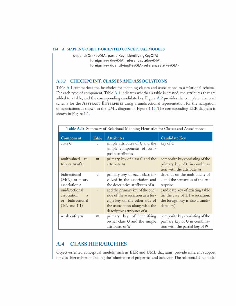
124 A. MAPPING OBJECT-ORIENTED CONCEPTUAL MODELS
dependsOn(keyOfA, partialKey, identifyingKeyOfA)foreign key (keyOfA) references a(keyOfA),foreign key (identifyingKeyOfA) references a(keyOfA)
A.3.7 CHECKPOINT: CLASSES AND ASSOCIATIONSTable A.1 summarizes the heuristics for mapping classes and associations to a relational schema.For each type of component, Table A.1 indicates whether a table is created, the attributes that areadded to a table, and the corresponding candidate key. Figure A.2 provides the complete relationalschema for the Abstract Enterprise using a unidirectional representation for the navigationof associations as shown in the UML diagram in Figure 1.12. The corresponding EER diagram isshown in Figure 1.1.
Table A.1: Summary of Relational Mapping Heuristics for Classes and Associations.
Component Table Attributes Candidate Keyclass C c simple attributes of C and the
simple components of com-posite attributes
key of C
multivalued at-tribute m of C
m primary key of class C and theattribute m
composite key consisting of theprimary key of C in combina-tion with the attribute m
bidirectional(M:N) or n-aryassociation a
a primary key of each class in-volved in the association andthe descriptive attributes of a
depends on the multiplicity ofa and the semantics of the en-terprise
unidirectionalassociation a
or bidirectional(1:N and 1:1)
– add the primary key of the one-side of the association as a for-eign key on the other side ofthe association along with thedescriptive attributes of a
candidate key of existing table(in the case of 1:1 association,the foreign key is also a candi-date key)
weak entity W w primary key of identifyingowner class O and the simpleattributes of W
composite key consisting of theprimary key of O in combina-tion with the partial key of W
A.4 CLASS HIERARCHIESObject-oriented conceptual models, such as EER and UML diagrams, provide inherent supportfor class hierarchies, including the inheritance of properties and behavior. The relational data model

A.4. CLASS HIERARCHIES 125
c(keyOfC, attrOfC)multiC(keyOfC, multiValuedAttr) foreign key(keyOfC) references c(keyOfC)b(keyOfB, attrOfB, keyOfC, parentKeyOfB) primary key (keyOfB), foreign key (keyOfC) references c(keyOfC) constraint notNullCandidateKey not null (keyOfC), constraint candidateKeyConstraint unique (keyOfC) /* alter table must be used to establish this recursive reference */ foreign key (parentKeyOfB) references b(keyOfB)a(keyOfA, attrOfA, attrOfA, attrA1, attrA2, attrA3, keyOfB, attrOfBA) foreign key (keyOfB) references b (keyOfB), constraint totalParticipation not null (keyOfB)ab(keyOfA, keyOfB, attrOfAB) foreign key (keyOfA) references a(keyOfA) foreign key (keyOfB) references b(keyOfB)weak(keyOfA, partialKey, attrOfWk) foreign key (key OfA) references a(keyOfA)
Figure A.2: Relational Schema of Abstract Enterprise using Unidirectional Navigability
provides the concept of a table,which does not inherently support class hierarchies.However, throughthe use of both the extensional and intensional schemas of the relational data model, class hierarchiescan be supported. There are three main approaches for mapping class hierarchies to tables:
1. Creating a table for each class,
2. Creating a table for subclasses only, and
3. Flattening the hierarchy.
The relational schema must represent both the specialized and inherited properties of a class. Foreach approach, a class C is realized by a relation of the same name, where a relation is either a storedtable or a view. Therefore, the relational schema consists of a specification of the extensional schemaof stored tables, the intensional schema of views, and the constraints that hold on the relations. Thename of a table that is created to assist with the definition of a class will use a suffix to differentiate itfrom the relation for the class.This discussion uses the Hollywood Enterprise (see Figures 1.25and 1.26) as examples of the class hierarchies for the alternative mapping approaches. Section A.4.4discusses support for specialization constraints.
A.4.1 CREATING A TABLE FOR EACH CLASSOne mapping approach for class hierarchies creates a table for each class in the class hierarchy,including superclasses and subclasses. The table for the superclass contains its attributes. The at-tributes of the table defined for the subclass include the primary key attributes of its superclass and
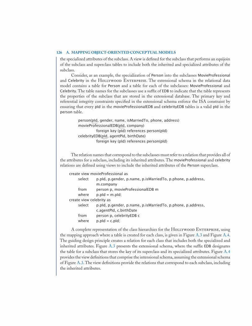
126 A. MAPPING OBJECT-ORIENTED CONCEPTUAL MODELS
the specialized attributes of the subclass. A view is defined for the subclass that performs an equijoinof the subclass and superclass tables to include both the inherited and specialized attributes of thesubclass.
Consider, as an example, the specialization of Person into the subclasses MovieProfessionaland Celebrity in the Hollywood Enterprise. The extensional schema in the relational datamodel contains a table for Person and a table for each of the subclasses: MovieProfessional andCelebrity. The table names for the subclasses use a suffix of EDB to indicate that the table representsthe properties of the subclass that are stored in the extensional database. The primary key andreferential integrity constraints specified in the extensional schema enforce the ISA constraint byensuring that every pId in the movieProfessionalEDB and celebrityEDB tables is a valid pId in theperson table.
person(pId, gender, name, isMarriedTo, phone, address)movieProfessionalEDB(pId, company)
foreign key (pId) references person(pId)celebrityEDB(pId, agentPId, birthDate)
foreign key (pId) references person(pId)
The relation names that correspond to the subclasses must refer to a relation that provides all ofthe attributes for a subclass, including its inherited attributes. The movieProfessional and celebrityrelations are defined using views to include the inherited attributes of the Person superclass.
create view movieProfessional asselect p.pId, p.gender, p.name, p.isMarriedTo, p.phone, p.address,
m.companyfrom person p, movieProfessionalEDB mwhere p.pId = m.pId;
create view celebrity asselect p.pId, p.gender, p.name, p.isMarriedTo, p.phone, p.address,
c.agentPId, c.birthDatefrom person p, celebrityEDB cwhere p.pId = c.pId;
A complete representation of the class hierarchies for the Hollywood Enterprise, usingthe mapping approach where a table is created for each class, is given in Figure A.3 and Figure A.4.The guiding design principle creates a relation for each class that includes both the specialized andinherited attributes. Figure A.3 presents the extensional schema, where the suffix EDB designatesthe table for a subclass that stores the key of its superclass and its specialized attributes. Figure A.4provides the view definitions that comprise the intensional schema, assuming the extensional schemaof Figure A.3. The view definitions provide the relations that correspond to each subclass, includingthe inherited attributes.

A.4. CLASS HIERARCHIES 127
person(pId, gender, name, isMarriedTo, phone, address)movieProfessionalEDB(pId, company)
foreign key (pId) references person(pId)criticEDB(pId, popularity)
foreign key (pId) references movieProfessionalEDB(pId)agentEDB(pId, agentFee)
foreign key (pId) references movieProfessionalEDB(pId)celebrityEDB(pId, agentpId, birthDate)
foreign key (pId) references person(pId)foreign key (agentpId) references agentEDB(pId)
movieStarEDB(pId, movieType)foreign key (pId) references celebrityEDB(pId)
modelEDB(pId, preferences)foreign key (pId) references celebrityEDB(pId)
project(projectId, cost, type, location)filmProjectEDB(projectId, title)
foreign key (projectId) references project(projectId)modelingProjectEDB(projectId, description)
foreign key (projectId) references project(projectId)actsIn(movieStarPId, filmProjectId)
foreign key (movieStarPId) references movieStarEDB(pId)foreign key (filmProjectId)references filmProjectEDB(projectId)
modelsIn(modelPId, modelingProjectId, paid)foreign key (modelPId) references modelEDB(pId)foreign key (modelingProjectId)references modelingProjectEDB(projectId)
Figure A.3: Extensional Schema for Class Hierarchies of the Hollywood Enterprise
A.4.2 CREATING A TABLE FOR SUBCLASSES ONLYAnother approach to mapping a class hierarchy to a relational schema creates a table for each subclassin the class hierarchy. In this approach, the table for each subclass includes both the specialized andinherited attributes. The relation for a superclass is defined using a view as a generalization of itssubclasses.The view inherently supports the ISA constraint, requiring that the subclass is a superclass.
Consider the specialization of Project into a FilmProject or ModelingProject. Since the tablefor the subclass includes all of the attributes for the subclass, including the inherited ones, the namesof the tables for the subclasses are filmProject and modelingProject.
filmProject(projectId, title, cost, type, location)

128 A. MAPPING OBJECT-ORIENTED CONCEPTUAL MODELS
create view movieProfessional asselect p.pId, p.gender, p.name, p.isMarriedTo, p.phone, p.address,
m.companyfrom person p natural join movieProfessionalEDB m;
create view critic asselect m.pId, m.gender, m.name, m.isMarriedTo, m.phone, m.address,
m.company, c.popularityfrom movieProfessional m natural join criticEDB c;
create view agent asselect m.pId, m.gender, m.name, m.isMarriedTo, m.phone, m.address,
m.company, a.agentFeefrom movieProfessional m natural join agentEDB a;
create view celebrity asselect p.pId, p.gender, p.name, p.isMarriedTo, p.phone, p.address,
c.agent, c.birthDatefrom person p natural join celebrityEDB c;
create view filmProject asselect p.projectId, p.location, p.cost, p.type, f.titlefrom project p natural join filmProjectEDB fwhere p.type = 'F';
create view modelingProject asselect p.projectId, p.location, p.cost, p.type, m.descriptionfrom project p natural join modelingProjectEDB mwhere p.type = 'M';
Figure A.4: Intensional Schema for Class Hierarchies of the Hollywood Enterprise
modelingProject(projectId, description, cost, type, location)
The relation for the Project superclass is defined by a view that is a union of the inheritedattributes from the filmProject and modelingProject tables. Therefore, the ISA constraint of thehierarchy, indicating that a FilmProject is a Project and a ModelingProject is a Project, is inherentlysupported by the intensional schema.
create view project asselect projectId, cost, type, locationfrom filmProjectunionselect projectId, cost, type, locationfrom modelingProject;
In mapping a class hierarchy via the approach in which a table is created for subclasses only,there are several issues to consider. One issue is that this mapping approach cannot support a partial
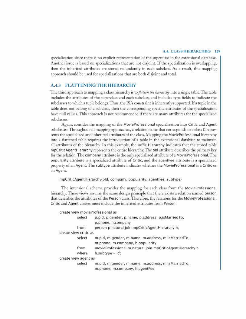
A.4. CLASS HIERARCHIES 129
specialization since there is no explicit representation of the superclass in the extensional database.Another issue is based on specializations that are not disjoint. If the specialization is overlapping,then the inherited attributes are stored redundantly in each subclass. As a result, this mappingapproach should be used for specializations that are both disjoint and total.
A.4.3 FLATTENING THE HIERARCHYThe third approach to mapping a class hierarchy is to flatten the hierarchy into a single table.The tableincludes the attributes of the superclass and each subclass, and includes type fields to indicate thesubclasses to which a tuple belongs.Thus, the ISA constraint is inherently supported. If a tuple in thetable does not belong to a subclass, then the corresponding specific attributes of the specializationhave null values. This approach is not recommended if there are many attributes for the specializedsubclasses.
Again, consider the mapping of the MovieProfessional specialization into Critic and Agentsubclasses. Throughout all mapping approaches, a relation name that corresponds to a class C repre-sents the specialized and inherited attributes of the class. Mapping the MovieProfessional hierarchyinto a flattened table requires the introduction of a table in the extensional database to maintainall attributes of the hierarchy. In this example, the suffix Hierarchy indicates that the stored tablempCriticAgentHierarchy represents the entire hierarchy.The pId attribute describes the primary keyfor the relation. The company attribute is the only specialized attribute of a MovieProfessional. Thepopularity attribute is a specialized attribute of Critic, and the agentFee attribute is a specializedproperty of an Agent. The subtype attribute indicates whether the MovieProfessional is a Critic oran Agent.
mpCriticAgentHierarchy(pId, company, popularity, agentFee, subtype)
The intensional schema provides the mapping for each class from the MovieProfessionalhierarchy. These views assume the same design principle that there exists a relation named personthat describes the attributes of the Person class. Therefore, the relations for the MovieProfessional,Critic and Agent classes must include the inherited attributes from Person.
create view movieProfessional asselect p.pId, p.gender, p.name, p.address, p.isMarriedTo,
p.phone, h.companyfrom person p natural join mpCriticAgentHierarchy h;
create view critic asselect m.pId, m.gender, m.name, m.address, m.isMarriedTo,
m.phone, m.company, h.popularityfrom movieProfessional m natural join mpCriticAgentHierarchy hwhere h.subtype = 'c';
create view agent asselect m.pId, m.gender, m.name, m.address, m.isMarriedTo,
m.phone, m.company, h.agentFee

130 A. MAPPING OBJECT-ORIENTED CONCEPTUAL MODELS
from movieProfessional m natural join mpCriticAgentHierarchy hwhere h.subtype = 'a';
Since the specialization of MovieProfessional into the Critic and Agent subclasses is disjoint,the specification of the corresponding subclasses uses a single type indicator (subtype). Multiple typeindicators can be used to specify overlapping subclasses. Consider the Celebrity specialization intothe overlapping subclasses of MovieStar and Model. Again, the suffix Hierarchy is appended to thetable name, representing that the celebrityHierarchy table is a flattening of the Celebrity hierarchy.The pId attribute forms the primary key of the resulting table.The birthDate and agentPId attributesare the specialized properties for a Celebrity. A MovieStar has an additional attribute for movieType,and a Model has an additional attribute for preferences.The Boolean attributes movieStar and modelindicate membership of the Celebrity in the corresponding subclass.
celebrityHierarchy(pId, birthDate, agentPId, movieStar, movieType, model, preferences)
The intensional schema defines relations for Celebrity, MovieStar and Model, assuming anexisting person relation that describes the attributes of the Person class. Since Celebrity is a subclassof Person and the MovieStar and Model are subclasses of Celebrity, they all inherit the attributes ofPerson.
create view celebrity asselect p.pId, p.gender, p.name, p.address, p.isMarriedTo, p.phone,
h.birthDate, h.agentPIdfrom person p natural join celebrityHierarchy h;
create view movieStar asselect c.pId, c.gender, c.name, c.address, c.isMarriedTo, c.phone,
c.birthDate, c.agentPId, h.movieTypefrom celebrity c natural join celebrityHierarchy hwhere h.movieStar;
create view model asselect c.pId, c.gender, c.name, c.address, c.isMarriedTo, c.phone,
c.birthDate, c.agentPId, h.preferencesfrom celebrity c natural join celebrityHierarchy hwhere h.model;
Attribute-defined subclasses are inherently supported using a single type indicator when flat-tening the hierarchy. Consider again the attribute-defined specialization of Project into a FilmProjector a ModelingProject. When the hierarchy is flattened, the extensional schema consists of one tablenamed projectHierarchy. Again, the Hierarchy suffix indicates that this table represents the flattenedhierarchy and not the Project class itself. All projects have the attributes projectId, location, cost,and type, where the type field indicates the type of the project. A FilmProject has a specializedattribute title, and the attribute description is a specialized attribute of ModelingProject.
projectHierarchy(projectId, location, cost, type, title, description)

A.4. CLASS HIERARCHIES 131
The intensional schema provides a relation for each class (Project, FilmProject and Model-ingProject) in the hierarchy using a view definition to provide the appropriate attributes of eachclass.
create view project asselect h.projectId, h.location, h.cost, h.typefrom projectHierarchy h;
create view filmProject asselect h.projectId, h.location, h.cost, h.type, h.titlefrom projectHierarchy hwhere h.type = 'F';
create view modelingProject asselect h.projectId, h.location, h.cost, h.type, h.descriptionfrom projectHierarchy hwhere h.type = 'M';
A.4.4 SPECIALIZATION CONSTRAINTSAs illustrated in Chapter 1, EER and UML diagrams provide inherent support for several special-ization constraints: disjoint, completeness, and attribute-defined. The disjoint constraint specifieswhether the subclasses in the resulting specialization are disjoint or overlapping. The completenessconstraint indicates whether the specialization is total or partial. A total specialization requires thatthe superclass must participate in the specialization into one of its subclasses. The attribute-definedspecialization constraint requires that the value of an attribute on which the specialization is definedis of the appropriate value for the subclass. These specialization constraints are not inherently sup-ported by the relational model but can be specified using schema-level integrity constraints. Thisexposition leverages the guiding principle in the design of the relational schema that realizes a class C
by a relation of the same name. Whether a relation is defined as a stored table or a view is transparentin the constraint specifications.
Consider the specification of the disjoint constraint disjointPersonSpecialization assertingthe disjoint specialization of Person into MovieProfessional and Celebrity. The disjoint constraintis violated if the pId of a Person represents both a MovieProfessional and a Celebrity.
create assertion disjointPersonSpecialization ascheck (not exists(select *from person pwhere p.pId in (select m.pId from movieProfessional m) and
p.pId in (select c.pId from celebrity c)));
In the Hollywood Enterprise, a MovieProfessional has a total specialization into a Criticor Agent, requiring that a MovieProfessional is either a Critic or an Agent. The total specialization

132 A. MAPPING OBJECT-ORIENTED CONCEPTUAL MODELS
constraint is violated if the pId of a MovieProfessional does not appear in the relations for Critic orAgent.
create assertion totalMovieProfessionalSpecialization ascheck (not exists(select *from movieProfessional mwhere m.pId not in
(select c.pId from critic c union select a.pId from agent a)));
The attribute-defined specialization constraint requires that the value of the attribute type ofa Project is either 'F' for a FilmProject or 'M' for a ModelingProject.
create assertion attrDefinedFilmProjectSpecialization ascheck (not exists(select *from project pwhere (p.projectId in (select f.projectId from filmProject f) and
p.type <> 'F') or(p.projectId not in (select f.projectId from filmProject f) andp.type = 'F')));
The attribute-defined specialization constraint is violated if the projectId attribute is consid-ered a FilmProject and the type attribute is not 'F' or if the type attribute is 'F' and the projectId
attribute does not represent a FilmProject. A companion constraint must also be included to verifythe value of the type attribute for a ModelingProject.
A summary of the specialization constraints in the alternative mapping approaches for map-ping class hierarchies is given in Table A.2. A checkmark indicates that the mapping approach cansatisfy the constraint, whereas an X indicates that the mapping approach should not be used for theindicated specialization constraint. A comment in parentheses provides a brief indication of how theapproach supports or fails to support the specialization constraint. A summary of the specializationconstraints supported by each approach as indicated in Table A.2 follows:
• Creating a table for each classThis mapping approach allows for the support of disjoint or overlapping specializations, totalor partial specializations, and attribute-defined specializations.
• Creating a table for subclasses onlyThis approach supports disjoint and total specializations, which includes attribute-definedspecializations. Overlapping specializations would result in redundancy of the inherited at-tributes of the superclass, which are stored in the table for each subclass. A partial specializationis not supported because the superclass is represented as a union of the inherited attributesstored in the tables for the subclasses.

A.5. SHARED SUBCLASSES 133
• Flattening the hierarchyThis mapping design also allows for the support of disjoint or overlapping specializations,total or partial specializations, and attribute-defined specializations. A single type indicatorrepresents a disjoint specialization since the attribute is single-valued. Overlapping special-izations are represented using multiple type indicators. Partial specializations are allowed. Ifthe superclass does not belong to a subclass, then the values of all of the specialized attributeswould be null.
Table A.2: Summary of Support for Specialization Constraints for Mapping ClassHierarchies.
Mapping Disjoint Completeness Attribute-Approach Constraint Constraint defined
Disjoint Overlapping Total Partial
Table foreach class
Table for × ×each subclass (redundancy) (no superclass)
Flatteningthe (single type (multiple type (null values)
hierarchy indicator) indicators)
A.4.5 CHECKPOINT: CLASS HIERARCHIESTable A.3 provides a summary of the approaches for mapping class hierarchies using the simple,abstract hierarchy shown in Figure A.5, consisting of a superclass S and two subclasses S1 and S2.The extensional database (EDB) row provides a summary of the table definitions. The intensionaldatabase (IDB) row gives a summary of the view definitions.
Figure A.6 provides a template of the SQL assertion statements needed to support the specifi-cation of the specialization constraints for disjoint specializations, total specializations, and attribute-defined specializations. The template assumes the class superclass with primary key keyOfS has aspecialization into two subclasses: subclass1 and subclass2. The attribute-defined specializationconstraint requires a constraint for each subclass. Figure A.6 shows the attribute-defined special-ization constraint for the S1 subclass. The companion constraint for the S2 subclass is not shown.
A.5 SHARED SUBCLASSESA shared subclass is a class that has more than one superclass organized in a specialization lattice.Figure 1.21 illustrates an example of the StarModel shared subclass that is both a MovieStar and

134 A. MAPPING OBJECT-ORIENTED CONCEPTUAL MODELS
UML
keyOfSattrOfS
S
S1attrOfS1
«persistent»
«persistent»«persistent»
attrOfS2
S2
SkeyOfS
EER
attrOfS2attrOfS1
attrOfS
S1 S2
Figure A.5: EER and UML Diagrams for a Simple Class Hierarchy
create assertion disjointSpecialization ascheck (not exists(select *from superclass Swhere S.keyOfS in (select S1.keyOfS from subclass1 S1) and
S.keyOfS in (select S2.keyOfS from subclass2 S2)));create assertion totalSpecialization as
check (not exists(select *from superclass Swhere S.keyOfS not in
(select S1.keyOfS from subclass1 S1unionselect S2.keyOfS from subclass2 S2)));
create assertion attrDefinedSpecializationS1 ascheck (not exists(select *from superclass Swhere (S.keyOfS in (select S1.keyOfS from subclass1 S1) and
S.type <> 'S1')or(S.keyOfS not in (select S1.keyOfS from subclass1 S1) andS.type = 'S1')));
Figure A.6: SQL Assertion Specification Template for Specialization Constraints
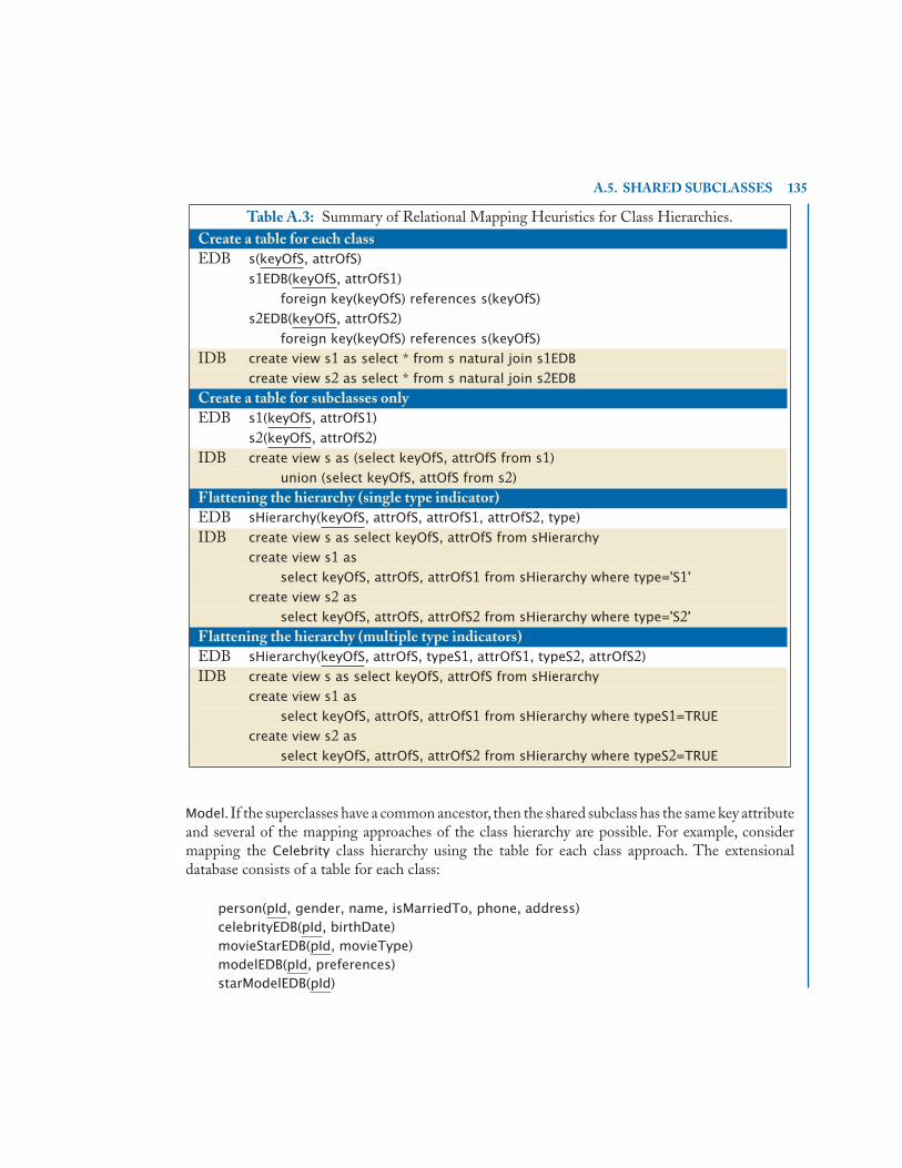
A.5. SHARED SUBCLASSES 135
Table A.3: Summary of Relational Mapping Heuristics for Class Hierarchies.Create a table for each classEDB s(keyOfS, attrOfS)
s1EDB(keyOfS, attrOfS1)
foreign key(keyOfS) references s(keyOfS)
s2EDB(keyOfS, attrOfS2)
foreign key(keyOfS) references s(keyOfS)
IDB create view s1 as select * from s natural join s1EDB
create view s2 as select * from s natural join s2EDB
Create a table for subclasses onlyEDB s1(keyOfS, attrOfS1)
s2(keyOfS, attrOfS2)
IDB create view s as (select keyOfS, attrOfS from s1)
union (select keyOfS, attOfS from s2)
Flattening the hierarchy (single type indicator)EDB sHierarchy(keyOfS, attrOfS, attrOfS1, attrOfS2, type)
IDB create view s as select keyOfS, attrOfS from sHierarchy
create view s1 as
select keyOfS, attrOfS, attrOfS1 from sHierarchy where type='S1'
create view s2 as
select keyOfS, attrOfS, attrOfS2 from sHierarchy where type='S2'
Flattening the hierarchy (multiple type indicators)EDB sHierarchy(keyOfS, attrOfS, typeS1, attrOfS1, typeS2, attrOfS2)
IDB create view s as select keyOfS, attrOfS from sHierarchy
create view s1 as
select keyOfS, attrOfS, attrOfS1 from sHierarchy where typeS1=TRUE
create view s2 as
select keyOfS, attrOfS, attrOfS2 from sHierarchy where typeS2=TRUE
Model. If the superclasses have a common ancestor, then the shared subclass has the same key attributeand several of the mapping approaches of the class hierarchy are possible. For example, considermapping the Celebrity class hierarchy using the table for each class approach. The extensionaldatabase consists of a table for each class:
person(pId, gender, name, isMarriedTo, phone, address)celebrityEDB(pId, birthDate)movieStarEDB(pId, movieType)modelEDB(pId, preferences)starModelEDB(pId)

136 A. MAPPING OBJECT-ORIENTED CONCEPTUAL MODELS
To support the appropriate inherited attributes, the intensional schema defines views forCelebrity, MovieStar, Model, and StarModel. For brevity, only the StarModel view is shown.
create view starModel asselect c.pId, c.gender, c.name, c.isMarriedTo, c.phone,
c.address c.birthDate, ms.movieType, m.preferencesfrom (((starModelEDB s natural join modelEDB m)
natural join movieStarEDB ms)natural join celebrity c);
If the hierarchy is flattened, then the extensional schema consists of the celebrityHierarchytable.
celebrityHierarchy(pId, birthDate, movieStar, movieType, model, preferences)
The intensional schema defines the starModel view based on both Boolean attributes movi-eStar and model being TRUE. Note that this view assumes the relation celebrity is already defined,containing all of the attributes describing the Celebrity class.
create view starModel asselect c.pId, c.gender, c.name, c.isMarriedTo, c.phone,
c.address, c.birthDate, h.movieType, h.preferencesfrom celebrity c join celebrityHierarchy hwhere h.movieStar and h.model;
Since the mapping approach that creates a table for subclasses only requires a disjoint andtotal specialization, this mapping approach is not applicable to shared subclasses that are inherentlyoverlapping and partial specializations.
A.6 CATEGORIESA category in the EER or the Xor constraint in UML requires the introduction of a surrogate keyattribute for mapping to the relational data model. The surrogate key represents a mechanism forthe database system to generate a unique value for a category, which models a union of two ormore different types of classes having different primary key attributes. For the Sponsor categoryof Figure 1.23 and the Sponsor Xor constraint of Figure 1.24, a table is created for the Sponsorcategory containing the surrogate key attribute sponsorCode. The sponsorCode surrogate key isalso an attribute of each of the tables for the unioned superclasses person and company. Sincethere is only one sponsor for a modeling project, the surrogate key sponsorCode is included in themodelingProjectEDB table to identify the sponsor of the project.
sponsor (sponsorCode)person (pId, name, phone, gender, address, sponsorCode)
foreign key (sponsorCode) references sponsor(sponsorCode)company (cId, cName, sponsorCode)

A.6. CATEGORIES 137
foreign key (sponsorCode) references sponsor(sponsorCode)modelingProjectEDB (projectId, description, sponsorCode)
foreign key (projectId) references project (projectId)foreign key (sponsorCode) references sponsor(sponsorCode)
Since a category represents the union of its superclasses, a schema-level assertion enforcesthat the surrogate key appears in one of the superclasses:
create assertion sponsorCategoryUnioncheck (not exists
(select *from sponsor swhere s.sponsorCode not in
(select p.sponsorCodefrom person punionselect c.sponsorCodefrom company c)));
A category is also an exclusive-or of its superclasses as shown in the UML diagram of Fig-ure 1.24. Another schema-level constraint for a category checks that a surrogate key value is not inmore than one superclass:
create assertion sponsorCategoryXorcheck (not exists
(select *from sponsor swhere s.sponsorCode in
(select p.sponsorCodefrom person pintersectselect c.sponsorCodefrom company c)));
If a category is constrained to be total, then every instance of each superclass must participatein the categorization and be an instance of the category subclass. To enforce the total categorizationconstraint, add a constraint requiring that the surrogate key attribute in each superclass table is notnull.
sponsor (sponsorCode)person (pId, name, phone, gender, address, sponsorCode)
foreign key (sponsorCode) references sponsor(sponsorCode)constraint totalPerson not null (sponsorCode)
company (cId, cName, sponsorCode)foreign key (sponsorCode) references sponsor(sponsorCode)

138 A. MAPPING OBJECT-ORIENTED CONCEPTUAL MODELS
constraint totalCompany not null (sponsorCode)
A.7 CHECKPOINT
The mapping of the semantic constructs of the object-oriented conceptual models to the relationaldata model consists of three parts: an extensional schema of stored tables (including column andtable-level constraints), an intensional schema of view definitions, and the schema-level constraintsthat provide the semantic checking of the relations.
The mapping of classes, attributes, and associations emphasized how the constraints inherentin the conceptual model can be realized in the corresponding mapping to the relational data model.Bidirectional associations of M:N, 1:N, and 1:1 cardinality ratios mapped to tables consisting of theprimary key attributes of both classes involved in the association and any descriptive attributes of theassociation. The referential integrity constraints are enforced by the specification of foreign keys inthe schema definition.The enforcement of participation and multiple constraints were also discussedas well as recursive associations, n-ary associations, identifying relationships, and the navigability ofassociations.
The mapping of class hierarchies covered three approaches:
1. Creating a table for each class,
2. Creating a table for subclasses only, and
3. Flattening the hierarchy.
The guiding design principle of the mapping of the class hierarchies mapped a class C to a relationof the same name containing all the attributes that describe the class, including both specialized andinherited attributes.The relation for a class could be stored as a table as part of the extensional schemaor as a view as part of the intensional schema. The naming convention for class relations allowed thereuse of the templates for verifying specialization constraints (disjoint, total, and attribute-defined)across all three mapping approaches.
The appendix concluded with a discussion of the mapping of shared subclasses and categories.Several schema-level constraints are necessary to enforce the constraints inherent in a categorizationas the (exclusive) union of its superclasses.
A.8 BIBLIOGRAPHIC REFERENCES
The extensional and intensional database terminology is from the research area known as de-ductive databases, which investigated logic programming languages as database query lan-guages [Ramakrishnan and Ullman, 1995]. Most deductive database prototypes used facts to storethe extensional database and rules to define the intensional database. The mapping of object-oriented conceptual data models to the relational data model given in this chapter is a synergy

A.8. BIBLIOGRAPHIC REFERENCES 139
of the myriad approaches presented in the deductive database literature, other database text-books [Elmasri and Navathe, 2010], and the semantic data modeling research.
The mapping of the object-oriented conceptual models to the relational model also forms thebasis for understanding object relational mapping (ORM) tools. ORMs provide an object view ofrelational data. The use of ORMs is driven by the need of today’s applications, which are written inOOPLs, that must access data stored in a relational database. ORMs provide a higher level of ab-straction for an OOPL to access relational data over the use of a call-level interface in which an APIis used to query the relational database and process the result set. In an ORM, annotations or config-uration specifications assist in the mapping between relations and objects. There are several ORMsavailable including the Java Persistence API [Yang, 2010] and the Hibernate [Bauer and King, 2006]open-source implementation, which has a corresponding NHibernate [Kuate et al., 2009] for the.NET Framework. Some ORMs also provide support for the generation of the relational schemafrom the object schema. Hibernate supports three strategies for mapping inheritance: table per classhierarchy, table per subclass, and table per concrete class. Additional mappings involving the unionand join of subclasses are possible.
In Chapter 2, the LINQ language was presented as an object query language for OODBs.LINQ also provides querying capabilities over collections of relational tuples using LINQ toSQL [Calvert and Kulkarni, 2009], which is an ORM since it provides an object view of relationaldata.


141
Bibliography
J. Albahari. LINQPad, 2010. http://www.linqpad.net 64
K.Arnold, J.Gosling,and D.Holmes.The Java(TM) Programming Language (4th Edition),Addison-Wesley, 2005. 28
M. Atkinson, F. Bancilhon, D. DeWitt, K. Dittrich, D. Maier, and S. Zdonik. The object-orienteddatabase system manifesto. In Proc. of the 1st Int. Conf. on Deductive and Object-Oriented Databases,Kyoto, Japan. Elsevier Science Publishers B.V (NorthHolland), 1990. 27, 114
C. Bauer and G. King. Java Persistence with Hibernate, Manning, 2006. 139
G. Booch. Object-Oriented Analysis and Design with Applications, Second Edition, Ben-jamin/Cummings Publishers, Redwood City, California, 1994. 30
P. Brown. Object-Relational Database Development: a Plumber’s Guide, Prentice Hall, Inc., UpperSaddle River, New Jersey, 2001. 114
C. Calvert and D. Kulkarni. Essential LINQ, Addison-Wesley Professional, 2009. 64, 139
R. G. G. Cattell, , D. K. Barry, M. Berler, J. Eastman, D. Jordan, C. Russell, O. Schadow,T. Stanienda,and F. Velez (editors). The Object Data Standard: ODMG 3.0, Morgan Kaufmann, 2000. 64
A. Chaudhri and R. Zicari (editors). Succeeding with Object Databases: A Practical Look at Today’sImplementations with Java and XML, J. Wiley, 2000. 64, 144
P. Chen. The Entity Relationship Model - Toward a Unified View of Data. In Transactions onDatabase Systems, vol. 1, no. 1, March 1976. DOI: 10.1145/320434.320440 27
O.-J. Dahl, B. Myhrhaug, and K. Nygaard. Simula 67 Common Base Language, Norwegian ComputerCenter, Oslo, Norway, 1967. 27
C.J.Date and H.Darwen.Foundations for Object/Relational Databases:TheThird Manifesto,Addison-Wesley, Menlo Park, California, 1998. 114
S. W. Dietrich and M. Chaudhari. The Missing LINQ between Databases and Object-OrientedProgramming: LINQ as an Object Query Language for a Database Course. Journal of Computingin Small Colleges, Volume 24, Number 4, pages 282-288, 2009. 64
S. Edlich, H. Hörning, R. Hörning, and J. Paterson. The Definitive Guide to db4o, Apress, 2006. 64

142 BIBLIOGRAPHY
R. Elmasri and S. Navathe. Fundamentals of Database Systems, Sixth Edition, Addison-Wesley, Read-ing, Massachusetts, 2010. 27, 139
R. Elmasri, J. Weeldreyer, and A. Hevner. The Category Concept: An Extension to the EntityRelationship Model. International Journal on Data and Knowledge Engineering, vol. 1, no. 1, May1985. DOI: 10.1016/0169-023X(85)90027-8 27
R. Elmasri and G. Wiederhold. Structural Properties of Relationships and their Repre-sentations. In Proceedings of the National Computer Conference, AFIPS, volume 49, 1980.DOI: 10.1109/AFIPS.1980.87 27
M. Fowler. UML Distilled: A Brief Guide to the Standard Object Modeling Language (3rd Edition),Addison-Wesley Publishers, 2003. 30
A. Goldberg and D. Robson. Smalltalk-80: The Language and Its Implementation, Addison-WesleyPublishers, Reading, Massachusetts, 1983. 27
P. Gulutzan and T. Pelzer. SQL-99 Complete Really!, Miller Freeman, Lawrence, Kansas, 1999. 114
G. Held, M. Stonebraker, and E. Wong. Ingres - A Relational Database System. In Proceedings ofthe AFIPS National Computer Conference, pages 409-416, 1975. 114
R. Hull and R. King. Semantic Data Modeling: Survey, Applications, and Research Issues. In ACMComputing Surveys, vol. 19, no. 3, September, 1987. DOI: 10.1145/45072.45073 27
I. Jacobson, M. Christerson, P. Jonsson, and G. Overgaard. Object-Oriented Software Engineering: AUse Case Driven Approach, Addison-Wesley Publishers, Wokingham, England, 1992. 28
S. Koshafian and G. Copeland. Object Identity. In Readings in Object-Oriented Database Systems, S.Zdonik and D. Maier (editors), Morgan Kaufmann, 1989. 27
P. H. Kuate, C. Bauer, G. King, and T.Harris. NHibernate in Action, Manning, 2009. 139
M. E. S. Loomis and A. Chaudhri (editors). Object Databases in Practice, Prentice Hall, 1997. 64
F. Marguerie, S. Eichert, and J. Wooley. LINQ in Action, Manning, 2008. 64
J. Melton and A. Simon. SQL:1999 Understanding Relational Language Components, Morgan Kauf-mann Publishers, San Francisco, California, 2001. 114
J. Melton. Advanced SQL:1999 Understanding Object-Relational and Other Advance Features, MorganKaufmann Publishers, San Francisco, California, 2002. 114
B. Meyer. Object-Oriented Software Construction, Prentice Hall Publishers, New York, New York,1988. 27

BIBLIOGRAPHY 143
R. Muller. Database Design for Smarties: Using UML for Data Modeling, Morgan Kaufmann Pub-lishers, San Francisco, California, 1999. 30
ODBMS.ORG Object Database Management Systems: The Resource Portal for Education andResearch, R. Zicari (editor), http://odbms.org 64
OMG Unified Modeling Language Specification, Version 2.3, Object Management Group, May 2010,http://www.omg.org/spec/UML/. 30
Oracle Database Object-Relational Developers Guide, http://download.oracle.com/docs/cd/B28359_01/appdev.111/b28371/adobjint.htm. 114
J. Peckham and F. Maryanski. Semantic Data Models. In ACM Computing Surveys, vol. 20, no. 3,pages 153-189, 1988. DOI: 10.1145/62061.62062 27
R. Ramakrishnan and J. Ullman. A Survey of Deductive Databases. Journal Of Logic Programming,vol. 23, no. 2, pages 125-149, 1995. DOI: 10.1016/0743-1066(94)00039-9 138
L. Rowe and M. Stonebraker.The Postgres Data Model. In Proceedings of the Thirteenth InternationalConference on Very Large Data Bases, Brighton, England, pages 83-96, 1987. 114
J. Rumbaugh, M. Blaha, W. Premerlani, F. Eddy, and W. Lorensen. Object-Oriented Modeling andDesign, Prentice Hall Publishers, Englewood Cliffs, New Jersey, 1991. 28
J. Rumbaugh, I. Jacobson, and G. Booch. The Unified Modeling Language Reference Manual (2ndEdition), Addison-Wesley, Upper Saddle River, New Jersey, 2004. 30
J. Schmuller. Sams Teach Yourself UML in 24 Hours (3rd Edition), SAMS Publishing, Indianapolis,Indiana, 2004. 30
J. Smith and D. Smith. Database Abstractions: Aggregation and Generalization. In Transactions onDatabase Systems, vol. 2, no. 2, June 1977. DOI: 10.1145/320544.320546 27
M. Stonebraker, L. Rowe, B. Lindsay, J. Gray, M. Carey, M. Brodie, P. Bernstein, and D. Beech.Third Generation Database System Manifesto. In SIGMOD Record, vol. 19, no. 3, pages 31-44,1990. DOI: 10.1145/101077.390001 114
M. Stonebraker, Object-Relational DBMSs: The Next Great Wave, Morgan Kaufmann, San Francisco,California, 1995. 114
B. Stroustrup. The C++ Programming Language, 1st Edition, Addison-Wesley, 1986. 27
B. Stroustrup. The C++ Programming Language, Special Edition, Addison-Wesley, 2000. 28
S. D. Urban. Database Models. In Encyclopedia of Electrical and Electronics Engineering, John G.Webster (editor), John Wiley & Sons, Inc., vol. 4, pages 604-629, 1999. 30

144 BIBLIOGRAPHY
S. D. Urban, S. W. Dietrich, and P. Tapia. Mapping UML Diagrams to Object-Relational Schemasin Oracle 8. In [Chaudhri and Zicari, 2000]. 114
S. D. Urban and S. W. Dietrich. Using UML Class Diagrams for a Comparative Anal-ysis of Relational, Object-Oriented, and Object-Relational Database Mappings. In ACMSIGCSE International Conference on Computer Science Education, Reno, Nevada, February, 2003.DOI: 10.1145/792548.611923 114
Versant, db4o, http://www.db4o.com 64
G. Wiederhold and R. Elmasri. The Structural Model for Database Design. In Proceedings of theEntity Relationship Conference, 1979. 27
D. Yang. Java Persistence with JPA, Outskirts Press, 2010. 139

145
Authors’ Biographies
SUZANNE W. DIETRICHSuzanne W. Dietrich is an associate professor in the Applied Computing program within the Divi-sion of Mathematical and Natural Sciences at Arizona State University.Her research interests includedatabase query languages, data modeling, and computer science education. Dr. Dietrich’s researchhas been supported by grants from the National Science Foundation, including the maintenanceof materialized views over heterogeneous structured data sources in a distributed environment withevents and streams; the integration of declarative, object, and active features for distributed multi-tiered applications; and the development of novel approaches to undergraduate database education.She is recognized by the ACM as a Distinguished Educator and is the author of UnderstandingRelational Database Query Languages (Prentice Hall 2001).
SUSAN D. URBANSusan D. Urban is a professor in the Department of Computer Science at Texas Tech University.Her research interests include data and process modeling as well as integrated techniques for event,rule, and transaction processing to address data consistency and active behavior in distributed, data-centric applications. Dr. Urban has been the recipient of several grants from the National ScienceFoundation for her research on constraints, active rule processing in centralized and distributedenvironments, data consistency issues in service-oriented environments, the use of databases inengineering design, and the development of innovative teaching concepts for database instruction.She has published over 100 refereed papers and book chapters on the results of her research.

147
Index
abstract class, 22Abstract Enterprise
mapping to relational data model,116–124
mapping to SQL standardobject-relational data model, 87–100
ODL, 33–38relational schema using unidirectional
navigability, 125SQL standard object-relational schema,
97, 98UML, 7
Abstract EnterpriseER, 6
array type, 68–70association, 8
bidirectional, 13binary, 11class, 11n-ary, 11recursive, 11reified, 12ternary, 11unidirectional, 13
candidate key, 6cardinality ratio, 8category, 23class, 3class hierarchy, 15
EER, 16
UML, 16collection type, 68–70, 112column object, 107complex objects, 4composite attribute, 7constructed type, 66
db4o, 61–63derived attribute, 7discriminator, 21distinct type, 70–72
embedded object, 103encapsulation, 4, 73Enhanced Entity-Relationship, 1extensibility, 4extent, 32
generalization, 15
Hollywood Enterprisedescription, 16EER, 28mapping to relational data model,
124–138ODL, 41UML, 29UML reified, 45
identifying owner, 14identifying relationship, 14impedance mismatch, 2inheritance, 5

148 INDEX
Language INtegrated Query, see LINQlate binding, 5LINQ, 54–61
=>, 54aggregation, 58All, 57anonymous types, 55Any, 56Average, 58Contains, 56Count, 58deferred query execution, 60Distinct, 55embedded queries, 56Except, 58extension methods, 54First, 58grouping, 59immediate execution, 60Intersect, 58into, 59Last, 58let, 59Max, 58Min, 58orderby, 57path expressions, 54quantification, 56query comprehension syntax, 54query operators, 54set membership, 56Single, 55Sum, 58Take, 58Union, 58
multiple inheritance, 22multiplicities, 9multivalued attribute, 7
Object Data Management Group, see ODMGobject database, 1Object Definition Language, see ODLobject identity, 4, 76Object Query Language, see OQLobject reference, 76object table, 108object type, 103object-oriented databases, 1object-relational databases, 1, 65–113ODL, 32–42
:, 33attribute, 32class, 32composite key, 32extends, 32extent, 32inheritance, 32key, 32mapping, 33–42
binary relationship, 34cardinality ratios, 35category, 40class, 33class hierarchies, 40composite attribute, 34constraints, 38derived attribute, 34Hollywood Enterprise, 41multivalued attribute, 34n-ary associations, 37recursive association, 36reified association, 35single-valued attribute, 34specialization constraints, 40unidirectional associations, 37weak entity, 38
relationship, 32

INDEX 149
ODMG, 31–32OQL, 42–53
aggregation, 51define, 47element, 50embedded queries, 48first, 51group by, 52having, 52last, 51methods, 48order by, 50path expressions, 46quantification, 49set membership, 49
Oracle object-relational case study, 100–113collection type, 112column object, 107constructor method, 108deref, 110embedded object, 103final, 108function, 107is of, 111method specification, 107nested table, 112, 113not final, 108object identifier, 108object table, 108object type, 103path expression, 111pragma declaration, 107procedure, 107ref, 109reference type, 109row object, 108scope, 109self, 107substitutable table, 108, 111
treat, 111type hierarchies, 108under, 108value, 110varray, 112, 113
overloading, 5overriding, 5
partial key, 14participation constraint, 8pseudoattribute, 21
qualified association, 15
reference type, 84–87, 109reification, 12relational data model, 115–138
extensional schema, 115intensional schema, 115mapping
associations, 117–124attribute-defined subclass, 130bidirectional association, 117–118categories, 136class, 116class hierarchies, 124–133composite attribute, 116composite key, 117derived attribute, 116foreign key, 117multiplicity constraint, 119–120multivalued attribute, 117n-ary associations, 121participation constraint, 119–120primary key, 117recursive associations, 121relationships, 117–124shared subclasses, 133simple attribute, 116

150 INDEX
specialization constraint, 128, 130–133summary of class hierarchies, 133summary of classes and associations,
124surrogate key, 136uni-directional association, 122–123weak entity, 123
notational conventions, 115relational database systems, 1relationship, 8role names, 11row object, 108row type, 67
School Database Enterprisedescription, 66illustration of object-relational features,
66–87mapping to Oracle object-relational
features, 100–113Oracle object-relational schema, 105, 106SQL standard object-relational schema,
101, 102UML, 67UML annotated for Oracle, 104
specialization, 15attribute-defined, 20user-defined, 20
specialization constraintcomplete, 16disjoint, 16EER, 18object-oriented databases, 40relational data model, 128, 130–133total, 16UML, 18
SQL object-relational standard, 66–100array, 68array type, 68
built-in method, 73cardinality, 69collection type, 68constructed type, 66constructor function, 73create method, 75create type, 71deref, 87dereference operator, 86derived, 77distinct type, 70encapsulation, 73final, 72finality clause, 73function, 73instantiable, 77mapping, 87–100
bidirectional association, 89–92candidate key, 95category, 99class hierarchies, 98composite attribute, 88derived attribute, 88inverse relationship, 89inverse relationships, 95multiplicity constraint, 95multivalued attribute, 88n-ary associations, 93participation constraint, 95qualified association, 94recursive association, 92, 95referential integrity, 95single-valued attribute, 88specialization constraint, 99summary of classes, attributes, and
associations, 96total participation, 90, 95unidirectional association, 94weak entity, 94

INDEX 151
mutator function, 73new, 74not final, 73not instantiable, 77observer function, 73only, 83procedure, 73ref, 84ref is, 77references are checked, 86row, 67row type, 67scope, 86self-referencing column, 76stored procedure, 73structured type, 72syntax for
reference type, 85typed table, 78user-defined type, 71
system generated, 77typed table, 76–79under, 79user-defined, 77user-defined method, 73user-defined type, 70
structured type, 72–73subclasses, 15substitutable table, 108superclasses, 15
table hierarchies, 79–84type hierarchies, 79–81, 108typed table, 76–79
Unified Modeling Language, 1user-defined type, 70–76
weak entity, 14
xor constraint, 25