fundamentals of structural design part of steel structurespeople.fsv.cvut.cz/~sokol/fstd/copy of...
TRANSCRIPT

1
1
Fundamentals of Structural DesignPart of Steel Structures
Civil Engineering for Bachelors133FSTD
Teacher: Zdeněk SokolOffice number: B619
2
Syllabus of lectures
1. Introduction, history of steel structures, the applications and some representative structures, production of steel
2. Steel products, material properties and testing, steel grades3. Manufacturing of steel structures, welding, mechanical fasteners4. Safety of structures, limit state design, codes and specifications for the
design5. Tension, compression, buckling6. Classification of cross sections, bending, shear, serviceability limit states7. Buckling of webs, lateral-torsional stability, torsion, combination of
internal forces 8. Fatigue9. Design of bolted and welded connections10. Steel-concrete composite structures11. Fire and corrosion resistance, protection of steel structures, life cycle
assessment
2
3
Scope of the lecture
Basic principles of the composite structures
Shear connectors
Composite beams
Composite columns
Steel-concrete slabs
4
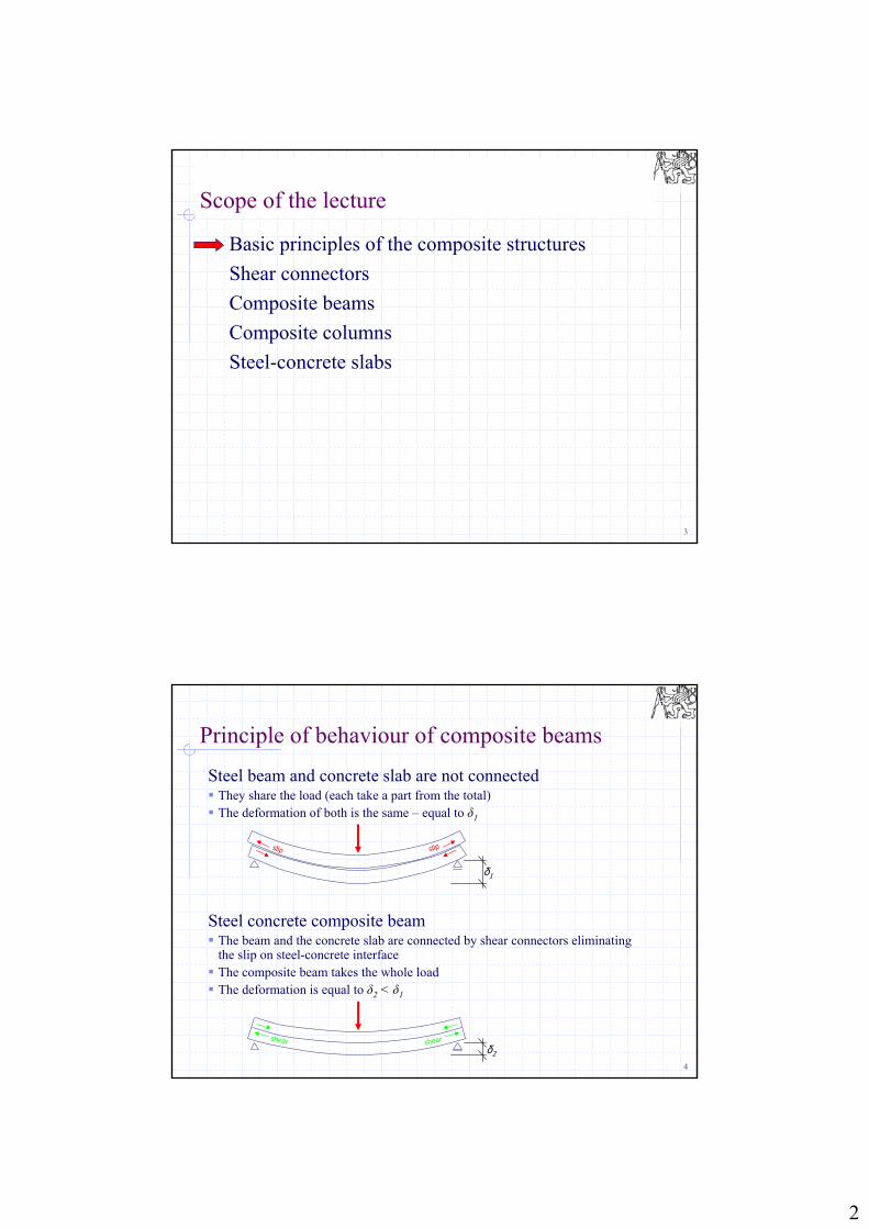
Steel beam and concrete slab are not connected They share the load (each take a part from the total) The deformation of both is the same – equal to δ1
Steel concrete composite beam The beam and the concrete slab are connected by shear connectors eliminating
the slip on steel-concrete interface The composite beam takes the whole load The deformation is equal to δ2 < δ1
Principle of behaviour of composite beams
δ1
slip slip
δ2
shear shear

3
5
Steel concrete composite structures
Advantages Convenient stresses
(concrete in compression / steel in tension) Saving expensive material (steel) - low cost of the structure Increase of stiffness Better fire resistance (compared to steel structures) – no need for additional fire
protection – low cost of the structure
Steel concrete composite elements Beams Columns Composite slabs Shear stud
Steel concrete beam section with welded stud
providing shear connection
6
Beam with welded shear studs

4
7
Standards for design of composite structures
European standard EN 1994-1-1
Design strength concrete ………
steel ………..….
reinforcement …
shear connectors
cckcd ff 85,0
0 Myyd ff
ssksd ff
a
c
a, c
Steel
Concrete
5,1 c
0,1 0 M
15,1 s
25,1 V
Stress-strain diagram of steel and concreteNote: for equal strain εa,c, steel gets much higher stress than concrete
because of different modules of elasticity
8
Scope of the lecture
Basic principles of the composite structures
Shear connectors
Composite beams
Composite columns
Steel-concrete slabs

5
9
Welded studs
Common, cheap, simple to installConvenient F – relationship
(high resistance and ductility)
Need of strong electric source for welding
Studs welded to the steel beam Shear stud
10Semi-automatic welding of the shear studs
Welding of shear studs

6
11
Advantages of studs
Deformation of ductile studsHigh deformation capacity of studs allows for plastic distribution of shear forces among the studsAs the studs at the ends of the beam are overloaded, they deform and cracks in the concrete appear, which leads to small slip of the concrete slab, this causes the other studs are loaded by increasing forces
Cracks in concreteSlip
12
Resistance of studs
Characteristic resistance of the stud Steel failure
Concrete failure
fu ultimate strength of material of studs, max. 500 MPa
Reduction due to stud height Short stud
Long stud
48,0
2dfP uRk
cmckRk EfdP 229,0
12,0
d
h
0,1
43 d
h
d
h4

7
13
Perforated strips
Various types exist worldwideThe resistance can be increased by reinforcement placed into the holesNon-ductile shear connectionTwo types are used in Czech Republic: height 50 mm, thickness 10 mm, holes d = 32 mm height 100 mm, thickness 12 mm, holes d = 60 mm
14
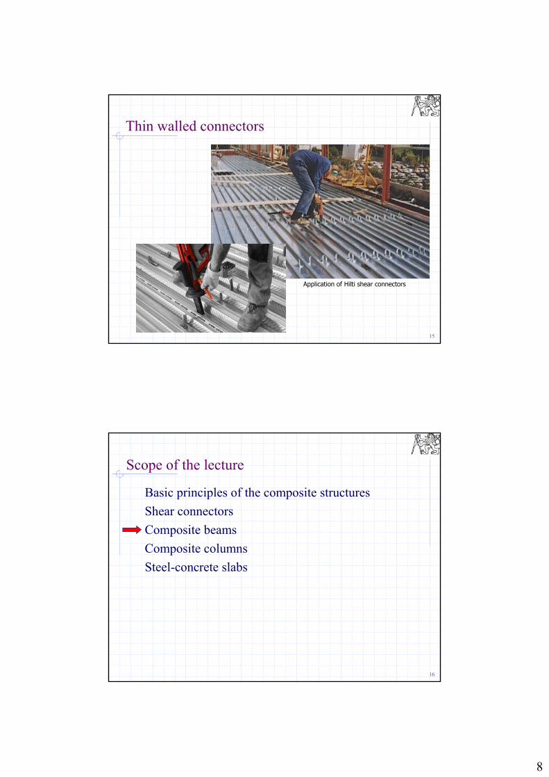
Thin walled connectors
Manufactured by Hilti
Zinc-coated steel sheet, thickness 2 mm
Easy to apply, no need for electricity for welding
Connected to steel beams by two shot nails
Height from 80 up to 140 mm
Expensive refurbishment
Hilti HVB shear connectors
Range of Hilti HVB connectors
8
15
Thin walled connectors
Application of Hilti shear connectors
16
Scope of the lecture
Basic principles of the composite structures
Shear connectors
Composite beams
Composite columns
Steel-concrete slabs

9
17
Composite beams
Shear connectors to avoid slip between steel beam and concrete slab
Composite beamComposite beam with concrete slab cast in the corrugated sheet
18
Effective cross section
The stress in the concrete slab is not uniform because of effect of shear lag
Idealized stress distribution (i.e. uniform stress on the effective width beff) is considered in the concrete slab
Considering imply supported beams, the effective width beff is equal to
Real stressdistribution in the concrete slab
Idealized stress in the concrete
4
Lbeff
Stress distribution in the concrete slab
Effective width of the concrete slab
10
19
Classification of cross sections
Beam flange connected to the concrete slab by shear connectors is assumed to be fully stabilized - no local buckling of the flange can occur – Class 1 for any c/t ratio
The other parts are classified in similar way as normal steel beams
20
Resistance of the beam
Two cases should be distinguished: Full shear connection
(the shear connection is not critical part of the beam) This is the preferable way of design
Partial shear connection (shear connection limits the resistance of the beam) It is used in cases when the number of the connectors required for full shear
connection does not fit on the beam and smaller number of the connectors must be used Stiffness of the beam decrease - deformation increase
Check of cross section – plastic stress distribution at ULS (full shear connection) Positive plastic bending moment capacity is evaluated with one of the
following options Neutral axis in the slab Neutral axis in the beam
Negative plastic moment capacity needs to be evaluated at supports of continuous beams, etc.

11
21
Plastic bending moment capacity
ac FF
...85,0 xf
Af
xba
ya
c
ckeff
rFrFM caRdpl ,
Full shear connection
Assumption: neutral axis is in the concrete slabForce equilibrium equation to get the depth of concrete zone in compression
Moment equilibrium equation to get the bending moment capacity
but x must be smaller than depth of the slab
22
Plastic bending moment capacity
...21 xFFF aac
22 112,
dhF
dhFM aaacRdpl
Full shear connection
Assumption: neutral axis is in the steel sectionForce equilibrium equation to get the depth of concrete zone in compression
Moment equilibrium equation to get the bending moment capacity
(limits for x exist)

12
23
Criteria to be checked
Ultimate Limit States Moment resistance of critical cross section
Resistance in shear
Resistance in longitudinal shear (resistance of shear connectors)
Serviceability Limit States Elastic behaviour
Deflections
24
Resistance in shear
See shear resistance of steel beams
The concrete slab has no effect on the shear resistance
Av shear area = area of the beam web
0
,3 M
yvRdpl
fAV
Shear area of I sections

13
25
Shear connection
Shear connectors transfer longitudinal shear V
Ductile shear connectors: the connectors can be uniformly distributed Shear force to be transferred by connectors
Number of connectors on half-span:
c
ckccf
fAF
85,0
Rd
cff P
Fn
a aaaaa
26
Shear connection
Shear connectors transfer longitudinal shear V
Non-ductile connectors: the connectors follow shear force distribution
i
cEd
I
SVV
VEd shear force on the beam,Si static moment of effective cross section of slab
to the centre of gravity of the beam,Ii moment of inertia of the beam
a3 a5a4a2a1

14
27
Serviceability limit states
Service load is assumed for the calculations (G = Q = 1,0; M = 1,0)
Beam is in elastic stage – this should be checked by calculating the maximum stress in the steel and concrete and comparing it to the yield limit of steel and to the concrete strength
Deflections
Cracking of concrete (limit of crack width)Limit crack width wk = 0,3 mmThis is controlled by the slab reinforcement
The assembling procedure has significant effect on both the stress and the deflection of the beam
28
Elastic behaviour
Assumption of Navier’s hypothesis (planar cross-section after deformation) Components and maximum stress Concrete (0,85 fck / c ) Steel (fy / M0) Reinforcement (fsk / s)

15
29
Properties of idealized cross section
Concrete slab is transformed to the equivalent steel partThe ratio at which the dimensions are modified is
Ea is modulus of elasticity of steelEcm is modulus of elasticity of concrete, the factor 0,5 is used to take into
account the creep in a simplified way
Area of cross section Ai
Centre of gravity Moment of inertia Ii
sc
ai An
AAA
cm
a
E
En
5,0
......., iyI Idealized section of composite beam
30
Assembling procedure
Has influence on deformation and elastic stress distribution (but not on Mpl,Rd)
Two procedures can be used
Without scaffoldingTwo stages need to be considered:
the assembly stage, when steel beam is loaded by weight of fresh concrete (and some temporary load presented at the assembling) - no composite action
the final stage, when the concrete is hard and ready to carry the load - the composite beam has to carry all the load
In elastic calculation, the stress from the assembly stage (from the weight of the fresh concrete) and from the remaining load (other dead load applied after the concrete gets hard and from variable load) add
On scaffoldingThe weight of the fresh concrete is supported by temporary structure -
scaffolding, therefore no stresses and deformation occur, all the load is resisted by the composite beam

16
31
Assembling with scaffoldingStresses, deflections
Stress at upper edge of the concrete slab
Stress at lower edge of steel section
Deformation (for simply supported beam with uniformly distributed load)
Note: easy method for the designsaves the steel - the beams are smaller as only the composite beam is loadedcheap? - consider the price of rent and erection of the scaffoldingeffective for large spans, i.e. spans exceeding 7 m
i,y
cEkc I
zM
n
1
i,y
aEka I
zM
iya
k
IE
lv
,
4
384
5
k,cc f
ya f
32
Assembling without scaffoldingStresses
Assebling stageThe load at assembly should be considered, i.e. self weight of the beam, weight of the fresh concrete and people working with the concreteStress in the steel section (top and bottom edges)
Final stageThe remaining load should be considered, i.e. the floor and ceiling and any variable loadStress in the steel section (bottom edge)
Stress in the concrete (top surface of the slab)
y
.Eka I
zM 11
i,y
a.Eka I
zM 22
ya f1
i,y
c.Ekc I
zM
n21
No stress in the concrete
σ1
zz

17
33
No stress in the concrete
σ1
zz
σ2
z az c
Assembling with scaffoldingStresses
Total stressThe total stress is obtained as the sum of the previousStress in the steel section (bottom edge)
Stress in the concrete (top surface of the slab)
Note: more complicated method for the design (two situations need to be considered)the beams are bigger - usually the assembling stage limits the size of the steel beameffective for small spans, i.e. spans up to 7 m
21 aaa
20 cc
34
Assembling with scaffoldingDeformation
Deformation (for simply supported beam with uniformly distributed load)At assembly stageThe load at assembly should be considered, i.e. self weight of the beam, weight of the fresh concrete and people working with the concreteThe moment of inertia of the steel section only (Iy) is used
At final stageThe remaining load should be considered, i.e. the floor and ceiling and any variable loadThe moment inertia of the composite beam (Iy,i) is used
Total deformationThe total stress is obtained as the sum of the previous
i,ya
k
IE
lv 42
2 384
5
ya
k
IE
lv 41
1 384
5
21

18
35
Scope of the lecture
Basic principles of the composite structures
Shear connectors
Composite beams
Composite columns
Steel-concrete slabs
36
Columns
Fully encased columns
Partially encased columns
Concrete filled hollow sections (circular, rectangular)

19
37
Columns
38
Simplified method ofresistance evaluation of columns
Criteria
Columns with double-symmetric steel sections
Constant section along length
0,2 < < 0,9, where
0,2 < hc/bc < 5,0
Relative slenderness of column
Area of the reinforcement should be max. 6 % of concrete area
Rd,pl
aya
N
fA
02 ,

20
39
Centric compression
Full plastification of all parts
Concrete filled hollow sections
... use fck instead of 0,85 fck
Increase of concrete strength confined by the steel section
s
sks
c
ckc
a
yaRd.pl
fA
f,A
fAN
850
40
Buckling resistance
Rd.plEd NN
... reduction factor (buckling factor) as for steel members
Use buckling curves a, b, c
cr
Rd.pl
N
N

21
41
Critical load of composite element
Bending stiffness
buckling lengthmodulus of elasticity of steelmodulus of elasticity of concrete
Ia, Ic, Is moments of inertia of steel part, concrete part and reinforcement to the centroidal axis
sa EE
cmE
ssccmaae IEIE,IEEI 60
2
2
e
crEI
N
42
Compression and bending
Interaction curve for combined MEd + NEd

22
43
Joints of composite structures
Joints are encased in concrete afterwards (to maintain the same fire resistance of the joints as of the other parts)
44
Scope of the lecture
Basic principles of the composite structures
Shear connectors
Composite beams
Composite columns
Steel-concrete slabs

23
45
Concrete slab cast on corrugated steel sheets
Corrugated sheet filled by concrete1. Fresh concrete = assembling stage: load to sheet
2. After hardening of concrete: sheet = reinforcement (plus standard reinforcement when necessary )
For static loading
46
Concrete slabs cast on corrugated steel sheets
Shear connection mechanical connection assured by nops or profiling in sheet
frictional connection of profiles with self locking shape profiles
end stop by welded studs
end stop by deformed ribs of self locking shape profiles
Mechanical connection Frictional connection
Shear connection End connection

24
47
Slip between steel and concrete
48
Thank you for your attention