furnace humidifierwaithumidifiers.com/instructions/wait6000.pdf · 1. the humidifier body is...
TRANSCRIPT

Model 6000Model 6000
FLOW-THROUGHFURNACE HUMIDIFIER
Installation/OperatingInstructions
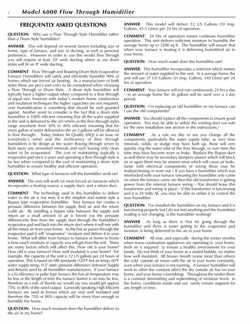
FREQUENTLY ASKED QUESTIONS
QUESTION: Why use a Flow Through Style Humidifier ratherthan a Drum Style humidifier?
ANSWER: This will depend on several factors including size ofhome, type of furnace, and size of ducting; as well as personalpreference. However in order to use this model flow throughyou will require at least 10" wide ducting where as our drumstyles will fit on 8" wide ducting.
COMMENT: Flow Through and Rotating Drum Style EvaporativeFurnace Humidifiers will safely and efficiently humidify 90% ofhomes which use forced air heating. As a manufacturer of bothstyles there are pro’s and con’s to be considered when choosinga Flow Through or Drum Style. A drum style humidifier willtypically have a higher output when compared to a flow throughof equal size, however with today’s modern home constructionand insulation techniques the higher capacities are not required,over humidification is something that should be well guardedagainst. Another point to consider is the fact that a drum stylehumidifier is 100% efficient (meaning that all the water suppliedto the unit is delivered to the air) where as the flow through stylesrange anywhere from 30% to 40% efficient (meaning that forevery gallon of water delivered to the air 2 gallons will be allowedto flow through). Today, Indoor Air Quality (IAQ) is an issue oneverybody’s mind and the inefficiency of flow throughhumidifiers is by design as the water flowing through serves toflush away any unwanted minerals and such leaving only cleanwater to be evaporated. The cost of maintaining (typically aevaporator pad once a year) and operating a flow through style isfar less when compared to the cost of maintaining a drum stylehumidifier to ensure healthy and efficient operation.
QUESTION: What type of furnaces will this humidifier work on?
ANSWER: The unit will work on most forced air furnaces whichincorporates a heating source, a supply duct, and a return duct.
COMMENT: The technology used in this humidifier to deliverwater to the air is not new, it is the simplest and easiest style aBypass type evaporative humidifier. Your furnace fan creates apressure difference between the supply (hot) air and the return(cold) air. By installing a bypass tube between the supply andreturn air a small amount of air is forced (via the pressuredifference)to flow from the supply duct through the humidifier’sevaporator pad and back into the return duct where it will mix withall the return air from your home. As the hot air passes through theevaporator pad it will “evaporator” moisture and deliver it to yourhome. What will differ from furnace to furnace or home to homeis how much moisture or capacity you will get from the unit. Thereare many factors which will affect this, How old is your home?How old is your furnace? How well insulated is your home? Forexample, the capacity of the unit is 12 US gallons per 24 hours ofoperation, This is based on ARI standards (120°F hot air temp, 60°Fwater supply temp, 0.5" static pressure difference between Supplyand Return) used by all humidifier manufacturers. If your furnaceis a hi efficiency or pulse type furnace the hot air temperature maybe less or the length of time the furnace burner is on may be less;therefore as a rule of thumb we would say you would get approx75% to 80% of the rated output. Generally speaking High Efficientfurnaces are used in homes which are very well insulated andtherefore the 75% or 80% capacity will be more than enough tohumidify the home.
QUESTION: How much moisture does the humidifier deliver tothe air in my home?
ANSWER: This model will deliver 12 US Gallons (10 Imp.Gallons, 45.5 Litres) per 24 hrs of operation..
COMMENT: 24 Hrs of operation means continues humidifieroperation. This unit delivers sufficient moisture to humidify theaverage home up to 3200 sq ft. The humidifier will ensure thatwhen your furnace is heating it is delivering humidified air toyour home.
QUESTION: How much water does this humidifier use?
ANSWER: This humidifier incorporates a restrictor which metersthe amount of water supplied to the unit. In a average home theunit will use 37 US Gallons (31 Imp. Gallons, 140 Litres) per 24hrs of operation.
COMMENT: Your furnace will not run continuously 24 hrs a day– in an average home the 36 gallons will be used over a 3 dayperiod.
QUESTION: I’m replacing an old humidifier on my furnace canI use the old components?
ANSWER: You should replace all the components to ensure goodoperation. You may be able to utilize the existing duct cut outsfor the new installation (see section in the instructions.)
COMMENT: .As a rule we like to see you change all thecomponents, particularly the water supply tube, as over timeminerals, solids, or sludge may have built up, these will veryquickly clog the water inlet of the flow through, or over time thetube may have become worn or leaky. Replace the Bypass ductas well there may be secondary dampers unseen which will blockair or again there may be unseen wear which will cause air leaks.Same with electrical components or wiring these may bemalfunctioning or worn out – If you have a humidifier which wasinterlocked with your furnace (meaning the humidifier only cameon when the furnace came on) then the old transformer is gettingpower from the internal furnace wiring – You should leave thistransformer and wiring in place – if this transformer is functioningand it is 24 Volts AC you may be able to utilize it to control thenew humidifier.
QUESTION: I’ve installed the humidifier on my furnace and it isfunctioning properly but I do not feel anything and the humidistatreading is not changing, is the humidifier working?
ANSWER: As long as there is Hot Air going through thehumidifier and there is water getting to the evaporator padmoisture is being delivered to the air in your home.
COMMENT: All year, and especially during the winter monthswhen many combustion appliances are operating in your home,fresh air is required to ensure a healthy environment for yourfamily. Do not think of your home as a sealed bubble, no matterhow well insulated. All houses breath (some more than others)the cold outside air mixes with the air in your home constantly,even when your furnace is not running. A furnace humidifier willwork to offset the constant affect the dry outside air has on yourhome, and your home’s furnishings. Throughout the winter thereis a constant diminishing and replenishing of moisture levels inthe home, conditions inside and out rarely remain stagnant forany length of time.
2 Model 6000 Flow Through Humidifier

• READ THESE INSTRUCTIONS FULLY BEFORE INSTALLINGTHIS HUMIDIFIER.
• SAVE THESE INSTRUCTIONS FOR REFERENCE.
• WHEN DRILLING OR CUTTING INTO DUCTING BEEXTREMELY CAREFUL NOT TO DAMAGE AIR-CONDITIONING COILS OR OTHER FURNACE APPARATUS.
• THIS UNIT MUST BE INSTALLED ON 10” WIDE DUCTINGMINIMUM.
• FOR THIS UNIT TO OPERATE PROPERLY YOUR FURNACESHOULD ACHIEVE A HEATING TEMPERATURE OF AT LEAST35°C IN ONE MINUTE – IF IT DOES NOT YOU MAY HAVE TOPURCHASE A PRESSURE ACTIVATION SWITCH (SOLDSEPARATE)
• DO NOT INSTALL THIS UNIT WHERE EXTREMETEMPERATURES EXIST – ( BELOW 45°F – ABOVE 145°F).
• THIS UNIT REQUIRES A DRAIN TO ALLOW WATER TOFREELY RUN OFF.
• FOR THIS UNIT TO OPERATE PROPERLY IT MUST BEINSTALLED ON A FORCED AIR HEATING SYSTEM WITH ASUPPLY DUCT and A RETURN DUCT.
• THE HUMIDIFIER BODY and THE BYPASS COLLAR DAMPERARE TO BE INSTALLED ON DUCTING ONLY – UNDER NOCIRCUMSTANCES MOUNT EITHER COMPONENT TO THEFURNACE BODY.
• ELECTRICAL WIRING, WATER SUPPLY and DRAIN TUBEMUST NOT KINK OR COME INTO CONTACT WITH SHARPEDGES OR HOT SURFACES.
• IF REPLACING AN EXISTING FURNACE HUMIDIFIER, WERECOMMEND YOU REPLACE ALL COMPONENTS TOENSURE PROPER HUMIDIFIER OPERATION.
• THE INSTALLATION OF THIS PRODUCT MUST COMPLYWITH NATIONAL AND LOCAL ELECTRICAL, PLUMBING,BUILDING, AND MECHANICAL CODES.
REQUIRED TOOLS
• Safety Glasses• Work Gloves• Electric drill• Drill Bits (3/8", 1/8", 5/64")• Tin Snips• Full size Philips or Roberstons screw driver• Short handle Philips or Roberstons screw driver• Adjustable wrench• Utility Knife• Pliers• Level• Measuring Tape or Ruler• Medium Grit Sand Paper• Pencil• Tape
SELECTION OF LOCATION TO MOUNT THE HUMIDIFIER
All bypass type furnace humidifiers rely on the pressuredifference which exists between the Supply Duct (hot air) and theReturn Duct (cold air) to create and air-flow through thehumidifier’s evaporator pad. The air will ALWAYS flow fromHOT (high pressure) to Cold (low pressure).
Selecting the proper location, and installing the humidifier properlyas intended by the manufacturer is imperative for the properoperation of the humidifier – See Illustrations below along with thebrief explanations as to what is a good installation and what is not.
• INSTALLATION TIP - Before starting fully plan out theinstallation. Check for the locations of the humidifier,bypass collar and damper, the length and type of ductingrequired, the water supply, the water drain, theelectrical wiring, and a constant 120 volt outlet to plugin the transformer. This will ensure your installation goesas easy and quickly as possible.
1. The humidifier body and bypass tube are installed at eye level,easily accessible for installation and routine maintenance.
2. The space between the humidifier body and bypass tube are nomore than 30" to ensure maximum air flow through the humidifier.
3. The aluminum flex. Bypass tube are cut to the proper lengthand pulled Tight to ensure maximum air flow.
4. The bypass damper is full open.
5. The humidifier mounted level on the duct.
6. There is nothing inside the duct behind the bypass collar anddamper or the humidifier body.
7. The humidifier and bypass collar and damper are level.
3Model 6000 Flow Through Humidifier
INSTALLATION AND OPERATING INSTRUCTIONS: MODEL 6000 FLOW THROUGH HUMIDIFIER
IDEAL INSTALLATION
SUPPLY DUCTWARM AIR
RETURN DUCTCOLD AIR
10" wide duct minimum
Bypass collar andunit level
Bypass tube pulledtight and cut to length
Water flowing to drain
Damper fully open No morethan 30"
Figure 1
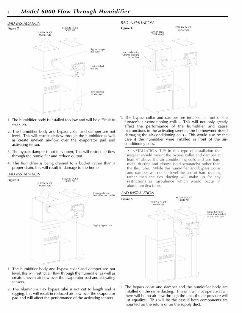
1. The humidifier body is installed too low and will be difficult towork on.
2. The humidifier body and bypass collar and damper are notlevel, This will restrict air-flow through the humidifier as wellas create uneven air-flow over the evaporator pad andactivating sensor.
3. The bypass damper is not fully open, This will restrict air flowthrough the humidifier and reduce output.
4. The humidifier is being drained to a bucket rather than aproper drain, this will result in damage to the home.
1. The humidifier body and bypass collar and damper are notlevel, this will restrict air flow through the humidifier as well ascreate uneven air-flow over the evaporator pad and activatingsensors.
2. The Aluminum Flex bypass tube is not cut to length and issagging, this will result in reduced air-flow over the evaporatorpad and will affect the performance of the activating sensors.
1. The bypass collar and damper are installed in front of thefurnace’s air-conditioning coils – This will not only greatlyaffect the performance of the humidifier and causemalfunctions in the activating sensors, the homeowner riskeddamaging the air-conditioning coils – This would also be thecase if the humidifier were installed in front of the air-conditioning coils.
• INSTALLATION TIP: In this type of installation theinstaller should mount the bypass collar and damper atleast 6" above the air-conditioning coils and use hardmetal ducting and elbows (sold separately) rather thanthe flex tube. While the humidifier and bypass Collarand damper will not be level the use of hard ductingrather than the flex ducting will make up for anyrestrictions or turbulence which would occur inaluminum flex tube.
1. The bypass collar and damper and the humidifier body areinstalled on the same ducting. This unit will not operate at all,there will be no air-flow through the unit, the air pressure willjust equalize. This will be the case if both components aremounted on the return or on the supply duct.
4 Model 6000 Flow Through Humidifier
BAD INSTALLATION
SUPPLY DUCTWARM AIR
RETURN DUCTCOLD AIR
Bypass tube andhumidifier installedon the same duct
BAD INSTALLATION
SUPPLY DUCTWARM AIR
RETURN DUCTCOLD AIR
Air conditioningA-frame blocking
the air flow
BAD INSTALLATION
SUPPLY DUCTWARM AIR
RETURN DUCTCOLD AIR
Bypass collar andhumidifier not parallel
Sagging bypass tube
BAD INSTALLATION
SUPPLY DUCTWARM AIR
RETURN DUCTCOLD AIR
Bypass dampernot open
Unit installedtoo low
Unit drainingto a bucket
Figure 5
Figure 4
Figure 3
Figure 2

1. The humidifier body is not mounted level on the duct, the waterwhich flows to the distribution tray and through the evaporatorpad will all run down one side of the evaporator pad.
2. The bypass collar and tube and humidifier body are notmounted level, this will restrict air flow through the humidifieras well as create uneven air-flow over the evaporator pad andactivating sensors.
3. The bypass tube used is well over the 36" supplied, the flextube is not pulled tight and the most direct route to theopposite duct was not taken, this will restrict air flow throughthe humidifier as well as create uneven air-flow over theevaporator pad and activating sensors
• INSTALLATION TIP: In this type of installation theinstaller should have mounted the bypass collar anddamper in the most convenient location to run ductingback to the unit - If for some reason it was necessary torun ducting like this, hard metal ducting and elbows (soldseparately) rather than the flex tube should be used; Aswell the installer should try to find the most direct routeto duct. While the humidifier and bypass Collar anddamper may be more than the recommended 30" apartthe use of hard ducting rather than the flex ducting willmake up for any restrictions or turbulence which wouldoccur in aluminum flex tube. – Flexible ducting may bethe most convenient for installation purposes howeverwhen it comes to air-flow it is highly restrictive,(see fig 7.)its use should be kept to a minimum and when used itshould be pulled as tight as possible.
PREPARING THE HUMIDIFIERFOR INSTALLATION
Model 6000 humidifiers must be mounted on the return (coldair) duct only. Always ensure that wiring, water supply tube, andwater drainage tube do not come into contact with hot surfacesor sharp edges. Replace any component at the first sign of wear.
CAUTION: When cutting or drilling into ducting take care not todamage any air-conditioning coils or other furnace apparatus
CAUTION: Wear safety glasses and work gloves when installingthis unit; sharp metal edges can cause severe injury.
CAUTION: Turn the furnace off before starting this installation.
STEP #1: RIGHT HAND DUCTING OR LEFT HAND DUCTING
Depending on your furnace, or for the convenience of yourinstallation it may be necessary to convert the humidifier fromright hand ducting or left handing ducting. Follow the stepsbelow to switch the side which the bypass duct will attach to theunit. SWITCH THE DUCTING ONLY IF YOUR APPLICATIONREQUIRES IT.
1. Remove the humidifier front cover – secured in place with a10-24 plastic thumb screw at the bottom of the cover. Tilt thecover away from the body slightly (approx. 1/2") and then liftup the cover to free the hooks at the top of the unit.
2. Remove all loose components packaged inside and anypackaging. With a firm pull, disconnect the water tube from thewater nozzle and remove the evaporator pad assembly by slidingit toward the top of the humidifier, then lifting it out. (fig 8.)
3. Remove the Digital Humidistat Top Console by removing the2 screws which hold it in place. (fig. 9). TAKE CARE NOT TODAMAGE THE HUMIDISTAT SENSOR AT THE END OF THEWIRE EXITING THE BACK OF THE DIGITAL HUMIDISTATTOP CONSOLE.
5Model 6000 Flow Through Humidifier
BAD INSTALLATION
SUPPLY DUCTWARM AIR
RETURN DUCTCOLD AIR
Bypass required ismore than 30" andinstaller is usingflex tube
Unit is not level
Bypass collar andhumidifier not parallel
FLEX PULLED TIGHTEQUIVALENT LENGTH = 2 1/2 FEET
FLEX LOOSEEQUIVALENT LENGTH = 9 FEET
FLEX DUCTING ELBOW (90°) EQUIVALENT LENGTH = 30 FEET
HARD DUCTING ELBOW (90°) EQUIVALENT LENGTH = 10 FEET
Figure 7
Figure 6
Figure 8
Figure 9

4. Gently re-direct the two red wires exiting the right hand sideof the digital humidistat top console so that they exit the topconsole from the left hand side, same side as the two blackwires (fig. 10)
5. Taking care not to pinch any wires and ensuring that thehumidistat sensor wire exits the digital humidistat top consolefrom the “T” slot on the back of the console, replace thehumidistat console onto the top of the humidistat cabinet, andsecure it in place using the two screws removed in step 4.
6. Remove the 2 - #6 screws which hold the humidifier side inplace (a short handled screw driver will give you easier accessto the screws) (fig 11.)
7. Lift the humidifier side out of the right hand position, turn thepart and position it on the other side of the humidifier. (fig. 12)
8. Use the 2 screw removed in step 3 to secure the humidifierside in the left hand side.
STEP #2: MOUNTING THE HUMIDIFIER ON THE DUCT
If you have not already done so remove the humidifier cover –secured in place with a 10-24 plastic thumb screw at the bottomof the cover. Tilt the cover away from the body slightly (approx.1/2") and then lift up the cover to free the hooks at the top of theunit. Remove all loose components packaged inside and anypackaging. With a firm pull, disconnect the water tube from thewater nozzle and remove the evaporator pad assembly by slidingit toward the top of the humidifier, then lifting it out. (fig 8.) – Thehumidifier comes humidifier mounting template – Ensure thecabinet is installed level for proper operation.
Before mounting the Model 6000 humidifier cabinet onto theduct furnace duct, the humidistat sensor, located at the end ofthe wire exiting from the “T” shaped slot on the back of thehumidifier, must be secured in place. This is done be gentlytucking the wire into the “T” slot, hooking the larger tab on thesensor housing into the top of the “T” slot and firmly bringingdown the sensor housing until the smaller tabs on the sensorhousing snap into the sides of the “T” slot (see fig. 13)
CAUTION: When cutting or drilling into ducting take care not todamage any air-conditioning coils or other furnace apparatus
CAUTION: Wear safety glasses and work gloves when installingthis unit. Sharp metal edges can cause severe injury.
1. Use adhesive tape to affix the template onto the duct in theselected location. Use the level line to the template and alevel to ensure the cabinet will be level.
2. Drill the 4 marked cabinet mounting holes on the templateusing a 1/8" drill bit (not supplied)
3. Using a 3/8" drill bit (not supplied) drill a hole inside therectangle marked “HUMIDIFIER CUT OUT”.
4. Using the 3/8" hole drilled in step 3 as a starting point cut outthe Humidifier Cut Out area marked on the template using tinsnips (not supplied). Cut on the outside of the line to ensurea proper fit.
5. Mount the humidifier cabinet on the duct with 4 of the screwsfrom the installation package. Level the humidifier beforetightening the screws. (fig. 14)
6 Model 6000 Flow Through Humidifier
Figure 10
Figure 11
Figure 12
Figure 13

6. Install the evaporator pad assembly by hooking the slanted tabson the Evaporator Pad Frame onto the tabs on the back of thehumidifier cabinet. MAKE SURE THE OPEN END OF THENOZZLE IS FACING YOU.
7. Firmly insert the water tube into the nozzle.
STEP #3: MOUNTING THE BYPASS COLLAR AND DAMPER
The humidifier comes with a Collar and Damper mountingtemplate – If possible ensure that the bypass collar will be level tothe humidifier duct connection. As well try to keep the bypasscollar within 30" of the humidifier.
CAUTION: When cutting or drilling into ducting take care not todamage any air-conditioning coils or other furnace apparatus
CAUTION: Wear safety glasses and work gloves when installingthis unit – Sharp metal edges can cause severe injury.
1. Use adhesive tape to affix the bypass template onto the ductin the selected area.
2. Drill 3 marked bypass collar mounting holes on the templateusing a 1/8" drill bit (not supplied)
3. Using a 3/8" drill by (not supplied) drill a hole inside thecircular area marked Collar Cut Out.
4. Using the 3/8" hole drilled in step 3 as a starting point cut outthe Collar Cut Out area marked on the template using tin snips(not supplied)
5. Mount the bypass collar and damper (fig. 15) using theremaining 3 screws from the installation package. The airdamper should be mounted in the open position. The topscrew secures the damper.
6. Slide one of the 6" springclamps supplied over one endof the bypass tube. Slide thissame end of the bypass tubeover the flange of the collar andsecure it with the spring clamp.
7. Slide the other 6" springclamp over the other end of thebypass tube. Slide this end ofthe bypass tube onto thehumidifier and secure it withthe spring clamp.
8. Ensure the bypass is pulled tight and that any ripples are keptto a minimum and no sagging is occurring, Cut any excessbypass tube off if necessary using tin snips (not supplied).
• INSTALLATION TIP: If replacing an existing humidifierwhich has been installed on your furnace you maybeable use the existing cut outs, however replace thecomponents, bypass collar and damper and bypasstubing. The majority of furnace humidifiers used 6"ducting for bypass. The cutout for the humidifier will,more than likely be different – If replacing a drum stylethe cutout will not be big enough, and if replacing an oldflow through you may have to first install a separatemetal plate (not supplied) to cover the existing hole as itmay be too big – Before you mount the separate metalplate (not supplied) attach the humidifier cabinettemplate to it and drill all necessary holes and make therequired cutouts. Keep in mind the points listed aboveabout length and level of ducting – it maybe best tocover all existing holes and start fresh.
STEP #4: WATER SUPPLY AND DRAINAGE CONNECTION
WARNING: Make sure the evaporator pad is installed correctlyBEFORE you make the water connections.
1. SAND BOTH ENDS (fig 16) of the water supply tube. FAILURETO DO SO MAY RESULT IN LEAKS.
2. Prepare the end (fig 17) of the 1/4" tubing for water connectionto the humidifier (All required hardware supplied in theSaddle Valve Kit in the installation package).
3. Make the tube connection to the humidifier using anadjustable wrench (not supplied) to tighten the nut. (fig 18)
7Model 6000 Flow Through Humidifier
Figure 14
Figure 15
Figure 16
Figure 18
Figure 17
Brass nut Plastic ferroule
Plastic water tube
Brassinsert

4. Select the most convenient location for connecting the selfpiercing needle valve, On a cold water pipe. Connect theneedle valve as shown (fig 19), the hardware shown is suppliedin the needle valve kit. Once the the valve is connected to apipe as shown, TURN THE VALVE CLOSED ALL THE WAY,and then open so water can flow to the humidifier. Check allfittings for leaks and tighten/repair if necessary.
5. YOU MUST RUN A DRAINAGE TUBE FROM THIS UNIT. Selecta convenient location for running the 1/4" drainage tube, 15 ftsupplied. Before you connect the tubing to the drain fitting on thebottom of the unit, slip the 1/4" hose clamp (supplied) over thetubing (fig 20). Push the tubing over the fitting and secure in placewith the hose clamp. CAUTION: Drain tubing must not kink orcome into contact with sharp edges or hot surfaces.
STEP #5: ELECTRICALINSTALLATION
Model 6000 humidifier is equippedwith a digital humidistat built intothe humidifier. This humidistatmonitors the relative humidity levelof the air in your home.
1. Locate the humidifier terminalpanel on the side of the humidifiercabinet, behind the bypass tube.Connect the two red wires fromthe Digital Humidistat TopConsole to the two terminalsmarked “24 VAC IN” (fig 21). Itdoes not matter which wire isconnected to which terminal.
2. Locate the two black wiresfrom the Digital Humidistat TopConsole, connect these wires tothe two wires from the 24 Voltplug in transformer.
3. Use the insulated staplesincluded with your installationpackage to secure any loose wiring.
STEP #6: TESTING THEINSTALLATION
If you have not already replacethe front cover of the humidifierand secure in place using theplastic thumb screw.
1. Make sure all water connections are secure and do not leak. Also,ensure that all components are secure and installed correctly.
2. Plug in the 24 Volt transformer into a constant 120 Volt powersource (an outlet which cannot be shut off via a wall switch).Turn on the humidifier by depressing the main red ON/OFFbutton – When the unit is powered the main green LED on theDigital Humidistat Top Console will turn ON. (fig. 22)
3. Set the digital humidistat to a setting of 50% + , This ensuresthe humidistat is calling for humidity – If the digital humidistatis not calling for humidity at the BEGINNING of the furnacecycle the humidifier will not turn on, if you turn up the digitalhumidistat in the middle of the furnace cycle the humidifierwill wait until the NEXT cycle to turn on. SEE SECTIONSETTING and OPERATING THE DIGITAL HUMIDISTAT.
4. Turn on the power to your furnace and turn up the thermostatso that the furnace cycles on in heating mode.
• OPERATING TIP: Most furnaces will take a fewminutes to allow heat to build up before the furnace fanwill run – The “HUMIDISENSE” control contained in thehumidifier will wait until it senses your furnace fanblowing hot air. If only your furnace fan is running theunit should not turn on. The “HUMIDISENSE” will notturn the humidifier on until is senses a temperature riseof 4°C and the air temperature is over 30°C. Thisensures the efficient use of water.
5. Depending on your furnace type the unit should turn onwithin approx 60 seconds of the furnace entering theHEATING cycle. You will know because the green“HUMIDISENSE” LED on the front of unit will turn on (fig 23.)– If the unit does not turn on refer to the trouble shootingsection in the Maintenance Guide.
8 Model 6000 Flow Through Humidifier
Figure 19Brass nut
Plasticferroule
Plastic water tube
Brass insert
Figure 20
Figure 21
Figure 22Main PowerGreen LED
Figure 23
GreenHumidisense
LED

6. Once the unit has been running for approx 3-4 minutes youwill see a small amount of water trickling out of the drain tube.If the unit has turned on and the green light is on but no wateris trickling refer to the trouble shooting section in theMaintenance Guide.
• OPERATING TIP: In order to ensure efficient water use,ensure water will not blow off the evaporator, and toprotect the humidifier’s solenoid valve there is an orificefitting installed on the inlet of the solenoid valve. Thisfitting restricts the amount of water flowing to the unit,which will vary depending on your house’s water pressure– On average this fitting will allow approx 300-600 ml ofwater to flow in 5 minutes of humidifier operation.
7. After about 5 minutes of running turn your thermostat downso the furnace cycles off. IT IS IMPORTANT TO ALLOW THEFURNACE TO CYCLE OFF VIA THE THERMOSTAT AND NOTTHE MAIN FURNACE SWITCH – AS ALL FURNACES WILLRUN A COOL DOWN TO ALLOW HEAT TO CIRCULATEOUT OF THE FURNACE HEATING CHAMBER. TheHumidifier will sense the temperature drop and shut off (thiswill occur depending on your furnace, from 60 seconds beforethe furnace shuts of to 60 seconds after the furnace shuts off.)You will know the humidifier has shut off because the green“HUMIDISENSE” LED on the front of the humidifier will shutoff. (fig. 23) – The off cycle of the “HUMIDISENSE”CONTROL IS ADJUSTABLE – See section “CUSTOMIZINGHUMIDISENSE TO YOUR FURNACE” below if the humidifierdoes not shut off with your furnace.
• OPERATING TIP: Most furnaces will take anywherefrom 30 seconds to 2 minutes to complete a off cycle.First the furnace will sense that the thermostat is satisfiedthen the furnace burner will shut off. The furnace fanwill continue to run (the amount of time depending onhow your furnace is set up) this allows the heat tocirculate out of the furnace heating chamber and assuresefficient use of heating fuel.
HUMIDIFIER OPERATION
CUSTOMIZING HUMIDISENSE TO YOUR FURNACE
The HUMIDISENSE control is a temperature and time basedcontrol designed to cycle the humidifier ON and OFF insequence with your furnace’s cycles. As there are many differenthomes and styles of furnaces the HUMIDISENSE control has 4self contained adjustable temperature set points to control thehumidifier’s cycles, as well there is a redundant safety circuitwhich with the use of a pressure switch (sold separately) can beused to bypass the temperature control feature and cycle thehumidifier based on the furnace fan’s cycle.
Depending on your furnace or other factors present in yourhome (use of secondary supplemental heating, HVR’s, ERV’s,etc) it may become necessary to change the setting of thecontrol to ensure the humidifier is shutting off when yourfurnace cycles off. This is easily done by changing the dip switch(located on the lower side of the control housing see below)positions, using a small screw driver. NOTE: Only change thesetting IF REQUIRED.
YOU MUST CAREFULLY FOLLOW THE FOLLOWING STEPS TOCHANGE THE CONTROL’S SET POINT:
1. Determine if the humidifier is not shutting off when thefurnace shuts off
2. Read the explanation of the different settings below anddetermine which dip switch position you require.
3. The humidifier must be energized but NOT running in orderto change the dip switch position. If your humidifier has notshut off after a furnace cycle, turn DOWN the furnace’sthermostat (so the furnace shuts off and will not come backon). UNPLUG the humidifier for a few minutes and allow thehumidifier to cool down, then plug the humidifier back in.Now the humidifier should be plugged IN, the humidistatturned UP all the way, your furnace should be OFF, and thehumidifier should NOT be running.
4. With the furnace OFF, Change the dip switch position to thedesired location.
5. AFTER you have changed the dip switch location UNPLUGTHE HUMIDIFIER FOR 1 MINUTE.
6. After the humidifier has been unplugged for 1 MINUTE, Plugthe humidifier back in and WAIT ANOTHER MINUTE.
7. The control set point has now been changed. Turn UP thefurnace thermostat and check humidifier operation.
HUMIDISENSE CONTROL SETTINGS: FACTORY SETTING (FIG. 25.)
The control comes from the factory setwith the criteria indicated below.
Humidifier ON : A temperature rise of 4°Cin one minute and a temperature greaterthan 30°C
Humidifier OFF: A temperature drop of2°C in one minute and a temperature lessthan 45°C
• This setting will meet the requirement of 85% of the furnacesin the market today. It will provide the required humidifiercontrol on furnaces ranging from high to low efficiency. Youshould only change the setting if required.
9Model 6000 Flow Through Humidifier
Dip Switch
Figure 25
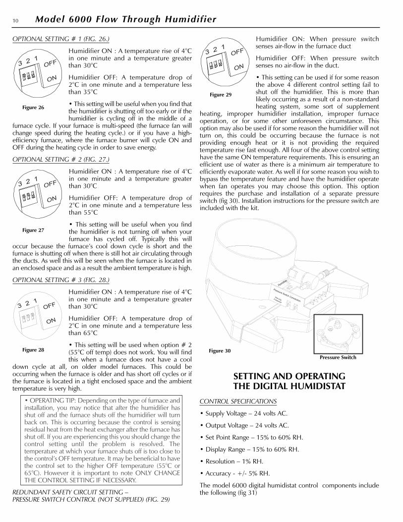
OPTIONAL SETTING # 1 (FIG. 26.)
Humidifier ON : A temperature rise of 4°Cin one minute and a temperature greaterthan 30°C
Humidifier OFF: A temperature drop of2°C in one minute and a temperature lessthan 35°C
• This setting will be useful when you find thatthe humidifier is shutting off too early or if thehumidifier is cycling off in the middle of a
furnace cycle. If your furnace is multi-speed (the furnace fan willchange speed during the heating cycle.) or if you have a high-efficiency furnace, where the furnace burner will cycle ON andOFF during the heating cycle in order to save energy.
OPTIONAL SETTING # 2 (FIG. 27.)
Humidifier ON : A temperature rise of 4°Cin one minute and a temperature greaterthan 30°C
Humidifier OFF: A temperature drop of2°C in one minute and a temperature lessthan 55°C
• This setting will be useful when you findthe humidifier is not turning off when yourfurnace has cycled off. Typically this will
occur because the furnace’s cool down cycle is short and thefurnace is shutting off when there is still hot air circulating throughthe ducts. As well this will be seen when the furnace is located inan enclosed space and as a result the ambient temperature is high.
OPTIONAL SETTING # 3 (FIG. 28.)
Humidifier ON : A temperature rise of 4°Cin one minute and a temperature greaterthan 30°C
Humidifier OFF: A temperature drop of2°C in one minute and a temperature lessthan 65°C
• This setting will be used when option # 2(55°C off temp) does not work. You will findthis when a furnace does not have a cool
down cycle at all, on older model furnaces. This could beoccurring when the furnace is older and has short off cycles or ifthe furnace is located in a tight enclosed space and the ambienttemperature is very high.
• OPERATING TIP: Depending on the type of furnace andinstallation, you may notice that after the humidifier hasshut off and the furnace shuts off the humidifier will turnback on. This is occurring because the control is sensingresidual heat from the heat exchanger after the furnace hasshut off. If you are experiencing this you should change thecontrol setting until the problem is resolved. Thetemperature at which your furnace shuts off is too close tothe control’s OFF temperature. It may be beneficial to havethe control set to the higher OFF temperature (55°C or65°C). However it is important to note ONLY CHANGETHE CONTROL SETTING IF NECESSARY.
REDUNDANT SAFETY CIRCUIT SETTING – PRESSURE SWITCH CONTROL (NOT SUPPLIED) (FIG. 29)
Humidifier ON: When pressure switchsenses air-flow in the furnace duct
Humidifier OFF: When pressure switchsenses no air-flow in the duct.
• This setting can be used if for some reasonthe above 4 different control setting fail toshut off the humidifier. This is more thanlikely occurring as a result of a non-standardheating system, some sort of supplement
heating, improper humidifier installation, improper furnaceoperation, or for some other unforeseen circumstance. Thisoption may also be used if for some reason the humidifier will notturn on, this could be occurring because the furnace is notproviding enough heat or it is not providing the requiredtemperature rise fast enough. All four of the above control settinghave the same ON temperature requirements. This is ensuring anefficient use of water as there is a minimum air temperature toefficiently evaporate water. As well if for some reason you wish tobypass the temperature feature and have the humidifier operatewhen fan operates you may choose this option. This optionrequires the purchase and installation of a separate pressureswitch (fig 30). Installation instructions for the pressure switch areincluded with the kit.
SETTING AND OPERATING THE DIGITAL HUMIDISTAT
CONTROL SPECIFICATIONS
• Supply Voltage – 24 volts AC.
• Output Voltage – 24 volts AC.
• Set Point Range – 15% to 60% RH.
• Display Range – 15% to 60% RH.
• Resolution – 1% RH.
• Accuracy - +/- 5% RH.
The model 6000 digital humidistat control components includethe following (fig 31)
10 Model 6000 Flow Through Humidifier
Figure 26
Figure 27
Figure 29
Figure 28 Figure 30Pressure Switch

1. MAIN ON/OFF POWER BUTTON FOR THE HUMIDIFIER. –Use this button only when turning ON or OFF the humidifier.
2. REDUCE RELATIVE HUMIDITY SET POINT BUTTON. – Usethis button only when reducing the relative humidity set point.
3. INCREASE RELATIVE HUMIDITY SET POINT BUTTON. – Usethis button only when increasing the relative humidity set point.
4. DIGITAL DISPLAY. – Displays (fig 32) a) User Set Point. b) SetPoint Number Indication. c) Humidifier Operating Indication.d) Actual relative humidity being sensed. e) Incremental barindicating relative humidity status as it relates to the set point.
5. MAIN POWER GREEN LED. – Indicates that the main powerto the humidifier is ON.
When power is first turned on to the humidifier the digitalhumidistat will display the default set point, which is 35%. Youmay change this setting by using the Increase or Decrease buttonon the control. If for some reason the power is lost to thehumidifier (power outage or unit becomes unplugged) there is adelay (30 sec to 1 min) before the control loses it’s set point,however if power is lost for any length of time the control willrevert to the default settings. If you notice that the control isconsistently resetting to the set point this is an indication that, a)You have not wired (or plugged in the transformer) thetransformer to a CONSTANT 120 volt supply (one which cannotbe shut off via a switch) or b) The power connections (Two BlackWires) to the humidifier are loose.
What is displayed will depend on what the set point is, what therelative humidity being sensed is, and if the set point is beingchanged.
DIGITAL DISPLAY WHEN CHANGING THE HUMIDITY LEVEL (FIG 33)
When you start to change the set point (raising or lowering) thedisplay will change, showing two numbers and a pointing finger(the water droplets may be displayed as well depending on whatthe relative humidity status was before you started changing theset point). The number displayed beside the pointing finger is theset point and is the number you are changing – The larger
number on the left of the display is the actual relative humiditybeing sensed.
DIGITAL DISPLAY WHEN HUMIDIFIER HAS REACHED THE SETPOINT (FIG 34)
When the relative humidity being sensed raises above the setpoint the humidifier does not need to run and the control displaywill be similar to above – It will show two numbers and a pointingfinger. The number displayed beside the pointing finger is the setpoint – The larger number on the left of the display is the actualrelative humidity being sensed.
DIGITAL DISPLAY WHEN HUMIDIFIER IS HUMIDIFYING. (FIG 35)
When the humidifier is adding moisture to air the display willchange – In the top right of the display will be a number, this isthe set point. - In the mid lower section of the display will bewater droplets, this is indicating that the humidifier is addingmoisture. - The remaining portion of the display will be taken upby a slanted incremental bar, This bar represents the percentageof the set point achieved.
SLANTED INCREMENTAL BAR.
When humidifying the control will display the set point and a barrepresenting the percentage of set point achieved – each barrepresent approximately 10% of the set point. Below are a fewexamples of humidifying displays showing a set point, anincremental bar, and what relative humidity they represent.
1. Set point 40% - 50% of bars showing - relative humidity 20%
2. Set point 45% - 80% of bars showing – relative humidity 36%
3. Set point 50% - 50% of bars showing – relative humidity 25%
CONTROLLING THE HUMIDITY LEVELAND HUMIDIFIER OPERATION
HUMIDIFIER START UP.
When you first plug in the 24 Volt transformer and turn on yourhumidifier you may hear a click. This is the power getting to thecontrol’s relay – As well if you adjust the digital humidistat UP orDOWN and past the sensed humidity level you may hear thecontrol’s relay clicking. This is normal as the humidistat is just anON/OFF switch, every time the digital humidistat is turnedDOWN the power is cut to the HUMIDISENSE control.
When starting up the humidifier for operation:
1. Make sure the transformer is plugged in and the water supplyis turned on.
2. Make sure main power to the humidifier is turned ON.
3. Turn the humidistat up high, so it is calling for humidity.
4. Turn your furnace thermostat UP so the furnace cycles ON.
5. Once the HUMIDISENSE control senses heat the humidifier willturn ON. You will know because the green “HUMIDISENSE”LED (fig. 23) on the front of the humidifier will turn ON.
6. After a few moments you should hear water trickling throughthe drain.
7. After your furnace has complete the heating cycle and shut off
11Model 6000 Flow Through Humidifier
Figure 31
Slanted Incremental Bar
Figure 32
Figure 33
Figure 34
Figure 35
(by the thermostat) the humidifier will cycle OFF – You willknow because the green “HUMIDISENSE” LED (fig. 23) on thefront of the humidifier will turn OFF.
CONTROLLING THE HUMIDITY LEVEL
The digital humidistat with this humidifier is to control the amountof moisture added to the air in your home – It will sense the relativehumidity level in the air and work as an ON/OFF switch to controlthe humidifier, regardless of whether your furnace is on or not.
At the beginning of the heating season it may take sometime tobuild up the relative humidity level in your home to the desiredlevel – For the first few weeks turn the humidistat up high to ensurethe humidifier will turn on with every furnace cycle – after you feelthat you have achieved the desired relative humidity level turn thehumidistat down until it cycles the humidifier OFF. The Humidifierwill then work to maintain the relative humidity at that level.
ACHIEVING AND MAINTAINING A HUMIDITY LEVEL
Outside conditions are the primary factor affecting the humidity levelin your home. The colder it gets outside the less moisture the outsideair will have, your home brings in that outside air and the humidifierwill work to add moisture to it. As outside conditions change thehumidity level in your home will change as well. Other factorswhich will affect humidity levels in the home include, how many air-changes are occurring, the amount of people occupying the home,air leaks, the use of showers, exhaust fans, HRV’s, and the use of afireplaces or wood stoves. For more information on achieving ahumidity level and or maximizing the output of the humidifier pleasesee the Maintenance and Trouble Shooting Guide.
SAFELY OPERATING A FURNACE HUMIDIFIER
Proper control of the relative humidity level in the home is key toensuring good IAQ (Indoor Air Quality) for your home as well asprotecting against moisture damage.
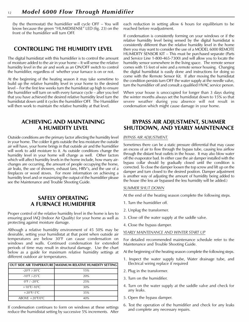
Although a relative humidity environment of 45 50% may bedesirable, setting your humidistat at that point when outside airtemperatures are below 30°F can cause condensation onwindows and walls. Continued condensation for extendedperiods of time may result in structural damage. Use the chartbelow as a guide for maximum relative humidity settings atdifferent outdoor air temperatures.
If condensation continues to form on windows at these settingsreduce the humidistat setting by successive 5% increments. After
each reduction in setting allow 6 hours for equilibrium to bereached before readjustment.
If condensation is consistently forming on your windows or if therelative humidity level being sensed by the digital humidistat isconsistently different than the relative humidity level in the homethen you may want to consider the use of a MODEL 6000 REMOTEHUMIDITY SENSOR KIT – This must be purchased separate (Partsand Service Line 1-800-465-7300) and will allow you to locate thehumidity sensor somewhere in the living space. The remote sensorcomes with 15 feet of wire and a remote sensor housing. Changingthe digital humidistat is easily done and instructions for doing socome with the Remote Sensor Kit. If after moving the humidistatthe condition persists turn OFF the water supply at the needle valve,turn the humidifier off and consult a qualified HVAC service person.
When your house is unoccupied for longer than 3 days duringthe winter months always set the humidistat down to 15% so thatsevere weather during you absence will not result incondensation which might cause damage in your home.
BYPASS AIR ADJUSTMENT, SUMMERSHUTDOWN, AND YEARLY MAINTENANCE
BYPASS AIR ADJUSTMENT.
Sometimes there can be a static pressure differential that may causean excess of air to flow through the bypass tube, causing less airflowthrough the distant heat outlets in the house. It may also blow wateroff the evaporator bad. In either case the air damper installed with thebypass collar should by gradually closed until the condition iscorrected. To close the damper loosen the top screw and lift up on thedamper and turn closed to the desired position. Damper adjustmentis another way of adjusting the amount of humidity being added tothe house (the less air bypassed the less humidity will be added.)
SUMMER SHUT DOWN
At the end of the heating season complete the following steps.
1. Turn the humidifier off.
2. Unplug the transformer.
3. Close off the water supply at the saddle valve.
4. Close the bypass damper.
YEARLY MAINTENANCE AND WINTER START UP
For detailed recommended maintenance schedule refer to theMaintenance and Trouble Shooting Guide.
At the beginning of the heating season complete the following steps.
1. Inspect the water supply tube, Water drainage tube, andElectrical wiring replace if required
2. Plug in the transformer.
3. Turn on the humidifier.
4. Turn on the water supply at the saddle valve and check forany leaks.
5. Open the bypass damper.
6. Test the operation of the humidifier and check for any leaksand complete any necessary repairs.
OUT SIDE AIR TEMPERATURE MAXIMUM RELATIVE HUMIDITY SETTING
-20°F /-30°C 15%
-10°F /-25°C 20%
0°F / -20°C 25%
+10°F/-10°C 30%
+20°F/-5°C 35%
ABOVE +20°F/0°C 40%
12 Model 6000 Flow Through Humidifier