fusion technology institute department of engineering physics, university of wisconsin-madison ins 1...
Post on 21-Dec-2015
214 views
TRANSCRIPT

1Fusion Technology InstituteDepartment of Engineering Physics, University of Wisconsin-Madison INS
Solid Wall Recirculating Blanket: Geometry,
Materials Compatibility, Structural Evaluation,
Fabrication and Fluid Circuits
I.N. Sviatoslavsky*, M. Sawan*, E.A. Mogahed*, S. Majumdar, R. Mattas, S. Malang, P.J. Fogarty, M. Friend, C. Wong
*University of Wisconsin, Madison, WI 53706
APEX Quarterly MeetingGrand Canyon, AZApril 7-10, 2003
2Fusion Technology InstituteDepartment of Engineering Physics, University of Wisconsin-Madison INS
Layout and Geometry of Recirculating Blanket
• Geometric layout of the reactor torus is patterned after ARIES-AT with changes in minor and major radii, neutron wall loading and surface heating.
• The structure is nano-composited ferritic steel and the coolant is low viscosity FLIBE (Li2BeF4) formulation.
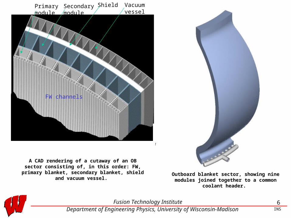
• Outboard blanket (OB) is 30 cm deep, followed by a secondary blanket 40 cm thick, then a shield, 10 cm thick and finally, a vacuum vessel 30 cm thick. The primary OB blanket is banana shaped, 30 cm wide at the mid-plane tapering to 23 cm at the upper and lower extremities. The overall height is 8 m.
• The inboard blanket (IB) is straight and uniform in cross section. There is no secondary IB blanket. It is 30 cm thick, and is followed by a shield 40 cm thick and then, a vacuum vessel 30 cm deep. The overall height is ~7.7 m.
3Fusion Technology InstituteDepartment of Engineering Physics, University of Wisconsin-Madison INS
Geometry of the OB Blanket Module/Sector
• Each OB blanket module has 5 FW U bend channels traversing the blanket from top to bottom. Each FW channel has a smaller tube running along its length. This tube will contain molten Pb as a neutron multiplier.
• The rear side of the primary OB blanket module is a near square box, with rectangular channels attached to the side and back walls.
• The Flibe coolant enters the module on the bottom, travels up through the FW channels and at the top splits into two streams:
1. One stream (~2/3 of the mass flow) returns down through the side and back channels of the square box.
2. The second stream (~1/3 of the mass flow) returns through the large central channel in the square box.
• Nine modules stacked toroidally constitute a sector. A sector is a unit that can be removed unilaterally for reactor maintenance. There are 16 sectors in the reactor.
4Fusion Technology InstituteDepartment of Engineering Physics, University of Wisconsin-Madison INS
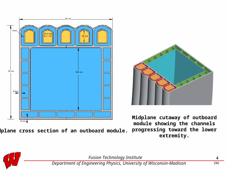
Midplane cross section of an outboard module.
Midplane cutaway of outboard module showing the channels progressing
toward the lower extremity.
5Fusion Technology InstituteDepartment of Engineering Physics, University of Wisconsin-Madison INS
Geometry of the IB Blanket Module/Sector
• The IB blanket modules are identical to the OB in regards to the coolant flow. However, instead of banana shaped, they are straight and of uniform cross section top to bottom. There are also Pb tubes of neutron multiplier on the IB side.
• Five IB modules stacked toroidally make up a sector. Both IB and OB sectors are mounted on a common skid for retracting it from the torus, passing between the outboard legs of the TF coils.
6Fusion Technology InstituteDepartment of Engineering Physics, University of Wisconsin-Madison INS
A CAD rendering of a cutaway of an OB sector consisting of, in this order: FW, primary blanket, secondary blanket,
shield and vacuum vessel. Outboard blanket sector, showing nine modules joined together to a common coolant header.
FW channels
Primarymodule
Secondarymodule
Shield Vacuumvessel

7Fusion Technology InstituteDepartment of Engineering Physics, University of Wisconsin-Madison INS
Inboard Blanket plusPrimary O.B. Blanket
Inboard BlanketInboard Blanket plus
Primary and SecondaryO.B. Blanket

8Fusion Technology InstituteDepartment of Engineering Physics, University of Wisconsin-Madison INS
Inboard / Outboard Blanketswith Shield Module
Inboard / Outboard Blankets,Shield Module, and Vacuum Vessel

9Fusion Technology InstituteDepartment of Engineering Physics, University of Wisconsin-Madison INS
Structural Material
• A relatively new structural material has been investigated in recent years as potentially attractive for fusion energy. Ferrritic/martensitic steels have always been considered attractive for fusion, but the operating temperature for them was limited to 550-600oC.
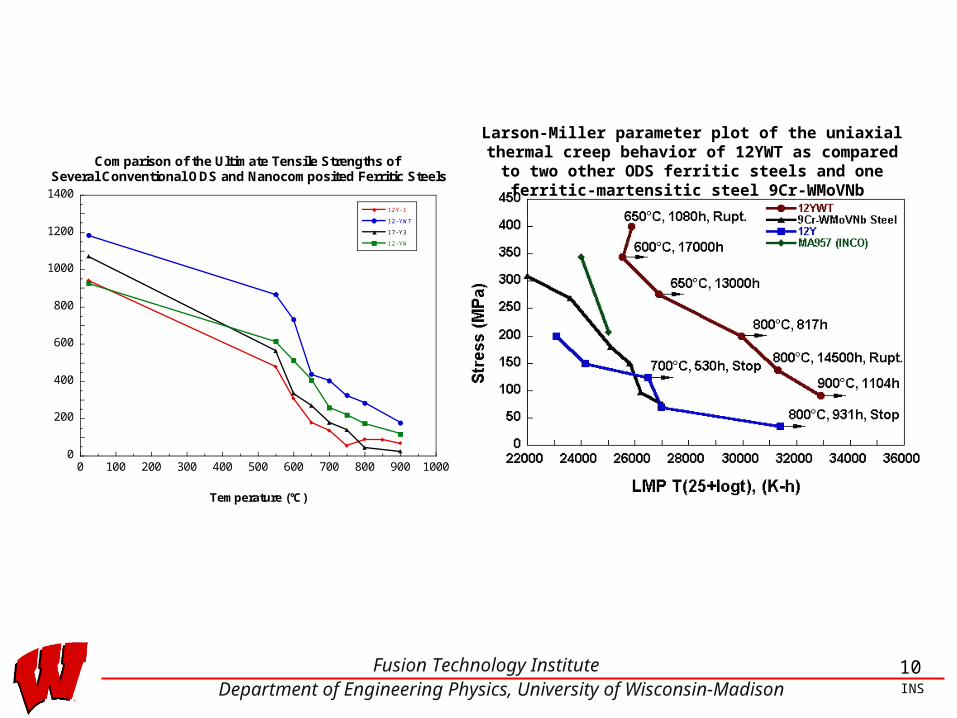
• Nano-composited ferritic steels contain a high density of small particles of Y2O3 or TiO2 dispersed in the ferritic matrix. One such material developed by ORNL is 12 YWT and sometimes called oxide dispersion strengthened (ODS).
• 12 YWT has superior high temperature characteristics. An upper temperature limit of 800oC and compatibility with Flibe up to 700oC.
10Fusion Technology InstituteDepartment of Engineering Physics, University of Wisconsin-Madison INS
0
200
400
600
800
1000
1200
1400
0 100 200 300 400 500 600 700 800 900 1000
Comparison of the Ultimate Tensile Strengths of Several Conventional ODS and Nanocomposited Ferritic Steels
12Y- 1
12- YWT
17- Y3
12- YW
Ultimate Tensile Strength (MPa)
Temperature (°C)
Larson-Miller parameter plot of the uniaxial thermal creep behavior of 12YWT as compared to two other ODS ferritic
steels and one ferritic-martensitic steel 9Cr-WMoVNb

11Fusion Technology InstituteDepartment of Engineering Physics, University of Wisconsin-Madison INS
B
B
B
B
B
B
B
B
J
J
J
JJ
JJ J
0
50
100
150
200
250
300
350
500 550 600 650 700 750 800 850 900Tempaerature (C)
B 12YWT
J MA957 B
B
B
B
B
B
B
B
J
J
J
JJ
J J J0
50
100
150
200
250
500 550 600 650 700 750 800 850 900Temperature (C)
B St 12YWT
J St MA957
Calculated creep rupture stress for MA957 and 12YWT for 2 year lifetime
Calculated allowable time dependent stress intensity for MA957 and 12YWT
based upon 2/3 of the creep rupture stress
12Fusion Technology InstituteDepartment of Engineering Physics, University of Wisconsin-Madison INS
Materials Compatibility
• The main compatibility issue for the recirculating blanket was
“ferritic steel with Pb.”
There is a lot of data available from ORNL, INEEL and from Russia. This issue has been settled from Russian experiments which show that static tests with strict O2 control show acceptable corrosion results at 700oC. Furthermore, a thin plating of W on the inside of tubes can be deposited, if this becomes necessary.
• ORNL has set the compatibility of ferritic steel with Flibe at 700oC. Information from S. Zinkle.
13Fusion Technology InstituteDepartment of Engineering Physics, University of Wisconsin-Madison INS
Stress Analysis (S. Majumdar-ANL)
• Heat conduction and elastic stress analyses were carried out by using the finite element program ABAQUS. Unit-poloidal-thickness slices at the bottom, mid-plane and top of the module were analyzed. No heat conduction was assumed in the poloidal direction. The stress analysis was conducted with the generalized plane strain assumption.
• The primary stress limits for the membrane (Pm and PL) and bending (Pb) are as follows:
⊇
Pm ≤Sm at thickness- averaged temperature St at thickness- averaged temperature and design life
€
PL + Pb ≤KSm
€
PL +PbK t
≤St
where K is the bending shape factor (=1.5) and Kt = (K+1)/2.
and
e
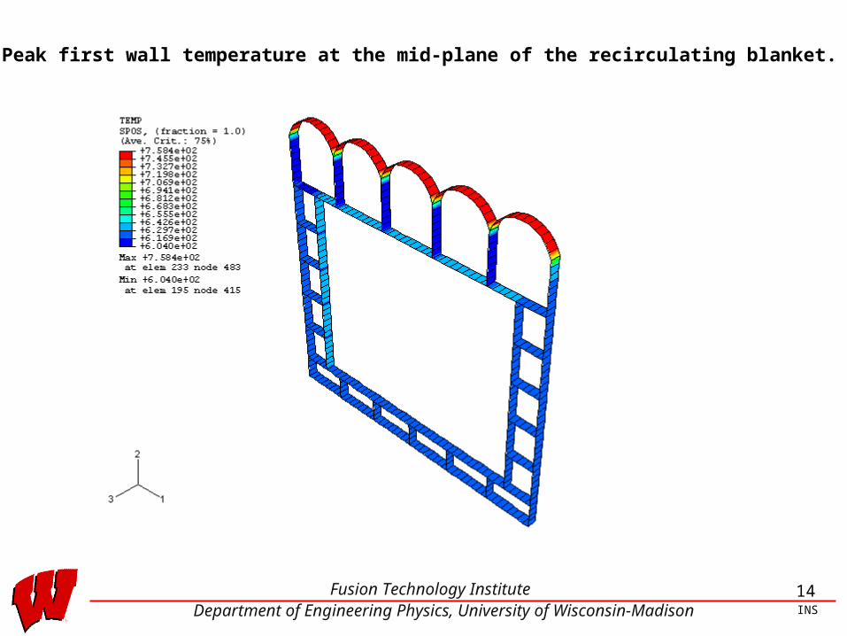
14Fusion Technology InstituteDepartment of Engineering Physics, University of Wisconsin-Madison INS
Peak first wall temperature at the mid-plane of the recirculating blanket.

15Fusion Technology InstituteDepartment of Engineering Physics, University of Wisconsin-Madison INS
Primary membrane plus bending stressdistribution at the bottom of the recirculating blanket.

16Fusion Technology InstituteDepartment of Engineering Physics, University of Wisconsin-Madison INS
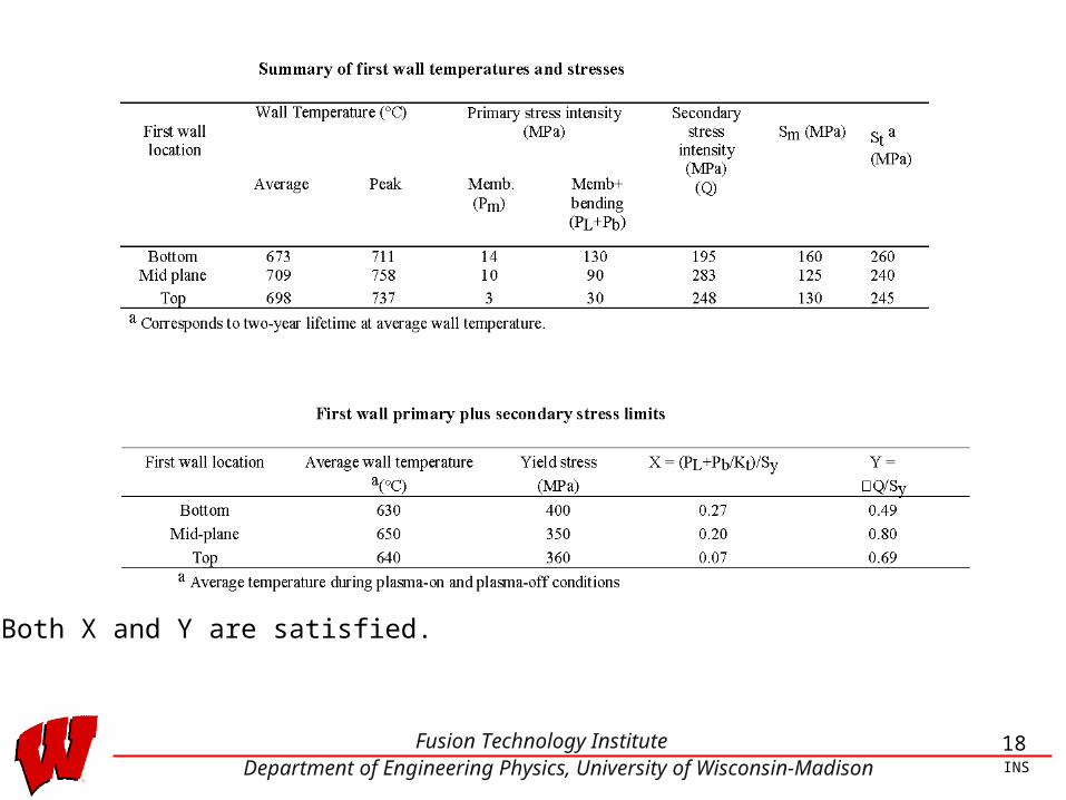
Thermal Stress and Cyclic Ratcheting
Primary plus secondary stress limit for cyclic ratcheting is the Test A2 of the
ITER Structural Design Criteria (ISDC) which is as follows:
X + Y 1
where
Sy is the average temperature of the section during the secondary stress cycle, i.e.
during plasma-on and plasma-off conditions, and Q is the secondary stress
intensity range during the cycle.
€
X =PL + Pb / K t
Sy
€
Y =ΔQSy
,
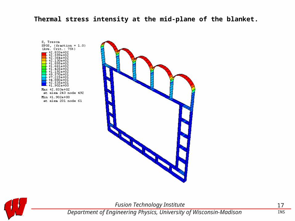
17Fusion Technology InstituteDepartment of Engineering Physics, University of Wisconsin-Madison INS
Thermal stress intensity at the mid-plane of the blanket.
18Fusion Technology InstituteDepartment of Engineering Physics, University of Wisconsin-Madison INS
•Both X and Y are satisfied.
19Fusion Technology InstituteDepartment of Engineering Physics, University of Wisconsin-Madison INS
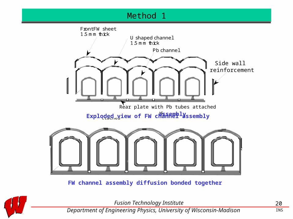
Fabrication
• A major disadvantage of ODS steel is joining. The only method that has produced acceptable joints is diffusion bonding or hipping. Conventional joining such as TiG or MiG, or plasma produces inferior welds and cannot be used for joints where structural integrity is paramount.
• Fabrication of the FW and blanket assembly utilizes preliminary conventional welding to achieve closure for sealing and then is followed by diffusion bonding.
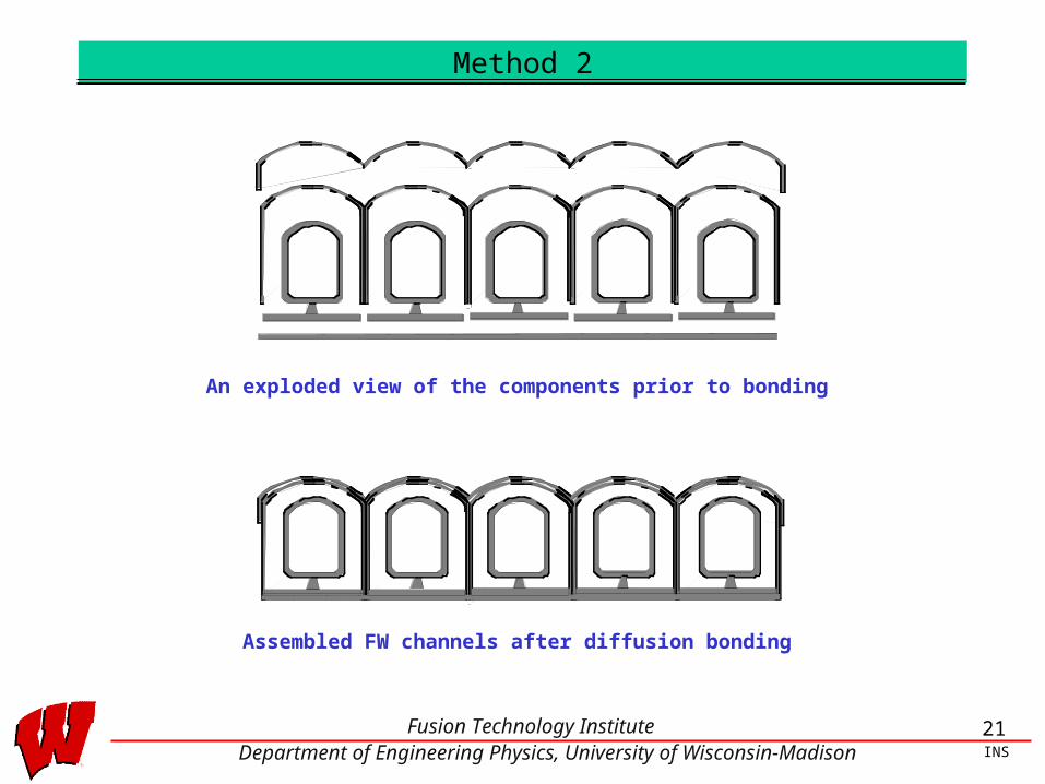
• Two methods have been proposed for the assembly of the FW channels.
20Fusion Technology InstituteDepartment of Engineering Physics, University of Wisconsin-Madison INS
Method 1
U shaped channel 1.5 mm thick
Pb channel
Side wall reinforcement
Front FW sheet 1.5 mm thick
Exploded view of FW channel assembly
FW channel assembly diffusion bonded together
Rear plate with Pb tubes attached
Rear plate with Pb tubes attached
Exploded view of FW channel assembly
Side wall reinforcement
21Fusion Technology InstituteDepartment of Engineering Physics, University of Wisconsin-Madison INS
Method 2
An exploded view of the components prior to bonding
Assembled FW channels after diffusion bonding
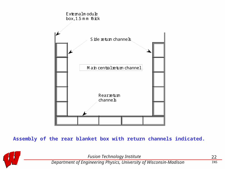
22Fusion Technology InstituteDepartment of Engineering Physics, University of Wisconsin-Madison INS
External module box, 1.5 mm thick
Side return channels
Rear return channels
Main central return channelMain central return channel
Assembly of the rear blanket box with return channels indicated.

23Fusion Technology InstituteDepartment of Engineering Physics, University of Wisconsin-Madison INS
Complete assembly of outboard blanket module. The units are coupled and diffusion bonded together to form a single module.
24Fusion Technology InstituteDepartment of Engineering Physics, University of Wisconsin-Madison INS
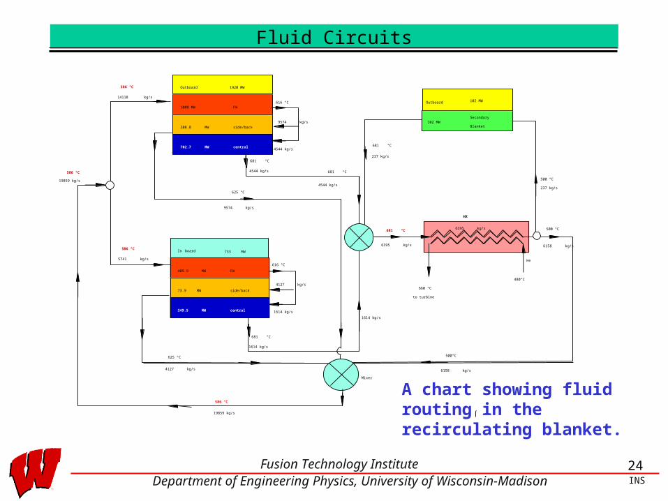
Fluid Circuits
A chart showing fluid routing in the recirculating blanket.
1008 MW FW
208.8 MW
702.7 MW
side/back
central
409.9 MW FW
73.9 MW
249.5 MW
side/back
central
Outboard
In board
4544 kg/s
625 °C
625 °C
681 °C
102 MWSecondary
Blanket
681 °C
616 °C
6395 kg/s
19859 kg/s
Mixer
He
480°C
660 °C
HX
500 °C
500°C
Outboard
to turbine
1614 kg/s
4544 kg/s
237 kg/s
681 °C
500 °C
6158 kg/s
14118 kg/s
5741 kg/s
19859 kg/s
586 °C
4544 kg/s
681 °C
586 °C
237 kg/s
6395 kg/s
681 °C
616 °C
9574 kg/s
1614 kg/s
1614 kg/s
6158 kg/s
4127 kg/s
586 °C
4127 kg/s
9574 kg/s
1920 MW
733 MW
102 MW
586 °C

25Fusion Technology InstituteDepartment of Engineering Physics, University of Wisconsin-Madison INS
Fluid Circuits (contd.)
• Each module has three Flibe connections
1. Supply line
2. Return line from side and back channels
3. Return line from the rear main central channel
• These connections are made through a triplex tube, that is, three concentric tubes with a common axis
1. The outermost tube is the cool fluid supply2. The next is the return from the rear side and back channels3. The innermost tube is the hot return from the rear main central channel
• There are three good reasons for using a triplex tube:
1. Saves on heat losses
2. Reduces tritium diffusion out of the tubes to the environment
3. Only one tube (outermost) needs to be severed. The other connections are slip joints and can tolerate minor leakage.
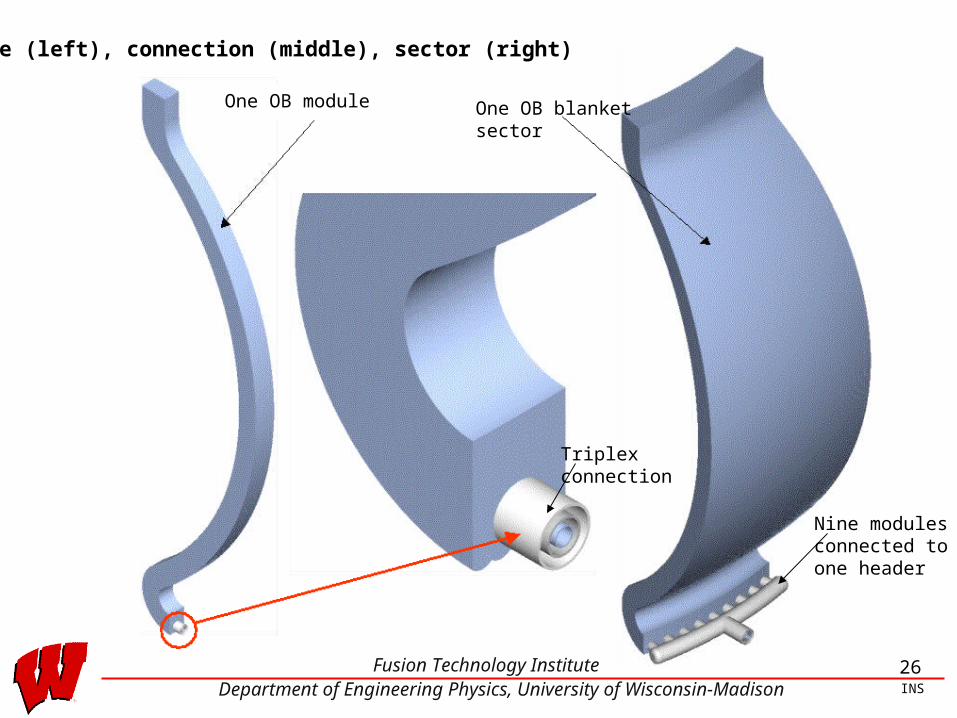
26Fusion Technology InstituteDepartment of Engineering Physics, University of Wisconsin-Madison INS
Module (left), connection (middle), sector (right)
One OB blanketsector
One OB module
Triplexconnection
Nine modulesconnected toone header
27Fusion Technology InstituteDepartment of Engineering Physics, University of Wisconsin-Madison INS
Conclusions
• Utilizing ODS ferritic steel 12YWT with Flibe as a coolant and Pb as neutron
multipler appears to make a good combination for an advanced high
temperature blanket which can operate at a high efficiency with a He gas
Brayton cycle
• Even though the recirculating blanket is somewhat complicated, its forward
looking aims, that of maximizing nuclear parameters to achieve a high
conversion efficiency, are well worth striving for.