future circular collider study fcc-he baseline parameters
TRANSCRIPT

EDMS 17979910 FCC-ACC-RPT-0012 V1.0, 6 April, 2017
Future Circular Collider Study
FCC-he Baseline Parameters
Oliver Bruning1, John Jowett1, Max Klein2,Dario Pellegrini1, Daniel Schulte1, Frank Zimmermann1
1 CERN, 2 University of Liverpool
Abstract
Initial considerations are presented on the FCC-he, the electron-hadron colliderconfiguration within the Future Circular Collider study. This note considers argu-ments for the choice of the electron beam energy based on physics, ep scatteringkinematics and cost. The default configuration for the electron accelerator, as forthe LHeC, is chosen to be a multi-turn energy recovery linac external to the pro-ton beam tunnel. The main accelerator parameters of the FCC-he are discussed,assuming the concurrent operation of ep with the 100 TeV cms energy pp collider.These are compared with the LHeC design concept, for increased performance asfor a Higgs facility using the HL-LHC, and also the high energy HE-LHC ep colliderconfiguration. Initial estimates are also provided for the luminosity performance ofelectron-ion colliders for the 60 GeV electron ERL when combined with the LHC,the HE-LHC and the FCC ion beams.
1 Introduction
Since the discovery of quarks in electron-proton scattering [1, 2], using the 2 mile electronlinac at Stanford in 1968, deep inelastic scattering (DIS) has been established as theideal means to explore the substructure of matter. The Stanford SLAC-MIT experimentwas followed by a number of charged lepton and neutrino fixed target DIS experiments.Currently, the DIS energy frontier is held by HERA at DESY, which was the first epcollider ever built. Proposed in 1984, it operated between 1992 and 2007 with collidingelectron and proton beams of energy Ee = 27.5 GeV and Ep = 920 GeV, resp. The cms.
energy was√s = 2
√EeEp = 319 GeV, and the luminosity reached up to 4 · 1031 cm−2 s−1.
The total integrated ep scattering luminosity was 0.5 fb−1 collected by H1 and by ZEUSin 15 years. HERA opened various new avenues of research with many instrumental andphysics innovations [3]. Its measurements on proton structure [4] are the base for mostof the current LHC data analyses with ATLAS and CMS. It was not given the time tostudy electron-deuteron nor electron-ion (eA) collisions.
The unique, intense hadron beams of the HL-LHC, and conceptually the FCC, enablea next large step for DIS physics through building a new, higher energy electron beam.This ep accelerator and detector configuration would be the cleanest microscope for sub-structure of matter which nowadays may be built. The “Large Hadron Electron Collider(LHeC)” has been designed for synchronous operation with the LHC. Its physics, a de-tector design and two machine options with their infrastructure have been studied in aseries of workshops supported by CERN, ECFA and NuPECC, and they are described in
Page 1

EDMS 17979910 FCC-ACC-RPT-0012 V1.0, 6 April, 2017
detail in a Conceptual Design Report (CDR) which was published in 2012 [5]. The defaultLHeC configuration uses a 60 GeV energy electron beam derived from a racetrack, three-turn, intense energy-recovery linac (ERL) achieving a cms energy of
√s = 1.3 TeV. To
enable precision Higgs physics [6] and support a novel DIS programme, recently describedin [7], the LHeC is currently developed further with the goal to achieve a luminosity of1034 cm−2 s−1, that is ten times higher than considered in the CDR and based on theHL-LHC parameters [8]. Its main principle, a high current, multi-turn ERL is intendedto be investigated with a lower energy test and development facility at LAL Orsay, calledPERLE [9].
This note focuses on a further future step in the enlargement of the ep collision energywhich may be provided by the 50 TeV proton beam of the FCC-hh. Arguments arepresented below for choosing the ERL electron beam of the LHeC as the baseline for alsothe FCC-he. This novel electron-proton collider would enable DIS physics at
√s = 3.5 TeV
with a luminosity of also the order of 1034 cm−2 s−1 in synchronous ep and pp operation.The kinematics of past and projected DIS experiments is illustrated in Fig. 1. The physicsprogramme of the FCC-he, recently presented at the 2016 FCC workshop at Rome as wellas the FCC physics week in January 2017, is extremely rich as, for example, it reachesvalues as small as 10−7 of Bjorken x in DIS scattering and enables clean Higgs physics witha 1 pb ep→ νHX production cross section, besides offering a unique discovery potentialin QCD and beyond the Standard Model.
This note describes in Sect. 2 the electron beam configuration, its footprint and energychoice. Section 3 presents an initial consideration of the baseline parameters for the FCC-he. This assumes that ep and pp operate synchronously while a special study may stillbe undertaken to investigate prospects of achieving luminosities O(1035) in dedicated epoperation. Concluding, a summary of the basic collider parameters is presented for theLHeC, in its original and high luminosity configuration, for the HE-LHC based ep colliderand the FCC-he. The LHeC and the FCC-he include options for high energy electron-ion(eA) scattering the parameters of which are listed in Sect. 4. A brief summary of thisstudy is provided in Sect. 5.
2 Electron Beam
2.1 Footprint
In the LHeC default configuration [5] two super-conducting linacs are used to generatea polarised electron beam of 60 GeV energy in a 3-pass racetrack configuration, as isillustrated in Fig. 3. This arrangement is outside the LHC tunnel and so it minimises anyinterference with the main hadron beam infrastructure. The electron accelerator may thusbe built independently, to a considerable extent, of the status of operation of the protonmachine. The chosen energy of 60 GeV, see Sect. 2.2, leads to a circumference U of theelectron racetrack of 8.9 km. This length is a fraction 1/n of the LHC circumference, forn = 3, as is required for the e and p matching of bunch patterns. It is chosen also in orderto limit the energy loss in the last return arc and as a result of a cost optimisation betweenthe fractions of the circumference covered by SRF and by return arcs. As discussed below,that configuration is the default also for the FCC-he. The necessity to choose U to be
Page 2

EDMS 17979910 FCC-ACC-RPT-0012 V1.0, 6 April, 2017
x
Q2 /
GeV
2FCC-heLHeCHERANMCBCDMSSLAC
10-1
1
10
10 2
10 3
10 4
10 5
10 6
10 7
10 -8 10 -7 10 -6 10 -5 10 -4 10 -3 10 -2 10 -1 1
Figure 1: Kinematic plane of the negative 4-momentum transfer squared, Q2, and the parton’smomentum fraction, Bjorken-x, for fixed target experiments at SLAC and CERN, HERA, the LHeC andthe FCC-he. In the US and China there exist proposals for new ep colliders with energies much lowerthan HERA but large luminosity, and also proton beam polarisation which is excluded at the LHC orFCC. In China there also are plans for ep colliders which are similar in energy to the FCC-eh.
a natural fraction of the proton accelerator circumference suggests to set n = 11 for theFCC case, which means an enlargement of the ERL racetrack circumference by 2 % whencompared to the LHeC.
As Fig. 2 illustrates, it is possible to locate the LHeC electron beam tangentially to theLHC, at its inside, for eh collisions at IP2 after LS4. Recent considerations of the FCClayout have lead to a tentative preference for an IR at point L. This location resides leftto IR for the general purpose hh detector at point A of the FCC. The LHeC ERL wouldpossibly be upgraded and relocated to point L. There exists also a more speculative idea,see [10], of an 8-shaped ERL which could be tangential to both the LHC, at IP8, and theFCC, at point B, at the expense of enlarged arcs for reaching down (and up) from theLHC to the lower FCC tunnel level.
Page 3

EDMS 17979910 FCC-ACC-RPT-0012 V1.0, 6 April, 2017
Figure 2: Possible locations of the ERL racetrack electron accelerator for the LHeC (left) and theFCC-he (right). The LHeC is shown to be tangential to Point 2 and Point 8. For Point 2 three sizes aredrawn corresponding to a fraction of the LHC circumference of 1/3 (outer, default with Ee = 60 GeV),1/4 (the size of the SPS, Ee = 56 GeV) and 1/5 (most inner track, Ee = 52 GeV). To the right one seesthat the 8.9 km default racetrack configuration appears to be rather small as compared to the 100 kmring of the FCC. Present considerations suggest that Point L may be preferred as the position of theERL, while two GPDs would be located at A and G.
Injector
Arc 1,3,5 (3142m) Arc 2,4,6 (3142m)
Matching/splitter (30m)IP line Detector
Linac 1 (1008m)
Linac 2 (1008m)
Bypass (230m)
Loss compensation 1 (140m)Loss compensation 2 (90m)
Matching/splitter (31m)
Matching/combiner (31m)
Matching/combiner (31m)
Figure 3: Schematic view of the default LHeC configuration. Each linac accelerates the beam to10 GeV, which leads to a 60 GeV electron energy at the interaction point after three passes through theopposite lying linac structures made of 60 cavity-cryo modules each. The arc radius is about 1 km andthe circumference chosen to be 1/3 of that of the LHC. The beam is decelerated for recovering the beampower after having passed the IP.
Page 4
EDMS 17979910 FCC-ACC-RPT-0012 V1.0, 6 April, 2017
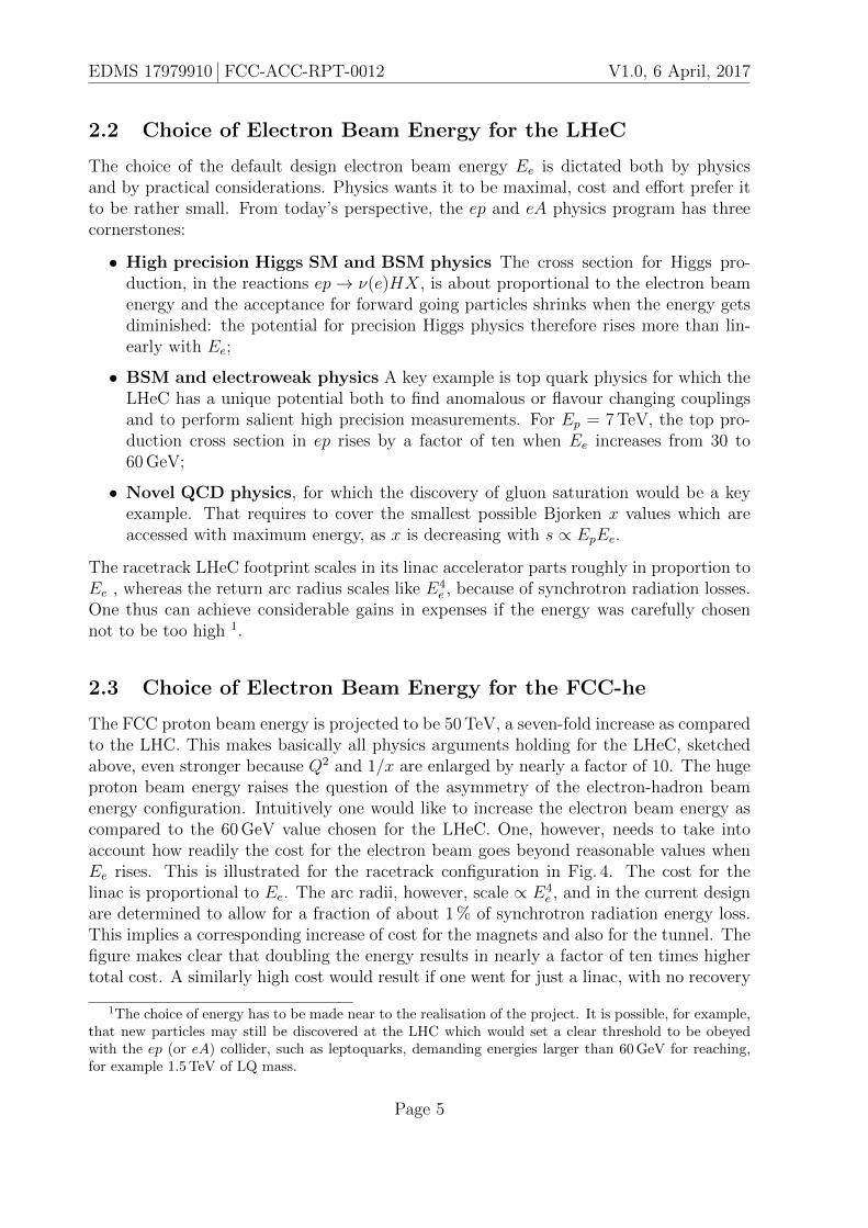
2.2 Choice of Electron Beam Energy for the LHeC
The choice of the default design electron beam energy Ee is dictated both by physicsand by practical considerations. Physics wants it to be maximal, cost and effort prefer itto be rather small. From today’s perspective, the ep and eA physics program has threecornerstones:
• High precision Higgs SM and BSM physics The cross section for Higgs pro-duction, in the reactions ep→ ν(e)HX, is about proportional to the electron beamenergy and the acceptance for forward going particles shrinks when the energy getsdiminished: the potential for precision Higgs physics therefore rises more than lin-early with Ee;
• BSM and electroweak physics A key example is top quark physics for which theLHeC has a unique potential both to find anomalous or flavour changing couplingsand to perform salient high precision measurements. For Ep = 7 TeV, the top pro-duction cross section in ep rises by a factor of ten when Ee increases from 30 to60 GeV;
• Novel QCD physics, for which the discovery of gluon saturation would be a keyexample. That requires to cover the smallest possible Bjorken x values which areaccessed with maximum energy, as x is decreasing with s ∝ EpEe.
The racetrack LHeC footprint scales in its linac accelerator parts roughly in proportion toEe , whereas the return arc radius scales like E4
e , because of synchrotron radiation losses.One thus can achieve considerable gains in expenses if the energy was carefully chosennot to be too high 1.
2.3 Choice of Electron Beam Energy for the FCC-he
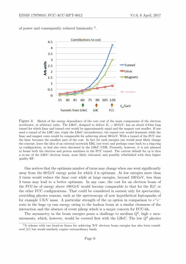
The FCC proton beam energy is projected to be 50 TeV, a seven-fold increase as comparedto the LHC. This makes basically all physics arguments holding for the LHeC, sketchedabove, even stronger because Q2 and 1/x are enlarged by nearly a factor of 10. The hugeproton beam energy raises the question of the asymmetry of the electron-hadron beamenergy configuration. Intuitively one would like to increase the electron beam energy ascompared to the 60 GeV value chosen for the LHeC. One, however, needs to take intoaccount how readily the cost for the electron beam goes beyond reasonable values whenEe rises. This is illustrated for the racetrack configuration in Fig. 4. The cost for thelinac is proportional to Ee. The arc radii, however, scale ∝ E4
e , and in the current designare determined to allow for a fraction of about 1 % of synchrotron radiation energy loss.This implies a corresponding increase of cost for the magnets and also for the tunnel. Thefigure makes clear that doubling the energy results in nearly a factor of ten times highertotal cost. A similarly high cost would result if one went for just a linac, with no recovery
1The choice of energy has to be made near to the realisation of the project. It is possible, for example,that new particles may still be discovered at the LHC which would set a clear threshold to be obeyedwith the ep (or eA) collider, such as leptoquarks, demanding energies larger than 60 GeV for reaching,for example 1.5 TeV of LQ mass.
Page 5
EDMS 17979910 FCC-ACC-RPT-0012 V1.0, 6 April, 2017
of power and consequently reduced luminosity 2.
Figure 4: Sketch of the energy dependence of the core cost of the main components of the electronaccelerator, in arbitrary units. The LHeC, designed to deliver Ee = 60 GeV, has an about 8.9 km longtunnel for which linac and tunnel cost would be approximately equal and the magnet cost smaller. If oneused a tunnel of the LHC size, triple the LHeC circumference, the tunnel cost would dominate while thelinac and magnet costs would be comparable for achieving about 90 GeV. With a tunnel of the FCC sizethe linac becomes the smallest part of the cost. In fact for such energies one would most likely changethe concept, leave the idea of an external racetrack ERL (see text) and perhaps come back to a ring-ringep configuration, as had also been discussed in the LHeC CDR. Presently, however, it is not plannedto house both the electron and proton machines in the FCC tunnel. The current default for ep is thena re-use of the LHeC electron beam, most likely relocated, and possibly refurbished with then higherquality RF.
One notices that the optimum number of turns may change when one went significantlyaway from the 60 GeV energy point for which 3 is optimum. At low energies more than3 turns would reduce the linac cost while at large energies, beyond 100 GeV, less than3 turns may lead to a better optimum. In any case, the cost for an electron beam ofthe FCC-he of energy above 100 GeV would become comparable to that for the ILC orthe other FCC configurations. That could be considered in earnest only for spectacular,overriding physics reasons, such as the spectroscopy of now hypothetical leptoquarks offor example 5 TeV mass. A particular strength of the ep option in comparison to e+e−
rests in the huge ep cms energy owing to the hadron beam at a similar cleanness of theinteraction and the absence of event pileup which is a major concern for FCC-hh.
The asymmetry in the beam energies poses a challenge to medium Q2, high x mea-surements, which, however, would be covered first with the LHeC. The low Q2 physics
2A scheme with two head-on linacs for achieving TeV electron beam energies has also been consid-ered [11] but would similarly require extraordinary funds.
Page 6

EDMS 17979910 FCC-ACC-RPT-0012 V1.0, 6 April, 2017
instead is better covered, if Ee was not chosen too high. This is illustrated in Fig. 5. It sois concluded that the ERL of the LHeC, providing a 60 GeV electron energy beam, mayserve as the appropriate baseline for the conceptual design of the FCC-eh configuration.If indeed the LHeC was built prior to the HE-LHC or the FCC, ep collisions could berealised at very low cost from the start of these highest energy pp colliders.
1
10
10 2
10 3
10 4
10 5
10 6
10 7
10 -8 10 -7 10 -6 10 -5 10 -4 10 -3 10 -2 10 -1 1
Figure 5: Kinematics of the FCC-he for Ep = 50 TeV and Ee = 60 GeV. Blue dashed: lines of constantscattered electron energy, which for Q2 below 1000 GeV2 never exceeds 65 GeV. Red dashed: lines ofconstant electron polar angle. One observes that the low x region is very well accessible with a detectoracceptance to backward electrons down to one degree. Black dashed-dotted: lines of constant hadronicfinal state energy. At large Borken x, energies of up to tens of TeV are scattered in the forward detectorregion; Black dotted: lines of constant polar angle of the hadronic final state. One can see that the highx, medium Q2 ∼ 103−4 GeV2 region is hardly accessible with the FCC-he, it yet would have been coveredby the LHeC before.
Page 7

EDMS 17979910 FCC-ACC-RPT-0012 V1.0, 6 April, 2017
3 Parameters
3.1 Luminosity Estimate for Future ep Colliders at CERN
The luminosity L of the LHeC as of the FCC-he, in a simplified model, is given by thefollowing formula
L =NpNefγp4πεpβp
·HgeomHb−bHcoll (1)
Here, Np is the number of protons per bunch and εp and βp are the proton emittanceand beta-functions. We assume that the proton beam parameters Np and εp are definedby the main experiments that collide protons off protons because the default assumptionis one of concurrent ep and pp operation. For the proton beta-function in the electron-proton collision point we assume a challenging target value of βp = 15 cm. This may beachievable because only one proton beam needs to be focused, which is a simplificationcompared to the proton-proton case. f = 1/∆ denotes the bunch frequency, which forthe default bunch spacing of ∆ = 25 ns is= 40 MHz.
Ne is the number of electrons per bunch which determines the electron current Ie =eNef . The electron current for HE-LHC and FCC-eh is assumed3 to be Ie = 20 mA, aslight increase compared to the 15 mA assumed for the LHeC in the HL LHC phase andtriple the value of 6.4 mA used in the LHeC CDR. This will yield a total synchrotronradiation of about 40 MW in the return arcs. To compensate for this power loss throughthe beam, a grid power of the order of 65 MW may be required. A value of 20 mA isnowadays already in reach or has even been surpassed with intense DC photocathodes.Since, however, a cavity has to stand the sixfold of Ie due to the (de)acceleration in threeturns one should be careful in choosing Ie not to be too large. The factors Hgeom, Hb−b
and Hcoll are geometric correction factors with values typically close to unity. Hgeom isthe reduction of the luminosity due to the hourglass effect, Hb−b is the increase of theluminosity by the strong attractive beam-beam forces and Hcoll is a factor that takesthe filling patters of the electron and the proton beam into account. Estimates for theseparameters are shown in Tab. 1. Unless discussed above, further parameters used for thefour ep collider configurations considered can be found i) for the LHeC as evaluated inits conceptional design in Ref. [5], ii) for the high luminosity version of the LHeC inRefs. [12, 13, 8], iii) for the energy doubler of the LHC, the HE-LHC in Refs. [14, 15]and for the FCC-he in Ref. [14, 15]. One observes that compared to the CDR of theLHeC from 2012, it seems possible to achieve peak luminosities near to or larger than1034 cm−2s−1, which makes these future ep colliders most exciting and efficient machinesfor the study of new physics at the accelerator energy frontier.
3The numbers quoted hold for unpolarised electron beams. One may currently expect a polarisedelectron source to provide half of that current which requires further developments as are ongoing for weakinteraction measurements such as at MESA. In order to achieve luminosities of order 1033 with positronssignificant developments are required. For positrons dedicated operation at very high luminosity may bea particularly attractive option as the loss in lepton intensity is compensated by a gain in proton andoperation performance as indicated below.
Page 8
EDMS 17979910 FCC-ACC-RPT-0012 V1.0, 6 April, 2017
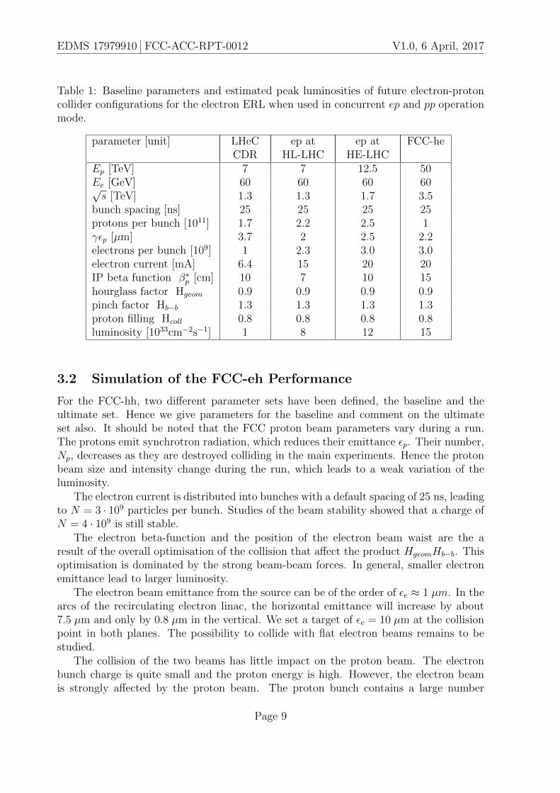
Table 1: Baseline parameters and estimated peak luminosities of future electron-protoncollider configurations for the electron ERL when used in concurrent ep and pp operationmode.
parameter [unit] LHeCCDR
ep atHL-LHC
ep atHE-LHC
FCC-he
Ep [TeV] 7 7 12.5 50Ee [GeV] 60 60 60 60√s [TeV] 1.3 1.3 1.7 3.5
bunch spacing [ns] 25 25 25 25protons per bunch [1011] 1.7 2.2 2.5 1γεp [µm] 3.7 2 2.5 2.2electrons per bunch [109] 1 2.3 3.0 3.0electron current [mA] 6.4 15 20 20IP beta function β∗
p [cm] 10 7 10 15hourglass factor Hgeom 0.9 0.9 0.9 0.9pinch factor Hb−b 1.3 1.3 1.3 1.3proton filling Hcoll 0.8 0.8 0.8 0.8luminosity [1033cm−2s−1] 1 8 12 15
3.2 Simulation of the FCC-eh Performance
For the FCC-hh, two different parameter sets have been defined, the baseline and theultimate set. Hence we give parameters for the baseline and comment on the ultimateset also. It should be noted that the FCC proton beam parameters vary during a run.The protons emit synchrotron radiation, which reduces their emittance εp. Their number,Np, decreases as they are destroyed colliding in the main experiments. Hence the protonbeam size and intensity change during the run, which leads to a weak variation of theluminosity.
The electron current is distributed into bunches with a default spacing of 25 ns, leadingto N = 3 · 109 particles per bunch. Studies of the beam stability showed that a charge ofN = 4 · 109 is still stable.
The electron beta-function and the position of the electron beam waist are the aresult of the overall optimisation of the collision that affect the product HgeomHb−b. Thisoptimisation is dominated by the strong beam-beam forces. In general, smaller electronemittance lead to larger luminosity.
The electron beam emittance from the source can be of the order of εe ≈ 1 µm. In thearcs of the recirculating electron linac, the horizontal emittance will increase by about7.5 µm and only by 0.8 µm in the vertical. We set a target of εe = 10 µm at the collisionpoint in both planes. The possibility to collide with flat electron beams remains to bestudied.
The collision of the two beams has little impact on the proton beam. The electronbunch charge is quite small and the proton energy is high. However, the electron beamis strongly affected by the proton beam. The proton bunch contains a large number
Page 9

EDMS 17979910 FCC-ACC-RPT-0012 V1.0, 6 April, 2017
of particles and the electron energy is not very high. During the collision the electronbunch is focused by the protons, which leads to an important reduction of the transverseelectron beam size. As a consequence the luminosity is larger than for rigid beams. Also,the conventional matching of the sizes of the two beams would not work because theelectron bunch size is changing by a factor of two or so during the collision. Hence,we simulated the beam-beam effect with GUINEA-PIG [16]. We varied the longitudinalposition of the waist and the beta-functions for optimum luminosity.
Finally, the factor Hcoll is given by the fraction of electron bunches that collide witha proton bunch. Only 80% of the FCC-hh circumference is filled with proton bunches,hence 20% of the electron bunches will not collide with a proton bunch. This leads toa collision factor Hcoll = 0.8. Depending on the filling pattern of the proton ring itcould be possible to use an electron beam bunch pattern that has no bunches in non-colliding positions. This would reduce the rate of electron bunches by 20 % and allowto increase their charge by 25 %. The luminosity would increase by 25 %. However, wedo not assume this option in the baseline. Accelerating the non-colliding bunches maybe useful for limiting the fluctuations of the RF power stored into the linacs. A smallfraction of non-colliding bunches is known to be of interest also for the understandingof backgrounds and the detector response. The bunch distribution of the electron beamcould be affected by another process. The electron beam ionises the rest gas in the linacsand arcs. The positive ions may then be trapped in the electron beam which can lead toan instability [5]. The instability can be suppressed by introducing a gap in the electronbeam. During the passage of this gap the ions will be lost [5].
The result of the simulation study is summarised in Tab. 2. They are in good agreementwith the rough estimate presented above (Tab. 1).
Table 2: Parameters and estimated peak and integrated luminosities of the FCC-he,when the 50 TeV proton and the 60 GeV ERL electron beams collide, in an operationmode where simultaneously pp data may be taken.
Parameter Unit Protons ElectronsBeam energy GeV 50000 60
Normalised emittance µm 2.2→ 1.1 10IP betafunction mm 150 42→ 52
Nominal RMS beam size µm 2.5→ 1.8 1.9→ 2.1Waist shift mm 0 65→ 70
Bunch population 1010 10→ 5 0.31Bunch spacing ns 25 25
Luminosity 1033cm−2s−1 18.3→ 14.3Int. luminosity per 10 years [ab−1] 1.2
Page 10
EDMS 17979910 FCC-ACC-RPT-0012 V1.0, 6 April, 2017
3.3 Dedicated ep Operation
There could be an interest in dedicated ep operation because one readily observes possiblesignificant gains in the instantaneous and integrated luminosity performance: A firstestimate hints to a possibly 10 fold higher proton beam brightness and a reduced betafunction, by perhaps a factor of two, with only one beam present and squeezed and lessaperture constraints. A factor of two may also be obtained from the much enhancedoperation efficiency in dedicated mode, mainly because the proton beam lifetime wouldbe hugely increased without pp collisions, which lead to τp < 5 h. Therefore, dedicated epruns could be typically a day long, and overall, in dedicated mode, luminosities in excess ofO(1035) cm−2s−1 appear to be not unrealistic. An integrated luminosity of 1 ab−1 annuallywould be possibly to achieve. Such a scenario could be specially relevant for taking a largeamount of positron-proton data in not a too long period of operation, since the e+ currentswill be much lower, by one or even two orders of magnitude, than the e− currents.
4 Electron-Ion Collisions
The heavy ion beams that the CERN injector complex can provide to the LHC, the HE-LHC and the FCC provide a unique basis for high energy, high luminosity deep inelasticelectron-ion scattering physics. Since HERA was restricted to protons only, the LHeC(FCC-eh) extends the kinematic range in Q2 and 1/x by 4 (5) orders of magnitude. Thisis a huge increase in coverage and would be set to radically change the understanding ofparton dynamics in nuclei and of the formation of the quark gluon plasma. In principle,the LHC could also be operated at injection energy and the electron beam at low energy.Therefore the LHeC, as an EIC, could also cover the kinematic range of the low energyelectron-ion colliders currently under consideration in the US and in China, although withlower luminosity.
An initial set of parameters in the maximum energy configurations was given in [15].This did not yet take account of the intense beams of 208Pb82+ nuclei that have alreadybeen largely demonstrated [17] and are foreseen to be provided to HL-LHC. Combiningthese with the default 60 GeV electron ERL, an updated parameter set is presented herein Table 3.
Radiation damping of Pb beams in the hadron rings is about twice as fast as forprotons and can be fully exploited. For the case of the FCC-hh, the emittance values inTable 3 are estimates of effective average values during a fill in which Pb-Pb collisions arebeing provided at one other interaction point [18].
Page 11

EDMS 17979910 FCC-ACC-RPT-0012 V1.0, 6 April, 2017
Table 3: Baseline parameters of future electron-ion collider configurations based on theelectron ERL, in concurrent eA and AA operation mode.
parameter [unit] LHeC (HL-LHC) eA at HE-LHC FCC-heEPb [PeV] 0.574 1.03 4.1Ee [GeV] 60 60 60√seN electron-nucleon [TeV] 0.8 1.1 2.2
bunch spacing [ns] 50 50 100no. of bunches 1200 1200 2072ions per bunch [108] 1.8 1.8 1.8γεA [µm] 1.5 1.0 0.9electrons per bunch [109] 4.67 6.2 12.5electron current [mA] 15 20 20IP beta function β∗
A [cm] 7 10 15hourglass factor Hgeom 0.9 0.9 0.9pinch factor Hb−b 1.3 1.3 1.3bunch filling Hcoll 0.8 0.8 0.8luminosity [1032cm−2s−1] 7 18 54
5 Summary
Table 1 summarises the current choices of the parameters for the available energy frontierep collider configurations at CERN. All are based on the racetrack, multi-turn ERL asthe default choice for the electron accelerator, and in each case it is assumed that epand pp were operated at the same time. The ERL technology is worldwide under intensedevelopment and a design concept is about to be published [9] for demonstrating themain choices of the specific ERL configuration which is the base for the here sketched epcolliders.
The LHeC was originally designed to achieve about 1033 cm−2s−1 luminosity. With thediscovery of the Higgs boson an update to increased luminosity had been initiated whichis under way. Using the HL-LHC and increasing Ie at somewhat diminished βp moved theluminosity to close to1034 and an integrated luminosity of O(1) ab−1 appears as realistic,ultimate goal for a decade of LHeC operation.
If the HE-LHC was built, it would boost the ep cms energy of the LHeC to nearly2 TeV, beyond the acceptance limit for leptoquarks at the LHC. The luminosity would beas large as 1034. For the FCC-he the parameters as discussed above would enable a peakluminosity of O(1034) too. An interesting option is the possibility to achieve luminositiesof O(1035) in dedicated ep operation with enhanced efficiency for the proton beam lifetimewould not be reduced by pp collisions.
If the FCC was operated in the ultimate mode, Np would be reduced by a factor of5 but the emittance by more than fivefold also, such that the proton beam brightnessstayed about the same. If for the ultimate FCC-pp the bunch spacing was kept at 25 nsone thus would also reach L = O(1034). Lower values came out, however [14], if ∆ = 5 ns
Page 12
EDMS 17979910 FCC-ACC-RPT-0012 V1.0, 6 April, 2017
was chosen, as is an option for limiting the high pile-up in pp interactions.The LHeC and its successor, the FCC-he, would represent the most powerful, high res-
olution microscopes of matter the world could construct. These had a unique DIS, Higgsand BSM physics programme. Moreover, they made the LHC and later the FCC-hh com-plete and enabled precise measurement leading much beyond our present understandingof nature. The luminosity potential is a factor of 1000 larger than that of HERA, whichmake the CERN based energy frontier ep and eA colliders an exciting subject for furtherstudy.
Acknowledgement
We thank our many collaborators for insight and their work on the physics, detector andaccelerator design, the FCC coordination group for its attention to the electron-hadronconfiguration, the CERN directorate for its interest and support and the InternationalAdvisory Committee of the LHeC/FCC-he development for encouragement and guidance.
Page 13

EDMS 17979910 FCC-ACC-RPT-0012 V1.0, 6 April, 2017
References
[1] Elliott D. Bloom et al. High-Energy Inelastic e p Scattering at 6-Degrees and 10-Degrees. Phys.Rev. Lett., 23:930–934, 1969.
[2] Martin Breidenbach et al. Observed Behavior of Highly Inelastic electron-Proton Scattering. Phys.Rev. Lett., 23:935–939, 1969.
[3] M. Klein and R. Yoshida. Collider Physics at HERA. Prog.Part.Nucl.Phys., 61:343–393, 2008.
[4] H. Abramowicz et al. Combination of measurements of inclusive deep inelastic e±p scattering crosssections and QCD analysis of HERA data. Eur. Phys. J., C75(12):580, 2015.
[5] J. Abelleira Fernandez and the LHeC Study Group. A Large Hadron Electron Collider at CERN.Journal of Physics G: Nuclear and Particle Physics, 39(7):075001, 2012.
[6] U. Klein. Higgs Physics at the LHeC. Contribution to ICHEP, Valencia, 2014.
[7] M. Klein. Deep inelastic scattering at the energy frontier. Annalen Phys., 528:138–144, 2016.
[8] G. Apollinari et al. HL-LHC: Preliminary Design Report. Yellow Report CERN-2015-005, 2015.
[9] G. Arduini et al. Powerful Energy Recovery Linac Experiments. Conceptual Design Report, toappear, 2017.
[10] C. Cook and J. Osborne. Civil Engineering for the FCC-he. Talk presented at the FCC Workshopat Rome, 2016.
[11] V. Litvinenko. A Lepton Energy Recovery Linac Scalable to TeV Energies. Contribution to the FCCWorkshop at Washington DC, 2015.
[12] Frank Zimmermann, Oliver Brning, and Max Klein. The LHeC as a Higgs Boson Factory. InProceedings, 4th International Particle Accelerator Conference (IPAC 2013): Shanghai, China, May12-17, 2013, page MOPWO054, 2013.
[13] O. Bruening and M. Klein. The Large Hadron Electron Collider. Mod.Phys.Lett., A28(16):1330011,2013.
[14] D. Schulte et al. FCC-he Parameters. Talk presented at the FCC Workshop, Rome, 2016.
[15] F. Zimmermann. FCC Accelerator Parameters. Talk presented at the FCC Physics Week, Geneva,CERN, 2017.
[16] D. Schulte. Study of Electromagnetic and Hadronic Background in the Interaction Region of theTESLA Collider. DESY-TESLA-97-08, 1997.
[17] J. Jowett and H. Bartosik. LHC Performance Workshop, Chamonix, January 2017https://indico.cern.ch/event/580313/. 2017.
[18] A. Dainese et al. Heavy ions at the Future Circular Collider, arXiv:1605.01389. 2016.
Page 14