future roles for autonomous vertical lift in disaster ... · future roles for autonomous vertical...
TRANSCRIPT

T233-1-1
Future Roles for Autonomous Vertical Lift in Disaster Relief and Emergency Response
Larry A. Young [email protected]
Flight Vehicle Research and Technology Division Ames Research Center
Moffett Field, CA 94035
Summary System analysis concepts are applied to the assessment of potential collaborative contributions of autonomous system and vertical lift (a.k.a. rotorcraft, VTOL, powered-lift, etc.) technologies to the important, and perhaps underemphasized, application domain of disaster relief and emergency response. In particular, an analytic framework is outlined whereby system design functional requirements for an application domain can be derived from defined societal good goals and objectives.
Nomenclature
!
A• Solution space concept/need “attributes” matrix
!
B• Solution capability matrix
!
C• Concept “confidence” matrix
D Vector/array representing the consistency of the particular individual technology with strategic technical direction guidance
!
gi s( ) “Gap” defining relative magnitude of actual/realizable need with respect to theoretical need (for ith need)
!
F• Solution space frequency matrix
!
" K( ) Requirements-to-design-parameters operator G1 Candidate technology goals matrix G2 Candidate technology objectives matrix GW Vehicle gross weight K Vector/array representing the cost associated
with the development/implementation of a particular individual technology (1 low to 10 high)
!
M• Solution space magnitude matrix
!
N• “Need” array
!
N• Complementary (dual-use) need array
n Vehicle load factor
!
pi s( ) Probability distribution function of required ith “need,” subject to s, the severity, or magnitude, of a disaster/emergency
!
P K( ) Supposition rules operator
Presented at Heli Japan 2006, Aichi, Japan, November 15-17, 2006.
Q QFD-inspired autonomous-system-technology-to-goals matrix
q QFD-inspired emerging (non-autonomous) technology-to-goals matrix
s “Severity,” or magnitude, of overall need R Vehicle range
!
R Functional requirements matrix
!
R• Solution space “return” matrix
!
" “Residual” between “need” and “solution space” metrics
!
S• Possible solution matrix
T Vector/array captures institutional core competency expertise or growth interest in a particular individual technology, ranging from 0 to 10 (no to high expertise/interest)
!
T• Task matrix
U Vector/array representing the risk of development/implementation of a particular individual technology (1 low to 10 high)
V Vehicle velocity
!
"* Normalized intelligence metric
!
"* Normalized autonomous system implementation elegance metric
!
" “Total system” predictive capability “level of fidelity,” ranges from 0 to 10 (low to high)
ηG “Growth” factor array (ηG >1) ηM “Margin” factor array (ηM >1)
!
" Level of Autonomy (LOA), 0≤
!
"≤5, “aleph”
https://ntrs.nasa.gov/search.jsp?R=20070017927 2020-04-16T14:39:19+00:00Z

T233-1-2
Introduction
There is considerable anecdotal evidence for the value of rotorcraft assets for humanitarian and disaster relief missions – e.g. Refs. 1-2. Figure 1 illustrates just one of the many capabilities rotorcraft have with respect to disaster relief missions – in this case the conduct of a SAR mission. Development of new vehicles, systems, and technologies can potentially lead to significant advances in life saving activities. In parallel with this design innovation, new system analysis techniques must be used to assess the relative merits of these disaster relief and emergency response (DRER) system concepts. Conjectured key enablers anticipated for new vehicle, and complementary (or auxiliary) system, concepts for future DRER capabilities is autonomous system and robotic technologies.
Fig. 1. Helicopters in Disaster Relief (Image Courtesy of the US Coast Guard)
The objective of this paper is threefold. The first
objective is to focus on the development of system analysis techniques to support analysis of disaster relief and emergency response missions and vehicle/system concepts. In particular, the paper will concentrate on defining and illustrating a formal process of going from established societal good goals (i.e. disaster relief and emergency response, for this paper) to defining a broad spectrum of notional functional requirements. The end result of this effort is a diverse set of disaster relief and emergency response concepts, primarily focused on the potential of autonomous vertical lift, and an outlined formal process by which a recommended portfolio of key technologies can be identified that support those concepts. The second objective of the paper is to recognize and respect the growing importance of emergency response and disaster relief missions to society as a whole by surveying and investigating this nascent technology research topic. Finally, the third
objective is to propose and advance the proposition that autonomous vertical lift platforms and robotic rescue capabilities are powerful agents for improving disaster relief and emergency response.
This paper is the latest installment in a series of
papers examining the system analysis techniques appropriate to address the earliest (the essential foundation) stages of the engineering design process, with particular emphasis on identifying and managing emerging technologies. References 3-4 examined the implications of incorporating autonomous system technologies into system analyses (a theme continued, in part, in this paper). Reference 5, in turn, examined the implications of the conceptualization and conceptual design process on the identification and management of portfolios of critical enabling technologies for given missions/application domains; this work (as well as the related work of Refs. 6-11) touch upon the emergence of autonomous system technologies and robotic systems to address wholly new aerospace missions and capabilities. This paper will focus on laying the analytic groundwork to robustly/rigorously translate societal good goals to design functional requirements (refer to Fig. 2).
The proposed system analysis, ideally, should aid
in the discovery/identification of the unexpected, or at least non-obvious, potential solution subset for the disaster relief and emergency response aerial vehicle and auxiliary system design challenge. Too many times the outcome of system analysis exercise is merely self-validation of the “obvious,” i.e. the initial/going-in system conceptual design and concept of operations (CONOPS). This is neither an optimal or desirable outcome of system analysis.
Fig. 2. System Analysis, Conceptual Design, and the Research and Technology Process

T233-1-3
In addition to vehicle design there is a larger
scope of possible area of study for DRER that includes: mission operations/procedures, equipment (complementary and/or support and auxiliary systems), and systemic advancements (infrastructure, policy, etc.) -- refer to Fig. 3. Ideally advancements should be directed to all three major phases: the pre-disaster planning/staging phase, the response phase, and the recovery phase. How or does technology (and specifically autonomous vertical lift aerial vehicles) play in all this? Further, is there a need for technological innovation and research and development to address the “application domain” of disaster relief and emergency response? These are questions that only rigorous system analysis can address.
Fig. 3. Sub-Domains with respect to the Disaster Relief Application Domain
The Status Quo It is nearly an impossible task to adequately
describe the ongoing humanitarian need for resources – including aerial assets. Nonetheless, a modest attempt to describe those needs must be hazarded in order to begin to appreciate the challenge. Relying on information provided in United Nation (UN) publications, e.g. Refs. 12-14, Fig. 4 illustrates the scope of the disaster relief problem. As is clear from Fig. 4, there appears to be an escalating need to support DRER missions.
Some of the many contributions of rotorcraft to
recent disaster relief responses are detailed in Refs. 1-2. A lessons-learned perspective can be found in Ref. 15, which highlighted, in particular, the need for improved communication and coordination among
aerial assets to support natural disaster relief efforts. One only has to look to recent media reports of the unparalleled efforts by the USCG and the US National Guard to begin to appreciate the outstanding contributions of these organizations in responding to national disaster relief efforts. The current complement of U.S. Coast Guard (USCG) aerial assets can be found on the USCG website: http://www.uscg.mil/USCG.shtm. Cited on that website was a total of 211 aircraft in the USCG inventory. Fixed-wing aircraft (C-130 turbo-props and HU-25 jet aircraft) operate from large and small air stations. Rotary wing aircraft (HH-65 and HH-60 helicopters) operate from flight-deck equipped cutters and air stations/facilities. Some of the many US DOD efforts in support of disaster relief and humanitarian aid missions (from an air lift/mobility perspective) are documented in Ref. 16 (particularly the data found in Appendices A & B of that document). Additionally, among the status quo background research performed for this paper, Ref. 17 (among other references) helped provide estimates of yearly flight hours and dedicated EMS helicopter assets in the United States. Reference 17, for example, estimated that between 1972 and 2002 EMS assets in the U.S flew approximately 3 million flight hours and 2.75 million patients. Correspondingly, Refs. 18-19 provided a unique perspective on Japanese disaster response efforts and considerations. In particular, Ref. 18 discusses an essential component of effective disaster relief efforts, especially in the earlier stages of the response – (the lack of) information exchange. Reference 19 discusses trauma transport statistics in Japan as well as the Japanese doctor-helicopter program. The well-known EMS “golden hour” rule of thumb is cited in this paper in support for the use of helicopter aeromedical transport. Reference 12 provides information regarding recent UN/international perspectives on disaster preparation and relief efforts. Reference 14 provides historical trends, or statistics, as to worldwide disaster relief and humanitarian aid efforts – including mortality trends (refer to Fig. 4). A general policy framework for integrating helicopters and tiltrotor aircraft into disaster relief operations is detailed in Ref. 20. Finally, the results of a NASA workshop on public service helicopters, circa 1980, are summarized in Refs. 42-43.

T233-1-4
0 500 1000 1500 2000 2500 3000
1900-1909
1910-1919
1920-1929
1930-1939
1940-1949
1950-1959
1960-1969
1970-1979
1980-1989
1990-1999
2000-2004
Decad
e
Number of Natural Disasters (a)
1 10 100 1000 10000 100000
Earthquake, Pakistan
Hurricane, Guatemala
Hurricane, United States
Earthquake, India
Flood, India
Earthquake, Indonesia
Flood, China
Earthquake, Iran
Measles Epidemic, Nigeria
Flood, Pakistan
Number of Deaths (b)
Fig. 4. UN Disaster Statistics: (a) World-Wide Historical Trends and (b) 2005 Statistics (note logarithmic scale)
However, it should be noted, that because of cost
and safety concerns even the relatively common-place EMS helicopter aeromedical support mission is under increasingly skeptical and/or judicious examination, e.g. Ref. 21 among many such studies. It is under this environment that strong cost-effective and demonstrable arguments for advanced technology in support of the disaster relief and emergency response application domain must be made.
Research & Advanced Technology Why concern ourselves with the pros and cons of
advanced technologies to meet future disaster relief challenges when clearly there are so many compelling requirements for even the most basic of resources and equipment here and now? The following considerations are offered for studying disaster relief and emergency response operations as a research and technology application domain: 1. arguably this is an under-served application domain with respect to technology investment (given the relative importance, and visibility with respect, to the general public); 2. Support of disaster relief efforts are often seen as a
level of resource issue and not as a technology issue and, yet, technology investments would ideally be directed to maximize response/relief efficiency and thus reduce overall resource requirements over time; 3. Disaster relief efforts have mostly relied on, or leveraged (perhaps, arguably, overly so), non-dedicated-public-service (commercial and military) aerial assets; 4. It is the contention of this paper that new emerging technologies are poised to make significant advancements; 5. This application domain makes a compelling system analysis topic given the limited attention focused to date on this topic area as well as the unique constraints, metrics, and goals/objectives underlying this domain.
Can technology be leveraged to define improved
strategies for providing adaptive, efficient and effective, responses to both the small emergencies and large catastrophes? How can this question best be analytically addressed or studied? To proceed in addressing these questions, an identification of the “societal good” goals must first be performed. What are these societal good goal then (the need for improvement over the status quo) underlying disaster relief and emergency response missions? It is proposed that this societal good goal can be expressed as: to save all those who can be saved, to provide relief to all those who suffer, irrespective of the size of the disaster or the remoteness or inaccessibility of those who need help. Commensurate with this goal are the following application objectives: 1. Improved safety for rescue/recovery efforts both for response teams and victims; 2. Faster, and more comprehensive, response to even the most inaccessible locations, severe operational or environmental conditions, and daunting infrastructure limitations; 3. Flexible scalability of response to meet even the greatest of relief/emergency challenges; 4. Efficiency in usage/distribution of limited/high-value resources; 5. Maximize survivability of victims; 6. Minimize property/infrastructure damage (through pre- and post-incident actions); 7. Expedite recovery through optimum damage/security surveys and (re-)distribution of resources and overall aid; 8. Do all of the above while maximizing affordability of the assets/equipment employed and resources expended during the overall response; 8. Provide wholly new and/or unprecedented capabilities and services to the response/recovery effort.
It is difficult to conduct system analyses for
application domains where widely-recognized performance metrics are hard to come by. There appears to be no universally recognized scale or measure for disaster relief planning. Nonetheless there have been some attempts to devise such metrics and perform the associated analyses, e.g. Ref. 22, but more work in this area is required. Further, it is

T233-1-5
extremely difficult to conduct planning exercises for wholly random events. Mankind tends to think of disasters to be random strokes of misfortune – and on an individual, person by person by basis, this may be true. However, collectively or rather world-wide, disasters are not that random. At any given moment in time there is a continuous great need for the tools and personnel to respond to a wide-spectrum of human suffering. As such, planning is not only possible but essential.
From a systemic perspective, governments have
often turned to their respectively military forces and assets to lead the way in the response to major disasters. But how can the design constraints tied to military effectiveness be balanced or influenced to insure disaster and emergency response effectiveness? Clearly there is a long litany of common capability requirements, but are there unique opportunities/capabilities that are being inadequately addressed or going unanswered altogether? Civil, public service, and police assets are, of course, also an important component of any large emergency response. Optimizing these civil, police, and other public-service contributions, while at the same time maximizing coordination and interoperability, are important technological considerations. Therefore, for example, one of the technology areas later identified for possible technology investment is network-centric systems for disaster relief missions.
The vehicle concepts discussed later in this paper
will build off of previous work – i.e. Refs. 5-7. These concepts are briefly summarized in Appendix A. Vehicle/system integration opportunities and challenges are based in part on ideas presented in Refs. 8-11. The system analysis examining the influence of rotorcraft technology on disaster relief efforts and emergency response builds upon recent work (Refs. 3 and 5) in the related areas of intelligent systems and technical-goals and objectives definition and enabling and enhancing technology portfolio management. The work presented in this paper specifically addresses “societal good goal” identification and valuation as impacted by concepts and technology advancements (for the broad category of technologies affecting life saving activities, as particularly influenced by autonomous vertical lift capability).
The vehicle concepts, and associated system
analysis work, will focus on a number of notional mission categories, including: deployment of high-value rescue/medical equipment; search and rescue (SAR) from extremely hazardous (and currently impossible to access) environments; cost-effective pre-positioning of assets for disaster relief
contingencies; EMS or medevac; natural/man-made hazard monitoring.
A couple of cautionary notes should be
highlighted as this point. It is important to acknowledge the potential for appearing insensitive to victims and the general populace while attempting to field test immature equipment and concepts during actual disaster responses. Field tests, while vital from a technological perspective, must not be seen as engaging in marginal exercises that seem more stunt than legitimate attempts to render aid or support. Finally, it should be noted that care must be taken to not remove or overly minimize the human “face” in disaster relief efforts, particularly if robotic and/or autonomous systems do indeed become a major part of such efforts. People in pain and suffering will always need to ultimately be able to turn to a fellow human for comfort and/or compliant when tested subjected to extreme hardship. Robotic/autonomous systems can complement, but not replace, the human first-responders to disasters.
System Analysis of the Influence of Rotorcraft Technology on Disaster Relief Efforts
An important question to consider is: how is this
application domain (disaster relief) unique and/or similar to other domains as regards conceptual design and, correspondingly, system analysis? Among the unique attributes of the disaster relief application domain are: 1. the necessity of significant emphasis of leveraged multi-mission/end-user usage of assets; 2. the difficulty or ambiguity in defining mission return on investment and other metrics required for quantitative system analysis; 3. the extensive, wide-ranging, and extremely difficult to optimize -- either analytically or in practice -- “solution space” of systems, resources, operational and policy considerations critical for the successful conduct of even the modest of disaster relief missions/campaigns; 4. the difficulty in accounting for the uncontrolled human element in the engineering design; 5. finally, the inherent difficulty in studying and proposing/developing improved solutions for the patently chaotic, uncertain, and near-unforeseeable conditions and constraints underlying disaster relief missions.
Another important question to consider is how to
evaluate system/operations concepts in lieu of mature preliminary/detail designs, proof-of-concept prototypes, and/or rigorous simulation modeling? In this regard, the concept of “supposition rules” is introduced in this paper. These supposition rules and their underlying rationale will be discussed in detail in Appendix B.

T233-1-6
Functional Requirements The following discussion regarding the
interaction of the design conceptualization process and the robust definition of system design functional requirements is a work in progress. Nonetheless, the concepts and methodology outlined below should provide value to those interested in design and system analysis, as well as those researchers in the vertical lift and autonomous system communities. Additionally, though preliminary in nature, this methodology does shed some light on critical considerations with respect to the applicability of advanced technology investments towards the disaster relief and emergency response application domain.
This question of establishing functional
requirements on the basis of societal good goals and objectives has been treated in a number of ways by other researchers – including focus groups, advisory panels, market and/or customer surveys, gap analysis, and many other techniques. In this paper, an alternate quantitative/analytic approach is suggested and evaluated with respect to the problem of defining functional requirements for complex engineering applications. This latest system analysis work complements the work presented in Refs. 3-5.
The overall proposed methodology for
quantitatively defining system design functional requirements is schematically illustrated in Fig. 5. As shown, the proposed process is iterative in nature with nonlinear intermediate (with both human innovation/conceptualization input as well as deterministic analytic estimation) processes.
What follows next is the definition of a
Need/Solution-Space (NSS) formulation for deriving functional requirements. Instead of being founded in terms of economic modeling (such as cost-effectiveness analysis (CEA), Ref. 23, and cost-benefit analysis (CBA), Refs. 23-24). The NSS methodology is conceptually (design-wise) and technologically oriented. Instead of proceeding from the supply and demand paradigm one proceeds from a problem and solution perspective (and, thereby, demanding a optimal balance between estimated needs and potential solution spaces with associated design concepts and new technologies).
Fig. 5. Defining Functional Requirements & Establishing Scope of Potential Solution Space
As will be seen, the NSS methodology has
aspects reminiscent of operations research, systems engineering task decomposition, and even AI (artificial intelligence) rule-based reasoning. But, first, it is appropriate to ask why develop this new analytical methodology at all, though? Why not attempt to apply CBA or CEA analyses to this problem? In particular, because the focus of this work is on the earliest stages of functional requirements definition and the design conceptualization process, CBA is not applicable in that it is impossible to define, with anywhere near the accuracy required, estimates of the cost of design concepts (product) being considered. For CBA to be applicable the solution spaces being considered would have to be fairly mature both technology- and design-wise. This limitation, though, is directly counter to the intent of this work, which is to focus on promising innovative concepts and emerging technologies.
The first step to deriving functional requirements
is to define the societal goals/objectives in terms of quantitative “need” metrics. There are two components to individual contributions to a societal good goal “need”: a probabilistic component, in the form of some probability density function (pdf), and

T233-1-7
the “gap” component that attempts to account for the difference in magnitude between the theoretical maximum need and the actual realizable need.
!
Ni• " gi s( )pi s( )ds
0
#
$
(1) And, further, it is assumed that
!
gi s( ) = ai sbi
(2) Where ai and bi are the
!
gi s( ) power-law constants, s is the severity/magnitude of the need, and
!
pi s( ) is one member of a set of probability density functions (pdf’s) describing various societal good needs. For the disaster relief application, data from various United Nations (UN) organizations, governmental bodies, and non-governmental organizations (NGO) can be considered source material for the empirical definition of such pdf’s. Given the empirical nature of
!
pi s( ) , numerical integration of Eq. 1 is required for defining the individual element values of the needs array. In principle, an empirical, historically based, pdf can be defined for each and every societal good objective defined to support the overall good goal.
By way of illustration, consider for the moment a
key disaster relief objective (as summarized earlier), which is to maximize the survivability of victims. Let then
!
pi s( ) be the empirical probability density function (one per “need” as noted above) corresponding to historical mortality trends for various disasters based on some measure of severity, s, of such disasters. Further, recognizing that it is highly unlikely that every victim survive to point of rescue and recover through medical intervention, then it is necessary to define the gap function,
!
gi s( ) , so as to reflect the anticipated actual survivability as a consequence of improved rescue/relief intervention; by definition
!
0 < gi s( ) < 1. The greater the “gap” the greater the anticipated need. The greater the “gap,” in this case, the greater the potential survivability of victims through improved intervention, and, therefore, the greater the “need” for innovative solutions to improve that intervention. Figure 6 illustrates a conjectural pdf distribution for the loss of life due to disaster.
0
500
1000
1500
2000
2500
0 2 4 6 8 10 12
Disaster Severity, s
Mo
rta
lity
per
un
it T
ime
Du
e to
Na
tura
l D
isa
ster
s
Fig. 6. Conjectured Form of PDF (by way of illustration) for Loss-of-Life-Due-to-Disaster (per unit time period)
Defining the power-law coefficients underlying
the proposed functional form of the gap function is a non-trivial task. There are four approaches one can take in defining this function: arbitrary assignment of constant values, a Delphi-like polling of subject matter experts (SME’s), e.g. Ref. 25, correlation/trending relative to the current-practice rescue and survivorship rates, and, finally, definition on the basis of post-mortem forensic data establishing statistically the mean time of death relative to the primary incident (disaster or emergency) occurrence. The later approach would obviously the most accurate means of establishing potential disaster survivorship, however, because of resource limitations (to perform the required autopsies and forensic analysis) and possible cultural influences (prohibiting or inhibiting the conduct of autopsies) such a post-mortem assessment/analysis might be extremely difficult to perform.
In general the needs array can be characterized as
follows
!
N•
=
Potential Return for Societal
Goal Objective # 1
MPotential Return for Societal
Goal Objective # nO
"
#
$ $ $ $ $
%
&
' ' ' ' '
(3) Specifically for the case of the disaster relief and
emergency response application domain, the needs array has the form of

T233-1-8
!
N•
=
Lives, or recovery $, saved by realization of
societal good goal objective # 1M
Lives, or recovery $, saved by realization of
societal good goal objective # nO
"
#
$ $ $ $ $
%
&
' ' ' ' '
(4)
Correspondingly, there is in general a requirement to define a complementary, or dual-use, application needs matrix. I.e.,
!
N•
=
Potential Complementary, or
Dual -Use, Return for Societal
Goal Objective # 1
MPotential Complementary, or
Dual -Use, Return for Societal
Goal Objective # nO
"
#
$ $ $ $ $ $ $ $
%
&
' ' ' ' ' ' ' '
(5) The collective sum total of possible solutions,
broadly/comprehensively applied to all of the application domain “needs” and potential complementary, or dual-use, “needs,” should ideally balance each other out, if a nearly optimal system design is conceived. This can be analytically represented as
!
" # $G1i$M1i
Ni•
+$W$G2i$M 2i
N i• % Sij
•
j
&'
(
) ) )
*
+
, , ,
i
&
- 0
(6)
Equation 6 presupposes for every set of societal goals and objectives there can be defined a matching set of “needs,”
!
N•. Further, for every ith “need,” there
is a corresponding set of j possible solutions (in the form of system or operational concepts). Given all of this, the above relationship essentially asserts that there exist optimal combinations of solutions to address the established needs. Therefore, if
!
" < 0 then the identified possible solution space is likely too broad/expansive and, therefore, too costly to explore/implement; if
!
" > 0 then the suite of needs is being unmet and the current solution space is too sparse; only if
!
" = 0 is the solution space appropriately sized for the anticipated suite of needs to achieve the societal good goals/objectives.
Inevitably, the Eq. 6 relationship is iterative in nature; only through successive cycles of conceptualization and need assessment can an acceptable solution space be arrived at and reasonable functional requirements be established. Note, finally, that for additional analysis flexibility that growth and margin factors,
!
"Gi
and
!
"M i
, are built into Eq. 6. Additionally, the scalar parameter
!
"W
provides the relative weight between the primary application needs and complementary needs.
The possible solution matrix has the general form
!
S•
=
Incremental return
for concept #1,
as applied
to obj. # 1
L
Incremental return
for concept #nC ,
as applied
to obj. # 1
M M MIncremental return
for concept #1,
as applied
to obj. # nO
L
Incremental return
for concept #nC ,
as applied
to obj. # nO
"
#
$ $ $ $ $ $ $ $ $ $ $
%
&
' ' ' ' ' ' ' ' ' ' '
(7)
Specifically, for the disaster relief application domain the possible solution matrix has the form
!
S•
=
Incremental (to obj.
# 1) $ return for
rescue & recovery
for concept # 1
L
Incremental (to obj.
# 1) $ return for
rescue & recovery
for concept # nC
M M MIncremental (to obj.
# nO ) $ return for
rescue & recovery
for concept # 1
L
Incremental (to obj.
# nO ) $ return for
rescue & recovery
for concept # nC
"
#
$ $ $ $ $ $ $ $ $ $ $
%
&
' ' ' ' ' ' ' ' ' ' '
(8)
The above possible solution matrix has to have element values expressed in terms of either lives, or recovery funds saved, so as to be consistent with the needs array. Further, for additional consistency, these element values resolve down to a single unit for “return” value, i.e. dollars. Placing a dollar value on a human live may be distasteful (note Ref. 22 regarding alternate analysis approaches without having to monetize human life and well-being) from a number of different perspectives, but from a system analysis perspective it is quite necessary.

T233-1-9
A series of task matrices,
!
T• , can be defined as
in Eq. 9.
!
T•
=
" Value" of Task
# 1 for Function,
or Mission, # 1
L
" Value" of Task
# 1 for Function,
or Mission, # nMM M M
" Value" of Task
# nT for Function,
or Mission, # 1
L
" Value" of Task
# nT for Function,
or Mission, # nM
"
#
$ $ $ $ $ $ $ $
%
&
' ' ' ' ' ' ' '
(9)
For the disaster relief application, the following missions and tasks have been identified in Table 1. The representative missions and tasks summarized in Table 1 provide the framework for defining the previously noted
!
T• matrix.
The solution space matrix can be derived by the
expression
!
Sij•
= Fij•Mij
•Rij
• (10)
Where
!
F• is the frequency of usage (sorties) of the jth
concept to meet ith objectives and
!
M• is the
magnitude of use (e.g. number of dedicated disaster relief aircraft). Note that the unit of time used in
!
F•
has to be consistent with that used in
!
N• and
!
N•.
!
Rij•
=Cij
•
nT nMTkl
•Bkl
•
l=1
nM
"k=1
nT
"For jth concept
#
$ % %
& % %
'
( % %
) % %
(11)
Where, in Eq. 11,
!
B• is the solution capability
matrix (with element values 0 if a given concept cannot perform a given functional/mission task and 1 if it potentially can). The constants
Tn and
Mn are
the number of tasks and the number of missions respectively.
!
C• is the concept confidence matrix
(which defines an assessment of how well a given concept can perform the sum aggregate of all mission tasks, or, in other words, how well the concept successfully meets the societal good objectives). The confidence matrix is directly influenced by the supposition rules defined for the particular application domain to be studied, more to follow on that topic later.
Table 1 – Representative Disaster Relief
Mission/Tasks Mission #1 (SAR, Search and Rescue) – Ground taxiing; runway or vertical TOL; cruise to search area; maintain communications with multiple assets; perform in-flight situational awareness and collision avoidance monitoring; over-flight of prescribed search pattern; communicate location of target if acquired; return to base upon location of target or need for refueling. Mission #2 (Damage/Recovery Surveys) –
(All of the above, plus tasks noted below) #2A (Aerial Survey Only) – Perform over-flight of not only prescribed waypoints & target search areas but to engage in active/adaptive search using an assortment of flight behaviors (e.g. Refs. 26-27); perform in-flight damage assessments using heuristic analysis techniques, as well as relay raw data and assessments back to home base. . #2B (Surface Interaction) – VTOL at remote sites, under unknown and uncertain conditions; air-deploy, as need be, sensors and devices over targets of interest; ground-deploy, as need be, sensors & devices; perform sampling and other manipulation of the immediate environment of the vehicle while on the ground; exert ground/surface mobility (in a hybrid sense) as need be; automated servicing and maintenance pre- & post-missions.
Mission #3 (Utility Transport of Equip/Supplies) – #3A (Basic Relief Supplies) – Ground taxiing; runway or vertical TOL; cruise to remote relief camp; maintain communications with base and relief camp; perform in-flight situational awareness and collision avoidance monitoring; remote site (rough & short-strip) runway or vertical TOL, under largely uncontrolled and uncertain conditions; deploy supplies to authorized camp personnel; highly automated (internal) cargo handing equipment; interaction with potentially inadequately trained relief workers or local authorities. #3B (Heavy/Specialized Equipment; Internal Stored) – (All of the above, plus tasks noted as follows); automated deployment of equipment, including (relayed from base) teleoperation of self-propelled equipment driven off vehicle. #3B (Heavy/Specialized Equipment; External Slung Load) – VTOL required; cargo handling automation & devices capable of safely attaching and/or releasing slung loads at remote sites by potentially untrained (or even non-present) ground personnel. #3D (Automated/Robotic Rescue Equipment) – VTOL required; deployment (air & ground and with & without ground personnel assistance) robotic rescue devices (and, as need be, control systems); loiter and support (networking/communication and control of rescue devices from the air.
Mission #4 (Medical Transport) – VTOL required for aerial transport; advanced human-system-interaction, including telepresence, to provide safe and effective implementation or maintenance of care in-flight; specialized automated, and perhaps robotic, medical systems for advanced in-flight care. Mission #5 (Refugee Transport) – Runway or Vertical TOL; (novice) human-system-interaction, including telepresence, to provide safe and supportive embarkation, disembarkation, and in-flight comfort and care. Mission #6 (Security/Stabilization) – Deployment (air & ground) of sensors, devices, and robotic (and non-robotic) security assets to insure safe and effective relief distribution -- even in the face of unpredictable, or even openly hostile, elements.

T233-1-10
Therefore, given the above and the Table 1 task
summary, the
!
T• matrix has the specific form for the
disaster relief application domain as shown in Eq. 12. Note that in constructing the task matrix,
!
T• , from the
Table 1 tasks, that each task in the above table has four variants: i.e. the given task can be performed manually, can be executed through remote-control or teleoperation, semi-autonomously (where a task sequence is initiated by a human operator but the task execution is automated), or autonomously (initiation and execution of the task is performed without any human intervention). It is possible, in defining the solution capability matrix,
!
B• that corresponds to a
given
!
T• matrix, that a design concept may (or may
not) be able to perform any number of these task variants – e.g. an optionally-piloted vehicle will sometimes perform tasks manually and sometimes autonomously. Both the
!
B• and
!
T• matrices have
the dimension
!
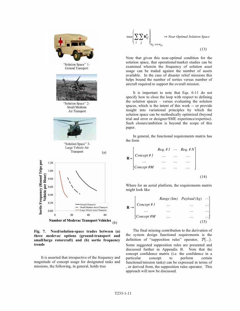
nT " nM . A simple illustrative example is shown in Fig. 7
that hopefully provides some insight into the type of need/solution-space tradeoffs implied by Eqs. 6 and 10. In this example the need is expressed as requiring a total medevac transport rate of 100 passengers per hour (PAX/hour). A number of assumptions are made with respect to the Fig. 7 sortie frequency versus total vehicles deployed trends: 1. the mean number of ground transport medevac is PAX = 4; 2. the mean number of small/medium aerial transport medevac is PAX = 8; 3. the mean number of large vehicle Aerial transport medevac is PAX = 20. Further, each transport mode is treated a separate, independent solution space (i.e. for simplicity, for illustrative purposes, no combinations of transport modes are examined). Additionally, all three solutions are assumed to perform all required tasks for the medevac mission with roughly the same confidence (as embodied in Eq. 11). Finally, a maximum sortie rate, 1.0 round trip per vehicle per hour, and a minimum rate, 0.333 round trips per vehicle per hour, was employed for the Fig. 7 results.
!
T•
=
"Value" of Manual Taxiing to Runway for SAR Mission
L L
"Value" of Teleoperated Taxiing to Runway for SAR Mission
L L
"Value" of Semi-Autonomous Taxiing to Runway for SAR Mission
L L
"Value" of Autonomous Taxiing to Runway for SAR Mission
L L
"Value" of Manual Runway Takeoff for SAR Mission
L L
L L L
L L L
"Value" of Autonomous Runway Takeoff for SAR Mission
L L
"Value" of Manual Vertical Takeoff for SAR Mission
L L
L L L
L L L
"Value" of Autonomous Vertical Takeoff for SAR Mission
L L
"Value" of Manual Hover for SAR Mission
L L
L L L
L L L
"Value" of Autonomous Hover for SAR Mission
L L
M M M
M M M
M M M
M M M
"Value" of Manual Vertical Landing for SAR Mission
L L
L L L
L L L
"Value" of Autonomous Vertical Landing for SAR Mission
L L
M M M
M M M
M M M
M M M
"
#
$ $ $ $ $ $ $ $ $ $ $ $ $ $ $ $ $ $ $ $ $ $ $ $ $ $ $ $ $ $ $ $ $ $ $ $ $ $ $ $ $ $ $ $
%
&
' ' ' ' ' ' ' ' ' ' ' ' ' ' ' ' ' ' ' ' ' ' ' ' ' ' ' ' ' ' ' ' ' ' ' ' ' ' ' ' ' ' ' '
(12)
T233-1-11
(a)
(b)
Fig. 7. Need/solution-space trades between (a)three medevac options (ground-transport andsmall/large rotorcraft) and (b) sortie frequencytrends
It is asserted that irrespective of the frequency andmagnitude of concept usage for designated tasks andmissions, the following, in general, holds true
!
max Rij•
j
"i
"#
$
%%%
&
'
(((
nC >>nO
) Near Optimal Solution Space
(13)
Note that given this near-optimal condition for thesolution space, that operational/market studies can beexamined wherein the frequency of solution assetusage can be traded against the number of assetsavailable. In the case of disaster relief missions thishelps bound the number of sorties versus number ofaircraft required to support the overall mission.
It is important to note that Eqs. 6-11 do notspecify how to close the loop with respect to definingthe solution spaces – versus evaluating the solutionspaces, which is the intent of this work -- or provideinsight into variational principles by which thesolution space can be methodically optimized (beyondtrial and error or designer/SME experience/expertise).Such closure/ambition is beyond the scope of thispaper.
In general, the functional requirements matrix hasthe form
!
R =
Req. # 1 L Req. # N
Concept # 1 K K K
K K K K
Concept #M K K K
"
#
$$$$
%
&
''''
(14)
Where for an aerial platform, the requirements matrixmight look like
!
R"
Range (km) Payload (kg) L
Concept # 1 K K K
K K K K
Concept #M K K K
#
$
%%%%
&
'
((((
(15)
The final missing contribution to the derivation ofthe system design functional requirements is thedefinition of “supposition rules” operator,
!
P K( ) .Some suggested supposition rules are presented anddiscussed further in Appendix B. Note that theconcept confidence matrix (i.e. the confidence in aparticular concept to perform certainfunctional/mission tasks) can be expressed in terms of, or derived from, the supposition rules operator. Thisapproach will now be discussed.

T233-1-12
A need/solution attributes matrix must now be defined such that
!
A•
=
Concept/Need Attribute # 1
M
Concept/Need Attribute # nA
"
#
$ $ $
%
&
' ' '
(16) Or, specifically for the case of the disaster relief application and given the supposition rules in Appendix B, the •
A matrix has a typical form of
!
A•
=
V , representative velocity
R, representative range
Operational complexity
s, disaster or need severity
Self - deployment capability
"t, mission representative duration
System design complexity
n, aerial vehicle(s) load factor
GW, aerial vehicle(s) gross weight
L
L
L
#
$
% % % % % % % % % % % % % % % %
&
'
( ( ( ( ( ( ( ( ( ( ( ( ( ( ( (
(17)
There is one attributes matrix, •A , per ith societal
good objective and jth concept. The concept confidence matrix, •
C can notionally be expressed in a semi-quantitative manner by means of the nonlinear, interactive, and the semi-indeterminate
!
P K( ) operator; i.e.
!
Cij•
= P A•"
# $ %
& '
For ith objective& jth concept
(18) The concept confidence matrix, •
C , establishes the confidence in each concept – for the current iteration of the solution space – to successfully contribute to each, and every, societal good objective. Note that the unknown
!
P K( ) operator has to be implicitly solved for from a set of “supposition rules.” The supposition rules are intended to embody qualitative “common sense” design considerations for the particular engineering application being studied. Appendix B summarizes some of these rules for the disaster relief application domain.
Finally, the system design functional
requirements, in principle, can be derived from the following relationship
!
R =
max A1•
For AllObjectives
"
#
$ $ $
%
&
' ' ' Concept #1
L max AnA
•For AllObjectives
"
#
$ $ $
%
&
' ' ' Concept #1
M M M
max A1•
For AllObjectives
"
#
$ $ $
%
&
' ' ' Concept #nC
L max AnA
•For AllObjectives
"
#
$ $ $
%
&
' ' ' Concept #nC
(
)
* * * * * * * * *
+
,
- - - - - - - - -
(19)
Equation 19 holds true when the near-optimal
(maximum value) condition, Eq. 13, is approached. The above relationship balances the risk versus potential payoff of the solution space, given the need/solution attributes and the supposition rules employed.
Concepts & Technology Goals A quantitative methodology by which technology
goals and objectives (versus societal good goals, objectives, and needs) can be identified -- and general technology portfolios defined and managed -- has

T233-1-13
been previously outlined in Ref. 5. This methodologywill now be summarized and applied to the disasterrelief and emergency response application domain.
The total system design parameters matrix, P, isthe result of some generalized operator,
!
" K( ) , asapplied to the system design requirements, R.Conceptually, this nonlinear (and perhaps iterative)operator embodies the sum total of analyses anddesign-tools as applied to the design problem, at agiven assumed level of fidelity.
!
P =" R( ) (20)
The general form of the design parameters matrixis as follows
!
P =
Param. # 1 L Param. # O
Concept # 1 K K K
K K K K
Concept # M K K K
"
#
$$$$
%
&
''''
(21)
Where, again, the operator,
!
" K( ) , maps thefunctional requirements to the design parameters, withsome given level of fidelity (dependent in part onwhat phase of the design/analysis process is beingundertaken) for each parameter estimate.
Reference 5 defined a general (and iterative)concepts-to-technology-goals process. This process issummarized in Fig. 9.
Fig. 9. Mapping Functional Requirements, andDesign Parameters (for a suite of systemconceptual designs), to Technical Goals andObjectives
The resulting analytic framework leading toquantitative candidate metrics for the technology goals
and objectives matrix,
!
G , provides an important toolfor engineering managers. Refer to Ref. 5 for moredetails and an application of this methodology toaerobot (small autonomous aerial vehicle)concepts/missions.
Conceptualization and Technology Portfolios
Cost should be of paramount concern as to anytechnology investments and implementation into thedisaster relief and emergency response applicationdomain. This emphasis is reflected in the “technicaldirections” matrix (refer to Fig. 10) used in theconceptualization and technology portfolioidentification process. (Note that theconceptualization “technical directions” are intendedas a means by which institutional design philosophycan be accounted for in the conceptualization process.)In large part this is the case because there isanticipated that there might be from a policyperspective, a forced trade-off between investments indisaster preparedness and response and humanitarianrelief (or poverty alleviation) requirements. It wouldbe extremely unfortunate to see reduction in generalongoing humanitarian relief efforts (stemming fromchronic poverty) as a consequence of improvedpreparations for future geophysical (or other source)catastrophe.
Fig. 10. Design for Improved Disaster Relief:Conceptualization “Technical Directions”
Table 2 summarizes the functional dependence ofsystem level of autonomy, ! , and the normalizedintelligence metric, *! , on mission type – assumingsuch missions are performed with no human operatoronboard the aircraft. The definitions of levels ofautonomy (LOA or
!
") and the normalized intelligencemetric,
!
"* , are based on the work of Ref. 3. In short,the following definitions are used: LOA=0 designatesremote control such as in a simple RC model airplane;
T233-1-14
LOA=1 implies simple onboard automation such as a rudimentary autopilot; LOA=2 for remotely operated (teleoperated) aerial platforms and other systems; LOA=3 for highly automated or semi-autonomous; LOA=4 for fully autonomous; LOA=5 collaborative operations between several autonomous/robotic systems, including other autonomous aerial vehicles. Autonomy is defined for the purposes of this paper as the ability to independently perform without human intervention actions, tasks, or roles. Intelligence measures how well these actions, tasks or roles are performed under varying degrees of task and environmental complexity and other associated constraints and conditions. And, elegance is the computational efficiency by which the autonomous vehicle intelligence is implemented. The normalized scales for intelligence and elegance, by convention, range in value from 0 to 10.
Table 2 – Interdependence of Level of Autonomy &
Normalized Intelligence on Mission Type Mission ! *! Mission #1 – Search and Rescue 5 10 Mission #2 - Damage & Recovery Surveys
#2A - Aerial Survey Only #2B - Surface Interaction
3 5
3 6
Mission #3 - Utility Transport of Equip. & Supplies
#3A - Basic Relief Supplies #3B – Heavy or Specialized
Equipment; Internal Stored #3B – Heavy or Specialized
Equipment; External Slung Load
#3D – Automated or Robotic Rescue Equipment
4
4
5
5
5
5
7
8 Mission #4 - Medical Transport 5 10 Mission #5 - Refugee Transport 4 8 Mission #6 – Security & Stabilization
5 6
A quantitative methodology by which
autonomous system technology portfolios can be identified and managed has been previously outlined in Refs. 3-4. This methodology will now be summarized and applied to the disaster relief and emergency response application domain.
The primary means of defining and managing
autonomous system technology portfolios is to identify how a potential portfolio influences, effects, overall technology goals and objectives (including, most importantly, those technology goals and objectives not directly related to autonomous
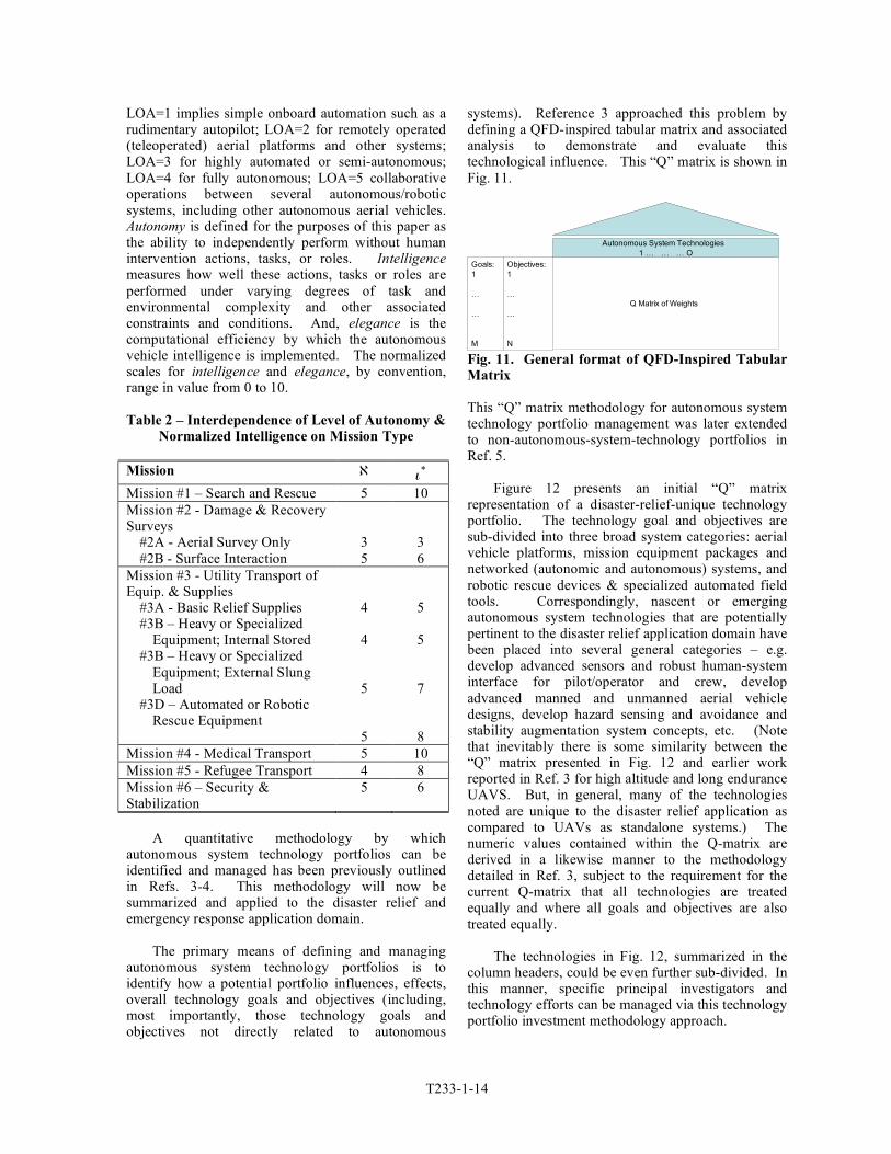
systems). Reference 3 approached this problem by defining a QFD-inspired tabular matrix and associated analysis to demonstrate and evaluate this technological influence. This “Q” matrix is shown in Fig. 11.
Autonomous System Technologies
1 … … … O
Q Matrix of Weights
Objectives:
1
…
…
N
Goals:
1
…
…
M
Autonomous System Technologies
1 … … … O
Q Matrix of Weights
Objectives:
1
…
…
N
Goals:
1
…
…
M Fig. 11. General format of QFD-Inspired Tabular Matrix
This “Q” matrix methodology for autonomous system technology portfolio management was later extended to non-autonomous-system-technology portfolios in Ref. 5.
Figure 12 presents an initial “Q” matrix
representation of a disaster-relief-unique technology portfolio. The technology goal and objectives are sub-divided into three broad system categories: aerial vehicle platforms, mission equipment packages and networked (autonomic and autonomous) systems, and robotic rescue devices & specialized automated field tools. Correspondingly, nascent or emerging autonomous system technologies that are potentially pertinent to the disaster relief application domain have been placed into several general categories – e.g. develop advanced sensors and robust human-system interface for pilot/operator and crew, develop advanced manned and unmanned aerial vehicle designs, develop hazard sensing and avoidance and stability augmentation system concepts, etc. (Note that inevitably there is some similarity between the “Q” matrix presented in Fig. 12 and earlier work reported in Ref. 3 for high altitude and long endurance UAVS. But, in general, many of the technologies noted are unique to the disaster relief application as compared to UAVs as standalone systems.) The numeric values contained within the Q-matrix are derived in a likewise manner to the methodology detailed in Ref. 3, subject to the requirement for the current Q-matrix that all technologies are treated equally and where all goals and objectives are also treated equally.
The technologies in Fig. 12, summarized in the
column headers, could be even further sub-divided. In this manner, specific principal investigators and technology efforts can be managed via this technology portfolio investment methodology approach.

T233-1-15
Fig. 12. QFD-Inspired Matrix Identifying Influence of Autonomous System Technologies on Disaster Relief System Technology Goals and Objectives

T233-1-16
Figure 13 illustrates the breadth and depth of technologies applied to the disaster relief application (where “breadth” being directly proportional to the number of technology goals and objectives and “depth” as to the number of technologies contributing to a particular technology goal or objective).
Figure 14 presents the relative “weight” of a
given technology area to the overall potential contribution to the identified technology goals and objectives. In this particular case, consistent with the Q-matrix shown in Fig. 12, uniform weighting
is assigned to all individual technologies and uniform priority is assigned to all technology goals and objectives. The higher the weight of a given technology area, the greater its anticipated contribution to the overall technology goals and objectives. Given this initial Q-matrix distribution, Fig. 14 confirms that the autonomous mobile robotics technology area might be an especially promising area of research for the disaster relief mission application. Note that Figs. 3 and 4 are derived purely from Fig. 12.
0 10 20 30 40 50 60 70 80
Improved Aero-Performance for Utility & Transport
Operational/Environmental Flexibility & Resilience ("Storm of the
Century"-Proof Flight)
Improved/Novel Mobility
Improved/Enhanced Cabin Environment ("Surgery-Room"-Smooth
Ride)
Enhanced Safety with Increased Operability
Improve Command, Control ("Influence"), Communication with
Large, Disparate Relief Communities
Pre-Incident "Sleeper" or Cached Asset Staging & Persistence
Coordinating large numbers of semi- & fully-autonomous robots &
systems
Improved Search & Situational Assessment (to hear the quietest
call for help)
Rescue from Previously Intractable Hazards
Improved delivery of Medical Aid
Expedite Recovery
Enhance Stabilization & Security
Number of Applicable Technologies
Fig. 13. Breadth and Depth of Technologies Considered
0 1 2 3 4 5 6 7 8
Develop Advanced Sensors & Robust Human-System Interface for
Pilot/Operator & Crew
Develop Advanced Manned and Unmanned Aerial Vehicle Designs
Develop Hazard Sensing & Avoidance & Stability Augmentation
System Concepts
Develop Vehicle Management System (Planning/Decision-Making
& Task Execution) with Situational Awareness & Adaptability
Develop Automated Emergency/Disaster Management Concepts &
Tools
Tailored Network-Centric Technologies for Disaster-Relief
Develop Autonomic/Autonomous Ground-Based and/or Fieldable
Support Systems (e.g. autonomous base camps for UAVs/UGVs)
Hybrid, Multi-Modal, and/or Modular Mobility Systems
Advanced (Mobile) Robotics
Relative Weight of Technologies
Fig. 14. Relative Weighting of Technology Areas

T233-1-17
Using the normalized intelligence metric forautonomous systems, see Ref. 3, as an indicator foroverall development progress for an autonomoussystem technology portfolio, Fig. 15 illustrates thetrend of technologies invested in as a function ofincreased normalized intelligence. Note that ahighly nonlinear trend, or sudden jumps in thetechnology development trend, with increasingnormalized intelligence would suggest a possibleunrealistic investment strategy and/or inefficientintroduction of new technologies into anapplication domain.
Fig. 15. Number of technologies to beadopted/invested in as a function of requirednormalized intelligence level
An illustration of the potential to tracktechnology portfolio progress is shown in Fig. 16.From Ref. 3, for a given level of normalizedintelligence, there a two measures by which systemperformance can be evaluated: an objective“mission success” metric derived from missionsimulations incorporating the individualautonomous system technologies in specified set ofvehicle/mission scenarios, and a technologist’ssubjective “self-assessment” of the normalizedtechnology readiness level (TRL) of the jth
autonomous system technology.
Figure 16 illustrates that as the normalizedintelligence metric investment target is increased,and with increased mission-success and TRL level,the technology portfolios (matching the intelligenceinvestment target) naturally with contribute more tothe identified technology goals and objectives.Therefore, the greater the investment so to will bethe likely contribution to the goals. Further, thegreater the objective and subjective measures ofsuccess then, of course, as well, the contributions tothe goals.
0
0.1
0.2
0.3
0.4
0.5
0.6
Aer
ial
Veh
icle
Pla
tfo
rms
Mis
sio
n E
qu
ipm
ent
Pac
kag
es &
Net
work
ed
(Au
ton
om
ic/A
uto
no
mo
us)
Syst
ems
Roboti
c R
escu
e D
evic
es &
Spec
iali
zed A
uto
mat
ed
Fie
ldT
oo
ls
Fra
ctio
nal C
on
trib
uti
on
to T
ech
nolo
gy G
oals
Normalized Intelligence=7,Success=0.5
Norm.Intell.=5,Success=0.5
Norm.Intell.=3,Success=0.5
Norm.Intell.=7,Success=0.75
Norm.Intell.=5,Success=0.75
Norm.Intell.=3,Success=0.75
Fig. 16. Influence of normalized intelligence, mission simulation success (and TRL estimates) onTechnology Portfolio Management

T233-1-18
Table 3 summarizes the resultant technology portfolio as a function of missions (from Table 2) and the normalized intelligence metric investment target (from same analysis used to define Figs. 12-16). These initial technology investments would, of course, would shift about as a function of different weighting distributions in the Fig. 12 Q-matrix, reflecting differences in being identified as an enabling or enhancing technology (where in the current results all technologies are treated equally) or whether one group of technology goals and objectives are prioritized differently than the other goals/objectives (where, again, in the current results all goals and objectives are treated equally). And, of course, this methodology has the capability of tracking the progress being made towards goals and objectives and, thereby, allows a means of the modifying or otherwise adjusting the technology portfolios with time.
Table 3 – Autonomous System Technology Portfolio(s)
Normalized Intelligence,
!
"* = 1# 4 : Missions:
Damage & Recovery Surveys (Aerial Survey Only) Technologies:
"Evolvable Hardware" and integrated "autonomy & design" tools; dispatch and mission planning tools; multiple asset sensor fusion & integration with pre-& post-incident databases; standards for universal "mission computer" and communication systems system for public service rotorcraft; surface mobile robots; aerial robots with high-level self-directed goals and tasks/behavior; surface interactive systems; ground-based surveillance and security systems.
Normalized Intelligence,
!
"* = 5# 7: Missions:
Damage & Recovery Surveys (Surface Interaction); Security & Stabilization; Utility Transport of Equipment & Supplies (Basic Relief Supplies, Internal Stored Equip., and External Slung-Load Equip.)
Technologies: All of the above; enhanced crew-station interface/control systems for rescue and/or medical support and relief deployment; optionally-piloted vehicle flight-computer/control systems tailored to commercial & public service missions; active control of numerous, highly distributed micro-adaptive flow control devices & structural/wing-shape actuators; intelligent cameras; GNC in unknown and uncertain environments; vehicle-to-vehicle/robot-to-robot communication, negotiation/task-coordination to maximize agent task success; updated disaster simulation capability to include UAV, UGV, and robotic rescue device assets; aerial imaging analysis tool to estimate probable casualty/survivability metrics; local/decentralized "disaster-hardened" air traffic management systems; automated ground-based refueling/recharging of UAVs, UGVs, or mobile robotic systems; automated UAV/UGV servicing & maintenance; new software, robotic concepts, & (aerial or ground)
platform/vehicle concepts & hardware design tools; autonomous mid-air refueling of UAVs; automated (onboard and ground-based) diagnostic tools to assess vehicle health and support automated servicing/maintenance; automated launch/recovery systems; automated "hanger-handling" of UAVs/UGVs; automated maintenance of optimal internal environment; control systems for variable-geometry rotors and other (fixed) airframe components; novel actuators/effectors for efficient major configuration/geometry changes inherent in hybrid, multi-modal, and/or modular systems; highly automated tools & sensors; advanced telemedicine devices.
Normalized Intelligence,
!
"* = 8#10: Missions:
Utility Transport of Equipment & Supplies (Automated or Robotic Rescue Equipment); Refugee Transport; Medical Transport; Search and Rescue.
Technologies: All of the above; natural language interfaces; exotic human-system interface techniques such as electro-encephalogram (EEG) & head/eye-tracking operator control interfaces; synthetic vision "situational awareness" imaging monitors; hazard- & collision-avoidance sensors & monitoring systems compatible with extreme operating environments; "Human-factor-friendly" haptic and kinesthetic interfaces; flexible & powerful graphics user interfaces & symbology; control of innovative "intelligent" propulsion/propulsor systems; control/usage of multifunctional structures including distributed power sources; Lightweight/low-power miniature robust integrated avionics & sensors compatible with small UAVs/aerobots; new (adaptive) control laws/systems for operation of embedded actuators for rotor blades for primary flight control & 1+/rev active rotor control; vision-based image "classification' schemes by which near-field collision avoidance (other aircraft and/or bird-strike) is effected; vehicle-to-vehicle & vehicle-to-ATM collision-avoidance transponder beacon development; advanced stability augmentation systems to provide for acceptable low-altitude handling in high turbulent flow; load alleviation flight control laws and systems for operation in highly turbulent flowfields; easy-to-use, highly-capable "night-vision" systems & inclement weather or smoke/dust/fog-penetrating low-altitude sensors; automated take-off and landing in cluttered/congested obstacle-filled sites; automated/autonomous helicopter handling of slung-loads; standards for universal UAV/UGV ground-based operator control consoles that account for, or accommodate, public service missions; "urban canyon" flowfield realtime flow-visualization/navigation-aid tools for manned aircraft; "networked" black-box and emergency-beacon functions/systems for public service vehicles; deployment of autonomous emergency kiosks; plug & play and/or reconfigurable architectures for hybrid, multi-modal, and/or modular systems; integrated design tools for "rotorcraft as robots;” multi-modal control law development.
It should be cautioned that the above system
analysis results are only illustrative in nature. Considerably more work remains to arrive at a comprehensive and validated methodology linking the conceptualization and functional requirements definition processes.

T233-1-19
Concluding Remarks
This paper has attempted to pose andsubsequently address in a very preliminary way thefundamental question of whether advancedtechnology, particularly that pertaining to VTOLplatforms, has the potential to cost-effectivelyenhance the ability to save lives and speed recoveryefforts subsequent to disasters of various kinds.Clearly rotary- and fixed-wing assets alreadyprovide vital services for disaster relief andemergency response missions. However, it is thecontention/anticipation of this work -- supported byin-development design and system analyses -- thatnew technologies do indeed translate to newcapabilities, even for the disaster relief mission.
In particular, the use of autonomous aerialvehicles to deploy sundry robotic rescue devicespresents many intriguing possibilities as topotentially disaster relief mission needs. Suchcombined systems will likely achieve their greatestpotentiality by not being researched and developedin a piecemeal (system-by-system, incrementalcapability-by-capability) fashion but insteadthrough a comprehensive integrated effort.
The system analysis techniques developed andpresented in this paper -- as to systematically androbustly developing functional requirements forconceptual design and mission conceptdevelopment efforts -- will find great utility notonly for the disaster relief and emergency responseapplication but for many engineering applicationdomains as well.
During the course of writing this technicalpaper, the nation of Indonesia was struck by asevere earthquake near Yogyakarta on the island ofJava. As technologists we must always becognizant that the finest exercise of the engineeringprofession is the use of our abilities to solve thesometimes near-intractable problems required tomake society better. The rotorcraft communityclearly has the responsibility -- and privilege -- ofapplying our talents to the problem of improvingthe relief response to future disasters.
Appendix A – Some Conceptualization Results
A short summary of some of the conceptsconsidered in the system analysis performed ispresented in this appendix. In many regards, these
concepts are speculative in nature and are intendedto provoke a discussion within the vertical lift androbotic/autonomous system research communitiesas to what is within the realm of the feasible asregards innovative system design concepts.
“Sentinel” Networks
Emergency and disaster response could besignificantly enhanced by the establishing networksof automated (“autonomic”) emergency responsebase stations which support and coordinatesustained mission sorties of autonomous aerialvehicles for disaster relief support or emergencyresponse. This would potentially allow for theefficient pre-positioning of resources. Figure 18 isa notional illustration of one such automated basecamp and autonomous aerial vehicles beingdeployed from it; additionally, Fig. 18 shows howsuch base camps could be rapidly deployed (by air)upon need.
(a)
(b)
Fig. 18. “Sentinel” and Automated Base Camp(a) air-dropped/pre-positioned and (b)operational
In this regard the sentinel network conceptprimarily derives benefit from the autonomoussystem technology area of “autonomic/autonomousground-based and/or fieldable support systems”and, secondarily, from the technology area of“advanced manned and unmanned aerial vehicledesigns.” In particular, critical technologies need tobe developed as to enable: automated ground-based

T233-1-20
refueling/recharging of UAVs, uninhabited ground vehicles (UGVs), or mobile robotic systems; automated UAV/UGV servicing & maintenance; automated launch/recovery systems with automated "hanger-handling" of UAVs/UGVs.
Novel Concepts for Robotic Rescue
Novel concepts for rescue from high-rise
buildings, as influenced by rotorcraft, can be proposed and examined. Specifically, a few concepts to consider: 1. Hoist with rescue basket or chair that has additional degrees of freedom, and access, enabled through teleoperated or semi-autonomous ducted-fan propulsors to precision-guide-in basket/chair to victims in cluttered, congested, or otherwise hazardous environments (Fig. 19); 2. Hoist-lowered mobile SAR robotic devices (e.g., conceptually a jazzed-up version of commercial-off-the-shelf robotic “stair-climbing” wheel-chairs); 3. aquatic robots that could augment/replace rescue-swimmers for emergencies at sea (Fig. 20).
Fig. 19. “Vectored” Rescue Hoist Module Suspended from Helicopter
(a)
(b) Fig. 20. Helicopter Hoist-Deployed Robotic Rescue Device: (a) upright station-keeping and (b) and in motion
The “vectored” rescue-hoist and the robotic
rescue-swimmer concepts primarily derive benefit from the autonomous system technology area of “advanced (mobile) robotics.” In particular, critical technologies need to be developed as to enable: surface interactive systems and highly automated tools. Note that similar robotic rescue device concepts are being currently being studied, Refs. 30-34.
Mobile Telemedicine Triage System
Autonomous aerial vehicle vehicles deploy
high-value supplies/emergency-response hardware to the greatest need, irrespective of difficulty of access by conventional means. In particular, delivery of emergency robotic telemedicine systems by such autonomous aerial assets would be of great benefit. The potential for NASA-derived technology to support terrestrial- as well as space-based telemedicine systems has been previously identified in a series of studies, e.g. Refs. 28-29. Figure 21 illustrates a small notional aerial vehicle for delivery of such telemedicine systems – refer to Refs. 5 and 7 for additional discussion.

T233-1-21
Fig. 21. Coupling small autonomous aerial vehicles with high-value, critical-need telemedicine systems
Mobile telemedicine system concepts primarily
derive benefit from the autonomous system technology area of “advanced (mobile) robotics.”
Large-Scale, Rapid Decontamination and/or Minimized Dispersal of Hazardous Materials
Large scale (and rapid) environmental
decontamination and/or minimized dispersal of hazardous materials could be performed using autonomous aerial platforms. Rotary-wing platform capabilities should be examined as a basis for contamination mitigation and decontamination efficacy options. Such capabilities have been demonstrated by manned rotorcraft (Ref. 35), but unfortunately with a significant cost to the crew who flew the vehicles. Various rotary-wing mobility, autonomous system technologies, and various surfactant release/distribution options would need to be studied to arrive at an optimal design solution.
Optionally Piloted Rotorcraft for Exceptionally Hazardous Duty
Development of a fleet of optionally piloted
rotorcraft for exceptionally hazardous duty; providing for optionally piloted helicopters through teleoperation and other semi-autonomous system technologies. In particular, examine feasibility of private/government agreements sponsoring a dual-use volunteer conversion program to transform civil/public service helicopters to (upon need) optionally piloted platforms.
Teleoperation and autonomous system
technologies are key to the development of such optionally-piloted vehicles. Such vehicles are
already in development within the US military. Further, such an effort might also entail policy decisions related to implementation of government sponsorship of a volunteer conversion program to transform civil/public service helicopters to (upon need) optionally piloted platforms.
First Responder Rapid & Versatile Mobility
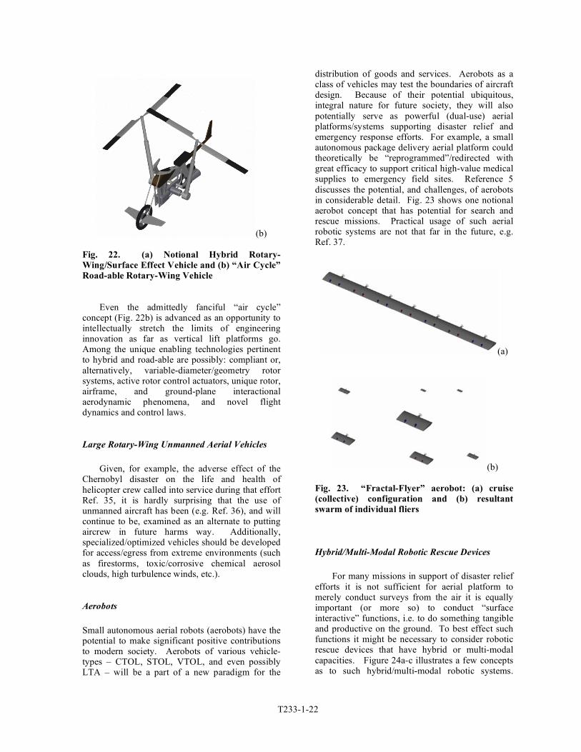
First responder mobility and response efficiency could potentially be significantly enhanced by resuscitating and modernizing the “Flying Jeep” concept – e.g. perhaps a hybrid ground-effect/rotary-wing platform. (Note that the concept of hybrid air-cushion and rotary-wing platforms was briefly touched upon in Ref. 7, in the context of micro-rotorcraft concepts.) A couple of notional concepts are shown in Fig. 22.
Whether merely elusive or illusionary, the
quest to develop a viable road-able, or hybrid, aerial vehicle has so far been unsuccessfully sought after by many. The lack of success, to date, however, does not negate the power and attractiveness of the concept. From an engineering research perspective, hybrid and/or road-able vertical lift aerial vehicles represent many intriguing areas of investigation. In terms of their potential contributions to supporting disaster relief and emergency response efforts they have many notionally attractive design features suitable/consistent with that application domain.
(a)
T233-1-22
(b)
Fig. 22. (a) Notional Hybrid Rotary-Wing/Surface Effect Vehicle and (b) “Air Cycle” Road-able Rotary-Wing Vehicle
Even the admittedly fanciful “air cycle”
concept (Fig. 22b) is advanced as an opportunity to intellectually stretch the limits of engineering innovation as far as vertical lift platforms go. Among the unique enabling technologies pertinent to hybrid and road-able are possibly: compliant or, alternatively, variable-diameter/geometry rotor systems, active rotor control actuators, unique rotor, airframe, and ground-plane interactional aerodynamic phenomena, and novel flight dynamics and control laws.
Large Rotary-Wing Unmanned Aerial Vehicles
Given, for example, the adverse effect of the
Chernobyl disaster on the life and health of helicopter crew called into service during that effort Ref. 35, it is hardly surprising that the use of unmanned aircraft has been (e.g. Ref. 36), and will continue to be, examined as an alternate to putting aircrew in future harms way. Additionally, specialized/optimized vehicles should be developed for access/egress from extreme environments (such as firestorms, toxic/corrosive chemical aerosol clouds, high turbulence winds, etc.).
Aerobots
Small autonomous aerial robots (aerobots) have the potential to make significant positive contributions to modern society. Aerobots of various vehicle-types – CTOL, STOL, VTOL, and even possibly LTA – will be a part of a new paradigm for the
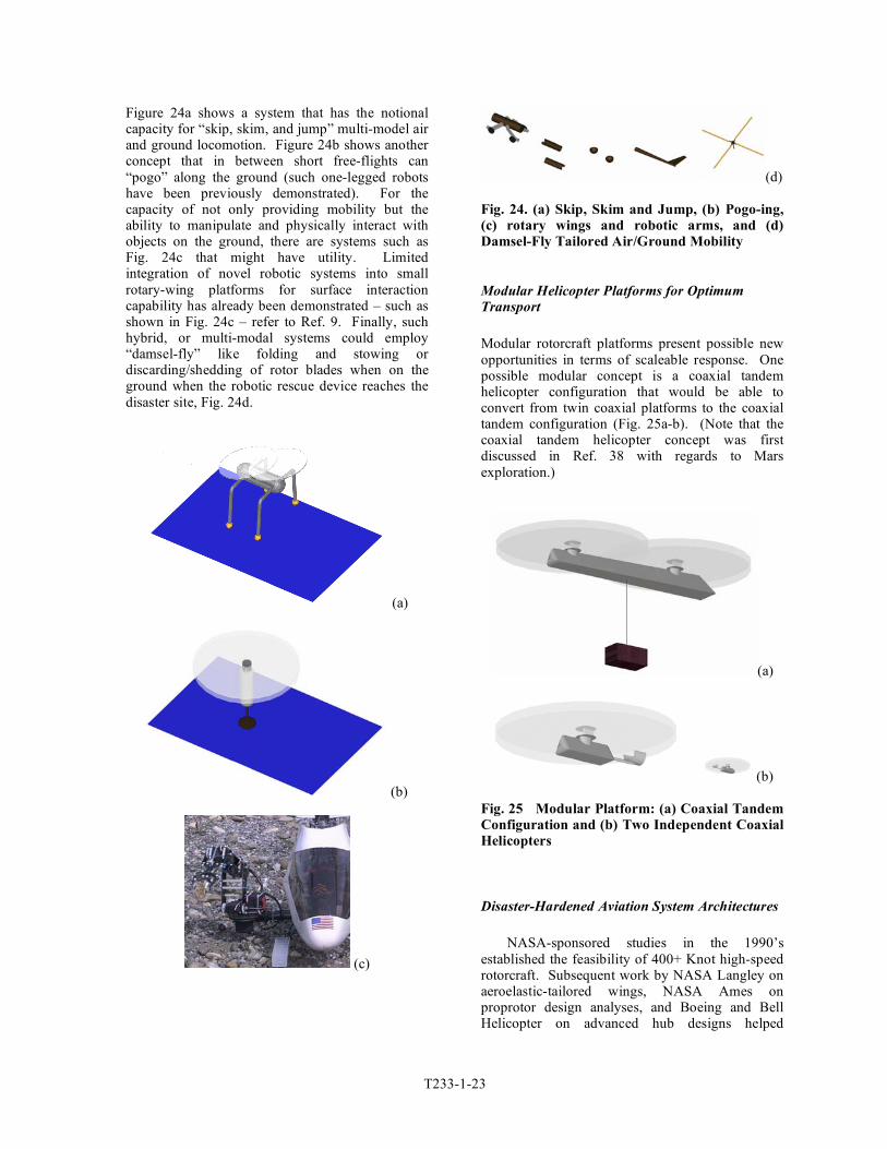
distribution of goods and services. Aerobots as a class of vehicles may test the boundaries of aircraft design. Because of their potential ubiquitous, integral nature for future society, they will also potentially serve as powerful (dual-use) aerial platforms/systems supporting disaster relief and emergency response efforts. For example, a small autonomous package delivery aerial platform could theoretically be “reprogrammed”/redirected with great efficacy to support critical high-value medical supplies to emergency field sites. Reference 5 discusses the potential, and challenges, of aerobots in considerable detail. Fig. 23 shows one notional aerobot concept that has potential for search and rescue missions. Practical usage of such aerial robotic systems are not that far in the future, e.g. Ref. 37.
(a)
(b) Fig. 23. “Fractal-Flyer” aerobot: (a) cruise (collective) configuration and (b) resultant swarm of individual fliers
Hybrid/Multi-Modal Robotic Rescue Devices
For many missions in support of disaster relief
efforts it is not sufficient for aerial platform to merely conduct surveys from the air it is equally important (or more so) to conduct “surface interactive” functions, i.e. to do something tangible and productive on the ground. To best effect such functions it might be necessary to consider robotic rescue devices that have hybrid or multi-modal capacities. Figure 24a-c illustrates a few concepts as to such hybrid/multi-modal robotic systems.
T233-1-23
Figure 24a shows a system that has the notional capacity for “skip, skim, and jump” multi-model air and ground locomotion. Figure 24b shows another concept that in between short free-flights can “pogo” along the ground (such one-legged robots have been previously demonstrated). For the capacity of not only providing mobility but the ability to manipulate and physically interact with objects on the ground, there are systems such as Fig. 24c that might have utility. Limited integration of novel robotic systems into small rotary-wing platforms for surface interaction capability has already been demonstrated – such as shown in Fig. 24c – refer to Ref. 9. Finally, such hybrid, or multi-modal systems could employ “damsel-fly” like folding and stowing or discarding/shedding of rotor blades when on the ground when the robotic rescue device reaches the disaster site, Fig. 24d.
(a)
(b)
(c)
(d)
Fig. 24. (a) Skip, Skim and Jump, (b) Pogo-ing, (c) rotary wings and robotic arms, and (d) Damsel-Fly Tailored Air/Ground Mobility
Modular Helicopter Platforms for Optimum
Transport
Modular rotorcraft platforms present possible new opportunities in terms of scaleable response. One possible modular concept is a coaxial tandem helicopter configuration that would be able to convert from twin coaxial platforms to the coaxial tandem configuration (Fig. 25a-b). (Note that the coaxial tandem helicopter concept was first discussed in Ref. 38 with regards to Mars exploration.)
(a)
(b)
Fig. 25 Modular Platform: (a) Coaxial Tandem Configuration and (b) Two Independent Coaxial Helicopters
Disaster-Hardened Aviation System Architectures
NASA-sponsored studies in the 1990’s
established the feasibility of 400+ Knot high-speed rotorcraft. Subsequent work by NASA Langley on aeroelastic-tailored wings, NASA Ames on proprotor design analyses, and Boeing and Bell Helicopter on advanced hub designs helped
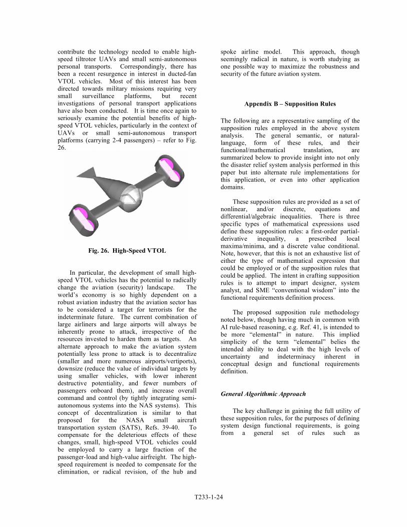
T233-1-24
contribute the technology needed to enable high-speed tiltrotor UAVs and small semi-autonomous personal transports. Correspondingly, there has been a recent resurgence in interest in ducted-fan VTOL vehicles. Most of this interest has been directed towards military missions requiring very small surveillance platforms, but recent investigations of personal transport applications have also been conducted. It is time once again to seriously examine the potential benefits of high-speed VTOL vehicles, particularly in the context of UAVs or small semi-autonomous transport platforms (carrying 2-4 passengers) – refer to Fig. 26.
Fig. 26. High-Speed VTOL In particular, the development of small high-
speed VTOL vehicles has the potential to radically change the aviation (security) landscape. The world’s economy is so highly dependent on a robust aviation industry that the aviation sector has to be considered a target for terrorists for the indeterminate future. The current combination of large airliners and large airports will always be inherently prone to attack, irrespective of the resources invested to harden them as targets. An alternate approach to make the aviation system potentially less prone to attack is to decentralize (smaller and more numerous airports/vertiports), downsize (reduce the value of individual targets by using smaller vehicles, with lower inherent destructive potentiality, and fewer numbers of passengers onboard them), and increase overall command and control (by tightly integrating semi-autonomous systems into the NAS systems). This concept of decentralization is similar to that proposed for the NASA small aircraft transportation system (SATS), Refs. 39-40. To compensate for the deleterious effects of these changes, small, high-speed VTOL vehicles could be employed to carry a large fraction of the passenger-load and high-value airfreight. The high-speed requirement is needed to compensate for the elimination, or radical revision, of the hub and
spoke airline model. This approach, though seemingly radical in nature, is worth studying as one possible way to maximize the robustness and security of the future aviation system.
Appendix B – Supposition Rules The following are a representative sampling of the supposition rules employed in the above system analysis. The general semantic, or natural-language, form of these rules, and their functional/mathematical translation, are summarized below to provide insight into not only the disaster relief system analysis performed in this paper but into alternate rule implementations for this application, or even into other application domains.
These supposition rules are provided as a set of
nonlinear, and/or discrete, equations and differential/algebraic inequalities. There is three specific types of mathematical expressions used define these supposition rules: a first-order partial-derivative inequality, a prescribed local maxima/minima, and a discrete value conditional. Note, however, that this is not an exhaustive list of either the type of mathematical expression that could be employed or of the supposition rules that could be applied. The intent in crafting supposition rules is to attempt to impart designer, system analyst, and SME “conventional wisdom” into the functional requirements definition process.
The proposed supposition rule methodology
noted below, though having much in common with AI rule-based reasoning, e.g. Ref. 41, is intended to be more “elemental” in nature. This implied simplicity of the term “elemental” belies the intended ability to deal with the high levels of uncertainty and indeterminacy inherent in conceptual design and functional requirements definition.
General Algorithmic Approach
The key challenge in gaining the full utility of
these supposition rules, for the purposes of defining system design functional requirements, is going from a general set of rules such as

T233-1-25
!
"
"Ai•
P K( ) > 0 or < 0,"
"Ai•
P K( ) = 0 while "2
"Ai•2
P K( ) < 0 or > 0
for a range of values for Ai•, If f Ai
•# $ % &
' ( =True
to implicitly solving for the function
!
P K,Ai•,K
" # $ %
& ' .
In general this is no trivial exercise. Given some of the unique aspects of supposition rules employed, the proposed algorithmic solution approach for defining
!
P K,Ai•,K
" # $ %
& ' for a select set of attributes
!
A• (for each given concept for each given societal
good objective) is as follows: 1. Assume limits have been pre-defined for
each attribute
!
Ai• such that
!
ail " Ai•" aiu and
!
pil "P K( ) " piu . Typically
!
pil = 0 and
!
piu = 1 (negligible to high confidence in a given concept accomplishing a given objective).
2. For supposition rules having the form of
first-order partial-derivative inequalities, the following
(a)
!
"
"Ai•
P K( ) > 0
Therefore, given the level of indeterminacy inherent in supposition rules of this form, this dictates (for this single instance of a rule affecting the attribute
!
Ai•) that
!
Ai•
Rule #n
= aiu
Collectively, though, multiple instances of rules, as will be seen later, will profoundly affect the final value of
!
Ai• and
!
P K( ) .
(b)
!
"
"Ai•
P K( ) < 0
For the above case, then
!
Ai•
Rule #n
= ail
3. For supposition rules having the form of
prescribed local maxima/minima
!
"
"Ai•
P K( ) = 0 while
!
"2
"Ai
•2P K( ) < 0 or > 0
Therefore, given the level of indeterminacy inherent in supposition rules of this form, the “best” (given the circumstances) solution and logic dictates (for this single instance of a rule affecting the attribute
!
Ai•) that
!
Ai•
Rule #t
= aiu + ail( ) 2
4. Then, given the above, the “best” possible
solution for
!
Ai• given the inherent
indeterminacy of the supposition rules employed is
!
Ai•
= mean Ai•
Rule #n
,K,Ai•
Rule #t
"
# $
%
& '
For all pertinent supposition rules affected by the attribute
!
Ai• ; for all attributes
influenced by supposition rules of types one and two (first-order partial-derivative inequalities and prescribed local maxima/minima). The above expression assumes equal weighting between the various pertinent supposition rules for
!
Ai• ;
this is not an absolute requirement, different weightings (both static and dynamic) could be implemented, if necessary, so as to arrive at a weighted mean average for
!
Ai• .
5. For supposition rules having the form of
discrete value conditionals (a)
!
If Ai•" aiu Then An
•= b2 Else An
•= b1
Where as before
!
ail " Ai•" aiu and
!
b1 and
!
b2 are constants assigned in the
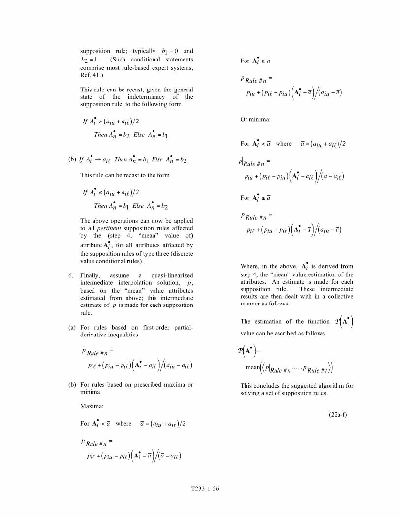
T233-1-26
supposition rule; typically
!
b1 = 0 and
!
b2 = 1 . (Such conditional statements comprise most rule-based expert systems, Ref. 41.)
This rule can be recast, given the general state of the indeterminacy of the supposition rule, to the following form
!
If Ai• > aiu + ail( ) 2
Then An• = b2 Else An
• = b1
(b)
!
If Ai•" ail Then An
•= b1 Else An
•= b2
This rule can be recast to the form
!
If Ai•" aiu + ail( ) 2
Then An• = b1 Else An
• = b2
The above operations can now be applied to all pertinent supposition rules affected by the (step 4, “mean” value of) attribute
!
Ai• , for all attributes affected by
the supposition rules of type three (discrete value conditional rules).
6. Finally, assume a quasi-linearized
intermediate interpolation solution,
!
p , based on the “mean” value attributes estimated from above; this intermediate estimate of
!
p is made for each supposition rule.
(a) For rules based on first-order partial-
derivative inequalities
!
pRule #n
=
pil + piu " pil( ) Ai• " ail
# $ % &
' ( aiu " ail( )
(b) For rules based on prescribed maxima or
minima Maxima: For
!
Ai•
< a where
!
a " aiu + ail( ) 2
!
pRule #n
=
pil + piu " pil( ) Ai• " a
# $ % &
' ( a " ail( )
For
!
Ai•" a
!
pRule #n
=
piu + pil " piu( ) Ai• " a
# $ % &
' ( aiu " a ( )
Or minima: For
!
Ai•
< a where
!
a " aiu + ail( ) 2
!
pRule #n
=
piu + pil " piu( ) Ai• " ail
# $ % &
' ( a " ail( )
For
!
Ai•" a
!
pRule #n
=
pil + piu " pil( ) Ai• " a
# $ % &
' ( aiu " a ( )
Where, in the above,
!
Ai• is derived from
step 4, the “mean" value estimation of the attributes. An estimate is made for each supposition rule. These intermediate results are then dealt with in a collective manner as follows.
The estimation of the function
!
P A•"
# $ %
& '
value can be ascribed as follows
!
P A•"
# $ %
& ' =
mean pRule #n
,K, pRule #t( )
This concludes the suggested algorithm for solving a set of supposition rules.
(22a-f)
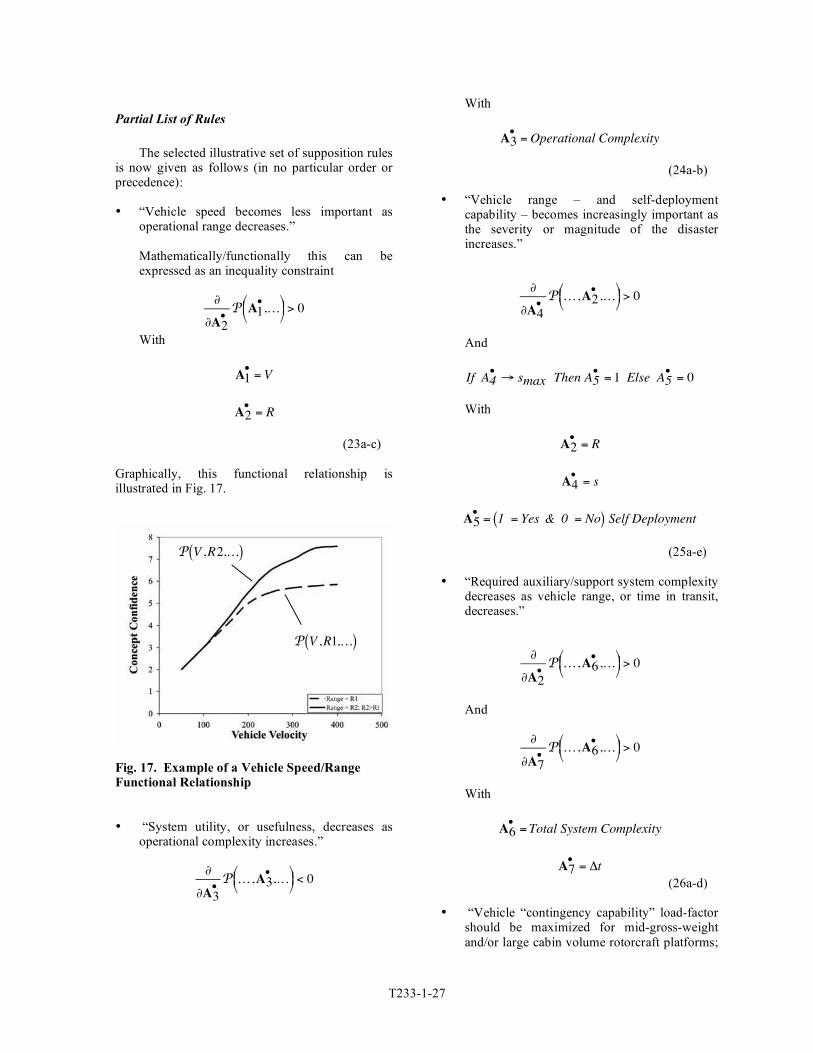
T233-1-27
Partial List of Rules
The selected illustrative set of supposition rulesis now given as follows (in no particular order orprecedence):
• “Vehicle speed becomes less important asoperational range decreases.”
Mathematically/functionally this can beexpressed as an inequality constraint
!
"
"A2•
P A1•,K
#$% &
'( > 0
With
!
A1•
= V
!
A2•
= R
(23a-c)
Graphically, this functional relationship isillustrated in Fig. 17.
Fig. 17. Example of a Vehicle Speed/RangeFunctional Relationship
• “System utility, or usefulness, decreases asoperational complexity increases.”
!
"
"A3•
P K,A3•,K
#$% &
'( < 0
With
!
A3•
= Operational Complexity
(24a-b)
• “Vehicle range – and self-deploymentcapability – becomes increasingly important asthe severity or magnitude of the disasterincreases.”
!
"
"A4•
P K,A2•,K
#$% &
'( > 0
And
!
If A4•" smax Then A5
•= 1 Else A5
•= 0
With
!
A2•
= R
!
A4•
= s
!
A5• = 1 = Yes & 0 = No( ) Self Deployment
(25a-e)
• “Required auxiliary/support system complexitydecreases as vehicle range, or time in transit,decreases.”
!
"
"A2•
P K,A6•,K
#$% &
'( > 0
And
!
"
"A7•
P K,A6•,K
#$% &
'( > 0
With
!
A6•
= Total System Complexity
!
A7•
= "t
(26a-d)
• “Vehicle “contingency capability” load-factorshould be maximized for mid-gross-weightand/or large cabin volume rotorcraft platforms;
!
P V ,R2,K( )
!
P V ,R1,K( )

T233-1-28
the load-factor is allowed to taper off (notionally like a ‘bell-curve’) for smaller or larger gross weight vehicles.”
!
"
"A9•
P K,A8•,K
# $ % &
' ( = 0
And
!
"2
"A9•2
P K,A8•,K
# $ % &
' ( < 0
For some specified range of vehicle gross weight With
!
A8•
= n
!
A9•
=GW (27a-d)
The remaining supposition rules are presented only non-mathematically. • “Aerial vehicle cost increases with increasing
gross weight” • “Aerial vehicle cost increases with increasing
cruise speed” • “System cost increases with increasing system
complexity” • “System reliability is optimized at some
moderate (somewhere in between the system attribute/parametric limits) level of system complexity and intelligence (on one hand more complexity increases probability of system failure, on the other hand, more complexity can mean more system redundancy, fault tolerance, and diagnostic/prognostic monitoring).”
• “System capability generally increases with
increasing system complexity.” • “Acceptable mission risk is directly
proportional to potential number of lives saved and inversely proportional to crew lives put in harms way.”
(Note that this is the key justification or design-driver for the development and usage of autonomous aerial vehicles and robotic rescue devices.)
• If aerial platform and/or rescue
systems/equipment is not self-deployable, then the system must be capable of being air- or ground-transported by some other asset.
The corollary to this rule is that there are volume and mass limits that have to be adhered to for the various modes of transport.
The above list of supposition rules is hardly
exhaustive in nature, even for the disaster relief and emergency response application domain.
References
1Flater, M.E., “Helicopters in Tsunami Relief,” 5th Australian Vertiflite Conference, Melbourne, Australia, March 14, 2005. (Copies available from AHS, International Headquarters.)
2Flater, M.E., “Hurricane Katrina – Helicopters in Disaster Relief,” RAE (Royal Aeronautical Society’s) Conference on Aviation in Support of Humanitarian and Disaster Relief Operations, London, October 31, 2006. (Copies available from AHS, International Headquarters.)
3Young, L.A., Yetter, J.A., and Guynn, M.D., “System Analysis Applied to Autonomy: Application to High-Altitude Long-Endurance Remotely Operated Aircraft,” AIAA Infotech@Aerospace Conference, Arlington, VA, September 2005.
4Young, L.A., “System Analysis Applied to Autonomy: Application to Human-Rated Lunar/Mars Landers,” AIAA Space 2006 Conference, San Jose, CA, September 19-21, 2006.
5Young, L.A., “Aerobots as a Ubiquitous Part of Society,” AHS Vertical Lift Aircraft Design (VLAD) Conference, San Francisco, CA, January 18-20, 2006.
6Aiken, E.W., Ormiston, R.A., and Young, L.A., “Future Directions in Rotorcraft Technology at Ames Research Center,” 56th Annual Forum of the American Helicopter Society, International, Virginia Beach, VA, May 2-4, 2000.
7Young, L.A., Aiken, E.W., Johnson, J.L., Demblewski, R., Andrews, J., and Klem, J., “New Concepts and Perspectives on Micro-Rotorcraft and Small Autonomous Rotary-Wing Vehicles,” AIAA 20th Applied Aerodynamics Conference, St Louis, MO, June 24-27, 2002.
8Pisanich, G. and Young, L.A., “An Aerobot Ecology,” Robosphere 2002: Workshop on Self-

T233-1-29
Sustaining Robot Ecologies, NASA Ames Research Center, Moffett Field, CA, November 2002.
9Young, L.A., Aiken, E.W., and Briggs, G.A., “Smart Rotorcraft Field Assistants for Terrestrial and Planetary Science,” IEEE Aerospace Conference, Big Sky, MT, March 2004.
10Young, L.A. and Pisanich, G., “Aerial Explorers and Robotic Ecologies,” Second International Conference on Computing, Communication and Control Technologies, Austin, TX, August 14-17, 2004.
11Young, L.A., “Small Autonomous Air/Sea System Concepts for Coast Guard Missions,” US Coast Guard Maritime Domain Awareness Requirements, Capabilities, and Technology (MDA RCT) Forum, Santa Clara, CA, May 2, 2005.
12Anonym., “Hyogo Framework for Action 2005-2015: Building the Resilience of Nations and Communities to Disasters,” UN World Conference on Disaster Reduction: http://www.unisdr.org/wcdr/, Kobe, Hyogo, Japan, January 18-22, 2005.
13United Nations Office For the Coordination of Humanitarian Affairs (OCHA), http://www.reliefweb.int/ocha_ol/programs/response/service.html#RCB.
14Anonym., “International Strategy for Disaster Reduction, Disaster Statistics, Occurrence: Trends-Century,” United Nations Publication, http://www.unisdr.org/disaster-statistics/pdf/isdr-disaster-statistics-occurrence.pdf.
15Colby, S., “A Military View of Katrina’s Lessons,” Rotor-Wing Magazine, Vol. 40, No. 6, June 2006, pg. 62.
16Hazdra, R.J., Maj. USAF, “Air Mobility – The Key to the United States National Security Strategy,” Air University Press, Maxwell Air Force Base, Alabama, August 2001.
17Blumen, I.J., et al, “A Safety Review and Risk Assessment in Air Medical Transport,” Air Medical Physician Association, 2002.
18Miyatake, H, and Nunomura, A., “General Overviews and Future Perspectives of Disaster Information Systems in Japan,” http://www.pwri.go.jp/eng/ujnr/joint/35/paper/51miyata.pdf.
19Mashiko, K., “Trauma Systems in Japan: History, Present Status, and Future Perspectives,” Journal of the Nippon Medical School, Vol. 72, No. 4, 2005.
20Anonym., “Integrating Helicopter and Tiltrotor Assets Into Disaster Relief Planning,” FAA Advisory Circular AC No. 00-59, November 13, 1998, http://www.faa.gov/and/AC0059/ACNo0059.htm.
21Davis, D.P., et al, “The Impact of Aeromedical Response to Patients with Moderate to
Severe Traumatic Brain Injury,” Annuals of Emergency Medicine, Vol. 46, No. 2, August 2005, pp. 115-271.
22Bradly, A.P., “Cost-Effectiveness Analysis: an Assessment of its Application in Evaluating Humanitarian Assistance,” CEM99-5, Asia Pacific Press at Australian National University, 1999.
23Sage, A.P., Systems Engineering, Wiley Series in Systems Engineering, John Wiley and Sons, Inc., New York, 1992.
24Lesourne, J., Silvey, A., Trans., Cost-Benefit Analysis and Economic Theory, North-Holland Publishing Co., Amsterdam, 1975.
25Dalkey, N., Brown, B., and Cochran, S., “The Delphi Method, III: Use of Self Ratings to Improve Group Estimates,” RAND Report RM-6115-PR, November 1969.
26Pisanch, G., Young, L.A., Ippolito, C., Plice, L., Lau, B., “Actions, Observations, and Decision-Making: Biologically Inspired Strategies for Autonomous Aerial Vehicles,” AIAA Aerospace Sciences Conference, Intelligent Systems Session, Reno, NV, January 2004.
27Plice, L., Pisanich, G., Lau, B., and Young, L., “Biologically Inspired Behavioral Strategies for Autonomous Aerial Explorers on Mars,” 2003 IEEE Aerospace Conference, Big Sky, MT, March 8-15, 2003.
28Williams, D.R., et al, “A Strategic Vision for Telemedicine and Medical Informatics in Space Flight,” Telemedicine Journal, Volume 6, Winter 2000, pp. 441-8.
29Nicogossian, A.E., et al, “Evolution of Telemedicine in the Space Program and Earth Applications,” Telemedicine Journal, Volume 7, Spring 2001, pp. 1-15.
30Center for Robot-Assisted Search and Rescue (CRASAR), University of South Florida, web site: http://crasar.csee.usf.edu/MainFiles/index.asp.
31Burke, J.L., Murphy, R.R., Coovert, M.D., and Riddle, D.L., “Moonlight in Miami: A Field Study of Human-Robot Interaction in the Context of an Urban Search and Rescue Disaster Response Training Exercise,” Human-Computer Interaction, Volume 19, pp. 85-116, 2004.
32Murphy, R.R., “Rescue Robotics for Homeland Security,” Communications of the ACM, Vol. 47, No. 3, March 2004.
33Murphy, R.R. and Burke, J.L., “Up from the Rubble: Lessons Learned about HRI from Search and Rescue,” Proceedings of the 49th Annual Meetings of the Human Factors and Ergonomics Society, 2005.
34Matthies, L., et al, “A Portable, Autonomous, Urban Reconnaissance Robot,” International Conference on Intelligent Autonomous Systems, Venice, Italy, July 25, 2000.
T233-1-30
35Belov, A., et al, “Mil Helicopters in the Chernobyl Disaster,” 59th Annual Forum of the American Helicopter Society, Phoenix, AZ, May 6-9, 2003.
36Tishchenko, M.N., Nagaraj, V.T., and Chopra, I., “Unmanned Transport Helicopters,” 55th Annual Forum of the American Helicopter Society, Montreal, Canada, May 25-27, 1999.
37Caltabiano, D., et al, “Architecture of a UAV for Volcanic Gas Sampling,” 10th IEEE Conference on Emerging Technologies and Factory Automation, 2005. (ETFA 2005), Sept. 19-22, 2005.
38Young, L.A., Aiken, E.W., Briggs, G.A., and Lee, P., “Mars Rotorcraft: Possibilities, Limitations, and Implications for Human/Robotic Exploration,” IEEE Aerospace Conference, Big Sky, MT, March 2005.
39Holmes, B.J., et al, “Small Aircraft Transportation System Concept and Technologies,” AIAA Journal of Aircraft, Volume 41, 2005.
40Vicken, S.A., et al, “Overview of the Small Aircraft Transportation System Project – Four Enabling Operating Capabilities,” AIAA 5th Aviation Technology, Integration, and Operations Conference (ATIO), AIAA CP 2005-7312, Arlington, VA, Sept. 26-28, 2005.
41Cawsey, A., The Essence of Artificial Intelligence, Essence of Computing Series, Prentice Hall, 1998.
42Zuk, J. and Adams, R.J.: "I. Summary. Helicopter Technology Needs, Public Service Helicopter Users' Workshop", NASA CR-166143, July 1980.
43Zuk, J. and Adams, R.J.: "II. Appendices. Helicopter Technology Needs, Public Service Helicopter Users' Workshop", NASA CR-166144. July 1980.