futurebuild lvl specific engineering design guide · 2019-08-20 · futurebuild® lvl specific...
TRANSCRIPT
FUTUREBUILD® LVL SPECIFIC ENGINEERING DESIGN GUIDEA U G U S T 2 0 1 9
Information contained within is specific to the Futurebuild® LVL range of products and must not be used with any other LVL products no matter how similar they may appear.

FUTUREBUILD® LVL SPECIFIC ENGINEERING DESIGN GUIDE
Contents1.0 Laminated Veneer Lumber ............................ 31.1 Futurebuild® LVL .............................................. 31.2 Residential Buildings ....................................... 41.3 Commercial & Industrial Buildings ............... 41.4 Engineering Design Tools ............................... 41.5 Futurebuild LVL Product Range .................... 61.6 Grades ............................................................... 61.7 Cross Banded Futurebuild LVL (X-Band) .... 61.8 Purlin Design .................................................... 61.9 Made to Order I-Beam ................................... 71.10 Pre-Fabrication Network ............................... 71.11 Non Standard Sizes & Lengths ...................... 71.12 Futurebuild LVL Specifications ...................... 72.0 General Design Considerations .................... 82.1 Characteristic Stresses ................................... 8
2.2 Strength Reduction Factor Ø ...................... 82.3 Duration of Load Factor ................................ 82.4 Bearing Area ..................................................... 82.5 Load Sharing .................................................... 92.6 Stability ............................................................. 92.7 Temperature..................................................... 92.8 Moisture Content ............................................ 92.9 Face Grain Angle ............................................. 92.10 Size Factor ........................................................ 92.11 Joint Group ..................................................... 102.12 Fire Resistance ............................................... 103.0 Characteristic Properties ............................. 113.1 Standard Section Sizes &
Characteristic Material Properties ............. 113.2 hySPAN® Limit State Design
Characteristic Properties ............................. 123.3 hy90® Limit State Design Characteristic
Properties ....................................................... 133.4 hyONE® Limit State Design
Characteristic Properties ............................. 143.5 hyCHORD® Limit State Design Characteristic
Properties ....................................................... 153.6 hyJOIST® Section Geometry ....................... 164.0 References ...................................................... 175.0 Limitations ...................................................... 17

FUTUREBUILD® LVL | FUTUREBUILD® LVL SPECIFIC DESIGN GUIDE | 0800 585 244 | www.futurebuild.co.nz 3
1.0 LAMINATED VENEER LUMBER
Laminated Veneer Lumber (LVL) is an engineered wood material with defined and reliable strength and stiffness properties. It is suited to a wide range of structural applications, including critical elements such as large span portal frames and primary or secondary beams in commercial buildings.
1.1 FUTUREBUILD ® LVL
Manufactured by Futurebuild® LVL in Northland, New Zealand, the Futurebuild LVL range is New Zealand’s largest range of LVL. The Futurebuild LVL range of products features specific material property ‘recipes’. As such the information contained within this literature is specific to the Futurebuild LVL range and must not be used with any other LVL products no matter how similar they may appear.
For designers Futurebuild LVL offers:
• Consistent structural performance with low variability.• Third party certification of conformance with AS/NZS 4357 by the Engineered Wood
Products Association of Australasia (EWPAA)1.• Long lengths and large cross-sectional dimensions.• Dimensionally stable product, which is easily installed on site.1Some products, including non standard I-Joists, may not carry EWPAA certification.
This literature contains general design information and material properties intended for use where members are specifically engineered for applications not covered by Futurebuild LVL product brochures. For design information for standard applications visit www.futurebuild.co.nz.
Futurebuild LVL products must be competently installed in accordance with good building practices and sound design principles to satisfy the requirements of the Building Act 2004, the New Zealand Building Code, and applicable New Zealand Standards. This is the responsibility of building owners and the design professionals and builders that they engage. This document contains information, limitations, and cautions regarding the properties, handling, installation, usage, and the maintenance of Futurebuild LVL products. However, to the maximum extent permitted by law, Futurebuild LVL assumes no legal liability to you in relation to this information.
When specifying or installing any Futurebuild LVL product visit www.futurebuild.co.nz or call 0800 585 244 to ensure you have current specification material and any relevant technical notes.
FUT
UR
EBUILD
® LVL LA
MIN
AT
ED V
ENEER
LUM
BER
The information contained in this document is current as at August 2019. It is your responsibility to ensure you have the most up to date information available.
The information contained in this publication relates specifically to Futurebuild® LVL products manufactured by Carter Holt Harvey LVL Limited and must not be used with any other LVL manufacturer’s product no matter how similar they may appear.
Alternative LVL products can differ in a number of ways which may not be immediately obvious and substituting them for Futurebuild LVL products is not appropriate and could in extreme cases lead to premature failure and/or buildings which do not meet the requirements of the New Zealand Building Code.

FUTUREBUILD® LVL | FUTUREBUILD® LVL SPECIFIC DESIGN GUIDE | 0800 585 244 | www.futurebuild.co.nz4
FUT
UR
EBU
ILD
® L
VL
LAM
INA
TED
VEN
EER
LU
MBE
R1.2 RES IDENTIAL BUILDINGS
Software for the design of members for use in residential construction can be downloaded from www.chhsoftware.co.nz.
1.2.1 designIT® for houses
designIT® for houses is a tool for building industry professionals involved in designing houses and similar structures using the Futurebuild® LVL range of engineered wood products and other selected materials. Quick and simple to use, subject to the terms of a licence agreement, the deceptively powerful designIT software is useful for the selection of beam sizes.
1.2.2 layITout® for houses
layITout® for houses is an integrated design and layout tool that allows users to enter a house plan, propose, and then design a floor joist or rafter layout for a fully integrated engineered system.
1.2.3 designIT site
designIT site is a smartphone app developed as a handy reference tool for the specifier or tradesman on the go. The designIT site app is a trimmed down version of designIT for houses.
1.2.4 floorIT site
floorIT site is a smartphone app to aid specifiers in the specification, selection and estimation of quantities for a range of flooring applications.
1.3 COMMERCIAL & INDUSTRIAL BUILDINGS
The Preliminary Design Service is an LVL focused initiative to provide design tools and specialised products for the development of portal frame structures using the Futurebuild LVL range of products. Futurebuild LVL solutions include software platforms, engineering design tools and advice, a commercial product range and a network of experienced
pre-fabricators to provide cost effective LVL portal frames to the market.
To access the tools below visit www.chhsoftware.co.nz or call 0800 585 244 to speak to an experienced timber design engineer.
1.4 ENGINEERING DESIGN TOOLS
The following design tools are available for the Futurebuild LVL range.
1.4.1 Fully Worked Design Example
A fully worked design example of a portal frame structure including design computations, standards references and design and practical application tips. This example covers member design and specification, connections to and from secondary and primary framing members and lateral support components.
1.4.2 Engineering Support
We have an in-house engineering team consisting of Chartered Professional Engineers with many years of combined consultancy experience with an emphasis on Timber Engineering. They are available to speak to you about issues ranging from design and specification to the suitability of details for fabrication and erection advice.
1.4.3 computeIT® Software Suite
The computeIT® software suite consists of software packages; computeIT for beams and computeIT toolkIT. It is designed to aid in the specification of heavy structural members and non-residential structural systems. It enables engineers, even those unfamiliar with the specifics of timber engineering to produce high quality, reliable specifications.

FUTUREBUILD® LVL | FUTUREBUILD® LVL SPECIFIC DESIGN GUIDE | 0800 585 244 | www.futurebuild.co.nz 5
1.4.4 computeIT® for beams
computeIT® for beams is a beam analysis package that enables engineers to develop design solutions for a range of engineered wood products, including Timber Concrete Composite (TCC) Floors design using EXPAN® technology to provide composite action between concrete and Laminated Veneer Lumber (LVL). Developed by engineers for engineers, computeIT for beams allows engineers the flexibility of making design decisions using LVL based structural solutions. computeIT for beams provides users with an easy to use interface that allows engineers to:
• Enter complex beam design situations, including statically indeterminate beams and cantilevers.
• Enter a number of different load types including point loads, UDL’s and trapezoidal/triangular loads.
• Enter beam restraint information for calculation of capacities in accordance with AS 1720.1:2010.
• Make engineering decisions based on engineering outputs including, deflection, bending moment and shear force diagrams.
• Design connections using a number of common connection details.
• Analyse a number of different members to produce cost effective design solutions.
• View graphical representations of beam geometry, loading and design action effect diagrams.
• Select loading combinations to AS/NZS 1170.• Apply design actions from other members within a job.• Create a job specific Engineering Analysis Report including
designed members and connections.• Optimise TCC Floor design using all three shear connections:
trapezoidal notch with coach bolts, triangular notch with coach bolts and an un-notched shear connector using angled SFS screws.
1.4.5 computeIT toolkIT
computeIT toolkIT is a series of design tools to allow engineers the flexibility to quickly and easily design solid and box section structural beam and column members including moment resisting connections, beam and column members subject to combined actions, and purlins and girts.
Included in the computeIT toolkIT is Expan Quick Connect moment resisting connection design technology. The Quick Connect technology uses a threaded rod, washers and nuts for easy connection on site through factory fitted LVL sleeves. It also provides engineers with alternate moment resisting connections such as nail and screw rings used in portal frame solutions.
Developed by experienced timber design engineers using the most up to date information from design standards, the computeIT toolkIT provides users with the opportunity to:
• Design moment resisting connections with commonly available materials and connectors.
• Design solid and built up members subject to combined actions easily, considering the effects of alternate restraint options.
• Select loading combinations for analysis to AS/NZS 1170, with automatic selection of duration of load factor.
• Analyse different members to determine cost effective options• Design solid and i-beam purlins and girts, including support and
restraint details.• Create a job specific Engineering Analysis Report including
designed members and connections.
1.4.6 designIT® for commercial floors
designIT® for commercial floors gives building industry professionals a tool for designing commercial, industrial and other heavily loaded floors with the Futurebuild® LVL range of engineered wood products and other selected materials.
computeIT ToolkIT: Composite Member Design.
computeIT® for Beams: TCC Floor Design - Analysis and Design.
FUT
UR
EBUILD
® LVL LA
MIN
AT
ED V
ENEER
LUM
BER
FUTUREBUILD® LVL | FUTUREBUILD® LVL SPECIFIC DESIGN GUIDE | 0800 585 244 | www.futurebuild.co.nz6
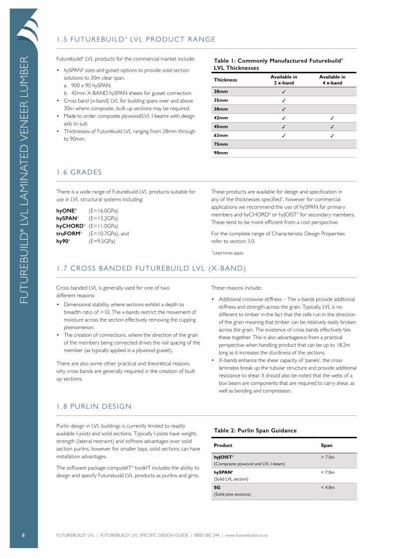
1.5 FUTUREBUILD ® LVL PRODUCT RANGE
Futurebuild® LVL products for the commercial market include:
• hySPAN® sizes and gusset options to provide solid section solutions to 30m clear span.a. 900 x 90 hySPAN. b. 42mm X-BAND hySPAN sheets for gusset connection.
• Cross band (x-band) LVL for building spans over and above 30m where composite, built up sections may be required.
• Made to order composite plywood/LVL I-beams with design aids to suit.
• Thicknesses of Futurebuild LVL ranging from 28mm through to 90mm.
Table 1: Commonly Manufactured Futurebuild® LVL Thicknesses
ThicknessAvailable in
2 x-bandAvailable in
4 x-band
28mm 3
35mm 3
38mm 3
42mm 3 3
45mm 3 3
63mm 3 3
75mm
90mm
1.6 GRADES
There is a wide range of Futurebuild LVL products suitable for use in LVL structural systems including:
hyONE® (E=16.0GPa) hySPAN® (E=13.2GPa)hyCHORD® (E=11.0GPa)truFORM® (E=10.7GPa), and hy90® (E=9.5GPa)
These products are available for design and specification in any of the thicknesses specified1, however for commercial applications we recommend the use of hySPAN for primary members and hyCHORD® or hyJOIST® for secondary members. These tend to be more efficient from a cost perspective.
For the complete range of Characteristic Design Properties refer to section 3.0.
1Lead times apply.
1.7 CROSS BANDED FUTUREBUILD LVL (X-BAND)
Cross banded LVL is generally used for one of two different reasons:
• Dimensional stability, where sections exhibit a depth to breadth ratio of >10. The x-bands restrict the movement of moisture across the section effectively removing the cupping phenomenon.
• The creation of connections, where the direction of the grain of the members being connected drives the nail spacing of the member (as typically applied in a plywood gusset).
There are also some other practical and theoretical reasons why cross bands are generally required in the creation of built up sections.
These reasons include:
• Additional crosswise stiffness – The x-bands provide additional stiffness and strength across the grain. Typically, LVL is no different to timber in the fact that the cells run in the direction of the grain meaning that timber can be relatively easily broken across the grain. The existence of cross bands effectively ties these together. This is also advantageous from a practical perspective when handling product that can be up to 18.2m long as it increases the sturdiness of the sections.
• X-bands enhance the shear capacity of ‘panels’, the cross laminates break up the tubular structure and provide additional resistance to shear. It should also be noted that the webs of a box beam are components that are required to carry shear, as well as bending and compression.
1.8 PURLIN DESIGN
Purlin design in LVL buildings is currently limited to readily available I-joists and solid sections. Typically I-joists have weight, strength (lateral restraint) and stiffness advantages over solid section purlins, however for smaller bays, solid sections can have installation advantages.
The software package computeIT® toolkIT includes the ability to design and specify Futurebuild LVL products as purlins and girts.
Table 2: Purlin Span Guidance
Product Span
hyJOIST® (Composite plywood and LVL I-beam)
> 7.0m
hySPAN® (Solid LVL section)
< 7.0m
SG (Solid pine sections)
< 4.8m
FUT
UR
EBU
ILD
® L
VL
LAM
INA
TED
VEN
EER
LU
MBE
R

FUTUREBUILD® LVL | FUTUREBUILD® LVL SPECIFIC DESIGN GUIDE | 0800 585 244 | www.futurebuild.co.nz 7
1.9 MADE TO ORDER I -BEAM
Futurebuild® LVL has the ability to provide made to order composite plywood/LVL I-beam. The standard hyJOIST® range was developed to target use in floor joists in houses with purlin
spans up to 10.0m. hyJOIST may not be suitable for purlin spans above 10.0m. Contact us for more information.
1.10 PRE-FABRICATION NETWORK
Pre-fabricators develop cost effective supply solutions using the Futurebuild LVL range (including specific design products) in 100mm increments.
Contact us to discuss your options.
1.11 NON STANDARD S IZES & LENGTHS
For commercial quantities, specific engineering designed product can be manufactured in sections up to 1200mm deep in thicknesses from 28mm thick through to 90mm thick, and in lengths up to 18.2m long. Practical limitations apply to the supply
of product such as limiting cupping by keeping depth to breadth ratios at a maximum of 10 for non-cross banded LVL. Minimum order quantities and larger lead times apply to non-standard product. Contact us for more information.
1.12 FUTUREBUILD ® LVL RANGE SPECIF ICATIONS
Futurebuild LVL products are manufactured in accordance with AS/NZS 4357 and have the structural design properties specified in Tables 7, 9, 11 and 13. The following information relates to general Futurebuild LVL production.
Table 3: Veneer Structural Design Properties
Veneer Properties
Thickness 3-4mm
Joints Face Scarf
Joints Other Lap/Scarf
Moisture
Moisture Content at Time of Leaving Mill 8-15%
Nominal Dimensional Tolerances
Depth -0mm, + 2mm
Thickness (<90) -0mm, + 2mm
Thickness (>_ 90) -2mm, + 2mm
Mass
Mass (approximate) 600kg/m3
Adhesive & Bond
Refer AS/NZS 2098 & AS 2754 Phenolic adhesive Type “A” (marine) bond
FUT
UR
EBUILD
® LVL LA
MIN
AT
ED V
ENEER
LUM
BER

FUTUREBUILD® LVL | FUTUREBUILD® LVL SPECIFIC DESIGN GUIDE | 0800 585 244 | www.futurebuild.co.nz8
2.0 GENERAL DESIGN CONSIDERATIONS
Design responsibility relies with the building owner and the professionals that the owner engages. The Specifier for the project must ensure that Futurebuild® LVL is an appropriate
product for their individual project. The Specifier must also provide their own specific design or detailing for any areas that fall outside the scope and specifications of this literature.
2.1 CHARACTERISTIC STRESSES
The Futurebuild LVL characteristic stresses published are determined in accordance with Section 4 of AS/NZS 4063.2:2010 and so comply with the provisions of the New Zealand Building Code through clause 2.3, and further noted in commentary clause C2.3 in NZS 3603.
Note that:
• Characteristic Stresses may be different for use on flat or on edge as detailed.
• Modules of Elasticity (MOE) is a mean value which includes an allowance for shear deformation.
• Because of the low variability of LVL a lower bound E is not required for most applications, however where required, the lower 5th percentile Modulus of Elasticity may be taken as 0.85 E.
• Selection of Characteristics Stress Values should take into account the allowance for the representativeness of the sample population, allowance for levels of control of process and quality, amongst other things.
Substitution with similar properties from alternate manufacturers may not provide the calculated design performance. The characteristic stresses of Futurebuild® LVL products are not for use with products from alternative manufacturers.
2.2 STRENGTH REDUCTION FACTOR Ø
The strength reduction factor for calculating the Design Capacity of Structural Members should be taken from Table 4 below,
extracted from Table 2.1 AS1720.1-2010.
Table 4: Strength Reduction Factors
Structural Timber Material
Application of Structural Member
Category 1 Category 2 Category 3
Structural members for houses for which failure would be unlikely to affect an area1 greater than 25m2;ORSecondary members in structures other than houses
Primary structural members in structures other than houses;ORElements in houses for which failure would be likely to affect an area1 greater than 25m2
Primary structural members in structures intended to fulfil essential services or post disaster function
Value of Strength Reduction Factor Ø
Structural Plywood – AS/NZS 2269.0 0.95 0.85 0.75
Structural Laminated Veneer Lumber – AS/NZS 4357.0 0.95 0.90 0.80
1In this context area should be taken as plan area.
2.3 DURATION OF LOAD FACTOR
Duration of load factors k1 for strength and k2 for stiffness should be as for solid timber in accordance with NZS 3603,
Clause 2.7, Modification factors, k1 and k2 for duration of load.
2.4 BEARING AREA
Bearing area factor k3 is as per NZS 3603.
FUT
UR
EBU
ILD
® L
VL
GEN
ERA
L D
ESIG
N C
ON
SID
ERA
TIO
NS
FUTUREBUILD® LVL | FUTUREBUILD® LVL SPECIFIC DESIGN GUIDE | 0800 585 244 | www.futurebuild.co.nz 9
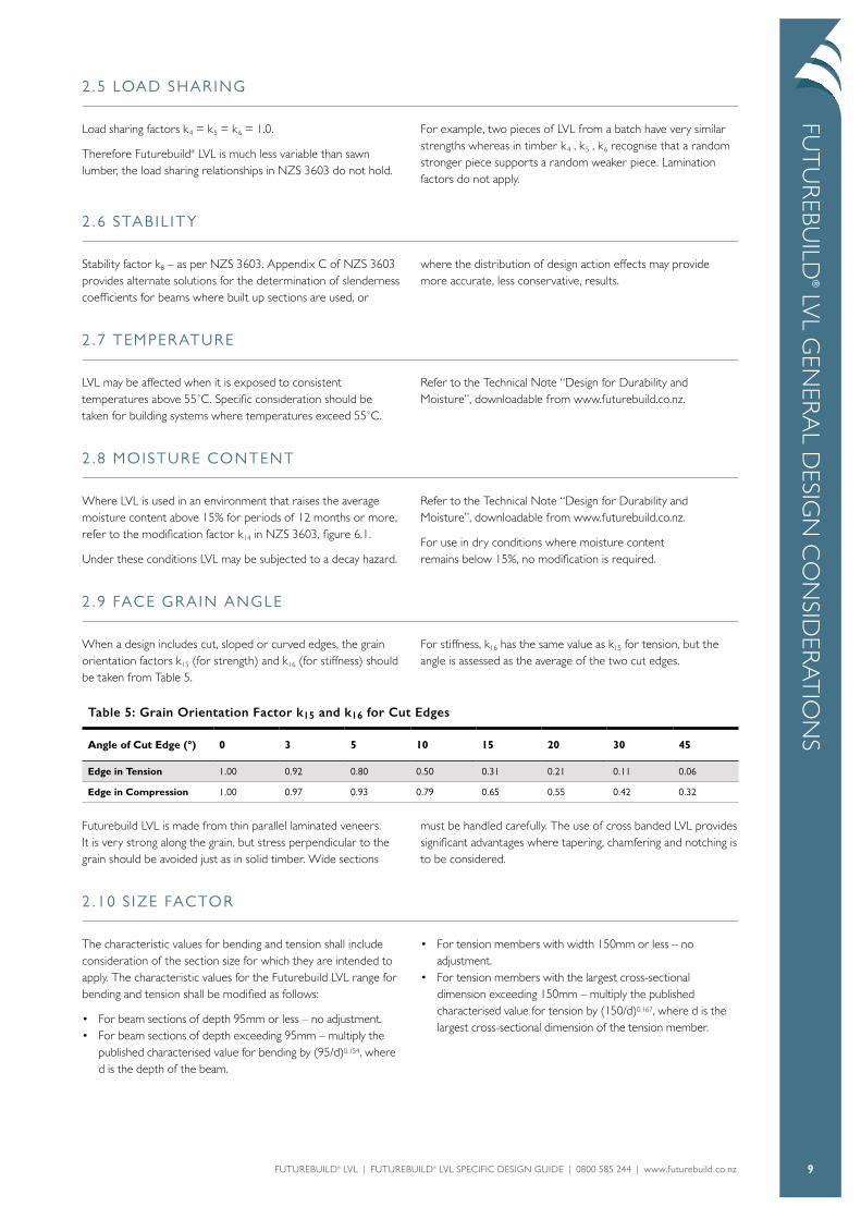
2.5 LOAD SHARING
Load sharing factors k4 = k5 = k6 = 1.0.
Therefore Futurebuild® LVL is much less variable than sawn lumber, the load sharing relationships in NZS 3603 do not hold.
For example, two pieces of LVL from a batch have very similar strengths whereas in timber k4 , k5 , k6 recognise that a random stronger piece supports a random weaker piece. Lamination factors do not apply.
2.6 STABIL ITY
Stability factor k8 – as per NZS 3603. Appendix C of NZS 3603 provides alternate solutions for the determination of slenderness coefficients for beams where built up sections are used, or
where the distribution of design action effects may provide more accurate, less conservative, results.
2.7 TEMPERATURE
LVL may be affected when it is exposed to consistent temperatures above 55˚C. Specific consideration should be taken for building systems where temperatures exceed 55˚C.
Refer to the Technical Note “Design for Durability and Moisture”, downloadable from www.futurebuild.co.nz.
2.8 MOISTURE CONTENT
Where LVL is used in an environment that raises the average moisture content above 15% for periods of 12 months or more, refer to the modification factor k14 in NZS 3603, figure 6.1.
Under these conditions LVL may be subjected to a decay hazard.
Refer to the Technical Note “Design for Durability and Moisture”, downloadable from www.futurebuild.co.nz.
For use in dry conditions where moisture content remains below 15%, no modification is required.
2.9 FACE GRAIN ANGLE
When a design includes cut, sloped or curved edges, the grain orientation factors k15 (for strength) and k16 (for stiffness) should be taken from Table 5.
For stiffness, k16 has the same value as k15 for tension, but the angle is assessed as the average of the two cut edges.
Table 5: Grain Orientation Factor k15 and k16 for Cut Edges
Angle of Cut Edge (°) 0 3 5 10 15 20 30 45
Edge in Tension 1.00 0.92 0.80 0.50 0.31 0.21 0.11 0.06
Edge in Compression 1.00 0.97 0.93 0.79 0.65 0.55 0.42 0.32
Futurebuild LVL is made from thin parallel laminated veneers. It is very strong along the grain, but stress perpendicular to the grain should be avoided just as in solid timber. Wide sections
must be handled carefully. The use of cross banded LVL provides significant advantages where tapering, chamfering and notching is to be considered.
2.10 S IZE FACTOR
The characteristic values for bending and tension shall include consideration of the section size for which they are intended to apply. The characteristic values for the Futurebuild LVL range for bending and tension shall be modified as follows:
• For beam sections of depth 95mm or less – no adjustment.• For beam sections of depth exceeding 95mm – multiply the
published characterised value for bending by (95/d)0.154, where d is the depth of the beam.
• For tension members with width 150mm or less – no adjustment.
• For tension members with the largest cross-sectional dimension exceeding 150mm – multiply the published characterised value for tension by (150/d)0.167, where d is the largest cross-sectional dimension of the tension member.
FUT
UR
EBUILD
® LVL G
ENER
AL D
ESIGN
CO
NSID
ERA
TIO
NS

FUTUREBUILD® LVL | FUTUREBUILD® LVL SPECIFIC DESIGN GUIDE | 0800 585 244 | www.futurebuild.co.nz10
2.11 JOINT GROUP
The joint strength group is dependent on the Futurebuild® LVL product, the type of fastener and the grain orientation at the joint.
Table 6 is to be read in conjunction with NZS 3603 Table 4.1: Classification of timber species for joint design.
Table 6: Classification of LVL Products for Joint Design
ProductNails & Screws in Lateral Load
Type 17 Screws in Lateral Load
Nails & Screws in Withdrawal
Type 17 Screws in Withdrawal
Bolts & Coach Screws in Lateral Load Driven into Face
Edge Face Edge & Face Parallel to Grain
Perpendicular to Grain
hyONE® J5 J4 J4 J4 J3 J3 J1
hySPAN® J5 J4 J4 J4 J3 J3 J1
hyCHORD® J5 J4 J4 J4 J3 J3 J2
hy90® J5 J4 J4 J4 J4 J4 J3
hyJOIST® (flange) J5 J4 J4 J4 not suitable
The higher performing joint strength groups for Futurebuild LVL are due to the interlocking effect of adjacent veneers aligned at small angles.
2.12 F IRE RES ISTANCE
The method for calculating the fire resistance of LVL products is described in NZS 3603 section 9. This method is applicable for sections at least 90mm in all dimensions. Recommendations derived from a testing programme on Futurebuild LVL at the University of Canterbury are:
• The design method used for predicting the fire performance of Futurebuild LVL exposed to post-flashover fires is to use the experimentally found char rate = 0.72mm/minute to determine a reduced cross-section, and design using normal
temperature properties without considering a heat-affected layer of wood below the char line.
• Design using the char rate = 0.65mm/minute (complying with NZS 3603) to calculate a reduced cross section which can be used with normal temperature properties, with an allowance for a 7.5mm zero-strength layer of Futurebuild LVL below the char line.
This data has not been tested on, and is not applicable to LVL made by other manufacturers.
FUT
UR
EBU
ILD
® L
VL
GEN
ERA
L D
ESIG
N C
ON
SID
ERA
TIO
NS

FUTUREBUILD® LVL | FUTUREBUILD® LVL SPECIFIC DESIGN GUIDE | 0800 585 244 | www.futurebuild.co.nz 11
3.0 CHARACTERISTIC PROPERTIES
3.1 STANDARD SECTION S IZES & CHARACTERISTIC MATERIAL PROPERTIES
We manufacture five Futurebuild® LVL product lines for structural applications, each with specific properties and section sizes.
FUT
UR
EBUILD
® LVL C
HA
RA
CT
ERIST
IC PRO
PERTIES
hySPAN® is our most versatile LVL product: it has high structural properties and is available in the largest range of sizes and lengths. hySPAN is typically specified for structural beams and is also used for lintels, rafters and floor joists in residential structures.
hy90® is a LVL product manufactured primarily for lintels or beams to fit within 90mm light timber frame walls. It has lower structural properties than hySPAN but its thickness offers better member stability when used as long span structural beams or columns.
hyONE® is a 90mm thick high stiffness LVL product manufactured primarily for lintels or floor beams where large spans or depth restrictions apply.
hyCHORD® is available in smaller section sizes to match ordinary kiln-dried timber. hyCHORD is primarily specified as roof truss chords, but can also be used for lintels, rafters, purlins, floor joists, wall studs or other members where smaller section sizes are required.
hyJOIST® is an engineered ‘I-beam’ utilising LVL flanges and a plywood web. It is ideally suited to floor joist and rafter applications due to its light weight, straightness and the ability to cut large holes through the web (e.g. for services or ventilation).

FUTUREBUILD® LVL | FUTUREBUILD® LVL SPECIFIC DESIGN GUIDE | 0800 585 244 | www.futurebuild.co.nz12
FUT
UR
EBU
ILD
® L
VL
CH
AR
AC
TER
IST
IC P
ROPE
RTIE
S3.2 h ySPAN ® L IMIT STATE DESIGN CHARACTERISTIC PROPERTIES
Table 7: Characteristic Limit State Design Stresses and Elastic Moduli for hySPAN®
PropertyEdgeMPa
FlatMPa
Modulus Of Elasticity E 13,200 13,200
Modulus Of Rigidity G 660 660
Bending fb1 50.0 42.0
Tension Parallel to Grain ft2 30.0 30.0
Compression Parallel to Grain fc 42.0 42.0
Shear In Beams fs 4.6 3.5
Bearing Perpendicular to Grain fp 12.0 12.0
Joint Group See Table 6
Size Factors:1For beams exceeding 95mm – multiply the published characteristic value for bending by (95/d)0.154 where d is the depth of the beam.2For tension members with the largest cross-sectional dimension exceeding 150mm – multiply the published characteristic value for tension by (150/d)0.167, where d is the largest cross sectional dimension of the tension member.
Table 8: hySPAN Section Sizes, Properties and Design Capacities
Dimensions (mm x mm)
Mass (kg/m)
Ixx (106mm4)
Zxx (103mm3)
J (106mm4)
EIx (109Nmm2)
ØfbZx* (kNm)
150 x 45 4.2 12.7 169 3.7 167 7.1
170 x 45 4.7 18.4 217 4.3 243 8.9
200 x 45 5.6 30.0 300 5.2 396 12.0
240 x 45 6.7 51.8 432 6.4 684 16.9
300 x 45 8.4 101 675 8.3 1337 25.5
360 x 45 10.0 175 972 10.1 2309 35.6
400 x 45 11.2 240 1200 11.3 3168 43.3
150 x 63 6.0 17.7 236 9.2 234 9.9
200 x 63 7.8 42.0 420 13.4 554 16.9
240 x 63 9.4 72.6 605 16.7 958 23.6
300 x 63 11.7 142 945 21.7 1871 35.6
360 x 63 14.1 245 1361 26.7 3233 49.9
400 x 63 15.6 336 1680 30.0 4435 60.6
450 x 63 17.6 478 2126 34.2 6315 75.3
600 x 63 23.4 1134 3780 46.7 14969 128.1
* Ø = 0.9, for category 2 applications (Refer to Table 4).
hySPAN® is readily available in lengths up to 13.2 metres. Contact us for availability of non-standard sizes and lengths.

FUTUREBUILD® LVL | FUTUREBUILD® LVL SPECIFIC DESIGN GUIDE | 0800 585 244 | www.futurebuild.co.nz 13
FUT
UR
EBUILD
® LVL C
HA
RA
CT
ERIST
IC PRO
PERTIES
3.3 h y90 ® L IMIT STATE DESIGN CHARACTERISTIC PROPERTIES
Table 9: Characteristic Limit State Design Stresses and Elastic Moduli for hy90®
PropertyEdgeMPa
FlatMPa
Modulus Of Elasticity E 9,500 9,500
Modulus Of Rigidity G 475 475
Bending fb1 34.0 30.0
Tension Parallel to Grain ft2 22.0 22.0
Compression Parallel to Grain fc 36.6 36.6
Shear In Beams fs 4.6 2.6
Bearing Perpendicular to Grain fp 12.0 12.0
Joint Group See Table 6
Size Factors:1For beams exceeding 95mm – multiply the published characteristic value for bending by (95/d)0.154 where d is the depth of the beam.2For tension members with the largest cross-sectional dimension exceeding 150mm – multiply the published characteristic value for tension by (150/d)0.167, where d is the largest cross sectional dimension of the tension member.
Table 10: hy90 Section Sizes, Properties and Design Capacities
Dimensions (mm x mm)
Mass (kg/m)
Ixx (106mm4)
Zxx (103mm3)
J (106mm4)
EIx (109Nmm2)
ØfbZx* (kNm)
150 x 90 8.4 24.8 330 21.5 235 9.4
200 x 90 11.2 58.7 587 32.8 557 16.0
240 x 90 13.4 101 845 41.9 963 22.4
300 x 90 16.7 198 1320 55.6 1881 33.8
360 x 90 20.1 342 1901 69.2 3250 47.4
400 x 90 22.3 469 2347 78.3 4459 57.6
* Ø = 0.9, for category 2 applications (Refer to Table 4).
hy90® is available in lengths up to 7.2 metres. Contact us for availability of non-standard sizes and lengths.
FUTUREBUILD® LVL | FUTUREBUILD® LVL SPECIFIC DESIGN GUIDE | 0800 585 244 | www.futurebuild.co.nz14
FUT
UR
EBU
ILD
® L
VL
CH
AR
AC
TER
IST
IC P
ROPE
RTIE
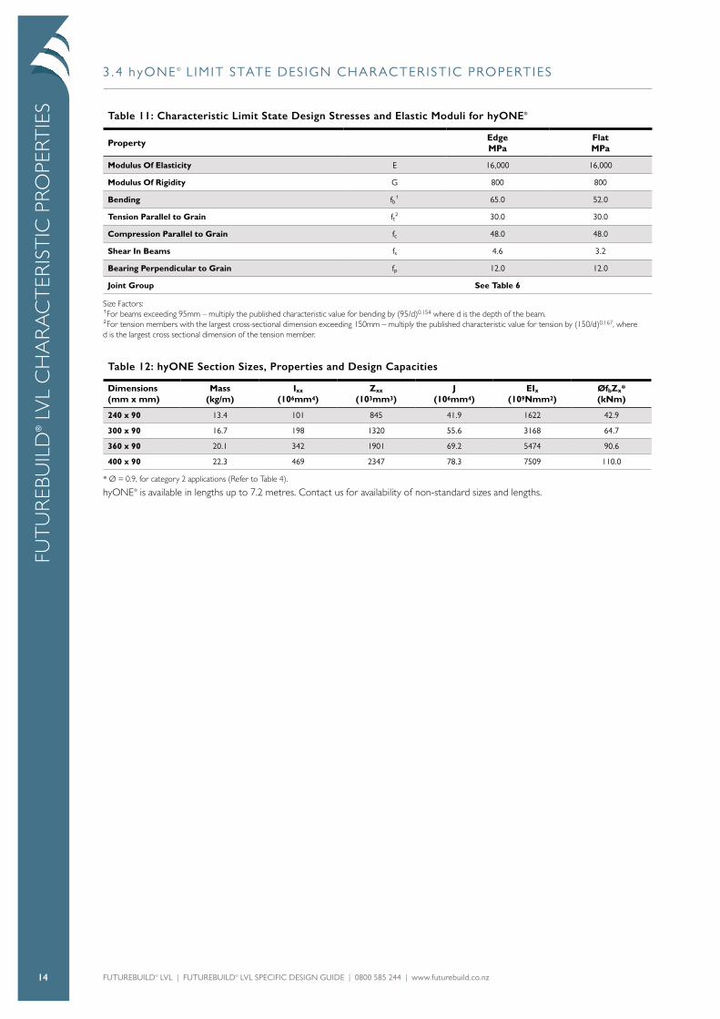
S3.4 h yONE ® L IMIT STATE DESIGN CHARACTERISTIC PROPERTIES
Table 11: Characteristic Limit State Design Stresses and Elastic Moduli for hyONE®
PropertyEdgeMPa
FlatMPa
Modulus Of Elasticity E 16,000 16,000
Modulus Of Rigidity G 800 800
Bending fb1 65.0 52.0
Tension Parallel to Grain ft2 30.0 30.0
Compression Parallel to Grain fc 48.0 48.0
Shear In Beams fs 4.6 3.2
Bearing Perpendicular to Grain fp 12.0 12.0
Joint Group See Table 6
Size Factors:1For beams exceeding 95mm – multiply the published characteristic value for bending by (95/d)0.154 where d is the depth of the beam.2For tension members with the largest cross-sectional dimension exceeding 150mm – multiply the published characteristic value for tension by (150/d)0.167, where d is the largest cross sectional dimension of the tension member.
Table 12: hyONE Section Sizes, Properties and Design Capacities
Dimensions (mm x mm)
Mass (kg/m)
Ixx (106mm4)
Zxx (103mm3)
J (106mm4)
EIx (109Nmm2)
ØfbZx* (kNm)
240 x 90 13.4 101 845 41.9 1622 42.9
300 x 90 16.7 198 1320 55.6 3168 64.7
360 x 90 20.1 342 1901 69.2 5474 90.6
400 x 90 22.3 469 2347 78.3 7509 110.0
* Ø = 0.9, for category 2 applications (Refer to Table 4).
hyONE® is available in lengths up to 7.2 metres. Contact us for availability of non-standard sizes and lengths.

FUTUREBUILD® LVL | FUTUREBUILD® LVL SPECIFIC DESIGN GUIDE | 0800 585 244 | www.futurebuild.co.nz 15
FUT
UR
EBUILD
® LVL C
HA
RA
CT
ERIST
IC PRO
PERTIES
3.5 h yCHORD ® L IMIT STATE DESIGN CHARACTERISTIC PROPERTIES
Table 13: Characteristic Limit State Design Stresses and Elastic Moduli for hyCHORD®
PropertyEdgeMPa
FlatMPa
Modulus Of Elasticity E 11,000 11,000
Modulus Of Rigidity G 550 550
Bending fb1 40.0 40.0
Tension Parallel to Grain ft2 25.2 25.2
Compression Parallel to Grain fc 32.6 32.6
Shear In Beams fs 4.4 2.5
Bearing Perpendicular to Grain fp 11.1 11.1
Joint Group See Table 6
Size Factors:1For beams exceeding 95mm – multiply the published characteristic value for bending by (95/d)0.154 where d is the depth of the beam.2For tension members with the largest cross-sectional dimension exceeding 150mm – multiply the published characteristic value for tension by (150/d)0.167, where d is the largest cross sectional dimension of the tension member.
Table 14: hyCHORD Section Sizes, Properties and Design Capacities
Dimensions (mm x mm)
Mass (kg/m)
Ixx (106mm4)
Zxx (103mm3)
J (106mm4)
EIx (109Nmm2)
ØfbZx* (kNm)
90 x 45 2.4 2.73 60.8 1.9 30.1 2.2
140 x 45 3.8 10.3 147 3.4 113 5.0
190 x 45 5.1 25.7 271 4.9 283 8.8
* Ø = 0.9, for category 2 applications (Refer to Table 4).
hyCHORD® is available in lengths up to 7.2 metres. Contact us for availability of non-standard sizes and lengths.
FUTUREBUILD® LVL | FUTUREBUILD® LVL SPECIFIC DESIGN GUIDE | 0800 585 244 | www.futurebuild.co.nz16
FUT
UR
EBU
ILD
® L
VL
CH
AR
AC
TER
IST
IC P
ROPE
RTIE
S3.6 h y JOIST ® SECTION GEOMETRY
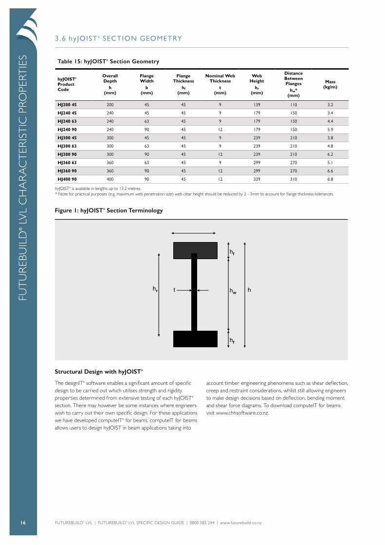
Table 15: hyJOIST® Section Geometry
hyJOIST® Product Code
Overall Depth
h (mm)
Flange Width
b (mm)
Flange Thickness
hf (mm)
Nominal Web Thickness
t (mm)
Web Height
hr (mm)
Distance Between Flanges
hw* (mm)
Mass (kg/m)
HJ200 45 200 45 45 9 139 110 3.2
HJ240 45 240 45 45 9 179 150 3.4
HJ240 63 240 63 45 9 179 150 4.4
HJ240 90 240 90 45 12 179 150 5.9
HJ300 45 300 45 45 9 239 210 3.8
HJ300 63 300 63 45 9 239 210 4.8
HJ300 90 300 90 45 12 239 210 6.2
HJ360 63 360 63 45 9 299 270 5.1
HJ360 90 360 90 45 12 299 270 6.6
HJ400 90 400 90 45 12 339 310 6.8
hyJOIST® is available in lengths up to 13.2 metres.* Note for practical purposes (e.g. maximum web penetration size) web clear height should be reduced by 2 - 3mm to account for flange thickness tolerances.
Figure 1: hyJOIST® Section Terminology
Structural Design with hyJOIST®
The designIT® software enables a significant amount of specific design to be carried out which utilises strength and rigidity properties determined from extensive testing of each hyJOIST® section. There may however be some instances where engineers wish to carry out their own specific design. For these applications we have developed computeIT® for beams. computeIT for beams allows users to design hyJOIST in beam applications taking into
account timber engineering phenomena such as shear deflection, creep and restraint considerations, whilst still allowing engineers to make design decisions based on deflection, bending moment and shear force diagrams. To download computeIT for beams visit www.chhsoftware.co.nz.

FUTUREBUILD® LVL | FUTUREBUILD® LVL SPECIFIC DESIGN GUIDE | 0800 585 244 | www.futurebuild.co.nz 17
FUT
UR
EBUILD
® LVL R
EFEREN
CES
4.0 REFERENCES
• New Zealand Building Code.• AS/NZS 4357.0:2005 Structural laminated veneer lumber – Specifications.• AS/NZS 4357.1:2005 Structural laminated veneer lumber – Methods of test for manufacturer of dimensions and shape.• AS/NZS 4357.2:2006 Structural laminated veneer lumber – Determination of structural properties – Test methods.• AS/NZS 4357.3:2006 Structural laminated veneer lumber – Determination of structural properties – Evaluation methods.• AS/NZS 4357.4:2005 Structural laminated veneer lumber – Determination of formaldehyde emissions.• NZS 3603:1993 Timber Structures Standards.• AS 1720.1-2010 Timber structures – Design methods.• AS/NZS 4063.2:2010 Characterisation of structural timber – Determination of characteristic values.• AS 1649-2001 Timber – Methods of test for mechanical fasteners and connectors – Basic working loads and characteristic strengths.
5.0 LIMITATIONS
The information contained in this document is current as at August 2019 and is based on data available to Futurebuild® LVL at the time of going to print.
All photographic images are intended to provide a general impression only and should not be relied upon as an accurate example of Futurebuild LVL products installed in accordance with this document or NZ Building Code compliance documents.
This publication replaces all previous Futurebuild LVL design information and literature relating to Futurebuild LVL products. Futurebuild LVL reserves the right to change the information contained in this document without prior notice. It is your
responsibility to ensure that you have the most up to date information available, including at the time of applying for a building consent. You can call toll free on 0800 585 244 or visit www.futurebuild.co.nz to obtain current information.
Futurebuild® LVL has used all reasonable endeavours to ensure the accuracy and reliability of the information contained in this document. However, to the maximum extent permitted by law, Futurebuild LVL assumes no responsibility or liability for any inaccuracies, omissions or errors in this information nor for any actions taken in reliance on this information.

FUTUREBUILD® LVL | FUTUREBUILD® LVL SPECIFIC DESIGN GUIDE | 0800 585 244 | www.futurebuild.co.nz18
FUTUREBUILD® LVL | FUTUREBUILD® LVL SPECIFIC DESIGN GUIDE | 0800 585 244 | www.futurebuild.co.nz 19

Private Bag 92108Victoria Street WestAuckland 1142New Zealand
Freephone: 0800 585 244
www.futurebuild.co.nzwww.chhsoftware.co.nz
© August 2019