fuzzy analogical gates approach for heat integrated ... 133 – no.2, january 2016 24 fuzzy...
TRANSCRIPT

International Journal of Computer Applications (0975 – 8887)
Volume 133 – No.2, January 2016
24
Fuzzy Analogical Gates Approach for Heat Integrated
Distillation Systems
M. H. Hussein
Assistant Professor Chemical & Petroleum Refining Engineering
High Institute of Engineering Shorouk Academy
Heba A. A. Gawad Senior Teaching Assistant
Chemical & Petroleum Refining Engineering High Institute of Engineering
Shorouk Academy
ABSTRACT
In this paper a new systematic method for optimal synthesis of
heat integrated distillation column has been developed, the
proposed method which is fuzzy analogical gates consists of
three sequential steps to select the best separation sequence:
estimation of the normalized variables parameters, Fuzzy
analogical gates and selection of the best split, Two analogical
gates (symmetric and asymmetric) are employed. The
symmetric gate (AND gate) inputs are the normalized heat
load, normalized column temperature difference. The
asymmetric gate (Invoke gate) inputs are the output of the
AND gate and the normalized (Q.∆T). The method has been
tested for three problems reported in the literature which have
been solved previously using other approaches.
Keywords
Heat Integration, Fuzzy Analogical Gates, Energy saving,
Distillation columns, Heat Recovery, Process Synthesis.
1. INTRODUCTION In the chemical industries, the task of separation is a very
energy consuming process, where distillation is the process
most widely used for fluid separations. With rising energy
awareness and growing environmental concerns there is a
need to reduce the energy use in industry. Distillation systems
consume large amounts of energy to achieve separation. In
view of increasing energy costs, it is important to design
distillation systems which consume less energy. Several
authors have described intuitive schemes minimizing energy
consumption in multicomponent distillation processes, for
example, King [1], Petlyuk et al. [2], Stupin and Lockhart [3].
In a recent paper, Rathore et al. [4] described a strategy for
synthesizing optimal separation systems with energy
integration. The major drawback of this strategy is that it does
not allow pressure variations in the separation subproblems to achieve energy integration. It is found that many more energy
matches become possible when pressure variation is allowed.
More specifically, for distillation systems, pressure is an
important operating and design parameter that determines
both the ease of separation and the level of energy integration.
An energy savings should have an impact on the overall plant
energy consumption. A drastic reduction in heating demand in
a distillation train can be achieved by upgrading the heat flow
recovered from condensers and using it to meet process
energy requirements. Several synthesis techniques have been
published for finding the separation strategy, the column
pressures and the heat exchanger network structure that
minimize utility needs in a distillation train. These generally
use two approaches, namely thermodynamic and algorithmic
methods. In addition, several rules of thumb for making a
quick selection of a good separation strategy have been
known for years Rudd & Powers [6]
The use of heat integration combined with complex
configurations for distillation columns holds a great promise
of energy savings up to about 70%. In addition to saving
energy, accompanied by reduced environmental impact and
site utility costs, there is also a possibility for reduction in
capital costs. The classical design of a multicomponent
distillation plant only involves simple columns: each simple
column in a multicomponent distillation configuration
receives a feed and performs a sharp separation between two
components of the feed mixture.
The calculation of the heat integration cost depend on using
the hot product as heating medium (instead of regular
reboiler) from one of the column in heating the bottom of
another column (instead of regular condenser). In this case
there is no cooling system and the cooled stream return as
reflux to the main column from which it was taken, in this
case there is no need for the condenser and there is no
superheated steam for the reboiler.
In this paper a new method for optimal synthesis of heat
integrated distillation column has been presented, the
proposed method consists of three sequential steps to select
the best separation sequence, the results of case studies show
that Fuzzy analogical gates strategy is both robust and
accurate in decision making while there are large possibilities
in separation sequence and it‟s hard to decide which one is the
optimum. in comparison with previous works, which ensures
its economic effectiveness.
2. PROBLEM STATEMENT This study is restricted to separation by ordinary distillation.
Every distillation column represents an energy sink (reboiler)
and energy source (condenser). If sinks and sources in a
sequence are combined appropriately, a significant energy
savings can be achieved. It is refer to this combination as
energy integration or column matching.
The following problem is the subject of this study: „„Given a
single Multi-component feed stream of known conditions, (i.e.
flow rate, composition, temperature and pressure), which is to
be separated into pure components”, find the sequence of
distillation column, the energy integration, the design
specifications and the operating conditions which minimize
the total cost.
To reduce the complexity of the synthesis algorithm and
simplify the solution space for the synthesis procedure, in this
study the following assumptions are made Rathore et al. [5]:

International Journal of Computer Applications (0975 – 8887)
Volume 133 – No.2, January 2016
25
1. Each distillation column performs a simple split (i.e.
one feed and two products):
2. Energy matches occur only between boiling and
condensing streams.
3. The energy match is considered between the
reboiling stream (energy sink) and the condensing
stream (energy source). Minimum approach
temperature (ΔT min) is held constant at 2.5K.
4. Each column operates at high recovery.
5. The volatility order does not change with changes in
pressure.
6. The cost of changing the temperature and pressure
of streams as they pass between columns is
negligible compared to column capital and energy
costs.
7. No matches occur with streams outside of the
distillation system.
8. No vapor recompression is used.
3. RULES OF THUMB AND HEURISTIC
ALGORITHM From analyzing the profit of heat integration Meszaros and
Fonyo, [7], it can be observed that the column temperature
difference and column heat load have an outstanding effect on
profitability. Considering these properties the following rules
of thumb can be formulated:
Rule1: Favour heat matches of additional heating
requirement. Those matches should be preferred where the
heat load of the source column (which boils the sink column)
is less than the heat load of the sink column.
Rule2: Avoid the use of high-temperature utility. In order to
avoid the application of an unusually high temperature utility
required by a high-pressure source column it is expedient to
strive for a distillation system with a more even temperature
profile.
Rule3: Favour matches with maximum heat exchange.
Respecting rule 1 the match with a better connection is more
advantageous: when several columns can be considered as a
candidate for heating a sink column, the match demanding the
least additional heating of the sink column is selected.
4. FUZZY ANALOGICAL GATES
STRATEGY Based on the strategy of Fuzzy analogical gate S.Aly [8] the
following algorithm was developed to select a small number
of nearly optimal heat-integrated distillation structures and it
consists of four steps:
Step1 Reject candidate matches for heat integration where the
heat load of the source column is larger than that of the sink
column.
Step2 Do not match the columns with the greatest
temperature differences; select the match or matches with the
largest heat load for the source column (s). When several
schemes with the same value of the source column heat load
are available and only one match is involved, prefer the
column with the smallest temperature difference as the heat
sink. When the schemes include distinct paired columns,
prefer the scheme involving the lowest value of the highest
total match temperature difference.
Step3 Repeat step 2 for the remaining candidate schemes.
Step4 Fuzzy analogical gates strategy
Fig.1. Fuzzy Analogical Gates Strategy
The algorithm which is followed in this step is to select the
best separation sequence which consists of three sequential
steps: estimation of the normalized variables parameters,
Fuzzy analogical gates and selection of the best split, as
shown in Fig. 1. Most of the previous work shows that the
synthesis of separation mostly depends on the heat load,
column temperature difference, and (Q.ΔT). Accordingly, in
this work these three variables have been selected as inputs to
the different fuzzy analogical gates.
4.1.Fuzzy Analogical Gates Network Two fuzzy analogical gates will be used sequentially as
shown in Fig.2 Hussein [9]. The first gate is selected to be
symmetric and the second gate is asymmetric. A fuzzy
analogical - AND gate will be followed by a fuzzy invoke
gate.
Fig.2. Fuzzy Analogical Gates Network
As shown in Fig. 2, which is analogical gates network consists
of two analogical gates (symmetric and asymmetric). The
symmetric gate inputs are the normalized heat load (Q) and
the normalized temperature difference (ΔT). The asymmetric
gate inputs are the output of the symmetric gate and (Q. ΔT).
for each value of [Q, ΔT and Q.ΔT] can be derived by
application of a linear programming code, two bounds (ƒ) min
& (ƒ) max can be computed, and the normalized variables can
be estimated by
maxmin
max
ff
ff
, Where (1)
0 If maxff ; 1 If minff
4.2. Choice of the Best Separation
Weight The final step corresponds to the choice of the best separation
weight. The operation is carried out by comparing (S.W)
values for all minimum approach temperature and by
choosing the greatest one.
Fuzzy analogical gates network
Normalized variables parameters
[Q], [ΔT], [Q.ΔT]
Choice of the best weight index
For each
split of the
separation
ΔT Q. ΔT
atility
AND Invoke Separation
Weight Q

International Journal of Computer Applications (0975 – 8887)
Volume 133 – No.2, January 2016
26
S.W optimum = max {S.W1, S.W2, S.W 3 ……} (2)
5. EXAMPLES The proposed method will be tested using three case studies
reported in the literature, for comparison.
5.1. Example 1: Separation of a 5
component mixture This example was discussed first by Heaven [10], then (Perry
and Chilton, [11]; Rathore et al., [4 and 5]; Freshwater and
Ziogou [12]. The feed stream is 907.2 by mol/hr, composed of
five light hydrocarbons shown in Table 1; to be separated into
essentially pure components (98% recovery for both keys in
all columns). The best sequence without heat integration is
[A/BCDE, BC/DE, B/C, D/E] according to Heaven (1969).
Stream data are given in Table 1, the optimal parameters of
distillation columns according to Rathore et al. [4 and 5],
Morari and Faith [13] are shown in Table 2. All feasible
matches for the sequences [A/BCDE, BC/DE, B/C, D/E] are
summarized in the Matrix Integration in Table 3. Fuzzy
analogical gates inputs and Fuzzy Analogical gates results are
shown in Table 4 and 5. Figure 3 shows the final flow sheet of
the integrated system with two columns
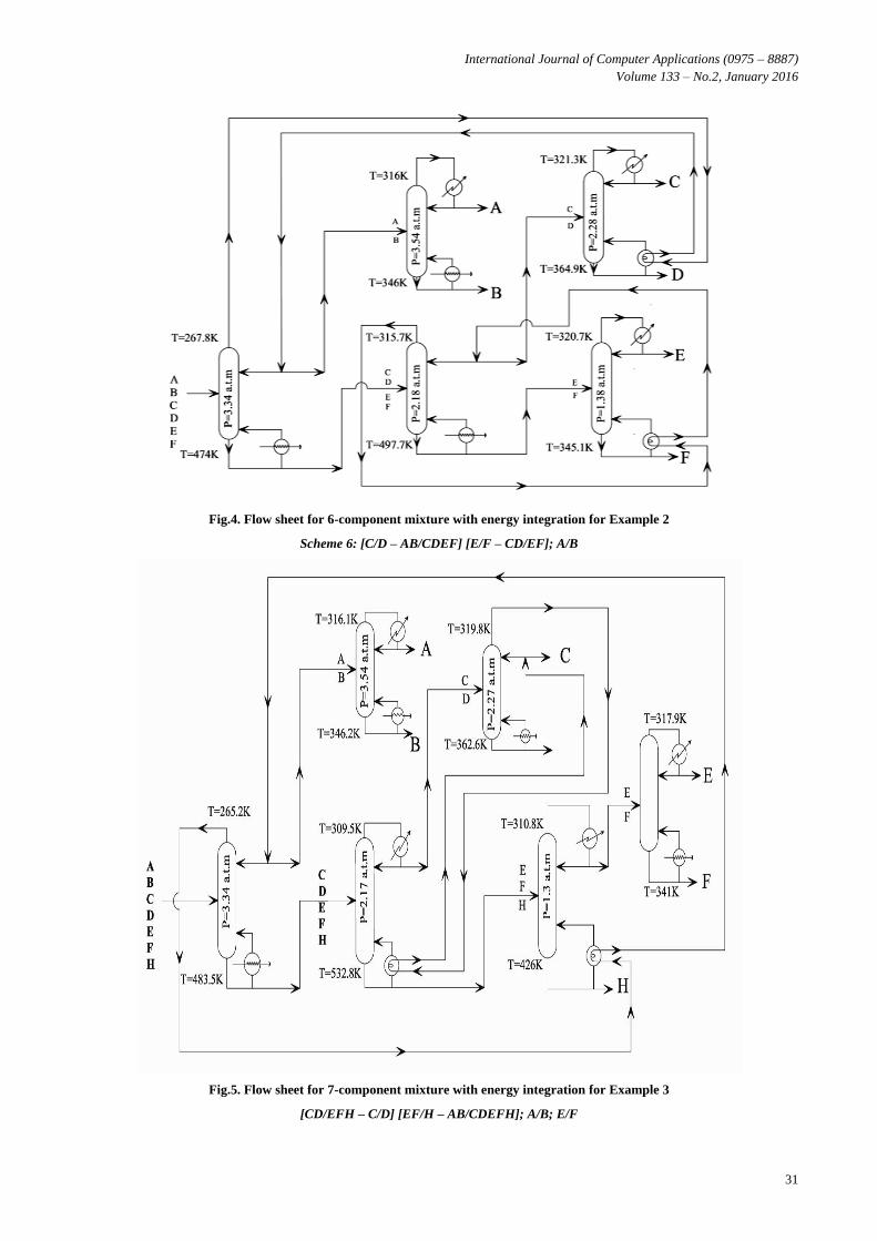
5.2. Example 2: Separation of a 6
component mixture This example consists of six component feed stream that has
to be separated into six-component products by sharp
separators; Table 7 reports the main data for the feed flow
rate; Towers cost are given in Table 8 Hussein [14], The
characteristics of separation subproblems for the mixture
[ABCDEF] are given in Table 9.
The best sequence without heat integration is [AB/CDEF,
CD/EF, A/B, C/D, E/F] with total annual cost of US$
2,507,833.23. All feasible matches are summarized in the
matrix Integration in Table 10. Fuzzy analogical gates inputs
and results are shown in Table 11 and 12. The total annual
cost with heat integration is equal to US$ 2,163,833 which
gives 13.72 % reduction in cost compared with separation
sequence without heat integration. Figure 4 shows the final
flow sheet of the integrated system with four columns.
5.3. Example 3: Separation of a 7
component mixture This example consists of seven component feed stream with
feed flowrate of 1600 Kmol/ hr that has to be separated into
seven component products by sharp separators; Table 13,
reports the main data for the feed flow rate. The
characteristics of separation subproblems for the mixture
[ABCDEFH] are given in Table 14. The best sequence
without heat integration is [AB/CDEFH, CD/EFH, A/B, C/D,
EF/H, E/F], with total annual cost of US$ 6,589,980.56. All
feasible matches are summarized in the matrix Integration in
Table 15. Fuzzy analogical gates inputs and results are shown
in Table 16 and 17. The total annual cost with heat integration
is equal to US$ 5,981,725.35, which gives 9.23 % reduction
in cost compared with the separation sequence without heat
integration. Figure 5 shows the final flow sheet of the
integrated system with four columns.
Table 1: Stream data for Example 1
Component Flowrate (mol/h)
A: Propane 45.4
B: Iso-Butane 136.1
C: N-Butane 226.8
D: Iso-Pentane 181.4
E: N-Pentane 317.5
Table 2: Optimal parameters of distillation columns in
example according to Morari and Faith (1980) and
Rathore et al., (1974)
Column Heat Load
(MMkcal/hr)
Column temp.
difference (K)
Total
annual cost
($/yr)
A/BCDE 6.490 64.72 36,490
BC/DE 18.88 44.75 77,570
B/C 23.90 12.72 83,400
D/E 49.27 11.52 156,800
Table 3: Matrix Integration for Example 1
Sink column
Source column A/BCDE BC/DE D/E B/C
A/BCDE R2
BC/DE R1
D/E R1 R1 R1
B/C R1 R1
Step1. All feasible matches for the separation train
[A/BCDE, BC/DE, B/C, D/E] which provides the best heat-
integrated scheme according to Morrari [13] are summarized
in table 2. The matches indicated by R1 are rejected because
of rule 1.
Step2. The match of columns A/BCDE and BC/DE is
indicated by R2 is rejected because of their great temperature
difference. From the first two steps 60% of the feasible
matches could be rejected.
From the matrix of heat integration, we have the following
schemes:
Scheme 1: [D/E – A/BCDE] [B/C – BC/DE];
Scheme 2: [D/E – BC/DE] [B/C – A/BCDE];
Scheme 3: [D/E – B/C]; A/BCDE, BC/DE.
Fuzzy analogical gates inputs parameters (Q, ΔT and Q. ΔT)
for different schemes are given in Table 4.
Step3. Two separation scheme provide the largest heat load of
the source column with 25.37 Kcal/hr, [D/E – A/BCDE] [B/C
– BC/DE] and [D/E – BC/DE] [B/C – A/BCDE].The former
scheme includes total match temperature differences 76.24
and 57.47 K, while the latter scheme contains differences of
77.44 and 56.27 K as shown in Table 4. Since from the
highest values of the total temperature difference in the
schemes (76.24 and 77.44K), the match [D/E – A/BCDE]
with 76.24 has the lowest value, the former (scheme 1) is
preferred.

International Journal of Computer Applications (0975 – 8887)
Volume 133 – No.2, January 2016
27
Table 4: Fuzzy analogical gates inputs for Example 1
Distillation
schemes
Q x106
(kcal/hr)
ΔT
(K)
Q. ΔT x 106
(Kcal K/hr)
Scheme 1 25.37 [76.24, 57.47] [987.6, 1148.8]
Scheme 2 25.37 [56.27, 77.44] [1412, 724.04]
Scheme 3 23.90 [12.72] [871.59]
Step4. The scheme with the next largest heat load of the
source column is [D/E – B/C]; A/BCDE, BC/DE including a
23.90 Kcal/hr heat load.
The output of the analogical invoke gate is the separation weight
and by comparing the results for all possible schemes. Scheme 1
is selected thus; yields the greatest value (1.00). The same
procedure is then applied for the other schemes.
The Fuzzy Analogical gates results of the proposed method is
shown in Table 5, thus the resulting sequence is
Scheme 1: [D/E – A/BCDE] [B/C – BC/DE]
Table 5: Fuzzy Analogical gates results for Example 1
schemes µ1 µ2 µ3 S.W
1 1.000 0.984 1.000 1.000
2 1.000 1.000 0.733 0.997
3 0.942 0.164 0.882 0.037
A comparison for different approach according to Morari and
Faith [13], Meszaros and Fonyo [8] and the proposed method
is shown in Table 6.
Table 6: Best heat integrated structures for the separation
sequence [A/BCDE, BC/DE, B/C, D/E] with two columns
matches in example for different approach
Morari and
Faith
[13]
Meszaros
and Fonyo
[8]
Fuzzy
Analogical
Gates
Scheme TAC ($/yr) ΔT S.W
Scheme 1 312,250 76.24 1.000
Scheme 2 312,480 77.44 0.997
Scheme 3 - - 0.037
Table 7: Stream data for Example 2
Component Flowrate
(kmol/h)
Boiling point
temperature
(K)
Relative
Volatility
(α)
A: Propylene 96.0 225.4
1.208
B: Propane 96.0 231.1
2.351
C: Iso-Butane 383.3 261.3
1.067
D: N-Butane 192.7 272.7
3.000
E: Iso-Pentane 239.1 300.8
1.037
F: N-Pentane 192.9 309.0
Table 8: Towers Cost of Example 2
Column Total annual cost
($/yr)
AB/CDEF 482,000
CD/EF 558,000
A/B 344,000
C/D 489,000
E/F 634,000
Table 9: Characteristics of separation Example 2
Colu
mn
Top
tem
p.
(K)
Bott
om
tem
p.
(K)
Pres
sure
(atm
.)
Con
den
se
du
ty x
10
6
(Kcal/
hr)
Reb
oil
er
du
ty
x 1
06 (
Kca
l/h
r)
ΔT
(K
)
AB/CDEF 267.8 474.0 3.34 2.50 4.73 206.2
CD/EF 315.7 497.7 2.18 6.10 10.1 182.0
A/B 316.0 346.0 3.54 4.81 5.32 30
C/D 321.3 364.9 2.28 9.87 11.3 43.6
E/F 320.7 345.1 1.38 11.1 12.1 24.4
Table 10: Matrix Integration Example 2
Sink column
Sou
rce
colu
mn
AB
/CD
EF
CD
/EF
A/B
C/D
E/F
AB/CDEF R2
CD/EF R1 R1
A/B R1
C/D R1 R1 R1
E/F R1 R1 R1 R1
From the matrix of heat integration, we have the following
schemes:
Scheme 1: [CD/EF - A/B] [C/D – AB/CDEF];
E/F
Scheme 2: [CD/EF - A/B] [E/F – AB/CDEF];
C/D
Scheme 3: [A/B – AB/CDEF] [C/D – CD/EF];
E/F
Scheme 4: [A/B – AB/CDEF] [E/F – CD/EF];
C/D
Scheme 5: [A/B – AB/CDEF] [E/F – C/D];
CD/EF
Scheme 6: [C/D – AB/CDEF] [E/F – CD/EF];
A/B
Scheme 7: [C/D – AB/CDEF] [E/F – A/B];
CD/EF
Scheme 8: [C/D –CD/EF] [E/F – AB/CDEF];
A/B
Scheme 9: [C/D – CD/EF] [E/F – A/B];
AB/CDEF

International Journal of Computer Applications (0975 – 8887)
Volume 133 – No.2, January 2016
28
Scheme 10: [C/D – A/B] [E/F – AB/CDEF];
CD/EF
Scheme 11: [C/D –A/B] [E/F – CD/EF];
AB/CDEF
Scheme 12: [E/F – C/D] [CD/EF – A/B];
AB/CDEF
The results of Fuzzy analogical gates inputs parameters (Q,
ΔT and Q. ΔT) for different schemes are given in Table 11.
Table 11: Fuzzy analogical gates inputs for Example 2
Distillation
schemes
Q x106
(kcal/hr) ΔT (K)
Q. ΔT x 106
(Kcal K/hr)
1 10.05 [212, 249.8] [1997.8, 1468.1]
2 10.05 [212, 230.6] [1997.8, 1270.5]
3 14.83 [236.2,225.6] [1134.9, 2330.8]
4 14.83 [236.2,206.4] [1134.9, 2133.4]
5 16.03 [236.2, 68] [1134.9, 787.9]
6 14.83 [249.8,206.4] [1468.1, 2133.4]
7 10.05 [249.8, 54.4] [1468.1, 454.8]
8 14.83 [225.6,230.6] [2133.4, 1270.5]
9 15.42 [225.6, 54.4] [2133.4, 454.8]
10 10.05 [73.6, 230.6] [652.2, 1270.5]
11 15.42 [73.6, 206.4] [652.2, 2133.4]
12 16.62 [68, 212] [787.9, 1997.8]
The Fuzzy Analogical gates results is shown in Table 12, thus
the resulting sequence is
Scheme 6: [C/D – AB/CDEF] [E/F – CD/EF]; A/B
Table 12: Fuzzy Analogical gates results for Example 2
schemes µ1 µ2 µ3 S.W
1 0.604 1.000 1.000 0.714
2 0.604 0.923 0.865 0.718
3 0.892 0.945 0.773 0.937
4 0.892 0.945 0.773 0.937
5 0.964 0.945 0.536 0.920
6 0.892 1.000 1.000 1.000
7 0.604 1.000 0.309 0.600
8 0.892 0.923 0.865 0.952
9 0.927 0.903 0.309 0.875
10 0.604 0.923 0.444 0.633
11 0.927 0.826 0.444 0.829
12 1.000 0.848 0.536 0.872
Table 13: Stream data for Example 3
component Mole
fraction
Boiling point
temperature
(K)
Relative
Volatility
(α) A:Propylene 0.060 225.4
1.236
B: Propane 0.060 231.1
1.021
C:Iso-Butane 0.240 261.3
1.529
D:N-Butane 0.156 272.7
2.400
E:Iso -Pentane 0.120 300.8
1.520
F: N-Pentane 0.250 309.0
4.152
H: N-Hexane 0.120 341.7
The characteristics of separation subproblems for the mixture
[ABCDEFH] are given in Table 14
Table 14: Characteristics of separation for Example 3
Colu
mn
Top
tem
p.
(K)
Bott
om
tem
p.
(K)
Pres
sure
(atm
.)
Con
den
ser
du
ty x
10
6
(Kcal/
hr)
Reb
oil
er
du
ty
x 1
06 (
Kca
l/h
r)
ΔT
(K
)
AB/CDEFH 265.2 483.5 3.34 2.53 4.97 218.3
CD/EFH 309.5 532.8 2.17 6.21 11.4 223.3
EF/H 310.8 426 1.30 5.01 7.13 115.2
A/B 316.1 346.2 3.54 4.50 4.99 30.1
C/D 319.8 362.6 2.27 9.76 11.2 42.8
E/F 317.9 341 1.36 10.2 11.09 23.1
All feasible matches for the sequences [AB/CDEF, CD/EF,
A/B, C/D, E/F] are summarized in the matrix integration
shown in Table 15
Table 15: Matrix Integration for Example 3
Sink column
Sou
rce
colu
mn
AB
/CD
EF
H
CD
/EF
H
EF
/H
A/B
C/D
E/F
AB/CDEF
H
R2
CD/EFH R1 R1 R1 R1 R1
EF/H R1 R1
A/B R1
C/D R1 R1 R1 R1
E/F R1 R1 R1
From the matrix of heat integration, we have the
following schemes:
Scheme 1: [CD/EFH – EF/H] [A/B – AB/CDEFH]; C/D; E/F
Scheme 2: [CD/EFH – EF/H] [C/D – AB/CDEFH]; A/B; E/F
Scheme 3: [CD/EFH – EF/H] [C/D – A/B]; AB/CDEFH; E/F
Scheme 4: [CD/EFH – EF/H] [C/D – E/F]; AB/CDEFH; A/B
Scheme 5: [CD/EFH – EF/H] [E/F – AB/CDEFH]; A/B; C/D
Scheme 6: [CD/EFH – EF/H] [E/F – A/B]; AB/CDEFH; C/D
Scheme 7: [CD/EFH – A/B] [EF/H – AB/CDEFH]; E/F; C/D
Scheme 8: [CD/EFH – A/B] [C/D – EF/H]; AB/CDEFH; E/F
Scheme 9: [CD/EFH – A/B] [C/D – E/F]; AB/CDEFH; EF/H
Scheme 10: [CD/EFH – C/D] [EF/H – AB/CDEFH]; A/B; E/F
Scheme 11: [CD/EFH – C/D] [EF/H – A/B]; AB/CDEFH; E/F
Scheme 12: [CD/EFH – E/F] [EF/H –AB/CDEFH]; C/D; A/B

International Journal of Computer Applications (0975 – 8887)
Volume 133 – No.2, January 2016
29
Scheme 13: [CD/EFH – E/F] [EF/H – A/B]; AB/CDEFH; C/D
Scheme 14: [CD/EFH – E/F] [C/D – EF/H]; AB/CDEFH; A/B
Scheme 15: [A/B – AB/CDEFH] [CD/EFH – C/D]; EF/H; E/F
Scheme 16: [A/B – AB/CDEFH] [CD/EFH – E/F]; EF/H; C/D
Scheme 17: [C/D – AB/CDEFH] [CD/EFH – A/B]; EF/H; E/F
Scheme 18: [C/D – AB/CDEFH] [EF/H – A/B]; CD/EFH; E/F
Scheme 19: [C/D – AB/CDEFH] [E/F – EF/H]; CD/EFH; A/B
Scheme 20: [C/D – AB/CDEFH] [E/F – A/B]; CD/EFH; EF/H
Scheme 21: [C/D – EF/H] [A/B –AB/CDEFH]; CD/EFH; E/F
Scheme 22: [C/D – A/B] [CD/EFH – E/F]; AB/CDEFH; EF/H
Scheme 23: [C/D – A/B] [EF/H – AB/CDEFH]; CD/EFH; E/F
Scheme 24: [C/D – A/B] [E/F – AB/CDEFH]; CD/EFH; EF/H
Scheme 25: [C/D – A/B] [E/F – EF/H]; AB/CDEFH; CD/EFH
Scheme 26: [C/D – E/F] [EF/H – AB/CDEFH]; CD/EFH; A/B
Scheme 27: [C/D – E/F] [EF/H – A/B]; AB/CDEFH; CD/EFH
Scheme 28: [C/D – E/F] [A/B –AB/CDEFH]; CD/EFH; EF/H
Scheme 29: [E/F – AB/CDEFH] [CD/EFH – A/B]; C/D; EF/H
Scheme 30: [E/F – AB/CDEFH] [CD/EFH – C/D]; EF/H; A/B
Scheme 31: [E/F – AB/CDEFH] [EF/H – A/B]; CD/EFH; C/D
Scheme 32: [E/F – AB/CDEFH] [C/D – EF/H]; CD/EFH; A/B
Scheme 33: [E/F – EF/H] [CD/EFH – A/B]; AB/CDEFH; C/D
Scheme 34: [E/F – EF/H] [CD/EFH – C/D]; AB/CDEFH; A/B
Scheme 35: [E/F – EF/H] [A/B – AB/CDEFH]; CD/EFH; C/D
Scheme 36: [E/F – A/B] [CD/EFH – C/D]; AB/CDEFH; EF/H
Scheme 37: [E/F – A/B] [EF/H – AB/CDEFH]; C/D; CD/EFH
Scheme 38: [E/F – A/B] [C/D – EF/H]; AB/CDEFH; CD/EFH
The results of Fuzzy analogical gates inputs parameters (Q,
ΔT and Q. ΔT) for different schemes are given in Table 16.
Table 16: Fuzzy analogical gates inputs for Example 3
Scheme Q x10
6
(kcal/hr) ΔT (K)
Q. ΔT x 106
(Kcal K/hr)
1 12.10 [338.5, 248.4] [3366.9, 1235.1]
2 12.10 [338.5, 261.1] [3366.9,1564.3 ]
3 12.12 [338.5, 72.9] [3366.9, 629.5]
4 18.22 [338.5, 65.9] [3366.9, 735.5]
5 12.10 [338.5, 241.4] [3366.9, 1341.1]
6 12.12 [338.5, 53.2] [3366.9, 406.3]
7 9.960 [253.4, 333.5] [2695.8, 1906.3]
8 12.12 [253.4, 158] [2695.8, 1300.7]
9 16.08 [253.4, 65.9] [2695.8, 735.5]
10 16.17 [266.1, 333.5] [3024.9, 1906.3]
11 16.19 [266.1, 145.3] [3024.9, 971.5]
12 16.06 [246.4, 333.5] [2801.7, 1906.3]
13 16.08 [246.4, 145.3] [2801.7, 971.5]
14 18.22 [246.4, 158] [2801.7, 1300.7]
Scheme Q x10
6
(kcal/hr) ΔT (K)
Q. ΔT x 106
(Kcal K/hr)
15 16.17 [248.4, 266.1] [1235.1, 3024.9]
16 16.06 [248.4, 246.4] [1235.1, 2801.7]
17 9.960 [261.1, 253.4] [1564.3, 2695.8]
18 9.960 [261.1, 145.3] [1564.3, 971.5]
19 12.10 [261.1, 138.3] [1564.3, 1077.5]
20 9.960 [261.1, 53.2] [1564.3, 406.3]
21 12.10 [158, 248.4] [1300.7, 1235.1]
22 16.08 [72.9, 246.4] [629.5, 2801.7]
23 9.960 [72.9, 333.5] [629.5, 1906.3]
24 9.960 [72.9, 241.4] [629.5, 1341.1]
25 12.12 [72.9, 138.3] [629.5, 1077.5]
26 16.06 [65.9, 333.5] [735.5, 1906.3]
27 16.08 [65.9, 145.3] [735.5, 971.5]
28 16.06 [65.9, 248.4] [735.5, 1235.1]
29 9.960 [241.4, 253.4] [1341.1, 2695.8]
30 16.17 [241.4, 266.1] [1341.1, 3024.9]
31 9.960 [241.4, 145.3] [1341.1, 971.5]
32 12.10 [241.4, 158] [1341.1, 1300.7]
33 12.12 [138.3, 253.4] [1077.5, 2695.8]
34 18.33 [138.3, 266.1] [1077.5, 971.5]
35 12.10 [138.3, 248.4] [1077.5, 1235.1]
36 16.19 [53.2, 266.1] [406.3, 971.5]
37 9.960 [53.2, 333.5] [406.3, 1906.3]
38 12.12 [53.2, 158] [406.3, 1300.7]
The Fuzzy Analogical gates results is shown in Table 17, thus
the resulting sequence is
Scheme 10:
[CD/EFH – C/D] [EF/H – AB/CDEFH]; A/B; E/F
6. CONCLUSIONS
Process integration does not only involve the search for the
optimal design parameters, but even more important the
development of the optimal processing strategy. The decision
is often based on rules of thumb or on exhaustive enumeration
of all the possibilities. Fuzzy analogical gate strategy has been
proposed for synthesizing multicomponent separation
sequences for five, six and seven components and helping for
decision making when there are a large number of
possibilities.
Table 17: Fuzzy Analogical gates results for Example 3
Sequences µ1 µ2 µ3 S.W
1 0.660 1.000 0.647 0.731
2 0.660 1.000 0.820 0.768
3 0.660 1.000 0.330 0.670
4 0.993 1.000 0.385 0.951
5 0.660 1.000 0.703 0.744
6 0.660 1.000 0.213 0.673
7 0.543 0.985 1.000 0.621
8 0.660 0.748 0.682 0.733
9 0.877 0.748 0.385 0.758
10 0.882 0.989 1.000 0.996
11 0.883 0.786 0.509 0.802
12 0.876 0.985 1.000 0.991
13 0.877 0.727 0.509 0.760
14 0.993 0.727 0.682 0.806
15 0.882 0.786 0.647 0.831

International Journal of Computer Applications (0975 – 8887)
Volume 133 – No.2, January 2016
30
Sequences µ1 µ2 µ3 S.W
16 0.876 0.733 0.647 0.795
17 0.543 0.771 0.820 0.656
18 0.543 0.771 0.509 0.600
19 0.660 0.771 0.565 0.709
20 0.543 0.771 0.213 0.556
21 0.660 0.773 0.647 0.729
22 0.877 0.727 0.330 0.738
23 0.543 0.985 0.330 0.529
24 0.543 0.713 0.330 0.563
25 0.660 0.408 0.330 0.429
26 0.876 0.989 0.385 0.876
27 0.877 0.429 0.385 0.425
28 0.876 0.733 0.385 0.746
29 0.543 0.748 0.703 0.642
30 0.882 0.786 0.703 0.845
31 0.543 0.713 0.509 0.601
32 0.660 0.713 0.682 0.724
33 0.660 0.748 0.565 0.705
34 1.000 0.786 0.509 0.819
35 0.660 0.733 0.565 0.701
36 0.883 0.786 0.213 0.795
37 0.543 0.985 0.213 0.519
38 0.660 0.466 0.213 0.476
The heat integration matrix represents all possible matches
that could occur in the system with the aid of three heuristic
rules for identifying the feasible matches between condenser
& reboiler. It show a good percent of reduction cost compared
to the total cost without heat integration, which ensures its
economic effectiveness.
The proposed method have a large applications in chemical
and petroleum refining engineering such as heat and mass
exchanger network, waste water minimization, reactor
network, yielded optimum solutions which are consistent with
different approach.
Nomenclature
S.W Separation Weight
TAC Total Annualized Cost
µ1 Normalized Q
µ2 Normalized ΔT
µ3 Normalized Q. ΔT
Fig.3. Flow sheet for 5-component mixture with energy integration for Example 1Scheme 1:
[D/E – A/BCDE] [B/C – BC/DE]
International Journal of Computer Applications (0975 – 8887)
Volume 133 – No.2, January 2016
31
Fig.4. Flow sheet for 6-component mixture with energy integration for Example 2
Scheme 6: [C/D – AB/CDEF] [E/F – CD/EF]; A/B
Fig.5. Flow sheet for 7-component mixture with energy integration for Example 3
[CD/EFH – C/D] [EF/H – AB/CDEFH]; A/B; E/F

International Journal of Computer Applications (0975 – 8887)
Volume 133 – No.2, January 2016
32
7. REFERENCES [1] King, C. J., “Separation Processes,” McGraw-Hill, New
York (1971)
[2] Petlyuk, F. B., Platonov, V. M., and D. M. Slavinskii,
“Thermodynamically optimal method for separating
multicomponent mixtures,” Int. Chem. Eng., 5, 555
(1965).
[3] Stupin, W. J., and F. J. Lockhart, “Thermally Coupled
Distillation”, Chem. Eng. Progr. 68, (10), 71 (1972).
[4] Rathore, R.N. S., K. A. Vanwormer, and G. J. Powers,
“Synthesis Strategies for Multicomponent Seqparation
Systems with Energy Integration,” AlChE J., 20, 491
(1974a).
[5] Rathore, R.N. S., K. A. Vanwormer, and G. J. Powers,
Synthesis of Distillation Systems with Energy
Integration, AlChE J. 20, 940 (1974b).
[6] Rudd & Powers, “A heuristic method for the creation of
a separation scheme”, Ind. Eng. Chem. Res., Vol. 5, 255
(1973).
[7] Meszaros I. and Z. Fonyo, Parametric studies and
extensive state optimization for energy integrated
distillation systems, Hung. J. Ind. Chem., Vol.14 pp.203
(1986),.
[8] Aly. S, Fuzzy analogical gates for separation sequence
synthesis, Chem. Eng. Proc, Vol. 36 (1997) 209-217.
[9] Hussein, M.H., Moselhy, H., Aly S., Awad, M. E.
“Fuzzy Analogical Gates Approach for Heat Exchangers
Networks”. International Journal of Computer
Applications. Vol. 73, No. (21): pp.1-8, (July 2013)
[10] Heaven D.L, “Optimum sequencing of distillation
columns in multicomponent fractionation”, M.Sc. Thesis,
University of California Berkley. (1969).
[11] Perry, R. H., and C. H. Chilton (ed.), Chemical
Engineers’ Handbook, 5th ed., McGraw Hill (1973).
[12] Freshwater, D. C., and E. Ziogou, “Reducing Energy
Requirements in Unit Operations”, Chem. Eng. J., 11,215
(1976).
[13] Morari M., and D.C. Faith, The synthesis of distillation
trains with heat integration, AIChE J. Vol. 26 (1980) 916.
[14] Hussein, M.H. “ Synthesis of optimal heat integrated
distillation systems” M.Sc Thesis, University of Suez
(2010)
IJCATM : www.ijcaonline.org