fuzzy logic – genetic algorithm based maximum power...
TRANSCRIPT

FUZZY LOGIC – GENETIC ALGORITHM BASED MAXIMUM POWER
POINT TRACKING IN PHOTOVOLTAIC SYSTEM
ZALIFAH BINTI TUKEMAN
A project report submitted in partial
fulfillment of the requirement for the award of the
Degree of Master of Electrical Engineering
Faculty of Electrical and Electronic Engineering
Universiti Tun Hussein Onn Malaysia
JULY 2012
v
ABSTRACT
This project is about to carried out the optimization and implementation a fuzzy
logic controller (FLC) used as a maximum-power-point tracker for a PV system, are
presented. Maximum power point tracking (MPPT) are used to integrate with
photovoltaic (PV) power systems so that the photovoltaic arrays are able to deliver
the maximum power available. The near optimum design membership functions and
control rules were found simultaneously by genetic algorithms (GAs) which are
search algorithms based the mechanism of natural selection and genetics. These are
easy to implement and efficient for multivariable optimization problems such as in
fuzzy controller design that consist large number. The FLC designed and the
implementation of photovoltaic model using Matlab/Simulink software package
which can representative of PV cell module. Taking effect of sunlight irradiance and
cell temperature into consideration, the output power and current characteristics of
PV model are simulated and optimized.

vi
ABSTRAK
Projek ini membentangkan cara untuk mengoptimum dan melaksanakan pengawal
logik kabur yang digunakan sebagai pengesan titik kuasa maksimum di dalam solar
panel. Pengesanan titik kuasa maksimum digunakan untuk digabungkan dengan
sistem kuasa solar supaya system kuasa solar mampu untuk menyampaikan bekalan
kuasa maksimum. Nilai optimum terdekat direka untuk fungsi keahlian dan
peraturan kawalan ditemui secara serentak oleh algoritma genetik oleh algoritma
carian berdasarkan mekanisme pemilihan semula jadi dan genetik. Cara ini mudah
untuk melaksanakan dan cekap untuk masalah pengoptimuman pembolehubah
seperti dalam rekabentuk pengawal kabur yang terdiri dengan bilangan yang besar.
FLC yang direka bentuk dan pelaksanaan model solar menggunakan perisian Matlab
/ Simulink yang mewakili model solar yang sebenar. Untuk mendapatkan keputusan
simulasi dan nilai optimum, ambil kira kesan sinaran cahaya matahari dan suhu sel
dalam pertimbangan, keluaran kuasa dan arus ciri-ciri model solar.

vii
TABLE OF CONTENTS
TITLE i
DECLARATION ii
DEDICATION iii
ACKNOWLEDGEMENT iv
ABSTRACT v
ABSTRAK vi
TABLE OF CONTENTS vii
LIST OF TABLES x
LIST OF FIGURES xi
LIST OF ABBREVIATIONS AND SYMBOLS xiii
LIST OF APPENDICES xv
CHAPTER 1 INTRODUCTION 1
1.1 Project background 1
viii
1.2 Problem Statements 2
1.3 Project objectives 3
1.4 Project Scopes 3
1.5 Expected results 3
CHAPTER 2 LITERATURE REVIEW 4
2.1 Introduction 4
2.2 Previous study 5
2.2.1 Fuzzy logic controller 5
2.2.2 Genetic alorithms 6
2.2.3 Maximum power point
tracking
6
2.2.4 Photovoltaic system 7
2.3 Project review 7
2.3.1 Photovoltaic system 8
2.3.2 Solar radiation and
photovoltaic effect
9
2.4 Theory for whole system 10
2.4.1 Common types of PV module 11
2.4.2 Maximum power point transfer
technology (MPPT)
12
2.4.2.1 MPPT works 12
2.4.3 Fuzzy MPPT for PV system 13
2.4.4 Genetic algorithm as a tool of
FLC optimisation for a MPPT
16
CHAPTER 3 METHODOLOGY 18
3.1 Introduction 18
3.2 Overall project veification and analysis 20
3.3 FLC – GA based structural optimisation 22
3.4 Data solar 23
3.4.1 The measured data voltage for
solar
24

ix
3.4.2 The measured power for solar 25
3.4.3 The measured irradiance fo
solar insolation analysis
26
CHAPTER 4 MODELING USING MATLAB/SIMULINK 28
4.1 Introduction 28
4.2 Building of generalized PV model 28
4.3 Building of boost DC/DC converter 31
4.4 Building of photovoltaic and MPPT fuzzy
controller implemented in SIMULINK
32
CHAPTER 5 RESULTS AND ANALYSIS 34
5.1 Intoduction 34
5.2 MPPT in PV module 34
5.3 Computing membership functions using
genetic algorithm
38
5.4 Simulation results of PV MPPT fuzzy
controller in SIMULINK
47
CHAPTER 6 CONCLUSION AND RECOMMENDATION 51
6.1 Conclusion 51
6.2 Future and recommendation 51
REFERENCES 53
APPENDICES A - C 56-66

x
LIST OF TABLES
4.1 Specification of the solar panel for sunset ASM 80 31
5.1 Parameters of genetic algorithm used 40
5.2 First iteration using genetic algorithm for
determining optimal membership function
42
5.3 Selected strings 42
5.4 Second iteration using genetic algorithm for
determining optimal membership function
42
5.5 Control rule table of the designed fuzzy controller 46

xi
LIST OF FIGURES
2.1 Elements of PV system 8
2.2 PV modules on the roof 10
2.3 Diagram for make a PV cells 11
2.4 The power gained through the use of MPPT
controller
13
2.5 Fuzzy inference system 14
2.6 Basic mechanism of genetic algorithms 17
3.1 Flowchart of overall verification and analysis 19
3.2 Flowchart of the system detail for FLC – GA based
structural optimisation
21
3.3 Graph for voltage during shiny day 24
3.4 Graph for voltage during cloudy day 25
3.5 Graph for power during shiny day 25
3.6 Graph for power during cloudy day 26
3.7 Graph for irradiance during shiny day 26
3.8 Graph for irradiance during cloudy day 27
4.1 Subsystem implementation of generalized PV
model
30
4.2 Generalized PV model 31
4.3 Modeling for boost DC/DC converter 32
4.4 Photovoltaic and MPPT fuzzy controller
implemented in SIMULINK
33
5.1 Graph for I-V characteristic for constant
temperature
35
xii
5.2 Graph for P-V characteristic for constant
temperature
36
5.3 Graph for I-V characteristic for different
temperature
37
5.4 Graph for P-V characteristic for different
temperature
37
5.5 Information which will be coded using binary
coding (X1,X2,X3,X4)
38
5.6 Structure of the used chromosome with binary
coding
39
5.7 Graph for best fitness in first string 41
5.8 Physical representation of the first string in Table
5.2 for a) input (E), (b) input (∆E) and c) output (D)
43
5.9 Evolution of GA to evolve the FLC 43
5.10 Best membership functions obtained for system
variable a) input (E), (b) input (∆E) and c) output
(D)
45
5.11 Control surface for the fuzzy model found by the
GA
47
5.12 Simulation results for PV module for a) power, b)
current and c) voltage
48
5.13 Duty cycle for best membership function for
iteration 1 in whole PV system
48
5.14 Duty cycle for best membership function for system
in whole PV system
49
5.15 Modeling for fuzzy based MPPT 49
5.16 Duty cycle for best membership function for
iteration 1 in fuzzy based MPPT
50
5.17 Duty cycle for best membership function for system
in fuzzy based MPPT
50
xiii
LIST OF ABBREVIATIONS AND SYMBOLS
PV Photovoltaic
MPPT Maximum power point tracking
DC Direct current
FLC Fuzzy logic controller
P&O Perturb and observe
GAS Genetic algorithms
ANFIS Adaptive neuro-fuzzy inference system
INC Incremental conductance
AC Alternating current
GUI Graphical user interface
FIS Fuzzy inference system
IAE Integral absolute error
E Error of power and voltage
∆E Change of the error
D Duty cycle
ISC Short circuit current
VOC Open circuit voltage
q Electron charge
k Boltzman’s constant
A Ideal factor
NS Series number of cell
TC Cell’s working temperature

xiv
TREF Cell’s reference temperature
EG Band gap of the semiconductor used in the cell
NP Parallel number of cells
IPH Photocurrent
V Input voltage
IRS Reverse saturation current
IS Saturation current
I Output current
PWM Pulse width modulation
NB Negative big
NS Negative small
ZE Zero
PS Positive small
PB Positive big
N Number

xv
LIST OF APPENDICES
A M FILE SCRIPT 56
B SOLAR DATA 58
C GANTT CHART PS 1 AND PS 2 60
CHAPTER 1
INTRODUCTION
1.1 Project background
Photovoltaic (PV) system or “solar electricity” converts sunlight (light energy) into
electricity. The electricity is produced silently with no pollution, no maintenance and
no depletion of natural resources [1]. PV is compassionate and exceedingly versatile.
PV actually in a small scale and reliable that can be use to pump water, provide
power for communications and village electrification in remote areas.
This project is basically focused on the charge controller component that
consists in PV system. This part will be used to detect the maximum power receive
during daylight at right angle. The output power induced in the PV modules depends
on solar irradiation and temperature of the solar cells. The PV system has an
operating system that can supply maximum power to the load. The point that gathers
the power called the maximum-power point (MPP). In order to operate the PV array
at its MPP, the PV system can implement a fuzzy logic controller (FLC) that used in
a maximum-power point tracking (MPPT) controller.
MPPT is the technology that allows a PV array to deliver the maximum
amount of energy to a battery bank. MPPT allowed users to maximise the charging
ability of their PV array and reduce the required PV array size for battery charging.
The efficient maximum power tracking method is important in order to extract as

2
much as possible power from PV and various MPPT method is used to track MPP of
PV. Fuzzy logic is a form of many-valued logic. It deals with reasoning that is
approximate rather than fixed and exact. Fuzzy logic control based on operator
experience is an ideal solution for applications where mathematical model is known
or not precisely known especially for problems with varied parameters and nonlinear
models [2]. The fuzzy logic method cannot avoid the output vibration. So, MPPT
method is necessary in order to improve the output efficiency of costly PV power
system. Furthermore, the DC/DC circuit is used to track the actual MPP, which will
consume partial electric power and an efficiency DC/DC circuit is important to track
the MPP such as Buck, Boost, Buck-Boost and Sepic circuit have been used in
MPPT of PV generating system.
1.2 Problem statements
Nowadays, there are many technologies available for photovoltaic system. Malaysia
is located just north of the Equator, where the solar irradiation can be extracted
optimally. MPPT is usually integrated with PV power system so that PV array is
able to deliver the maximum power available. Due to their search nature associated
with simplicity and effectiveness, for both linear and non-linear systems, fuzzy logic
controller (FLC) methods have showed their outstanding features in MPPT
application to get the faster and accurate value when the MPPT collect the power
receive. FLC can avoid the oscillation problem of the conventional perturb-and-
observe method (P&O) and suitable for any DC/DC topology. Hence, many studies
and applications have been proposed, combining MPP tracking and FLC. For
example, the experimental results obtained via the fuzzy tracker is presented by
Khaehintung and Sirisuk (2004) who have shown that the MPPT was more than
eight times better in terms of tracking speed over the conventional MPPT using the
P&O method [3]. These results have also revealed that a PV system based upon the
proposed controller can reach a power efficiency of about 85%.
However, in order to get better results than the previous mentioned methods,
the major drawback of the FLC employed that practicing the trial and error approach
in optimizing MPPT has to be overcome. Thus, a guided approach will be proposed

3
in this project which utilising Genetic Algorithms (GAs). The GA is based on
concept of evolutionary theory and provides an effective way of searching a large
and complex solution space to give close to optimal solution.
1.3 Project objectives
The main objective of this project is to introduce a guided approach for FLC based
MPPT in improving the trial and error approach.
Its measurable objectives are as follows:
i. To maximise the computation time for fuzzy logic controller.
ii. To enhance the calculation accuracy by using genetic algorithms.
1.4 Project scopes
This project is primarily concerned with the implementation between FLC and
MATLAB-Simulink. The scopes of this project are:
i. Consider fuzzy inference system to describe FLC rule.
ii. Design coding for GA is in converge condition
iii. Using input data according to MSX 60 specifications
1.5 Expected results
The expected results of this project are:
i. Guided approach can reduce the computation time in simulation result.
ii. Genetic algorithm can be used as tools for FLC to get accurate calculation.

CHAPTER 2
LITERATURE REVIEW
2.1 Introduction
This chapter discusses about the literature discourse and review of photovoltaic
system. Subtopic 2.2 discusses about the previous study that has been done about the
concept and implementation of this system which that use in suitable applications.
Subtopic 2.3 is about the project review that presents the description of photovoltaic
system and solar radiation. Lastly, subtopic 2.4 is about the theory for this project
such as PV modules, MPPT, fuzzy logic and genetic algorithm. Prior to the
installations, proper studies, research and developments have to conduct to ensure the
optimum implementation of various technologies. Literature reviews are based on
information obtained from valid sources such as books, articles of relevance,
published papers or others.
6
2.2 Previous study
This subtopic discusses about the previous study that has been done about the
concept and implementation of this system which that use in suitable applications.
Sub-subtopic 2.2.1 discusses about the fuzzy logic controller that usually used in one
of the method to find MPPT in PV system. Sub-subtopic 2.2.2 discusses about the
functionality of genetic algorithm in fuzzy logic. Sub-subtopic 2.2.3 discusses about
the comparison of the method to find maximum power point tracking. Sub-subtopic
2.2.4 discusses about the design model for photovoltaic system.
2.2.1 Fuzzy logic controller
M.A.S. Masoum and M. Sarvi proposed new fuzzy maximum power point tracker
(MPPT) for photovoltaic system. This project used fuzzy controller input parameter
dP/dI , ∆ (dP/dI) and variation of duty cycle (∆DC) are used to generate the optimal
MPPT converter duty cycle such that solar panel maximum power is generated under
different operating conditions [4].Fuzzy logic controller for maximum power point
tracking (MPPT) in photovoltaic system. This paper make a comparison
performances between perturb & observe (P&O), proportional integrated (PI) -
controlled system and fuzzy logic controller [5].
Then fuzzy logic controlled and buck boost DC-DC converter for solar
energy-battery system. This paper also compared the performance between fuzzy
logic and PI controller [6]. Implementation of fuzzy logic in solar photovoltaic. This
project based on the change of power, dp and change of power with respect to
change of voltage, dp/dv and fuzzy determines the size of the perturbed voltage. The
performances of fuzzy logic with various membership function to facilitate the
tracking of maximum power faster and minimize the voltage variation [7].

7
2.2.2 Genetic algorithms
Intelligent control method for the maximum power point tracking of a photovoltaic
system under variable temperature and irradiance conditions. A fuzzy logic controller
based MPPT has shown better performance than P&O MPPT approach. So to
improve the proposed FLC, genetic algorithm has been proposed for optimization
[8].
M.Mohammadian and R.J.Stonier presents general method in how to develop
the fuzzy rules by using genetic algorithm and fuzzy logic controller. By using GAs
the learning procedure and a FLC as the system performance evaluator. The
proposed architecture can construct as input-output mapping in the form of fuzzy IF-
Then rules [9].
2.2.3 Maximum power point tracking
This research is about fuzzy logic controller gives a closed loop control method, by
use adaptive neuro-fuzzy inference system (ANFIS). The given model operator very
fast in comparison on with available methods and has proper accuracy in maximum
power point tracking [10]. Other paper proposed to improved efficiencies of power
electronics converter, to operate PV system at MPP. This paper presents a fuzzy
control method for tracking the MPP based on the fuzzy control methd is developed
in the MATLAB. This is suitable for fast changing environmental conditions [11].
An intelligent control method for the maximum power point tracking of a
photovoltaic system under variable temperature and insolation conditions by using
fuzzy logic controller applied DC – DC cuk converter connected with the DC water
pump as a load for the system [12]. Then conventional MPPT methods such as P&O
and incremental conductance (INC) have a drawbacks an oscillation at the MPP
during power fast tracking and power divergence under rapidly changing

8
atmospheric condition. However FLC also have disadvantages because FLC tuning
difficulty of membership function scaling factor and control rules [13].
2.2.3 Photovoltaic system
Circuit model of photovoltaic module that can be used as a common platform for the
material scientists as well as as power electronic circuit designer to develop the better
PV power plant. The developed model is integrated with DC – DC boost converter
with closed loop control of maximum power point tracking algorithm [14]. PV
module for stand-alone PV system, where a one diode equivalent circuit based
versatile simulation model in the form of masked block PV module. By the model, it
is allowed to estimate behavior of PV module with respect changes on irradiance
intensity, ambient temperature and parameters of the PV module. In addition, the
model capable of function to detect MPPT which can be used in the dynamic
simulation of stand-alone PV system [15].
Circuit-based simulation model for a PV cell in order to allow estimate the
electrical behavior of the cell with respect changes on environmental parameter of
temperature and irradiance. An accurate PV module electrical model based on the
Shockley diode equation. The general model was implemented on matlab script file
and accepts irradiance and temperature as variable parameters and outputs the I-V
characteristic [16]. Implementation of generalized photovoltaic model using
Matlab/Simulink software, which can be representative of PV cell module and array
for easy use on simulation platform. The proposed model is designed with a user-
friendly icon and a dialog box like simulink block libraries. This makes geberalized
PV model easily simulated and analyzed in conjuction with power electronics for a
MPPT [17].
2.3 Project review
9
This subtopic is discusses about review project that will be used in this project. Sub-
subtopic 2.3.1 is about the explanation in photovoltaic system in daily life. Sub-
subtopic 2.3.2 is about solar radiation and the effect in photovoltaic system.
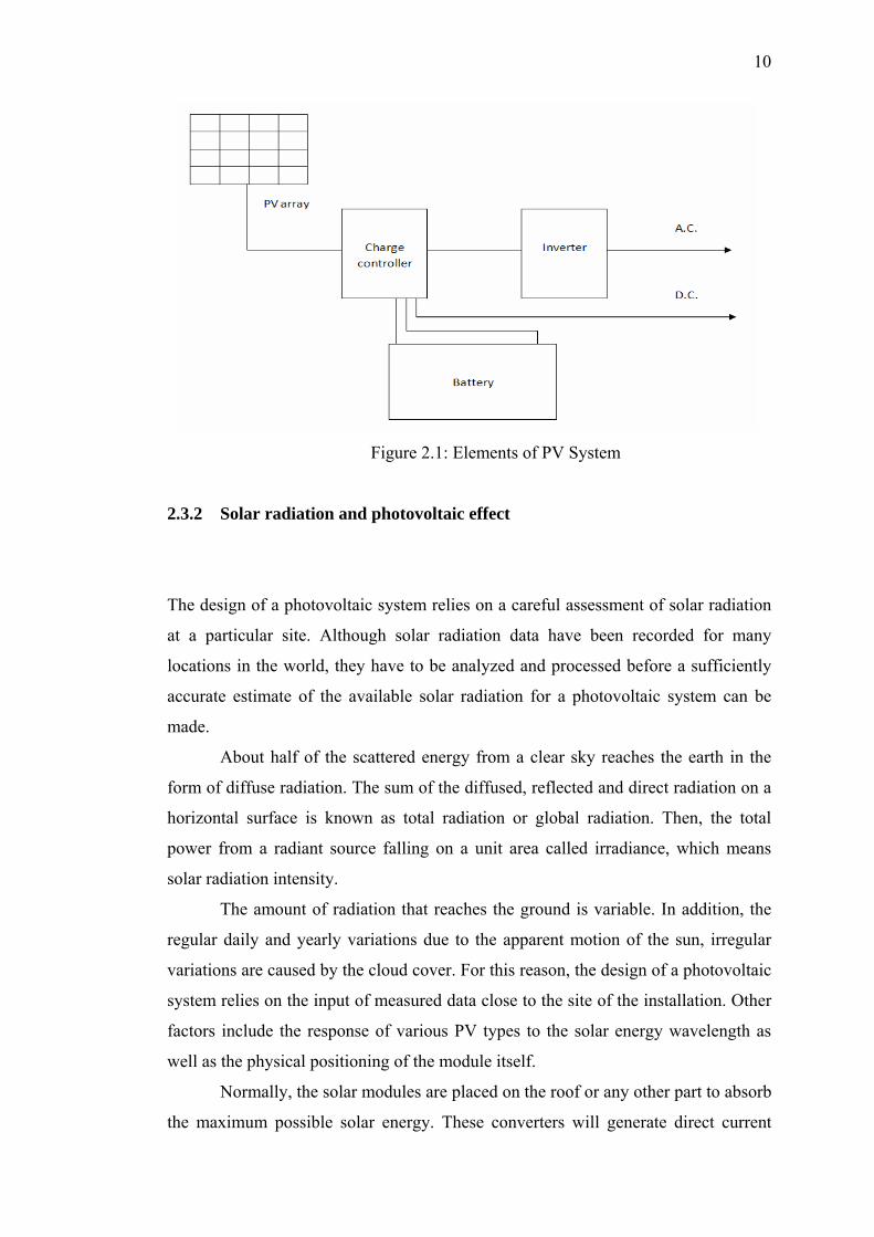
2.3.1 Photovoltaic system
A photovoltaic system broadly normally consists of photovoltaic array is comprise a
few numbers to a few hundreds of modules. The sun pointed to PV array and the
charge controller will regulate the power. Then the power will stored at the battery
bank that consisting of deep cycle batteries. Lastly, the inverter will convert the dc
power from array into ac power.
The daily energy output from PV array will vary depending on its size,
orientation and location, season of the year and the daily weather conditions. Energy
storage is required for the power when sun is not shining. Battery sizing depends on
the application, the daily solar radiation, the total load, peak load and the number of
days which storage required.
The charge controller is placed between the PV array and the storage battery
to prevent the battery from being damaged either due to overcharging or over-
discharging to enhance its life. The power from the PV system is dc and most
electrical appliances work on ac. The inverter is used to convert 12 volts or 24 volts
dc power into 220 volts or 110 volts ac power that usually used in electrical
appliances. Figure 2.1 shows the elements in PV system.
10
Figure 2.1: Elements of PV System
2.3.2 Solar radiation and photovoltaic effect
The design of a photovoltaic system relies on a careful assessment of solar radiation
at a particular site. Although solar radiation data have been recorded for many
locations in the world, they have to be analyzed and processed before a sufficiently
accurate estimate of the available solar radiation for a photovoltaic system can be
made.
About half of the scattered energy from a clear sky reaches the earth in the
form of diffuse radiation. The sum of the diffused, reflected and direct radiation on a
horizontal surface is known as total radiation or global radiation. Then, the total
power from a radiant source falling on a unit area called irradiance, which means
solar radiation intensity.
The amount of radiation that reaches the ground is variable. In addition, the
regular daily and yearly variations due to the apparent motion of the sun, irregular
variations are caused by the cloud cover. For this reason, the design of a photovoltaic
system relies on the input of measured data close to the site of the installation. Other
factors include the response of various PV types to the solar energy wavelength as
well as the physical positioning of the module itself.
Normally, the solar modules are placed on the roof or any other part to absorb
the maximum possible solar energy. These converters will generate direct current

11
from the sun’s ray, solar irradiance. When the sun falls on solid-state, it causes an
electrical charge and direct current flows. There are two systems of utilization, either
the DC power is used directly or the DC power is inverted for AC application. Figure
2.2 shows the direct sunlight to PV modules and convert the sunlight into electricity.
Figure 2.2: PV modules on the roof
The photovoltaic effect is the basic physical and chemical process through
which a PV cell converts sunlight into electricity. Sunlight is composed of photons –
packets of solar energy. These photons contain different amounts of energy that
correspond to the different wavelengths of the solar spectrum. When photons strike a
PV cell, they may pass through it. The absorbed photons are photons are the ones
responsible to generate electricity.
2.4 Theory for the whole system
This subtopic is about the knowledge about the whole system. Sub-subtopic 2.4.1 is
about the common types of PV modules that usually used this day. Sub-subtopic
2.4.2 is explanation about the maximum power point transfer technology (MPPT).
Sub-subtopic 2.4.3 is explanation about the fuzzy MPPT for PV system and subtopic

12
2.4.4 is explanation about the genetic algorithms (GAs) as a tool of FLC optimisation
for a MPPT.
2.4.1 Common types of PV modules
PV cells are generally made either from crystalline silicon, sliced from ingots or
castings, from grown ribbons or thin film, deposited in thin layers on a low-cost
backing. Figure 2.3 shows the process to make a PV cells.
Figure 2.3: Diagram for make a PV cells
Electricity generated from PV modules that can do a lot for people such as for
electrical appliances. PV modules are like the heart of any PV system. The PV
market is expanding rapidly and manufacturers are constantly introducing new and
emerging technologies. The common types that usually used is crystalline modules
and thin film modules.

13
Crystalline PV modules, which are made by grouping a number of individual
solar cells together, are currently used for residential and commercial applications.
One of the reasons why crystalline modules are used so frequently is that they’re
more efficient than other PV technologies. Typical crystalline modules are rated at
11 to 14 watts per square (W/ft²). Some of the higher-efficiency modules are rated in
excess 0f 17 W/ft², which allows a consumer to generate a greater amount of energy
in limited space, like on roof.
Thin film technologies vary in their raw materials and exact manufacturing
processes the thin film only that material on the substrate is extremely thin, ranging
from just nanometers (nm) to a few micrometers (µm) thick.
2.4.2 Maximum power point transfer technology (MPPT)
MMPT is the technology that allows a PV array to deliver the maximum amount of
energy to a battery bank. MPPT charge controllers gained popularity in the early
2000s when manufacturers released highly reliable and accurate version that allowed
users to maximize the charging ability of their PV array and reduce the required PV
array size for battery charging compared to some of the older technology.
2.4.2.1 MPPT works
The maximum power point is the product of P=Vmp x Imp and the units associated
with it are watts (W). The MPP is used to determine the rated power output of the
entire array and the components that connected and the expected energy production
of the PV array. MPPT controllers take the power from PV array at the MPP,
regardless of the required battery voltage and deliver that same amount of power to
the battery because the voltage is reduce from array to the batteries required level. If
the voltage is decreased, the current is increased in order to keep the same power
level. MPPT controller boost current into the battery bank in relation to the current
received from array [8].

14
Figure 2.4: The power gained through the use of MPPT controller
Figure 2.4 shows the location of a typical battery charge set-point. When the
point straight over to the right from that point, the power level associated at the
battery-charging voltage. The difference in the MPP and the power level associated
with the battery-charging voltage represents the increased power output due to the
use of the MPPT technology. The PV array’s power levels move throughout the day
depending on the environmental conditions and MPPT controllers adjust right along
them.
2.4.3 Fuzzy MPPT for PV systems
Fuzzy logic has two different meanings. In a narrow sense, fuzzy logic is a logical
system, which is an extension of multivalued logic. However, in a wider sense fuzzy
logic (FL) is almost synonymous with the theory of fuzzy sets, a theory which relates
to classes of objects with unsharp boundaries in which membership is a matter of
degree. In this perspective, fuzzy logic in its narrow sense is a branch of FL.
Fuzzy Logic Toolbox™ software is a collection of functions built on the
MATLAB® technical computing environment. It provides tools for user to create and
edit fuzzy inference systems within the framework of MATLAB. User can also
integrate their fuzzy systems into simulations with Simulink® software and build

15
stand-alone C programs that call on fuzzy systems user build with MATLAB. This
toolbox relies heavily on graphical user interface (GUI) tools to help user accomplish
their work. FLC contains four main components as shown in Figure 2.5 [9]:
a) The fuzzifier that maps crisp values into input fuzzy sets to activate rules.
b) The rules which define the controller behavior by using a set of IF–THEN
statements.
c) The inference engine which maps input fuzzy sets into output fuzzy sets by
applying the rules.
d) The defuzzifier that maps output fuzzy values into crisp values.
Figure 2.5: Fuzzy inference system
The rules describing the FLC operation are expressed as linguistic variables
represented by fuzzy sets. The controller output is obtained by applying an inference
mechanism [10] which defines:
1) The kind of membership functions.
2) The connections used to link the rules antecedents.
3) The implication function chosen.
4) The rule aggregation operator.
In the case of fuzzy controllers hardware implementation, which is of interest
here, the shapes of the membership functions associated to the FLC linguistic
variables are often piece-wise linear functions (triangular or trapezoidal).

16
It should be noted that the number and shape of the membership functions of
each fuzzy set as well as the fuzzy logic inference mechanism was initially selected
based on trial-and-error methods, in a manner that the region of interest is covered
appropriately by the input data. The idea behind the chosen reasoning in this paper
was, if the last change in the control signal (D) caused the power to rise, keep
moving in the same direction. Otherwise, if it has caused the power to drop move it
in the opposite direction. Subsequently, as it will be explained in the following
sections, a genetic algorithms (GAs) technique was used to tune both of membership
functions and the rule-base set.
The MPPT using the Mamdani’s FLC approach, which uses the min–max
operation fuzzy combination law, is designed in a manner that the control task try to
continuously move the operation point of the solar array as close as possible to the
maximum power point (MPP) [3]. The two inputs of the proposed fuzzy controller
are the tracking error (E) and the change of the error (∆E), which are defined by:
(2.1)
(2.2)
where E and ∆E are the error and change in error, n is the sampling time, p(n) is the
instantaneous power of the PV generator, and V(n) is the corresponding
instantaneous voltage. These inputs are chosen so that the instantaneous value of
E(n) shows if the load operation power point is located on the right or in the left
compared to the Pmax actual position. While ∆E(n) expresses the moving direction
of this operation point (see Figure 2.4).
The output variable is the pulse width modulation (PWM) signal called D,
which is transmitted to the boost DC/DC converter to drive the load. After the rules
have been applied, the center of area as the defuzzication method is used to find the
actual value of (D) as a crisp output.

17
2.4.5 Genetic algorithms (GAs) as a tool of FLC optimization for a MPPT
The genetic algorithms are based on concepts of evolutionary theory, and provide an
effective way of searching a large and complex solution space to give close to
optimal solutions much faster than random trial-and-error methods. They are also
generally more effective at avoiding local minima than differentiation-based
approaches. The basic mechanism of a GA can be simply described as follows [9]:
1) Define the string of a chromosome: The string of searching parameters for the
optimization problem should be defined first. These parameters are genes in a
chromosome, which can be binary coded or real coded. Different
chromosomes represent different possible solutions.
2) Define the fitness function: The fitness function is the performance index of a
GA to resolve the viability of each chromosome. The design of the fitness
function is according to the performance requirements of the problem such as
convergence value, error, rise time and others.
3) Generate an initial population: A set of chromosomes should be randomly
generated before using a GA operation. These chromosomes are called the
initial population. The size of the population is chosen according to the
complexity of the optimization problem. Generally speaking, larger values
require fewer generations to converge to a solution. However, the total
computation time depends also on the number (N) of used generations to
reach the algorithm’s convergence.
4) Generate the next generation or stop: GAs use the operations of
reproduction, crossover and mutation, as detailed in figure 2.6 to generate the
next generation. From generation to generation, a maximum value of the
fitness value is achieved.

18
Figure 2.6: Basic mechanism of genetic algorithm
Genetic algorithms as just described can be used to tune the fuzzy controller
parameters like the structure of rules and membership functions to find those
parameter values that are optimal with respect to the design criteria [11]. The
optimization of these two entities can be done separately, which may result in a
suboptimal solution, because the design parts are mutually dependent by using GA’s
to design both parameters simultaneously [12], the two elements of fuzzy controllers
can be fully integrated to deliver a more finely tuned, high performance controller.
Generally, designing a fuzzy logic controller involves two major steps;
structure identification and parameter identification. Structure identification is the
process of choosing a suitable controller structure, such as the size of the fuzzy rule-
base. Parameter identification then determines the value of the parameters of a fuzzy
controller, such as the shape of the fuzzy membership functions and the contents of
the fuzzy rule-base. In the following section a demonstration is given of how to get
over the step of parameter identification by using the GAs optimization approach, in
a manner that optimal or near optimal fuzzy rules and membership functions can be
selected without a human operator’s experience or a control engineer’s knowledge.
The assumptions used and the constraints introduced to simplify this process are also
explained.
19
CHAPTER 3
METHODOLOGY
3.1 Introduction
This chapter will describe the methods in this project. This project implementation
will divided into 2 parts in order to make everything more systematic, manageable
and easier to troubleshoot. Subtopic 3.2 is about the overall process during project
verification and analysis. Subtopic 3.3 is about the detail process to design FLC –
GA based structural optimization. Subtopic 3.4 is about the data solar collection that
will be used in the photovoltaic system.
20
Design MPPT PV module
FLC – GA based structural optimization
Variation <1000 W/m²
Yes
No
Start
Power & irradiation < test step response
End
Build PV module and fuzzy MPPT
Verification & simulation
No
Yes
Build membership and rule base
Test step response & MPPT response
Figure 3.1: Flowchart of overall project verification and analysis
21
3.2 Overall project verification and analysis
In this part, the software that will be used in this project has been work. Fuzzy logic
toolbox in the MATLAB Simulink for as one of MPPT method has been studied
about it criteria and how to use it. As shown in Figure 3.1, firstly design MPPT PV
module. In order to test the robustness of the design fuzzy-based MPPT, the various
parts of the PV system will be design using MATLAB-Simulink. Then compute FLC
– GA based structural optimization. The system detail will be elaborated in subtopic
3.3. Build the membership function and rule base using Fuzzy Inference System
(FIS) editor.
After that, build PV module and fuzzy MPPT in Matlab Simulink. First
characteristic for test robustness is test verification of the inter-compatibility of the
new design MPPT. The system should response normally to the external excitation.
The second characteristic is the controller step response and also GA optimized FLC.
The variation should be less than 1000 W/m². To evaluate the MPPT performance a
test is carried out, related to the examination of the implemented controller’s
robustness with respect to the rapid change of the solar irradiation. The power
irradiation result should be less or similar with the step response result.

22
Figure 3.2 : Flowchart of the system detail for FLC – GA based structural
optimization

23
3.3 FLC – GA based structural optimization
Figure 3.2 is explanation about how to optimize the GA value. First, initialize the
parameter for GA and FLC. Divide the input and output space of the system to be
controlled into fuzzy region. Then set the random initial population of n string (for n
parameter) of the length L is created by using bit string (0 and 1) for each input and
output region. Each string is decoded into a set of parameters that it represents to find
the membership function and fuzzy rule set parameter. This set of parameters is
passed through a numerical model of the problem space. The numerical model gives
out a solution based on the input set of parameters. By using below equation to find
the base value for decode value:
(3.1)
where
b = Number in decimal form that is represented in binary form
L = Length of the bit string
Xmax and Xmin = User defined constant between which Xi vary linearly
The fitness values are determined for each string in the entire population of
strings. The fitness evaluation for GA can be done using fitness function of the GA
by using global optimization toolbox in matlab. Therefore, the fitness function of the
GA for each individual is defined as follows:
The optimization also can be done by GA on the minimization of integral absolute
error ( IAE ) given by :
(3.2)
where
e(t) = P(t)expect – P(t)PV
P(t)expect = Maximal theoretical delivered power i.e., T = 25 OC and G = 1000 W/m2
P(t)PV = Instant power provided by the pv module

24
The fitness values are scaled so as to distinguish the individual for which the fitness
value is calculated. The fitness measure defined by:
(3.3)
The IAE value is relatively small compared to 1000, so minimizing IAE is
equivalent to maximize fitness expression. Build the membership function using base
value and choose the best fitness value for each string. With these fitness values, the
three genetic operators are used to create new generation of string. The new set of
strings is again decoded and evaluated using three basic genetic operators. This
process is continued until convergence is achieved within population.
The operations of reproduction, crossover and mutation are used in order to
generate the next generation. Reproduction is the process by which strings with
better fitness values receive correspondingly better copies in the new generation. The
second operator, crossover, is the process in which strings are able to mix and match
their desirable qualities in random fashion. The third genetic operator, mutation is
used when reproduction and crossover may not be able to find the optimum solution
to a problem. From generation to generation the maximum value of the fitness value
is achieved. During the creation of a generation it is possible that the entire
population of string is missing a vital bit of information. So the value at certain string
location can change (changed to zero or vice versa). Use a FLC to assess the set of
fuzzy rules and assign a value to each generated set of fuzzy rules. Stop generating
new set of fuzzy rules once some performance criteria are met.
3.4 Data solar
Sub-subtopic 3.4.1 is the measured data voltage (real time) from the PV system in
Power System Lab. Sub-subtopic 3.4.2 is the measured power for solar. Sub-subtopic
3.4.3 is the measured irradiance for solar irradiation analysis. Each type of data taken

55
REFERENCES
[1] A. H. Haris, "Grid-Connected and Building Integrated Photovoltaic :
Application Status & Prospect for Malaysia," Master Builder , Pusat Tenaga
Malaysia, 2006.
[2] C. Lee, "Fuzzy Logic in Control System : Fuzzy Logic Controller - Psrt I,"
IEEE Trans. Syst. Man Cybernet, pp. 404-435, 1990.
[3] K. N. a. S. P, "Implementation of Maximum Power Point Tracking Using Fuzzy
Logic Controller for Solar-Powered Light Flasher Applications," in The 47th
IEEE International Midwest Symposium on Circuits and Systems, Hiroshima,
2004.
[4] M. a. M.A.S.Masoum, "A new fuzzy-based maximum power point tracker for
photovoltaic applications," Iranian Journal of Electrical & Electronic
Engineering, vol. I, 2005.
[5] S. S. a. G.Balasubramaniam, "Fuzzy Logic Controller for the Maximum Power
Point Tracking in Photovoltaic System," International Journal of Computer
Appplications, vol. 41, no. 12, 2012.
[6] M. E. a. H. I.Okumus, "Fuzzy Logic Controlled Buck-Boost DC-DC Conveter
for Solar Energy-Battery System," Turkey, 2011.
[7] P. a. K. C.S.Chin, "Optimisation of fuzzy based maximum power point tracking
in PV system for rapidly changing solar irradiance," Global Hournal of
Technology & Optimization, vol. II, 2011.
[8] S. C. T. a. A. C.Larbes, "Genetic algorithms optimiszed fuzzy logic control for
the maximum power point tracking in photovoltaic system," Algeria, 2009.
[9] M. a. R. Stonier, "Genrating Fuzzy Rules by Genetic Algorithm," in IEE

56
International Workshop on Robot and Human Communication, Australia, 1994.
[10] A. J. a. M. R.Ahmadian Majin, "Speed Improvement of MPPT in Photovoltaic
Systems by fuzzy Controller and ANFIS Reference Model," in M.S. Student,
Shahid Bahanor University of Kerman, Process Control and Optimization
Research Center and Technical College of Ilam, Iran.
[11] a. H. W. Jiyong Li, "Maximum power point tracking of photovoltaic generation
on the fuzzy control method," China, 2008.
[12] H. A. m. H. A. E. h. a. M. E. E. K. S. Mohamed M. Algazar, "Maximum power
point tracking using fuzzy logic control," Electric power and energy systems,
pp. 21-28, 2012.
[13] I. P. a. Y. K. Lo, "A fuzzy control maximum power point tracking photovoltaic
system," IEEE International Conference on Fuzzy Systems, 2011.
[14] R. R. a. R. M. Pandiarajan N, "Application of curcuit model for photovoltaic
energy conversion system," India.
[15] C. Q. a. Z. Ming, "Photovoltaic module simulink model for a stand-alone PV
system," in 2012 International Conference on Applied Physics and Industrial
Engineering, China, 2011.
[16] F. M. Gonzalez-Longatt, "Model of Photovoltaic Module in Matlab," in
American Student Congress of Electrical, Electronic and Computer Engineering
, 2005.
[17] C. S. T. a. Y. J. S. Huang Liang Tsai, "Development of Generalized
Photovoltaic Model Using MATLAB/SIMULINK," in Proceeding of the World
Congress on Engieering and Computer Science, USA, 2008.
[18] R. Mayfield, "Photovoltaic Design & Installation for Dummies," in Wiley
Publishing, Inc., 2010.
[19] J. R. Timothy, "Fuzzy Logic with Engineering Applications," in John Wiley &
Sons Ltd., 2004.
[20] C. S. S. S. B. A. Jime´nez, "Hardware Implementation of a General Purpose
Fuzzy Controller," in IFSA, 1995.
[21] C. G. E. Karr, "Fuzzy Control of pH using Genetic Algorithms," in IEEE
Transactions on Fuzzy System 1 (1), 1993.
57
[22] A. M. E. Homaifar, "Simultaneous Design of Membership Functions and Rule
Sets for Fuzzy Controllers using Genetic Algorithms," in IEEE Transactions on
Fuzzy Systems 3 (2), 1995.
[23] R. L. a. S. E. Haupt, Practical Genetic Algorithms, New York: Wiley-
Interscience, 1998.
[24] X. Q. a. H. Li, "Application of Fuzzy Logic and Immune Response Feedback
for PV Generating System," in Taiyuan Univerity of Science & Technology,
China, 2010.
[25] A. E.-S. A. Nafeh, "Fuzzy Logic Operation Control for PV-Diesel-Battery
Hybrid Energy System," in Electronics Research Institute, Egypt, 2009.
[26] S. L. a. D. Rekioua, "Modeling and Simulation of a Photovoltaic System using
Fuzzy Logic Controller," in Department of Electrical Engineering, University of
Bejaia, Algeria, 2009.
[27] S. a. G. V. Pai, Neural Networks, Fuzzy Logic and Algorithms ( Synthesis and
Aplications), India: Prentice Hall, 2007.
[28] L. Lin, Network Models and Optimization ( Mulyiobjective Genetic Algorithms
Approach), London: Sprienger - Verlag London Limited, 2008.