fx-familyloge(nr.125) calculatesthenaturallogarithm infloatingpoint sort2(nr.149) sorttabulateddata...
TRANSCRIPT

The world’s favoritemicro PLCs
10Million FX PLCsWorldwide /// Over 30 Years Experience ///Expanded Micro PLC Control /// Networking Solutions ///Analog Solutions /// Positioning Solutions ///
FX-FamilyMELSEC PLC

Global Leader
Global leader /// Global leader /// Global leader /// Global leader /// Global
10 Million FXThe FX Family of PLCs is the PLC of choiceacross theworld, industriesandapplications.
Mitsubishi Electric has always workedclosely with its customers to design thePLC that they want for their applications.The manufacturing and use of 10 millionFX CPUs is a demonstration that thisclose working relationship has deliveredquality, reliability and the product that cus-tomers want.
Over 30 YearsThe FX Family of PLCs has been an impor-tant part of control engineering for over30 years. Throughout its history, the pro-duct has evolved from the original F Seriesinto today's current FX3G series.
The FX Family has proven to be highly reli-able and it consistently improves its com-patibility with previous PLC generations.
Number 1 inthe worldMitsubishi Electric was shown to be thelargest volume producer of PLCs in theworld following the 2004 WorldwidePLC survey by the respected Americanautomation research company ARC.
The MELSEC FX3U/FX3UC series are the third generation on programmable controllers of the Mitsubushi Electric FX family.They offer improved network capability and solutions for positioning tasks.
ARC is protected by ARC Advisory Group copyright 20042

Contents
What makes a world leading PLC? 4-5
Range overview 6
FX3U/FX3UC, a new concept in PLCs 7-9
FX3G, an automation standard 10
FX1N, the modular micro 11
FX1S, micro control 12
Programming and software 13
Networking 14
Analog solutions 15
Positioning solutions 16
Displays solutions 17
Applications 18
Section 2: Technical Informations
/// Contents /// Contents /// Contents /// Contents /// Contents /// Contents
3

World leading PLCs ///World leading PLCs ///World leading PLCs ///World l
Global useWide range power supply means yourFX solution will work all over the world.
What makesa world leading PLC range?
InternationalacceptanceShipping approvals such as Lloyds, GermanLloyds, ABS, RINA, Det Norse Vetaritas, forexample plus CE and E1 compliance forLow Voltage and EMC directives as well asmanufacturing to Automotive industryquality levels, make the FX Family PLCsproducts to trust.
Flexible designThe FX Family is designed so that the mainPLC CPU acts as a platform to which youcan add and customize the special func-tions you need –making every FX your per-sonal PLC.
4
Adapter or "ADP" units are usedon the left hand side of themain PLC unit.
Memory cassette port is locat-ed under the removable frontcover.
Optional communication boardsare available in USB, RS232C,RS422 and RS485 formats. The RUN/STOP switch has
become a familiar feature withall FX Family PLCs.
The standard RS422 Mini-DINprogramming port can also beused for HMI connection.

eading PLCs ///World leading PLCs ///World leading PLCs ///World leading
EasyProgrammingThe FX Family incorporates an easy pro-gramming concept where several complextasks can be reduced to a single instruction.
Fast and reliableFX PLCs continually push the limits ofhigh speed operation to process yourapplications more effectively and accurately.
CompatibilityThe FX Family of PLCs continues to raisethe level of backward compatibility withmany existing FX PLC programs beingtransferable. And in later models, sharingcommon peripherals and special functionblocks means even greater protection foryour investment in both FX and themachine or process being controlled.
5
Main base unit where CPU,I/O and power supply arecontained in a single unit.
All FX PLC units can be mountedon a DIN rail or directly mountedwith screw fixings.
Simple ribbon con-nection links eachunit together.
Bright LED lamps indicate I/Oand power status.
Special function blocks canbe added to the right handcommunications bus ofthe PLC.

The power to perform /// The power to perform /// The power to perform /
The power to perform
Asolution forevery applicationMicro PLCs have opened up a world ofopportunities in Industrial Automation dueto their small size and low cost. Now manyapplications benefit from enhanced per-formance, easier manufacturing, mainte-nance and greater reliability.
The FX Family has been a part of this revo-lution for over 30 years and has developedand redeveloped a range of products tosuit most applications. The FX Family con-sists of four main ranges which are distinctand independent but compatible.
Depending on your application and controlneeds, you can choose from; the simpleFX1S CPU, the modular FX1N range, thepowerful FX3U and now the current anddynamic FX3G.
With the FX Family there really is a solutionto most applications.
The FX Family of PLCs builds on previous performance and capability, ensuring you have a comprehensive range of control and automationoptions to choose from.
Summary table of FX PLCsNote * : When networked with CC-Link or AS-Interface (Discrete I/O, maximum 256)Note **: When networked with CC-Link or AS-Interface (Discrete I/O, maximum 128)
/FX3UCUltra high speed, maximumperformance and a simplifieddesign concept make this theultimate micro PLC.
FX3GAdvanced control, multiplecommunication possibilitiesand a wide range of optionsmake this PLC an industryleader.
FX1NThis powerful micro bringsthe flexibility of the modularPLC design concept but, withthe ease of use typical ofFX Family PLCs.
FX1SA compact micro controllerfor simple applications, sup-ported by a strong communi-cations capability.
Performan
ce
I/O
6
Model FX1S FX1N FX3G FX3U FX3UC
Power supply 100–240 V AC,24 V DC
100–240 V AC,12-24 V DC 100–240 V AC 100–240 V AC,
24 V DC 24 V DC
Maximum I/O 30(34 optional)
128(132 optional) 256** 384* 384*
Digital I/O Relay/Transistor
Relay /Transistor
Relay /Transistor
Relay /Transistor Transistor
Cycle period/logicalinstruction
0.55 µs 0.55 µs 0.21 µs or 0.42 µs 0.065 µs 0.065 µs
PLC programmemory 2 k steps 8 k steps 32 k steps 64 k steps 64 k steps
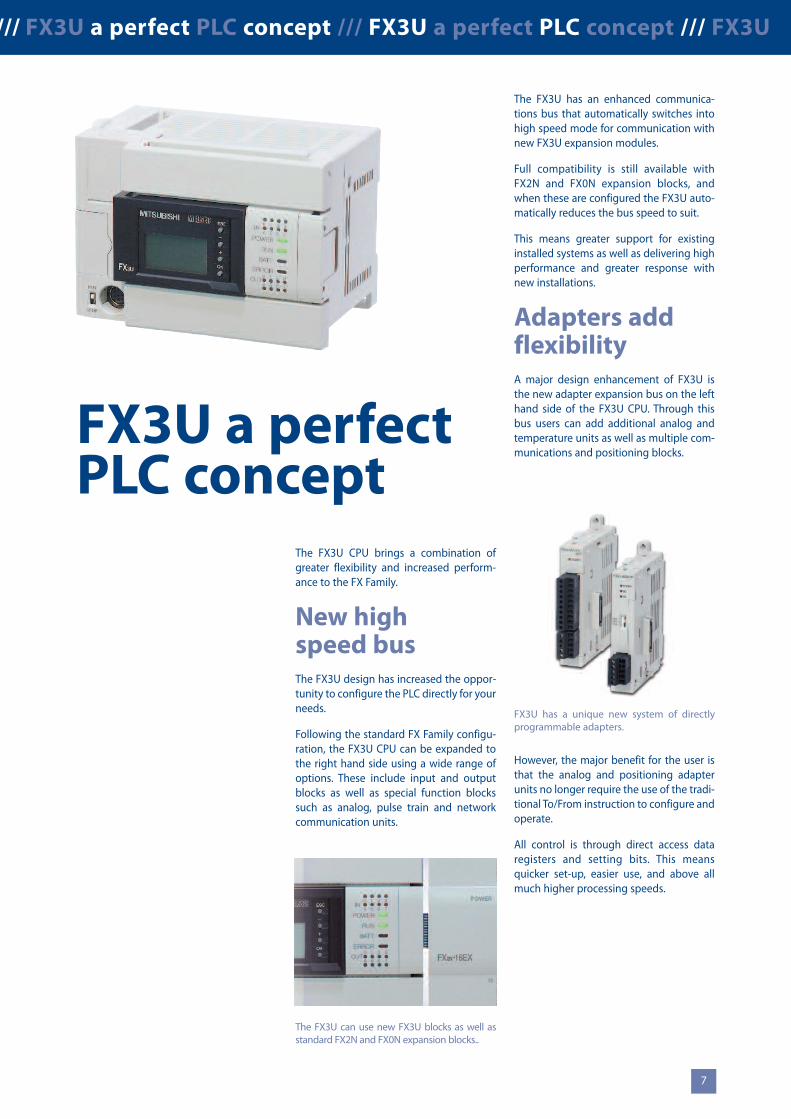
The FX3U has an enhanced communica-tions bus that automatically switches intohigh speed mode for communication withnew FX3U expansion modules.
Full compatibility is still available withFX2N and FX0N expansion blocks, andwhen these are configured the FX3U auto-matically reduces the bus speed to suit.
This means greater support for existinginstalled systems as well as delivering highperformance and greater response withnew installations.
Adapters addflexibilityA major design enhancement of FX3U isthe new adapter expansion bus on the lefthand side of the FX3U CPU. Through thisbus users can add additional analog andtemperature units as well as multiple com-munications and positioning blocks.
However, the major benefit for the user isthat the analog and positioning adapterunits no longer require the use of the tradi-tional To/From instruction to configure andoperate.
All control is through direct access dataregisters and setting bits. This meansquicker set-up, easier use, and above allmuch higher processing speeds.
/// FX3U a perfect PLC concept /// FX3U a perfect PLC concept /// FX3U
FX3U a perfectPLC concept
The FX3U CPU brings a combination ofgreater flexibility and increased perform-ance to the FX Family.
New highspeed busThe FX3U design has increased the oppor-tunity to configure the PLC directly for yourneeds.
Following the standard FX Family configu-ration, the FX3U CPU can be expanded tothe right hand side using a wide range ofoptions. These include input and outputblocks as well as special function blockssuch as analog, pulse train and networkcommunication units.
The FX3U can use new FX3U blocks as well asstandard FX2N and FX0N expansion blocks..
FX3U has a unique new system of directlyprogrammable adapters.
7

FX3U/FX3UC a perfect PLC concept /// FX3U/FX3UC a perfect PLC concept /// F
FX3U/FX3UC.More power.More performance.
Increased I/OcapacityWith enhanced networking functions, theFX3U/FX3UC requires an increased input/output (I/O) range. FX3U/FX3UC can sup-port systems with combined local I/O andnetworked I/O up to a total of 384 I/Opoints. For users, this means increased sys-tem control and added possibilities foradvanced networks.
In addition FX3U/FX3UC also fully sup-ports Profibus/DP as well as Ethernet usingTCP and UDP protocols.
Up to 4.5times fasterThis means the PC MIX value has beengreatly improved with basic instructionsnow being processed in 0.065 µsec.
For users this means quicker programresponse and more accurate process per-formance as inputs, outputs and actionsare processed and monitored more timesper second.
8 times morememoryFX3U/FX3UC comes with a standard inter-nal memory of 64 k steps, which is 8 timesmore memory than FX2N.
More memory means users can write larg-er and more complex programs, storemore data in file registers, or take greateradvantage of using IEC 61131-3 style pro-gramming tools.
5 times moredata storageWith a larger program memory comes theneed for more operational devices such astimers, state flags, auxiliary relays and dataregisters. The FX3U/FX3UC has increasedcapacity in all of these major areas makingprogram construction easier. Data registercapacity has increased by a factor of5 reflecting the needs of users who have anincreased requirement to log operationinformation against products or batches ofproducts being manufactured.
A typical example of this can be found inthe Food and Pharmaceutical industries.Here exact process data such as oven tem-peratures and cooking times or quantitiesof ingredients mixed need to be storedagainst production batches – all thisrequires increased data handling and datacapacity within the PLC.
75 newinstructionsThe FX3U/FX3UC has 75 new instructionsin comparison with FX2N. This now makesavailable 249 instructions for program cre-ation. All of the instructions follow the tra-ditional FX Applied instruction conceptdesigned to make the task of applicationbuilding and program writing easier andquicker, with less chance for errors.
FX3U/FX3UC provides additional I/O and networking capacity.
FX3U/FX3UC offers increased resources aswell as increased performance.
FX3U/FX3UC provides increased performancein all areas.
Note: 4.5 times increase in speed is measured under the fol-lowing conditions: program capacity=16 k step, with an I/Ousage of 144 points. Program scan time is then; FX3U/FX3UC:4.6 ms and FX2N: 21.0 ms, an increase in processing speed of4.56 times.
8
FX3U/FX3UC Base Unit Expansion I/O
Network masterMaximum256 I/O
Remote I/O Remote I/O Remote I/O
Remote network stations
Maximum256 I/O
System Maximum384 I/O
Basicinstruction
Appliedinstruction (MOV)
FAST
FAST
Auxilliary Relay (M) 7680 points3072 points
4096 points1000 points
512 points256 points
40768* points8000 points
State Flags (S)
Timers (T)
Data Registers (D)
*Includes R Registers

FX3U/FX3UC a perfect PLC concept /// FX3U/FX3UC a perfect PLC concept ///
New instructions include greater controlover data processing with a range of newcomparison and string manipulation com-mands.
Simple highspeedpositioningThe FX3U/FX3UC has been designed withsix high speed counters that can each countup to 100 kHz simultaneously per channel.This, combined with three 100 kHz pulsetrain outputs, means users can directly con-figure simple 3-axis positioning systemswithout the use of additional modules.
However, the new high speed counter ADPand pulse train ADPs can provide theFX3U/FX3UC with maximum positioningperformance. Each unit can process signalspeeds of up to 200 kHz.
A greatcommunicatorFX3U/FX3UC has strengthened the com-munications capability of the FX Familyeven further.
The new adapters allow up to three RScommunication channels to be operatedsimultaneously allowing multiple HMIs tobe connected to a single FX3U/FX3UC CPUor combinations of HMIs, third partydevices and programming tools – thechoice is yours.
The FX3U/FX3UC also supports a widerange of network options includingAS-interface, Profibus-DP, CC-Link,DeviceNet, CANopen as well as Ethernet.
The FX3UC is the ideal choice for applica-tions where there is not much space for thecontroller hardware. The smallest base unitwith 8 digital inputs and 8 transistor out-puts takes up just 27 % of the spacerequired for a comparable FX3U unit – andyet the FX3UC incorporates all the featuresof the FX3U.
The connections for the FX3UC inputs andoutputs on the front side can be wired withribbon cable connectors. For this purposesystem cabling sets and remote I/O termi-nal blocks for easy and fast connections areavailable.
LOGE (Nr. 125)Calculates the natural logarithmin floating pointSORT2 (Nr.149)Sort tabulated dataTBL (Nr. 152)Batch data positioning modeBAND (Nr.257)Defines a band or range of validnumbersIVWR (Nr.273)Write parameter to inverter
Some examples of new instructions fromthe FX3U/FX3UC.
Adaptermodules increase positioningperformance.
9
FX3U/FX3UCat a glanceI/O range16–384 (Discrete I/O, maximum 256)Programmemory64 k steps (standard)Basic instruction processing0.065 µsec/logical instructionAnalog signal processingUp to 80 analog inputs,Up to 48 analog outputsAnalog resolution8, 12 and 16 bitsAnalog options19 analog input, output and tempera-ture blocks availablefor selectionPositioningInternal:6 high speed counters (100 kHz)2 high speed counters (10 kHz)3 pulse train outputs (100 kHz),transistor unit onlyExternal (FX3U only):High speed counter block (50 kHz)High speed counter ADP module(200 kHz)Pulse train ADP (200 kHz)Pulse train output block (1 MHz)
FX3U/FX3UC has a range of flexible communication options.
GOT1000
RS 422
USB
RS 485
Inverter 1
Inverter multidrop
Inverter 8
RS 232

FX3G powerful micro control /// FX3G powerful micro control /// FX3G ///
FX3G anindustry standard
CustomizedcontrolThe FX3G is an introductory compact PLCand is the newest addition to the FX3series, designed for simple yet perform-ance-critical applications that require dis-crete control of up to 128 local I/O or up to256 I/O with CC-Link remote I/Os.Incorporating innovative FX3 series tech-nology the customer is presented with asuite of benefits. These include a large pro-gram memory to implement sophisticatedalgorithms plus high speed execution toenhance system productivity.
Highly flexibleA dual bus architecture provides flexibleexpansion possibilities and with the abilityto handle analog, high speed, positioning,and inverter control, the FX3G is able tosuccessfully adapt to a range of applica-tions in industry areas such agriculture,water processing, material handling, foodprocessing and more.
The greatcommunicatorWith a wide range of network and serialprotocols available, such as Ethernet,CC-Link and Modbus, the FX3G enablesseamless integration and data communica-tions between both Mitsubishi Electric andthird-party devices. Furthermore, a built-inUSB port permits convenient connectionto any PC or laptop.
FX3G at aglanceI/O range14–256 (Discrete I/O, maximum 128)Programmemory32 k steps (internal)Basic instruction processing0.21 µs or 0.42 µs/logical instructionAnalog signal processingUp to 74 analog inputsUp to 41 analog outputsAnalog resolution8, 12 and 16 bitAnalog options19 analog input, output andtemperature blocks available forselectionPositioningInternal:Up to 4 high speed counters (max. 10kHz)up to 2 high speed counters (max. 60kHz)up to 3 (2) pulse train outputs (100 kHz)
FX3G PLCs are used in many applications for processing and packaging as well chilled storageand transportion of food items.
Since its launch, the FX3G has beena standard of micro PLC control.
FX3G has the versatility to handle applicationsfrom awide range of industries.10

/ FX1N modular micro /// FX1N modular micro /// FX1N modular micro ///
FX1N themodular micro
The FX1N provides a simple introductionto modular micro control offering compre-hensive functionality and expansionoptions.
Compatibilitycuts costsThe FX1N provides many user benefitsincluding excellent compatibility withother FX Family PLCs. The FX1N is upward-ly compatible to the FX2N/FX3G usingmany of the FX2Ns I/O and special functionblocks. It also shares the same program-ming structure as the FX1S. This meansthat users benefit from learning and usingone PLC programming syntax; resulting infaster program development and reducedprogramming errors.
In addition, users benefit from a reducedstock and spare parts requirement as theFX1N uses the same expansion boards asthe FX1S and the same special functionand expansion I/O blocks as the FX2N.
FX1N at aglanceI/O range14–132Programmemory8 k steps (standard)Basic instruction processing0.55 µsec/logical instructionAnalog signal processing66 analog inputs33 analog outputsAnalog resolution8, 12 and 16 bitsAnalog options12 analog input, output andtemperature blocks availablefor selectionPositioningInternal:2 high speed counters 60 kHz,4 high speed counters 10 kHz2 pulse train outputs (100 kHz),transistor unit only
PowerfulperformanceThe FX1N saves space, cost and engineer-ing time with the use of powerful, built in,positioning tools such two 100 kHz pulsetrain outputs and up to two 60 kHz highspeed counters. These can be used to cre-ate simple 2-axis positioning systems,linked to servo amplifiers or stepper motordrivers without the need for additional PLChardware saving space, cost and engineer-ing time.
The FX1N offers comprehensive expansionoptions.
11
FX1N has six shipping approvals. It has been used in applications from controlling temperaturein containers to managing diesel engines.

FX1S micro control /// FX1S micro control /// FX1S micro control /// FX1S //
FX1S micro control
Fit and forgetTypically FX1S applications are small,embedded control functions that are hiddenaway or unaccessible under normal mainte-nance activities. This is why the FX1S hasbeen designed to be a robust low mainte-nance PLC. Features such as the mainte-nance free, 2000 step EEPROMmemory andreal time clockmanagement all help tomakethe FX1S a self managing system, reducingthe impact on themaintenance engineer.
Remote controlThe FX1S has an additional range of BDexpansion boards providing RS232,RS485 and RS422 communicationsoptions. These can be used to connect andcontrol various third party products suchas bar code readers or panel printers.
SimpleprogrammingThe FX Family has a simple programmingstructure combining Basic and Appliedinstructions. The Basic instructions arecommon to all FX Family PLCs. Appliedinstructions provide the specialist controloptions such as data comparisons, PID andcommunications control, all of which areavailable on FX1S. As each FX PLC rangeincreases in capability (FX1S, FX1N, FX3G,FX3U/FX3UC) so do the number of avail-able Applied instructions.
FX1S at a glanceI/O range10–34Programmemory2 k steps (standard)Basic instruction processing0.55 µsec/logical instructionAnalog signal processingUp to 2 pointsAnalog resolution12 bitsAnalog options2 analog input BD board1 analog output BD boardPositioningInternal:2 high speed counters 60 kHz,4 high speed counters 10 kHz2 pulse train outputs (100 kHz),transistor unit only
FX1S offers communication and real timecontrol from a single unit.
FX1S has been used in a wide range of embedded control applications.
12
Example of connectivity to 3rd party products

/// Programming /// Programming /// Programming /// Programming ///
Progressivesoftware conceptsThe Mitsubishi FX PLC Family has aworldwide reputation for reliability, per-formance and ease of use. These keyvalues have also been used to formMitsubishi’s integrated software con-cept, MELSOFT.
ProductivitytoolsProgramming software for PLCs is con-stantly evolving. Users are placing morefocus on reusable program code andfunction block concepts. This helpsto reduce errors, reduce programmingtime and to help manage the whole pro-gramming process – increasing overallproductivity.
Simple andintuitive
The key to any good software is that it issimple to use. Mitsubishi’s GX DeveloperPLCprogrammingpackages have achievedthis by using intuitive design.
They also have comprehensive helpfunctions and an advanced communi-cations layer, ensuring safe reliable com-munication to the target PLC.
Choose whatyou needGX Developer offers users the chance toprogram all Mitsubishi MELSEC PLCsfrom a single package. However, forusers who only need support for FXbased systems there is GX Developer FX.
Mitsubishi also provide GX IEC Developerpackages, providing IEC61131-3 compli-ant programming in; Instruction List,Ladder, Function Block, Structured Textand SFC formats. Using standard pro-gramming languages, like IEC61131-3, onlarge programming projects can helpusers save costs by creating reusable PLCcode and Function Blocks.
MELSOFT is a wide range of software solu-tions designed to optimize your plant pro-ductivity.
Often the biggest cost on a project is engi-neering time.
13
GX Developer offers ease of use for program-mers of all skill levels.
One step furtherwith iQWorksMitsubishi Electric's iQ Works software is asuite of four MELSOFT software packagesthat enable intuitive programming andsetup of an iQ Platform system, includingsystem/network configuration, Q and FXSeries programming, Q Motion Controllerand Servo setup, GOT1000 HMI screendesign. This next generation software pro-vides a fully customizable user friendlyenvironment with the developers in mind.
First time user?For users who do not have the time totake local training, there is the option ofusing Mitsubishi’s home study software,FX-TRN-BEG, where PLC programs canbe created, simulated and debugged inthe safety of a PC simulation.
Learning to program can be achieved quicklyusing interactive software.

Networking solutions /// Networking solutions /// Networking solutions /
Networking andcommunication solutions
Applications are often required to inte-grate between each other across a factory,to report production or tracking data backfor office based processing and in somecases be remotely monitored and main-tained when the application is in an inac-cessible location. The FX Family of PLCs hasevolved to match this demand atall levels.
Networksmake senseNetworked solutions to complex applica-tions often make the overall solution easierto achieve and more cost effective. Forexample a conveyor system integratedwith a warehouse pick and place systemmay extend over many hundreds ofmeters, and by using a fieldbus, such as CC-Link, wiring, troubleshooting and mainte-nance can be dramatically reduced.
RemotemaintenanceWith communications technology it is nowpossible to put PLC control in the mostremote locations. Using a PLC with a RS232interface to a telemetry solution, such as aGSM modem, allows the user the ability toremotely monitor and maintain the sys-tem. It can also allow the remote system tosend alarm messages, warnings or generalstatus information back to the user’s cen-tral data processing centre.
EasycommunicationsToday’s FX Family of PLCs share a basiccommunication concept where additionalRS232, RS422 or RS485 communicationsboards can be added to the mainbase unit without increasing the requiredcabinet space. These can then be used forcommunication to various third partydevices like bar code readers, printersand modems.
FX Family PLCs, such as FX1N, FX3G, FX3Uand FX3UC, have a wider range of commu-nications modules. These include optionsfor connection to open and bespoke net-works such as Ethernet, Profibus-DP,CC-Link, DeviceNet, CANopen, AS-interfaceor Modbus for example.
FX Family PLCs have a wide range of communications options.
Example of remote pumping station.
14

Analog solutionsAnalog control is one of the most impor-tant areas for any automation system.Critically for users the concern is to matchthe performance demanded by the appli-cation to the available solutions in a costeffective way.
Where isanalog used?Analog control is widely used. In simpleterms it allows a variable signal to be usedto control items such as a motor’s speed orto sense inputs such as fluid levels.
�� Digital to analog (D-A) control Here a digital PLC value is output as an ana-log signal. It can be used, for example, tosend a speed command to an inverterwhich in turn causes the motor to increaseor decrease speed.
�� Analog to digital (A-D) controlIn this type of control a variable signal issent to a PLC where it is converted in to adirect digital value. An example of thiscould be the measurement of the level of aliquid in a storage tank so that the exactamount of stored liquid can be controlledby the PLC.
�� Temperature controlTemperature control is the third type ofanalog control. An example of use could bewhere the temperature of a furnace ismeasured and compared by the PLCagainst a set range. Additional heating orcooling can then be applied to maintain aconstant temperature.
22 solutions to choose fromThe FX Family offers a wide range of analogsolutions from 1 and 2 channel BD boardsfor FX1S up to 8 channel input blocks likethe FX2N-8AD where temperature, voltageand current input can be mixed on thesame block. FX analog blocks also come ina range of resolutions from 8 bit up to16 bit signal processing. Overall there are22 different analog options available tousers of the FX PLC Family.
With this range of choice and flexibility it issure that there will be a solution here formost applications.
Networking solutions /// Networking solutions /// Networking solutions /// Analog solutions /// Analog solutions /// Analog solutions /// Analog
Example of temperature control.
Analog solutions are an important part of control engineering and can be used to simplify andaccurately control actions happening in the production environment.
Inverter
Example: D-Acontrol can beused to set thespeed of aninverter drivinga motor.
Example: A-D control can be used tocontrol the fill-ing speed of the container.
Example:Temperaturecontrol keepsthe liquid at thecorrect viscosity.
15

Positioning solutions /// Positioning solutions /// Positioning solutions /// Displays /// GOTs /// Displays /// GOTs /// Displays /// GOTs /// Displays ///
Positioning solutions
Using simple positioning solutions canhelp increase the accuracy of the workprocess, reduce waste and rework as well asprovide a higher quality of production.
Typical applicationsSimple positioning applications typicallyinvolve independently controlled opera-tional axis and can sometimes have manyrequirements. In the example of an X-Ytable, a relative position is achieved by driv-ing each axis until its target position isachieved, regardless of what happens withthe other axis. There are two main elementsto achieve this type of positioning control.
�� Pulse train outputsA stream of output pulses can be used asa drive signal to a line driver, steppermotor or servo amplifier, which thencauses the connected motor to performthe positioning activity.
The larger the range of output pulse fre-quencies available means greater speedand/or accuracy is achievable. For exam-ple, if a stepper motor with a larger num-ber of steps is used, the travel distanceper step can be reduced, resulting in anincreased system accuracy.
�� High speed counter inputWhen a motor is being driven, its relativeposition can be controlled by counting thenumber of output pulses.
However, for a more accurate process, reading the actual position from anencoder feedback directly into a highspeed counter is preferred. This helps toovercome issues of backlash and slippageas the actual position is measured and not assumed.
Positioning builtin as standardFX PLCs come with high speed counters(in some cases up to 100 kHz) and pulsetrain outputs (also in some cases up to100 kHz) as standard. The high speedcounters can be configured in single pulse train inputs, The high speed coun-ters can be configured in a single or twophase input.
Pulse train outputs can be configured toprovide continuous pulse streams at differ-ent frequencies or a set quantity of pulsesat a single frequency.
There are also optional modules andadapters that can provide additional highspeed counters with performance up to200 kHz. The same is true for pulse trainoutputs with 200 kHz and 1 Mpps (1 MHz)output options available.
X-Y table for simple shaping
Horizontal drill station Vertical drill station
Example of conveyor belt control.
16
Simple positioning solutions can be effectively managed within a standard FX PLC.

Positioning solutions /// Positioning solutions /// Positioning solutions /// Displays /// GOTs /// Displays /// GOTs /// Displays /// GOTs /// Displays ///
Display solutionsAn increasingly important area of anyautomation solution is the reporting anddisplay of operational information. Thisdata enables operators, maintenanceteams and business managers to makeinformed decisions in the best interests ofthe business.
The right toolfor the right jobFor maximum efficiency, each user requiresaccess to information at their work place ina form that highlights the important datafor them first. This means a range of differ-ent tools are required. As an example, hereare three possible scenarios.
�� The machine operatorMachines often have a lot of manufactur-ing debris around or are subject to hygien-ic cleaning as in the food industry. Any dis-play located in this environment wouldneed to have a high Ingress Protection (IP)rating, indicating a high degree of water-proofness.
It may also be a benefit to the operator tohave a large and clear display to reduce thechances for error from misreading, due topoor light or small fonts being used. It isalso recognized that the use of graphicsalso reduces the chances for reading errorswith complex data.
�� The maintenance teamThe critical information for a maintenanceengineer is the error and diagnostic datawithin the PLC as this is used to diagnoseany process problems. However, additional
information regarding the operational"hours run" or cycles processed, whichcould be called soft information as it is cal-culated on operational parameters, couldallow the maintenance engineer to predictpossible failure and arrange preventativemaintenance.
Access to this data could be through themachine operator's terminal, across a net-work or through a dedicated displaymounted inside or on the control cabinet itself.
�� The business managerIn a production controllers office it wouldbe better to display information through anetwork to their existing desktop PC. Inthis application a piece of software such asan OPC server/client, a Java applet, anActive X control or a SCADA system wouldallow lots of data from lots of sources to bedisplayed in a clear and concise way givingthe production controller the overview ofthe business operation that they need.
The GOT1000 is a typical HMI.
The FX3U-7DM can be directly mountedwithin the PLC (FX3U) or mounted on thefront cabinet.
In the food industry hygiene is very important.
17
Data the wayyou want itMitsubishi offers a wide range of visualizationsolutions from simple data displays such asthe FX3U-7DM, advanced Graphic OperatorTerminals like the GOT1000 Series and E1000Series, and a wide choice of software solu-tions from the MELSOFT software suite.
This powerful combination of hardwareand software means there is a cost effectivesolution for most applications.

Application solutions /// Application solutions /// Application solutions /// Automation solutions /// Automation solutions /// Automation solutions
Where have FX PLCsbeen used?
Customer applications with FX PLCs havebeen wide spread from critical applicationsin pharmaceutical industries to sublimeapplications in the leisure industry.However, the FX PLC Family still remainsthe PLC of choice for many machinebuilders as it is flexible, compact and easyto use, which is why it is so often used.
Here are just a few examples of applicationsthat customers have completed in the past
�� Agriculture– Plant watering systems– Plant handling systems– Saw mill (wood)
�� Building management– Smoke detection monitoring– Ventilation and temperature control– Lift (elevator) control– Automated revolving doors– Telephone management– Energy management– Swimming pool management
�� Construction– Steel bridge manufacturing– Tunnel boring systems
�� Food and drink– Bread manufacture (mixing/baking)– Food processing (washing/sorting/slicing/packaging)
�� Leisure– Multiplex cinema projection– Animated mechatronics(museums/theme parks)
�� Medical– Respiration machine testing– Sterilization
�� Pharmaceutical/chemical– Dosing control– Polution measurement systems– Cryogenic freezing– Gas chromotography– Packaging
�� Plastics– Plastic welding systems– Energy management systems for injection molding machines
– Loading/unloading machines– Blow molding test machines– Injection molding machines
�� Printing
�� Textiles
�� Transportation– Sanitation on passenger ships– Sanitation on rail rolling stock– Fire tender, pump management– Waste disposal truck management
�� Utilities– Waste water treatment– Fresh water pumping
Sanitation management on Eurostar rollingstock.
18
Swimming pools are managed using FX PLCs.

Technical Information Section
ALPHA /// FX1S /// FX1N /// FX3G /// FX3U /// FX3UC ///

2 MITSUBISHI ELECTRIC
System Q FamilyProduct catalogues for programmable logic controllers andaccessories for the further MELSEC PLC series
HMI FamilyProduct catalogue for operator terminals, supervision softwareand accessories
Inverter FamilyProduct catalogue for frequency inverters and accessories
Servo and Motion SystemsProduct catalogue for servo amplifiers and servo motors as well asmotion controller and accessories
Robots FamilyProduct catalogue for industrial robots and accessories
Low Voltage Switchgears
Product catalogue for low voltage switchgears, magneticcontactors and circuit breakers
Automation BookOverview on all Mitsubishi automation products, like frequencyinverters, servo/motion, robots etc.
Brochures
Further Publications within the PLC Range
More information?
This product catalogue is designed to give an overview of the extensive range of FX Family of MELSEC PLCs. If you cannot find theinformation you require in this catalogue, there are a number of ways you can get further details on configuration and technical issues,pricing and availability.
For technical issues visit the www.mitsubishi-automation.com website.
Our website provides a simple and fast way of accessing further technical data and up to the minute details on our products andservices. Manuals and catalogues are available in several different languages and can be downloaded for free.
For technical, configuration, pricing and availability issues contact our distributors and partners.
Mitsubishi partners and distributors are only too happy to help answer your technical questions or help with configuration building.For a list of Mitsubishi partners please see the back of this catalogue or alternatively take a look at the "contact us" section of ourwebsite.
About this product catalogue
This catalogue is a guide to the range of products available. For detailed configuration rules, system building, installation and configura-tion the associated product manuals must be read. You must satisfy yourself that any system you design with the products in this cata-logue is fit for purpose, meets your requires and conforms to the product configuration rules as defined in the product manuals.
Specifications are subject to change without notice. All trademarks acknowledged.
© Mitsubishi Electric Europe B.V., Factory Automation - European Business Group

3MITSUBISHI ELECTRIC
1
2
3
4
5
6
7
CONTENTS ///
System Description� ALPHA and MELSEC PLC system . . . . . . . . . . . . . . . . . . . . . . . . . . . . . . . . . . . . . . . . . . . . . . . . . . . . . . . . . . . . . . . . . . . . . . . . . . . 4� Extension modules and special function modules . . . . . . . . . . . . . . . . . . . . . . . . . . . . . . . . . . . . . . . . . . . . . . . . . . . . . . . . . . 6
1 ALPHA Controllers� Base units . . . . . . . . . . . . . . . . . . . . . . . . . . . . . . . . . . . . . . . . . . . . . . . . . . . . . . . . . . . . . . . . . . . . . . . . . . . . . . . . . . . . . . . . . . . . . . . . 8� Extension units and accessories . . . . . . . . . . . . . . . . . . . . . . . . . . . . . . . . . . . . . . . . . . . . . . . . . . . . . . . . . . . . . . . . . . . . . . . . . . 11
2 MELSEC FX Base Units� FX1S series . . . . . . . . . . . . . . . . . . . . . . . . . . . . . . . . . . . . . . . . . . . . . . . . . . . . . . . . . . . . . . . . . . . . . . . . . . . . . . . . . . . . . . . . . . . . . . 13� FX1N series . . . . . . . . . . . . . . . . . . . . . . . . . . . . . . . . . . . . . . . . . . . . . . . . . . . . . . . . . . . . . . . . . . . . . . . . . . . . . . . . . . . . . . . . . . . . . 16� FX3G series . . . . . . . . . . . . . . . . . . . . . . . . . . . . . . . . . . . . . . . . . . . . . . . . . . . . . . . . . . . . . . . . . . . . . . . . . . . . . . . . . . . . . . . . . . . . . 19� FX3U series . . . . . . . . . . . . . . . . . . . . . . . . . . . . . . . . . . . . . . . . . . . . . . . . . . . . . . . . . . . . . . . . . . . . . . . . . . . . . . . . . . . . . . . . . . . . . . 22� FX3UC series . . . . . . . . . . . . . . . . . . . . . . . . . . . . . . . . . . . . . . . . . . . . . . . . . . . . . . . . . . . . . . . . . . . . . . . . . . . . . . . . . . . . . . . . . . . . 26
3 MELSEC FX Extension Units� Powered compact extension units. . . . . . . . . . . . . . . . . . . . . . . . . . . . . . . . . . . . . . . . . . . . . . . . . . . . . . . . . . . . . . . . . . . . . . . . 29� Unpowered modular extension blocks. . . . . . . . . . . . . . . . . . . . . . . . . . . . . . . . . . . . . . . . . . . . . . . . . . . . . . . . . . . . . . . . . . . . 31
4 MELSEC FX Special Function Modules� Analog modules . . . . . . . . . . . . . . . . . . . . . . . . . . . . . . . . . . . . . . . . . . . . . . . . . . . . . . . . . . . . . . . . . . . . . . . . . . . . . . . . . . . . . . . . . 33� Temperature control modules/Data logger modules . . . . . . . . . . . . . . . . . . . . . . . . . . . . . . . . . . . . . . . . . . . . . . . . . . . . . . 36� High-speed counter modules . . . . . . . . . . . . . . . . . . . . . . . . . . . . . . . . . . . . . . . . . . . . . . . . . . . . . . . . . . . . . . . . . . . . . . . . . . . . 37� Positioning modules . . . . . . . . . . . . . . . . . . . . . . . . . . . . . . . . . . . . . . . . . . . . . . . . . . . . . . . . . . . . . . . . . . . . . . . . . . . . . . . . . . . . . 38� Network modules. . . . . . . . . . . . . . . . . . . . . . . . . . . . . . . . . . . . . . . . . . . . . . . . . . . . . . . . . . . . . . . . . . . . . . . . . . . . . . . . . . . . . . . . 39� Communications modules, Interface modules . . . . . . . . . . . . . . . . . . . . . . . . . . . . . . . . . . . . . . . . . . . . . . . . . . . . . . . . . . . . 45� Adapter boards and communications adapter . . . . . . . . . . . . . . . . . . . . . . . . . . . . . . . . . . . . . . . . . . . . . . . . . . . . . . . . . . . . 46� Interface adapters . . . . . . . . . . . . . . . . . . . . . . . . . . . . . . . . . . . . . . . . . . . . . . . . . . . . . . . . . . . . . . . . . . . . . . . . . . . . . . . . . . . . . . . 49
5 Accessories� Expansion Adapter . . . . . . . . . . . . . . . . . . . . . . . . . . . . . . . . . . . . . . . . . . . . . . . . . . . . . . . . . . . . . . . . . . . . . . . . . . . . . . . . . . . . . . 50� Memory media . . . . . . . . . . . . . . . . . . . . . . . . . . . . . . . . . . . . . . . . . . . . . . . . . . . . . . . . . . . . . . . . . . . . . . . . . . . . . . . . . . . . . . . . . . 50� External Terminal Blocks . . . . . . . . . . . . . . . . . . . . . . . . . . . . . . . . . . . . . . . . . . . . . . . . . . . . . . . . . . . . . . . . . . . . . . . . . . . . . . . . . 51� Power supply units . . . . . . . . . . . . . . . . . . . . . . . . . . . . . . . . . . . . . . . . . . . . . . . . . . . . . . . . . . . . . . . . . . . . . . . . . . . . . . . . . . . . . . 53� Backup batteries, Cables . . . . . . . . . . . . . . . . . . . . . . . . . . . . . . . . . . . . . . . . . . . . . . . . . . . . . . . . . . . . . . . . . . . . . . . . . . . . . . . . . 53� Display modules . . . . . . . . . . . . . . . . . . . . . . . . . . . . . . . . . . . . . . . . . . . . . . . . . . . . . . . . . . . . . . . . . . . . . . . . . . . . . . . . . . . . . . . . . 55
6 Dimensions� Base and extension units . . . . . . . . . . . . . . . . . . . . . . . . . . . . . . . . . . . . . . . . . . . . . . . . . . . . . . . . . . . . . . . . . . . . . . . . . . . . . . . . . 56� Special function modules . . . . . . . . . . . . . . . . . . . . . . . . . . . . . . . . . . . . . . . . . . . . . . . . . . . . . . . . . . . . . . . . . . . . . . . . . . . . . . . . 60� Accessories. . . . . . . . . . . . . . . . . . . . . . . . . . . . . . . . . . . . . . . . . . . . . . . . . . . . . . . . . . . . . . . . . . . . . . . . . . . . . . . . . . . . . . . . . . . . . . 62
7 Software & Programming� Trainings and programming software . . . . . . . . . . . . . . . . . . . . . . . . . . . . . . . . . . . . . . . . . . . . . . . . . . . . . . . . . . . . . . . . . . . . 63� Programming unit . . . . . . . . . . . . . . . . . . . . . . . . . . . . . . . . . . . . . . . . . . . . . . . . . . . . . . . . . . . . . . . . . . . . . . . . . . . . . . . . . . . . . . . 66
Others� Approvals . . . . . . . . . . . . . . . . . . . . . . . . . . . . . . . . . . . . . . . . . . . . . . . . . . . . . . . . . . . . . . . . . . . . . . . . . . . . . . . . . . . . . . . . . . . . . . . 67� Index. . . . . . . . . . . . . . . . . . . . . . . . . . . . . . . . . . . . . . . . . . . . . . . . . . . . . . . . . . . . . . . . . . . . . . . . . . . . . . . . . . . . . . . . . . . . . . . . . . . . 69

4 MITSUBISHI ELECTRIC
FX1SFX1N
8,00
0*
2,00
0
16.0
00*
34
132
256
0.55
–0.
7
0.55
–0.
7
64,0
00
384
0.06
5
FX /FX3U 3UCFX3G
32,0
00
0.21
–0.
42
256
Expandability and Power
The MELSEC FX family is highly flexible,enabling fast and efficient configurationand programming for the application athand.
It is the ideal choice, no matter whetheryou need to install a simple controlapplication requiring 30 I/Os (FX1S) or ademanding, complex system with up to384 I/O points (FX3U).
The use of memory cassettes can expandthe available programming space on someFX Family PLCs while generally providing along term program storage option for allFX PLC users. In addition, memory cas-settes can also allow programs to beswitched at very short notice simply byreplacing the cassette.
There are five series in the MELSEC FXfamily, each of which is designed for adifferent application profile:
� The FX1S SeriesThe MELSEC FX1S series is the inexpensiveentry to the MELSEC FX family. With itssmall dimensions it is also an excellentalternative to relay/contactor controlconfigurations.
� The FX1N SeriesThe CPUs of the FX1N series offer morepower than the FX1S series, plus modular
expansion capabilities. You can choosefrom I/O expansion modules and specialfunction modules for a wide variety ofapplications.
� The FX3G SeriesThe FX3G is an introductory compact PLCand is the newest addition to the FX3series, designed for simple yet perfor-mance-critical applications. Incorporatinginnovative FX3 series technology the cus-tomer is presented with a suite of benefits.
� The FX3U SeriesThe FX3U series gives you the freedom ofmodular expandability, with a wideselection of expansion modules andspecial function modules.
The FX3U is the fastest PLC systems avail-able, with a cycle time of just 0.065 μs perlogical instruction. This gives users apowerful CPU delivering modular PLCperformance in a compact PLC design.
� The FX3UC SeriesThe performance of the FX3UC is the sameas that of the FX3U series, but it has morecompact dimensions. It is the ideal choicefor applications where little space is avail-able for the controller.
Thus the FX3U and FX3UC series give youthe most powerful CPU for your applica-tion and combines all benefits of a com-pact PLC system with the performance ofa modular PLC system.
No. of inputs/outputs
Program steps
Cycle time (µs)
The ALPHA Series
The ALPHA closes the gap between singlecomponents and a PLC system. It com-bines all advantages of a PLC system in avery compact housing and therefore pro-vides a space and cost saving alternativeto relays and contactors.
The ALPHA series is suited to applicationsin industrial machines and in automatedbuilding services.
Key enhancements in the ALPHA2 includea program capacity of 200 function blocks,an extra-large display, expansion optionsand a second communications port. Theinstruction set, includes math operations,PWM and SMS text messaging functions.All this opens up possibilities for analogand temperature control as well as remoteoperation.
The MELSEC FX Family
The MELSEC FX family includes a verycomprehensive range of base and expan-sion modules, enabling you to configurea customised system tailored to yourprecise requirements.
Depending on your application and con-trol needs you can choose from the small,attractively-priced, "stand-alone" FX1S
series, the expandable FX1N series or themore powerful FX3G and FX3U series.
With the exception of the FX1S all FX seriescan be expanded to adapt them to thechanging needs of your installations andapplications.
Network integration is also supported,making it possible for your FX controllersto communicate with other PLCs, control-lers and HMIs. The PLC systems can be con-figured as local stations in MITSUBISHI net-works. In addition these flexible units canalso be used as master or slave units onfieldbus’s like Profibus/DP and CC-Link.
The MELSEC FX Family controllers alsosupport CANopen, DeviceNet,AS-Interface and Ethernet. Special ver-sions with E-Mark label (ECE requestion)are available upon request for vehicleapplication.
ALPHA and MELSEC PLC Systems
/// SYSTEM DESCRIPTION
MITSUBISHIPOWER24V DC
AL2-24MR-D
ESC
OK
1(A)7
+ -6
15
511 12 13 14
410
39
2(B)8
DC INPUT
MITSUBISHI
0 1 2 34 5 6 78 9 10 1112 13 14 15
0 1 2 34 5 6 710 11
IN
OUT
POWER
FX -24MR1N
RUNERROR
100-240VAC
X7 X11 X13 X15X5X3X1S/S X6 X10 X12 X14
X4X2X0NL
24MR-ES/ULY10Y6Y5Y3
COM3 Y4 COM4 Y7 Y11COM2COM1COM024+
Y2Y1Y00V
0 1 2 34 5 6 7
0 1 2 34 5
IN
OUT
POWER
FX -14MR1S
RUNERROR
MITSUBISHI
X7X5X3X1S/S X6X4X2X0NL100-240
VAC
14MR-ES/ULY4Y2Y1Y0
COM0COM1COM2 Y3 Y524V
0V
* Available with optional cassette

5MITSUBISHI ELECTRIC
DIGITALEEIN-/AUSGÄNGE
POSITIONIER-MODULE
KOMMUNI-KATIONS-MODULE
ANALOGEEIN-/AUS-GÄNGE
DIGITALINPUTS/OUTPUTS
POSITIONINGMODULES
COMMUNI-CATIONS-MODULES
ANALOGINPUTS/
OUTPUTSCPUCPU
Digital and special functionmodules – configuration
The options for using digital and specialfunction modules are dictated by the CPUused in the system.
When calculating the number of specialfunction modules you can use in a systemyou must take both the number of digitalmodules and the maximum number ofspecial function modules that can be usedinto account.
The table on the right provides a simplifiedguide to the number of modules you canuse in each system type. More detailedinformation and the basic principles ofsystem configuration can be found in thecorresponding manuals.
FX1S Stand-alone PLC with 10 / 14 / 20 or 30 I/Os;no special function modules but 1 I/O adapter board can be installed
FX1N
PLC with max. 132 I/OsA maximum of 2 special function modules or digital expansion modules with up to32 inputs and outputs (4x8 I/Os or 2x16 I/Os) or one special function module and one digi-tal extension module with up to 16 inputs and outputs (2x8 I/Os or 1x16 I/Os)can be connected.
FX3G
PLC with max. 256 I/OsA maximum of 8 special function modules and digital extension modules with up to128 I/Os can be connected to the right side of the main unit. In addition, a maximum of4 special adapters from the FX3U series can be connected to the left side.
FX3U
PLC with max. 384 I/OsTo the left side of the main unit, a maximum of 10 special adapters from the FX3U seriescan be connected. To the right side of the main unit, up to 8 special function modules anddigital extension modules with up to 256 I/Os can be connected.
FX3UC
PLC with max. 384 I/OsTo the left side of the main unit, a maximum of 6 special adapters from the FX3U series canbe connected. To the right side of the main unit, up to 4 special function modules and digi-tal extension modules with up to 256 I/Os can be connected.
Features
Analog I/O modules
For processing current/voltagesignals and temperature registrationwith a direct connection option forPT100 resistance thermometers andthermocouplers
Positioning modules
High-speed counter modules with supportfor the connection of incremental rotarytransducers and positioning modules forservo and stepping motor drives
Communications modules
Interface modules withRS232/RS422/RS485 interfacesfor the connection of peripher-als and PLC–PLC links.
Network modules for Ethernet,Profibus/DP, CC-Link, AS-Inter-face, DeviceNet, CANopen andfor the configuration of propri-etary Mitsubishi networks
The modular design of the FX family makesit extremely flexible, enabling it to beused for a very broad range of applica-tions.You can configure tailor-made systemsby combining modules from a variety ofdifferent categories (see figure).
All modules are electrically isolated fromtheir environment with optocouplers formaximum reliability.
Digital I/O modules
For a variety of signallevels with relay ortransistor switches
SYSTEM DESCRIPTION ///

6 MITSUBISHI ELECTRIC
A basic FX PLC system can consist of astand alone base unit, with the functio-nality and I/O range increased by addingextension I/O and special function mod-ules. The following section provides anoverview of options available.
Base Units
The entire FX PLC range can be AC or DCpowered with a mix of input and outputstyles. The PLCs can be programmed withthe user friendly GX or GX IEC Developerprogramming software, allowing pro-grams to be transferred between differentFX PLCs. All PLC base units include an inte-grated real time clock.
Base units are available with different I/Oconfigurations from 10 to 128 points butcan be expanded to 384 points dependingupon the FX range selected.
Extension Boards
Extension adapter boards can be installeddirectly into the base unit and thereforedo not require any additional installationspace. For a small number of I/O (2 to 4) anextension adapter boards can be installeddirectly into the (left-hand side) FX1S,FX1N, FX3G or FX3U controller. Interfaceadapter boards can also provide the FXPLC with additional RS232, RS422, RS485or USB interfaces. To connect special func-tion modules (e.g. Ethernet module) acommunication adapter has to beinstalled (except FX3UC).
Extension I/O Modules
Unpowered and powered extension I/Omodules can be added to the FX1N/FX3U
and FX3UC PLCs.
For expansion modules powered by thebase unit, the power consumption has to
be calculated as the 5 V DC bus can onlysupport a limited number of expansion I/O(for further details please refer to next page– calculation of the power consumption).
Special Function Modules
A wide variety of special function modulesare available for the FX1N, FX3G, FX3U andFX3UC PLCs. They cover networking func-tionality, analog control, pulse train out-puts, data logging function and tempera-ture inputs.
Memory extension and operatorterminals
Each FX family base unit can be equippedwith a memory cassette. The program-ming unit interface enables the connec-tion of programming tools like PC andhand held programming units as well asgraphical operator terminals.
The Components for an FX PLC System
ALPHA2 FX1S FX1N FX3G FX3U FX3UC Reference page
Extensions for insidePLC installation
Digital � � � � � � 11, 45
Analog � � � � � � 11, 46
Extension modules(installation outsidethe PLC)
Digital — — � � � � 29
Analog — — � � � � 33
Temperature � — � � � � 11, 34
Network modules
AS-Interface � — � — � � 12, 39
CC-Link — — � � � � 38
CAN open — — � � � � 43
Ethernet — � � � � � 40
Profibus/DP — — � � � � 41
DeviceNet — — — — � � 43
Modbus RTU/ASCII — — — � � � 44
SSCNET — — — — � � 37
Communicationsboards
RS232 � � � � � — 48
RS422 — � � � � — 48
RS485 — � � � � — 48
USB — — — — � — 47
Communicationsmodules
RS232 — � � � � � 44
RS485 — � � � � � 44
Dedicated functionmodules
High speed counter — — — — � � 36
Positioning — — — — � � 37
Memory cassettes � � � � � � 12, 49
External Display — � � � � — 54
24-DG
RUNBRUNA
A24+
FX -16LNK-M2N0MOD
ERR
0
8
1
9
2
A
3
B
ON LN LINE STATION4
C
5
D
6
E
7
F
1 2 3
OFFON
OFFONOFFON
ERROR STATION
IN
POWER
0N-3AFX
/// SYSTEM DESCRIPTION
� only via IEC function blocks

7MITSUBISHI ELECTRIC
Module No.24 V DC calculation 5 V DC calculation
Current / module Calculation Current / module Total current
FX3U-80MR/ES 1 600 mA +600 mA +500 mA +500 mA
FX3U-4AD 3 90 mA -180 mA 110 mA -220 mA
FX3U-4DA 2 160 mA -320 mA 120 mA -240 mA
FX3U-ENET 1 240 mA -240 mA — —
-140 mA !!! 500 – 460 mA
Result: 40 mA (OK !)
The power consumption figures on the5 V DC bus for the special function mod-ules are shown in the specifications tableson the following pages.
The maximum permissible currents on the5 V DC and 24 V DC bus are shown in thetable below.
The residual currents for the 24 V DCservice voltage at different input/outputconfigurations are shown in the tables onthe right.
A maximum of 256 I/Os are possible forFX3U/FX3UC (128 I/Os for FX3G).
Calculation of the Power Consumption
The tables below and on the right showdifferent examples for sample powercalculation for a PLC system.
The current values for the special functionmodules can be found in the specificationson the following pages.
Comparison with the current value tablesshow that the calculated figures for the5 V bus lie within the allowable ranges.
In the example below all units can besupplied sufficiently with the internal24 V power supply.
Sample Calculations
� Total no. of I/Os which are connected to a base unit to calculate the max. residual current values (see tables) � see tables above (max. residual current values)
An external 24 V power supply has tobe added in the example above.
Max. residual current values (in mA) for FX3U-16M�-E�� through FX3U-32M�-E��for the permissible configuration
Max. residual current values (in mA) for FX3U-48M�-E�� through FX3U-128M�-E��for the permissible configuration
An external power supply is necessary, if the residual current for the 24 V supply of thespecial function modules is not sufficiant.
SYSTEM DESCRIPTION ///
Modules Max. current
5 V bus 24 V bus
FX3G-14/24M�-ES(ESS) — 400 mA
FX3G-40/60M�-ES(ESS) — 400 mA
FX3U-16/32M�-ES(ESS) 500 mA 400 mA
FX3U-48–128M�-ES(ESS) 500 mA 600 mA
FX3UC-16MT/D(DSS) 600 mA —
FX3UC-32MT/D(DSS) 560 mA —
FX3UC-64MT/D(DSS) 480 mA —
FX3UC-96MT/D(DSS) 400 mA —
Number ofadditionaloutputs
40 25
32 100 50 0
24 175 125 75 25
16 250 200 150 100 50 0
8 325 275 225 175 125 75 25
0 400 350 300 250 200 150 100 50 0
0 8 16 24 32 40 48 56 64Number of additional inputs
Number ofadditionaloutputs
64 0
56 75 25
48 150 100 50 0
40 225 175 125 75 25
32 300 250 200 150 100 50 0
24 375 325 275 225 175 125 75 25
16 450 400 350 300 250 200 150 100 50 0
8 525 475 425 375 325 275 225 175 125 75 25
0 600 550 500 450 400 350 300 250 200 150 100 50 0
0 8 16 24 32 40 48 56 64 72 80 88 96Number of additional inputs
Module No.Number of I/Os 24 V DC calculation 5 V DC calculation
X Y X/Y Total � Total current � Current / module Total current
FX3U-48MR/ES 1 24 24 —
X = 8Y = 24➞
+325 mA
500 mA +500 mA
FX2N-16EYR-ES/UL 1 — 16 — — 0 mA
FX2N-8EX-ES/UL 1 8 — — — 0 mA
FX2N-8EYR-ES/UL 1 — 8 — — 0 mA
FX3U-4AD-PT-ADP 1 — — — -50 mA 30 mA -15 mA
+275 mA (OK!) +485 mA (OK!)
FX2N-32ER-ES/UL 1 16 16 —
X = 16Y = 0➞
+150 mA residual cur-rent for extension unit
FX2N-32ER-ES/UL
690 mA +690 mA
FX2N-16EX-ES/UL 1 16 — — — 0 mA
FX2N-10PG 1 — — 8 0 mA 120 mA -120 mA
FX2N-32CCL 1 — — 8 -50 mA 130 mA -130 mA
Result: 64 + 64 + 16 = 144! (< 256) OK! +100 mA (OK!) +440 mA (OK!)
8 MITSUBISHI ELECTRIC
1
ALPH
ASE
RIES
� The ALPHA 2 Series
MITSUBISHIPOWER24V DC
AL2-24MR-D
ESC
OK
1(A)7
+ -6
15
511 12 13 14
410
39
2(B)8
DC INPUT
Integrated calender/real-time functionwith up to 1200 switch ONor OFF commands in one program
Up to 15 inputs can be used as digitalinputs and up to for (con-trollers with 24 V DC supply).
Direct programming via8 function keys on the front controlpanel without any additional program-ming device
The program is stored in a maintenance-free EEPROM with a memory capacity of5000 bytes.
A backup battery is not required.
Flexible mounting through integratedDIN rail adapter and screw fixing
The communication with a com-puter and with external periph-erals is supported by the twointegrated serial interfaces.
The analog inputs (0–10 V, 9 bitsresolution) can be used very easily dueto the integrated gain function and aSchmitt-trigger.
Password protectioncan be activated.
Large LC display for programming,entering, and editing plain text,values and bar graphs
The units can be expandedto additional inputs/outputswith extension modules tobe mounted directly into thecontroller
POWER24V DC
AL2-24MR-D
ESC
OK
1(A)7
+ -6
15
511 12 13 14
410
39
2(B)8
DC INPUT
MITSUBISHI
Protective cover
Adapter forDIN rail mounting
Mounting hole
Slot forEEPROM cassette
or connector forprogramming cable
Power supplyterminals
Terminals fordigital outputs
Operating keys (8 pcs.)
Housing cover(place holder) for theextension modules
Connector for PC,GSM, modem andother automationcomponents
LCD display(4 lines x 12 characters) Connection for
extensions
Description of the Unit Components
Terminals fordigital/analog inputs
/// ALPHA SYSTEM OUTLINE
9MITSUBISHI ELECTRIC
1
ALPH
ASE
RIES
� Specifications ALPHA 2
MITSUBISHIPOWER24V DC
AL2-24MR-D
ESC
OK
1(A)7
+ -6
15
511 12 13 14
410
39
2(B)8
DC INPUT
e.g. AL2-24M�-�
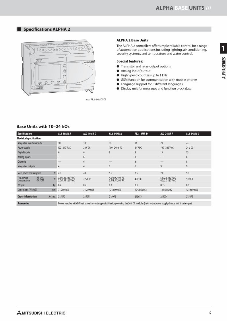
Base Units with 10–24 I/Os
AL2-10MR-D AL2-14MR-A AL2-14MR-D AL2-24MR-A AL2-24MR-D
Electrical specifications
Integrated inputs/outputs 10 10 14 14 24 24
Power supply 100–240 V AC 24 V DC 100–240 V AC 24 V DC 100–240 V AC 24 V DC
Digital inputs 6 6 8 8 15 15
Analog inputs — 6 — 8 — 8
Channels — 6 — 8 — 8
Integrated outputs 4 4 6 6 9 9
Max. power consumption W 4.9 4.0 5.5 7.5 7.0 9.0
Typ. powerconsumption
All I/OsON /OFF W 3.5/1.85 240 V AC
3.0/1.55 120 V AC 2.5/0.75 4.5/2.0 240 V AC3.5/1.5 120 V AC 4.0/1.0 5.5/2.5 240 V AC
4.5/2.0 120 V AC 5.0/1.0
Weight kg 0.2 0.2 0.3 0.3 0.35 0.3
Dimensions (WxHxD) mm 71.2x90x55 71.2x90x55 124.6x90x52 124.6x90x52 124.6x90x52 124.6x90x52
Order information Art. no. 215070 215071 215072 215073 215074 215075
Accessories Power supplies with DIN-rail or wall mounting possibilities for powering the 24 V DC modules (refer to the power supply chapter in this catalogue)
ALPHA 2 Base Units
The ALPHA 2 controllers offer simple reliable control for a rangeof automation applications including lighting, air conditioning,security systems, and temperature and water control.
Special features:� Transistor and relay output options� Analog input/output� High Speed counters up to 1 kHz� GSM function for communication with mobile phones� Language support for 8 different languages� Display unit for messages and function block data
ALPHA BASE UNITS ///

10 MITSUBISHI ELECTRIC
1
ALPH
ASE
RIES
Environmental Specifications
Programming Specifications
Ambient temperature Display: -10–55 °C, Hardware: -25–55 °C (storage temperature: -30–+70 °C)
Protection rating IP20
Noise immunity 1000 Vpp with noise generator; 1 µs at 30–100 Hz, tested by noise simulator
Dielectric withstand voltage 3750 V AC, >1 min. according to EN60730
Allowable relative humidity 35–85 % (no condensation)
Shock resistance Acc. to IEC 68-2-27: 147 m/s2 acceleration, 11 ms 3x3 directions
Vibration resistancedirect mounting Acc. to IEC-2-6: 19.6 m/s2 acceleration, 80 min. in each direction
DIN rail mounting Acc. to IEC-2-6: 9.8 m/s2 acceleration, 80 min. in each direction
Insulation resistance 500 V DC, 7 M� acc. to EN60730-1
Ambient conditions No corrosive gases, no dust
Certifications Please refer to pages 66–67 in this catalogue
Programming method Function block
Program capacity 200 function blocks or 5000 bytes
Program processing Cyclic processing of the stored program
Number of available instructions 38 different function blocks
Program storage Integrated EEPROM and optional additional EEPROM cassette
Data storage At voltage loss the current status of values, running time meters, and real-time data are stored for up to 20 days (at temperatures of 0 to 25 °C) throughintegrated capacitors
Processing time 1 ms + 20 �s/log. instruction (complex commands 500 �s/instruction)
Real-time clock Seconds, minutes, hours, day of week, month, year (4-digit); accuracy: 5 s/day; automatic summer and winter time toggling
Program protection Program and keys (3 levels)
Type
Type Relay
Switching voltage (max.) V 250 V AC, 30 V DC
Rated current10M, 14M: 8 A/point24M (001-004): 8 A/point24M (005-009): 2 A/point
Max. switchingload - inductive load 14M, 24M:249 VA, 250 V AC/373 VA, 250 V AC
24M: 93 VA, 125 V AC/93 VA, 250 V AC
Minimum load 10 mA, 5 V DC
Response time ms �10
Electrical Specifications
Power supply 24 V DC 100–240 V AC (50/60 Hz)
Inrush current at ON �7.0 A (at 24 V DC) �6.5 A (at 240 V AC)
Allowable momentary power failure time 5 ms 10 ms
Digital Inputs
Input voltage 24 V DC(+20 %/-15 %)
100–240 V AC(+10 %/-15 %), 50/60 Hz
Input current
The input current changesdepending on Source or Sink.For Sink:(AL2-10/14/24MR-D)= 5.5 mA, 24 V DCFor Source:(AL2-10/14MR-D)= 6.0 mA, 24VDC(AL2-24MR-D)= 5.5 mA, 24 V DC
I01–I080.13 mA/120 V AC*0.25 mA/240 V AC*I09–I150.15 mA/120 V AC*0.29 mA/240 V AC*
Response timeOFF�ON ms 10–20 35–85 ms, 120 V AC
25–55 ms, 240 V AC
ON�OFF ms 10–20 35–85 ms, 120 V AC50–130 ms, 240 V AC
Analog Inputs
Analog input range 0–500 —
Resolution 9 bit, (10 V/500) —
Conversion speed ms 8 —
Voltage 0–10 V DC —
Impedance k� 142 ±5 % —
Accuracy ±5 % (0.5 V DC) —
* Current leakage from the sensors connected to the inputs might provide enough current to turn thecontroller On. Do not use two wire sensors
/// GENERAL SPECIFICATIONS

11MITSUBISHI ELECTRIC
1
ALPH
ASE
RIES
Digital Extension Modules
There are 4 different extension modules available for the ALPHA 2, which allow the controllerto be extended through additional inputs or outputs. The modules are inserted directlyinto the ALPHA 2 and therefore do not take up any additional space.
The AL2-4EX has the additional feature that 2 inputs may be used as high-speed counterswith a counting frequency of 1 kHz.
All modules feature photocoupler insulation for all I/Os.
Note: The digital extension modules cannot be used with the AL2-10MR series.
MITSUBISHI
EO1
EO3 EO4
EO2
4EYR
RELAYOUTPUT
AL2-4EX AL2-4EYR AL2-4EYTInputsIntegrated inputs 4 4 — —Input voltage 220–240 V AC 24 V DC (+20 %, -15 %) — —
Input current 7.5 mA at 240 V AC (50 Hz),9.0 mA at 240 V AC (60 Hz) 5.4 mA ±1 mA at 24 V DC — —
OutputsIntegrated outputs — — 4 4Output type — — Relay TransistorSwitched voltage (max.) V — — 250 V AC, 30 V DC 5–24 V DCRated current A — — 2 A per output 1 A per output
Electrical specificationsPower Supply AC range (+10 %, -15 %) 220–240 V AC 24 V DC 100–240 V AC 24 V DC
Mechanical specificationsWeight kg 0.05 0.05 0.05 0.05Dimensions (WxHxD) mm 53.1x90x24.5 53.1x90x24.5 53.1x90x24.5 53.1x90x24.5
Order information Art. no. 142522 142521 142523 142524
POWER24V DC
MITSUBISHI
POWER
V1+
SLD
+
K-type Thermocouple -50~450°CAL2-2TC-ADP
L1+
-
L1-
V2+
L2-
V1-
L2+
V2-
SLD
OUTPUTCH1 CH2
0~10V
450°C 450°CCH1 CH2
-50°C -50°CLine Line
CH1 CH2
POWER24V DC
MITSUBISHI
POWER
V1+
I1-
+
PT100 -50~200°CAL2-2PT-ADP
L1+
-
L1-
V2+
L2-
V1-
L2+
V2-
I2-
OUTPUTCH1 CH2
0~10V
200°C 200°CCH1 CH2
-50°C -50°CLine Line
CH1 CH2
MITSUBISHI
2DA
+ V1+ I1+ VI1--
V2+ I2+ VI2-
POWER24V DC
ANALOGOUTPUT
ANALOGOUTPUT
Analog Extension Modules
The analog extension modules significantly increase the range of applications for theALPHA 2. With these modules it is possible to output voltage or current signals or tomeasure temperatures.
Three different analog extension modules are available:� The AL2-2DA offers two additional analog outputs for the ALPHA 2 and converts a
digital input value into a voltage or a current. This module is inserted directly into theALPHA 2.Note: the AL2-2DA cannot be used with the AL2-10MR series.
� The AL2-2PT-ADP connects an external PT100 sensor to convert temperature readingsinto analog signals (0–10 V).
� The AL2-2TC-ADP connects thermocouple sensors (K type) to convert temperaturereadings into analog signals (0–10 V).
AL2-2PT-ADP AL2-2TC-ADPAnalog inputsIntegrated inputs — 2 2
Connectable temperature sensors — PT100 sensorTemp. coefficient 3.850 ppm/°C (IEC 751)
Thermocouple (K type), isolated type(IEC 584-1 1977, IEC 584-2 1982)
Compensated range — -50–+200 °C -50–+450 °CAnalog outputsIntegrated outputs 2 — —
Analog outputrange
voltage 0–10 V DC (5 k� 1 M�) — —current 4–20 mA (max. 500 �) — —
Electrical specificationsNumber of channels 2 2 2Power Supply 24 V DC (-15–+10 %), 70 mA 24 V DC (-15–+20 %), 1 W 24 V DC (-15–+20 %), 1 W
Mechanical specificationsWeight kg 0.05 0.07 0.07Dimensions (WxHxD) mm 53.1x90x24.5 35.5x90x32.5 35.5x90x32.5
Order information Art. no. 151235 151238 151239
Note: EI1 and EI2 of the AL2-4EX can be used as high-speed counter inputs. In each case the response time for the high-speed counter inputs will be 0.5 ms or less.The AL2-4EX-A2, AL2-4EX, AL2-4EYR and AL2-4EYT modules can not be used with the AL2-10MR series.
EXTENSION MODULES ///

12 MITSUBISHI ELECTRIC
1
ALPH
ASE
RIES
AS-Interface Module AL2-ASI-BD
The Actuator Sensor Interface module AL2-ASI-BD in combination with an ALPHA 2 con-troller facilitates the data communications via an AS-Interface system. The AL2-ASI-BD isattached to an ALPHA 2 series module and forms a slave unit. Up to 4 inputs and 4 out-puts can be exchanged with the AS-Interface master.
The addresses of the slave devices in the AS-Interface are assigned either automaticallyvia the master in the network or via a programming device (software).
The maximum communication distance is 100 m without a repeater. If 2 repeaters areused, the distance is extended to up to 300 m.
For the AS-Interface a separate power supply is required. The communication signal issuperimposed on the power supply of the AS-Interface bus.
Note: The AL2-ASI-BD cannot be used with the AL2-10MR series.
Module type Slave moduleNumber of I/O points 4 inputs, 4 outputsExternal power supply 30.5 V DC (AS-Interface power supply)External current consumption mA Max. 40Communications protocol AS-Interface standardWeight kg 0.05Dimensions (WxHxD) mm 53.1x90x24.5
Order information Art. no. 142525
ASI+ ASI+ASI- ASI-
AL2-E
EP
RO
MM
AD
EIN
JA
PA
N
Memory Cassette AL2-EEPROM-2 Memory Media
With the AL2-EEPROM-2 memory cassettes, a new program can be transferred to theALPHA 2 controller’s internal system memory from the cassette, or the program of theinternal system memory can be saved to the cassette.
If the memory cassette is used, a certain program can be run temporarily by simplyplugging the external memory module onto the ALPHA 2.
After removing the memory cassette, the former program in the internal memorybecomes active again.
The memory cassette AL2-EEPROM-2 is not a memory expansion device, but a mediumfor data exchange.
Memory type EEPROMApplication ALPHA 2Memory capacity 5,000 bytesFunction blocks Max. 200Dimensions (WxHxD) mm 10x45x25
Order information Art. no. 142526
AL2-GSM-CABLOT .24MITSUBISHI ELECTRIC
Interface Cable AL-232CAB
The AL-232CAB is an RS232C interface cable. It connects the ALPHA 2 controller to apersonal computer running the programming software for the ALPHA 2 controller.
The cable ensures a galvanic isolation between the ALPHA 2 controller and the personalcomputer. The cable AL-232CAB can not be used for any other connection.
GSM Cable AL2-GSM-CAB
The GSM AL2-GSM-CAB is an RS232C interface cable and it is used to connect theALPHA 2 controller to a normal or GSM modem, a personal computer or other serialdevices. It can transfer SMS data to a GSM modem for onward transmission to mobile tele-phones or e-mail addresses. It also permits remote monitoring and remote maintenance.
Note: The above cables cannot be used with the AL2-10MR series.
Connector 9-pin D-SUB female connector 9-pin D-SUB male connectorApplication ALPHA 2 <-> PC ALPHA 2 <-> PC, modemLength m 2.5 1.5
Order information Art. no. 87674 142528AL2-GSM-CAB
AL-232CAB
/// EXTENSION MODULES AND ACCESSORIES

13MITSUBISHI ELECTRIC
2
FXBA
SEUN
ITS
0 1 2 34 5 6 7
0 1 2 34 5
IN
OUT
POWER
FX -14MR1S
RUNERROR
X7X5X3X1S/S X6X4X2X0NL100-240
VAC
14MR-ES/ULY4Y2Y1Y0
COM0COM1COM2 Y3 Y524V
0V
MITSUBISHI
Connection of thepower supply Terminals for
digital inputs
LEDs for indicating theoperating status
Adapter interface
Protective cover
RUN/STOP switch
Terminal cover
Service voltagesource
2 analog potentiometers
LEDs for indicatingthe input status
Fixing hole
Slot for adapter
Connection forprogramming units
Housing cover
LEDs for indicatingthe output status
Terminals fordigital outputs
Description of the Unit Components
The MELSEC FX1S Series
Square pulse output(this applies only to transistor units.)
Two high speed pulseoutputs for frequencies up to100 kHz for outputtingand controlling stepping motors
High-speed inputs for fast countingtasks with counting frequencies ofup to 60 kHz and interrupt processingcapabilities
All units feature two analogpotentiometer for setpointvalue entry and an integratedRUN/STOP switch.
Your PLC programs are stored in a main-tenance-free EEPROM user memorywith a capacity of 2,000 program steps,so there is no need for a backup batteryto protect against power failures.
Flexible installation with theintegrated DIN rail adapter andscrew fastening holes for mount-ing on flat surfaces
Integrated serial RS422interface for direct commu-nication with computers
The internal service powersupply unit for 24 V DC hasa capacity of 400 mA.
Note: service power supplyis only available for AC PowerSupply types.
Password access protectionfacility for effective protectionof your intellectual property.
Integration of interface, exten-sion, and functions adapters fordirect installation in the base unit
MITSUBISHI
0 1 2 3
4 5 6 7
0 1 2 3
4 5
POWER
RUNERROR
FX1S-14MR
IN
OUT
MELSEC
Integrated real-timeclock with year, month,day and time
BASE UNITS FX1S SERIES ///

14 MITSUBISHI ELECTRIC
2
FXBA
SEUN
ITS
FX1S-10MR-ES/UL
FX1S-10MT-DSS
FX1S-14MR-DS
FX1S-14MR-ES/UL
FX1S-14MT-DSS
Max. number inputs/outputs 10 10 10 14 14 14Power supply 24 V DC 100–240 V AC 24 V DC 24 V DC 100–240 V AC 24 V DCIntegrated inputs 6 6 6 8 8 8Integrated outputs 4 4 4 6 6 6
Output type Relay Relay Transistor(source) Relay Relay Transistor
(source)
Power consumption W 6 19 6 6.5 19 6.5Weight kg 0.22 0.3 0.22 0.22 0.3 0.22Dimensions (WxHxD) mm 60x90x49 60x90x75 60x90x49 60x90x49 60x90x75 60x90x49
Order information Art. no. 141240 141243 141246 141247 141248 141249
FX1S-20MR-ES/UL
FX1S-20MT-DSS
FX1S-30MR-DS
FX1S-30MR-ES/UL
FX1S-30MT-DSS
Max. number inputs/outputs 20 20 20 30 30 30Power supply 24 V DC 100–240 V AC 24 V DC 24 V DC 100–240 V AC 24 V DCIntegrated inputs 12 12 12 16 16 16Integrated outputs 8 8 8 14 14 14
Output type Relay Relay Transistor(source) Relay Relay Transistor
(source)
Power consumption W 7 20 7 8 21 8Weight kg 0.3 0.4 0.3 0.35 0.45 0.35Dimensions (WxHxD) mm 75x90x49 75x90x75 75x90x49 100x90x49 100x90x75 100x90x49
Order information Art. no. 141251 141252 141254 141255 141256 141257
0 1 2 34 5 6 7
0 1 2 34 5
IN
OUT
POWER
FX -14MR1S
RUNERROR
MITSUBISHI
X7X5X3X1S/S X6X4X2X0NL100-240
VAC
14MR-ES/ULY4Y2Y1Y0
COM0COM1COM2 Y3 Y524V
0V
Base Units FX1S
The FX1S series base units are available with 10 to 30 input/outputpoints.
It is possible to choose between relay and transistor output type.
Note: Versions with UL certification are available on request.
Special Features:� Integrated power supply (AC or DC powered)� Maintenance-free EEPROM memory� Ample memory capacity (2000 steps) and device ranges� High-speed operations� Incorporated positioning control� Integrated real-time clock� System upgrades by exchangeable interface and I/O adapter
boards for direct fitting into the base unit� LEDs for indicating the input and output status� Standard programming unit interface� User-friendly programming systems, including IEC 61131.3
(EN 61131.3)-compatible programming software, HMIs andhand-held programming units
� Base Units � FX1S� FX1N� FX3G� FX3U� FX3UC
Base Units with 10–14 I/Os
Base Units with 20–30 I/Os
/// BASE UNITS FX1S SERIES

15MITSUBISHI ELECTRIC
2
FXBA
SEUN
ITS
Type Transistormodules
Switching voltage (max.) V <250 V AC, <30 V DC 5–30 V DC
Max. outputcurrent
- per output A 2 0.5
- per group* A 8 0.8
Max. switchingcurrent
- inductive load 80 VA 12 W
- lamp load W 100 1.2
Response time ms 10 0.2
Life of contacts (switching times)** 3,000,000 at 20 VA; 1,000,000 at 35 VA;200,000 at 80 VA
* The limitation applies only per reference terminal for each group, 1 and 4 outputs for relays andtransistors. Please observe the terminal assignments for the group identification.
** Not guaranteed by Mitsubishi Electric.
Power supply 24 V DC (+10 %/-15 %) 100–240 V AC (+10 %/-15 %),50/60 Hz (±10 %)
Inrush current at ON 10 A/0.1 ms (at 24 V DC) 15 A/5 ms (at 100 V AC);25 A/5 ms (at 200 V AC)
Allowable momentary powerfailure time 5 ms 10 ms
Primary power supply 24 V DC, 400 mA
External power supply (24 V DC) — 400 mA
Ambient temperature 0–55 °C (storage temperature: -20–+70 °C)
Protection IP10
Noise durability 1000 Vpp with noise generator; 1 µs at 30–100 Hz
Dielectric withstand voltage 1,500 V AC, 1 min. (500 V AC for direct voltage modules)
Ambient relative humidity 35–85 % (non-condensing)
Shock resistance Acc. to IEC/EN 68-2-27: 15G (3 times each in 3 directions for 11 ms)
Vibration resistance Acc. to IEC/EN 68-2-6: 1G (resistance to vibrations from 57–150 Hz for 80 minutes along all 3 axes); 0.5G for DIN rail mounting
Insulation resistance 500 V DC, 5 M�
Ground Class D: Grounding resistance 100 � or less
Fuse rating AC models: 250 V 1.0 A; DC models: 0.8 A
Environment Avoid environments containing corrosive gases, install in a dust-free location.
Certifications Please refer to pages 66–67 in this catalogue
Programming Specifications
Program data
Program memory 2.000 steps EEPROM (internal)
Program execution Periodical execution of the stored program
Program protection Password protection with 3 protection levels. Note: Protection levels may only be changed with FX-10P/FX-20P/FX-30P.
Number of instructions 27 sequence instructions, 2 step ladder instructions, 85 applied instructions
Cycle period 0.55–0.7 µs/logical instruction
Operands
Internal relays 512 total, with 384 general (M0–M383) and 128 latched (M384–M511)
Special relays 256 (M8000–M8255)
State relays 128
Timers 64 (max. 63 timers, partially switchable to 100 ms and 10 ms)
External setpoint entry via potentiometer 2 potentiometers
Counter 32 (16 bit), C0–C31
High-speed counter inputs 1 phase, 6 points max: 60kHz/2 points, 10kHz/4 points ; 2 phase, 2 points max: 30kHz/1 point, 5kHz/1 point
Data register 256 subtotal (128 general (D0–D127) and 128 latched (D128–D255))
Index register 16
Special register 256 (16 bit), D8000–D8255
Pointer 64, P0–P63
Nesting operands 8, N0–N7
Interrupt inputs 6
Constants 16 bits: K: -32768 to +32767, hex: 0–FFFF32 bits: K: -2147483648 to +2147483647, hex: 0–FFFF FFFF
Environmental Specifications
Electrical Specifications
� Base Units � FX1S� FX1N� FX3G� FX3U� FX3UC
BASE UNITS FX1S SERIES ///

16 MITSUBISHI ELECTRIC
2
FXBA
SEUN
ITS
The MELSEC FX1N Series
The base units can be expandedfor up to 128 inputs/outputs withdifferent extension units.
High-speed inputs for fastcounting tasks with countingfrequencies of up to 60 kHz andinterrupt processingcapabilities
Integrated RUN/STOP switch andtwo analog potentiometers forsetpoint value entry.
The base units have integrated,maintenance-free EEPROMuser memory for up to 8,000PLC program steps, so thereis no need for a backup battery toprotect against power failure.You can also configure passwordprotection to prevent unautho-rized access to your programs.
Square pulse output(This only applies for transistor units.)
Two integrated high-speed pulseoutputs for frequencies up to100 kHz for outputting pulsesignals and controlling steppingmotors
External EEPROM memorycassettes for PLC program storage
Integration of
for direct installa-tion in the base unit
01
23
45
67
10 11 12 13
14 15
01
23
45
67
10 11
POWER
RUNERROR
FX1N-24MR
IN
OUT
MITSUBISHI
MELSEC
Integrated real-timeclock with year, month,day and time
Protective cover
Terminal cover
Terminals fordigital outputs
Terminals forservice voltage source
Connection forprogramming units
Terminal cover
0 1 2 34 5 6 78 9 10 1112 13 14 15
0 1 2 34 5 6 710 11
IN
OUT
POWER
FX -24MR1N
RUNERROR
100-240VAC
X7 X11 X13 X15X5X3X1S/S X6 X10 X12 X14
X4X2X0NL
24MR-ES/ULY10Y6Y5Y3
COM3 Y4 COM4 Y7 Y11COM2COM1COM024+
Y2Y1Y00V
MITSUBISHI
RUN/STOP switch Extension bus
Connection of thepower supply
LEDs for indicating theoperating status
LEDs for indicatingthe input status
Protective cover
Lid
Slot for memory cassettes,displays and ADPs.
2 analog potentiometers
Terminals fordigital inputs
LEDs for indicatingthe output status
Housing cover
Fixing hole
Description of the Unit Components
/// BASE UNITS FX1N SERIES
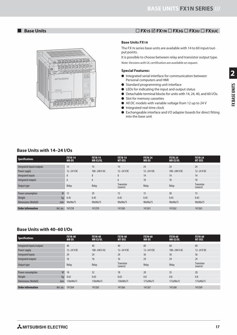
17MITSUBISHI ELECTRIC
2
FXBA
SEUN
ITS
� Base Units � FX1S� FX1N� FX3G� FX3U� FX3UC
Base Units FX1N
The FX1N series base units are available with 14 to 60 input/out-put points.
It is possible to choose between relay and transistor output type.
Note: Versions with UL certification are available on request.
Special Features:� Integrated serial interface for communication between
Personal computers and HMI� Standard programming unit interface� LEDs for indicating the input and output status� Detachable terminal blocks for units with 14, 24, 40, and 60 I/Os.� Slot for memory cassettes� All DC models with variable voltage from 12 up to 24 V� Integrated real-time clock� Exchangeable interface and I/O adapter boards for direct fitting
into the base unit
MITSUBISHI
0 1 2 34 5 6 78 9 10 1112 13 14 15
0 1 2 34 5 6 710 11
IN
OUT
POWER
FX -24MR1N
RUNERROR
100-240VAC
X7 X11 X13 X15X5X3X1S/S X6 X10 X12 X14
X4X2X0NL
24MR-ES/ULY10Y6Y5Y3
COM3 Y4 COM4 Y7 Y11COM2COM1COM024+
Y2Y1Y00V
Specifications FX1N-14MR-DS
FX1N-14MR-ES/UL
FX1N-14MT-DSS
FX1N-24MR-DS
FX1N-24MR-ES/UL
FX1N-24MT-DSS
Integrated inputs/outputs 14 14 14 24 24 24Power supply 12–24 V DC 100–240 V AC 12–24 V DC 12–24 V DC 100–240 V DC 12–24 V DCIntegrated inputs 8 8 8 14 14 14Integrated outputs 6 6 6 10 10 10
Output type Relay Relay Transistor(source) Relay Relay Transistor
(source)
Power consumption W 13 29 13 15 30 15Weight kg 0.45 0.45 0.45 0.45 0.45 0.45Dimensions (WxHxD) mm 90x90x75 90x90x75 90x90x75 90x90x75 90x90x75 90x90x75
Order information Art. no. 141258 141259 141260 141261 141262 141263
Base Units with 14–24 I/Os
Base Units with 40–60 I/Os
Specifications FX1N-40MR-DS
FX1N-40MR-ES/UL
FX1N-40MT-DSS
FX1N-60MR-DS
FX1N-60MR-ES/UL
FX1N-60MT-DSS
Integrated inputs/outputs 40 40 40 60 60 60Power supply 12–24 V DC 100–240 V AC 12–24 V DC 12–24 V DC 100–240 V AC 12–24 V DCIntegrated inputs 24 24 24 36 36 36Integrated outputs 16 16 16 24 24 24
Output type Relay Relay Transistor(source) Relay Relay Transistor
(source)
Power consumption W 18 32 18 20 35 20Weight kg 0.65 0.65 0.65 0.8 0.8 0.8Dimensions (WxHxD) mm 130x90x75 130x90x75 130x90x75 175x90x75 175x90x75 175x90x75
Order information Art. no. 141264 141265 141266 141267 141268 141269
BASE UNITS FX1N SERIES ///

18 MITSUBISHI ELECTRIC
2
FXBA
SEUN
ITS
� Base Units � FX1S� FX1N� FX3G� FX3U� FX3UC
Environmental Specifications
Ambient temperature 0–55 °C (storage temperature: -20–+70 °C)
Protection IP10
Noise durability 1000 Vpp with noise generator; 1 µs at 30–100 Hz
Dielectric withstand voltage 1,500 V AC, 1 min. (500 V AC for direct voltage modules)
Ambient relative humidity 35–85 % (non-condensing)
Shock resistance Acc. to IEC 68-2-27: 15G (3 times each in 3 directions for 11 ms)
Vibration resistance Acc. to IEC 68-2-6: 1G (resistance to vibrations from 57–150 Hz for 80 minutes along all 3 axes); 0.5G for DIN rail mounting
Insulation resistance 500 V DC, 5 M�
Ground Class D: Grounding resistance 100 � or less
Fuse rating AC units: From FX1N-14M� to FX1N-24M�: 250 V AC 1.0 A; From FX1N-40M� to FX1N-60M�: 250 V AC 3.15 A/DC units: 125 V DC 3.15 A
Environment Avoid environments containing corrosive gases, install in a dust-free location.
Certifications Please refer to pages 66–67 in this catalogue
Program data
I/O points (addresses) 128 (+4 optional)
Address range Max.128 inputs X0–X177,max. 128 outputs Y0–Y177
Program memory 8,000 steps EEPROM (internal), exchangeableEEPROM for easy program exchange
Cycle period 0.55–0.7 µs /logical instruction
Number of instructions 27 sequence instructions, 2 step ladder instructions,89 applied instructions
Programming language Step ladder, instruction list, SFC
Program execution Cyclical execution, refresh mode processing
Program protection Password protection with 3 protection levels*
* Protection levels may only be changed with FX-10P/FX-20P/FX-30P.
Operands
Internal relays 1,536
Special relays 256
Step ladder 1,000
Timer 256
Ext. preset value via potentiometer 2
Counter 235
High-speed counter 1 phase, 6 points max: 60kHz/2 points, 10kHz/4 points;2 phase, 2 points max: 30kHz/1 point, 5kHz/1 point
Real-time clock Year, month, day, hour, minute, second, weekday
Data register 8,000
File register Max. 7,000 (parameter editable),Total registers = 8,000
Index register 16
Special register 256
Pointer 128
Nestings 8
Interrupt inputs 6
Constants 16 bits: K: -32768 to +32767, hex: 0–FFFF; 32 bits:K: 2147483648 to +2147483647, hex: 0–FFFF FFFF
Programming Specifications
Type Transistormodules
Switching voltage (max.) V <240 V AC, <30 V DC 5–30 V DC
Max. outputcurrent
- per output A 2 0.5
- per group A 8 0.8
Max. switchingcurrent - inductive load 80 VA 12 W
Response time ms 10 <0.2 (Y0, Y1 <5 µs)
Life of contacts (switching times)* 3,000,000 at 20 VA; 1,000,000 at 35 VA;200,000 at 80 VA
* Not guaranteed by Mitsubishi Electric.
Power supply 12–24 V DC (+20 %/-15 %) 100–240 V AC (+10 %/-15 %),50/60 Hz (±10 %)
Inrush current at ON 25 A/1 ms (at 24 V DC);22 A/0.3 ms (at 12 V DC)
30 A/5 ms (at 100 V AC);50 A/5 ms (at 200 V AC)
Allowable momentary powerfailure time 5 ms 10 ms
Primary power supply 24 V DC, 400 mA
External power supply (24 V DC) — 400 mA
Electrical Specifications
/// BASE UNITS FX1N SERIES

19MITSUBISHI ELECTRIC
2
FXBA
SEUN
ITS
The base units can be expandedto provide configurations with upto 256 inputs and outputs withmodular and compact extensionunits.
Integrated high-speed counter inputs forprocessing fast input signals. For example,you can configure two 60 kHz countersand four 10 kHz counters.
Interrupt processing is also handledvia the inputs.
Two integrated serial interfacesfor direct communication withcomputers.
Two integrated pulse outputs for frequenciesfrom 2 to 100,000 Hz for controlling steppingmotors and outputting pulse-width modu-lated signals.
RAM/EEPROM memory for up to32,000 PLC program steps givesyou plenty of reserve, even forbig, complex applications.
An integrated RUN/STOP switchis available.
Integrated real-timeclock with year, month,day and time
Add-in function boards can be installedin the PLC to provide a second RS485/RS422/RS232 communicationsinterface for programming ornetwork configurations.
Analog function boards for inputand output and a function board with8 analog potentiometers are alsoavailable as add-in.
The MELSEC FX3G Series
Memory cassette, displaymodule, and expansion
board connector
Option battery holder
Terminal protector
Flip cover for programmingport, potentiometer and
Run/Stop switch
Expansion bus connectorcover
Terminal protector
Output indicator LEDs
Top cover
Protective cover
2 analog potentiometers
Programming port: RS-422
Input indicator LEDs
Programming port: USB
Input terminals
Terminal cover
Description of the Unit Components
BASE UNITS FX3G SERIES ///
RUN/STOP switch Operation status indicatorLEDs
Output terminals
Terminal cover
Connection possibility forspecial function adaptermodules

20 MITSUBISHI ELECTRIC
2
FXBA
SEUN
ITS
Base Units FX3G
The FX3G series base units are available with 14 to 60 input/outputpoints .
It is possible to choose between relay and transistor output types.
Special features:� Integrated USB interface for communication between PLCs and PC� Integrated serial interface for communication between PCs and HMI� LEDs for indicating the input and output status� Detachable terminal blocks for all units� Slot for memory cassettes� Integrated real-time clock� Integrated positioning control� Exchangeable interface and extension adapters for direct
mounting into a base unit� Expandable with digital I/O modules, special function modules
and ADP modules� User-friendly programming systems, including IEC 1131.3
(EN 61131.3) compatible programming software, HMIs andhand-held programming units
� Base Units � FX1S� FX1N� FX3G� FX3U� FX3UC
/// BASE UNITS FX3G SERIES
Base Units with 14–24 I/Os
Specifications FX3G-14MR/ES
FX3G-14MT/ESS
FX3G-14MR/DS
FX3G-14MT/DSS
FX3G-24MR/ES
FX3G-24MT/ESS
FX3G-24MR/DS
FX3G-24MT/DSS
Integrated inputs/outputs 14 14 14 14 24 24 24 24Power supply 100–240 V AC 100–240 V AC 24 V DC 24 V DC 100–240 V AC 100–240 V AC 24 V DC 24 V DCIntegrated inputs 8 8 8 8 14 14 14 14Integrated outputs 6 6 6 6 10 10 10 10
Output type Relay Transistor(source)* Relay Transistor
(source)* Relay Transistor(source)* Relay Transistor
(source)*Power consumption W 31 31 19 19 32 32 21 21Weight kg 0.50 0.50 0,50 0,50 0.55 0.55 0,55 0,55Dimensions (WxHxD) mm 90x90x86 90x90x86 90x90x86 90x90x86 90x90x86 90x90x86 90x90x86 90x90x86
Order information Art. no. 231466 231470 231474 231478 231467 231471 231475 231479
* Sink type transistor output units on request.
Specifications FX3G-40MR/ES
FX3G-40MT/ESS
FX3G-40MR/DS
FX3G-40MT/DSS
FX3G-60MR/ES
FX3G-60MT/ESS
FX3G-60MR/DS
FX3G-60MT/DSS
Integrated inputs/outputs 40 40 40 40 60 60 60 60Power supply 100–240 V AC 100–240 V AC 24 V DC 24 V DC 100–240 V AC 100–240 V AC 24 V DC 24 V DCIntegrated inputs 24 24 24 24 36 36 36 36Integrated outputs 16 16 16 16 24 24 24 24
Output type Relay Transistor(source)* Relay Transistor
(source)* Relay Transistor(source)* Relay Transistor
(source)*Power consumption W 37 37 25 25 40 40 29 29Weight kg 0.70 0.70 0,70 0,70 0.85 0.85 0,85 0,85Dimensions (WxHxD) mm 130x90x86 130x90x86 130x90x86 130x90x86 175x90x86 175x90x86 175x90x86 175x90x86
Order information Art. no. 231468 231472 231476 231480 231469 231473 231477 231481
* Sink type transistor output units on request.
Base Units with 40–60 I/Os

21MITSUBISHI ELECTRIC
2
FXBA
SEUN
ITS
� Base Units � FX1S� FX1N� FX3G� FX3U� FX3UC
Environmental Specifications
Ambient temperature 0–55 °C (storage temperature: -25–+75 °C)
Protection IP10
Noise durability 1000 Vpp with noise generator; 1 µs at 30–100 Hz
Dielectric withstand voltage 1500 V AC, 1 min.
Ambient relative humidity 5–95 % (non-condensing)
Shock resistance 147m/s2 Acceleration, Action time: 11ms, 3 times by half-sine pulse in each direction X, Y, and Z
Vibration resistance Acc. to IEC 68-2-6: 1 g (resistance to vibrations from 57–150 Hz for 80 minutes along all 3 axes); 0.5 g for DIN rail mounting
Insulation resistance 500 V DC, 5 M�
Ground Class D: Grounding resistance 100 � or less
Fuse For FX3G-14M� and FX3G-24M�: 250 V 1 A; For FX3G-40M� and FX3G-60M�: 250 V 3.15 A
Environment Avoid environments containing corrosive gases, install in a dust-free location.
Certifications Please refer to pages 66–67 in this catalogue
Program data
I/O points (addresses) 256 total (combined local and CC-Link remote I/O)
Address range Max. 128 direct addressing and max. 128 remote I/O
Program memory 32,000 steps EEPROM (internal),exchangeable EEPROM memory cassette
Cycle period 0.21 µs or 0.42 µs/contact instruction
Number of instructions29 sequence instructions,2 step ladder instructions,123 applied instructions
Programming language Step ladder, instruction list, SFC
Program execution Cyclical execution, refresh mode processing
Program protection 2 different keywords,maximum password length 16 characters
Operands
Internal relays 7680
Special relays 512
Step ladder 4096
Timer 320
Ext. preset value via potentiometer 2
Counter 235
High-speed counter 6 single phase inputs (max. 60 kHz),3 double phase inputs (max. 30 kHz)
Real-time clock Year, month, day, hour, minute, second, weekday
Data register 8.000
File register 24,000 (ER0~R23999) internal/optional memory
Index register 16
Special register 512 (D8000-D8511)
Pointer 2,048
Nestings 8
Interrupt inputs 6
Constants16 bits: K: -32,768 to +32,767; hex: 0–FFFF32 bits: K: 2,147,483,648 to +2,147,483,647;hex: 0–FFFF FFFF
Programming Specifications
Transistormodules
Switching voltage (max.) V <240 V AC, <30 V DC 5–30 V DC
Max. outputcurrent
- per output A 2 0.5
- per group* A 8 0.8
Max. switchingcurrent - inductive load 80 VA 12 W
Response time ms 10 <0.2(<5 µs for Y0,Y1) �
Life of contacts (switching times) � 3,000,000 at 20 VA; 1,000,000 at 35 VA;200,000 at 80 VA
� The 40 and 60 I/O points main units supports 5 µs for Y2. � Not guaranteed by Mitsubishi Electric.* This limitation applies only per reference terminal for each group, 4 and 8 outputs for relays and
2 and 4 outputs for transistors. Please observe the terminal assignments for the group identification.
Power supply 100–240 V AC (+10 %/-15 %), 50/60 Hz
Inrush current at ON 30 A/<5 ms (at 100 V AC);50 A/<5 ms (at 200 V AC)
Allowable momentary powerfailure time 10 ms
Primary power supply —
External power supply (24 V DC) 400 mA
Electrical Specifications
BASE UNITS FX3G SERIES ///

22 MITSUBISHI ELECTRIC
2
FXBA
SEUN
ITS
The MELSEC FX3U Series
Description of the Unit Components
The base units can be expandedto provide configurations with upto 384 inputs and outputs withcompact extension units(total of 384 only by using mainunit I/Os, extension unit I/Os andremote I/Os).
Integrated high-speed counter for processingfast input signals. For example, you can configure six100 kHz counters and two 10 kHz counters.
Interrupt processing is also handled via the inputs.
An integrated RUN/STOPswitch is available.
Three integrated pulse outputs for frequenciesup to 100 kHz with deceleration and accelerationramps for controlling stepping motors and output-ting pulse-width modulated signals.
RAM/EEPROM memory for up to64,000 PLC program steps givesyou plenty of reserve, even forbig, complex applications.
Integrated serial interfacefor direct communication withcomputers
Integrated real-timeclock with year, month,days and time
Add-in function boards can be installedin the PLC to provide a second RS485 /RS422 / RS232/USB communicationsinterface for programming ornetwork configurations.
Battery cover
Installation place forFX3U-7DM
Periphal deviceconnecting connector
LEDs for indicatingthe output status
Expansion boarddummy cover
LEDs for indicating theoperating status
RUN/STOP switch
Extension device connect-ing connector cover
LEDs for indicatingthe input status
Top cover with Model name(used, if FX3U-7DM
is not installed)
Battery
Protective cover
Output terminals
Terminal block cover
Protective cover
Input terminals
Terminal block cover
/// BASE UNITS FX3U SERIES
Connection possibility forspecial function adapter modules

23MITSUBISHI ELECTRIC
2
FXBA
SEUN
ITS
Base Units FX3U
The FX3U series base units are available with 16, 32, 48, 64, 80 or128 input/output points expandable to 384 points.
It is possible to choose between relay and transistor output type.
Note: Additional special versions are available on request.
Special Features:� Integrated serial interface for communication between PCs and HMI� Integrated positioning control� Exchangeable interface modules for direct mounting into a
base unit� LEDs for indicating the input and output status� Slot for memory cassettes� Integrated real-time clock� Expandable with digital I/O modules, special function modules
and ADP modules� User-friendly programming systems, including IEC 1131.3
(EN 61131.3) compatible programming software, HMIs andhand-held programming units
� Base Units � FX1S� FX1N� FX3G� FX3U� FX3UC
FX3U-16MR/ES
FX3U-16MT/DSS
FX3U-16MT/ESS
Integrated inputs/outputs 16 16 16 16Power supply 24 V DC 100–240 V AC 24 V DC 100–240 V ACIntegrated inputs 8 8 8 8Integrated outputs 8 8 8 8
Output type Relay Relay Transistor(source type)
Transistor(source type)
Power consumption 25 W 30 VA 25 W 30 VAWeight kg 0.6 0.6 0.6 0.6Dimensions (WxHxD) mm 130x90x86 130x90x86 130x90x86 130x90x86
Order information Art. no. 231498 231486 231503 231492
Base Units with 16 I/Os
Base Units with 32 I/OsFX3U-32MR/ES
FX3U-32MT/DSS
FX3U-32MT/ESS
Integrated inputs/outputs 32 32 32 32Power supply 24 V DC 100–240 V AC 24 V DC 100–240 V ACIntegrated inputs 16 16 16 16Integrated outputs 16 16 16 16
Output type Relay Relay Transistor(source type)
Transistor(source type)
Power consumption 30 W 35 VA 30 W 35 VAWeight kg 0.65 0.65 0.65 0.65Dimensions (WxHxD) mm 150x90x86 150x90x86 150x90x86 150x90x86
Order information Art. no. 231499 231487 231504 231493
BASE UNITS FX3U SERIES ///

24 MITSUBISHI ELECTRIC
2
FXBA
SEUN
ITS
FX3U-48MT/ESS
FX3U-48MT/DSS
Integrated inputs/outputs 48 48 48 48Power supply 24 V DC 100–240 V AC 100–240 V AC 24 V DCIntegrated inputs 24 24 24 24Integrated outputs 24 24 24 24
Output type Relay Relay Transistor(source type)
Transistor(source type)
Power consumption 35 W 40 VA 40 VA 35 WWeight kg 0.85 0.85 0.85 0.85Dimensions (WxHxD) mm 182x90x86 182x90x86 182x90x86 182x90x86
Order information Art. no. 231500 231488 231494 231505
Base Units with 48 I/Os
Base Units with 64 I/OsFX3U-64MR/ES
FX3U-64MT/ESS
FX3U-64MT/DSS
Integrated inputs/outputs 64 64 64 64Power supply 24 V DC 100–240 V AC 100–240 V AC 24 V DCIntegrated inputs 32 32 32 32Integrated outputs 32 32 32 32
Output type Relay Relay Transistor(source type)
Transistor(source type)
Power consumption 40 W 45 VA 45 VA 40 WWeight kg 1.0 1.0 1.0 1.0Dimensions (WxHxD) mm 220x90x86 220x90x86 220x90x86 220x90x86
Order information Art. no. 231501 231489 231495 231506
FX3U-80MR/ES
FX3U-80MT/DSS
FX3U-80MT/ESS
FX3U-128MR/ES
FX3U-128MT/ESS
Integrated inputs/outputs 80 80 80 80 128 128Power supply 24 V DC 100–240 V AC 24 V DC 100–240 V AC 100–240 V AC 100–240 V ACIntegrated inputs 40 40 40 40 64 64Integrated outputs 40 40 40 40 64 64
Output type Relay Relay Transistor(source type)
Transistor(source type) Relay Transistor
(source type)
Power consumption 45 W 50 VA 45 W 50 VA 65 VA 65 VAWeight kg 1.20 1.20 1.20 1.20 1.80 1.80Dimensions (WxHxD) mm 285x90x86 285x90x86 285x90x86 285x90x86 350x90x86 350x90x86
Order information Art. no. 231502 231490 231507 231496 231491 231497
Base Units with 80–128 I/Os
/// BASE UNITS FX3U SERIES

25MITSUBISHI ELECTRIC
2
FXBA
SEUN
ITS
� Base Units � FX1S� FX1N� FX3G� FX3U� FX3UC
Environmental Specifications
Programming Specifications
Electrical Specifications
Ambient temperature 0–55 °C (storage temperature: -25–+75 °C)
Protection IP10
Noise durability 1000 Vpp with noise generator; 1 µs at 30–100 Hz
Dielectric withstand voltage AC PSU: 1500 V AC, 1 min./DC PSU: 500 V AC, 1 min.
Ambient relative humidity 5–95 % (non-condensing)
Shock resistance Acc. to IEC 68-2-27: 15G (3 times each in 3 directions for 11 ms)
Vibration resistance Acc. to IEC 68-2-6: 1G (resistance to vibrations from 57–150 Hz for 80 minutes along all 3 axes); 0.5G for DIN rail mounting
Insulation resistance 500 V DC, 5 M�
Ground Class D: Grounding resistance 100 � or less
Fuse From FX3U-16M� to FX3U-32M�: 3.15 A; From FX3U-48M� to FX3U-128M�: 5 A
Environment Avoid environments containing corrosive gases, install in a dust-free location.
Certifications Please refer to pages 66–67 in this catalogue
Program data
I/O points (addresses) Max. total 384 (with remote I/O)
Address range Max. 256 direct addressing andmax. 256 network I/Os
Program memory 64,000 steps RAM (internal), exchangeable FLROMfor easy program exchange
Cycle period 0.065 µs /basic instruction
Number of instructions 27 sequence instructions, 2 step ladder instructions,209 applied instructions
Programming language Step ladder, instruction list, SFC
Program execution Cyclical execution, refresh mode processing
Program protection Password protection with 3 protection levels*
* Protection levels may only be changed with FX-10P/FX-20P/FX-30P.
Operands
Internal relays 7,680
Special relays 512
State relays 4,096
Timer 512
Counter 235
High-speed counter 16
High-speed counter speed1 phase, 8 points max: 100kHz/6 points10kHz/2 points2 phase, 2 points max: 50kHz/2 points
Real-time clock Year, month, day, hour, minute, second, weekday
Data register 8,000
Extension file register 32768
Index register 16
Special register 512
Pointer 4,096
Nestings 8
Interrupt inputs 6
Constants16 bits: K: -32768 to +32768, hex: 0–FFFF;32 bits: K: -2147483648 to +2147483647;hex: 0–FFFF FFFF
Power supply 24 V DC (+20 %/-30 %) 100–240 V AC (+10 %/-15 %),50/60 Hz
Inrush current at ON — 30 A/<5 ms (at 100 V AC);65 A/<5 ms (at 200 V AC)
Allowable momentary powerfailure time 5 ms 10 ms
Primary power supply 24 V DC —
External power supply (24 V DC) — FX3U-16/32MR/ES: 400 mA/FX3U-48–128MR/ES: 600 mA
Type Transistormodules
Switching voltage (max.) V <240 V AC, <30 V DC 5–30 V DC
Max. outputcurrent
- per output A 2 0.5 / 0.3�
- per group* A 8 0.8/1.6�
Max. switchingcurrent - inductive load 80 VA 12 W/7.2 W
Response time ms 10 <0.2(Y0,Y1<30 µs)
Life of contacts (switching times)� 3,000,000 at 20 VA; 1,000,000 at 35 VA;200,000 at 80 VA
� for Y0 and Y1 = 0.3 A; all others 0.5 A � 0.8 for 4 per group and 1.6 for 8 per group� Not guaranteed by Mitsubishi Electric.* This limitation applies only per reference terminal for each group, 4 and 8 outputs for relays and
2 and 4 outputs for transistors. Please observe the terminal assignments for the group identification.
BASE UNITS FX3U SERIES ///

26 MITSUBISHI ELECTRIC
2
FXBA
SEUN
ITS
The MELSEC FX3UC Series
Extension bus (lateral)
LEDs for indicatingthe output status
Protective cover for theextension bus
Back-up battery
LEDs for indicatingthe input status
Connector fordigital outputs
Interface adapter connectionfor
RS485 / RS422 /RS232
Slot for memory cassettes
Memory cassette(optional)
Battery cover
RUN/STOP switch
LEDs for indicating theoperating status
Cover foradapter module
connection
Connector fordigital inputs
Connection forprogramming units
Description of the Unit Components
The base units can be expandedto provide configurations withup to 384 inputs and outputswith compact extension units(total of 384 only by using mainunit I/Os, extension unit I/Osand remote I/Os).
RAM/EEPROM memory for up to64,000 PLC program steps givesyou plenty of reserve, even forbig, complex applications.
Three integrated pulse outputs for frequenciesup to 100 kHz with deceleration and accelerationramps for controlling stepping motors and output-ting pulse-width modulated signals.
Integrated high-speed counter for processingfast input signals. For example, you can configuresix 100 kHz counters and two 10 kHz counters.
Interrupt processing is also handled via the inputs.
Integrated serial interfacefor direct communicationwith computers
Integrated RUN/STOP switch
/// BASE UNITS FX3UC SERIES

27MITSUBISHI ELECTRIC
2
FXBA
SEUN
ITS
Base Units FX3UC
The FX3U series base units are available with 16, 32, 64 or128 input/output points (expandable to 384 I/Os).
It is possible to choose between relay and transistor output type.
Special Features:� Integrated serial interface for communication between PCs and HMI� Same instruction set as FX3U� Integrated positioning control� Very compact dimensions� LEDs for indicating the input and output status� Slot for memory cassette� Adapter modules and system cabling sets available for units
with ribbon cable connectors� Expandable with digital I/O modules, special function modules
and ADP modules� User-friendly programming systems, including IEC 1131.3
(EN 61131.3) compatible programming software, HMIs andhand-held programming units
� Base Units � FX1S� FX1N� FX3G� FX3U� FX3UC
Base Units with 16–96 I/OsFX3UC-32MT/DSS
FX3UC-64MT/DSS
Integrated inputs/outputs 16 32 64 96Power supply 24 V DC (+20 %, -15 %) 24 V DC (+20 %, -15 %) 24 V DC (+20 %, -15 %) 24 V DC (+20 %, -15 %)Integrated inputs 8 16 32 48Integrated outputs 8 16 32 48Output type Transistor (source type)* Transistor (source type)* Transistor (source type)* Transistor (source type)*
Power consumption W 6 8 11 14Weight kg 0.2 0.2 0.3 0.35Dimensions (WxHxD) mm 34x90x74 34x90x74 59.7x90x74 85.4x90x74
Order information Art. no. 231508 231509 231510 231511
* Sink type transistor output units on request.
System Cabling
A choice of terminal blocks with screw orspring terminals are available for easy wiringof the FX3UC modules with standard ribboncable connectors.
For more details please refer to the"Accessories" section in this catalogue.
.7.6.5.4.3.2.1.0
24V
24V
24V
24V
24V
24V
24V
24V
A2- A2- A2- A2- A2- A2- A2- A2-
24V+
PLC-V8/FLK14/OUTArt. 22 95 55 4
-
.0 .1 .2 .3 .4 .5 .6 .7
Output terminal block with screwor spring terminals. It can be fittedwith relay or transistor outputs.
Input terminal block with screwor spring terminals.
BASE UNITS FX3UC SERIES ///

28 MITSUBISHI ELECTRIC
2
FXBA
SEUN
ITS
� Base Units � FX1S� FX1N� FX3G� FX3U� FX3UC
Environmental Specifications
Programming Specifications
Electrical Specifications
Ambient temperature 0–55 °C (storage temperature: -25–+75 °C)
Protection IP10
Noise durability 1000 Vpp with noise generator; 1 µs at 30–100 Hz
Dielectric withstand voltage AC PSU: 1500 V AC, 1 min./DC PSU: 500 V AC, 1 min.
Ambient relative humidity 5–95 % (non-condensing)
Shock resistance Acc. to IEC 68-2-27: 15G (3 times each in 3 directions for 11 ms)
Vibration resistance Acc. to IEC 68-2-6: 1G (resistance to vibrations from 57–150 Hz for 80 minutes along all 3 axes); 0.5G for DIN rail mounting
Insulation resistance 500 V DC, 5 MW
Ground Class D: Grounding resistance 100 W or less
Environment Avoid environments containing corrosive gases, install in a dust-free location.
Certifications Please refer to pages 66–67 in this catalogue
Power supply 24 V DC (+20 %/-30 %)
Inrush current at ON —
Allowable momentary powerfailure time 5 ms
Primary power supply 24 V DC
External power supply (24 V DC) —
Switching voltage (max.) V 5–30 V DC
Max. outputcurrent
- per output A 0.1/0.3 �
- per group* A 0.8/1.6
Max. switchingcurrent - inductive load 2.4 W/7.2 W �
Response time ms <0.2 (Y0,Y1<30 µs)
Life of contacts (switching times)� � 3,000,000 at 20 VA; 1,000,000 at 35 VA;200,000 at 80 VA
� for Y0 and Y1 = 0.3 A; all others 0.1 A � 7.2 W for Y0 to Y3, all other outputs 2.4 W� Not guaranteed by Mitsubishi Electric.* This limitation applies only per reference terminal for each group, 4 and 8 outputs for relays and
2 and 4 outputs for transistors. Please observe the terminal assignments for the group identification.
Program data
I/O points (addresses) Max. total 384 (with remote I/O)
Address range Max. 256 direct addressing andmax. 256 network I/Os
Program memory 64,000 steps RAM (internal), exchangeable FLROMfor easy program exchange
Cycle period 0.065 µs/basic instruction
Number of instructions 27 sequence instructions, 2 step ladder instructions,209 applied instructions
Programming language Step ladder, instruction list, SFC
Program execution Cyclical execution, refresh mode processing
Program protection Password protection with 3 protection levels*
* Protection levels may only be changed with FX-30P.
Operands
Internal relays 7,680
Special relays 512
State relays 4,096
Timer 512
Counter 235
High-speed counter 16
High-speed counter speed1 phase, 8 points max: 100 kHz/6 points10 kHz/2 points2 phase, 2 points max: 50 kHz/2 points
Real-time clock Year, month, day, hour, minute, second, weekday
Data register 8,000
Extension file register 32768
Index register 16
Special register 512
Pointer 4,096
Nestings 8
Interrupt inputs 6
Constants16 bits: K: -32768 to +32768, hex: 0–FFFF;32 bits: K: -2147483648 to +2147483647;hex: 0–FFFF FFFF
/// BASE UNITS FX3UC SERIES

29MITSUBISHI ELECTRIC
EXTE
NSIO
NM
ODUL
ES
3
� Powered Compact Extension Units � FX1S� FX1N� FX3G� FX3U� FX3UC
Extension Units FX0N
The FX0N series extension units are available with 40 input/output points.
It is possible to choose between relay and transistor output type.
Special Features:� LEDs for indicating the input and output status� MELSEC FX1N series compatible� Integrated service power supply with up to 200 mA capacity
FX0N-40ER-DS
FX0N-40ET-DSS
Electrical dataIntegrated inputs/outputs 40 40 40
Powersupply
AC range (+10 %, -15 %) 100–240 V — —Frequency at AC Hz 50/60 — —DC range (+20 %, -15 %) — 24 V 24 V
Max. input apparent power 40 VA 20 W 30 W
Inrushcurrent at ON
100 V AC 30 A/5 ms — —200 V AC 50 A/5 ms — —24 V DC — 60 A/50 �s 60 A/50 �s
Allowable momentary powerfailure time ms 10 5 5
External service power supply (24 V DC) mA 200 — —InputsIntegrated inputs 24 24 24Min. current for logical 1 mA 3.5 3.5 3.5Max. current for logical 0 mA 1.5 1.5 1.5Response time For all extension units of the MELSEC FX0N series: 10 ms (at time of shipment)
OutputsIntegrated outputs 16 16 16Output type Relay Relay TransistorMax. switching voltage Generally for relay version: <240 V AC, <30 V DC; for transistor version: 5–30 V DC
Max. outputcurrent
- per output A 2 2 0.5- per group* A 5 5 0.8 �
Max. switchingpower - inductive load VA 80 80 12
Response time ms 10 10 <0.2Life of contacts (switching times) � For all extension units of the MELSEC FX0N series: 3,000,000 at 20 VA; 1,000,000 at 35 VA; 200,000 at 80 VA (only for relay output)
Mechanical dataWeight kg 0.75 0.75 0.75Dimensions (WxHxD) mm 150x90x87 150x90x87 150x90x87
Order information Art. no. 60012 55955 55954
� 0.8 for 4 per group� Not guaranteed by Mitsubishi Electric.* This limitation applies only per reference terminal for each group. Please observe the terminal assignments for the group identification.
COMPACT EXTENSION UNITS ///

30 MITSUBISHI ELECTRIC
3
EXTE
NSIO
NM
ODUL
ES
� Powered Compact Extension Units � FX1S� FX1N� FX3G� FX3U� FX3UC
Extension Units FX2N
The FX2N series extension units are available with 32 or48 input/output points.
It is possible to choose between relay and transistor output type.
Special Features:� LEDs for indicating the input and output status� MELSEC FX1N/FX3G and FX3U series compatible� Detachable terminal blocks� Integrated service power supply with 250 mA or 460 mA
FX2N-32ET-ESS/UL
FX2N-48ER-DS
FX2N-48ER-ES/UL
FX2N-48ET-DSS
FX2N-48ET-ESS/UL
Electrical dataIntegrated inputs/outputs 32 32 48 48 48 48
Powersupply
AC range (+10 %, -15 %) 100–240 V 100–240 V — 100–240 V — 100–240 Vfrequency at AC Hz 50/60 50/60 — 50/60 — 50/60DC range (+20 %, -30 %) — — 24 V — 24 V —
Max. input apparent power 35 VA 35 VA 30 W 45 VA 30 W 45 VA
Inrushcurrent at ON
100 V AC 40 A <5 ms 40 A <5 ms — 40 A <5 ms 40 A < 5 ms 40 A <5 ms200 V AC 60 A <5 ms — — 60 A <5 ms 60 A < 5 ms 60 A <5 ms
Allowable momentary powerfailure time ms 10 10 5 10 5 10
External service power supply (24 V DC) mA 250 250 — 460 — 460Power supply int. bus (5 V DC) mA 690 690 690 690 690 690
InputsIntegrated inputs 16 16 24 24 24 24Min. current for logical 1 mA 3.5 3.5 3.5 3.5 3.5 3.5Max. current for logical 0 mA 1.5 1.5 1.5 1.5 1.5 1.5Response time For all extension units of the MELSEC FX2N series: 10 ms (at time of shipment)
OutputsIntegrated outputs 16 16 24 24 24 24
Output type Relay Transistor(source) Relay Relay Transistor
(source)Transistor(source)
Switching voltage (max.) Generally for relay version: <264 V AC, <30 V DC; for transistor version: 5–30 V DC
Max. outputcurrent
- per output A 2 0.5 2 2 0.5 0.5- per group * A 8 0.8/1.6 � 8 8 0.8/1.6 � 0.8/1.6 �
Max. switchingpower - inductive load W 80 12 80 80 12 12
Response time ms 10 <0.2 10 10 <0.2 <0.2Life of contacts (switching times) � For all extension units of the MELSEC FX2N series: 3,000,000 at 20 VA; 1,000,000 at 35 VA; 200,000 at 80 VA (for relay output only)
Mechanical dataWeight kg 0.65 0.65 0.85 0.85 0.85 0.85Dimensions (WxHxD) mm 150x90x87 150x90x87 182x90x87 182x90x87 182x90x87 182x90x87
Order information Art. no. 65568 65569 66633 65571 66634 65572� Not guaranteed by Mitsubishi Electric � 0.8 for 4 per group and 1.6 for 8 per group* This limitation applies only per reference terminal for each group. Please observe the terminal assignments for the group identification.
/// COMPACT EXTENSION UNITS
31MITSUBISHI ELECTRIC
EXTE
NSIO
NM
ODUL
ES
3
� Unpowered Modular Extension Blocks � FX1S� FX1N� FX3G� FX3U� FX3UC
Extension Blocks FX2N
The FX2N series modular extension blocks are available with8 or 16 input/output points.
It is possible to choose between relay and transistor output type.
Special Features:� LEDs for indicating the input and output status� MELSEC FX1N/FX3G and FX3U series compatible� Very compact dimensions� Vertically terminal blocks with a cable guide to the upper or
lower side
FX2N-8EX-ES/UL
FX2N-8EYR-ES/UL
FX2N-8EYT-ESS/UL
FX2N-16EYR-ES/UL
FX2N-16EYT-ESS/UL
Electrical dataIntegrated inputs/outputs 8 8 8 8 16 16 16Nbr. of occupied I/O points in the PLC 16 8 8 8 16 16 16Power supply All modular extension blocks are supplied by the base unit.
InputsIntegrated inputs 4 8 — — 16 — —Min. current for logical 1 mA 3.5 3.5 — — 3.5 — —Max. current for logical 0 mA 1.5 1.5 — — 1.5 — —Response time For all extension blocks of the MELSEC FX2N series: 10 ms (at time of shipment)
OutputsIntegrated outputs 4 — 8 8 — 16 16
Output type Relay — Relay Transistor — Relay Transistor(source)
Max. switching voltage Generally for relay version: <240 V AC, <30 V DC; for transistor version: 5–30 V DC
Max. outputcurrent
- per output A 2 — 2 0.5 — 2 0.5- per group � A 8 — 8 0.8 — 8 1.6
Max. switchingpower - inductive load VA 80 — 80 12 — 80 12
Response time ms 10 10 10 <0.2 — 10 <0.2Life of contacts (switching times) � For all extension units of the MELSEC FX2N series: 3,000,000 at 20 VA; 1,000,000 at 35 VA; 200,000 at 80 VA (for relay output only)
Mechanical dataWeight kg 0.2 0.2 0.2 0.2 0.3 0.3 0.3Dimensions (WxHxD) mm 43x90x87 43x90x87 43x90x87 43x90x87 40x90x87 40x90x87 40x90x87
Order information Art. no. 166285 166284 166286 166287 65776 65580 65581
� This limitation applies only per reference terminal for each group. Please observe the terminal assignments for the group identification.� Not guaranteed by Mitsubishi Electric
IN
2
OUT
OUT
FX2N-8EX-ES
FX2N-16EYR-ES/UL
MODULAR EXTENSION UNITS ///

32 MITSUBISHI ELECTRIC
3
EXTE
NSIO
NM
ODUL
ES
Extension Units FX2NC
The modular extension units of the FX2NC series can be used incombination with FX3UC series base units only. They are availablewith 16 or 32 input/output points. For modules with 16 outputs itis possible to choose between relay and transistor output type.
Note: These modules can be used in combination with a FX3UC PLC only!
Special Features:� Very compact dimensions� LEDs for indicating the input and output status� Removable terminal blocks for FX2NC-16EYR-T-DS and
FX2NC-16EX-T-DS (interchangeable against optional springterminal blocks)
� Adapter modules and system cabling sets are optionally avail-able for units with ribbon cable connectors (transistor outputtypes)
FX2NC-32EX-DS
FX2NC-32EYT-DSS
Electrical data
Integrated inputs/outputs 16 16 16 16 32 32
Power supply All modular extension blocks are supplied by the base unit.
Inputs
Integrated inputs 16 — 16 — 32 —
Input current X0�X7 / X10�� 7/5 — 7/5 — 7/5 —
Min. current for logical 1X0�X7 / X10�� mA 4.5/3.5 — 4.5/3.5 — 4.5/3.5 —
Max. current for logical 0 mA 1.5 — 1.5 — 1.5 —
Isolation Photocoupler isolation between input terminals and PC power for all base units
Response time For all extension units of the MELSEC FX2NC series: 10 ms (at time of shipment), partly adjustable between 0 and 60 ms in 1 ms steps (REFF, FNC51 = 0–60 ms)
Outputs
Integrated outputs — 16 — 16 — 32
Output type — Relay — Transistor — Transistor
Max. switching voltage V Generally for relay version: <240 V AC, <30 V DC; for transistor version: 5–30 V DC
Max. outputcurrent
- per output A — 2 — 0.1/0.3 � — 0.1/0.3 �
- per group* A — 4/8 — 0.8 — 0.8
Max. switchingpower
- inductive load VA — 80 — 2.4/7.2 � — 2.4/7.2 �
- lamp load W — 100 — 0.3/0.9 � — 0.3/0.9 �
Response time ms — 10 — <0.2 — <0.2
Life of contacts (switching times) — like base unit — — — —
Mechanical data
Connection type Removable screw terminal blocks Ribbon cable connector Ribbon cable connector Ribbon cable connector Ribbon cable connector
Weight kg 0.2 0.2 0.15 0.2 0.2 0.2
Dimensions (WxHxD) mm 20.2x90x89 24.2x90x89 14.6x90x87 14.6x90x87 26.2x90x87 26.2x90x87
Order information Art. no. 128152 128153 104503 104504 104505 104506
� 0.3A for Y0 to Y1; 0.1 A all others � 7.2 W for Y0 to Y3; 2.4 W all others � 0.9 W for Y0 to Y3; 0.3 W all others* This limitation applies only per reference terminal for each group. Please observe the terminal assignments for the group identification.
� Modular Extension Units � FX1S� FX1N� FX3G� FX3U� FX3UC
POWERX0
123
X4567
X0123
X4567
X0123
X4567
X0123
X4567
FX -32EX-DS
2NC
PWY0
123
Y4567
Y0123
Y4567
FX -16EYR-T-DS2NC
FX2NC-32EX-DS
FX2NC-16EYR-DS
/// MODULAR EXTENSION UNITS
33MITSUBISHI ELECTRIC
SPEC
IALF
UNCT
ION
MOD
ULES
4
FX2N-4DA FX3U-4DA
Analog channelsinputs — — —outputs 2 4 4
Analog output range0 –+10 V DC/0–+5 V DC/4–+20 mA
-10 –+10 V DC/0 –+20 mA/4–+20 mA
-10 –+10 V DC/0 –+20 mA/4–+20 mA
Resolutionvoltage 2.5 mV (12 bits) 5 mV (10 bits) 0.32 mV (16 bits +sign)current 4 µA (12 bits) 20 µA (11 bits + sign) 0.63 µA (15 bits)
Fullscale overall accuracy ±1 % ±1 % ±0.3–0.5 %*
Power supply5 V DC 30 mA (from base unit) 30 mA (from base unit) 100 mA (from base unit)24 V DC 85 mA 200 mA 160 mA
Related I/O points 8 8 8Weight kg 0.3 0.3 0.2Dimensions (WxHxD) mm 43x90x87 55x90x87 55x90x87
Order information Art. no. 102868 65586 169509
* Dependent on the ambient temperature
� Analog Output Modules � FX1S� FX1N� FX3G� FX3U� FX3UC
FX2N-2DA, FX2N-4DA, FX3U-4DAThe analog output modules provide the user with 2 to 4 analog outputs. The modulesconvert digital values from the FX1N/FX3G/FX3U controller to the analog signals requiredby the process. The module can output both current and voltage signals.
Note: The FX3U-4DA can only be used in combination with a FX3G/FX3U series base unit.
� Analog Input Modules � FX1S� FX1N� FX3G� FX3U� FX3UC
FX2N-2AD, FX2N-4AD, FX3U-4AD, FX2N-8AD
The analog input modules provide the user with 2 to 8 analog inputs. The moduleconverts analog process signals into digital values which are further processed by theMELSEC FX1N/FX3G/FX3U controller.
The actual values or mean values over several measurements may be output.
Note: The FX3U-4AD can only be used in combination with a FX3G/FX3U series base unit.
FX2N-4AD FX3U-4AD FX3UC-4AD FX2N-8AD
Analog channelsinputs 2 4 4 4 8outputs — — — — —
Analog input range0 –+10 V DC/0–+5 V DC/0/ 4–+20 mA
-10–+10 V DC/-20–+20 mA/4–+20 mA
-10 –+10 V DC/-20–+20 mA/4–+20 mA
-10–+10 V DC/-20–+20 mA/4–+20 mA
-10 –+10 V DC/-20–+20 mA/4–+20 mA
Resolutionvoltage
2.5mV, 1.25mV/4 µA (12 bits)
5 mV(11 bits + sign)
0.32 mV(16 bits + sign)
0.32 mV(16 bits + sign)
0.63 mV(14 bits + sign)
current 20 µA(10 bits + sign)
1.25 µA(15 bits + sign)
1.25 µA(15 bits + sign)
2.5 µA(13 bits + sign)
Fullscale overall accuracy ±1 % ±1 % ±0.3–1 %* ±0.3–1 %* ±0.3–0.5 %*
Power supply5 V DC 20 mA
(from base unit)30 mA(from base unit)
110 mA(from base unit)
100 mA(from base unit)
50 mA(from base unit)
24 V DC 50 mA(from base unit) 55 mA 90 mA 80 mA 80 mA
Related I/O points 8 8 8 8 8Weight kg 0.3 0.3 0.2 0.13 0.4Dimensions (WxHxD) mm 43x90x87 55x90x87 55x90x87 20.2x90x79 75x105x75
Order information Art. no. 102869 65585 169508 210090 129195
*Dependent on the ambient temperatureNote: The FX2N-8AD can be configured to accept standard analog inputs as well as selected temperature inputs such as K, T or J typethermocouples.
POWER
2N-2ADFX
MITSUBISHIFX -8AD2N
POWER
24V
FX -4DA3U
24 V
D/A
FX3U-4DA
FX2N-2DA
ANALOG MODULES ///

34 MITSUBISHI ELECTRIC
4
SPEC
IALF
UNCT
ION
MOD
ULES
� Combined Analog I/O Modules � FX1S� FX1N� FX3G� FX3U� FX3UC
FX0N-3A, FX2N-5A, FX3U-3A-ADP
The analog input/output modules are available in two different models. They provide theuser with 2 or 4 analog inputs and 1 analog output. They serve for conversion of analogprocess signals into digital values, and vice versa.
As of the FX2N-5A module the analog inputs can be selected between current or voltageinput signals.
Note: The FX2N-5A may not be used in combination with a FX1N series base unit.
FX2N-5A FX3U-3A-ADP
Number ofanalog points
inputs 2 4 2outputs 1 1 1
Input (resolution)voltage 0–+10 V (8 bit),
0–+5 V (8 bit)-10–+10 V (15 bit + sign),-100–+100 mV (11 bit + sign) 0–+10 V (2.5 mV/12 bit)
current 0/4–+20 mA (8 bit) -20–+20 mA (14 bit + sign),0/4–+20 mA (14 bit) 4–+20 mA (5 µA/12 bit)
Output (resolution)voltage 0–+10 V (8 bit),
0–+5 V (8 bit) -10–+10 V (12 bit) 0–+10 V (2.5 mV/12 bit))
current 4–+20 mA (8 bit) 0/4–+20 mA (10 bit) 4–+20 mA (4 µA/12 bit)Total accuracy �1 % ±0.3–1 %* ±0.5–1 %*
Power supply5 V DC 30 mA (from base unit) 70 mA (from base unit) 20 mA (from base unit)24 V DC 90 mA (from base unit) 90 mA 90 mA
Related I/O points 8 8 0Weight kg 0.2 0.3 0.1Dimensions (WxHxD) mm 43x90x87 55x90x87 17.6x90x89.5
Order information Art. no. 41790 153740 221549
*Dependent on the ambient temperature
� Analog Temperature Input Modules � FX1S� FX1N� FX3G� FX3U� FX3UC
FX2N-4AD-TC, FX2N-4AD-PT, FX2N-2LC
The analog input module for thermocouples FX2N-4AD-TC is used for processing temper-atures. It has 4 independent inputs for detecting signals from thermocouples of types Jand K. The type of thermocouple can be chosen independently for each point.
The analog input module for Pt100 inputs FX2N-4AD-PT permits the connection of fourPt100 sensors to the FX2N/FX3U series controller.
The temperature control module FX2N-2LC is equipped with two temperature inputpoints and two transistor (open collector) output points. It is used to read temperaturesignals from thermocouples and Pt100 sensors, and performs PID output control
Note: The FX2N-2LC may not be used in combination with a FX1N series base unit.
FX2N-4AD-PT FX2N-2LCAnalog inputs 4 (J or K type) 4 (Pt100 sensors) 2 points
Compensated temperature range °C -100–+600 (J type)/-100–+1200 (K type) -100–+600 Thermocouple and
Pt100 sensor
Digital outputs -1000–+6000 (J type)/-1000–+12000 (K type)
-1,000–6,000(12 bit conversion) 2 transistor output points
Resolution 0.3 (J type) / 0.4 (K type) 0.2–0.3 °C 0.1 °C or 1 °C
Total accuracy ±0.5 % fullscale +1 °C ±1. 0 % fullscale±0.7 % fullscale(±0.3 % when ambient tem-perature is 23 °C ±5 °C)
Power supply5 V DC 40 mA (from base unit) 30 mA (from base unit) 70 mA (from base unit)24 V DC 60 mA 50 mA 55 mA
Related I/O points 8 8 8Weight kg 0.3 0.3 0.3Dimensions (WxHxD) mm 55x90x87 55x90x87 55x90x87
Order information Art. no. 65588 65587 129196
FX -4AD-TC2N
A / D
FX -5A2N
24 V
AD / DA
FX0N-3A
FX2N-5A
/// ANALOG MODULES

35MITSUBISHI ELECTRIC
SPEC
IALF
UNCT
ION
MOD
ULES
4
FX3U-4AD-TC-ADP, FX3U-4AD-PT-ADP, FX3U-4AD-PTW-ADP, FX3U-4AD-PNK-ADP
The analog input adapter for thermocouples FX3U-4AD-TC-ADP is used for processingtemperatures. It has 4 independent inputs for detecting signals from thermocouples oftypes J and K.
The FX3U-4AD-PNK-ADP analog input adapter enables the connection of up to fourPt1000/Ni1000 thermocouples.
The FX3U-4AD-PT-ADP and FX3U-4AD-PTW-ADP analog input adapters enable theconnection of up to four Pt100 thermocouples to the PLC system.
All analog adapters can be used in combination with the base units of theFX3G/FX3U/FX3UC series only.
Note: When connecting the analog adapters to a FX3U base unit, a communications adapter is required.A direct connection without adapter is possible if these modules are connected to a FX3UC base unit.When connecting an adapter to a FX3G PLC the communications adapter FX3G-CNV-ADP is required.
FX3U-4AD-PT-ADP FX3U-4AD-PTW-ADP FX3U-4AD-PNK-ADP
Analog inputs 4 (J or K type) 4 (Pt100 sensors) 4 (Pt100 sensors,3-wire)
(Pt1000/Ni1000sensors, 2/3 wire)
Compensated temperaturerange °C -100–+600 (J type)/
-100–+1000 (K type) -50–+250 -100–+600 -50–+250 (Pt1000)/-40–+110 (Ni1000)
Digital outputs -1000–+6000 (J type)/-1000–+10000(Ktype) -500–+2500 -1000–+6000 -500–+2500 (Pt1000)/
-400–+1100 (Ni1000)
Resolution °C 0.3 (J type)/0.4 (K type) 0.1 0.2–0.3 0.1
Total accuracy ±0.5 % fullscale ±0.5–1.0 % fullscale*
Power supply5 V DC 15 mA (from base unit) 15 mA (from base unit) 15 mA (from base unit) 15 mA (from base unit)24 V DC 45 mA 50 mA 50 mA 45 mA
Related I/O points 0 0 0 0Weight kg 0.1 0.1 0.1 0.1Dimensions (WxHxD) mm 17.6x90 (106)x89.5
Order information Art. no. 165273 165272 214173 214172
*Dependent on the ambient temperature
� Analog Temperature Input Adapters � FX1S� FX1N� FX3G� FX3U� FX3UC
� Analog I/O Adapters � FX1S� FX1N� FX3G� FX3U� FX3UC
FX3U-4AD-ADP, FX3U-4DA-ADP
The FX3U-4AD-ADP adapter module for analog input is a special function adapter to addfour analog input points to the FX3G/FX3U/FX3UC PLC system.
The FX3U-4DA-ADP adapter module for analog output is a special function adapter to addfour analog output points to the FX3G/FX3U/FX3UC PLC system.
Note: When connecting the analog adapters to a FX3U base unit, a communications adapter is required.A direct connection without adapter is possible if these modules are connected to a FX3UC base unit.When connecting an adapter to a FX3G PLC the communications adapter FX3G-CNV-ADP is required.
Analog channelsinputs 4 —outputs — 4
Analog range 0–+10 V DC, 4–+20 mA 0–+10 V DC, 4–+20 mAResolution 2.5 mV/10 µA (12 bit/11 bit ) 2.5 mV/4 µA (12 bit)Overall accuracy ±0.5 %*/±1 % ±0.5 %*/±1 %
Power supply5 V DC 15 mA (from base unit) 15 mA (from base unit)24 V DC 40 mA 150 mA
Related I/O points 0 0Weight kg 0.1 0.1Dimensions (WxHxD) mm 17.6x90 (106)x89.5 17.6x90 (106)x89.5
Order information Art. no. 165241 165271
*Dependent on the ambient temperature and signal quality
POWER
FX3U-4DA-ADP
24+
24-
V1+
CO
M4
I1+
CO
M1
V2+
I2+
CO
M2
V3+
I3+
CO
M3
V4+
I4+
FX3U-4AD-ADP
FX3U-4DA-ADP
24
+2
4-
•ú
L4
-•
úJ-t
yp
eL
1+
L1
-L
2+
L2
-L
3+
L3
-L
4+
POWER
FX3U-4AD-PT-ADP
24
+2
4-
•ú
L4
-•
úJ-t
yp
eL
1+
L1
-L
2+
L2
-L
3+
L3
-L
4+
POWER
FX3U-4AD-TC-ADP
FX3U-4AD-TC-ADP
FX3U-4AD-PT-ADP
ANALOG MODULES ///

36 MITSUBISHI ELECTRIC
4
SPEC
IALF
UNCT
ION
MOD
ULES
Temperature control module
The temperature control module FX3U-4LCis equipped with four temperature inputpoints and four transistor (open collector)output points. It is used to read tempera-ture signals from thermocouples and Pt100sensors, and performs PID output control.
The proportional band, the integral timeand the derivative time can be easily set byauto tuning.
The channels are isolated against eachother.
Analog inputs 4 (Thermocouple and Pt100 sensors)Compensated temperaturerange °C -200 to +2300
Digital outputs 4 NPN transistor open collector output pointsResolution °C 0.1 or 1Total accuracy ±0.3 to 0.7 % (fullscale, dependent on the ambient temperature)
Power supply5 V DC 160 mA (from base unit)24 V DC 50 mA
Related I/O points 8Dimensions (WxHxD) mm 90x90x86
Order information Art. no. 232806
Data logger module
The FX3U-CF-ADP is a general purposedata logging adapter. The difference toother available logging units is that the PLCmain unit controls the data logging basedon user requirements, e.g. periodical oreven based. For tracing a timestamp isautomatically added to all data storages,that eases alarm and other time critical log-
ging. Another usage is the storage of big-ger recipe data. A CompactFlash� memorycard up to 2GB can be used. Six appliedinstructions allow all kinds of data writing,manipulation or reading, making thisadapter the optimum solution towardscustomer requirements.
Data access method Controlled by the main unit, no polling from the logging unit possible.Connectable units A maximum of one FX3U-CF-ADP can be connected per PLC.Time stamp function The real time clock data of the base unit is used.Recommended storage media CompactFlash� memory card (GT05-MEM-256MC, -512MC,-1GC, -2GC)Max. file size 512 MBFile format CSVMax. numbers of files 63 (Plus one FIFO file.)FIFO function One pattern (The file name gets automatically generated.)Power supply 24 V DC 130 mARelated I/O points 0Dimensions (WxHxD) mm 45x90x89.5
Order information Art. no. 230104
FX3U-CF-ADP CF CARD
POWER FULL
ACCESS
ACCESS
ON
OFFSLOT
BUFFER
ERR.
FX -4LC3U
OUT1OUT2
OUT3
OUT4
24 V
/// TEMPERATURE CONTROL/DATA LOGGER
� Temperature Control Module � FX1S� FX1N� FX3G� FX3U� FX3UC
� Data Logger Module � FX1S� FX1N� FX3G� FX3U� FX3UC
37MITSUBISHI ELECTRIC
SPEC
IALF
UNCT
ION
MOD
ULES
4
� High-Speed Counter Modules � FX1S� FX1N� FX3G� FX3U� FX3UC
FX2N-1HC, FX2NC-1HC
In addition to the internal high-speed MELSEC FX counters, the high-speed counter mod-ules FX2N-1HC and FX2Nc-1HC provide the user with an external counter. It counts 1- or2-phase pulses up to a frequency of 50 kHz. The counting range covers either 16 or 32 bit.
The two integrated transistor outputs can be switched independently of one another bymeans of internal comparison functions. Hence, simple positioning tasks can also be real-ized economically. In addition, the FX2N-1HC and FX2Nc-1HC can be used as a ring counter.
FX -1HC2N
Signal level 5, 12, 24 V DC/7 mA 5, 12, 24 V DC/7 mACounter inputs 2 (1 phase) or 1 (2 phase) 2 (1 phase) or 1 (2 phase)Max. counting frequency kHz 50 50Input format bit 16, 32 16, 32Type of counter Up/down counter, ring counter Up/down counter, ring counter
Counting range16 bit 0–65535 0–6553532 bit -2147483648–+2147483647 -2147483648–+2147483647
Output type 2 x transistor (5–24 V DC; 0.5 A) 2 x transistor (5–24 V DC; 0.5 A)
Power supply5 V DC 90 mA (from base unit) 90 mA (from base unit)24 V DC — —
Related I/O points 8 8Weight kg 0.3 0.13Dimensions (WxHxD) mm 55x90x87 20.2x90x89
Order information Art. no. 65584 217916
FX3U-2HSY-ADP FX3U-2HC
Counterinputs 4 — 2outputs — 2 —
Max. countingfrequency
inputs kHz1 ch 1 input or1 ch 2 inputs: 2002 ch 2 inputs: 100
—1 phase input: 2002 phase input: 200/100/50
outputs kHz — 200 —
Input format
Differential line receiver(AM26C32 is suitable)Photocoupler isolation oninputs
—
Differential line receiver(AM26C32 is suitable)Photocoupler isolation oninputs
Output format —
Differential line driver(AM26C31 is suitable)Normal rotation pulse train,reverse pulse train or pulsetrain + one
Transistor output, 5–24 V DCWhen the counter value coin-cides with an output comparevalue, the appropriate outputis set ON.
Maximum cable length m 10 10 10Input potential 5 V DC — 5/12/24 V DCOutput load — less than 25 mA 0.5 AMaximum connectivity 2 2 8
Power supply5 V DC 30 mA (from base unit) 30 mA (from base unit) 245 mA (from base unit)24 V DC 30 mA (from base unit) 60 mA (from base unit) —
Related I/O points 0 0 8Weight kg 0.08 0.08 0.08Dimensions (WxHxD) mm 17.6x90 (106)x89.5 17.6x90 (106)x89.5 55x90x87
Order information Art. no. 165274 165275 232805
FX3U-4HSX-ADP, FX3U-2HSY-ADP, FX3U-2HC
These adapter modules allow direct processing of positioning application data.The FX3U-4HSX-ADP and the FX3U-2HC provide high speed counter inputs up to 200 kHzwhile the FX3U-2HSY-ADP delivers 2 channels of pulse train outputs up to 200 kHz.
Note: The adapters FX3U-�-ADP can only be used with the FX3U and they require a function extensionboard.
� High-Speed Counter Adapters � FX1S� FX1N� FX3G� FX3U� FX3UC
SG
BY
5/7
-+
Y1
/3-
+Y
4/6
-+
Y0
/2-
+
Y4/6 Y5/7
Y1/3Y0/2
POWER
FX3U -2HSY-ADP
FP.RP
PLS DIR
SG
A
X1/4 X6/7
X2/5X0/3
POWER
FX3U-2HSX-ADP
SG
SG
X6
/7X
2/5
X1
/4X
0/3
-+
-+
-+
-+
FX3U-4HSX-ADP
FX3U-2HSY-ADP
HIGH SPEED COUNTER ///

38 MITSUBISHI ELECTRIC
4
SPEC
IALF
UNCT
ION
MOD
ULES
FX2N-1PG-E, FX2N-10PG
The positioning modules FX2N-1PG-E and FX2N-10PG are extremely efficient single-axispositioning modules for controlling either step drives or servo drives (by external regula-tor) with a pulse chain. They are very suitable for achieving accurate positioning in combi-nation with the MELSEC FX series. The configuration and allocation of the position dataare carried out directly via the PLC program. A very wide range of manual and automaticfunctions are available to the user.
� Positioning Modules � FX1S� FX1N� FX3G� FX3U� FX3UC
2N-10PGFX
START
POWER
DOG
ERROR
X0 PGO
X1 FP
øA RP
øB CLR
FX2N-10PG
Accessible axes 1 1
Output frequency pulse/s 10–100 000 1–1 000 000
Signal level for digital inputs 24 V DC/40 mA 5 V DC/100 mA; 24 V DC/70 mA
Power supply5 V DC 55 mA (from base unit) 120 mA (from base unit)
24 V DC — —
Related I/O points 8 8
Weight kg 0.3 0.2
Dimensions (WxHxD) mm 43x90x87 43x90x87
Order information Art. no. 65583 140113
� Positioning Module for SSCNET � FX1S� FX1N� FX3G� FX3U� FX3UC
Accessible axes 2 (independent or interpolation)Output frequency 1 Hz to 50 MHzPulse output format SSCNET III (servo bus)Communications speed 50 MbpsStarting time ms 1.6 (+1.7 SSCNET cycle time)Max. to PLC connectable modules Up to 8 can be connected to the FX3U PLCStatus displays Power, module status, axis status, error
Power supply5 V DC 100 mA24 V DC —
Related I/O points 8Weight kg 0.3Dimensions (WxHxD) mm 55x90x87
Order information Art. no. 168914
SSCNET III Module FX3U-20SSC-H
The SSCNET module FX3U-20SSC-H can be used in combination with a FX3U programma-ble controller to achieve a cost effective solution for high precision, high speed position-ing. The plug-and-play fiber optic SSCNET cabling reduces setup time and increases con-trol distance for positioning operations in a wide range of applications.
Servo parameters and positioning information for the FX3U-20SSC-H are easily set up withan FX3U base unit and a personal computer. For parameter setting, monitoring and testingthe easy programming software FX Configurator-FP is available.
Note: the FX3U-20SSC-H can be used in combination with a FX3U- or FX3UC base unit only. Please refer tothe Mitsubishi Electric MELSERVO catalog for suitable servo motors and amplifiers.
X READY
Y READY
X ERROR
Y ERROR
POWER
START
DOG
INT 0
INT 1
A
B
INT 0
INT 1
A
B
FX2CU-20SSC-H
/// POSITIONING MODULES

39MITSUBISHI ELECTRIC
SPEC
IALF
UNCT
ION
MOD
ULES
4
CC-Link Master Module FX2N-16CCL-M
The CC-Link network enables the controlling and monitoring of decentralized I/O mod-ules at the machine.
The CC-Link master module FX2N-16CCL-M is a special extension block which assigns anFX series PLC as the master station of the CC-Link system.
The setting of all modules within the network is handled directly via the master module.
Up to 15 remote stations and remote device stations can be connected to the master sta-tion as decentralized I/O stations. These remote stations can be up to 7 I/O modules andup to 8 remote device stations. 2 master modules can be connected to one FX1N, FX3G orFX3U/FX3UC base unit.
The maximum communications distance is 1200 m without repeater.
Note: When connecting this module to a FX3UC base unit, the communications adapter FX2N-CNV-IFresp. a power supply unit FX3UC-1PS-5V is required. For more informations about CC-Link please refer tothe "Automation Book".
Module type Master station
Link points per stationI/O points 32register 8
Max. number of I/O points 128 (with FX1N PLC), 256 (with FX3G PLC)*, 384 (with FX3U PLC)*Number of connectable modules Max. 15
Power supply5 V DC —24 V DC 150 mA
Related I/O points 8Weight 0.4Dimensions (WxHxD) 85x90x87
Order information Art. no. 133596
*Including I/O points in PLC and network.
� Network Modules for CC-Link � FX1S� FX1N� FX3G� FX3U� FX3UC
FX -16CCL-M2nCC-LINK
RUNERR.MST
TEST 1TEST 2
L RUN
L ERR.
SWM/S
PRMTIMELINE
SDRD
FX3U-64CCL
RUN
L RUNL ERR.
SDRD
ERR.
POWER
FX3U-64CCL Interface Block
The FX3U-64CCL CC-Link interface block is available for FX3 series main units and enablesCC-Link V2 functionality, for example expanded cyclic transmission which facilitates han-dling of multiple data processes.
Note: When attaching the FX3U-64CCL to an FX3UC main unit, the FX2NC-CNV-IF interface converter orthe FX3UC-1PS-5V power supply unit is required. For more informations about CC-Link please refer to the"Automation Book".
Module type Intelligent device station
Link points per stationI/O points 128 (Occupying 1 station with Octuple expanded cyclic setting)register 32 (Occupying 1 station with Octuple expanded cyclic setting)
Max. transmission speed 10 MbpsRelated I/O points 8Power supply 24 V DC/220 mAWeight 0.3Dimensions (WxHxD) 55x90x87
Order information Art. no. 217915
NETWORK MODULES ///

40 MITSUBISHI ELECTRIC
4
SPEC
IALF
UNCT
ION
MOD
ULES
AS-Interface Module FX2N-32ASI-M
The FX2N-32ASI-M serves as master module for the connection of the FX1N, FX3G, FX3Uand FX3UC PLC to the AS-Interface system. Up to 31 slave units with up to 4 inputs and4 outputs can be controlled.
� Network Module for AS-Interface � FX1S� FX1N� FX3G� FX3U� FX3UC
FX -32ASI-M2N
CONFIG ERR
FROM/TO
PRG ENABLE
ASI ACTIVE
PRJ MODE
ADRESS/ERRORPOWER
U ASIFX2N-32ASI-M
Module type Master moduleMax. number of I/O points 128 (with FX1N PLC); 256 (with FX3G PLC); 384 (with FX3U/FX3UC PLC)*Communication protocol AS-Interface standardCommunication speed kbps 167Method APM method (Alternating Pulse Modulation)Communication cable AS-Interface standard cable
Total extension distance m 100 (up to 2 repeaters can be used on the system. The total extension distance maybe extended by 100m for each repeater.)
Max. number of controllable units Up to 31 slave modules (up to 4 inputs / 4 outputs per slave)I/O refresh time Max. 5 msNetwork setup 2 key network setupDisplay 7-segment display for status and diagnosis messages
Power supply5 V DC 150 mA (from base unit)24 V DC 70 mA external
Related I/O points 8Weight kg 0.2Dimensions (WxHxD) mm 55x90x87
Order information Art. no. 103314
*Including I/O points in PLC and network.
� Network Modules for CC-Link � FX1S� FX1N� FX3G� FX3U� FX3UC
CC-Link Communication Module FX2N-32CCL
The communication module FX2N-32CCL enables the user to connect to the CC-Linknetwork with a superior PLC system as master CPU. This gives him access to the networkof all MELSEC PLC systems and frequency inverters and to additional products from othersuppliers.
Thus the network is expandable via the digital inputs/outputs of the FX modules to amaximum of 256 I/Os.
The buffer memory of the FX2N-32CCL is read and written by FROM/TO instructions.
The connection is to the extension bus on the right side of the controller.
Note: For more informations about CC-Link please refer to the "Automation Book".
LRUN • LERR • RD • SD
FX -32CCL2N
Module type Remote station
Link points per stationI/O points 32register 8
Max. number of I/O points —Number of connectable modules —
Power supply5 V DC max. 130 mA (from base unit)24 V DC 50 mA
Related I/O points 8Weight 0.3Dimensions (WxHxD) 43x90x87
Order information Art. no. 102961
/// NETWORK MODULES

41MITSUBISHI ELECTRIC
SPEC
IALF
UNCT
ION
MOD
ULES
4
Protocol TCP/IP, UDPCommunication mode Full-duplex / half-duplexNo. of simultaneous open connections 8Fixed buffer communication 1023 word x 8Communication with mail server SMTP, POP3Interface IEEE802.3u (100BaseTX), IEEE802.3 (10BaseT)Connector RJ45Max. transfer rate 100 Mbits/s, 10 Mbit/sMax. segment length m 100Cable CAT5 STP or 3 STP
Power supply5 V DC —24 V DC 240 mA (from base unit)
Related I/O points 8Weight kg 0.3Dimensions (WxHxD) mm 55x90x87
Order information Art. no. 166086
Ethernet Communications Module FX3U-ENET
The FX3U-ENET communications module provides the FX3G, FX3U or FX3UC with a directconnection on to an Ethernet network.
With the FX3U-ENET installed an FX3G/FX3U/FX3UC PLC can exchange data quickly andeasily with process visualization systems in addition to supporting full programUP/DOWN load as well as comprehensive monitoring support. The module also supportsPeer to Peer connection and MC Protocol. It is easily set-up with the FX Configurator-ENsoftware.
Note: The FX3U-ENET can be used in combination with a FX3G, FX3U- or FX3UC base unit only.POWER
RUN
C1
INIT.
C2
100M
C3
SD
C4
RD
C5
ERR.
C6
COM.ERR.
C7C8
10BASE-T/100BASE-TX
FX3U-ENET
� Network Module for Ethernet � FX1S� FX1N� FX3G� FX3U� FX3UC
Protocol TCP/IPNo. of simultaneous open connections 1Interface IEEE802.3u (100BaseTX), IEEE802.3 (10BaseT)Connector RJ45 (to Ethernet), 3 screw terminals (to ground)Max. transfer rate 10 Mbit/sCable CAT5 STP or 3 STPRelated I/O points 0
Power supply5 V DC 135 mA (from base unit)24 V DC —
Weight kg 0.1Dimensions (WxHxD) mm 19.1x90x78
Order information Art. no. 157447
Ethernet Communications Adapter FX2NC-ENET-ADP
The FX2NC-ENET-ADP communications adapter is an Ethernet interface with 10BASE-Tspecifications for the FX1S and FX1N series.
The FX2NC-ENET-ADP enables upload, download, monitor and test sequence of programsvia Ethernet from a personal computer (GX Developer or MX Component and the virtualCOM port driver installed).
Note: When connecting this adapter module to a FX1S or FX1N PLC the communications adapterFX1N-CNV-BD is required.
POWER
LINK
ACT
FX -ENET-ADP2NC
SD
RD
� Network Module for Ethernet � FX1S� FX1N� FX3G� FX3U� FX3UC
NETWORK MODULES ///

42 MITSUBISHI ELECTRIC
4
SPEC
IALF
UNCT
ION
MOD
ULES
Module type MasterTransmission type Bus network
Transmission data 32 byte/slave (normal service mode)244 byte/slave (extended service mode)
Interface PROFIBUS/DP (with 9 pole D-SUB connector)Max. number of master per configuration 1Repeaters 3Max. number of slaves 64Communications speed PROFIBUS standardCommunications distance m Max. 1,200 (depends on communication speed)Communication cable PROFIBUS cable with 9-pin D-SUB connector
Power supply5 V DC —24 V DC Max. 155 mA (from base unit)
Related I/O points 8Weight kg 0.2Dimensions (WxHxD) mm 43x90x87
Order information Art. no. 166085
Accessories PROFIBUS connector up to 12 Mbaud: PROFICON-PLUS, art. no. 140008 orPROFICON-PLUS-PG, art. no. 140009
Master module FX3U-64DP-M
The FX3U-64DP-M PROFIBUS/DP master module enables you to integrate a MELSEC FX3Uor FX3UC PLC system as a class 1 master of a PROFIBUS/DP network.
This interface module provides your FX3U/FX3UC base unit with an intelligent Profibus/DPlink for the implementation of decentralised control tasks.
The FX3U Profibus/DP master provides comprehensive data and alarm processing to theProfibus/DP V1 standard. It is easily set up with the GX Configurator-DP software.
Note: The FX3U-64DP-M can be used in combination with a FX3U- or FX3UC base unit only.
� Network Module for Profibus/DP � FX1S� FX1N� FX3G� FX3U� FX3UC
3UFX -64DP-M
ERROR
FROM/TO
TOKEN
RUN
POWER
Module type SlaveInterface PROFIBUS/DP (with 9 pole D-SUB connector)Communications speed PROFIBUS standardProfibus specifications PROFIBUS standardCommunications distance m Max. 1,200 (depends on communication speed)Communication cable PROFIBUS cable with 9-pin D-SUB connector
Power supply5 V DC Max. 170 mA (from base unit)24 V DC 60 mA
Related I/O points 8Weight kg 0.3Dimensions (WxHxD) mm 43x90x87
Order information Art. no. 62125
Accessories PROFIBUS connector up to 12 Mbaud: PROFICON-PLUS, art. no. 140008 orPROFICON-PLUS-PG, art. no. 140009
Slave Module FX0N-32NT-DP
The FX0N-32NT-DP PROFIBUS/DP slave module enables you to integrate a MELSEC FX1N
in an existing PROFIBUS/DP network.
This interface module provides your FX1N CPU with an intelligent PROFIBUS/DP link for theimplementation of decentralised control tasks.
It links the system to the master PLC in the PROFIBUS/DP network for efficient andtrouble-free data exchange.
� Network Module for Profibus/DP � FX1S� FX1N� FX3G� FX3U� FX3UC
0NFX -32NT-DP
POWER
BF DIA
DC RUN
/// NETWORK MODULES

43MITSUBISHI ELECTRIC
SPEC
IALF
UNCT
ION
MOD
ULES
4
Remote I/O Station FX2N-32DP-IF
The remote I/O station FX2N-32DP-IF forms an extremely compact communication unitand provides a connection of I/O modules with up to 256 I/O points and/or up to 8 specialfunction modules as an alternative.
It features an entire electrical isolation of the PROFIBUS/DP connector and of thesensor/actuator circuits.
The FX2N-32DP-IF includes a 240 V power supply unit and a 24 V service voltageterminal, e.g. for analog modules. The FX2N-32DP-IF-D is supplied with 24 V DC.
PROFIBUS data such as the baud rate or I/O data can be monitored directly with the pro-gramming software or on the hand-held programming units FX-10P/FX-20P/ FX-30P. Thisfacilitates an easy error diagnosis directly on the remote I/O station.
� Remote I/O Station for PROFIBUS/DP
MITSUBISHICOM 24 +
L N
FX -32DP-IF2N
POWER
RUN
STOP
RUN
BF
DIA
ON
OFF
64 32 16 8 4 2 1
FX2N-32DP-IF-D
Power supply 100–240 V AC(+10 %/-15 %) 50/60 Hz
24 V DC(+20 %/-30 %)
Power consumption 30 VA 14 W
Internal current consumption 5 V DC/max. 220 mA (from base unit),24 V DC/500 mA 5 V DC/max. 220 mA (from base unit)
Interface (connectors) 9-pin D-SUB for PROFIBUS/DP,8-pin Mini-DIN for PC or programming unit FX-10P/FX-20P/FX-30P
Communicationspeed
distance1200 m kbps 9.6/19.2/45.45/93.751000 m kbps 187.5400 m kbps 500200 m kbps 1500100 m kbps 3000/6000/12000
Communication distance m Max. 1200 (depends on communication speed)Communication cable PROFIBUS cable with 9-pin D-SUB connectorMax. number of controllable I/O points 256Related I/O points 0Weight kg 0.4Dimensions (WxHxD) mm 75x98x87
Order information Art. no. 145401 142763
� Network Module for Profibus/DP � FX1S� FX1N� FX3G� FX3U� FX3UC
3UFX -32DP
DIA
FROM/TO
TOKEN
RUN
POWER
FX3U-32DP PROFIBUS DP Slave Module
The FX3U-32DP PROFIBUS DP slave module is available for FX3 series main units andallows the attached FX main unit to function as a slave station on a PROFIBUS DP-V1 net-work. PROFIBUS DP-V1 functionality supports extensive alarm processing and messagingon top of standard cyclic data exchange.
Note: When attaching the FX3U-32DP to an FX3UC main unit, the FX2NC-CNV-IF interface converter orthe FX3UC-1PS-5V power supply unit is required.
Module type Slave stationTransmission type Bus networkTransmission data Max. 144 bytesInterface PROFIBUS DP connectorMax. number of slave stations per configuration 8Communication speed Max. 12 MbpsCommunication distance Max. 1,200m (depends on communication speed)Communication cable PROFIBUS cable with PROFIBUS DP connectorRelated I/O points 8Power supply Internal 24 V DC/145 mAWeight kg 0.2Dimensions (WxHxD) mm 43x90x89
Order information Art. no. 194214
NETWORK MODULES ///

44 MITSUBISHI ELECTRIC
4
SPEC
IALF
UNCT
ION
MOD
ULES
� Network Module for DeviceNet � FX1S� FX1N� FX3G� FX3U� FX3UC
Module type Slave (group 2)Node type G2 ServerStation numbers 0–63 pointsSupported communication speeds kbps 125/250/500
Communicationdata(openconnection)
Master/slave
no. of connections 1 connection (group 2)transfer time-out 2,000 ms (ACK time-out)
UCMMclient/server
no. of connections 63/63 (group 1, 3)data length Max. 64 bytes per connection
Communication data(I/O connection)
type Polling, cyclic, change of statedata length Max. 64 bytes (fragmentation is possible)
Module ID code K 7090Status displays Power, module status, network statusRelated I/O points 8
Power supply5 V DC 120 mA24 V DC mA 50 mA
Weight kg 0.2Dimensions (WxHxD) mm 43x90x87
Order information Art. no. 131708
DeviceNet Slave Module FX2N-64DNET
The DeviceNet slave module FX2N-64DNET can be used to connect FX3G and FX3U pro-grammable controllers to a DeviceNet network.
The FX2N-64DNET can communicate to the master by the master/slave communication(using the master/slave I/O connection), and to other nodes supporting the UCMM con-nection by client/server communication (using the UCMM connection).
The communication between the programmable controller and the internal buffermemory of the FX2N-64DNET is handled by FROM/ TO instructions.
2NFX -64DNET
POWER
/TO
MS
NS
� Network Module for CANopen � FX1S� FX1N� FX3G� FX3U� FX3UC
CANopen Master-Modul FX2N-32CAN
The FX2N-32CAN communications module makes it possible to connect an FX1N, FX3G orFX3U/FX3UC PLC to an existing CANopen network.
In addition to real-time capabilities and high-speed data transfer at rates of up to 1Mbit/s theCANopen module also shines with high transfer reliability and simple network configuration.Up to 120 data words can be sent and received as process data objects (30 PDOs). The numberof words that can be transmitted in each direction can be set between 1 and 120.
Communication with the module’s memory buffer is performed with simple FROM/TOinstructions.
Module type CANopen masterPower supply 5 V DC (via base unit)CAN standard ISO 11898/1993CANopen standard by CiA DS-301 version 3.0
Additional CANopen features NMT, Guarding, and Guarding request based on DS-302 V2.0.network variables based on DS-405 V1.0
Max. nbr. of modules that can be connectedto the network 30 without repeater; 127 with repeater
Station numbers 1–127Supported baud rate kBaud 10, 20, 50, 125, 250, 500, 800, 1000Status displays RUN, Error, Power, Network statusRelated I/O points 8
Power supply5 V DC 290 mA24 V DC —
Weight kg 0.2Dimensions (WxHxD) mm 43x90x88.7
Order information Art. no. 141179
FX -32CAN2N
POWER
RUN
FROM/TO
Tx/Rx
ERROR
/// NETWORK MODULES

45MITSUBISHI ELECTRIC
SPEC
IALF
UNCT
ION
MOD
ULES
4
COMMUNICATIONS MODULES ///
� Modbus & Serial Communication Special Adapters � FX1S� FX1N� FX3G� FX3U� FX3UC
FX2NC-485ADP
FX3U-485ADP
Active data modules (RS485)
The addition of active data interface modules permit active communication between thePLC and surrounding devices. With RS485 communication can be configured as either1:N multidrop, parallel link or peer to peer operation.
FX3U-485ADP-MB also supports Modbus RTU and Modbus ASCII.
FX3U-485ADP-MB �
Interface RS485 RS485; Modbus RS485Communication speed* kbps 0.3–19.2 0.3–19.2Max. communication distance m 500 500
Power supply5 V DC Max. 150 mA (from base unit) 20 mA (from base unit)24 V DC — —
Related I/O points 0 0Weight kg 0.1 0.08Dimensions (WxHxD) mm 19.1x90x78 17.6x90(106)x74
Order information Art. no. 149111 206191
� Application for FX1S/FX1N base unit � Application for FX3G/FX3U/FX3UC base units* Speed depends on communication method (Parallel link, N:N Network, No protocol, Dedicated protocol etc.)Note: When connecting these adapter modules to a FX3U, a communications adapter FX3U-���-BD is required. When connecting theFX2NC adapters to a FX1S or FX1N PLC the communications adapter FX1N-CNV-BD is required. When connecting an FX3U adapter to a FX3GPLC the communications adapter FX3G-CNV-ADP is required.
POWER
FX3U-485ADP
SG
RD
AR
DB
SD
AS
DB
RD
SD
110
330
OPEN
MB-
Active Data Interface Modules FX2NC-232ADP, FX3U-232ADP
The additional active data interface modules permit active communication between thePLC and surrounding RS232C peripherals. All device information can be sent or receivedvia these interfaces.
The module is suitable for the connection of printers, bar code readers, PCs and other PLCsystems. The communication is handled by the PLC program using the RS instruction.
The connection is to the communications bus on the left side of the controller.The internal serial RS422 interface is also fully available.
Note: The FX2NC-232ADP requires a FX2N-CNV-BD interface adapter when connecting to a FX1S or FX1Nbase unit.The FX3U-232ADP can be used in combination with a FX3G, FX3U or FX3UC base unit only. When connectingthe interface modules to a FX3U base unit, an interface or communications adapter FX3U-���-B is required.A direct connection without adapter is possible if these modules are connected to a FX3UC base unit.
FX3U-232ADPInterface RS232C with 9 pin D-SUB compact plug (photocoupler isolation)Communication speed* kbps 0.3–19.2 0.3–115.2Communication distance m Max. 15 Max. 15Communication cable Shielded cable Shielded cableCommunication mode Half duplex /Full Duplex Half duplex /Full Duplex
Protocols Computer link (dedicated protocol: format1, format4), no protocol,optional programming port
Format 7 or 8 bits, parity: none/even/odd,stop bits: 1 or 2
7 or 8 bits, parity: none/even/odd,stop bits: 1 or 2
Power supply5 V DC 100 mA (from base unit) 30 mA (from base unit)24 V DC — —
Related I/O points 0 0Weight kg 0.1 0.08Dimensions (WxHxD) mm 19.1x90x83 17.6x90(106)x81.5
Order information Art. no. 149110 165276
* Speed depends on communication method (No protocol, Dedicated protocol, Protocol for programming tool)
POWER
FX3U-232ADP
RD
SD
POWER
RD
SD
FX -232ADP2NC
FX3U-232ADP
FX2NC-232ADP
� Interface Modules � FX1S� FX1N� FX3G� FX3U� FX3UC

46 MITSUBISHI ELECTRIC
4
SPEC
IALF
UNCT
ION
MOD
ULES
� Interface Modules � FX1S� FX1N� FX3G� FX3U� FX3UC
Interface Module FX2N-232IF
The interface module FX2N-232IF provides an RS232C interface for serial data communi-cations with the MELSEC FX3U and FX3UC.
Communication with PCs, printers, modems, barcode readers etc. is handled by the PLCprogram.
The send and receive data are stored in the FX2N-232IF’s own buffer memory.
Changes at the user program are not possible via this interface module.
Interface RS232C with 9 pole D-SUB connector (photocoupler isolation)Communication speed kbps 0.3–19.2Communication distance m Max. 15Communication cable Shielded cableCommunication mode Full duplexProtocols Non protocol mode/start stop synchronisationSend and receive buffer 512 byte eachFormat 7 or 8 bits, parity none/even/odd, stop bits: 1 or 2
Power supply5 V DC 40 mA (from base unit)24 V DC 80 mA
Related I/O points 8Weight kg 0.3Dimensions (WxHxD) mm 55x90x87
Order information Art. no. 66640
/// COMMUNICATIONS MODULES/EXTENSION ADAPTERS
� Digital Extension Adapter Boards � FX1S� FX1N� FX3G� FX3U� FX3UC
Extension Adapters FX1N-4EX-BD, FX1N-2EYT-BD
The extension adapters for the FX1N series are available with 4 inputs or 2 outputs.They are installed directly in the controller of the FX1S or FX1N series and therefore do notrequire any additional installation space.
These adapters are especially advantageous when only few additional I/Os are requiredand there is not enough room for an adjacent module to be installed.
FX1N-2EYT-BDApplicable for Base units FX1S/FX1N Base units FX1S/FX1NIntegrated inputs/outputs 4 2Power supply From base unit From base unitIntegrated inputs 4 —
Input levelvoltage 24 V DC (+20 %/-15 %) —current 5 mA (24 V DC) —
Integrated outputs — 2Output type — TransistorMax. switching voltage V — 5–30 V DCWeight kg 0.02 0.02Dimensions (WxHxD) mm 43x38.5x22 43x38.5x22
Order information Art. no. 139418 139420
FX1N-2EYT-BD
•BY0+
BY0-BY1+BY1-
Connector side
FX1N-2EYT-BD

47MITSUBISHI ELECTRIC
SPEC
IALF
UNCT
ION
MOD
ULES
4
EXTENSION ADAPTERS ///
Analog Adapter Boards FX1N-2AD-BD, FX1N-1DA-BD, FX3G-1DA-BD andFX3G-2AD-BD
The analog input adapter boards FX1N-2AD-BD and FX3G-2AD-BD provide the user with2 analog inputs.The boards convert analog process signals into digital values which are further processedby the MELSEC controller.
The analog adapters FX1N-1DA-BD and FX3G-1DA-BD provide the user with 1 analog out-put. The modules convert digital values from the FX1S/FX1N/FX3G controller to the analogsignals required by the process.
Applicable for Base units FX1S/FX1N Base units FX1S/FX1NPower supply From base unit From base unit
Analog channelsinputs 2 —outputs — 1
Analog input range 0 –+10 V DC/4–+20 mA 0 –+10 V DC/4–+20 mA
Input resistancevoltage input k� 300 —current input � 250 —
External loadvoltage output k� — 2 –1,000current output � — < 500
Resolution 2.5 mV (12 bits)/8 µA (11 bits) 2.5 mV (12 bits)/8 µA (11 bits)Overall accuracy ±1 % ±1 %
Conversion speedanalog � digital 1 program cycle —digital � analog ms — 1 program cycle
Related I/O points 0 0Weight kg 0.02 0.02Dimensions (WxHxD) mm 43x38.5x22 43x38.5x22
Order information Art. no. 139421 139422
FX1N-2AD
•BY0+
BY0-BY1+BY1-
FX1N-1DA-BD
••
V+I+
VI+
Connector side
FX1N-2AD-BD
Connector side
FX1N-1DA-BD
� Analog Adapter Boards � FX1S� FX1N� FX3G� FX3U� FX3UC
Applicable for Base units FX3G Base units FX3GPower supply From base unit From base unit
Analog channelsinputs 2 —outputs — 1
Analog input range 0 –+10 V DC/4–+20 mA 0 –+10 V DC/4–+20 mA
Input resistancevoltage input k� 198.7 —current input � 250 —
External loadvoltage output k� — 2 –1,000current output � — < 500
Resolution 2.5 mV (12 bits)/8 µA (11 bits) 2.5 mV (12 bits)/8 µA (11 bits)Overall accuracy ±1 % ±1 %
Conversion speedanalog � digital 180 µs (1 program cycle) —digital � analog ms — 60 µs (1 program cycle)
Related I/O points 0 0Weight kg 0.02 0.02Dimensions (WxHxD) mm 35x51.2x29.2 35x51.2x29.2
Order information Art. no. 221265 221266
FX3G-2AD-BD
FX3G-1DA-BD

48 MITSUBISHI ELECTRIC
4
SPEC
IALF
UNCT
ION
MOD
ULES
� Setpoint Adapter Boards � FX1S� FX1N� FX3G� FX3U� FX3UC
Adapter Board FX3U-USB-BD
This adapter board allows direct USB 2.0 connection to the front of the FX3U PLC forprogram maintenance.
Applicable for Base units FX3UPower supply 5 V DC (from base unit)Weight kg 0.02Dimensions (WxHxD) mm 19.6x46.1x53.5
Order information Art. no. 165284
FX3G-CNV-ADP
Expansion Adapters FX1N-CNV-BD, FX3G-CNV-ADP, FX3U-CNV-BD
The below listed expansion adapters enable the connection of the adapter modulesFX��-���ADP on the left hand side of the FX1N, FX3G and FX3U base units.
RD
SD
FX
3U-U
SB
-BD
FX3G-CNV-ADP
/// ADAPTER BOARDS
Analog Setpoint Adapters FX1N-8AV-BD and FX3G-8AV-BD
The FX��-8AV-BD analog setpoint adapters enable the user to set 8 analog setpointvalues. The analog values of the potentiometers are read into the controller and used asdefault setpoint values for timers, counters and data registers by the user’s PLC programs.
Setpoint value polling and the definition of the potentiometer scales are performed inthe PLC program using the dedicated instructions VRRD/VRSC (FNC85/86).
The FX��-8AV-BD analog setpoint adapters are installed in the expansion slot of theFX1S/FX1N/ FX3G CPU. No additional power supply is required for operation.
FX3G-8AV-BDApplicable for Base units FX1S/FX1N Base units FX3GPower supply From base unit From base unitAdjusting range 8 bit 8 bitRelated I/O points 0 0Potentiometer evaluation Via application instruction from the PLC CPU (FNC 85/86)Weight kg 0.02 0.02Dimensions (WxHxD) mm 43x38.5x22 35x51.2x12
Order information Art. no. 130744 221267
FX1N-8AV-BD
� Communications Adapter Boards � FX1S� FX1N� FX3G� FX3U� FX3UC
� Expansion Adapters � FX1S� FX1N� FX3G� FX3U� FX3UC
FX3G-CNV-ADP
Applicable for Base units FX1S/FX1N Base units FX3G Base units FX3UWeight kg 0.01 0.1 0.01Dimensions (WxH) mm 43x38x(D)14 90x14.6x(D)86 19.6x46.1x(D)53.5
Order information Art. no. 130745 221268 165285
FX1N-8AV-BD
FX3G-8AV-BD

49MITSUBISHI ELECTRIC
SPEC
IALF
UNCT
ION
MOD
ULES
4
Interface Adapters FX1N-232-BD, FX3G-232-BD, FX3U-232-BD
The FX��-232-BD interface adapters provide an RS232C interface for serial data commu-nications with the MELSEC FX1S/FX1N/FX3G/FX3U.
FX3G-232-BD FX3U-232-BDApplicable for Base units FX1S/FX1N Base units FX3G Base units FX3UInterface RS232C with 9 pole D-SUB connector
Power supply 5 V DC/20 mA (from base unit) 5 V DC/20 mA(from base unit)
Related I/O points — — —Weight kg 0.02 0.02 0.02Dimensions (WxHxD) mm 43x38.5x22 35x51.2x17.2 19.3x46.1x62.7
Order information Art. no. 130743 221254 165281
� Interface Adapters � FX1S� FX1N� FX3G� FX3U� FX3UC
Interface Adapters FX1N-485-BD, FX3G-485-BD, FX3U-485-BD
The interface adapters FX��-485-BD provide the controller with an additional RS485interface. The adapter, which is simply inserted into the base unit’s expansion slot,enables the configuration of RS485 1:n multidrop, parallel link or peer-to-peer networkswith FX1S/FX1N/FX3G/FX3U systems.
FX3G-485-BD FX3U-485-BDApplicable for Base units FX1S/FX1N Base units FX3G Base units FX3UInterface RS485/RS422
Power supply 5 V DC/60 mA(from base unit)
5 V DC/20 mA(from base unit)
5 V DC/40 mA(from base unit)
Related I/O points — — —Weight kg 0.02 0.02 0.02Dimensions (WxHxD) mm 43x38.5x22 35x51.2x29.2 19.6x46.1x69
Order information Art. no. 130742 221253 165283
FX3G-422-BD FX3U-422-BDApplicable for Base units FX1S/FX1N Base units FX3G Base units FX3UInterface RS422 with 8 pole mini DIN connector
Power supply 5 V DC/60 mA(from base unit) 5 V DC/20 mA (from base unit)
Related I/O points — — —Weight kg 0.01 0.02 0.02Dimensions (WxHxD) mm 43x38.5x20 35x51.2x14.9 19.6x46.1x53.5
Order information Art. no. 130741 221252 165282
Interface Adapters FX1N-422-BD, FX3G-422-BD, FX3U-422-BD
The FX��-422-BD interface adapters provide a second RS422 interface for connection ofan additional device to the controller (programming unit or operator terminal).
INTERFACE ADAPTERS ///
FX3G-232-BD
FX3G-422-BD
FX3G-485-BD
FX3U-485-BD
FX3U-422-BD
FX3U-232-BD

50 MITSUBISHI ELECTRIC
5
ACCE
SSOR
IES
� Memory Media � FX1S� FX1N� FX3G� FX3U� FX3UC
Memory cassettes for FX1S, FX1N and FX3G
All FX1S, FX1N and FX3G base units are equipped with a slot for the optional, robust FXmemory cassettes. By connection of these memory cassettes, the internal memory of thecontroller is switched off and only the program specified in the respective memory cassetteis run.
The memory cassettes can upload/download programs to and from the FX PLC internalmemory with the help of 2 buttons.
The memory cassette FX3G-EEPROM-32L can also be placed on top of the standard BDexpansion boards.
WR
PROTECTSW
ON
OFF
8L PLC
8L PLCRD
FX1N-EEPROM-8L
Memory Cassettes for FX3U/FX3UC
The memory cassette can be installed at the main unit, and when installed, the memorycassette’s internal program is used in place of the internal RAM memory.
The FX3U-FLROM-64L features additional data transfer buttons.
Applicable for Base units FX3U/FX3UC Base units FX3U/FX3UC Base units FX3U/FX3UCNumber of steps 16,000 64,000 64,000Memory type Flash memory Flash memory Flash memoryProtect switch Provided Provided ProvidedData transfer buttons Not provided Not provided ProvidedDimensions (WxHxD) mm 37x20x6.1 37x20x6.1 37x20x6.1
Order information Art. no. 165278 165279 165280
FX3U-FLROM-64L
� Memory Media � FX1S� FX1N� FX3G� FX3U� FX3UC
FX3G-EEPROM-32LApplicable for Base units FX1S/FX1N Base units FX3GMemory type EEPROM EEPROMSize 2000/8000 steps 32000 stepsProtect switch Provided ProvidedData transfer buttons Provided Provided
Order information Art. no. 130746 221269
/// EXPANSION ADAPTER/MEMORY CASSETTES
� Expansion Adapter � FX1S� FX1N� FX3G� FX3U� FX3UC
FX2NC-CNV-IF
FX2NC-CNV-IF
The FX2NC-CNV-IF expansion adapter connects FX3UC main units with the standardFX0N/FX2N/FX3U right side expansion bus.
Bus connection FX3UC bus to FX0N/FX2N/FX3U busWeight kg 0.3Dimensions (WxHxD) mm 90x 4.6x74
Order information Art. no. 104508
FX2NC-CNV-IF
FX3G-EEPROM-32L

51MITSUBISHI ELECTRIC
ACCE
SSOR
IES
5
� Terminal Blocks � FX1S� FX1N� FX3G� FX3U� FX3UC
These terminal blocks are adapter modules that simplify the wiring of the inputs andoutputs of the FX3UC main units with ribbon cable connectors. This practical, time-sav-ing wiring system also improves the performance of the outputs. Special terminal blocksare also available for the FX3U/FX3UC positioning modules with ribbon cable connectors.
Input blocks, output blocks and combined I/O blocks are available, with a choice ofdifferent terminal types.
The TB-�EX� input blocks are fitted with rows of bridged connectors for 24V/0V termi-nals, which make wiring quick and easy.
The TB-8EY-S and TB-8EY-C output blocks consist of 8 standard terminals and a systemadapter. The standard terminals can be populated with relay or transistor elements,which makes it possible to configure the system for much higher output currents.
Preconfigured system cabling is available for all the terminal blocks (see next page).
2018161412108642
.7.6.5.4.3.2.1.0
TB-20C
TB-�EX�
24V
24V
24V
24V
24V
24V
24V
24V
A2- A2- A2- A2- A2- A2- A2- A2-
24V+
PLC-V8/FLK14/OUTArt. 22 95 55 4
-
.0 .1 .2 .3 .4 .5 .6 .7
TB-�EY�
TB-8EX-C TB-16EX-S TB-16EX-CType Input block Input block Input block Input blockIntegrated inputs 8 8 16 16Design Initiator module with potential terminalsConnection type Screw terminals Spring terminals Screw terminals Spring terminalsApplication FX2NC series base and extension modules with connectorsDimensions (WxHxD) mm 75x45x54 75x45x63 116x45x54 116x45x63
Order information Art. no. 149144 149145 149021 149022
Accessories Connection Cable (see following page)
TB-8EY-C TB-20-S TB-20CType Output block Output block Input/output block Input/output blockChannels 8 8 8/16 8/16Design Socket for relay or transistor elements 20 pin terminal moduleConnection type Screw terminals Spring terminals Screw terminals Spring terminals
Application FX2NC series base and extension moduleswith connectors FX2N series positioning module
Dimensions (WxHxD) mm 49.6x100x94 49.6x100x94 75x45x52 75x45x52
Order information Art. no. 149044 149045 149148 149023
Accessories Pluggable function elements (see below),Connection cable (see following page) Connection cable (see following page)
The transistor and relay elements are plugged directly into the standard terminals in theTB-8EY-S or TB-8EY-C modules. All the elements feature a status LED, protection againstreverse polarity connection and a freewheeling diode.
Neighbouring terminals with identical voltages can be connected with plug-in stripbridge connectors, which can be cut to length as required.
Output type Relay with 1 switch-over contact Transistor (with optocoupler)Number of elements 8 8Rated input voltage 24 V DC 24 V DCSwitching voltage (min./max.) 12 V AC/DC; 250 V AC/DC 3 V DC; 33 V DCLimit permanent current 6 A 3 A (at 20 °C), 2 A (at 60 °C)Max. breaking capacity 140 W (24 V DC), 1500 VA (250 V AC) —Ambient temperature -20–+60 °C -20–+60 °C
Order information Art. no. 149034 (set with 8 elements) 149035 (set with 8 elements)
AccessoriesInsulated infinite pin bridge for potential isolation, TB-PIB-RD, color red, art.-no.: 149146;Insulated infinite pin bridge for potential isolation, TB-PIB-BL, color blue art.-no.: 149147;Isolation plate TB-SP for lateral base terminal connection, art.-no.: 149158
EXTERNAL TERMINAL BLOCKS ///
System adapter
Socket
Baseterminal
Power supplyterminal
Contact forplug-in stripbridge
Notch lever forsecuring andejecting
Catch
Insertedrelay ortransistorelement
LED statusdisplay
Terminal opertionaperture

52 MITSUBISHI ELECTRIC
5
ACCE
SSOR
IES
� Terminal Connection Cable � FX1S� FX1N� FX3G� FX3U� FX3UC
These preconfigured cables enable quick, error-free wiring of the terminal blocks of thepositioning modules for the FX3U and FX3UC series fitted with ribbon cable connectors.
The cables are available in a choice of lengths between 1 and 5 m. Other lengths are alsopossible by special order.
TB-EX-CAB-5MApplication For TB-20-� (1:1 cable)Length m 1 3 5
Order information Art. no. 149038 149039 149040
TB-EY-CAB-5MApplication For 2 x terminal blocks TB-8EY-S or TB-8EY-C (Y cable)Length m 1 3 5
Order information Art. no. 149041 149042 149043
� Connection terminals � FX1S� FX1N� FX3G� FX3U� FX3UC
The base unit FX2NC-16MR-T-DS and the extension units FX2NC -16EX-T-DS andFX2NC-16EYR-T-DS are fitted with screw terminals as standard equipment.
These plug-in terminals can easily be replaced with spring terminals if required.Two replacement terminal units are required for each module with 16 I/Os.
TB-CON-5-CNumber of terminal points 5 10Connection type Spring terminals Spring terminals
Application Adapter modules Adapter modules and FX2NC-16EX-T-DS /FX2NC-16EYR-T-DS extension modules
Dimensions (WxHxD) mm 12.5x20x21 12.5x20x21
Order information Art. no. 221539 149036
/// EXTERNAL TERMINAL BLOCKS

53MITSUBISHI ELECTRIC
ACCE
SSOR
IES
5
� 24 V Power Supply Unit �ALPHA� FX1S� FX1N� FX3G� FX3U� FX3UC
The ALPHA-POWER units are a convenient power supply for 24 V units and other externaldevices. They come with mounting systemfor wall or DIN rail mounting and their dimen-sions are matched to those of the ALPHA family.
Up to 5 power supply units can be installed together for redundant mode operation orconnected in parallel for more power. The units have an integrated thermal overloadprotection circuit and a POWER LED. The output voltage is adjustable.
ALPHA POWER 24-1.75 ALPHA POWER 24-2.5Application Power supply for 24 V DC Alpha base unitsGeneral specifications Conforms to FX family and ALPHA base unitsNominal input voltage 100–240 V (45–65 Hz)Output voltage 24 V DC (+/-1 %)Nominal output current 0.75 A (at T=55 °C) 1.75 A (at T=55 °C) 2.5 A (at T=55 °C)Max. output current 1.4 A 3.75 A 4.4 AAmbient temperature -25–+55 °C (operation), -40–+85 °C (storage)Ambient humidity Max. 95 % (no condensation)Weight kg 0.1 0.2 0.3Dimensions (WxHxD) mm 36x90x61 54x90x61 72x90x61
Order information Art. no. 209029 209030 209031
ALPHA POWER
Output DC
24V 1.75 A
Input AC
24V 1.75 A
� 5 V Power Supply Unit � FX1S� FX1N� FX3G� FX3U� FX3UC
The power supply modules FX3U-1PSU-5V and FX3UC-1PS-5V are used to reinforce thebuild-in 5 V DC and 24 V DC power supply of a FX3G/FX3U/FX3UC main unit. They do notoccupy any I/O points and deliver up to 1 A more current for the 5 V system bus (for spe-cial function modules).
Up to two FX3U-1PSU-5V or FX3UC-1PS-5V modules can be used. Both modules have anintegrated overload protection available.
Note: The FX3U-1PSU-5V can't be used with a 24 V base unit!When connecting an input extension module (incl. FX2N-8ER-ES/UL, FX2N-8ER) to the FX3U-1PSU-5V,supply the power for it from the 24 V DC service power supply of the connected main unit or poweredextension unit on the upstream side.
FX3UC-1PS-5VApplication Power supply for the FX3G/FX3U system bus Power supply for the FX3UC system busGeneral specifications Conforms to FX family base unitsNominal input voltage 100–240 V (50/60 Hz) 24 V DC (+20 %/-15 %)Output voltage 5 V DC/24 V DC 5 V DC
Max. output current5 V DC 1 A at 40 °C; 0.8 A at 55 °C 1 A
24 V DC 0.3 A at 40 °C; 0.2 A at 55 °C —Ambient temperature -25–+55 °C (operation), -40–+85 °C (storage)Ambient humidity Max. 95 % (no condensation)Weight kg 0.3 0.15Dimensions (WxHxD) mm 55x90x87 24x90x74
Order information Art. no. 169507 210086
FX -1PSU-5V3U
POWER SUPPLIES/BATTERIES ///
FX3UC-1PS-5V
POWER
FX3U-1PSU-5V
FX3UC-1PS-5V
Batteries
The battery buffers the internal RAM of the MELSEC PLC in the event of a voltage failure.
The battery FX2NC-32BL is suitable for the positioning modules FX2N-20GM.
The battery FX3U-32BL can be used for all base units of the MELSEC FX3G/FX3U/FX3UC series.
FX2NC-32BL FX3U-32BLApplicable for FX2N-20GM module Base unit FX3U
Order information Art. no. 128725 165286
� Backup Batteries � FX1S� FX1N� FX3G� FX3U� FX3UC
FX3U-32BL

54 MITSUBISHI ELECTRIC
5
ACCE
SSOR
IES
Application FX2N-1RMto resolver PC to FX-232AWC-H PC to GOT
Length m 5.0 3.0 3.0
Order information Art. no. 76160 76163 124972
� Cables � FX1S� FX1N� FX3G� FX3U� FX3UC
FX Series connection cables
The cable listed in the following tables are used for FX Series PLC programming, position-ing applications, block connections and interface conversion.
Application FX-20P-G/FX-30P to FX� PLC FX-20P-E to FX PLC FX-20P-CAB to FX� PLC
Length m 1.5 1.5 0.3
Order information Art. no. 55917 30815 31870
Application PLC bus cable for two-stage-configuration with extension units FX��-��ESLength m 0.65
Order information Art. no. 45348
Application USB to RS422 converter RS422 to RS232C converter
Dimensions m 0.063+3.0 0.25x0.8x0.6
Order information Art. no. 165288 159642
Connection cable for programming unit
Connection cable for RS232C peripherals
Connection cable for extension bus
Interface converter
Application FX-232AWC-Hto FX� PLC
FX-232AWC-Hto FX PLC
FX-232AWC-Hto FX PLC
Length m 1.5 0.3 1.5
Order information Art. no. 76094 25949 —
Connection cable for RS-422 peripherals
/// CABLES
The USB to RS-422 converter FX-USB-AW isused for the connection between the PLCand a serial interface of a personal com-puter. The converter is devided into 2 partsand thus universally applicable for allFX-series PLCs.
The SC-09 programming cable is used forthe connection between the PLC and aserial interface of a personal computer. Thecable is devided into 2 parts and thus univer-sally applicable for all Mitsubishi PLCs.
SC-09Connection on PC side USB 9-pin D-SUB
Order information Art. no. 165288 43393
� Programming Cables
FX-USB-AW
FX-20P-CAB0
FX-16E-500CAB
FX0N-65EC

55MITSUBISHI ELECTRIC
ACCE
SSOR
IES
5
� Display Modules
Display Module FX1N-5DM and FX3G-5DM
The display modules FX1N-5DM and FX3G-5DM are inserted directly with space-savinginto the controller and enable monitoring and editing of the data stored in the PLC.
The display module e.g. can be used instead of digital switches and external 7-segmentdisplays in very confined areas.
Applicable for All base units FX1S/FX1N/FX2N/FX3UDisplay LCD (with backlight)Resolution 2x16 signs (80x16 pixles)Power supply 5 V DC ±5 % (from base unit)Current consumption mA 220Weight kg 0.02Dimensions (WxHxD) mm 96x62x32
Order information Art. no. 132600
Control and Display Panel FX-10DM-E
The control and display panel FX-10-DM-E provides a key-oriented user-interface andenables you to monitor and edit process data in the PLC.
The display is arranged in 2 rows of 16 characters each. Functions can be invoked andvalues can be edited using the panel keys.
FX3G-5DMApplicable for Base units FX1S/FX1N Base units FX3G seriesDisplay LCD (with backlight) LCD (with backlight)Power supply 5 V DC ±5 % (from base unit) 5 V DC ± 5 % (from base unit)Current consumption mA 110 n/aWeight kg 0.02 0.02Dimensions (WxHxD) mm 40x32x17 49x34x12
Order information Art. no. 129197 221270
MITSUBISHI
ESC - + OK
CLR FNC ENT
Control and Display Panel FX3U-7DM, Holder FX3U-7DM-HLD
The FX3U-7DM display module can be incorporated in the main unit, or can be installed inthe enclosure using the FX3U-7DM-HLD display module holder.
Applicable for Base units FX3U Base units FX3UDisplay 16 letters x 4 lines —Resolution — —Power supply 5 V DC (from base unit) —Current consumption mA 20 —Extension cable — IncludedWeight kg 0.02 0.01Dimensions (WxHxD) mm 48x35x11.5 66.3x41.8x13
Order information Art. no. 165268 165287Panel FX3U-7DM with built-in holderFX3U-7DM-HLD
For further control and operator terminals please refer to the technical catalogue HMI.
DISPLAYS ///
FX3G-5DM

56 MITSUBISHI ELECTRIC
6
DIM
ENSI
ONS
Dimensions of the ALPHA series
All dimensions in mm
AL2-ASI-BD
MITSUBISHI
POWER
I1-
PT100 -50~200°C
AL2-2PT-ADP
L1+ L1- L2-L2+ I2-
POWER24V DC
V1++ - V2+V1- V2-
OUTPUTCH1 CH2
0~10V
200°C 200°CCH1 CH2-50°C -50°CLine Line
CH1 CH2
35,590
433,5
AL2-4EY�, AL2-2DA AL2-2PT-ADP, AL2-2TC-ADP
MITSUBISHI
4EX
EI1+
+
+
+
-
-
-
-EI3
EI2
EI4
53,1 24,5
90
53,1 24,5
90
ASI+ ASI+ASI- ASI-
(A) (B)
6,06,0
124,6
90,0
90,0
4,0
4,0
DC INPUT
6,06,0
4,0
4,0
52,0
MITSUBISHI
AL2-10MR-D
ESC
+
-
OK
+ -
POWER24V DC
RELAYOUTPUT 5 6 7 8 9
AL2-24MR-D
6 12 13 14 155 114 103 92 81(A) (B) 7DC INPUT
MITSUBISHIESC
+
-
OK
OUT1 OUT2 OUT3 OUT4 OUT
71,2
AL2-14M�-�, AL2-24M�-�
/// DIMENSIONS ALPHA

57MITSUBISHI ELECTRIC
DIM
ENSI
ONS
6X – 8
X
2 x ø4,5
8290
75
MITSUBISHI
POWERRUNERROR
FX -40M1N
0 1 2 3 4 5 6 7 1011 12 13 14 15 16 17 20 2122 23 24 25 26 27
0 1 2 3 4 5 6 7 1011 12 13 14 15 16 17
IN
100-240VAC
40M
L NS/S
X0X1
X2X3
X4X5
X6 X10 X12 X14 X16 X20 X22 X24 X26X7 X11 X13 X15 X17 X21 X23 X25 X27
OUT
24V COM0Y00V
COM1Y1
COM2Y2
Y3Y4 Y6 Y10 Y12 Y14 Y16
COM3 Y5 Y7 COM4 Y11 Y13 COM5 Y15 Y17
Dimensions of Base Units FX1N
X
FX1N-14MR��� 90
FX1N-14MT��� 90
FX1N-24MR��� 90
FX1N-24MT��� 90
FX1N-40MR��� 130
FX1N-40MT��� 130
FX1N-60MR��� 175
FX1N-60MT��� 175
Dimensions of Base Units FX1S
MITSUBISHI
POWERRUNERROR
FX -14MR1S
0 1 2 34 5 6 7
0 1 2 34 5
IN
100-240VAC
14MR-ES/UL
L NS/S
X0X1
X2X3
X4X5
X6X7
OUT
24V COM0Y00V
COM1Y1
COM2Y2
Y3Y4
Y5
X-8X Z
2 x ø4,5
Y-8Y
X Y Z
FX1S-10MR-DS 60 90 49
FX1S-10MR-ES/UL 60 90 75
FX1S-10MT-DSS 60 90 49
FX1S-14MR-DS 60 90 49
FX1S-14MR-ES/UL 60 90 75
FX1S-14MT-DSS 60 90 49
FX1S-20MR-DS 75 90 49
FX1S-20MR-ES/UL 75 90 75
FX1S-20MT-DSS 75 90 49
FX1S-30MR-DS 100 90 49
FX1S-30MR-ES/UL 100 90 75
FX1S-30MT-DSS 100 90 49
Dimensions of Base Units MELSEC FX3G
X
FX3G-14 90
FX3G-24 90
FX3G-40 130
FX3G-60 175
87
90
XX - 8
ø4,5
35
DIMENSIONS FX1S/FX1N/FX3G BASE UNITS ///
All dimensions in mm
All dimensions in mm
All dimensions in mm

58 MITSUBISHI ELECTRIC
6
DIM
ENSI
ONS
Dimensions of Base Units FX3U
Dimensions of Adapter Modules FX3U and Extension Adapters
Base Units
X X1
FX3U-16M��� 130 103
FX3U-32M��� 150 123
FX3U-48M��� 182 155
FX3U-64M��� 220 193
FX3U-80M��� 285 258
FX3U-128M��� 350 323ERROR
R
RUN
BATT
POWER
03 12
03 12IN
OUT
47 56
47 56
Y7Y6Y5Y4Y3Y2Y1Y0Y4 Y6 Y7Y3Y2Y1Y0 Y5
X5X0
X1X2
X3 X7X40V
N 24VX6
LS/S
FX3U-16MFX3U
X1
X
Ø 4.58090
8622
Dimensions of Base Units FX3UC
X Base Units
XFX3UC-16MT/DSS 34FX3UC-32MT/DSS 34FX3UC-64MT/DSS 59.7FX3UC-96MT/DSS 85.4
17.674 15.5
90106
POWER
FX3U-4AD-ADP
24+
24-
V1+
I1+
COM
1V
2+I2
+CO
M2
V3+
I3+
COM
3V
4+I4
+CO
M4
53.5
46.1
19.6
Ø3.2
53.5 X
46.1
19.6
Ø3.2
Extension Adapters
XFX3U-CNV —FX3U-USB —FX3U-485 15,5FX3U-422 —FX3U-232 9,2
/// DIMENSIONS FX3U BASE UNITS AND ADAPTERS
All dimensions in mm
All dimensions in mm
All dimensions in mm

59MITSUBISHI ELECTRIC
DIM
ENSI
ONS
6
Dimensions of Compact Extension Units and Modular Extension Blocks MELSEC FX2N
Compact Extension Units
X
FX2N-32E��� 150
FX2N-48E��� 182
FX2N-48ER-UA1/UL 220
80
ø4,587X
90 35
FX -16EX2N
POWER
0
0
1
1
2
2
3
3
4
4
5
5
6
6
7
7
IN
IN
4
Ø4.5
Modular Extension Blocks
X
FX2N-8E��� 43
FX2N-16E��� 40
Dimensions of Compact Extension Units FX0N
87
ø4,5
358090
X
X -10
MELSEC FX -24MR-ES0N
MITSUBISHI
X
FX0N-40ER-DS 150
FX0N-40ER-ES/UL 150
FX0N-40ET-DSS 150
Dimensions of Modular Extension Blocks FX2NC
1 1
1 1
X0 X0
X0 X0Power
2 2
2 2
3 3
3 3
5 5
5 5
6 6
6 6
7 7
7 7
X4 X4
X4 X4
FX -32EX-DS
2NC
X 74 Y
90
Extension Blocks
X YFX2NC-16EX-DS 14.6 13FX2NC-16EYT-DSS 14.6 13FX2NC-16EX-T-DS 20.2 15FX2NC-16EYR-T-DSS 24.2 15FX2NC-32EX-DS 26.2 13FX2NC-32EYT-DSS 26.2 13
DIMENSIONS FX0N/FX2N EXTENSION UNITS ///
All dimensions in mm
All dimensions in mm
All dimensions in mm

60 MITSUBISHI ELECTRIC
6
DIM
ENSI
ONS
Dimensions of Special Function Modules MELSEC FX2N
Special Function Modules FX0N/FX2N
XFX0N-3A 43FX2N-2DA 43FX2N-2AD 43FX2N-4DA 55FX2N-4AD 55FX2N-4AD-TC 55FX2N-4AD-PT 55FX2N-1HC 55FX2N-1PG-E 43FX2N-10PG 43FX2N-2LC 55FX2N-5A 55FX2N-232-IF 55FX2N-32ASI-M 55FX2N-32CCL 43FX2N-32CAN 43FX2N-64DNET 43
87X
8090 35
FX -4AD2N
POWER
24 V
A / D
4
ø4,5
FX2N-8AD
357590
MITSUBISHIFX -8AD2N
POWER
RUN
9098105
75
V1+24+ 24-
I1+ COM1COM4V2+ I2+
V3+COM2
I3+V4+
COM3I4+
I6+V6+V5+ I5+
COM6 V8+COM5 V7+
I8+I7+
COM8COM7
COM 24 +L N
MITSUBISHIPOWER
RUN
RUN
ONOFF
STOP
BF
DIA
FX -32DP-IF2N
64 32 16 8 4 2 1
9098106
75
FX2N-32DP-IF
Dimensions of Special Function Modules MELSEC FX3U/FX3UC
Special Function Modules FX3U/FX3UC
XFX3U-2HC 55FX3U-3A-ADP 17.6FX3U-4DA 55FX3U-4AD 55FX3U-4LC 90FX3U-CF-ADP 45FX3U-ENET 55FX3U-20SSC-H 55FX3U-64CCL 55FX3U-64DPM 43FX3U-1PSU-5V 55FX3UC-4AD 20.2FX3UC-1PS-5V 24.2
87X
8090 35
FX -4AD3U
POWER
24 V
A / D
4
ø4,5
/// DIMENSIONS SPECIAL FUNCTION MODULES
All dimensions in mm
All dimensions in mm

61MITSUBISHI ELECTRIC
DIM
ENSI
ONS
6
Dimensions for Terminal Blocks
45
5075
45
50
45
5075
TB-20-S
TB-20-C
All dimensions in mm
Dimensions of Adapters FX1N and FX3G
43
38,5
S/S
BX
3B
X1
BX
0B
X2
43
38.5
45
62116
116116
45
54
75
45
54
45
6375
TB-8EX-S
TB-8EX-C
TB-16EX-S
TB-16EX-C
XX135
51
.2
FX3G Extension Adapters
X X1FX3G-1DA-BD 14.1 15.1FX3G-232-BD 12 5.2FX3G-2AD-BD 14.1 15.1FX3G-422-BD 12 2.9FX3G-485-BD 14.1 15.1FX3G-8AV-BD 12 –
FX1N-4EX-BD FX3G-485-BD
DIMENSIONS SPECIAL FUNCTION MODULES ///
All dimensions in mm

62 MITSUBISHI ELECTRIC
6
DIM
ENSI
ONS
Dimensions for Accessories
WR
PROTECTSW
ON
OFF
8L PLC
8L PLCRD
33
30
9
RS
-232C 5V
DC
MITSUBISHI
FX-485PC-IF
POWERRDSD
SDA RDA RDB LINK SGSDB
100 30
80
40
ESC - + OK
1117
32
CLR FNC ENT
MITSUBISHIDISPLAY MODULE
MODEL
SERIAL 030002 V1.00
FX-10DM-E
MITSUBISHI ELECTRIC CORPORATION
96
86
32
4,5
62 53
FX-485PC-IF
FX1N-5DM
FX-10DM-E
FX1N-EEPROM-8L
FX3U-FLROM-16/64/64L
FX3U-7DM
35
48
11.5
8.5
Dimensions for Display Panels
FX3G-EEPROM-32L
All dimensions in mm
51
.2
35 9.6
37 6.12
0
FX3G-5DM
34
.4
51
.2
49.4 9.6
12
/// DIMENSIONS ACCESSORIES
All dimensions in mm

63MITSUBISHI ELECTRIC
SOFT
WAR
E&PR
OGRA
MM
ING
7
MELSOFT – Programming and Documentation Software for Standard Personal Computers
With the MELSOFT software family Mitsubishi Electric offers efficient software packageshelping to reduce programming and setup times to a high degree. The MELSOFT softwarefamily provides instant access, direct communications, compatibility, and open exchangeof variables.
The MELSOFT family comprises:� Programming packages AL-PCS/WIN and GX Developer� Various development software for operator terminals (please refer to the
GOT Technical Catalogue )� Software for a dynamic data exchange like MX ChangeAL-PCS/WIN is recommended as a cost-effective beginners package for the ALPHA series.This package offers a quick and easy introduction to programming.
GX Developer is the right decision for a universal programming package.In addition, GX Developer is fully compatible with all MELSEC PLCs, including A andQ series controllers.
For detailed information please order our separate MELSOFT brochure.
For structured programming the IEC1131.3 (EN 61131-3) conform programming softwareGX IEC Developer is recommended.
Series Alpha series
Language 7 languages (English/German/French/Italian/Spanish/Swedish/Russian)
Applicable for Windows 95/98/ME/NT/2000/XP/Vista
Order information Art. no. 152603
AL-PCS/WIN Programming Software
All controllers of the ALPHA series can be programmed with the MS Windows softwareAL-PCS/WIN. Programming the ALPHA with this software is very easy and is done by plac-ing the different program elements on a graphical programming environment. The con-nections (wiring) between the inputs, function blocks, and outputs are drawn graphicallyby mouse click to build the logic. By this, programs with up to 200 function blocks can becreated, where each single function in a program can be used as many times as desired.
A complete documentation of the program can be created directly from AL-PCS/WIN.
� ALPHA Programming Software
FX-TRN-BEG-E Training Software
The FX-TRN-BEG-E training software package is designed to help beginners get startedwith the programming of PLC systems. It combines a simulated PLC environment withexpert tutorials. A real-time module simulates the operation of the PLC program. Simula-tion speed is adjustable and you can also access system elements and display programstatus while the process is running.
Series Whole FX family
Language English, Russian
Applicable for Windows 95/98/ME/NT/2000/XP/Vista
Order information Art. no. 149714
� PLC Training Software
PROGRAMMING ///

64 MITSUBISHI ELECTRIC
7
SOFT
WAR
E&PR
OGRA
MM
ING
� GX IEC Developer
� GX Developer
GX DEVELOPER FXV0878-2L0C-M_2&MORE GX Developer V0800-1LOC-G
Series FX1S, FX1N, FX3G, FX3U, FX3UC FX1S, FX1N, FX3G, FX3U, FX3UC All MELSEC PLCs All MELSEC PLCs
Language German/English German/English German English
Disk type CD ROM CD ROM CD ROM CD ROM
Order information Art. no. 225141 225155 152816 150420
Accessory Programming cable SC-09, art. no.: 43393
GX IEC Developer V0703-1LOC-E
Series FX1S, FX1N, FX3G, FX3U, FX3UC FX1S, FX1N, FX3G, FX3U, FX3UC All MELSEC PLCs All MELSEC PLCs
Language German English German English
Disk type CD ROM CD ROM CD ROM CD ROM
Order information Art. no. 221425 221430 221413 221419
Accessory Programming cable SC-09, art. no.: 43393
PLC Programming Software
GX IEC Developer provides all functions ofthe pre-mentioned programs and in addi-tion meets the programming standard:IEC 1131.3 (EN 61131). This makes thesoftware ready for the programming stan-dard of the future and offers beside the FXversion in addition the full version as abasis for the on-leading programming ofthe MELSEC AnS/QnAS series, the
MELSEC AnU/QnA series and MELSEC Sys-tem Q.
GX IEC Developer can be run under Win-dows 95/98 and Windows NT/2000/XP.
The software is supplied without an SC-09programming cable, which can be orderedseparately. This cable is needed for theconnection between the PLC and a serialinterface of a personal computer.
GX Developer is the standard program-ming software for all MELSEC PLC seriesand combines all functions of MELSECMEDOC with the user guidance ofMicrosoft Windows.
With this software you can comfortablycreate PLC programs alternatively in theform of Ladder Diagrams or InstructionLists. Both forms of representation can betoggled easily during operation.
Besides efficient monitoring and diagnos-tics functions GX Developer features anoffline simulation of any PLC type.
With GX Developer all MELSEC PLCs fromthe FX1S to the Q25PH (Q series) are sup-ported.
The GX Developer FX is limited to the pro-gramming of the FX series.
This software provides all the Win-dows-specific advantages and is especiallysuited to all MELSEC PLCs.
The software is supplied without an SC-09programming cable, which can be orderedseparately. This cable is needed for theconnection between the PLC and a serialinterface of a personal computer.
GX Developer can be run under MS Win-dows® XP and Vista.
/// PROGRAMMING

65MITSUBISHI ELECTRIC
SOFT
WAR
E&PR
OGRA
MM
ING
7
Configurations Software
The GX Configurator DP is a user friendly configurations software for the open networkPROFIBUS/DP.
The software package is a 32 bit application and runs under all Windows versions.Configuration of all PROFIBUS/DP modules for the MELSEC Ans/QnAS and A/Q series andalso the FX family is possible.
Due to the supported extended user parameters of a GSD file, easy parameter setting ofPROFIBUS/DP slave devices is possible even for third-party devices.
The new GX Configurator DP enables the download of all configuration data via an over-riding network.
All PROFIBUS modules are configured via the backside bus.
Supported PROFIBUS/DP master modulesfor the Mitsubishi MELSEC series A1SJ71PB92D, AJ71PB92D, QJ71PB92D
Language English/German
Disk type CD ROM
Order information Art. no. 145312
Ac cessory Programming cable SC-09, art. no.: 43393
� GX Configurator DP
FX Configurator-FP is beneficial for setting up table operation information, servo ampli-fier parameters and positioning parameters for the FX3U-SSC-H positioning module. Posi-tioning operations and their associated parameters (speeds, addresses, torque limits etc.)can be monitored and tested with the integrated monitor and test functions.
Control patterns from simple to complicated combinations of positioning commands caneasily be configured with new methods.
The software runs under all Windows versions.
Supported modulesfor the Mitsubishi MELSEC series FX3U-20SSC-H
Language English
Disk type CD ROM
Order information Art. no. 189283
Accessory Programming cable SC-09, art. no.: 43393
� FX Configurator FP
PROGRAMMING ///

66 MITSUBISHI ELECTRIC
7
SOFT
WAR
E&PR
OGRA
MM
ING
The FX-30P is a small, industrial programming and maintenance tool for the FX Series.This unit can perform program uploads/downloads and store up to 15 programs in itsinternal memory. Keywords can be registered, deleted or canceled in applicable PLCs.Program monitoring and data device adjustment functionality is also available. To stayup to date the latest firmware can be downloaded on a PC then installed via the USB port.PLC programs on the PC can also be transferred via USB, eliminating the need for periph-eral devices.
Note: FX-30P firmware and program downloads from a PC via the embedded USB port available in firm-ware versions 1.10 and later.
Applicable for Base units FX1S, FX1N, FX3G, FX2N, FX3U, FX3UC
Ambient temperature 0–40 °C
Ambient relative humidity(non-condensing) 5–95 %
Power supply 5V DC ±5%/155 mA (from main unit)
Display LCD (with backlight)
Character display 21x8
Keyboard 35
Memory
Program capacity
Built-in RAM: 64K steps for program monitoring and modification RAM retention (forabout five years, ambient temperature 25 C(77 F)) by battery.
Built-in flash memory ROM: Up to 15 programs can be stored in the built-in flash memoryROM. Allowable number of writes: 100,000 times
HPP held dataDisplay language setting (Japanese, English or Chinese), contrast, buzzer sound volume,brightness adjustment, screen saver and HPP protect key (saved in the built-in flashmemory)
Cable FX-20P-CAB0
Weight kg 0.3
Dimensions (WxHxD) mm 87x170x30
Order information Art. no. 221271
OTHER
/HELP
STL/MEP
RET/MEF
� Hand-Held Programming Unit
/// PROGRAMMING

67MITSUBISHI ELECTRIC
CE uLcUL
Ship approvals
EMC LVD ABS DNV LR GL BV RINAALPHA 2 Base UnitsAL2-10MR-A � � � — — — — — —
AL2-10MR-D � � � — — — — — —
AL2-14MR-A � � � — � — — — —
AL2-14MR-D � � � — � — — — —
AL2-24MR-A � � � — � — — — —
AL2-24MR-D � � � — � — — — —ALPHA Extension ModulesAL2-4EX-A2 � � � — � — — — —
AL2-4EX � � � — � — — — —
AL2-4EYR � � � — � — — — —
AL2-4EYT � � � — � — — — —
AL2-2DA � � � — — — — — —
AL2-2PT-ADP � � � — — — — — —
AL2-2TC-ADP � � � — — — — — —
AL2-ASI-BD � � � — � — — — —FX1S Base UnitsFX1S-10MR-DS � � � � — � � — �FX1S-10MR-ES/UL � � � � — � � — �FX1S-10MT-DSS � � � � — � � — �FX1S-14MR-DS � � � � — � � — �FX1S-14MR-ES/UL � � � � — � � — �FX1S-14MT-DSS � � � � — � � — �FX1S-20MR-DS � � � � — � � — �FX1S-20MR-ES/UL � � � � — � � — �FX1S-20MT-DSS � � � � � � � — �FX1S-30MR-DS � � � � — � � — �FX1S-30MR-ES/UL � � � � � � � — �FX1S-30MT-DSS � � � � — � � — �FX1N Base UnitsFX1N-14MR-DS � � � � — � � — �FX1N-14MR-ES/UL � � � � — � � — �FX1N-14MT-DSS � � � � — � � — �FX1N-24MR-DS � � � � — � � — �FX1N-24MR-ES/UL � � � � — � � — �FX1N-24MT-DSS � � � � — � � — �FX1N-40MR-DS � � � � � � � — �FX1N-40MR-ES/UL � � � � — � � — �FX1N-40MT-DSS � � � � � � � — �FX1N-60MR-DS � � � � — � � — �FX1N-60MR-ES/UL � � � � � � � — �FX1N-60MT-DSS � � � � — � � — �FX3G Base UnitsFX3G-14MR/ES � � � — — — — — —
FX3G-14MT/ESS � � � — — — — — —
FX3G-14MR/DS � � � — — — — — —
FX3G-14MT/DSS � � � — — — — — —
FX3G-24MR/ES � � � — — — — — —
FX3G-24MT/ESS � � � — — — — — —
FX3G-24MR/DS � � � — — — — — —
FX3G-24MT/DSS � � � — — — — — —
FX3G-40MR/ES � � � — — — — — —
FX3G-40MT/ESS � � � — — — — — —
FX3G-40MR/DS � � � — — — — — —
FX3G-40MT/DSS � � � — — — — — —
FX3G-60MR/ES � � � — — — — — —
FX3G-60MT/ESS � � � — — — — — —
FX3G-60MR/DS � � � — — — — — —
FX3G-60MT/DSS � � � — — — — — —
CE uLcUL
Ship approvals
EMC LVD ABS DNV LR GL BV RINAFX3U Base UnitsFX3U-16� � � � � � � � � �FX3U-32� � � � � � � � � �FX3U-48� � � � � � � � � �FX3U-64� � � � � � � � � �FX3U-80� � � � � � � � � �FX3U-128� � � � � � � � � �FX3UC Base UnitsFX3UC-16MT/DSS � � � — � — — — —
FX3UC-32MT/DSS � � � — � — — — —
FX3UC-64MT/DSS � � � — � — — — —
FX3UC-96MT/DSS � � � — � — — — —FX0N/FX2N Extension UnitsFX0N-40ER-ES/UL � � � — � — — — —
FX0N-40ER-DS � � — — � — — — —
FX0N-40ET-DSS � � — — � — — — —
FX2N-32ER-ES/UL � � � � � � � � �FX2N-32ET-ESS/UL � � � � � � � � �FX2N-48ER-DS � � � � � — — — —
FX2N-48ER-ES/UL � � � � � � � � �FX2N-48ET-DSS � � � � � — — — �FX2N-48ET-ESS/UL � � � � � � � � �FX2N Extension BlocksFX2N-8ER-ES/UL � � � — — — — — —
FX2N-8EX-ES/UL � � � — — — — — —
FX2N-8EYR-ES/UL � � � — — — — — —
FX2N-8EYT-ESS/UL � � � — — — — — —
FX2N-16EX-ES/UL � � � � � � � � �FX2N-16EYR-ES/UL � � � � � � � � �FX2N-16EYT-ESS/UL � � � � � � � � �FX1N/FX2N Special Function ModulesFX0N-3A � — — — — — — — —
FX0N-32NT-DP � � � — � — — — —
FX2N-1HC � � � � � � � � �FX2N-1PG-E � � � � � � � � �FX2N-2AD � � � � — — — — —
FX2N-2DA � � � � — — — — —
FX2N-2LC � � � — — — — — —
FX2N-4AD � � � � � � � � �FX2N-4AD-TC � � � � � � � � �FX2N-4AD-PT � � � � � � � � �FX2N-4DA � � � � � � � � �FX2N-5A � � � — — — � — �FX2N-8AD � � � — — — � — �FX2N-10PG � � � — — — — — —
FX2N-16CCL-M � � — — — — — — —
FX2N-32ASI-M � � — — — — — — —
FX2N-32CAN � � — — — — — — —
FX2N-32CCL � � — — — — — — —
FX2N-32DP-IF � � � — � — — — —
FX2N-64DNET � � � — — — — — —
FX2N-232IF � � — � � � � � �FX2NC Extension BlocksFX2NC-16EX-T-DS � � � — � � — — —
FX2NC-16EYR-T-DS � � � — � � — — —
FX2NC-16EX-DS � � � — � � — — —
FX2NC-16EYT-DSS � � � — � � — — —
FX2NC-32-EX-DS � � � — � � — — —
FX2NC-32-EYT-DSS � � � — � � — — —
� = comply, � = no need to comply
CERTIFICATIONS ///

68 MITSUBISHI ELECTRIC
CE uLcUL
Ship approvals
EMC LVD ABS DNV LR GL BV RINAFX2NC Special Function ModulesFX2NC-485ADP � — — — � � — — —
FX2NC-232ADP � — — — � � — — —
FX2NC-ENET-ADP � � � — — — — — —
FX2NC-1HC � � � — — — — — —FX3U Special Function ModulesFX3U-2HC � � � — — — — — —FX3U-3A-ADP � � � — — — — — —FX3U-4AD � � � — — — — — —
FX3U-4DA � � � — — — — — —
FX3U-4AD-TC-ADP � � � � � � � � �FX3U-4AD-PT-ADP � � � � � � � � �FX3U-4AD-PNK-ADP � � � — — — — — —
FX3U-4AD-Ptw-ADP � � � — — — — — —
FX3U-4AD-ADP � � � � � � � � �FX3U-4DA-ADP � � � � � � � � �FX3U-4HSX-ADP � � � � � � � � �FX3U-4LC � � � — — — — — —
FX3U-CF-ADP � � � — — — — — —
FX3U-2HSY-ADP � � � � � � � � �FX3U-20SSC-H � � � — — — — — —
FX3U-485ADP-MB � � � — — — � � —
FX3U-232ADP-MB � � � — — — � � —
FX3U-ENET � � � — — — — — —
FX3U-64DP-M � � � — — — — — —
FX3U-64CCL � — � — — — — — —Adapter BoardsFX1N-1DA-BD � � — � � � � — �FX1N-2AD-BD � � — � � � � — �FX1N-2EYT-BD � � — � � � � — �FX1N-4EX-BD � � — � � � � — �FX1N-8AV-BD � � — � � � � — �FX1N-232-BD � � — � — � � — �FX1N-422-BD � � — � — � � — �FX1N-485-BD � � — � — � � — �FX1N-CNV-BD � � — � � � — — —
FX2N-8AV-BD � � — � — — — — —
FX2N-232-BD � � — � — — — — —
FX2N-422-BD � � — � — — — — —
FX2N-485-BD � � — � — — — — —
FX2N-CNV-BD � � — — — — — — —
FX3G-1DA-BD � � — — — — — — —
FX3G-2AD-BD � � — — — — — — —
FX3G-8AV-BD � � — — — — — — —
FX3G-232-BD � � — — — — — — —
FX3G-422-BD � � — — — — — — —
FX3G-485-BD � � — — — — — — —
FX3U-232-BD � � — � � � � � �FX3U-422-BD � � — � � � � � �FX3U-485-BD � � — � � � � � �FX3U-CNV-BD � � — � � � � � �FX3U-USB-BD � � — � � � � � �
CE uLcUL
Ship approvals
EMC LVD ABS DNV LR GL BV RINATerminal BlocksTB-20S — � � — — — — — —
TB-20C — � � — — — — — —AccessoriesALPHA POWER 24 � � � — — — — — —
FX1N-5DM � � — � � � � — �FX-10DM-E � � — — — — — — —
FX-20 P-E-SET0 � � — — — — — — —
FX-USB-AW � � — — — — — — —
FX-232AWC-H � � — — — — — — —
FX2N-CNV-IF � � — � — — — — —
FX2N-CNV-BC � � — — — — — — —
FX2NC-CNV-IF � � — — � � — — —FX3U-1PSU-5V — — — — — — — — —FX3UC-1PS-5V — — — — � — — — —
FX3U-7DM � � — � � � � � �FX3U-7DM-HLD � — — — — — — — —
� = comply, � = no need to comply
/// CERTIFICATIONS

69MITSUBISHI ELECTRIC
AAL-232CAB . . . . . . . . . . . . . . . . . . . . . . . 12AL2-10MR-A . . . . . . . . . . . . . . . . . . . . . . . 9AL2-10MR-D . . . . . . . . . . . . . . . . . . . . . . . 9AL2-14MR-A . . . . . . . . . . . . . . . . . . . . . . . 9AL2-14MR-D . . . . . . . . . . . . . . . . . . . . . . . 9AL2-24MR-A . . . . . . . . . . . . . . . . . . . . . . . 9AL2-24MR-D . . . . . . . . . . . . . . . . . . . . . . . 9AL2-2DA . . . . . . . . . . . . . . . . . . . . . . . . . 11AL2-2PT-ADP. . . . . . . . . . . . . . . . . . . . . . 11AL2-2TC-ADP . . . . . . . . . . . . . . . . . . . . . 11AL2-4EX . . . . . . . . . . . . . . . . . . . . . . . . . 11AL2-4EX-A2 . . . . . . . . . . . . . . . . . . . . . . 11AL2-4EYR . . . . . . . . . . . . . . . . . . . . . . . . 11AL2-4EYT . . . . . . . . . . . . . . . . . . . . . . . . 11AL2-ASI-BD . . . . . . . . . . . . . . . . . . . . . . . 12AL2-EEPROM-2 . . . . . . . . . . . . . . . . . . . . 12AL2-GSM-CAB . . . . . . . . . . . . . . . . . . . . . 12ALPHA 2 series
Accessories . . . . . . . . . . . . . . . . . . . . . 12Base units . . . . . . . . . . . . . . . . . . . . . . . 9Dimensions . . . . . . . . . . . . . . . . . . . . . 56Extension modules . . . . . . . . . . . . . . . . 11Interface Cable. . . . . . . . . . . . . . . . . . . 12Memory Cassette . . . . . . . . . . . . . . . . . 12Specifications . . . . . . . . . . . . . . . . . . . 10System description. . . . . . . . . . . . . . . . . 8
ALPHA POWER 24-0.75 . . . . . . . . . . . . . . . 53ALPHA POWER 24-1.75 . . . . . . . . . . . . . . . 53ALPHA POWER 24-2.5 . . . . . . . . . . . . . . . . 53Accessories
Batteries . . . . . . . . . . . . . . . . . . . . . . . 53Cables . . . . . . . . . . . . . . . . . . . . . . . . 52Connection terminals . . . . . . . . . . . . . . 52Display modules. . . . . . . . . . . . . . . . . . 55Programming Cables . . . . . . . . . . . . . . 54Terminal blocks . . . . . . . . . . . . . . . . . . 51
Active data modules . . . . . . . . . . . . . . . . . 45Adapter boards . . . . . . . . . . . . . . . . . . . . 47Analog modules. . . . . . . . . . . . . . . . . . . . 33
Dimensions . . . . . . . . . . . . . . . . . . . . . 60
CCables . . . . . . . . . . . . . . . . . . . . . . . . . . 54Connection Cable . . . . . . . . . . . . . . . . . . . 52
Modules . . . . . . . . . . . . . . . . . . . . . . . 54Terminal blocks . . . . . . . . . . . . . . . . . . 52
DData logger module . . . . . . . . . . . . . . . . . 36Dimensions . . . . . . . . . . . . . . . . . . . . . . . 56Display Modules. . . . . . . . . . . . . . . . . . . . 55
EExtension Adapter Boards . . . . . . . . . . . . . 46Extensions
ALPHA 2 Series. . . . . . . . . . . . . . . . . . . 11Dimensions . . . . . . . . . . . . . . . . . . . . . 59FX series . . . . . . . . . . . . . . . . . . . . . . . 26
External Terminal Blocks . . . . . . . . . . . . . . 51
FF2-232CAB-1 . . . . . . . . . . . . . . . . . . . . . . 54F2-RS-5CAB. . . . . . . . . . . . . . . . . . . . . . . 54FX Configurator FP . . . . . . . . . . . . . . . . . . 65FX-10DM-E . . . . . . . . . . . . . . . . . . . . . . . 55FX-20P-CAB. . . . . . . . . . . . . . . . . . . . . . . 54FX-20P-CAB0 . . . . . . . . . . . . . . . . . . . . . . 54FX-20P-CADP. . . . . . . . . . . . . . . . . . . . . . 54FX-232AWC-H . . . . . . . . . . . . . . . . . . . . . 54FX-232CAB-1 . . . . . . . . . . . . . . . . . . . . . . 54FX-422CAB . . . . . . . . . . . . . . . . . . . . . . . 54FX-422CAB-150 . . . . . . . . . . . . . . . . . . . . 54FX-422CAB0 . . . . . . . . . . . . . . . . . . . . . . 54FX-USB-AW . . . . . . . . . . . . . . . . . . . . . . . 54FX0N-32NT-DP. . . . . . . . . . . . . . . . . . . . . 42FX0N-3A . . . . . . . . . . . . . . . . . . . . . . . . . 34FX0N-40ER-DS . . . . . . . . . . . . . . . . . . . . . 29FX0N-40ER-ES/UL . . . . . . . . . . . . . . . . . . 29FX0N-40ET-DSS . . . . . . . . . . . . . . . . . . . . 29FX0N-65EC . . . . . . . . . . . . . . . . . . . . . . . 54FX1N series
Base units . . . . . . . . . . . . . . . . . . . . . . 17Specifications . . . . . . . . . . . . . . . . . . . 18System description . . . . . . . . . . . . . . . . 16
FX1N-14MR-DS . . . . . . . . . . . . . . . . . . . . 17FX1N-14MR-ES/UL . . . . . . . . . . . . . . . . . . 17
FX1N-14MT-DSS. . . . . . . . . . . . . . . . . . . . 17FX1N-1DA-BD . . . . . . . . . . . . . . . . . . . . . 47FX1N-232-BD . . . . . . . . . . . . . . . . . . . . . 49FX1N-24MR-DS . . . . . . . . . . . . . . . . . . . . 17FX1N-24MR-ES/UL . . . . . . . . . . . . . . . . . . 17FX1N-24MT-DSS. . . . . . . . . . . . . . . . . . . . 17FX1N-2AD-BD . . . . . . . . . . . . . . . . . . . . . 47FX1N-2EYT-BD . . . . . . . . . . . . . . . . . . . . . 46FX1N-40MR-DS . . . . . . . . . . . . . . . . . . . . 17FX1N-40MR-ES/UL . . . . . . . . . . . . . . . . . . 17FX1N-40MT-DSS. . . . . . . . . . . . . . . . . . . . 17FX1N-422-BD . . . . . . . . . . . . . . . . . . . . . 49FX1N-485-BD . . . . . . . . . . . . . . . . . . . . . 49FX1N-4EX-BD. . . . . . . . . . . . . . . . . . . . . . 46FX1N-5DM . . . . . . . . . . . . . . . . . . . . . . . 55FX1N-60MR-DS . . . . . . . . . . . . . . . . . . . . 17FX1N-60MR-ES/UL . . . . . . . . . . . . . . . . . . 17FX1N-60MT-DSS. . . . . . . . . . . . . . . . . . . . 17FX1N-8AV-BD . . . . . . . . . . . . . . . . . . . . . 48FX1N-CNV-BD . . . . . . . . . . . . . . . . . . . . . 48FX1N-EEPROM-8L. . . . . . . . . . . . . . . . . . . 50FX1S series
Base units . . . . . . . . . . . . . . . . . . . . . . 14Specifications . . . . . . . . . . . . . . . . . . . 15System description . . . . . . . . . . . . . . . . 13
FX1S-10MR-DS . . . . . . . . . . . . . . . . . . . . 14FX1S-10MR-ES/UL . . . . . . . . . . . . . . . . . . 14FX1S-10MT-DSS . . . . . . . . . . . . . . . . . . . . 14FX1S-14MR-DS . . . . . . . . . . . . . . . . . . . . 14FX1S-14MR-ES/UL . . . . . . . . . . . . . . . . . . 14FX1S-14MT-DSS . . . . . . . . . . . . . . . . . . . . 14FX1S-20MR-DS . . . . . . . . . . . . . . . . . . . . 14FX1S-20MR-ES/UL . . . . . . . . . . . . . . . . . . 14FX1S-20MT-DSS . . . . . . . . . . . . . . . . . . . . 14FX1S-30MR-DS . . . . . . . . . . . . . . . . . . . . 14FX1S-30MR-ES/UL . . . . . . . . . . . . . . . . . . 14FX1S-30MT-DSS . . . . . . . . . . . . . . . . . . . . 14FX2N-10PG . . . . . . . . . . . . . . . . . . . . . . . 38FX2N-16CCL-M. . . . . . . . . . . . . . . . . . . . . 39FX2N-16EX-ES/UL . . . . . . . . . . . . . . . . . . 31FX2N-16EYR-ES/UL. . . . . . . . . . . . . . . . . . 31FX2N-16EYT-ESS/UL . . . . . . . . . . . . . . . . . 31FX2N-1HC . . . . . . . . . . . . . . . . . . . . . . . . 37FX2N-1PG-E . . . . . . . . . . . . . . . . . . . . . . 38FX2N-232IF . . . . . . . . . . . . . . . . . . . . . . . 46FX2N-2AD . . . . . . . . . . . . . . . . . . . . . . . . 33FX2N-2DA . . . . . . . . . . . . . . . . . . . . . . . . 33FX2N-2LC . . . . . . . . . . . . . . . . . . . . . . . . 34FX2N-32ASI-M. . . . . . . . . . . . . . . . . . . . . 40FX2N-32CAN . . . . . . . . . . . . . . . . . . . . . . 44FX2N-32CCL . . . . . . . . . . . . . . . . . . . . . . 40FX2N-32DP-IF . . . . . . . . . . . . . . . . . . . . . 43FX2N-32DP-IF-D. . . . . . . . . . . . . . . . . . . . 43FX2N-32ER-ES/UL . . . . . . . . . . . . . . . . . . 30FX2N-32ET-ESS/UL . . . . . . . . . . . . . . . . . . 30FX2N-48ER-DS . . . . . . . . . . . . . . . . . . . . . 30FX2N-48ER-ES/UL . . . . . . . . . . . . . . . . . . 30FX2N-48ET-DSS . . . . . . . . . . . . . . . . . . . . 30FX2N-48ET-ESS/UL . . . . . . . . . . . . . . . . . . 30FX2N-4AD . . . . . . . . . . . . . . . . . . . . . . . . 33FX2N-4AD-PT . . . . . . . . . . . . . . . . . . . . . 34FX2N-4AD-TC. . . . . . . . . . . . . . . . . . . . . . 34FX2N-4DA . . . . . . . . . . . . . . . . . . . . . . . . 33FX2N-5A . . . . . . . . . . . . . . . . . . . . . . . . . 34FX2N-64DNET . . . . . . . . . . . . . . . . . . . . . 44FX2N-8AD . . . . . . . . . . . . . . . . . . . . . . . . 33FX2N-8ER-ES/UL . . . . . . . . . . . . . . . . . . . 31FX2N-8EX-ES/UL . . . . . . . . . . . . . . . . . . . 31FX2N-8EYR-ES/UL . . . . . . . . . . . . . . . . . . 31FX2N-8EYT-ESS/UL . . . . . . . . . . . . . . . . . . 31FX2NC-16EX-DS . . . . . . . . . . . . . . . . . . . . 32FX2NC-16EX-T-DS. . . . . . . . . . . . . . . . . . . 32FX2NC-16EYR-T-DS. . . . . . . . . . . . . . . . . . 32FX2NC-16EYT-DSS . . . . . . . . . . . . . . . . . . 32FX2NC-1HC . . . . . . . . . . . . . . . . . . . . . . . 37FX2NC-232ADP . . . . . . . . . . . . . . . . . . . . 45FX2NC-32BL . . . . . . . . . . . . . . . . . . . . . . 53FX2NC-32EX-DS . . . . . . . . . . . . . . . . . . . . 32FX2NC-32EYT-DSS . . . . . . . . . . . . . . . . . . 32FX2NC-485ADP . . . . . . . . . . . . . . . . . . . . 45FX2NC-CNV-IF . . . . . . . . . . . . . . . . . . . . . 50FX2NC-ENET-ADP . . . . . . . . . . . . . . . . . . . 41FX3G series
Base units . . . . . . . . . . . . . . . . . . . . . . 20Specifications . . . . . . . . . . . . . . . . . . . 21System description . . . . . . . . . . . . . . . 19
FX3G-14MR/DS . . . . . . . . . . . . . . . . . . . . 20FX3G-14MR/ES . . . . . . . . . . . . . . . . . . . . 20FX3G-14MT/DSS. . . . . . . . . . . . . . . . . . . . 20FX3G-14MT/ESS . . . . . . . . . . . . . . . . . . . . 20FX3G-1DA-BD . . . . . . . . . . . . . . . . . . . . . 47FX3G-232-BD. . . . . . . . . . . . . . . . . . . . . . 49FX3G-24MR/DS . . . . . . . . . . . . . . . . . . . . 20FX3G-24MR/ES . . . . . . . . . . . . . . . . . . . . 20FX3G-24MT/DSS. . . . . . . . . . . . . . . . . . . . 20FX3G-24MT/ESS . . . . . . . . . . . . . . . . . . . . 20FX3G-2AD-BD . . . . . . . . . . . . . . . . . . . . . 47FX3G-40MR/DS . . . . . . . . . . . . . . . . . . . . 20FX3G-40MR/ES . . . . . . . . . . . . . . . . . . . . 20FX3G-40MT/DSS. . . . . . . . . . . . . . . . . . . . 20FX3G-40MT/ESS . . . . . . . . . . . . . . . . . . . . 20FX3G-422-BD. . . . . . . . . . . . . . . . . . . . . . 49FX3G-485-BD. . . . . . . . . . . . . . . . . . . . . . 49FX3G-5DM . . . . . . . . . . . . . . . . . . . . . . . 55FX3G-60MR/DS . . . . . . . . . . . . . . . . . . . . 20FX3G-60MR/ES . . . . . . . . . . . . . . . . . . . . 20FX3G-60MT/DSS. . . . . . . . . . . . . . . . . . . . 20FX3G-60MT/ESS . . . . . . . . . . . . . . . . . . . . 20FX3G-8AV-BD . . . . . . . . . . . . . . . . . . . . . 48FX3G-CNV-ADP . . . . . . . . . . . . . . . . . . . . 48FX3G-EEPROM-32L . . . . . . . . . . . . . . . . . . 50FX3U series
Base units . . . . . . . . . . . . . . . . . . . . . . 23Specifications . . . . . . . . . . . . . . . . . . . 25System description . . . . . . . . . . . . . . . . 22
FX3U-128MR/ES . . . . . . . . . . . . . . . . . . . 24FX3U-128MT/ESS . . . . . . . . . . . . . . . . . . . 24FX3U-16MR/DS . . . . . . . . . . . . . . . . . . . . 23FX3U-16MR/ES . . . . . . . . . . . . . . . . . . . . 23FX3U-16MT/DSS. . . . . . . . . . . . . . . . . . . . 23FX3U-16MT/ESS . . . . . . . . . . . . . . . . . . . . 23FX3U-1PSU-5V. . . . . . . . . . . . . . . . . . . . . 53FX3U-20SSC-H . . . . . . . . . . . . . . . . . . . . 38FX3U-232-BD . . . . . . . . . . . . . . . . . . . . . 49FX3U-232ADP . . . . . . . . . . . . . . . . . . . . . 45FX3U-2HC . . . . . . . . . . . . . . . . . . . . . . . . 37FX3U-2HSY-ADP. . . . . . . . . . . . . . . . . . . . 37FX3U-32BL . . . . . . . . . . . . . . . . . . . . . . . 53FX3U-32DP . . . . . . . . . . . . . . . . . . . . . . . 43FX3U-32MR/DS . . . . . . . . . . . . . . . . . . . . 23FX3U-32MR/ES . . . . . . . . . . . . . . . . . . . . 23FX3U-32MT/DSS. . . . . . . . . . . . . . . . . . . . 23FX3U-32MT/ESS . . . . . . . . . . . . . . . . . . . . 23FX3U-3A-ADP . . . . . . . . . . . . . . . . . . . . . 34FX3U-422-BD . . . . . . . . . . . . . . . . . . . . . 49FX3U-485-BD . . . . . . . . . . . . . . . . . . . . . 49FX3U-485ADP-MB . . . . . . . . . . . . . . . . . . 45FX3U-48MR/DS . . . . . . . . . . . . . . . . . . . . 24FX3U-48MR/ES . . . . . . . . . . . . . . . . . . . . 24FX3U-48MT/DSS. . . . . . . . . . . . . . . . . . . . 24FX3U-48MT/ESS . . . . . . . . . . . . . . . . . . . . 24FX3U-4AD . . . . . . . . . . . . . . . . . . . . . . . . 33FX3U-4AD-ADP . . . . . . . . . . . . . . . . . . . . 35FX3U-4AD-PNK-ADP . . . . . . . . . . . . . . . . . 35FX3U-4AD-PT-ADP . . . . . . . . . . . . . . . . . . 35FX3U-4AD-PTW-ADP . . . . . . . . . . . . . . . . 35FX3U-4AD-TC-ADP . . . . . . . . . . . . . . . . . . 35FX3U-4DA . . . . . . . . . . . . . . . . . . . . . . . . 33FX3U-4DA-ADP . . . . . . . . . . . . . . . . . . . . 35FX3U-4HSX-ADP. . . . . . . . . . . . . . . . . . . . 37FX3U-4LC . . . . . . . . . . . . . . . . . . . . . . . . 36FX3U-64CCL . . . . . . . . . . . . . . . . . . . . . . 39FX3U-64DP-M . . . . . . . . . . . . . . . . . . . . . 42FX3U-64MR/DS . . . . . . . . . . . . . . . . . . . . 24FX3U-64MR/ES . . . . . . . . . . . . . . . . . . . . 24FX3U-64MT/DSS. . . . . . . . . . . . . . . . . . . . 24FX3U-64MT/ESS . . . . . . . . . . . . . . . . . . . . 24FX3U-7DM . . . . . . . . . . . . . . . . . . . . . . . 55FX3U-7DM-HLD . . . . . . . . . . . . . . . . . . . . 55FX3U-80MR/DS . . . . . . . . . . . . . . . . . . . . 24FX3U-80MR/ES . . . . . . . . . . . . . . . . . . . . 24FX3U-80MT/DSS. . . . . . . . . . . . . . . . . . . . 24FX3U-80MT/ESS . . . . . . . . . . . . . . . . . . . . 24FX3U-CF-ADP . . . . . . . . . . . . . . . . . . . . . 36FX3U-CNV-BD . . . . . . . . . . . . . . . . . . . . . 48FX3U-ENET . . . . . . . . . . . . . . . . . . . . . . . 41FX3U-FLROM-16 . . . . . . . . . . . . . . . . . . . 50FX3U-FLROM-64 . . . . . . . . . . . . . . . . . . . 50FX3U-FLROM-64L. . . . . . . . . . . . . . . . . . . 50FX3U-USB-BD . . . . . . . . . . . . . . . . . . . . . 48FX3UC-16MT/DSS. . . . . . . . . . . . . . . . . . . 27FX3UC-1PS-5V . . . . . . . . . . . . . . . . . . . . . 53
FX3UC-32MT/DSS. . . . . . . . . . . . . . . . . . . 27FX3UC-4AD . . . . . . . . . . . . . . . . . . . . . . . 33FX3UC-64MT/DSS. . . . . . . . . . . . . . . . . . . 27FX3UC-96MT/DSS. . . . . . . . . . . . . . . . . . . 27FX3UC-Serie
Base Units . . . . . . . . . . . . . . . . . . . . . . 27Specifications . . . . . . . . . . . . . . . . . . . 28System description . . . . . . . . . . . . . . . . 26
GGX Configurator DP . . . . . . . . . . . . . . . . . . 65GX Developer . . . . . . . . . . . . . . . . . . . . . . 64GX IEC Developer . . . . . . . . . . . . . . . . . . . 64
HHigh speed counter . . . . . . . . . . . . . . . . . 37
IInterface Adapters . . . . . . . . . . . . . . . . . . 49Interface modules . . . . . . . . . . . . . . . . . . 45
MMemory Media . . . . . . . . . . . . . . . . . . . . 12,50
NNetwork modules. . . . . . . . . . . . . . . . . . . 39
PPositioning modules . . . . . . . . . . . . . . . . . 38Power supply units . . . . . . . . . . . . . . . . . . 53
24 V . . . . . . . . . . . . . . . . . . . . . . . . . . 535 V . . . . . . . . . . . . . . . . . . . . . . . . . . . 53
SSC-09 . . . . . . . . . . . . . . . . . . . . . . . . . . . 54Sample Calculations . . . . . . . . . . . . . . . . . . 7Ship approvals . . . . . . . . . . . . . . . . . . . . . 67Software
AL-PCS/WIN . . . . . . . . . . . . . . . . . . . . 63FX Configurator FP V0100-1LOC-E . . . . . . 65FX-TRN-BEG-E . . . . . . . . . . . . . . . . . . . 63GX Configurator DP V0500-1L0C-E . . . . . 65GX DEVELOPER FX V0878-1L0C-M . . . . . . 64GX DEVELOPER FX V0878-2L0C-M_2&MORE 64GX Developer V0800-1LOC-E . . . . . . . . . 64GX Developer V0800-1LOC-G . . . . . . . . . 64
SpecificationsALPHA 2 . . . . . . . . . . . . . . . . . . . . . . . . 9FX1N series . . . . . . . . . . . . . . . . . . . . . 18FX1S series . . . . . . . . . . . . . . . . . . . . . 15FX3G . . . . . . . . . . . . . . . . . . . . . . . . . 21FX3U series . . . . . . . . . . . . . . . . . . . . . 25FX3UC series . . . . . . . . . . . . . . . . . . . . 28
System descriptionALPHA 2 series. . . . . . . . . . . . . . . . . . . . 8FX1N series . . . . . . . . . . . . . . . . . . . . . 16FX1S series . . . . . . . . . . . . . . . . . . . . . 13FX3G Series . . . . . . . . . . . . . . . . . . . . . 19FX3U series . . . . . . . . . . . . . . . . . . . . . 22FX3UC series . . . . . . . . . . . . . . . . . . . . 26MELSEC PLC Systems. . . . . . . . . . . . . . . . 4
TTB-16EX-C. . . . . . . . . . . . . . . . . . . . . . . . 51TB-16EX-S. . . . . . . . . . . . . . . . . . . . . . . . 51TB-20-S . . . . . . . . . . . . . . . . . . . . . . . . . 51TB-20C . . . . . . . . . . . . . . . . . . . . . . . . . . 51TB-8EX-C . . . . . . . . . . . . . . . . . . . . . . . . 51TB-8EX-S. . . . . . . . . . . . . . . . . . . . . . . . . 51TB-8EY-C. . . . . . . . . . . . . . . . . . . . . . . . . 51TB-8EY-S. . . . . . . . . . . . . . . . . . . . . . . . . 51TB-8RELAY-6A . . . . . . . . . . . . . . . . . . . . . 51TB-8TRANSISTOR-2A. . . . . . . . . . . . . . . . . 51TB-CON-5-C. . . . . . . . . . . . . . . . . . . . . . . 52TB-CON10-C . . . . . . . . . . . . . . . . . . . . . . 52TB-EX-CAB-1M. . . . . . . . . . . . . . . . . . . . . 52TB-EX-CAB-3M. . . . . . . . . . . . . . . . . . . . . 52TB-EX-CAB-5M. . . . . . . . . . . . . . . . . . . . . 52TB-EY-CAB-1M. . . . . . . . . . . . . . . . . . . . . 52TB-EY-CAB-3M. . . . . . . . . . . . . . . . . . . . . 52TB-EY-CAB-5M. . . . . . . . . . . . . . . . . . . . . 52Temperature control module . . . . . . . . . . . 36
INDEX ///

70 MITSUBISHI ELECTRIC

Application solutions /// Application solutions /// Application solutions /// Automation solutions /// Automation solutions /// Automation solutions
A world ofautomation solutions
A name to trustSince its beginnings in 1870, some45 companies use the Mitsubishi name,covering a spectrum of finance, com-merce and industry.
The Mitsubishi brand name is recog-nized around the world as a symbol ofpremium quality.
Mitsubishi Electric Corporation is activein space development, transportation,semiconductors, energy systems, com-munications and information process-ing, audio visual equipment, home elec-tronics, building and energymanagement and automation systems,and has 237 factories and laboratoriesworldwide in over 121 countries.
This is why you can rely on a Mitsubishiautomation solution – because we knowfirst hand about the need for reliable,efficient, easy-to-use automation andcontrol in our own factories.
As one of the world’s leading companieswith a global turnover of over 4 trillionYen (over $40 billion), employing over100,000 people, Mitsubishi Electric hasthe resource and the commitment todeliver the ultimate in service and sup-port as well as the best products.
HMI and GOTs
Robots
LV circuit protectionMotion control and servos
Inverters
Micro PLCs
EDM machines
CNC controllers
Laser machines
Mitsubishi offer a wide range of automation equipment from PLCs and HMIs to CNC and EDM machines.
Modular PLCs

Global Partner. Local Friend.
Specifications subject to change /// Art.-no. 167840-F /// 10.2010All trademarks and copyrights acknowledged.
Mitsubishi Electric Europe B.V. /// FA - European Business Group /// Gothaer Straße 8 /// D-40880 Ratingen /// GermanyTel.: +49(0)2102 4860 /// Fax: +49(0)2102 4861120 /// [email protected] /// www.mitsubishi-automation.com
EUROPEAN BRANCHES EUROPEAN REPRESENTATIVES
GEVA AUSTRIAWiener Straße 89AT-2500 BadenPhone: +43 (0)2252 / 85 55 20
AutoCont C.S. s.r.o. CZECH REPUBLICTechnologická 374/6CZ-708 00 Ostrava-PustkovecPhone: +420 595 691 150
KAZPROMAUTOM. Ltd. KAZAKHSTANMustafina Str. 7/2KAZ-470046 KaragandaPhone: +7 7212 / 50 11 50
Beijer Electronics AS NORWAYPostboks 487NO-3002 DrammenPhone: +47 (0)32 / 24 30 00
Beijer Electronics AB SWEDENBox 426SE-20124 MalmöPhone: +46 (0)40 / 35 86 00
TEXEL ELECTRONICS Ltd. ISRAEL2 Ha´umanut, P.O.B. 6272IL-42160 NetanyaPhone: +972 (0)9 / 863 39 80
TEHNIKON BELARUSOktyabrskaya 16/5, Off. 703-711BY-220030 MinskPhone: +375 (0)17 / 210 46 26
B:ELECTRIC, s.r.o. CZECH REPUBLICMladoboleslavská 812CZ-197 00 Praha 19 - KbelyPhone: +420 286 850 848
Beijer Electronics SIA LATVIARitausmas iela 23LV-1058 RigaPhone: +371 (0)784 / 2280
Sirius Trading & Services ROMANIAAleea Lacul Morii Nr. 3RO-060841 Bucuresti, Sector 6Phone: +40 (0)21 / 430 40 06
Omni Ray AG SWITZERLANDIm Schörli 5CH-8600 DübendorfPhone: +41 (0)44 / 802 28 80
CEG INTERNATIONAL LEBANONCebaco Center/Block A Autostrade DORALebanon - BeirutPhone: +961 (0)1 / 240 430
ESCO D & A BELGIUMCulliganlaan 3BE-1831 DiegemPhone: +32 (0)2 / 717 64 30
Beijer Electronics A/S DENMARKLykkegårdsvej 17DK-4000 RoskildePhone: +45 (0)46/ 75 76 66
Beijer Electronics UAB LITHUANIASavanoriu Pr. 187LT-02300 VilniusPhone: +370 (0)5 / 232 3101
Craft Con. & Engineering d.o.o. SERBIABulevar Svetog Cara Konstantina 80-86SER-18106 NisPhone: +381 (0)18 / 292-24-4/5
GTS TURKEYBayraktar Bulvari Nutuk Sok. No:5TR-34775 Yukarı İSTANBULPhone: +90 (0)216 526 39 90
CBI Ltd. SOUTH AFRICAPrivate Bag 2016ZA-1600 IsandoPhone: + 27 (0)11 / 977 0770
Koning & Hartman b.v. BELGIUMWoluwelaan 31BE-1800 VilvoordePhone: +32 (0)2 / 257 02 40
Beijer Electronics Eesti OÜ ESTONIAPärnu mnt.160iEE-11317 TallinnPhone: +372 (0)6 / 51 81 40
ALFATRADE Ltd. MALTA99, Paola HillMalta- Paola PLA 1702Phone: +356 (0)21 / 697 816
INEA SR d.o.o. SERBIAIzletnicka 10SER-113000 SmederevoPhone: +381 (0)26 / 617 163
CSC Automation Ltd. UKRAINE4-B, M. Raskovoyi St.UA-02660 KievPhone: +380 (0)44 / 494 33 55
INEA BH d.o.o. BOSNIA ANDHERZEG.Aleja Lipa 56BA-71000 SarajevoPhone: +387 (0)33 / 921 164
Beijer Electronics OY FINLANDPeltoie 37FIN-28400 UlvilaPhone: +358 (0)207 / 463 540
INTEHSIS srl MOLDOVAbld. Traian 23/1MD-2060 KishinevPhone: +373 (0)22 / 66 4242
AutoCont Control s.r.o. SLOVAKIARadlinského 47SK-02601 Dolny KubinPhone: +421 (0)43 / 5868210
AKHNATON BULGARIA4 Andrej Ljapchev Blvd. Pb 21BG-1756 SofiaPhone: +359 (0)2 / 817 6004
UTECO A.B.E.E. GREECE5, Mavrogenous Str.GR-18542 PiraeusPhone: +30 211 / 1206 900
HIFLEX AUTOM. B.V. NETHERLANDSWolweverstraat 22NL-2984 CD RidderkerkPhone: +31 (0)180 – 46 60 04
CS MTrade Slovensko, s.r.o. SLOVAKIAVajanskeho 58SK-92101 PiestanyPhone: +421 (0)33 / 7742 760
INEA CR d.o.o. CROATIALosinjska 4 aHR-10000 ZagrebPhone: +385 (0)1 / 36 940 - 01/ -02/ -03
MELTRADE Ltd. HUNGARYFertő utca 14.HU-1107 BudapestPhone: +36 (0)1 / 431-9726
Koning & Hartman b.v. NETHERLANDSHaarlerbergweg 21-23NL-1101 CH AmsterdamPhone: +31 (0)20 / 587 76 00
INEA d.o.o. SLOVENIAStegne 11SI-1000 LjubljanaPhone: +386 (0)1 / 513 8100
MITSUBISHI ELECTRIC EUROPE B.V. GERMANYGothaer Straße 8D-40880 RatingenPhone: +49 (0)2102 / 486-0
MITSUBISHI ELECTRIC EUROPE B.V. CZECH REPUBLICRadlická 714/113aCZ-158 00 Praha 5Phone: +420 - 251 551 470
MITSUBISHI ELECTRIC EUROPE B.V. FRANCE25, Boulevard des BouvetsF-92741 Nanterre CedexPhone: +33 (0)1 / 55 68 55 68
MITSUBISHI ELECTRIC EUROPE B.V. ITALYViale Colleoni 7I-20041 Agrate Brianza (MB)Phone: +39 039 / 60 53 1
MITSUBISHI ELECTRIC EUROPE B.V. POLANDKrakowska 50PL-32-083 BalicePhone: +48 (0)12 / 630 47 00
MITSUBISHI ELECTRIC EUROPE B.V. SPAINCarretera de Rubí 76-80E-08190 Sant Cugat del Vallés (Barcelona)Phone: 902 131121 // +34 935653131
MITSUBISHI ELECTRIC EUROPE B.V. UKTravellers LaneUK-Hatfield, Herts. AL10 8XBPhone: +44 (0)1707 / 27 61 00