fx3u-4lc user's manual - mitsubishi · pdf file(1) before installation, operation,...
TRANSCRIPT

FX3U-4LC
USER'S MANUAL

Before installation, operation, maintenance or inspection of this product, thoroughly read through andunderstand this manual and all of the associated manuals. Also, take care to handle the module properly andsafely.
This manual classifies the safety precautions into two categories: and .
Depending on the circumstances, procedures indicated by may also cause severe injury.It is important to follow all precautions for personal safety.Store this manual in a safe place so that it can be taken out and read whenever necessary. Always forward itto the end user.
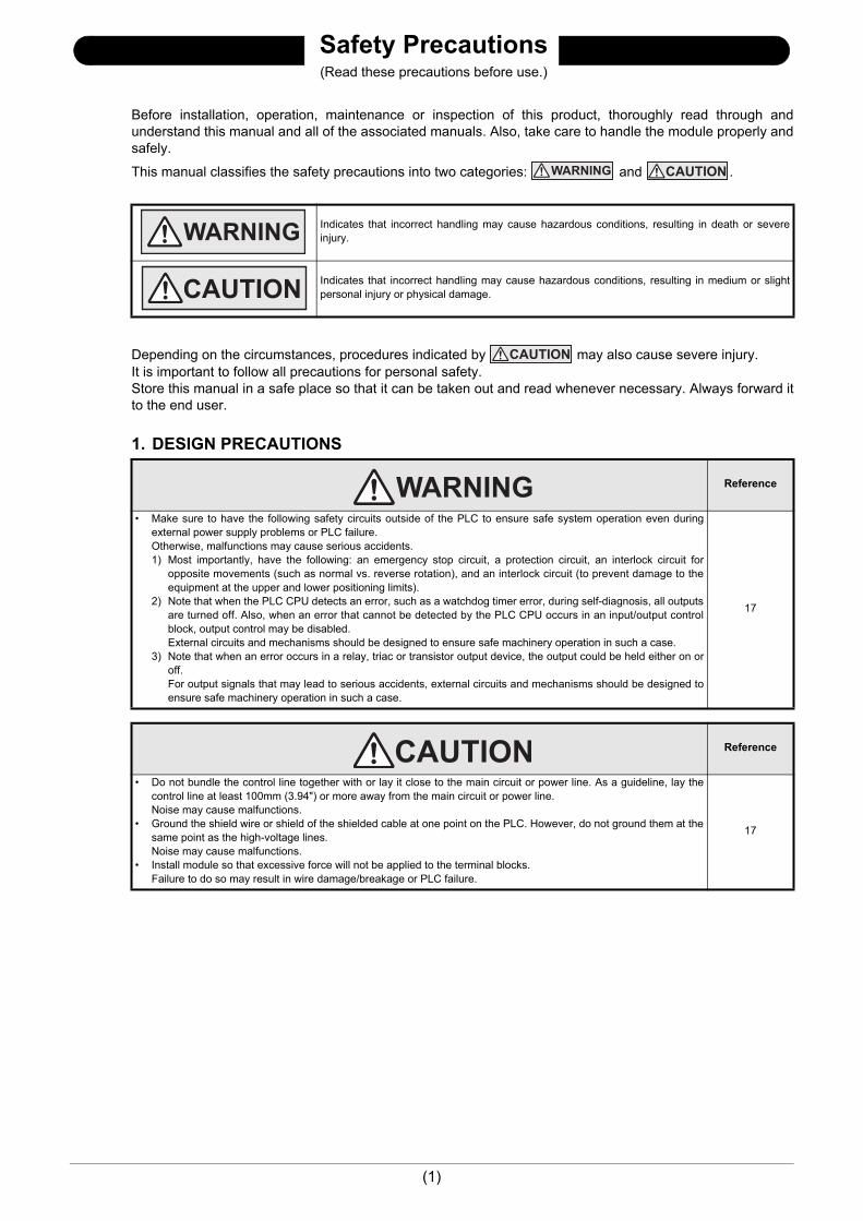
1. DESIGN PRECAUTIONS
Indicates that incorrect handling may cause hazardous conditions, resulting in death or severeinjury.
Indicates that incorrect handling may cause hazardous conditions, resulting in medium or slightpersonal injury or physical damage.
Reference
• Make sure to have the following safety circuits outside of the PLC to ensure safe system operation even duringexternal power supply problems or PLC failure.Otherwise, malfunctions may cause serious accidents.1) Most importantly, have the following: an emergency stop circuit, a protection circuit, an interlock circuit for
opposite movements (such as normal vs. reverse rotation), and an interlock circuit (to prevent damage to theequipment at the upper and lower positioning limits).
2) Note that when the PLC CPU detects an error, such as a watchdog timer error, during self-diagnosis, all outputsare turned off. Also, when an error that cannot be detected by the PLC CPU occurs in an input/output controlblock, output control may be disabled.External circuits and mechanisms should be designed to ensure safe machinery operation in such a case.
3) Note that when an error occurs in a relay, triac or transistor output device, the output could be held either on oroff.For output signals that may lead to serious accidents, external circuits and mechanisms should be designed toensure safe machinery operation in such a case.
17
Reference
• Do not bundle the control line together with or lay it close to the main circuit or power line. As a guideline, lay thecontrol line at least 100mm (3.94") or more away from the main circuit or power line.Noise may cause malfunctions.
• Ground the shield wire or shield of the shielded cable at one point on the PLC. However, do not ground them at thesame point as the high-voltage lines.Noise may cause malfunctions.
• Install module so that excessive force will not be applied to the terminal blocks.Failure to do so may result in wire damage/breakage or PLC failure.
17
Safety Precautions(Read these precautions before use.)
(1)

Safety Precautions(Read these precautions before use.)
2. INSTALLATION PRECAUTIONS
3. WIRING PRECAUTIONS
Reference
• Make sure to cut off all phases of the power supply externally before attempting installing.Failure to do so may cause electric shock or damage to the product. 24
Reference
• Use the product within the generic environment specifications described in PLC main unit manual (HardwareEdition).Never use the product in areas with excessive dust, oily smoke, conductive dusts, corrosive gas (salt air, Cl2, H2S,SO2, or NO2), flammable gas, vibration or impacts, or expose it to high temperature, condensation, or rain andwind.If the product is used in such conditions, electric shock, fire, malfunctions, deterioration or damage may occur.
• Do not touch the conductive parts of the product directly. Doing so may cause device failures or malfunctions.
• Install the product securely using a DIN rail or mounting screws.• Install the product on a flat surface.
If the mounting surface is rough, undue force will be applied to the PC board, thereby causing nonconformities.• When drilling screw holes or wiring, make sure that cutting and wiring debris do not enter the ventilation slits.
Failure to do so may cause fire, equipment failures or malfunctions.• Be sure to remove the dust proof sheet from the PLC's ventilation port when installation work is completed.
Failure to do so may cause fire, equipment failures or malfunctions.• Connect the extension cables securely to their designated connectors.
Loose connections may cause malfunctions.• Turn off the power to the PLC before attaching or detaching the following devices.
Failure to do so may cause device failures or malfunctions.- Peripheral devices, display modules, expansion boards and special adapters- I/O extension units/blocks, FX Series terminal block and the special function units/blocks- Battery and memory cassette
24
Reference
• Make sure to cut off all phases of the power supply externally before attempting wiring work.Failure to do so may cause electric shock or damage to the product. 27
Reference
• Connect the AC power supply to the dedicated terminals specified in this manual.If an AC power supply is connected to a DC input/output terminal or DC power supply terminal, the PLC will burnout.
• Do not wire vacant terminals externally.Doing so may damage the product.
• Use class D grounding (grounding resistance of 100 or less) with a wire of 2mm2 or thicker on the groundingterminal of the PLC.However, do not connect the ground terminal at the same point as a heavy electrical system.
• When drilling screw holes or wiring, make sure cutting or wire debris does not enter the ventilation slits.Failure to do so may cause fire, equipment failures or malfunctions.
• Make sure to observe the following precautions in order to prevent malfunctions under the influence of noise:- Do not bundle the power line or twisted shielded cable together with or lay it close to the main circuit, high-
voltage line, or load line.Otherwise, noise disturbance and/or surge induction are likely to take place. As a guideline, lay the control line at least 100mm (3.94") or more away from the main circuit, high-voltage line, or load line.
- Ground the shield wire or shield of the shielded cable at one point on the PLC. However, do not use common grounding with heavy electrical systems.
• Make sure to properly wire to the terminal blocks in accordance with the following precautions.Failure to do so may cause electric shock, equipment failures, a short-circuit, wire breakage, malfunctions, ordamage to the product.- The disposal size of the cable end should follow the dimensions described in the manual.- Tightening torque should follow the specifications in the manual.
27
(2)

Safety Precautions(Read these precautions before use.)
4. STARTUP AND MAINTENANCE PRECAUTIONS
5. DISPOSAL PRECAUTIONS
6. TRANSPORTATION PRECAUTIONS
Reference
• Do not touch any terminal while the PLC's power is on.Doing so may cause electric shock or malfunctions.
• Before cleaning or retightening terminals, cut off all phases of the power supply externally.Failure to do so may cause electric shock.
• Before modifying or disrupting the program in operation or running the PLC, carefully read through this manual andthe associated manuals and ensure the safety of the operation.An operation error may damage the machinery or cause accidents.
125141
Reference
• Do not disassemble or modify the PLC.Doing so may cause fire, equipment failures, or malfunctions.For repair, contact your local Mitsubishi Electric representative.
• Turn off the power to the PLC before connecting or disconnecting any extension cable.Failure to do so may cause equipment failures or malfunctions.
• Turn off the power to the PLC before attaching or detaching the following devices.Failure to do so may cause equipment failures or malfunctions.- Peripheral devices, display modules, expansion boards and special adapters- I/O extension units/blocks, FX Series terminal block and the special function units/blocks- Battery and memory cassette
125141
Reference
• Please contact a certified electronic waste disposal company for the environmentally safe recycling and disposal ofyour device. 17
Reference
• The PLC is a precision instrument. During transportation, avoid impacts larger than those specified in the generalspecifications of the PLC main unit manual.Failure to do so may cause failures in the PLC.After transportation, verify the operations of the PLC.
17
(3)

Safety Precautions(Read these precautions before use.)
MEMO
(4)

FX3U-4LC User's Manual
FX3U-4LC
User's Manual
ForewordThis manual describes the FX3U-4LC temperature control block and should be read and understood before attempting to install the hardware.Store this manual in a safe place so that you can take it out and read it whenever necessary. Always forward it to the end user.
© 2010 MITSUBISHI ELECTRIC CORPORATION
Manual number JY997D39101
Manual revision D
Date 4/2015
This manual confers no industrial property rights or any rights of any other kind, nor does it confer any patent licenses. MitsubishiElectric Corporation cannot be held responsible for any problems involving industrial property rights which may occur as a result ofusing the contents noted in this manual.
1

FX3U-4LC User's Manual
Outline Precautions• This manual provides information for the use of the FX3U-4LC temperature control block.
The manual has been written to be used by trained and competent personnel. The definition of such a person or persons is as follows;
1) Any engineer who is responsible for the planning, design and construction of automatic equipment usingthe product associated with this manual should be of a competent nature, trained and qualified to thelocal and national standards required to fulfill that role. These engineers should be fully aware of allaspects of safety with aspects regarding to automated equipment.
2) Any commissioning or maintenance engineer must be of a competent nature, trained and qualified to thelocal and national standards required to fulfill the job. These engineers should also be trained in the useand maintenance of the completed product. This includes being familiar with all associated manuals anddocumentation for the product. All maintenance should be carried out in accordance with establishedsafety practices.
3) All operators of the completed equipment should be trained to use that product in a safe and coordinatedmanner in compliance with established safety practices. The operators should also be familiar withdocumentation that is connected with the actual operation of the completed equipment.
Note: The term 'completed equipment' refers to a third party constructed device that contains or uses the product associated with this manual.
• This product has been manufactured as a general-purpose part for general industries, and has not been designed or manufactured to be incorporated in a device or system used in purposes related to human life.
• Before using the product for special purposes such as nuclear power, electric power, aerospace, medicine or passenger movement vehicles, consult with Mitsubishi Electric.
• This product has been manufactured under strict quality control. However when installing the product where major accidents or losses could occur if the product fails, install appropriate backup or failsafe functions into the system.
• When combining this product with other products, please confirm the standards and codes of regulation to which the user should follow. Moreover, please confirm the compatibility of this product with the system, machines, and apparatuses to be used.
• If there is doubt at any stage during installation of the product, always consult a professional electrical engineer who is qualified and trained in the local and national standards. If there is doubt about the operation or use, please consult your local Mitsubishi Electric representative.
• Since the examples within this manual, technical bulletin, catalog, etc. are used as reference; please use it after confirming the function and safety of the equipment and system. Mitsubishi Electric will not accept responsibility for actual use of the product based on these illustrative examples.
• The content, specification etc. of this manual may be changed for improvement without notice.• The information in this manual has been carefully checked and is believed to be accurate; however, if you
notice any doubtful point, error, etc., please contact your local Mitsubishi Electric representative.
Registration• The company name and the product name to be described in this manual are the registered trademarks or
trademarks of each company.
2

FX3U-4LC User's Manual
Table of ContentsSAFETY PRECAUTIONS .................................................................................................. (1)Standards................................................................................................................................... 7
Certification of UL, cUL standards ....................................................................................................... 7 Compliance with EC directive (CE Marking) ........................................................................................ 7
Associated Manuals.................................................................................................................. 9Generic Names and Abbreviations Used in the Manual ...................................................... 11Reading the Manual ................................................................................................................ 13
1. Introduction 14
1.1 Outline........................................................................................................................................... 141.1.1 Major features of the FX3U-4LC .................................................................................................... 14
1.2 External Dimensions and Part Names .......................................................................................... 151.3 Terminal Layout ............................................................................................................................ 161.4 Power and Status LEDs................................................................................................................ 16
2. Specification 17
2.1 General Specifications .................................................................................................................. 182.2 Power Supply Specifications......................................................................................................... 182.3 Performance Specifications .......................................................................................................... 182.4 Input Specifications ....................................................................................................................... 19
2.4.1 Temperature input specifications................................................................................................... 192.4.2 Measurement precision ................................................................................................................. 202.4.3 Current detector (CT) input specifications ..................................................................................... 202.4.4 Measurement value...................................................................................................................... 20
2.5 Input Type ..................................................................................................................................... 212.6 Output Specifications .................................................................................................................... 21
3. System Configuration 22
3.1 General Configuration ................................................................................................................... 223.2 Applicable PLC.............................................................................................................................. 233.3 Connection with PLC..................................................................................................................... 23
4. Installation 24
4.1 DIN rail Mounting .......................................................................................................................... 254.2 Direct Mounting ............................................................................................................................. 26
5. Wiring 27
5.1 Power Supply Wiring..................................................................................................................... 285.1.1 Power supply wiring....................................................................................................................... 285.1.2 Grounding...................................................................................................................................... 28
5.2 Input Wiring ................................................................................................................................... 295.2.1 Wiring example of thermocouple ................................................................................................... 295.2.2 Wiring example of resistance thermometer ................................................................................... 295.2.3 Wiring example of micro voltage input........................................................................................... 30
5.3 Output Wiring ................................................................................................................................ 315.4 Terminal Screw and Tightening Torque........................................................................................ 32
3

FX3U-4LC User's Manual
6. Introduction of Functions 33
6.1 Functions List ................................................................................................................................ 336.2 Control Mode Switch Function ...................................................................................................... 346.3 Transistor Output Selection Function............................................................................................ 366.4 PID control .................................................................................................................................... 38
6.4.1 Easy PID control with two degrees of freedom.............................................................................. 386.4.2 Overshoot prevention function....................................................................................................... 39
6.5 Two-position Control ..................................................................................................................... 406.6 Heating/cooling PID control........................................................................................................... 41
6.6.1 Heating/cooling PID control ........................................................................................................... 416.6.2 Overshoot prevention function....................................................................................................... 426.6.3 Overlap/dead band function .......................................................................................................... 436.6.4 Cooling method ............................................................................................................................. 44
6.7 Cascade control ............................................................................................................................ 456.7.1 Cascade control............................................................................................................................. 456.7.2 Tuning during cascade control ...................................................................................................... 476.7.3 SV tracking selection function ....................................................................................................... 48
6.8 Auto Tuning Function .................................................................................................................... 496.8.1 AT (Auto tuning) ............................................................................................................................ 496.8.2 Conditions for performing and aborting AT (auto tuning) .............................................................. 516.8.3 AT (auto tuning) bias ..................................................................................................................... 53
6.9 Startup Tuning Function................................................................................................................ 546.9.1 ST (startup tuning)......................................................................................................................... 546.9.2 Conditions for performing and aborting ST (startup tuning) .......................................................... 56
6.10 AUTO/MANUAL mode changeover ............................................................................................ 586.10.1 AUTO mode and MANUAL mode................................................................................................ 586.10.2 Balance-less, bump-less function................................................................................................ 59
6.11 Heater Disconnection Alarm Function (HBA).............................................................................. 606.11.1 Heater disconnection alarm function ........................................................................................... 606.11.2 Number of times of heater disconnection alarm delay ................................................................ 61
6.12 Loop Breaking Alarm Function (LBA).......................................................................................... 626.12.1 Loop breaking alarm function ...................................................................................................... 626.12.2 Loop breaking alarm dead zone (LBD)........................................................................................ 64
7. Alarm 65
7.1 Alarm List ...................................................................................................................................... 657.2 Alarm Functions ............................................................................................................................ 67
7.2.1 Upper limit input value alarm......................................................................................................... 677.2.2 Lower limit input value alarm......................................................................................................... 677.2.3 Upper limit deviation alarm............................................................................................................ 687.2.4 Lower limit deviation alarm............................................................................................................ 687.2.5 Upper/lower limit deviation ............................................................................................................ 687.2.6 Range alarm.................................................................................................................................. 697.2.7 Alarm wait operation...................................................................................................................... 697.2.8 Alarm re-wait operation ................................................................................................................. 70
7.3 Alarm Dead Zone Setting.............................................................................................................. 717.4 Number of Times of Alarm Delay .................................................................................................. 72
4

FX3U-4LC User's Manual
8. Buffer Memory 73
8.1 Buffer Memory List ........................................................................................................................ 738.2 Buffer Memory Details................................................................................................................... 77
8.2.1 [BFM#0] Flag................................................................................................................................. 778.2.2 [BFM#1 to 4] Event........................................................................................................................ 788.2.3 [BFM#5 to 8] Measured value (PV) ............................................................................................... 798.2.4 [BFM#9 to 12] Control output value (MV) monitor/
Heating control output value (MV) monitor ............................................................................... 808.2.5 [BFM#13 to 16] Cooling control output value (MV) monitor........................................................... 808.2.6 [BFM#17 to 20] Control output flag................................................................................................ 818.2.7 [BFM#21 to 24] Heater current measured value ........................................................................... 828.2.8 [BFM#25 to 28] External input value ............................................................................................. 828.2.9 [BFM#29] Control start/stop changeover....................................................................................... 828.2.10 [BFM#30] FX Series model code................................................................................................. 828.2.11 [BFM#32 to 35] External output value/Heating external output value monitor ............................ 838.2.12 [BFM#36 to 39] Cooling external output value monitor ............................................................... 838.2.13 [BFM#40 to 43] Set value monitor ............................................................................................... 838.2.14 [BFM#44 to 47] Control mode monitor ........................................................................................ 848.2.15 [BFM#48][BFM#88][BFM#128][BFM#168] Set value (SV) .......................................................... 858.2.16 [BFM#49 to 52][BFM#89 to 92][BFM#129 to 132][BFM#169 to 172]
Alarm setting value 1 to 4 ......................................................................................................... 858.2.17 [BFM#53][BFM#93][BFM#133][BFM#173] Heater disconnection alarm set value ...................... 868.2.18 [BFM#54][BFM#94][BFM#134][BFM#174] AUTO/MANUAL mode changeover ......................... 868.2.19 [BFM#55][BFM#95][BFM#135][BFM#175] MANUAL output set value........................................ 878.2.20 [BFM#56][BFM#96][BFM#136][BFM#176] AT (auto tuning) execution command ...................... 878.2.21 [BFM#57][BFM#97][BFM#137][BFM#177] Operation mode ....................................................... 888.2.22 [BFM#58][BFM#98][BFM#138][BFM#178] Proportional band (P)/
Heating proportional band (P)................................................................................................... 898.2.23 [BFM#59][BFM#99][BFM#139][BFM#179] Cooling proportional band (P) .................................. 898.2.24 [BFM#60][BFM#100][BFM#140][BFM#180] Integral time (I) ....................................................... 908.2.25 [BFM#61][BFM#101][BFM#141][BFM#181] Derivative time (D) ................................................. 908.2.26 [BFM#62][BFM#102][BFM#142][BFM#182] Control response parameter .................................. 918.2.27 [BFM#63][BFM#103][BFM#143][BFM#183] Overlap/Dead band ................................................ 928.2.28 [BFM#64][BFM#104][BFM#144][BFM#184] Output limiter upper limit/
Heating upper output limiter...................................................................................................... 938.2.29 [BFM#65][BFM#105][BFM#145][BFM#185] Output limiter lower limit......................................... 948.2.30 [BFM#66][BFM#106][BFM#146][BFM#186] Cooling upper output limiter setting........................ 948.2.31 [BFM#67][BFM#107][BFM#147][BFM#187] Output change ratio limiter ..................................... 958.2.32 [BFM#68][BFM#108][BFM#148][BFM#188] Sensor correction value setting.............................. 968.2.33 [BFM#69][BFM#109][BFM#149][BFM#189] Adjustment sensitivity (dead zone) setting............. 978.2.34 [BFM#70][BFM#110][BFM#150][BFM#190] Control output cycle setting/
Heating control output period setting ........................................................................................ 988.2.35 [BFM#71][BFM#111][BFM#151][BFM#191] Cooling control output period setting...................... 988.2.36 [BFM#72][BFM#112][BFM#152][BFM#192] Primary delay digital filter setting ........................... 998.2.37 [BFM#73][BFM#113][BFM#153][BFM#193] Setting change ratio limiter................................... 1008.2.38 [BFM#74][BFM#114][BFM#154][BFM#194] AT (auto tuning) bias............................................ 1018.2.39 [BFM#75][BFM#115][BFM#155][BFM#195] Normal/reverse operation selection ..................... 1028.2.40 [BFM#76][BFM#116][BFM#156][BFM#196] Setting limiter upper limit...................................... 1038.2.41 [BFM#77][BFM#117][BFM#157][BFM#197] Setting limiter lower limit ...................................... 1038.2.42 [BFM#78][BFM#118][BFM#158][BFM#198] Loop breaking alarm judgement time................... 1048.2.43 [BFM#79][BFM#119][BFM#159][BFM#199] Loop breaking alarm dead zone........................... 1058.2.44 [BFM#80][BFM#120][BFM#160][BFM#200] Micro voltage input scaling upper limit ................. 1068.2.45 [BFM#81][BFM#121][BFM#161][BFM#201] Micro voltage input scaling lower limit.................. 1068.2.46 [BFM#82][BFM#122][BFM#162][BFM#202] External input range upper limit ........................... 1068.2.47 [BFM#83][BFM#123][BFM#163][BFM#203] External input range lower limit ............................ 1068.2.48 [BFM#84][BFM#124][BFM#164][BFM#204] External output range upper limit ......................... 1078.2.49 [BFM#85][BFM#125][BFM#165][BFM#205] External output range lower limit.......................... 1078.2.50 [BFM#86][BFM#126][BFM#166][BFM#206] Transistor output selection ................................... 1088.2.51 [BFM#87][BFM#127][BFM#167][BFM#207] ST (startup tuning) execution command .............. 1098.2.52 [BFM#208][BFM#214][BFM#220][BFM#226] Input type ........................................................... 1108.2.53 [BFM#209 to #212][BFM#215 to #218][BFM#221 to #224][BFM#227 to #230]
Alarm mode setting................................................................................................................. 111
5

FX3U-4LC User's Manual
8.2.54 [BFM#232] Cooling method setting ........................................................................................... 1128.2.55 [BFM#233] Alarm dead band setting ......................................................................................... 1138.2.56 [BFM#234] Alarm delay count ................................................................................................... 1148.2.57 [BFM#235] Number of times of heater disconnection alarm delay/
Number of times of current error detection when output is OFF delay ................................... 1158.2.58 [BFM#236] Temperature rise completion range setting ............................................................ 1158.2.59 [BFM#237] Temperature rise completion soak time.................................................................. 1168.2.60 [BFM#238] CT monitor method switch ...................................................................................... 1178.2.61 [BFM#239] CT ratio setting........................................................................................................ 1178.2.62 [BFM#240, #241] Control mode switch ..................................................................................... 1188.2.63 [BFM#242, #243] SV tracking selection .................................................................................... 1198.2.64 [BFM#244, #245] Cascade ON/OFF ......................................................................................... 1208.2.65 [BFM#246, #247] Cascade gain ................................................................................................ 1208.2.66 [BFM#248, #249] Cascade bias ................................................................................................ 1218.2.67 [BFM#250, #251] Cascade monitor........................................................................................... 1218.2.68 [BFM#252] Set value range error address ................................................................................ 1228.2.69 [BFM#253] Error reset command .............................................................................................. 1228.2.70 [BFM#254] Set value backup command.................................................................................... 1238.2.71 [BFM#255] Initialization command ............................................................................................ 124
9. Program Examples 125
9.1 Reading/Writing Buffer Memory .................................................................................................. 1269.1.1 Assigned unit number.................................................................................................................. 1269.1.2 How to read/write from/to buffer memory .................................................................................... 126
9.2 Example of a Program for PID Control........................................................................................ 1319.2.1 System configuration ................................................................................................................... 1319.2.2 Conditions of operation................................................................................................................ 1319.2.3 Device assignments .................................................................................................................... 1329.2.4 Sequence program...................................................................................................................... 133
9.3 Example of a Program for Heating/Cooling PID Control ............................................................. 1369.3.1 System configuration ................................................................................................................... 1369.3.2 Conditions of operation................................................................................................................ 1369.3.3 Device assignments .................................................................................................................... 1379.3.4 Sequence program...................................................................................................................... 138
10. Troubleshooting 141
10.1 Troubleshooting Procedure....................................................................................................... 14210.1.1 How to reset an error................................................................................................................. 142
10.2 Diagnostics on the PLC Main Unit ............................................................................................ 14310.2.1 POWER (POW) LED [on/flashing/off]........................................................................................ 14310.2.2 BATT (BAT) LED [on/off] ........................................................................................................... 14310.2.3 ERROR (ERR) LED [on/flashing/off] ......................................................................................... 144
Appendix A: Version Information 145
Appendix A-1 Version Information ............................................................................................ 145Appendix A-1-1 Version check method ................................................................................................ 145Appendix A-1-2 Version upgrade history.............................................................................................. 145
Warranty................................................................................................................................. 147
Revised History ..................................................................................................................... 148
6

StandardsFX3U-4LC User's Manual
Standards
Certification of UL, cUL standards
FX3U-4LC units comply with the UL standards (UL, cUL).
UL, cUL File number :E95239
Regarding the standards that comply with the main unit, please refer to either the FX series product catalog orconsult with your nearest Mitsubishi product provider.
Compliance with EC directive (CE Marking)
This document does not guarantee that a mechanical system including this product will comply with thefollowing standards.Compliance to EMC directive and LVD directive for the entire mechanical module should be checked by theuser / manufacturer. For more information please consult with your nearest Mitsubishi product provider.Regarding the standards that comply with the main unit, please refer to either the FX series product catalog orconsult with your nearest Mitsubishi product provider.
Requirement for Compliance with EMC directive
The following products have shown compliance through direct testing (of the identified standards below) and design analysis (through the creation of a technical construction file) to the European Directive for Electromagnetic Compatibility (2004/108/EC) when used as directed by the appropriate documentation.
Attention• This product is designed for use in industrial applications.
Note• Authorized Representative in the European Community:
Mitsubishi Electric Europe B.V.Gothaer Str. 8, 40880 Ratingen, Germany
Type: Programmable Controller (Open Type Equipment)Models: MELSEC FX3U series manufactured from December 1st, 2009 FX3U-4LC
Standard Remark
EN61131-2:2007Programmable controllers
- Equipment requirements and tests
Compliance with all relevant aspects of the standard.EMI• Radiated Emission• Conducted EmissionEMS• Radiated electromagnetic field• Fast Transient burst• Electrostatic discharge• High-energy surge• Voltage drops and interruptions• Conducted RF• Power frequency magnetic field
7

StandardsFX3U-4LC User's Manual
Caution to conform with EC Directives
The FX3U-4LC have been found to be compliant to the European standards in the aforesaid manual and directive. However, for the very best performance from what are in fact delicate measuring and controlled output device Mitsubishi Electric would like to make the following points;As analog devices are sensitive by nature, their use should be considered carefully. For users of proprietary cables (integral with sensors or actuators), these users should follow those manufacturers installation requirements.Mitsubishi Electric recommend that shielded cables should be used. If NO other EMC protection is provided, then users may experience temporary loss or accuracy between ±10% in very heavy industrial areas.However, Mitsubishi Electric suggest that if adequate EMC precautions are followed for the users complete control system, users should expect accuracy as specified in this manual.• Sensitive analog cable should not be laid in the same trunking or cable conduit as high voltage cabling.
Where possible users should run analog cables separately.• Good cable shielding should be used. When terminating the shield at Earth - ensure that no earth loops are
accidentally created.• When reading analog values, EMC accuracy can be improved out by averaging the readings. This can be
achieved either through functions on the analog special function blocks for or through a users program in the FX3G/FX3U/FX3GC/FX3UC Series PLC main unit.
• Installation in EnclosureProgrammable logic controllers are open-type devices that must be installed and used within conductive control cabinets. Please use the programmable logic controller while installed within a conductive shielded control cabinet. Please secure the cabinet door to the control cabinet (for conduction).Installation within a control cabinet greatly affects the safety of the system and aids in shielding noise from the programmable logic controller.
8

Associated ManualsFX3U-4LC User's Manual
Associated ManualsOnly the installation manual is packed together with the FX3U-4LC temperature control block.For a detailed explanation of the FX3U-4LC temperature control block, refer to this manual.For the hardware information and instructions on the PLC main unit, refer to the respective manuals.
Refer to these manualsRefer to the appropriate equipment manualFor a detailed explanation, refer to an additional manual
Title of manual Documentnumber Description Model code
Manual for the Main UnitFX3G Series PLCs Main Unit
SuppliedManual
FX3G SeriesHardware Manual JY997D33401
Describes FX3G Series PLC specification for I/O, wiringand installation extracted from the FX3G User's Manual- Hardware Edition.For details, refer to FX3G Series User's Manual -Hardware Edition.
-
AdditionalManual
FX3G SeriesUser's Manual- Hardware Edition
JY997D31301 Describes FX3G Series PLC specification details for I/O,wiring, installation and maintenance. 09R521
FX3U Series PLCs Main Unit
SuppliedManual
FX3U SeriesHardware Manual JY997D18801
Describes FX3U Series PLC specification for I/O, wiringand installation extracted from the FX3U User's Manual -Hardware Edition.For details, refer to FX3U Series User's Manual -Hardware Edition.
-
AdditionalManual
FX3U SeriesUser's Manual- Hardware Edition
JY997D16501 Describes FX3U Series PLC specification details for I/O,wiring, installation and maintenance. 09R516
FX3GC Series PLCs Main Unit
SuppliedManual
FX3GC SeriesHardware Manual JY997D45201
Describes FX3GC Series PLC specification for I/O,wiring and installation extracted from the FX3GC User'sManual - Hardware Edition.For details, refer to FX3GC Series User's Manual -Hardware Edition.
-
AdditionalManual
FX3GC SeriesUser's Manual- Hardware Edition
JY997D45401 Describes FX3GC Series PLC specification details for I/O, wiring, installation and maintenance. 09R533
FX3UC Series PLCs Main Unit
SuppliedManual
FX3UC (D, DS, DSS) SeriesHardware Manual JY997D28601
Describes FX3UC (D, DS, DSS) Series PLC specificationfor I/O, wiring and installation extracted from the FX3UCSeries User's Manual - Hardware Edition.For details, refer to FX3UC Series User's Manual -Hardware Edition.
-
SuppliedManual
FX3UC-32MT-LT-2Hardware Manual JY997D31601
Describes FX3UC-32MT-LT-2 specification for I/O,wiring and installation extracted from the FX3UC User'sManual - Hardware Edition.For details, refer to FX3UC Series User's Manual -Hardware Edition.
-
SuppliedManual
FX3UC-32MT-LTHardware Manual(Only Japanese document)
JY997D12701
Describes FX3UC-32MT-LT specification for I/O, wiringand installation extracted from the FX3UC User's Manual- Hardware Edition.For details, refer to FX3UC Series User's Manual -Hardware Edition.
-
AdditionalManual
FX3UC SeriesUser's Manual- Hardware Edition
JY997D28701 Describes FX3UC Series PLC specification detailsfor I/O, wiring, installation and maintenance. 09R519
Programming for FX3G/FX3GC/FX3U/FX3UC Series
AdditionalManual
FX3S/FX3G/FX3GC/FX3U/FX3UC Series Programming Manual- Basic & AppliedInstruction Edition
JY997D16601 Describes FX3S/FX3G/FX3GC/FX3U/FX3UC Series PLC programming for basic/applied instructions and devices. 09R517
9

Associated ManualsFX3U-4LC User's Manual
AdditionalManual
MELSEC-Q/L/F Structured Programming Manual (Fundamentals)
SH-080782 Programming methods, specifications, functions, etc.required to create structured programs. 13JW06
AdditionalManual
FX CPU Structured Programming Manual [Device & Common]
JY997D26001 Devices, parameters, etc. provided in structuredprojects of GX Works2. 09R925
AdditionalManual
FX CPU Structured Programming Manual [Basic & Applied Instruction]
JY997D34701 Sequence instructions provided in structured projects ofGX Works2. 09R926
AdditionalManual
FX CPU Structured Programming Manual [Application Functions]
JY997D34801 Application functions provided in structured projects ofGX Works2. 09R927
Manuals for analog control
AdditionalManual
FX3S/FX3G/FX3GC/FX3U/FX3UC Series User's Manual- Analog Control Edition
JY997D16701Details of analog special function block(FX3U-4AD, FX3U-4DA, FX3UC-4AD) andanalog special adapter (FX3U-***-**-ADP)
09R619
Manuals for FX3U-4LC temperature control block
SuppliedManual
FX3U-4LCInstallation Manual JY997D38901
Describes installation specifications for the FX3U-4LCtemperature control block extracted from the FX3U-4LCUser's Manual.For details, refer to FX3U-4LC User's Manual.
-
AdditionalManual
FX3U-4LCUser's Manual(This Manual)
JY997D39101 Describes details of the FX3U-4LC temperature controlblock. 09R625
Title of manual Documentnumber Description Model code
10

Generic Names and Abbreviations Used in the ManualFX3U-4LC User's Manual
Generic Names and Abbreviations Used in the Manual
Generic name or abbreviation DescriptionPLCFX3G series Generic name for FX3G Series PLC
FX3G PLC or main unit Generic name for FX3G Series PLC main unit
FX3U series Generic name for FX3U Series PLC
FX3U PLC or main unit Generic name for FX3U Series PLC main unit
FX3GC series Generic name for FX3GC Series PLC
FX3GC PLC or main unit Generic name for FX3GC Series PLC main unit
FX3UC series Generic name for FX3UC Series PLC
FX3UC PLC or main unit Generic name for FX3UC Series PLC main unit
Expansion board
Expansion board
Generic name for expansion boardThe number of connectable units, however, depends on the type of main unit.To check the number of connectable units, refer to the User's Manual - Hardware Edition of the mainunit to be used for your system.
Special adapter
Special adapter
Generic name for high-speed input/output special adapter, communication special adapter, analogspecial adapter, and CF card special adapter.The number of connectable units, however, depends on the type of main unit.To check the number of connectable units, refer to the User's Manual - Hardware Edition of the mainunit to be used for your system.
Extension equipment
I/O extension unit/block
Generic name for input/output powered extension unit and input/output extension blockThe number of connectable units, however, depends on the type of main unit.To check the number of connectable units, refer to the User's Manual - Hardware Edition of the mainunit to be used for your system.
Special function unit/block orSpecial extension unit
Generic name for special function unit and special function blockThe number of connectable units, however, depends on the type of main unit.To check the number of connectable units, refer to the User's Manual - Hardware Edition of the mainunit to be used for your system.
Special function unit Generic name for special function unit
Special function block
Generic name for special function blockThe number of connectable units, however, depends on the type of main unit.To check the number of connectable units, refer to the User's Manual - Hardware Edition of the mainunit to be used for your system.
4LC Abbreviated name for FX3U-4LC
Optional unitMemory cassette Generic name for FX3U-FLROM-16, FX3U-FLROM-64, FX3U-FLROM-64L, FX3U-FLROM-1M
Battery Abbreviated name for FX3U-32BL
FX Series terminal blockFX-16E-TB, FX-32E-TB, FX-16EX-A1-TB, FX-16EYR-TB, FX-16EYT-TB, FX-16EYT-H-TB, FX-16EYS-TB, FX-16E-TB/UL, FX-32E-TB/UL, FX-16EYR-ES-TB/UL, FX-16EYT-ES-TB/UL, FX-16EYT-ESS-TB/UL, FX-16EYS-ES-TB/UL
Peripheral unitPeripheral unit Generic name for programming software, handy programming panel, and indicator
Programming toolProgramming tool Generic name for programming software and handy programming panel
Programming software Generic name for programming software
GX Works2 Generic name for SW DNC-GXW2-J/SW DNC-GXW2-E programming software package
GX Developer Generic name for SW D5C-GPPW-J/SW D5C-GPPW-E programming software package
FX-PCS/WIN(-E) Generic name for FX-PCS/WIN or FX-PCS/WIN-E programming software package
Handy programming panel (HPP) Generic name for FX-30P, FX-20P-SET0, FX-20P, FX-20P-E-SET0 and FX-20P-E
11

Generic Names and Abbreviations Used in the ManualFX3U-4LC User's Manual
IndicatorGOT1000 series Generic name for GT15, GT11 and GT10
GOT-900 series Generic name for GOT-A900 series and GOT-F900 series
GOT-A900 series Generic name for GOT-A900 series
GOT-F900 series Generic name for GOT-F900 series
ET-940 series Generic name for ET-940 seriesOnly manuals in Japanese are available for these products
ManualFX3G Hardware Edition FX3G Series User's Manual - Hardware Edition
FX3U Hardware Edition FX3U Series User's Manual - Hardware Edition
FX3GC Hardware Edition FX3GC Series User's Manual - Hardware Edition
FX3UC Hardware Edition FX3UC Series User's Manual - Hardware Edition
Programming manual FX3S/FX3G/FX3GC/FX3U/FX3UC Series Programming Manual - Basic and Applied Instructions Edition
Communication control Edition FX Series User's Manual - Data Communication Edition
Analog control Edition FX3S/FX3G/FX3GC/FX3U/FX3UC Series User's Manual - Analog Control Edition
Positioning control Edition FX3S/FX3G/FX3GC/FX3U/FX3UC Series User's Manual - Positioning Control Edition
Generic name or abbreviation Description
12

Reading the ManualFX3U-4LC User's Manual
Reading the ManualIn this manual, the following formats are used for describing the common items.
The above is different from the actual page, as it is provided for explanation only.
3 System Configuration3.2 Applicable PLC
23
FX3U-4LC User's Manual
1
Introduction
2
Specification
3
System
Configuration
4
Installation
5
Wiring
6
Introduction of Functions
7
Alarm
8
Buffer Mem
ory
9
ProgramExam
ples
10
Troubleshooting
3.2 Applicable PLC
The version number can be checked by reading the last three digits of device D8001/D8101.*1. An FX2NC-CNV-IF or FX3UC-1PS-5V is necessary to connect the 4LC with the FX3GC/FX3UC PLC.
3.3 Connection with PLC
The 4LC connects with a PLC via an extension cable.The 4LC is handled as a special extension block of the PLC. The unit number of the 4LC is automaticallyassigned No.0 to No.7 (Unit No.1 to No.7 is assigned when the main unit is an FX3UC-32MT-LT(-2).) startingfrom the special function unit/block closest to the PLC main unit. (This unit number is used for the designation of a FROM/TO instruction.) For details on the assignment of the I/O number and unit number of the PLC, refer to the following manualcorresponding to the connected PLC.
→ Refer to FX3G Hardware Edition.→ Refer to FX3U Hardware Edition.
→ Refer to FX3GC Hardware Edition.→ Refer to FX3UC Hardware Edition.
• An FX2NC-CNV-IF or FX3UC-1PS-5V is necessary to connect the 4LC with the FX3GC/FX3UC PLC.• The number of I/O points occupied by the 4LC is eight. Make sure that the total number of I/O points
(occupied I/O points) of the main unit, extension unit(s), extension block(s) and the number of points occupied by special function blocks does not exceed the maximum number of I/O points of the PLC.For information on the maximum number of I/O points of the PLC, refer to the respective product manual.
→ Refer to FX3G Hardware Edition.→ Refer to FX3U Hardware Edition.
→ Refer to FX3GC Hardware Edition.→ Refer to FX3UC Hardware Edition.
Model name Applicability
FX3G Series PLC Ver. 1.00 and later(Up to 8 blocks can be connected)
FX3GC Series PLC Ver. 1.40 and later(Up to 6 blocks can be connected)
FX3U Series PLC Ver. 2.20 and later(Up to 8 blocks can be connected)
FX3UC Series PLC*1 Ver. 2.20 and later(Up to 6 blocks can be connected)
POWER
MOTOR-YSTARTDOGINT0INT1 A B
X-READYY-READYX-ERRORY-ERROR
STARTDOGINT0INT1 A B
MOTOR-X
FX3U-64CCL
POWER
RUNERR.RUNERR. SD RD
LL
Otherextensionunits/blocks
FX3U-4LC
FX3G/FX3U PLC FX3U-4LC
FX3GC/FX3UC PLC
FX2NC-CNV-IF
Otherextensionunits/blocks
This area shows the title of the chapter and the title of the section for the current page.
This area shows the manual title for the current page.
The " " mark indicates a reference destination and reference manual.
Shows the reference.
Indexes the chapter number.Shows the title of the chapter and the title
of the section.Shows the manual title.
The right side of each page indexes the chapter number for the page currently opened.
13

1 Introduction1.1 OutlineFX3U-4LC User's Manual
1. Introduction
1.1 Outline
The temperature control block FX3U-4LC (hereinafter called 4LC) equipped with 4 channel input(thermocouples, resistance thermometer and micro voltage input), 4 points output (open collector transistor)and 4 points CT input is a special function block for thermometer control.
1.1.1 Major features of the FX3U-4LC
The 4LC has the following features.1) Allows inputs from 4 channels.
The 4LC supports temperature sensor inputs from thermocouples and resistance thermometers as wellas micro voltage inputs.
2) Incorporates outputs from 4 channels.The 4LC incorporates NPN open collector transistor outputs.
3) Performs heating/cooling PID control.The 4LC handles two systems of outputs, heating output and cooling output, and performs heating/cooling control.
4) Performs cascade control.The 4LC performs cascade control through combination of two control loops, the master loop and slaveloop.
5) Performs control using external analog inputs/outputs.The 4LC performs PID control using voltage/current inputs and voltage/current outputs when combinedwith a special function block for analog input/output.
6) Performs auto tuning.The 4LC can automatically measure, calculate and set optimal PID constants for the preset temperature.
7) Performs startup tuning.The 4LC can automatically calculate and set PID constants based on the response characteristics of thecontrol target when control is started or when the set value (SV) is changed.
8) Detects heater disconnection.The 4LC can detect heater disconnection using the current detector (CT).
9) Backs up set values using the EEPROM.The 4LC can back up set values stored in buffer memories using the built-in EEPROM.
10) Connectable PLCConnect the 4LC to the FX3G/FX3U/FX3GC/FX3UC Series PLC.An FX2NC-CNV-IF or FX3UC-1PS-5V is necessary to connect the 4LC with the FX3GC/FX3UC PLC.
14

1 Introduction1.2 External Dimensions and Part NamesFX3U-4LC User's Manual
1
Introduction
2
Specification
3
System
Configuration
4
Installation
5
Wiring
6
Introduction of Functions
7
Alarm
8
Buffer Mem
ory
9
Program
Examples
10
Troubleshooting
1.2 External Dimensions and Part Names
[1] Extension cable [8] DIN rail mounting groove(DIN rail: DIN46277, 35mm (1.38") width)
[2] Direct mounting hole2 holes of 4.5 (0.18") (mounting screw: M4 screw)
[9] DIN rail mounting hook
[3] Terminal block covers [10] Power supply terminal block (M3 screw)→ Refer to Section 1.3.
[4] Terminal cover [11] Input terminal block (M3 screw)→ Refer to Section 1.3.
[5] Power LED (green) [12] Output terminal block (M3 screw)→ Refer to Section 1.3.
[6] Status LEDs (red)→ Refer to Section 1.4.
[13] Extension connector
[7] Nameplate
2-Ø4.5mounting holes
[1] [2] [4] [5] [6]
82(3.23")(mounting hole pitch)
90(3.55")[4]
[7]
[8]
[9]
86(3.39")
9(0.36")
Unit: mm(inches)MASS(Weight): 0.4kg(0.88lbs)
[10] [11] [12]
[13]
[11] [12]
82
(3.2
3")
(mo
un
ting
ho
le p
itch
)
90
(3.5
5")
Accessaries: Label for indication of special unit/block number, Dust proof sheet, Manual supplied with product
[Without cover]
[3]
[3]
15
1 Introduction1.3 Terminal LayoutFX3U-4LC User's Manual
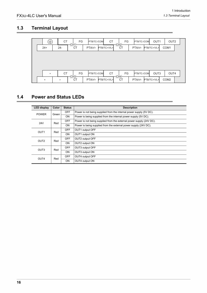
1.3 Terminal Layout
1.4 Power and Status LEDs
LED display Color Status Description
POWER GreenOFF Power is not being supplied from the internal power supply (5V DC).
ON Power is being supplied from the internal power supply (5V DC).
24V RedOFF Power is not being supplied from the external power supply (24V DC).
ON Power is being supplied from the external power supply (24V DC).
OUT1 RedOFF OUT1 output OFF
ON OUT1 output ON
OUT2 RedOFF OUT2 output OFF
ON OUT2 output ON
OUT3 RedOFF OUT3 output OFF
ON OUT3 output ON
OUT4 RedOFF OUT4 output OFF
ON OUT4 output ON
PTB/TC-/COM CT FG PTB/TC-/COM OUT1 OUT2FGCT
PTB/TC+/VL+ CT PTB/TC+/VL+ COM1CT24-24+ PTA/ / PTA/ /CH2CH1
CT FG OUT3 OUT4FGCT PTB/TC-/COM PTB/TC-/COM
PTB/TC+/VL+ CT PTB/TC+/VL+ COM2CT PTA/ / PTA/ /CH3 CH4
16

2 Specification
FX3U-4LC User's Manual
1
Introduction
2
Specification
3
System
Configuration
4
Installation
5
Wiring
6
Introduction of Functions
7
Alarm
8
Buffer Mem
ory
9
Program
Examples
10
Troubleshooting
2. Specification
DESIGN PRECAUTIONS
• Make sure to have the following safety circuits outside of the PLC to ensure safe system operation even during external power supplyproblems or PLC failure.Otherwise, malfunctions may cause serious accidents.1) Most importantly, have the following: an emergency stop circuit, a protection circuit, an interlock circuit for opposite movements
(such as normal vs. reverse rotation), and an interlock circuit (to prevent damage to the equipment at the upper and lowerpositioning limits).
2) Note that when the PLC CPU detects an error, such as a watchdog timer error, during self-diagnosis, all outputs are turned off.Also, when an error that cannot be detected by the PLC CPU occurs in an input/output control block, output control may bedisabled.External circuits and mechanisms should be designed to ensure safe machinery operation in such a case.
3) Note that when an error occurs in a relay, triac or transistor output device, the output could be held either on or off.For output signals that may lead to serious accidents, external circuits and mechanisms should be designed to ensure safemachinery operation in such a case.
DESIGN PRECAUTIONS
• Do not bundle the control line together with or lay it close to the main circuit or power line. As a guideline, lay the control line at least100mm (3.94") or more away from the main circuit or power line.Noise may cause malfunctions.
• Ground the shield wire or shield of the shielded cable at one point on the PLC. However, do not ground them at the same point as thehigh-voltage lines.Noise may cause malfunctions.
• Install module so that excessive force will not be applied to the terminal blocks.Failure to do so may result in wire damage/breakage or PLC failure.
DISPOSAL PRECAUTIONS
• Please contact a certified electronic waste disposal company for the environmentally safe recycling and disposal of your device.
TRANSPORTATION PRECAUTIONS
• The PLC is a precision instrument. During transportation, avoid impacts larger than those specified in the general specifications of thePLC main unit manual.Failure to do so may cause failures in the PLC.After transportation, verify the operations of the PLC.
17

2 Specification2.1 General SpecificationsFX3U-4LC User's Manual
2.1 General Specifications
For items not listed below, specifications are the same as the of the PLC main unit.For general specifications, refer to the manual of the PLC main unit.
→ Refer to FX3G Hardware Edition.→ Refer to FX3U Hardware Edition.
→ Refer to FX3GC Hardware Edition.→ Refer to FX3UC Hardware Edition.
2.2 Power Supply Specifications
2.3 Performance Specifications
Item SpecificationDielectric withstand voltage 500V AC for one minute
Between all terminals and ground terminalInsulation resistance 5M or more by 500V DC Megger
Item Specification
Interface driving power 24V DC +20% -15% 50mAConnect a 24V DC power supply to the terminal block.
CPU driving power 5V DC 160mA5V DC power is supplied internally from the main unit.
Item Specification
Control method
Two-position controlPID controlHeating/cooling PID controlCascade control
Control operation period 250ms/4ch
Set temperature range Equivalent to input range (Refer to Subsection 8.2.52.)
Heater disconnection detection Alarm is detected by buffer memory(Variable within range from 0.0 to 100.0A.)
Operation mode
0 : Not used1 : Monitor2 : Monitor + Alarm3 : Monitor + Alarm + Control(Selected by buffer memory)
Self-diagnosis function Adjustment data check, input value check, watch dog timer check.When abnormality is detected, transistor output turns OFF.
Memory Built-in EEPROM (Number of times of overwrite : 100,000 times)
Insulation method
• The photocoupler is used to insulate the analog input area from the PLC.• The DC/DC converter is used to insulate the power supply from the analog
inputs.• Channels are insulated from each other.
Number of I/O occupied points 8 points(Taken from either the input or output points of the PLC.)
18
2 Specification2.4 Input SpecificationsFX3U-4LC User's Manual
1
Introduction
2
Specification
3
System
Configuration
4
Installation
5
Wiring
6
Introduction of Functions
7
Alarm
8
Buffer Mem
ory
9
Program
Examples
10
Troubleshooting
2.4 Input Specifications
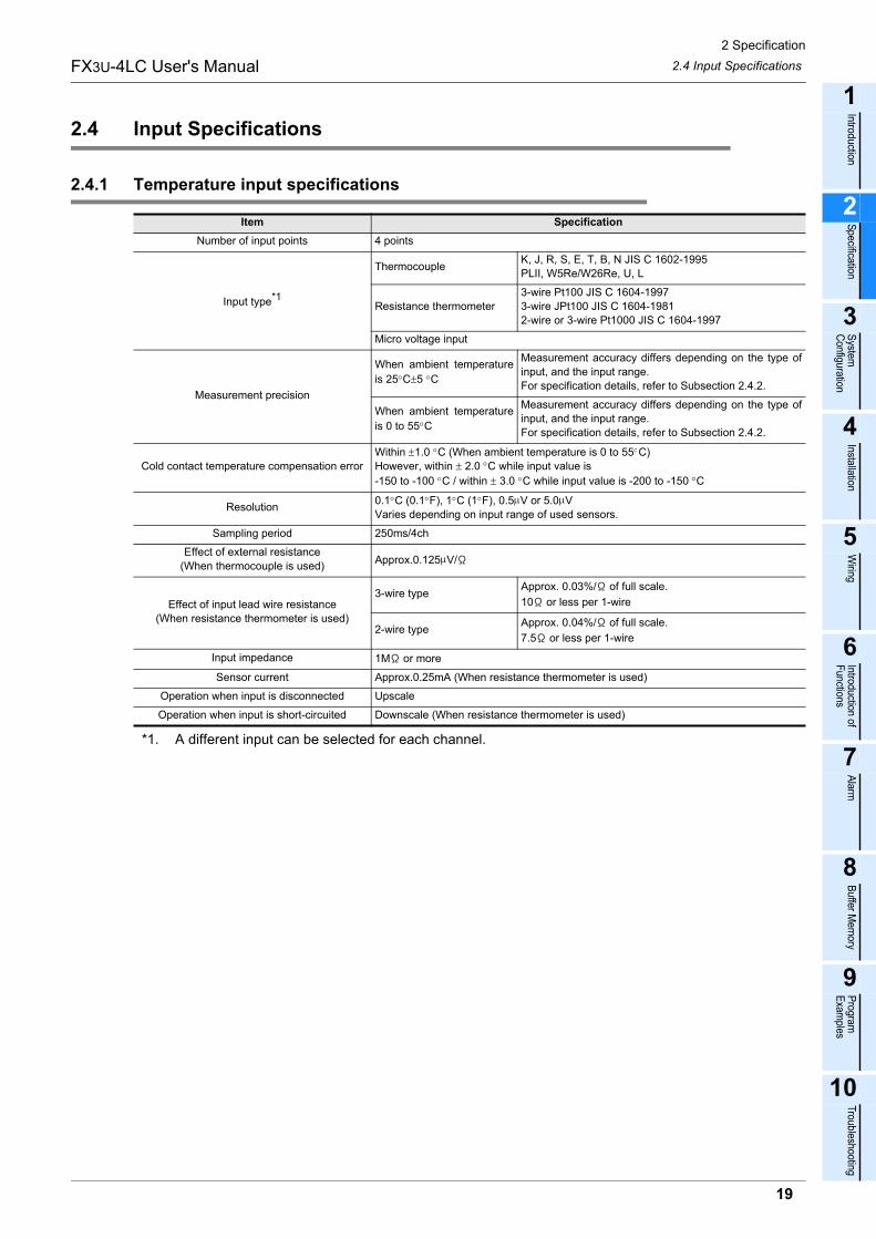
2.4.1 Temperature input specifications
*1. A different input can be selected for each channel.
Item SpecificationNumber of input points 4 points
Input type*1
Thermocouple K, J, R, S, E, T, B, N JIS C 1602-1995PLII, W5Re/W26Re, U, L
Resistance thermometer3-wire Pt100 JIS C 1604-19973-wire JPt100 JIS C 1604-19812-wire or 3-wire Pt1000 JIS C 1604-1997
Micro voltage input
Measurement precision
When ambient temperatureis 25 C±5 C
Measurement accuracy differs depending on the type ofinput, and the input range.For specification details, refer to Subsection 2.4.2.
When ambient temperatureis 0 to 55 C
Measurement accuracy differs depending on the type ofinput, and the input range.For specification details, refer to Subsection 2.4.2.
Cold contact temperature compensation errorWithin ±1.0 C (When ambient temperature is 0 to 55 C)However, within ± 2.0 °C while input value is -150 to -100 C / within ± 3.0 C while input value is -200 to -150 °C
Resolution 0.1 C (0.1 F), 1 C (1 F), 0.5 V or 5.0 VVaries depending on input range of used sensors.
Sampling period 250ms/4ch
Effect of external resistance (When thermocouple is used) Approx.0.125 V/
Effect of input lead wire resistance(When resistance thermometer is used)
3-wire type Approx. 0.03%/ of full scale. 10 or less per 1-wire
2-wire type Approx. 0.04%/ of full scale. 7.5 or less per 1-wire
Input impedance 1M or more
Sensor current Approx.0.25mA (When resistance thermometer is used)
Operation when input is disconnected Upscale
Operation when input is short-circuited Downscale (When resistance thermometer is used)
19

2 Specification2.4 Input SpecificationsFX3U-4LC User's Manual
2.4.2 Measurement precision
The measurement precision is as shown below. The measurement precision of the thermocouple does notinclude the cold contact temperature compensation error. For the cold contact temperature compensationerror, refer to Subsection 2.4.1.Digits below the minimum resolution (shown in the measurement precision below) of the input value arerounded up.
1. When ambient temperature is 25 C±5 C
2. When ambient temperature is 0 to 55 C
2.4.3 Current detector (CT) input specifications
2.4.4 Measurement value
To stabilize the measurement precision, warm-up the system for 30 minutes or more after power-on.
Input type Input range Measurement precision
K, J, E, T, PLII, U, L
Less than -100 C ±3.0 C±1digit
-100 C to less than 500 C ±1.5 C±1digit
500 C or more ±(0.3% of input value)±1digit
R, S, N, W5Re/W26ReLess than 1000 C ±3.0 C±1digit
1000 C or more ±(0.3% of input value)±1digit
B
Less than 400 C ±70 C±1digit
400 C to less than 1000 C ±3 C±1digit
1000 C or more ±(0.3% of input value)±1digit
Pt100, JPt100, Pt1000Less than 200 C ±0.6 C±1digit
200 C or more ±(0.3% of input value)±1digit
Micro voltage input - ±(0.3% of span)±1digit
Input type Input range Measurement precision
K, J, E, T, PLII, U, L
Less than -100 C ±7.0 C±1digit
-100 C to less than 500 C ±3.5 C±1digit
500 C or more ±(0.7% of input value)±1digit
R, S, N, W5Re/W26ReLess than 1000 C ±3.0 C±1digit
1000 C or more ±(0.7% of input value)±1digit
B
Less than 400 C ±140 C±1digit
400 C to less than 1000 C ±7 C±1digit
1000 C or more ±(0.7% of input value)±1digit
Pt100, JPt100, Pt1000Less than 200 C ±1.4 C±1digit
200 C or more ±(0.7% of input value)±1digit
Micro voltage input - ±(0.7% of span)±1digit
Item SpecificationNumber of input points 4 points
Current detector CTL-12-S36-8, CTL-12-S56-10, CTL-6-P-H(manufactured by U.R.D. Co., Ltd.)
Heater current measured value
When CTL-12-S36-8 is used 0.0 to 100.0A
When CTL-12-S56-10 is used 0.0 to 100.0A
When CTL-6-P-H is used 0.0 to 30.0A
Measurement precision Larger one between ±5% of input value and ±2A(Excluding precision of current detector)
Sampling period 0.5 sec.
Input resistance 2.5Ω
20
2 Specification2.5 Input TypeFX3U-4LC User's Manual
1
Introduction
2
Specification
3
System
Configuration
4
Installation
5
Wiring
6
Introduction of Functions
7
Alarm
8
Buffer Mem
ory
9
Program
Examples
10
Troubleshooting
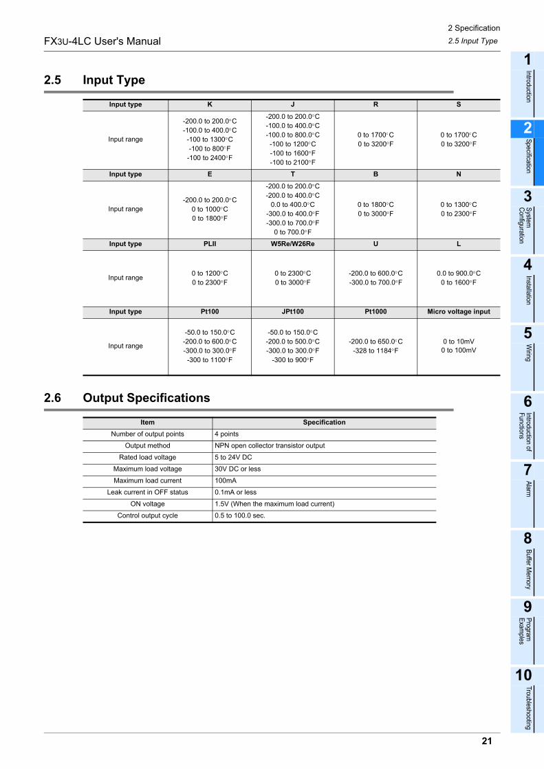
2.5 Input Type
2.6 Output Specifications
Input type K J R S
Input range
-200.0 to 200.0 C-100.0 to 400.0 C
-100 to 1300 C-100 to 800 F
-100 to 2400 F
-200.0 to 200.0 C-100.0 to 400.0 C-100.0 to 800.0 C-100 to 1200 C-100 to 1600 F-100 to 2100 F
0 to 1700 C0 to 3200 F
0 to 1700 C0 to 3200 F
Input type E T B N
Input range-200.0 to 200.0 C
0 to 1000 C0 to 1800 F
-200.0 to 200.0 C-200.0 to 400.0 C
0.0 to 400.0 C-300.0 to 400.0 F-300.0 to 700.0 F
0 to 700.0 F
0 to 1800 C0 to 3000 F
0 to 1300 C0 to 2300 F
Input type PLII W5Re/W26Re U L
Input range 0 to 1200 C0 to 2300 F
0 to 2300 C0 to 3000 F
-200.0 to 600.0 C-300.0 to 700.0 F
0.0 to 900.0 C0 to 1600 F
Input type Pt100 JPt100 Pt1000 Micro voltage input
Input range
-50.0 to 150.0 C-200.0 to 600.0 C-300.0 to 300.0 F-300 to 1100 F
-50.0 to 150.0 C-200.0 to 500.0 C-300.0 to 300.0 F
-300 to 900 F
-200.0 to 650.0 C-328 to 1184 F
0 to 10mV0 to 100mV
Item SpecificationNumber of output points 4 points
Output method NPN open collector transistor output
Rated load voltage 5 to 24V DC
Maximum load voltage 30V DC or less
Maximum load current 100mA
Leak current in OFF status 0.1mA or less
ON voltage 1.5V (When the maximum load current)
Control output cycle 0.5 to 100.0 sec.
21

3 System Configuration3.1 General ConfigurationFX3U-4LC User's Manual
3. System Configuration
3.1 General Configuration
*1. For the maximum number, refer to Section 3.2.
Component listPart name Model name Remarks
Temperature control block FX3U-4LC An FX2NC-CNV-IF or FX3UC-1PS-5V is necessary to connectthe 4LC with the FX3GC/FX3UC PLC.
PLC FX3G/FX3U/FX3GC/FX3UC PLC -
The special function block foran analog input/output FX3U-4AD,FX3U-4DA etc.
Special function block used for control using external inputs/outputs.For connectable equipment, refer to the following manualcorresponding to the connected PLC.
→ Refer to FX3G Hardware Edition.→ Refer to FX3U Hardware Edition.
→ Refer to FX3GC Hardware Edition.→ Refer to FX3UC Hardware Edition.
PC softwareGX Works2
PLC programming softwareGX Developer
PC - -
USB cable FX-USB-AW Cable with RS-422/USB converter between a FX PLC and PC.
RS-232C cable
F2-232CAB-1
PC connection cable and interfaceFX-232AWC-H
FX-422CAB0
FX3GC/FX3UC PLC
FX3G/FX3U PLCPC
GX Developer
USB cableRS-232C cable
Up to 8*1 can be connectedFX3U-4LC
Analog Input/analog outputspecial function blocks
FX2NC-CNV-IF or FX3UC-1PS-5V
22

3 System Configuration3.2 Applicable PLCFX3U-4LC User's Manual
1
Introduction
2
Specification
3
System
Configuration
4
Installation
5
Wiring
6
Introduction of Functions
7
Alarm
8
Buffer Mem
ory
9
Program
Examples
10
Troubleshooting
3.2 Applicable PLC
The version number can be checked by reading the last three digits of device D8001/D8101.*1. An FX2NC-CNV-IF or FX3UC-1PS-5V is necessary to connect the 4LC with the FX3GC/FX3UC PLC.
3.3 Connection with PLC
The 4LC connects with a PLC via an extension cable.The 4LC is handled as a special extension block of the PLC. The unit number of the 4LC is automaticallyassigned No.0 to No.7 (Unit No.1 to No.7 is assigned when the main unit is an FX3UC-32MT-LT(-2).) startingfrom the special function unit/block closest to the PLC main unit. (This unit number is used for the designation of a FROM/TO instruction.) For details on the assignment of the I/O number and unit number of the PLC, refer to the following manualcorresponding to the connected PLC.
→ Refer to FX3G Hardware Edition.→ Refer to FX3U Hardware Edition.
→ Refer to FX3GC Hardware Edition.→ Refer to FX3UC Hardware Edition.
• An FX2NC-CNV-IF or FX3UC-1PS-5V is necessary to connect the 4LC with the FX3GC/FX3UC PLC.• The number of I/O points occupied by the 4LC is eight. Make sure that the total number of I/O points
(occupied I/O points) of the main unit, extension unit(s), extension block(s) and the number of points occupied by special function blocks does not exceed the maximum number of I/O points of the PLC.For information on the maximum number of I/O points of the PLC, refer to the respective product manual.
→ Refer to FX3G Hardware Edition.→ Refer to FX3U Hardware Edition.
→ Refer to FX3GC Hardware Edition.→ Refer to FX3UC Hardware Edition.
Model name Applicability
FX3G Series PLC Ver. 1.00 and later(Up to 8 blocks can be connected)
FX3GC Series PLC Ver. 1.40 and later(Up to 6 blocks can be connected)
FX3U Series PLC Ver. 2.20 and later(Up to 8 blocks can be connected)
FX3UC Series PLC*1 Ver. 2.20 and later(Up to 6 blocks can be connected)
POWER
MOTOR-YSTARTDOGINT0INT1 A B
X-READYY-READYX-ERRORY-ERROR
STARTDOGINT0INT1 A B
MOTOR-X
FX3U-64CCL
POWER
RUNERR.RUNERR. SD RD
LL
Otherextensionunits/blocks
FX3U-4LC
FX3G/FX3U PLC FX3U-4LC
FX3GC/FX3UC PLC
FX2NC-CNV-IF
Otherextensionunits/blocks
23

4 Installation
FX3U-4LC User's Manual
4. Installation
The 4LC unit can be connected to the right side of the main unit, extension unit or extension block.To connect to an FX3GC/FX3UC PLC or FX2NC PLC extension block, the FX2NC-CNV-IF or FX3UC-1PS-5V isnecessary.For details, refer to the respective PLC manual.
→ Refer to FX3G Hardware Edition.→ Refer to FX3U Hardware Edition.
→ Refer to FX3GC Hardware Edition.→ Refer to FX3UC Hardware Edition.
The 4LC may be installed in a control cabinet with a 35mm wide DIN46277 DIN rail mounting or M4 screwdirect mounting.
Cautions in examining installing method
When the system is laid out in two stages, do not mount 4LC at the top of the second stage, or FX2N-CNV-BC cannot be installed directly.
INSTALLATION PRECAUTIONS
• Make sure to cut off all phases of the power supply externally before attempting installing.Failure to do so may cause electric shock or damage to the product.
INSTALLATION PRECAUTIONS
• Use the product within the generic environment specifications described in PLC main unit manual (Hardware Edition).Never use the product in areas with excessive dust, oily smoke, conductive dusts, corrosive gas (salt air, Cl2, H2S, SO2, or NO2),flammable gas, vibration or impacts, or expose it to high temperature, condensation, or rain and wind.If the product is used in such conditions, electric shock, fire, malfunctions, deterioration or damage may occur.
• Do not touch the conductive parts of the product directly. Doing so may cause device failures or malfunctions.
• Install the product securely using a DIN rail or mounting screws.• Install the product on a flat surface.
If the mounting surface is rough, undue force will be applied to the PC board, thereby causing nonconformities.• When drilling screw holes or wiring, make sure that cutting and wiring debris do not enter the ventilation slits.
Failure to do so may cause fire, equipment failures or malfunctions.• Be sure to remove the dust proof sheet from the PLC's ventilation port when installation work is completed.
Failure to do so may cause fire, equipment failures or malfunctions.• Connect extension cables securely to their designated connectors.
Loose connections may cause malfunctions.• Turn off the power to the PLC before attaching or detaching the following devices.
Failure to do so may cause device failures or malfunctions.- Peripheral devices, display modules, expansion boards and special adapters- I/O extension units/blocks, FX Series terminal block and the special function units/blocks- Battery and memory cassette
24

4 Installation4.1 DIN rail MountingFX3U-4LC User's Manual
1
Introduction
2
Specification
3
System
Configuration
4
Installation
5
Wiring
6
Introduction of Functions
7
Alarm
8
Buffer Mem
ory
9
Program
Examples
10
Troubleshooting
4.1 DIN rail Mounting
The product may be mounted on a 35mm wide DIN46277 (DIN rail).
1 Fit the upper edge (A in the figure to the right) of the DIN rail mounting groove onto the DIN rail.
2 Push the product onto the DIN rail.• An interval space of 1 to 2mm (0.04" to 0.08") between each unit is necessary.
3 Connect the extension cable.
Connect the extension cable (B in the figure to the right) tothe main unit, I/O extension unit/block or special functionunit/block on the left side of the product.For information on the extension cable connection procedure, refer to the respective product PLC manual.
→ Refer to FX3G Hardware Edition.→ Refer to FX3U Hardware Edition.
→ Refer to FX3GC Hardware Edition.→ Refer to FX3UC Hardware Edition.
• Example of installation on DIN rail- In the case of the FX3G/FX3U PLC
- In the case of the FX3GC/FX3UC PLC
B
FX3G/FX3U Seriesmain unit
DIN rail
FX3U-4LC
1 to 2mm(0.04" to 0.08")
Otherextensionequipment
1 to 2mm(0.04" to 0.08")
FX3GC/FX3UC Seriesmain unit
DIN rail
FX3U-4LC
1 to 2mm(0.04" to 0.08")
Otherextensionequipment
1 to 2mm(0.04" to 0.08")
FX2NC-CNV-IF orFX3UC-1PS-5V
25

4 Installation4.2 Direct MountingFX3U-4LC User's Manual
4.2 Direct Mounting
The product can be installed directly with screws.An interval space of 1 to 2mm (0.04" to 0.08") between each unit is necessary.For installation details, refer to the following respective PLC manual.
→ For mounting hole pitches, refer to Section 1.2.→ Refer to FX3G Hardware Edition.→ Refer to FX3U Hardware Edition.
→ Refer to FX3GC Hardware Edition.→ Refer to FX3UC Hardware Edition.
1 Create mounting holes in the mounting surface according to the external dimensions diagram.
2 Fit the 4LC (A in the figure to the right) to the mounting holes and tighten with M4 screws (B in the figure to the right).For the screw position and quantity, refer to the dimensioned drawing specified below.
→ For dimensions, refer to Section 1.2.
3 Connect the extension cable.
Connect the extension cable to the main unit, I/Oextension unit/block or special function unit/block onthe left side of the product. (Refer to Step 3 in Section 4.1.)For information on the extension cable connection procedure, refer to the respective PLC manual.
→ Refer to FX3G Hardware Edition.→ Refer to FX3U Hardware Edition.
→ Refer to FX3GC Hardware Edition.→ Refer to FX3UC Hardware Edition.
• Example of direct installation
FX3G/FX3U Seriesmain unit
FX3U-4LC
1 to 2mm(0.04" to 0.08")
Otherextensionequipment
1 to 2mm(0.04" to 0.08")
(+ shows the M4 screw)
26

5 Wiring
FX3U-4LC User's Manual
1
Introduction
2
Specification
3
System
Configuration
4
Installation
5
Wiring
6
Introduction of Functions
7
Alarm
8
Buffer Mem
ory
9
Program
Examples
10
Troubleshooting
5. Wiring
WIRING PRECAUTIONS
• Make sure to cut off all phases of the power supply externally before attempting wiring work.Failure to do so may cause electric shock or damage to the product.
WIRING PRECAUTIONS
• Connect the AC power supply to the dedicated terminals specified in this manual.If an AC power supply is connected to a DC input/output terminal or DC power supply terminal, the PLC will burn out.
• Do not wire vacant terminals externally.Doing so may damage the product.
• Use class D grounding (grounding resistance of 100 or less) with a wire of 2mm2 or thicker on the grounding terminal of the PLC.However, do not connect the ground terminal at the same point as a heavy electrical system.
• When drilling screw holes or wiring, make sure cutting or wire debris does not enter the ventilation slits.Failure to do so may cause fire, equipment failures or malfunctions.
• Make sure to observe the following precautions in order to prevent malfunctions under the influence of noise.- Do not bundle the power line or twisted shielded cable together with or lay it close to the main circuit, high-voltage line, or load line.
Otherwise, noise disturbance and/or surge induction are likely to take place. As a guideline, lay the control line at least 100mm (3.94") or more away from the main circuit, high-voltage line, or load line.
- Ground the shield wire or shield of the shielded cable at one point on the PLC. However, do not use common grounding with heavy electrical systems.
• Make sure to properly wire to the terminal blocks in accordance with the following precautions.Failure to do so may cause electric shock, equipment failures, a short-circuit, wire breakage, malfunctions, or damage to the product.- The disposal size of the cable end should follow the dimensions described in the manual.- Tightening torque should follow the specifications in the manual.
27

5 Wiring5.1 Power Supply WiringFX3U-4LC User's Manual
5.1 Power Supply Wiring
5.1.1 Power supply wiring
Power-on/off timing
The 4LC power supply should be turned ON simultaneously with or before the power supply of the PLC main unit. Before turning the power OFF, ensure the safety of the system and then simultaneously turn the main unit, 4LC, and other extension equipment (the special extension equipment is included) OFF.For details, refer to the respective PLC manual.
→ Refer to FX3G Hardware Edition.→ Refer to FX3U Hardware Edition.
→ Refer to FX3GC Hardware Edition.→ Refer to FX3UC Hardware Edition.
5.1.2 Grounding
Ground the cables as follows
• The grounding resistance should be 100 or less.• Independent grounding should be established whenever possible.
Independent grounding should be performed for best results.When independent grounding is not configured, perform "shared grounding" as shown in the following figure.For details, refer to the respective PLC manual.
→ Refer to FX3G Hardware Edition.→ Refer to FX3U Hardware Edition.
→ Refer to FX3GC Hardware Edition.→ Refer to FX3UC Hardware Edition.
• The grounding point should be close to the 4LC, and all grounding wires should be as short as possible.
FX3G/FX3U PLC [Main unit] 4LC
Stabilizedpower supply
24V DC
24-24+
Grounding(Ground resistance:
100Ω or less)
Grounding(Ground resistance:
100Ω or less)
FX3GC/FX3UC PLC[Main unit]
4LC
Stabilizedpower supply
24V DC
24-24+
FX2NC-CNV-IFor
FX3UC-1PS-5V
Grounding(Ground resistance:
100Ω or less)
Grounding(Ground resistance:
100Ω or less)
4LCOther
equipment
Shared groundingGood condition
Shared groundingNot allowed
Independent groundingBest condition
4LCOther
equipment4LC
Otherequipment
28

5 Wiring5.2 Input WiringFX3U-4LC User's Manual
1
Introduction
2
Specification
3
System
Configuration
4
Installation
5
Wiring
6
Introduction of Functions
7
Alarm
8
Buffer Mem
ory
9
Program
Examples
10
Troubleshooting
5.2 Input Wiring
5.2.1 Wiring example of thermocouple
For thermocouples applicable to the 4LC, refer to the following.→ Refer to the Section 2.4.
Caution
When using a thermocouple, use specified compensating lead wires.
5.2.2 Wiring example of resistance thermometer
For resistance thermometers applicable to the 4LC, refer to the following.→ Refer to the Section 2.4.
• When used the Pt100 (3-wire) or Pt1000 (3-wire)
Caution
When you use a resistance temperature sensor, the resistance of the leadwire is low, use a wire without a resistance difference between the leadwire.
FX3U-4LC
24V DC 24+
24-
TC-
TC+
FG
ThermocoupleCompensating
lead wire
Shielded cable
Grounding(Ground resistance:
100Ω or less)
FX3U-4LC
24V DC 24+
24-
PTB
PTA
PTB
FGShielded cable
Pt100 orPt1000
Grounding(Ground resistance:
100Ω or less)
29

5 Wiring5.2 Input WiringFX3U-4LC User's Manual
• When used the Pt1000 (2-wire)
Caution
• When you use a resistance temperature sensor, the resistance of the leadwire is low, use a wire without a resistance difference between the leadwire.
• Make sure to short-circuit the 'PTB' and 'PTB' terminals when 2-wire of a resistance thermometer sensor is input.
5.2.3 Wiring example of micro voltage input
For the input range of micro voltage inputs applicable to the 4LC, refer to the following.→ Refer to the Section 2.5.
FX3U-4LC
24V DC 24+
24-
PTB
PTA
PTB
FG
Shielded cable
Pt1000
Grounding(Ground resistance:
100Ω or less)
FX3U-4LC
24V DC 24+
24-
COM
VL+
FGShielded cable
Voltage input
Grounding(Ground resistance:
100Ω or less)
30
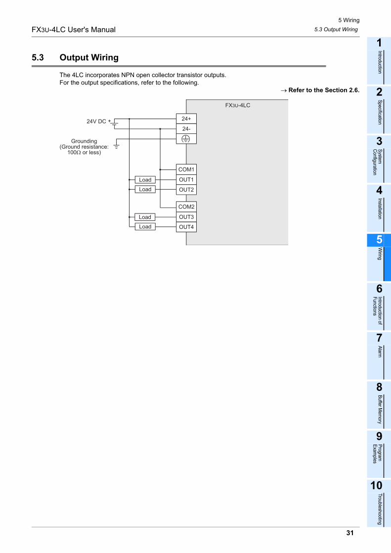
5 Wiring5.3 Output WiringFX3U-4LC User's Manual
1
Introduction
2
Specification
3
System
Configuration
4
Installation
5
Wiring
6
Introduction of Functions
7
Alarm
8
Buffer Mem
ory
9
Program
Examples
10
Troubleshooting
5.3 Output Wiring
The 4LC incorporates NPN open collector transistor outputs.For the output specifications, refer to the following.
→ Refer to the Section 2.6.
FX3U-4LC
24V DC 24+
24-
OUT1
COM1
OUT2
OUT3
COM2
OUT4
Load
Load
Load
Load
Grounding(Ground resistance:
100Ω or less)
31

5 Wiring5.4 Terminal Screw and Tightening TorqueFX3U-4LC User's Manual
5.4 Terminal Screw and Tightening Torque
The terminals on the 4LC use M3 screws.Refer to the figures below for cable end treatment.Tighten the terminals to a torque of 0.5 to 0.8 N•m.Do not tighten terminal screws exceeding the specified torque. Failure to do so may cause equipment failuresor malfunctions.
• When one wire is connected to one terminal
• When two wires are connected to one terminal
TerminalTerminal
Terminalscrew
Crimpterminal
6.2mm(0.24")
or less
3.2(0.13")
6.2mm(0.24")
or less
3.2(0.13")
Terminalscrew
Crimpterminal
Terminal
6.2mm(0.24")
or less
3.2(0.13")
6.3mm(0.25")
or more
6.2mm(0.24")
or less
3.2(0.13")
6.3mm(0.25")
or more
32

6 Introduction of Functions6.1 Functions ListFX3U-4LC User's Manual
1
Introduction
2
Specification
3
System
Configuration
4
Installation
5
Wiring
6
Introduction of Functions
7
Alarm
8
Buffer Mem
ory
9
Program
Examples
10
Troubleshooting
6. Introduction of Functions
6.1 Functions List
The list below describes functions of the 4LC.Functions Description Reference
Control mode switch function Selects the control type and used input/output for each control group. Section 6.2
Transistor output selection function Selects the function of transistor outputs built into the 4LC. Section 6.3
PID control Offers stable control results by presetting constants, P (proportional band), I (integral time) and D (derivative time). Section 6.4
Overshoot prevention function Prevents overshoot of the control output (MV). Subsection 6.4.2
Two-position control Turns ON or OFF the control output (MV) depending on whether the measuredvalue (PV) is larger or smaller than the set value (SV). Section 6.5
Heating/cooling PID control Handles two systems of outputs, heating control output and cooling controloutput. Section 6.6
Overlap/Dead band function Switches the significant point between control stability and energy saving byshifting the temperature at which cooling control is started.
Subsection 6.6.3
Cooling method Switches the cooling method (among "air cooling type", "water cooling type"and "cooling gain linear type") in accordance with the cooling unit type.
Subsection 6.6.4
Cascade control Performs cascade control by combining two control loops, the master loop andslave loop. Section 6.7
SV tracking selection functionMakes the slave channel set value (SV) track the set value (value stored in theset value monitor buffer memory) just before changeover to cascade OFF whenthe cascade control function is changed from ON to OFF.
Subsection 6.7.3
Auto tuning function Automatically measures, calculates and sets optimal PID constants for thepreset temperature. Section 6.8
AT (Auto tuning) biasChanges the auto tuning set value (SV).Set to prevent the measured value (PV) from exceeding the set value (SV)when performing auto tuning.
Subsection 6.8.2
Startup tuning functionAutomatically calculates and sets PID constants based on the responsecharacteristics of the control target when control is started or when the setvalue (SV) is changed.
Section 6.9
AUTO mode/MANUAL modeSwitches the mode between the AUTO mode (in which the control output value(MV) is automatically calculated based on the set value (SV)) and the MANUALmode (in which the control output value (MV) is set arbitrarily and manually).
Section 6.10
Balance-less, bump-less function Prevents overload caused by drastic change in the control output (MV) whenthe mode is changed over between the AUTO mode and the MANUAL mode.
Subsection 6.10.2
Heater disconnection alarm function Detects the current flowing using the current detector (CT), and detects heaterdisconnection. Section 6.11
Number of times of heater disconnectionalarm delay
Sets the continuous number of times of detecting a heater disconnection ordetecting abnormal current while the output is OFF to be judged as an alarm.
Subsection 6.11.2
Loop breaking alarm function Detects abnormalities in the control target, input sensors, etc. Section 6.12
Loop breaking alarm dead zone Sets the area to be excluded from the loop breaking alarm status. Subsection 6.12.2
33

6 Introduction of Functions6.2 Control Mode Switch FunctionFX3U-4LC User's Manual
6.2 Control Mode Switch Function
The control mode switch function sets the control type (PID control, two-position control, manual control,cascade control or heating/cooling control) and used input/output (external or internal) for each control group.Make sure to set the control mode before performing control.Up to 4 loops are available for each control type. However, only up to 2 loops are available for cascadecontrol.Control groups are classified into the group 1 (CH1 and CH2) and group 2 (CH3 and CH4).
Control mode
• When internal input is selectedThe 4LC performs control using measured values detected through inputs built into the 4LC.
• When external input is selectedThe 4LC performs control using values stored in external input value buffer memories (BFM#25 to BFM#28) without using inputs built into the 4LC.
• When internal output is selectedThe 4LC performs control using transistor outputs built into the 4LC. However, in heating/cooling PID control, the control output of CH2 and CH4 should use an external output.
• When external output is selectedThe 4LC performs control using values stored in external output value monitor/heating external output value monitor buffer memories (BFM#32 to BFM#35) and cooling external output value monitor buffer memories (BFM#36 to BFM#39) without using transistor outputs built into the 4LC. The transistor output built into the 4LC is controllable when transistor output selections 1 and 2 are chosen. Additionally the outputs can also be used as alarm outputs.
→ For details on the external input value, refer to Subsection 8.2.8.→ For details on the external output value, refer to Subsection 8.2.11 or 8.2.12.
→ For details on the transistor output selection, refer to Subsection 8.2.50.
Control mode Control type Input Output0 PID control
Two-position controlManual control
Cascade control
InternalInternal
1 External
2 InternalExternal
3 External
4Heating/cooling PID
controlTwo-position control
InternalInternal
5 External
6 InternalExternal
7 External
34

6 Introduction of Functions6.2 Control Mode Switch FunctionFX3U-4LC User's Manual
1
Introduction
2
Specification
3
System
Configuration
4
Installation
5
Wiring
6
Introduction of Functions
7
Alarm
8
Buffer Mem
ory
9
Program
Examples
10
Troubleshooting
Point
When external input is selected, the following results are given.• Input range setting
- The input span is "external input range upper limit"-"external input range lower limit".- The input range is from "external input range lower limit" to "external input range upper limit".
• Setting limiter- The setting range of the setting limiter upper limit is from "setting limiter lower limit +1" to "external input
range upper limit".- The setting range of the setting limiter lower limit is from "external input range lower limit" to "setting
limiter upper limit -1".• Set value (SV)
- The set value range is from "setting limiter lower limit" to "setting limiter upper limit".• Input error
- When a value equivalent to or larger than "external input range upper limit +5%/input span" is set to the external input value, it is regarded as an input error (upper limit), and b0 of the event buffer memory for the corresponding channel turns ON.
- When a value equivalent to or smaller than "external input range lower limit -5%/input span" is set to the external input value, it is regarded as an input error (lower limit), and b1 of the event buffer memory for the corresponding channel turns ON.
When external output is selected, the following results are given• External output value/heating external output value and cooling external output value
- The control output value is written to the external output value/heating external output value and cooling external output value, and the scaled value is written to the range from "external output range lower limit" to "external output range upper limit" without regard to the setting of the control mode switch function.
Associated buffer memory
Caution
It is not possible to change the control mode while control is being performed. If the control mode is changed while control is being performed, the contents of setting are changed when control is stopped.
BFM No.Description Reference
CH1 CH2 CH3 CH4
#1 #2 #3 #4Event(b0 : Input error (upper limit))(b1 : Input error (lower limit))
Subsection 8.2.2
#5 #6 #7 #8 Measured value (PV) Subsection 8.2.3
#25 #26 #27 #28 External input value Subsection 8.2.8
#32 #33 #34 #35 External output value/Heating external output value monitor Subsection 8.2.11
#36 #37 #38 #39 Cooling external output value monitor Subsection 8.2.12
#44 #45 #46 #47 Control mode monitor Subsection 8.2.14
#48 #88 #128 #168 Set value (SV) Subsection 8.2.15
#76 #116 #156 #196 Setting limiter upper limit Subsection 8.2.40
#77 #117 #157 #197 Setting limiter lower limit Subsection 8.2.41
#82 #122 #162 #202 External input range upper limit Subsection 8.2.46
#83 #123 #163 #203 External input range lower limit Subsection 8.2.47
#84 #124 #164 #204 External output range upper limit Subsection 8.2.48
#85 #125 #165 #205 External output range lower limit Subsection 8.2.49
#86 #126 #166 #206 Transistor output selection Subsection 8.2.50
#240 #241 Control mode switch Subsection 8.2.62
35

6 Introduction of Functions6.3 Transistor Output Selection FunctionFX3U-4LC User's Manual
6.3 Transistor Output Selection Function
The transistor output selection function selects either one among control output, alarm output and loopbreaking alarm output for transistor outputs built into the 4LC.For example, when external outputs are used for control, transistor outputs built into the 4LC are not required,and can be used as alarm outputs.The transistor output selection function varies depending on the control mode setting as shown below.Set the transistor output for each channel.
→ For details on the control mode switch, refer to Section 6.2.
Transistor output selection
*1. When selecting control mode "4" or "5", use external output for CH2 and CH4.
Caution
It is not possible to change the setting while control is being performed. If the setting is changed while control is being performed, the contents of setting are reflected when control is stopped.
Transistor output
selection set value
Control mode [BFM#240 (CH1, CH2), BFM#241 (CH3, CH4)]
0, 1 : PID control(Internal output)
2, 3 : PID control(External output)
4, 5 : Heating/cooling PID control
(Internal output)*1
6, 7 : Heating/cooling PID control
(External output)
0
OUT1 CH1 control output Normally OFF CH1 heating control output Normally OFF
OUT2 CH2 control output Normally OFF CH1 cooling control output Normally OFF
OUT3 CH3 control output Normally OFF CH3 heating control output Normally OFF
OUT4 CH4 control output Normally OFF CH3 cooling control output Normally OFF
1
OUT1 CH1 control output CH1 control output CH1 heating control output CH1 heating control output
OUT2 CH2 control output CH2 control output CH1 cooling control output CH2 heating control output
OUT3 CH3 control output CH3 control output CH3 heating control output CH3 heating control output
OUT4 CH4 control output CH4 control output CH3 cooling control output CH4 heating control output
2
OUT1 CH1 control output CH1 control output CH1 heating control output CH1 cooling control output
OUT2 CH2 control output CH2 control output CH1 cooling control output CH2 cooling control output
OUT3 CH3 control output CH3 control output CH3 heating control output CH3 cooling control output
OUT4 CH4 control output CH4 control output CH3 cooling control output CH4 cooling control output
3
OUT1 CH1 control output CH1 alarm 1 state CH1 heating control output CH1 alarm 1 state
OUT2 CH2 control output CH2 alarm 1 state CH1 cooling control output CH2 alarm 1 state
OUT3 CH3 control output CH3 alarm 1 state CH3 heating control output CH3 alarm 1 state
OUT4 CH4 control output CH4 alarm 1 state CH3 cooling control output CH4 alarm 1 state
4
OUT1 CH1 control output CH1 alarm 2 state CH1 heating control output CH1 alarm 2 state
OUT2 CH2 control output CH2 alarm 2 state CH1 cooling control output CH2 alarm 2 state
OUT3 CH3 control output CH3 alarm 2 state CH3 heating control output CH3 alarm 2 state
OUT4 CH4 control output CH4 alarm 2 state CH3 cooling control output CH4 alarm 2 state
5
OUT1 CH1 control output CH1 alarm 3 state CH1 heating control output CH1 alarm 3 state
OUT2 CH2 control output CH2 alarm 3 state CH1 cooling control output CH2 alarm 3 state
OUT3 CH3 control output CH3 alarm 3 state CH3 heating control output CH3 alarm 3 state
OUT4 CH4 control output CH4 alarm 3 state CH3 cooling control output CH4 alarm 3 state
6
OUT1 CH1 control output CH1 alarm 4 state CH1 heating control output CH1 alarm 4 state
OUT2 CH2 control output CH2 alarm 4 state CH1 cooling control output CH2 alarm 4 state
OUT3 CH3 control output CH3 alarm 4 state CH3 heating control output CH3 alarm 4 state
OUT4 CH4 control output CH4 alarm 4 state CH3 cooling control output CH4 alarm 4 state
7
OUT1 CH1 control output CH1 loop breaking alarm state CH1 heating control output Normally OFF
OUT2 CH2 control output CH2 loop breaking alarm state CH1 cooling control output Normally OFF
OUT3 CH3 control output CH3 loop breaking alarm state CH3 heating control output Normally OFF
OUT4 CH4 control output CH4 loop breaking alarm state CH3 cooling control output Normally OFF
36

6 Introduction of Functions6.3 Transistor Output Selection FunctionFX3U-4LC User's Manual
1
Introduction
2
Specification
3
System
Configuration
4
Installation
5
Wiring
6
Introduction of Functions
7
Alarm
8
Buffer Mem
ory
9
Program
Examples
10
Troubleshooting
Associated buffer memoryBFM No.
Description ReferenceCH1 CH2 CH3 CH4
#1 #2 #3 #4Event(b4 to b7 Alarm 1 to Alarm 4)(b8 Loop breaking alarm)
Subsection 8.2.2
#9 #10 #11 #12 Control output value (MV) monitor/Heating control output value (MV) monitor Subsection 8.2.4
#13 #14 #15 #16 Cooling control output value (MV) monitor Subsection 8.2.5
#17 #18 #19 #20 Control output flag Subsection 8.2.6
#86 #126 #166 #206 Transistor output selection Subsection 8.2.50
#240 #241 Control mode switch Subsection 8.2.62
37

6 Introduction of Functions6.4 PID controlFX3U-4LC User's Manual
6.4 PID control
6.4.1 Easy PID control with two degrees of freedom
PID control is a control method to obtain stable control result by setting each of the constants "P (proportionalband)", "I (integral time)" and "D (derivative time)".However, if each PID constant is so set that the "response to setting" becomes good, the "response todisturbance" becomes deteriorated in PID control.On the contrary, if each PID constant is so set that the "response to disturbance" becomes good, the"response to setting" becomes deteriorated.The 4LC performs easy PID control with two degrees of freedom in which PID constants realizing goodresponse to disturbance are adopted and the shape of the "response to setting" can be selected as either"fast", "medium" or "slow".Select "fast", "medium" or "slow" using the control response parameter.Select control mode "0" to "3" for performing PID control.
→ For details on the control mode switch, refer to Section 6.2.
Conventional PID control• When PID constants are set so that the response to changes in set value becomes good
• When PID constants are so set that the response to disturbance becomes good
Easy PID control with two degrees of freedom
Response to changes in set value (SV) Response to disturbance
Set value (SV) Set value (SV)
Response to changes in set value (SV) Response to disturbance
Set value (SV) Set value (SV)
Response to changes in set value (SV) Response to disturbance
Set value (SV) Set value (SV)
Fast
Medium
Slow
38

6 Introduction of Functions6.4 PID controlFX3U-4LC User's Manual
1
Introduction
2
Specification
3
System
Configuration
4
Installation
5
Wiring
6
Introduction of Functions
7
Alarm
8
Buffer Mem
ory
9
Program
Examples
10
Troubleshooting
Associated buffer memory
6.4.2 Overshoot prevention function
When a deviation continues for a long time, the PID arithmetic operation result exceeds the effective range ofthe control output. At this time, even if the deviation becomes smaller, it takes some time until the outputcomes within the effective range because of the integral operation. As a result, execution of an actualcorrection operation is delayed, and overshoot/undershoot occurs.In order to prevent overshoot, the 4LC is equipped with the RFB (reset-feedback) limiter function.The RFB limiter function feeds back the excessive quantity to the integral value and makes the arithmeticoperation result be held at the limit point when the PID arithmetic operation result exceeds the limit point(upper/lower limit of the output limiter) so that the PID arithmetic operation result always remains inside theeffective range. Accordingly, when a deviation becomes small, the correction operation is immediatelyperformed.The RFB limiter function is automatically activated while PID control is performed, and does not requiresetting.
Operation
BFM No.Description Reference
CH1 CH2 CH3 CH4#58 #98 #138 #178 Proportional band (P)/Heating proportional band (P) Subsection 8.2.22
#60 #100 #140 #180 Integral time (I) Subsection 8.2.24
#61 #101 #141 #181 Derivative time (D) Subsection 8.2.25
#62 #102 #142 #182 Control response parameter Subsection 8.2.26
#64 #104 #144 #184 Output limiter upper limit/Heating upper output limiter Subsection 8.2.28
#65 #105 #145 #185 Output limiter lower limit Subsection 8.2.29
#67 #107 #147 #187 Output change ratio limiter Subsection 8.2.31
#240 #241 Control mode switch Subsection 8.2.62
(When the RFB limiter function is not provided)
Control output
(When the RFB limiter function is provided)
Temperature
Large overshoot
Control output
Output limiter upper limit
The excessive quantity above the output limiterupper limit is fed back to the integral value, andthe arithmetic operation result is held at theupper limit value.
Temperature
Set value(SV)
Set value(SV)
Output limiter upper limit
Output limiter lower limitOutput limiter lower limit
39

6 Introduction of Functions6.5 Two-position ControlFX3U-4LC User's Manual
6.5 Two-position Control
When the proportional band (P) or heating proportional band (P) value is set to "0", the 4LC performs two-position control.In two-position control, the control output (MV) is set to ON when the measured value (PV) is larger than theset value (SV) or OFF when the measured value (PV) is smaller than the set value (SV).When the adjustment sensitivity (dead zone) is set, repetitious turning ON/OFF of the output around the setvalue (SV) can be prevented.However, if the adjustment sensitivity (dead zone) is set to a large value, upward/downward fluctuationbecomes large accordingly. If the adjustment sensitivity (dead zone) is set to a small value, chattering may becaused by small oscillations of measured values (PV).Select control mode "0" to "7" for performing two-position control.
→ For details on the control mode switch, refer to Section 6.2.
Operation
Associated buffer memoryBFM No.
Description ReferenceCH1 CH2 CH3 CH4
#9 #10 #11 #12 Control output value (MV) monitor/Heating control output value (MV) monitor Subsection 8.2.4
#13 #14 #15 #16 Cooling control output value (MV) monitor Subsection 8.2.5
#48 #88 #128 #168 Set value (SV) Subsection 8.2.15
#58 #98 #138 #178 Proportional band (P)/Heating proportional band (P) Subsection 8.2.22
#69 #109 #149 #189 Adjustment sensitivity (dead zone) setting Subsection 8.2.23
#240 #241 Control mode switch Subsection 8.2.62
Set value (SV)
Control output (MV) ON OFF ON OFFTime
The adjustment sensitivity (dead zone) isequally given to the upper portion and thelower portion of the set value (SV).
Adjustment sensitivity (dead zone)
40

6 Introduction of Functions6.6 Heating/cooling PID controlFX3U-4LC User's Manual
1
Introduction
2
Specification
3
System
Configuration
4
Installation
5
Wiring
6
Introduction of Functions
7
Alarm
8
Buffer Mem
ory
9
Program
Examples
10
Troubleshooting
6.6 Heating/cooling PID control
6.6.1 Heating/cooling PID control
Heating/cooling PID control handles two systems of outputs, heating control output and cooling controloutput.The heating side performs the reverse operation in which the control output (MV) decreases as the measuredvalue (PV) increases, and the cooling side performs the normal operation in which the control output (MV)increases as the measured value (PV) increases.With regard to PID constants for heating/cooling control, set the proportional band (P) respectively for each ofthe heating side and the cooling side, and set a common value to the integral time (I) and derivative time (D)for both the heating side and the cooling side.It means that the 4LC performs arithmetic operation using four PID constants, proportional band for theheating side, proportional band for the cooling side, common integral time and common derivative time.It is possible to provide the dead band and overlap area at the point at which heating control and coolingcontrol switch each other.Select control mode "4" to "7" for performing heating/cooling PID control.
→ For details on the overlap/dead band, refer to Subsection 6.6.3.→ For details on the control mode switch, refer to Section 6.2.
Operation
Associated buffer memoryBFM No.
Description ReferenceCH1 CH2 CH3 CH4
#9 #10 #11 #12 Control output value (MV) monitor/Heating control output value (MV) monitor Subsection 8.2.4
#13 #14 #15 #16 Cooling control output value (MV) monitor Subsection 8.2.5
#58 #98 #138 #178 Proportional band (P)/Heating proportional band (P) Subsection 8.2.22
#59 #99 #139 #179 Cooling proportional band (P) Subsection 8.2.23
#60 #100 #140 #180 Integral time (I) Subsection 8.2.24
#61 #101 #141 #181 Derivative time (D) Subsection 8.2.25
#62 #102 #142 #182 Control response parameter Subsection 8.2.26
#63 #103 #143 #183 Overlap/Dead band Subsection 8.2.27
#64 #104 #144 #184 Output limiter upper limit/Heating upper output limiter setting Subsection 8.2.28
#66 #106 #146 #186 Cooling upper output limiter setting Subsection 8.2.30
#70 #110 #150 #190 Control output cycle setting/Heating control output period setting Subsection 8.2.34
#71 #111 #151 #191 Cooling control output period setting Subsection 8.2.35
#232 Cooling method setting Subsection 8.2.54
#240 #241 Control mode switch Subsection 8.2.62
100%
0%
Heating output value
Heatingproportional
band
Coolingproportional
band
Measuredvalue (PV)
Set value(SV)
Cooling output value
Control output value (MV)
41

6 Introduction of Functions6.6 Heating/cooling PID controlFX3U-4LC User's Manual
Caution
• Cascade control is disabled when heating/cooling PID control is selected.• The loop breaking alarm function is disabled in heating/cooling PID control.• The loop breaking alarm dead zone is invalid in heating/cooling PID control.• The MANUAL mode is not available in heating/cooling PID control.• The output limiter lower limit is invalid in heating/cooling PID control.
6.6.2 Overshoot prevention function
The overshoot prevention function is enabled in heating/cooling PID control.→ For details on the Overshoot prevention function, refer to Subsection 6.4.2.
42

6 Introduction of Functions6.6 Heating/cooling PID controlFX3U-4LC User's Manual
1
Introduction
2
Specification
3
System
Configuration
4
Installation
5
Wiring
6
Introduction of Functions
7
Alarm
8
Buffer Mem
ory
9
Program
Examples
10
Troubleshooting
6.6.3 Overlap/dead band function
The overlap/dead band function switches the significant point between control stability and energy saving byshifting the temperature at which cooling control is started.
OverlapThe overlap area indicates the temperature area where both heating output and cooling output are given.Control stability is improved in the overlap area where the temperature change caused by outputs is smalldue to trade-off between two outputs.For setting the overlap area, set a negative value to the overlap/dead band buffer memory.
Operation example 1 (When the overlap area is set)
Dead bandThe dead band is located between the proportional band on the heating side and the proportional band on thecooling side. Both the control output on the heating side and the control output on the cooling side are notoutput when the measured value (PV) is located in the dead band. As a result, the energy-saving effect isgiven.For setting the dead band, set a positive value to the overlap/dead band buffer memory.
Operation example 2 (When the dead band is set)
100%
0%
Heating output value
Control output value (MV) Heatingpropor-tionalband
Coolingproportional
band
Measuredvalue (PV)
Set value(SV)
Overlap
Cooling output value
100%
0%
Heating output value
Heatingproportional
band
Coolingproportional
band
Measuredvalue (PV)
Set value(SV)
Deadband
Cooling output value
Control output value (MV)
43

6 Introduction of Functions6.6 Heating/cooling PID controlFX3U-4LC User's Manual
Associated buffer memory
Caution
• The overlap/dead band buffer memories are invalid in two-position control.• The overlap/dead band buffer memories store "0" in PID control.• Set the overlap area within the proportional band.
6.6.4 Cooling method
This function switches the cooling method (among "air cooling type", "water cooling type" and "cooling gainlinear type") in accordance with the cooling unit type for heating/cooling PID control.Because cooling characteristics are considerably different between the air cooling method and the watercooling method, PID constants suitable to the cooling unit can be obtained by auto tuning if the correct coolingmethod is selected.
Air cooling type/water cooling typeThe adopted algorithm postulates heating/cooling control for plastic molding machines.This algorithm offers good response to the set value also in units having a cooling mechanism with nonlinearcharacteristics, and achieves response characteristics to the set value with a small overshoot.
Cooling gain linear typeThe adopted algorithm postulates for applications without nonlinear cooling capacity.An algorithm is used for applications without nonlinear cooling capacity such as an electronic cooler using aPeltier device is adopted.
Associated buffer memory
Caution
Set this buffer memory before performing auto tuning because the setting affects arithmetic operation results of PID constants acquired by auto tuning.
BFM No.Description Reference
CH1 CH2 CH3 CH4#58 #98 #138 #178 Proportional band (P)/Heating proportional band (P) Subsection 8.2.22
#59 #99 #139 #179 Cooling proportional band (P) Subsection 8.2.23
#63 #103 #143 #183 Overlap/Dead band Subsection 8.2.27
BFM No.Description Reference
CH1 CH2 CH3 CH4#232 Cooling method setting Subsection 8.2.54
44

6 Introduction of Functions6.7 Cascade controlFX3U-4LC User's Manual
1
Introduction
2
Specification
3
System
Configuration
4
Installation
5
Wiring
6
Introduction of Functions
7
Alarm
8
Buffer Mem
ory
9
Program
Examples
10
Troubleshooting
6.7 Cascade control
6.7.1 Cascade control
Cascade control combines master channel control and slave channel control into one control loop.Cascade control is suitable for situations where there is a large time delay between the temperature near aheat source and the temperature of the object to be controlled.The master channel performs PID arithmetic operation using the measured value (PV) of the control target oran external input value as the input, converts the control output into the cascade signal using the cascadebias and cascade gain, and then corrects the set value (SV) of the slave channel.The slave channel performs PID control using the set value (SV) converted into the cascade signal.Up to 2 control loops are available in the 4LC.Set the control mode to "0" to "3" for performing cascade control.The combination of available master channel and slave channel is determined for each control loop as shownbelow.
→ For details on the control mode switch, refer to Section 6.2.
Cascade control block diagram (reference) This diagram shows an example of the control loop 1.
Control loop Master channel Slave channel Control output1 Channel 1 Channel 2 OUT2
2 Channel 3 Channel 4 OUT4
Cascade ON
Cascade OFF
PID arithmeticoperation
Set value monitor
Set value monitor
Measured value (PV)or
External input value
Set value (SV)
+
-
Measured value (PV)or
External input value
Set value (SV) Cascade gain
Cascade monitor
Cascade bias
+
+ +
-
Control outputOUT 1
Control outputOUT 2
Master channel side (channel 1)
Slave channel side (channel 2)
PID arithmeticoperation
Control loop1
Control output (MV)
Control output (MV)
45

6 Introduction of Functions6.7 Cascade controlFX3U-4LC User's Manual
Conditions for enabling cascade control
• The master channel is separated from the slave channel, and the proper intermediate control quantity can be selected.
• The response speed of the control target in the slave channel is sufficiently faster than the response speed of the control target in the master channel.
Associated buffer memory
Caution
• Cascade control is enabled only when PID control is selected. (Cascade control is also enabled also in the MANUAL mode.)
• Auto tuning and startup tuning are disabled while cascade control is being performed.• The alarm waiting operation is disabled on the slave channel side when the set value (SV) is changed.
BFM No.Description Reference
CH1 CH2 CH3 CH4#5 #6 #7 #8 Measured value (PV) Subsection 8.2.3
#9 #10 #11 #12 Control output value (MV) monitor/Heating control output value (MV) monitor Subsection 8.2.4
#25 #26 #27 #28 External input value Subsection 8.2.8
#40 #41 #42 #43 Set value monitor Subsection 8.2.13
#44 #45 #46 #47 Control mode monitor Subsection 8.2.14
#48 #88 #128 #168 Set value (SV) Subsection 8.2.15
#58 #98 #138 #178 Proportional band (P)/Heating proportional band (P) Subsection 8.2.22
#60 #100 #140 #180 Integral time (I) Subsection 8.2.24
#61 #101 #141 #181 Derivative time (D) Subsection 8.2.25
#62 #102 #142 #182 Control response parameter Subsection 8.2.26
#240 #241 Control mode switch Subsection 8.2.62
#242 #243 SV tracking selection Subsection 8.2.63
#244 #245 Cascade ON/OFF Subsection 8.2.64
#246 #247 Cascade gain Subsection 8.2.65
#248 #249 Cascade bias Subsection 8.2.66
#250 #251 Cascade monitor Subsection 8.2.67
46

6 Introduction of Functions6.7 Cascade controlFX3U-4LC User's Manual
1
Introduction
2
Specification
3
System
Configuration
4
Installation
5
Wiring
6
Introduction of Functions
7
Alarm
8
Buffer Mem
ory
9
Program
Examples
10
Troubleshooting
6.7.2 Tuning during cascade control
Auto tuning and startup tuning are disabled while cascade control is being performed.Perform tuning in advance while cascade control is OFF, and then set PID constants regarded asapproximate values.Perform tuning respectively for each channel, and stop control of the channel where tuning is not performed(by setting the operation mode to "0 : Unused", "1 : Monitor" or "2 : Monitor + Alarm").Example of tuning procedure 1) Turn ON control of only the slave channel, perform auto tuning, and obtain PID constants for the slave
channel.Set the operation mode of the master channel to "1 : Monitor" or "2 : Monitor + Alarm", and the controloutput should only be wired to a slave channel.
Point
When both the master channel and the slave channel mainly perform PID control in cascade control, theintegral operation is performed in each channel, the low frequency gain increases too much, and anoscillating low-frequency response may occur.Accordingly, it is generally recommended to avoid the above phenomenon by selecting P control (I = 0, D= 0) or PD control (I = 0) for the slave channel.Determine P control constants or PD control constants based on the auto tuning result performed in theslave channel, and reduce the proportional band by 60 to 70%.
2) Turn ON control of only the master channel, perform auto tuning, and obtain PID constants for the masterchannel.Set the operation mode of the slave channel to "1 : Monitor" or "2 : Monitor + Alarm", and the controloutput should only be wired to a master channel.
3) Set a same set value (SV) for both the master channel and the slave channel.4) Turn OFF cascade control, and control only the slave channel.
Set the operation mode of the master channel to "1 : Monitor" or "2 : Monitor + Alarm", and the controloutput should only be wired to a slave channel.
5) When the measured value (PV) becomes stable in both the master channel and the slave channel, obtainthe measured value (PV) difference En between the master channel and the slave channel.
En = Measured value (PV) of master channel - Measured value (PV) of slave channel6) The span of the set value monitor of a slave channel is determined to be about 4 times of the measured
value (PV) difference En of the master channel from Procedure 5) and slave channel, the cascade gain isset up as follows.
7) Cascade bias is set up as follows.
8) The set value (SV) of the slave channel is set up as follows. After the measured value (PV) becomesstable in both the master channel and the slave channel.
9) Set the operation mode of the master channel to "3 : Monitor + Alarm + Control", and perform cascadecontrol (cascade ON).While checking the control status, manually adjust PID constants for the master channel.The control output should only be wired to a master channel.
Input span of slave channelCascade gain = - (number of times)
Span of the set value monitor of slave channelNormal operation :
Input span of slave channel(number of times)
Span of the set value monitor of slave channelReverse operation :
Cascade gain = +
Input span of slave channel100 (%)
Span of the set value monitor of slave channel / 2Normal operation :
×Cascade bias = +
Input span of slave channel100 (%)
Span of the set value monitor of slave channel / 2Reverse operation :
×Cascade bias = -
Set value (SV) of the slave channel = En - Set value (SV) of master channel (SV)Normal operation :
Set value (SV) of the slave channel = Set value (SV) of master channel (SV) - EnReverse operation :
47

6 Introduction of Functions6.7 Cascade controlFX3U-4LC User's Manual
6.7.3 SV tracking selection function
The SV tracking selection function makes the slave channel set value (SV) track the set value (value stored inthe set value monitor buffer memory) just before changeover to cascade OFF when the cascade controlfunction is changed from ON to OFF.Control group 1 (GR1) : The setting is applied to CH1 and CH2.Control group 2 (GR2) : The setting is applied to CH3 and CH4.
Example of operation 1 (When SV tracking is provided)
Example of operation 2 (When SV tracking is not provided)
Associated buffer memory
Point
This function prevents drastic change in the set value (SV) caused when the cascade control function is changed from ON to OFF.
BFM No.Description Reference
CH1 CH2 CH3 CH4#40 #41 #42 #43 Set value monitor Subsection 8.2.13
#48 #88 #128 #168 Set value (SV) Subsection 8.2.15
#242 #243 SV tracking selection Subsection 8.2.63
#244 #245 Cascade ON/OFF Subsection 8.2.64
Cascade controlON -> OFF changeover point
Time
Set value (SV) of slavechannel Value stored in set
value monitor buffermemory for slavechannel
Cascade controlON -> OFF changeover point
Time
Set value (SV) of slavechannel
Value stored in setvalue monitor buffermemory for slavechannel
48

6 Introduction of Functions6.8 Auto Tuning FunctionFX3U-4LC User's Manual
1
Introduction
2
Specification
3
System
Configuration
4
Installation
5
Wiring
6
Introduction of Functions
7
Alarm
8
Buffer Mem
ory
9
Program
Examples
10
Troubleshooting
6.8 Auto Tuning Function
6.8.1 AT (Auto tuning)
The auto tuning function automatically measures, calculates and sets optimal PID constants in accordancewith the set temperature.The auto tuning function is available in PID control and heating/cooling PID control.Write "1" to the AT execution command buffer memory to perform auto tuning.When auto tuning starts, two-position control is performed using the set value (SV). By two-position control,the output is forcedly hunted and its amplitude and oscillation cycle are measured. PID constants arecalculated based on the measured values, and stored in each buffer memory.The buffer memories shown below store calculated values.
When auto tuning finishes normally, control continues with new calculated PID constants.The AT bias can be set for auto tuning.
Example of operation (When AT is performed while the temperature is rising)
Point
• Before starting auto tuning, confirm that all conditions for performing and aborting auto tuning (refer to Subsection 6.8.2) are satisfied.
• Before starting auto tuning, set the output limiter upper limit/heating output limiter upper limit to "100%", set the output limiter lower limit to "0%", and set the output change ratio limiter function to OFF so that optimal PID constants can be calculated by auto tuning.
• When auto tuning is finished normally, write newly calculated PID constants to the EEPROM using the set value backup command so that auto tuning becomes unnecessary from the next power ON.
• When auto tuning is finished normally, PID constants and loop breaking alarm judgment time are written to the buffer memory, and then the AT execution flag turns OFF. Because the AT execution command buffer memory does not become "0" automatically, write "0" manually.
Applicable buffer memory Calculated value Value to be set
Proportional band (P)/Heating proportional band (P)
Less than 0.1% 0.1%
1000.0% or more 1000.0%
Integral time (I)Less than 1 sec. 1 sec.
3600 sec. or more 3600 sec.
Derivative time (D) 3600 sec. or more 3600 sec.
Loop breaking alarm judgement timeThe calculated integral time multiplied by "2" is automatically written.However, "0" remains stored when the loop breaking alarm judgment time is set to"0" when auto tuning is finished.
Time
Measured value (PV)
Set value (SV)
AT starts AT finishes
49
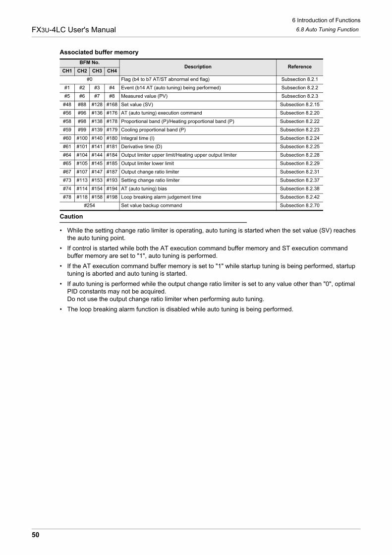
6 Introduction of Functions6.8 Auto Tuning FunctionFX3U-4LC User's Manual
Associated buffer memory
Caution
• While the setting change ratio limiter is operating, auto tuning is started when the set value (SV) reaches the auto tuning point.
• If control is started while both the AT execution command buffer memory and ST execution command buffer memory are set to "1", auto tuning is performed.
• If the AT execution command buffer memory is set to "1" while startup tuning is being performed, startup tuning is aborted and auto tuning is started.
• If auto tuning is performed while the output change ratio limiter is set to any value other than "0", optimal PID constants may not be acquired.Do not use the output change ratio limiter when performing auto tuning.
• The loop breaking alarm function is disabled while auto tuning is being performed.
BFM No.Description Reference
CH1 CH2 CH3 CH4#0 Flag (b4 to b7 AT/ST abnormal end flag) Subsection 8.2.1
#1 #2 #3 #4 Event (b14 AT (auto tuning) being performed) Subsection 8.2.2
#5 #6 #7 #8 Measured value (PV) Subsection 8.2.3
#48 #88 #128 #168 Set value (SV) Subsection 8.2.15
#56 #96 #136 #176 AT (auto tuning) execution command Subsection 8.2.20
#58 #98 #138 #178 Proportional band (P)/Heating proportional band (P) Subsection 8.2.22
#59 #99 #139 #179 Cooling proportional band (P) Subsection 8.2.23
#60 #100 #140 #180 Integral time (I) Subsection 8.2.24
#61 #101 #141 #181 Derivative time (D) Subsection 8.2.25
#64 #104 #144 #184 Output limiter upper limit/Heating upper output limiter Subsection 8.2.28
#65 #105 #145 #185 Output limiter lower limit Subsection 8.2.29
#67 #107 #147 #187 Output change ratio limiter Subsection 8.2.31
#73 #113 #153 #193 Setting change ratio limiter Subsection 8.2.37
#74 #114 #154 #194 AT (auto tuning) bias Subsection 8.2.38
#78 #118 #158 #198 Loop breaking alarm judgement time Subsection 8.2.42
#254 Set value backup command Subsection 8.2.70
50

6 Introduction of Functions6.8 Auto Tuning FunctionFX3U-4LC User's Manual
1
Introduction
2
Specification
3
System
Configuration
4
Installation
5
Wiring
6
Introduction of Functions
7
Alarm
8
Buffer Mem
ory
9
Program
Examples
10
Troubleshooting
6.8.2 Conditions for performing and aborting AT (auto tuning)
1. Conditions for performing AT (auto tuning)Auto tuning can be performed when all the following conditions are satisfied.• The control start/stop changeover set to "1 : Starts control".• The operation mode set to "3 : Monitor + alarm + Control".• The AUTO/MANUAL mode changeover set to "0 : AUTO mode".• The value stored in the output limiter upper limit/heating output limiter upper limit buffer memory is not the
same as the value stored in the output limiter lower limit buffer memory.• The value stored in the output limiter upper limit/heating output limiter upper limit buffer memory and the
value stored in the cooling output limiter upper limit buffer memory are "1 (0.1%)" or more.• The value stored in the output limiter lower limit buffer memory is "999 (99.9%)" or less.• Input value error (upper limit or lower limit) has not occurred.• The proportional band setting is not "0.0 (two-position control)".• The cascade ON/OFF set to "0 : Cascade OFF".• The AT/ST abnormal end flag is "0 (OFF)".
2. Conditions for aborting AT (auto tuning)If any of the following conditions are satisfied while auto tuning is being performed, auto tuning is forciblyaborted and the AT/ST abnormal end flag turns ON.• Input value error (upper limit or lower limit) occurs.• The set value (SV) is changed.• The control start/stop changeover function is changed to "0 : Stops control".• The AUTO/MANUAL mode changeover function is changed to "1 : MANUAL mode".• The operation mode is changed to any setting other than "3 : Monitor + Alarm + Control".• The AT bias is changed.• The sensor correction value is changed.• The primary delay digital filter setting is changed.• The value stored in the output limiter upper limit/heating output limiter upper limit buffer memory, the value
stored in the cooling output limiter upper limit buffer memory or the value stored in the output limiter lower limit buffer memory is changed.
• The proportional band setting is changed to "0.0 : two-position control".• A calculated PID constant acquired by auto tuning exceeds the setting range.
- Proportional band/heating proportional band and cooling proportional band : 0.1 to 1000.0- Integral time : 1 to 3600- Derivative time : 0 to 3600
• The AT execution command buffer memory is set to "0 : Stops AT".(AT/ST abnormal end flag does not turn ON.)
• Power failure occurs.(AT/ST abnormal end flag does not turn ON.)
• The cascade control ON/OFF function is set to "1 : Cascade ON".• The cooling method setting is changed.• Auto tuning is not finished in approximately 2 hours.• Hardware error is detected.
- Sum check error caused by 24V DC power supply error or adjustment data error- Cold contact temperature compensation data error- A/D converter error
51

6 Introduction of Functions6.8 Auto Tuning FunctionFX3U-4LC User's Manual
Associated buffer memoryBFM No.
Description ReferenceCH1 CH2 CH3 CH4
#0
Flag (b2 24V DC power supply error)(b4 to b7 AT/ST abnormal end flag)(b8 Adjustment data error)(b9 Cold contact temperature compensation data error)(b10 A/D converted value error)
Subsection 8.2.1
#1 #2 #3 #4
Event(b0 Input error (upper limit))(b1 Input error (lower limit))(b14 AT (auto tuning) being performed)
Subsection 8.2.2
#5 #6 #7 #8 Measured value (PV) Subsection 8.2.3
#29 Control start/stop changeover Subsection 8.2.9
#48 #88 #128 #168 Set value (SV) Subsection 8.2.15
#54 #94 #134 #174 AUTO/MANUAL mode changeover Subsection 8.2.18
#56 #96 #136 #176 AT (auto tuning) execution command Subsection 8.2.20
#57 #97 #137 #177 Operation mode Subsection 8.2.21
#58 #98 #138 #178 Proportional band (P)/Heating proportional band (P) Subsection 8.2.22
#59 #99 #139 #179 Cooling proportional band (P) Subsection 8.2.23
#60 #100 #140 #180 Integral time (I) Subsection 8.2.24
#61 #101 #141 #181 Derivative time (D) Subsection 8.2.25
#64 #104 #144 #184 Output limiter upper limit/Heating upper output limiter Subsection 8.2.28
#65 #105 #145 #185 Output limiter lower limit Subsection 8.2.29
#66 #106 #146 #186 Cooling upper output limiter setting Subsection 8.2.30
#67 #107 #147 #187 Output change ratio limiter Subsection 8.2.31
#68 #108 #148 #188 Sensor correction value setting Subsection 8.2.32
#72 #112 #152 #192 Primary delay digital filter setting Subsection 8.2.36
#74 #114 #154 #194 AT (auto tuning) bias Subsection 8.2.38
#78 #118 #158 #198 Loop breaking alarm judgement time Subsection 8.2.42
#208 #214 #220 #226 Input type Subsection 8.2.52
#244 #245 Cascade ON/OFF Subsection 8.2.64
#254 Set value backup command Subsection 8.2.70
52

6 Introduction of Functions6.8 Auto Tuning FunctionFX3U-4LC User's Manual
1
Introduction
2
Specification
3
System
Configuration
4
Installation
5
Wiring
6
Introduction of Functions
7
Alarm
8
Buffer Mem
ory
9
Program
Examples
10
Troubleshooting
6.8.3 AT (auto tuning) bias
Set the auto tuning bias so that the measured value (PV) does not exceed the set value (SV) during autotuning.The auto tuning function performs two-position control using the set value (SV), hunts the measured value(PV), then calculates and sets each PID constant. However, for some control targets, overshoot caused byhunting is not desirable. When the AT bias is set, the set value (SV) = AT point with which auto tuning isperformed can be changed.
Example of operation (When the AT bias is set to "-")
Associated buffer memory
Caution
• When the set value (SV) added by the AT bias (AT point) value exceeds the setting limiter range, the 4LC performs auto tuning using the setting limiter value.
• If the setting change ratio limiter is set to any value other than "0" when auto tuning is started, the set value (SV) changes in accordance with the setting of the setting change ratio limiter until the AT point. When the set value reaches the AT point, "Auto tuning being performed" of the event buffer memory turns ON, and auto tuning is started.
BFM No.Description Reference
CH1 CH2 CH3 CH4#1 #2 #3 #4 Event (b14 AT (auto tuning) being performed) Subsection 8.2.2
#73 #113 #153 #193 Setting change ratio limiter Subsection 8.2.37
#74 #114 #154 #194 AT (auto tuning) bias Subsection 8.2.38
#76 #116 #156 #196 Setting limiter upper limit Subsection 8.2.40
#77 #117 #157 #197 Setting limiter lower limit Subsection 8.2.41
AT starts
Time
Measured value (PV)
AT finishes
AT bias
AT point
Set value (SV)
53

6 Introduction of Functions6.9 Startup Tuning FunctionFX3U-4LC User's Manual
6.9 Startup Tuning Function
6.9.1 ST (startup tuning)
The startup tuning function automatically measures, calculates and sets optimal PID constants based on theresponse characteristics of the control target when control is started or when the set value (SV) is changed.Startup tuning works as easy as auto tuning, and acquires PID constants in a short time at start of controlwithout disturbing the controllability for a slow response control target. This function acquires PID constantsevery time the set value (SV) is changed for a control target requiring different PID constants at eachtemperature setting.Startup tuning is automatically started when control is started or when the set value (SV) is changed while allconditions for performing startup tuning are satisfied.The following buffer memories store calculated values.
When startup tuning is normally finished, the 4LC continues control using new calculated PID constants.
Example of operation
Explanation of operationIt is assumed that all conditions for performing startup tuning are satisfied.
→ For the conditions for performing startup tuning, refer to Subsection 6.9.2.1) Startup tuning is started when control is started. Optimal PID constants are obtained automatically based
on the response characteristics of the control target, and each constant is stored in the correspondingbuffer memory.
2) Startup tuning is started when the set value is changed. Optimal PID constants are obtainedautomatically based on the response characteristics of the control target, and each constant is stored inthe corresponding buffer memory.
Applicable buffer memory Calculated value Value to be set
Proportional band (P)Less than 0.1% 0.1%
1000.0% or more 1000.0%
Integral time (I)Less than 1 sec. 1 sec.
3600 sec. or more 3600 sec.
Derivative time (D) 3600 sec. or more 3600 sec.
ST starts
Time
Measured value (PV)
Set value (SV)1
Set value (SV)2
ST starts
(When control is started) (When the set value is changed)
PID constants are set PID constants are set
54
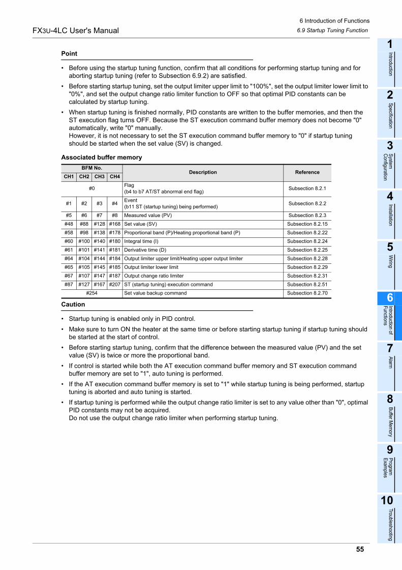
6 Introduction of Functions6.9 Startup Tuning FunctionFX3U-4LC User's Manual
1
Introduction
2
Specification
3
System
Configuration
4
Installation
5
Wiring
6
Introduction of Functions
7
Alarm
8
Buffer Mem
ory
9
Program
Examples
10
Troubleshooting
Point
• Before using the startup tuning function, confirm that all conditions for performing startup tuning and for aborting startup tuning (refer to Subsection 6.9.2) are satisfied.
• Before starting startup tuning, set the output limiter upper limit to "100%", set the output limiter lower limit to "0%", and set the output change ratio limiter function to OFF so that optimal PID constants can be calculated by startup tuning.
• When startup tuning is finished normally, PID constants are written to the buffer memories, and then the ST execution flag turns OFF. Because the ST execution command buffer memory does not become "0" automatically, write "0" manually.However, it is not necessary to set the ST execution command buffer memory to "0" if startup tuning should be started when the set value (SV) is changed.
Associated buffer memory
Caution
• Startup tuning is enabled only in PID control.• Make sure to turn ON the heater at the same time or before starting startup tuning if startup tuning should
be started at the start of control.• Before starting startup tuning, confirm that the difference between the measured value (PV) and the set
value (SV) is twice or more the proportional band.• If control is started while both the AT execution command buffer memory and ST execution command
buffer memory are set to "1", auto tuning is performed.• If the AT execution command buffer memory is set to "1" while startup tuning is being performed, startup
tuning is aborted and auto tuning is started.• If startup tuning is performed while the output change ratio limiter is set to any value other than "0", optimal
PID constants may not be acquired.Do not use the output change ratio limiter when performing startup tuning.
BFM No.Description Reference
CH1 CH2 CH3 CH4
#0 Flag (b4 to b7 AT/ST abnormal end flag) Subsection 8.2.1
#1 #2 #3 #4 Event(b11 ST (startup tuning) being performed) Subsection 8.2.2
#5 #6 #7 #8 Measured value (PV) Subsection 8.2.3
#48 #88 #128 #168 Set value (SV) Subsection 8.2.15
#58 #98 #138 #178 Proportional band (P)/Heating proportional band (P) Subsection 8.2.22
#60 #100 #140 #180 Integral time (I) Subsection 8.2.24
#61 #101 #141 #181 Derivative time (D) Subsection 8.2.25
#64 #104 #144 #184 Output limiter upper limit/Heating upper output limiter Subsection 8.2.28
#65 #105 #145 #185 Output limiter lower limit Subsection 8.2.29
#67 #107 #147 #187 Output change ratio limiter Subsection 8.2.31
#87 #127 #167 #207 ST (startup tuning) execution command Subsection 8.2.51
#254 Set value backup command Subsection 8.2.70
55

6 Introduction of Functions6.9 Startup Tuning FunctionFX3U-4LC User's Manual
6.9.2 Conditions for performing and aborting ST (startup tuning)
1. Conditions for performing ST (startup tuning)Startup tuning can be performed when all the following conditions are satisfied.• The ST execution command buffer memory is set to "1 : Performs ST".• The control start/stop changeover set to "1 : Starts control".• The operation mode set to "3 : Monitor + alarm + Control".• The AUTO/MANUAL mode changeover set to "0 : AUTO mode".• The value stored in the output limiter upper limit buffer memory is not the same as the value stored in the
output limiter lower limit buffer memory.• The value stored in the output limiter upper limit buffer memory is "1 (0.1%)" or more.• The value stored in the output limiter lower limit buffer memory is "999 (99.9%)" or less.• Input value error (upper limit or lower limit) has not occurred.• The proportional band setting is not "0.0 (two-position control)".• The cascade ON/OFF set to "0 : Cascade OFF".• PID control is selected. (ST cannot be performed during heating/cooling PID control)• The measured value (PV) is stable if startup tuning should be started when the set value (SV) is changed.• The output changes when startup tuning is started, and becomes saturated at the output limiter upper limit
or output limiter lower limit.• Before starting startup tuning, confirm that the difference between the measured value (PV) and the set
value (SV) is twice or more the proportional band.• The AT execution command buffer memory is set to "0 : Stops AT".• The AT/ST abnormal end flag is "0 (OFF)".
2. Conditions for aborting ST (startup tuning)If any of the following conditions are satisfied while startup tuning is being performed, startup tuning is forciblyaborted and the AT/ST abnormal end flag turns ON.• Input value error (upper limit or lower limit) occurs.• The control start/stop changeover function is changed to "0 : Stops control".• The AUTO/MANUAL mode changeover function is changed to "1 : MANUAL mode".• The operation mode is changed to any setting other than "3 : Monitor + Alarm + Control".• The sensor correction value is changed.• The primary delay digital filter setting is changed.• The value stored in the output limiter upper limit buffer memory or the value stored in the output limiter
lower limit buffer memory is changed.• The proportional band setting is changed to "0.0 : two-position control".• A calculated PID constant acquired by startup tuning exceeds the setting range.
- Proportional band : 0.1 to 1000.0- Integral time : 1 to 3600- Derivative time : 0 to 3600
• The ST execution command buffer memory is set to "0 : Stops ST".(AT/ST abnormal end flag does not turn ON.)
• Power failure occurs.(AT/ST abnormal end flag does not turn ON.)
• The cascade control ON/OFF function is set to "1 : Cascade ON".• Startup tuning is not finished in approximately 100 minutes.• The AT execution command buffer memory is set to "1 : Performs AT".
(The AT/ST abnormality flag does not turn ON.)
56

6 Introduction of Functions6.9 Startup Tuning FunctionFX3U-4LC User's Manual
1
Introduction
2
Specification
3
System
Configuration
4
Installation
5
Wiring
6
Introduction of Functions
7
Alarm
8
Buffer Mem
ory
9
Program
Examples
10
Troubleshooting
• The output saturation time (Time when the output value has stopped at output limiter upper limit or output limiter lower limit) is short.
• Hardware error is detected.- Sum check error caused by 24V DC power supply error or adjustment data error- Cold contact temperature compensation data error- A/D converter error
Associated buffer memoryBFM No.
Description ReferenceCH1 CH2 CH3 CH4
#0
Flag (b2 24V DC power supply error)(b4 to b7 AT/ST abnormal end flag)(b8 Adjustment data error)(b9 Cold contact temperature compensation data error)(b10 A/D converted value error)
Subsection 8.2.1
#1 #2 #3 #4
Event(b0 Input error (upper limit))(b1 Input error (lower limit))(b11 ST (startup tuning) being performed)(b14 AT (auto tuning) being performed)
Subsection 8.2.2
#5 #6 #7 #8 Measured value (PV) Subsection 8.2.3
#29 Control start/stop changeover Subsection 8.2.9
#48 #88 #128 #168 Set value (SV) Subsection 8.2.15
#54 #94 #134 #174 AUTO/MANUAL mode changeover Subsection 8.2.18
#56 #96 #136 #176 AT (auto tuning) execution command Subsection 8.2.20
#57 #97 #137 #177 Operation mode Subsection 8.2.21
#58 #98 #138 #178 Proportional band (P)/Heating proportional band (P) Subsection 8.2.22
#60 #100 #140 #180 Integral time (I) Subsection 8.2.24
#61 #101 #141 #181 Derivative time (D) Subsection 8.2.25
#64 #104 #144 #184 Output limiter upper limit/Heating upper output limiter Subsection 8.2.28
#65 #105 #145 #185 Output limiter lower limit Subsection 8.2.29
#67 #107 #147 #187 Output change ratio limiter Subsection 8.2.31
#68 #108 #148 #188 Sensor correction value setting Subsection 8.2.32
#72 #112 #152 #192 Primary delay digital filter setting Subsection 8.2.36
#87 #127 #167 #207 ST (startup tuning) execution command Subsection 8.2.51
#208 #214 #220 #226 Input type Subsection 8.2.52
#244 #245 Cascade ON/OFF Subsection 8.2.64
57

6 Introduction of Functions6.10 AUTO/MANUAL mode changeoverFX3U-4LC User's Manual
6.10 AUTO/MANUAL mode changeover
6.10.1 AUTO mode and MANUAL mode
The mode can be changed over between "AUTO mode" and "MANUAL mode".The AUTO mode is selected when "K0" is written to the AUTO/MANUAL mode changeover buffer memory.The MANUAL mode is selected when "K1" is written to the AUTO/MANUAL mode changeover buffermemory.Set the control mode to 0 to 3 (PID control) for performing manual mode.In the MANUAL mode, b13 of the event becomes ON to notify the MANUAL mode.0.25 sec is required to change over the mode.During changeover, the balance-less, bump-less function is actuated.
→ For details on the control mode switch, refer to Section 6.2.→ For details on the balance-less, bump-less function, refer to Subsection 6.10.2.
• AUTO modeIn the AUTO mode, the measured value (PV) or external input value is compared with the set value (SV), and the control output (MV) is given by PID arithmetic operation.The AUTO mode is selected at shipment.In the AUTO mode, the MANUAL output set value is always set to the control output value (MV).
• MANUAL modeBy changing the MANUAL output set value, the output value can be fixed to an arbitrary value.The actual output value is within the range from the output limiter lower limit to the output limiter upper limit.The output change ratio limiter setting is valid.The MANUAL output set value can be changed while b13 of the event is ON.
Associated buffer memory
Caution
• The MANUAL mode is not available while heating/cooling PID control is being performed.• Even in MANUAL mode, the temperature alarm function is functional.• The mode can be switched between AUTO/MANUAL mode even while external outputs are used.
BFM No.Description Reference
CH1 CH2 CH3 CH4#1 #2 #3 #4 Event (b13 MANUAL mode transition completed flag) Subsection 8.2.2
#25 #26 #27 #28 External input value Subsection 8.2.8
#54 #94 #134 #174 AUTO/MANUAL mode changeover Subsection 8.2.18
#55 #95 #135 #175 MANUAL output set value Subsection 8.2.19
#64 #104 #144 #184 Output limiter upper limit/Heating upper output limiter Subsection 8.2.28
#65 #105 #145 #185 Output limiter lower limit Subsection 8.2.29
#67 #107 #147 #187 Output change ratio limiter Subsection 8.2.31
58
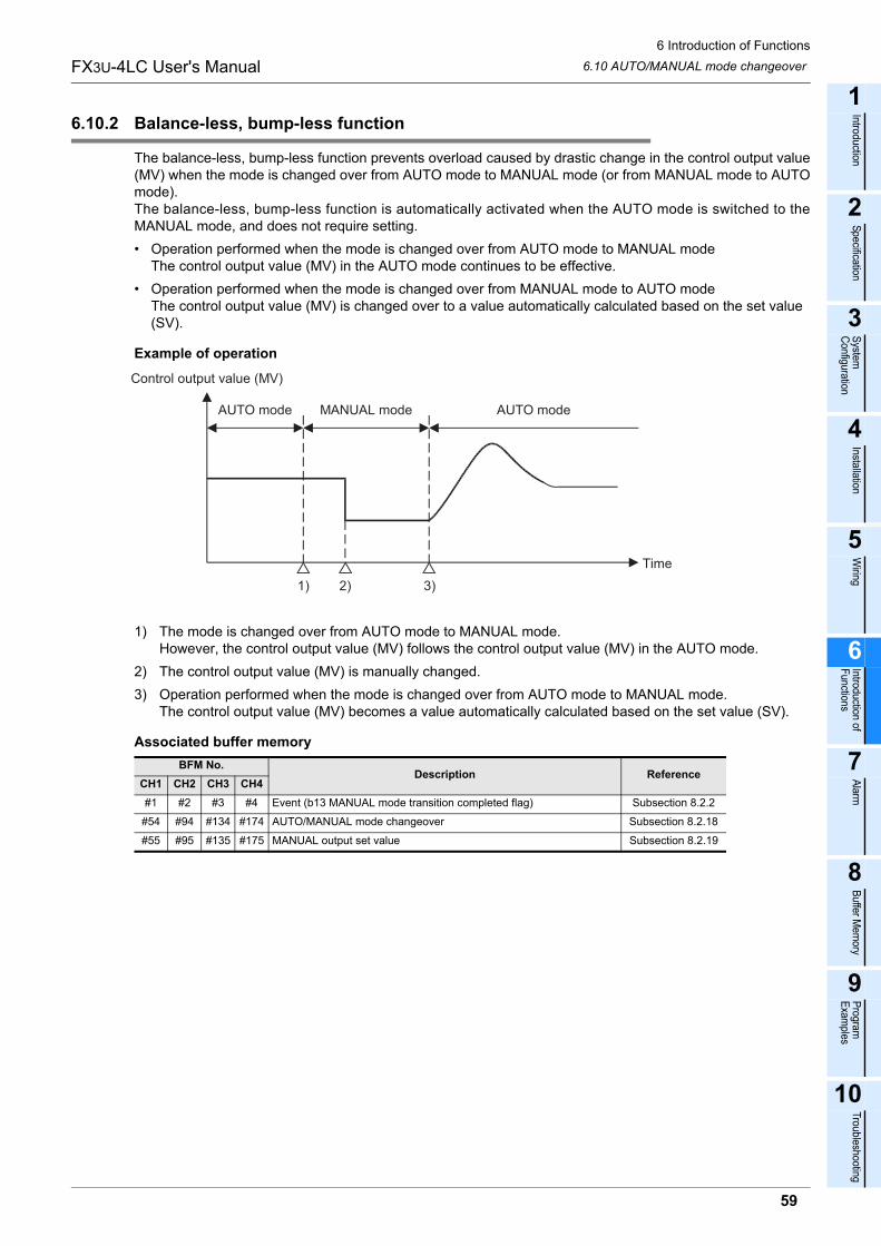
6 Introduction of Functions6.10 AUTO/MANUAL mode changeoverFX3U-4LC User's Manual
1
Introduction
2
Specification
3
System
Configuration
4
Installation
5
Wiring
6
Introduction of Functions
7
Alarm
8
Buffer Mem
ory
9
Program
Examples
10
Troubleshooting
6.10.2 Balance-less, bump-less function
The balance-less, bump-less function prevents overload caused by drastic change in the control output value(MV) when the mode is changed over from AUTO mode to MANUAL mode (or from MANUAL mode to AUTOmode).The balance-less, bump-less function is automatically activated when the AUTO mode is switched to theMANUAL mode, and does not require setting.• Operation performed when the mode is changed over from AUTO mode to MANUAL mode
The control output value (MV) in the AUTO mode continues to be effective.• Operation performed when the mode is changed over from MANUAL mode to AUTO mode
The control output value (MV) is changed over to a value automatically calculated based on the set value (SV).
Example of operation
1) The mode is changed over from AUTO mode to MANUAL mode.However, the control output value (MV) follows the control output value (MV) in the AUTO mode.
2) The control output value (MV) is manually changed.3) Operation performed when the mode is changed over from AUTO mode to MANUAL mode.
The control output value (MV) becomes a value automatically calculated based on the set value (SV).
Associated buffer memoryBFM No.
Description ReferenceCH1 CH2 CH3 CH4#1 #2 #3 #4 Event (b13 MANUAL mode transition completed flag) Subsection 8.2.2
#54 #94 #134 #174 AUTO/MANUAL mode changeover Subsection 8.2.18
#55 #95 #135 #175 MANUAL output set value Subsection 8.2.19
Control output value (MV)
AUTO mode MANUAL mode AUTO mode
Time
1) 3)2)
59

6 Introduction of Functions6.11 Heater Disconnection Alarm Function (HBA)FX3U-4LC User's Manual
6.11 Heater Disconnection Alarm Function (HBA)
6.11.1 Heater disconnection alarm function
The heater disconnection alarm function detects the current flowing in the load using a current detector (CT),it compares the detected value (heater current measured value) with the current value set for heaterdisconnection alarm, and issues an alarm when the measured value is more than or less than the current setvalue for the heater disconnection alarm. The heater current measured value can be measured using buffer memories.By setting the number of times of heater disconnection alarm delay, it is possible to issue an alarm whenabnormalities in the heater current measured value exceed the preset number of times.→ For details on the number of times of heater disconnection alarm delay, refer to Subsection 6.11.2.
Example of connection
OperationWhen either of the following occurs, it is considered as a cause for the heater disconnection alarm status andb9 of the event buffer memory turns ON.• When the heater current does not flow (Caused by heater disconnection, error in operating machine, etc.)
When the reference current measured value is equivalent to or less than the current set value for the heater disconnection alarm while the control output is ON, an alarm is issued.However, if the control output ON time is 0.22 sec or less, heater disconnection alarm function is not issued.
• When the heater current does not turn OFF (Caused by a molten relay, etc.)When the reference heater current measured value is more than the current set value for the heater disconnection alarm while the control output is OFF, an alarm is issued.However, if the control output OFF time is 0.22 sec or less, heater disconnection alarm function is not issued.
Current detector (CT)
Manufactured by U.R.D. Co., Ltd.Point
When using a current detector (CT) other than the above ones (CT) • Select a proper CT where the linearity of the output voltage in the desired range is satisfactory.• Select a proper CT whose coupling coefficient K is mainly near "1" in the measured current range.
Type Current measurement rangeCTL-12-S36-8 0.0 to 100.0A
CTL-12-S56-10 0.0 to 100.0A
CTL-6-P-H 0.0 to 30.0A
FX3U-4LC
Measuredvalue (PV)
Control output
Currentdetector input
Current detector (CT)
Sensor
Power supply
Solid state relay
Heater
Control target
60

6 Introduction of Functions6.11 Heater Disconnection Alarm Function (HBA)FX3U-4LC User's Manual
1
Introduction
2
Specification
3
System
Configuration
4
Installation
5
Wiring
6
Introduction of Functions
7
Alarm
8
Buffer Mem
ory
9
Program
Examples
10
Troubleshooting
Associated buffer memory
Caution
• Set a value lower than the actual heater current as the heater disconnection alarm set value.• When external output is selected in the control mode switch function, the heater disconnection alarm
function is disabled. Heater current measured value is always set to "0".• When the set value is "0", the heater disconnection alarm function is turned OFF. However, when turned
OFF, it is possible to monitor the heater current measured value.
6.11.2 Number of times of heater disconnection alarm delay
Set the number of times of delay for detecting heater disconnection alarm or current abnormality while theoutput is OFF.If abnormalities occur exceeding the preset number of times in the heater current measured value or currentvalue while the output is OFF, an alarm is issued.The sampling period is 500ms for the heater current measured value and the current value while the output isOFF.
Associated buffer memory
BFM No.Description Reference
CH1 CH2 CH3 CH4#1 #2 #3 #4 Event (b9 Heater disconnection alarm) Subsection 8.2.2
#21 #22 #23 #24 Heater current measured value Subsection 8.2.7
#53 #93 #133 #173 Heater disconnection alarm set value Subsection 8.2.17
#235 Number of times of heater disconnection alarm delay/Number of times of current error detection when output is OFF delay Subsection 8.2.57
#238 CT monitor method switch Subsection 8.2.60
#239 CT ratio setting Subsection 8.2.61
BFM No.Description Reference
CH1 CH2 CH3 CH4#1 #2 #3 #4 Event (b9 Heater disconnection alarm) Subsection 8.2.2
#21 #22 #23 #24 Heater current measured value Subsection 8.2.7
#53 #93 #133 #173 Heater disconnection alarm set value Subsection 8.2.17
#235 Number of times of heater disconnection alarm delay/Number of times of current error detection when output is OFF delay Subsection 8.2.57
61

6 Introduction of Functions6.12 Loop Breaking Alarm Function (LBA)FX3U-4LC User's Manual
6.12 Loop Breaking Alarm Function (LBA)
6.12.1 Loop breaking alarm function
The loop breaking alarm function starts to detect the variation of the measured value (PV), at every loopbreaking alarm judgment time when the output becomes more than 100% (or the output limiter upper limit) orless than 0% (or the output limiter lower limit), then sets to ON the loop breaking alarm (b8) when judging thatthere is an abnormality in the control loop.The loop breaking alarm function is enabled when the loop breaking alarm judgment time is set.It is possible to set a dead zone that is excluded from loop breaking detection.
→ For details on the loop breaking alarm judgement time, refer to Subsection 8.2.42.→ For details on the loop breaking alarm dead zone, refer to Subsection 6.12.2.
OperationLoop breaking alarm is issued in the following cases.• PID control (reverse operation)
• PID control (normal operation)
*1. The variation range for loop breaking alarm judgment is fixed as follows, and cannot be changed.2.0 C for internal temperature input0.2% of the scaling span for internal micro voltage input0.2% of the external input span for external input
• In heating/cooling PID controlThe loop breaking alarm function is disabled.
Abnormality targets• Abnormality in control target
Heater disconnection/short-circuit, lack of power supply, wiring mistake, etc.• Abnormality in sensor
Sensor disconnection, short-circuit, etc.• Abnormality in operating machine
Molten relay, wiring mistake, etc.• Abnormality in output circuit
Molten relay inside instrument, etc.• Abnormality in input circuit
No change in the measured value (PV) even after input has changed
Associated buffer memory
When output is less than 0% or output limiter lower limit
When measured value (PV) does not decrease at least by loop breaking changecriteria*1 within loop breaking alarm judgement time, an alarm is issued.
When output is more than 100% or output limiter upper limit
When measured value (PV) does not increase at least by loop breaking changecriteria*1 within loop breaking alarm judgement time, an alarm is issued.
When output is less than 0% or output limiter lower limit
When measured value (PV) does not decrease at leas by loop breaking changecriteria*1 within loop breaking alarm judgement time, an alarm is issued.
When output is more than 100% or output limiter upper limit
When measured value (PV) does not increase at least by loop breaking changecriteria*1 within loop breaking alarm judgement time, an alarm is issued.
BFM No.Description Reference
CH1 CH2 CH3 CH4#1 #2 #3 #4 Event (b8 Loop breaking alarm) Subsection 8.2.2
#5 #6 #7 #8 Measured value (PV) Subsection 8.2.3
#64 #104 #144 #184 Output limiter upper limit/Heating upper output limiter Subsection 8.2.28
#65 #105 #145 #185 Output limiter lower limit Subsection 8.2.29
#78 #118 #158 #198 Loop breaking alarm judgement time Subsection 8.2.42
#79 #119 #159 #199 Loop breaking alarm dead zone Subsection 8.2.43
62

6 Introduction of Functions6.12 Loop Breaking Alarm Function (LBA)FX3U-4LC User's Manual
1
Introduction
2
Specification
3
System
Configuration
4
Installation
5
Wiring
6
Introduction of Functions
7
Alarm
8
Buffer Mem
ory
9
Program
Examples
10
Troubleshooting
Caution
• The loop breaking alarm function judges abnormalities in the control loop, but cannot detect positions in which abnormalities occur. Check each part of the control system in turn.
• When the AT (auto tuning) function is completed, the loop breaking alarm judgement time is automatically set to the integral time result multiplied by 2.
• Set the time in which the measured increments changes by 2.0 C or 0.2% of the span or longer as the loop breaking alarm judgment time.If the loop breaking alarm judgement time is too short or is not suitable to control targets, the loop breaking alarm may repeatedly turn on and off or may not turn ON. In such a case, change the loop breaking alarm judgement time in accordance with the situation.
• In heating/cooling PID control, the loop breaking alarm function is disabled.• While AT (auto tuning) is performed, the loop breaking alarm function is disabled.• When the set value is "0", the loop breaking alarm function is disabled.• When the measured value (PV) is within the loop breaking alarm dead zone, alarm is not issued even if the
alarm issue condition is satisfied.• In heating/cooling PID control, the loop breaking alarm dead zone is invalid.
63

6 Introduction of Functions6.12 Loop Breaking Alarm Function (LBA)FX3U-4LC User's Manual
6.12.2 Loop breaking alarm dead zone (LBD)
Set the loop breaking alarm judgement time.The loop breaking alarm function may issue alarms caused by disturbances (effect of another heat source,etc.) even if there is no abnormality in the control system. In order to prevent such alarms, by setting the loopbreaking alarm dead zone, the region in which the alarm function is disabled (non-alarm status region) can beset.For example, if the loop breaking alarm dead zone is set to "10 C", 10 C above the set value (SV) and 10 Cbelow the set value (SV) are treated as the non-alarm status region (width of 20 C in total).
Example of operation
*1. While the temperature is rising : Alarm status regionWhile the temperature is decreasing : Non-alarm status region
*2. While the temperature is rising : Non-alarm status regionWhile the temperature is decreasing : Alarm status region
*3. Loop breaking alarm dead zone operation gap0.8 C for internal temperature input0.8% of the scaling span for internal micro voltage input0.8% of the external input span for external input
Associated buffer memory
Caution
• While the measured value (PV) is located within the non-alarm region, alarm is not issued even if the alarm condition is satisfied.
• In heating/cooling PID control, the loop breaking alarm dead zone is invalid.
BFM No.Description Reference
CH1 CH2 CH3 CH4#1 #2 #3 #4 Event (b8 Loop breaking alarm) Subsection 8.2.2
#5 #6 #7 #8 Measured value (PV) Subsection 8.2.3
#48 #88 #128 #168 Set value (SV) Subsection 8.2.15
#64 #104 #144 #184 Output limiter upper limit/Heating upper output limiter Subsection 8.2.28
#65 #105 #145 #185 Output limiter lower limit Subsection 8.2.29
#78 #118 #158 #198 Loop breaking alarm judgement time Subsection 8.2.42
#79 #119 #159 #199 Loop breaking alarm dead zone Subsection 8.2.43
Alarm status region Alarm status region
LBD operation gap*3 LBD operation gap*3Non-alarm status region
Temperature fall Temperature riseSet value (SV)
*1*2
LBD set value
Loop breakingalarm function
Loop breakingalarm function
OFF
ON
64

7 Alarm7.1 Alarm ListFX3U-4LC User's Manual
1
Introduction
2
Specification
3
System
Configuration
4
Installation
5
Wiring
6
Introduction of Functions
7
Alarm
8
Buffer Mem
ory
9
Program
Examples
10
Troubleshooting
7. Alarm
The 4LC is equipped with 14 types of alarms. Four types of alarms (alarm 1 to alarm 4) are available in eachchannel in accordance with the application.Set the alarm type by writing the alarm mode (0 to 14) to the alarm mode setting buffer memories for alarms 1to 4 (each channel).Values of alarms 1 to 4 can be set using the alarm set value buffer memories, and the alarm status can bechecked in the status of alarm bits (b4 to b7) for alarms 1 to 4 of the event buffer memory.The alarm dead zone and number of times of alarm delay can be set for the alarm function.By setting the alarm dead zone, it is possible to prevent repetition of alarm status and non-alarm status.By setting the number of times of alarm delay, alarm can be issued when the number of times of inputsampling exceeds the preset number of times of alarm delay.
→ For details on the event, refer to Subsection 8.2.2.→ For details on the alarm setting value, refer to Subsection 8.2.16.→ For details on the alarm mode setting, refer to Subsection 8.2.53.
→ For details on the alarm dead zone setting, refer to Section 7.3 or Subsection 8.2.55.→ For details on the number of times of alarm delay, refer to Section 7.4 or Subsection 8.2.56.
7.1 Alarm List
The list below shows alarms provided in the 4LC.→ For details on the alarm, refer to Section 7.2.
Alarm mode Alarm type Description Setting range Reference
0 Alarm function OFF Alarm function is disabled. - -
1 Upper limit input value alarm When measured value (PV) is more than alarm set value, analarm is issued. Input range*1 Subsection
7.2.1
2 Lower limit input value alarm When measured value (PV) is less than alarm set value, an alarmis issued. Input range*1 Subsection
7.2.2
3 Upper limit deviation alarm When deviation (= Measured value (PV) - Set value (SV)) is morethan alarm set value, an alarm is issued.
-Span to+Span*2*3
Subsection 7.2.3
4 Lower limit deviation alarm When deviation (= Measured value (PV) - Set value (SV)) is lessthan alarm set value, an alarm is issued.
-Span to+Span*2*3
Subsection 7.2.4
5 Upper/lower limit deviation When absolute deviation (= Measured value (PV) - Set value(SV)) is more than alarm set value, an alarm is issued. 0 to +Span*2*4 Subsection
7.2.5
6 Range alarm When absolute deviation (= Measured value (PV) - Set value(SV)) is less than alarm set value, an alarm is issued. 0 to +Span*2*4 Subsection
7.2.6
7 Upper limit input value alarmwith wait
When measured value (PV) is more than alarm set value, analarm is issued.However, when control is started the measured value is ignored.
Input range*1 Subsection 7.2.7
8 Lower limit input value alarmwith wait
When measured value (PV) is less than alarm set value, an alarmis issued.However, when control is started the measured value is ignored.
Input range*1 Subsection 7.2.7
9 Upper limit deviation valuealarm with wait
When deviation (= Measured value (PV) - Set value (SV)) is morethan alarm set value, an alarm is issued.However, when control is started the measured value is ignored.
-Span to+Span*2*3
Subsection 7.2.7
10 Lower limit deviation valuealarm with wait
When deviation (= Measured value (PV) - Set value (SV)) is lessthan alarm set value, an alarm is issued.However, when control is started the measured value is ignored.
-Span to+Span*2*3
Subsection 7.2.7
11 Upper/lower limit deviationvalue alarm with wait
When absolute deviation (= Measured value (PV) - Set value(SV)) is more than alarm set value, an alarm is issued.However, when control is started the measured value is ignored.
0 to +Span*2*4 Subsection 7.2.7
12 Upper limit deviation valuealarm with re-wait
When deviation (= Measured value (PV) - Set value (SV)) is morethan alarm set value, an alarm is issued.However, when control is started and when set value is changedthe measured value is ignored.
-Span to+Span*2*3
Subsection 7.2.8
65

7 Alarm7.1 Alarm ListFX3U-4LC User's Manual
*1. Input range for internal temperature inputScaling range for internal micro voltage inputExternal input range for external input
*2. Input span for internal temperature inputScaling span for internal micro voltage inputExternal input span for external input
*3. When the span exceeds 32767, the setting range is from -32768 to +32767.*4. When the span exceeds 32767, the setting range is from 0 to 32767.
13 Lower limit deviation valuealarm with re-wait
When deviation (= Measured value (PV) - Set value (SV)) is lessthan alarm set value, an alarm is issued.However, when control is started and when set value is changedthe measured value is ignored.
-Span to+Span*2*3
Subsection 7.2.8
14 Upper/lower limit deviationvalue alarm with re-wait
When absolute deviation (= Measured value (PV) - Set value(SV)) is more than alarm set value, an alarm is issued.However, when control is started and when set value is changedthe measured value is ignored.
0 to +Span*2*4 Subsection 7.2.8
Alarm mode Alarm type Description Setting range Reference
66

7 Alarm7.2 Alarm FunctionsFX3U-4LC User's Manual
1
Introduction
2
Specification
3
System
Configuration
4
Installation
5
Wiring
6
Introduction of Functions
7
Alarm
8
Buffer Mem
ory
9
Program
Examples
10
Troubleshooting
7.2 Alarm Functions
The alarm functions issue an alarm when the measured value (PV) or deviation [Measured value (PV) - Setvalue (SV)] reaches the alarm set value.The alarm status can be checked in the status of bits for alarms 1 to 4 of the event buffer memory.For settings of alarm functions, refer to the following.
→ For details on the event, refer to Subsection 8.2.2.→ For details on the measured value (PV), refer to Subsection 8.2.3.
→ For details on the set value (SV), refer to Subsection 8.2.15.→ For details on the alarm setting value, refer to Subsection 8.2.16.→ For details on the alarm mode setting, refer to Subsection 8.2.53.
Caution
• In cascade control, the alarm waiting operation is disabled on the slave channel side when the set value (SV) is changed.
• When the setting change ratio limiter is set to any value other than "0", the alarm waiting operation is disabled when the set value (SV) is changed.
7.2.1 Upper limit input value alarm
When the measured value (PV) is more than the alarm set value, an alarm is issued.
7.2.2 Lower limit input value alarm
When the measured value (PV) is less than the alarm set value, an alarm is issued.
Alarm set value
Measured value (PV)
Alarm statusNon-alarm status
Time
Measured value (PV)
Alarm status
Measured value (PV)
Time
Measured value (PV)
Non-alarm status
Alarm status
Alarm set value
Alarm status
67

7 Alarm7.2 Alarm FunctionsFX3U-4LC User's Manual
7.2.3 Upper limit deviation alarm
When the deviation (= Measured value (PV) - Set value (SV)) is more than the alarm set value, an alarm isissued.
7.2.4 Lower limit deviation alarm
When the deviation (= Measured value (PV) - Set value (SV)) is less than the alarm set value, an alarm isissued.
7.2.5 Upper/lower limit deviation
When the absolute deviation (= Measured value (PV) - Set value (SV)) is more than the alarm set value, analarm is issued.For example, if the alarm set value is "+10 C", an alarm is issued when the measured value (PV) is outsidethe range from "set value (SV) +10 C" to "set value (SV) -10 C".
Measured value (PV)
Deviation
Measured value (PV)
When the deviation is positive
Time
Measured value (PV)
Deviation
Measured value (PV)
When the deviation is negative
Time
Non-alarm status
Alarm status
Alarm set value
Alarm status
Set value (SV) Alarm set value
Set value (SV)
Alarm status
Measured value (PV)
Deviation
When the deviation is positive
Measured value (PV)
Alarm status
Deviation
Measured value (PV)
When the deviation is negative
Time
Alarm set value
Set value (SV) Alarm set value
Set value (SV)
Non-alarm status
Alarm status
Alarm status
Time
Measured value (PV)
Measured value (PV)
Alarm status
Non-alarm statusTime
Deviation
Deviation
Alarm set value
Set value (SV)
Alarm status
Alarm set value
Measured value (PV)
68

7 Alarm7.2 Alarm FunctionsFX3U-4LC User's Manual
1
Introduction
2
Specification
3
System
Configuration
4
Installation
5
Wiring
6
Introduction of Functions
7
Alarm
8
Buffer Mem
ory
9
Program
Examples
10
Troubleshooting
7.2.6 Range alarm
When the absolute deviation (= Measured value (PV) - Set value (SV)) is less than the alarm set value, analarm is issued.For example, if the alarm set value is "+10 C", an alarm is issued when the measured value (PV) is inside therange from "set value (SV) + 10 C" to "set value (SV) - 10 C".
7.2.7 Alarm wait operation
The wait operation ignores the alarm status of the measured value (PV) when control is started, and disablesthe alarm function until the measured value (PV) enters the alarm region after the wait period has ended.
Measured value (PV)
Alarm status
Non-alarm statusTime
Deviation
Deviation
Alarm set value
Set value (SV)
Alarm status
Alarm set value
Measured value (PV)
Measured value (PV)
Deviation
Measured value (PV)
When the wait operation is performed
Time
When the wait operation is not performed
Wait operation region
Measured value (PV)
Deviation
Measured value (PV)
Time
Set value (SV)
Alarm status
Alarm set value
Set value (SV)
Alarm set value
Alarm status
Alarm status
Non-alarm status
69

7 Alarm7.2 Alarm FunctionsFX3U-4LC User's Manual
7.2.8 Alarm re-wait operation
The alarm re-wait operation ignores the alarm status of the measured value (PV) when control is started, anddisables the alarm function until the measured value (PV) enters the alarm region after the wait period hasended.When the set value (SV) is changed, the measured value (PV) for deviation alarm changes accordingly.At this time, even if the measured value (PV) becomes the alarm status, the alarm re-wait function ignores itagain and disables the alarm function until the measured value (PV) goes out of the alarm status again.
Time
Measured value (PV)
Re-wait operation
Alarm status
Non-alarm status
Deviation
Deviation
Wait operation region
Set value is changed
Measured value (PV)
Wait operation region
Set value (SV)2
Alarm status
Alarm set value
Set value (SV)1
Alarm set value
70

7 Alarm7.3 Alarm Dead Zone SettingFX3U-4LC User's Manual
1
Introduction
2
Specification
3
System
Configuration
4
Installation
5
Wiring
6
Introduction of Functions
7
Alarm
8
Buffer Mem
ory
9
Program
Examples
10
Troubleshooting
7.3 Alarm Dead Zone Setting
In BFM#233, set the dead zone of alarms 1 to 4.This setting is applied to all of alarms 1 to 4.When the measured value (PV) is near the alarm set value, the alarm status and the non-alarm status may berepeated by fluctuation in inputs. In order to cope with such a case, by setting the alarm dead zone, repeatingof the alarm status and the non-alarm status can be prevented.
→ For details on the alarm dead band setting, refer to Subsection 8.2.55.
Upper limit input value alarm, Upper limit deviation alarm
Lower limit input value alarm, Lower limit deviation alarm
Upper/lower limit deviation
Measured value (PV)
Alarm status
Non-alarm statusTime
Measured value (PV)
Dead zone
Alarm status
Alarm set value
Measured value (PV)
Alarm status
Non-alarm statusTime
Measured value (PV)
Dead zone
Alarm status
Alarm set value
Time
Measured value (PV)
Dead zone
Measured value (PV)
Dead zone
Alarm status
Alarm set value
Alarm set value
Set value (SV)
Alarm status
Non-alarm status
71

7 Alarm7.4 Number of Times of Alarm DelayFX3U-4LC User's Manual
7.4 Number of Times of Alarm Delay
In BFM#234, set the number of alarm delays.This setting is applied to all alarms 1 to 4.The alarm delay function keeps the non-alarm status until the number of input samples exceeds the numberof alarm delays, after the deviation between the measured value (PV) and the set value (SV) reaches thealarm set value.If the deviation remains in the alarm range until the number of input samples exceeds the number of alarmdelays, an alarm is issued.
→ For details on the alarm delay count, refer to Subsection 8.2.56.
Time
Measured value (PV)Measured value (PV)
Input sampling
3 times 5 times
Alarm status
Alarm set value
Set value (SV)
Alarm status
Non-alarm status
72

8 Buffer Memory8.1 Buffer Memory ListFX3U-4LC User's Manual
1
Introduction
2
Specification
3
System
Configuration
4
Installation
5
Wiring
6
Introduction of Functions
7
Alarm
8
Buffer Mem
ory
9
Program
Examples
10
Troubleshooting
8. Buffer Memory
Each setting and alarm in the 4LC is written from or read to the PLC main unit through buffer memories.To read or write to the 4LC buffer memory, use FROM/TO instructions or specify buffer memory valuesdirectly.Each buffer memory consists of 16 bits. Use the FROM/TO instructions (or direct specification of buffermemory) in the 16-bit format.
→ For details of FROM/TO instructions (or direct specification of buffer memory),refer to the Programming Manual.
Caution
• If a value is written by mistake to a buffer memory used only for read, the written value is ignored. And 250ms later, the buffer memory is overwritten with a correct value.
• If a value outside the allowable set range is written to a buffer memory used both for read and write, the set value range error (b1) of the flag (BFM#0) turns ON. The buffer memory number in which an error has been generated is stored in a set value range error address (BFM#252). And the buffer memory in which the set value range error has occurred is controlled with the upper limit or the lower limit of the allowable set range.
8.1 Buffer Memory List
The table below provides a brief description and reference information for the 4LC buffer memory.→ For details on the buffer memory, refer to Section 8.2.
The "Remarks" column in the buffer memory list indicates the following.R/W : Read or WriteR : Read only
: Data can be backed-up using the set value backup command (BFM#254).: Handling numbers containing decimal places.
The set value should be the actual value multiplied by ten.The set value should be the actual value multiplied by "100" for the sensor correction value settingbuffer memories (BFM#68, BFM#108, BFM#148 and BFM#188), and multiplied by "1000" for thecascade gain buffer memories (BFM#246 and BFM#247).
: Handling integers or numbers containing decimal places according to the input range (setting of BFM#208, #214, #220 and #226). When handling numbers containing decimal places, multiply the set value by ten.BFM No.
Name Description/set range Initial value Remarks
CH1 CH2 CH3 CH4#0 Flag Refer to Subsection 8.2.1. - R - -
#1 #2 #3 #4 Event Refer to Subsection 8.2.2. - R - -
#5 #6 #7 #8 Measured value (PV) ±5% of input range - R -
#9 #10 #11 #12PID control Control output value (MV)
monitorOutput limiter upper limit tooutput limiter lower limit
- R -Heating/coolingPID control
Heating control output value (MV) monitor
-50 to heating output limiterupper limit (-5.0% to )
#13 #14 #15 #16PID control Not used -
- R -Heating/coolingPID control
Cooling control output value (MV) monitor
-50 to cooling output limiterupper limit (-5.0% to )
#17 #18 #19 #20 Control output flag Refer to Subsection 8.2.6. - R - -
#21 #22 #23 #24 Heater current measured value 0 to 1050 (0.0 to 105.0A) - R -
#25 #26 #27 #28 External input value -32768 to +32767 0 R/W - -
#29 Control start/stop changeover 0 : Stops control1 : Starts control 0 R/W - -
#30 FX Series model code K2090 2090 R - -
#31 Not used - - - - -
73

8 Buffer Memory8.1 Buffer Memory ListFX3U-4LC User's Manual
#32 #33 #34 #35PID control External output value monitor External output range lower
limit to External output rangeupper limit
0 R - -Heating/coolingPID control
Heating external output valuemonitor
#36 #37 #38 #39
PID control Not used - 0 - - -
Heating/coolingPID control
Cooling external output valuemonitor
External output range lowerlimit to External input rangeupper limit
0 R - -
#40 #41 #42 #43 Set value monitor Setting limiter lower limit to Setting limiter upper limit 0 R - -
#44 #45 #46 #47 Control mode monitor Refer to Subsection 8.2.14. 0 R - -
#48 #88 #128 #168 Set value (SV) Setting limiter lower limit to Setting limiter upper limit 0 R/W
#49 #89 #129 #169 Alarm 1 set value
Allowable set range variesdepending on alarm mode andinput type setting.
0 R/W#50 #90 #130 #170 Alarm 2 set value
#51 #91 #131 #171 Alarm 3 set value
#52 #92 #132 #172 Alarm 4 set value
#53 #93 #133 #173 Heater disconnection alarm set value 0 to 1000(0.0 to 100.0A) 0 R/W
#54 #94 #134 #174 AUTO/MANUAL mode changeover 0 : AUTO mode1 : MANUAL mode 0 R/W -
#55 #95 #135 #175PID control MANUAL output set value -50 to +1050
(-5.0 to +105.0%) -50 R/W -
Heating/cooling PID control Not used - 0 - - -
#56 #96 #136 #176 AT (auto tuning) execution command 0 : Stops Auto turning1 : Performs Auto turning 0 R/W -
#57 #97 #137 #177 Operation mode
0 : Not used1 : Monitor2 : Monitor + Alarm3 : Monitor + Alarm + Control
3 R/W -
#58 #98 #138 #178PID control Proportional band (P)
0 to 10000 (0.0 to 1000.0% ofspan)
30R/WHeating/cooling
PID control Heating proportional band (P) 30
#59 #99 #139 #179PID control Not used - 0 - - -
Heating/coolingPID control Cooling proportional band (P) 1 to 10000 (0.1 to 1000.0% of
span) 30 R/W
#60 #100 #140 #180 Integral time (I) 0 to 3600 sec. 240 R/W -
#61 #101 #141 #181 Derivative time (D) 0 to 3600 sec. 60 R/W -
#62 #102 #142 #182 Control response parameter0 : Slow1 : Medium2 : Fast
0 R/W -
#63 #103 #143 #183PID control Not used - 0 - - -
Heating/coolingPID control Overlap/Dead band -100 to +100
(-10.0 to +10.0% of span) 0 R/W -
#64 #104 #144 #184PID control Output limiter upper limit Output limiter lower limit + 1
to 1050 ( to 105.0%) 1000R/W
Heating/coolingPID control
Heating output limiter upperlimit 0 to 1050 (0.0 to 105.0%) 1000
#65 #105 #145 #185PID control Output limiter lower limit
-50 to Output limiter upper limit - 1(-5.0% to )
0 R/W
Heating/coolingPID control Not used - 0 - - -
#66 #106 #146 #186PID control Not used - 0 - - -
Heating/coolingPID control
Cooling upper output limitersetting 0 to 1050 (0.0 to 105.0%) 1000 R/W
#67 #107 #147 #187PID control Output change ratio limiter 0 to 1000 (0.0 to 100.0%/sec.) 0 R/W
Heating/coolingPID control Not used - 0 - - -
BFM No.Name Description/set range Initial
value RemarksCH1 CH2 CH3 CH4
74

8 Buffer Memory8.1 Buffer Memory ListFX3U-4LC User's Manual
1
Introduction
2
Specification
3
System
Configuration
4
Installation
5
Wiring
6
Introduction of Functions
7
Alarm
8
Buffer Mem
ory
9
Program
Examples
10
Troubleshooting
#68 #108 #148 #188 Sensor correction value setting -5000 to +5000(-50.00 to +50.00% of span) 0 R/W
#69 #109 #149 #189 Adjustment sensitivity (dead zone) setting 1 to 100 (0.1 to 10.0% of span) 10 R/W
#70 #110 #150 #190PID control Control output cycle setting
5 to 1000 (0.5 to 100.0 sec.)300
R/WHeating/coolingPID control
Heating control output periodsetting 300
#71 #111 #151 #191PID control Not used - 0 - - -
Heating/coolingPID control
Cooling control output periodsetting 5 to 1000 (0.5 to 100.0 sec.) 300 R/W
#72 #112 #152 #192 Primary delay digital filter setting 0 to 100 sec. 0 R/W -
#73 #113 #153 #193 Setting change ratio limiter 0 to 1000 (0.0 to 100.0% ofspan) 0 R/W
#74 #114 #154 #194 AT (Auto tuning) bias ±input span 0 R/W
#75 #115 #155 #195PID control Normal/reverse operation
selection0 : Normal operation1 : Reverse operation 1 R/W -
Heating/coolingPID control Not used - 0 - - -
#76 #116 #156 #196 Setting limiter upper limit Setting limiter lower limit + 1 toInput range upper limit 1300 R/W
#77 #117 #157 #197 Setting limiter lower limit Input range lower limit to Setting limiter upper limit - 1 -100 R/W
#78 #118 #158 #198PID control Loop breaking alarm judgement
time 0 to 7200 sec. 480 R/W -
Heating/cooling PID control Not used - 0 - - -
#79 #119 #159 #199PID control Loop breaking alarm dead zone 0 to input span 0 R/W
Heating/cooling PID control Not used - 0 - - -
#80 #120 #160 #200 Micro voltage input scaling upper limit -20000 to +20000(Reverse between upper limitand lower limit is not allowed.Span should be 20000 or less.)
10000 R/W -
#81 #121 #161 #201 Micro voltage input scaling lower limit 0 R/W -
#82 #122 #162 #202 External input range upper limit -32000 to +32000(Reverse between upper limitand lower limit is not allowed.)
10000 R/W -
#83 #123 #163 #203 External input range lower limit 0 R/W -
#84 #124 #164 #204 External output range upper limit -32000 to +32000(Reverse between upper limitand lower limit is not allowed.)
10000 R/W -
#85 #125 #165 #205 External output range lower limit 0 R/W -
#86 #126 #166 #206 Transistor output selection 0 to 7 0 R/W -
#87 #127 #167 #207 ST (startup tuning) execution command 0 : Stops Startup tuning1 : Performs Startup tuning 0 R/W - -
#208 #214 #220 #226 Input range 0 to 47 2 R/W -
#209 #215 #221 #227 Alarm 1 alarm mode setting
0 to 14
0
R/W
-
#210 #216 #222 #228 Alarm 2 alarm mode setting 0 -
#211 #217 #223 #229 Alarm 3 alarm mode setting 0 -
#212 #218 #224 #230 Alarm 4 alarm mode setting 0 -
#213 #219 #225 #231 Not used - 0 - - -
#232
PID control Not used - 0 - - -
Heating/coolingPID control cooling method setting
0 : Air cooling type1 : Water cooling type2 : Cooling gain linear type
0 R/W -
#233 Alarm dead band setting 0 to 100 (0.0 to 10.0% of span) 10 R/W
#234 Alarm delay count 0 to 30000 times 0 R/W -
#235Number of times of heater disconnection alarmdelay/Number of times of current error detectionwhen output is OFF delay
3 to 255 times 3 R/W -
#236 Temperature rise completion range setting 1 to 100 ( C/ F/ digit) 10 R/W -
BFM No.Name Description/set range Initial
value RemarksCH1 CH2 CH3 CH4
75

8 Buffer Memory8.1 Buffer Memory ListFX3U-4LC User's Manual
*1. Write "K2" to the initialization command (BFM #255) and initialize the buffer memory after changingthe input type or control mode.
#237 Temperature rise completion soak time 0 to 3600 sec. 0 R/W -
#238 CT monitor method switch0 : Monitors both ON current and OFF current1 : Monitors only ON current
0 R/W -
#239 CT ratio setting 1 to 9999 800 R/W -
#240 #241 Control mode switch0 to 3 : PID control4 to 7 : Heating/cooling PID control
0 R/W -
#242 #243PID control SV tracking selection 0 : Disable
1 : Enable 1 R/W -
Heating/coolingPID control Not used - 0 - - -
#244 #245PID control Cascade ON/OFF 0 : Cascade OFF
1 : Cascade ON 0 R/W - -
Heating/coolingPID control Not used - 0 - - -
#246 #247PID control Cascade gain -10000 to +10000
(-10.000 to +10.000 times) 1000 R/W
Heating/coolingPID control Not used - 0 - - -
#248 #249PID control Cascade bias -1000 to +1000
(-100.0 to +100.0%) 0 R/W
Heating/coolingPID control Not used - 0 - - -
#250 #251 Cascade monitor -32000 to +32000 0 R - -
#252 Set value range error address 0 : Normal1 to 255 : Setting error address 0 R - -
#253 Error reset command 0 : Performs nothing1 : Resets errors 0 R/W - -
#254 Set value backup command 0 : Normal1 : Starts to write EEPROM 0 R/W - -
#255 Initialization command
0 : Performs nothing1 : Initializes all data2 : Initializes BFM*1 #48 to #207, #232 and #242 to #247
0 R/W - -
#256 to #862 Not used - 0 - - -
BFM No.Name Description/set range Initial
value RemarksCH1 CH2 CH3 CH4
76

8 Buffer Memory8.2 Buffer Memory DetailsFX3U-4LC User's Manual
1
Introduction
2
Specification
3
System
Configuration
4
Installation
5
Wiring
6
Introduction of Functions
7
Alarm
8
Buffer Mem
ory
9
Program
Examples
10
Troubleshooting
8.2 Buffer Memory Details
8.2.1 [BFM#0] Flag
The ON/OFF status of each bit indicates the status of the 4LC.
Flag
Operation of temperature control ready flag (b15)Once the power supply has been turned ON the 4LC is ready. Temperature control ready flag turns ON.
Caution
• While the temperature control ready flag is ON, the 4LC accepts the FROM/TO instructions (or direct buffer memory specification).
• The 4LC does not perform control for approximately 5 seconds after the power is turned ON.
BFM No.Description Initial
value R/W BackupCH1 CH2 CH3 CH4
#0 Flag (Refer to the following) - R -
Bit Item Descriptionb0 Error present Turns ON when an error among b1 to b10 below has occurred.
b1 Set value range errorTurns ON when data outside set range is written.The buffer memory number in which an error has been generated isstored in a set value range error address (BFM#252).
b2 24V DC power supply error Turns ON when driving power supply (24V DC) is not supplied. Thecontrol output of all channels is turned OFF.
b3 Set value backup error flag
Turns ON when an error has been caused by noise, when a failurehas occurred in the 4LC, or when the backup command is set toOFF during backup.Turn the power ON again, and check for changes in the state. If noimprovement is obtained, consult your local Mitsubishi Electricrepresentative.
b4 CH1 AT/ST abnormal end flag Turns ON when CH1 AT (auto tuning) or ST (startup tuning)abnormally ends.
b5 CH2 AT/ST abnormal end flag Turns ON when CH2 AT (auto tuning) or ST (startup tuning)abnormally ends.
b6 CH3 AT/ST abnormal end flag Turns ON when CH3 AT (auto tuning) or ST (startup tuning)abnormally ends.
b7 CH4 AT/ST abnormal end flag Turns ON when CH4 AT (auto tuning) or ST (startup tuning)abnormally ends.
b8 Adjustment data error
Turns ON when an error has been caused by noise or when afailure has occurred in the 4LC. The control output of all channels isturned OFF.Turn the power ON again, and check for changes in the state. If noimprovement is obtained, consult your local Mitsubishi Electricrepresentative.
b9 Cold contact temperature compensation data errorTurns ON when an error has been caused by noise or when afailure has occurred in the 4LC. The control output of error channelsis turned OFF.The error channels can be checked in the status of bits of Eventbuffer memories (BFM#1 to #4).Turn the power ON again, and check for changes in the state. If noimprovement is obtained, consult your local Mitsubishi Electricrepresentative.
b10 A/D converted value error
b11 Not used -b12 Controlling flag Turns ON when 4LC is performing control.b13 Set value being backed up flag Remains ON while set values are being backed up.b14 Initialization completed flag Turns ON when Initialization completedb15 Temperature control ready flag Turns ON when 4LC becomes ready for operation.
Temperature controlready flag(b15)
Power is turned ON Temperature control CPUready for operation
500ms maximumON
OFF
77

8 Buffer Memory8.2 Buffer Memory DetailsFX3U-4LC User's Manual
8.2.2 [BFM#1 to 4] Event
The ON/OFF status of each bit indicates the status of each channel.The bit assignment is the same for all channels.
Event
Explanation of operation of the temperature rise completed flag (b15)This bit notifies that the measured value (PV) reaches near the set value (SV).When the measured value reaches the temperature rise completion range (BFM#236) and the soak time(BFM#237) is finished, temperature rise completed flag (b15) turns ON.
→ For details on the temperature rise completion range, refer to Subsection 8.2.58.→ For details on the temperature rise completion soak time, refer to Subsection 8.2.59.
BFM No.Description Initial
value R/W BackupCH1 CH2 CH3 CH4#1 #2 #3 #4 Event (Refer to the following) - R -
Bit Item Descriptionb0 Input error (upper limit) Turns ON when input value is over scale.
b1 Input error (lower limit) Turns ON when input value is under scale.
b2 Cold contact temperature compensation data error Turns ON when an error has been caused by noise or when afailure has occurred in the 4LC.Turn the power ON again, and check for changes in the state. If noimprovement is obtained, consult your local Mitsubishi Electricrepresentative.
b3 A/D converted value error
b4 Alarm 1 Turns ON when an alarm 1 has occurred.
b5 Alarm 2 Turns ON when an alarm 2 has occurred.
b6 Alarm 3 Turns ON when an alarm 3 has occurred.
b7 Alarm 4 Turns ON when an alarm 4 has occurred.
b8 Loop breaking alarm Turns ON when a loop breaking alarm has occurred
b9 Heater disconnection alarm Turns ON when a heater disconnection alarm has occurred.
b10 Current error when output is OFF Turns ON when a current error occurs while output is OFF.
b11 ST (startup tuning) being performed Remains ON while startup tuning is being performed.
b12 Decimal point positionTurns ON when input range is set to "0.1 C/ F".0 : 1 C/ F, mV1 : 0.1 C/ F
b13 MANUAL mode transition completed flagTurns ON when transition to manual mode is completed.0 : AUTO mode1 : MANUAL mode
b14 AT (auto tuning) being performed Remains ON while auto tuning is being performed.
b15 Temperature rise completed flag Turns ON when the temperature rise completion soak time isfinished within the temperature rise completion range.
Temperature risecompletion range (BFM#236)
Temperature risecompleted flag
(b15)
Set value (SV)
Temperature risecompletion soaktime (BFM#237)
Measured value(PV)
ON
OFF
78

8 Buffer Memory8.2 Buffer Memory DetailsFX3U-4LC User's Manual
1
Introduction
2
Specification
3
System
Configuration
4
Installation
5
Wiring
6
Introduction of Functions
7
Alarm
8
Buffer Mem
ory
9
Program
Examples
10
Troubleshooting
8.2.3 [BFM#5 to 8] Measured value (PV)
These buffer memories store the measured value (PV).The unit is " C", "0.1 C", " F", "0.1 F" or "mV" in accordance with the input type setting. The displayed measured value (PV) is as follows depending on the input type used.• When internal input is used
1) These buffer memories store the input value detected by the 4LC subject to the following processing.- Sensor correction- Primary delay digital filter setting
2) These buffer memories store the following value in accordance with the decimal point position.- When the decimal point position is "0", these buffer memories store the measured value as it is.- When the decimal point position is "1", these buffer memories store the measured value multiplied by
"10".• When external input is used
1) These buffer memories store the value written in the external input value buffer memory subject to thefollowing processing.
- Sensor correction- Primary delay digital filter setting
→ For details on the input type, refer to Subsection 8.2.52.→ For details on the decimal point position, refer to Subsection 8.2.2.
→ For details on the sensor correction, refer to Subsection 8.2.32.→ For details on the primary delay digital filter setting, refer to Subsection 8.2.36.
Caution
• When handing a numeric value containing decimal places, these buffer memories store the actual value multiplied by "10".
• "0" is displayed due to measurement data sampling for approximately 5 seconds after the power is turned ON.The 4LC does not perform control during this period.
BFM No.Description Initial
value R/W BackupCH1 CH2 CH3 CH4
#5 #6 #7 #8
Display range : • When internal temperature input is given:
"Input range lower limit - 5% of span" to "Input range upper limit +5% of span"
• When internal micro voltage input is given:"Scaling lower limit - 5% of span" to "Scaling upper limit + 5% ofspan"
• When external temperature input is given."External input range lower limit - 5% of span" to "External inputrange upper limit + 5% of span"
- R -
79

8 Buffer Memory8.2 Buffer Memory DetailsFX3U-4LC User's Manual
8.2.4 [BFM#9 to 12] Control output value (MV) monitor/Heating control output value (MV) monitor
In standard PID control, these buffer memories store the control output value (MV) after PID arithmeticoperation or control output value (MV) in MANUAL mode.In heating/cooling PID control, these buffer memories store the heating control output (MV) after heating/cooling PID arithmetic operation.
Caution
• These buffer memories handle numeric values containing decimal places, and store the actual value multiplied by "10".
• These buffer memories store the -5.0% past the lower limit of the span when control is stopped.
8.2.5 [BFM#13 to 16] Cooling control output value (MV) monitor
In heating/cooling PID control, these buffer memories store the cooling control output value (MV) afterheating/cooling PID arithmetic operation.
Caution
• These buffer memories handle numeric values containing decimal places, and store the actual value multiplied by "10".
• In PID control, these buffer memories store "0". (Not used)• These buffer memories store the -5.0% past the lower limit of the span when control is stopped.
BFM No.Description Initial
value R/W BackupCH1 CH2 CH3 CH4
#9 #10 #11 #12
Display range : • PID control :
Output limiter lower limit to Output limiter upper limit• Heating/cooling PID control :
-50 to Heating upper output limiter (-5.0% past lower limit )
- R -
BFM No.Description Initial
value R/W BackupCH1 CH2 CH3 CH4
#13 #14 #15 #16 Display range : -50 to Cooling upper output limiter (-5.0% past lower limit ) - R -
80

8 Buffer Memory8.2 Buffer Memory DetailsFX3U-4LC User's Manual
1
Introduction
2
Specification
3
System
Configuration
4
Installation
5
Wiring
6
Introduction of Functions
7
Alarm
8
Buffer Mem
ory
9
Program
Examples
10
Troubleshooting
8.2.6 [BFM#17 to 20] Control output flag
Bit 0 and bit 8 indicate the ON/OFF status of the control output.However, the contents of control output vary depending on the setting of the control mode switch function andtransistor output selection function.When internal transistor outputs are assigned to the control output, bit 0 and bit 8 indicate the transistoroutput status (ON or OFF). When internal transistor outputs are not assigned to the control output, bit 0 andbit 8 indicate the output status (ON or OFF) in the arithmetic operation result in proportion to time (controloutput cycle).
Control output flag
→ For details on the control mode switch, refer to Subsection 8.2.62.→ For details on the transistor output selection function, refer to Section 6.3.
Caution
Bits other than bits 0 and 8 are always "0 (OFF)".
BFM No.Description Initial
value R/W BackupCH1 CH2 CH3 CH4#17 #18 #19 #20 Control output flag (Refer to the following) - R -
Control type Control mode switch
Transistor output selection function Channel
Contents of control outputBit8 Bit0
PID control
0 to 1 - - Not used Transistor output status
2 to 3
0 - Not used Arithmetic operation result in proportion to time
1 to 2 - Not used Transistor output status
3 to 7 - Not used Arithmetic operation result in proportion to time
Heating/cooling PID control
4 to 5 -
1,3 Cooling-side transistor status
Heating-side transistor output status
2,4Cooling-side output
Arithmetic operation result in proportion to time
Heating-side output Arithmetic operation result
in proportion to time
6 to 7
0 -Cooling-side output
Arithmetic operation result in proportion to time
Heating-side output Arithmetic operation result
in proportion to time
1 -Cooling-side output
Arithmetic operation result in proportion to time
Heating-side transistor output status
2 - Cooling-side transistor output status
Heating-side output Arithmetic operation result
in proportion to time
3 to 7 -Cooling-side output
Arithmetic operation result in proportion to time
Heating-side output Arithmetic operation result
in proportion to time
BFM#17,BFM#18,BFM#19,BFM#20
Bit
08 7 6 5 4 3 2 19101112131415
Bit
81

8 Buffer Memory8.2 Buffer Memory DetailsFX3U-4LC User's Manual
8.2.7 [BFM#21 to 24] Heater current measured value
These buffer memories store the heater current measured value entered from the current detector (CT).
Caution
• These buffer memories handle numeric values containing decimal places, and store the actual value multiplied by "10".
• When the control mode using external outputs is selected by the control mode switch function, the CT input is not measured. In this case, these buffer memories always store "0".
• When heating/cooling PID control using external outputs is used control, the CT input is not measured. In this case, these buffer memories always store "0".
→ For details on the control mode switch, refer to Subsection 8.2.62.
8.2.8 [BFM#25 to 28] External input value
When the control mode using external outputs is selected by the control mode switch function, set a valuecorresponding to the measured value (PV) to these buffer memories.
→ For details on the control mode switch, refer to Subsection 8.2.62.
Caution
• When the setting in the external input value is greater than the external input range upper limit +5%, it is judged as an input upper limit error, and bit 0 of the event buffer memory (BFM#1 to BFM#4) turns ON.
• When the setting in the external input value is smaller than the external input range lower limit - 5%, it is judged as an input lower limit error, and bit 1 of the event buffer memory (BFM#1 to BFM#4) turns ON.
8.2.9 [BFM#29] Control start/stop changeover
This buffer memory starts or stops control.Write "K0" to stop control and select the monitor mode.Write "K1" to start the operation selected by the operation mode setting buffer memory.The setting of this buffer memory is effective for all channels.
→ For details on the operation mode, refer to Subsection 8.2.21.
Caution
• When the PLC main unit is changed over from "RUN" to "STOP", outputs of the 4LC are held. In order to stop outputs of the 4LC, make sure to use BFM#29.
• When the operation mode setting buffer memory is set to "0 (Not used)", the measured value (PV) becomes "0".
8.2.10 [BFM#30] FX Series model code
The model code of the 4LC is stored.
BFM No.Description Initial
value R/W BackupCH1 CH2 CH3 CH4#21 #22 #23 #24 Display range : 0 to 1050 (0.0 to 105.0A) - R -
BFM No.Description Initial
value R/W BackupCH1 CH2 CH3 CH4#25 #26 #27 #28 Setting range : -32768 to +32767 0 R/W -
BFM No.Description Initial
value R/W BackupCH1 CH2 CH3 CH4
#29 0 : Stops control1 : Starts control 0 R/W -
BFM No.Description Initial
value R/W BackupCH1 CH2 CH3 CH4
#30 The model code of the 4LC is K2090. K2090 R -
82

8 Buffer Memory8.2 Buffer Memory DetailsFX3U-4LC User's Manual
1
Introduction
2
Specification
3
System
Configuration
4
Installation
5
Wiring
6
Introduction of Functions
7
Alarm
8
Buffer Mem
ory
9
Program
Examples
10
Troubleshooting
8.2.11 [BFM#32 to 35] External output value/Heating external output value monitor
When the control mode using external outputs is selected by the control mode switch function, these buffermemories store the control output processed within the output limit and scaled into the external output range.
→ For details on the control mode switch, refer to Subsection 8.2.62.
Caution
When internal output is selected by a control mode change, a control output value (MV) is stored.→ For details on the control output value (MV), refer to Subsection 8.2.4.
8.2.12 [BFM#36 to 39] Cooling external output value monitor
When the control mode using external outputs is selected by the control mode switch function, these buffermemories store the cooling control output processed within the output limit and scaled into the external outputrange.
→ For details on the control mode switch, refer to Subsection 8.2.62.
Caution
When internal output is selected by a control mode change, a cooling control output value (MV) is stored.→ For details on the cooling control output value (MV), refer to Subsection 8.2.5.
8.2.13 [BFM#40 to 43] Set value monitor
These buffer memories store the set value used in PID control and alarm function.These buffer memories indicate transient changes in the set value on the slave side when the setting changeratio limiter is set or during cascade control.
→ For details on the setting change ratio limiter, refer to Subsection 8.2.37.→ For details on the cascade control, refer to Section 6.7.
BFM No.Description Initial
value R/W BackupCH1 CH2 CH3 CH4
#32 #33 #34 #35 Display range : External output range lower limit to external output range upper limit 0 R -
BFM No.Description Initial
value R/W BackupCH1 CH2 CH3 CH4
#36 #37 #38 #39 Display range : External output range lower limit to external output range upper limit 0 R -
BFM No.Description Initial
value R/W BackupCH1 CH2 CH3 CH4#40 #41 #42 #43 Display range : Setting limiter lower limit to Setting limiter upper limit 0 R -
83

8 Buffer Memory8.2 Buffer Memory DetailsFX3U-4LC User's Manual
8.2.14 [BFM#44 to 47] Control mode monitor
These buffer memories indicate the current control mode and cascade control status.Bit 0 to bit 2 indicate the control mode, and bit 15 indicates the cascade control status.
→ For details on the control mode, refer to Subsection 8.2.62.→ For details on the cascade control, refer to Section 6.7.
Control mode (b2 to b0)
Cascade control status (b15)
Caution
Bit 3 to bit 14 are always "0 (OFF)".
BFM No.Description Initial
value R/W BackupCH1 CH2 CH3 CH4#44 #45 #46 #47 Refer to the following 0 R -
Bit2 to Bit0 of value Control mode Control type Input Output
0 0
PID control
InternalInternal
1 1 External
2 2 InternalExternal
3 3 External
4 4
Heating/cooling PID control
InternalInternal
5 5 External
6 6 InternalExternal
7 7 External
Bit15 Description0 (OFF) Cascade control is not being performed.
1 (ON) Cascade control is being performed.
BFM#44,BFM#45,BFM#46,BFM#47
Bit
08 7 6 5 4 3 2 19101112131415
Bit
Control modeExample :When bits 0 and 1 are OFF and bit 2 is ON, the value from bit 0 to bit 2 becomes "4".
BFM#44,BFM#45,BFM#46,BFM#47
Bit
08 7 6 5 4 3 2 19101112131415
Bit
Cascade control status
84

8 Buffer Memory8.2 Buffer Memory DetailsFX3U-4LC User's Manual
1
Introduction
2
Specification
3
System
Configuration
4
Installation
5
Wiring
6
Introduction of Functions
7
Alarm
8
Buffer Mem
ory
9
Program
Examples
10
Troubleshooting
8.2.15 [BFM#48][BFM#88][BFM#128][BFM#168] Set value (SV)
To these buffer memories, enter the set value (SV) used in the PID arithmetic operation and alarm function.The unit is " C", "0.1 C", " F", "0.1 F" or "mV" in accordance with the input type setting (BFM#208, BFM#214,BFM#220 and BFM#226). Enter a value as follows in accordance with the decimal point position.When the decimal point position is "0", enter a value as it is. When the decimal point position is "1", enter avalue multiplied by "10".
→ For details on the decimal point position, refer to Subsection 8.2.2.→ For details on the setting limiter upper limit, refer to Subsection 8.2.40.→ For details on the setting limiter lower limit, refer to Subsection 8.2.41.
→ For details on the input type, refer to Subsection 8.2.52.
8.2.16 [BFM#49 to 52][BFM#89 to 92][BFM#129 to 132][BFM#169 to 172]Alarm setting value 1 to 4
To these buffer memories, enter the set value of each alarm set by the alarm mode setting buffer memories.The alarm mode setting buffer memories allow arbitrary selection of 4 types of alarms among available 14types of alarms. Write the setting value 1 to 4 of the alarm after setting the alarm mode. The unit and settingrange of the set value vary depending on the selected alarm mode. Enter the set value suitable to theselected alarm mode.
→ For details on the alarm mode setting, refer to Subsection 8.2.53.
Setting range
*1. Input range for internal temperature input. Scaling range for internal micro voltage input. External inputrange for external input.
*2. Input span for internal temperature input. Scaling span for internal micro voltage input. External inputspan for external input.
*3. When the span exceeds 32767, the setting range is from -32768 to +32767.*4. When the span exceeds 32767, the setting range is from 0 to 32767.
Caution
When handling numbers containing decimal places, multiply the set value by 10.
BFM No.Description Initial
value R/W BackupCH1 CH2 CH3 CH4
#48 #88 #128 #168 Setting range : Setting limiter lower limit to Setting limiter upper limit 0 R/W
BFM No.Description Initial
value R/W BackupCH1 CH2 CH3 CH4Alarm 1 setting value
#49 #89 #129 #169 Setting range : Refer to the following 0 R/W
Alarm 2 setting value
#50 #90 #130 #170 Setting range : Refer to the following 0 R/W
Alarm 3 setting value
#51 #91 #131 #171 Setting range : Refer to the following 0 R/W
Alarm 4 setting value
#52 #92 #132 #172 Setting range : Refer to the following 0 R/W
Alarm mode Setting range0 Alarm function OFF - - - - 0
1 Upper limit input value alarm 7 Upper limit input value alarm
with wait - - Input range*1
2 Lower limit input value alarm 8 Lower limit input value alarm
with wait - - Input range*1
3 Upper limit deviation alarm 9 Upper limit deviation value
alarm with wait 12 Upper limit deviation value alarm with re-wait -span to +span*2*3
4 Lower limit deviation alarm 10 Lower limit deviation value
alarm with wait 13 Lower limit deviation value alarm with re-wait -span to +span*2*3
5 Upper/lower limit deviation 11 Upper/lower limit deviation
value alarm with wait 14 Upper/lower limit deviation value alarm with re-wait 0 to +span*2*4
6 Range alarm - - - - 0 to +span*2*4
85

8 Buffer Memory8.2 Buffer Memory DetailsFX3U-4LC User's Manual
8.2.17 [BFM#53][BFM#93][BFM#133][BFM#173] Heater disconnection alarm set value
To these buffer memories, enter a value for recognizing heater disconnection or recognizing abnormal currentwhile the output is OFF.• While the control output is ON
When the heater current measured value is equivalent to or smaller than the heater disconnection alarm set value, a heater disconnection alarm is issued. (b9 of the Event BFM for the relevant channel turns ON.)
• While the control output is OFFWhen the heater current measured value is equivalent to or larger than the heater disconnection alarm set value, an abnormal current alarm in the output OFF status is issued. (b10 of the Event BFM for the relevant channel turns ON.)
→ For details on the heater disconnection alarm, refer to Section 6.11.→ For details on the heater current measured value, refer to Subsection 8.2.7.
Caution
• Handling numbers containing decimal places. The set value should be the actual value multiplied by 10.• As the heater disconnection alarm set value, enter a value smaller than the actual heater current.• When the control mode using external outputs is selected by the control mode switch function, the heater
disconnection alarm function is disabled.• When "0" is entered, the heater disconnection alarm function is disabled.
8.2.18 [BFM#54][BFM#94][BFM#134][BFM#174] AUTO/MANUAL mode changeover
These buffer memories select AUTO mode or MANUAL mode.Write "K0" to select AUTO mode.Write "K1" to select MANUAL mode.• AUTO mode
The measured value (PV) or external input value is compared with the set value (SV), PID arithmetic operation is performed, and then the control output (MV) is given.In AUTO mode, the MANUAL output set value becomes equivalent to the control output value (MV).
• MANUAL modeThe control output (MV) is given based on the MANUAL output set value.
→ For details on the AUTO/MANUAL mode changeover, refer to Section 6.10.
Caution
• MANUAL mode is not available while heating/cooling PID control is being performed.• The alarm function is also enabled in MANUAL mode.• The mode can be switched between AUTO/MANUAL mode even while external outputs are used.
BFM No.Description Initial
value R/W BackupCH1 CH2 CH3 CH4
#53 #93 #133 #173 Setting range : 0 to 1000 (0.0 to 100.0A) 0 R/W
BFM No.Description Initial
value R/W BackupCH1 CH2 CH3 CH4
#54 #94 #134 #174 0 : AUTO mode1 : MANUAL mode 0 R/W
86

8 Buffer Memory8.2 Buffer Memory DetailsFX3U-4LC User's Manual
1
Introduction
2
Specification
3
System
Configuration
4
Installation
5
Wiring
6
Introduction of Functions
7
Alarm
8
Buffer Mem
ory
9
Program
Examples
10
Troubleshooting
8.2.19 [BFM#55][BFM#95][BFM#135][BFM#175] MANUAL output set value
To these buffer memories, set the output ON ratio in MANUAL mode.Specify the ratio of the ON duration within the time (sec) specified by the control output cycle setting buffermemories.ON duration : Control output cycle (sec) × MANUAL output set value (%)
→ For details on the control output cycle setting, refer to Subsection 8.2.34.
*1. 0 in the case of heating/cooling PID control.*2. These buffer memories can be written only in MANUAL mode.
Example of operation(When the control output cycle is 30 sec and the MANUAL output set value is 60%)
Caution
• Handling numbers containing decimal places. The set value should be the actual value multiplied by 10.• These buffer memories can be written only in MANUAL mode.• Write these buffer memories after transfer to MANUAL mode is completed (that is, after b13 of the event
buffer memory turns ON).• The actual output value is within the range from the output limiter lower limit to the output limiter upper limit.• In AUTO mode, these buffer memories automatically store the control output value (MV).
→ For details on the event, refer to Subsection 8.2.2.
8.2.20 [BFM#56][BFM#96][BFM#136][BFM#176] AT (auto tuning) execution command
These buffer memories stop or perform auto tuning.Write "K0" to stop auto tuning.Write "K1" to perform auto tuning.
→ For details on the AT (auto tuning), refer to Section 6.8.
Caution
• When performing auto tuning again, write "K0", wait for 0.5 sec or more, and then write "K1" again.• Auto tuning can be performed in PID control and heating/cooling PID control.• Auto tuning is not started if conditions for performing auto tuning are not satisfied.
→ For details on the conditions for performing AT (auto tuning), refer to Subsection 6.8.2.
BFM No.Description Initial
value R/W BackupCH1 CH2 CH3 CH4
#55 #95 #135 #175
Setting range :• PID control :
50 to +1050 (-5.0% to +105.0%)• Heating/cooling PID control :
0 (Not used)
-50*1 R/W*2 -
BFM No.Description Initial
value R/W BackupCH1 CH2 CH3 CH4
#56 #96 #136 #176 0 : Stops AT (auto turning)1 : Performs AT (auto turning) 0 R/W
Control outputON
OFF
Control output cycle30 sec.
18 sec. 12 sec.
60% 40%
87

8 Buffer Memory8.2 Buffer Memory DetailsFX3U-4LC User's Manual
8.2.21 [BFM#57][BFM#97][BFM#137][BFM#177] Operation mode
These buffer memories specify the operation mode among "Monitor + Alarm + Control", "Monitor + Alarm","Monitor" and "Not used".Write "K0" not to use the channel.Write "K1" to only monitor the measured value.Write "K2" to monitor the measured value and issue alarms.Write "K3" to monitor the measured value, issue alarms and perform control (all operations).The operation status varies depending on the combination with the setting of the control start/stopchangeover buffer memory. For the details, refer to "Operation status resulting from the combination with thesetting of the control start/stop changeover buffer memory" below.
→ For details on the control start/stop changeover, refer to Subsection 8.2.9.
Operation status resulting from the combination with the setting of the control start/stop changeover buffer memory
*1. For details on the transistor output selection function, refer to Section 6.3.
BFM No.Description Initial
value R/W BackupCH1 CH2 CH3 CH4
#57 #97 #137 #177
0 : Not used1 : Monitor2 : Monitor + Alarm3 : Monitor + Alarm + Control
3 R/W
Starts control/Stops
control
Description
Operation mode
0 : Not used 1 : Monitor 2 : Monitor + Alarm
3 : Monitor + Alarm + Control
0 : Stops control
Measured value (PV) 0 Measured value is displayed.
Alarm operation Alarm function is disabled.
Output(Transistor output selection 0 to 2)*1
Output OFF
Output (Transistor output selection 3 to 6)*1
Output OFF
Output(Transistor output selection 7)*1
Output OFF
1 : Starts control
Measured value (PV) 0 Measured value is displayed.
Alarm operation Alarm function is disabled. Alarm function is enabled.
Output(Transistor output selection 0 to 2)*1
Output OFF
Arithmeticoperation result in proportion to
time
Output (Transistor output selection 3 to 6)*1
Output OFF Alarm status
Output(Transistor output selection 7)*1
Output OFF Loop breaking alarm status
88

8 Buffer Memory8.2 Buffer Memory DetailsFX3U-4LC User's Manual
1
Introduction
2
Specification
3
System
Configuration
4
Installation
5
Wiring
6
Introduction of Functions
7
Alarm
8
Buffer Mem
ory
9
Program
Examples
10
Troubleshooting
8.2.22 [BFM#58][BFM#98][BFM#138][BFM#178] Proportional band (P)/Heating proportional band (P)
To these buffer memories, set the proportional band (P) for performing standard PID control, or theproportional band (P) on the heating side for performing heating/cooling PID control.The proportional band is required to give the control output in proportion to the deviation (difference betweenthe set value (SV) and the measured value (PV)).As the value set here increases, changes in the control output (MV) versus changes in the input becomesmaller. Conversely, as the value set here decreases, changes in the control output (MV) become larger.Note that too large a proportional band value increases the overshoot, and requires a longer time until theoutput value (MV) reaches the set value (SV) and becomes stable.
*1. Input span for internal temperature inputScaling span for internal micro voltage inputExternal input span for external input
Caution
• Handling numbers containing decimal places. The set value should be the actual value multiplied by 10.• In standard PID control, the set value "0" specifies two-position operation.• In heating/cooling PID control, the set value "0" specifies two-position operation on both the heating side
and the cooling side.
8.2.23 [BFM#59][BFM#99][BFM#139][BFM#179] Cooling proportional band (P)
To these buffer memories, set the proportional band (P) on the cooling side for performing heating/coolingPID control.
*1. Input span for internal temperature inputScaling span for internal micro voltage inputExternal input span for external input
*2. 30 in the case of heating/cooling PID control.Caution
• Handling numbers containing decimal places. The set value should be the actual value multiplied by 10.• When "0" is set to the proportional band on the heating side, the setting of the proportional band on the
cooling side is invalid. It is not possible to perform two-position operation only on the cooling side.
BFM No.Description Initial
value R/W BackupCH1 CH2 CH3 CH4
#58 #98 #138 #178 Setting range : 0 to 10000 (0.0 to 1000.0% of span)*1 30 R/W
BFM No.Description Initial
value R/W BackupCH1 CH2 CH3 CH4
#59 #99 #139 #179
Setting range :• PID control :
0 (Not used)• Heating/cooling PID control :
1 to 10000 (0.1 to 1000.0% of span)*1
0*2 R/W
89

8 Buffer Memory8.2 Buffer Memory DetailsFX3U-4LC User's Manual
8.2.24 [BFM#60][BFM#100][BFM#140][BFM#180] Integral time (I)
To these buffer memories, set the integral time (I) for performing PID control.The integral operation changes the control output in proportion to the area made by the deviation size anddeviation generation time.In proportional operation, deviation (difference between the set value (SV) and the measured value (PV)) maybe generated due to natural radiation even if the control output is stable.Integral operation eliminates this deviation. The integral time refers to the time in which the control outputgiven by the proportional operation is obtained only by the integral operation.As the integral time is decreased, the integral efficiency is better.
Caution
When "0" is entered, the integral time (I) setting is invalid.
8.2.25 [BFM#61][BFM#101][BFM#141][BFM#181] Derivative time (D)
To these buffer memories, set the derivative time (D) for performing PID control.Derivative operation changes the control output in proportion to the change in speed of the measured value(PV) to prevent an increase in the deviation (difference between the set value (SV) and the measured value(PV)).Because derivative operation responds to the rate at which the measured value (PV) changes, the responseto disturbances (noise in measured value caused by external factors) is improved. The derivative time refersto the time in which the control output given by proportional operation is obtained only by derivative operationwhile the deviation increases and decreases at a constant ratio.As the derivative time increases, the derivative effect increases.
Caution
When "0" is entered, the derivative time (D) setting is invalid.
BFM No.Description Initial
value R/W BackupCH1 CH2 CH3 CH4
#60 #100 #140 #180 Setting range : 0 to 3600 (sec.) 240 R/W
BFM No.Description Initial
value R/W BackupCH1 CH2 CH3 CH4
#61 #101 #141 #181 Setting range : 0 to 3600 (sec.) 60 R/W
90

8 Buffer Memory8.2 Buffer Memory DetailsFX3U-4LC User's Manual
1
Introduction
2
Specification
3
System
Configuration
4
Installation
5
Wiring
6
Introduction of Functions
7
Alarm
8
Buffer Mem
ory
9
Program
Examples
10
Troubleshooting
8.2.26 [BFM#62][BFM#102][BFM#142][BFM#182] Control response parameter
To these buffer memories, set the control response parameter.Select the response to changes in the set value (SV) in PID control among three steps (slow, medium andfast).Write "K0" to specify "Slow".Write "K1" to specify "Medium".Write "K2" to specify "Fast".
Explanation of operation
BFM No.Description Initial
value R/W BackupCH1 CH2 CH3 CH4
#62 #102 #142 #1820 : Slow1 : Medium2 : Fast
0 R/W
Set value DescriptionK0 : Slow Set this value to restrain the overshoot.
K1 : Medium The overshoot is smaller than "2: Fast".
K2 : Fast Set this value to reduce the rising time (that is, to start operation early).Note that some overshoot cannot be avoided.
Time
Measured value(PV)
Set value(SV)1
Set value(SV)2
(K2 : Fast)
(K1 : Medium)
(K0 : Slow)
Set value (SV) change point
Changed
91

8 Buffer Memory8.2 Buffer Memory DetailsFX3U-4LC User's Manual
8.2.27 [BFM#63][BFM#103][BFM#143][BFM#183] Overlap/Dead band
To these buffer memories, set the range of the overlap area or dead band for heating/cooling PID control.Enter a value in the range from -100 to -1 (negative value) to set the overlap area.Enter a value in the range from +1 to +100 (positive value) to set the dead band.Set "0" not to use the overlap area or dead band.
→ For details on the overlap/dead band, refer to Subsection 6.6.3.
*1. Input span for internal temperature inputScaling span for internal micro voltage inputExternal input span for external input
*2. These buffer memories can be written only while heating/cooling PID control is being performed.
Explanation of operationOverlap:The proportional band on the heating side and proportional band on the cooling side overlap in the overlaparea.When the measured value (PV) is located within the overlap area, both the control output on the heating sideand the control output on the cooling side are given at the same time.Dead band:The dead band (dead zone) is located between the proportional band on the heating side and the proportionalband on the cooling side.When the measured value (PV) is located within the dead band, both the control output on the heating sideand the control output on the cooling side are not output.
Caution
• The setting of the overlap area/dead band is invalid while two-position control is being performed.• Set the overlap area within the proportional band setting range.
BFM No.Description Initial
value R/W BackupCH1 CH2 CH3 CH4
#63 #103 #143 #183
Setting range : • PID control :
0 (Not used)• Heating/cooling PID control :
-100 to +100 (-10.0 to +10.0% of span)*1
0 R/W*2
100%
0%
Heatingoutput value
Heatingproportional
band
Coolingproportional
band
Measuredvalue (PV)
Set value(SV)
OverlapDeadband
Coolingoutput value
Control output value (MV)
92

8 Buffer Memory8.2 Buffer Memory DetailsFX3U-4LC User's Manual
1
Introduction
2
Specification
3
System
Configuration
4
Installation
5
Wiring
6
Introduction of Functions
7
Alarm
8
Buffer Mem
ory
9
Program
Examples
10
Troubleshooting
8.2.28 [BFM#64][BFM#104][BFM#144][BFM#184] Output limiter upper limit/Heating upper output limiter
To these buffer memories, set the output limiter upper limit/heating output limiter upper limit for setting theupper limit of the control output value (MV).Set the upper limit of the output for standard PID control.Set the upper limit of the output on the heating side for heating/cooling PID control.
→ For details on the output limiter lower limit, refer to Subsection 8.2.29.→ For details on the cooling upper output limiter setting, refer to Subsection 8.2.30.
Example of operation
Caution
• Handling numbers containing decimal places. The set value should be the actual value multiplied by 10.• The setting of the output limiter upper limit/heating output limiter upper limit is invalid while two-position
control is being performed.• The setting of the output limiter lower limit is invalid while heating/cooling PID control is being performed.• Proper PID constants may not be obtained if the output limiter upper limit/heating output limiter upper limit
is set and auto tuning is performed.Do not set the output limiter upper limit/heating output limiter upper limit when performing auto tuning.
BFM No.Description Initial
value R/W BackupCH1 CH2 CH3 CH4
#64 #104 #144 #184
Setting range : • PID control :
Output limiter lower limit + 1 to 1050 ( to 105.0%)• Heating/cooling PID control :
0 to 1050 (0.0 to 105.0%)
1000 R/W
Output limiter upper limit
Output limiter lower limit
100%
0%
Control output value (MV)
This range is excluded from thecontrol output.
This range is excluded from thecontrol output.
93

8 Buffer Memory8.2 Buffer Memory DetailsFX3U-4LC User's Manual
8.2.29 [BFM#65][BFM#105][BFM#145][BFM#185] Output limiter lower limit
To these buffer memories, set the output limiter lower limit for setting the lower limit of the control output value(MV).
→ For an operation example of the output limiter lower limit, refer to Subsection 8.2.28.→ For details on the output limiter upper limit/heating upper output limiter, refer to Subsection 8.2.28.
*1. These buffer memories can be written only while standard PID control is being performed.Caution
• Handling numbers containing decimal places. The set value should be the actual value multiplied by 10.• The setting of the output limiter lower limit is invalid while two-position control is being performed.• The setting of the output limiter lower limit is invalid while heating/cooling PID control is being performed.• Proper PID constants may not be obtained if the output limiter lower limit is set and auto tuning is
performed.Do not set the output limiter lower limit when performing auto tuning.
8.2.30 [BFM#66][BFM#106][BFM#146][BFM#186] Cooling upper output limiter setting
To these buffer memories, set the output limiter upper limit on the cooling side for setting the upper limit of thecontrol output value (MV) on the cooling side.→ For details on the output limiter upper limit/heating upper output limiter, refer to Subsection 8.2.28.
*1. 1000 in the case of heating/cooling PID control.*2. These buffer memories can be written only while heating/cooling PID control is being performed.
Caution
• Handling numbers containing decimal places. The set value should be the actual value multiplied by 10.• The setting of the cooling output limiter upper limit is invalid while two-position control is being performed.• The setting of the cooling output limiter upper limit is invalid while standard PID control is being performed.• Proper PID constants may not be obtained if the cooling output limiter upper limit is set and auto tuning is
performed.Do not set the cooling output limiter upper limit when performing auto tuning.
BFM No.Description Initial
value R/W BackupCH1 CH2 CH3 CH4
#65 #105 #145 #185
Setting range : • PID control :
-50 to Output limiter upper limit-1 (-5.0% to )• Heating/cooling PID control :
0 (Not used)
0 R/W*1
BFM No.Description Initial
value R/W BackupCH1 CH2 CH3 CH4
#66 #106 #146 #186
Setting range : • PID control :
0 (Not used)• Heating/cooling PID control :
0 to 1050 (0.0 to 105.0%)
0*1 R/W*2
94

8 Buffer Memory8.2 Buffer Memory DetailsFX3U-4LC User's Manual
1
Introduction
2
Specification
3
System
Configuration
4
Installation
5
Wiring
6
Introduction of Functions
7
Alarm
8
Buffer Mem
ory
9
Program
Examples
10
Troubleshooting
8.2.31 [BFM#67][BFM#107][BFM#147][BFM#187] Output change ratio limiter
The output change ratio limiter function limits changes in the control output value (MV) per unit time (1 sec).The preset output change ratio limits the control output.The output does not change drastically but is given in accordance with the preset inclination when the poweris turned ON (and the output is outside the proportional band) or when the set value is changed (significantly).
*1. These buffer memories can be written only while standard PID control is being performed.
Example of operation
Caution
• Handling numbers containing decimal places. The set value should be the actual value multiplied by 10.• Entering a small value to these buffer memories (to make the inclination smaller) makes the control
response slow, and eliminates the derivative effect.• The output change ratio limiter is disabled while two-position control is being performed.• The output change ratio limiter is disabled while heating/cooling PID control is being performed.• The output change ratio limiter is disabled when "0" is entered to these buffer memories.• Proper PID constants may not be obtained if the output change ratio limiter is set and auto tuning is
performed.Do not set the output change ratio limiter when performing auto tuning.
BFM No.Description Initial
value R/W BackupCH1 CH2 CH3 CH4
#67 #107 #147 #187
Setting range : • PID control :
0 to 1000 (0.0 to 100.0%/sec.)• Heating/cooling PID control :
0 (Not used)
0 R/W*1
When the output change ratio limiter is not used
0.1 to100.0%
1 sec.
Output limiter upper limit
Output limiter lower limit
Drastic changes in outputcaused by power ON, change ofthe set value, disturbance, etc.
Set how many percentages theoperation output is to bechanged in 1 sec.
Control output value (MV)
Outputdrasticallychanges
Control output value (MV)
95

8 Buffer Memory8.2 Buffer Memory DetailsFX3U-4LC User's Manual
8.2.32 [BFM#68][BFM#108][BFM#148][BFM#188] Sensor correction value setting
To these buffer memories, enter the sensor correction value for correcting the dispersion among sensors orcorrecting differences in the measured value (PV) from other instruments.The actual input value is added to the sensor correction value, and then stored in the measured value (PV)buffer memory.
→ For details on the measured value (PV), refer to Subsection 8.2.3.
*1. Input span for internal temperature inputScaling span for internal micro voltage inputExternal input span for external input
Example of operation
ConditionWhen the input range span is 400 C and correction by 2 C is required
Sensor correction value2 ( C)/400 ( C) × 100 = 0.5 (%)
Display valueDisplayed value = Measured value (PV) + Sensor correction value
Caution
Handling numbers containing decimal places. The set value should be the actual value multiplied by 100.
BFM No.Description Initial
value R/W BackupCH1 CH2 CH3 CH4
#68 #108 #148 #188 Setting range : -5000 to +5000 (-50.00 to +50.00% of span)*1 0 R/W
Time
Measured value (PV) Correction value
Display value
Actual measured value
Set value (SV)
: 2 C
96

8 Buffer Memory8.2 Buffer Memory DetailsFX3U-4LC User's Manual
1
Introduction
2
Specification
3
System
Configuration
4
Installation
5
Wiring
6
Introduction of Functions
7
Alarm
8
Buffer Mem
ory
9
Program
Examples
10
Troubleshooting
8.2.33 [BFM#69][BFM#109][BFM#149][BFM#189] Adjustment sensitivity (dead zone) setting
To these buffer memories, enter the adjustment sensitivity (dead zone) to prevent chattering of the controloutput (MV) around the set value (SV) during two-position control.The value entered to these buffer memories is divided into two and distributed upward and downward aroundthe set value (SV).
→ For details on the set value (SV), refer to Subsection 8.2.15.
*1. Input span for internal temperature inputScaling span for internal micro voltage inputExternal input span for external input
Example of operationWhen the input range span is 400 C and the adjustment sensitivity (dead zone) is set to "10%"400 ( C) × 10.0 (%) / 100 = 40 ( C)When the set value is 200 C, the range from 180 to 220 C is handled as the dead zone.
Caution
• Handling numbers containing decimal places. The set value should be the actual value multiplied by 10.• Entering a large value (to create wide adjustment sensitivity area (dead zone)) increases vertical
fluctuation. Entering too small a value generates chattering due to small oscillations of the measured value.
BFM No.Description Initial
value R/W BackupCH1 CH2 CH3 CH4
#69 #109 #149 #189 Setting range : 1 to 100 (0.1 to 10.0% of span)*1 10 R/W
Set value (SV)
Control output (MV)
Time
"40 " is divided into two anddistributed upward and downwardaround the set value (SV).
220
180
20
20
OFF
ON
The adjustment sensitivity (dead zone) isset to "40 ".
200C
C
CC
C
C
C
97

8 Buffer Memory8.2 Buffer Memory DetailsFX3U-4LC User's Manual
8.2.34 [BFM#70][BFM#110][BFM#150][BFM#190] Control output cycle setting/Heating control output period setting
To these buffer memories, enter the control output (MV) cycle. For heating/cooling PID control, enter thecontrol output (MV) cycle on the heating side.Set the time in which the control output (MV) turns ON and OFF.The ON duration and OFF duration of the control output (MV) are as follows.ON duration : Control output cycle/Control output cycle on heating side (sec) × Control output value (%)OFF duration : Control output cycle/Control output cycle on heating side (sec) × (100 - Control output value (%))
Example of operation (When the control output cycle is 30 sec and the control output value (MV) is 60%)
Caution
Handling numbers containing decimal places. The set value should be the actual value multiplied by 10.
8.2.35 [BFM#71][BFM#111][BFM#151][BFM#191] Cooling control output period setting
To these buffer memories, enter the control output (MV) cycle on the cooling side for heating/cooling PIDcontrol.The ON duration and OFF duration of the control output (MV) are as follows.ON duration : Control output cycle on cooling side (sec) × Control output value (%)OFF duration : Control output cycle on cooling side (sec) × (100 - Control output value (%))
→ For an operation example of the control output cycle on the cooling side,refer to Subsection 8.2.34.
*1. 300 in the case of heating/cooling PID control.*2. These buffer memories can be written only while heating/cooling PID control is being performed.
Caution
Handling numbers containing decimal places. The set value should be the actual value multiplied by 10.
BFM No.Description Initial
value R/W BackupCH1 CH2 CH3 CH4
#70 #110 #150 #190 Setting range : 5 to 1000 (0.5 to 100.0 sec.) 300 R/W
BFM No.Description Initial
value R/W BackupCH1 CH2 CH3 CH4
#71 #111 #151 #191
Setting range : • PID control :
0 (Not used)• Heating/cooling PID control :
5 to 1000 (0.5 to 100.0 sec.)
0*1 R/W*2
Control output (MV)ON
OFF
Control output cycle30 sec.
18 sec. 12 sec.
98

8 Buffer Memory8.2 Buffer Memory DetailsFX3U-4LC User's Manual
1
Introduction
2
Specification
3
System
Configuration
4
Installation
5
Wiring
6
Introduction of Functions
7
Alarm
8
Buffer Mem
ory
9
Program
Examples
10
Troubleshooting
8.2.36 [BFM#72][BFM#112][BFM#152][BFM#192] Primary delay digital filter setting
To these buffer memories, enter the primary delay digital filter for reducing fluctuations caused by noise in themeasured value (MV).The effect of noise is mitigated by setting the time constant of the digital filter here in accordance with thecontrol target characteristics and noise level.Entering too small a value may not give the filter a beneficial effect. Entering too large a value deteriorates theinput response.
Example of operation
Caution
• The primary delay digital filter is invalid when "0" is entered, and the measured value is acquired in the sampling period (250ms).
• When the measured value (PV) before processing by the digital filter is outside the acquisition range (input value error) continuously in 2 sampling periods, the digital filter is not applied.
BFM No.Description Initial
value R/W BackupCH1 CH2 CH3 CH4
#72 #112 #152 #192 Setting range : 0 to 100 (sec.) 0 R/W
Input of actual measured value (PV)
Input of measured value (PV) processedby the primary delay digital filter
Amplitude processed by the filter
Input amplitude
Pulse input caused by noise
Time
Time
Time
Time
99

8 Buffer Memory8.2 Buffer Memory DetailsFX3U-4LC User's Manual
8.2.37 [BFM#73][BFM#113][BFM#153][BFM#193] Setting change ratio limiter
When the set value (SV) is changed, the setting change ratio limiter function changes the difference betweenthe former set value (SV) and the new set value (SV) gradually. Use this function to avoid drastic change inthe set value (SV).To these buffer memories, enter the change ratio (%) of the set value per minute.The set value monitor buffer memory indicates the set value (SV) is being changed.
→ For details on the set value monitor, refer to Subsection 8.2.13.
*1. Input span for internal temperature inputScaling span for internal micro voltage inputExternal input span for external input
Example of operation (When the set value (SV) 1 is changed to a larger set value (SV) 2)
Operation when the control status is changed from stop to start
• The measured value (PV) at the time of changeover changes toward the set value (SV) in accordance with the setting change ratio limiter.
• If the measured value (PV) at the time of changeover is outside the setting limiter range, the setting limiter value changes toward the set value (SV) in accordance with the setting change ratio limiter.
• If the measured value (PV) at the time of changeover is outside the acquisition range (input value error), the setting change ratio limiter is not applied.
→ For details on the setting limiter upper limit, refer to Subsection 8.2.40.→ For details on the setting limiter lower limit, refer to Subsection 8.2.41.
Operation when auto tuning is performed
If auto tuning is performed while the setting change ratio limiter is applied, auto tuning is started after the operation involving the setting change ratio limiter is finished. If the AT bias is set, auto tuning is started after the AT point is reached.Caution
• Handling numbers containing decimal places. The set value should be the actual value multiplied by 10.• If any value other than "0" is entered, the alarm waiting operation is invalid when the set value (SV) is
changed.• If "0" is entered, the setting change ratio limiter is invalid and the set value immediately changes.• If the value of the setting change ratio limiter is changed while the setting change ratio limiter is applied, the
rate of change is calculated again, and operation is continued using the new calculated rate of change.
BFM No.Description Initial
value R/W BackupCH1 CH2 CH3 CH4
#73 #113 #153 #193 Setting range : 0 to 1000 (0.0 to 100.0% of span)*1 0 R/W
0.1 to100.0%of span
1 min
The set value is changed.
Set by how many percentagesof the span the set value is toincrease in a minute.
SV
SV
Set value (SV)2
Set value (SV)1
(Before change)
(After change)
100

8 Buffer Memory8.2 Buffer Memory DetailsFX3U-4LC User's Manual
1
Introduction
2
Specification
3
System
Configuration
4
Installation
5
Wiring
6
Introduction of Functions
7
Alarm
8
Buffer Mem
ory
9
Program
Examples
10
Troubleshooting
8.2.38 [BFM#74][BFM#114][BFM#154][BFM#194] AT (auto tuning) bias
To these buffer memories, enter the AT bias to prevent the measured value (PV) from exceeding the setvalue (SV) during auto tuning.The auto tuning function performs two-position control using the set value (SV), hunts the measured value(PV), then calculates and sets each PID constant. However, for some control targets, overshoot caused byhunting is not desirable. When the AT bias is set, the set value (SV) = AT point with which auto tuning isperformed can be changed.
→ For details on the AT (auto tuning), refer to Section 6.8.
*1. Input span for internal temperature inputScaling span for internal micro voltage inputExternal input span for external input
*2. When the span exceeds 32767, the setting range is from -32768 to +32767.
Example of operation (When the AT bias is set to "-")
Caution
• When handling numbers containing decimal places, multiply the set value by 10.• If "Set value (SV) + AT bias" is outside the setting limiter range, auto tuning is performed using the setting
limiter value.• If any value other than "0" is set to the setting change ratio limiter when auto tuning is started, the set value
(SV) changes in accordance with the setting change ratio limiter until the AT point. When the set value (SV) reaches the AT point, b14 "AT being performed" of the event buffer memory turns ON and auto tuning is started.
→ For details on the event, refer to Subsection 8.2.2.→ For details on the setting change ratio limiter, refer to Subsection 8.2.37.
→ For details on the setting limiter upper limit, refer to Subsection 8.2.40.→ For details on the setting limiter lower limit, refer to Subsection 8.2.41.
BFM No.Description Initial
value R/W BackupCH1 CH2 CH3 CH4
#74 #114 #154 #194 Setting range : -span to +span*1*2 0 R/W
AT starts
Time
Measured value (PV)
AT finishes
AT bias
AT point
Set value (SV)
101
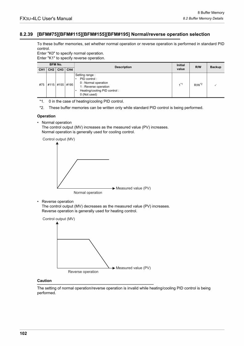
8 Buffer Memory8.2 Buffer Memory DetailsFX3U-4LC User's Manual
8.2.39 [BFM#75][BFM#115][BFM#155][BFM#195] Normal/reverse operation selection
To these buffer memories, set whether normal operation or reverse operation is performed in standard PIDcontrol.Enter "K0" to specify normal operation.Enter "K1" to specify reverse operation.
*1. 0 in the case of heating/cooling PID control.*2. These buffer memories can be written only while standard PID control is being performed.
Operation• Normal operation
The control output (MV) increases as the measured value (PV) increases.Normal operation is generally used for cooling control.
• Reverse operationThe control output (MV) decreases as the measured value (PV) increases.Reverse operation is generally used for heating control.
Caution
The setting of normal operation/reverse operation is invalid while heating/cooling PID control is being performed.
BFM No.Description Initial
value R/W BackupCH1 CH2 CH3 CH4
#75 #115 #155 #195
Setting range : • PID control :
0 : Normal operation1 : Reverse operation
• Heating/cooling PID control : 0 (Not used)
1*1 R/W*2
Control output (MV)
Normal operationMeasured value (PV)
Control output (MV)
Reverse operationMeasured value (PV)
102

8 Buffer Memory8.2 Buffer Memory DetailsFX3U-4LC User's Manual
1
Introduction
2
Specification
3
System
Configuration
4
Installation
5
Wiring
6
Introduction of Functions
7
Alarm
8
Buffer Mem
ory
9
Program
Examples
10
Troubleshooting
8.2.40 [BFM#76][BFM#116][BFM#156][BFM#196] Setting limiter upper limit
To these buffer memories, set the setting limiter upper limit for setting the upper limit of the set value (SV).→ For details on the set value (SV), refer to Subsection 8.2.15.
→ For details on the setting limiter lower limit, refer to Subsection 8.2.41.
Example of operation (When the input range is "-100 to +1300 C", the setting limiter upper limit is "1000 C" and the settinglimiter lower limit is "0 C")
Caution
• When handling numbers containing decimal places, multiply the set value by 10.• If a value outside the setting limiter range is entered, the set value range error flag (b1) turns ON. If the
setting limiter upper limit or setting limiter lower limit becomes outside the input range due to a change of the input type, the set value range error flag (b1) turns ON.When changing the input type, make sure that the setting limiter upper limit and lower limit do not exceed the input range.
→ For details on the input type, refer to Subsection 8.2.52.→ For details on the flag, refer to Subsection 8.2.1.
8.2.41 [BFM#77][BFM#117][BFM#157][BFM#197] Setting limiter lower limit
To these buffer memories, set the setting limiter lower limit for setting the lower limit of the set value (SV).→ For details on the set value (SV), refer to Subsection 8.2.15.
→ For an operation example of the setting limiter lower limit, refer to Subsection 8.2.40.→ For details on the setting limiter upper limit, refer to Subsection 8.2.40.
Caution
• When handling numbers containing decimal places, multiply the set value by 10.• If a value outside the setting limiter range is entered, the set value range error flag (b1) turns ON. If the
setting limiter upper limit or setting limiter lower limit becomes outside the input range due to a change of the input type, the set value range error flag (b1) turns ON.When changing the input type, make sure that the setting limiter upper limit and lower limit do not exceed the input range.
→ For details on the input type, refer to Subsection 8.2.52.→ For details on the flag, refer to Subsection 8.2.1.
BFM No.Description Initial
value R/W BackupCH1 CH2 CH3 CH4
#76 #116 #156 #196
Setting range : • Internal temperature input :
"Setting limiter lower limit + 1" to "Input range upper limit"• Internal micro voltage :
"Setting limiter lower limit + 1" to "Scaling range upper limit" • External input :
"Setting limiter lower limit + 1" to "External input range upper limit"
1300 R/W
BFM No.Description Initial
value R/W BackupCH1 CH2 CH3 CH4
#77 #117 #157 #197
Setting range : • Internal temperature input :
"Input range lower limit" to "Setting limiter upper limit -1"• Internal micro voltage :
"Scaling range lower limit" to "Setting limiter upper limit -1"• External input :
"External input range lower limit" to "Setting limiter upper limit -1"
-100 R/W
Setting limiter lower limit Setting limiter upper limit
Set value (SV) setting rangeInput range lower limit Input range upper limit
0 1000
-100 1300
CC
C C
103

8 Buffer Memory8.2 Buffer Memory DetailsFX3U-4LC User's Manual
8.2.42 [BFM#78][BFM#118][BFM#158][BFM#198] Loop breaking alarm judgement time
To these buffer memories, enter the loop breaking alarm judgment time.The loop breaking alarm function starts to detect the variation of the measured value (PV), at every loopbreaking alarm judgment time when the output becomes more than 100% (or the output limiter upper limit) orless than 0% (or the output limiter lower limit), then sets to ON the loop breaking alarm when judging thatthere is an abnormality in the control loop.
→ For details on the loop breaking alarm function, refer to Section 6.12.
*1. 0 in the case of heating/cooling PID control.*2. These buffer memories can be written only while standard PID control is being performed.
OperationThe loop breaking alarm is issued in the following cases.• PID control (reverse operation)
• PID control (normal operation)
*2. The variation range for loop breaking alarm judgment is fixed as follows, and cannot be changed.2.0 C for internal temperature input 0.2% of the scaling span for internal micro voltage input 0.2% of the external input span for external input
Caution
• The loop breaking alarm function judges abnormalities in the control loop, but cannot detect positions in which abnormalities occur. Check each part of the control system in turn.
• When the AT (auto tuning) function is completed, the loop breaking alarm judgement time is automatically set to the integral time result multiplied by 2.
• Set the time in which the measured increments changes by 2.0 C or 0.2% of the span or longer as the loop breaking alarm judgment time.If the loop breaking alarm judgement time is too short or is not suitable to control targets, the loop breaking alarm may repeatedly turn on and off or may not turn ON. In such a case, change the loop breaking alarm judgement time in accordance with the situation.
• In heating/cooling PID control, the loop breaking alarm function is disabled.• While AT (auto tuning) is performed, the loop breaking alarm function is disabled.• When "0" is entered, the loop breaking alarm function is disabled.
BFM No.Description Initial
value R/W BackupCH1 CH2 CH3 CH4
#78 #118 #158 #198
Setting range : • PID control :
0 to 7200 (sec.)• Heating/cooling PID control :
0 (Not used)
480*1 R/W*2
When output is less than 0% or output limiter lower limit
When measured value (PV) does not decrease at least by loop breaking changecriteria*2 within loop breaking alarm judgement time, an alarm is issued.
When output is more than 100% or output limiter upper limit
When measured value (PV) does not increase at least by loop breaking changecriteria*2 within loop breaking alarm judgement time, an alarm is issued.
When output is less than 0% or output limiter lower limit
When measured value (PV) does not decrease at leas by loop breaking changecriteria*2 within loop breaking alarm judgement time, an alarm is issued.
When output is more than 100% or output limiter upper limit
When measured value (PV) does not increase at least by loop breaking changecriteria*2 within loop breaking alarm judgement time, an alarm is issued.
104

8 Buffer Memory8.2 Buffer Memory DetailsFX3U-4LC User's Manual
1
Introduction
2
Specification
3
System
Configuration
4
Installation
5
Wiring
6
Introduction of Functions
7
Alarm
8
Buffer Mem
ory
9
Program
Examples
10
Troubleshooting
8.2.43 [BFM#79][BFM#119][BFM#159][BFM#199] Loop breaking alarm dead zone
Set the loop breaking alarm judgement time.The loop breaking alarm function may issue alarms caused by disturbances (effect of another heat source,etc.) even if there is no abnormality in the control system. In order to prevent such alarms, by setting the loopbreaking alarm dead zone, the region in which the alarm function is disabled (non-alarm status region) can beset.For example, if the loop breaking alarm dead zone is set to "10 C", 10 C above the set value (SV) and 10 Cbelow the set value (SV) are treated as the non-alarm status region (width of 20 C in total).
→ For details on the loop breaking alarm function, refer to Section 6.12.
*1. Input span for internal temperature inputScaling span for internal micro voltage inputExternal input span for external input
*2. When the span exceeds 32767, the setting range is from 0 to 32767.*3. These buffer memories can be written only while standard PID control is being performed.
Example of operation
*4. While the temperature is rising : Alarm status regionWhile the temperature is decreasing : Non-alarm status region
*5. While the temperature is rising : Non-alarm status regionWhile the temperature is decreasing : Alarm status region
*6. Loop breaking alarm dead zone operation gap 0.8 C for internal temperature input 0.8% of the scaling span for internal micro voltage input 0.8% of the external input span for external input
Caution
• When handling numbers containing decimal places, multiply the set value by 10.• While the measured value (PV) is located within the non-alarm region, alarm is not issued even if the alarm
condition is satisfied.• In heating/cooling PID control, the loop breaking alarm dead zone is invalid.
BFM No.Description Initial
value R/W BackupCH1 CH2 CH3 CH4
#79 #119 #159 #199
Setting range : • PID control :
0 to Input span*1*2 (0 : Disabled)• Heating/cooling PID control :
0 (Not used)
0 R/W*3
Alarm status region Alarm status region
LBD operation gap*5 LBD operation gap*5Non-alarm status region
Temperature fall Temperature riseSet value (SV)
*3*4
LBD set value
Loop breakingalarm function
Loop breakingalarm function
OFF
ON
105
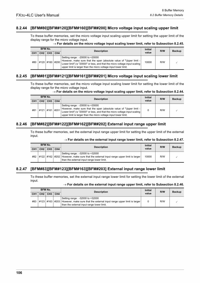
8 Buffer Memory8.2 Buffer Memory DetailsFX3U-4LC User's Manual
8.2.44 [BFM#80][BFM#120][BFM#160][BFM#200] Micro voltage input scaling upper limit
To these buffer memories, set the micro voltage input scaling upper limit for setting the upper limit of thedisplay range for the micro voltage input.
→ For details on the micro voltage input scaling lower limit, refer to Subsection 8.2.45.
8.2.45 [BFM#81][BFM#121][BFM#161][BFM#201] Micro voltage input scaling lower limit
To these buffer memories, set the micro voltage input scaling lower limit for setting the lower limit of thedisplay range for the micro voltage input.
→ For details on the micro voltage input scaling upper limit, refer to Subsection 8.2.44.
8.2.46 [BFM#82][BFM#122][BFM#162][BFM#202] External input range upper limit
To these buffer memories, set the external input range upper limit for setting the upper limit of the externalinput.
→ For details on the external input range lower limit, refer to Subsection 8.2.47.
8.2.47 [BFM#83][BFM#123][BFM#163][BFM#203] External input range lower limit
To these buffer memories, set the external input range lower limit for setting the lower limit of the externalinput.
→ For details on the external input range upper limit, refer to Subsection 8.2.46.
BFM No.Description Initial
value R/W BackupCH1 CH2 CH3 CH4
#80 #120 #160 #200
Setting range : -20000 to +20000However, make sure that the span (absolute value of "Upper limit -Lower limit") is "20000" or less, and that the micro voltage input scalingupper limit is larger than the micro voltage input lower limit.
10000 R/W
BFM No.Description Initial
value R/W BackupCH1 CH2 CH3 CH4
#81 #121 #161 #201
Setting range : -20000 to +20000However, make sure that the span (absolute value of "Upper limit -Lower limit") is "20000" or less, and that the micro voltage input scalingupper limit is larger than the micro voltage input lower limit.
0 R/W
BFM No.Description Initial
value R/W BackupCH1 CH2 CH3 CH4
#82 #122 #162 #202Setting range : -32000 to +32000However, make sure that the external input range upper limit is largerthan the external input range lower limit.
10000 R/W
BFM No.Description Initial
value R/W BackupCH1 CH2 CH3 CH4
#83 #123 #163 #203Setting range : -32000 to +32000However, make sure that the external input range upper limit is largerthan the external input range lower limit.
0 R/W
106

8 Buffer Memory8.2 Buffer Memory DetailsFX3U-4LC User's Manual
1
Introduction
2
Specification
3
System
Configuration
4
Installation
5
Wiring
6
Introduction of Functions
7
Alarm
8
Buffer Mem
ory
9
Program
Examples
10
Troubleshooting
8.2.48 [BFM#84][BFM#124][BFM#164][BFM#204] External output range upper limit
To these buffer memories, set the external output range upper limit for setting the upper limit of the externaloutput.
→ For details on the external output range lower limit, refer to Subsection 8.2.49.
8.2.49 [BFM#85][BFM#125][BFM#165][BFM#205] External output range lower limit
To these buffer memories, set the external output range lower limit for setting the lower limit of the externaloutput.
→ For details on the external output range upper limit, refer to Subsection 8.2.48.
BFM No.Description Initial
value R/W BackupCH1 CH2 CH3 CH4
#84 #124 #164 #204Setting range : -32000 to +32000However, make sure that the external output range upper limit is largerthan the external output range lower limit.
10000 R/W
BFM No.Description Initial
value R/W BackupCH1 CH2 CH3 CH4
#85 #125 #165 #205Setting range : -32000 to +32000However, make sure that the external output range upper limit is largerthan the external output range lower limit.
0 R/W
107

8 Buffer Memory8.2 Buffer Memory DetailsFX3U-4LC User's Manual
8.2.50 [BFM#86][BFM#126][BFM#166][BFM#206] Transistor output selection
To these buffer memories, set the function of transistor outputs built into the 4LC.Available transistor output functions vary depending on the control mode setting.
→ For details on the control mode switch, refer to Section 6.2.→ For details on the transistor output selection function, refer to Section 6.3.
Transistor output selection
*1. When selecting the control mode "4" or "5", use external output for CH2 and CH4.
Caution
It is not possible to change the setting while control is being performed. If the setting is changed while control is being performed, the contents of setting are reflected when control is stopped.
BFM No.Description Initial
value R/W BackupCH1 CH2 CH3 CH4
#86 #126 #166 #206 Setting range : 0 to 7 (Refer to the following) 0 R/W
Transistor output
selection set value
Control mode
0, 1 : PID control(Internal output)
2, 3 : PID control(External output)
4, 5 : Heating/cooling PID control
(Internal output)*1
6, 7 : Heating/cooling PID control
(External output)
0
OUT1 CH1 control output Normally OFF CH1 heating control output Normally OFF
OUT2 CH2 control output Normally OFF CH1 cooling control output Normally OFF
OUT3 CH3 control output Normally OFF CH3 heating control output Normally OFF
OUT4 CH4 control output Normally OFF CH3 cooling control output Normally OFF
1
OUT1 CH1 control output CH1 control output CH1 heating control output CH1 heating control output
OUT2 CH2 control output CH2 control output CH1 cooling control output CH2 heating control output
OUT3 CH3 control output CH3 control output CH3 heating control output CH3 heating control output
OUT4 CH4 control output CH4 control output CH3 cooling control output CH4 heating control output
2
OUT1 CH1 control output CH1 control output CH1 heating control output CH1 cooling control output
OUT2 CH2 control output CH2 control output CH1 cooling control output CH2 cooling control output
OUT3 CH3 control output CH3 control output CH3 heating control output CH3 cooling control output
OUT4 CH4 control output CH4 control output CH3 cooling control output CH4 cooling control output
3
OUT1 CH1 control output CH1 alarm 1 state CH1 heating control output CH1 alarm 1 state
OUT2 CH2 control output CH2 alarm 1 state CH1 cooling control output CH2 alarm 1 state
OUT3 CH3 control output CH3 alarm 1 state CH3 heating control output CH3 alarm 1 state
OUT4 CH4 control output CH4 alarm 1 state CH3 cooling control output CH4 alarm 1 state
4
OUT1 CH1 control output CH1 alarm 2 state CH1 heating control output CH1 alarm 2 state
OUT2 CH2 control output CH2 alarm 2 state CH1 cooling control output CH2 alarm 2 state
OUT3 CH3 control output CH3 alarm 2 state CH3 heating control output CH3 alarm 2 state
OUT4 CH4 control output CH4 alarm 2 state CH3 cooling control output CH4 alarm 2 state
5
OUT1 CH1 control output CH1 alarm 3 state CH1 heating control output CH1 alarm 3 state
OUT2 CH2 control output CH2 alarm 3 state CH1 cooling control output CH2 alarm 3 state
OUT3 CH3 control output CH3 alarm 3 state CH3 heating control output CH3 alarm 3 state
OUT4 CH4 control output CH4 alarm 3 state CH3 cooling control output CH4 alarm 3 state
6
OUT1 CH1 control output CH1 alarm 4 state CH1 heating control output CH1 alarm 4 state
OUT2 CH2 control output CH2 alarm 4 state CH1 cooling control output CH2 alarm 4 state
OUT3 CH3 control output CH3 alarm 4 state CH3 heating control output CH3 alarm 4 state
OUT4 CH4 control output CH4 alarm 4 state CH3 cooling control output CH4 alarm 4 state
7
OUT1 CH1 control output CH1 loop breaking alarm state CH1 heating control output Normally OFF
OUT2 CH2 control output CH2 loop breaking alarm state CH1 cooling control output Normally OFF
OUT3 CH3 control output CH3 loop breaking alarm state CH3 heating control output Normally OFF
OUT4 CH4 control output CH4 loop breaking alarm state CH3 cooling control output Normally OFF
108

8 Buffer Memory8.2 Buffer Memory DetailsFX3U-4LC User's Manual
1
Introduction
2
Specification
3
System
Configuration
4
Installation
5
Wiring
6
Introduction of Functions
7
Alarm
8
Buffer Mem
ory
9
Program
Examples
10
Troubleshooting
8.2.51 [BFM#87][BFM#127][BFM#167][BFM#207] ST (startup tuning) execution command
To these buffer memories, set stop or execution of startup tuning.Write "K0" to stop startup tuning.Write "K1" to perform startup tuning.
→ For details on the ST (Startup tuning), refer to Section 6.9.
Caution
• These buffer memories are valid only in standard PID control.• If control is started while both the AT execution command buffer memory and the ST execution command
buffer memory are set to "1", auto tuning is started.• Startup tuning is not started if the conditions for performing startup tuning are not satisfied.
→ For details on the conditions for performing ST (startup tuning), refer to Subsection 6.9.2.
BFM No.Description Initial
value R/W BackupCH1 CH2 CH3 CH4
#87 #127 #167 #207 0 : Stops ST (startup turning)1 : Performs ST (startup turning) 0 R/W -
109

8 Buffer Memory8.2 Buffer Memory DetailsFX3U-4LC User's Manual
8.2.52 [BFM#208][BFM#214][BFM#220][BFM#226] Input type
To these buffer memories, set the input type.
*1. These buffer memories can be written only while control is stopped.
Input type
Caution
• It is not possible to change the setting while control is being performed. If the setting is changed while control is being performed, the contents of setting are reflected when control is stopped.
• When changing the input type, change the setting limiter values also so that the setting limiter values are within the input range. In addition, it is possible to initialize the data to the setting limiter values corresponding to the newly selected input type by writing "K2" to the initialization command (BFM #255).
→ For details on the setting limiter upper limit, refer to Subsection 8.2.40.→ For details on the setting limiter lower limit, refer to Subsection 8.2.41.
BFM No.Description Initial
value R/W BackupCH1 CH2 CH3 CH4
#208 #214 #220 #226 Input type (Refer to the following) 2 R/W*1
Setvalue
Input type Input range Unit Set
valueInput type Input range Unit
0
K
-200.0 to 200.0 0.1 C 24B
0 to 1800 C
1 -100.0 to 400.0 0.1 C 25 0 to 3000 F
2 -100 to 1300 C 26N
0 to 1300 C
3 -100 to 800 F 27 0 to 2300 F
4 -100 to 2400 F 28PLII
0 to 1200 C
5
J
-200.0 to 200.0 0.1 C 29 0 to 2300 F
6 -100.0 to 400.0 0.1 C 30 W5Re/W26Re
0 to 2300 C
7 -100.0 to 800.0 0.1 C 31 0 to 3000 F
8 -100 to 1200 C 32U
-200.0 to 600.0 0.1 C
9 -100 to 1600 F 33 -300.0 to 700.0 0.1 F
10 -100 to 2100 F 34L
0.0 to 900.0 0.1 C
11R
0 to 1700 C 35 0 to 1600 F
12 0 to 3200 F 36
Jpt100
-50.0 to 150.0 0.1 C
13S
0 to 1700 C 37 -200.0 to 500.0 0.1 C
14 0 to 3200 F 38 -300.0 to 300.0 0.1 F
15
E
-200.0 to 200.0 0.1 C 39 -300 to 900 F
16 0 to 1000 C 40
Pt100
-50.0 to 150.0 0.1 C
17 0 to 1800 F 41 -200.0 to 600.0 0.1 C
18
T
-200.0 to 200.0 0.1 C 42 -300.0 to 300.0 0.1 F
19 -200.0 to 400.0 0.1 C 43 -300 to 1100 F
20 0.0 to 400.0 0.1 C 44Pt1000
-200.0 to 650.0 0.1 C
21 -300.0 to 400.0 0.1 F 45 -328 to 1184 F
22 -300.0 to 700.0 0.1 F 46 Micro voltage input
0 to 10 mV
23 0.0 to 700.0 0.1 F 47 0 to 100 mV
110

8 Buffer Memory8.2 Buffer Memory DetailsFX3U-4LC User's Manual
1
Introduction
2
Specification
3
System
Configuration
4
Installation
5
Wiring
6
Introduction of Functions
7
Alarm
8
Buffer Mem
ory
9
Program
Examples
10
Troubleshooting
8.2.53 [BFM#209 to #212][BFM#215 to #218][BFM#221 to #224][BFM#227 to #230]Alarm mode setting
The 4LC is equipped with 14 types of alarms. Four types of alarms (alarm 1 to alarm 4) are available in eachchannel in accordance with the application.Set the alarm type by writing the alarm mode (0 to 14) to the alarm mode setting buffer memories for alarms 1to 4 (each channel).Values of alarms 1 to 4 can be set using the alarm set value buffer memories, and the alarm status can bechecked in the status of alarm bits (b4 to b7) for alarms 1 to 4 of the event buffer memory.
→ For details on the alarm function, refer to Chapter 7.→ For details on the event, refer to Subsection 8.2.2.
→ For details on the alarm setting value, refer to Subsection 8.2.16.
*1. These buffer memories can be written only while control is stopped.
Alarm mode (0 to 14)
BFM No.Description Initial
value R/W BackupCH1 CH2 CH3 CH4Alarm 1 mode setting
#209 #215 #221 #227 Setting range : 0 to 14 (Refer to the following) 0 R/W*1
Alarm 2 mode setting
#210 #216 #222 #228 Setting range : 0 to 14 (Refer to the following) 0 R/W*1
Alarm 3 mode setting
#211 #217 #223 #229 Setting range : 0 to 14 (Refer to the following) 0 R/W*1
Alarm 4 mode setting
#212 #218 #224 #230 Setting range : 0 to 14 (Refer to the following) 0 R/W*1
Alarm mode Alarm type Description
0 Alarm function OFF Alarm function is disabled.
1 Upper limit input value alarm When measured value (PV) is more than alarm set value, an alarm is issued.
2 Lower limit input value alarm When measured value (PV) is less than alarm set value, an alarm is issued.
3 Upper limit deviation alarm When deviation (= Measured value (PV) - Set value (SV)) is more than alarm setvalue, an alarm is issued.
4 Lower limit deviation alarm When deviation (= Measured value (PV) - Set value (SV)) is less than alarm setvalue, an alarm is issued.
5 Upper/lower limit deviation When absolute deviation (= Measured value (PV) - Set value (SV)) is more thanalarm set value, an alarm is issued.
6 Range alarm When absolute deviation (= Measured value (PV) - Set value (SV)) is less thanalarm set value, an alarm is issued.
7 Upper limit input value alarm withwait
When measured value (PV) is more than alarm set value, an alarm is issued.However, when control is started the measured value is ignored.
8 Lower limit input value alarm withwait
When measured value (PV) is less than alarm set value, an alarm is issued.However, when control is started the measured value is ignored.
9 Upper limit deviation value alarmwith wait
When deviation (= Measured value (PV) - Set value (SV)) is more than alarm setvalue, an alarm is issued.However, when control is started the measured value is ignored.
10 Lower limit deviation value alarmwith wait
When deviation (= Measured value (PV) - Set value (SV)) is less than alarm setvalue, an alarm is issued.However, when control is started the measured value is ignored.
11 Upper/lower limit deviation valuealarm with wait
When absolute deviation (= Measured value (PV) - Set value (SV)) is more thanalarm set value, an alarm is issued.However, when control is started the measured value is ignored.
12 Upper limit deviation value alarmwith re-wait
When deviation (= Measured value (PV) - Set value (SV)) is more than alarm setvalue, an alarm is issued.However, when control is started and when set value is changed the measuredvalue is ignored.
13 Lower limit deviation value alarmwith re-wait
When deviation (= Measured value (PV) - Set value (SV)) is less than alarm setvalue, an alarm is issued.However, when control is started and when set value is changed the measuredvalue is ignored.
111

8 Buffer Memory8.2 Buffer Memory DetailsFX3U-4LC User's Manual
Caution
It is not possible to change the setting while control is being performed.If the setting is changed while control is being performed, the contents of setting are reflected when control is stopped.
8.2.54 [BFM#232] Cooling method setting
To these buffer memories, set the cooling method for performing heating/cooling PID control.Select the cooling method among "air cooling type", "water cooling type" and "cooling gain linear type" inaccordance with the cooling unit.Because the cooling characteristics are considerably different between the air cooling method and the watercooling method, PID constants suitable to the cooling unit can be obtained by setting the cooling methodbefore starting auto tuning.The selected cooling method is applied to all channels.
→ For details on the cooling method, refer to Subsection 6.6.4.
*1. The cooling method can be written to BFM #232 when either GR1 or GR2 is set to heating/cooling PIDcontrol.
Caution
Set the cooling method before performing auto tuning because the setting affects arithmetic operation results of PID constants acquired by auto tuning.
14 Upper/lower limit deviation valuealarm with re-wait
When absolute deviation (= Measured value (PV) - Set value (SV)) is more thanalarm set value, an alarm is issued.However, when control is started and when set value is changed the measuredvalue is ignored.
BFM No.Description Initial
value R/W BackupCH1 CH2 CH3 CH4
#232
Setting range :• PID control :
0 (Not used)• Heating/cooling PID control :
0 : Air cooling type1 : Water cooling type2 : Cooling gain linear type
0 R/W*1
Alarm mode Alarm type Description
112

8 Buffer Memory8.2 Buffer Memory DetailsFX3U-4LC User's Manual
1
Introduction
2
Specification
3
System
Configuration
4
Installation
5
Wiring
6
Introduction of Functions
7
Alarm
8
Buffer Mem
ory
9
Program
Examples
10
Troubleshooting
8.2.55 [BFM#233] Alarm dead band setting
To these buffer memories, set the dead zone for alarms 1 to 4.The setting is applied to alarms 1 to 4 in all channels.When the measured value (PV) is around the alarm set value, the alarm status and non-alarm status may berepeated due to input fluctuations.By setting the alarm dead zone, it is possible to prevent repetitions of the alarm status and non-alarm status.
→ For details on the alarm function, refer to Chapter 7.→ For details on the measured value (PV), refer to Subsection 8.2.3.→ For details on the alarm setting value, refer to Subsection 8.2.16.→ For details on the alarm mode setting, refer to Subsection 8.2.53.
*1. Input span for internal temperature inputScaling span for internal micro voltage inputExternal input span for external input
Example of operation 1 (Upper limit input value alarm, Upper limit deviation alarm)
Example of operation 2 (Lower limit input value alarm, Lower limit deviation alarm)
BFM No.Description Initial
value R/W BackupCH1 CH2 CH3 CH4
#233 Setting range : 0 to 100 (0.0 to 10.0% of span)*1 10 R/W
Measured value (PV)
Alarm status
Non-alarm statusTime
Measured value (PV)
Dead zone
Alarm status
Alarm set value
Measured value (PV)
Alarm status
Non-alarm statusTime
Measured value (PV)
Dead zone
Alarm status
Alarm set value
113

8 Buffer Memory8.2 Buffer Memory DetailsFX3U-4LC User's Manual
Example of operation 3 (Upper/lower limit deviation)
Caution
Handling numbers containing decimal places. The set value should be the actual value multiplied by 10.
8.2.56 [BFM#234] Alarm delay count
To this buffer memory, set the number of times of alarm delay for alarms 1 to 4.The setting is applied to alarms 1 to 4 in all channels.The alarm delay function keeps the non-alarm status until the number of times of input sampling exceeds thepreset number of times of alarm delay after the deviation between the measured value (PV) and the set value(SV) reaches the alarm set value.If the deviation remains in the alarm range until the number of times of input sampling exceeds the number oftimes of alarm delay, an alarm is issued.The input sampling period is 0.25 sec for the number of times of alarm delay.
→ For details on the alarm function, refer to Chapter 7.→ For details on the measured value (PV), refer to Subsection 8.2.3.
→ For details on the set value (SV), refer to Subsection 8.2.15.→ For details on the alarm setting value, refer to Subsection 8.2.16.→ For details on the alarm mode setting, refer to Subsection 8.2.53.
Example of operation (When the number of alarm delays, is set to 5 times)
BFM No.Description Initial
value R/W BackupCH1 CH2 CH3 CH4
#234 Setting range : 0 to 30000 0 R/W
Time
Measured value (PV)
Dead zone
Measured value (PV)
Dead zone
Alarm status
Alarm set value
Alarm set value
Set value (SV)
Alarm status
Non-alarm status
Time
Measured value (PV)Measured value (PV)
Input sampling
3 times 5 times
Alarm status
Alarm set value
Set value (SV)
Alarm status
Non-alarm status
114

8 Buffer Memory8.2 Buffer Memory DetailsFX3U-4LC User's Manual
1
Introduction
2
Specification
3
System
Configuration
4
Installation
5
Wiring
6
Introduction of Functions
7
Alarm
8
Buffer Mem
ory
9
Program
Examples
10
Troubleshooting
8.2.57 [BFM#235] Number of times of heater disconnection alarm delay/Number of times of current error detection when output is OFF delay
To this buffer memory, set the number of times of delay for detecting heater disconnection or detectingcurrent abnormality while the output is OFF.The setting is applied to all channels.If abnormality occurs continuously exceeding the preset number of times in the heater current measuredvalue or the current value while the output is OFF, an alarm is issued.The sampling period is 500ms for the heater current measured value and the current while the output is OFF.
→ For details on the heater disconnection alarm, refer to Section 6.11.→ For details on the heater current measured value, refer to Subsection 8.2.7.
8.2.58 [BFM#236] Temperature rise completion range setting
To this buffer memory, set the temperature rise completion range.The setting is applied to all channels.Set the temperature range in which temperature rise is regarded as completed for the set value (SV).When temperature rise is completed, the temperature rise completion flag (b15) of the event buffer memoryturns ON.By setting the temperature rise completion soak time, it is possible to delay the time until the temperature risecompletion flag turns ON after the measured value (PV) enters the temperature rise completion range.Set integers from 1 to 100 for temperature. (The setting value does not depend on input type.)
→ For details on the event, refer to Subsection 8.2.2.→ For details on the temperature rise completion soak time, refer to Subsection 8.2.59.
Example of operation
Caution
The temperature rise completion range is actually judged in a upper range portion and lower range portion of the set value (SV). Practically, the actual range width is doubled. (If the temperature rise completion range value is set to "10 C", 10 C above the set value and 10 C below the set value are treated as the temperature rise completion range (width of 20 C in total)).
BFM No.Description Initial
value R/W BackupCH1 CH2 CH3 CH4
#235 Setting range : 3 to 255 (times) 3 R/W
BFM No.Description Initial
value R/W BackupCH1 CH2 CH3 CH4
#236 Setting range : 1 to 100 (1 to 100 C/ F/digit) 10 R/W
(0.01% of span)+1
(0.01% of span)+1
completion rangeMeasured value (PV)
Temperature risecompleted flag
Set value (SV)
ON
OFF
Temperature rise
115

8 Buffer Memory8.2 Buffer Memory DetailsFX3U-4LC User's Manual
8.2.59 [BFM#237] Temperature rise completion soak time
To this buffer memory, set the temperature rise completion soak time.The setting is applied to all channels.When the measured value (PV) remains in the temperature rise completion range until the temperature risecompletion soak time is finished, the temperature rise completion flag (b15) of the event buffer memory turnsON.
→ For details on the event, refer to Subsection 8.2.2.→ For details on the temperature rise completion range, refer to Subsection 8.2.58.
Example of operation 1 (When the temperature rise completion soak time is set to any positive value)
Example of operation 2 (When the temperature rise completion soak time is set to "0")
Point
When the measured value (PV) is not stable even after it has reached the temperature rise completion range, the temperature rise completion soak time gives the waiting time for the judgment of temperature rise completion.
BFM No.Description Initial
value R/W BackupCH1 CH2 CH3 CH4
#237 Setting range : 0 to 3600 (sec.) 0 R/W
Temperature risecompletion range
Temperature risecompleted flag
Set value (SV)
Temperature risecompletion soak
time
Measured value(PV)
ON
OFF
Temperature risecompletion range
Temperature risecompleted flag
Set value (SV)
Measured value(PV)
ON
OFF
116
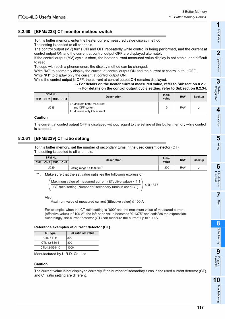
8 Buffer Memory8.2 Buffer Memory DetailsFX3U-4LC User's Manual
1
Introduction
2
Specification
3
System
Configuration
4
Installation
5
Wiring
6
Introduction of Functions
7
Alarm
8
Buffer Mem
ory
9
Program
Examples
10
Troubleshooting
8.2.60 [BFM#238] CT monitor method switch
To this buffer memory, enter the heater current measured value display method.The setting is applied to all channels.The control output (MV) turns ON and OFF repeatedly while control is being performed, and the current atcontrol output ON and the current at control output OFF are displayed alternately.If the control output (MV) cycle is short, the heater current measured value display is not stable, and difficultto read.To cope with such a phenomenon, the display method can be changed.Write "K0" to alternately display the current at control output ON and the current at control output OFF.Write "K1" to display only the current at control output ON.While the control output is OFF, the current at control output ON remains displayed.
→ For details on the heater current measured value, refer to Subsection 8.2.7.→ For details on the control output cycle setting, refer to Subsection 8.2.34.
Caution
The current at control output OFF is displayed without regard to the setting of this buffer memory while control is stopped.
8.2.61 [BFM#239] CT ratio setting
To this buffer memory, set the number of secondary turns in the used current detector (CT).The setting is applied to all channels.
*1. Make sure that the set value satisfies the following expression:
Reference examples of current detector (CT)
Manufactured by U.R.D. Co., Ltd.
Caution
The current value is not displayed correctly if the number of secondary turns in the used current detector (CT) and CT ratio setting are different.
BFM No.Description Initial
value R/W BackupCH1 CH2 CH3 CH4
#2380 : Monitors both ON current and OFF current1 : Monitors only ON current
0 R/W
BFM No.Description Initial
value R/W BackupCH1 CH2 CH3 CH4
#239 Setting range : 1 to 9999*1 800 R/W
CT type CT ratio set valueCTL-6-P-H 800
CTL-12-S36-8 800
CTL-12-S56-10 1000
CT ratio setting (Number of secondary turns in used CT)Maximum value of measured current (Effective value) × 1.1
≤ 0.1377
Also, Maximum value of measured current (Effective value) ≤ 100 A
For example, when the CT ratio setting is "800" and the maximum value of measured current (effective value) is "100 A", the left-hand value becomes "0.1375" and satisfies the expression. Accordingly, the current detector (CT) can measure the current up to 100 A.
117

8 Buffer Memory8.2 Buffer Memory DetailsFX3U-4LC User's Manual
8.2.62 [BFM#240, #241] Control mode switch
To these buffer memories, set the control type (standard PID control, two-position control, manual control,cascade control or heating/cooling control) and used inputs/outputs (external or internal) for each controlgroup.Control groups are classified into group 1 (CH1 and CH2) and group 2 (CH3 and CH4).The setting for control group 1 (GR1) is applied to both CH1 and CH2.The setting for control group 2 (GR2) is applied to both CH3 and CH4.
→ For details on the control mode, refer to Section 6.2.
*1. These buffer memories can be written only while control is stopped.
Control mode
• When internal input is selectedThe 4LC performs control using measured values detected through inputs built into the 4LC.
• When external input is selectedThe 4LC performs control using values stored in the external input value buffer memories (BFM#25 to BFM#28) without using inputs built into the 4LC.
• When internal output is selectedThe 4LC performs control using transistor outputs built into the 4LC. However, in heating/cooling PID control, the control output of CH2 and CH4 should use an external output.
• When external output is selectedThe 4LC performs control using values stored in the external output value monitor/heating external output value monitor buffer memories (BFM#32 to BFM#35) and cooling external output value monitor buffer memories (BFM#36 to BFM#39) without using transistor outputs built into the 4LC. The transistor output built into the 4LC is controllable when transistor output selections 1 and 2 are chosen. Additionally the outputs can also be used as alarm outputs.
→ For details on the external input value, refer to Subsection 8.2.8.→ For details on the external output value, refer to Subsection 8.2.11 or 8.2.12.
→ For details on the transistor output selection, refer to Subsection 8.2.50.
Caution
• It is not possible to change the setting while control is being performed.If the setting is changed while control is being performed, the contents of setting are changed when control is stopped.
• When changing the control mode, write "K2" to the initialization command (BFM #255) to initialize the related buffer memories to the values corresponding to the control mode.
BFM No.Description Initial
value R/W BackupCH1 CH2 CH3 CH4GR1 GR2
#240 #241 Setting range : 0 to 7 (Refer to the following) 0 R/W*1
Control mode Control type Input Output0 PID control
Two-position controlManual control
Cascade control
InternalInternal
1 External
2 InternalExternal
3 External
4Heating/cooling PID
controlTwo-position control
InternalInternal
5 External
6 InternalExternal
7 External
118
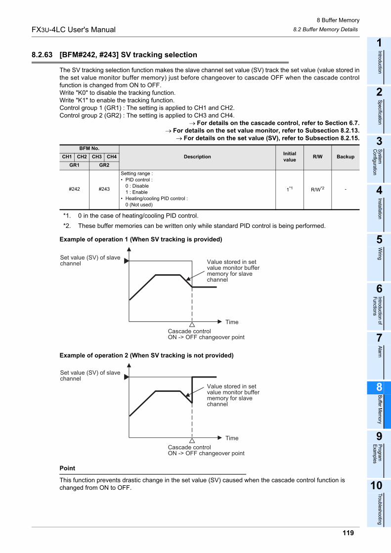
8 Buffer Memory8.2 Buffer Memory DetailsFX3U-4LC User's Manual
1
Introduction
2
Specification
3
System
Configuration
4
Installation
5
Wiring
6
Introduction of Functions
7
Alarm
8
Buffer Mem
ory
9
Program
Examples
10
Troubleshooting
8.2.63 [BFM#242, #243] SV tracking selection
The SV tracking selection function makes the slave channel set value (SV) track the set value (value stored inthe set value monitor buffer memory) just before changeover to cascade OFF when the cascade controlfunction is changed from ON to OFF.Write "K0" to disable the tracking function.Write "K1" to enable the tracking function.Control group 1 (GR1) : The setting is applied to CH1 and CH2.Control group 2 (GR2) : The setting is applied to CH3 and CH4.
→ For details on the cascade control, refer to Section 6.7.→ For details on the set value monitor, refer to Subsection 8.2.13.
→ For details on the set value (SV), refer to Subsection 8.2.15.
*1. 0 in the case of heating/cooling PID control.*2. These buffer memories can be written only while standard PID control is being performed.
Example of operation 1 (When SV tracking is provided)
Example of operation 2 (When SV tracking is not provided)
Point
This function prevents drastic change in the set value (SV) caused when the cascade control function is changed from ON to OFF.
BFM No.Description Initial
value R/W BackupCH1 CH2 CH3 CH4GR1 GR2
#242 #243
Setting range :• PID control :
0 : Disable1 : Enable
• Heating/cooling PID control :0 (Not used)
1*1 R/W*2 -
Cascade controlON -> OFF changeover point
Time
Set value (SV) of slavechannel Value stored in set
value monitor buffermemory for slavechannel
Cascade controlON -> OFF changeover point
Time
Set value (SV) of slavechannel
Value stored in setvalue monitor buffermemory for slavechannel
119

8 Buffer Memory8.2 Buffer Memory DetailsFX3U-4LC User's Manual
8.2.64 [BFM#244, #245] Cascade ON/OFF
Using these buffer memories, turn ON or OFF cascade control.Write "K0" to turn OFF cascade control.Write "K1" to turn ON cascade control.When cascade control is changed over from OFF to ON, the control output from the master channel ischanged over without bump. When cascade control is changed over from ON to OFF, the resulted operationvaries depending on the setting of the SV tracking selection buffer memory.Control group 1 (GR1) : The setting is applied to CH1 and CH2.Control group 2 (GR2) : The setting is applied to CH3 and CH4.
→ For details on the cascade control, refer to Section 6.7.→ For details on the SV tracking selection, refer to Subsection 8.2.64.
*1. These buffer memories can be written only while standard PID control is being performed.Caution
• Cascade control is disabled when heating/cooling PID control is selected.• Auto tuning and startup tuning are disabled while cascade control is being performed.
8.2.65 [BFM#246, #247] Cascade gain
To these buffer memories, set the gain used during cascade control when the control output (MV) from themaster channel is added to the cascade bias, converted into the full scale of the slave channel input range,and then converted into the cascade signal.Control group 1 (GR1) : The setting is applied to CH1 and CH2.Control group 2 (GR2) : The setting is applied to CH3 and CH4.
→ For details on the cascade control, refer to Section 6.7.→ For details on the cascade bias, refer to Subsection 8.2.66.
*1. These buffer memories can be written only while standard PID control is being performed.*2. 0 in the case of heating/cooling PID control.
Caution
Handling numbers containing decimal places. The set value should be the actual value multiplied by 1000.
BFM No.Description Initial
value R/W BackupCH1 CH2 CH3 CH4GR1 GR2
#244 #245
Setting range :• PID control :
0 : Cascade OFF1 : Cascade ON
• Heating/cooling PID control :0 (Not used)
0 R/W*1 -
BFM No.Description Initial
value R/W BackupCH1 CH2 CH3 CH4GR1 GR2
#246 #247
Setting range :• PID control :
-10000 to +10000 (-10.000 to +10.000 times)• Heating/cooling PID control :
0 (Not used)
1000*2 R/W*1
120

8 Buffer Memory8.2 Buffer Memory DetailsFX3U-4LC User's Manual
1
Introduction
2
Specification
3
System
Configuration
4
Installation
5
Wiring
6
Introduction of Functions
7
Alarm
8
Buffer Mem
ory
9
Program
Examples
10
Troubleshooting
8.2.66 [BFM#248, #249] Cascade bias
To these buffer memories, set the cascade bias added to the control output (MV) from the master channelduring cascade control.Control group 1 (GR1) : The setting is applied to CH1 and CH2.Control group 2 (GR2) : The setting is applied to CH3 and CH4.
→ For details on the cascade control, refer to Section 6.7.→ For details on the cascade gain, refer to Subsection 8.2.65.
*1. These buffer memories can be written only while standard PID control is being performed.Caution
Handling numbers containing decimal places. The set value should be the actual value multiplied by 10.
8.2.67 [BFM#250, #251] Cascade monitor
These buffer memories store the value from the master channel which is converted using the cascade gainand cascade bias.The value stored in a cascade monitor is as follows.
Cascade monitor value = [Master channel control output value (MV) cascade gain + cascade bias] slave channel of input span
Control group 1 (GR1) : The setting is applied to CH1 and CH2.Control group 2 (GR2) : The setting is applied to CH3 and CH4.
→ For details on the cascade control, refer to Section 6.7.→ For details on the cascade gain, refer to Subsection 8.2.65.→ For details on the cascade bias, refer to Subsection 8.2.66.
Caution
These buffer memories store "0" while cascade control is OFF.
BFM No.Description Initial
value R/W BackupCH1 CH2 CH3 CH4GR1 GR2
#248 #249
Setting range :• PID control :
-1000 to +1000 (-100.0% to +100.0%)• Heating/cooling PID control :
0 (Not used)
0 R/W*1
BFM No.Description Initial
value R/W BackupCH1 CH2 CH3 CH4GR1 GR2#250 #251 Display range : -32000 to +32000 0 R -
121

8 Buffer Memory8.2 Buffer Memory DetailsFX3U-4LC User's Manual
8.2.68 [BFM#252] Set value range error address
When a value written to each buffer memory is outside the setting range, the set value range error flag (b1)turns ON, and this buffer memory BFM#252 stores the buffer memory number where the error has occurred.The setting is applied to all channels.Check the setting range of the memory number where the error has occurred, set a normal value, and thenexecute the error reset command.
→ For details on the flag, refer to Subsection 8.2.1.→ For details on the error reset command, refer to Subsection 8.2.69.
Caution
• This buffer memory stores "0" when no error has occurred.• This buffer memory stores the lowest buffer memory number when two or more errors have occurred.
8.2.69 [BFM#253] Error reset command
Reset errors using this buffer memory.Write "K1" to reset existing errors.The contents of errors can be checked using flags.The setting is applied to all channels.
→ For details on the flag, refer to Subsection 8.2.1.→ For details on the set value range error address, refer to Subsection 8.2.68.
Caution
• Set "K1" for 0.25 sec or more to execute the error reset command.• This buffer memory (Error reset command) does not become "0" automatically after errors are reset.
Write "K0" to this buffer memory after errors are reset.
BFM No.Description Initial
value R/W BackupCH1 CH2 CH3 CH4
#252 0 : Normal1 to 255 : Setting error address 0 R -
BFM No.Description Initial
value R/W BackupCH1 CH2 CH3 CH4
#253 0 : Performs nothing1 : Resets errors 0 R/W -
122

8 Buffer Memory8.2 Buffer Memory DetailsFX3U-4LC User's Manual
1
Introduction
2
Specification
3
System
Configuration
4
Installation
5
Wiring
6
Introduction of Functions
7
Alarm
8
Buffer Mem
ory
9
Program
Examples
10
Troubleshooting
8.2.70 [BFM#254] Set value backup command
Back up the set values using this buffer memory.Write "K1" to write the set values of the backup target buffer memories to the EEPROM built into the 4LC.The setting is applied to all channels.The EEPROM stores initial values at shipment.The backup target buffer memories can be checked using the buffer memory list.
→ For details on the buffer memory list, refer to Section 8.1.
Example of operation
Explanation of operation1) When "K1" is written to BFM#254 (Set value backup command), the "Set value being backed up" flag
turns ON.When backup of the set values is completed, the "Set value being backed up" flag turns OFF.After that, write "0" (for setting to OFF) to BFM#254 (Set value backup command).
2) If BFM#254 (Set value backup command) is set to OFF while the "Set value being backed up" flag is ON,the "Set value backup error" flag turns ON. In this case, perform the operation described in 3).
3) If BFM#254 (Set value backup command) is set to OFF while the "Set value backup error" flag is ON, the"Set value being backed up" flag turns ON. When backup is normally completed, the "Set value beingbacked up" flag and "Set value backup error" flag turn OFF. After that, write "0" (for setting to OFF) toBFM#254 (Set value backup command).
→ For details on the flag, refer to Subsection 8.2.1.Point
When the power is turned ON, the 4LC transfers the contents of the EEPROM to the buffer memories for using them as the set values for control. Accordingly, if the set values are written once to the EEPROM, it is unnecessary from the next power ON to write the set values to the buffer memory. The 4LC can start control immediately when the control start/stop changeover buffer is set to "1: Starts control".
→ For details on the control start/stop changeover, refer to Subsection 8.2.9.Caution
• This buffer memory (Set value backup command) does not become "0" automatically after backup is completed.Write "K0" to this buffer memory after backup is completed.
• If the power is turned OFF once and ON again when a set value backup error has occurred, all data is reset to the initial value.
• The set values are not backed up when a set value range error has occurred.
BFM No.Description Initial
value R/W BackupCH1 CH2 CH3 CH4
#254 0 : Normal1 : Starts to write EEPROM 0 R/W -
Set value backupcommand (BFM#254)
Set value being backed upflag (BFM#0 b13)
Set value backup errorflag (BFM#0 b3)
K1
K0ON
OFFON
OFF
1) 3)2)
123

8 Buffer Memory8.2 Buffer Memory DetailsFX3U-4LC User's Manual
8.2.71 [BFM#255] Initialization command
Initialize the set values using this buffer memory.The initialization range varies depending on the set value.Write "K1" to initialize all buffer memories.Write "K2" to initialize buffer memories #48 to #207, #232 and #242 to #247 in accordance with the input type(in the case of internal input) and control mode. Write "K2" when changing the input type or control mode.The setting is applied to all channels.Buffer memories are not initialized when "K0" is written.
→ For details on the input type, refer to Subsection 8.2.52.→ For details on the control mode switch, refer to Subsection 8.2.62.
*1. These buffer memories can be written only while control is stopped.
Example of operation
Explanation of operation1) When "K1" or "K2" is written to BFM#255 (Initialization command), the set values are initialized.2) When initialization is completed, BFM#255 becomes "K0", and the "Initialization completed" flag turns ON
and remains ON for approximately 250ms.→ For details on the flag, refer to Subsection 8.2.1.
Caution
• Do not write or read buffer memories while the Initialization command flag is ON.• Initialization is disabled while control is being performed or while the set values are backed up.
BFM No.Description Initial
value R/W BackupCH1 CH2 CH3 CH4
#255
0 : Does not initialize buffer memories.1 : Initialize all buffer memories.2 : Initializes buffer memories BFM#48 to #207, #232 and #242 to
#247 in accordance with the input type (in the case of internalinput) and control mode.
0 R/W*1 -
Initialization command(BFM#255)
Initialization completedflag (BFM#0 b14)
K1 or K2
K0
ON
OFF
ON for approx.250ms
124

9 Program Examples
FX3U-4LC User's Manual
1
Introduction
2
Specification
3
System
Configuration
4
Installation
5
Wiring
6
Introduction of Functions
7
Alarm
8
Buffer Mem
ory
9
Program
Examples
10
Troubleshooting
9. Program Examples
STARTUP AND MAINTENANCE PRECAUTIONS• Do not touch any terminal while the PLC's power is on.
Doing so may cause electric shock or malfunctions.• Before cleaning or retightening terminals, cut off all phases of the power supply externally.
Failure to do so may cause electric shock.• Before modifying or disrupting the program in operation or running the PLC, carefully read through this manual and the associated
manuals and ensure the safety of the operation.An operation error may damage the machinery or cause accidents.
STARTUP AND MAINTENANCE PRECAUTIONS• Do not disassemble or modify the PLC.
Doing so may cause fire, equipment failures, or malfunctions.For repair, contact your local Mitsubishi Electric representative.
• Turn off the power to the PLC before attaching or detaching the following devices.Failure to do so may cause equipment failures or malfunctions.- Peripheral devices, display modules, expansion boards and special adapters- I/O extension units/blocks, FX Series terminal block and the special function units/blocks- Battery and memory cassette
125
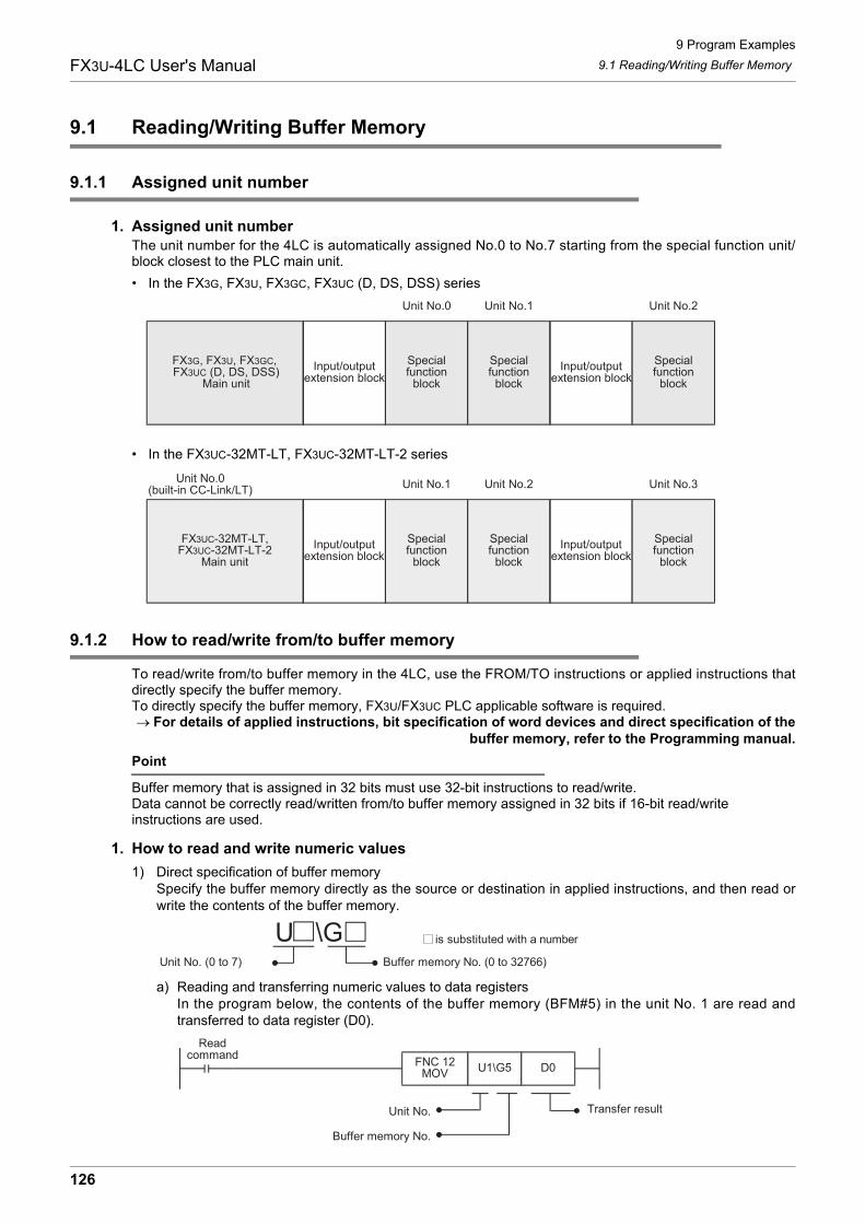
9 Program Examples9.1 Reading/Writing Buffer MemoryFX3U-4LC User's Manual
9.1 Reading/Writing Buffer Memory
9.1.1 Assigned unit number
1. Assigned unit numberThe unit number for the 4LC is automatically assigned No.0 to No.7 starting from the special function unit/block closest to the PLC main unit.• In the FX3G, FX3U, FX3GC, FX3UC (D, DS, DSS) series
• In the FX3UC-32MT-LT, FX3UC-32MT-LT-2 series
9.1.2 How to read/write from/to buffer memory
To read/write from/to buffer memory in the 4LC, use the FROM/TO instructions or applied instructions thatdirectly specify the buffer memory.To directly specify the buffer memory, FX3U/FX3UC PLC applicable software is required.→ For details of applied instructions, bit specification of word devices and direct specification of the
buffer memory, refer to the Programming manual.Point
Buffer memory that is assigned in 32 bits must use 32-bit instructions to read/write.Data cannot be correctly read/written from/to buffer memory assigned in 32 bits if 16-bit read/write instructions are used.
1. How to read and write numeric values1) Direct specification of buffer memory
Specify the buffer memory directly as the source or destination in applied instructions, and then read orwrite the contents of the buffer memory.
a) Reading and transferring numeric values to data registersIn the program below, the contents of the buffer memory (BFM#5) in the unit No. 1 are read andtransferred to data register (D0).
Input/outputextension block
Specialfunction
block
Specialfunction
blockInput/output
extension blockSpecialfunction
block
Unit No.0 Unit No.1 Unit No.2
FX3G, FX3U, FX3GC, FX3UC (D, DS, DSS)
Main unit
FX3UC-32MT-LT,FX3UC-32MT-LT-2
Main unit
Input/outputextension block
Specialfunction
block
Specialfunction
block
Input/outputextension block
Specialfunction
block
Unit No.0(built-in CC-Link/LT)
Unit No.1 Unit No.2 Unit No.3
Unit No. (0 to 7) Buffer memory No. (0 to 32766)
U \G is substituted with a number
Readcommand
FNC 12MOV
U1\G5 D0
Transfer resultUnit No.
Buffer memory No.
126

9 Program Examples9.1 Reading/Writing Buffer MemoryFX3U-4LC User's Manual
1
Introduction
2
Specification
3
System
Configuration
4
Installation
5
Wiring
6
Introduction of Functions
7
Alarm
8
Buffer Mem
ory
9
Program
Examples
10
Troubleshooting
b) Writing numeric values to the buffer memoryIn the program below, "K32,000" is written to the buffer memory (BFM#25) in the unit No. 1.
c) Writing the current value of data registers to the buffer memoryIn the program below, the current value of data register (D10) is written to the buffer memory(BFM#25) in the unit No. 1.
2) FROM/TO instructions (conventional method)Read and write the contents of the buffer memory using the FROM/TO instructions.a) Reading and transferring numeric values to data registers (FROM instruction)
In the program below, the contents of the buffer memory (BFM#5) in the unit No. 1 are read andtransferred to data registers (D0).
b) Writing numeric values to the buffer memory (TO instruction)In the program below, "K32,000" is written to the buffer memory (BFM#25) in the unit No. 1.
c) Writing the current value of data registers to the buffer memory (TO instruction)In the program below, the current value of data register (D10) is written to the buffer memory(BFM#25) in the unit No. 1.
Writecommand
FNC 12MOV
K32,000 U1\G25
Transfer source Buffer memory No.
Unit No.
Writecommand
FNC 12DMOV
D10 U1\G25
Transfer source Buffer memory No.
Unit No.
Readcommand
FNC 78FROM
K1 K5 D0 K1
Transfer destination
Number of transfer pointsUnit No.
Buffer memory No.
Writecommand
FNC 79TO
K1 K25 K32,000 K1
Transfer source
Number of transfer pointsUnit No.
Buffer memory No.
Writecommand
FNC 79TO
K1 K25 D10 K1
Transfer source
Number of transfer pointsUnit No.
Buffer memory No.
127

9 Program Examples9.1 Reading/Writing Buffer MemoryFX3U-4LC User's Manual
2. How to read and write the bit information such as flag and event1) Direct specification of buffer memory
Specify the buffer memory directly as the source in applied instructions, and read or write the contents.
a) Reading and transferring the bit information to auxiliary relaysIn the program below, the contents of the buffer memory (BFM#0) in the unit No. 1 are read andtransferred to auxiliary relays (M40 to M55).
b) Reading and transferring the bit information to data registersIn the program below, the contents of the buffer memory (BFM#0) in the unit No. 1 are read andtransferred to a data register (D200). The read bit information is used in bit specification of worddevices.
Unit No. (0 to 7) Buffer memory No. (0 to 32766)
U \G is substituted with a number
Readcommand
FNC 12MOV
U1\G0 K4M40
Transfer resultUnit No.
Buffer memory No.
M40
M41
M55
Readcommand
FNC 12MOV
U1\G0 D200
Transfer resultUnit No.
Buffer memory No.
D200.0
D200.1
D200.F
128

9 Program Examples9.1 Reading/Writing Buffer MemoryFX3U-4LC User's Manual
1
Introduction
2
Specification
3
System
Configuration
4
Installation
5
Wiring
6
Introduction of Functions
7
Alarm
8
Buffer Mem
ory
9
Program
Examples
10
Troubleshooting
c) Writing the bit information of auxiliary relays to the buffer memoryIn the program below, the ON/OFF status of auxiliary relays (M20 to M35) is written to the buffermemory (BFM#518) in the unit No. 0.
d) Writing the bit information stored in data registers to the buffer memoryIn the program below, the ON/OFF status of each bit of a data register (D201) is written to the buffermemory (BFM#518) in the unit No. 0. Each bit of the data register (D201) should be set to ON or OFFin advance by bit specification of word devices.
2) FROM/TO instructions (conventional method)Read the contents of the buffer memory using the FROM/TO instructions.a) Reading and transferring the bit information to auxiliary relays
In the program below, the contents of the buffer memory (BFM#0) in the unit No. 1 are read andtransferred to auxiliary relays (M40 to M55).
Writecommand FNC 12
MOVK4M20 U0\G518
Transfer source Buffer memory No.
Unit No.
M20
M21
M35
Writecommand FNC 12
MOVD201 U0\G518
Transfer source Buffer memory No.
Unit No.
D201.0
D201.1
D201.F
M40
M41
M55
Readcommand
FNC 78FROM
K1 K0 K4M40 K1
Transfer destination
Number of transfer pointsUnit No.
Buffer memory No.
129

9 Program Examples9.1 Reading/Writing Buffer MemoryFX3U-4LC User's Manual
b) Reading and transferring the bit information to data registersIn the program below, the contents of the buffer memory (BFM#0) in the unit No. 1 are read andtransferred to a data register (D200). The read bit information is used in bit specification of worddevices.
c) Writing the bit information of auxiliary relays to the buffer memoryIn the program below, the ON/OFF status of auxiliary relays (M20 to M35) is written to the buffermemory (BFM#518) in the unit No. 0.
d) Writing the bit information stored in data registers to the buffer memoryIn the program below, the ON/OFF status of each bit of a data register (D201) is written to the buffermemory (BFM#518) in the unit No. 0. Each bit of the data register (D201) should be set to ON or OFFin advance by bit specification of word devices.
D200.0
D200.1
D200.F
Readcommand
FNC 78FROM
K1 K0 D200 K1
Transfer destination
Number of transfer pointsUnit No.
Buffer memory No.
M20
M21
M35
Writecommand FNC 79
TOK0 K518 K4M20 K1
Transfer source
Number of transfer pointsUnit No.
Buffer memory No.
D201.0
D201.1
D201.F
Writecommand FNC 79
TOK0 K518 D201 K1
Transfer source
Number of transfer pointsUnit No.
Buffer memory No.
130

9 Program Examples9.2 Example of a Program for PID ControlFX3U-4LC User's Manual
1
Introduction
2
Specification
3
System
Configuration
4
Installation
5
Wiring
6
Introduction of Functions
7
Alarm
8
Buffer Mem
ory
9
Program
Examples
10
Troubleshooting
9.2 Example of a Program for PID Control
This section provides an example of a program for PID control.
9.2.1 System configuration
The system configuration shown below explains the example program.
9.2.2 Conditions of operation
The example program is set up with the following operation conditions.Initial values are used for conditions of operation other than the ones listed below. They are not shown in thisexample.Please modify the example program as needed.
ItemBFM No.
Conditions of operationCH1 CH2
Alarm 1 set value #49 #89 Upper limit deviation is set to "30.0 C"
Alarm 2 set value #50 #90 Lower limit deviation is set to "-30.0 C"
Operation mode #57 #97 Set "3 : Monitor + Alarm + Control" (initial value)
PID value
Proportional band (P) #58 #98
Set by auto tuningIntegral time (I) #60 #100
Derivative time (D) #61 #101
Control response parameter #62 #102 Set "1 : Medium"
Normal/reverse operation selection #75 #115 Set "1 : Reverse operation" (initial value)
Transistor output selection #86 #126 Set "0" (initial value)
Input type #208 #214 Set "1 : K type -100.0 to 400.0 C"
Alarm 1 mode setting #209 #215 Set "12 : Upper limit deviation alarm with re-wait"
Alarm 2 mode setting #210 #216 Set "13 : Lower limit deviation alarm with re-wait"
Temperature rise completion range setting #236 Set "3 C"
CT monitor method switch #238 Set "0 : ON current/OFF current" (initial value)
CT ratio setting #239 Set "800" (initial value)When a current detector (CTL-6-P-H) is used.
Control mode switch #240 Set "0" (initial value)
CH1 Measured value (PV)
CH1 Control output(MV)
CH1 Sensor(Type K
thermocouple)
Temperaturechamber
FX3U SeriesMain unit
FX3U-4LC(Unit No.0)
Solid state relay
CH1Currentdetector(CTL-6-P-H)
Heater
CH1 Heater currentmeasured value
CH2 Measured value (PV)
CH2 Control output(MV)
CH2 Sensor(Type K
thermocouple)
Temperaturechamber
Solid state relay
CH2Currentdetector(CTL-6-P-H)
Heater
CH2 Heater currentmeasured value
131

9 Program Examples9.2 Example of a Program for PID ControlFX3U-4LC User's Manual
9.2.3 Device assignments
Device assignments of the example program are assigned as follows.Device No. Contents of operation
X000 When X000 is turned on, parameters are initialized in the buffer memory.
X001 Initializes all data.
X002 Error reset is performed.
X003 PID control is started.
X004 Performs auto tuning (CH1).
X005 Performs auto tuning (CH2).
M0 to M15The state of a flag is read.The example program has included operation to carry out external output of the state of theerror present (b0).
M20 to M35The state of an event (CH1) is read.The example program has included operation to carry out external output of the state of theloop disconnection alarm (b8) of CH1.
M40 to M55The state of an event (CH2) is read.The example program has included operation to carry out external output of the state of theloop disconnection alarm (b8) of CH2.
D0 Setting value (CH1) is stored.
D1 Setting value (CH2) is stored.
D5 Measured value (CH1) is stored.
D6 Measured value (CH2) is stored.
D9 Control output value (CH1) is stored.
D10 Control output value (CH2) is stored.
D21 Heater current measured value (CH1) is stored.
D22 Heater current measured value (CH2) is stored.
D252 The value of a set value range error address is stored.
132

9 Program Examples9.2 Example of a Program for PID ControlFX3U-4LC User's Manual
1
Introduction
2
Specification
3
System
Configuration
4
Installation
5
Wiring
6
Introduction of Functions
7
Alarm
8
Buffer Mem
ory
9
Program
Examples
10
Troubleshooting
9.2.4 Sequence program
The sequence program for the example program with the FX3U-4LC as unit No. 0 is shown below. Changeunit No.0 to match the actual system configuration to be used.The FROM/TO instructions are used for read/write of buffer memory.
→ For details on the unit No., refer to Subsection 9.1.1.→ For details on the how to read/write from/to buffer memory, refer to Subsection 9.1.2.
→ For details on the system configuration, refer to Subsection 9.2.1.→ For details on the conditions of operation, refer to Subsection 9.2.2.
→ For details on the device assignments, refer to Subsection 9.2.3.M8002
K1000 D1
K0 K48 D0 K1
K0 K88 D1
SET M100
RST M100
K1
100.0 set to D0 and D1 as aset value.
Writes set values.
Control mode switch:0 (initial value)
Initialization command2(Write "K2" to BFM #255 when changing the input type or control mode.)
Input type selection:Type K -100.0 to 400.0
Control response parameter:1:Medium
Normal operation/reverseoperation:1:Reverse operation (initial value)
Loop breaking alarm dead zone
Transistor output selection:0 (initial value)
10.0
MOV
TO
TOM8000
M15X000
X000
M100 M14
Operation mode:3:Monitor+Alarm+Control(initial value)
Temperaturecontrol readyflag
Initialization completed flag
K0 K208 K1 K1 TO P
K0 K214 K1 K1 TO P
K0 K240 K0 K1 TO P
K0 K255 K2 K1 TO P
K0 K57 K3 K1 TO P
K0 K97 K3 K1 TO P
K0 K62 K1 K1 TO P
K0 K102 K1 K1 TO P
K0 K75 K1 K1 TO P
K0 K115 K1 K1 TO P
K0 K79 K100 K1 TO P
K0 K119 K100 K1 TO P
K0 K86 K0 K1 TO P
K0 K126 K0 K1 TO P
K1000 D0
MOV
To next pageTo next page
Initial pulse
RUN monitor
C
C
C
±
133

9 Program Examples9.2 Example of a Program for PID ControlFX3U-4LC User's Manual
M100
M8000
M14Alarm mode setting 1 (CH1):Upper limit deviation alarm with re-wait
Alarm mode setting 1 (CH2):Upper limit deviation alarm with re-wait
Alarm mode setting 2 (CH1):Lower limit deviation alarm with re-wait
Alarm mode setting 2 (CH2):Lower limit deviation alarm with re-wait
Temperature rise completion range:3
CT monitor method:ON current/OFF current (initial value)
CT ratio setting:800 (initial value)
Flag:BFM#0 M0 to M15
Alarm 1 set value:Upper limit deviation = +30.0
Alarm 2 set value:Lower limit deviation = -30.0
Initialization completed flag
RUN monitor
To next pageTo next page
From previous pageFrom previous page
C
C
C
→
Event (CH1):BFM#1 M20 to M35→
Event (CH2):BFM#2 M40 to M55→
Measured value:BFM#5 (CH1) BFM#6 (CH2)
D5D6
→→
Control output value:BFM#9 (CH1) BFM#10 (CH2)
D9 D10
→→
Heater current measured value:BFM#21 (CH1) BFM#22 (CH2)
D21D22→
→
Set value range error address:BFM#252 D252→
K0 K209 K12 K1 TO P
K0 K215 K12 K1 TO P
K0 K210 K13 K1 TO P
K0 K216 K13 K1 TO P
K0 K49 K300 K1 TO P
K0 K89 K300 K1 TO P
K0 K50 K-300 K1 TO P
K0 K90 K-300 K1 TO P
K0 K236 K3 K1 TO P
K0 K238 K0 K1 TO P
K0 K239 K800 K1 TO P
K0 K0 K4M0 K1FROM
K0 K1 K4M20 K1FROM
K0 K2 K4M40 K1FROM
K0 K5 D5 K2FROM
K0 K9 D9 K2FROM
K0 K21 D21 K2FROM
K0 K252 D252 K1FROM
134

9 Program Examples9.2 Example of a Program for PID ControlFX3U-4LC User's Manual
1
Introduction
2
Specification
3
System
Configuration
4
Installation
5
Wiring
6
Introduction of Functions
7
Alarm
8
Buffer Mem
ory
9
Program
Examples
10
Troubleshooting
Initializes all data.When X001 is set to ON, alldata is initialized.(When initialization is notnecessary, this line can beomitted.)
Error reset command.When X002 is set to ON, allerrors indicated by the flag(BFM#0) are reset.
Starts/stops control.When X003 turns OFF, controlstops.When X003 turns ON, controlstarts.In order to turn OFF the controloutput, this line is required andcannot be omitted.(The control output cannot beset to OFF by changeover from"RUN" to "STOP" of the PLCmain unit.)
In this example, only the AUTOmode is used.When changeover of the modeis necessary, write "K1" toBFM#54 and BFM#94 inaccordance with thechangeover condition.
When X004/X005 is set to ON,auto tuning is performed.Once auto tuning has started, itcontinues even if X004/X005 isset to OFF after that.When the flag (M34/M54) turnsOFF while auto tuning isperformed, it is judged that autotuning is completed. Then, "K0"is written to BFM#56/#96.Because of this, auto tuning canbe performed again.If auto tuning does not have tobe performed again, the uppertwo lines can be omitted.(M34 and M54 turn ON and offin accordance with the eventstatus.)
Y000 An error is present
CH1 Loop breaking alarm
CH2 Loop breaking alarm
Y001
Y002
Performs initialization
X001
Disables error reset
X002
Performs error reset
X002
Stops control
X003
Starts control
X003
Auto tuning isbeing performed (CH1)
M34
Auto tuning isbeing performed (CH2)
M54
Performs auto tuning (CH1)
X004
Performs auto tuning (CH2)
X005
An error is present
M0
CH1 Loop breaking alarm
M28
CH2 Loop breaking alarm
M48
M100
Initialization completed flag
M14
From previous pageFrom previous page
END
K0 K255 K1 K1 TO P
K0 K253 K0 K1 TO P
K0 K253 K1 K1 TO P
K0 K29 K0 K1 TO P
K0 K29 K1 K1 TO P
K0 K54 K0 K1 TO P
K0 K94 K0 K1 TO P
K0 K56 K0 K1 TO P
K0 K96 K0 K1 TO P
K0 K56 K1 K1 TO P
K0 K96 K1 K1 TO P
135

9 Program Examples9.3 Example of a Program for Heating/Cooling PID ControlFX3U-4LC User's Manual
9.3 Example of a Program for Heating/Cooling PID Control
This section provides an example of a program for heating/cooling PID control.
9.3.1 System configuration
The system configuration shown below explains the example program.
9.3.2 Conditions of operation
The example program set up with the following operation conditions.Initial values are used for conditions of operation other than the ones listed below. They are not shown in thisexample.Please add to the example of a program if needed.
ItemBFM No.
Conditions of operationCH1 CH2
Alarm 1 set value #49 - Upper limit deviation is set to "30.0 C"
Alarm 2 set value #50 - Lower limit deviation is set to "-30.0 C"
Operation mode #57 - Set "3 : Monitor + Alarm + Control" (initial value)
PID value
Heating proportional band (P) #58 -
Set by auto tuningCooling proportional
band (P) #59 -
Integral time (I) #60 -
Derivative time (D) #61 -
Control response parameter #62 - Set "1 : Medium"
Overlap/Dead band #63 - Set "0" (initial value)
Transistor output selection #86 - Set "0" (initial value)
Input range #208 - Set "1 : K type -100.0 to 400.0 C"
Alarm 1 mode setting #209 - Set "12 : Upper limit deviation alarm with re-wait"
Alarm 2 mode setting #210 - Set "13 : Lower limit deviation alarm with re-wait"
Cooling method setting #232 Set "0 : Air cooling"
Temperature rise completion range setting #236 Set "3 C"
CT monitor method switch #238 Set "0 : ON current/OFF current" (initial value)
CT ratio setting #239 Set "800" (initial value)When a current detector (CTL-6-P-H) is used.
Control mode switch #240 Set "4"
OUT1 Heating controloutput (MV)
CH1 Sensor(Type K thermocouple)
Temperaturechamber
FX3U SeriesMain unit
FX3U-4LC(Unit No.0)
Solid state relay
CH1Currentdetector(CTL-6-P-H)
Heater
CH1 Heater currentmeasured value
CH1 Measured value (PV)
OUT2 Cooling controloutput (MV)
Cooler
136

9 Program Examples9.3 Example of a Program for Heating/Cooling PID ControlFX3U-4LC User's Manual
1
Introduction
2
Specification
3
System
Configuration
4
Installation
5
Wiring
6
Introduction of Functions
7
Alarm
8
Buffer Mem
ory
9
Program
Examples
10
Troubleshooting
9.3.3 Device assignments
Device assignments of the example program are assigned as follows.Device No. Contents of operation
X000 When X000 is turned on, parameters are initialized in the buffer memory.
X001 Initializes all data.
X002 Error reset is performed.
X003 Heating/Cooling PID Control is started.
X004 Performs auto tuning (CH1).
M0 to M15The state of a flag is read.The example program includes operation to carry out external output of the state of the errorpresent (b0).
M20 to M35The state of an event (CH1) is read.The example program includes operation to carry out external output of the state of the loopdisconnection alarm (b8) of CH1.
D0 Setting value (CH1) is stored.
D5 Measured value (CH1) is stored.
D9 OUT1 Heating control output value is stored.
D14 OUT2 Cooling control output value is stored.
D21 Heater current measured value (CH1) is stored.
D252 The value of a set value range error address is stored.
137

9 Program Examples9.3 Example of a Program for Heating/Cooling PID ControlFX3U-4LC User's Manual
9.3.4 Sequence program
The sequence program for the example program with the FX3U-4LC as unit No. 0 is shown below. Changeunit No.0 to match the actual system configuration to be used.The FROM/TO instructions are used for read/write of buffer memory.
→ For details on the unit No., refer to Subsection 9.1.1.→ For details on the how to read/write from/to buffer memory, refer to Subsection 9.1.2.
→ For details on the system configuration, refer to Subsection 9.3.1.→ For details on the conditions of operation, refer to Subsection 9.3.2.
→ For details on the device assignments, refer to Subsection 9.3.3.
M8002100.0 set to D0 as a set value.
Writes set values.
Input type selection:Type K -100.0 to 400.0
Control mode switch:4
Initialization command2(Write "K2" to BFM #255 when changing the input type or control mode.)
Control response parameter:1:Medium
Overlap/dead band0 (initial value)
Operation mode:3:Monitor+Alarm+Control(initial value)
To next pageTo next page
Initial pulse
M8000
RUN monitor
M15X000
X000
M100 M14
Temperaturecontrol readyflag
Initialization completed flag
Transistor output selection:0 (initial value)
Alarm mode setting 1 (CH1):Upper limit deviation alarm with re-wait
Alarm mode setting 2:Lower limit deviation alarm with re-wait
Alarm 1 set value:Upper limit deviation = +30.0 C
Alarm 2 set value:Lower limit deviation = -30.0 C
C
CK0 K208 K1 K1 TO P
K0 K240 K4 K1 TO P
K0 K255 K2 K1 TO P
K0 K57 K3 K1 TO P
K0 K62 K1 K1 TO P
K0 K63 K0 K1 TO P
K0 K86 K0 K1 TO P
K0 K209 K12 K1 TO P
K0 K210 K13 K1 TO P
K0 K49 K300 K1 TO P
K0 K50 K-300 K1 TO P
MOV K1000 D0
SET M100
RST M100
K48 D0TO K0 K1
138

9 Program Examples9.3 Example of a Program for Heating/Cooling PID ControlFX3U-4LC User's Manual
1
Introduction
2
Specification
3
System
Configuration
4
Installation
5
Wiring
6
Introduction of Functions
7
Alarm
8
Buffer Mem
ory
9
Program
Examples
10
Troubleshooting
K0 K0 K4M0 K1
K0 K1 K4M20 K1
K0 K9 D9 K1
K0 K21 D21 K1
K0 K252 D252 K1
M8000FROM
FROM
FROM
FROM
FROM
To next pageTo next page
From previous pageFrom previous page
RUN monitor
K0 K232 K0 K1 TO P
K0 K5 D5 K1FROM
K0 K14 D14 K1FROM
K0 K238 K0 K1
K0 K236 K3 K1 TO P
TO P
K0 K239 K800 K1 TO P
M14M100
Initialization completed flag
Cooling method settingAir cooling type (initial value)
Temperature rise completion range:3 C
CT monitor method:ON current/OFF current (initial value)
CT ratio setting:800 (initial value)
Flag:BFM#0 → M0 to M15
Event (CH1):BFM#1 → M20 to M35
Measured value:BFM#5 (CH1) → D5
Heating control output value monitorBFM#9 → D9
Cooling control output value monitorBFM#14 → D14
Heater current measured value:BFM#21 (CH1) → D21
Set value range error address:BFM#252 → D252
139

9 Program Examples9.3 Example of a Program for Heating/Cooling PID ControlFX3U-4LC User's Manual
K0 K255 K1 K1
K0 K56 K0 K1
K0 K56 K1 K1
K0 K253 K0 K1
TO P
TO P
TO P
TO P
X002
Performs initialization
X001
Disables error reset
Auto tuning isbeing performed (CH1)
K0 K253 K1 K1 TO P
X002
Performs error reset
K0 K29 K0 K1 TO PStops control
K0 K29 K1 K1 TO P
X003
Starts control
X003
M34
X004
Performs auto tuning (CH1)
From previous pageFrom previous page
END
M0
An error is present
M24
CH1 Alarm1
Y000
Y001
An error is present
CH1 Alarm1
Initializes all data.When X001 is set to ON, alldata is initialized.(When initialization is notnecessary, this line can beomitted.)
Error reset command.When X002 is set to ON, allerrors indicated by the flag(BFM#0) are reset.
Starts/stops control.When X003 turns OFF, controlstops.When X003 turns ON, controlstarts.In order to turn OFF the controloutput, this line is required andcannot be omitted.(The control output cannot be set toOFF by changeover from "RUN" to"STOP" of the PLC main unit.)
When X004 is set to ON, autotuning is performed.Once auto tuning has started, itcontinues even if X004 is set toOFF after that.When the flag (M34) turns OFFwhile auto tuning is performed, it isjudged that auto tuning iscompleted. Then, "K0" is written toBFM#56.Because of this, auto tuning can beperformed again.If auto tuning does not have to beperformed again, the upper twolines can be omitted.(M34 turn ON and off in accordancewith the event status.)
140

10 Troubleshooting
FX3U-4LC User's Manual
1
Introduction
2
Specification
3
System
Configuration
4
Installation
5
Wiring
6
Introduction of Functions
7
Alarm
8
Buffer Mem
ory
9
Program
Examples
10
Troubleshooting
10. Troubleshooting
When a fault occurs, check the power supply voltage, the PLC main unit and the 4LC for loose terminalscrews, and examine the connectors for a defective contact.
STARTUP AND MAINTENANCE PRECAUTIONS• Do not touch any terminal while the PLC's power is on.
Doing so may cause electric shock or malfunctions.• Before cleaning or retightening terminals, cut off all phases of the power supply externally.
Failure to do so may cause electric shock.• Before modifying or disrupting the program in operation or running the PLC, carefully read through this manual and the associated
manuals and ensure the safety of the operation.An operation error may damage the machinery or cause accidents.
STARTUP AND MAINTENANCE PRECAUTIONS• Do not disassemble or modify the PLC.
Doing so may cause fire, equipment failures, or malfunctions.For repair, contact your local Mitsubishi Electric representative.
• Turn off the power to the PLC before attaching or detaching the following devices.Failure to do so may cause equipment failures or malfunctions.- Peripheral devices, display modules, expansion boards and special adapters- I/O extension units/blocks, FX Series terminal block and the special function units/blocks- Battery and memory cassette
141

10 Troubleshooting10.1 Troubleshooting ProcedureFX3U-4LC User's Manual
10.1 Troubleshooting Procedure
The flag (BFM#0) and event (BFM#1 to BFM#4) buffer memories store errors detected in the 4LC.You can check the contents of errors by monitoring the buffer memories using peripheral equipment orreading the contents of the buffer memories using the FROM instruction (or direct specification of buffermemories).
Flag (BFM#0)The following bits of the flag buffer memory (BFM#0) indicate errors.
Event (BFM#1)The following bits of the event buffer memory (BFM#1) indicate errors.
10.1.1 How to reset an error
After removing the cause of the error, reset the error by executing the error reset command.If the cause of the error remains, the error bit turns ON again.For details of the error reset command, refer to the following.
→ Refer to Subsection 8.2.69.
Bit Description Cause of errorb0 Error present Turns ON when an error among b1 to b10 below has occurred.
b1 Set value range errorTurns ON when data outside set range is written.The buffer memory number in which an error has been generated is storedin a set value range error address (BFM#252).
b2 24V DC power supply error Turns ON when driving power supply (24V DC) is not supplied.
b3 Set value backup error flag
Turns ON when an error has been caused by noise, when a failure hasoccurred in the 4LC, or when the backup command is set to OFF duringbackup.Turn the power ON again, and check for changes in the state. If noimprovement is obtained, consult your local Mitsubishi Electric representative.
b4 CH1 AT/ST abnormal end flag Turns ON when CH1 AT (auto tuning) or ST (startup tuning) abnormallyends.
b5 CH2 AT/ST abnormal end flag Turns ON when CH2 AT (auto tuning) or ST (startup tuning) abnormallyends.
b6 CH3 AT/ST abnormal end flag Turns ON when CH3 AT (auto tuning) or ST (startup tuning) abnormallyends.
b7 CH4 AT/ST abnormal end flag Turns ON when CH4 AT (auto tuning) or ST (startup tuning) abnormallyends.
b8 Adjustment data error Turns ON when an error has been caused by noise or when a failure hasoccurred in the 4LC.Turn the power ON again, and check for changes in the state. If noimprovement is obtained, consult your local Mitsubishi Electric representative.
b9 Cold contact temperature compensationdata error
b10 A/D converted value error
Bit Description Cause of errorb0 Input error (upper limit) Turns ON when input value is over scale.
b1 Input error (lower limit) Turns ON when input value is under scale.
b2 Cold contact temperature compensationdata error
Turns ON when an error has been caused by noise or when a failure hasoccurred in the 4LC.Turn the power ON again, and check for changes in the state. If noimprovement is obtained, consult your local Mitsubishi Electric representative.b3 A/D converted value error
b4 Alarm 1 Turns ON when an alarm 1 has occurred.
b5 Alarm 2 Turns ON when an alarm 2 has occurred.
b6 Alarm 3 Turns ON when an alarm 3 has occurred.
b7 Alarm 4 Turns ON when an alarm 4 has occurred.
b8 Loop breaking alarm Turns ON when a loop breaking alarm has occurred
b9 Heater disconnection alarm Turns ON when a heater disconnection alarm has occurred.
b10 Current error when output is OFF Turns ON when a current error occurs while output is OFF.
142

10 Troubleshooting10.2 Diagnostics on the PLC Main UnitFX3U-4LC User's Manual
1
Introduction
2
Specification
3
System
Configuration
4
Installation
5
Wiring
6
Introduction of Functions
7
Alarm
8
Buffer Mem
ory
9
Program
Examples
10
Troubleshooting
10.2 Diagnostics on the PLC Main Unit
The following describes some of the PLC errors from the LED lights on the PLC.For details related to the PLC main unit wiring, special auxiliary relays, and special data registers, refer to thefollowing respective manuals.
→ Refer to FX3G Hardware Edition.→ Refer to FX3U Hardware Edition.
→ Refer to FX3GC Hardware Edition.→ Refer to FX3UC Hardware Edition.
10.2.1 POWER (POW) LED [on/flashing/off]
The table below describes details for the LED statuses.
10.2.2 BATT (BAT) LED [on/off]
The table below describes details for the LED statuses.
Status PLC Status Error corrective action
ON Power of the specified voltage is beingsupplied to the power supply terminal. The power supply is normal.
Flicker
One of the following causes may haveoccurred.• Power and current of the specified
voltage is not being supplied to the powersupply terminal.
• Incorrect external wiring.• Internal errors in the PLC.
• Check the supply voltage.• After disconnecting cables other than the power cable, turn the power ON
again, and check for changes in the state. If no improvement is obtained,consult your local Mitsubishi Electric representative.
OFF
One of the following causes may have occurred.• The power supply is OFF.• Incorrect external wiring.• Power of the specified voltage is not
being supplied to the power supply terminal.
• The power cable is broken.
• If the power is not OFF, check the power supply and the power supplyroute.If power is being supplied correctly, consult your local Mitsubishi Electricrepresentative.
• After disconnecting cables other than the power cable, turn the power ONagain, and check for changes in the state. If no improvement is obtained,consult your local Mitsubishi Electric representative.
Status PLC Status Error corrective actionON The battery voltage is low. Immediately replace the battery.
OFF The battery voltage is higher than the valuewith D8006. Normal
143

10 Troubleshooting10.2 Diagnostics on the PLC Main UnitFX3U-4LC User's Manual
10.2.3 ERROR (ERR) LED [on/flashing/off]
The table below describes details for the LED statuses.Status PLC Status Error corrective action
ONA watchdog timer error may have occurred,or the hardware of the PLC may be damaged.
1) Stop the PLC, and turn the power ON again.If the ERROR (ERR) LED goes out, a watchdog timer error may haveoccurred. Adopt any of the following measures:
- Review the program.Set the maximum value (D8012) lower than the watchdog timer value.
- Check that the input used for input interrupt or pulse catch is not being abnormally turned ON and OFF in one scan.
- Check that the frequency of the pulse (duty 50%) input to the high-speed counter is not exceeding the specified range.
- Add WDT instructions.Add some WDT instructions to the program, and reset the watchdog timer several times in one scan.
- Change the watchdog timer value.Change the watchdog timer setting (D8000) in the program so that the setting is larger than the maximum value of the scan time (D8012).
2) Remove the PLC and supply the power to it from another power source.If the ERROR (ERR) LED goes out, noise may have affected the PLC.Adopt the following measures:
- Check the ground wiring, and re-examine the wiring route and installation location.
- Fit a noise filter onto the power supply line.3) If the ERROR (ERR) LED does not go out even after measures in 1) and
2) are adopted, consult your local Mitsubishi Electric representative.
Flicker
One of the following errors has occurred onthe PLC:• Parameter error• Syntax error• Ladder error
Perform PLC diagnosis and program check with the programming tool.
OFF No errors to stop the PLC have occurred.
If the operations of the PLC are abnormal, perform PLC diagnosis andprogram check with the programming tool.An I/O error, parallel link/communication error, or operation error may haveoccurred.
144

Appendix A: Version InformationAppendix A-1 Version InformationFX3U-4LC User's Manual
A
Version Inform
ation
Appendix A: Version InformationAppendix A-1 Version Information
Appendix A-1-1 Version check method
The 4LC version is shown as "S/N" on the label attached to the right side of the module as seen from thefront.
Appendix A-1-2 Version upgrade history
The table below shows the version upgrade history for the 4LC.Version Contents of version upgrade
Ver.1.00 First product
1 . 0
Version
0
Nameplate simple figure
Right side
145

Appendix A: Version InformationAppendix A-1 Version InformationFX3U-4LC User's Manual
MEMO
146

FX3U-4LC User's Manual Warranty
Warranty
Please confirm the following product warranty details before u sing this product.1. Gratis Warranty Term and Gratis Warranty Range
[Gratis Warranty Term]
If any faults or defects (hereinafter "Failure") found to be the responsibility of Mitsubishi occurs during use of the product within the gratis warranty term, the product shall be repaired at no cost via the sales representative or Mitsubishi Service Company. However, if repairs are required onsite at domestic or overseas location, expenses to send an engineer will be solely at the customer's discretion. Mitsubishi shall not be held responsible for any re-commissioning, maintenance, or testing on-site that involves replacement of the failed module.
Overseas, repairs shall be accepted by Mitsubishi's local overseas FA Center. Note that the repair conditions at each FA Center may differ. The gratis warranty term of the product shall be for one
year after the date of purchase or delivery to a designated place. Note that after manufacture and shipment from Mitsubishi, the maximum distribution period shall be six (6) months, and the longest gratis warranty term after manufacturing shall be eighteen (18) months. The gratis warranty term of repair parts shall not exceed the gratis warranty term before repairs. [Gratis Warranty Range]
The range shall be limited to normal use within the usage state, usage methods and usage environment, etc., which follow the conditions and precautions, etc., given in the instruction manual, user's manual and caution labels on the product.
1)
Even within the gratis warranty term, repairs shall be charged for in the following cases.
2)
Failure occurring from inappropriate storage or handling, carelessness or negligence by the user. Failure caused by the user's hardware or software design.
a)
Failure caused by unapproved modifications, etc., to the product by the user.
b)
Mitsubishi shall accept onerous product repairs for seven (7) years after production of the product is discontinued.Discontinuation of production shall be notified with Mitsubishi Technical Bulletins, etc.
1)
Product supply (including repair parts) is not available after production is discontinued.
2)
In using the Mitsubishi MELSEC programmable logic controller, the usage conditions shall be that the application will not lead to a major accident even if any problem or fault should occur in the programmable logic controller device, and that backup and fail-safe functions are systematically provided outside of the device for any problem or fault.
1)
The Mitsubishi programmable logic controller has been designed and manufactured for applications in general industries, etc. Thus, applications in which the public could be affected such as in nuclear power plants and other power plants operated by respective power companies, and applications in which a special quality assurance system is required, such as for Railway companies or Public service purposes shall be excluded from the programmable logic controller applications. In addition, applications in which human life or property that could be greatly affected, such as in aircraft, medical applications, incineration and fuel devices, manned transportation, equipment for recreation and amusement, and safety devices, shall also be excluded from the programmable logic controller range of applications. However, in certain cases, some applications may be possible, providing the user consults their local Mitsubishi representative outlining the special requirements of the project, and providing that all parties concerned agree to the special circumstances, solely at the users discretion.
2)
When the Mitsubishi product is assembled into a user's device, Failure that could have been avoided if functions or structures, judged as necessary in the legal safety measures the user's device is subject to or as necessary by industry standards, had been provided.
c)
Failure that could have been avoided if consumable parts (battery, backlight, fuse, etc.) designated in the instruction manual had been correctly serviced or replaced.
d)
Relay failure or output contact failure caused by usage beyond the specified Life of contact (cycles).
e)
Failure caused by external irresistible forces such as fires or abnormal voltages, and failure caused by force majeure such as earthquakes, lightning, wind and water damage.
f)
Failure caused by reasons unpredictable by scientific technology standards at time of shipment from Mitsubishi.
g)
Any other failure found not to be the responsibility of Mitsubishi or that admitted not to be so by the user.
h)
2. Onerous repair term after discontinuation of production
4. Exclusion of loss in opportunity and secondary loss from warranty liability
3. Overseas service
The specifications given in the catalogs, manuals or technical documents are subject to change without prior notice.
5. Changes in product specifications
6. Product application
Regardless of the gratis warranty term, Mitsubishi shall not be liable for compensation of damages caused by any cause found not to be the responsibility of Mitsubishi, loss in opportunity, lost profits incurred to the user or third person by Failures of Mitsubishi products, special damages and secondary damages whether foreseeable or not, compensation for accidents, and compensation for damages to products other than Mitsubishi products, replacement by the user, maintenance of on-site equipment, start-up test run and other tasks.
147

FX3U-4LC User's Manual Revised History
Revised History
Date Revision Description1/2010 A First Edition
5/2010 B Errors are corrected.
10/2012 C • Buffer memory descriptions are corrected.• Errors are corrected.
4/2015 D • A part of the cover design is changed.
148


HEAD OFFICE: TOKYO BUILDING, 2-7-3 MARUNOUCHI, CHIYODA-KU, TOKYO 100-8310, JAPAN
JY997D39101D(MEE)
Effective April 2015Specifications are subject to change without notice.
MODEL FX3U-4LC-U-E
MODEL CODE 09R625
FX3U-4LC
USER'S MANUAL