fy 2016-17 concrete barrier wall design … 2016-17 concrete barrier wall 410 1 r ¾" r...
TRANSCRIPT

12/3/2015
12:5
4:2
5 P
M
RE
VISIO
N
NO.
SHEET
NO.
INDEXDESCRIPTION:
REVISION
LAST
of DESIGN STANDARDS
FY 2016-17
CONCRETE BARRIER WALL
07/01/15 1 25 410
R ¾" R ¾"
R 2"
R 2" R 3"
R ¾"
R 10"
R 1¾"
R ¾"
R 10"
R 1¾"
Standard F-Shape
Symmetrical About �
(Optional)
Steel Stake
Approaching Traffic Side
Approaching Traffic Side
(Typ.)
Pavement
Roadway
or Flexible
Shoulder
R 1¾"
R 1¾"
Concrete Barrier Walls (Typ.)
Required On The Top Of
Barrier Delineators Are
Delineator Spacing
Begin Barrier
Spacing
Delineator
Barrier
Begin
(Optional)
Steel Stake
R 3"
(See General Note 5)
NJ Shape
(See Note #2)
No. 5 Bars
HALF WALL
DETAIL III
DESIGN SPEED 45 MPH OR LESSWALL FACE SAFETY SHAPES
DETAIL I
STANDARD BARRIER WALL SECTIONS
DETAIL II
CONCRETE BARRIER WALL TERMINAL
GENERAL NOTES6"
6"
5"
1'-
10"
2'-
8"
7"
3"
2¼"
4¾"
9ƀ"2¼"
1'-0"
6"
6"
5"
2'-
8"
1'-
10"
7"
3"
2'-0"
2'-
8"
3"
A
B
C
D
E
F
1'-0"
2'-
2ƈ
"
1'-
8Ƅ"
1'-
2ƅ"
8ƍ
"
B C FEDA
2'-
0¾"
2'-
4Ƅ"
1'-0"
I
H
G
F
E
D
C
B
A 6ƅ" 10
¼"
1'-
1Ɔ"
1'-
5ƀ"
1'-
9ƃ"
A C D EB F G H I
3"
2'-
8"
2'-0"
2'-0"
2'-
8"
2'-
8"
FULL WALL
1'-3"
END VIEW
END VIEW
ELEVATION
ELEVATION
CONCRETE BARRIER WALL TERMINAL FOR NARROW MEDIANS
LOCATIONREMARKS
OFFSET SPACING
4'< 40'
8' to4' 80'
8'>Required
None
BARRIER DELINEATOR SPACING FOR CONCRETE BARRIER WALLS
7¾" 25' (5 Equal Spaces @ 5')
80' (8 Equal Spaces @ 10')
Walls in accordance with Specification Section 993.
1. Install barrier delineators for use on Concrete Barrier
Lane Line.
conform to the color of the near Edge of Travel Way,
2. Retroreflective sheeting shall be yellow or white and
Concrete Barrier Wall, Gutter Line.
Location Offset is measured from the Edge of Travel Way, Lane Line to the Note:
CONCRETE BARRIER WALL TERMINALS
(See Note #2)
No. 5 Bars
plans.
or as shown in the
required per Index
Footing extended as
13. Concrete barrier wall with NJ Safety Shape may not be substituted for the Standard F Shape Barrier.
12. For BARRIER WALL INLET details see Index 218 and Index 219. For MEDIAN BARRIER INLETS see Index 217.
be marked by Type 3 Object Markers.
11. On roadways designated for reverse laning, all downstream ends that are not shielded or outside the clear zone shall
c. Reinforcement may be required for handling stresses.
b. Bedding of the precast sections shall be facilitated by the use of sand-cement grout or equal method to assure uniform bearing.
length is 20'.
a. Wall segments < 40' in length shall be joined by a transverse joint in accordance with DETAIL C. The minimum segment
10. Precast construction is allowed as an alternate to cast-in-place construction.
9. Minimum length of cast-in-place or precast segments is 20 feet.
than 40' (See DETAIL B).
length, space the V-Groove equally between open joints. Dowel transverse construction joints for abutting segments less
of all grooves shall align at 90 degrees to the longitudinal axis of the wall. When wall segments are less than 40' in
intervals, the end of the side face grooves shall be in line with the ends of the top face groove and the long dimension
still plastic and mold them when walls are constructed with the stationary form method. V-Grooves shall be spaced at 20'
8. For wall segments constructed with the slip form method, score 3/ 8" deep crack control V-Grooves while the concrete is
shapes which have been crash tested to NCHRP Report 350, TL-4 requirements.
7. Shoulder concrete barrier wall has been structurally evaluated to be equivalent or greater in strength to other safety
shall be constructed at the adjoining end of the F-Shape wall.
6. Where standard F-Shape walls abut existing New Jersey (NJ) Shape walls, face transitions of not less than 5' in length
maximum density determined by FM 1-T 180, Method D.
5. When the barrier is installed adjacent to the pavement, compact the top 12" of the subgrade to at least 98% of the
proposed concrete slab. Construct required joints to match existing or proposed expansion joints.
4. Expansion joints are required at bridge ends and/or at locations where the wall is an integral part of an existing or
d. Terminated in conjunction with a suitably designed transition to another barrier.
c. Terminal protection by the use of a crash cushion system.
b. Terminated within a shielded location.
a. Terminated outside clear zone of the approach traffic, use DETAIL II end treatment.
3. Concrete barrier wall terminal notes for design speeds ≥=50 mph.
2. Longitudinal reinforcement to be continuous or spliced No. 5 Bars. Lap splices a minimum of 2’-0”.
required in the plans.
Exposed concrete surfaces shall have a Class 3 surface finish in accordance with Specification Section 521 or as
aggressive environments, Class IV concrete shall be used. All nondesignated size reinforcing steel shall be No. 5 bars.
1. Class II concrete shall be used for the construction of Concrete Barrier Walls; except, in moderately and extremely

12/3/2015
12:5
4:2
6 P
M
RE
VISIO
N
NO.
SHEET
NO.
INDEXDESCRIPTION:
REVISION
LAST
of DESIGN STANDARDS
FY 2016-17
0.00
0.01
0.01
0.00
Media
n
Or
Outsid
e
Should
er
And Slo
pe
WALL ENDS LOCATED INSIDE APPROACH CLEAR ZONE OR LATERAL OFFSET
SHOULDER TREATMENT WHEN CRASH CUSHIONS SHIELD CONCRETE BARRIER
WALL IS LOCATED OUTSIDE THE APPROACH CLEAR ZONE OR LATERAL OFFSET
TRANSITION BETWEEN NARROW AND WIDE MEDIANS WHERE END OF BARRIER
CONCRETE BARRIER WALL
07/01/14 2 25 410
Shoulder Treatment Varies
R ƈ"
R ƈ"
Pavement (2" Thick)
2' Misc. Asphalt
Barrier Wall
Concrete
Shoulder Pavement
� Const.
Concrete Barrier Wall
Normal Shoulder Line
Break Point
Extended Shoulder
Cold Joint
¼" Chamfer Typ.
4° 3O' Draft
4° Draft
(3 Each Face)
No. 5 Bars
Hairpin
Half Wall
Standard W-Beam Guardrail
Misc. Asphalt Pavt.
Not Steeper Than 1:10
Extended Shoulder
C.C.
Edge Of Travel Way
Edge Of Travel Way
Edge of Travel Way
Groove Details
See Tongue and
No. 5 Hairpins
Crash Cushion (Type Varies)
Section 350 using 1" Ø smooth dowels.
at � of wall per Specification
Install Load Transfer Device
with guardrail connections; ends with redirective crash cushion connections; and, ends connecting to bridge traffic rails or other rigid barriers.
1. Free end reinforcement required for nonreinforced walls at the following locations: All exposed ends; abutting ends of precast segments ≥ 40'; ends
NOTE:
10'
Direction Of Traffic
15° Or Flatter
Varie
s Clear Zone Width
Wid
e
Media
n
Wall
Barrier
(See Index No. 400)
Special End Shoe
3"
3"
3"
5'
9" 9"
6"
8"
+
-3"
+
-
2'-
1"
6"5" 80"
10 spaces @ 8" each
6"
8"
Concrete Surfaces
Half Walls On Rigid
Other Indexes For Mounting
Extended As Required By
Hairpin Front Face Bend
DETAIL A
ABUTTING SEGMENT(S) LESS THAN 40' IN LENGTH
FREE END REINFORCEMENT
W-BEAM GUARDRAIL CONNECTION TO CONCRETE BARRIER WALL TRAILING ENDS
TOP VIEW
ELEVATION END VIEW END VIEW
END VIEWELEVATION
7¼"
¼" Max.
1ƃ" 1ƃ"
Plate
Steel Back-Up
Galvanized
12"x12"x¼"
End � Reinforcement
CONCRETE BARRIER WALL SPECIAL DETAILS
25' (See DETAIL II)
Approa
ch
See Note 1
7'-10"
2"
3"
2"
2"
1'-
2"
"213'-1
TONGUE DETAIL GROOVE DETAIL
DETAIL C
DETAIL B
(Required on abutting ends of Segments < 40' long)
(c) For trailing condition one side and approach traffic condition opposite side - see MEDIAN BARRIER WALL.
(b) One-way traffic trailing condition both sides - flush mount both sides.
(a) One-way traffic trailing condition one side only - flush mount with flat steel back-up plate on back side.
conditions and mounting methods:
2. Trailing guardrail connections to double face safety shaped walls will be under one of the following traffic
WHEN GUARDRAIL OFFSET FROM HAZARD < 3'.
connections on two-lane two-way facilities, see SHOULDER BARRIER WALL AT ABOVE GROUND RIGID HAZARDS
1. End of wall flush mounted connections are not applicable to two-lane two-way facilities. For trailing end
NOTES:
DOWELED TRANSVERSE CONSTRUCTION JOINT WHERE
PRECAST TONGUE AND GROOVE TRANSVERSE JOINT
(Required on abutting ends of Precast Segments ≥ 40' long)

12/3/2015
12:5
4:2
7 P
M
RE
VISIO
N
NO.
SHEET
NO.
INDEXDESCRIPTION:
REVISION
LAST
of DESIGN STANDARDS
FY 2016-17
CONCRETE BARRIER WALL
07/01/15 3 25 410
Expanded Shoulder
3"
1'-0"
3"
1'-
9"
Varies (2' Min.)
3"
3"
2"
1'-
9"
3"
3"
7¾"2¼"
2ƀ"
2ƀ"
2¼"
1'-0"
2"
2ƀ"
3" Min. 3" Min. 3" Min.
3"
3"
1'-3"
1'-
10"
1'-
0"
5"
1'-0"1'-0"
3'-3"
Permitted
Construction Joint
R 10"
R ¾"
R 10"
R ¾"R ¾"
Permitted
Construction Joint
1'-
0"
Gutter Line
Pavement
Shoulder
Gutter Line
Pavement
Shoulder R 1Ƃ"R 1Ƃ"
No. 5 Bars @ 8" O.C. No. 5 Bars @ 8" O.C.
Bar 5C @ 8" O.C.
3"
1'-
0"
Gutter Line
Top of Barrier
No. 5 Bars @ 8" O.C.
3"
No. 5 Bars @ 8" O.C. (Typ.)
4"
2" 2"
7"
1'-0"
4"
2"
3"
1'-3"
3'-3"
3"
1'-0"
4"
2'-3"
4"4"4" 4"
4" 4"
(Typ.)
No. 5 Bars @ 8" O.C.
(Typ.)
No. 5 Bars
2'-
0"
1'-3"
5"
3"
7"
1'-
10"
"437
4 Space3 Space 4 Space
Expanded Shoulder
Varies (2' Min.)
(Typ.)
No. 5 Bars @ 8" O.C.
(See NOTE Below)
Bar 5D @ 8" O.C.
Slope
Varie
s ( 1: 2
Max. )
2"
PLAN VIEW
Reinforcing Steel 28 LBS/LF
QUANTITIES: Concrete 0.26 CY/LF
TRANSITION AT INLETS
SHOULDER WALL FOOTING
REINFORCED CONCRETE SHOULDER WALL
SHOULDER WALL (RETAINING)
SHOULDER WALL (MODIFIED)SHOULDER WALL (TYPICAL)
Material
1" Expansion Back Of Barrier
Heel Of Footing
Gutter Line
Toe Of Footing
Inlet Per Index 218
Varies
Slope
Permitted
Construction Joint
Reinforcing Steel 32 LBS/LF
QUANTITIES: Concrete 0.30 CY/LF
Bar 5A @ 8" O.C. Bar 5B @ 8" O.C.
Front Face Barrier Wall
Toe of Footing
Wall Inlet
Barrier
Joint Details
No. 218 For
See Index
(Typ.)
No. 5 Bars
(Typ.)
No. 5 Bars
With Reinforcing Steel (Bar 5D) 23 LBS/LF; Concrete 0.23 CY/LF
With Reinforcing Steel (Bar 5C) 27 LBS/LF; Concrete 0.27 CY/LF
QUANTITIES:
Obstructions Require Localized Omission Of Toe
NOTE: Bar 5D Shall Be Used In Lieu of Bar 5C In Areas Where
BENDING DIAGRAMS.
6. For additional information on Bars 5A, 5B, 5C and 5D, see BAR
bars. Lap splices a minimum of 2'-0".
5. All longitudinal reinforcement to be continuous or spliced No. 5
footing by 1" expansion material.
(Index 218) shall be isolated from the barrier wall stem and
4. Quantities shown are for information only. Barrier wall inlets
DETAIL B.
accordance with the CONCRETE BARRIER WALL SPECIAL DETAILS,
provided the segments are joined by a transverse joint in
3. All walls may be made up of segments 20' or more in length
2. Unless otherwise noted, Minimum Segment Wall Length is 20 LF.
4 feet for each side of all cold or expansion joints.
1. Reduce the vertical steel spacing to 4 inches O.C. a distance of
NOTES:
12/3/2015
12:5
4:2
8 P
M
RE
VISIO
N
NO.
SHEET
NO.
INDEXDESCRIPTION:
REVISION
LAST
of DESIGN STANDARDS
FY 2016-17
CONCRETE BARRIER WALL
07/01/15 4 25 410
3"
5" 5"
3"
1'-
10"
5"
5" 5"
5"
2"
3"
3"
3"
3"3"
2"
3"
1'-
10"
7"
3"
10"
3"3"
10"
3" 3"
2¼"
2¼"
2ƀ"
2ƀ"
2ƀ"
2¼"
2ƀ"
2ƀ"2ƀ"
2ƀ"
2¼"
2ƀ"2ƀ"
2ƀ"2ƀ"
2ƀ"
3"
3" Min. 3" Min.
R ¾"R ¾" R ¾"R ¾"
R ¾" R ¾"
R 10"
R 1¾"R 1Ƃ"
R 10"
R 10"
R 1¾"
R 10"
R 10"
No. 5 Bars
Vertical FaceVertical Face
Const. JointConst. Joint
Const. JointConst. Joint
Vertical Face Vertical Face
Y Varies
Pavement
Roadway
Shoulder Or
@ 8" O.C.
No. 5 Bars
Pavement
Roadway
Shoulder Or
to 0'-6"
Varies 0'-0"
Pavement
Roadway
Shoulder Or
@ 8" O.C.
No. 5 Bars
Y Varies
Bar 5F @ 8" O.C. Bar 5H @ 8" O.C.
@ 12" O.C.
No. 5 Bars
@ 8" O.C.
No. 5 Bars
@ 8" O.C.
No. 5 Bars
Bar 5J @ 8" O.C.
R 1¾"R 1¾"
@ 12" O.C.
No. 5 Bars
Maintain Clear Cover
Field Trim To
When Y ≤ 1'-6"
Maintain Clear Cover
Field Trim To
When Y ≤ 1'-6"
Pavement
Roadway
Shoulder Or
7"
2'-0"
1'-
0"
"4
19
"4
19
2'-0"
1'-
10"
9ƀ"
7"
1'-
4"
1'-
4"
2'-0"
6"
9ƀ"
1'-
10"
7"
1'-
10"
7"
1'-
0"
7"
1'-
10"
9ƀ"
W
Space No. 5 Bars Space No. 5 Bars
W1
@ 8" (Max.) O.C.
4" 4" 4" 4"
Bar 5G @ 8" O.C.
@ 8" O.C.
No. 5 Bars
Pavement
Roadway
Shoulder Or
Pavement
Roadway
Shoulder Or
1'-
3"
Bar 5E @ 8" O.C.Bar 5E @ 8" O.C.
3"
6"
24" Centers (See Note #5)
No. 4 Dowel-24" Long at
Varies 0'-0" to 0'-6"
Const. Joint Permitted
Steel Stake (Optional)
Y
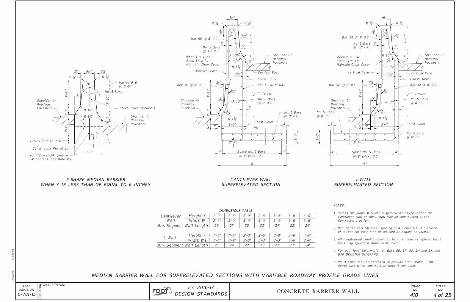
SUPERELEVATED SECTION
CANTILEVER WALL
WHEN Y IS LESS THAN OR EQUAL TO 6 INCHES
F-SHAPE MEDIAN BARRIER
SUPERELEVATED SECTION
L-WALL
TABLEDIMENSIONS
Wall
Cantilever YHeight 1'-0" 1'-6" 2'-0" 2'-6" 3'-0" 3'-6" 4'-0"
WWidth 2'-6" 2'-9" 3'-0" 3'-3" 3'-3" 3'-6" 3'-6"
Length Wall SegmentMin. 29' 27' 25' 23' 24' 22' 24'
YHeight 1'-0" 1'-6" 2'-0" 2'-6" 3'-0" 3'-6" 4'-0"
W1Width 2'-6" 2'-9" 3'-0" 3'-3" 3'-3" 3'-6" 3'-6"
Length Wall SegmentMin. 26' 24' 22' 21' 22' 21' 24'
L-Wall
MEDIAN BARRIER WALL FOR SUPERELEVATED SECTIONS WITH VARIABLE ROADWAY PROFILE GRADE LINES
@ 8" (Max.) O.C.
dowel bars when construction joint is not used.
5. No. 4 dowel may be extended to provide steel stake. Omit
BAR BENDING DIAGRAMS.
4. For additional information on Bars 5E, 5F, 5G, 5H and 5J, see
bars. Lap splices a minimum of 2'-0".
3. All longitudinal reinforcement to be continuous or spliced No. 5
of 4 feet for each side of all cold or expansion joints.
2. Reduce the vertical steel spacing to 4 inches O.C. a distance
Contractor's option.
Cantilever Wall or the L-Wall may be constructed at the
1. Unless the plans stipulate a specific wall type, either the
NOTES:
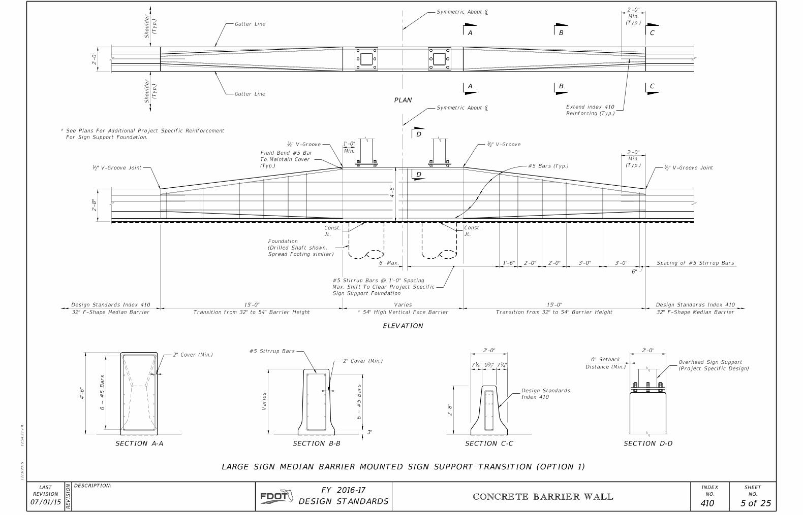
Gutter Line
Gutter Line
Symmetric About ¡
Reinforcing (Typ.)
Extend index 410
" V-Groove Joint21
" V-Groove43" V-Groove4
3
" V-Groove Joint21
Spread Footing similar)
(Drilled Shaft shown,
Foundation
2" Cover (Min.)#5 Stirrup Bars
2" Cover (Min.)
Index 410
Design Standards
(Project Specific Design)
Overhead Sign Support
Symmetric About ¡
Sign Support Foundation
Max. Shift To Clear Project Specific
#5 Stirrup Bars @ 1'-0" Spacing
(Typ.)
To Maintain Cover
Field Bend #5 Bar
Jt.
Const.
Jt.
Const.
12/3/2015
12:5
4:2
9 P
M
RE
VISIO
N
NO.
SHEET
NO.
INDEXDESCRIPTION:
REVISION
LAST
of DESIGN STANDARDS
FY 2016-17
CONCRETE BARRIER WALL
07/01/15 5 25 410
Distance (Min.)
Varie
s
3"
4'-
6"
* 54" High Vertical Face Barrier
For Sign Support Foundation.
* See Plans For Additional Project Specific Reinforcement
Spacing of #5 Stirrup Bars
Transition from 32" to 54" Barrier Height
6" Max.
2'-
8"
(Typ.)
Should
er
(Typ.)
Should
er
0" Setback
VariesDesign Standards Index 410
32" F-Shape Median Barrier
Design Standards Index 410
32" F-Shape Median Barrier
6"
15'-0"15'-0"
Transition from 32" to 54" Barrier Height
"417 "2
19 "417
2'-0" 2'-0"
3'-0"3'-0"2'-0"2'-0"1'-6"
4'-
6"
Min.
1'-0"
2'-
8"
2'-
0"
6 ~ #
5 Bars
#5 Bars (Typ.)
(Typ.)
Min.
2'-0"
(Typ.)
Min.
2'-0"
6 ~ #
5 Bars
A
A
C
C
B
B
D
D
SECTION B-B SECTION C-CSECTION A-A
ELEVATION
PLAN
SECTION D-D
LARGE SIGN MEDIAN BARRIER MOUNTED SIGN SUPPORT TRANSITION (OPTION 1)

2" Cover (Min.)#5 Stirrup Bars
2" Cover (Min.)
Index 410
Design Standards(Project Specific Design)
Overhead Sign Support
" V-Groove Joint21
" V-Groove43" V-Groove4
3
" V-Groove Joint21
Gutter Line
Gutter Line
Symmetric About ¡
Symmetric About ¡Reinforcing (Typ.)
Extend index 410
Drilled Shaft similar)
(Spread Footing shown,
Foundation
Sign Support Foundation
Max. Shift To Clear Project Specific
#5 Stirrup Bars @ 1'-0" Spacing
To Maintain Cover
Field Bend #5 Bar
Jt.
Const.
12/3/2015
12:5
4:2
9 P
M
RE
VISIO
N
NO.
SHEET
NO.
INDEXDESCRIPTION:
REVISION
LAST
of DESIGN STANDARDS
FY 2016-17
CONCRETE BARRIER WALL
07/01/15 6 25 410
Distance (Min.)
Varie
s
3"
Face Barrier
* 54" High Vertical
For Sign Support Foundation.
* See Plans For Additional Project Specific Reinforcement
Varies (15'-0" Min.) Varies (15'-0" Min.)
Varies
3'-0" Max.
Equal Spaces @
Spacing of #5 Stirrup Bars
* Transition from 32" to 54" Barrier Height* Transition from 32" to 54" Barrier Height
6" Max.
(Typ.)
Should
er
(Typ.)
Should
er
Varie
s
Reduced Shoulder
Reduced Shoulder
VariesDesign Standards Index 410
32" F-Shape Median Barrier
Design Standards Index 410
32" F-Shape Median Barrier
Varies
0" Setback
6"
4'-
6"
4'-
6"
2'-
8"
2'-
0"
Min.
1'-0"
2"-
8"
2'-0"2'-0"1'-6"
2'-0"
"417 "2
19 "417
#5 Bars (Typ.)
6 ~ #
5 Bars
(Typ.)
Min.
2'-0"
(Typ.)
Min.
2'-0"
6 ~ #
5 Bars
PLAN
ELEVATION
SECTION A-A
20
20
A B
A B C
C
SECTION C-C SECTION D-DSECTION B-B
D
D
20
1
20
1
LARGE SIGN MEDIAN BARRIER MOUNTED SIGN SUPPORT TRANSITION (OPTION 2)
1
1

Gutter Line
Gutter Line
Symmetric About ¡
Reinforcing (Typ.)
Extend index 410
" V-Groove Joint21
" V-Groove43" V-Groove4
3
Symmetric About ¡
" V-Groove Joint21
Drilled Shaft similar)
(Spread Footing shown,
Foundation
(Project Specific Design)
Overhead Sign Support
Index 410
Design Standards
2" Cover (Min.)
#5 Stirrup Bars2" Cover (Min.)
Sign Support Foundation
Max. Shift To Clear Project Specific
#5 Stirrup Bars @ 1'-0" Spacing
To Maintain Cover
Field Bend #5 Bar
Jt.
Const.
12/3/2015
12:5
4:3
0 P
M
RE
VISIO
N
NO.
SHEET
NO.
INDEXDESCRIPTION:
REVISION
LAST
of DESIGN STANDARDS
FY 2016-17
CONCRETE BARRIER WALL
07/01/15 7 25 410
Varies
Distance (Min.)
Varie
s
3"
Face Barrier
* 54" High Vertical
For Sign Support Foundation.
* See Plans For Additional Project Specific Reinforcement
Varies (15'-0" Min.) Varies (15'-0" Min.)
3'-0" Max.
Equal Spaces @
Varies6" Max. Spacing of #5 Stirrup Bars
* Transition from 32" to 54" Barrier Height* Transition from 32" to 54" Barrier Height
(Typ.)
Should
er
(Typ.)
Should
er
Varie
s
Design Standards Index 410
32" F-Shape Median Barrier
Design Standards Index 410
32" F-Shape Median Barrier
Varies
0" Setback
Reduced Shoulder
6"
4'-
6"
4'-
6"
2'-
0"
2'-
8"
Min.
1'-0"
2'-0"2'-0"1'-6"
2'-0"
"417 "2
19 "417
2'-
8"
#5 Bars (Typ.)
6 ~ #
5 Bars
(Typ.)
Min.
2'-0"
(Typ.)
Min.
2'-0"
6 ~ #
5 Bars
PLAN
SECTION C-C
20
SECTION D-DSECTION A-A SECTION B-B
A CB
D
D
1
20
A B C
ELEVATION
LARGE SIGN MEDIAN BARRIER MOUNTED SIGN SUPPORT TRANSITION (OPTION 3)
1

12/3/2015
12:5
4:3
0 P
M
RE
VISIO
N
NO.
SHEET
NO.
INDEXDESCRIPTION:
REVISION
LAST
of DESIGN STANDARDS
FY 2016-17
C
C
CONCRETE BARRIER WALL
07/01/14 8 25 410
Support Footing
Overhead Sign
Face
Safety Shape
Overhead Sign Support
Support Pedestal
Overhead Sign
End Reinforcement
Pedestal With Safety Shape Face
Overhead Sign Support
Support Pedestal
Overhead Sign
Conc. Fill Conc. Fill
Conc. FillConc. Fill
½" Expansion Material ½" Expansion Material
½" Expansion Material
½" Expansion Material
½" Expansion Joint
½" Expansion Material
Roadway Pavement
Shoulder Or
CONCRETE BARRIER WALL SPECIAL DETAILS, DETAIL B.
Doweled Transverse Construction Joint, See
20
1
20
1
Barrier Wall
Standard
1'-6" Min. 1'-6" Min.
1'-6" Min.
1'-6" Min.
Varies (See Plans)
Varies (See Plans)
SECTION CCELEVATION
PLAN
CONCRETE MEDIAN BARRIER WALL TRANSITIONS AT OVERHEAD SIGN SUPPORTS
2'-0"
20
1
20
1
Symmetrical About �
The Plans
Other Indexes Or As Called For In
1. Footing Extended As Called For On
NOTE:
Median Concrete Barrier Wall Overhead Sign Pedestal
12/3/2015
12:5
4:3
1 P
M
RE
VISIO
N
NO.
SHEET
NO.
INDEXDESCRIPTION:
REVISION
LAST
of DESIGN STANDARDS
FY 2016-17
CONCRETE BARRIER WALL
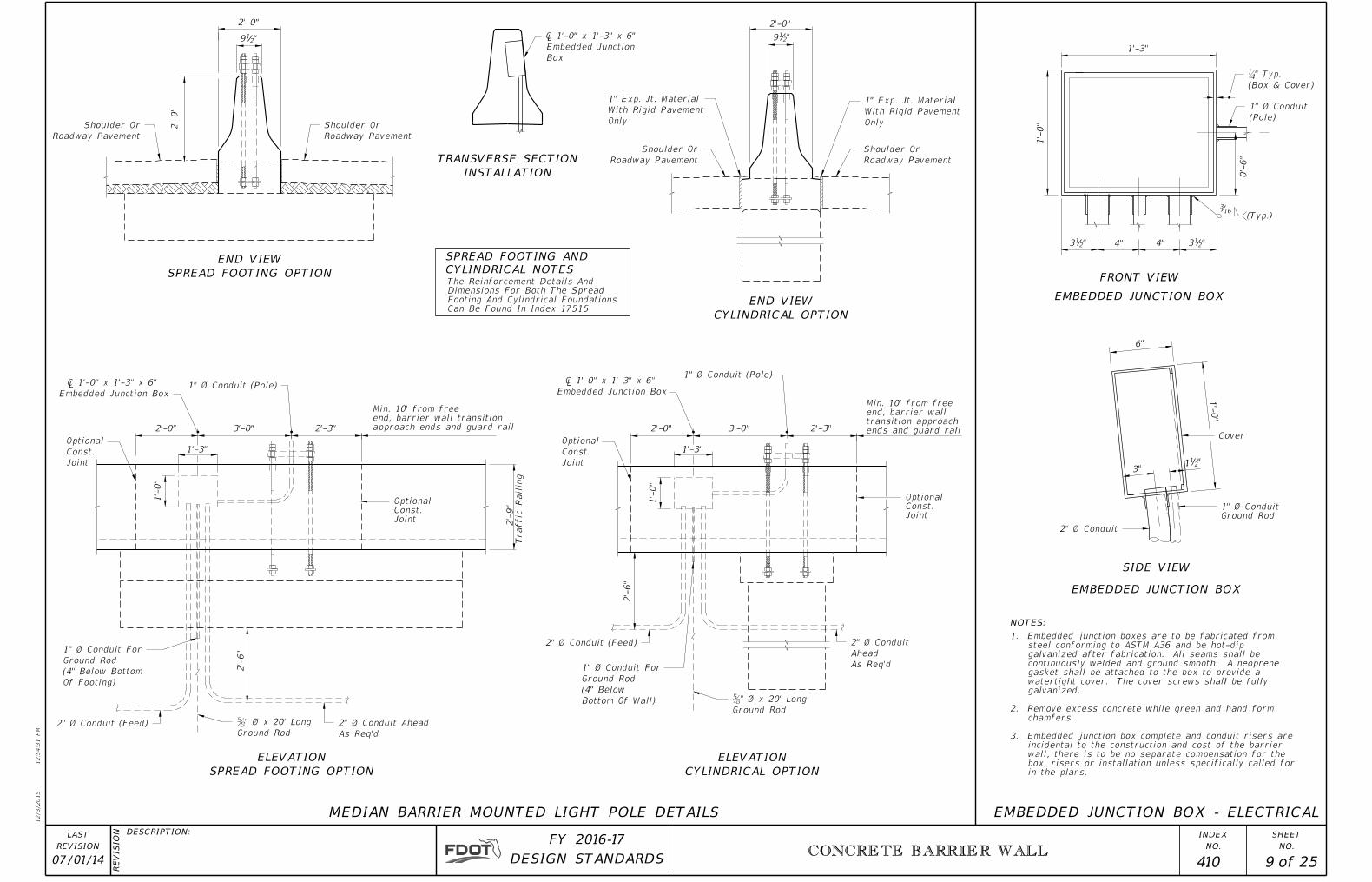
07/01/14 9 25 410
2" Ø Conduit (Feed)
Ground Rod
ƅ" Ø x 20' Long
2'-3"3'-0"2'-3"3'-0"
Joint
Const.
Optional
Joint
Const.
Optional
Roadway Pavement
Shoulder Or
Box
Embedded Junction
� 1'-0" x 1'-3" x 6"
Roadway Pavement
Shoulder Or
Only
With Rigid Pavement
1" Exp. Jt. Material
(Box & Cover)
¼" Typ.
(Pole)
1" Ø Conduit
1" Ø Conduit (Pole)
As Req'd
2" Ø Conduit Ahead
Ground Rod
ƅ" Ø x 20' Long
As Req'd
Ahead
2" Ø Conduit
1" Ø Conduit (Pole)
2" Ø Conduit (Feed)
2" Ø Conduit
Embedded Junction Box
� 1'-0" x 1'-3" x 6"Embedded Junction Box
� 1'-0" x 1'-3" x 6"
Roadway Pavement
Shoulder Or
Roadway Pavement
Shoulder Or
"21
13"
1'-
0"
6"
"2134"4""2
13
163
(Typ.)
0'-
6"
1'-3"
1'-
0"
"219
2'-0"
2'-0"
1'-3"
1'-
0"
2'-
6"
approach ends and guard rail
end, barrier wall transition
Min. 10' from free
2'-0"
1'-3"
1'-
0"
2'-
6"
Traffic Railin
g
2'-
9"
2'-
9"
2'-0"
"219
CYLINDRICAL NOTES
SPREAD FOOTING AND
FRONT VIEW
SIDE VIEW
Cover
EMBEDDED JUNCTION BOX
EMBEDDED JUNCTION BOX - ELECTRICAL
EMBEDDED JUNCTION BOX
in the plans.
box, risers or installation unless specifically called for
wall; there is to be no separate compensation for the
incidental to the construction and cost of the barrier
3. Embedded junction box complete and conduit risers are
chamfers.
2. Remove excess concrete while green and hand form
galvanized.
watertight cover. The cover screws shall be fully
gasket shall be attached to the box to provide a
continuously welded and ground smooth. A neoprene
galvanized after fabrication. All seams shall be
steel conforming to ASTM A36 and be hot-dip
1. Embedded junction boxes are to be fabricated from
Only
With Rigid Pavement
1" Exp. Jt. Material
Joint
Const.
Optional
Of Footing)
(4" Below Bottom
Ground Rod
1" Ø Conduit For
Joint
Const.
Optional
Bottom Of Wall)
(4" Below
Ground Rod
1" Ø Conduit For
Ground Rod
1" Ø Conduit
SPREAD FOOTING OPTION
END VIEW
INSTALLATION
TRANSVERSE SECTION
CYLINDRICAL OPTION
END VIEW
ends and guard rail
transition approach
end, barrier wall
Min. 10' from free
SPREAD FOOTING OPTION
ELEVATION
CYLINDRICAL OPTION
ELEVATION
NOTES:
Can Be Found In Index 17515.
Footing And Cylindrical Foundations
Dimensions For Both The Spread
The Reinforcement Details And
MEDIAN BARRIER MOUNTED LIGHT POLE DETAILS

12/3/2015
12:5
4:3
3 P
M
RE
VISIO
N
NO.
SHEET
NO.
INDEXDESCRIPTION:
REVISION
LAST
of DESIGN STANDARDS
FY 2016-17
Transition Section
Transition Section
Transition Section
Assembly (Flared)
Approach End Anchorage
Assembly (Flared), See Note 1
Approach End Anchorage
Wall Terminal Configuration
Transition To Suit Barrier
15' Shoulder Gutter
Assembly (Flared), See Note 1
Approach End Anchorage
CONCRETE BARRIER WALL
07/01/14 10 25 410
See Note 3
See Note 3
See Note 3
See Note 4
See Note 4
See Note 4
1 : 50
Varies (See Plans)
Slab
Approach
Varies
Grassed
Varies (See Plans)
Varies
Shoulder Pavement
Varies (See Plans)
Bridge
Shoulder Pavement
Varies (See Plans)
Grassed
Guardrail (For Additional Details See Index No. 400)
Guardrail (For Additional Details See Index No. 400)
Bridge Traffic Rail
Bridge Traffic Rail
Bridge Traffic Rail
Expanded Shoulder
Shoulder Line
For Extended Guardrail
Normal Shoulder
Varies (Deflected Barrier Wall )
2 Panels
2 Panels
4'
Requirements See Plans
For Shoulder Gutter
Notation Left
See Shoulder
Slab
Approach
Slab
Approach
WITH GRASSED OR PAVED SHOULDERS AND GUARDRAIL
WITH SHOULDER GUTTER AND GUARDRAIL
WITH CONCRETE BARRIER WALL (SHOULDER)
Shoulder Wall Constructed
Expanded Shoulder When
Shoulder Wall
Shoulder Wall
Shoulder Wall Constructed
Expanded Shoulder When
Shoulder Wall
Shoulder Wall Constructed
Expanded Shoulder When
Shoulder Line
Shoulder Pavement
Shoulder Wall
Bridge
Bridge
For Variations In Shoulder Widths
Deflected Shoulder Gutter When Required
NOTES:
1.
400. No. Index II, Type Anchorage End by anchored be shallguardrail
tangent The facilities. 2-way 2-lane for except ends trailing on deleted beTo
2. facilities. 2-way 2-lane for except ends trailing on deleted beTo
3.
walls. retaining on or slab approach with constructed rails trafficconcrete
to connected guardrail when measurement end for J Detail 400, No. Index Seewalls.
barrier shoulder to connected guardrail when payment guardrail for measurementEnd
shown. not guardrail under paving asphaltMiscellaneous
treatments. end trailing for notes flagged other See 400. No. Index indetailed
as rails, traffic bridge for as same the guardrail by or cushions, crash by shieldedbe
shall ends wall the need, of length approach the satisfies alone barriers rigidthese
of either When Wall. Shoulder or railings traffic concrete with walls retainingeither
of length the exceeds need of length when barriers roadside approach showViews
CONCRETE BARRIER WALLS ON BRIDGE APPROACHES
EITHER REINFORCED CONCRETE BARRIER WALL (SHOULDER) OR RETAINING WALL WITH CONCRETE TRAFFIC RAILING
For Additional Details See Index No. 400
Call For Attenuator In Lieu Of Guardrail, See Note 2
" Min. Approach Guardrail Except When Plans 2184'-4
" Guardrail21For 84'-4
Expanded Shoulder
Bridge Shoulder
Bridge Shoulder
Bridge Shoulder
Paved Shoulder
Paved Shoulder
4.
5.
Bridge Shoulder)
(Width Same As
Roadway Shoulder
Bridge Shoulder)
(Width Same As
Roadway Shoulder
Bridge Shoulder)
(Width Same As
Roadway Shoulder
accordance with the Design Standards, Index 400 Series and the plans.
Guardrail connection to concrete traffic railings or retaining walls shall be in

12/3/2015
12:5
4:3
4 P
M
RE
VISIO
N
NO.
SHEET
NO.
INDEXDESCRIPTION:
REVISION
LAST
of DESIGN STANDARDS
FY 2016-17
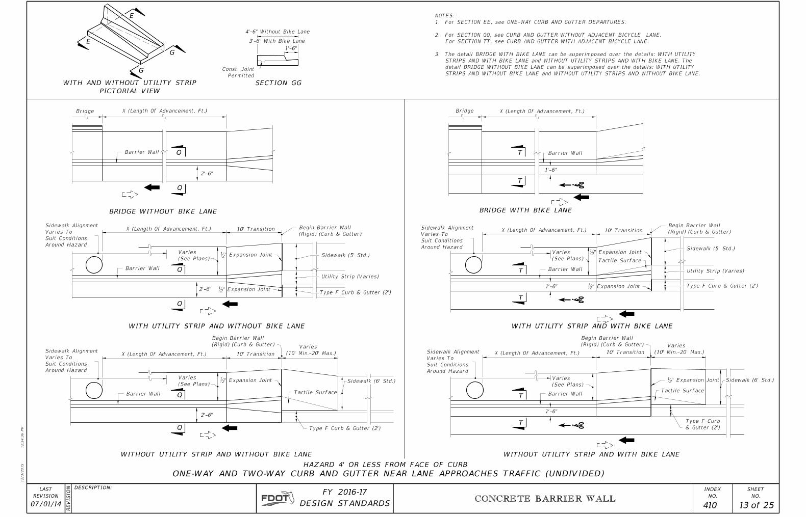
ONE-WAY CURB AND GUTTER DEPARTURES
2'-6"
Around Hazard
Suit Conditions
Varies To
Sidewalk Alignment
Around Hazard
Suit Conditions
Varies To
Sidewalk Alignment
Around Hazard
Suit Conditions
Varies To
Sidewalk Alignment
Around Hazard
Suit Conditions
Varies To
Sidewalk Alignment
CONCRETE BARRIER WALL
07/01/14 11 25 410
(See Plans)
Varies
Barrier Wall
Barrier Wall
Barrier Wall Barrier Wall
Barrier Wall
Barrier Wall
(Rigid) (Curb & Gutter)
End Barrier Wall
Sidewalk (5' Std.)
Utility Strip (Varies)
Tactile Surface
(Rigid) (Curb & Gutter)
End Barrier Wall
Sidewalk (5' Std.)
Utility Strip (Varies)
Sidewalk (6' Std.)
(Rigid) (Curb & Gutter)
End Barrier Wall
& Gutter (2')
Type F Curb
(Rigid) (Curb & Gutter)
End Barrier Wall
Tactile Surface
Permitted
Const. Joint
& Gutter (2')
Type F Curb
Sidewalk (6' Std.)
& Gutter (2')
Type F Curb
& Gutter (2')
Type F Curb
ƀ" Expansion Joint
ƀ" Expansion Joint
ƀ" Expansion Jointƀ" Expansion Joint
ƀ" Expansion Joint
ƀ" Expansion Joint
2'-
8"
10ƀ"
1'-6"
See Note 2
See Note 1
(See Plans)
Varies
(See Plans)
Varies
(See Plans)
Varies
Permitted
Const. Joint
10' Transition
1'-6"
HAZARD 4' OR LESS FROM FACE OF CURB
1'-6"
10' Transition
Q
Q
10' Transition
2'-6"
Q
Q
2'-6"
Otherwise Called For In Plans
Departure- 25' Unless
10' Transition
SECTION DD
2'-1¾"
Otherwise Called For In Plans
Departure- 25' Unless
Otherwise Called For In Plans
Departure- 25' Unless
Otherwise Called For In Plans
Departure- 25' Unless
1'-6"
Otherwise Called For In Plans
Departure- 25' Unless
Otherwise Called For In Plans
Departure- 25' Unless
Q
Q
E
E
D
D
BRIDGE WITH BIKE LANE
WITH UTILITY STRIP AND WITH BIKE LANE WITH UTILITY STRIP AND WITHOUT BIKE LANE
WITHOUT UTILITY STRIPS AND WITHOUT BIKE LANE
BRIDGE WITHOUT BIKE LANE
WITHOUT UTILITY STRIP AND WITH BIKE LANE
SECTION EE
3Ɔ"
12"
2'-9" With Bike Lane
1'-6" With Bike Lane
2'-6" Without Bike Lane
3'-9" Without Bike Lane
PICTORIAL VIEW
WITH AND WITHOUT UTILITY STRIP
T
T
T
T
T
T
ADJACENT BICYCLE LANE.
4. For SECTION QQ, see CURB AND GUTTER WITHOUT ADJACENT BICYCLE LANE. For SECTION TT, see CURB AND GUTTER WITH
WITHOUT BIKE LANE and WITHOUT UTILITY STRIPS AND WITHOUT BIKE LANE.
STRIPS AND WITH BIKE LANE. The detail BRIDGE WITHOUT BIKE LANE can be superimposed over the details: WITH UTILITY STRIPS AND
3. The detail BRIDGE WITH BIKE LANE can be superimposed over the details: WITH UTILITY STRIPS AND WITH BIKE LANE and WITHOUT UTILITY
located 12" from the barrier wall. Dowels may be placed within or adjacent to the keyway.
Manner: Five No. 5 bars 15" long shall be embedded 7" into the footing. The dowels shall be spaced 15" on centers with the first dowel
2. When Construction Joints Are Utilized For Transition Segment Construction The Stem Shall Be Doweled To The Footing In The Following
Asphalt-saturated roofing felt with the ends crimped.
Specification Section 416. The ends of the dowels extending into the transition segment shall be wrapped with one layer of 15 lb. Type I
centers shall be drilled in the end of the barrier and No. 6 bars 15" long set in an Adhesive Bonded Material System per Standard
1. Transition Segments Shall Be Doweled Into The End Of The Barrier Wall In The Following Manner: Four 1" diameter holes 6" deep on 6"
NOTES:
Bridge Approach Slab Bridge Approach Slab

12/3/2015
12:5
4:3
5 P
M
RE
VISIO
N
NO.
SHEET
NO.
INDEXDESCRIPTION:
REVISION
LAST
of DESIGN STANDARDS
FY 2016-17
(0.02 Std.)
0.02-0.04
TWO-WAY CURB AND GUTTER TRAFFIC DEPARTURE
CONCRETE BARRIER WALL
07/01/14 12 25 410
Sidewalk (5' Std.)
& Gutter (2')
Type F Curb
Utility Strip (Varies)
Barrier Wall
Tactile Surface
Barrier Wall
Sidewalk (5' Std.)
Utility Strip (Varies)
Barrier Wall
(6' Std.)
Sidewalk
Barrier Wall
Tactile Surface
Permitted
Const. Joint
Barrier Wall Barrier Wall
& Gutter (2')
Type F Curb
ƀ" Expansion Joint
ƀ" Expansion Joint
ƀ" Expansion Joint
ƀ" Expansion Joint
ƀ" Expansion Joint
ƀ" Expansion Joint
& Gutter (2')
Type F Curb
Tactile Surface
(Rigid) (Curb & Gutter)
End Barrier Wall
(6' Std.)
Sidewalk
(Rigid) (Curb & Gutter)
End Barrier Wall
(Rigid) (Curb & Gutter)
End Barrier Wall
(Rigid) (Curb & Gutter)
End Barrier Wall
& Gutter (2')
Type F Curb
10' Transition X (Length Of Advancement, Ft.)
HAZARD 4' OR LESS FROM FACE OF CURB
Varies
(10' Min.-20' Max.)
10' Transition X (Length Of Advancement, Ft.)
1'-6"
T
T
1'-6"
T
T
10' Transition X (Length Of Advancement, Ft.)
2'-6"
10' Transition X (Length Of Advancement, Ft.)
(10' Min.-20' Max.)
Varies
2'-6"
E
E
1'-6"
BridgeX (Length Of Advancement, Ft.)
2'-6"1'-6"
T
T
X (Length Of Advancement, Ft.) Bridge
Q
Q
Q
Q
Q
Q
F
F
3'-6" With Bike Lane
4'-6" Without Bike Lane
Around Hazard
Conditions
Varies To Suit
Sidewalk Alignment
Around Hazard
Conditions
Varies To Suit
Sidewalk Alignment
Around Hazard
Conditions
Varies To Suit
Sidewalk Alignment
Around Hazard
Conditions
Varies To Suit
Sidewalk Alignment
BRIDGE WITHOUT BIKE LANE
WITH UTILITY STRIP AND WITHOUT BIKE LANE
WITHOUT UTILITY STRIP AND WITHOUT BIKE LANE WITHOUT UTILITY STRIP AND WITH BIKE LANE
WITH UTILITY STRIP AND WITH BIKE LANE
BRIDGE WITH BIKE LANE
SECTION FF
PICTORIAL VIEW
WITH AND WITHOUT UTILITY STRIP
For Section TT, see CURB AND GUTTER WITH ADJACENT BICYCLE LANE.
5. For SECTION QQ, see CURB AND GUTTER WITHOUT ADJACENT BICYCLE LANE.
4. For SECTION EE, see ONE-WAY CURB AND GUTTER DEPARTURES.
STRIPS AND WITHOUT BIKE LANE and WITHOUT UTILITY STRIPS AND WITHOUT BIKE LANE.
UTILITY STRIPS AND WITH BIKE LANE. The detail BRIDGE WITHOUT BIKE LANE can be superimposed over the details: WITH UTILITY
3. The detail BRIDGE WITH BIKE LANE can be superimposed over the details: WITH UTILITY STRIPS AND WITH BIKE LANE and WITHOUT
SHOULDER BARRIER WALL WHEN OFFSET FROM ABOVE GROUND HAZARD < 1'-6" AND THE DESIGN SPEED ≤ 45 MPH.
the wall may be accommodated by the details on HAZARD PENETRATION INTO STEM OF RIGID CONCRETE BARRIER WALLS; AND
2. The 1'-6" and 2'-6" offsets to toe of barrier wall cannot be reduced to accommodate hazards; however, hazards located in the stem of
BICYCLE LANE.
1. For X=Length of advancement in feet for near and opposing lanes and for sectional details see CURB AND GUTTER WITHOUT ADJACENT
NOTES:
12/3/2015
12:5
4:3
6 P
M
RE
VISIO
N
NO.
SHEET
NO.
INDEXDESCRIPTION:
REVISION
LAST
of DESIGN STANDARDS
FY 2016-17
ONE-WAY AND TWO-WAY CURB AND GUTTER NEAR LANE APPROACHES TRAFFIC (UNDIVIDED)
Tactile Surface
CONCRETE BARRIER WALL
07/01/14 13 25 410
Tactile Surface
Type F Curb & Gutter (2')
Tactile Surface
Type F Curb & Gutter (2')
Utility Strip (Varies)
Sidewalk (5' Std.)
(Rigid) (Curb & Gutter)
Begin Barrier Wall
Sidewalk (5' Std.)
Utility Strip (Varies)
(See Plans)
Varies Sidewalk (6' Std.)
& Gutter (2')
Type F Curb
Permitted
Const. Joint
(Rigid) (Curb & Gutter)
Begin Barrier Wall
Type F Curb & Gutter (2')
Barrier Wall
Barrier Wall
Barrier Wall
(See Plans)
Varies
(See Plans)
Varies
(See Plans)
Varies
ƀ" Expansion Joint
ƀ" Expansion Joint
ƀ" Expansion Joint
ƀ" Expansion Joint
ƀ" Expansion Joint
ƀ" Expansion Joint
(Rigid) (Curb & Gutter)
Begin Barrier Wall
Barrier Wall
Barrier Wall
Barrier Wall
Sidewalk (6' Std.)
(Rigid) (Curb & Gutter)
Begin Barrier Wall
HAZARD 4' OR LESS FROM FACE OF CURB
Q
Q
10' TransitionX (Length Of Advancement, Ft.)
2'-6"
10' Transition10' TransitionX (Length Of Advancement, Ft.)
2'-6"
Q
Q
T
1'-6"
T
1'-6"
10' TransitionX (Length Of Advancement, Ft.)
T
T
(10' Min.-20' Max.)
Varies
SECTION GG
1'-6"
X (Length Of Advancement, Ft.)
2'-6"
Q
Q
Bridge X (Length Of Advancement, Ft.)Bridge
1'-6"
T
T
X (Length Of Advancement, Ft.)
E
E
4'-6" Without Bike Lane
3'-6" With Bike Lane
BRIDGE WITH BIKE LANE
WITH UTILITY STRIP AND WITH BIKE LANE
WITHOUT UTILITY STRIP AND WITH BIKE LANEWITHOUT UTILITY STRIP AND WITHOUT BIKE LANE
WITH UTILITY STRIP AND WITHOUT BIKE LANE
BRIDGE WITHOUT BIKE LANE
PICTORIAL VIEW
WITH AND WITHOUT UTILITY STRIP
Around Hazard
Suit Conditions
Varies To
Sidewalk Alignment
Around Hazard
Suit Conditions
Varies To
Sidewalk Alignment
Around Hazard
Suit Conditions
Varies To
Sidewalk Alignment
Around Hazard
Suit Conditions
Varies To
Sidewalk Alignment
G
G
(10' Min.-20' Max.)
Varies
STRIPS AND WITHOUT BIKE LANE and WITHOUT UTILITY STRIPS AND WITHOUT BIKE LANE.
detail BRIDGE WITHOUT BIKE LANE can be superimposed over the details: WITH UTILITY
STRIPS AND WITH BIKE LANE and WITHOUT UTILITY STRIPS AND WITH BIKE LANE. The
3. The detail BRIDGE WITH BIKE LANE can be superimposed over the details: WITH UTILITY
For SECTION TT, see CURB AND GUTTER WITH ADJACENT BICYCLE LANE.
2. For SECTION QQ, see CURB AND GUTTER WITHOUT ADJACENT BICYCLE LANE.
1. For SECTION EE, see ONE-WAY CURB AND GUTTER DEPARTURES.
NOTES:
(Rigid) (Curb & Gutter)
Begin Concrete Barrier Wall
That Requires Shielding
Or Other Hazard
End Of Bridge Rail
That Requires Shielding
End Of Bridge Rail Or Other Hazard12/3/2015
12:5
4:3
6 P
M
RE
VISIO
N
NO.
SHEET
NO.
INDEXDESCRIPTION:
REVISION
LAST
of DESIGN STANDARDS
FY 2016-17
CONCRETE BARRIER WALL
07/01/15 14 25 410
2"
2"
R 1¾"
R 1¾"
2"
2'-
8"
2'-
8"
3"
3"
3"
3"
5"
5"
2¼"
2¼"
2ƀ"
1ƀ"
2ƀ"
Varies
3" Min.
3" Min.
1'-3"
2"
3"
3"
R ¾"
R ¾"
No. 5 Bars @ 8" O.C.
No. 5 Bars @ 8" O.C.
R ¾"
R 10"
R ¾"
R 10"
7¾"
7¾"
No. 5 Bars @ 8" O.C.
Pavt. Slope
Match Adjacent
Adjacent Pavt. Slope
Field Bend to Match
No. 5 Bars @ 8" O.C.
4'-0"
4'-0"
Bar 5K @ 8" O.C.
Bar 5K @ 8" O.C.
1'-3"2'-6"
1'-
10"
7"
1'-
0"
"2
14
1'-
10"
7"
"2
14
1'-
0"
2'-6"
1'-
0"
"4
17
"4
37
See Insert A
See Insert A
"4
17
@ 8" O.C.
No. 5 Bars
@ 8" O.C.
No. 5 Bars
A
B
Index 410 Index 420
or 425
4"
(Typ.)
4"
(Typ.)
Barrier Wall
Face Of
Wall Need
Beginning Of Barrier
Departure
Point Of
2"
2"
X (Length Of Advancement, Ft.)
Offset Control Point
d
Departure Line
Type 'F' Curb & Gutter
X (Length Of Advancement, Ft.)(Rigid) (Curb & Gutter)
End Concrete Barrier Wall
Offset Control Point
Continuous
Point Of Departure
Departure Line
d
D
Barrier Wall
Face Of
RIGHT SIDE APPROACH SHOWN - LEFT SIDE OPPOSITE HAND
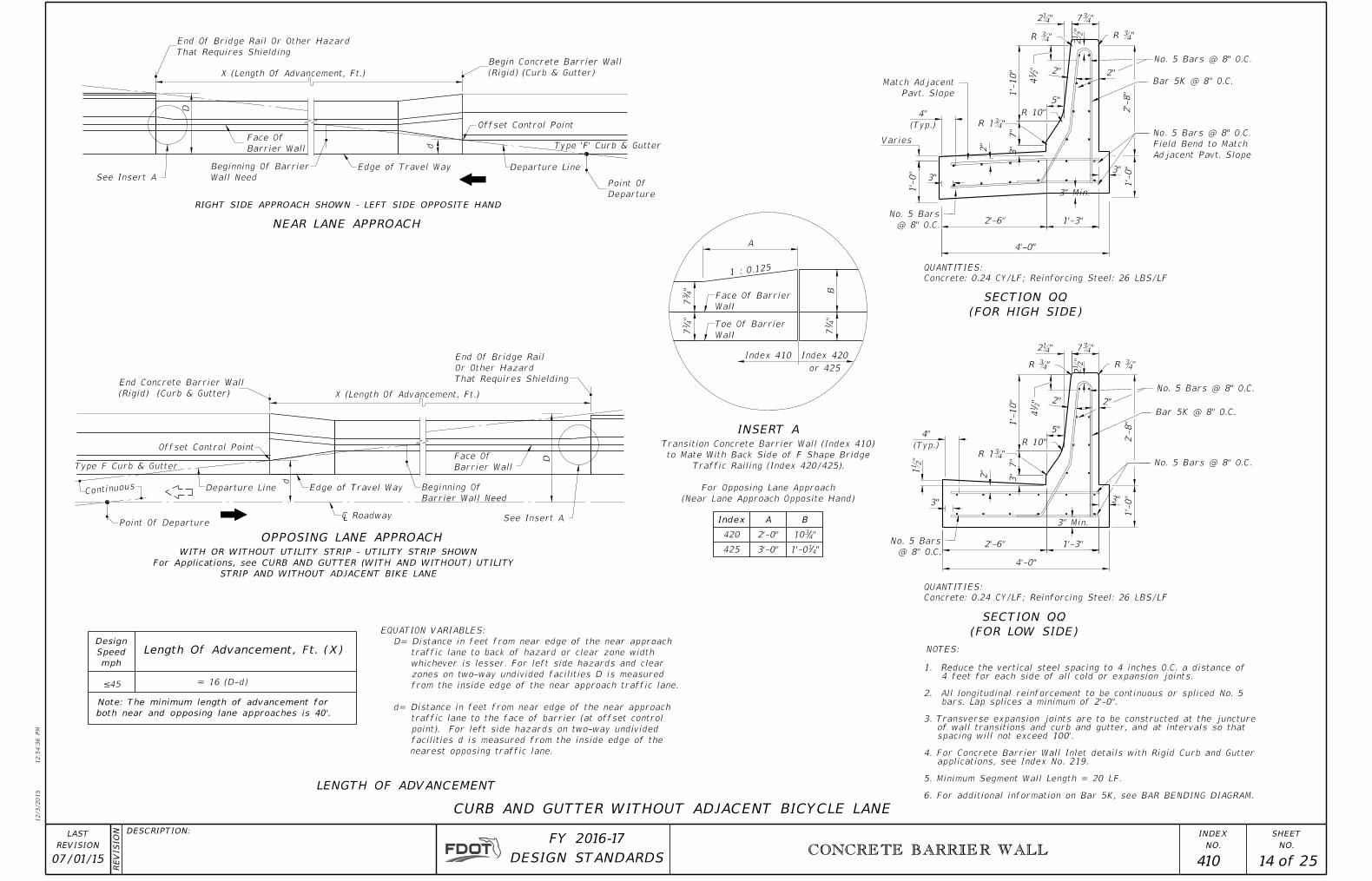
CURB AND GUTTER WITHOUT ADJACENT BICYCLE LANE
16 (D-d)≤45
both near and opposing lane approaches is 40'.
Note: The minimum length of advancement for
Length Of Advancement, Ft. (X)
mph
Speed
Design
LENGTH OF ADVANCEMENT
(FOR HIGH SIDE)
SECTION QQ
(FOR LOW SIDE)
SECTION QQ
Barrier Wall Need
Beginning Of
Type F Curb & Gutter
STRIP AND WITHOUT ADJACENT BIKE LANE
For Applications, see CURB AND GUTTER (WITH AND WITHOUT) UTILITY
WITH OR WITHOUT UTILITY STRIP - UTILITY STRIP SHOWN
D
=
Concrete: 0.24 CY/LF; Reinforcing Steel: 26 LBS/LF
QUANTITIES:
Concrete: 0.24 CY/LF; Reinforcing Steel: 26 LBS/LF
QUANTITIES:
NEAR LANE APPROACH
OPPOSING LANE APPROACH
NOTES:
nearest opposing traffic lane.
facilities d is measured from the inside edge of the
point). For left side hazards on two-way undivided
traffic lane to the face of barrier (at offset control
d= Distance in feet from near edge of the near approach
from the inside edge of the near approach traffic lane.
zones on two-way undivided facilities D is measured
whichever is lesser. For left side hazards and clear
traffic lane to back of hazard or clear zone width
D= Distance in feet from near edge of the near approach
EQUATION VARIABLES:
INSERT A
1 : 0.125
420
Index A
425
2'-0"
3'-0"
B
"4310
"411'-0
Wall
Face Of Barrier
Wall
Toe Of Barrier
(Near Lane Approach Opposite Hand)
For Opposing Lane Approach
Traffic Railing (Index 420/425).
to Mate With Back Side of F Shape Bridge
Transition Concrete Barrier Wall (Index 410)
Edge of Travel Way
Edge of Travel Way
¡ Roadway
6. For additional information on Bar 5K, see BAR BENDING DIAGRAM.
5. Minimum Segment Wall Length = 20 LF.
applications, see Index No. 219.4. For Concrete Barrier Wall Inlet details with Rigid Curb and Gutter
spacing will not exceed 100'. of wall transitions and curb and gutter, and at intervals so that 3. Transverse expansion joints are to be constructed at the juncture
bars. Lap splices a minimum of 2'-0".2. All longitudinal reinforcement to be continuous or spliced No. 5
4 feet for each side of all cold or expansion joints.1. Reduce the vertical steel spacing to 4 inches O.C. a distance of

(Rigid) (Curb & Gutter)
Begin Concrete Barrier Wall
Shielding
That Requires
Or Other Hazard
End Of Bridge Rail
That Requires Shielding
Or Other Hazard
End Of Bridge Rail
12/3/2015
12:5
4:3
7 P
M
RE
VISIO
N
NO.
SHEET
NO.
INDEXDESCRIPTION:
REVISION
LAST
of DESIGN STANDARDS
FY 2016-17
CONCRETE BARRIER WALL
07/01/15 15 25 410
2'-
8"
3"
2"
2"
W2
5"
5"
2"
3"3"
W2
2¼"
No. 5 Bars @ 8" O.C.
2ƀ"
1ƀ"
No. 5 Bars @ 8" O.C.
1'-
0"
2¼"
2ƀ"
Sidewalk
3" Min
2"
3"
3" Min
1'-
0"
2'-
8"
Varies
Bar 5K @ 8" O.C.
Varies
R ¾"
No. 5 Bars @ 8" O.C.
R ¾"
R Ƃ"R Ƃ"
R 10"
R 1¾"
7¾"
7¾"
1'-3"
1'-3"
1'-6"
1'-6"
Adjacent Pavt. Slope
Field Bend to Match
No. 5 Bars @ 8" O.C.
Bar 5K @ 8" O.C.
No. 5 Bars @ 8" O.C.
No. 5 Bars @ 8" O.C.
R 10"
Pavement Slope
Match Adjacent
Varie
s
3"
R 1¾"
1'-
10"
7"
"4
14
1'-
0"
1'-
0"
3"
7"
1'-
0" "4
14
Min.
7"
Min.
7"
Face Of Barrier Wall
d Departure Line
Point Of Departure
D
Face Of Barrier Wall
D
d
Tactile Surface
Type F Curb & Gutter
Tactile Surface
Type F Curb & Gutter
X (Length Of Advancement, Ft.)
X (Length Of Advancement, Ft.)(Rigid) (Curb & Gutter)
End Concrete Barrier Wall
Line
Departure
2"
2"
2"
Gutter Line
Gutter Line
NEAR LANE APPROACH
OPPOSING LANE APPROACH
CURB AND GUTTER WITH ADJACENT BICYCLE LANE
Point Of Departure
SECTION HH
6"
H
BARRIER WALL (RIGID) (CURB & GUTTER)
SIDEWALK DRAINAGE SLOT FOR
H
of Need And Offset Control Point
Beginning Of Barrier Wall, Length Edge Of Travelway
Edge Of Travelway
of Need And Offset Control Point
Beginning Of Barrier Wall, Length
PICTORIAL VIEW
(FOR LOW SIDE)
SECTION TT
(FOR HIGH SIDE)
SECTION TT
2"
NOTES:
RIGHT SIDE APPROACH SHOWN - LEFT SIDE OPPOSITE HAND
STRIP AND ADJACENT BIKE LANE FOR APPLICATIONS
For Applications, see CURB AND GUTTER (WITH AND WITHOUT UTILITY
WITH OR WITHOUT UTILITY STRIP - UTILITY STRIP SHOWN
Continuous
Continuous
QUANTITIES
(LF)Wall
Barrier
Of
Length
W2CY/LF
Concrete
LBS/LF
Steel
Reinforcing
30'≥ 3'-3" 0.21 24
29' to26' 3'-6" 0.22 24
¡ Roadway
(See Note #7)
Drainage Slot
18" x 2ƀ"
provide 2" concrete cover.
Drainage slots, vertical and horizontal bars shall be placed to
in front and back lines of vertical reinforcement. On each side of
shall be located such that only two bars are cut away or deleted
intervals not exceeding 50' in fill sections and 20' cut sections. Slots
and unless otherwise shown in the plans, slots shall be spaced at
7. Drainage slots shall be located at all low points along the sidewalk
6. For additional information on Bar 5K, see BAR BENDING DIAGRAM.
5. Minimum Segment Wall Length = 20 LF.
applications, see Index No. 219.
4. For Concrete Barrier Wall Inlet details with Rigid Curb and Gutter
spacing will not exceed 100'.
of wall transitions and curb and gutter, and at intervals so that
3. Transverse expansion joints are to be constructed at the juncture
bars. Lap splices a minimum of 2'-0".
2. All longitudinal reinforcement to be continuous or spliced No. 5
4 feet for each side of all cold or expansion joints.
1. Reduce the vertical steel spacing to 4 inches O.C. a distance of

12/3/2015
12:5
4:3
8 P
M
RE
VISIO
N
NO.
SHEET
NO.
INDEXDESCRIPTION:
REVISION
LAST
of DESIGN STANDARDS
FY 2016-17
Terminal Connector
Thrie-Beam
CONCRETE BARRIER WALL
CONCRETE BARRIER WALL
07/01/14 16 25 410
GUARDRAIL CONNECTION TO CONCRETE BARRIER WALL APPROACH ENDS
Terminal Connector
Thrie-Beam
Terminal Connector
Thrie-Beam
Terminal Connector
Thrie-Beam
6'-3" 6'-3"
Direction Of Lap
Direction Of Lap
Direction Of Lap
Single Faced Guardrail
Single Faced Guardrail
Single Faced Guardrail
End Measurement For Guardrail Payment
Direction Of Lap
Direction Of Lap
Double Faced Guardrail
MEDIAN BARRIER WALL
RIGHT SIDE APPROACH ONE-WAY LANES OR RIGHT SIDE APPROACH TWO-LANE TWO-WAY
LEFT SIDE APPROACH ONE-WAY LANES
LEFT SIDE OF TWO-LANE TWO-WAY (APPROACH FOR FAR LANE)
(1)(2)(3)(4)(5)(6)(7)(8)
6 @ 1'-6¾"3 @ 3'-1ƀ"
7¼"I
I J
J
K
K
L
L
K
K
L
L
K
K
L
L
Shoulder Wall
Shoulder Wall
Shoulder Wall
Transition Section, see TRANSITION SECTION NOTES
SECTION NOTES
See TRANSITION
Transition Panel
6'-3" W-Thrie Beam
washers under heads and nuts.
long HS hex bolts and nuts with Ɔ" plain round
thrie-beam terminal connector plate and 5-Ɔ"x12"
Attach to shoulder barrier wall with a 21"x12"xƅ"
Ɔ" plain round washers under heads and nuts.
wall with 5-Ɔ"x15" long HS hex bolts and nuts with
2. Attach thrie-beam terminal connector to median barrier
SHOULDER BARRIER.
STANDARD GUARDRAIL APPROACH TO
Guardrail and Offset Block Views, see
1. For Section II, JJ, KK and LL
NOTES:
12'-6" W-Beam Panel
12'-6" W-Beam Panel (Nested)
12'-6" W-Beam Panel (Nested)
12'-6" W-Beam Panel (Nested)
Barrier Wall Payment
End Measurement For Concrete
12'-6" Thrie-Beam Panel 25' Thrie-Beam Panel
For Traffic Approach To Barrier Wall
12'-6" Thrie-Beam (Nested)

12/3/2015
12:5
4:3
9 P
M
RE
VISIO
N
NO.
SHEET
NO.
INDEXDESCRIPTION:
REVISION
LAST
of DESIGN STANDARDS
FY 2016-17
Terminal Connector
Thrie-Beam
Timber Offset Timber Offset
(2 Reqd.)
With Washer & Beam Washer
With Beam Washer And Nut
22" Long For Steel Post,
24" Long For Timber Post,
ƅ" Ø Button Head Bolt,
(2 Reqd.)
With Washer & Beam Washer
With Beam Washer And Nut
22" Long For Steel Post,
24" Long For Timber Post,
ƅ" Ø Button Head Bolt,
Transition Panel
6'-3" W-Thrie Beam
CONCRETE BARRIER WALL
07/01/14 17 25 410
Thrie-Beam
¾" Ø Holes
Timber Offset Timber Offset
Thrie-Beam
Reinforcement
Free End
With ¾" Ø Holes
Back-Up Plate
12"x12"x¼"
Nut & Washer (2 Reqd.)
Bolt With Beam Washer And
ƅ" Ø 16" Button Head
With ¾" Ø Holes
Back-Up Plate
12"x12"x¼"
Nut & Washer (2 Reqd.)
Bolt With Beam Washer And
ƅ" Øx17" Button Head
1'-
9"
1'-
9"
4"
12'-6" Thrie-Beam Panel
25' Thrie-Beam Panel
Direction Of Lap
Varies, See Index No. 400, Detail K
6ƀ" 5ƃ"
4ƀ" 3ƃ"
2ƅ"
5¾"
3¾"
3¼"
4Ƅ"
2Ƅ"
GUARDRAIL CONNECTION TO CONCRETE BARRIER WALL APPROACH ENDS
SECTION II SECTION JJ
SECTION LLSECTION KK
JJIIJJ & LLII & KK
1Ɔ"
STANDARD GUARDRAIL APPROACH TO SHOULDER BARRIER
1'-
9"
1'-
9"
(1)(2)(3)(4)(5)(6)(7)(8)
FOR USE AT SECTIONS II, JJ, KK & LL
STANDARD TIMBER OR PLASTIC OFFSET BLOCKS FIELD TRIMMED
See Note 8See Note 8
See Note 8
¾" Ø Holes ¾" Ø Holes
¾" Ø Holes
1'-
7¾"
1'-
10"
1'-
7¾"
1'-
10"
1'-
10"
1'-
7¾"
1'-
10"
1'-
7¾"See Note 8
Shoulder Wall
USING EITHER TIMBER OR STEEL POSTS
POSTS AND FOR SINGLE FACED GUARDRAIL
FOR DOUBLE FACED GUARDRAIL USING TIMBER
USING STEEL POSTS
FOR DOUBLE FACED GUARDRAIL
Reinforcement
Free End
NOTES: SECTIONTRANSITION
1.
walls. barrier concrete shoulder toapply
also wall barrier concrete median for shown limits payment and dimensions longitudinalThe
2.
3.
Specifications. Standard the of 562 Section withaccordance
in metalized be shall surfaces reamed the beams, nested fit to necessary is reamingWhere
4. shown. posts timber used, be may post guardrail timber or steelEither
5. (5). and (3) (1), numbers posts at posts and blocks to bolted be not shall beams nestedThe
6.
7. 400. No. Index to refer information guardrail additionalFor
8.
wall.barrier
of ends approach on Thrie-Beams Nested wall; barrier of ends trailing on Thrie-BeamSingle
guardrail connections for one-way lanes, see FREE END REINFORCEMENT.
W-beam elements do not apply to these transition schemes. For barrier wall trailing end numbers (1), (2), (3), (5), (6), and (8).
On the trailing side of MEDIAN BARRIER WALL, offset blocks may be omitted at posts
12'-6" W-Beam Panel12'-6" W-Beam Panel (Nested
)
12'-6" Thrie-Beam Panel (Nested)

12/3/2015
12:5
4:4
0 P
M
RE
VISIO
N
NO.
SHEET
NO.
INDEXDESCRIPTION:
REVISION
LAST
of DESIGN STANDARDS
FY 2016-17
(FIELD TRIMMED)
STANDARD THRIE-BEAM OFFSET BLOCK
CONCRETE BARRIER WALL
07/01/14 18 25 410
<3'
<3'
R 125'
R 125'
21'
25'
Round Pier Shown
Round Pier Shown
Thrie-beam Panel (Nested)
1: 15
1: 10
4 0.064.00
8 7.99 0.26
12 11.98 0.58
16
20
21
24
25
Y
X
15.96
19.91
20.91
23.85
24.83
1.02
1.60
1.76
2.30
2.49
R 125'
11'-9"
7'-7"
5" Nom.
Stacked Back O
f RailBeam Washers
End Measurement Fo
r Concrete B
arrier Wall Pay
ment
End Measur
ement For Co
ncrete Bar
rier Wall Pa
yment
GUARDRAIL TRANSITIONS
1: 10 OR 1: 15
FOR USE WITH EITHER
Nom.
7ƀ"
5ƀ" Nom.
"Y" (FT)
OFFSETSDISTANCE
"X" (FT)LENGTH (FT)
ARC
PLAN FOR DESIGN SPEED ≤ 45 MPH
PLAN FOR DESIGN SPEED ≥ 50 MPH
≤ 4 feet.
in chords having lengths
Wall may be constructed
Note:
See Note 5
See Note 6
See Note 6
See Note 6
See Note 6
See Note 5
Field Trimmed, See Detail, Right
Standard Thrie-Beam Offset Block,
Stacked Back O
f RailBeam Washers
x
X
Field Trimmed, See Detail, Right
Standard Thrie-Beam Offset Block,
1'-
7¾"
1'-
10"
Terminal Connector
Thrie-Beam
Terminal Connector
Thrie-Beam
Thrie-beam Panel
(Nested)
End Measurement For Guardrail P
ayment
End Measurement For Guardrail Payment
SHOULDER BARRIER WALL AT ABOVE GROUND RIGID HAZARDS WHEN OFFSET FROM HAZARD < 3'
Are Applicable.
ENDS For Post Spacing And Bolt Connections, Steel Or Timber Posts
9. See GUARDRAIL CONNECTION TO CONCRETE BARRIER WALL APPROACH
HAZARD < 1'-6" AND THE DESIGN SPEED ≥ 50 MPH.
SHOULDER BARRIER WALL WHEN OFFSET FROM ABOVE GROUND
8. For additional information on PLAN FOR DESIGN SPEED ≥ 50 MPH, see
1'-6" AND THE DESIGN SPEED ≤ 45 MPH.
SHOULDER BARRIER WHEN OFFSET FROM ABOVE GROUND HAZARD <
7. For additional information on PLAN FOR DESIGN SPEED ≤ 45 MPH, see
OF RIGID CONCRETE BARRIER WALLS.
6. For details at Rigid Hazard, see HAZARD PENETRATION INTO STEM
14" or 18" long) and nuts with ƅ" plain round washers under nuts.
5. 12"x12"x¼" galvanized steel back-up plate with ƅ" post bolts (either
hex bolts and nuts with Ɔ" plain round washers under heads and nuts.
21"x12"xƅ" thrie beam terminal connector plate and 5-Ɔ"x12" long HS
4. Attach thrie-beam terminal connector to shoulder barrier wall with a
3. Refer to Index No. 400 for additional guardrail information.
APPROACH ENDS.
connections, see GUARDRAIL CONNECTION TO CONCRETE BARRIER WALL
For walls with normal offsets from hazards and their guardrail
to concrete barrier wall trailing ends may be used.
one-way facilities, the end connection on W-Beam guardrail connection
way facilities. For Details on trailing ends of two-way multilane and
approaches and to the approaching and trailing ends of two-lane two-
guardrail connections shown on this sheet apply to one-way
and trailing ends of both one-way and two-way facilities. The
2. The barrier wall radial segments are intended for use on approach
as detailed in the plans.
occupy the same location, the wall and structure are to be modified
where the barrier wall and slope pavement or other structure would
CONCRETE SHOULDER WALL, Section QQ, or Section TT. In cases
be constructed in accordance with the detail for REINFORCED
1. The affected segments between bent supports or pier columns shall
NOTES:
Transition Secti
on, See Note 9
Transition Section, See
Note 9

12/3/2015
12:5
4:4
0 P
M
RE
VISIO
N
NO.
SHEET
NO.
INDEXDESCRIPTION:
REVISION
LAST
of DESIGN STANDARDS
FY 2016-17
CONCRETE BARRIER WALL
07/01/14 19 25 410
Top Of Barrier
Top Of Barrier
Top Of Barrier
M
N
N
M
M
M
N
N
O
O
O
O
2¼"
2¼"
2¼"
2¼"
2¼"
2¼"
Heel Of Footing
Heel Of Footing
Heel Of Footing Heel Of Footing
Heel Of Footing
Heel Of Footing
Back Of Barrier
Back Of Barrier
Top Of Barrier
Top Of Barrier
Top Of Barrier
Face Of Barrier
Gutter Line
ƀ" V-Groove
ƀ" V-Groove
ƀ" V-Groove ƀ" V-Groove
ƀ" V-Groove
ƀ" V-Groove
ƀ" Expansion Material
Gutter Line
Face Of Barrier
ƀ" Expansion Material
Gutter Line
Face Of Barrier
Back Of Barrier
Expansion Material
Existing Pier With ƀ"
Wall Up Against The
The Back Face Of Barrier
Contractor's Option: Cast
ƀ" Min. Open Joint Or
Expansion Material
Existing Pier With ƀ"
Wall Up Against The
The Back Face Of Barrier
Contractor's Option: Cast
ƀ" Min. Open Joint Or
Gutter Line
Face Of Barrier
Back Of Barrier
Back Of Barrier
Face Of Barrier
Gutter Line
ƀ" V-Groove
Back Of Barrier
Face Of Barrier
Gutter Line
ƀ" V-Groove
ƀ" Expansion Material
ƀ" Expansion Material
5"
5"
5"
5"
5"
5"
"4
37
"4
37
"4
37
"4
37
"4
37
"4
37
b. 4' downstream of pier edge for an inclining approach.
a. 4' upstream of pier edge for a declining approach.
provided at one of the following locations:
5. When thru drainage is required, a 3"x 12" Drain Slot shall be
Bridge bent supports and piers are shown.
clearances between above ground hazards and the walls.
concrete barrier walls, where site conditions impose reduced
4. The details on this sheet are treatments to the F-shape
< 1'-6" AND THE DESIGN SPEED ≥ 50 MPH.
BARRIER WALL WHEN OFFSET FROM ABOVE GROUND HAZARD
3. For High Speed SECTIONS MM and NN, see SHOULDER
< 1'-6" AND THE DESIGN SPEED ≤ 45 MPH.
BARRIER WALL WHEN OFFSET FROM ABOVE GROUND HAZARD
2. For Low Speed SECTIONS MM, NN and OO, see SHOULDER
other associated wall treatments.
static force. See the plans for limits of wall sections and
provide lateral support to resist the LRFD lateral equivalent
1. These treatments are not applicable to hazards that cannot
NOTES:
Pier
Offset
Offset
Pier
Pier
Offset
Pier
Offset
Pier
Offset
Pier
Offset
RIGID HAZARD PENETRATION INTO STEM OF CONCRETE BARRIER WALL
PIER AT BACK OF CONCRETE BARRIER WALL
PIER PENETRATION INTO TOP OF CONCRETE BARRIER WALL
PIER AT FACE OF CONCRETE BARRIER WALL

12/3/2015
12:5
4:4
1 P
M
RE
VISIO
N
NO.
SHEET
NO.
INDEXDESCRIPTION:
REVISION
LAST
of DESIGN STANDARDS
FY 2016-17
CONCRETE BARRIER WALL
07/01/15 20 25 410
1'-
10"
3"
1-9"
3"
1-9"
3"
ƀ"
2ƀ"
2ƀ"
1-9"
2ƀ"
5"
"432
Ea. Side of Pier �
W/ 6" Overlap 4'
W4.0 / 4.0 WWM
Galvanized 6x6
32" SHOULDER WALL
5"
2¼"
1'-0"
2¼" 2¼"
5"
3"
3"
3"
R ¾" R ¾"
R 10"R 10"R 10"
1'-
0"
1'-0"
1'-
0"
7¾"
Pier Pier
Permitted
Construction Joint
4' Ea. Side of Pier �
No. 5 Bars @ 4" O.C.
Pier
Material
ƀ" Expansion
Pavement
Shoulder
Pavement
Shoulder
Gutter LineGutter Line Gutter Line
Varies (5" Min.)
Bar 5A @ 8" O.C. 4' Ea. Side of Pier �
Bar 5L @ 4" O.C. for
1'-
10"
Material
ƀ" Expansion
Material
ƀ" Expansion
Permitted
Construction Joint
Permitted
Construction Joint
@ 8" O.C.
No. 5 Bars
32" SHOULDER WALL
R ¾" R ¾"R ¾"
R 1Ƃ"Pavement
Shoulder
@ 8" O.C.
No. 5 Bars
1'-0"
@ 8" O.C.
No. 5 Bars
R 1Ƃ" R 1Ƃ"
@ 8" O.C.
No. 5 Bars
@ 8" O.C.
No. 5 Bars
@ 8" O.C.
No. 5 Bars
@ 8" O.C.
No. 5 Bars
@ 8" O.C.
No. 5 Bars
"2
14
2" 2"7"
"2
14
2"
7"
1'-
10"
"411'-8
7"
6"
2'-3"
5"
1'-
0"
2'-0¼"
5" 5"
32" OR 42" SHOULDER WALL
Maintain 3" Cover
As Necessary To
Bend Bar 5L
Field Cut And
Pier
OffsetOffset
Pier
Offset
Pier
3"
3"
3"
3" 3" 3"
3"
4"
SHOULDER BARRIER WALL WHEN OFFSET FROM ABOVE GROUND HAZARD < 1'-6" AND THE DESIGN SPEED ≤ 45 MPH
WHEN PIER OFFSET ≥ 15½"
SECTION MM
WHEN 12Ƃ" ≤ PIER OFFSET < 15½"
SECTION NN
WHEN 8Ƃ" ≤ PIER OFFSET < 12Ƃ"
SECTION OO
3" Min.3" Min. 3" Min.
wall may be cast against Pier with ƀ" Expansion Material.
4. ƀ" Min. Expansion Joint or at the contractor's option: Back face of barrier
3. For additional information on Bars 5A and 5L, see BAR BENDING DIAGRAMS.
splices a minimum of 2'-0".
2. All longitudinal reinforcement to be continuous or spliced No. 5 bars. Lap
for each side of all cold or expansion joints.
1. Reduce the vertical steel spacing to 4 inches O.C. a distance of 4 feet
NOTES:

12/3/2015
12:5
4:4
2 P
M
RE
VISIO
N
NO.
SHEET
NO.
INDEXDESCRIPTION:
REVISION
LAST
of DESIGN STANDARDS
FY 2016-17
CONCRETE BARRIER WALL
07/01/15 21 25 410
R 10"
R 1¾"
R 10"
R 1¾"
2"
3"
3"
3"
1'-
9"
5" 3" 5"1'-
9"
3"
2"
2ƀ"
2¼"1'-
10"
2ƀ"
2¼"
3'-3"
2ƀ"
5"
3"
3"3"
1'-3"
4"
2ƀ"
3"
3"
1'-
9"
3"
3"
2"
1'-3"
4"
42" SHOULDER WALL 42" SHOULDER WALL 42" SHOULDER WALL (TYPICAL)
2"
2"
1'-0"
3"
3"
R ¾"
Pier Pier
1'-
0"
1'-0"
Gutter LineGutter Line
R ¾"R ¾" R ¾"
R 1¾"
R 10"
R ¾" R ¾"
Gutter Line
Bar 5M @ 8" O.C.Bar 5N @ 8" O.C.
Bar 5A @ 8" O.C. 4' Ea. Side of Pier ¡
Bar 5P @ 4" O.C. for
Bar 5A @ 8" O.C.
Bar 5M @ 8" O.C.
Material
ƀ" Expansion
Permitted
Construction Joint
Bar 5M @ 8" O.C.
1'-
0"
2¼"
Bar 5N @ 8" O.C.
Bar 5N @ 8" O.C.
Bar 5B @ 8" O.C.
Permitted
Construction Joint
Permitted
Construction Joint
Permitted
Construction Joint
2'-0¼" 2'-3"
@ 8" O.C.
No. 5 Bars
@ 8" O.C.
No. 5 Bars
1'-0"
@ 8" O.C.
No. 5 Bars
@ 8" O.C.
No. 5 Bars
@ 8" O.C.
No. 5 Bars
@ 8" O.C.
No. 5 Bars
Gutter Line
@ 8" O.C.
No. 5 Bars
@ 8" O.C.
No. 5 Bars
@ 8" O.C.
No. 5 Bars
@ 8" O.C.
No. 5 Bars
See Note 6
1'-
0"
@ 8" O.C.
No. 5 Bars
@ 8" O.C.
No. 5 Bars
"2
14
2"
5"
7"
3"
1'-
10"
"2
14
7"
5"
3"
3"
2"
"2
14
2"
1'-
10"
7"
3"
"2
14
2"
3"
Pavement
Shoulder
Pavement
Shoulder
Pavement
Shoulder
Joint Details
No. 218 For
See Index
1'-
0"
10"
10"
42" SHOULDER WALL (MODIFIED)
2"
10"
2'-3"
"437 "4
37
2"
Varies (5" Min.)
Material
ƀ" Expansion
Inlet
Barrier Wall
Pier Offset Pier Offset
SHOULDER BARRIER WALL WHEN OFFSET FROM ABOVE GROUND HAZARD < 1'-6" AND DESIGN SPEED ≥ 50 MPH
1'-
9"
Reinforcing Steel 43 LBS/LF
Concrete 0.35 CY/LF
QUANTITIES:
Reinforcing Steel 39 LBS/LF
Concrete 0.31 CY/LF
QUANTITIES:
WHEN 12¾" ≤ PIER OFFSET < 16¾"
SECTION NN
WHEN PIER OFFSET ≥ 16¾"
SECTION MM
3" Min.3" Min. 3" Min. 3" Min.
over 15'-0"
42" height
Transition to
6. ƀ" Min. Expansion Joint or at the contractor's option: Back face of barrier wall may be cast against Pier with ƀ" Expansion Material.
5. Where the 42" SHOULDER WALL does not abut the pier, use the TYPICAL or MODIFIED sections.
4. For Section OO, see SHOULDER BARRIER WALL WHEN OFFSET FROM ABOVE GROUND HAZARD < 1'-6" AND THE DESIGN SPEED ≤ 45 MPH.
3. For additional information on Bars 5A, 5B, 5M, 5N and 5P, see BAR BENDING DIAGRAMS.
2. All longitudinal reinforcement to be continuous or spliced No. 5 bars. Lap splices a minimum of 2'-0".
1. Reduce the vertical steel spacing to 4 inches O.C. a distance of 4 feet each side of all cold joints.
NOTES:

12/3/2015
12:5
4:4
3 P
M
RE
VISIO
N
NO.
SHEET
NO.
INDEXDESCRIPTION:
REVISION
LAST
of DESIGN STANDARDS
FY 2016-17
CONCRETE BARRIER WALL
07/01/15 22 25 410
d
D
D (R
A)
(LA)
d D (L
A)
(RA)
d
Back of Pier or Bent
General Note No. 21)
required (see Index 400,
Type 3 Object Marker when
Gutter Line
Edge of Traffic Lane
Beginning Length Of Need
Beginning Length Of Need (RA)
Back of Pier or Bent
Gutter Line
Edge of Traffic Lane
Beginning Length Of Need (LA)
Shoulder Wall
Shoulder WallShoulder Wall
Departure (RA)
Point of
¡ Roadway
Departure (LA)
Point of
Departure (RA)
Point of
TWO-LANE TWO-WAY TRAFFIC
Pier or Bent
RIGHT APPROACH (RA)
LEFT APPROACH (LA)
SHOULDER BARRIER WALL WHEN OFFSET FROM ABOVE GROUND HAZARD < 1'-6" AND DESIGN SPEED ≥ 50 MPH
(LEFT SIDE OPPOSITE HAND)
ONE-WAY TRAFFIC
100'-0"
100'-0"
Pier or Bent
100'-0"
Shoulder WallShoulder Wall
Shoulder Wall
VerticalTransition Transition
Vertical
TransitionVertical
15'-0"
42" Barrier
15'-0" 15'-0"
42" Barrier
12/3/2015
12:5
4:4
3 P
M
RE
VISIO
N
NO.
SHEET
NO.
INDEXDESCRIPTION:
REVISION
LAST
of DESIGN STANDARDS
FY 2016-17 CONCRETE BARRIER WALL
CONCRETE BARRIER WALL
07/01/14 23 25 410
32"
Heig
ht
412"
42" Shoulder Wall (Typ.)
No. 5 Bars @ 8" O.C.
Vertical
Transition
Wall (Typ.)
32" Shoulder
Barrier Wall Continuation)
Bolts (Omit With Concrete
� Thrie-Beam Guardrail
Cut Splice & Lap
Bars 5M & 5N Field
Construction Joint Permitted
3ƀ"
Barrier Wall Continuation)
Bolts (Omit With Concrete
� Thrie-Beam Guardrail
1'-1ƀ"
@ 8" O.C.
Bar 5A
Construction Joint Permitted
Shoulder Pavement
Wall End Transition
Reinforcment 3' Into 42" Shoulder
& Supporting Footing Horizontal
Extend 32" Shoulder Wall (Typ.)
42"
Heig
ht
15'-0"
Barrier Wall Continuation)
Bolts (Omit With Concrete
� Thrie-Beam Guardrail
Transition
Tapered
End or Begin
(See Plan View)
Tapered Transition
End or Begin
"412 "8
73
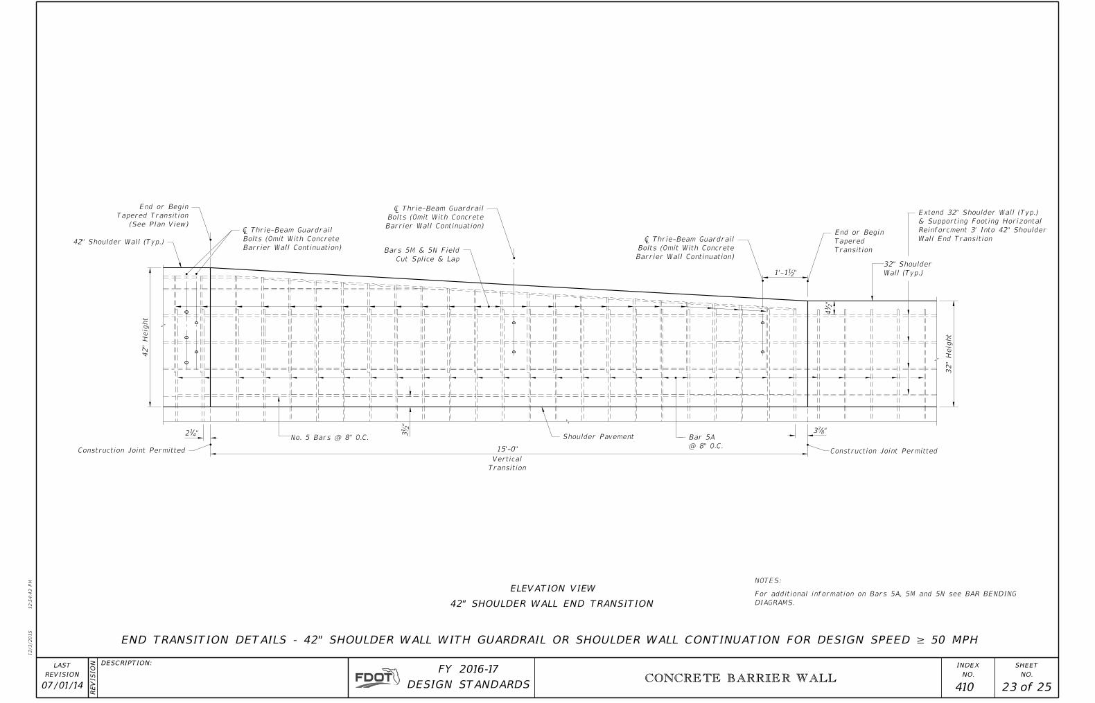
END TRANSITION DETAILS - 42" SHOULDER WALL WITH GUARDRAIL OR SHOULDER WALL CONTINUATION FOR DESIGN SPEED ≥ 50 MPH
ELEVATION VIEW
42" SHOULDER WALL END TRANSITION
NOTES:
DIAGRAMS.
For additional information on Bars 5A, 5M and 5N see BAR BENDING
A
A
B
B
12/3/2015
12:5
4:4
4 P
M
RE
VISIO
N
NO.
SHEET
NO.
INDEXDESCRIPTION:
REVISION
LAST
of DESIGN STANDARDS
FY 2016-17
CONCRETE BARRIER WALL
07/01/15 24 25 410
7¾"
2"
2"
6'-
6"
1'-
9"
3"
3"
7"
3"
3"
1'-
0"
2'-3"
2¼"
2ƀ"
3"
1'-
9"
2¼"
"2
12
3" Min.3" Min.
"2
12
15'-0"
Horizontal Transition
Vertical
Transition
Vertical
Transition
15'-0"
Horizontal Transition
Material
ƀ" Expansion
R 10"
R 1¾"
R ¾"R ¾"
Wall
42" Median
42" Half Wall
Varies M
2"2"
2"2"
3'-
0"
Wall
Standard Barrier
42"
Heig
ht
32"
Heig
ht
Gutter Line
Below
Half Wall
See 42"
In Wall Cavity
Granular Fill
Pavement
Roadway
Shoulder Or
Below
Half Wall
See 42"
Material
ƀ" Expansion
Permitted
Joint
Construction
R 1¾"
R 10"
16" O.C.
Bars 5R @
27ƀ" Max.)
Varies (9ƀ" Min.
About �
Symmetrical Material
ƀ" Expansion
Over Granular Fill
4" Concrete Cap
85'-0"
Over Granular Fill
4" Concrete Cap
@ 8" O.C.
No. 5 Bars
@ 8" O.C.
No. 5 Bars3" 3"
@ 8" O.C.
No. 5 Bars
@ 16" O.C.
No. 5 Bars
Cap
4" Concrete
Cap
4" Concrete
@ 8" O.C.
No. 5 Bars
Gutter Line
Pavement
Shoulder
Pavement
Shoulder
Pavement
Roadway
Shoulder Or
R ¾"R ¾"
2"
@ 8" O.C.
Bar 5A
@ 8" O.C.
Bar 5N
@ 16" O.C.
No. 5 Bars
Permitted
Joint
Construction
5"
1'-
10"
7"
3"
"2
14
1'-
10"
5"
15'-0"
15'-0"
10"
10"
8" O.C.
Bar 5M @
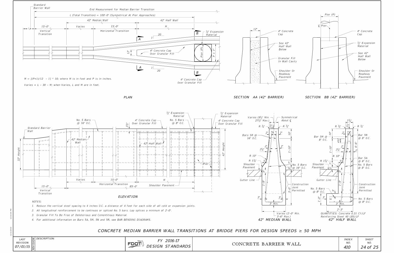
L (Total Transition) = 100'-0" (Symmetrical At Pier Approaches)
42" Half Wall
Varies
20
1
M
Over Granular Fill
4" Concrete Cap
12"
P + 1"
Pier (P)
Barrier Wall
Standard
12"
Pier (P)
Pier
� Pier
ELEVATION
PLAN
CONCRETE MEDIAN BARRIER WALL TRANSITIONS AT BRIDGE PIERS FOR DESIGN SPEEDS ≥ 50 MPH
1
20
42" Median Wall
Material
ƀ" Expansion
Over Granular Fill
4" Concrete Cap
Reinforcing Steel 40 LBS/LF
QUANTITIES: Concrete 0.31 CY/LF
SECTION AA (42" BARRIER) SECTION BB (42" BARRIER)
Shoulder Pavement
3'-6" Max.)
Varies (2'-0" Min.
42" MEDIAN WALL 42" HALF WALL
End Measurement for Median Barrier Transition
Varies = L - 30 - M; when Varies, L and M are in feet.
M = [(P+1)/12 - 1] * 10; where M is in feet and P is in inches.
4. For additional information on Bars 5A, 5M, 5N and 5R, see BAR BENDING DIAGRAMS.
3. Granular Fill To Be Free of Deleterious and Cementitious Material.
2. All longitudinal reinforcement to be continuos or spliced No. 5 bars. Lap splices a minimum of 2'-0".
1. Reduce the vertical steel spacing to 4 inches O.C. a distance of 4 feet for each side of all cold or expansion joints.
NOTES:
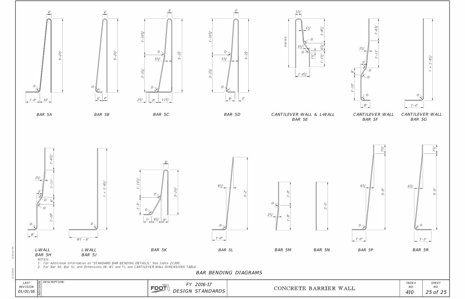
12/3/2015
12:5
4:4
5 P
M
RE
VISIO
N
NO.
SHEET
NO.
INDEXDESCRIPTION:
REVISION
LAST
of DESIGN STANDARDS
FY 2016-17
CONCRETE BARRIER WALL
01/01/16 25 25 410
6"
6"
"2
11
4"
Varie
s
"212
3"
1½"
1'-
8½"
6¾"
2¼"
2¼"
1'-
10"
W1 - 6"
Y + 1'-
9½"
Y + 1'-
9½"
2¾"
6¾"
4"
1'-
10
¾"
1'-
10
¾"
3'-
3¾"
5½"
1'-
10"
5"
1'-
11"
1'-
11"
5"
6¾"
1'-3"
1'-
9"
6"
4" 4"4"
"2111
4""4
15
8"
1'-0"
5'-
5"
5'-
5"
"2
15'-
2
10"1'-0"
"2
15'-
2
8"
5¾" 5¾"
8"
"2
11'-
1
1'-0¼"
1'-4"
5'-
2"
6½"
1'-0"
"2
13'-
2
6"
1'-
11
½"
1'-
3"
"4187"
8"
1'-
0"
2'-
5"
"2
17
"2
17
"21
5'-
2
"21
5'-
2
3'-
3¾"
BAR 5B BAR 5DBAR 5CBAR 5A
BAR 5H
L-WALL
D
D
D
D
D
D
D
D
D
D
D
D
D
DDD
D
D D
D
D
BAR 5G
CANTILEVER WALL
BAR 5F
CANTILEVER WALL
BAR BENDING DIAGRAMS
BAR 5M BAR 5N
D
BAR 5PBAR 5L
BAR 5J
L-WALL
BAR 5E
CANTILEVER WALL & L-WALL
BAR 5R
1'-
6¾"
1'-
6¾"
BAR 5K
2. For Bar 5G, Bar 5J, and Dimensions (W, W1 and Y), see CANTILEVER WALL DIMENSIONS TABLE.
1. For Additional Information on "STANDARD BAR BENDING DETAILS," See Index 21300.
NOTES: