g 100 ie-xie confort & g 100 ie-xie/gta confort · conteúdo de água da caldeira peso aprox....
TRANSCRIPT

G 100 IE-XIE Confort &G 100 IE-XIE/GTA Confort
Calderas de gasInstrucciones de Instalación,Montaje y Funcionamientopara el INSTALADOR Página .................... 11
EGasheizkesselInstallations-, Montage-und Betriebsanleitungfür den INSTALLATEUR Seite ........................ 17
D
Gas BoilersInstallation, Assembly andOperating Instructionsfor the INSTALLER Page ....................... 13
Caldaie a gasIstruzioni d’Installazione,Montaggio e Funzionamentoper l’INSTALLATORE Pagina..................... 20
I
Chaudières à gazInstructions d’Installation,de Montage et de Fonctionnement,pour l´INSTALLATEUR Page ....................... 15
FCaldeiras a gásInstruções de Instalação,Montagem e Funcionamentopara o INSTALADOR Página ..................... 22
P
GB

2
1 2 Válvula de seguridadSafety valveSoupape de sécurité
Embudo descargaDischarge funnelEntonnoir de déchargeEntlastungstrichterImbuto di scaricoFunil descarga
Conducir la tubería al desagüeRoute pipe to drainConduire à la tuyauterie de sortie d’eauRohrleitung bis zur AbflußleitungPortare la tubazione allo scaricoCanalizar para o esgoto
Gas / Gas / Gaz / Gas / Gas / Gás
Retorno / ReturnRetour / RückslaufRitorno / Retorno
Ida / Flow / DépartVorlauf / Mandata / Ida
11
2 3
20
1
19
18
4 3
5 6
7 10
9
12
17
12
17
SicherheitsventilValvola di sicurezzaVálvula de segurança
5
8
7
20
6
4
1918
11

3
7 8
9 12
13
14
15
16
1313
14
15
1621
21
25
24
23
26
22

4
10
G 100
Termostato de seguridadLimit thermostatThermostat de sécuritéSicherheitsthermostatTermostato di sicurezzaTermostato de segurança
230 V
Válvula de gas / Gas valveVanne de gaz / GasventilValvola del gas / Válvula de gás
Circulador Calefacción / CH pumpCirculateur chauffage
Umwälzpumpe HeizungPompa di circolazione del riscaldamento
Circulador do Aquecimento Central
Transductor presiónPressure transducerTransducteur de pressionDrucksensorTrasduttore di pressioneTransdutor de pressão
Sonda de CalderaBoiler sensorSonde BallonKesselfühlerSonda della caldaiaSonda da caldeira
Termostato reflujo humosFlue spillage limit thermostatThermostat reflux fuméesThermostat Rückströmung AbgasThermostat riflusso fumiTermostato de anti-retorno dos fumos

5
11
G 100 / GTA
230 V
Circulador A.C.S. / DHW pumpCirculateur d’E.C.S.Umwälzpumpe TrinkwarmwasserPompa di circolazione dell’A.C.S.Circulador de A.Q.S.
Sonda DepósitoCylinder sensorSonde BallonSpeicherfühlerSonda del SerbatoioSonda do depósito
Válvula de gas / Gas valveVanne de gaz / GasventilValvola del gas / Válvula de gás
Termostato de seguridadLimit thermostatThermostat de sécuritéSicherheitsthermostatTermostato di sicurezzaTermostato de segurança
Circulador Calefacción / CH pumpCirculateur chauffage
Umwälzpumpe HeizungPompa di circolazione del riscaldamento
Circulador do Aquecimento Central
Transductor presiónPressure transducerTransducteur de pressionDrucksensorTrasduttore di pressioneTransdutor de pressão
Sonda de CalderaBoiler sensorSonde BallonKesselfühlerSonda della caldaiaSonda da caldeira
Termostato reflujo humosFlue spillage limit thermostatThermostat reflux fuméesThermostat Rückströmung AbgasThermostat riflusso fumiTermostato de anti-retorno dos fumos

6
Características principales / Main features / Principales caractéristiquesHauptmerkmale / Caratteristiche principali / Características principais
elamkreMehcsirtkelE/seuqirtceléseuqitsirétcaraC/atadlacirtcelE/sacirtcélesacitsíretcaraCsacirtcélesacitsíretcaraC/ehcirtteleehcitsirettaraC
zH05~V032/022
lanimonlitúaicnetoPtuptuOlanimoN
elituelanimonecnassiuPgnutsielztuN-nneN
elanimonelituaznetoPlanimonlitúaicnêtoP
litúotneimidneRycneiciffEteNelitutnemedneR
dargsgnuztuNelituaseR
litúotnemidneR
sotnemeleed.ºNsnoitcesfo.oN
.erbN stneméléredlhaznAetnemelezieHitnemeleidºN
sotnemeleed.ºN
serodameuqedºN.oN srenrubfo
sruelûrbed.erbNrennerBredlhaznA
irotaicurbidºNserodamieuqedº.N
h/lack Wk % EI EIX
EIX-EI03/001G 001.82 7,23 3,09 4 3 4
EIX-EI04/001G 002.83 4,44 5,09 5 3 4
EIX-EI05/001G 053.84 2,65 8,09 6 3 4
ATG/EIX-EI03/001G 001.82 7,23 3,09 4 3 4
ATG/EIX-EI04/001G 002.83 4,44 5,09 5 3 4
aredlacaugaedodinetnoCtnetnoCretaW
erèiduahcuae'dunetnoClessekzieHtlahniressaW
alledauqca'dotunetnoCaiadlac
adaugáedodúetnoCariedlac
.xorpaosePthgieW.xorppA.xorppasdioP
.acthciweG.ssorppaoseP
.xorpaoseP
aredlacociluárdihotiucricagracadidréPporDerusserPedisretaW
erèiduahceuqiluardyhtiucricegrahcedetrePsierkzieHtsulrevkcurD
aiadlacociluardiotiucricociracidatidrePariedlacadociluárdihotiucriconagracedadreP
).g.w.mm(/).a.c.mm( / )S.W.m(/).e.cmm().a.c.mm(/).a'd.cmm(
esabneoirasecenoriTaenemihc
yenmihctaderiuqerthguarDesab
edesabalàeriassecénegariTeénimehcal
naguZregidnewtoNsisabnietsnrohcS
esaballaoirassecenoiggariTairamufannacalled
adesabanairássecenmegariTénimahc
)l( )gk( ∆ C°01=t ∆ C°02=t ).e.cmm(/).g.w.mm(/).a.c.mm().a.c.mm(/).a'd.cmm(/)S.W.m(
EIX-EI03/001G 4,41 231 051 53 0,1
EIX-EI04/001G 0,81 161 572 07 0,1
EIX-EI05/001G 6,12 191 074 021 1,1
ATG/EIX-EI03/001G 0,91 262 051 53 0,1
ATG/EIX-EI04/001G 5,22 192 572 07 0,1
oledoMnóiccafelaCrodalucriCledoMpmuPHC
elèdoMegaffuahCruetalucriClledoMgnuzieHepmupzläwmU
ledenoizalocricidapmopolledoMotnemadlacsiR
oledoMlartneCotnemiceuqAedrodalucriC
oledoMoiratinaSrodalucriCledoMpmuPWHD
elèdoMeriatinaSruetalucriClledoMressawknirTepmupzläwmU
.s.c.a'lledenoizalocricidapmopolledoMoledoMoirátinaSrodalucriC
rodalumucadadicapaCyticapaCrednilyCWHDruetalumuccaéticapaC
rehciepStätizapaKidoiotabresledàticapaC
olumuccarodalumucaodedadicapaC
)l(
EIX-EI03/001G 5201-CP - -
EIX-EI04/001G 5201-CP - -
EIX-EI05/001G 5301-CP - -
ATG/EIX-EI03/001G 5201-CP 51-34-LYN 021
ATG/EIX-EI04/001G 5201-CP 51-34-LYN 051
ságedoãsserP/sagledenoisserP/kcurdsaG/zagednoisserP/erusserPtelnIsaG/sagednóiserP)rabm(
lerutaN/saGlarutaN/larutaNlarutaN/elarutaN/sagdrE
enaporP/saGenaporP/onaporPonaporP/onaporP/naporP
enatuB/saGenatuB/onatuBonatuB/onatuB/natuB
)02(02G )73(13G )03-82(03G
∆ ∆

7
Presión máxima de trabajo circuito calefacción: 4 bar.Presión máxima de trabajo circuito sanitario: 7 bar.Temperatura máxima de trabajo: 95 °C.Caudal especifico G 100/30 GTA: 24,7 l/m para ∆t = 30 K.Caudal especifico G 100/40 GTA: 30 l/m para ∆t = 30 K.
Max. working pressure of heating circuit: 4 barMax. working pressure of DHW circuit: 7 barMax. working temperature: 95 °CSpecific flow rate of G 100/30 GTA boilers: 24.7 l/m fora ∆t = 30KSpecific flow rate of G 100/40 GTA boilers: 30 l/m for a∆t = 30K
Pression maximale de travail circuit chauffage: 4 barPression maximale de travail circuit sanitaire: 7 barTempérature maximale de travail: 95 °CDébit spécifique G 100/30 GTA: 24,7 l/m pour ∆t = 30 K.Débit spécifique G 100/40 GTA: 30 l/m pour ∆t = 30 K.
Maximaler Betriebsdruck Heizkreis: 4 barMaximaler Betriebsdruck Heißwasserkreis: 7 barMaximale Betriebstemperatur: 95 °CSpezifischer Durchfluss G 100/30 GTA: 24,7 l/m für∆t = 30 K.Spezifischer Durchfluss G 100/40 GTA: 30 l/m für∆t = 30 K.
Pressione massima di esercizio del circuito diriscaldamento: 4 barPressione massima di esercizio del circuito dell’a.c.s.:7 barTemperatura massima di esercizio: 95 °CPortata specifica G100/30 GTA: 24,7 l/m per ∆t = 30 KPortata specifica G100/40 GTA: 30 l/m per ∆t = 30 K
Pressão máxima de trabalho no circuito de aquecimentocentral: 4 bar.Pressão máxima de trabalho no circuito sanitário: 7 bar.Temperatura máxima de trabalho: 95 °CCaudal específico G 100/30 GTA: 24,7 l/m para ∆t = 30 K.Caudal específico G 100/40 GTA: 30 l/m para ∆t = 30 K.
Dimensiones / Dimensions / Dimensions / Abmessungen / Dimensioni / Dimensões
G 100 CONFORT
A B C DØ* E G H
TROFNOC03/001G 119 319 846 551 311 552 847
TROFNOC04/001G 119 1201 537 551 311 552 538
TROFNOC05/001G 4101 9701 228 202 021 572 229
* Ø D = Diámetro interior collarín (diámetro exterior máximo admisible en entronque chimenea).* Ø D = Inside diameter of flue socket collar (max. allowable OD of boiler flue duct connection)* Ø D = Diamètre intérieur collerette (diamètre extérieur maximal admissible dans embranchement cheminée)* Ø D = Innerer Flanschdurchmesser (Maximaler zulässiger äußerer Durchmesser am Schornsteinanschluss).* Ø D = Diametro interno collare (diametro esterno massimo permesso nell’innesto della canna fumaria)* Ø D = Diâmetro interior do colarinho (diâmetro exterior máximo admissível no entroncamento com a chaminé).
550
A
331
C
H
EB
402325
3/4” int.
1” ext.
70 63
671
153
50
2” int.
Ø DG
1/2”ext.
omusnoC/niomusnoC/hcuarbreV/noitammosnoC/etaRtupnIsaG/omusnoCm3 rabm3101–C°51h/)ts(
02G 13G 03G
EIX-EI03/001G 38,3 74,1 21,1
EIX-EI04/001G 02,5 99,1 25,1
EIX-EI05/001G 55,6 15,2 19,1
ATG/EIX-EI03/001G 38,3 74,1 21,1
ATG/EIX-EI04/001G 02,5 99,1 25,1

8
G 100 GTA CONFORT
C relioB/aredlalessekzieH/erèiduahC
ariedlaC/aiadlaC
setoC/.miD/satoCsatoC/atouQ/eßaM
”A“
TROFNOCATG03/001G 619
TROFNOCATG04/001G 5201
– (a): Ida Caldera 1” ext.Boiler flow 1” (m)Départ ChaudièreVorlauf Heizung 1” außenMandata caldaia: 1” est.Ida à caldeira 1” ext..
– (b): Válvula de seguridad 1/2” int.Safety valve 1/2”Soupape de sécuritéSicherheitsventil 1/2” innenValvola di sicurezza: 1/2” int.Válvula de segurança 1/2” int.
– (c): Tubo de gas 1/2” ext.Gas connection 1/2”Tuyau de gazGasleitung 1/2” außenTubo del gas: 1/2” est.Tubo de gás 1/2 ext.
– (d): Retorno caldera 1” ext.Boiler return 1”Retour chaudièreRücklauf Kessel 1” außenRitorno caldaia: 1” est.Retorno da caldeira 1” ext.
63
550
1500
A
(a) 122
(b)
225
(c)
51
77
(d)
(e)7
920
1260
651
249
47
47
(g)
265
(h)
Dimensiones / Dimensions / Dimensions / Abmessungen / Dimensioni / Dimensões
– (e): Vaciado caldera 1/2” ext.Boiler drain 1/2”Vidage chaudièreKesselentleerung 1/2” außenSvuotamento caldaia: 1/2” int.Esvaziamento da caldeira 1/2” ext.
– (f): Entrada agua fría depósito 3/4” ext.Cylinder cold water feed 3/4”Entrée eau froide ballonEingang Kaltwasser Speicher 3/4” außenEntrata acqua fredda serbatoio: 3/4” est.Entrada de água fria no depósito 3/4” ext.
– (g): Salida agua caliente depósito 3/4” ext.DHW draw-off 3/4” (m)Sortie eau chaude ballonAusgang Heißwasser Speicher 3/4” außenUscita acqua calda serbatoio: 3/4” est.Saída de água quente do depósito 3/4” ext
– (h): Vaciado depósito 3/4” ext.DHW cylinder drain 3/4” (m)Vidage ballonEntleerung Speicher 3/4” außenSvuotamento serbatoio: 3/4”Esvaziamento do depósito 3/4” ext.

9
Curvas caudal - presión circuladores / Pump Performance GraphsCourbes de débit - pression des circulateurs / Kurven Durchfluss - PumpendruckCurve portata/pressione delle pompe di circolazione / Curvas caudal - pressão dos circuladores
Caudal en m3 /h Durchflußmenge m3 /hFlow rate in m3 /h Portata m3 /hDébit m3 /h Caudal m3 /h
Caudal en m3 /h Durchflußmenge m3 /hFlow rate in m3 /h Portata m3 /hDébit m3 /h Caudal m3 /h
Caudal en m3 /h Durchflußmenge m3 /hFlow rate in m3 /h Portata m3 /hDébit m3 /h Caudal m3 /h
1 1,5 2 2,5 3 3,5 4
NYL-43
5
4
3
2
1
0
1
3
2
1 2 3 4 5 6
PC-10258
7
6
5
4
3
2
1
0
1
3
2
1 2 3 4 5 6
8
7
6
5
4
3
2
1
0
PC-1035
1
2
3
Altu
ra m
anom
étric
a m
m c
.a.
Man
omet
risch
e H
öhe
in m
m W
SS
tatic
hea
d in
mm
w.g
.A
ltezz
a m
anom
etric
a in
mm
c.d
’a.
Hau
teur
man
omét
rique
en
mm
c.e
.A
ltura
man
omét
rica
en m
m c
.a.
Altu
ra m
anom
étric
a m
m c
.a.
Man
omet
risch
e H
öhe
in m
m W
SS
tatic
hea
d in
mm
w.g
.A
ltezz
a m
anom
etric
a in
mm
c.d
’a.
Hau
teur
man
omét
rique
en
mm
c.e
.A
ltura
man
omét
rica
en m
m c
.a.
Altu
ra m
anom
étric
a m
m c
.a.
Man
omet
risch
e H
öhe
in m
m W
SS
tatic
hea
d in
mm
w.g
.A
ltezz
a m
anom
etric
a in
mm
c.d
’a.
Hau
teur
man
omét
rique
en
mm
c.e
.A
ltura
man
omét
rica
en m
m c
.a.
rodameuqrotceynI)mm(ortemáidyoremúN)mm(eziSdnasrotcejniforebmuN
ruelûrbruetcejni)mm(ertèmaidteerbNrennerBnesüD)mm(ressemhcruDdnulhaznA
erotaicurberotteinI)mm(ortemaideoremuNrodamieuqodrotcejnI)mm(ortemâideoremúN
)mm(amgarfaidortemáiD)mm(eziSmgarhpaiD
)mm(emgarhpaidertèmaiD)mm(enarbmeMressemhcruD
)mm(ammarfaidortemaiD)mm(amgarfaidodortemâiD
saGlarutaN/larutansaGsagdrE/lerutanzaG
larutansáG/elarutansaG
LPG/GPL/PLGLPG/LPG/saggissülF
LPG/GPL/PLGLPG/LPG/saggissülF
)02G( )13G/03G( )13G/03G(
EI03/001G 59,2x3 28,1x3 0,8
EIX03/001G 06,2x4 06,1x4 0,8
EI04/001G 04,3x3 01,2x3 --
EIX04/001G 00,3x4 28,1x4 --
EI05/001G 08,3x3 53,2x3 3,01
EIX05/001G 01,3x4 50,2x4 3,01
ATGEI03/001G 59,2x3 28,1x3 0,8
ATGEIX03/001G 06,2x4 06,1x4 0,8
ATGEI04/001G 04,3x3 01,2x3 --
ATGEIX04/001G 00,3x4 28,1x4 --
sruetcejniselsnadnoisserP/erusserPgnitteSrenruB/serotceyninenóiserPserotcejnisonoãsserP/irotteiniilgenenoisserP/kcurdnesüD
)rabm(02G 03G 13G
EI03/001G 0,11 3,62 6,33
EIX03/001G 8,01 3,62 6,33
EI04/001G 0,11 5,72 1,53
EIX04/001G 8,01 3,72 8,43
EI05/001G 4,21 20,62 2,33
EIX05/001G 9,31 2,62 5,33
ATGEI03/001G 0,11 3,62 6,33
ATGEIX03/001G 8,01 3,62 6,33
ATGEI04/001G 0,11 5,72 1,53
ATGEIX04/001G 8,01 3,72 8,43

10
mne,aminímeriaeddaditnaC 3 metaRwolfriAmuminiM/h/)n( 3 h/)n(mniegnemtfuLelaminiM/h/)n(sebucsertèmnelaminimria'détitnauQ 3 h/)n(
m(aira'daminimàtitnauQ 3 h/)n(³mme,aminímraededaditnauQ/)h/)n(
02G 03G 13G
EIX-EI03/001G 49,44 56,24 99,24
EIX-EI04/001G 50,16 59,75 64,85
EIX-EI05/001G 88,67 38,27 16,37
ATGEIX-EI03/001G 49,44 56,24 99,24
ATGEIX-EI04/001G 50,16 59,75 64,85
.ces/gne,seémufedemuloV/.ces/rgniemulocsageulF/s/rgnesomuhednemuloV.s/rgmesomufedemuloV/.s/gniimufidemuloV/s/rgniztashcrudhcuaR
02G 03G 13G
EIX-EI03/001G 81,92 57,72 32,72
EIX-EI04/001G 36,93 07,73 30,73
EIX-EI05/001G 29,94 93,74 26,64
ATGEIX-EI03/001G 81,92 57,72 32,72
ATGEIX-EI04/001G 36,93 07,73 30,73

13
GB
Transport and DeliveryVERY IMPORTANT: During handlingoperations and transport of G100 IE-XIE/GTAboilers, the boiler/cylinder assembly mustnecessarily be in a vertical position.
The G100 IE-XIE Confort and G100 IE-XIE/GTAConfort boilers are supplied in a single package,fully factory-assembled and internally wired.They are suitably packed for transport on palletand are duly protected with a plastic case and acardboard cover. In addition, the G100 IE-XIE/GTA models are packed in a wooden crate.The heating pump in its packing, inside the boilercasing and next to the gas valve.The control panel bracket can be lowered tomake access to the connector base easier.Vitreous enamelled DHW cylinder with coil heatexchanger and sacrificial anode in GTA versionboilers. In horizontal position under the boiler.The pressure relief valve and the Flexbranesafety unit (GTA) are delivered in a plastic baglocated near the Instructions brochure.
Installation– Observe current regulations.– Size and design the chimney in compliance
with current local Regulations for HeatingSystems in Buildings which apply.
– The installation should include a switch, acircuit breaker or other omnipolar disconnectswitch to isolate all power supply lines to theboiler.
– Ensure there is a 230V-50Hz single-phase,earthed power point as well as a water supplyand drain facility near the installation site ofthe unit.
– Connection of components external to theboiler shall be done using approved powercable - code designation H05 V2 V2-F1 105 °C(NOT supplied by Roca).
– In systems where a GTA version boiler hasbeen installed, it is advisable to install anantithermosiphon valve in the “Heating flow”pipe in order to prevent the possibility ofradiators warming up when there is no demandfor heating.
AssemblyLocationAs a rule, the location should be chosenaccording to conditions such as access of fuel,ventilation, flue gas removal, drain, etc.The boiler should be installed at least 0.5 m awayfrom any flammable material.If there is a wooden, cork, or similar heat-sensitive floor, protect the supporting surface ina area of 0.5 m around the boiler with 20mm-thick (minimum) glass fibre.– In the case of GTA version boilers, put the
wooden pallet near the final location of theappliance and turn the boiler/cylinderassembly around 90° while still on the palletuntil its sides form a right angle with one of thelongest sides of the wooden pallet.
– Tilt the boiler until it partly rests on the floor onits front or rear side; then remove the palletfrom the base of the boiler/cylinder assemblyand rest the latter totally on the floor.
– Always check that the boiler/cylinder assemblyis level on its final location and that there issufficient clearance from surrounding walls topermit future maintenance operations.
Hydraulic Connection to the System– In boilers with heating service only, fit the
pressure relief valve provided and make theconnection to the Flow and Return circuitsthrough the connections (1) and (2). Figure 1.
– With these boilers, install the specific safetydevices for sealed system installations, asshown in Figure 2. The size of all safety pipesshall comply with current regulations.
– Optionally remove the plug from the tapping(3) and fit a drain cock in its place. Figure 1.
– In GTA version boilers, fit the pressure reliefvalve (4) and the Flexbrane safety unit (5),route them to a drain and make the connectionto the Heating Flow and Return circuits throughthe connections (6) and (7). Pipe the cylinderto the cold water mains and the DHW systemthrough (8) and (9) respectively. Figures 3and 4.
– With these boilers, install the same safetydevices mentioned above for the heating onlyversion boilers. Here too, all safety pipes shallbe sized in compliance with currentregulations.
– Optionally remove the plug from the tapping(10) and fit a drain cock in its place. Figure 4.
Watertight Test– With GTA version boilers, fill the DHW
cylinder first and then the heating circuitwith water (in heating only boilers, this circuit)until the fill pressure on the “bar” scale in theCCE control panel reaches the correct readingaccording to the system static head (1 bar =10 metres).
– Check the hydraulic circuit(s) for leaks.
Electrical Connection and to the FlueStack– Make the electrical connection of the heating
pump using the cable (11) that passes througha 1/4 turn cable clamp located at the top rearside of the right-hand casing panel. Figures 1and 3.
– Remove the front casing panel by pulling fromits top side until the snap-on locating pinsdisengage from their slots (12) in the controlpanel bracket. Then, through its lower part, liftit and detach it from the studs (13) in the sidecasing panels. Figures 5 and 7 (G100) or 6and 8 (G100/GTA).
– Remove the 2 screws that fasten the rearpart of the top cover (14) to the side casingpanels, slide it backwards until the lower fronttabs (15) disengage from their slots (16) inthe side panels. Lift it and remove it. Figure 9.
– Loosen slightly the upper screws (17) thatsecure the control panel bracket to the sidecasing panels and tilt it forward together withthe panel itself. Figures 5 and 6.
– Pass the power cable* (NOT supplied byRoca) for connection to the mains throughthe cable clamp located at the top rear side ofthe right-hand casing panel. In the pre-punched cable entry knock-out (18) fit a cableclamp for passing the wire of an optional roomthermostat, carry them to the control paneland wire them there as directed in theInstructions that come with the CCE panels.Figures 1 and 3.
* Use approved power supply cable - code designationH05 V2 V2-F1 105 °C.
– Replace the control panel bracket, the topcover and the front casing panel.
– Connect the flue duct to the boiler through theflue socket collar (19) and ensure that theconnection is air-tight with pipe jointer material(rope seal) , ceramic fibre gasket or putty thatdoes not set hard. Figures 1 and 3.
Connecting to the gas supply– Connect the mains gas supply line to the boiler
stub-out (20) and check its leak soundnesswith soapy water. Figures 1 and 3.
14
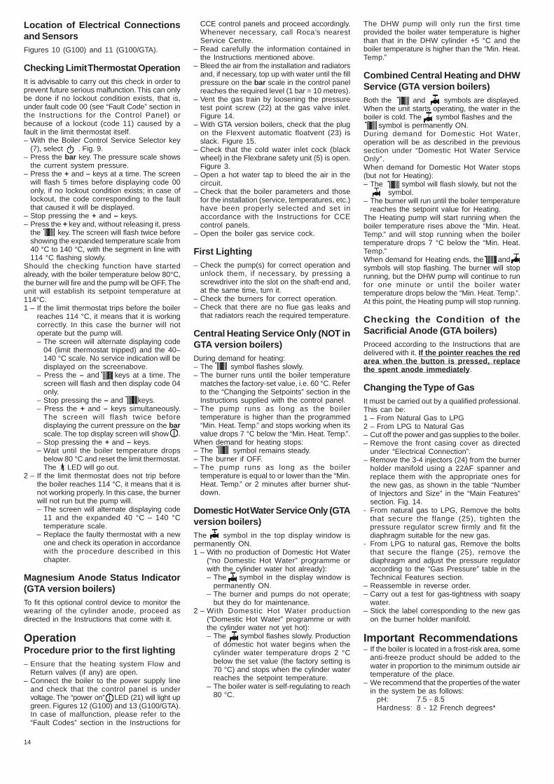
Location of Electrical Connectionsand SensorsFigures 10 (G100) and 11 (G100/GTA).
Checking Limit Thermostat OperationIt is advisable to carry out this check in order toprevent future serious malfunction. This can onlybe done if no lockout condition exists, that is,under fault code 00 (see “Fault Code” section inthe Instructions for the Control Panel) orbecause of a lockout (code 11) caused by afault in the limit thermostat itself.– With the Boiler Control Service Selector key
(7), select . Fig. 9.– Press the bar key. The pressure scale shows
the current system pressure.– Press the + and – keys at a time. The screen
will flash 5 times before displaying code 00only, if no lockout condition exists; in case oflockout, the code corresponding to the faultthat caused it will be displayed.
– Stop pressing the + and – keys.– Press the + key and, without releasing it, press
the key. The screen will flash twice beforeshowing the expanded temperature scale from40 °C to 140 °C, with the segment in line with114 °C flashing slowly.
Should the checking function have startedalready, with the boiler temperature below 80°C,the burner will fire and the pump will be OFF. Theunit will establish its setpoint temperature at114°C.1 – If the limit thermostat trips before the boiler
reaches 114 °C, it means that it is workingcorrectly. In this case the burner will notoperate but the pump will.– The screen will alternate displaying code
04 (limit thermostat tripped) and the 40–140 °C scale. No service indication will bedisplayed on the screenabove.
– Press the – and keys at a time. Thescreen will flash and then display code 04only.
– Stop pressing the – and keys.– Press the + and – keys simultaneously.
The screen will flash twice beforedisplaying the current pressure on the barscale. The top display screen will show .
– Stop pressing the + and – keys.– Wait until the boiler temperature drops
below 80 °C and reset the limit thermostat.The LED will go out.
2 – If the limit thermostat does not trip beforethe boiler reaches 114 °C, it means that it isnot working properly. In this case, the burnerwill not run but the pump will.– The screen will alternate displaying code
11 and the expanded 40 °C – 140 °Ctemperature scale.
– Replace the faulty thermostat with a newone and check its operation in accordancewith the procedure described in thischapter.
Magnesium Anode Status Indicator(GTA version boilers)To fit this optional control device to monitor thewearing of the cylinder anode, proceed asdirected in the Instructions that come with it.
OperationProcedure prior to the first lighting– Ensure that the heating system Flow and
Return valves (if any) are open.– Connect the boiler to the power supply line
and check that the control panel is undervoltage. The “power on” LED (21) will light upgreen. Figures 12 (G100) and 13 (G100/GTA).In case of malfunction, please refer to the“Fault Codes” section in the Instructions for
CCE control panels and proceed accordingly.Whenever necessary, call Roca’s nearestService Centre.
– Read carefully the information contained inthe Instructions mentioned above.
– Bleed the air from the installation and radiatorsand, if necessary, top up with water until the fillpressure on the bar scale in the control panelreaches the required level (1 bar = 10 metres).
– Vent the gas train by loosening the pressuretest point screw (22) at the gas valve inlet.Figure 14.
– With GTA version boilers, check that the plugon the Flexvent automatic floatvent (23) isslack. Figure 15.
– Check that the cold water inlet cock (blackwheel) in the Flexbrane safety unit (5) is open.Figure 3.
– Open a hot water tap to bleed the air in thecircuit.
– Check that the boiler parameters and thosefor the installation (service, temperatures, etc.)have been properly selected and set inaccordance with the Instructions for CCEcontrol panels.
– Open the boiler gas service cock.
First Lighting– Check the pump(s) for correct operation and
unlock them, if necessary, by pressing ascrewdriver into the slot on the shaft-end and,at the same time, turn it.
– Check the burners for correct operation.– Check that there are no flue gas leaks and
that radiators reach the required temperature.
Central Heating Service Only (NOT inGTA version boilers)During demand for heating:– The symbol flashes slowly.– The burner runs until the boiler temperature
matches the factory-set value, i.e. 60 °C. Referto the “Changing the Setpoints” section in theInstructions supplied with the control panel.
– The pump runs as long as the boilertemperature is higher than the programmed“Min. Heat. Temp.” and stops working when itsvalue drops 7 °C below the “Min. Heat. Temp.”.
When demand for heating stops:– The symbol remains steady.– The burner if OFF.– The pump runs as long as the boiler
temperature is equal to or lower than the “Min.Heat. Temp.” or 2 minutes after burner shut-down.
Domestic Hot Water Service Only (GTAversion boilers)The symbol in the top display window ispermanently ON.1 – With no production of Domestic Hot Water
(“no Domestic Hot Water” programme orwith the cylinder water hot already):– The symbol in the display window is
permanently ON.– The burner and pumps do not operate;
but they do for maintenance.2 – With Domestic Hot Water production
(“Domestic Hot Water” programme or withthe cylinder water not yet hot):– The symbol flashes slowly. Production
of domestic hot water begins when thecylinder water temperature drops 2 °Cbelow the set value (the factory setting is70 °C) and stops when the cylinder waterreaches the setpoint temperature.
– The boiler water is self-regulating to reach80 °C.
The DHW pump will only run the first timeprovided the boiler water temperature is higherthan that in the DHW cylinder +5 °C and theboiler temperature is higher than the “Min. Heat.Temp.”
Combined Central Heating and DHWService (GTA version boilers)Both the and symbols are displayed.When the unit starts operating, the water in theboiler is cold. The symbol flashes and the symbol is permanently ON.During demand for Domestic Hot Water,operation will be as described in the previoussection under “Domestic Hot Water ServiceOnly”.When demand for Domestic Hot Water stops(but not for Heating):– The symbol will flash slowly, but not the
symbol.– The burner will run until the boiler temperature
reaches the setpoint value for Heating.The Heating pump will start running when theboiler temperature rises above the “Min. Heat.Temp.” and will stop running when the boilertemperature drops 7 °C below the “Min. Heat.Temp.”When demand for Heating ends, the andsymbols will stop flashing. The burner will stoprunning, but the DHW pump will continue to runfor one minute or until the boiler watertemperature drops below the “Min. Heat. Temp.”.At this point, the Heating pump will stop running.
Checking the Condition of theSacrificial Anode (GTA boilers)Proceed according to the Instructions that aredelivered with it. If the pointer reaches the redarea when the button is pressed, replacethe spent anode immediately.
Changing the Type of GasIt must be carried out by a qualified professional.This can be:1 – From Natural Gas to LPG2 – From LPG to Natural Gas– Cut off the power and gas supplies to the boiler.– Remove the front casing cover as directed
under “Electrical Connection”.– Remove the 3-4 injectors (24) from the burner
holder manifold using a 22AF spanner andreplace them with the appropriate ones forthe new gas, as shown in the table “Numberof Injectors and Size” in the “Main Features”section. Fig. 14.
- From natural gas to LPG, Remove the boltsthat secure the flange (25), tighten thepressure regulator screw firmly and fit thediaphragm suitable for the new gas.
- From LPG to natural gas, Remove the boltsthat secure the flange (25), remove thediaphragm and adjust the pressure regulatoraccording to the “Gas Pressure” table in theTechnical Features section.
– Reassemble in reverse order.– Carry out a test for gas-tightness with soapy
water.– Stick the label corresponding to the new gas
on the burner holder manifold.
Important Recommendations– If the boiler is located in a frost-risk area, some
anti-freeze product should be added to thewater in proportion to the minimum outside airtemperature of the place.
– We recommend that the properties of the waterin the system be as follows:
pH: 7.5 - 8.5Hardness: 8 - 12 French degrees*

15
* One French degree is equivalent to 1 gram of calciumcarbonate per 100 litres of water.
– Should it become necessary to add water tothe system, wait until the boiler is completelycold before doing so.
These boilers are fitted with a safety systemthat operates based on the improper removal offlue gases, thus causing the gas valve to close.Once the fault condition has been cleared, itcan be reset by pressing on “RESET” (26).Figure 16.
Only parts supplied by the manufacturer can beused to replace faulty ones.Should the boiler lock out repeatedly, the fluegas removal problem must be solved by adoptingthe appropriate measures.Carry out a run test following any operation,change or adjustment.– Limiting the noise level in the system.Should the risk of nuisance noise level exist, thefollowing steps can be adopted:– Insulate the pump.– Insulate the boiler, if necessary.– Lay the pipes with vibration isolation stays/
mounts.– Re-size the pipes.– Limit the number of elbows and non-insulated
built-in pipes.
Note:Specifications and performance qualities aresubject to change without notice.
CE MarkedThe G100 IE-XIE Confort and G100 IE-XIE/GTAConfort boilers are certified to comply withthe essential requirements of theElectromagnetic Compatibility Directive89/336/EEC, the Gas Appliances Directive90/396/EEC, the Low Voltage Directive73/23/EEC, and the Energy EfficiencyDirective 92/42/EEC, and are thereforepermitted to carry the CE mark.

2-69
60-1
-060
5-C
E©
Bax
i Roc
a C
alef
acci
ón, S
.L.
L'H
ospi
tale
t de
Llob
rega
t 20
05