g seismic - vertebra
TRANSCRIPT
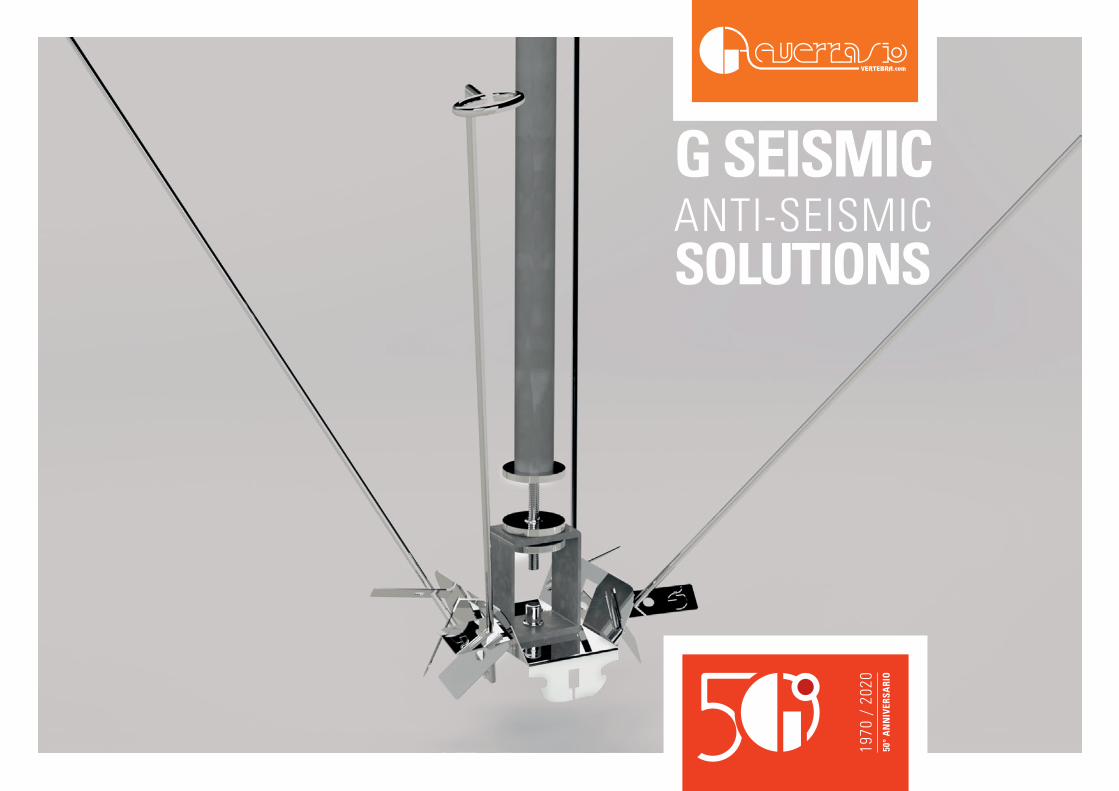
G SEISMICANTI-SEISMIC SOLUTIONS

2
The anti-seismic solution for all false ceilings on metal structure.G SEISMIC
3
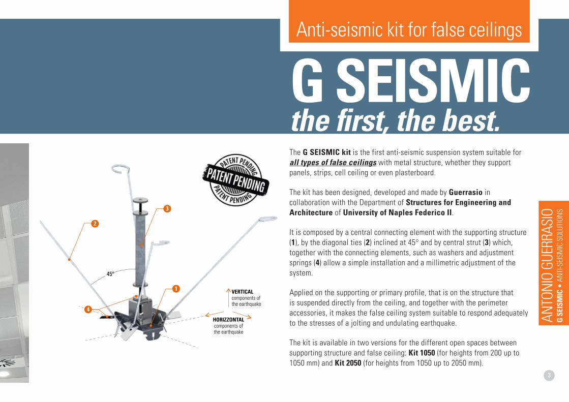
The G SEISMIC kit is the first anti-seismic suspension system suitable for all types of false ceilings with metal structure, whether they support panels, strips, cell ceiling or even plasterboard.
The kit has been designed, developed and made by Guerrasio in collaboration with the Department of Structures for Engineering and Architecture of University of Naples Federico II.
It is composed by a central connecting element with the supporting structure (1), by the diagonal ties (2) inclined at 45° and by central strut (3) which, together with the connecting elements, such as washers and adjustment springs (4) allow a simple installation and a millimetric adjustment of the system.
Applied on the supporting or primary profile, that is on the structure that is suspended directly from the ceiling, and together with the perimeter accessories, it makes the false ceiling system suitable to respond adequately to the stresses of a jolting and undulating earthquake.
The kit is available in two versions for the different open spaces between supporting structure and false ceiling: Kit 1050 (for heights from 200 up to 1050 mm) and Kit 2050 (for heights from 1050 up to 2050 mm).
G SEISMIC the first, the best.
HORIZZONTALcomponents ofthe earthquake
VERTICAL components ofthe earthquake
1
2
3
4
45°
Anti-seismic kit for false ceilings
ANTO
NIO
GUER
RASI
OG
SEIS
MIC
• A
NTI-S
EISM
IC S
OLUT
IONS
4
G SE
ISM
IC K
itN
orm
ativ
e re
quire
men
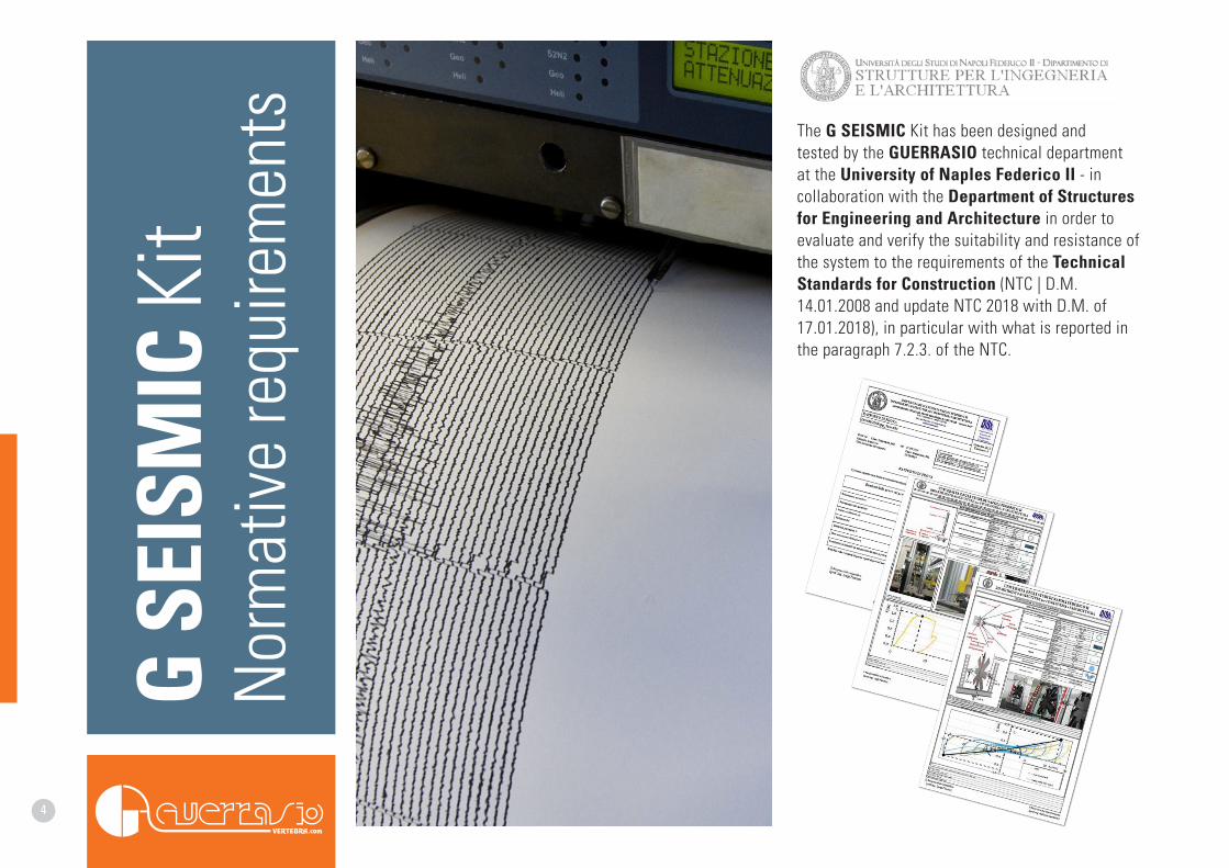
ts The G SEISMIC Kit has been designed and tested by the GUERRASIO technical department at the University of Naples Federico II - in collaboration with the Department of Structures for Engineering and Architecture in order to evaluate and verify the suitability and resistance of the system to the requirements of the Technical Standards for Construction (NTC | D.M. 14.01.2008 and update NTC 2018 with D.M. of 17.01.2018), in particular with what is reported in the paragraph 7.2.3. of the NTC.
5
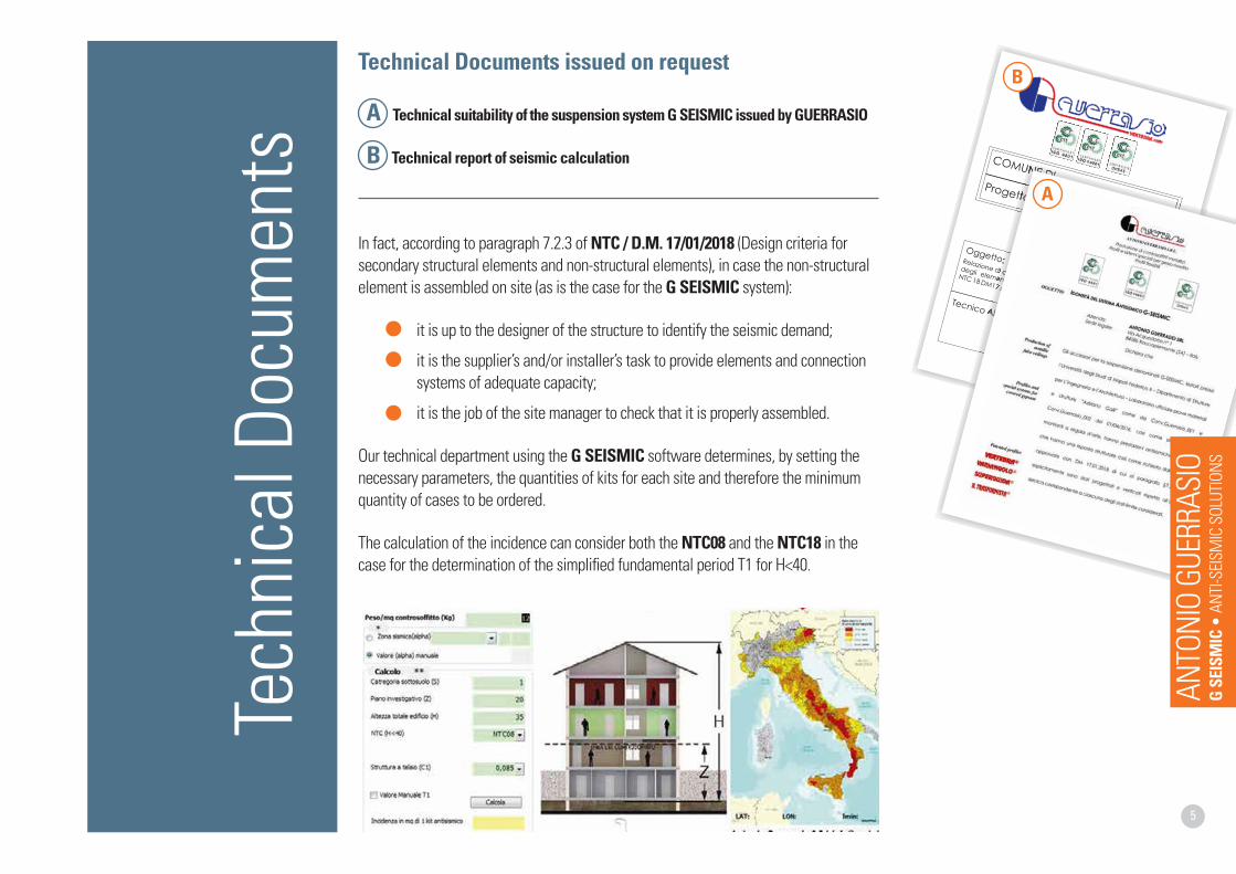
Technical Documents issued on request
A Technical suitability of the suspension system G SEISMIC issued by GUERRASIO
B Technical report of seismic calculation
In fact, according to paragraph 7.2.3 of NTC / D.M. 17/01/2018 (Design criteria for secondary structural elements and non-structural elements), in case the non-structural element is assembled on site (as is the case for the G SEISMIC system):
• it is up to the designer of the structure to identify the seismic demand;
• it is the supplier’s and/or installer’s task to provide elements and connection systems of adequate capacity;
• it is the job of the site manager to check that it is properly assembled.
Our technical department using the G SEISMIC software determines, by setting the necessary parameters, the quantities of kits for each site and therefore the minimum quantity of cases to be ordered.
The calculation of the incidence can consider both the NTC08 and the NTC18 in the case for the determination of the simplified fundamental period T1 for H<40.
Tech
nica
l Doc
umen
tsA
B
ANTO
NIO
GUER
RASI
OG
SEIS
MIC
• A
NTI-S
EISM
IC S
OLUT
IONS
6
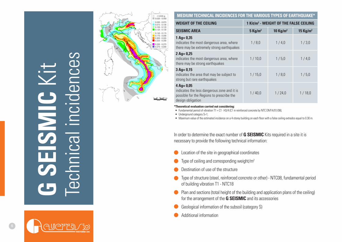
In order to determine the exact number of G SEISMIC Kits required in a site it is necessary to provide the following technical information:
• Location of the site in geographical coordinates
• Type of ceiling and corresponding weight/m2
• Destination of use of the structure
• Type of structure (steel, reinforced concrete or other) - NTC08, fundamental period of building vibration T1 - NTC18
• Plan and sections (total height of the building and application plans of the ceiling) for the arrangement of the G SEISMIC and its accessories
• Geological information of the subsoil (category S)
• Additional information
G SE
ISM
IC K
itTe
chni
cal i
ncid
ence
s
MEDIUM TECHNICAL INCIDENCES FOR THE VARIOUS TYPES OF EARTHQUAKE*
WEIGHT OF THE CEILING 1 Kit/m2 - WEIGHT OF THE FALSE CEILING
SEISMIC AREA 5 Kg/m2 10 Kg/m2 15 Kg/m2
1 Ag= 0,35indicates the most dangerous area, where there may be extremely strong earthquakes
1 / 8,0 1 / 4,0 1 / 3,0
2 Ag= 0,25indicates the most dangerous area, where there may be strong earthquakes
1 / 10,0 1 / 5,0 1 / 4,0
3 Ag= 0,15indicates the area that may be subject to strong but rare earthquakes
1 / 15,0 1 / 8,0 1 / 5,0
4 Ag= 0,05indicates the less dangerous zone and it is possible for the Regions to prescribe the design obligation
1 / 40,0 1 / 24,0 1 / 18,0
*Theoretical evaluation carried out considering:• Fundamental period of vibration T1 = C1 ∙ H3/4 (C1 in reinforced concrete by NTC DM14/01/08);• Underground category S=1;• Maximum value of the estimated incidence on a 4-storey building on each floor with a false ceiling extrados equal to 0.30 m.
7
G SE
ISM
IC K
itON
T-S
TRUC
TURE
ANTO
NIO
GUER
RASI
OG
SEIS
MIC
• A
NTI-S
EISM
IC S
OLUT
IONS
8
Locked profile
Locked profile
Free profile
Free profile
Free profile
Det. B
Det. BDet. A
Perimeter
TBØ4
PP3700
IC600
IL1200SPPT
G SEISMIC
Sec. B
Sec. A
Det. AFr
ee p
rofil
e
Lock
ed p
rofil
e
VISIO SEMI VISIO VERT LAB VERT TILE VERT BOX VERT PAR FLAT
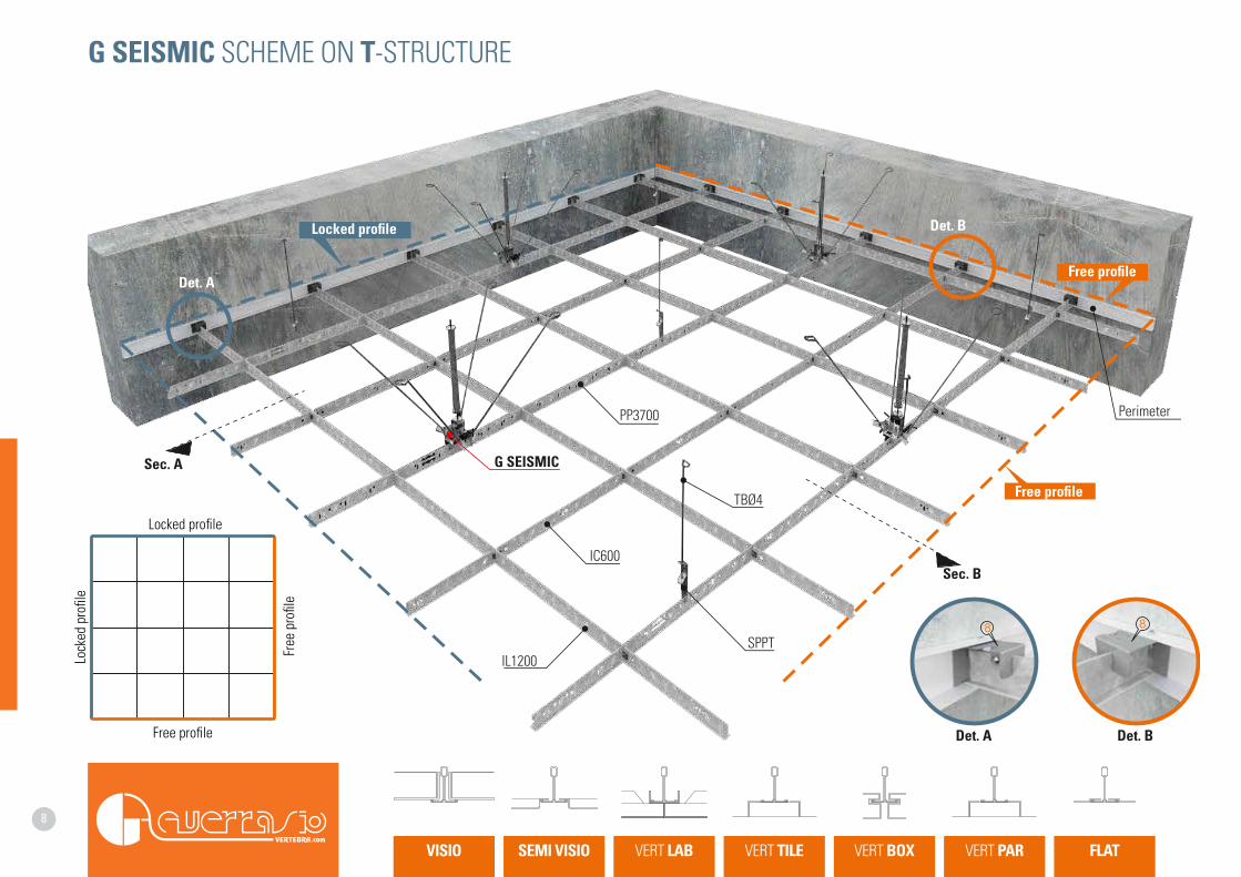
G SEISMIC SCHEME ON T-STRUCTURE
9
11
4 43 3
5 5
77
120 120
92
44
11030
INSTALLATIONON SITE
INSTALLATIONON SITE
2
2
6
6
REGULATIONREGULATION
CEILING CEILING
Sec. A Det. C
Det. C
Sec. B Det. E
Det. E
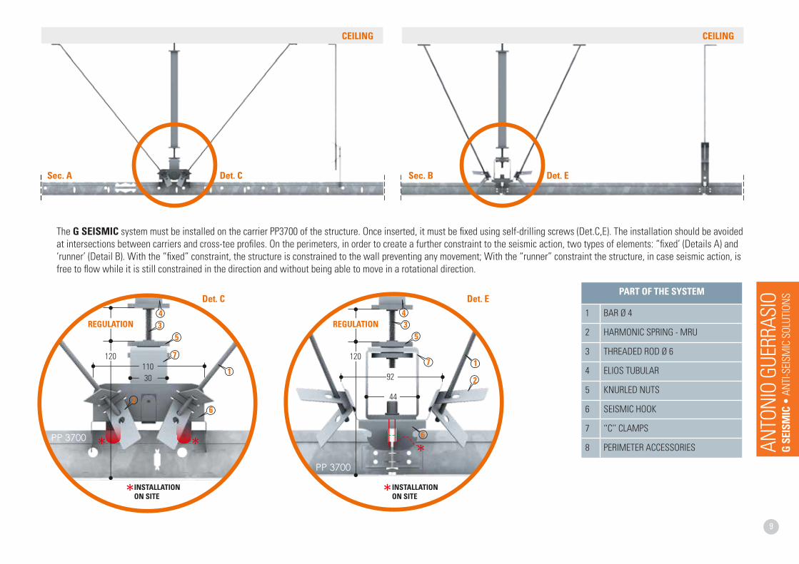
The G SEISMIC system must be installed on the carrier PP3700 of the structure. Once inserted, it must be fixed using self-drilling screws (Det.C,E). The installation should be avoided at intersections between carriers and cross-tee profiles. On the perimeters, in order to create a further constraint to the seismic action, two types of elements: “fixed’ (Details A) and ‘runner’ (Detail B). With the “fixed” constraint, the structure is constrained to the wall preventing any movement; With the “runner” constraint the structure, in case seismic action, is free to flow while it is still constrained in the direction and without being able to move in a rotational direction.
PART OF THE SYSTEM
1 BAR Ø 4
2 HARMONIC SPRING - MRU
3 THREADED ROD Ø 6
4 ELIOS TUBULAR
5 KNURLED NUTS
6 SEISMIC HOOK
7 ‘‘C’’ CLAMPS
8 PERIMETER ACCESSORIES ANTO
NIO
GUER
RASI
OG
SEIS
MIC
• A
NTI-S
EISM
IC S
OLUT
IONS
10
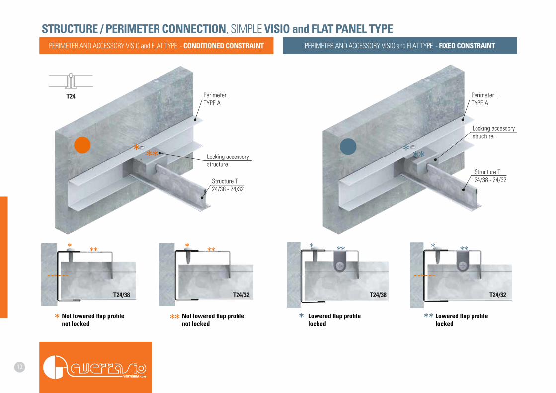
T24
T24/38 T24/32 T24/38 T24/32
Structure T24/38 - 24/32
Structure T24/38 - 24/32
Locking accessorystructure
Locking accessorystructure
Perimeter TYPE A
Perimeter TYPE A
Not lowered flap profile not locked
Not lowered flap profile not locked
Lowered flap profile locked
Lowered flap profile locked
STRUCTURE / PERIMETER CONNECTION, SIMPLE VISIO and FLAT PANEL TYPEPERIMETER AND ACCESSORY VISIO and FLAT TYPE - CONDITIONED CONSTRAINT PERIMETER AND ACCESSORY VISIO and FLAT TYPE - FIXED CONSTRAINT

11
G SE
ISM
IC K
itON
PRO
FILES
FOR
PLAS
TERB
OARD
ANTO
NIO
GUER
RASI
OG
SEIS
MIC
• A
NTI-S
EISM
IC S
OLUT
IONS
12
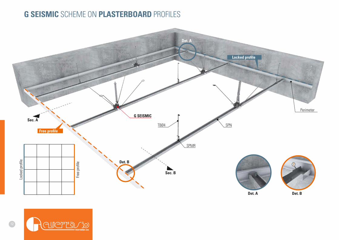
Locked profile
Free profile
Det. B
Det. B
Det. A
Perimeter
TBØ4
SPMR
SPN
G SEISMIC
Det. A
Free
pro
file
Lock
ed p
rofil
e
Sec. B
Sec. A
G SEISMIC SCHEME ON PLASTERBOARD PROFILES
13
1 1
4 4
33
5 5
77
92
44
11030
INSTALLATIONON SITE
2 26
6
MAX15 MAX
15
CEILING CEILING
Sec. A Det. C
Det. C
Sec. B Det. E
Det. EPART OF THE SYSTEM
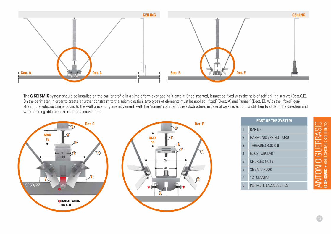
1 BAR Ø 4
2 HARMONIC SPRING - MRU
3 THREADED ROD Ø 6
4 ELIOS TUBULAR
5 KNURLED NUTS
6 SEISMIC HOOK
7 ‘‘C’’ CLAMPS
8 PERIMETER ACCESSORIES
The G SEISMIC system should be installed on the carrier profile in a simple form by snapping it onto it. Once inserted, it must be fixed with the help of self-drilling screws (Dett.C,E). On the perimeter, in order to create a further constraint to the seismic action, two types of elements must be applied: ‘fixed’ (Dect. A) and ‘runner’ (Dect. B). With the “fixed” con-straint, the substructure is bound to the wall preventing any movement; with the ‘runner’ constraint the substructure, in case of seismic action, is still free to slide in the direction and without being able to make rotational movements.
ANTO
NIO
GUER
RASI
OG
SEIS
MIC
• A
NTI-S
EISM
IC S
OLUT
IONS
14
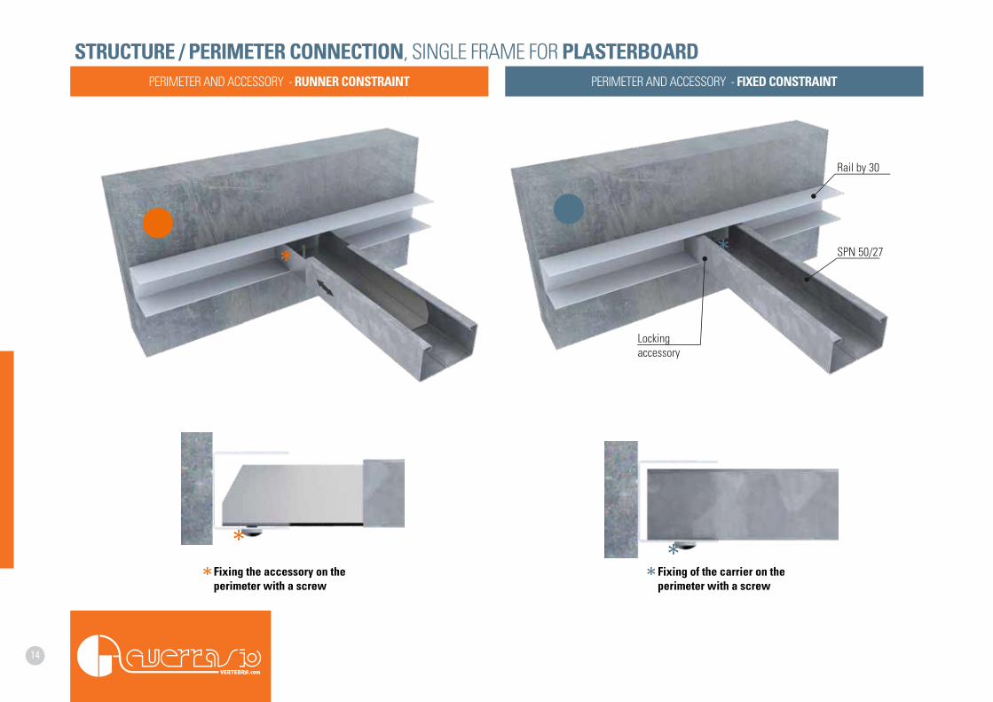
Lockingaccessory
Rail by 30
SPN 50/27
Fixing the accessory on the perimeter with a screw
Fixing of the carrier on the perimeter with a screw
STRUCTURE / PERIMETER CONNECTION, SINGLE FRAME FOR PLASTERBOARDPERIMETER AND ACCESSORY - RUNNER CONSTRAINT PERIMETER AND ACCESSORY - FIXED CONSTRAINT
15
ANTO
NIO
GUER
RASI
OG
SEIS
MIC
• A
NTI-S
EISM
IC S
OLUT
IONS
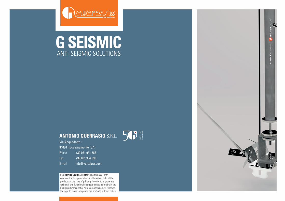
ANTONIO GUERRASIO S.R.L.Via Acquedotto 1
84086 Roccapiemonte (SA)
Phone
Fax
+39 081 931 788
+39 081 934 933
FEBRUARY 2020 EDITION • The technical data contained in this publication are the actual data of the products at the time of printing. In order to improve the technical and functional characteristics and to obtain the best quality/price ratio, Antonio Guerrasio s.r.l. reserves the right to make changes to the products without notice.
GS2
019
IT •
R03
• 0
3/03
/202
0G SEISMIC ANTI-SEISMIC SOLUTIONS