g series - equind.com.mx · 4 nash_elmo industries g_series g_200 single-stage version. g_400...
TRANSCRIPT
G_SeriesGas Ring Blowers
US Edition
2 nash_elmo Industries G_Serie
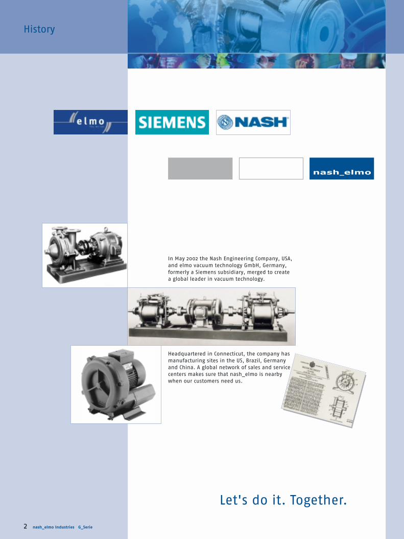
History
Let's do it. Together.
In May 2002 the Nash Engineering Company, USA,
and elmo vacuum technology GmbH, Germany,
formerly a Siemens subsidiary, merged to create
a global leader in vacuum technology.
Headquartered in Connecticut, the company has
manufacturing sites in the US, Brazil, Germany
and China. A global network of sales and service
centers makes sure that nash_elmo is nearby
when our customers need us.

nash_elmo Industries G_Series 3
G_Series Gas ring blowers and compressors
Contents
Series overview 4 - 5
Selection and ordering information
G_100 6 - 9
G_200 10 - 19
G_200e (with frequency converter) 20 - 25
G_400 26 - 29
G_400e (with frequency converter) 30 - 33
Accessories – selection and ordering information 34 - 43
Dimensions – gas ring compressors 44 - 58
Dimensions – accessories 59 - 63
Annex
Application examples 66 - 75
Conversion tables 76
Physical basics for blower applications 77 - 78
General safety information 79 - 80
Quality 81
ATEX 82
Footnotes and Voltage Overview 83
Some technologies are so good that it’s hard to improve them. Gas ring blowers from
nash_elmo are such an example. They’ve proven their reliability in service for many decades,
performing flawlessly day in and day out with virtually no down time. Existing noise levels
have been lower than that of most other vacuum pumps and compressors.
G_Series pumps and compressors are used for conveying gases and gas-air mixtures.
Main features: ■ Low noise level
■ Low Maintenance
■ Reliable and built-to-last
■ Robust yet light-weight
■ Can be installed in any axial orientation
■ Wide performance range
■ For use worldwide (UL/CSA/IEC/EN approval)
■ 50/60 Hz voltage range motors
■ ATEX 94/9 EG
1,800
1,200
600
300
180
150
120
90
60
30
1
Su
cti
on
cap
acit
y V
G_200
G_400
cfm
inch H2O
G_100
-280 -240 -200 -160 -120 -80 -40 40 80 120 160 200 240 280 320 360 400 440
Vacuum Pressure

4 nash_elmo Industries G_Series
G_200
Single-stage version.
G_400
Multi-stage, reliability for
high differential pressures
G_200
Two-stage, for tougher
requirements.
G_400e
With integrated frequency
converter.
G_200e and G_400e also
available with external
frequency converter
G_200e
With integrated frequency
converter for high volume
flows and/or automatic
modification to changing loads.
G_400
Single-stage, for high
pressure ranges.
G_100
Driven via an electronically commu-
tated, permanent-field DC motor.
Infinitely variable over the entire
power range.
Applications
■ Pneumatic conveying systems
■ Lifting and holding of parts by vacuum
■ Packaging machines
■ Aeration of sewage-treatment plants
■ Filling of bags/bottles/hoppers
■ Soil remediation
■ Thermoforming
■ Sorting/enveloping of letters
■ Food-processing
■ Laser printers
■ Dental suction equipment
■ Paper processing
■ Printers/copiers
■ Textile machines
■ Aeration of fish ponds
■ Gas analysis
■ Swimming-pool equipment/whirlpools
G_Series Gas ring blowers and compressors

nash_elmo Industries G_Series 5
G_Series – operating principle
The impellers in the G_Series machines are mounted directly on the motor shaft for non-
contact compression entirely without friction. Maximum operational reliability, even at
high differential pressures, is ensured by the arrangement of the bearings outside the
compression chamber.
The gas is taken in through the inlet 1. As it enters the side channel 2, the rotating
impeller 3 imparts velocity to the gas in the direction of rotation.
Centrifugal force in the impeller blades accelerates the gas outward and the pressure
increases. Every rotation adds kinetic energy, resulting in further increase of pressure
along the side channel.
The side channel narrows at
the rotor, sweeping the gas
off the impeller blades and
discharging it through the
outlet silencer 4 where it
exits the pump.
The G_Series vacuum pumps and compressors are available in a wide selection for perfor-
mance ranges up to 1,770 cfm and differential pressures of up to 400 inch H2O. They cover
the most varied requirements flexibly and powerfully. If frequency converters are used,
any operating point can be precisely selected, maintained and controlled. These conver-
ters can be integrated into the machine but are also available as stand-alone models.
Ex stock for use world-wide
The G_Series pumps and compressors feature voltage range motors for 50 and 60 Hz in
protection class IP 55 (insulation class F) and are UL 507 and CSA 22.2. No. 113 approved.
This makes them the ideal solution for world-wide use: they can be used without modifi-
cations or tests in Europe, Asia and America. They are mostly available ex stock.
Large range of accessories
nash-elmo offers a large range of accessories for our G_series that are ideally suited for
these machines.
A special sound protection hood was designed for noise sensitive environments such as
schools, living quarters, hospitals and production facilities. They can be installed outside,
are maintenance-free and easy to transport.
An additional rigid silencer is now available for the G_200 that will reduce the noise level
even further.
2 side channel
3 impeller
4 outlet
1 inlet

G_100

The smallest gas ring blower
on the market
With a height and width of approx. 5 inches and a depth of approx. 2.4
inches, the G_100 blowers have the size of a CD and are the smallest gas
ring vacuum blowers available on the market. Furthermore, the adjustable
volume flow of the machines ensures that only the exact performance
required is actually being supplied — not more.
These blowers are employed primarily in fine mechanical and medical
technology applications. With their robust and built-to-last design, they
are also used in other industries such as mechanical engineering.
The G_100 is driven via an electronically commuted DC motor. This guaran-
tees a high level of efficiency and maintenance-free operation for more
than 20,000 operating hours. The operating electronics are a standard
feature of the machines which allow infinitely variable control of speed
and output of the blower.
Selection diagram, ordering information, pages 8 - 9
accessories, dimensions
G_100

8 nash_elmo Industries G_Series
Selection and ordering information
The performance curves are valid for pumping air at 60 °F (15 °C) at the inlet flanges
with an air pressure of 29,9 in Hg abs. (1,013 mbar) and a tolerance of ±10%. The total
pressure differences are valid up to an intake and ambient temperature of 77 °F (25 °C).
G_Series G_100
Curve no.Speed n
min-1
output
hp
voltage
V
current
A
Order no. Weight
lbs
Control voltage(0...10 V DC)
V
Soundpressurelevel1)
dB(A)
Max. differentialvacuum com-pump pressorin H2O in H2O
Rated
Vacuum-compressor selection diagram
IP66, with hood and integrated electronicsC100 2BH1 000-0AB32 0.12 24 DC 4.5 – – 48 2.2nmax. 10. 36.9 35.77000 7.15 ± 0.1 32.5 35.36000 6.1 ± 0.1 27.3 28.95000 5.1 ± 0.1 20.9 22.14000 4.05 ± 0.1 13.6 14.53000 3.05 ± 0.1 8.0 8.4
C150 2BH1 000-0AA53 2) 0.38 48 DC 8 72.3 80.3 50 2.6
IP 66, with external electronics
24
18
12
6
080 60 40 20 0 20 40 60 80
C100
C150
uG_5351b
in H2O
cfm
(Vacuum) Total pressure difference (Pressure)
Su
cti
on
cap
acit
y
Variant “without hood” available on request.
1) Measuring-surface sound-pressure level acc. to EN 21680-1, measured at 1 m distance with
closed suction and pressure side at 7,400 min-1.
Tolerance: ± 3 dB(A).
2) External operating electronics compulsory

*)
PV-5349
e
d
fa
bc
PV
-535
0
R
R1
B1 B
FR2
AN
PV-5348
∅
S1
S2
E
S
R
B2B1B
D
G1
for 2BH1 000-0AA53
G K
d1d2
C
F3
F2F
F4
uG_5
347b
.87 Ø.17
.87
E2.75
ØØ
Ø
55°
70°
nash_elmo Industries G_Series 9
EExxtteerrnnaall eelleeccttrroonniiccss ((VVaarriioottrroonniicc))
2BX4 130
RRuubbbbeerr bbuuffffeerr
2BX4 132
SSeett ooff pplluuggss
2BX4 131
S1 Control signal
S2 Motor connection
Accessories for 2BH100
Delivery looseOrder no.
Weight approx.lbs
Delivery with the pumpabbreviation1)
External electronics (Variotronic)2), loose 2BX4 130 B30 0.44Set of plugs3), loose, eight-pole, for connecting motor Variotronic, 2BX4 131 B20 –comprising:1 x socket casing, 3 x socket contact AWG 205 x socket contact AWG 26, 2 x 1 each spare contactSuction filter 2BX4 134 B36 0.66Silencer 2BX4 135 B37 0.22Rubber buffer (1 set = 4 pieces) (rubber metal bearing) 2BX4 132 B31 –
Dimensions for 2BH100 (inch)
Dimensional drawings are also available as .dxf files on request.
Dimensions of accessories for 2BH100 (inch)
*) 2BX4 131: Pliers not included in scope of order
1) Please add a „--ZZ“ to the order number and add the abbreviation as follows: Example 2BH1 000-0AB32-ZZ
BB3300 ++ BB3311
2) With ambient temperatures over 25°C the operating speed may be less depending on the cooling of the electronics system.
3) Note: Pliers for the socket contacts are not included with delivery; obtainable from Molex Deutschland/Heilbronn; Germany
Fax +49 (0) 70 66 / 95 55 29; Type 69008-0274.
Type B B1 B2 C D Ø d1 Ø d2 E F F2 F3 F4 G G1 K Ø R S
2BH1 000-0AB32 5.7 5.2 4.8 3.5 2.8 0.8 0.7 2.1 2.6 1.1 0.3 0.6 0.4 0.04 17.7 0.2 0.42BH1 000-0AA53 3.7 2.4 3.6
Order no. A B B1 F N Ø R R1 R22BX4 130 4.41 3.62 3.15 3.31 0.51 0.26 0.12 0.22Order no. a b c d e f2BX4 132 Ø0.39 0.39 0.39 0.16 M 4 M 4

G_200
G_20
0
G_200 single
and multi-stage
G_200e with integrated or external
frequency converter

G_200Classics with innovative technology
With their high inlet volume flow (up to 1,470 cfm) and a differential pres-
sure of up to 313 inch H2O, our low noise G_series allrounders have
earned their reputation and convinced thousands of customers all over
the world.
They are reliable, low-maintenance and durable and are the first choice
for many applications in mechanical engineering.
When used with a frequency converter the performance of the G_200
pumps and compressors can be increased considerably.
The G_200 machines are UL/CSA approved and can be used without
further testing all over the world.
Available at short notice or ex stock and also as ATEX certified models,
the G_200 family is a classic that has proven its innovative quality.
Selection diagrams and tables for G_200, pages 12 - 19
vacuum and compressor mode, 50 and 60 Hz
G_200e, pumps and compressors with speed control pages 20 - 25
and frequency converter
Details on voltages, footnotes etc. see page 83

12 nash_elmo Industries G_Series
G_Series G_200, 50 Hz
Selection diagram, vacuum operation
The performance curves are valid for pumping air at 60 °F (15 °C) at the inlet flanges with
an air pressure of 29,9 in Hg abs. (1,013 mbar) and a tolerance of ±10%. The total pressure
differences are valid up to an intake and ambient temperature of 77 °F (25 °C).
∆Total pressure difference (Vacuum) p
1500
1200
900
700
500
400
300
200
150
100
70
50
40
30
20
1050200 180 160 140 120 100 80 60 40 20 0
0
10
20
40
60
80
100
120
150
200
300
400
500
600
800
1000
1200
1500
2000
2500uG_5013j
cfm m3/h
in H2O
A380
A382
A384
A342
A344=A346
A340
A320
A322
A280
A282
A284A286
A260
A230
A232A234
A236=A238
A200
A262=A264
A202A170=A172s
A170s
A172 A140
A110=A110sA150
A130
A120=A120s
A132s
A132A164
A162
A162s=A164s
A196
A194 A196s A160
A192
A192s
A180
A180s
A190A210
A222
A224
A226
A220
A274
A272
A270
A354A334
A332
A330
A352
A350
A150s
Su
cti
on
cap
acit
y V

nash_elmo Industries G_Series 13
Curve no. Weightapprox.
lbs
Order no. Vacuum-reliefvalve2)
Items x type 2BX2...
Pressure-reliefvalve2)
Items x type2BX2...
Soundpressurelevel1)
dB(A)
MotorRated
output voltage4) currenthp V A
A110 0.27 200-240 B / 345-415 Y 2.1 B / 1.2 Y 2BH1 100-7A H 0 6 15 50 – –A120 0.34 200-240 B / 345-415 Y 1.38 B / 0.8 Y 2BH1 200-7A H 0 6 18 57 – –A130 0.34 200-240 B / 345-415 Y 2.1 B / 1.2 Y 2BH1 300-7A H 0 6 18 53 1 x 110/141 1 x 111/143A132 0.54 200-240 B / 345-415 Y 2.6 B / 1.5 Y 2BH1 300-7A H 1 6 22 53 1 x 110/141 1 x 111/143A140 1 200-240 B / 345-415 Y 3.8 B / 2.2 Y 2BH1 310-7H H 2 6 31 55 1 x 110/141 1 x 111/143A150 0.8 200-240 B / 345-415 Y 2.8 B / 1.6 Y 2BH1 490-7A H 1 6 31 63 – –A160 1 200-240 B / 345-415 Y 3.8 B / 2.2 Y 2BH1 400-7A H 0 6 29 63 1 x 110/141 1 x 111/143A162 1.1 200-240 B / 345-415 Y 4.2 B / 2.4 Y 2BH1 400-7A H 1 6 33 63 1 x 110/141 1 x 111/143A164 1.7 200-240 B / 345-415 Y 6.6 B / 3.8 Y 2BH1 400-7A H 2 6 35 63 1 x 110/141 1 x 111/143A170 2.2 200-240 B / 345-415 Y 7.5 B / 4.3 Y 2BH1 410-7H H 3 6 53 66 1 x 110/141 1 x 111/143A172 3 200-240 B / 345-415 Y 9.7 B / 5.6 Y 2BH1 410-7H H 4 6 60 66 1 x 110/141 1 x 111/143A180 1.5 200-240 B / 345-415 Y 7.5 B / 4.3 Y 2BH1 590-7A H 2 6 46 64 – –A190 1.1 200-240 B / 345-415 Y 4.2 B / 2.4 Y 2BH1 500-7A H 0 6 40 64 1 x 110/145 1 x 111/147A192 1.7 200-240 B / 345-415 Y 6.6 B / 3.8 Y 2BH1 500-7A H 1 6 44 64 1 x 110/145 1 x 111/147A194 2.2 200-240 B / 345-415 Y 7.5 B / 4.3 Y 2BH1 500-7A H 2 6 46 64 1 x 110/145 1 x 111/147A196 3 200-240 B / 345-415 Y 9.7 B / 5.6 Y 2BH1 500-7A H 3 6 55 64 1 x 110/145 1 x 111/147A200 4 200-240 B / 345-415 Y 12.5 B / 7.2 Y 2BH1 510-7H H 4 6 86 72 1 x 110/145 1 x 111/147A202 5.4 200-240 B / 345-415 Y 17.4 B / 10 Y 2BH1 510-7H H 5 6 95 72 1 x 110/145 1 x 111/147A210 3 200-240 B / 345-415 Y 12.5 B / 7.2 Y 2BH1 690-7A H 2 6 68 69 – –A220 2.2 200-240 B / 345-415 Y 8.5 B / 4.9 Y 2BH1 600-7A H 0 6 57 69 1 x 110/145 2 x 111/147A222 3 200-240 B / 345-415 Y 10.0 B / 5.8 Y 2BH1 600-7A H 1 6 64 69 1 x 110/145 1 x 111/147A224 3 200-240 B / 345-415 Y 12.5 B / 7.2 Y 2BH1 600-7A H 2 6 75 69 1 x 110/145 1 x 111/147A226 5.4 200-240 B / 345-415 Y 16.5 B / 9.5 Y 2BH1 600-7A H 3 6 93 69 1 x 110/145 1 x 111/147A230 3 200-240 B / 345-415 Y 9.7 B / 5.6 Y 2BH1 610-7H H 1 6 93 73 1 x 110/145 1 x 111/147A232 3 200-240 B / 345-415 Y 12.5 B / 7.2 Y 2BH1 610-7H H 2 6 104 73 1 x 110/145 1 x 111/147A234 5.8 200-240 B / 345-415 Y 17.3 B / 10 Y 2BH1 610-7H H 3 6 117 73 1 x 110/145 1 x 111/147A236 7.4 200-240 B / 345-415 Y 23 B / 13.3 Y 2BH1 610-7H H 4 6 154 73 1 x 110/145 1 x 111/147A238 10 200-240 B / 345-415 Y 29 B / 16.7 Y 2BH1 610-7H H 5 6 170 73 1 x 110/145 1 x 111/147A260 5.4 200-240 B / 345-415 Y 16.4 B / 9.5 Y 2BH1 640-7G H 3 6 117 74 1 x 110/145 3 x 111/147A262 7.4 200-240 B / 345-415 Y 23 B / 13.3 Y 2BH1 640-7G H 4 6 161 74 1 x 110/145 2 x 111/147A264 10 200-240 B / 345-415 Y 29 B / 16.7 Y 2BH1 640-7G H 5 6 190 74 1 x 110/145 1 x 111/147A270 5.4 200-240 B / 345-415 Y 16.4 B / 9.5 Y 2BH1 800-7A H 0 6 247 70 2 x 110 2 x 111A272 7.4 200-240 B / 345-415 Y 23 B / 13.3 Y 2BH1 800-7A H 1 6 278 70 1 x 110 1 x 111A274 10 200-240 B / 345-415 Y 29 B / 16.7 Y 2BH1 800-7A H 2 6 282 70 1 x 110 1 x 111A280 7.4 200-240 B / 345-415 Y 23 B / 13.3 Y 2BH1 810-7H H 1 6 359 74 1 x 110 2 x 111A282 10 200-240 B / 345-415 Y 29 B / 16.7 Y 2BH1 810-7H H 2 6 373 74 1 x 110 2 x 111A284 14.8 200-240 B / 345-415 Y 48.5 B / 28 Y 2BH1 810-7H H 3 6 452 74 1 x 110 1 x 111A286 20.1 200-240 B / 345-415 Y 56.5 B / 32.5 Y 2BH1 810-7H H 4 6 487 74 1 x 110 1 x 111A320 10 200-240 B / 345-415 Y 30.8 B / 17.6 Y 2BH1 840-7J H 2 6 353 74 3 x 110 1 x 151A322 14.8 200-240 B / 345-415 Y 48.5 B / 28 Y 2BH1 840-7J H 3 6 441 74 2 x 110 2 x 111A330 11.4 200-240 B / 345-415 Y 33 B / 19.1 Y 2BH1 900-7A H 0 6 379 74 1 x 150 1 x 151A332 16.8 200-240 B / 345-415 Y 48.5 B / 28 Y 2BH1 900-7A H 1 6 421 74 2 x 110 3 x 111A334 24.8 200-240 B / 345-415 Y 64.5 B / 37 Y 2BH1 900-7A H 3 6 450 74 2 x 110 2 x 111A340 16.8 200-240 B / 345-415 Y 48.5 B / 28 Y 2BH1 910-7H H 1 6 584 74 1 x 150 1 x 151A342 22.1 200-240 B / 345-415 Y 60 B / 35 Y 2BH1 910-7H H 2 6 613 74 3 x 110 1 x 151A344 26.8 200-240 B / 345-415 Y 69 B / 40 Y 2BH1 910-7H H 3 6 650 74 3 x 110 3 x 111A346 33.5 200-240 B / 345-415 Y 90 B / 52 Y 2BH1 910-7H H 4 6 717 74 3 x 110 3 x 111A350 11.4 200-240 B / 345-415 Y 33 B / 19.1 Y 2BH1 930-7A H 0 6 384 75 1 x 150 1 x 151A352 16.7 200-240 B / 345-415 Y 48.5 B / 28 Y 2BH1 930-7A H 1 6 425 75 1 x 150 1 x 151A354 24.8 200-240 B / 345-415 Y 64.5 B / 37 Y 2BH1 930-7A H 3 6 454 75 2 x 110 3 x 111A380 20.1 200-240 B / 345-415 Y 59 B / 34 Y 2BH1 943-7G H 2 63) 595 75 1 x 152 1 x 153A382 26.8 200-240 B / 345-415 Y 69 B / 40 Y 2BH1 943-7G H 3 63) 661 75 1 x 152 1 x 153A384 33.5 200-240 B / 345-415 Y 90 B / 52 Y 2BH1 943-7G H 4 63) 728 75 3 x 110 1 x 153
A110s 0.27 230 / 1.5 / 2BH1 100-7A A 0 1 15 50 – –A110s 0.27 115 / 230 2.9 / 1.45 2BH1 100-7A V 0 5 15 50 – –A120s 0.34 115 / 230 3.1 / 1.6 2BH1 200-7A V 0 5 18 57 – –A132s 0.50 115 / 230 5.4 / 2.7 2BH1 300-7A V 1 5 22 53 1 x 110/141 1 x 111/143A150s 0.7 230 / 4.1 / 2BH1 490-7A A 1 1 31 63 – –A162s 1.1 230 / 5.2 / 2BH1 400-7A A 1 1 33 63 1 x 110/141 1 x 111/143A164s 1.5 115 / 230 14.6 / 7.3 2BH1 400-7A V 2 5 35 63 1 x 110/141 1 x 111/143A170s 2 230 / 9.1 / 2BH1 410-7H A 3 1 42 66 1 x 110/141 1 x 111/143A172s 2 115 / 230 22 / 11 2BH1 410-7H V 4 5 53 66 1 x 110/141 1 x 111/143A180s 1.6 230 / 7.9 / 2BH1 590-7A A 2 1 46 64 – –A192s 1.5 230 / 6.9 / 2BH1 500-7A A 1 1 44 64 1 x 110/145 1 x 111/147A196s 2 115 / 230 22 / 11 2BH1 500-7A V 3 5 49 64 1 x 110/145 1 x 111/147
Selection and ordering information for 50 Hz, 1AC, IP55
Details on voltages, footnotes etc. see page 83.
Selection and ordering information for 50 Hz, 3AC, IP55
▲ ▲
nash_elmo Industries G_Series 14
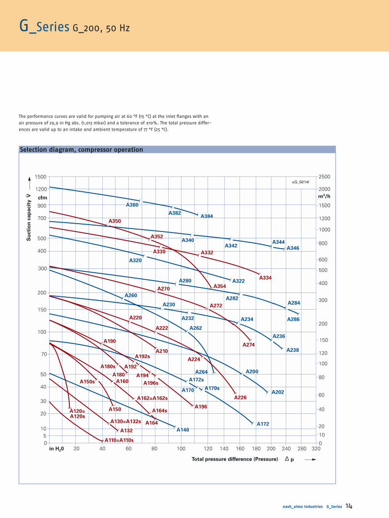
G_Series G_200, 50 Hz
Selection diagram, compressor operation
The performance curves are valid for pumping air at 60 °F (15 °C) at the inlet flanges with an
air pressure of 29,9 in Hg abs. (1,013 mbar) and a tolerance of ±10%. The total pressure differ-
ences are valid up to an intake and ambient temperature of 77 °F (25 °C).
Su
cti
on
cap
acit
y V
1500
1200
cfm
900
700
500
400
300
200
150
100
70
50
40
30
1050
in H20 20 40 60 80 100 120 140 160 180 200 240 280 3200
10
20
40
60
80
100
120
150
200
300
400
500
600
800
1000
1200
1500
2000
2500
m3/h
uG_5014l
A380
A382A384
A340A342
A344
A346
A320
A280 A322
A284
A286
A260
A230
A232 A234
A236
A238
A262
A200A264
A172s
A170sA202A170
A140A172
A132
A110=A110s
A130=A132s
A150A120=A120s
A150s A160
A180
A180s
A162=A162s
A196
A196s
A194
A192
A192s
A164s
A164
A226
A224
A210
A190
A222
A220
A274
A272
A270A354
A330 A332
A334
A352
A350
∆Total pressure difference (Pressure) p
20
A282

nash_elmo Industries G_Series 14nash_elmo Industries G_Series 13
G_Series G_200, 50 Hz
Curve no. Weightapprox.
kg
Order no.
•• Available ex stock
Vacuum-reliefvalve2)
Items x type 2BX2...
Pressure-reliefvalve2)
Items x type2BX2...
Sound-pressurelevel1)
dB(A)
MotorRated-
output voltage4) currentkW V A
A110 0.2 200-240 B / 345-415 Y 2.1 B / 1.2 Y •2BH1 100-7A H 0 6 7 50 – –A120 0.25 200-240 B / 345-415 Y 1.38 B / 0.8 Y •2BH1 200-7A H 0 6 8 57 – –A130 0.25 200-240 B / 345-415 Y 2.1 B / 1.2 Y •2BH1 300-7A H 0 6 8 53 1 x 110/141 1 x 111/143A132 0.4 200-240 B / 345-415 Y 2.6 B / 1.5 Y •2BH1 300-7A H 1 6 10 53 1 x 110/141 1 x 111/143A140 0.7 200-240 B / 345-415 Y 3.8 B / 2.2 Y 2BH1 310-7H H 2 6 14 55 1 x 110/141 1 x 111/143A150 0.6 200-240 B / 345-415 Y 2.8 B / 1.6 Y •2BH1 490-7A H 1 6 14 63 – –A160 0.7 200-240 B / 345-415 Y 3.8 B / 2.2 Y •2BH1 400-7A H 0 6 13 63 1 x 110/141 1 x 111/143A162 0.85 200-240 B / 345-415 Y 4.2 B / 2.4 Y •2BH1 400-7A H 1 6 15 63 1 x 110/141 1 x 111/143A164 1.3 200-240 B / 345-415 Y 6.6 B / 3.8 Y •2BH1 400-7A H 2 6 16 63 1 x 110/141 1 x 111/143A170 1.6 200-240 B / 345-415 Y 7.5 B / 4.3 Y •2BH1 410-7H H 3 6 24 66 1 x 110/141 1 x 111/143A172 2.2 200-240 B / 345-415 Y 9.7 B / 5.6 Y •2BH1 410-7H H 4 6 27 66 1 x 110/141 1 x 111/143A180 1.1 200-240 B / 345-415 Y 7.5 B / 4.3 Y •2BH1 590-7A H 2 6 21 64 – –A190 0.85 200-240 B / 345-415 Y 4.2 B / 2.4 Y •2BH1 500-7A H 0 6 18 64 1 x 110/145 1 x 111/147A192 1.3 200-240 B / 345-415 Y 6.6 B / 3.8 Y •2BH1 500-7A H 1 6 20 64 1 x 110/145 1 x 111/147A194 1.6 200-240 B / 345-415 Y 7.5 B / 4.3 Y •2BH1 500-7A H 2 6 21 64 1 x 110/145 1 x 111/147A196 2.2 200-240 B / 345-415 Y 9.7 B / 5.6 Y •2BH1 500-7A H 3 6 25 64 1 x 110/145 1 x 111/147A200 3 200-240 B / 345-415 Y 12.5 B / 7.2 Y •2BH1 510-7H H 4 6 39 72 1 x 110/145 1 x 111/147A202 4 345-415 B 10 B •2BH1 510-7H H 5 7 43 72 1 x 110/145 1 x 111/147A210 2.2 200-240 B / 345-415 Y 12.5 B / 7.2 Y •2BH1 690-7A H 2 6 31 69 – –A220 1.6 200-240 B / 345-415 Y 8.5 B / 4.9 Y •2BH1 600-7A H 0 6 26 69 1 x 110/145 2 x 111/147A222 2.2 200-240 B / 345-415 Y 10.0 B / 5.8 Y •2BH1 600-7A H 1 6 29 69 1 x 110/145 1 x 111/147A224 3 200-240 B / 345-415 Y 12.5 B / 7.2 Y •2BH1 600-7A H 2 6 34 69 1 x 110/145 1 x 111/147A226 4 345-415 B 9.5 B •2BH1 600-7A H 3 7 42 69 1 x 110/145 1 x 111/147A230 2.2 200-240 B / 345-415 Y 9.7 B / 5.6 Y •2BH1 610-7H H 1 6 42 73 1 x 110/145 1 x 111/147A232 3 200-240 B / 345-415 Y 12.5 B / 7.2 Y •2BH1 610-7H H 2 6 47 73 1 x 110/145 1 x 111/147A234 4..3 345-415 B 10 B •2BH1 610-7H H 3 7 53 73 1 x 110/145 1 x 111/147A236 5.5 345-415 B 13.3 B •2BH1 610-7H H 4 7 70 73 1 x 110/145 1 x 111/147A238 7.5 345-415 B 16.7 B •2BH1 610-7H H 5 7 77 73 1 x 110/145 1 x 111/147A260 4 345-415 B 9.5 B •2BH1 640-7G H 3 7 53 74 1 x 110/145 3 x 111/147A262 5.5 345-415 B 13.3 B •2BH1 640-7G H 4 7 73 74 1 x 110/145 2 x 111/147A264 7.5 345-415 B 16.7 B 2BH1 640-7G H 5 7 86 74 1 x 110/145 1 x 111/147A270 4 345-415 B 9.5 B 2BH1 800-7A H 0 7 112 70 2 x 110 2 x 111A272 5.5 345-415 B 13.3 B •2BH1 800-7A H 1 7 126 70 1 x 110 1 x 111A274 7.5 345-415 B 16.7 B 2BH1 800-7A H 2 7 128 70 1 x 110 1 x 111A280 5.5 345-415 B 13.3 B 2BH1 810-7H H 1 7 163 74 1 x 110 2 x 111A282 7.5 345-415 B 17.6 B •2BH1 810-7H H 2 7 169 74 1 x 110 2 x 111A284 11 345-415 B 28 B •2BH1 810-7H H 3 7 205 74 1 x 110 1 x 111A286 15 345-415 B 32.5 B 2BH1 810-7H H 4 7 221 74 1 x 110 1 x 111A320 7.5 345-415 B 16.7 B •2BH1 840-7J H 2 7 160 74 3 x 110 1 x 151A322 11 345-415 B 28 B •2BH1 840-7J H 3 7 200 74 2 x 110 2 x 111A330 8.5 345-415 B 19.1 B •2BH1 900-7A H 0 7 172 74 1 x 150 1 x 151A332 12.5 345-415 B 28 B •2BH1 900-7A H 1 7 191 74 2 x 110 3 x 111A334 18.5 345-415 B 37 B •2BH1 900-7A H 3 7 204 74 2 x 110 2 x 111A340 12.5 345-415 B 28 B 2BH1 910-7H H 1 7 265 74 1 x 150 1 x 151A342 16.5 345-415 B 35 B •2BH1 910-7H H 2 7 278 74 3 x 110 1 x 151A344 20 345-415 B 40 B •2BH1 910-7H H 3 7 295 74 3 x 110 3 x 111A346 25 345-415 B 52 B 2BH1 910-7H H 4 7 325 74 3 x 110 3 x 111A350 8.5 345-415 B 18.2 B 2BH1 930-7A H 0 7 174 75 1 x 150 1 x 151A352 12.5 345-415 B 28 B 2BH1 930-7A H 1 7 193 75 1 x 150 1 x 151A354 18.5 345-415 B 37 B 2BH1 930-7A H 3 7 206 75 2 x 110 3 x 111A380 15 345-415 B 34 B 2BH1 943-7G H 2 73) 270 75 1 x 152 1 x 153A382 20 345-415 B 40 B •2BH1 943-7G H 3 73) 300 75 1 x 152 1 x 153A384 25 345-415 B 52 B 2BH1 943-7G H 4 73) 330 75 3 x 110 1 x 153
A110s 0.2 230 / 1.5 / 2BH1 100-7A A 0 1 7 50 – –A110s 0.2 115 / 230 2.9 / 1.45 2BH1 100-7A V 0 5 7 50 – –A120s 0.25 115 / 230 3.1 / 1.6 2BH1 200-7A V 0 5 8 57 – –A132s 0.37 115 / 230 5.4 / 2.7 •2BH1 300-7A V 1 5 10 53 1 x 110/141 1 x 111/143A150s 0.5 230 / 4.1 / 2BH1 490-7A A 1 1 14 63 – –A162s 0.8 230 / 5.2 / •2BH1 400-7A A 1 1 15 63 1 x 110/141 1 x 111/143A164s 1.1 115 / 230 14.6 / 7.3 •2BH1 400-7A V 2 5 16 63 1 x 110/141 1 x 111/143A170s 1.5 230 / 9.1 / 2BH1 410-7H A 3 1 19 66 1 x 110/141 1 x 111/143A172s 1.5 115 / 230 22 / 11 2BH1 410-7H V 4 5 24 66 1 x 110/141 1 x 111/143A180s 1.2 230 / 7.9 / 2BH1 590-7A A 2 1 21 64 – –A192s 1.1 230 / 6.9 / 2BH1 500-7A A 1 1 20 64 1 x 110/145 1 x 111/147A196s 1.5 115 / 230 22 / 11 2BH1 500-7A V 3 5 22 64 1 x 110/145 1 x 111/147
Selection and ordering information for 50 Hz, 1AC, IP55
Selection diagram, compressor operation
Details on voltages, footnotes etc. see page 82.
The performance curves are valid for pumping air at 15 °C at the inlet
flanges with an air pressure of 1,013 mbar and a tolerance of ±10%.
The total pressure differences are valid up to an intake and ambient
temperature of 25 °C.
Selection and ordering information for 50 Hz, 3AC, IP55
▲ ▲
A264
PV-50141
A380
A320
A280
A260
A262
A230
A232 A234
A236
A238
A200
A202
A282
A284
A286
A322
A350
A352
A330 A332
A334
A354A270
A220
A190
A192
A160
A180
A196
A162=162s
A192s
A180s
A150s A196s
A164s
A222
A224
A210
A226
A272
A274
A340
A342A344
A346
A382A384
A172s
A170sA170
A140A172
A120=
A120s
A132
A110=A110s
2500
2000
1500
1200
1000
800
600
500
400
300
200
150
120
100
80
60
40
20
100
m3/h
mbar
40
30
20
15
10987
6
5
4
3
2
1,5
1
0,8
0,5
0,2
0
m3/min
0 100 200 300 400 500 600 800
A164
A150
A130=A132s
A194
Su
cti
on
cap
acit
y
Total pressure difference (Pressure)
Please open this page for selection diagram.
▼
16 nash_elmo Industries G_Series
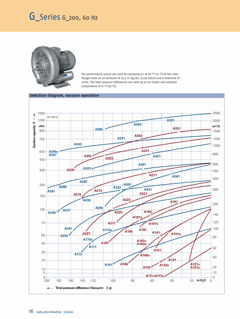
G_Series G_200, 60 Hz
Selection diagram, vacuum operation
The performance curves are valid for pumping air at 60 °F (15 °C) at the inlet
flanges with an air pressure of 29,9 in Hg abs. (1,013 mbar) and a tolerance of
±10%. The total pressure differences are valid up to an intake and ambient
temperature of 77 °F (25 °C).
uG_5011j
A385
1500
A351
A321
A383
A381
A341
A343
A345=A347
A281
A323
A287
A285
A283A263
A233
A261
A231
A235
A237A239
A265
A201
A203
A173s
A175s
A171
A173
A141
A353
A355
A331
A333
A335
A271
A273
A275 A221
A223
A225
A211
A227
A191
A193
A197s
A181s
A181A195
A197
A161 A151s
A151
A165s
A163=A163s
A165
A131
A133sA133
A111=A111s
A121=A121s
0200 180 160 140 120 100 80 60 40 20 0in H2O
Total pressure difference (Vacuum) ∆ p
Su
ctio
n c
ap
aci
ty V
cfm
010
20
40
60
80
100
120
150
200
300
400
500
600
800
1000
1200
1500
m3/h
2000
2500
1200
900
700
500
400
300
200
150
100
70
50
40
30
20
105

nash_elmo Industries G_Series 17
Curve no. Weightapprox.
lbs
Order no. Vacuum-reliefvalve2)
Items x type 2BX2...
Pressure-reliefvalve2)
Items x type 2BX2...
Soundpressurelevel1)
dB(A)
MotorRated
output voltage4) currenthp V A
Selection and ordering information for 60 Hz, 3AC, IP55
Selection and ordering information for 60 (50) Hz, 1AC, IP55
Details on voltages, footnotes etc. see page 83.� �
T
A111 0.3 220-275 B / 380-480 Y 2.0 B / 1.2 Y 2BH1 100-7A H 0 6 15 53 – –A121 0.4 220-275 B / 380-480 Y 1.74 B / 1.0 Y 2BH1 200-7A H 0 6 18 61 – –A131 0.4 220-275 B / 380-480 Y 2.0 B / 1.15 Y 2BH1 300-7A H 0 6 18 56 1 x 114/142 1 x 115/144A133 0.7 220-275 B / 380-480 Y 2.6 B / 1.5 Y 2BH1 300-7A H 1 6 22 56 1 x 114/142 1 x 115/144A141 1.1 220-275 B / 380-480 Y 3.75 B / 2.15 Y 2BH1 310-7H H 2 6 31 61 1 x 114/142 1 x 115/144A151 1.1 220-275 B / 380-480 Y 3.6 B / 2.1 Y 2BH1 490-7A H 1 6 31 64 – –A161 1.1 220-275 B / 380-480 Y 3.75 B / 2.15 Y 2BH1 400-7A H 0 6 29 64 1 x 114/142 1 x 115/144A163 1.3 220-275 B / 380-480 Y 4.0 B / 2.3 Y 2BH1 400-7A H 1 6 33 64 1 x 114/142 1 x 115/144A165 2 220-275 B / 380-480 Y 6.9 B / 4.0 Y 2BH1 400-7A H 2 6 35 64 1 x 114/142 1 x 115/144A171 2.8 220-275 B / 380-480 Y 7.6 B / 4.4 Y 2BH1 410-7H H 3 6 53 69 1 x 114/142 1 x 115/144A173 3.4 220-275 B / 380-480 Y 10.0 B / 5.8 Y 2BH1 410-7H H 4 6 60 69 1 x 114/142 1 x 115/144A181 2.3 220-275 B / 380-480 Y 7.6 B / 4.4 Y 2BH1 590-7A H 2 6 46 70 – –A191 1.3 220-275 B / 380-480 Y 4.0 B / 2.3 Y 2BH1 500-7A H 0 6 40 70 1 x 114/146 2 x 115/148A193 2 220-275 B / 380-480 Y 6.9 B / 4.0 Y 2BH1 500-7A H 1 6 44 70 1 x 114/146 1 x 115/148A195 2.8 220-275 B / 380-480 Y 7.6 B / 4.4 Y 2BH1 500-7A H 2 6 46 70 1 x 114/146 1 x 115/148A197 3.4 220-275 B / 380-480 Y 10.3 B / 6.0 Y 2BH1 500-7A H 3 6 55 70 1 x 114/146 1 x 115/148A201 4.6 220-275 B / 380-480 Y 12.6 B / 7.3 Y 2BH1 510-7H H 4 6 86 74 1 x 114/146 1 x 115/148A203 6.2 220-275 B / 380-480 Y 17.2 B / 9.9 Y 2BH1 510-7H H 5 6 43 74 1 x 114/146 1 x 115/148A211 4.6 220-275 B / 380-480 Y 12.6 B / 7.3 Y 2BH1 690-7A H 2 6 68 72 – –A221 2.8 220-275 B / 380-480 Y 8.8B / 5.1 Y 2BH1 600-7A H 0 6 57 72 1 x 114/146 2 x 115/148A223 3.4 220-275 B / 380-480 Y 10.3 B / 6.5 Y 2BH1 600-7A H 1 6 64 72 1 x 114/146 2 x 115/148A225 4.6 220-275 B / 380-480 Y 12.6 B / 7.3 Y 2BH1 600-7A H 2 6 75 72 1 x 114/146 1 x 115/148A227 6.2 220-275 B / 380-480 Y 16.4 B / 9.5 Y 2BH1 600-7A H 3 6 42 72 1 x 114/146 1 x 115/148A231 3.4 220-275 B / 380-480 Y 10.3 B / 6.0 Y 2BH1 610-7H H 1 6 93 76 2 x 114/146 2 x 115/148A233 4.6 220-275 B / 380-480 Y 12.6 B / 7.3 Y 2BH1 610-7H H 2 6 104 76 2 x 114/146 2 x 115/148A235 6.4 220-275 B / 380-480 Y 18 B / 10.4 Y 2BH1 610-7H H 3 6 53 76 1 x 114/146 2 x 115/148A237 8.5 220-275 B / 380-480 Y 23 B / 13.3 Y 2BH1 610-7H H 4 6 70 76 1 x 114/146 1 x 115/148A239 11.5 220-275 B / 380-480 Y 30 B / 17.3 Y 2BH1 610-7H H 5 6 77 76 1 x 114/146 1 x 115/148A261 6.2 220-275 B / 380-480 Y 16.4 B / 9.5 Y 2BH1 640-7G H 3 6 53 78 2 x 114/146 3 x 115/148A263 8.5 220-275 B / 380-480 Y 23 B / 13.3 Y 2BH1 640-7G H 4 6 73 78 2 x 114/146 3 x 115/148A265 11.5 220-275 B / 380-480 Y 30 B / 17.3 Y 2BH1 640-7G H 5 6 86 78 1 x 114/146 2 x 115/148A271 6.2 220-275 B / 380-480 Y 16.4 B / 9.5 Y 2BH1 800-7A H 0 6 112 74 2 x 114 2 x 115A273 8.5 220-275 B / 380-480 Y 23 B / 13.3 Y 2BH1 800-7A H 1 6 126 74 1 x 114 2 x 115A275 11.5 220-275 B / 380-480 Y 30 B / 17.3 Y 2BH1 800-7A H 2 6 128 74 1 x 114 1 x 115A281 8.5 220-275 B / 380-480 Y 23 B / 13.3 Y 2BH1 810-7H H 1 6 163 78 3 x 114 3 x 115A283 11.5 220-275 B / 380-480 Y 30 B / 17.3 Y 2BH1 810-7H H 2 6 169 78 2 x 114 2 x 115A285 16.9 220-275 B / 380-480 Y 50.2 B / 29 Y 2BH1 810-7H H 3 6 205 78 1 x 114 2 x 115A287 23.2 220-275 B / 380-480 Y 60 B / 34.5 Y 2BH1 810-7H H 4 6 221 78 1 x 114 1 x 115A321 11.5 220-275 B / 380-480 Y 30.8 B / 17.6 Y 2BH1 840-7J H 2 6 160 78 1 x 152 1 x 153A323 16.9 220-275 B / 380-480 Y 50.2 B / 29 Y 2BH1 840-7J H 3 6 200 78 3 x 114 1 x 151A331 13.1 220-275 B / 380-480 Y 33 B / 19,1 Y 2BH1 900-7A H 0 6 172 79 1 x 152 1 x 153A333 19.4 220-275 B / 380-480 Y 50 B / 29 Y 2BH1 900-7A H 1 6 191 79 3 x 114 1 x 151A335 28.6 220-275 B / 380-480 Y 68 B / 39 Y 2BH1 900-7A H 3 6 204 79 2 x 114 3 x 115A341 19.4 220-275 B / 380-480 Y 50 B / 29 Y 2BH1 910-7H H 1 6 265 84 1 x 152 1 x 153A343 25.5 220-275 B / 380-480 Y 63 B / 36.5 Y 2BH1 910-7H H 2 6 278 84 1 x 150 1 x 153A345 30.8 220-275 B / 380-480 Y 72 B / 42 Y 2BH1 910-7H H 3 6 295 84 3 x 114 1 x 151A347 38.9 220-275 B / 380-480 Y 90 B / 52 Y 2BH1 910-7H H 4 6 325 84 3 x 114 1 x 151A351 13.1 220-275 B / 380-480 Y 33 B / 19.1 Y 2BH1 930-7A H 0 6 174 80 1 x 152 1 x 153A353 19.4 220-275 B / 380-480 Y 50 B / 29 Y 2BH1 930-7A H 1 6 193 80 1 x 152 1 x 153A355 28.6 220-275 B / 380-480 Y 68 B / 39 Y 2BH1 930-7A H 3 6 206 80 1 x 150 1 x 151A381 23.5 220-275 B / 380-480 Y 63 B / 36.5 Y 2BH1 943-7G H 2 63) 270 84 1 x 154 1 x 155A383 30.8 220-275 B / 380-480 Y 72 B / 42 Y 2BH1 943-7G H 3 63) 300 84 1 x 152 1 x 155A385 38.9 220-275 B / 380-480 Y 90 B / 52 Y 2BH1 943-7G H 4 63) 330 84 1 x 152 1 x 153
A111s 0.3 115 / 230 / 5.2 / 2.6 2BH1 100-7A V 0 5 15 53 – –A121s 0.43 115 / 230 / 5.7 / 2.9 2BH1 200-7A V 0 5 18 61 – –A133s 0.6 115 / 230 6.0 / 3.0 2BH1 300-7A V 1 5 22 56 1 x 114/142 1 x 115/144A151s 0.83 115 / 10 / 2BH1 490-7A B 1 6 31 64 – –A163s 1.2 115 / 11.6 / 2BH1 400-7A B 1 6 33 64 1 x 114/142 1 x 115/144A165s 1.7 115 / 230 16.6 / 8.3 2BH1 400-7A V 2 5 35 64 1 x 114/142 1 x 115/144A173s 2.4 115 / 230 24 / 12 2BH1 410-7H V 4 5 53 69 1 x 114/142 1 x 115/144A181s 2.4 115 / 21.5 / 2BH1 590-7A B 2 6 46 70 – –A197s 2.4 115 / 230 24 / 12.0 2BH1 500-7A V 3 5 49 70 1 x 114/146 1 x 115/148

1471
1177
883
706
589
471
353
294
235
177
118
88
71
59
47
35
24
1260
0 20 40 8060 100 120 140 160 240 320in H2O
Total pressure difference (Vacuum) ∆ p
Su
ctio
n c
ap
aci
ty V
cfm
01020
40
60
80
100
120
150
200
300
400
500
600
800
1000
1200
1500
m3/h
2000
2500
21
180 200 280
uG_5012kA381
A383 A385
A341A343
A345
A347
A323
A283
A281
A285
A287
A237
A235
A239
A265
A321
A261
A263A231
A233
A173s
A201
A203A171
A175s
A173
A141
A111=A111s
A133
A121=A121s A133s
A131
A151
A151s
A165
A165s
A163s
A163
A161 A181
A197
A181s
A191
A193A197s
A195A211
A227
A225
A223A221 A275
A273A271
A331
A333 A355
A353
A351
A335
nash_elmo Industries G_Series 18
G_Series G_200, 60 Hz
Selection diagram, compressor operation
The performance curves are valid for pumping air at 60 °F (15 °C) at the inlet flanges with an air
pressure of 29,9 in Hg abs. (1,013 mbar) and a tolerance of ±10%. The total pressure differences
are valid up to an intake and ambient temperature of 77 °F (25 °C).

A221
21
A381
A321
A281
A261
A231A233
A235
A237
A239
A263
A265
A201
A171
A173
A175s
A173s
A141
A203
A283
A285
A287
A323
A351
A353
A331
A271
A273
A275
A333
A335
A355
A383A385
A341
A343A345
A347
A223A225
A211
A227
A191
A161
A151
A131
A111=A111s
A121=
A121s
A133
A163
A165
A193
A195
A197
A197sA181s
A151sA163s
A133s
A165s
2500
2000
1500
1200
1000
800
600
500
400
300
200
150
120
100
80
60
40
20
100
m3/h
0 100 200 300 400 500 600 800mbar
40
30
20
15
10987
6
5
4
3
2
1,5
1
0,8
0,5
0,2
0
m3/min
PV-5012k
A181
nash_elmo Industries G_Series 18nash_elmo Industries G_Series 17
G_Series G_200, 60 Hz
Curve no. Weightapprox.
kg
Order no.
•• Available
ex stock
Vacuum-reliefvalve2)
Items x type 2BX2...
Pressure-reliefvalve2)
Items x type 2BX2...
Sound-pressurelevel1)
dB(A)
MotorRated-
output voltage4) currentkW V A
Selection and ordering information for 60 Hz, 3AC, IP55
Selection and ordering information for 60 (50) Hz, 1AC, IP55
Selection diagram, compressor operation
The performance curves are valid for pumping air at 15 °C at the inlet
flanges with an air pressure of 1,013 mbar and a tolerance of ±10%.
The total pressure differences are valid up to an intake and ambient
temperature of 25 °C.
Details on voltages, footnotes etc. see page 82.▲ ▲
A111 0.23 220-275 B / 380-480 Y 2.0 B / 1.2 Y •2BH1 100-7A H 0 6 7 53 – –A121 0.29 220-275 B / 380-480 Y 1.74 B / 1.0 Y •2BH1 200-7A H 0 6 8 61 – –A131 0.29 220-275 B / 380-480 Y 2.0 B / 1.15 Y •2BH1 300-7A H 0 6 8 56 1 x 114/142 1 x 115/144A133 0.5 220-275 B / 380-480 Y 2.6 B / 1.5 Y •2BH1 300-7A H 1 6 10 56 1 x 114/142 1 x 115/144A141 0.83 220-275 B / 380-480 Y 3.75 B / 2.15 Y 2BH1 310-7H H 2 6 14 61 1 x 114/142 1 x 115/144A151 0.85 220-275 B / 380-480 Y 3.6 B / 2.1 Y •2BH1 490-7A H 1 6 14 64 – –A161 0.83 220-275 B / 380-480 Y 3.75 B / 2.15 Y •2BH1 400-7A H 0 6 13 64 1 x 114/142 1 x 115/144A163 0.95 220-275 B / 380-480 Y 4.0 B / 2.3 Y •2BH1 400-7A H 1 6 15 64 1 x 114/142 1 x 115/144A165 1.5 220-275 B / 380-480 Y 6.9 B / 4.0 Y •2BH1 400-7A H 2 6 16 64 1 x 114/142 1 x 115/144A171 2.05 220-275 B / 380-480 Y 7.6 B / 4.4 Y •2BH1 410-7H H 3 6 24 69 1 x 114/142 1 x 115/144A173 2.55 220-275 B / 380-480 Y 10.0 B / 5.8 Y •2BH1 410-7H H 4 6 27 69 1 x 114/142 1 x 115/144A181 1.7 220-275 B / 380-480 Y 7.6 B / 4.4 Y •2BH1 590-7A H 2 6 21 70 – –A191 0.95 220-275 B / 380-480 Y 4.0 B / 2.3 Y •2BH1 500-7A H 0 6 18 70 1 x 114/146 2 x 115/148A193 1.5 220-275 B / 380-480 Y 6.9 B / 4.0 Y •2BH1 500-7A H 1 6 20 70 1 x 114/146 1 x 115/148A195 2.05 220-275 B / 380-480 Y 7.6 B / 4.4 Y •2BH1 500-7A H 2 6 21 70 1 x 114/146 1 x 115/148A197 2.55 220-275 B / 380-480 Y 10.3 B / 6.0 Y •2BH1 500-7A H 3 6 25 70 1 x 114/146 1 x 115/148A201 3.45 220-275 B / 380-480 Y 12.6 B / 7.3 Y •2BH1 510-7H H 4 6 39 74 1 x 114/146 1 x 115/148A203 4.6 380-480 B 9.9 B •2BH1 510-7H H 5 7 43 74 1 x 114/146 1 x 115/148A211 3.45 220-275 B / 380-480 Y 12.6 B / 7.3 Y •2BH1 690-7A H 2 6 31 72 – –A221 2.05 220-275 B / 380-480 Y 8.8B / 5.1 Y •2BH1 600-7A H 0 6 26 72 1 x 114/146 2 x 115/148A223 2.55 220-275 B / 380-480 Y 10.3 B / 6.5 Y •2BH1 600-7A H 1 6 29 72 1 x 114/146 2 x 115/148A225 3.45 220-275 B / 380-480 Y 12.6 B / 7.3 Y •2BH1 600-7A H 2 6 34 72 1 x 114/146 1 x 115/148A227 4.6 380-480 B 9.5 B •2BH1 600-7A H 3 7 42 72 1 x 114/146 1 x 115/148A231 2.55 220-275 B / 380-480 Y 10.3 B / 6.0 Y •2BH1 610-7H H 1 6 42 76 2 x 114/146 2 x 115/148A233 3.45 220-275 B / 380-480 Y 12.6 B / 7.3 Y •2BH1 610-7H H 2 6 47 76 2 x 114/146 2 x 115/148A235 4.8 380-480 B 10.4 B •2BH1 610-7H H 3 7 53 76 1 x 114/146 2 x 115/148A237 6.3 380-480 B 13.3 B •2BH1 610-7H H 4 7 70 76 1 x 114/146 1 x 115/148A239 8.6 380-480 B 17.3 B •2BH1 610-7H H 5 7 77 76 1 x 114/146 1 x 115/148A261 4.6 380-480 B 9.5 B •2BH1 640-7G H 3 7 53 78 2 x 114/146 3 x 115/148A263 6.3 380-480 B 13.3 B •2BH1 640-7G H 4 7 73 78 2 x 114/146 3 x 115/148A265 8.6 380-480 B 17.3 B 2BH1 640-7G H 5 7 86 78 1 x 114/146 2 x 115/148A271 4.6 380-480 B 9.5 B 2BH1 800-7A H 0 7 112 74 2 x 114 2 x 115A273 6.3 380-480 B 13.3 B •2BH1 800-7A H 1 7 126 74 1 x 114 2 x 115A275 8.6 380-480 B 17.3 B 2BH1 800-7A H 2 7 128 74 1 x 114 1 x 115A281 6.3 380-480 B 13.3 B •2BH1 810-7H H 1 7 163 78 3 x 114 3 x 115A283 8.6 380-480 B 17.3 B •2BH1 810-7H H 2 7 169 78 2 x 114 2 x 115A285 12.6 380-480 B 29 B •2BH1 810-7H H 3 7 205 78 1 x 114 2 x 115A287 17.3 380-480 B 34.5 B 2BH1 810-7H H 4 7 221 78 1 x 114 1 x 115A321 8.6 380-480 B 17.6 B •2BH1 840-7 J H 2 7 160 78 1 x 152 1 x 153A323 12.6 380-480 B 29 B •2BH1 840-7 J H 3 7 200 78 3 x 114 1 x 151A331 9.8 380-480 B 19.1 B •2BH1 900-7A H 0 7 172 79 1 x 152 1 x 153A333 14.5 380-480 B 29 B •2BH1 900-7A H 1 7 191 79 3 x 114 1 x 151A335 21.3 380-480 B 39 B •2BH1 900-7A H 3 7 204 79 2 x 114 3 x 115A341 14.5 380-480 B 29 B 2BH1 910-7H H 1 7 265 84 1 x 152 1 x 153A343 19 380-480 B 36.5 B •2BH1 910-7H H 2 7 278 84 1 x 150 1 x 153A345 23 380-480 B 42 B •2BH1 910-7H H 3 7 295 84 3 x 114 1 x 151A347 29 380-480 B 52 B 2BH1 910-7H H 4 7 325 84 3 x 114 1 x 151A351 9.8 380-480 B 18.2 B 2BH1 930-7A H 0 7 174 80 1 x 152 1 x 153A353 14.5 380-480 B 29 B 2BH1 930-7A H 1 7 193 80 1 x 152 1 x 153A355 21.3 380-480 B 39 B 2BH1 930-7A H 3 7 206 80 1 x 150 1 x 151A381 17.5 380-480 B 36.5 B 2BH1 943-7G H 2 73) 270 84 1 x 154 1 x 155A383 23 380-480 B 42 B •2BH1 943-7G H 3 73) 300 84 1 x 152 1 x 155A385 29 380-480 B 52 B 2BH1 943-7G H 4 73) 330 84 1 x 152 1 x 153
A111s 0.23 115 / 230 / 5.2 / 2.6 2BH1 100-7A V 0 5 7 53 – –A121s 0.32 115 / 230 / 5.7 / 2.9 2BH1 200-7A V 0 5 8 61 – –A133s 0.45 115 / 230 6.0 / 3.0 •2BH1 300-7A V 1 5 10 56 1 x 114/142 1 x 115/144A151s 0.62 115 / 10 / 2BH1 490-7A B 1 6 14 64 – –A163s 0.9 115 / 11.6 / 2BH1 400-7A B 1 6 15 64 1 x 114/142 1 x 115/144A165s 1.3 115 / 230 16.6 / 8.3 •2BH1 400-7A V 2 5 16 64 1 x 114/142 1 x 115/144A173s 1.75 115 / 230 24 / 12 2BH1 410-7H V 4 5 24 69 1 x 114/142 1 x 115/144A181s 1.75 115 / 21.5 / 2BH1 590-7A B 2 6 21 70 – –A197s 1.75 115 / 230 24 / 12.0 2BH1 500-7A V 3 5 22 70 1 x 114/146 1 x 115/148
Su
cti
on
cap
acit
y
Total pressure difference (Pressure)
Please open this page for selection diagram.
▼

20 nash_elmo Industries G_Series
Order no.
Gas ring compressor Gas ring compressorwith integrated FC for external FC external FC
Rated per-formance
P (in hp)
Speed range
min-1
G_Series G_200e with frequency converter
The G_200 pumps and compressors with integra-
ted frequency converter (FC) are supplied with a
standard speed of 5,000 min-1. A reduction in the
speed and thus adaptation to the required duty
point is possible
1. manually: by adjusting the setting at the
potentiometer
2. automatically: by specifying the target value
via the analogue input (0 ... 10 V, 0 .. 20 mA)
3. automatically: via the digital input
The range meets the EMC guidelines because of
the radio interference suppression filter (class A)
that is installed as standard.
Standard protection features:
■ Over-voltage protection
■ Short-circuit protection
■ Overheating protection of converter
■ PTC thermistor for integrated converter,
optional for external converter
A142e 2.0 2,200 ... 5,000 2BH1 310-7HN21 2BH1 310-7HH26 2FC4 152-2NE00
A162e 3.0 2,200 ... 5,000 2BH1 400-7AN21 2BH1 400-7AH26 2FC4 222-2NE00
vacuum operation compressor operation
vacuum operation compressor operation
Selection and ordering information for 3 AC, 45...65 Hz, 360-550 V, IP55
Curve no.
The performance curves are valid
for pumping air at 60 °F (15 °C) at
the inlet flanges with an air pres-
sure of 29,9 in Hg abs. (1,013 mbar)
and a tolerance of ±10%. The total
pressure differences are valid up to
an intake and ambient temperature
of 77 °F (25 °C).
Selection diagram 2BH1 310-...
Selection diagram 2BH1 400-...
90
80
70
60
50
40
30
20
10
0
100 80 60 40 20 0 20 40 60 80 100
A142e
uG_6101
Su
cti
on
cap
acit
y V
cfm
(Vacuum) Total pressure difference �p (Pressure)
in H22O
150
120
90
60
30
0
120 100 80 60 40 20 0 20 40 60 80 100 120
A162e
uG_6102
Su
cti
on
cap
acit
y V
cfm
(Vacuum) Total pressure difference �p (Pressure)
in H22O

nash_elmo Industries G_Series 21
vacuum operation compressor operation
vacuum operation compressor operation
Curve no. Rated per-formance
P (in hp)
Speed range
min-1
A174e 5.4 2,200 ... 5,000 2BH1 410-7HN41 2BH1 410-7HH46 2FC4 402-2NE00
A193e 5.4 2,200 ... 5,000 2BH1 500-7AN31 2BH1 500-7AH36 2FC4 402-2NE00
A205e 10 2,200 ... 5,000 2BH1 510-7HN51 2BH1 510-7HH56 2FC4 752-2NE00
vacuum operation compressor operation
Selection and ordering information for 3 AC, 45...65 Hz, 360-550 V, IP55
The performance curves are valid
for pumping air at 60 °F (15 °C) at
the inlet flanges with an air pres-
sure of 29,9 in Hg abs. (1,013 mbar)
and a tolerance of ±10%. The total
pressure differences are valid up to
an intake and ambient temperature
of 77 °F (25 °C).
Selection diagram 2BH1 410-...
Selection diagram 2BH1 500-...
Selection diagram 2BH1 510-...
150
125
100
75
50
25
0
180 160 140 120 100 80 60 40 20 0 40 60 80 100 120 140 160 180
A174e
uG_6103
Su
cti
on
cap
acit
y V
cfm
in H22O
250
200
150
100
50
0
140 120 100 80 60 40 20 0 40 60 80 100 120 140
A193e
uG_6104
Su
cti
on
cap
acit
y V
cfm
(Vacuum) Total pressure difference �p (Pressure)
in H22O
250
200
150
100
50
0
200 160 120 80 40 0 40 80 120 160 200
A205e
uG_6105
Su
cti
on
cap
acit
y V
cfm
(Vacuum) Total pressure difference �p (Pressure)
in H22O
Order no.
Gas ring compressor Gas ring compressorwith integrated FC for external FC external FC

22 nash_elmo Industries G_Series
G_Series G_200e with frequency converter
Order no.
Gas ring compressor Gas ring compressorwith integrated FC for external FC external FC
A223e 10.1 2,200 ... 5,000 2BH1 600-7AN31 2BH1 600-7AH36 2FC4 752-2NE00
A233e 10.1 2,200 ... 5,000 2BH1 610-7HN31 2BH1 610-7HH36 2FC4 752-2NE00
A235e 14.8 2,200 ... 5,000 – 2BH1 610-7HH56 2FC4 113-2NE00
A264e 14.8 2,200 ... 4,200 – 2BH1 640-7GH46 2FC4 113-2NE00
A265e 20.1 2,200 ... 5,000 – 2BH1 640-7GH56 2FC4 153-2NE00
Rated per-formance
P (in hp)
Curve no. Speed range
min-1
Selection and ordering information for 3 AC, 45...65 Hz, 360-550 V, IP55
vacuum operation compressor operation
vacuum operation compressor operation
vacuum operation compressor operation
Selection diagram 2BH1 600-...
Selection diagrams 2BH1 610-...
Selection diagrams 2BH1 640-...
300
250
200
150
100
50
0
140 120 100 80 60 40 20 0 40 60 80 100 120 140
A223e
uG_6106
Su
cti
on
cap
acit
y V
cfm
(Vacuum) Total pressure difference �p (Pressure)
in H22O
350
300
250
200
150
100
50
0
280 240 200 160 120 80 40 0 80 120 160 200 240 280
A233eA235e
uG_6107
Su
cti
on
cap
acit
y V
cfm
(Vacuum) Total pressure difference �p (Pressure)
in H22O
500
400
300
200
100
0
140 120 100 80 60 40 20 0 40 60 80 100 120 140
A264eA265e
uG_6108
Su
cti
on
cap
acit
y V
cfm
(Vacuum) Total pressure difference �p (Pressure)
in H22O
The performance curves are valid
for pumping air at 60 °F (15 °C) at
the inlet flanges with an air pres-
sure of 29,9 in Hg abs. (1,013 mbar)
and a tolerance of ±10%. The total
pressure differences are valid up to
an intake and ambient temperature
of 77 °F (25 °C).

A270e 10 2,200 ... 5,000 2BH1 800-7AN01 2BH1 800-7AH06 2FC4 752-2NE00
A272e 20.1 2,200 ... 5,000 – 2BH1 800-7AH26 2FC4 153-2NE00
A282e 20.1 2,200 ... 5,000 – 2BH1 810-7HH26 2FC4 153-2NE00
A284e 40.2 2,200 ... 5,000 – 2BH1 810-7HH46 2FC4 303-2NE00
A323e 29.5 2,200 ... 5,000 – 2BH1 840-7JH36 2FC4 223-2NE00
Order no.
Gas ring compressor Gas ring compressorwith integrated FC for external FC external FC
Speed range
min-1
Rated per-formance
P (in hp)
Curve no.
Selection and ordering information for 3 AC, 45...65 Hz, 360-550 V, IP55
nash_elmo Industries G_Series 23
vacuum operation compressor operation
vacuum operation compressor operation
vacuum operation compressor operation
Selection diagrams 2BH1 800-...
Selection diagrams 2BH1 810-...
Selection diagram 2BH1 840-...
600
540
480
420
360
300
240
180
120
60
0
180 160 140 120 100 80 60 40 20 0 40 60 80 100 120 140 160 180
A270eA272e
uG_6109
Su
cti
on
cap
acit
y V
cfm
(Vacuum) Total pressure difference �p (Pressure)
in H22O
500
400
300
200
100
0
320 280 240 200 160 120 80 40 0 80 120 160 200 240 280 320
uG_6110
A282eA284e
Su
cti
on
cap
acit
y V
cfm
(Vacuum) Total pressure difference �p (Pressure)
in H22O
900
800
700
600
500
400
300
200
100
0
120 100 80 60 40 20 0 20 40 60 80 100 120
A323e
uG_6111
Su
cti
on
cap
acit
y V
cfm
(Vacuum) Total pressure difference �p (Pressure)
in H22O
The performance curves are valid
for pumping air at 60 °F (15 °C) at
the inlet flanges with an air pres-
sure of 29,9 in Hg abs. (1,013 mbar)
and a tolerance of ±10%. The total
pressure differences are valid up to
an intake and ambient temperature
of 77 °F (25 °C).

24 nash_elmo Industries G_Series
G_Series G_200e with frequency converter
A330e 20.1 2,200 ... 4,200 – 2BH1 900-7AH06 2FC4 153-2NE00
A333e 40.2 2,200 ... 4,200 – 2BH1 900-7AH36 2FC4 303-2NE00
A341e 29.5 2,200 ... 4,200 – 2BH1 910-7HH16 2FC4 223-2NE00
A344e 60.3 2,200 ... 4,200 – 2BH1 910-7HH46 2FC4 453-2NE00
A382e 29.5 2,200 ... 3,600 – 2BH1 943-7GH26 2FC4 223-2NE00
A384e 60.3 2,200 ... 4,200 – 2BH1 943-7GH46 2FC4 453-2NE00
Speed range
min-1
Order no.
Gas ring compressor Gas ring compressorwith integrated FC for external FC external FC
Rated per-formance
P (in hp)
Curve no.
Selection and ordering information for 3 AC, 45...65 Hz, 360-550 V, IP55
vacuum operation compressor operation
vacuum operation compressor operation
vacuum operation compressor operation
Selection diagrams 2BH1 900-...
Selection diagrams 2BH1 910-...
Selection diagrams 2BH1 943-...
900
800
700
600
500
400
300
200
100
0
200 160 120 80 40 0 40 80 120 160 200
uG_6112
A330eA333e
Su
cti
on
cap
acit
y V
cfm
(Vacuum) Total pressure difference �p (Pressure)
in H22O
900
800
700
600
500
400
300
200
100
0
280 240 200 160 120 80 40 0 80 120 160 200 240 280
uG_6113
A341eA344e
Su
cti
on
cap
acit
y V
cfm
(Vacuum) Total pressure difference �p (Pressure)
in H22O
1800
1500
1200
900
600
300
0
140 120 100 80 60 40 20 0 40 60 80 100 120 140
A382eA384e
uG_6114
Su
cti
on
cap
acit
y V
cfm
(Vacuum) Total pressure difference �p (Pressure)
in H22O
The performance curves are valid
for pumping air at 60 °F (15 °C) at
the inlet flanges with an air pres-
sure of 29,9 in Hg abs. (1,013 mbar)
and a tolerance of ±10%. The total
pressure differences are valid up to
an intake and ambient temperature
of 77 °F (25 °C).

nash_elmo Industries G_Series 25
Notes
G_400
G_400e with integrated or external
frequency converter
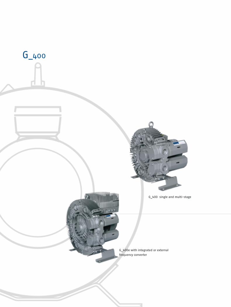
G_400 single and multi-stage

G_400Unsurpassed at highest differential pressure
Our revolutionary G_400 blowers can create pressure differences of up to
400 inch H2O — more than any other gas ring pump! So far, the systems used
to reach these differential pressure ranges were much louder and larger — or
subject to wear. Now the advantages of wear-free operation coupled with a
low noise level can also be used in the most demanding applications.
The G_400 vacuum pumps and compressors can work up to 20,000 hours
without maintenance down time.
These specialist machines have proven their reliability under the harshest of
conditions. Their noise level was already impressively low, but our engineers
and designers were able to make them even more quiet.
Selection diagrams and tables for G_400, pages 28-29
vacuum and compressor mode, 50 and 60 Hz
G_400e pumps and compressors with speed control pages 30-33
and frequency converter
Details on voltages, footnotes etc. see page 83

28 nash_elmo Industries G_Series
G_Series G_400, 50/60 Hz
Vacuum-compressor selection diagram 50 Hz
Vacuum-compressor selection diagram 60 Hz
Total pressure difference ∆ p(Vacuum) (Pressure)
100
90
80
70
60
50
40
30
20
10
cfm
320 280 240 200 160 120 80 40 40 80 120 160 200 240 280 320 360 400 440in H2O
uG_5317h
Su
cti
on
cap
acit
y V
B282
B272
B270
B240
B244
B212
B210
B180
B152
B150sB150
B182=B182s
B260
B262B230
B200s
B140=B140s B172=B172s
B200 B232
B282
B270=B272
B150=B152=B150s
B240
B244B180s
B210
B212
B180=B182
B230=B232
B200=B200s B172
B142=B140s
B170=B172s
B260=B262
B170
Total pressure difference ∆ p(Vacuum) (Pressure)
B213
B211
B181s
B151s
B173B153
B181
B263
B231
B263
B261
B201=
B201s
B271
B283
B273B241
B245
B213
B211
B153B151s
B183
B181s
B141s
B245
B173s
B141
B233
B201
B261
B183B151
B141s
B151
uG_5318g120
110
100
90
80
70
60
50
40
30
20
10
0320 280 240 200 160 120 80 40 40 80 120 160 200 240 280 320 360 400 440in H2O
cfm
Su
cti
on
cap
acit
y V
B283
B271=
B273
B241
B201s
B171
B141
B173s
B173
B231 B171
B181
B233
The performance curves are valid for pumping air at 60 °F (15 °C) at the inlet flanges with
an air pressure of 29,9 in Hg abs. (1,013 mbar) and a tolerance of ±10%. The total pressure
differences are valid up to an intake and ambient temperature of 77 °F (25 °C).

nash_elmo Industries G_Series 29
Curve no. Weightapprox.
lbs
Order no. Vacuum-reliefvalve2)
Items x Typ 2BX2...
Pressure-reliefvalve2)
Items x Typ2BX2...
Soundpressurelevel1)
dB(A)
MotorRated
output voltage4) currenthp V A
Selection and ordering information for 50 Hz, 3AC, IP55
Selection and ordering information for 60 Hz, 3AC, IP 55
B140 0.8 200-240 B / 345-415 Y 2.8 B / 1.6 Y 2BH7 210-0A H 1 6-7 35 57 1 x 110/141 1 x 111/143B150 1.1 200-240 B / 345-415 Y 4 B / 2.3 Y 2BH7 220-0A H 2 6-7 53 58 1 x 110/141 1 x 111/143B152 2 200-240 B / 345-415 Y 7.5 B / 4.3 Y 2BH7 220-0A H 5 6-7 62 58 1 x 110/141 1 x 111/143B170 0.7 200-240 B / 345-415 Y 2.8 B / 1.6 Y 2BH7 310-0A H 1 6-7 35 57 1 x 110/141 1 x 111/143B172 1.1 200-240 B / 345-415 Y 4 B / 2.3 Y 2BH7 310-0A H 2 6-7 37 57 1 x 110/141 1 x 111/143B180 1.5 200-240 B / 345-415 Y 5.4 B / 3.1 Y 2BH7 320-0A H 4 6-7 64 59 1 x 110/141 1 x 111/143B182 2 200-240 B / 345-415 Y 7.5 B / 4.3 Y 2BH7 320-0A H 5 6-7 66 59 1 x 110/141 1 x 111/143B200 1.5 200-240 B / 345-415 Y 5.4 B / 3.1 Y 2BH7 410-0A H 1 6-7 51 58 1 x 110/141 1 x 111/143B210 2 200-240 B / 345-415 Y 7.5 B / 4.3 Y 2BH7 420-0A H 2 6-7 73 61 1 x 110/141 1 x 111/143B212 4.4 200-240 B / 345-415 Y 13 B / 7.5 Y 2BH7 420-0A H 5 6-7 86 61 1 x 110/141 1 x 111/143B230 2 200-240 B / 345-415 Y 7.5 B / 4.3 Y 2BH7 510-0A H 1 6-8 57 64 1 x 110/141 1 x 111/143B232 3 200-240 B / 345-415 Y 11.4 B / 6.6 Y 2BH7 510-0A H 2 6-8 64 64 1 x 110/141 1 x 111/143B240 3 200-240 B / 345-415 Y 11.4 B / 6.6 Y 2BH7 520-0A H 2 6-8 88 64 1 x 110/141 1 x 111/143B244 5.4 200-240 B / 345-415 Y 15.5 B / 9 Y 2BH7 520-0A H 7 6-8 51 65 1 x 110/141 1 x 111/143B260 3 200-240 B / 345-415 Y 11.4 B / 6.6 Y 2BH7 610-0A H 1 6-8 71 65 1 x 110/141 1 x 111/143B262 4.4 200-240 B / 345-415 Y 13 B / 7.5 Y 2BH7 610-0A H 3 6-8 77 65 1 x 110/141 1 x 111/143B270 4.4 200-240 B / 345-415 Y 13 B / 7.5 Y 2BH7 620-0A H 3 6-8 106 67 1 x 110/141 1 x 111/143B272 7.6 200-240 B / 345-415 Y 21.5 B / 12.5 Y 2BH7 620-0A H 5 6-8 65 68 1 x 110/141 1 x 111/143B282 10.1 200-240 B / 345-415 Y 27.5 B / 16 Y 2BH7 630-0A H 6 6-8 86 72 1 x 110/141 1 x 111/143
B141 0.8 220-275 B / 380-480 Y 3 B / 1.7 Y 2BH7 210-0A H 1 6-7 35 62 1 x 114/142 1 x 115/144B151 1.3 220-275 B / 380-480 Y 4 B / 2.3 Y 2BH7 220-0A H 2 6-7 53 62 1 x 114/142 1 x 115/144B153 2.4 220-275 B / 380-480 Y 7.6 B / 4.4 Y 2BH7 220-0A H 5 6-7 62 62 1 x 114/142 1 x 115/144B171 0.8 220-275 B / 380-480 Y 3 B / 1.7 Y 2BH7 310-0A H 1 6-7 35 62 1 x 114/142 1 x 115/144B173 1.3 220-275 B / 380-480 Y 4 B / 2.3 Y 2BH7 310-0A H 2 6-7 37 62 1 x 114/142 1 x 115/144B181 1.7 220-275 B / 380-480 Y 5.4 B / 3.1 Y 2BH7 320-0A H 4 6-7 64 63 1 x 114/142 1 x 115/144B183 2.4 220-275 B / 380-480 Y 7.6 B / 4.4 Y 2BH7 320-0A H 5 6-7 66 63 1 x 114/142 1 x 115/144B201 1.7 220-275 B / 380-480 Y 5.4 B / 3.1 Y 2BH7 410-0A H 1 6-7 51 62 1 x 114/142 1 x 115/144B211 2.4 220-275 B / 380-480 Y 7.6 B / 4.4 Y 2BH7 420-0A H 2 6-7 73 66 1 x 114/142 1 x 115/144B213 5.1 220-275 B / 380-480 Y 13.8 B / 8 Y 2BH7 420-0A H 5 6-7 86 66 1 x 114/142 1 x 115/144B231 2.4 220-275 B / 380-480 Y 7.6 B / 4.4 Y 2BH7 510-0A H 1 6-8 57 68 1 x 114/142 1 x 115/144B233 3.4 220-275 B / 380-480 Y 11.2 B / 6.5 Y 2BH7 510-0A H 2 6-8 64 68 1 x 114/142 1 x 115/144B241 3.4 220-275 B / 380-480 Y 11.2 B / 6.5 Y 2BH7 520-0A H 2 6-8 88 70 1 x 114/142 1 x 115/144B245 6.2 220-275 B / 380-480 Y 16.5 B / 9.5 Y 2BH7 520-0A H 7 6-8 51 71 1 x 114/142 1 x 115/144B261 3.4 220-275 B / 380-480 Y 11.2 B / 6.5 Y 2BH7 610-0A H 1 6-8 71 71 1 x 114/142 1 x 115/144B263 5.1 220-275 B / 380-480 Y 14.2 B / 8.2 Y 2BH7 610-0A H 3 6-8 77 71 1 x 114/142 1 x 115/144B271 5.1 220-275 B / 380-480 Y 14.2 B / 8.2 Y 2BH7 620-0A H 3 6-8 106 71 1 x 114/142 1 x 115/144B273 8.9 220-275 B / 380-480 Y 21 B / 12 Y 2BH7 620-0A H 5 6-8 65 72 1 x 114/142 1 x 115/144B283 11.5 220-275 B / 380-480 Y 27.5 B / 16 Y 2BH7 630-0A H 6 6-8 86 76 1 x 114/142 1 x 115/144
B140s 0.7 115 / 230 13 / 3.1 2BH7 210-0A V 7 5-7 40 57B150s 2 115 / 230 19.4 / 9.7 2BH7 220-0A V 7 5-7 66 58B172s 1.3 115 / 230 15.2 / 7.6 2BH7 310-0A V 7 5-7 40 57B180s 2 115 / 230 19.4 / 9.7 2BH7 320-0A V 7 5-7 71 59B200s 1.5 115 / 230 16.0 / 8.0 2BH7 410-0A V 4 5-7 51 58
B141s 0.8 115 / 230 14.2 / 7.1 2BH7 210-0A V 7 5-7 40 62B151s 2.4 115 / 230 20.6 / 10.3 2BH7 220-0A V 7 5-7 66 62B173s 1.5 115 / 230 18 / 9 2BH7 310-0A V 7 5-7 40 62B181s 2.4 115 / 230 20.6 / 10.3 2BH7 320-0A V 7 5-7 71 63B201s 1.7 115 / 230/ 20 / 10 2BH7 410-0A V 4 5-7 51 62
Selection and ordering information for 50 Hz, 1AC, IP 55
Selection and ordering information for 60 Hz, 1AC, IP 55
Details on voltages, footnotes etc. see page 83.� �

30 nash_elmo Industries G_Series
vacuum operation compressor operation
vacuum operation compressor operation
Selection diagrams 2BH7 210-...
50
40
30
20
10
0
280 240 200 160 120 80 40 0 80 120 160 200 240 280
B141eB145e
uG_6130
Su
cti
on
cap
acit
y V
cfm
(Vacuum) Total pressure difference �p (Pressure)
in H22O
50
40
30
20
10
0
320 280 240 200 160 120 80 40 0 80 120 160 200 240 280 320
A155e
uG_6131
Su
cti
on
cap
acit
y V
cfm
(Vacuum) Total pressure difference �p (Pressure)
in H22O
G_Series G_400e with frequency converter
Order no.
Gas ring compressor Gas ring compressorwith integrated FC for external FC external FC
Rated per-formance
P (in hp)
Speed range
min-1
B141e 2 2,200 ... 5,000 2BH7 210-0AN11-7 2BH7 210-0AH16-7 2FC4 152-2NE00 74B145e 4 2,200 ... 5,000 2BH7 210-0AN51-7 2BH7 210-0AH56-7 2FC4 302-2NE00 74B155e 4 2,200 ... 5,000 2BH7 220-0AN51-7 2BH7 220-0AH56-7 2FC4 302-2NE00 74
Sound-pressurelevel1)
dB(A)
Curve no.
Selection and ordering information for 3 AC, 45....65 Hz, 360-550 V, IP55
The performance curves are valid
for pumping air at 60 °F (15 °C) at
the inlet flanges with an air pres-
sure of 29,9 in Hg abs. (1,013 mbar)
and a tolerance of ±10%. The total
pressure differences are valid up to
an intake and ambient temperature
of 77 °F (25 °C).
Selection diagram 2BH7 220-...
The G_400 pumps and compressors with integrated
frequency converter (FC) are supplied with a stan-
dard speed of 5,000 min-1. A reduction in the
speed and thus adaptation to the required duty
point is possible
1. manually: by adjusting the setting at the
potentiometer
2. automatically: by specifying the target value
via the analogue input (0 ... 10 V, 0 .. 20 mA)
3. automatically: via the digital input
The range meets the EMC guidelines because of the
radio interference suppression filter (class A) that is
installed as standard.
Standard protection features:
■ Over-voltage protection
■ Short-circuit protection
■ Overheating protection of converter
■ PTC thermistor for integrated converter,
optional for external converter

nash_elmo Industries G_Series 31
B172e 2 2,200 ... 5,000 2BH7 310-0AN21-7 2BH7 310-0AH26-7 2FC4 152-2NE00 76B176e 5.4 2,200 ... 5,000 2BH7 310-0AN61-7 2BH7 310-0AH66-7 2FC4 402-2NE00 76B185e 4 2,200 ... 5,000 2BH7 320-0AN51-7 2BH7 320-0AH56-7 2FC4 302-2NE00 76B188e 7.4 2,200 ... 5,000 2BH7 320-0AN81-7 2BH7 320-0AH86-7 2FC4 552-2NE00 76B201e 3 2,200 ... 5,000 2BH7 410-0AN11-7 2BH7 410-0AH16-7 2FC4 222-2NE00 76B205e 7.4 2,200 ... 5,000 2BH7 410-0AN51-7 2BH7 410-0AH56-7 2FC4 552-2NE00 76
Selection and ordering information for 3 AC, 45...65 Hz, 360-550 V, IP55
The performance curves are valid
for pumping air at 60 °F (15 °C) at
the inlet flanges with an air pres-
sure of 29,9 in Hg abs. (1,013 mbar)
and a tolerance of ±10%. The total
pressure differences are valid up to
an intake and ambient temperature
of 77 °F (25 °C).
Order no.
Gas ring compressor Gas ring compressorwith integrated FC for external FC external FC
Rated per-formance
P (in hp)
Speed range
min-1
Sound-pressurelevel1)
dB(A)
Curve no.
vacuum operation compressor operation
vacuum operation compressor operation
vacuum operation compressor operation
Selection diagrams 2BH7 310-...
Selection diagrams 2BH7 320-...
Selection diagrams 2BH7 410-...
70
60
50
40
30
20
10
0
B172eB176e
uG_6132
280 240 200 160 120 80 40 0 80 120 160 200 240 280
Su
cti
on
cap
acit
y V
cfm
(Vacuum) Total pressure difference �p (Pressure)
in H22O
70
60
50
40
30
20
10
0
400 360 320 280 240 200 160 120 80 40 0 80 120 160 200 240 280 320 360 400
B185e=188e
uG_6133
B185eB188e
Su
cti
on
cap
acit
y V
cfm
(Vacuum) Total pressure difference �p (Pressure)
in H22O
90
80
70
60
50
40
30
20
10
0
320 280 240 200 160 120 80 40 0 80 120 160 200 240 280 320
B201eB205e
uG_6134
Su
cti
on
cap
acit
y V
cfm
(Vacuum) Total pressure difference �p (Pressure)
in H22O

32 nash_elmo Industries G_Series
vacuum operation compressor operation
vacuum operation compressor operation
vacuum operation compressor operation
Selection diagrams 2BH7 420-...
Selection diagrams 2BH7 510-...
Selection diagrams 2BH7 520-...
90
70
60
50
40
30
20
10
0
400 360 320 280 240 200 160 120 80 40 0 80 120 160 200 240 280 320 360 400
B212eB215e
uG_6135
Su
cti
on
cap
acit
y V
cfm
(Vacuum) Total pressure difference �p (Pressure)
in H22O
120
100
80
60
40
20
0
280 240 200 160 120 80 40 0 80 120 160 200 240 280
B232e=B236euG_6136
B232eB236e
Su
cti
on
cap
acit
y V
cfm
(Vacuum) Total pressure difference �p (Pressure)
in H22O
120
100
80
60
40
20
0
360 320 280 240 200 160 120 80 40 0 80 120 160 200 240 280 320 360
B247e=B248euG_6137
B247eB248e
Su
cti
on
cap
acit
y V
cfm
(Vacuum) Total pressure difference �p (Pressure)
in H22O
G_Series G_400e with frequency converter
B212e 4 2,200 ... 5,000 2BH7 420-0AN21-7 2BH7 420-0AH26-7 2FC4 302-2NE00 76B215e 7.4 2,200 ... 5,000 2BH7 420-0AN51-7 2BH7 420-0AH56-7 2FC4 552-2NE00 76B232e 5.4 2,200 ... 5,000 2BH7 510-0AN21-8 2BH7 510-0AH26-8 2FC4 402-2NE00 78B236e 10 2,200 ... 5,000 2BH7 510-0AN61-8 2BH7 510-0AH66-8 2FC4 752-2NE00 78B247e 10 2,200 ... 5,000 2BH7 520-0AN71-8 2BH7 520-0AH76-8 2FC4 752-2NE00 78B248e 14.8 2,200 ... 5,000 –BH7520- 2BH7 520-0AH86-8 2FC4 113-2NE00 78
Selection and ordering information for 3 AC, 45....65 Hz, 360-550 V, IP55
The performance curves are valid
for pumping air at 60 °F (15 °C) at
the inlet flanges with an air pres-
sure of 29,9 in Hg abs. (1,013 mbar)
and a tolerance of ±10%. The total
pressure differences are valid up to
an intake and ambient temperature
of 77 °F (25 °C).
Order no.
Gas ring compressor Gas ring compressorwith integrated FC for external FC external FC
Rated per-formance
P (in hp)
Speed range
min-1
Sound-pressurelevel1)
dB(A)
Curve no.

nash_elmo Industries G_Series 33
vacuum operation compressor operation
vacuum operation compressor operation
vacuum operation compressor operation
Selection diagrams 2BH7 610-...
Selection diagrams 2BH7 620-...
Selection diagrams 2BH7 630-...
160
140
120
100
80
60
40
20
0
280 240 200 160 120 80 40 0 80 120 160 200 240 280
B263e=B265e
uG_6138
B263eB265e
Su
cti
on
cap
acit
y V
cfm
(Vacuum) Total pressure difference �p (Pressure)
in H22O
180
150
120
90
60
30
0
440 400 360 320 280 240 200 160 120 80 40 0 80 120 160 200 240 280 320 360 400 440
B285e=B286euG_6140
B285eB286e
Su
cti
on
cap
acit
y V
cfm
(Vacuum) Total pressure difference �p (Pressure)
in H22O
B263e 7.4 2,200 ... 5,000 2BH7 610-0AN31-8 2BH7 610-0AH36-8 2FC4 552-2NE00 77B265e 14.8 2,200 ... 5,000 –BH7610- 2BH7 610-0AH56-8 2FC4 113-2NE00 77B273e 7.4 2,200 ... 5,000 2BH7 620-0AN31-8 2BH7 620-0AH36-8 2FC4 552-2NE00 80B275e 14.8 2,200 ... 5,000 –BH7610- 2BH7 620-0AH56-8 2FC4 113-2NE00 80B285e 14.8 2,200 ... 5,000 –BH7610- 2BH7 630-0AH56-8 2FC4 113-2NE00 80B286e 20.1 2,200 ... 5,000 –BH7610- 2BH7 630-0AH66-8 2FC4 153-2NE00 80
Selection and ordering information for 3 AC, 45....65 Hz, 360-550 V, IP55
The performance curves are valid
for pumping air at 60 °F (15 °C) at
the inlet flanges with an air pres-
sure of 29,9 in Hg abs. (1,013 mbar)
and a tolerance of ±10%. The total
pressure differences are valid up to
an intake and ambient temperature
of 77 °F (25 °C).
Order no.
Gas ring compressor Gas ring compressorwith integrated FC for external FC external FC
Rated per-formance
P (in hp)
Speed range
min-1
Sound-pressurelevel1)
dB(A)
Curve no.
180
150
120
90
60
30
0
360 320 280 240 200 160 120 80 40 0 80 120 160 200 240 280 320 360
B273eB275e
uG_6139
Su
cti
on
cap
acit
y V
cfm
(Vacuum) Total pressure difference �p (Pressure)
in H22O

Acces

Accessories for G_Series 2BH1 and 2BH7
Filters, sound protection hoods, flanges, valves ...
Selection and ordering details accessories pages 36 - 43
for G_200 and G_400
sories

Accessories for pumps & compressors G_Series 2BH1 / 2BH7
36 nash_elmo Industries G_Series
Order no.For type Weightapprox.
lbs
1) All filters are suitable only for separation with dry air and cannot be used for liquids.
Installation must be made to ensure that no water can enter the filter.
Replacement filter elements
In line filter for vacuum pumps 1)
Selection and ordering data
- incl. mounting kit for fixed installation: Paper filter insertgasket, threaded flange, double pipe nipple, 2BH1 1. / 3. 2BX2 060 6.0pipe elbow and through-filter 2BH7 2..-...0./ -...1./ -...2./ -...4. 2BX2 060 6.0
2BH7 3 / 7 4/ 7 5/ 7 62BH7 2..-...5./ -...6./ -...7./ - ...8. 2BX4 060 6.0
Polyester filter insert2BH1 1./ 3. 2BX4 082 6.0
- incl. gasket, hose flange, double reduction nipple Paper filter insertthrough-filter and hose clips, but excluding the 2BH1 2. / 2BX2 061 11.0connecting hose between filter and 2BH1 40.-...0./ -...1./ -...2. vacuum pump 2BH1 49 / 2BH1 5./ 1 6.
2BH1 40.-...3. / -...4. 2BX2 064 11.02BH1 41
Polyester filter insert2BH1 2 2BH1 40.-...0./ -...1./ -...2. 2BX4 081 11.02BH1 49 / 2BH1 5/ 1 62BH1 40.-...3./ -...4. 2BX4 083 11.02BH1 41
- incl. reduction nipple, through-filter and hose Paper filter insertclips excl. connecting hose between filter and 2BH1 8. 2BX2 063 12.1vacuum pump
Polyester filter insert2BH1 8. 2BX4 084 12.1
- incl. connecting flange, gasket, adapting nipple, Paper filter insertthrough-filter, hose clips and connecting hose 2BH1 90/ 91 2BX2 065 44.1between filter and vacuum pump 2BH1 94 2BX2 066 48.5
Polyester filter insert2BH1 90/ 91 2BX4 085 44.12BH1 94 2BX4 086 48.5
for in line filters Paper filter insertOrder Example: EWN:5014022002 2BX2 060 501 40220 02 0.9
2BX2 061/ 063/ 064 501 40220 04 1.32BX2 065/ 066 501 40220 05 1.8
Polyester filter insert2BX4 082 501 40000 03 0.92BX4 081/ 083/ 084 501 40002 01 1.32BX4 085/ 086 501 40220 15 1.8
for suction filters Paper filter insertOrder Example: EWN:5014022001 2BX2 100 501 40220 01 0.9
2BX2 101/ 102/ 107/ 108 501 40220 02 1.12BX2 103/ 104 501 40220 03 1.3
Polyester filter insert2BX4 062 501 40001 01 0.92BX4 061/ 063/ 064 501 40000 03 1.12BX4 065/ 066 501 40220 13 1.32BX4 085/ 086 501 40220 15 1.8
Example
Example
Particle size:
Paper: 7 - 9 µm
Polyester: 3 µm

- incl. mounting kit: gasket, threaded flange pipe Paper filter insertelbow and, according to G_Series type, spigot, 2BH1 1. / 3. 2BX2 100 3.1adaptor flange, nipple and reducing coupling
Polyester filter insert2BH1 1. / 3. 2BX4 062 3.1
Paper filter insert2BH1 2. / 2BX2 101 6.62BH1 40.-...0. / -...1. / -...2. 2BH1 49
Polyester filter insert2BH1 2. / 2BX4 061 6.62BH1 40.-...0. / -...1. / -...2. 2BH1 49
Paper filter insert2BH1 40.-...3./ -...4. 2BX2 107 6.62BH1 41
Polyester filter insert2BH1 40.-...3./ -...4. 2BX4 063 6.62BH1 41
Paper filter insert2BH1 5./ 60/ 61/ 69 2BX2 102 6.0
Polyester filter insert2BH1 5. / 60 / 61 / 69 2BX4 064 6.0
Paper filter insert2BH1 64 2BX2 103 11.2
Polyester filter insert2BH1 64 2BX4 065 11.2
Paper filter insert2BH1 8. 2BX2 104 11.2
Polyester filter insert2BH1 8. 2BX4 066 11.2
Paper filter insert2BH7 2..-…1. / -…2. / -…4. 2BX2 100 3.12BH7 3. / 4.
Polyester filter insert2BH7 2..-…1./ -…2./ -…4. 2BX4 062 3.12BH7 3./ 4.
Paper filter insert2BH7 5./ 6.2BH7 2..-…5./ -…6./ -…7./ -…8. 2BX4 080 3.1
Paper filter insert2BH7 5./ 6. 2BX2 108 6.6
Paper filter insert2BH7 2..-..N1. / -..N2. / -..N4. 2BX2 100 3.1
Paper filter insert2BH7 2..-..N5. / -..N6. / -..N7. / -..N8. 2BX4 080 3.1
Paper filter insert2BH7 3..-..N.. 2BX2 108 6.62BH7 4..-..N..2BH7 5..-..N..2BH7 6..-..N..
nash_elmo Industries G_Series 37
Order no.For type Weightapprox.
lbs
Suction filter for compressors 1)
Example
Selection and ordering data
Particle size:
Paper: 7 - 9 µm
Polyester: 3 µm

- incl. connecting flange, gasket, adapting nipple, Paper filter insertthrough-filter, hose clips and connecting hose 2BH1 90/ 91 2BX2 065 44.1between filter and vacuum pump 2BH1 94 2BX2 066 48.5
Polyester filter insert2BH1 90/ 91 2BX4 085 44.12BH1 94 2BX4 086 48.5
- for floor mounting (1 set = 4 retaining 2BH1 943 2BX2 124 7.7washers, 4 fixing screws M 12 x 20 and 5 clamping devices)
- incl. gasket and screws 2BH1 310 2BX4 3132) 2.02BH1 410 2BX4 3142) 3.12BH1 510/ 1610 2BX4 3152) 5.32BH1 910 2BX4 319 2) 13.7
- for vertical mounting on the end-cover 2BH1 2. - -(1 set = 3 pieces) 2BH1 1./ 3./ 4. 2BX2 120 0.3
2BH1 5. 2BX2 121 0.32BH1 6. 2BX2 122 1.02BH1 8. 2BX2 123 3.12BH1 90./ 91. 2BX2 123 3.12BH7 2. 2BX2 135 0.32BH7 3./ 4. 2BX2 127 0.32BH7 5./ 6. 2BX2 128 0.4
- for horizontal mounting on the feet 2BH1 1./ 2./ 3./ 4. 2BX4 100 0.3(1 set = 4 pieces) 2BH1 5. 2BX4 101 0.3
2BH1 6. 2BX4 102 0.32BH1 8. 2BX4 103 1.02BH1 90./ 91. 2BX4 104 3.1
Order no.For type Weightapprox.
lbs
38 nash_elmo Industries G_Series
Accessories for pumps & compressors G_Series 2BH1 / 2BH7
1) All filters are suitable only for separation with dry air and cannot be used for liquids.
Installation must be made to ensure that no water can enter the filter.
2) If you wish to order this together with the pump, please add a "Z" to the order number
of the pump and the additional information "C21" as follows in this example:
2BH1 310-7HH26-Z
C21
Suction-side through-filter 1)
Fixing clamp
90° elbow
1 set of feet
Selection and ordering data
Example
Example
Example
Example

nash_elmo Industries G_Series 39
For type Order no.1) Dimensions inch
2BH1 300-7..0. 2BX4 321 20.47 19.88 29.53 772BH1 300-7..1. 2BX4 322
2BH1 310-7..2. 2BX4 323
2BH1 400-7..0. 2BX4 324
2BH1 400-7..1./-7..2. 2BX4 325
2BH1 410-7..3./-7..4. 2BX4 326
2BH1 490-7..1. 2BX4 325
2BH1 500-7..0./-7..1. 2BX4 327 22.83 21.85 33.46 952BH1 500-7..2./-7..3. 2BX4 328
2BH1 510-7..4. 2BX4 350
2BH1 510-7..5. 2BX4 329
2BH1 590-7..1./-7..2. 2BX4 328
2BH1 600-7..1. 2BX4 330 24.21 24.02 36.42 1082BH1 600-7..2. 2BX4 331
2BH1 600-7..3. 2BX4 332
2BH1 610-7..1. 2BX4 333
2BH1 610-7..2. 2BX4 334
2BH1 610-7..3. 2BX4 335
2BH1 610-7..4./-7..5. 2BX4 336
2BH1 610-7..7. 2BX4 337
2BH1 640-7..1./-7..2./-7..3. 2BX4 338
2BH1 640-7..4./-7..5. 2BX4 339
2BH1 690-7..1./-7..2. 2BX4 331
2BH1 800-7..0. 2BX4 340 27.56 30.31 42.52 2012BH1 800-7..1./-7..2. 2BX4 341
2BH1 810-7..2. 2BX4 342
2BH1 810-7..3./-7..4. 2BX4 343
2BH1 900-7..0. 2BX4 346 32.28 32.28 47.64 2362BH1 900-7..1./-7..2./-7..3. 2BX4 347
2BH1 910-7..1./-7..2./-7..3. 2BX4 348
2BH1 943-7..2. 2BX4 351 30.71 64.17 39.76 3242BH1 943-7..3. 2BX4 352
2BH1 943-7..4. 2BX4 349
Height LengthWidth
1) Order number of the sound protection hood for separate delivery
2) "If you wish to order this together with the pump, please add a "Z" to the order number of the
pump and the additional information "Z22" as follows in this example:
2BH1 310-7HH26-Z
Z22
For applications in noise-sensitive areas we have designed a special sound protection hood for the G_200.
These hoods offer a reduction in sound pressurelevels audible for the human ear of up to 10 dB(A).Tonal peaks that are especially unpleasant canbe lowered by up to 20 dB.
They can be installed both inside and outside.We also supply the sound protection hoodalready integrated with the compressor orpump.2)
Advantages at a glance:■ Reduction of sound pressure levels of up
to 10 dB (A)■ The tonal peaks that are least pleasant
can be considerably reduced ■ Easy to install■ Weather resistent (for use outdoors)■ Maintenance-free■ Can be supplied with compressor■ Available at short notice
We'll be happy to supply more details.Call us if you want to know more.
Weightapprox. lbs
Sound protection hoods for G_200
Selection and ordering data
Example

- incl. gasket, hose flange, hose clip, 2BH1 20 4dB 2BX4 010 1.3and screws 2BH1 10 / 30 6dB 2BX4 011 1.1
2BH1 31 5dBThe silencing is measured with average 2BH1 40.-...0./ -...1./ -...2. 5dB 2BX4 010 1.3throttling and hose connected to the 2BH1 49 4dBsuction side vacuum pump (or to the 2BH1 40.-...3./ -...4. 5dB 2BX4 015 1.3 discharge side of the compressor) in an 2BH1 41. 4dBechochamber according to DIN 45635 2BH1 50 6dB 2BX4 010 1.3part 2 2BH1 51 5dB
2BH1 60 7dB 2BX4 010 1.32BH161/ 2BH1 64 6dB2BH1 8 8dB 2BX4 012 4.62BH1 81/ 2BH1 84 7dB2BH1 90 3dB 2BX4 013 8.82BH1 91 3dB2BH1 94 3dB 2BX4 014 23.12BH7 2..-...1./ -...2./ -...4. 4dB 2BX1 031 1.02BH7 3/ 7 4/ 7 5/ 7 62BH7 2..-...5./ -...6./ -...7./ -...8. 4dB 2BX4 000 1.0
- incl. gasket and screws2BH1 1./ 3. 2BX1 037 G11/4 0.52BH1 2. 2BX1 038 G11/2 1.02BH1 40.-...0./ -...1./ -...2 / 2BH1 492BH1 4.-...3./ -...4./ 2BH1 41 2BX1 040 G11/2 1.02BH1 5./ 1 6. 2BX1 041 G2 1.0
NPT conical 2BH1 5./ 16. 2BX4 041 NPT2 1.0
2BH1 90/ 91 2BX1 042 G4 3.5
NPT conical 2BH1 90/ 91 2BX4 042 NPT4 3.5
2BH1 94 2BX1 043 G5 13.0
NPT conical 2BH1 94 2BX4 043 NPT5 13.02BH7 2..-...1./ -...2./ -...4. 2BX1 037 G11/4 0.52BH7 3/ 7 4/ 7 5/ 7 62BH7 2..-...5. 2BX4 040 G11/4 0.5
- incl. gasket and screws 2BH1 2. 2BX1 033 0.22BH1 40.-...0./ -...1./ -...2. 2BH1 49./ 2BH1 5.2BH1 1./ 3. 2BX1 032 0.22BH1 40.-...3./ -...4./ 2BH1 41 2BX1 034 0.32BH1 6. 2BX1 036 0.42BH1 8. 2BX1 047 0.92BH1 90./ 91. 2BX1 048 5.72BH1 94. 2BX1 046 16.52BH7 2..-...1./ -...2./ -...4. 2BX1 032 0.22BH7 3/ 7 4/ 7 5/ 7 62BH7 2..-...5./ -...6./ -...7./ -...8. 2BX4 020 0.2
40 nash_elmo Industries G_Series
Accessories for pumps & compressors G_Series 2BH1 / 2BH7
Order no. Ø
Sile
ncin
g
For type Weightapprox.
lbs
Additional silencer
Threaded flange
Hose flange
Selection and ordering data
Example
Example
Example

Order no.For type
1) For the required quantity see pages 13, 17 and 29.� The suffix „–Z“ must be added to the Order No., and the Order No. of the machine must be given
Example: 2BX2 110-Z
MMLLFFBB==22BBHH11 880000--77AAHH0066
nash_elmo Industries G_Series 41
Weightapprox.
lbs
- with adaptor, gasket and screws for 50 Hz operation:2BH1 3./ 1 4. 2BX2 141 � 1.12BH1 5./ 1 6. 2BX2 145 � 1.12BH7 2..-...1./ -...2./ -...4. 2BX2 141 � 1.12BH7 3./ 7 4. /7 5./ 7 6.2BH7 2..-...5. 2BX2 171 � 1.1
for 60 Hz operation:2BH1 3. / 14. 2BX2 142 � 1.12BH1 5. / 16. 2BX2 146 � 1.12BH7 2..-...1./ -...2./ -...4. 2BX2 142 � 1.12BH7 3/ 7 4/ 7 5/ 7 62BH7 2..-...5. 2BX2 172 � 1.1
- with adaptor, gasket and screws for 50 Hz operation:2BH1 3./ 1 4. 2BX2 143 � 1.12BH1 5./ 1 6. 2BX2 147 � 1.12BH7 2..-...1./ -...2./ -...4. 2BX2 143 � 1.12BH7 3/ 7 4/ 7 5/ 7 62BH7 2..-..5. 2BX2 173 � 1.1
for 60 Hz operation:2BH1 3. / 14. 2BX2 144 � 1.12BH1 5. / 16. 2BX2 148 � 1.12BH7 2..-...1./ -...2./ -...4. 2BX2 144 � 1.12BH7 3./ 7 4./ 7 5./ 7 6.2BH7 2..-...5. 2BX2 174 � 1.1
– for pipeline mounting for 50 Hz operation:2BH1 3. to 2BH1 8. 2BX2 110 � 0.72BH1 900-...1./ -...3.2BH1 910-...2./ -...3./ -...4.2BH1 930-...3.2BH1 943-...4.2BH1 900-...0. 2BX2 150 � 30.92BH1 910-...1. 2BH1 930-...0./ -...1.2BH1 943-...2./ -...3. 2BX2 152 � 59.52BH7 2BX2 110 � 0.7
for 60 Hz operation:2BH1 3 to 2BH1 6 2BX2 114 � 0.72BH1 80 / 812BH1 840-...3.2BH1 900-...1./ -...3.2BH1 910-...3. 2BH1 910-...2. 2BX2 150 � 30.92BH1 930-...3.2BH1 840-...2. 2BX2 152 � 59.52BH1 900-...0.2BH1 910-...1. 2BH1 930-...0./ -...1.2BH1 943-...3./ -...4.2BH1 943-...2. 2BX2 154 � 119.02BH7 2BX2 114 � 0.7
Vacuum relief valve - suction side 1)
Pressure relief valve - discharge side 1)
Loose vacuum relief valve - suction side 1)
Selection and ordering data
2BX2 11.
Example
Example
Example
Example
2BX2 15.

Pressure
G_Serie
PV
-515
0
Idle
G_Serie
PV
-515
0
Vacuum
G_Serie
PV
-515
0
42 nash_elmo Industries G_Series
Accessories for pumps & compressors G_Series 2BH1 / 2BH7
Order no.For type Weightapprox.
lbs
– for pipeline mounting for 50 Hz operation:2BH1 3 to 2BH1 6 2BX2 111 � 0.72BH1 80 / 812BH1 840-...3.2BH1 900-...1./ -...3.2BH1 910-...3./ -...4. 2BH1 930-...3.2BH1 840-...2. 2BX2 151 � 17.62BH1 900-...0.2BH1 910-...1./ -...2. 2BH1 930-...0./ -...1. 2BH1 943-...2./ -...3./ -...4. 2BX2 153 � 39.72BH7 2BX2 111 � 0.7
for 60 Hz operation:2BH1 3 to 2BH1 6 2BX2 115 � 0.72BH1 80 / 812BH1 900-...3.2BH1 840-...3. 2BX2 151 � 17.62BH1 900-...1.2BH1 910-...3./ -...4. 2BH1 930-...3.2BH1 840-...2. 2BX2 153 � 39.72BH1 900-...0.2BH1 910-...1./ -...2. 2BH1 930-...0./ -...1.2BH1 943-...4. 2BH1 943-...2./ -...3. 2BX2 155 � 72.82BH7 2BX2 115 � 0.7
Order no.For type Solenoid valves
(incl. adaptor, if necessaryfor mounting)
Supplyvoltage /Rated current
Weightapprox.
kg
Loose pressure relief valve - discharge side 1)
Selection and ordering data
Changeover valve
Selection and ordering data
Single spool for changeover from 24 V DC 2BH1 30.-7 2BX9 328–0MA0 5.5vacuum to pressure operation 1.5 A 2BH1 40.-7 2BX9 328–0MM00 6.6
2BH1 49.-7Load factor: 100 % 2BH1 59.-7 2BX9 328–0ME0 5.5Operating time: ≤ 0.35 sRelease time: ≤ 0.4 s 2BH1 31. to 2BH1 91. on request
230 V AC 2BH1 30.-7 2BX9 328–0MA1 5.550/60 Hz 2BH1 40.-7 2BX9 328–0MM10 6.60.16 A 2BH1 49.-7
2BH1 59.-7 2BX9 328–0ME1 5.5
2BH1 31. to 2BH1 91. on requestDouble spool for change over 24 V DC 2BH1 30.-7 2BX9 328–0MB0 5.5from / to vacuum. pressure or 0.8 A 2BH1 40.-7 2BX9 328–0MD0 5.5idling operation 2BH1 31. to 2BH1 91. on request
Load factor: 100 %Operating time: ≤ 0.35 s 230 V AC 2BH1 30.-7 2BX9 328–0MB1 5.5Release time: ≤ 0.4 s 50/60 Hz 2BH1 40.-7 2BX9 328–0MD1 5.5
0.14 A 2BH1 31. to 2BH1 91. on request
2BX2 11.
2BX2 15.
Example
Example
Example

G_SerieP
V-5
150
G_Serie
PV
-515
0P
V-5
156a
Pipe1Process
Pipe2
G_Serie
Pipe1
ProcesPipe2
G_Serie
PV
-515
5a
withoutpower
G_Serie
PV
-502
1
with power
G_Serie
PV
-502
2
Order no.For type Solenoid valves
(incl. adaptor, if necessaryfor mounting)
Supplyvoltage /Rated current
Weightapprox.
lbs
Changeover valve
Switch-over valve
Vacuum withpower
Pressurewithout power
nash_elmo Industries G_Series 43
with power without power
Selection and ordering data
- for changeover from vacuum 24 V DC 2BH1 50.-7..0./ 1. 2BX9 328–0ML00 21.2to pressure operation 1.0 A 2BH1 59.-7..1.
2BH1 50.-7..2./ 3. 2BX9 328–0ML02 15.4Load factor: 100 % 2BH1 59.-7..2.Operating time: ≤ 0.35 sRelease time: ≤ 0.4 s 2BH1 60.-7..0./ 1./ 2. 2BX9 328–0ML02 15.4
2BH1 60.-7..3. 2BX9 328–0MP03 11.22BH1 64.-7..3. 2BX9 328–0MR03 18.72BH1 69.-7..1./ 2. 2BX9 328–0ML02 15.4
2BH1 31. to 2BH1 91. on request
230 V AC 2BH1 50.-7..0./ 1. 2BX9 328–0ML10 21.250/60 Hz 2BH1 59.-7..1.0.13 A 2BH1 50.-7..2./ 3. 2BX9 328–0ML12 15.4
2BH1 59.-7..2.2BH1 60.-7..0./ 1./ 2. 2BX9 328–0ML12 15.4
2BH1 60.-7..3. 2BX9 328–0MP13 11.22BH1 64.-7..3. 2BX9 328–0MR13 18.72BH1 69.-7..1./ 2. 2BX9 328–0ML12 15.4
2BH1 31. to 2BH1 91. on request- for changeover from vacuum 24 V DC 2BH7 .1. 2BX9 328–1MC0 6.2 to pressure operation 1.0 A
Load factor: 100 %Operating time: ≤ 0.35 sRelease time: ≤ 0.4 s 230 V AC 2BH7 .1. 2BX9 328–1MC1 6.2
50/60 Hz0.13 A
- for changeover from vacuum 24 V DC 2BH1 80/ 81 on requestto pressure operation o.r. 2BH1 90/ 91
Load factor: 100 %Operating time: ≤ 0.35 sRelease time: ≤ 0.4 s 230 V AC 2BH1 80/ 81 on request
50/60 Hz 2BH1 90/ 91o.r.
- to switch between two different 24 V DC 2BH1 5/ 1 6 2BX9 328–0MJ0 10.6pressure/vacuum pipelines with the 2.4 Asame flow direction or flow interrup-tion with one conveyor pipeline
Load factor: 100 % 230 V AC 2BH1 5/ 1 6 2BX9 328–0MJ1 10.6Operating time: ≤ 0.35 s 50/60 HzRelease time: ≤ 0.4 s 0.5 A
Example
Example
Example

Dimens

ions
Dimension drawings for
G_200 Pages 46 - 53
G_200e Pages 54
G_400 Pages 56 - 57
G_400e Pages 58
Accessories Pages 59 - 63

PV
-505
8b
V V ' V 1 V 1'
A
SO
B
J
U
∅ R
P QCDE
GV V 1
V ' V 1'
H
N K MLF
32
PV
-505
9c
V V ' V 1 V 1'
A
SO
B
J
U
∅ R
P QCDE
GV V 1
V ' V 1'
H
N K MLF
∅X
-3x
120°
xY Z
120 °
120 °
∅ X
xY Z
32
Dimensions
46 nash_elmo Industries G_Series
Dimensions for 2BH1 10.,2BH1 20., 2BH1 30., 2BH1 40., 2BH1 49. (inch)
Type Phases Curve no. A B C D E F G H J K L M N O P Q Ø R
2BH1 200 - 7AA0. 1 ~ A120s 9.17 9.84 4.33 8.07 9.06 9.61 3.78 5.35 3.98 3.27 4.25 3.94 2.95 2.05 G11/2 (.59 deep) 2.83 0.39- 2AB0. A121s 3.54- 7AH0. 3 ~ A120/121 3.62
2BH1 30. - 7A.1. 1 ~ A132s/133s 9.69 9.72 3.54 10.08 5.24 5.04 4.37 2.95 2.80 1.54 G11/4 (.59 deep) 2.522BH1 10. - 7A.0. und2BH1 30. - 7A.0. 3 ~ A130/131 8.62 3.62 3.98
- 7A.1. A132/133 10.08 5.08 4.372BH1 40. - 7A.1. 1 ~ A162s/163s 11.22 11.89 4.53 8.86 10.04 11.50 6.14 6.06 4.72 3.74 5.12 2.76 2.95 1.81 G11/2 (.59 deep) 2.83 0.47
- 7A.2. A164s/165s2BH1 40. - 7A.0. 3 ~ A160/161 10.59 5.08
- 7A.1. A162/163 11.50 6.02 4.72- 7A.2. A164/165
2BH1 49. - 7AA1. 1 ~ A150s 6.14- 7AB1. A151s- 7AH1. 3 ~ A150/151 6.02
Type Phases Curve no. S U V (1 ~) V’ (1 ~) V1 (3 ~) V’1 (3 ~) Y x Z X-holes Ø X
2BH1 200 - 7AA0. 1 ~ A120s 0.10 M 6 x 19 M 16 x 1.5 M 25 x 1.5 – – – – –- 2AB0. A121s – Pg 11 – – – – –- 7AH0. 3 ~ A120/121 – – M 25 x 1.5 M 16 x 1.5 – – –
2BH1 30. - 7A.1. 1 ~ A132s/133s M 6 x 17 M 16 x 1.5 M 25 x 1.5 – – M 6 x 15 0°/120°/240° Ø 5.512BH1 10. - 7A.0. und – – M 25 x 1.5 M 16 x 1.52BH1 30. - 7A.0. 3 ~ A130/131 – –
- 7A.1. A132/133 – –2BH1 40. - 7A.1. 1 ~ A162s/163s 0.12 M 6 x 19 M 16 x 1.5 M 25 x 1.5 – – Ø 6.85
- 7A.2. A164s/165s M 25 x 1.5 M 16 x 1.52BH1 40. - 7A.0. 3 ~ A160/161 – –
- 7A.1. A162/163 – –- 7A.2. A164/165 – –
2BH1 49. - 7AA1. 1 ~ A150s M 16 x 1.5 M 25 x 1.5 – –- 7AB1. A151s – –- 7AH1. 3 ~ A150/151 – – M 25 x 1.5 M 16 x 1.5
22BBHH11 220000 22BBHH11 1100.. // 22BBHH11 3300.. // 22BBHH11 4400.. // 22BBHH11 4499..
Hole pattern, cover
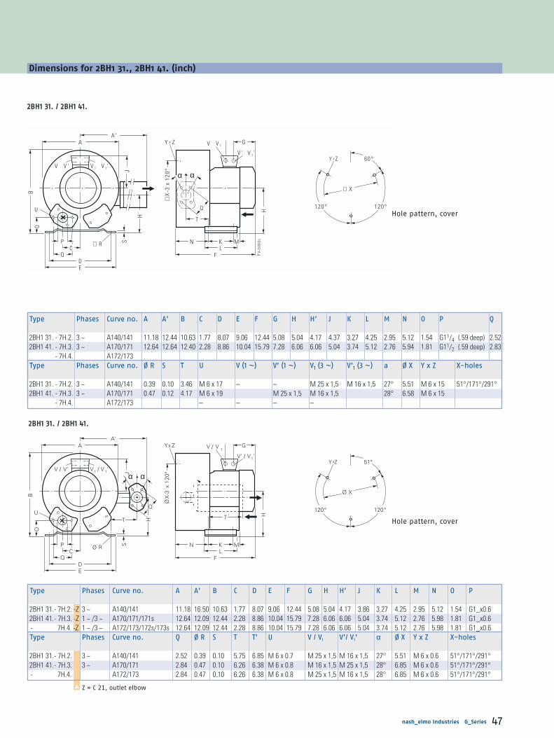
V / V' V1 / V 1'
A
OB
J
U
Ø RPC
DE
GV / V1
H
N K ML
F
xY ZA'
S
Q
120°
51°
Ø X
120°
V' / V1'
ØX
-3 x
120
°
xY Z
T '
Q
α α
H'
T
PV
-506
0c
V V ' V 1 V 1'
A
OB
J
U
∅ RPC
DE
GV V 1
H
N K ML
F
xY ZA'
H'
S
Q
α α
Q
T
120°
60°
∅ X
120°
V ' V 1'
∅X
-3x
120°
xY Z
nash_elmo Industries G_Series 47
Dimensions for 2BH1 31., 2BH1 41. (inch)
22BBHH11 3311.. // 22BBHH11 4411..
Hole pattern, cover
Type Phases Curve no. A A’ B C D E F G H H’ J K L M N O P Q
2BH1 31. - 7H.2. 3 ~ A140/141 11.18 12.44 10.63 1.77 8.07 9.06 12.44 5.08 5.04 4.17 4.37 3.27 4.25 2.95 5.12 1.54 G11/4 (.59 deep) 2.522BH1 41. - 7H.3. 3 ~ A170/171 12.64 12.64 12.40 2.28 8.86 10.04 15.79 7.28 6.06 6.06 5.04 3.74 5.12 2.76 5.94 1.81 G11/2 (.59 deep) 2.83
- 7H.4. A172/173Type Phases Curve no. Ø R S T U V (1 ~) V’ (1 ~) V1 (3 ~) V’1 (3 ~) a Ø X Y x Z X-holes
2BH1 31. - 7H.2. 3 ~ A140/141 0.39 0.10 3.46 M 6 x 17 – – M 25 x 1,5 M 16 x 1,5 27° 5.51 M 6 x 15 51°/171°/291°2BH1 41. - 7H.3. 3 ~ A170/171 0.47 0.12 4.17 M 6 x 19 M 25 x 1,5 M 16 x 1,5 28° 6.58 M 6 x 15
- 7H.4. A172/173 – – – –
Type Phases Curve no. A A’ B C D E F G H H’ J K L M N O P
2BH1 31.- 7H.2. -Z 3 ~ A140/141 11.18 16.50 10.63 1.77 8.07 9.06 12.44 5.08 5.04 4.17 3.86 3.27 4.25 2.95 5.12 1.54 G1_x0.62BH1 41.- 7H.3. -Z 1 ~ /3 ~ A170/171/171s 12.64 12.09 12.44 2.28 8.86 10.04 15.79 7.28 6.06 6.06 5.04 3.74 5.12 2.76 5.98 1.81 G1_x0.6- 7H.4. -Z 1 ~ /3 ~ A172/173/172s/173s 12.64 12.09 12.44 2.28 8.86 10.04 15.79 7.28 6.06 6.06 5.04 3.74 5.12 2.76 5.98 1.81 G1_x0.6Type Phases Curve no. Q Ø R S T T’ U V / V1 V’/ V1’ α Ø X Y x Z X-holes
2BH1 31.- 7H.2. 3 ~ A140/141 2.52 0.39 0.10 5.75 6.85 M 6 x 0.7 M 25 x 1,5 M 16 x 1,5 27° 5.51 M 6 x 0.6 51°/171°/291°2BH1 41.- 7H.3. 3 ~ A170/171 2.84 0.47 0.10 6.26 6.38 M 6 x 0.8 M 16 x 1,5 M 25 x 1,5 28° 6.85 M 6 x 0.6 51°/171°/291°- 7H.4. A172/173 2.84 0.47 0.10 6.26 6.38 M 6 x 0.8 M 25 x 1,5 M 16 x 1,5 28° 6.85 M 6 x 0.6 51°/171°/291°
Z = C 21, outlet elbow▲
22BBHH11 3311.. // 22BBHH11 4411..
Hole pattern, cover

PV
-506
1c
V 1 V 1'
A
SO
B
J
U
Ø R
P QCDE
G
H
N K ML
F
xY ZW
V V '
ØX
12 0°
12 0°Y x Z
ØX
-3x
120°
V ' V 1'
V V 1
Dimensions
48 nash_elmo Industries G_Series
Dimensions for 2BH1 50., 2BH1 59., 2BH1 60., 2BH1 69. (inch)
Type Phases Curve no. A B C D E F G H J K L M N O P Q Ø R
2BH1 50. - 7A.1. 1. ~ A192s/193s 13.15 13.27 4.72 10.24 11.61 12.32 6.14 6.89 4.72 4.53 6.10 3.78 3.43 1.89 2.17 3.27 0.55- 7A.2. A196s/197s 13.58 7.40 5.04
2BH1 50. - 7A.0. 3 ~ A190/191 12.36 6.02 4.72- 7A.1. A192/193- 7A.2. A194/195 13.62 7.28 5.04- 7A.3. A196/197
2BH1 59. - 7AA2. 1 ~ A180s 11.61 13.58 7.40 6.87 0.59- 7AB2. A181s- 7AE1. 3 ~ A180 12.36 6.02 4.72- 7AH2. A181 13.58 7.28 5.04
2BH1 60. - 7A.0. 3 ~ A220 15.04 15.12 4.92 11.42 12.80 14.84 7.80 5.51 7.09 3.31 4.29 2.13- 7A.1. A222/223- 7A.2. A224/225 16.18 7.48 5.31- 7A.3. A226/227 17.00 8.31 5.83
2BH1 69. - 7A.1. A210 14.84 3.35 5.04- 7A.2. A210/211 5.31
Type Phases Curve no. S U V (1 ~) V’ (1 ~) V1 (3 ~) V’1 (3 ~) Ø X Y x Z X-holes W
2BH1 50. - 7A.1. 1 ~ A192s/193s 0.16 M 8 x 17 M 16 x 1.5 M 25 x 1.5 – – 7.87 M 8 x 20 0°/120°/240° 1.26- 7A.2. A196s/197s – –
2BH1 50. - 7A.0. 3 ~ A190/191 – – M 25 x 1.5 M 16 x 1.5- 7A.1. A192/193 – –- 7A.2. A194/195 – –- 7A.3. A196/197 – –
2BH1 59. - 7AA2. 1 ~ A180s M 16 x 1.5 M 25 x 1.5 – –- 7AB2. A181s – –- 7AE1. 3 ~ A180 – – M 25 x 1.5 M 16 x 1.5- 7AH2. A181 – –
2BH1 60. - 7A.0. 3 ~ A220 0.18 – – 9.45 M 10 x 20 - 7A.1. A222/223 – – – –- 7A.2. A224/225 M 32 x 1.5 M 32 x 1.5 M 32 x 1.5 M 32 x 1.5 1.65- 7A.3. A226/227
2BH1 69. - 7A.1. 3 ~ A210 – – M 25 x 1.5 M 16 x 1.5 1.26- 7A.2. A210/211 M 32 x 1.5 M 32 x 1.5 M 32 x 1.5 M 32 x 1.5 1.65
Hole pattern, cover
22BBHH11 5500.. // 22BBHH11 5599.. 22BBHH11 6600.. // 22BBHH11 6699..

120°
120°
Ø X
51,5°xY Z
PV
-509
6
V1 / V 1'
A
OB
JU
Ø RC
P
DE
G
V' / V1'
H
N K ML
F
xA'
H'
S
Q
T’
T
W
ØX
-3 x
120
°V / V'
V / V1
Y Z
T
Q
α α
PV
-509
7
M
O
CC’
nash_elmo Industries G_Series 49
Type Phases Curve no. A A’ B C C’ D E F G H H’ J K L M N O
2BH1 51. -7H.1.-Z 3 ~ A200/201 14.65 14.53 14.69 2.36 - 10.24 11.61 19.49 7.48 6.89 5.67 5.32 4.53 6.10 3.86 6.73 1.892BH1 51. -7H.5.-Z 3~ A202/203 14.65 14.53 14.69 2.36 - 10.24 11.61 19.65 8.82 6.89 5.67 5.32 4.53 6.10 3.86 6.73 1.892BH1 61. -7H.1.-Z 3~ A230/231 16.73 14.88 16.54 2.48 - 11.41 12.80 18.62 7.09 7.80 6.42 5.59 5.51 7.09 3.31 8.07 2.132BH1 61. -7H.2.-Z 3~ A232/233 16.73 14.88 16.54 2.48 - 11.41 12.80 18.62 7.09 7.80 6.42 5.59 5.51 7.09 3.31 8.07 2.132BH1 61. -7H.3.-Z 3~ A234/235 16.73 14.88 16.54 2.48 - 11.41 12.80 18.62 7.09 7.80 6.42 5.59 5.51 7.09 3.31 8.07 2.132BH1 61. -7H.4.-Z 3~ A236/237 16.73 14.88 16.54 6.06 7.72 11.41 12.80 18.62 7.09 7.80 6.42 5.59 5.51 7.09 3.31 8.07 3.702BH1 61. -7H.5.-Z 3~ A238/239 16.73 14.88 16.54 6.06 7.72 11.41 12.80 18.62 7.09 7.80 6.42 5.59 5.51 7.09 3.31 8.07 3.70Type Phases Curve no. Ø P Q Ø R S T T’ U V/V1 V’/V1’ α Ø X Y x Z X-holes W
2BH1 51. -7H.4.-Z 3~ A200/201 2.17 3.27 0.55 0.16 7.80 9.21 M8x0.67 M32x1.5 M32x1.5 23.5° 7.87 M8x0.79 51°/171°/291° 1.652BH1 51. -7H.5.-Z 3~ A202/203 2.17 3.27 0.55 0.16 7.80 9.21 M8x0.67 M32x1.5 M32x1.5 23.5° 7.87 M8x0.79 51°/171°/291° 1.652BH1 61. -7H.1.-Z 3~ A230/231 2.17 3.27 0.59 0.18 7.56 8.70 M8x0.67 M25x1.5 M16x1.5 23.5° 9.45 M10x0.79 51°/171°/291° 1.262BH1 61. -7H.2.-Z 3~ A232/233 2.17 3.27 0.59 0.18 7.56 8.70 M8x0.67 M25x1.5 M16x1.5 23.5° 9.45 M10x0.79 51°/171°/291° 1.652BH1 61. -7H.3.-Z 3~ A234/235 2.17 3.27 0.59 0.18 7.56 8.70 M8x0.67 M32x1.5 M32x1.5 23.5° 9.45 M10x0.79 51°/171°/291° 1.652BH1 61. -7H.4.-Z 3~ A236/237 2.17 3.27 0.59 0.18 7.56 8.70 M8x0.67 M32x1.5 M32x1.5 23.5° 9.45 M10x0.79 51°/171°/291° 1.652BH1 61. -7H.5.-Z 3~ A238/239 2.17 3.27 0.59 0.18 7.56 8.70 M8x0.67 M32x1.5 M32x1.5 23.5° 9.45 M10x0.79 51°/171°/291° 1.65
Dimensions for 2BH1 51., 2BH1 61., 2BH1 64. (inch)
Z = C 21, outlet elbow▲
Hole pattern, cover
22BBHH11 6611..--......44..--......55..
22BBHH11 5511..22BBHH11 6611..--......11..
--......22..--......33..

120°
120°
∅ X
xY Z
PV
-506
4d
V
A
OB
J
U
∅ R
C
P
DE
G
V
N K ML
x
HS
Q
42
F
∅X
-3x
120°
V
Y Z
PV
-506
5a
M
O
C '209
120°
120°
∅ X
51 ,5°xY Z
PV
-506
2d
V 1 V 1'
A
OB
J
U
∅ RC
P
DE
G
V ' V 1'
H
N K ML
F
xA '
H'
S
Q
Q
T
23 ,5° 23 ,5°
W
51 5°
∅X
-3x
120°
V V '
V V 1
Y Z
O
C209
PV
-506
3a
M
Dimensions
50 nash_elmo Industries G_Series
Dimensions for 2BH1 51., 2BH1 61., 2BH1 64. (inch)
Type Curve no. A B C C’ D E F G H J K L M N
2BH1 64. - 7G.3. A260/261 16.69 16.93 4.92 – 11.42 12.80 20.79 8.31 8.58 5.83 5.51 7.40 3.31 8.07- 7G.4. A262/263 – 12.17 22.40 8.82 6.57 8.86- 7G.5. A264/265 –
Type Curve no. O Ø P Q Ø R S U V Ø X Y x Z X-holes
2BH1 64. - 7G.3. A260/261 2.91 2.17 3.27 0.59 0.96 M 8 x 17 4 x M 32 x 1.5 9.45 M 10 x 20 0°/120°/240°- 7G.4. A262/263 4.49- 7G.5. A264/265
Type Curve no. A A’ B C D E F G H H’ J K L M N O Ø P Q
2BH1 51. - 7H.4. A200/201 14.65 16.18 14.61 2.36 10.24 11.61 18.31 7.48 6.89 5.67 5.31 4.53 6.10 3.86 6.73 1.89 2.17 3.27- 7H.5. A202/203 19.65 8.82
2BH1 61. - 7H.1. A230/231 16.77 16.69 16.54 2.48 11.42 12.80 18.62 7.28 7.80 6.46 5.04 5.51 7.09 3.31 8.07 2.13- 7H.2. A232/233 19.96 7.48 5.31- 7H.3. A234/235 20.79 8.31 5.83- 7H.4. A236/237 6.06 22.44 8.86 6.57 8.86 3.70- 7H.5. A238/239
Type Curve no. Ø R S T U V V’ V1 V’1 Ø X Y x Z X-holes W
2BH1 51. - 7H.4. A200/201 0.55 0.16 4.57 M 8 x 17 4 x M 32 x 1.5 7.87 M 8 x 20 51.5°/171.5°/291.5° 1.65- 7H.5. A202/203
2BH1 61. - 7H.1. A230/231 0.59 0.18 5.08 M 8 x 17 M 25 x 1.5 M 16 x 1.5 – – 9.45 M 10 x 20 1.26- 7H.2. A232/233 – – 1.65- 7H.3. A234/235 4 x M 32 x 1.5- 7H.4. A236/237- 7H.5. A238/239
Hole pattern, cover
22BBHH11 6611..--......44..--......55..
22BBHH11 5511..22BBHH11 6611..--......11..
--......22..--......33..
22BBHH11 6644..--......44..--......55..
22BBHH11 6644..--......33..
Hole pattern, cover

PV
-50
67
a
J
RE
A'
F
xY Z
D
B
W
N'
V
SKNL
HO
2
C 2
C 1
O1
P
A
M'
G
F'
X
xY Z
B
120°
120°
ØX -
3x12
0°
A
OB
RC
ED
JS
B
P
PV
-506
6b
G
F
xY Z
F '
W
M'N
V
H
KML
X
15
xY Z
ØX -
3x12
0°
120°
120°
PV
-506
8b
RD
F
xY Z
J
W
V
KNL
H
C
E
A
OB
S
G
F'
P
X
xY Z
Ø X
- 3x1
20°
120°
120°
75°
nash_elmo Industries G_Series 51
Dimensions for 2BH1 80., 2BH1 81., 2BH1 84. (inch)
Type Curve no. A B C D E F F’ G H J K L N2BH1 84. - 7J.2. A320/321 19.61 25.67 6.30 14.37 16.54 20.51 23.54 8.82 10.43 6.58 11.02 12.44 5.55
- 7J.3. A322/323 27.05 11.46 7.76Type Curve no. O Ø P Ø R S V W Ø X Y x Z X-holes2BH1 84. - 7J.2. A320/321 12.52 21/2”F-NPT 0.59 0.87 4 x M 32 x 1.5 1.65 16.06 M 12 x 20 75°/195°/315°
- 7J.3. A322/323 4 x M 40 x 1.5 2.13
Type Curve no. A A’ B B’ C C1 C2 D E F F’ G H J K L M M’ N
2BH1 80. - 7A.0. A270/271 19.61 – 20.24 22.32 5.71 – – 14.37 16.54 19.49 18.50 8.31 10.43 5.83 11.02 12.44 1.38 0.39 6.69- 7A.1. A272/273 19.41 8.82 6.57- 7A.2. A274/275
2BH1 81. - 7H.1. A280/281 19.72 25.04 20.31 – 12.52 2.70 23.66 23.54 – 15.83 5.53- 7H.2. A282/283- 7H.3. A284/285 2.87 28.58 27.05 11.46- 7H.4. A286/287
Type Curve no. N’ O O1 O2 Ø P Ø R S V W Ø X Y x Z X-holes
2BH1 80. - 7A.0. A270/271 – 3.19 – – 21/2”F-NPT 0.59 0.87 2 x Pg 21 1.65 16.06 M 12 x 20 15°/135°/255°- 7A.1. A272/273- 7A.2. A274/275
2BH1 81. - 7H.1. A280/281 4.09 – 2.60 7.32 21/2”F-NPT 4 x M 52 x 1.5 0°/120°/240°- 7H.2. A282/283- 7H.3. A284/285 9.21 4 x M 40 x 1.5 2.13- 7H.4. A286/287
22BBHH11 8800..
Hole pattern, cover Hole pattern, cover
22BBHH11 8811..
22BBHH11 8844 11..
Hole pattern, cover

P-5
09
b
V
A
O
B
RPC '
DE
G
V
NM
F '
F 'C
HB
1
W
F
S
K
Q6,5
X
1°
1°
Ø - 3
x 2
0°V
A
O
B
U
RPC'
DE
G
V
NMF''
xY Z
A'
Q
C
HJ
B
W
F
S
K
26,5˚ 120˚
51˚
X
120˚
xY Z
X-3
x120
˚
H'
T
Q
'
F'
T'Ø
Ø
Ø
PV-
5099
Dimensions
52 nash_elmo Industries G_Series
Dimensions for 2BH1 91., 2BH1 90. (inch)
Type Curve no. A B B1 C C’ D E F F’ F’’ G H J K M N2BH1 90. und2BH1 93. - 7A.0. A330/331/350/351 21.85 22.44 2.44 8.15 0.59 14.17 16.34 21.38 28.58 26.54 10.47 11.81 6.57 23.47 2.05 4.25
- 7A.1. A332/333/352/353 24.84 13.58 7.76- 7A.3. A334/335/354/355
Type Curve no. O Ø P Q Ø R S U V W Ø X Y x Z X-holes2BH1 90. und2BH1 93. - 7A.0. A330/331/350/351 3.58 3.94 5.91 0.59 0.98 M 12 x 30 4 x M32 x 1.5 1.65 19.29 M 12 x 30 0°/120°/240°
- 7A.1. A332/333/352/353 4 x M40 x 1.5 2.13- 7A.3. A334/335/354/355
Type Phases Curve no. A A’ B B’ C C’ D E F F’ F’’ G H H’ J K M N2BH1 91.-7H.1.-Z 3~ A340/341 22.05 20.59 22.40 2.48 4.09 0.59 14.17 16.34 30.12 33.86 26.02 9.65 11.81 9.67 7.65 23.47 1.69 9.532BH1 91.-7H.2.-Z 3~ A342/343 22.05 20.59 22.40 2.48 4.09 0.59 14.17 16.34 30.12 33.86 26.02 9.65 11.81 9.67 7.65 23.47 1.69 9.532BH1 91.-7H.3.-Z 3~ A344/345 22.05 20.59 22.40 2.48 4.09 0.59 14.17 16.34 30.12 33.86 26.02 9.65 11.81 9.67 7.65 23.47 1.69 9.53Type Phases Curve no. O Ø P Q Ø R S T U V W Ø X Y x Z X-holes2BH1 91.-7H.1.-Z 3~ A340/341 3.58 3.94 5.91 0.59 0.98 3.74 M 12 x 1.2 M40 x 1.5 2.13 19.29 M 12 x 1.2 51°/171°/291°2BH1 91.-7H.2.-Z 3~ A342/343 3.58 3.94 5.91 0.59 0.98 3.74 M 12 x 1.2 M40 x 1.5 2.13 19.29 M 12 x 1.2 51°/171°/291°2BH1 91.-7H.3.-Z 3~ A344/345 3.58 3.94 5.91 0.59 0.98 3.74 M 12 x 1.2 M40 x 1.5 2.13 19.29 M 12 x 1.2 51°/171°/291°
Hole pattern, cover
Z = C 21, outlet elbow▲
22BBHH11 9911..
Hole pattern, cover
22BBHH11 9900.. // 11 993300

B
A
Q
ØP'
U C E
P V -5027c
75 M8
12 0°
12 0°
D
M8
Y Z
Foot 1 Foot 2
Foot 3Foot 4
Hole pattern,cover
3.41
3.94
PV
-50
70
b
V
A
O
B
U
RPC'
DE
G
V
NMF''
F '
xY Z
A'
H'
Q
C
HJ
B1 W
F
T
S
K
26.5
Q
X
xY Z
Ø X
- 3x1
20°
50°
120°120°
Ø
°
Y Z
P
F"
F
W
V
F'
G
S
X
nash_elmo Industries G_Series 53
Dimensions for 2BH1 91., 2BH1 943 (inch)
22BBHH11 994433(only cover mounting possible)Dimensions for fixing elements2BX2 124 see page 52(not included in the scope of supply of the pump/compressor).
Type Curve no. A B C D E F F’ F’’ G P P’
2BH1 943 - 7G.2. A380/381 22.05 28.15 12.09 19.29 22.05 47.28 30.12 23.62 13.58 9.92 5.12- 7G.3. A382/383- 7G.4. A384/385 33.27 15.16
Type Curve no. Q S U V W Y x Z
2BH1 943 - 7G.2. A380/381 8.27 1.57 M 16 x 30 2 x M 40 x 1.5 2.13 M 12 x 10.5- 7G.3. A382/383- 7G.4. A384/385
Type Curve no. A A’ B B1 C C’ D E F F’ F’’ G H H’ J K M
2BH1 91. - 7H.1. A340/341 22.05 31.34 22.83 2.05 4.09 0.59 14.17 16.34 30.12 33.86 26.02 11.46 11.81 9.65 7.76 23.46 2.05- 7H.2. A342/343- 7H.3. A344/345
Type Curve no. N O Ø P Q Ø R S T U V W Ø X Y x Z X-holes
2BH1 91. - 7H.1. A340/341 9.53 3.58 3.94 5.91 0.59 0.98 3.74 M 12 x 30 4 x M40 x 1.5 2.13 19.29 M 12 x 30 51.4°/171.4°/291.4°- 7H.2. A342/343- 7H.3. A344/345
22BBHH11 994433..
22BBHH11 9911..
View X
Hole pattern, cover

V2V1
F
G
A
J
B
F
GV2
V1
F
G
V1V2
B
Dimensions
54 nash_elmo Industries G_Series
Dimensions for 2BH1 with converter (inch)
Type Curve no. A B F G V1 V2
2BH1 400-0AN21 A162e - 15.83 12.80 7.01 M25+M20 3 x M162BH1 500-0AN31 A193e - 16.71 17.38 10.94 M252BH1 600-0AN31 A223e - 18.56 18.742BH1 800-0AN01 A270e 20.57 - 21.22
Type Curve no. A B F G V1 V2
2BH1 800-0AN01 A270e 20.57 - 21.22 10.94 M25 3 x M16
Type Curve no. A B F G V1 V2
2BH1310-0AN21 A142e - 14.49 14.65 7.01 M25+M20 3 x M162BH1410-0AN41 A174e - 15.59 19.55 10.94 M252BH1510-0AN51 A205e - 17.15 20.832BH1610-0AN31 A233e - 18.56 22.52 M25+M20
22BBHH11 880000
22BBHH11 331100 ...... 22BBHH11 661100
22BBHH11 440000 ...... 22BBHH11 660000

nash_elmo Industries G_Series 55

Dimensions
56 nash_elmo Industries G_Series
Dimensions for 2BH7 63. (inch)
Dimensions for 2BH7 2., 2BH7 3., 2BH7 4., 2BH7 5., 2BH7 6. (inch)
Type Curve no. A B B’ C2 D E F G H H1 K M N2BH7 630 - 0AH6.-. B282/283 17.40 18.00 19.49 2.48 14.61 15.98 27.95 10.51 9.29 15.31 6.57 21.18 13.35Type Curve no. O P Q R S1 S2 T U V W1 W22BH7 630 - 0AH6.-. B282/283 6.77 G 11/4 2.52 0.55 0.20 5.75 6.02 M 6 x 17 for M 32 x 1.5 1.65 5.51
(.71 deep)
Type Curve no. A B B’ B1 C C2 D E F G H H1 J K M N O P
2BH7 210 - 0AH1. B140/141 11.57 12.56 – 1.54 3.43 – 10.24 11.73 11.54 5.08 6.57 – 4.37 4.13 9.92 2.56 4.88 G 11/42BH7 310 - 0AH1. B170/171 12.32 13.35 – 3.70 – 11.42 12.80 11.61 6.97 – 4.72 10.08 2.64 5.12 (.71deep)
- 0AH2. B172/1732BH7 410 - 0AH1. B200/201 13.62 14.76 – 1.50 4.06 – 12.40 13.78 12.64 6.02 7.68 – 5.12 10.24 2.60 5.632BH7 510 - 0AH1. B230/231 14.49 15.55 – 1.54 4.49 – 12.91 14.29 14.21 7.28 8.07 – 5.04 5.98 10.43 2.68 5.83
- 0AH2. B232/2332BH7 610 - 0AH1. B260/261 16.46 17.91 – 5.00 – 14.61 15.98 14.33 7.28 9.25 – 10.67 2.84 6.77
- 0AH3. B263/264 15.35 8.312BH7 220 - 0AH2. B150/151 12.32 12.84 14.13 – – 1.69 10.24 11.73 18.46 5.12 6.57 10.71 4.37 16.77 9.49 4.84 G 11/4
- 0AH5. B152/153 20.67 7.28 5.04 (.71deep)2BH7 320 - 0AH5. B182/283 13.03 13.58 14.96 – – 1.85 11.42 12.80 19.49 6.02 6.97 11.46 4.72 16.97 9.57 5.122BH7 420 - 0AH2. B210/211 14.29 14.84 16.30 – – 2.05 12.40 13.78 20.83 7.09 7.68 12.56 5.04 5.12 17.17 5.63
- 0AH5. B212/213 21.81 8.312BH7 520 - 0AH2. B240/241 15.24 15.83 17.13 – – 2.24 12.91 14.29 21.61 7.28 8.11 13.50 5.04 5.98 17.83 10.08 5.83
- 0AH7. B244/245 23.74 8.31 5.832BH7 620 - 0AH3. B270/271 17.40 17.99 19.49 – – 2.48 14.65 15.98 22.76 9.29 15.31 5.04 18.03 10.20 6.81
- 0AH5. B272/273 25.31 9.76 5.83Type Curve no. Q R S1 S2 S3 T T1 U V V 1 W X Y x Z
2BH7 210 - 0AH1. B140/141 2.52 0.55 0.16 5.51 1.22 4.13 4.21 M 6 x 17 M 25 x 1.5 M 16 x 1.5 1.26 6.02 M 6 x 152BH7 310 - 0AH1. B170/171 4.49 4.57
- 0AH2. B172/1732BH7 410 - 0AH1. B200/201 4.92 5.00 6.572BH7 510 - 0AH1. B230/231 0.20 5.39 5.43 7.56 M 8 x 15
- 0AH2. B232/2332BH7 610 - 0Ah1. B260/261 6.02 6.10 8.98
- 0AH3. B263/2642BH7 220 - 0AH2. B150/151 2.51 0.16 4.13 4.21 – –
- 0AH5. B152/153 – –2BH7 320 - 0AH5. B182/283 4.49 4.57 – –2BH7 420 - 0AH2. B210/211 4.92 5.00 – –
- 0AH5. B212/213 – –2BH7 520 - 0AH2. B240/241 0.20 5.39 5.43 1.65 – –
- 0AH7. B244/245 2 x M 32 x 1.5 1.26 – –2BH7 620 - 0AH3. B270/271 6.02 6.10 M 25 x 1.5 1.65 – –
- 0AH5. B272/273 2 x M 32 x 1.5 – –

A
B
TDE
J
PV
-533
7a
U
O
Q P
S1 N K
MF
H
H1
S 2
C 2
B'
V
GW1
R
W2
CO
PQ
B
S1
H
X
B1
∅ R
∅X
V
G
PV
-534
1a
J
A
S 3
Y x Z
S 2
N KM
F
TT 1
DE
U Y x Z
∅ X135°
90°
WV 1
A
B
TT 1
DE
J
PV
-531
0a
U
O
Q P
S1 N K
MF
H
H1
S 2C 2
B'
V
GW
∅ R
V 1
A
B
TT 1
DE
J
PV
-531
0a
U
O
Q P
S1 N K
MF
H
H1
S 2C 2
B'
V
GW
∅ R
V 1
CO
PQ
B
S1
H
X
B1
∅ R
∅X
V
G
PV
-534
1a
J
A
S 3
Y x Z
S 2
N KM
F
TT 1
DE
U Y x Z
∅ X135°
90°
WV 1
nash_elmo Industries G_Series 57
Dimensions for 2BH7 2., 2BH7 3., 2BH7 4., 2BH7 5., 2BH7 6. (inch)
Hole pattern, cover
22BBHH77 2211.. // 22BBHH77 3311.. // 22BBHH77 4411.. // 22BBHH77 5511.. // 22BBHH77 6611..
22BBHH77 2222.. // 22BBHH77 3322.. // 22BBHH77 4422.. // 22BBHH77 5522.. // 22BBHH77 6622..
Hole pattern, cover
22BBHH77 2211.. // 22BBHH77 3311.. // 22BBHH77 4411.. // 22BBHH77 5511.. // 22BBHH77 6611..
22BBHH77 2222.. // 22BBHH77 3322.. // 22BBHH77 4422.. // 22BBHH77 5522.. // 22BBHH77 6622..
22BBHH77 6633..
Dimensions for 2BH7 63. (inch)

B
V2V1
G
F
B
V2V1
G
F
Dimensions
58 nash_elmo Industries G_Series
Dimensions for 2BH7 with converter (inch)
Type Curve no. B F G V1 V2
2BH7 210-0AN11 B141e 16.02 13.74 7.01 M25+M20 3 x M162BH7 210-0AN51 B145e 16.40 18.48 10.95 M252BH7 310-0AN21 B172e 16.42 13.82 7.01 M25+M202BH7 310-0AN61 B176e 16.79 17.58 10.95 M252BH7 410-0AN11 B201e 17.44 13.94 7.01 M25+M202BH7 410-0AN51 B205e 17.50 16.06 10.95 M252BH7 510-0AN21 B232e 17.89 17.972BH7 510-0AN61 B236e 18.33 18.032BH7 610-0AN31 B263e 19.07 16.54
22BBHH77 221100 ...... 22BBHH77 661100
22BBHH77 222200 ...... 22BBHH77 662200
Type Curve no. B F G V1 V2
2BH7 220-0AN51 B155e 16.40 24.43 11.30 M25 3 x M162BH7 320-0AN51 B185e 16.79 24.512BH7 320-0AN81 B188e 22.912BH7 420-0AN21 B212e 17.50 24.592BH7 420-0AN51 B215e 22.992BH7 520-0AN71 B247e 18.88 25.472BH7 620-0AN31 B273e 19.11 23.94
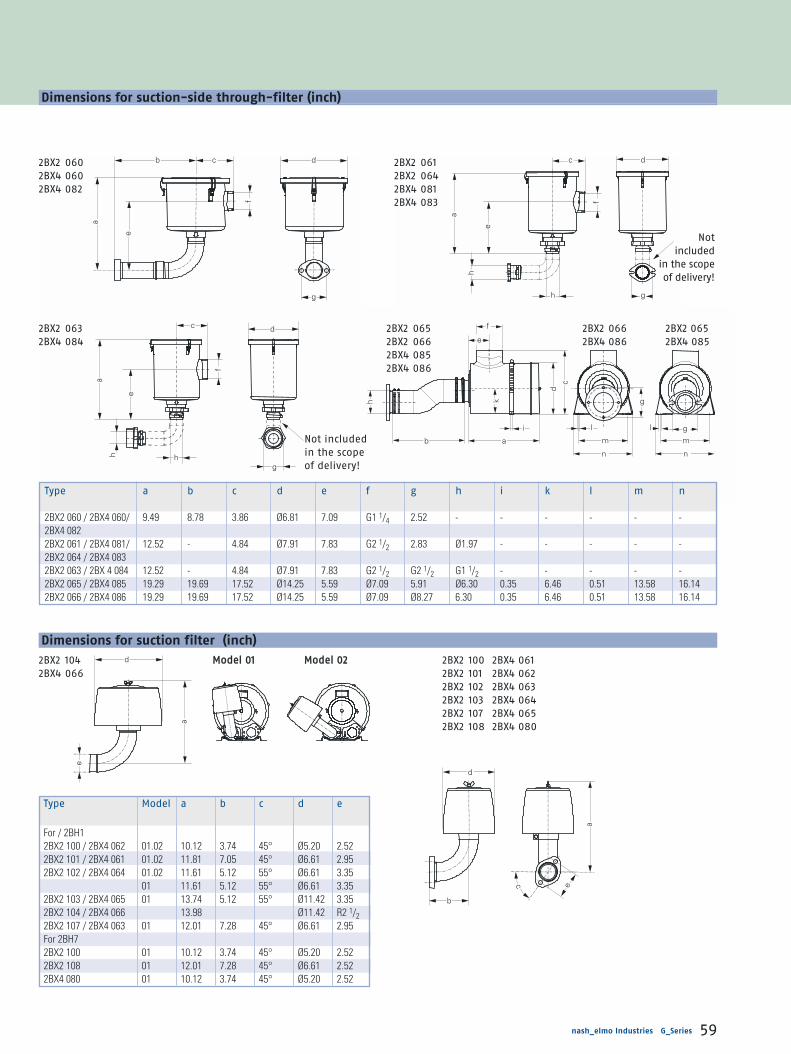
d
b
c e
a
a
e
d
c d
f
e
a
h hg
f
e
bb ba
i
kh
dc
g
l
m
n n
mgl
c d
f
e
a
h
h g
b cb
a
e
f
d
g
nash_elmo Industries G_Series 59
Dimensions for suction-side through-filter (inch)
Dimensions for suction filter (inch)
Type Model a b c d e
For / 2BH12BX2 100 / 2BX4 062 01.02 10.12 3.74 45° Ø5.20 2.522BX2 101 / 2BX4 061 01.02 11.81 7.05 45° Ø6.61 2.952BX2 102 / 2BX4 064 01.02 11.61 5.12 55° Ø6.61 3.35
01 11.61 5.12 55° Ø6.61 3.352BX2 103 / 2BX4 065 01 13.74 5.12 55° Ø11.42 3.352BX2 104 / 2BX4 066 13.98 Ø11.42 R2 1/22BX2 107 / 2BX4 063 01 12.01 7.28 45° Ø6.61 2.95For 2BH72BX2 100 01 10.12 3.74 45° Ø5.20 2.522BX2 108 01 12.01 7.28 45° Ø6.61 2.522BX4 080 01 10.12 3.74 45° Ø5.20 2.52
2BX2 100 2BX4 0612BX2 101 2BX4 0622BX2 102 2BX4 0632BX2 103 2BX4 0642BX2 107 2BX4 0652BX2 108 2BX4 080
MMooddeell 0011 MMooddeell 00222BX2 1042BX4 066
Type a b c d e f g h i k l m n
2BX2 060 / 2BX4 060/ 9.49 8.78 3.86 Ø6.81 7.09 G1 1/4 2.52 - - - - - -2BX4 0822BX2 061 / 2BX4 081/ 12.52 - 4.84 Ø7.91 7.83 G2 1/2 2.83 Ø1.97 - - - - -2BX2 064 / 2BX4 0832BX2 063 / 2BX 4 084 12.52 - 4.84 Ø7.91 7.83 G2 1/2 G2 1/2 G1 1/2 - - - - -2BX2 065 / 2BX4 085 19.29 19.69 17.52 Ø14.25 5.59 Ø7.09 5.91 Ø6.30 0.35 6.46 0.51 13.58 16.142BX2 066 / 2BX4 086 19.29 19.69 17.52 Ø14.25 5.59 Ø7.09 Ø8.27 6.30 0.35 6.46 0.51 13.58 16.14
2BX2 0602BX4 0602BX4 082
Not included in the scope of delivery!
2BX2 0632BX4 084
2BX2 0612BX2 0642BX4 0812BX4 083
Not included
in the scope of delivery!
2BX2 065 2BX2 066 2BX2 0652BX2 066 2BX4 086 2BX4 0852BX4 0852BX4 086

f
a
d
e cb
fb
a
e
d
f
b
c
e
a
d
h
f
e
a
b
c
d
e
d
g
a
bf
c
d
e
g
bc
fa
f
a
d
e c
b
g
h
i
VViieeww XX::
2BX4 010 2BX4 0142BX4 011
2BX4 015 2BX4 000
2BX4 013
Dimensions
60 nash_elmo Industries G_Series
Type a b c d e f g
2BX4 000 0.35 1.77 1.57 Ø3.27 Ø1.59 11.54 2.522BX4 010 0.35 1.77 1.57 Ø3.50 Ø1.99 11.57 2.832BX4 011 0.35 1.77 1.57 Ø2.95 Ø1.59 11.54 2.522BX4 012 1.26 2.56 2.20 Ø5.20 Ø3.15 25.63 G2 1/22BX4 013 0.87 2.95 2.36 Ø6.57 Ø4.53 25.90 5.912BX4 014 0.87 3.15 2.36 Ø8.23 Ø5.91 26.06 Ø8.272BX4 015 0.35 1.77 1.57 Ø3.46 Ø1.99 11.54 2.84
Dimensions for additional silencer (inch)
Dimensions for 90° elbow (inch)
Type a b c d e f
2BX4 313 0.55 3.80 0.55 3.88 21.5° 2.522BX4 314 0.55 4.19 0.55 4.19 18° 2.952BX4 315 0.63 5.18 0.63 5.18 23.5° 3.352BX4 319 0.87 4.80 0.87 4.80 0° 5.91
VViieeww XX::
Type a b c d e f g h i
2BX1 037 G1 1/4 0.55 2.20 2.54 0.37 3.15 - - -2BX1 038 G1 1/2 0.55 2.83 2.95 0.37 3.94 - - -2BX1 040 G1 1/2 0.55 2.83 2.95 0.37 3.94 R 3.94 1.22 57.5°2BX1 041 G2 0.63 3.15 3.35 0.47 4.41 - - -2BX1 042 G4 0.87 5.51 5.91 0.55 7.48 - - -2BX1 043 G5 0.87 - Ø8.27 0.71 Ø9.84 - - -2BX4 040 G1 1/4 0.55 2.20 2.52 0.37 3.15 1.18 0.91 -2BX4 041 NPT2 0.63 3.15 3.35 0.47 4.41 - - -2BX4 042 NPT4 0.87 5.51 5.91 0.55 7.48 - - -2BX4 043 NPT5 0.87 - 8.27 0.71 9.84 - - -
Dimensions for threaded flange (inch)
2BX4 0002BX4 0102BX4 0112BX4 0132BX4 0142BX4 015
2BX4 012
2BX4 3132BX4 3142BX4 3152BX4 319
2BX1 0372BX1 0382BX1 0412BX1 0422BX4 0412BX4 042
2BX1 040 2BX4 040 2BX1 0432BX4 043

h
h
f
g
e
d
a ab
c
af
ec
b
d
a
b
ceg
d
f
a
bc
eg
k
i
h
df
a
cb
g
de
df
a
bc
ge
d
a
b
c
a
bc
g
e
df
h
nash_elmo Industries G_Series 61
Dimensions for hose flange (inch)
Footprint Dimensions for vertical / horizontal mounting (inch)
Dimensions for fixing clamp for 2BH1 943 ( 1 set = 4 feet) (inch)
Type a b c d e f g h i k
2BX1 032 / 2BX4 020 Ø1.58 0.35 1.97 2.52 2.36 3.35 0.41 - / 0.91 - -2BX1 033 Ø1.97 0.35 1.97 3.27 2.84 3.94 0.41 - - -2BX1 034 Ø1.97 0.35 1.97 2.83 2.84 3.94 0.41 1.22 57.5° R 3.942BX1 036 Ø2.36 0.35 1.97 3.27 2.91 3.94 0.41 - - -2BX1 046 Ø5.91 0.87 3.23 Ø8.27 Ø9.84 - 0.71 - - -2BX1 047 Ø2.99 1.26 2.95 G2 1/2 - - - - - -2BX1 048 Ø4.53 0.87 3.62 5.91 5.51 7.48 0.71 - - -
Type a b c d e f
2BX2 120 Ø0.98 0.79 0.39 0.24 M6 M62BX2 121 Ø1.18 0.79 0.51 0.30 M8 M82BX2 122 Ø1.97 1.18 0.59 0.39 M10 M102BX2 123 Ø2.95 1.58 0.69 0.41 M12 M122BX2 127 Ø1.38 1.77 0.43 0.31 M6 M62BX2 128 Ø1.38 1.77 0.43 0.31 M8 M82BX2 135 Ø0.98 1.73 0.39 0.23 M6 M6
Type a b c d e f
2BX4 100 Ø0.98 0.79 0.39 0.24 M6 M62BX4 101 Ø1.18 0.79 0.51 0.30 M8 M82BX4 102 Ø1.97 1.18 0.59 0.39 M10 M102BX4 103 Ø2.95 1.57 1.57 0.41 M12 M122BX4 104 Ø2.95 1.57 1.57 0.41 M12 M12
Type a b c d e f g h i
2BX2 124 1.02 Ø0.39 3.27 19.29 3.41 M8 2.95 120° 3.94
2BX2 124Foot 1 Foot 3 Foot 2 Foot 4
Foot 1
Foot 4
Foot 3
Foot 2Hole pattern
2BX1 0322BX1 0332BX1 036
2BX4 020
2BX1 034 2BX1 046
2BX1 047 2BX1 048
2BX2 120 2BX4 1002BX2 121 2BX4 1012BX2 122 2BX4 1022BX2 123 2BX4 1032BX2 127 2BX4 1042BX2 1282BX2 135

f e
d
b
c
f
e
d
b
c
g g
a
g g
af
e
d
b
c
g g
af
e
d
b
c
g g
afe
d
bc
Dimensions
62 nash_elmo Industries G_Series
Type a b c d e f g
2BX2 141 / 142 2BH13 5.24 7.13 Ø1.65 38° Ø0.35 2.52 0.392BX2 171 / 172 2BH14 5.24 7.13 Ø1.65 48° Ø0.35 2.91 0.392BX2 145 / 146 4.45 7.13 Ø1.65 45° Ø0.37 3.27 0.39
e
d
b
g g
a
g g
a
2BX2 1472BX2 148
Dimensions for vacuum relief valve with adaptor (inch)
Dimensions for pressure relief valve with adaptor (inch)
Type a b c d e f g
2BX2 143 / 144 2BH13 5.24 7.13 Ø1.65 38° Ø0.35 2.52 0.392BX2 173 / 174 2BH14 5.24 7.13 Ø1.65 48° Ø0.35 2.91 0.392BX2 147 / 148 4.45 7.13 Ø1.65 45° Ø0.37 3.27 0.39
2BX2 1412BX2 1422BX2 1712BX2 172for 2BH13/2BH7
2BX2 1452BX2 146
2BX2 1412BX2 1422BX2 1712BX2 172for 2BH14
2BX2 1432BX2 1442BX2 1732BX2 174for 2BH14
2BX2 1432BX2 1442BX2 1732BX2 174for 2BH13/2BH7

b
a
c
d
a
d
gbc
e
f
hd
gabc
e
f
c
b
a
d
nash_elmo Industries G_Series 63
Dimensions for vacuum relief valve (supplied loose for pipeline mounting) (inch)
Dimensions for pressure relief valve (supplied loose for pipeline mounting) (inch)
Type a b c d e f g h
2BX2 110 / 114 G1 1/4 Ø1.63 Ø2.36 5.53 - - - -2BX2 150 Ø3.15 Ø6.30 Ø7.87 9.41 Ø0.71 45° 1.61 0.752BX2 152 Ø4.92 Ø8.27 Ø9.84 15.51 Ø0.71 45° 1.81 0.942BX2 154 Ø7.87 Ø11.61 Ø13.39 23.39 Ø0.91 45° 1.89 0.94
Type a b c d e f g
2BX2 111 / 115 G1 1/4 Ø1.63 Ø2.36 5.53 - - -2BX2 151 Ø3.15 Ø6.30 Ø7.87 9.41 Ø0.71 45° 1.612BX2 153 Ø4.92 Ø8.27 Ø9.84 15.51 Ø0.71 45° 1.812BX2 155 Ø7.87 Ø11.61 Ø13.39 23.39 Ø0.91 45° 1.89
2BX2 1502BX2 1522BX2 154
2BX2 1102BX2 114
2BX2 1512BX2 1532BX2 155
2BX2 1112BX2 115

An

nex
Application examples 66 - 75
Conversion tables 76
Physical basics for blower applications 77 - 78
General safety information 79 - 80
Quality 81
ATEX 82
Footnotes and Voltage Overview 83

66 nash_elmo Industries G_Series
G_Series Application examples
Air cushion generation for paper
processing machines
Several little blast pipes which are normally closed by ball valves
are located in the table plate. When the balls are pressed down by
the weight of a paper staple the valve is opened. Floating on an air
cushion the paper now can be easily shifted and positioned.
Air cushioning for air tables
Ball valves used in air tables follow the same principle of
design as those used for paper cutting machines.
As a result most manufacturers of paper cutting machines
also offer air tables.
G
paper
ball
air
Bust pipe
Air table equipped with
a gas ring compressor

nash_elmo Industries G_Series 67
Vacuum generation for screen
printing machines
Blowers used in a suction table generate a vacuum which secures
the paper sheets during the printing process to prevent slipping.
Powder is sprayed on the paper immediately after printing to
avoid smearing of wet colour and sticking of paper to the
machine. For spraying an injector is used.
G
G
paper
pressure plate
paper
suction table
blower
blower powder container
injector nozzle
Powder spraying for printing
machines (Dry and pressure spraying)
Suction table for screen printing
Powder spraying for printing machines

G
68 nash_elmo Industries G_Series
G_Series Application examples
Air arm for printing machines
After passing the printing machine the sheets of paper are turned
over and piled up. Both operations are supported by blast air.
G
printing roller
paper
blower
turn around grating
paper stack
detent
transport system printed side
of the paper
Turning over paper by blast air
Blast air transportation of printed paper
Paper transport by air cushions
To avoid smearing of wet paint the sheets of paper are blown
against a detent with the printed on side facing down.

nash_elmo Industries G_Series 69
G
blower
filter equipped
settling chamber
pressure stamp
blower
paper stack
Sucking in paper clippings at a vacuum table
Loosening stacked paper by blast air
Suction of paper clippings
(e.g. perforating machines, paper cutting machines, punched-
card machines, Hollerith machines etc.)
The paper clippings can be collected in a filter equipped settling
chamber after being sucked off right at their origin.
Aeration of paper piles by blast air
Piled sheets of paper often tend to stick together especially when
their surface is very smooth. Blast air can be used for separation
by forming air cushions between the sheets.
G

70 nash_elmo Industries G_Series
G_Series Application examples
Packing eggs by suction air
Evacuation of fruit packings
G
G
Packing eggs by suction air
Evacuation of fruit packings
lifting,
lowering,
holding
shifting
egg
conveyer belt

nash_elmo Industries G_Series 71
G
Conveying machinery
Depending on their weight and size, the goods to be conveyed
are secured by one or several suction cups.
lifting,
sinking
suction cup
rubber joint
goods to be conveyed
Lifting and transporting by suction air
G
Holding and clamping of workpieces
Suction air generated by a gas ring blower is used to secure the
workpiece during machining. This way of clamping is especially
important for parts that can't be secured by magnetic forces
(e.g. workpieces consisting of wood, plastics, ceramics and
non-ferrous metals).
workpiece
worktable
Clamping workpieces by suction air

72 nash_elmo Industries G_Series
G_Series Application examples
Granulated material conveyers
Automated loading of molding presses and extruders. A blower
generates a vacuum in the container for granulated material
which is transported by the air flow. The gas ring blower is
protected by a filter.
Respirators
Fresh air is needed for breathing while
working in polluted atmospheres. This is
for example necessary in the chemical
industry where big tanks, chambers etc.
have to be cleaned.
Gas ring blowers can provide fresh air for
one or several respirators at the same
time. A hose diameter of 1" and a maxi-
mal hose length of 15 ft are required.
Another possibility is to pump fresh air into
the protective helmet from above so that
no pollutants are inhaled by the worker.
G
filter
pipe
towards the molding press
container for
granulated material
Pneumatic transportation of granulated material
Respirators
G
hose
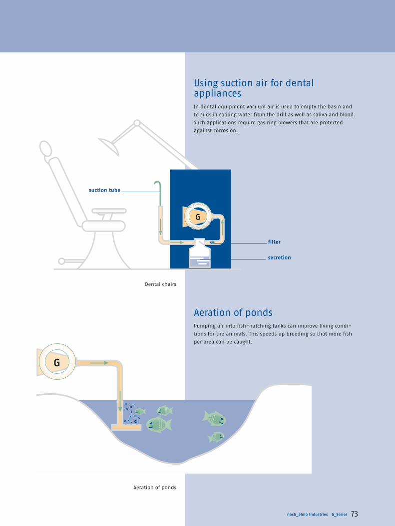
nash_elmo Industries G_Series 73
G
G
Using suction air for dental appliances
In dental equipment vacuum air is used to empty the basin and
to suck in cooling water from the drill as well as saliva and blood.
Such applications require gas ring blowers that are protected
against corrosion.
Aeration of ponds
Pumping air into fish-hatching tanks can improve living condi-
tions for the animals. This speeds up breeding so that more fish
per area can be caught.
filter
secretion
suction tube
Aeration of ponds
Dental chairs
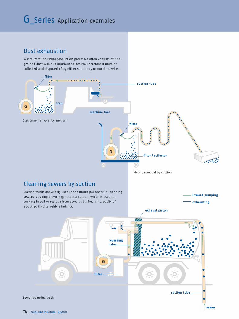
74 nash_elmo Industries G_Series
G_Series Application examples
G
G
G
Cleaning sewers by suction
Suction trucks are widely used in the municipal sector for cleaning
sewers. Gas ring blowers generate a vacuum which is used for
sucking in soil or residue from sewers at a free air capacity of
about 40 ft (plus vehicle height).
Dust exhaustion
Waste from industrial production processes often consists of fine-
grained dust which is injurious to health. Therefore it must be
collected and disposed of by either stationary or mobile devices.
exhaust piston
reversing
valve
sewer
suction tube
inward pumping
exhausting
filter
filter
filter
filter / collector
suction tube
machine tool
trap
Sewer pumping truck
Stationary removal by suction
Mobile removal by suction

nash_elmo Industries G_Series 75
G
Soil ventilation devices
Soil ventilation is used for soils that are unsaturated
with volatile substances. This method is recommended
for degassing BTX and LHKW contaminated soils.
The range of degassing apparatus depends on the
quantity, dissemination and saturation pressure of
the pollutant as well as on the air flow
in the subsoil.
Depending on conditions mentioned
above the range may vary between
33 and 262 ft. Exhaust air must be dis-
posed of according to pollution control
regulations (filtering, flaring etc.).
decontaminated
exhaust air
filter
saturated zone ground water
cover
Aeration of electroplating
baths
Air is blown through a perforated pipe into the
electroplating bath to improve intermixture.
In addition that air bubbles are kept off the
workpiece's surface.
G
workpieces
electroplating bath
Aeration of electroplating baths
Soil-ventilation
trap
unsaturated zone

76 nash_elmo Industries G_Series
Suction capacity
Power
Conversionfrom to°F °C t [°C] = t [°F] - 32
1.8
°C °F t [°F] = 1.8 · t [°C] + 32
Mass
Length
Temperature conversion
100% vacuum0 mbar
Atmospheric pressureapprox. 1013 mbar = 29,91inch Hg absolute
Total pressuredifference(gauge)
Total pressuredifference (vacuum)
Absolute pressure
PV-
5057
Annex
Beginning units Multiply by to get back conversion
atm 1.013 bar 0.987atm 1013.3 mbar 0.001atm 76. cm Hg 0.013atm 29.92 in Hg 0.033atm 1.033 kg/cm2 0.968mbar 0.0295 in Hg 33.86mbar 0.075 cm Hg 13.33mbar 100. Pa 0.01mbar 10.2 mm H2O 0.098mbar 0.4 in H2O 2.49mbar 0.015 PSI 68.97in Hg 13.6 in H2O 0.074in Hg 0.49 PSI 2.036in H2O 0.036 PSI 27.68
Beginning units Multiply by to get back conversion
m3/h 35.31 ft3/h 0.028m3/h 0.589 cfm 1.67m3/h 16.67 l/min 0.06m3/h 4.4 gal/min 0.227cfm 7.48 gal/min 0.134
Beginning units Multiply by to get back conversion
kW 1.34 hp 0.746kW 3415.2 BTU/h 0.0003BTU/h 0.0004 hp 2546.7
Beginning units Multiply by to get back conversion
in 2.54 cm 0.394in 0.083 feet 12cm 0.033 feet 30.48
Beginning units Multiply by to get back conversion
kg 2.2 lbs 0.454
Pressure
Types of pressure
■ Absolute pressure
The pressure measured from absolute zero, using ideal vacuum
as the datum. The measured pressure is always greater than the
reference pressure.
■ Total pressure difference, pressure
The pressure measured above the prevailing atmospheric pres
sure. The datum is the prevailing atmospheric pressure and the
measured pressure is always higher than the datum.
■ Total pressure difference, vacuum
The pressure measured lower than the prevailing atmospheric
pressure. The datum is the prevailing atmospheric pressure and
the measured pressure is always lower than the datum.
Conversion tables

Physical laws
nash_elmo Industries G_Series 77
Physical basics for blower applications
■ Symbols:
V Flow [cfm]
n Drive speed [rpm]
p Pressure [in Hg] or [PSI]
P Power [hp]
� Density [lbs/cu.ft.]
ta Temperature absolute [°F] (standard: 68+ 460=528 °F)
Index:
1 original (standard)
2 new
Examples
■ 1. Flow dependent on speed
A blower is operating at 3600 rpm and delivering 2000 cfm. If the
speed is reduced to 3000 rpm, what is the new flow?
■ 2. Pressure dependent on altitude
A blower is operating at an elevation of 5000 ft and is to deliver 3 PSI
pressure. What pressure blower is required by standard conditions?
29,92 in Hg barometric pressure sea level
24,89 in Hg barometric pressure at a 5000 feet-level
When a blower is to operate at a high altitude it is frequently specified
that the blower be capable of handling a given flow of standard condi-
tions. It is then necessary to determine the equivalent flow of air at the
higher altitude.
■ 3. A blower is to operate at 5000 ft altitude and is to handle 2000 cfm
of standard air. What is the flow of air the blower must handle at
5000 ft altitude?
Variable Volume Pressure Power
Speed change
Temperature change
Density change
V2= V1
n2
n1
p2= p1
n2
n1
2
p2= p1ta1
ta2
p2= p1
�2
�1
P2= P1
n2
n1
3
P2= P1
�2
�1
V2= V1 = 2000� 1667 cfm30003600
n2
n1
≈
V2= V1 = 2000� 2404 cfm29.9224.89
29.9224.89
≈
p2= 3� 3.6 PSI29.9224.89
≈

78 nash_elmo Industries G_Series
■ 4. Pressure dependent on the speed ratio
A blower is operating at a speed of 3600 rpm and delivering air
at 3 PSI pressure. If the speed is reduced to 3000 rpm, what is the
new pressure?
■ 5. Pressure dependent on the temperature
A blower is to handle 200 °F air at 3 PSI pressure. What pressure
(standard) blower is required?
A blower is capable of delivering 3PSI pressure with standard air.
What pressure will develop handling 200 °F inlet air?
■ 6. Power dependent of speed ratio
A blower is operating at a speed of 3600 rpm and requiring 10 hp.
If the speed is reduced to 3000 rpm, what is the new required
power?
Table for barometric pressure of various altitudes
The pressure values generated with the following formulae:
with p0 = pressure at your location.
In the table is p0 the standard air pressure 29.92 in Hg or 1,013 mbar
and feet = 0 the sea level.
Formulae in accordance to CINA (Comité International de Naviga-
tion Aérienne)
p2= p1 =3� = 3x0.83 2.08 PSI30003600
n2
n1
2 2
2≈
P2= P1 =10� = 10�0.83 5.78 hp30003600
n2
n1
3 3
3≈
p´[in Hg]= p0-29.92 [in Hg] 1- 288[K]-0.00198[K/ft]�h[ft]288 K
5.255
p´[hPa]= p0-1013.3 [hPa] 1- 288[K]-0.0065[K/m]�h[m]288 K
5.255
p2= p1 � =3� = 3.75 PSI660528
ta2
ta1
p1= p2 � =3� = 2.4 PSI528660
ta2
ta1
Altitude barom. pressure p´
feet m inch Hg PSI hPa=mbar
0 0 29.92 14.69 1.013100 30 29.81 14.64 1.010200 61 29.71 14.59 1.006300 91 29.60 14.53 1.002400 122 29.49 14.48 999500 152 29.39 14.43 995600 183 29.28 14.38 992700 213 29.17 14.32 988800 244 29.07 14.27 984900 274 28.96 14.22 981
1,000 305 28.86 14.17 9771,500 457 28.34 13.91 9602,000 610 27.82 13.66 9422,500 762 27.32 13.41 9253,000 914 26.82 13.17 9083,500 1,067 26.33 12.93 8914,000 1,219 25.84 12.69 8754,500 1,372 25.37 12.45 8595,000 1,524 24.90 12.22 8435,500 1,676 24.43 12.00 8276,000 1,829 23.98 11.77 8126,500 1,981 23.53 11.55 7977,000 2,134 23.09 11.34 7827,500 2,286 22.65 11.12 7678,000 2,438 22.22 10.91 7538,500 2,591 21.80 10.71 7389,000 2,743 21.39 10.50 7249,500 2,896 20.98 10.30 710
10,000 3,048 20.58 10.10 69710,500 3,200 20.18 9.91 68311,000 3,353 19.79 9.72 67011,500 3,505 19.40 9.53 65712,000 3,658 19.03 9.34 64412,500 3,810 18.66 9.16 63213,000 3,962 18.29 8.98 61913,500 4,115 17.93 8.80 60714,000 4,267 17.57 8.63 59514,500 4,420 17.23 8.46 58315,000 4,572 16.88 8.29 572
Barometric pressure of various altitudes
Annex

nash_elmo Industries G_Series 79
Qualified personnel
are persons who – on account of their training, experience, instruction, knowledge
of the appropriate standards, specifications, accident prevention regulations and the
operating environment – have been authorised by those responsible for plant safety
to perform the necessary work and at the same time to recognise and circumvent
potential hazards.
Knowledge of first aid and familiarity with the pertinent life-saving equipment are
also necessary.
The barring of unqualified personnel from work on heavy-current equipment is
regulated by DIN VDE 0105 or IEC 364.
For the sake of clarity, the operating instructions supplied with the equipment cannot
contain all the detailed information on possible design variants and in particular cannot
take into account every conceivable type of installation, operation or maintenance.
The operating instructions therefore basically contain only the information necessary to
enable qualified personnel (see above) to operate the machines or equipment correctly
in industrial applications.
In the event that the machines or equipment are intended for service outside of
industry, where more exacting demands may be placed on them (such as touch protec-
tion for children), the installation work must be supplemented by further protective
measures that are to be implemented locally.
Where clarifications are necessary, particularly with respect to lack of product-specific
detailed information, please contact the sales office concerned, quoting the type desi-
gnation and manufacturing number of the machine or equipment.
It is advisable to arrange for our service centres to take charge of the necessary
planning, installation, commissioning and after-sales service.
General safety information
NOTE:
The products in this catalogue
are used in the
■ capital goods industry
■ consumer goods industry
and in such sectors as
■ agriculture
■ the building industry and
■ allied trades.
This equipment has bare parts that are dangerous because they are live during operation;
in some cases these are moving or rotating parts. Such parts could cause severe injury
to persons and severe damage to property, for example in the event of unauthorised re-
moval of protective covers, improper use, wrong operation or insufficient maintenance.
The people in charge of safety must therefore guarantee that:
■ only qualified personnel are allowed to work on or around this equipment;
■ these persons have access at all times to the operating instructions supplied and
all other elements of the product documentation when working with the equipment,
and are obliged to systematically follow the instructions given therein;
■ unqualified personnel are not allowed to work on these machines or equipment or
in the vicinity thereof.

80 nash_elmo Industries G_Series
General delivery conditions
Export regulations
According to the current provisions (01/2003) of the German and US export regulations,
the products listed in this catalogue do not require any export permit. Export or re-export
is therefore allowed without the permission of the competent authorities unless the Order
on Foreign Trade lays down country-specific restrictions. This is subject to change. The
markings given on the delivery slip and invoice are the decisive criteria. An export permit
obligation may arise for specific countries as a result of the intended use of the products.
Unless otherwise stated on the individual pages of this catalogue, we reserve the right to
make changes, especially to the given values,dimensions and weights.
Illustrations are not binding. Our General Conditions of Trade and Delivery apply.
Trade marks
All product designations are trade marks or
product names of nash_elmo Industries or
other companies.
Responsible for the technical content
Dipl.-Ing. Lutz Kasimir
nash_elmo Industries GmbH
Corporate Communication
Fully automatic final check ofendshields of F_Series and G_Series drives.
Electronic check of the dimen-sional accuracy of a G_Series impeller.

nash_elmo Industries G_Series 81
Check of performance data andprinting of the test protocol.
Only quality has a future
Technical progress and market success are inseparable from the high quality of nash_elmo
products. To guarantee this high quality level, a reliable quality assurance system has been
established for monitoring all phases of production from development to delivery.
This quality assurance system meets the worldwide requirements, complies with the relevant
standards and specifications and fulfills the requirements of ISO 9001:2000.
This gives our customers the following advantages:
■ maximum operational safety;
■ high, consistent supply reliability;
■ compliance with the requirements of the European Market;
■ participation in national and international tenders.

82 nash_elmo Industries G_Series
ATEX information
Since July 1, 2003, it is compulsory by law within the European Union to design explosion-
proof machines according to ATEX 94/9 EG.
Free trade within the EC for ATEX compliant machines and devices are therefore guaranteed
due to European standardization of machine requirements. ATEX also includes non-electric
devices that are a potential ignition source.
A subdivision “Gas/particle(dust) explosion protection“ according to ATEX results through
the marking G (as)/D (ust). The „zones“ (according to RL 1999/92/EG) represent work areas
in which an explosive atmosphere1) can occur.
Depending upon the frequency and the duration of the appearance of the explosive atmos-
phere, ATEX subdivides different zones in which corresponding categories are assigned.
■ „Continuously or for longer periods of time“
Zone 0 (=G) und 20 (=D) Devices of category 1
■ „Occur occasionally“
Zone 1 (=G) und 21 (=D) Devices of category (1 or) 2
■ „Normally not likely to occur, or only for short periods of time“
Zone 2 (=G) und 22 (=D) Devices of category (1, 2 or) 3
Our G_200 and G_400 ranges of gas ring compressors are produced according to the ATEX
requirements. Machines in the EEx version have been discontinued and replaced by machi-
nes corresponding to the new directive, category 3.
There is an ATEX version of every housing size of the G_200 range available in category 3D,
3G, 3/2D and 3/2G2). The side channel blowers comply with the temperature class T3 with a
max. (surface) temperature of 125°C and correspond to the protection class IP55. For the
category 3/2D, the blowers correspond to the protection class IP65..
All ATEX machines of the G_200 series are available for the categories 3D, 3G and 3/2D as
fixed voltage machines for 50 and 60 Hz. For the category 3/2G, only a pure 50-Hz version
is available.
1) Mixture of air (oxygen) and flammable gases, steam, powder.
2) 3/2 means: Category 3 inside, Category 2 outside

nash_elmo Industries G_Series 83
Footnotes:
1) Measuring surface sound-pressure level acc. toEN 216801, measured at a distance of 1 m. Thepump is throttled to a medium inlet pressure,a hose is connected to the discharge side, anda vacuum-relief valve is not fitted.
2) For selection and ordering information, seeaccessories. The pressure limits of the valvesare based on a cooling agent and ambienttemperature of 25 °C.
3) For 2BH1 943, only mounting on the end-casingis possible.
4) Tolerances: the motors comply with DIN EN60 034/DIN IEC 34-1 and Insulation Class F:TThhrreeee--pphhaassee::fixed voltages incl. ATEX ± 10%voltage range ± 5 %in compliance with UL and CSA - 10% /+ 6 %(UL 507 u. CSA 22.2 No. 113)SSiinnggllee--pphhaassee::
Fixed voltages: ± 5 %If during continuous operation only 90% ofthe maximum end pressure is used, theadmissible tolerance increases to ± 10 %.In compliance with UL and CSA - 10 % /+ 6 %(UL 507 u. CSA 22.2 No. 113)FFrreeqquueennccyy:: ± 2 %The motors comply with the IEC and Europeannorms quoted. The European norms replacethe national norms of the following memberstates: Germany (VDE), France (NF C), Belgium(NBNC), Great Britain (BS), Italy (CEI), Nether-lands (NEN), Sweden (SS), Switzerland (SEV)and others.The machines also comply with various natio-nal norms.The following norms have been adapted tothe publications IEC 60 034-1 and the motorscan be used at standard rated performance:
UL 507 USACSA 22.2, No. 113 CanadaIS 325 IndiaIS 4722NEK_IEC 60034-1 Norway
Specification of voltagein order number: ▲ ▲
2BH1 ...-..c .c
3-phase
185-225 V ∆ / 320-390 V Y H 1 CUL US200-240 V ∆ / 345-415 V Y H 6 CUL US345-415 V ∆ H 7 CUL US
-500-V ∆ C 5 CUL US
1-phase
100/200 V V 4 CUL US115/230 V V 5 CUL US
/230 V A 1
Voltages at 60 Hz 4)
3-phase
200-240 V ∆ / 345-415 V Y H 1 CUL US220-275 V ∆ / 380-480 V Y H 6 CUL US 380-480 V ∆ H 7 CUL US
-575 V ∆ C 5 CUL US
1-phase
100/200 V V 4 CUL US115/230 V V 5 CUL US
/115 V B 6/230 V B 8
Voltages 3-phase ATEX 4)
50 Hz, categories 3D, 3G, 3/2D
230 V ∆ / 400 V Y D 1500 V ∆ D 5400 V ∆ / 690 V Y D 6
50 Hz, category 3/2G
230 V ∆ / 400 V Y D 1500 V ∆ D 5400 V ∆ / 690 V Y D 6
60 Hz, categories 3D, 3G, 3/2D
460 V ∆ D 1575 V ∆ D 5460 V Y D 6
60 Hz, category 3/2G
440 V Y G 1575 V ∆ G 5440 V ∆ G 6
Voltages at 50 Hz 4)
Other voltages available upon request
G_Series Voltage Overview

HEN
NIG
· N
bg
European Headquarters
Nürnberg, Germany
Katzwanger Straße 150 D-90461 NürnbergTel.: +49 911 1454 0
Order-No: VNE:C-CA001-A2a-AM
Printed in GermanyDispo 27801 NE 2238/059 pdf / 01-2005© 2004 All Rights Reserved
nash_elmo Industries
www.nash-elmo.com
Corporate Headquarters
Trumbull, CT USA
9 Trefoil DriveTrumbull, CT06611-1330Tel.: +1 800 553 6274
Our product range
L_Series Liquid ring vacuum pumps and compressors
■ Chemical and petrochemical
industry
■ Process engineering
■ Paper and pulp industry
■ Power plants
■ Plastics industry
■ Medical technology
■ Food industry
■ General mechanical engineering
D_Series Dry pumps
■ Chemical and pharmaceutical
industry
■ Process engineering
■ Metallurgy
■ Packaging industry
■ Food industry
V_Series Vane pumps
■ Chemical and petrochemical
industry
■ Food processing industry
■ Packaging
■ General mechanical
engineering
F_Series Radial Fans
■ Plastics industry
■ Printing industry
■ Glass industry
■ Industrial furnaces
■ Industrial vacuums
S_Series Standardized systems
■ Chemical industry
■ Process industry
■ Food processing industry
■ Packaging
■ Power generation and supply
correction level: A2a/2005