g series industrial barcode printer ’s manual€¦ · g series industrial barcode printer...
TRANSCRIPT

I
Argox website: http://www.argox.com
G Series Industrial Barcode Printer User’s Manual

II
Table of Contents
1. Checking Your Box 5
Unpacking 5 Connecting the Power Cord 7 Parts and Features 9 Loading Ribbon 12 Loading Media 16
Standard Mode 16 Peel Off Mode 20 Cutter Mode 24
Adjust Position of Label Sensor 27
2. Printer Operation 28
Front Panel 28 LED Indicators 29 Buttons 30 LCD Display 32 Changing Settings from the Panel 33 Setting Display Language 37
Rear Panel 38 DIP switch 39
Media Calibration 40 Printing a Configuration Report 41 Resetting to Factory Default Settings 42
3. Computer Connections 43
Connecting the Printer 43 Communicating with the Printer 44 Installing a Printer Driver 45
4. Troubleshooting 52
LED and LCD Diagnosis 52

III
Media Problems 52 Ribbon Problems 53 Other Problems 53
Printer Status 55 Transmission Problems 56 Recovery 56 Printer Maintenance 57 Cleaning the Print Head 58
Cleaning Interval 58 Cleaning Material 58 Cleaning Direction 59
Cleaning the Roller 59 Cleaning the Media Compartment 59
5. Technical Reference 60
General Specifications 60 Fonts, Bar Codes and Graphics Specification 63
Printer Programming Language A, PPLA 63 Interface Specifications 64
Serial Interface 64 Connection with Host 65 Parallel (Centronics) 67
Auto Polling 67 ASCII TABLE 68
6. Accessory 69
Cutter Installation 69 Dispenser & Rewinder Installation 74

4
Proprietary Statement
This manual contains proprietary information of Argox Information
Co., Ltd. It is intended solely for the information and use of parties
operating and maintaining the equipment described herein. Such
proprietary information may not be used, reproduced, or disclosed
to any other parties for any other purpose without the expressed
written permission of Argox Information Co., Ltd.
CAUTION:
Any changes or modifications not expressly approved by the party
responsible for compliance could void the user's authority to
operate the equipment.

5
1. Checking Your Box
Unpacking
After receiving your printer, please check for possible shipping
damage:
1. Inspect the outside of both the box and the printer for
possible damage.
2. Open the top cover of the printer to see if the media
compartments are in order.
Note: If damage has occurred, contact your shipping company
immediately to file a claim.
3. Check whether you have received the following
accessories together with the printer. If there are any
items missing, please contact your local dealer.

6
Package Contents Printer Power Cord
Quick Guide
CD Rom (including software and
user’s manuals)
Core for Ribbon
USB to Centronics
Cable
7
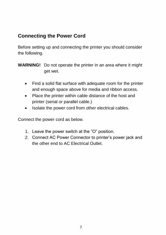
Connecting the Power Cord
Before setting up and connecting the printer you should consider
the following.
WARNING! Do not operate the printer in an area where it might
get wet.
Find a solid flat surface with adequate room for the printer
and enough space above for media and ribbon access.
Place the printer within cable distance of the host and
printer (serial or parallel cable.)
Isolate the power cord from other electrical cables.
Connect the power cord as below.
1. Leave the power switch at the ”O” position.
2. Connect AC Power Connector to printer’s power jack and
the other end to AC Electrical Outlet.

8
Power Switch
AC Power
Connector
Power Jack
AC Electrical Outlet

9
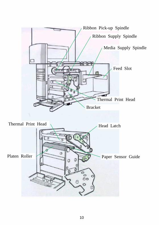
Parts and Features
Top Access Door
LCD Display
Front Access Door
10
Ribbon Pick-up Spindle
Ribbon Supply Spindle
Media Supply Spindle
Feed Slot
Thermal Print Head
Bracket
Head Latch
Paper Sensor Guide Platen Roller
Thermal Print Head

11

12
Loading Ribbon
Notes:
1. This section is applicable to transfer thermal printing.
2. Attached ribbon is with coated side in.
1. Lift the top access door and the front access door to expose the
compartment. ( Figure 1 )
2. Push the head latch by anti-clockwise, and then fold the
bracket. ( Figure 2 )
3. Unwrap the ribbon roll pack and separate the ribbon roll and
the bare core.
4. Insert the ribbon roll into the ribbon supply spindle. ( Figure 3 )
5. Lead the bare core through the print head module. ( Figure 4 )
6. Attach the edge of the ribbon on the bare core and wind it a
little bit onto the core.
Note:
The coated side of the ribbon should be faced down.
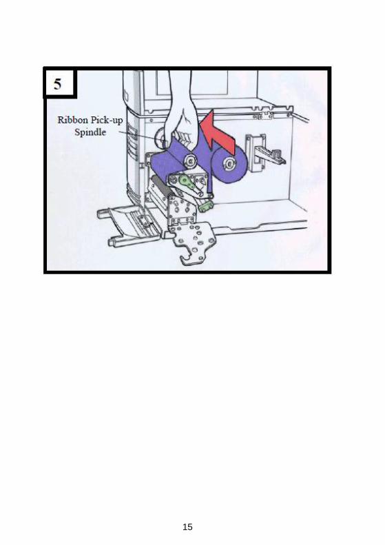
7. Insert the bare core into the ribbon pick-up spindle. ( Figure 5 )
8. Turn the pick-up spindle to ensure the ribbon is tightly wound.

13

14
15

16
Loading Media
G-6000 printer can be operated in three different options:
standard, peel-off, or with a cutter.
■ Standard mode allows you to collect each label freely.
■ In peel-off mode, the backing material is being peeled away
from the label as it is printed. After the former label is removed,
the next one will be printed.
■ In cutter mode, the printer automatically cuts the label after it
is printed.
Standard Mode
1. Insert the media roll into the media supply spindle and move
the media guide to the inside. ( Figure 6 )
2. Push the head latch by anti-clockwise, and then fold the
bracket. ( Figure 7 )
3. Remove the outside media guide. ( Figure 8 )
4. Lead the Media through the print head module and under the
paper sensor guide.
5. Put back the outside media guide, close the bracket, and
buckle the head latch. ( Figure 9 )
6. Close the top access door and the front access door and then
turn on the printer or press the “FEED” button if the printer is
already on ( Figure 10 )

17

18

19
10

20
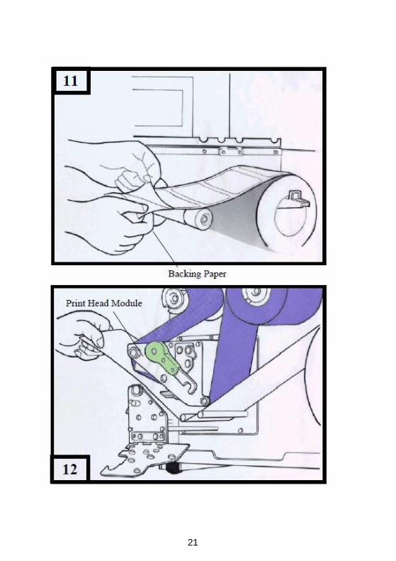
Peel Off Mode
Follow the common procedure of “ Loading Media “ of Standard
Mode from step 1 to 3.
4. Remove approximately 6” long labels from the label backing
paper ( Figure 11 )
5. Lead the backing paper through the print head module.
( Figure 12 )
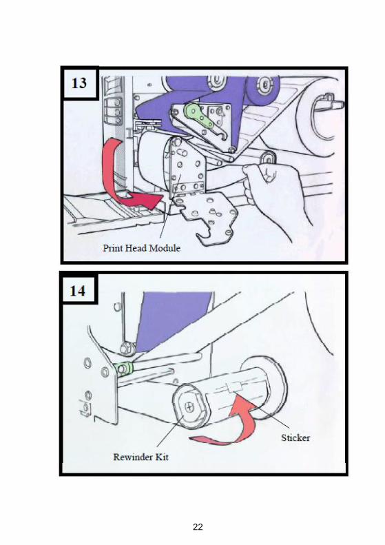
6. Turn back under the print head module. ( Figure 13 )
7. Use a sticker to fix the media on the rewinder kit.( Figure 14 )
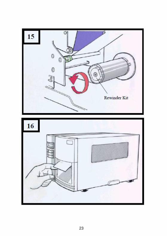
8. Turn the rewinder kit twice to ensure the media is firmly fixed.
( Figure 15 )
9. Close the side access door and turn on the printer or press the
FEED button if the printer is already on. ( Figure 16 )
Note:
1. The “ FEED “ button will not drive the printer to peel. The
peeling work can be executed only when (1 ) the software
setting is ready; (2) Bit 5 of DIP switch at real panel must be
set to ON position.
2. Please sure the peeler sensor is out of ribbon path when it’s
installed.
21
22
23

24
Cutter Mode
Follow the common procedure of “ Loading Media “ of Standard
Mode from step 1 to 3.
4. Insert the media into the print head module and under the
paper sensor guide. ( Figure 17 )
5. Put back the outside media guide, close the bracket, and
buckle the head latch. ( Figure 18 )
6. Close the top access door and turn on the printer or press the
FEED button if the printer is already on, and then the label will
be fed into the cutter mode automatically. ( Figure 19 )
Note: The “ FEED “ button will not drive the printer to cut. The
cutting work can be executed only when (1) the software
setting is ready; (2) Bit 3 of DIP switch at rear panel must be
set to the ON position.

25

26
27
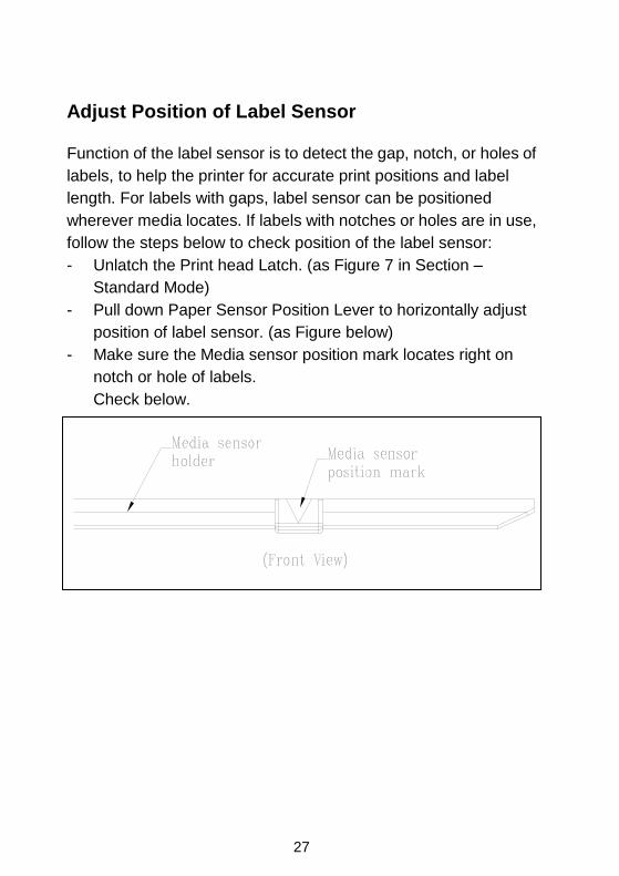
Adjust Position of Label Sensor
Function of the label sensor is to detect the gap, notch, or holes of
labels, to help the printer for accurate print positions and label
length. For labels with gaps, label sensor can be positioned
wherever media locates. If labels with notches or holes are in use,
follow the steps below to check position of the label sensor:
- Unlatch the Print head Latch. (as Figure 7 in Section –
Standard Mode)
- Pull down Paper Sensor Position Lever to horizontally adjust
position of label sensor. (as Figure below)
- Make sure the Media sensor position mark locates right on
notch or hole of labels.
Check below.

28
2. Printer Operation
The illustrations below describe parts and features.
Front Panel
The front panel includes:
3 LED indicators (READY, MEDIA and RIBBON)
3 buttons (FEED, PAUSE and CANCEL)
LCD display
Top Access Door
Front Access Door
Top Access Door
Front Access Door
LEDs and
Buttons
LCD Display

29
LED Indicators
There are three LED indicators on the front panel, “READY”,
“MEDIA” and “RIBBON”. These indicators display the operation
status of the printer.
LED Function
READY The READY indicator will remain lighted except if
any of the following conditions happens
- The printer is at PAUSE status.
- Error condition.
MEDIA The MEDIA indicator will remain on for the normal
operation of the printer.
Blinking – Media is used out.
RIBBON ON – under thermal transfer mode with ribbon
installed. Bit 1 of DIP switch is at ON position.
OFF – under direct thermal mode. ( no ribbon
installed ) Bit 1 of DIP switch is at OFF position.
Blinking – Ribbon is used out.
30
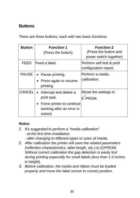
Buttons
There are three buttons, each with two basic functions.
Button Function 1
(Press the button)
Function 2 (Press the button and
power switch together)
FEED Feed a label. Perform self test & print
configuration report.
PAUSE Pause printing.
Press again to resume
printing.
Perform a media
calibration.
CANCEL Interrupt and delete a
print task.
Force printer to continue
working after an error is
solved.
Reset the settings in
E2
PROM.
Notes:
1. It’s suggested to perform a “media calibration”
- at the first time installation.
- after changing to different types or sizes of media.
2. After calibration the printer will save the related parameters
(reflection characteristics, label length, etc.) to E2PROM.
Without correct calibration the gap detection is easily lost
during printing especially for small labels (less than 1.5 inches
in height).
3. Before calibration, the media and ribbon must be loaded
properly and move the label sensor to correct position.

31
4. After self-test, the printer is at dump mode, If you need normal
operation, you must press CANCEL to restart the printer.

32
LCD Display
The model G-6000 is equipped with a LCD that displays:
printer status
printer settings
After power-on, the LCD displays the following message as
examples:
The first parameter, 203, which stands for the printer
resolution. The second parameter indicates the emulation
(printer language), PPLA.
If any abnormal condition occurs the related message will be
displayed. For example:
READY (203,PPLA)
RIBBON OUT

33
Changing Settings from the Panel
You may change settings, by using the buttons on the front panel,
instead of changing settings via software or commands.
Buttons Function
PAUSE+CANCEL
Press to enter setting mode.
(Don’t press over 1 second)
Press again to exit setting mode and return
to normal mode.
FEED Press to show next parameter.
PAUSE Press to show next setting item.
CANCEL Select and save a parameter to permanent
memory (E2
PROM).
The parameter will be kept even if you
restart the printer, until it’s changed again by
either panel or commands.
Note: Do not change settings during printing or sending printing
data.
34
Procedure: Turn on the printer first. 1. Till “ READY” message is displayed on the LCD, press
[PAUSE]+[CANCEL] buttons simultaneously.
2. Press [PAUSE] button for several times to select the proper item that you want to change the parameter.
3. Press [FEED] button till the specified parameter appears.
4. Press [CANCEL] button to save it. A “*” mark will appear at the last column.
5. Press both [PAUSE] and [CANCEL] buttons at the same time, to return to normal mode.

35
Printer LCD function settings and parameters:
Item Range Factory
Default
Remarks
CUT/PEEL POS (mm)
-15 ~ 15 mm 0 mm Controls cut and peeling position.
PRINT OFFSET (mm)
-8 ~ 15 mm 0 mm Controls vertical print position. Positive value only.
TPH VER OFFS (mm)
-3 ~ 3 mm 0 mm Offset of vertical print position.
RECOVERY PRINT
ENABLED, DISABLED
ENABLED Contents reprint after media-out or ribbon-out.
WIN CON LEN (mm)
0 ~ 254 mm 0 mm This takes effect only when you install under Windows with bundled printer driver and use continuous media.
COUNTER ON LCD
ENABLED, DISABLED
ENABLED
MEDIA SENS. TYPE
REFLECTIVE SEE-THROUGH
REFLECTIVE Select the proper type by the media characteristics. Once you change it, make sure to make calibration before printing.
BACK FEED DISABLED, ENABLED
DISABLED
BACK DISTANCE (mm)
10~40 mm 0 mm This item appears only when BACKFEED is

36
enabled.
BASE DARKNESS
0 mm
Notes: 1. To make sure the settings take effect you had better restart the printer after changing them. 2. When you store graphics with compression in flash board, do not use them under non-compression mode. They must be consistent. 3. Before selecting the see-through sensor make sure the main board version is 5.0 or later, otherwise it cannot work.

37
Setting Display Language
The printer supports six languages, English, French, German, Italian, Spanish and Portuguese for LCD display. To select the language 1. Press PAUSE and CANCEL buttons at the same time. 2. Hold both buttons for about 3 seconds. 3. Release buttons. 4. The language item will appear:
5. Press FEED button for next language. 6. Press CANCEL button to select or set the language for
your need. Pressing PAUSE or PAUSE+CANCEL buttons exits setting and enters normal mode.
Item Range Factory Default
LANGUAGE ENGLISH, FRENCH, GERMAN, ITALIAN, SPANISH, PORTUGUESE
ENGLISH
LANGUAGE
ENGLISH
*

38
Rear Panel The rear panel includes:
-An 8-bit DIP switch - A 36-pin Centronics parallel port - A 9-pin RS-232 serial port - A PS/2 keyboard interface - A power switch and a power connector

39
DIP switch
You may configure the printer by setting DIP switches. Once the setting is changed, please restart the printer by turning the power OFF then turn ON again.
Switch No.
Position
ON OFF Function
1
ON Thermal transfer printing mode. Ribbon detection is enabled.
OFF Direct printing mode. Ribbon detection is disabled.
2 ON Alternate (printable) control code set.
OFF Standard control code set.
3 ON Cutter is installed.
OFF Cutter is not installed.
4 ON The media gap height is more than 4mm.
OFF Media with normal gap or continuous paper
5 ON Dispenser is installed.
OFF Dispenser is not installed.
6, 7, 8
OFF, OFF, OFF Serial port speed = 9600 bps
ON, OFF, OFF Serial port speed = 2400 bps
OFF, ON, OFF Serial port speed = 4800 bps
ON, ON, OFF Serial port speed = 19200 bps
OFF, OFF, ON Serial port speed = 38400 bps
ON, ON, ON Serial port speed = 9600 bps and for bar code reader.

40
Media Calibration
After the first time of installation, the printer media is changed or
the media sensor board is replaced, the media sensor calibration
must be performed.
1. Load the media (and ribbon for thermal transfer printing)
properly.
2. Shift the media sensor to proper position.
3. Press and hold PAUSE/CALIBR. button then turn on the
power switch.
4. When “CALIBRATION…” is displayed on the LCD, release
the FEED button.
During media calibration, a few inches of media will be fed out.
The READY and MEDIA indicators will blink for few seconds
during calibration is proceeding. Without the proper
calibration, the gap detection will not stable especially for the
small label (less than 2.0 inches in height).
After the calibration, all the related parameters will be stored in
the EEPROM of main board.
Note:
After the first time of installing the media or the media type is
changed, this procedure must be carried out. Failing to do it, the
media-empty and media-gap detection might be incorrect.

41
Printing a Configuration Report
To perform a self-test and print a configuration report, helping to
check printer’s print quality and internal settings. Steps as below:
1. Turn off the printer.
2. Load media and ribbon.
3. Press and hold the FEED button while turning on the
power.
4. When “SELF-TESTING …” is displayed on the LCD,
release the FEED button.
5. The printer now prints out a configuration report.
6. Finally the “READY” message is displayed and the
READY indicator stops blinking and lights up.
The following information will be printed on this report.
- Font list
- DIP switch settings
- Hardware configuration and status
- Label parameters
- Firmware version
Note:
After self test the printer will enter character dump mode. For
normal operation press the CANCEL button to stop dump mode.

42
Resetting to Factory Default Settings
If you would like to reset the printer to its factory defaults after
certain commands have been sent or settings changed:
1. Turn off the printer.
2. Press and hold the CANCEL button, and turn on the
power.
3. When the message “ E2PROM RESET…” is displayed on
the LCD and READY indicator blinks, release the button.
4. Finally the “READY” message is displayed and the
READY indicator stops blinking and lights up.
5. The following parameters automatically reset.
- Label parameters
- Heat (Darkness)
- Speed
- Symbol set (language)
- Others for specific emulation
Notes:
1. All settings stored in non-volatile E2PROM cannot be
destroyed even by turning the printer off.
2. The settings of DIP switch cannot be reset.
3. It is necessary to perform label sensitivity calibration after
resetting.
4. The printed label count cannot be reset.

43
3. Computer Connections
The printer comes with a standard Centronics parallel interface,
and a nine-pin Electronics Industries Association (EIA) RS-232
serial data interface.
Connecting the Printer
1. You can connect the printer with any standard Centronics
cable to the parallel port of the host computer.
2. Alternatively you can connect the printer with a serial cable to
the RS232C port of your computer or terminal. (for PC
compatibles, the RS232C port is COM1, COM2 or COM3.)
Note:
Using Centronics allows for a much higher communication
speed than the use of a serial.
44
Communicating with the Printer
The bundled printer driver can be applied to all applications under
Windows XP/ Vista/ Windows 7/ Windows 8, supporting 32-bit/
64-bit operation systems. With this driver you can operate any
popular Windows software applications including Argox Bartender
UL label editing software or MS Word, etc., to print to this printer.
The following installation steps are based on G-6000 as an example. The screens included for these steps are taken from Windows XP; steps in other versions of operation systems are similar. Drivers can be installed via the CD-Rom included in printer package; or it can be downloaded from Argox website >> Technical Support >> Download Center >> select product model to access: http://www.argox.com/content.php?sno=0000033

45
Installing a Printer Driver
1. Turn off the printer. Plug the power cable into the power
socket on the wall, and then connect the other end of the
cable to printer's power socket. Connect the Parallel cable,
Serial cable, or Ethernet cable to the proper port on the printer
and on your computer.
2. Prepare the documentation and software CD-Rom from
printer package and then install to CD-Rom drive of your
computer. The CD-Rom will bring out the following prompt.
Click “Go”:

46
3. Choose Industrial Barcode Printers on the screen, go to
G-6000 product page, click on version of Seagull driver and
then start installation:
47
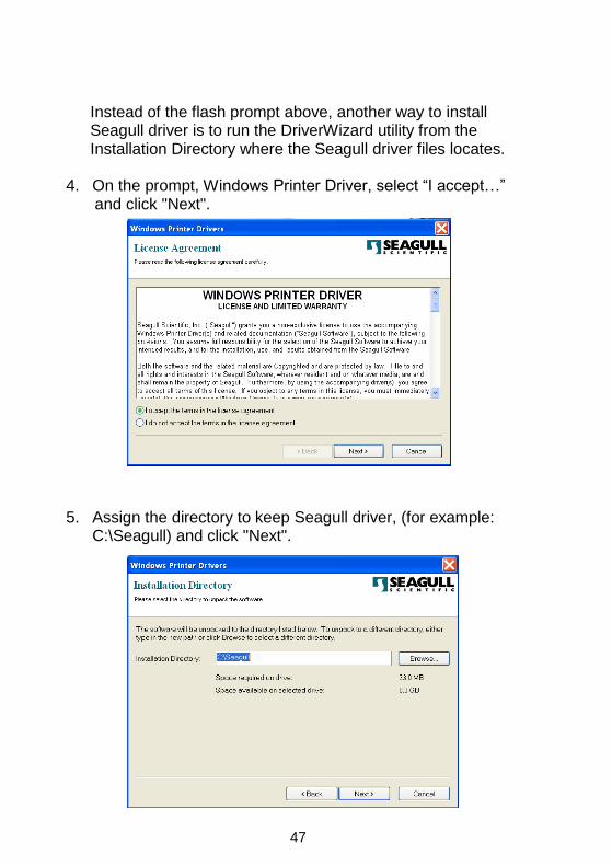
Instead of the flash prompt above, another way to install Seagull driver is to run the DriverWizard utility from the Installation Directory where the Seagull driver files locates.
4. On the prompt, Windows Printer Driver, select “I accept…” and click "Next".
5. Assign the directory to keep Seagull driver, (for example:
C:\Seagull) and click "Next".

48
6. Click "Finish". 7. Select Install printer drivers and Click "Next"

49
8. Select model & emulation – G-6000 PPLA:
9. Select the port of the printer and click "Next".
Argox G-6000 PPLA

50
10. Enter Printer name (i.e. Argox G-6000 PPLA) and select
"do not share this printer”, and click "Next".
11. Check all the data on the showing screen, if it is correct, click
"Finish".
Argox X-1000VL PPLB
Argox G-6000 PPLA
Argox G-6000 PPLA
Argox G-6000 PPLA
51
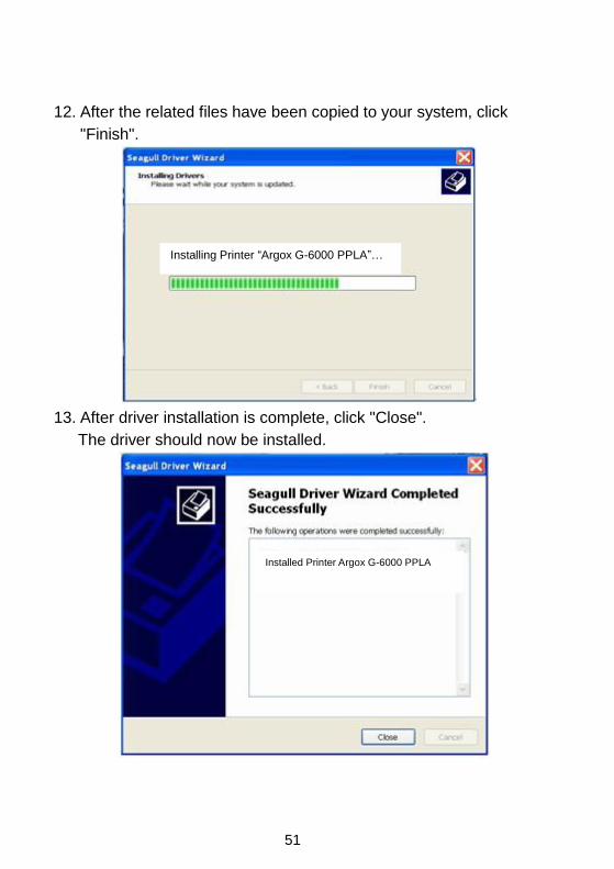
12. After the related files have been copied to your system, click
"Finish".
13. After driver installation is complete, click "Close".
The driver should now be installed.
Installing Printer “Argox G-6000 PPLA”…
Installed Printer Argox G-6000 PPLA

52
4. Troubleshooting
Normally, if the printer is in not working properly, the "READY" LED
blinks continuously, and printing and communication between the
host and printer stops.
LED and LCD Diagnosis
Blinking LEDs indicate a problem. Check the LEDs and the LCD
display and refer to the following solutions:
Media Problems
LED/LCD Indication
READY and MEDIA LEDs Blinking
LCD Display MEDIA OUT
Possible Problems Solutions Remarks
Miss-detected gap
Check the media
path.
Check the position of
the label sensor.
For continuous
media, check
application and
driver, and select
continuous media.
Media out Supply the media roll
Media not installed Install the media roll
Media jam Recover the jam
Note: If problem continues perform a label sensor calibration.

53
Ribbon Problems
LED/LCD Indication
READY and RIBBON LEDs Blinking
LCD Display RIBBON OUT
Possible Problems Solutions Remarks
Ribbon out Supply the ribbon roll Not applicable to
direct thermal.
Ribbon jam Recover the jam
Ribbon sensor error Replace ribbon sensor
Note: If you use direct thermal, set bit 1 of DIP switch to OFF.
Other Problems
LED Indication
READY LED Blinking
Problems Solutions Remarks
Serial IO error Inconsistent baud rate,
format or protocol
between host and printer
Check bits 6 ~ 8 of DIP
switch. Refer to section 2
for DIP switch.
Not for Centronics

54
Cutter failed Check the media.
Check the connection
between cutter and main
board.
Call for service.
DIP switch bit 3
should be ON for
cutter.
Memory full Check the graphics and
soft fonts from host.
Make sure to delete the
graphics and soft fonts if
they are no longer used
by the application
software.
(Refer to the Technical
Manual for details).
Note: After problem is solved, press CANCEL button to continue
printing.

55
Printer Status
LCD Display Blinking
LED
Description
PAUSE READY Printer is paused. Press PAUSE or
CANCEL to return to normal operation
mode.
MEDIA OUT MEDIA
READY
Media is uninstalled or used up. Load new
media to the printer.
RIBBON OUT RIBBON
READY
Ribbon is uninstalled or end-of-ribbon
occurred. Load new ribbon to the printer.
If you print in direct thermal mode, printing
without ribbon, set bit 1 of DIP Switch to
“OFF” position.
SERIAL IO
ERROR
READY Format or baud rate of RS232
communication is inconsistent between
printer and host.
CUTTER FAILED READY Cutter cannot cut off the media, check
media and cutter.
MEMORY FULL READY Printer buffer full due to loaded soft fonts,
graphics or forms. Check data format. Call
for service.
HEAD OPEN READY Print head latch is not closed. To make
printer print labels normally, the head latch
must be closed.
P. SENSOR O.R. READY Media sensor is out of detection range
during calibration. Make sure media is
installed and the label sensor locates under
media properly.

56
Transmission Problems
If the host shows "Printer Time out"
1. Check if the communication cable (parallel or serial) is
connected securely to your parallel or serial port on the PC
and to the connector on the printer at the other end.
2. Check if the printer power is turned on.
If the data has been sent, but there is no output from the printer.
Check the active printer driver, and see if Seagull Driver for your
Windows system and the label printer has been selected.
Recovery
After correcting problems, simply press the CANCEL button or
restart the printer. Make sure the LEDs are not blinking and
remember to resend your files.

57
Printer Maintenance
Vertical streaks in the printout usually indicate a dirty or faulty print
head. (Refer to the following examples.) Clean the print head. If the
problem persists, replace the print head.
For unstable ribbon roll rotation, check the label path and make
sure the head latch is securely closed.
Poor printout quality:
The ribbon may not be qualified.
The media may not be qualified.
Adjust the Darkness (heat temperature).
Slow down the print speed.
Refer to the following and clean the related spare parts.

58
Cleaning the Print Head
To keep the Print Head remain in the best conditions and efficiency
and to extend duration for use, regular cleaning action is needed.
Note: Turn off the printer before cleaning.
Clean the print head as follows:
1. Turn off the printer.
2. Open the top cover to access the print head module
3. Remove the ribbon.
4. Rub the print head with a cotton bud moistened with
“Ethanol” or “IPA”.
5. Check for any traces of black coloring or adhesive on the
cotton after cleaning.
6. Repeat if necessary until the cotton is clean after it is
passed over the head.
Cleaning Interval
It’s strongly recommended to regularly clean print heads at least
when changing every one label roll (in direct thermal printing mode)
or every one ribbon roll (in thermal transfer printing mode). In
addition, if printers are operated under critical applications and
environments, or if it’s found that print quality is degraded, please
clean print heads more frequently.
Cleaning Material
Surface of print head’s heating element is very fragile. To prevent
from any possible damage, please use soft cloth/ cotton buds with
“Ethanol” or “IPA” to clean print head surface.
59
It’s strongly recommended to wear hand gloves during cleaning
progress.
Do not touch print head surface by bare hands or with any hard
equipment.
Water or spit should be kept away in case of corrosion on heating
elements.
Cleaning Direction
When cleaning the print head, always wipe in One-Way Direction -
from Left to Right only, or, from Right to Left only, to clean “Heating
Line” of print head gently without excessive stress.
Do not wipe back and forth, to avoid dust or dirt on cleaning cotton
would be attached onto print head again.
Special Caution:
Warranty of print heads will be void if print head serial number is
removed, altered, defected, or made illegible, under every
circumstance.
Cleaning the Roller Using a cotton bud moistened with alcohol, clean the roll and
remove any attached glue.
Note: Clean the roller after it has been in contact with foreign
materials such as dust or adhesives.
Cleaning the Media Compartment Clean the media compartment with a cotton bud that has been
moistened with a mild detergent. Every time a media roll is printed,
you should clean this compartment to reduce the incidence dust.

60
5. Technical Reference General Specifications G-6000
Printing
Method Direct Thermal / Thermal Transfer
Printing
Resolution 203 dpi (8 dots/mm)
Printing
Width Max 6.6” (168mm)
Printing
Length Max. 30” (7620 mm)
Printing
Speed 2 ~ 6 IPS (51~152 mm/s)
Memory 2MB DRAM, 1MB Flash ROM
CPU Type 32 bit RISC CPU
Sensors
Media gap & black line Reflective sensor x 1
(movable) & Transmissive sensor x 1 (movable),
Head open switch, Ribbon end sensor
Display &
Operation
Interface
LED indicator x 3,
Back-lit LCD Display 16 x 2-line (multilingual),
Button x 3
(Feed(Config.)/Pause(Calibr.)/Cancel(Reset))
Communicati
on interfaces Centronics parallel, RS-232 serial

61
Media Type
Roll-feed, die-cut, continuous, fan-fold, tags,
ticket in thermal paper or plain paper, fabric
labels
Media
Max Width: 6.3”(160mm)
Min Width:1”(25.4mm)
Thickness: 0.0025”~0.01”(0.0635~0.254mm)
Max roll capacity(OD): 8”(203mm)
Core size: 1.5” ~ 3” (38~76mm) ID
Ribbon
Ribbon Width: 1”~6.1”
Ribbon roll – max OD: 2.5”(63mm)
Ribbon Length: max 360m
Core size – ID: 1”(25.4mm)
Wax, Wax/Resin, Resin
(Ribbon Wound Ink-side in)
Dimension W 310mm x L 445mm x H 260mm
Weight 32lbs(14.5kgs)
Power
Source
Internal Universal Power Supply
100 ~ 240 VAC, 2.5A, 50/60 Hz
Operation
Environment
Operating Temperature 40 F~100F
(4C~38C), 10% ~ 90% non-condensing,
Storage Temperature -4F~122F (-20C~50C)
Driver
Operating
Systems
Win XP/ Vista/ Windows 7/ Windows 8
Printer
Languages PPLA

62
Options and
Accessories
Cutter, Dispenser Kit, RTC Card, 2MB Asian
Font Card(Traditional Chinese, Simplified
Chinese, Korean and Japanese), ArgoKee
Agency
Listing CE, cULus, FCC class A, CCC, RoHS
Note:
Since Font Card and optional RTC Card share the same slot on
G-6000 main board, they cannot be used at the same time.

63
Fonts, Bar Codes and Graphics Specification
The specifications of fonts, bar codes and graphics depends on the
printer emulation. The emulation is a printer programming language
through which the host can communicate with your printer.
Printer Programming Language A, PPLA
Specification G-6000
Font Types
Courier (including PC Set, Legal, ECMA94 and Roman-8), 7 alpha-numeric fonts, OCR-A/B, ASD smooth font.
Soft fonts are downloadable.
Font Expandability 1x1 to 24x24
Character Rotation 0, 90, 180, 270 degree, 4 direction rotation
1D Bar Code Types
Code 39, UPC-A, UPC-E, Code 128 subset A/B/C, EAN-13, EAN-8, HBIC, Codabar, Plessey, UPC2, UPC5, Code 93, Postnet, UCC/EAN-128, UCC/EAN-128 K-MART, UCC/EAN-128 Random Weight, Telepen, FIM, Interleave 2 of 5 (Standard/with modulo 10 checksum/with human readable check digit/with modulo 10 checksum & shipping bearer bars), GS1 Data bar (RSS)
2D Bar Code Types
MaxiCode, PDF417, Data Matrix (ECC 200 only), QR code, Composite Codes, Aztec Barcode, Micro PDF417
Graphics PCX, BMP, IMG, GDI and HEX format files

64
Interface Specifications
This section presents the interface specifications of IO ports for the
printer. These include pin assignments, protocols and detailed
information about how to properly interface your printer with your
host or terminal.
Serial Interface
The RS-232 connector on the printer side is a female, DB-9.
Pin Signal Description
1 No function Shorted to Pin - 6
2 Received Data, RxD
Input. Serial “Received Data”
3 Transmitted Data, TxD
Output. Serial “Transmitted Data”.
4 No function No connection
5 GND Signal Ground
6 No function Shorted to Pin - 1
7 Request to Send, RTS
Output. Used as the control signal for “H/W Flow Control “
8 Clear to Send, CTS Input. Used as the control signal for “H/W Flow Control”
9 +5V Output.
Note: Pin 9 is reserved for a KDU (keyboard device unit). Do not
connect this pin if you use a general host such as a PC.

65
Connection with Host
Host 25S Printer 9P Host 9S Printer 9P
(PC or compatible) (PC or compatible)
DTR 20 …… 1 DSR DTR 4 …… 1 DSR
DSR 6 …… 6 DTR DSR 6 …… 6 DTR
TX 2 …… 2 RX TX 3 …… 2 RX
RX 3 …… 3 TX RX 2 …… 3 TX
CTS 5 …… 7 RTS CTS 8 …… 7 RTS
RTS 4 …… 8 CTR RTS 7 …… 8 CTS
GND 7 …… 5 GND GND 5 …… 5 GND
Alternatively you can connect the 3 wires as follows:
Host 25S Printer 9P Host 9S Printer 9P
(PC or compatible) (PC or compatible)
TX 2 …… 2 RX TX 3 …… 2 RX
RX 3 …… 3 TX RX 2 …… 3 TX
GND 7 …… 5 GND GND 5 …… 5 GND
pin 4 pin 4
pin 5 pin 6
pin 6 pin 7
pin 20 pin 8

66
The simplest way to connect to other hosts (not PC compatible) or
terminals is:
Printer Terminal/Host
Pin 2- RxData ……… TxData
Pin 3- TxData ……… RxData
Pin 5- Ground ……… Ground
In general, as long as the data quantity is not too large and you use
Xon/Xoff as flow control, it will be problem free.
Baud rate: 1200, 2400, 4800, 9600(default), 19200, 38400.
(Set from bit 6, 7, 8 of DIP Switch)
Data format: always 8 data bits, 1 start bit and 1 stop bit.
Parity: always non parity
Handshaking: XON/XOFF as well as CTS/RTS (hardware flow
control).
If you run an application with the bundled printer driver under
Windows and use the serial port, you should check the above
parameters and set the flow control to "Xon/Xoff "or "hardware".

67
Parallel (Centronics)
The parallel port is a standard 36-pin Centronics connector. Pin
assignments are as follows:
Pin Direction Definition Pin Direction Definition
1 In /STROBE 13 Out SELECT
2 In Data1 14,15 NC
3 In Data 2 16 - Ground
4 In Data3 17 - Ground
5 In Data4 18
6 In Data5 19~30 - Ground
7 In Data6 31 NC
8 In Data7 32 Out /Fault
9 In Data8 33~36 - NC
10 Out /ACK
11t Out BUSY
12 Out PE
Auto Polling
Both the serial port and parallel port of this printer can be active at
the same time, i.e. the printer can simultaneously communicate
with two PCs via different ports. However as no port contention is
made for this printer, if both PCs transmit data at the same time the
data may become damaged in the receiving buffer.

68
ASCII TABLE
NUL 0 @ P ' P
SOH XON ! 1 A Q a q
STX " 2 B R b r
XOFF # 3 C S c s
$ 4 D T d t
NAK % 5 E U e u
ACK & 6 F V f v
BEL ‛ 7 G W g w
BS ( 8 H X h x
) 9 I Y i y
LF * : J Z j z
ESC + ; K [ k {
FF , < L \ l I
CR - = M ] m }
SO RS . > N ^ n ~
SI US / ? O _ o DEL

69
6. Accessory Note: The printer electronics are susceptible to static discharge. Wear an anti-static wrist and attach it to the printer chassis. Cutter Installation 1. Turn off the printer power.
2. Remove the top covers on both left and right sides.
3. Please make sure the jumper’s position is plugged-in at “2” and
“3” as indicated below.
4. Set bit 3 of DIP switch to “ON” position.

70
5. Remove the tear-off bracket (5) by releasing screws (4) shown in
Figure below.

71
6. Thread the cutter cable (8) through a hole and route to JP13
connecter (CUTTER) on the main board.

72
7. Insert the left side of cutter bracket (7) and secure screws (6) to
the TPH module.
73
Load the media and the ribbon after the cutter is proper installed.
The following procedure is taken at first time after installation or
cutter jam.
1. Put the media end on the roller.
2. Close the TPH latch.
3. Hold PAUSE/CALIBR. button then turn on power switch.
4. Release the button when cutter starts cutting once.
5. After cutting, the printer will feed a few inches of media.
The above procedure is taken at first time after installation or cutter
jam. Normally the procedure is:
1. Put the media end on the roller.
2. Close the TPH latch.
3. Turn on the printer.
4. Press FEED button to let media end go through the cutter.

74
Dispenser & Rewinder Installation
1. Turn off the power switch.
2. Remove top covers on both left and right sides.
3. Set bit 5 of DIP switch to “ON” position.
4. Assemble the related components for both left and right sides.
Refer to the Figure below.
75
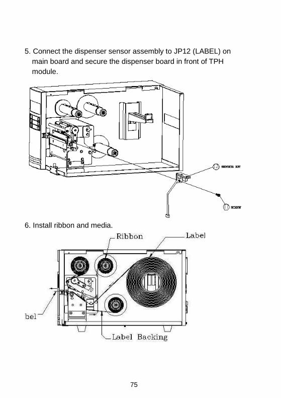
5. Connect the dispenser sensor assembly to JP12 (LABEL) on
main board and secure the dispenser board in front of TPH
module.
6. Install ribbon and media.