g2: testing characteristic of mccb used in and...
TRANSCRIPT

Utilization of Electric Power Laboratory‐3rd Year‐ 2013
G2: Testing & Characteristic of MCCB Used in Commercial and Industrial Applications
Utilization of Electric Power Laboratory‐3rd Year‐ 2013
2
Contents 1. Laboratory Objective ................................................................................................... 4
2. MECHANICAL OPERATION TESTS .................................................................................. 4
2.1 Purpose .............................................................................................................. 4
2.2 Procedure ............................................................................................................. 4
2.3 Results .................................................................................................................. 4
3. INSULATION RESISTANCE TEST ..................................................................................... 4
3.1 Purpose .............................................................................................................. 4
3.2 Equipment .......................................................................................................... 5
3.3 Procedure ........................................................................................................... 5
3.4 Test ..................................................................................................................... 5
3.5 Results ................................................................................................................ 5
4. INDIVIDUAL POLE RESISTANCE TEST (MILLIVOLT DROP) .................................................. 6
4.1 Purpose .............................................................................................................. 6
4.2 Equipment .......................................................................................................... 6
4.3 Procedure ........................................................................................................... 7
4.4 Test ..................................................................................................................... 7
4.5 Results ................................................................................................................ 7
5. INVERSE‐TIME OVER CURRENT TRIP TEST ...................................................................... 7
5.1 Purpose .............................................................................................................. 7
5.2 Equipment .......................................................................................................... 7
5.3 Procedure ........................................................................................................... 7
5.4 Test ......................................................................................................... 7
5.5 Results ................................................................................................................ 8
6. INSTANTANEOUS OVER CURRENT TRIP TEST ................................................................ 11
6.1 Purpose ............................................................................................................ 11
6.2 Equipment ........................................................................................................ 11
6.3 Procedure ......................................................................................................... 11
6.4 Test ................................................................................................................... 11
6.4.1 Run-Up Method .......................................................................................... 11
6.4.2 Pulse Method ............................................................................................. 12
6.5 Results .............................................................................................................. 13
7. RATED HOLD‐IN TEST ................................................................................................. 13
7.1 Purpose ............................................................................................................ 13

Utilization of Electric Power Laboratory‐3rd Year‐ 2013
3
7.2 Procedure ......................................................................................................... 13
7.3 Equipment ........................................................................................................ 13
7.4 Test ................................................................................................................... 13
7.5 Results .............................................................................................................. 13
8. Experiment data, recorded by student: ....................................................................... 14
9. Report ...................................................................................................................... 15
Utilization of Electric Power Laboratory‐3rd Year‐ 2013
4
1. Laboratory Objective • To be familiar with measurement and test equipments used for C.B. testing • To know different types of tripping units of C.B. • To understand tripping characteristic curve of C.B • To be familiar with main non-destructive testing applied on MCCB
The following non-destructive tests may be used to verify specific operational characteristics of molded case breakers:
A. Mechanical operation test B. Insulation resistance test C. Individual pole resistance test (millivolt drop test) D. Inverse time over current trip test E. Instantaneous over current trip test F. Rated hold-in test.
Note‐ All Tests above are according to ANSI/NEMA AB 4‐2009 (Guidelines for Inspection and Preventive Maintenance of Molded‐Case Circuit Breakers Used in Commercial and Industrial Applications)
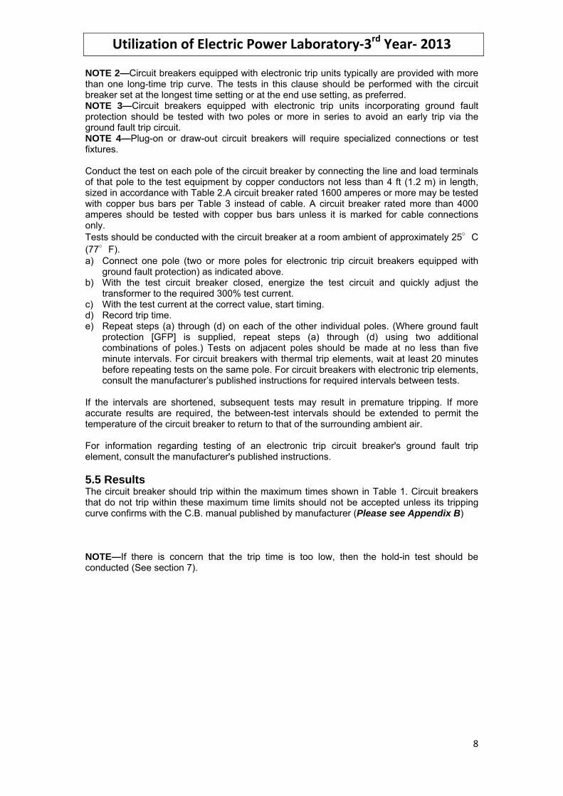
2. MECHANICAL OPERATION TESTS 2.1 Purpose To verify that the circuit breaker mechanism is operating freely. 2.2 Procedure
• After the circuit breaker is properly isolated, operate it ON and OFF 2 or 3 times. The breaker handle should operate smoothly without binding.
• Using an ohmmeter or other indicating device, verify that all circuit breaker contacts are open when the handle is in the OFF position and closed when the handle is in the ON position.
• For breakers that are provided with mechanical trip provisions (generally indicated by a test button) operate the tripping means according to the manufacturer's instructions. With the breaker in the tripped position, verify that the contacts are open using an ohmmeter (or other indicating device). Reset the breaker according to the manufacturer's instructions and operate the breaker to the ON and OFF positions. Use an ohmmeter (or other indicating device) to verify that all the contacts are closing and opening respectively.
2.3 Results The breaker should be replaced if:
A. The contacts are not open with the breaker in the tripped or OFF position B. The contacts are not closed with the breaker in the ON position C. The breaker does not reset D. The mechanical trip provisions (if provided) do not trip the breaker
3. INSULATION RESISTANCE TEST 3.1 Purpose To determine the adequacy of the insulation between line and load terminals, between poles, and between each pole and ground.

Utilization of Electric Power Laboratory‐3rd Year‐ 2013
5
3.2 Equipment This test requires an insulation resistance tester capable of applying a direct-current voltage of at least 500 volts. It should be also noted that more accurate information can be obtained when 1000 volt testers are used since they are more likely to detect deteriorated insulation systems (See Figure 1).
Figure 1: Insulation Resistance Test Set-Up
3.3 Procedure After being properly isolated, remove the breaker from the enclosure. In cases where the circuit breaker can be safely isolated/disconnected from line and load connections as installed, the test may be performed with the circuit breaker in its equipment. 3.4 Test
• All exposed metal parts except line, load, and accessory terminals should be electrically connected to a metal base-plate.
• Using an insulation resistance tester, apply a direct-current voltage of at least 500 volts to determine the resistance. Voltage is to be applied as follows:
a. Between line and load terminals of each individual pole with the circuit breaker in the OFF position and tripped position if possible.
b. Between terminals of adjacent poles with the circuit breaker in the ON position.
c. From line terminals to the metal base-plate with the circuit breaker in the ON position.
3.5 Results All resistance readings should be one megohm or greater for each measurement. Any reading less than one megohm may indicate the Circuit breaker is contaminated, flawed, or cracked insulating material, in this case; the circuit breaker should be replaced

Utilization of Electric Power Laboratory‐3rd Year‐ 2013
6
4. INDIVIDUAL POLE RESISTANCE TEST (MILLIVOLT DROP) See Figure 2 and Figure 3 for typical test set up.
Figure 2: Individual Pole Resistance Test Set‐Up
Figure 3: Individual Pole Resistance Test Set‐Up
4.1 Purpose To assess the electrical integrity of internal connections and contacts in a circuit breaker. This can be done by conducting a millivolt drop test across the line and load terminals of each pole with the circuit breaker contacts closed. The millivolt drop (resistance) of a circuit breaker pole can vary significantly due to inherent variability in the extremely low resistance of the electrical contacts and connectors. Such variations do not necessarily predict unacceptable performance and should not be used as the sole criteria for determination of acceptability (See 4.5). 4.2 Equipment
• This test should be conducted using a 24 volt, or less, direct current power supply capable of supplying the rated current of the circuit breaker. For circuit breakers rated

Utilization of Electric Power Laboratory‐3rd Year‐ 2013
7
higher than 500 amperes, the power supply should be capable of delivering no less than 500 amperes.
• If the above equipment is not available for field tests, a Digital Low Resistance Ohmmeter (DLRO), or 4-point tester, capable of 10 to 100 amperes (DC), may be used.
. 4.3 Procedure After being properly isolated, remove the breaker from the enclosure. In cases where the circuit breaker can be safely isolated/disconnected as installed, the test may be performed with the circuit breaker in its equipment. 4.4 Test 4.4.1 The test is performed as follows:
a) Apply test current across a pole equal to the breaker rating (or 500 Amperes minimum for breakers rated in excess of 500 Amperes). Record the millivolt drop and the test current. Do not maintain current for more than 1 minute. If this equipment is not available, use the following test.
b) Apply test current across a pole of 10 Amperes, or the Ampere rating of the breaker, for breakers rated less than 100 Amperes. For breakers rated more than 100 Amperes, apply a test current across a pole of 100 Amperes. Record the millivolt drop and the test current, or resistance. Do not maintain current for more than 1 minute.
c) De-energize the test circuit. Manually operate the breaker to the OFF and then ON positions.
d) Repeat steps (a) and (b) for a total of three readings on the pole being tested. e) Repeat steps (a) through (c) for each of the remaining poles of the circuit breaker.
4.5 Results The results of test will vary according to the breaker frame type, ampere rating, and manufacturer. The manufacturer should be consulted to determine the maximum allowable voltage drop (Please see Appendix A). If the average test values of any pole of the breaker exceed the maximum allowable drop, the circuit breaker may have reached the end of life and additional tests may have to be conducted. 5. INVERSE-TIME OVER CURRENT TRIP TEST 5.1 Purpose To verify the operation of the inverse-time over current tripping function of a circuit breaker. This test is not applicable to instantaneous only breakers or molded case switches. 5.2 Equipment Variable low voltage power supply, including an RMS reading ammeter capable of delivering the required test current for the maximum test duration as shown in Table 1. Circuit breakers with electronic trip units are often equipped with integral test provisions for verifying the functional operation of the trip unit. Where integral test provisions are not included, separate test devices are frequently available from the circuit breaker manufacturer. When using either of these alternate test means, the instructions of the manufacturer must be followed. 5.3 Procedure After being properly isolated, remove the breaker from the enclosure. In cases where the circuit breaker can be safely isolated/disconnected from line and load connections as installed, the test may be performed with the circuit breaker in its equipment. 5.4 Test NOTE 1—These tests should be conducted on individual circuit breaker poles using a test current of 300% of the circuit breaker's rated current. This test current has been chosen because it is relatively easy to attain and the wattage per pole is low enough that the transfer of heat into the adjacent poles is minor and does not appreciably affect the test results.
Utilization of Electric Power Laboratory‐3rd Year‐ 2013
8
NOTE 2—Circuit breakers equipped with electronic trip units typically are provided with more than one long-time trip curve. The tests in this clause should be performed with the circuit breaker set at the longest time setting or at the end use setting, as preferred. NOTE 3—Circuit breakers equipped with electronic trip units incorporating ground fault protection should be tested with two poles or more in series to avoid an early trip via the ground fault trip circuit. NOTE 4—Plug-on or draw-out circuit breakers will require specialized connections or test fixtures. Conduct the test on each pole of the circuit breaker by connecting the line and load terminals of that pole to the test equipment by copper conductors not less than 4 ft (1.2 m) in length, sized in accordance with Table 2.A circuit breaker rated 1600 amperes or more may be tested with copper bus bars per Table 3 instead of cable. A circuit breaker rated more than 4000 amperes should be tested with copper bus bars unless it is marked for cable connections only. Tests should be conducted with the circuit breaker at a room ambient of approximately 25°C (77°F). a) Connect one pole (two or more poles for electronic trip circuit breakers equipped with
ground fault protection) as indicated above. b) With the test circuit breaker closed, energize the test circuit and quickly adjust the
transformer to the required 300% test current. c) With the test current at the correct value, start timing. d) Record trip time. e) Repeat steps (a) through (d) on each of the other individual poles. (Where ground fault
protection [GFP] is supplied, repeat steps (a) through (d) using two additional combinations of poles.) Tests on adjacent poles should be made at no less than five minute intervals. For circuit breakers with thermal trip elements, wait at least 20 minutes before repeating tests on the same pole. For circuit breakers with electronic trip elements, consult the manufacturer’s published instructions for required intervals between tests.
If the intervals are shortened, subsequent tests may result in premature tripping. If more accurate results are required, the between-test intervals should be extended to permit the temperature of the circuit breaker to return to that of the surrounding ambient air. For information regarding testing of an electronic trip circuit breaker's ground fault trip element, consult the manufacturer's published instructions. 5.5 Results The circuit breaker should trip within the maximum times shown in Table 1. Circuit breakers that do not trip within these maximum time limits should not be accepted unless its tripping curve confirms with the C.B. manual published by manufacturer (Please see Appendix B) NOTE—If there is concern that the trip time is too low, then the hold-in test should be conducted (See section 7).

Utilization of Electric Power Laboratory‐3rd Year‐ 2013
9
Table 1 VALUES FOR INVERSE TIME TRIP TEST
(At 300% of Rated Continuous Current of Circuit Breaker)

Utilization of Electric Power Laboratory‐3rd Year‐ 2013
10
Table 2 COPPER TEST CONDUCTOR SELECTION

Utilization of Electric Power Laboratory‐3rd Year‐ 2013
11
Table 3 SIZE OF COPPER BUSBAR CONNECTIONS
6. INSTANTANEOUS OVER CURRENT TRIP TEST 6.1 Purpose To verify the operation of the instantaneous trip functions under field test conditions. Accordingly, the tolerances given in Table 4 are necessarily broader than the manufacturer's factory tolerances. 6.2 Equipment The same equipment as utilized in section 5 is required with the following exceptions:
a. For the run-up method of testing a pointer-stop ammeter or other types of meters (digital) capable of reading and recording, the maximum current reached prior to tripping may be used.
b. For the pulse method of testing, a calibrated image-retaining oscilloscope, or a high speed sampling rate digital ammeter (capable of accurately measuring a half-cycle pulse) is required instead of an ammeter
6.3 Procedure After being properly isolated, remove the breaker from the enclosure. In cases where the circuit breaker can be safely isolated/disconnected from line and load connections as installed, the test may be performed with the circuit breaker in its equipment. 6.4 Test Since the instantaneous trip characteristics of the circuit breaker can be influenced by stray magnetic fields, the test setup must be made in such a way that the fields caused by the test equipment itself, by steel enclosures, mounting plates, or by the conductors to the circuit breaker, do not affect the test results. Results can also be influenced by the wave shape of the current and, therefore, it is desirable to have sinusoidal output from the supply equipment. Manufacturers may be consulted for individual recommendations on mounting and wire routing if desired. The two methods which may be used for testing the instantaneous trip function are the "run-up" and the "pulse" methods. 6.4.1 Run-Up Method
a. Connect one pole of the test breaker to the test equipment as indicated in section 5, adjust the trip setting to the desired position, and operate the breaker to the ON position.
b. Set the current control to a point where approximately 60% of the current setting will flow when the circuit is energized.
c. Turn the power ON and increase the current until the circuit breaker trips. The recommended time for increasing the current is between two and five seconds. If the circuit breaker does not open within five seconds, the supply circuit should be turned
Utilization of Electric Power Laboratory‐3rd Year‐ 2013
12
OFF to prevent damage to the test equipment and overheating of the circuit breaker thermal elements.
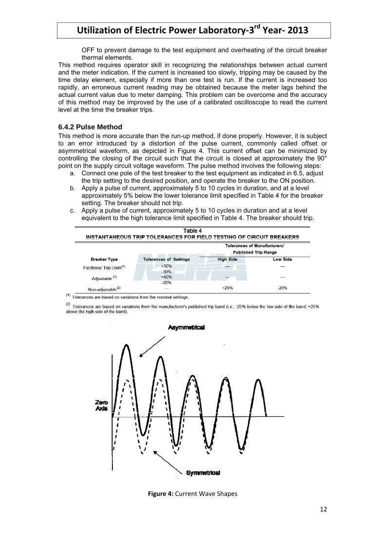
This method requires operator skill in recognizing the relationships between actual current and the meter indication. If the current is increased too slowly, tripping may be caused by the time delay element, especially if more than one test is run. If the current is increased too rapidly, an erroneous current reading may be obtained because the meter lags behind the actual current value due to meter damping. This problem can be overcome and the accuracy of this method may be improved by the use of a calibrated oscilloscope to read the current level at the time the breaker trips. 6.4.2 Pulse Method This method is more accurate than the run-up method, if done properly. However, it is subject to an error introduced by a distortion of the pulse current, commonly called offset or asymmetrical waveform, as depicted in Figure 4. This current offset can be minimized by controlling the closing of the circuit such that the circuit is closed at approximately the 90° point on the supply circuit voltage waveform. The pulse method involves the following steps:
a. Connect one pole of the test breaker to the test equipment as indicated in 6.5, adjust the trip setting to the desired position, and operate the breaker to the ON position.
b. Apply a pulse of current, approximately 5 to 10 cycles in duration, and at a level approximately 5% below the lower tolerance limit specified in Table 4 for the breaker setting. The breaker should not trip.
c. Apply a pulse of current, approximately 5 to 10 cycles in duration and at a level equivalent to the high tolerance limit specified in Table 4. The breaker should trip.
Figure 4: Current Wave Shapes

Utilization of Electric Power Laboratory‐3rd Year‐ 2013
13
6.5 Results Test results should be in accordance with the values shown in Table 4. If the results differ significantly from those values, reexamine the test circuit and circuit breaker mounting arrangements (See 6.4). If there are no apparent problems with the test circuit or mounting arrangements, the circuit breaker should be replaced. 7. RATED HOLD-IN TEST 7.1 Purpose To verify the capability of a molded case circuit breaker to carry its rated current. 7.2 Procedure Remove the breaker from the enclosure. In cases where the circuit breaker can be safely isolated or disconnected as installed, the test may be performed with the circuit breaker in its equipment. 7.3 Equipment A low voltage power supply such as that described in section 5.2 is required to conduct this test. 7.4 Test The circuit breaker should be tested with the operating mechanism set to the ON position, in open air, with all poles connected in series by copper conductors not less than 4 ft (1.2 m) in length, selected in accordance with Table 2. The test should be performed at room ambient temperature approximately 25°C (77°F). The power supply should be adjusted to deliver rated current until the circuit breaker temperature stabilizes. Temperature stabilization usually occurs within one hour for breakers rated 100 amperes or less, but will take several hours for breakers of higher rating. Stabilization may be verified by taking three successive temperature measurements at intervals of 10 to 20 minutes between measurements at the same location on one or more of the circuit breaker connectors utilizing a temperature probe or thermocouple instrument. 7.5 Results The circuit breaker should not trip during the test. If it does trip, reset the breaker and turn it ON again while continuing to monitor connector temperatures for an indication of temperature stabilization. If the breaker continues to trip or if any of its terminals reach temperatures higher than 80ºC above ambient, it should not be accepted.

Utilization of Electric Power Laboratory‐3rd Year‐ 2013
14
8. Experiment data, recorded by student: Student Name: Sec.: B.N.:
1.Mechanical operation test
A. The contacts are not open with the breaker in the tripped or OFF position B. The contacts are not closed with the breaker in the ON position C. The breaker does not reset D. The mechanical trip provisions (if provided) do not trip the breaker E. C. B is working
2. Insulation resistance test The C.B in OFF Position Value The resistance Between pole 1 "Line" and 1 "Load" ≥ The resistance Between pole 2 "Line" and 2 "Load" ≥ The resistance Between pole 3 "Line" and 3 "Load" ≥ The C.B in TRIP Position The resistance Between pole 1 "Line" and 1 "Load" ≥ The resistance Between pole 2 "Line" and 2 "Load" ≥ The resistance Between pole 3 "Line" and 3 "Load" ≥ The C.B in ON Position The resistance Between pole 1 and 2 ≥ The resistance Between pole 2 and 3 ≥ The resistance Between pole 1 and 3 ≥ 3.Individual pole resistance test (millivolt drop test) The C.B in ON Position The resistance Between pole 1 "Line" and 1 "Load" The resistance Between pole 2 "Line" and 2 "Load" The resistance Between pole 3 "Line" and 3 "Load" 4. Tripping Curve Test Write C.B Protecting Setting Ir= , Tr= ,Isd= ,Tsd= ,Iinst= % From Ir Injected
Current Value
Tripping Time Value
Fault Type
Comments

Utilization of Electric Power Laboratory‐3rd Year‐ 2013
15
9. Report a) Compare between the true RMS multi‐meter and general digital multi‐meter. b) What is the Circuit that may be used in the electronic MEGGER which can
generate 5000 VDC from 6 VDC? Mention Circuit name, draw a figure for the circuit, and illustrate its operation
c) Fill up a table of all devices used in the experiment and mention the function of each device
d) Fill up a table for all readings recorded in the experiment e) What is the Hall Effect phenomena "brief description"?

Utilization of Electric Power Laboratory‐3rd Year‐ 2013
16
APPENDIX A

Installation recommendations
Power loss/ ResistanceCompact NSX equipped with thermal-magnetic trip units
Compact NSX thermal power loss values
are used to calculate total temperature rise
in the switchboard in which the circuit
breakers are installed.
The values indicated in the tables below are typical values for a device at full rated load and 50/60 Hz.
Power loss per pole (P/pole) in Watts (W)The value indicated is the power loss at IN, 50/60 Hz, for a three-pole or four-pole circuit breaker. Measurement and calculation of power loss are carried out in compliance with the recommendations of Annex G of standard IEC 60947-2.
Resistance per pole (R/pole) in milliohms (mΩ)The value of the resistance per pole is provided as a general indication for a new device.The value of the contact resistance must be determined on the basis of the measured voltage drop, in accordance with the manufacturer's test procedure (ABT
instruction document no. 1 - BEE - 02.2 -A).Note: this measurement is not sufficient to determine the quality of the contacts, i.e. the capacity of the circuit breaker to carry its rated current.
Additional power lossAdditional power loss is equal to the sum of the power dissipated by the following:
Vigi module: note that the deviation of the N and L3 bars required to pass through the toroid results in higher power losses compared to those of the L1 and L2 bars (diagram opposite). When calculating total power loss, use L1, L2, L3 for a 3P device and N, L1, L2, L3 for a 4P device
disconnecting contacts (plug-in and withdrawable devices)ammeter moduletransformer module.
Calculation of total power lossTotal power loss at full rated load and 50/60 Hz is equal to the sum of the device and additional power losses per pole multiplied by the number of poles (2, 3 or 4).If a Vigi module is installed, it is necessary to differentiate between N and L3 on one hand and L1 and L2 on the other.
Compact NSX100 to 250 equipped with TM-D and TM-G trip units
Type of device Fixed device Additional power / pole
3/4 poles Rat. (A)
R/pole P/pole Vigi (N, L3)
Vigi (L1, L2)
Plug-in / withdr.
Ammetermodule
Transfo. module
NSX100 16 11.42 2.92 0 0 0 0 025 6.42 4.01 0 0 0.1 0 032 3.94 4.03 0.06 0.03 0.15 0.1 0.140 3.42 5.47 0.10 0.05 0.2 0.1 0.150 1.64 4.11 0.15 0.08 0.3 0.1 0.163 2.17 8.61 0.3 0.15 0.4 0.1 0.180 1.37 8.77 0.4 0.2 0.6 0.1 0.1100 0.88 8.8 0.7 0.35 1 0.2 0.2
NSX160 80 1.26 8.06 0.4 0.2 0.6 0.1 0.1100 0.77 7.7 0.7 0.35 1 0.2 0.2125 0.69 10.78 1.1 0.55 1.6 0.3 0.3160 0.55 13.95 1.8 0.9 2.6 0.5 0.5
NSX250 125 0.61 9.45 1.1 0.55 1.6 0.3 0.3160 0.46 11.78 1.8 0.9 2.6 0.5 0.5200 0.39 15.4 2.8 1.4 4 0.8 0.8250 0.3 18.75 4.4 2.2 6.3 1.3 1.3
Compact NSX100 to 630 equipped with MA/1.3-M trip units
Type of device Fixed device Additional power / pole3 poles Rat.
(A)R/pole P/pole Vigi
(N, L3)Vigi (L1, L2)
Plug-in / withdr.
Ammetermodule
Transfo. module
NSX100 2.5 148.42 0.93 0 0 0 0 06.3 99.02 3.93 0 0 0 0 012.5 4.05 0.63 0 0 0 0 025 1.66 1.04 0 0 0.1 0 050 0.67 1.66 0.2 0.1 0.3 0.1 0.1100 0.52 5.2 0.7 0.35 1 0.2 0.2
NSX160 150 0.38 8.55 1.35 0.68 2.6 0.45 0.45NSX250 220 0.3 14.52 2.9 1.45 4.89 0.97 0.97NSX400 320 0.12 12.29 3.2 1.6 6.14 1.54 1.54NSX630 500 0.1 25 13.99 7 15 3.75 3.75
b
bbb
DB11
5052 N L1 L2 L3
With a Vigi module, the deviation of the N and L3 bars required to pass through the toroid results in higher power losses compared to those of the L1 and L2 bars.
B-10

Compact NSX equipped with electronic trip units
The values indicated in the table below are typical values for a device at full rated load and 50/60 Hz. The definitions and information are the same as that for circuit
breakers equipped with thermal-magnetic trip units.
Compact NSX100 to 630 equipped with Micrologic trip units
Type of device Fixed device Additional power / pole3/4 poles Rat.
(A)R/pole P/pole Vigi
(N, L3)Vigi (L1, L2)
Plug-in / withdr.
Ammetermodule
Transfo. module
NSX100 40 0.84 1.34 0.1 0.05 0.2 0.1 0.1100 0.468 4.68 0.7 0.35 1 0.2 0.2
NSX160 40 0.73 1.17 0.4 0.2 0.6 0.1 0.1100 0.36 3.58 0.7 0.35 1 0.2 0.2160 0.36 9.16 1.8 0.9 2.6 0.5 0.5
NSX250 100 0.27 2.73 1.1 0.55 1.6 0.2 0.2250 0.28 17.56 4.4 2.2 6.3 1.3 1.3
NSX400 400 0.12 19.2 3.2 1.6 9.6 2.4 2.4NSX630 630 (1) 0.1 39.69 6.5 3.25 19.49 5.95 5.95
(1) The power loss values for the Vigi modules and withdrawable circuit breakers are given for 570 A.
B-11

APPENDIX B
