g3 digital high volume combo brewers · g3 digital high volume combo brewers user guide read and...
TRANSCRIPT
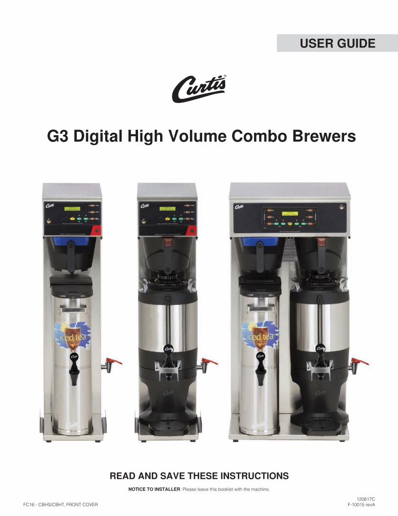
G3 Digital High Volume Combo Brewers
USER GUIDE
READ AND SAVE THESE INSTRUCTIONS NOTICE TO INSTALLER: Please leave this booklet with the machine.
CONTENTS CL16
..............................................................................................FS16
............................................................................................................................................... IS2
.............................................................................................................................. II2
................................................................................... II10
............................................................................................................................................OI13
.................................................................................................................................CI1
.................................................................................................CI5
...................................................................................................................CI6
...............................................................................................................................................
..................................................................................................................
..................................................................................................................
............................................................................................ IP16
............................................................................ IP25
.............................................................................. IP26
................................................................................................................ES21
................................................................................................................ES22
............................................................................................................................
....................................................................................................................
.............................................................................................................................................................
....................................................................................................................................................
120817B
Contact Information
Wilbur Curtis Co., Inc.6913 Acco Street | Montebello, CA 90640 US
Phone: 323-837-2300 | Toll Free: 800-421-6150Email: [email protected] | Web: www.wilburcurtis.com
A.M. - 4:00 P.M. PTEmail: [email protected]

KEY FEATURES/SPECIFICATIONS/SYSTEM REQUIREMENTS FS16
Key Features
•
•
•
•
•
Single, High Volume, Combo Brewer 1 PH 110/220 V 15.0/12.7 A 2 X 1600 W 2W/3W + G1800 W/ 2800 W
50/60 Hz 12.0
Twin, High Volume, Combo Brewer 1 PH 220 V 23.0/34.0 A 3 X 2500 W 3W + G5100 W/ 7500 W
50/60 Hz 21.0
36.71” 10.07” 22.82” 47.0 lbs 9.27 cu ft 20 - 90 psi 1.0 gpm
36.75” 18.13” 22.88” 119.4 lbs 16.00 cu ft 20 - 90 psi 2.0 gpm
•
•
•
•
•
IMPORTANT SAFEGUARDS IS2
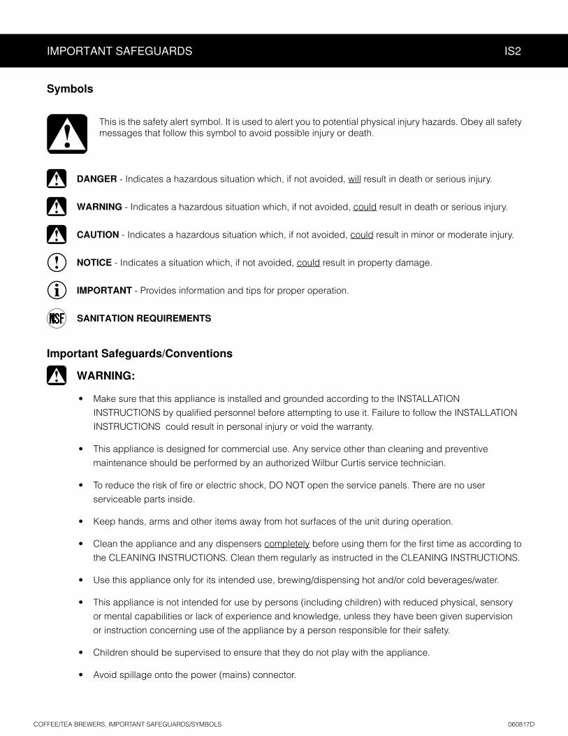
Symbols
This is the safety alert symbol. It is used to alert you to potential physical injury hazards. Obey all safety messages that follow this symbol to avoid possible injury or death.
DANGER - Indicates a hazardous situation which, if not avoided, will result in death or serious injury.
WARNING - Indicates a hazardous situation which, if not avoided, could result in death or serious injury.
CAUTION - Indicates a hazardous situation which, if not avoided, could result in minor or moderate injury.
NOTICE - Indicates a situation which, if not avoided, could result in property damage.
IMPORTANT - Provides information and tips for proper operation.
SANITATION REQUIREMENTS
Important Safeguards/Conventions
WARNING:
• Make sure that this appliance is installed and grounded according to the INSTALLATION
INSTRUCTIONS could result in personal injury or void the warranty.
• This appliance is designed for commercial use. Any service other than cleaning and preventive
maintenance should be performed by an authorized Wilbur Curtis service technician.
•
serviceable parts inside.
• Keep hands, arms and other items away from hot surfaces of the unit during operation.
• Clean the appliance and any dispensers completely
the CLEANING INSTRUCTIONS. Clean them regularly as instructed in the CLEANING INSTRUCTIONS.
• Use this appliance only for its intended use, brewing/dispensing hot and/or cold beverages/water.
• This appliance is not intended for use by persons (including children) with reduced physical, sensory
or mental capabilities or lack of experience and knowledge, unless they have been given supervision
or instruction concerning use of the appliance by a person responsible for their safety.
• Children should be supervised to ensure that they do not play with the appliance.
• Avoid spillage onto the power (mains) connector.
IMPORTANT SAFEGUARDS IS2
CE Requirements
• This appliance must be installed in locations where it can be overseen by trained personnel.
•
•
•
• This appliance must not be cleaned by water jet.
• instruction concerning use of the appliance in a safe way and if they understand the hazards involved.
•
• or lack of experience and knowledge if they have been given supervision or instruction concerning use of the appliance in a safe way and understand the hazards involved.
•
• If the power cord is ever damaged, it must be replaced by the manufacturer or authorized service personnel with a special cord available from the manufacturer or its authorized service personnel in order to avoid a hazard.
• Machine must not be immersed for cleaning.
• supervised.
• This appliance is intended to be used in household and similar applications such as:
– bed and breakfast type environments.
• This appliance not intended to be used in applications such as:
– farm houses
• Access to the service areas permitted by Authorized Service personnel only.
•

INSTALLATION INSTRUCTIONS II2
Installation Instructions
Installation Requirements
• A secure surface capable of supporting the weight of the appliance.
• For units without an attached cord set: Appropriately sized, UL listed, grounding type power cable to meet
enough
• appliance (see SPECIFICATIONS
• www.wilburcurtis.com
•
unit. See the SPECIFICATIONS section for the correct size. The water line should also be capable of being
1 appliance
2 federal, state and local codes.
installed and maintained in accordance with federal, state and local codes.
WARNING:
WARNING:properly grounded.
NOTICE:SPECIFICATIONS section.
IMPORTANT:
in compliance with federal, state and local codes. For units installed outside of the U.S.A., make sure that the installation is in compliance with the applicable plumbing/sanitation code for your area.

Installation
Leveling
1 Position the brewer on the countertop. Level it left to right and front to back by turning the bottom of the legs.
Connect the Water Supply
2 Flush the water supply line prior to installation to
3 the back of the brewer. Leave the water supply valve closed until the hot water faucet is installed and power is connected.
Install the Hot Water Faucet
4 Remove the screws that hold the front cover in place and remove the cover.
5 Carefully remove the round plug from the faucet hole on the left or right side panel depending on the desire faucet mounting location.
INSTALLATION INSTRUCTIONS II10
HIGH VOLUME COMBO BREWERS, INSTALLATION INSTRUCTIONS 120817B
WARNING: Use the leveling legs to level the brewer only. Do not use them to adjust brewer height. Do not extend them higher than necessary.
High volume combo brewers have a water tank
faucet. The faucet ships loose with the brewer so that the customer can decide if they want it installed. If you are NOT installing the hot water faucet AND the brewer being installed will be connected to 120 Volts, skip to step 20.
Plug
Frontpanel
Sidepanel
6 Locate the faucet and insert the shaft into the faucet hole.
7 From inside the brewer slide the lock washer over the faucet shank. Then, thread the nut onto the faucet shank.
8 Hold the body of the faucet while tightening the nut with a 3/4” socket.

9 Locate the hot water tube that runs from the hot water tank inside the brewer. It has a plug in the end of it.
10 Remove the plug from the hot water tube.
11 Slide the end of the hot water tube over the smooth section of the faucet shank inside the brewer, as far as it will go.
12 For dual voltage brewers that will be operated at 120 Volts, replace the front cover and skip to step 20.
Connect the Brewer Wiring
Brewers without a cord set attached and dual voltage brewers that will be set up for 220 Volt operation.
13 Loosen the strain relief on the back of the brewer.
14 For dual voltage units that will be operating at 220 Volts, disconnect the 120 Volt power cord wires from the power block inside the brewer and remove the the power cord. Disconnect and cap one end of the jumper wire between the “C” and “N” terminals on the power block.
15 Twin units are equipped with three elements. To operate with two elements (5100 Watts), disconnect and cap one end of the jumper wire between the “C” and “N” terminals on the power block. To operate with three elements (7500 Watts) the jumper wire must be connected.
16 Feed the 220 Volt power cable through the strain relief, into the brewer.
17 Strip and connect the power cable wires to the power block inside the unit.
18 Tighten the strain relief.
19 Replace the front cover.
20 Connect the power cable wires to the terminals in the junction box. See the ELECTRICAL SCHEMATIC for the power supply requirements.
INSTALLATION INSTRUCTIONS II10
HIGH VOLUME COMBO BREWERS, INSTALLATION INSTRUCTIONS 120817B
Installation (cont.)
WARNING: Turn off power to the junction box at the circuit breaker panel before connecting the power cable to the brewer. Lock out and tag the circuit breaker.
Powerblock

Brewers With A Cord Set Attached
21 Connect the power cord to the appropriate electrical outlet.
Power Up the Brewer
22 Turn on the water supply valve.
23 Make sure that the circuit breaker supplying power to the unit is on.
24 Turn the toggle switch on the back of the brewer to the
25 When the water level in the tank rises to the correct volume, the heating elements will turn on automatically. Depending on the incoming water
water tank typically requires 20 to 30 minutes to reach the factory set operating temperature. When the water has heated, Ready to brew will be displayed
dispense 12 ounces of hot water through the hot water faucet to help purge air from the tubing inside the brewer.
26 Perform a brew cycle of a least 12 ounces to purge any remaining air from the system. See OPERATING INSTRUCTIONS. During the initial brew cycle and
water tank.
INSTALLATION INSTRUCTIONS II10
IMPORTANT: When operating the brewer at higher elevations, reduce the factory set operating temperature (204°F) by 2°F for each 1000 feet of elevation above 2000 feet. See the PROGRAMMING GUIDE.
WARNING: Connect the power cord to the appropriate type and size electrical outlet. If the electrical outlet is not compatible with the power cord, have it upgraded by a licensed electrician. Do not modify the power plug. Do not use an extension cord. Do not use a power cord/plug that is damaged.
HIGH VOLUME COMBO BREWERS, INSTALLATION INSTRUCTIONS 120817B

OPERATING INSTRUCTIONS OI13
Brewing Instructions
2 Remove/open an empty coffee or tea dispenser and position it on the brew deck. Center it under the brew basket.
TEADISPENSER
3 Select the brew basket labeled for the type of beverage being brewed (coffee, iced tea or iced coffee*) and insert a clean
4 Fill with the proper amount of coffee or leaf tea. Level the
5 into the brew rails under the control panel. Slide it all the way back until it stops.
The brewer will brew coffee or tea based on the settings programmed into the universal control module (UCM). To change the settings, see the PROGRAMMING GUIDE.
* For models equipped for brewing iced coffee.
1 The brewer should be ON.
switch. “Ready to brew” should be on the display.
6 Press the brew button. Brewing will begin immediately.
WARNING - TO AVOID SCALDING, AVOID SPLASHING. Keep body parts clear of the brewer during brewing. Do not remove the brew basket while “Brewing” appears on the display.
WARNING - DO NOT refrigerate unused tea overnight for later consumption.
The G3 Combo Brewer is factory preset for optimal performance.
HIGH VOLUME COMBO BREWERS, OPERATING INSTRUCTIONS 082216NC
NOTICE - Do not use cleaning liquids, compounds or powders containing chlorine (bleach) or corrosives. USE OF THESE PRODUCTS WILL VOID
THE WARRANTY.
CLEANING INSTRUCTIONS CI1
Cleaning The Brewer - Daily
BREWERS - GENERIC, CLEANING INSTRUCTIONS 080416B
WARNING: HOT SURFACES - To avoid injury, allow the brewer and dispenser(s) to cool before cleaning.
The brewer should be OFF.
1 Remove the dispenser(s). Wipe exterior brewer surfaces with a damp cloth to remove spills and debris.
2 Remove the brew basket(s) and clean them in a mild detergent solution. Use a soft bristled brush for hard to clean areas. Rinse with clean water, then dry.
3 Wipe the spray head area with a cloth soaked in a mild detergent solution. Rinse with a cloth soaked with clean water removing any residual detergent. Use a clean, soft cloth to dry.
4 Dump out the drip tray(s) (if applicable). Rinse with clean water, then dry with a soft, clean cloth.
Cleaning The Brewer - Weekly
The brewer should be OFF.
1 Remove the spray head(s), unscrewing counterclockwise from the dome plate.
2 Thoroughly clean and rinse the dome plate area.
3 Clean the brew basket rails with a brush soaked with a mild detergent solution. Rinse the area with a cloth soaked with clean water, removing any residual detergent.
4 Dry the area with a soft, clean cloth.
5 Reattach the spray head(s).
WARNING: DO NOT immerse the brewer in water or any other liquid.

Cleaning the 1.0 Gallon or 1.5 Gallon Thermal Dispensers (Daily)
CLEANING INSTRUCTIONS CI5
WARNING: DO NOT immerse the thermal server or its lid assembly in water or any other liquid. Do not place the thermal server or lid in a dishwasher. Placing a thermal server in a dishwasher will void the warranty. To avoid damage, DO NOT use a brush to clean the faucet or the inside of the faucet shank (outlet).
Cleaning the Container
1 Prepare a mild solution of detergent and warm water. Remove the server from the brewer and remove the lid. Rinse.
Wash - Wipe the exterior surfaces of the container with a sponge soaked with the detergent solution
the liner with the detergent solution. Take a sponge brush and scrub out the stainless steel liner and the lid.
3 Rinse - Rinse with clean, warm water.
4 Sanitize - Sanitize the interior of the server and the lid, using a commercial sanitizer suitable for food grade applications. Sanitize according to the directions on the package.
5 Disassemble the faucet - Unscrew the handle/bonnet assembly from the top of the faucet and remove it. Inspect the seat cup for wear. Replace the seat cup if it is damaged. Disassemble the sight gauge (some versions). If the sight gauge has a cover, pull it up and off to remove. Remove the cap to disassemble the gauge (both versions). Some versions are equipped with a guard that must be unscrewed to access the lower
for cracks or chips. If broken, replace the glass with a new one.
Air Dry - Turn the container and lid upside down and allow to air dry.
Cleaning the Faucet Parts and Site Gauge
Wash - Wash all faucet and gauge glass parts with the detergent solution. Using the supplied brush,
of the gauge glass with a gauge brush soaked with detergent solution.
Rinse - Thoroughly rinse all parts with clean, warm water. continued....
FaucetAssembly
TXSG Series
TLCG Series
Seat cup
Handle
Bonnet
Cap
Lid
Washer
Washer
Guard
Glass tube
Float
FaucetAssembly
Seat cup
Handle
Cover
Lid
Bonnet
Cap
Glass tube
CLEANING INSTRUCTIONS CI5
Cleaning the Faucet Parts and Gauge Glass (cont.)
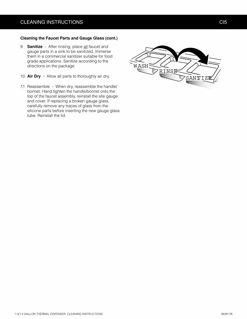
9 Sanitize - After rinsing, place all faucet and gauge parts in a sink to be sanitized. Immerse them in a commercial sanitizer suitable for food grade applications. Sanitize according to the directions on the package.
10 Air Dry - Allow all parts to thoroughly air dry.
11 Reassemble - When dry, reassemble the handle/bonnet. Hand tighten the handle/bonnet onto the top of the faucet assembly, reinstall the site gauge and cover. If replacing a broken gauge glass, carefully remove any traces of glass from the silicone parts before inserting the new gauge glass tube. Reinstall the lid.
WASH
SANITIZERINSE
CLEANING INSTRUCTIONS CI6
Cleaning the Tea Dispenser (Daily)
Cleaning the Container
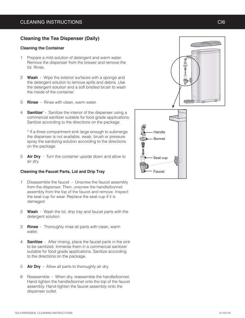
Prepare a mild solution of detergent and warm water. Remove the dispenser from the brewer and remove the lid. Rinse.
2 Wash - Wipe the exterior surfaces with a sponge and the detergent solution to remove spills and debris. Use the detergent solution and a soft bristled brush to wash the inside of the container.
3 Rinse - Rinse with clean, warm water.
4 Sanitize* - Sanitize the interior of the dispenser using a commercial sanitizer suitable for food grade applications. Sanitize according to the directions on the package. * If a three compartment sink large enough to submerge the dispenser is not available, swab, brush or pressure spray the sanitizing solution according to the directions on the package.
5 Air Dry - Turn the container upside down and allow to air dry.
Cleaning the Faucet Parts, Lid and Drip Tray
Disassemble the faucet - Unscrew the faucet assembly from the dispenser. Then, unscrew the handle/bonnet assembly from the top of the faucet and remove. Inspect the seat cup for wear. Replace the seat cup if it is damaged.
2 Wash - Wash the lid, drip tray and faucet parts with the detergent solution.
3 Rinse - Thoroughly rinse all parts with clean, warm water.
4 Sanitize - After rinsing, place the faucet parts in the sink to be sanitized. Immerse them in a commercial sanitizer suitable for food grade applications. Sanitize according to the directions on the package.
5 Air Dry - Allow all parts to thoroughly air dry.
6 Reassemble - When dry, reassemble the handle/bonnet. Hand tighten the handle/bonnet onto the top of the faucet assembly. Hand-tighten the faucet assembly onto the dispenser outlet.
Seat cup
Faucet
Handle
Bonnet

PROGRAMMING GUIDE PG5
1 CBHV-TWIN ‘SW’ and CBHV-SINGLE ‘SW’ models only.
To enter programming mode:
Return to Coffee Recipes (top)
Return to Brew Button Prog (top)
Return to Brew Button Prog (top)
Return to Tea Recipes (top)
Exit Programming Mode
Save and Exit Programming Mode
Select Brew Button!
Push a COFFEE BREW Button
Push a TEA BREW Button
Return to Non-Brew Program (top)
CBHV-Twin
CBHV-Single
CBHV-Twin-SW
CBHV-Single-SW
One Batch
Two Batch
Three Batch
Curtis
EnteringProgramming mode
Enter Code- - - -
<Program Menus>Select
With unit OFF, press and hold bottom right BREW button (4). Then press and release ON/OFF button (2). Continue to hold down BREW button until Enter Code appears.
Enter 4 digit code. (factory default = 1-2-3-4)
IMPORTANT: All programming functions are performed with the three center buttons.
The symbols below the buttons are:
Scroll LEFT/UP (1)
SELECT or ENTER to save new parameter (2)
Scroll RIGHT/DOWN (3)
Once you enter programming mode, press or to scroll LEFT/UP or RIGHT/DOWN through the various functions/features. Press (Select) to make chang-es to the function/feature displayed. Then press or to scroll through the various available settings. See Programming Menus for detailed descriptions.
WC-10007-102, PROGRAMMING GUIDE 090616NC

PROGRAMMING MENUS
After entering programming mode press or to display the various programming menus:
Press to enter the each individual programming menu. Detailed descriptions of each menu and the programmable features are below and on the following pages.
Coffee Recipes Menu
Sets coffee recipe. Press or to choose from Gourmet STD, Light Roast, Dark Roast, High Yield, Filter Pack or Decaf. Press to save and exit programming mode.
Non-Brew Program Menu
Temperature - adjusts the maximum tank water temperature. Once accessed ( ), press or to increase or decrease the temperature. The range is 170ºF to 208ºF. Press to save. Press to display the subsequent menu features.
Energy Save Mode - saves energy during periods when the brewer is not in use. When set to On, the brewer automatically shuts off four hours after the last brew cycle. Press the ON/OFF button to return to normal operation. When set to On-140ºF, the brewer shuts off four hours after the last brew cycle, but the water tank temperature remains at 140ºF. Use the On-140ºF setting to reach brewing temperature faster after periods of non-use. Once accessed ( ), press or to choose the desired setting. Press to save. Press to display the subsequent menu features.
Brew Count Odom - When accessed, this feature displays the total brew cycles since the odometer was last reset. Press to go back without resetting or to reset. Press to display the subsequent menu features.
Brew Count Total - when accessed ( ), displays the total brew cycles on the brewer. It cannot be reset. The display returns to the previous screen automatically after a few seconds. Press to display the subsequent menu features.
Cold Brew Lock - adjusts the temperature at which the brewer will brew when a BREW button is pressed (Ready to brew appears on the display). This feature also adjusts the temperature at which the heating element turns on to reheat the water in the tank. The available settings are 5°F, 15°F and Off. Off is within 30°F below the temperature setting. Once accessed ( ), press or to select the desired setting. Press to save. Press to display the subsequent menu features.
Master Reset - resets the brewer universal control module (UCM) to the factory default settings. Once accessed ( ), “Are You Sure?” will appear on the display. Press for Yes or for No. If you press No, the display goes back to the programming menu. If you press Yes, the UCM will reset and exit programming mode.
IMPORTANT: If you reset the UCM to the factory defaults, you MUST reprogram the Model Select to match the number on the model and the label on the UCM for proper operation. See Model Select.
continued...
PROGRAMMING GUIDE PG5
WC-10007-102, PROGRAMMING GUIDE 090616NC

PROGRAMMING GUIDE PG5
Non-Brew Program Menu (cont.)
Service Call - sets the service phone number that appears on the display when the UCM detects a SENSOR ERROR or WATER ERROR. Once accessed ( ), press or to select the number to be changed. Press repeatedly to change the number value. Press or to select the next number to change. When done, press
until ex . Press to display the subsequent menu features.
Access Code - sets the access code entered to access programming mode (the factory default is 1-2-3-4). Once accessed ( ), press or to select the number to be changed. Press repeatedly to change the number value. Press or to select the next number to change. When done, press until exdisplay and press . Press to display the subsequent menu features.
Banner Name - changes the banner name that appears on the display. No banner name appears when all blanks are entered. Once accessed ( ), press or to select the letter to change. Press repeatedly to change the letter. When done, press until ex . Press to display the subsequent menu features.
P-Maintenance - adjusts the P-Maintenance (preventive maintenance) brew monitor. When on, the UCM measures the number of gallons brewed before the P-Maintenance reminder appears on the display. The range is Off to 9500 gallons. Once accessed ( ), press or to select the desired setting, then press to save. Press to display the subsequent menu features.
Beeper On/Off - turns the beeper that is heard each time a button is pressed. Once accessed ( ), press or to toggle between On and Off. Press to save. Press to display the subsequent menu features.
Coffee Drip-Out - sets the Coffee Drip-Out time. Drip-out allows additional time for coffee to drain from the brew basket before “Brewing” disappears from the display. Once accessed ( ), press or to increase or decrease time. The range is Off to 5:00. Press to save. Press to display the subsequent menu features.
Tea Drip-Out - sets the Tea Drip-Out time. Drip-out allows additional time for tea to drain from the brew basket before “Brewing” disappears from the display. Once accessed ( ), press or to increase or decrease time. The range is Off to 9:00. Press to save. Press to display the subsequent menu features.
Displ. Brew Time - turns the display of the brew time during brewing On and Off. Once accessed ( ), press or to toggle between On and Off. Press to save. Press to display the subsequent menu features.
Display Messages - turns display of the message “Rinse Server Before Brewing” On or Off. Once accessed ( ), press or to toggle between On and Off. Press to save. Press to display the subsequent menu features.
Exit - Press exit Non-Brew Program menu and go back to programming mode main menu.
Brew Button Program Menu (COFFEE)
See Brew Button Program Menu (TEA) for programming a tea brew button. Press to access this menu, then press the coffee BREW button to be programmed. Press or to choose function to be programmed.
Brew By Volume - sets coffee brewing volume. Once accessed ( ), place an empty container under the (empty) brew basket, then press the BREW button for which the brew volume needs to be changed. Press the same BREW button again to start. When the desired volume is reached, press the BREW button again to stop
to display the subsequent menu features.
continued...
WC-10007-102, PROGRAMMING GUIDE 090616NC

Brew Button Program Menu (COFFEE, cont.)
Brew by Time - sets the amount of coffee brewed according to time. Once accessed ( ), press the BREW button for which the brew time needs to be changed. Press or to highlight minutes or seconds. Press
to change the setting. The range is 0:00 to 9:59. Once the amount of time is entered, press until ex is to save. Press to display the subsequent menu features.
Pre-Infusion - sets the Pre-Infusion time (Pulse Brew must be Off to access). Pre-infusion increases control of coffee clarity and extraction. Once accessed ( ), press the BREW button for which pre-infusion needs to be changed. Press or to change the setting. The range is Off to 60 seconds. Press to save. Press to display the subsequent menu features.
When Coffee Pre-infusion is On, Pulse Brew is disabled.
Pulse Brew On/Off - selects the Coffee Pulse Brew pattern (Pre-Infusion must be Off to access). The pulse ), press the BREW button
for which Pulse Brew needs to be changed. Press or to select the desired setting (see guidelines below for information on various settings). Press to save. Press to display the subsequent menu features.
When Coffee Pulse Brew is on, Pre-infuson is disabled.
Pulse Brew Guidelines
• Filter pack type coffees typically extract better with the A and B pulse setting. • Decaffeinated coffees typically extract better with the B pulse setting. • High-yield coffees typically extract better with the C pulse setting. Of course, any of the A, B or C
• Settings D and E are manual pulse counts.
By-Pass On/Off - turns by-pass feature On and Off. Press to access. Press or to toggle between On and Off. Press to save. Press to display the subsequent menu features.
Exit - Press exit Non-Brew Program menu and go back to programming mode main menu.
Brew Button Program Menu (TEA)
Press to access this menu, then press the tea BREW button to be programmed. Then press or to choose function to be programmed.
Tea by Volume - sets the tea brewing volume. Once accessed ( ), place an empty container under the (empty) brew basket, then press the BREW button for which the brew volume needs to be changed. When the
to display the subsequent menu features.
Tea by Time - sets the amount of tea brewed according to time. Once accessed ( ), press the BREW button for which the brew time needs to be changed. Press or to highlight minutes or seconds. Press to change the setting. The range is 0:00 to 9:59. Once the amount of time is entered, press then press to save. Press to display the subsequent menu features.
Tea Dilut. Delay - sets the delay until tea dilution begins. Once accessed ( ), press the BREW button for which the dilution delay needs to be changed. Press or to increase or decrease time. The range is 0:30 to 10:00. Press to save. Press to display the subsequent menu features.
continued...
PROGRAMMING GUIDE PG5
WC-10007-102, PROGRAMMING GUIDE 090616NC
PROGRAMMING GUIDE PG5
WC-10007-102, PROGRAMMING GUIDE 090616NC
Brew Button Program Menu (TEA, cont.)
Tea Dilut. Volume - sets the tea dilution volume. Once accessed ( ), place an empty container under the (empty) brew basket, then press the BREW button for which the dilution volume needs to be changed. When
been set. Press to display the subsequent menu features.
Tea Dilut. Time - sets the amount of tea dilution according to time. Once accessed ( ), press the BREW button for which the dilution time needs to be changed. Press or to highlight minutes or seconds. Press
to change the setting. The range is 0:00 to 9:59. Once the amount of time is entered, press until ex is to save. Press to display the subsequent menu features.
Tea Pulse Brew - turns pulse brew On and Off and adjusts the pulse brew settings when set to On. Once accessed ( ), press the BREW button for which pulse needs to be turned On or Off. Press to save. If On is selected, subsequent screens will appear to adjust the Pulse Count, On Time and Off Time. Press or
to select the setting for each screen, then press to move to the next screen. Press to display the subsequent menu features.
Exit - Press exit Non-Brew Program menu and go back to programming mode main menu.
Model Select Menu
Model Select - changes the UCM to operate according to the model number. Once accessed ( ), press or until the correct model number for the brewer appears. For proper operation, the model selected must match the model of the machine. For model CBHS67000-001 select CBHV-Single. For model CBHT167000-001 select CBHV-Twin. Press . Then press or to display the various batch options (one, two, or three active brew buttons per brew head.). Press to set the batch option (three is recommended). The UCM will reset and exit programming mode. When the model selection is changed, all settings are reset to the factory defaults of the newly selected model.
Tea Recipes Menu
Tea Recipes - sets the tea recipe. Press to access. Press or to choose from Standard - Amber, Tropical - Amber or 76/308 - Amber. Press to save and exit programming mode.
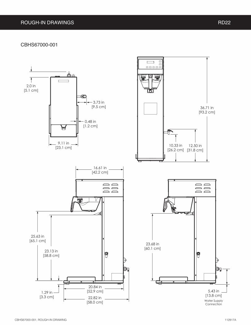
ROUGH-IN DRAWINGS RD22
CBHS67000-001
2.0 in[5.1 cm]
9.11 in[23.1 cm]
3.73 in[9.5 cm]
0.48 in[1.2 cm]
36.71 in[93.2 cm]
12.50 in[31.8 cm]
10.33 in[26.2 cm]
23.68 in[60.1 cm]
20.84 in[52.9 cm]
23.13 in[58.8 cm]
25.63 in[65.1 cm]
16.61 in[42.2 cm]
1.29 in[3.3 cm] 22.82 in
[58.0 cm]
5.43 in[13.8 cm]
Water Supply Connection
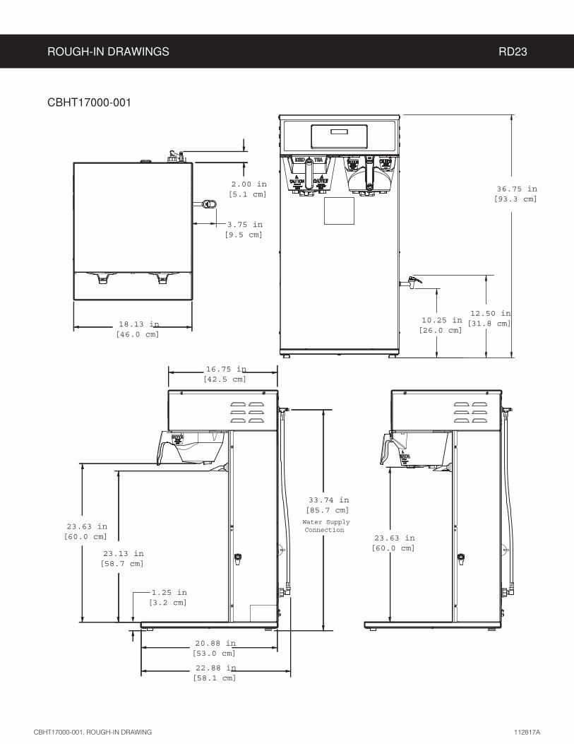
ROUGH-IN DRAWINGS RD23
CBHT17000-001
2.00 in[5.1 cm]
3.75 in[9.5 cm]
18.13 in[46.0 cm]
16.75 in[42.5 cm]
23.63 in[60.0 cm]
23.13 in[58.7 cm]
1.25 in[3.2 cm]
20.88 in[53.0 cm]
23.63 in[60.0 cm]
36.75 in[93.3 cm]
12.50 in[31.8 cm]10.25 in
[26.0 cm]
22.88 in[58.1 cm]
33.74 in[85.7 cm]
Water Supply Connection
ILLUSTRATED PARTS/RECOMMENDED PARTS IP16
14
8
27
22
31
32
4
29
6
11
3
28
1326
19
20
21
23
2
9
12
5
10
30 24
18
1
15
7
17
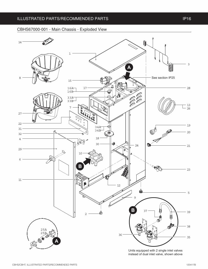
CBHS67000-001 - Main Chassis - Exploded View
A
B
See section IP25
16A16B
33A33B
34A34B
25A25B
Units equipped with 2 single inlet valves instead of dual inlet valve, shown above
37
3635
38
39
A
B

ILLUSTRATED PARTS/RECOMMENDED PARTS IP16
ITEM # PART # DESCRIPTION
1 WC-58117COVER, TOP ALPGT/D500GT/D60GT TLP/TCTS/CBS/GEMSS
2 WC-3503 LEG, 3/8”-16 STUD SCREW BUMPER
3 WC-13444 HARNESS, ADAPTER ASSY CBHVS
4 WC-43134O’RING, .426 X 9/16 O.D X .070 WALL EDPM TCTS
5 WC-3518 LEG, GLIDE 3/8”-16 STUD SCREW
6 WC-66079 SPOUT ASSY , DILUTION PLASTIC
7 WC-10007-102CONTROL MODULE UCM 120V CBHS/CBHT (NO ICED COFFEE)
8 WC-3398BREW CONE, ASSY STD TEA NON METAL W/BLU SPLASH POCKET
9 WC-8531 RAIL, BASE TCTD
10 WC-895-105 VALVE, INLET DUAL 120V 10W 2 GPM X .5 GPM
11 WC-8559RELAY, SOLID STATE 280V/40A W/ HEATSINK AND QUICK DISCONNECTS
12 WC-103SWITCH, TOGGLE NON-LIT DPST 25A 125/250VAC RESISTIVE
13 WC-5310 TUBE, 5/16 ID x 1/8W SILICONE GEN USE
14 WC-5231 COMPOUND, SILICONE 5 OZ
15 WC-37122 KIT, DUMP VALVE RIGHT
16A1 WC-2977K KIT, SPRAYHEAD FITTING METAL
16B2 WC-2977-101K KIT, SPRAYHEAD FITTING PLASTIC
17 WC-29044-101 SLEEVE, OVERFLOW
18 WC-29050 SPRAYHEAD, AMBER ADVANCED FLOW
19 WC-37255 KIT, DUAL VALVE WATER INLET
20 WC-1200 CORD, 14/3 SJTO 6’ BLK W/PLUG
21 WC-1412 CORD GRIP, 3/4” FOR METAL CORD TO .81”OD
22 WC-39846 LABEL, UCM OVERLAY COMBO SINGLE CURTIS
ITEM # PART # DESCRIPTION
11 WC-8559RELAY, SOLID STATE 280V/40A W/ HEATSINK AND QUICK DISCONNECTS
12 WC-103SWITCH, TOGGLE NON-LIT DPST 25A 125/250VAC RESISTIVE
13 WC-5310 TUBE, 5/16 ID x 1/8W SILICONE
14 WC-5231 COMPOUND, SILICONE 5 OZ
15 WC-37122 KIT, DUMP VALVE RIGHT
CBHS67000-001 Series - Recommended Parts to Stock
ITEM # PART # DESCRIPTION
23 WC-37252KIT, HOT WATER FAUCET REPLACEMENT ALPGT/D60GT/D500GT
24 WC-4308 WASHER, 1/2 ID INTRNL LCK, STL
25A WC-37132KIT, VALVE REPAIR USE ON WC-820WDR,WC-821WDR, WC-844WDR (OLDER UNITS)
25B WC-37132-101KIT, VALVE REPAIR FOR DELTROL WC-820WDR,WC-821WDR, WC-844WDR (NEWER UNITS)
26 WC-5350 TUBE, 1/2 ID x 1/8W SILICONE GEN USE
27 WC-3422BREW CONE,ASSY W/SPLASH POCKET BRWN STYLIZED HIGH VOLUME
28 WC-844-101VALVE, BY-PASS, NON-ADJUSTABLE WITH RESTRICTOR (WC-2945)
29 WC-61607 COVER, FRONT CBHVS
30 WC-4271 NUT, LOCK 1/2”-20 W/ NYLON INSERT PLATED
31 WC-38439 LABEL, FRONT HOT WATER TPS1S
32 WC-1416 PLUG, 1/2” HOLE
33A1 WC-4320O’RING, 0.487I.D.x 0.693OD x0.103CS BUNA-N #112
33B2 WC-43089GASKET, 1.00OD X .625 I.D. X .030 THK WHITE EPDM 70 SHORE
34A1 WC-4213 NUT, 5/8 LOCK PLATED
34B2 WC-4212-02 NUT, 5/8-18 JAM PLASTIC
35 WC-847VALVE, INLET 2 GPM 120V 10W GEN USE BROWN BODY
36 WC-12020 VALVE, INLET .5 GPM 120V 9W CB
37 WC-2401 ELBOW, 3/8 NPT X 1/4 FLRE PLTD PLATED
38 WC-2705 TEE, 1/4 X 1/4 FLARE X 3/8 NPT PLATED
39 WC-53074TUBING, NYLON BRAIDED FLEXIBLE 1/4 FLARE.250 ID .438 OD 6 3/4
ITEM # PART # DESCRIPTION
16A WC-2977K KIT, SPRAYHEAD FITTING METAL
18 WC-29050 SPRAYHEAD, AMBER ADVANCED FLOW
19 WC-37255 KIT, DUAL VALVE WATER INLET
26 WC-5350 TUBE, 1/2 ID x 1/8W SILICONE GEN USE
CBHS67000-001 - Main Chassis - Parts List
1Units built 05/15/17 and later.2

ILLUSTRATED PARTS/RECOMMENDED PARTS IP16
3
8
7
27
22
6
29
14
20
31
28
15
9
19
23
21
10
5
2
11
3217
18
4
30
24
12
1
CBHT17000-001 - Main Chassis - Exploded View
A
See section IP26
16A16B
33A33B
34A34B
1326
25A25B
AUnits equipped with 2 single inlet valves instead of dual inlet valve, shown above
38
38
37
36
35
B
B

ILLUSTRATED PARTS/RECOMMENDED PARTS IP16
ITEM # PART # DESCRIPTION
1 WC-5421COVER, TOP SS GEM-12D GEM-612ILD, TL9002, 312IL
2 WC-3503 LEG, 3/8”-16 STUD SCREW BUMPER
3 WC-13335-101 HARNESS ASSY, COMPLETE CBHVT
4 WC-43134O’RING, .426 X 9/16 O.D X .070 WALL EDPM TCTS
5 WC-3518 LEG, GLIDE 3/8”-16 STUD SCREW
6 WC-66079 SPOUT ASSY , DILUTION PLASTIC
7 WC-10007-102CONTROL MODULE UCM 120V CBHS/CBHT (NO ICED COFFEE)
8 WC-3398BREW CONE, ASSY STD TEA NON METAL W/BLU SPLASH POCKET
9 WC-53045TUBE ASSY, FLEXIBLE 1/4 FLARE SS/STL X 28.” LG NYLON BRAIDED
10 WC-895-104VALVE, INLET DUAL 120V 9W .53 GPM X .53 GPM
11 WC-8559RELAY, SOLID STATE 280V/40A W/ HEATSINK AND QUICK DISCONNECTS
12 WC-102SWITCH, TOGGLE NON-LIT SPST 15A 125/6A 250VAC RESISTIVE
13 WC-5310 TUBE, 5/16 ID x 1/8W SILICONE GEN USE
14 WC-5231 COMPOUND, SILICONE 5 OZ
15 WC-37122 KIT, DUMP VALVE RIGHT
16A1 WC-2977K KIT, SPRAYHEAD FITTING METAL
16B2 WC-2977-101K KIT, SPRAYHEAD FITTING PLASTIC
17 WC-29044-101 SLEEVE, OVERFLOW
18 WC-29050 SPRAYHEAD, AMBER ADVANCED FLOW
19 WC-37255 KIT, DUAL VALVE WATER INLET
20 WC-847VALVE, INLET 2 GPM 120V 10W GEN USE BROWN BODY
21 WC-1412 CORD GRIP, 3/4” FOR METAL CORD TO .81”OD
ITEM # PART # DESCRIPTION
11 WC-8559RELAY, SOLID STATE 280V/40A W/ HEATSINK AND QUICK DISCONNECTS
12 WC-102SWITCH, TOGGLE NON-LIT SPST 15A 125/6A 250VAC RESISTIVE
13 WC-5310 TUBE, 5/16 ID x 1/8W SILICONE
14 WC-5231 COMPOUND, SILICONE 5 OZ
15 WC-37122 KIT, DUMP VALVE RIGHT
16A WC-2977K KIT, SPRAYHEAD FITTING METAL
CBHT17000-001 Series - Recommended Parts to Stock
ITEM # PART # DESCRIPTION
22 WC-39845 LABEL, UCM OVERLAY COMBO TWIN CURTIS
23 WC-37252KIT, HOT WATER FAUCET REPLACEMENT ALPGT/D60GT/D500GT
24 WC-4308 WASHER, 1/2 ID INTRNL LCK, STL
25A WC-37132KIT, VALVE REPAIR USE ON WC-820WDR,WC-821WDR, WC-844WDR (OLDER UNITS)
25B WC-37132-101KIT, VALVE REPAIR FOR DELTROL WC-820WDR,WC-821WDR, WC-844WDR (NEWER UNITS)
26 WC-5350 TUBE, 1/2 ID x 1/8W SILICONE GEN USE
27 WC-3422BREW CONE,ASSY W/SPLASH POCKET BRWN STYLIZED HIGH VOLUME
28 WC-844-101VALVE, BY-PASS, NON-ADJUSTABLE WITH RESTRICTOR (WC-2945)
29 WC-61619 COVER, FRONT CBHVT
30 WC-4271 NUT, LOCK 1/2”-20 W/ NYLON INSERT PLATED
31 WC-2705 TEE, 1/4 X 1/4 FLARE X 3/8 NPT PLATED
32 WC-37121 KIT, DUMP VALVE LEFT
33A1 WC-4320O’RING, 0.487I.D.x 0.693OD x0.103CS BUNA-N #112
33B2 WC-43089GASKET, 1.00OD X .625 I.D. X .030 THK WHITE EPDM 70 SHORE
34A1 WC-4213 NUT, 5/8 LOCK PLATED
34B2 WC-4212-02 NUT, 5/8-18 JAM PLASTIC
35 WC-2401 ELBOW, 3/8 NPT X 1/4 FLRE PLTD PLATED
36 WC-2707 TEE, 1/4 X 1/4 FLARE X 3/8 NPT PLATED
37 WC-53074TUBING, NYLON BRAIDED FLEXIBLE 1/4 FLARE.250 ID .438 OD 6 3/4
38 WC-12020 VALVE, INLET .5 GPM 120V 9W CB
ITEM # PART # DESCRIPTION
18 WC-29050 SPRAYHEAD, AMBER ADVANCED FLOW
19 WC-37255 KIT, DUAL VALVE WATER INLET
20 WC-847VALVE, INLET 2 GPM 120V 10W GEN USE BROWN BODY
26 WC-5350 TUBE, 1/2 ID x 1/8W SILICONE GEN USE
32 WC-37121 KIT, DUMP VALVE LEFT
CBHT17000-001 - Main Chassis - Parts List
1Units built 05/15/17 and later.2
ILLUSTRATED PARTS/RECOMMENDED PARTS IP25
WC-62080 TANK ASSEMBLY, ILLUSTRATED PARTS/RECOMMENDED PARTS 090616NC
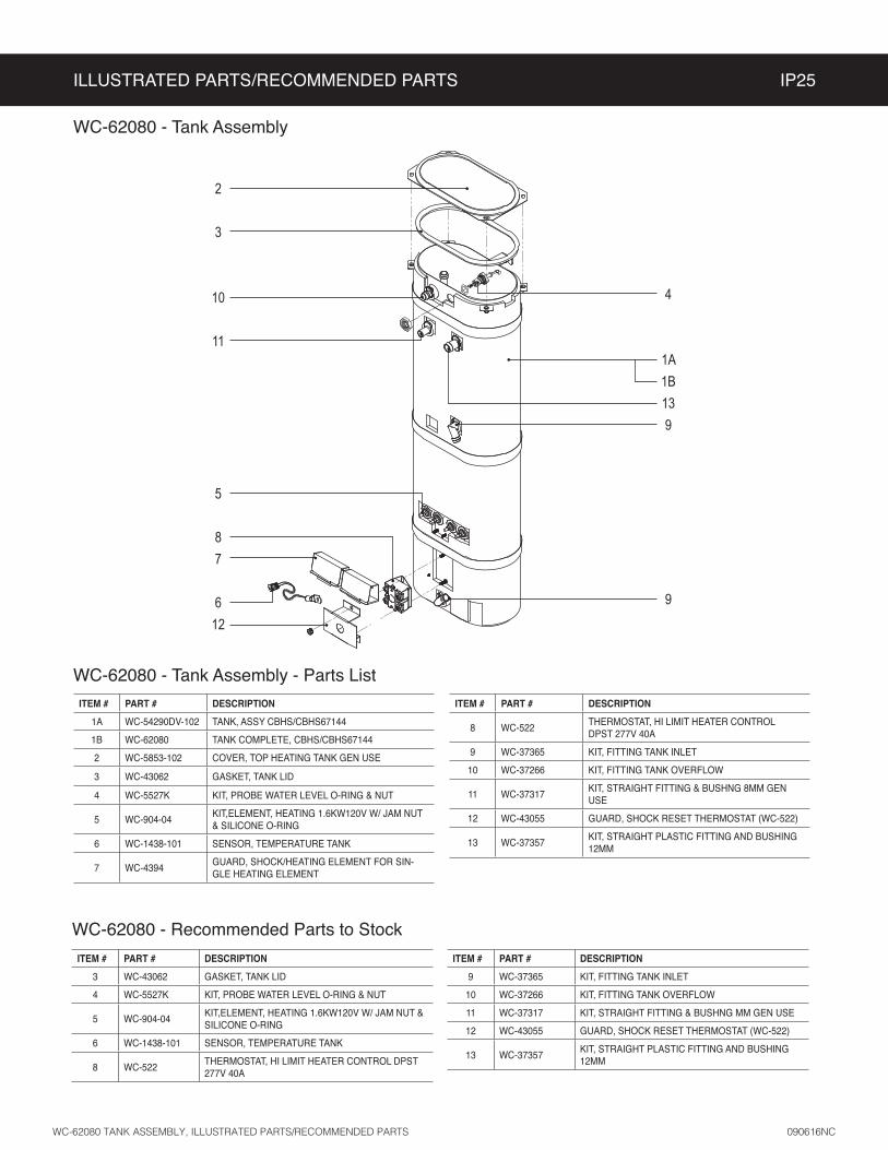
ITEM # PART # DESCRIPTION
1A WC-54290DV-102 TANK, ASSY CBHS/CBHS67144
1B WC-62080 TANK COMPLETE, CBHS/CBHS67144
2 WC-5853-102 COVER, TOP HEATING TANK GEN USE
3 WC-43062 GASKET, TANK LID
4 WC-5527K KIT, PROBE WATER LEVEL O-RING & NUT
5 WC-904-04KIT,ELEMENT, HEATING 1.6KW120V W/ JAM NUT & SILICONE O-RING
6 WC-1438-101 SENSOR, TEMPERATURE TANK
7 WC-4394GUARD, SHOCK/HEATING ELEMENT FOR SIN-GLE HEATING ELEMENT
ITEM # PART # DESCRIPTION
3 WC-43062 GASKET, TANK LID
4 WC-5527K KIT, PROBE WATER LEVEL O-RING & NUT
5 WC-904-04KIT,ELEMENT, HEATING 1.6KW120V W/ JAM NUT & SILICONE O-RING
6 WC-1438-101 SENSOR, TEMPERATURE TANK
8 WC-522THERMOSTAT, HI LIMIT HEATER CONTROL DPST 277V 40A
WC-62080 - Recommended Parts to Stock
ITEM # PART # DESCRIPTION
9 WC-37365 KIT, FITTING TANK INLET
10 WC-37266 KIT, FITTING TANK OVERFLOW
11 WC-37317 KIT, STRAIGHT FITTING & BUSHNG MM GEN USE
12 WC-43055 GUARD, SHOCK RESET THERMOSTAT (WC-522)
13 WC-37357KIT, STRAIGHT PLASTIC FITTING AND BUSHING 12MM
ITEM # PART # DESCRIPTION
8 WC-522THERMOSTAT, HI LIMIT HEATER CONTROL DPST 277V 40A
9 WC-37365 KIT, FITTING TANK INLET
10 WC-37266 KIT, FITTING TANK OVERFLOW
11 WC-37317KIT, STRAIGHT FITTING & BUSHNG 8MM GEN USE
12 WC-43055 GUARD, SHOCK RESET THERMOSTAT (WC-522)
13 WC-37357KIT, STRAIGHT PLASTIC FITTING AND BUSHING 12MM
WC-62080 - Tank Assembly
2
3
10
11
5
87
612
4
1A1B139
9
WC-62080 - Tank Assembly - Parts List

ILLUSTRATED PARTS/RECOMMENDED PARTS IP26
WC-62033 TANK ASSEMBLY, ILLUSTRATED PARTS/RECOMMENDED PARTS 090616NC
ITEM # PART # DESCRIPTION
1A WC-54287 TANK, ASSY TPS1T/GEMTS
1B WC-62033 TANK, COMPLETE GEMTS W/ULTEM FITTINGS
2 WC-37008 KIT, TANK LID ROUND (INCLUDES GASKET)
3 WC-37357KIT, STRAIGHT PLASTIC FITTING AND BUSHING 12MM
4 WC-5527K KIT, PROBE WATER LEVEL O-RING & NUT
5 WC-934-04KIT,ELEMENT HEATING 2.5KW 220V W/ JAM NUT & SILICONE WASHERS
6 WC-1438-101 SENSOR, TEMPERATURE TANK
ITEM # PART # DESCRIPTION
2 WC-37008 KIT, TANK LID ROUND (INCLUDES GASKET)
3 WC-37357KIT, STRAIGHT PLASTIC FITTING AND BUSHING 12MM
4 WC-5527K KIT, PROBE WATER LEVEL O-RING & NUT
5 WC-934-04KIT,ELEMENT HEATING 2.5KW 220V W/ JAM NUT & SILICONE WASHERS
6 WC-1438-101 SENSOR, TEMPERATURE TANK
WC-62033 - Recommended Parts to Stock
ITEM # PART # DESCRIPTION
8 WC-522THERMOSTAT, HI LIMIT HEATER CONTROL DPST 277V 40A
9 WC-37365 KIT, FITTING TANK INLET
10 WC-37266 KIT, FITTING TANK OVERFLOW
11 WC-37317 KIT, STRAIGHT FITTING & BUSHNG 8MM GEN USE
12 WC-43055 GUARD, SHOCK RESET THERMOSTAT (WC-522)
ITEM # PART # DESCRIPTION
7 WC-4382 GUARD, SHOCK HTNG ELMNT DOUBLE
8 WC-522THERMOSTAT, HI LIMIT HEATER CONTROL DPST 277V 40A
9 WC-37365 KIT, FITTING TANK INLET
10 WC-37266 KIT, FITTING TANK OVERFLOW
11 WC-37317 KIT, STRAIGHT FITTING & BUSHNG 8MM GEN USE
12 WC-43055 GUARD, SHOCK RESET THERMOSTAT (WC-522)
WC-62033 - Tank Assembly
2
10
3
11
7
68
12
4
1A1B9
5
9
WC-62033 - Tank Assembly - Parts List
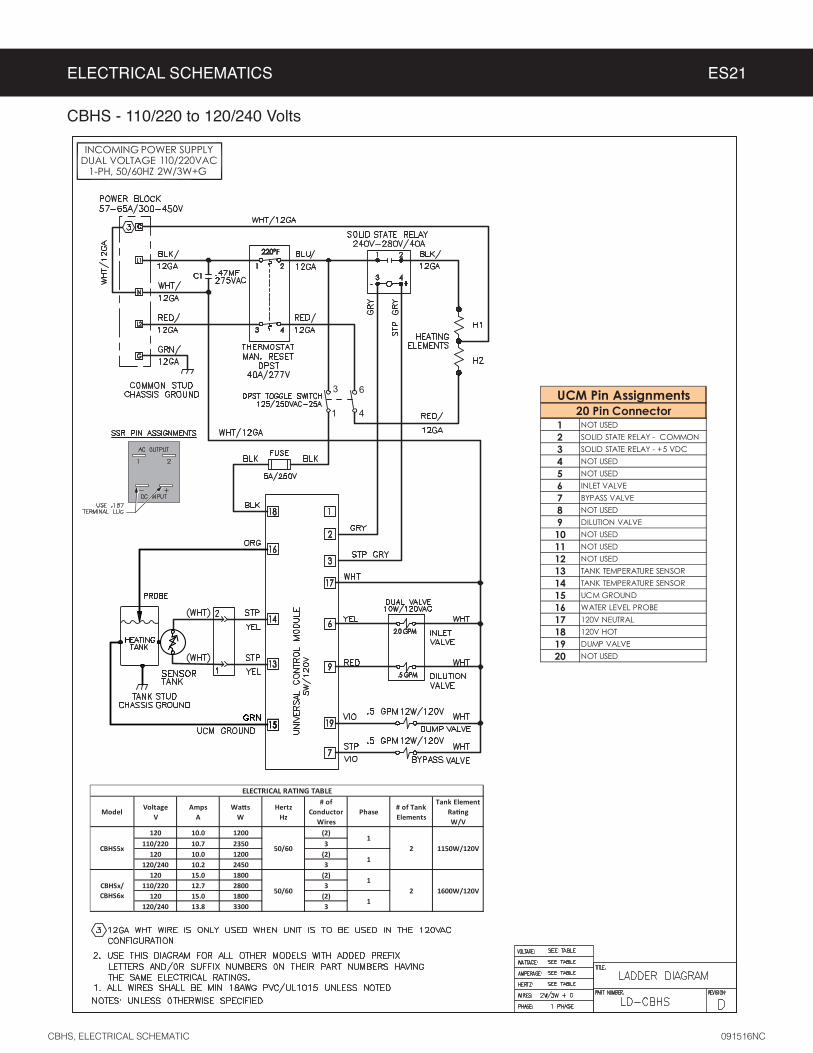
ELECTRICAL SCHEMATICS ES21
CBHS, ELECTRICAL SCHEMATIC 091516NC
CBHS - 110/220 to 120/240 Volts
1 NOT USED2 SOLID STATE RELAY - COMMON 3 SOLID STATE RELAY - +5 VDC4 NOT USED5 NOT USED6 INLET VALVE7 BYPASS VALVE8 NOT USED9 DILUTION VALVE10 NOT USED11 NOT USED12 NOT USED13 TANK TEMPERATURE SENSOR14 TANK TEMPERATURE SENSOR15 UCM GROUND16 WATER LEVEL PROBE17 120V NEUTRAL18 120V HOT19 DUMP VALVE20 NOT USED
UCM Pin Assignments20 Pin Connector
ModelVoltage
VAmps
AWa s
WHertz
Hz
# of Conductor
WiresPhase
# of Tank Elements
Tank Element Ra ng W/V
120 10.0 1200 (2)110/220 10.7 2350 3
120 10.0 1200 (2)120/240 10.2 2450 3
120 15.0 1800 (2)110/220 12.7 2800 3
120 15.0 1800 (2)120/240 13.8 3300 3
ELECTRICAL RATING TABLE
06/05x5SHBC1
2 1150W/120V1
CBHSx/ CBHS6x
50/601
2 1600W/120V1
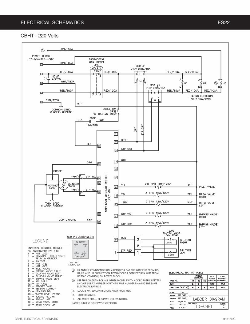
ELECTRICAL SCHEMATICS ES22
CBHT, ELECTRICAL SCHEMATIC 091516NC
CBHT - 220 Volts

WARNING:
Electric Shock Hazard -
Scald and Burn Hazard -
Troubleshooting Guidelines
• •
•
• .
Valve Test Procedure
in either direction
2
3
Water Not Hot Enough
2 replace the temperature sensor
Water Heats More Slowly Than Usual
2
TROUBLESHOOTING GUIDE TG5
IMPORTANT: always check all
Valve Test Procedure

TROUBLESHOOTING GUIDE TG40
Water Does Not Heat At All
• Check to see if the water level in the tank is in contact with the water level probe. If not, see Tank Does Not Fill. The water will not heat unless it is in contact with the probe.
• If the water heats, but is not hot enough, see Water Not Hot Enough.• If Ready to brew appears on the display, but the water is not hot, check the resistance across the leads of the
temperature sensor. If the resistance is less than 10 k and the water is not hot, replace the temperature sensor. If the sensor resistance is above 10 k when the water is cool, replace the universal control module (UCM).
If Heating... appears on the display, but the water is not hot, follow the steps below. The following steps are performed with the rear toggle switch in the ON position.
1 Check for power across the terminals of the heating element(s). If power is being supplied, remove the wires and check for an open heating element.
2 If there is no power to the element(s), trace the circuit back (using the ELECTRICAL SCHEMATIC) to the power
following step. On units having two SSRs, be sure to check both.
3 If there is power into a SSR, but not out, check for 5 Vdc (nominal*) across the + and - pins of the SSR(s). If there is 5 Vdc across the + and - pins of the SSR(s), but no (or low) output voltage at a SSR output terminal, replace the SSR. If 5 Vdc is not being supplied from the UCM, but Heating... appears on the display, check the wiring from the UCM to the SSR(s). If the wiring is OK, replace the UCM.
Water Too Hot (Boiling or Excessive Steaming)
1 If Over Temp Sensor or Ready to Brew appears on the display and the water is too hot, go to Over Temp Sensor Error Message.
2 If the display reads Heatingto the tank and that heat sink compound was used. A properly mounted sensor should have a resistance of around 7 k when the water is hot. If not, replace the sensor.
3 Check to see if the universal control module (UCM) constantly has +5 Vdc output (nominal) to the solid state relay (SSR), regardless of the resistance of the temperature sensor. If so, the UCM is probably bad.
4 If the UCM is working properly, check for a shorted SSR.
Over Temp Sensor Error Message
This error message indicates that the universal control module (UCM) has detected a water overheating problem. The UCM is reading a water temperature in the tank above 210ºF. If the water temperature is too hot, but Heating... appears on the display, see Water Too Hot. Once the malfunction causing the error is corrected, the error message must be cleared. To reset the brewer and return to normal operation, turn the toggle switch on the back of the brewer to the OFF position for 5 seconds, then back on.
1 Check for 5 Vdc (nominal) across the + and - pins of the solid state relay (SSRs). If no power is applied to the SSR and the heating elements are always on, replace the SSR. On units having two SSRs, check both.
2 Turn off power to the brewer and allow the water tank to cool. Once cool, turn power back on while monitoring the voltage across the + and - pins of the SSR(s). During normal operation, the voltage should be 5 Vdc, until the water is hot, then drop to below 1 Vdc. The UCM should be replaced if the voltage reads 5 Vdc constantly even though Ready to brew or Over Temp Sensor appears on the display.
3 If the UCM is operating normally, check for a false over-temp error caused by the temperature sensor. Check the resistance across the leads of the temperature sensor. If the resistance is less than 10 k when the water is cool, replace the temperature sensor.
G3 BREWERS WITH SSR, TROUBLESHOOTING GUIDE-200F 120417NC
IMPORTANT: Before proceeding, make sure that the control panel temperature is adjusted to compensate for higher elevations. The factory setting is 200°F. Reduce the temperature setting two degrees for every 1000 feet of elevation above 4000 feet.
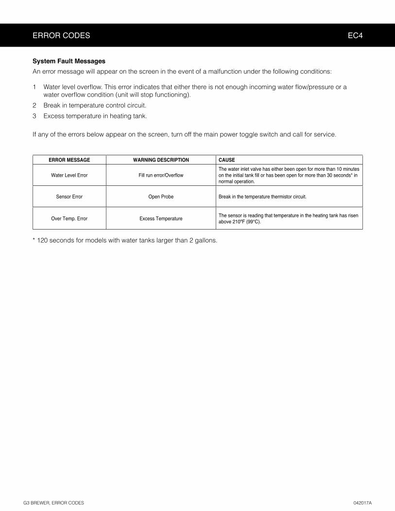
ERROR CODES EC4
ERROR MESSAGE WARNING DESCRIPTION CAUSE
Water Level Error
System Fault Messages
An error message will appear on the screen in the event of a malfunction under the following conditions:
1
2
3
G3 BREWER, ERROR CODES 042017A

PRODUCT WARRANTY PW1
3 years, parts and labor, from original date of purchase on digital control boards21
CONDITIONS & EXCEPTIONS
• Adjustments and cleaning: The resetting of safety thermostats and circuit breakers, programming and temperature adjustments are the responsibility of the equipment owner. The owner is responsible for proper cleaning and regular maintenance of this equipment.
• Replacement of items subject to normal use and wear: This shall include, but is not limited to, spray heads, faucets, light bulbs, shear disks, “O” rings, gaskets, silicone tubing, silicone elbows, canister assemblies, whipper chambers and plates, mixing bowls, agitation assemblies and whipper propellers.
• Improper operation of equipment: The equipment must be used for its designed and intended purpose and function.• Improper installation of equipment: This equipment must be installed by a professional technician and must comply with all local elec-
trical, mechanical and plumbing codes.• Improper voltage: Equipment must be installed at the voltage stated on the serial plate supplied with this equipment.• Improper water supply: • Damaged in transit: Equipment damaged in transit is the responsibility of the freight company and a claim should be made with the carrier. • Abuse or neglect (including failure to periodically clean or remove lime accumulations): The manufacturer is not responsible for
variation in equipment operation due to excessive lime or local water conditions. The equipment must be maintained according to the manufacturer’s recommendations.
Repairs and/or Replacements
Return Merchandise Authorization (RMA):All returned equipment must be properly re-packaged in the
original carton and received by Curtis within 45 days following the issuance of a RMA.NO UNITS OR PARTS WILL BE ACCEPTED WITHOUT A RETURN MERCHANDISE AUTHORIZATION
(RMA). THE RMA NUMBER MUST BE MARKED ON THE CARTON OR SHIPPING LABEL. All warranty claims must be submitted within 60 days of service. Invoices will not be processed or accepted without a RMA number. Any defective parts must be returned in order for warranty invoices to be processed and approved.