g3m - omronomronfs.omron.com/en_us/ecb/products/pdf/en-g3m.pdf · g3m-@@@pl: 1 ms max. g3m-@@@p:...
TRANSCRIPT
1
G3M
G3MSolid State Relays
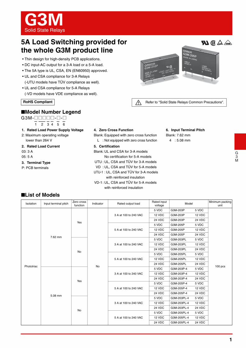
5A Load Switching provided forthe whole G3M product line• Thin design for high-density PCB applications.
• DC input-AC output for a 3-A load or a 5-A load.
• The 5A type is UL, CSA, EN (EN60950) approved.
• UL and CSA compliance for 3-A Relays
(-UTU models have TÜV compliance as well).
• UL and CSA compliance for 5-A Relays
(-VD models have VDE compliance as well).
■Model Number Legend
■List of Models
RoHS Compliant Refer to "Solid State Relays Common Precautions".
Isolation Input terminal pitchZero cross
functionIndicator Rated output load
Rated input voltage
ModelMinimum packing
unit
Phototriac
7.62 mm
Yes
No
3 A at 100 to 240 VAC
5 VDC G3M-203P 5 VDC
100 pcs
12 VDC G3M-203P 12 VDC
24 VDC G3M-203P 24 VDC
5 A at 100 to 240 VAC
5 VDC G3M-205P 5 VDC
12 VDC G3M-205P 12 VDC
24 VDC G3M-205P 24 VDC
No
3 A at 100 to 240 VAC
5 VDC G3M-203PL 5 VDC
12 VDC G3M-203PL 12 VDC
24 VDC G3M-203PL 24 VDC
5 A at 100 to 240 VAC
5 VDC G3M-205PL 5 VDC
12 VDC G3M-205PL 12 VDC
24 VDC G3M-205PL 24 VDC
5.08 mm
Yes
3 A at 100 to 240 VAC
5 VDC G3M-203P-4 5 VDC
12 VDC G3M-203P-4 12 VDC
24 VDC G3M-203P-4 24 VDC
5 A at 100 to 240 VAC
5 VDC G3M-205P-4 5 VDC
12 VDC G3M-205P-4 12 VDC
24 VDC G3M-205P-4 24 VDC
No
3 A at 100 to 240 VAC
5 VDC G3M-203PL-4 5 VDC
12 VDC G3M-203PL-4 12 VDC
24 VDC G3M-203PL-4 24 VDC
5 A at 100 to 240 VAC
5 VDC G3M-205PL-4 5 VDC
12 VDC G3M-205PL-4 12 VDC
24 VDC G3M-205PL-4 24 VDC
G3M-@@@@@ -@ -@— — — — — —1 2 3 4 5 6
1. Rated Load Power Supply Voltage2: Maximum operating voltage
lower than 264 V
2. Rated Load Current03: 3 A
05: 5 A
3. Terminal TypeP: PCB terminals
4. Zero Cross FunctionBlank: Equipped with zero cross function
L : Not equipped with zero cross function
5. CertificationBlank: UL and CSA for 3-A models
No certification for 5-A models
UTU : UL, CSA and TÜV for 3-A models
VD : UL, CSA and TÜV for 5-A models
UTU-1 : UL, CSA and TÜV for 3-A models
with reinforced insulation
VD-1: UL, CSA and TÜV for 5-A models
with reinforced insulation
6. Input Terminal PitchBlank: 7.62 mm
4 : 5.08 mm
2
G3M Solid State Relays
G3M
■RatingsInput (Each model has 5-VDC, 12-VDC, and 24-VDC input versions.) Output
* The load current varies depending on the ambient temperature.Refer to Load Current vs. Ambient Temperature under Engineering Data.
■Characteristics
Rated voltage
Operating voltage ImpedanceMust operate voltage level
Must release voltage level
5 VDC 4 to 6 VDC 300 Ω ±20% 4 VDC max.
1 VDC min.12 VDC 9.6 to 14.4 VDC 800 Ω ±20% 9.6 VDC max.
24 VDC 19.2 to 28.8 VDC 1.6 kΩ ±20% 19.2 VDC max.
Item Rated voltage
Applicable load
Model Load voltage range Load current Inrush current
G3M-203P(L)100 to
240 VAC75 to 264 VAC
0.1 to 3 A *45 A(60 Hz, 1 cycle)
G3M-205P(L) 0.1 to 5 A *60 A(60Hz, 1 cycle)
Item Model G3M-203P(L) G3M-205P(L)
Operate timeG3M-@@@PL: 1 ms max. G3M-@@@P: 1/2 of load power source cycle + 1 ms max.
Release time 1/2 of load power source cycle + 1 ms max.
Output ON voltage drop 1.6 V (RMS) max.
Leakage current 1.5 mA max. (at 200 VAC)
Insulation resistance 1,000 MΩ min. (at 500 VDC)
Dielectric strength 2,500 VAC, 50/60 Hz for 1 min between input and output
Vibration resistance 10 to 55 to 10 Hz, 0.75-mm single amplitude (1.5-mm double amplitude)
Shock resistance 1,000 m/s2
Ambient operating temperature −30°C to 80°C (with no icing or condensation)
Ambient operating humidity 45% to 85%RH
Storage temperature −30°C to 100°C (with no icing or condensation)
Weight Approx. 15 g Approx. 25 g

3
G3M Solid State Relays
G3M
■Engineering Data
• Thirty Relays are soldered to the PCB at each given spacing.
• Continuous power.
Load Current vs. Ambient Temperature
One Cycle Surge Current: Non-repetitiveNon-repetitive (Reduce the current under the dotted line of the impulse withstand current for repetitive operation)
● Operating Environment Precautions
The rated value for the ambient operating temperature of the SSR is determined under conditions when there is no heat build-up. (Left graph)Note that it is necessary to reduce the load current as the ambient temperature of the SSR may increase due to operating conditions.(Figure below is an example of the G3M-205P(L) model)When using the SSR, design the system to allow heat dissipation sufficient to stay below the Load Current vs. Ambient Temperature characteristic curve.
Load Current vs. Ambient Temperature (Close Mounting)G3M-205 Series (5-A Load)<X direction> <Y direction> <Z direction>
6
5
4
3
2
1
0.5
0
Ambient temperature (°C)100 80 60 40 20 25 0 -20-30
G3M-205P(L)
G3M-203P(L)
Load
cur
rent
(A
)
Energized time (ms)
G3M-205P(L)
5,000 1,000 500 200 100 50 30 10
50
70
60
40
30
20
10 In
rush
pea
k cu
rren
t (A
)
G3M-203P(L)
6
5
4
3
2
1
0
Ambient temperature (°C)100 80 60 40 20 25 0 −20 −30
0.6A L=7.62
1.5A L=12.7
2.0A L=20.37
Load
cur
rent
(A
) 6
5
4
3
2
1
0 100 80 60 40 20 25 0 −20 −30
0.8A L=7.62
1.8A L=12.7
2.5A L=20.37
Ambient temperature (°C)
Load
cur
rent
(A
) 6
5
4
3
2
1
0 100 80 60 40 20 25 0 −20 −30
0.8A L=7.62
1.8A L=12.7
2.5A L=20.37
Ambient temperature (°C)
Load
cur
rent
(A
)
LL
10 pcs.
3 pcs.
Top
Bottom
L L
3 pcs.
10 pcs.
Top
Bottom
L L
10 pcs.Top
Bottom

4
G3M Solid State Relays
G3M
■Dimensions (Unit: mm)
■Precautions• Please refer to “Solid State Relays Common Precautions” for correct use.
2.54 Four, 1.2 dia. holes
2.54
G3M-203P(L)G3M-203P(L)-4
Terminal Arrangement (BOTTOM VIEW)
PCB Dimensions (BOTTOM VIEW)G3M-203P(L)
G3M-203P(L)-4
40 max. 9 max.
20 max.
4
7.62 4±2
12.7 10.16
0.7 0.4
1.5(5.08)*
*Input terminal pitch for models ending in "-4" is 5.08 mm.
2.54 Four, 1.2 dia. holes
2.54
Load power supply
Load
1 2
LOADINPUT
Input voltage
3 +- 4
+-
2.54 Four, 1.2 dia. holes
2.54
G3M-205P(L)G3M-205P(L)-4
Terminal Arrangement (BOTTOM VIEW)
PCB Dimensions (BOTTOM VIEW)G3M-205P(L)
G3M-205P(L)-4
40 max.
*Input terminal pitch for models ending in "-4" is 5.08 mm.
7.6±0.2
25 max.
4
7.624±2
12.710.16
0.7 0.4
1.65(5.08)*
2.54 Four, 1.2 dia. holes
2.54
Load power supply
Load
1 2
LOADINPUT
Input voltage
3 +- 4
+-

5
G3M Solid State Relays
G3M
Cat. No. K073-E1-071014(0207)(O)
OMRON CorporationElectronic and Mechanical Components Company Contact: www.omron.com/ecb
Note: Do not use this document to operate the Unit.
• Application examples provided in this document are for reference only. In actual applications, confirm equipment functions and safety before using the product. • Consult your OMRON representative before using the product under conditions which are not described in the manual or applying the product to nuclear control systems, railroad
systems, aviation systems, vehicles, combustion systems, medical equipment, amusement machines, safety equipment, and other systems or equipment that may have a serious influence on lives and property if used improperly. Make sure that the ratings and performance characteristics of the product provide a margin of safety for the system or equipment, and be sure to provide the system or equipment with double safety mechanisms.