g6s g3s protocol v2.24 - equipment.skypatrol.com
TRANSCRIPT

SP4600/SP3600 Protocol V2.24
Copyright © 2013

SP4600/SP3600 Protocol
2 / 123
Foreword
■ Skypatrol provides this document to describe the communication protocol format between Skypatrol vehicle terminal, mobile terminal (Cell
phone), and communication control center, with the aim of providing a basis for engineers to design a uniform control commands for specific
products. The Intended audiences of this document are Skypatrol product development engineers.
■In this document, vehicle terminal’s control and connection structure is descried. Data packet and command packet formats between vehicle
terminal, mobile terminal, communication commands and their scopes are clearly defied. Privilege of different connection approaches (SMS,
Cable, and GPRS/Wi-Fi) and their functions are clearly defined.
Copyright
■This document is a confidential document. Any individual or organization is strictly prohibited to reproduction, use or disclosure to the third
party without permission. Otherwise, we hold the right to investigate the legal responsibility.
Company address:
3055 NW 84th Avenue, Miami FL 33122
Tel: +1.786.331.3300
Fax: +1.786.477.4567
E-mail: [email protected]
Website: www.skypatrol.com

SP4600/SP3600 Protocol
3 / 123
Change log
Firmware version Change
V1.01 to V1.02 1,Fix the issue that when parking and GPS from unfix to fix device dose not report.
2,Extend ACC detection time.
3,Add acceleration magnitude value in event data that related to 2D accelerate meter.
4,Modify move to stop duration time to 2 seconds, stop to move duration to 3 seconds, when testing please disable MOT,
and set the first parameter of BMS as 2.
5,Manual event clearance report will carry ETT.
6,Fix over speed event issue.
7,OUT1 level will save the last status after rebooting.
8,Modify DIS minimum value to 10 meters.
9,All the events except over speed in ESM default changed to DISABLE.
10,Geo-fence does not change do not test with this version.
11,Modify move/stop judgment algorithm of accelerate meter.
12,Fix bug that device cannot upgrade the firmware
13,Modify parking judgment algorithm, modify BMS, add duration time parameter for stop judgment.
14,Modify crossing/speed/time parameter relationship algorithm in Geo-fence.
15,Add 1WIRE data process.
16,Use level1 optimization process.
17,Use level0 optimization process for Geo-fence related feature.
18,Modify serial port maximum transmit size to 320 bytes.
19,Fix duplicated "//" in ETD content via SMS and Geo-fence data bug.
20,Fix wrong date format im event report.
21,Fix 1WIRE main data mask is always enabled issued in HEX data string.
22,Clear Geo-fence event report when Geo-fence status is changed.
23,Under private hour mode only specify event reports position information.
24,Remove power saving mode.
25,Optimize standard driving library in use only.
26,Add acceleration magnitude value in harsh behavior report via SMS.
27,Fix bug that causing by remote upgrade.
28,All features use level default optimization except Geo-fence.
29,Fix CRC verify on serial port data transmission.
30,Fix bug in combination event.
31,Fix bug in command list profile trigger condition.
32,Fix bug that command via serial port only works on second time.
33,Fix bug on command GOF.
34,Add Geo-fence data ID and data length in Geo-fence event HEX data string.
35,Modify workday mask in command PVM to HEX.
36,Add device model query command PTY.
37,Add feature that GSM module reset automatically if cannot register to network within 10 minutes.
38,Add time parameter to command ATH and PTH.
39,Modify command EOB, digital output will have different output mode according to event status and event clearance.
SP4600/SP3600 Protocol
4 / 123
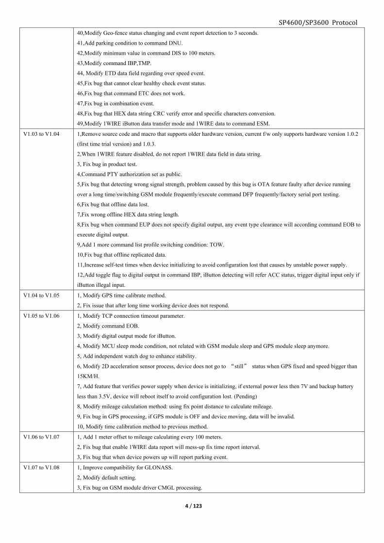
40,Modify Geo-fence status changing and event report detection to 3 seconds.
41,Add parking condition to command DNU.
42,Modify minimum value in command DIS to 100 meters.
43,Modify command IBP,TMP.
44, Modify ETD data field regarding over speed event.
45,Fix bug that cannot clear healthy check event status.
46,Fix bug that command ETC does not work.
47,Fix bug in combination event.
48,Fix bug that HEX data string CRC verify error and specific characters conversion.
49,Modify 1WIRE iButton data transfer mode and 1WIRE data to command ESM.
V1.03 to V1.04 1,Remove source code and macro that supports older hardware version, current f/w only supports hardware version 1.0.2
(first time trial version) and 1.0.3.
2,When 1WIRE feature disabled, do not report 1WIRE data field in data string.
3, Fix bug in product test.
4,Command PTY authorization set as public.
5,Fix bug that detecting wrong signal strength, problem caused by this bug is OTA feature faulty after device running
over a long time/switching GSM module frequently/execute command DFP frequently/factory serial port testing.
6,Fix bug that offline data lost.
7,Fix wrong offline HEX data string length.
8,Fix bug when command EUP does not specify digital output, any event type clearance will according command EOB to
execute digital output.
9,Add 1 more command list profile switching condition: TOW.
10,Fix bug that offline replicated data.
11,Increase self-test times when device initializing to avoid configuration lost that causes by unstable power supply.
12,Add toggle flag to digital output in command IBP, iButton detecting will refer ACC status, trigger digital input only if
iButton illegal input.
V1.04 to V1.05 1, Modify GPS time calibrate method.
2, Fix issue that after long time working device does not respond.
V1.05 to V1.06 1, Modify TCP connection timeout parameter.
2, Modify command EOB.
3, Modify digital output mode for iButton.
4, Modify MCU sleep mode condition, not related with GSM module sleep and GPS module sleep anymore.
5, Add independent watch dog to enhance stability.
6, Modify 2D acceleration sensor process, device does not go to “still” status when GPS fixed and speed bigger than
15KM/H.
7, Add feature that verifies power supply when device is initializing, if external power less then 7V and backup battery
less than 3.5V, device will reboot itself to avoid configuration lost. (Pending)
8, Modify mileage calculation method: using fix point distance to calculate mileage.
9, Fix bug in GPS processing, if GPS module is OFF and device moving, data will be invalid.
10, Modify time calibration method to previous method.
V1.06 to V1.07 1, Add 1 meter offset to mileage calculating every 100 meters.
2, Fix bug that enable 1WIRE data report will mess-up fix time report interval.
3, Fix bug that when device powers up will report parking event.
V1.07 to V1.08 1, Improve compatibility for GLONASS.
2, Modify default setting.
3, Fix bug on GSM module driver CMGL processing.

SP4600/SP3600 Protocol
5 / 123
4, Improve SPI flash offline data processing method.
5, Modify on commands: SVR, BSV,EPM, UGP
V1.08 to V2.00 1, Only supports hardware version V1.05 or higher.
2, Bootloader version equal or higher than V1.0.3.
V2.00 to V2.01 1, Only supports hardware version V1.05 or higher.
2, Modify GPS power saving mode, “stop to move” will wake up GPS instantly.
3, Geo fence scan rate changes to 20 ones per second.
4, Modify PRO GPS command.
5, Fix bug on command MOT.
V2.01 to V2.02 1, Only supports hardware version V1.05 or higher.
2, Modify command EPM, add EPM;3 mode, this mode is to set G6S uses external data source to process as GPS data.
3, Modify command UGP, add UGP;6 mode, this mode is to print real time packet on debug windows.
4, Modify resistor for AD1 input, Geo fence scan rate changes back to 5 ones per second.
5, Add option for server ACK via TCP.
6, Fix bug on command GOF, UFM.
V2.02 to V2.03 1, Only supports hardware version V1.05 or higher.
2, Fix bug on Telit module regarding data generating.
3, Fix bug on command APL.
4, Fix bug on 1WIRE link.
5, Modify command VER, add suffix “-T” and “-U” for indication of differ GPS module.
V2.03 to V2.04 1, Only supports hardware version V1.05 or higher.
2, Fix bug on GPS driver.
3, Adjust time sync on U-blox module.
4, Add license request for GPRS connectivity and command CHC for license status check.
5, Add firmware encryption for copyright protection.
6, Modify command FWU, user name and password are not requested.
7, Fix bug that if SVP set as “O”, Fixed distance and angle do not work.
8, Modify command EUP, add “Report to GPRS or SMS”.
9, Add command SVT.
10, Modify command EPM.
11, Add command GFC.
12, Add command IBC.
13, Modify SMS message, CSQ changes to GSM, ACIN changes to Ext_Pwr.
14, Modify command ERL, add “Valid period”.
15, Command DFP will not reset setting of command NAM.
16, Modify default setting of command OAS.
17, Add packet type indicator in data string.
V2.04 to V2.05 1, Add command EUC.
2, Renew packet example on chapter 4.3.7 and 4.4.7.
V2.05 to V2.06 1, Add balance notification command BLS.
2, Move command DOO to public command list.
3, Add GSM Anti-jamming configuration command JMP.
4, Command SPO is able to set without enabled over speed event in command ESM.
5, Add command FRS.
6, Fix bug on iButton ID reading.
V2.06 to V2.07 1, Fix bug on command BLS.

SP4600/SP3600 Protocol
6 / 123
2, Add command TSP.
V2.07 to V2.08 1, Modify offline data packing method.
2, Fix bug on command ACM, UCM, SWL.
3, Add new command BDU0, BDU1.
V2.08 to V2.09 1, Optimize ADC driver to have more stable voltage measure
2, Fix bug on returned parameter of commands ERL, HTM, VOE, EFM
3, Fix bug on Tow event, and refer GPS speed for this event
4, Assign command NAM to user phone and SMS server to use
5, Fix bug on offline GPRS packet
6, Add command AIR to set AD1 measure scale range
7, Fix bug on combination events
8, Modify command FRS
9, Fix bug on setting profile switching, OTA and profile switching will no able to execute simultaneously
10, Add command SIM to query current SIM card number
11, Add command EPT to change report interval from serial port according to ACC status
12, Fix bug on AGPS
V2.09 to V2.10 1, Fix bug on long SMS
2, Fix bug on offline packet report
3, Optimize GPS position filter
4, Fix bug incoming call freeze when under UGP;3 mode
5, Optimize AGPS
6, Sync with GSM time when GPS invalid
V2.10 to V2.11 1, Show viewable satellites in data packet when GPS is not fixed.
2, Modify command FWU.
3, Allow time adjustment manually.
4, When GPS data is not valid its data in packet will stuffing with 0.
5, Modify command IBP, output actives (low level) when ACC OFF.
6, Add event “illegal ibutton”.
7, Modify command IBO, add command IBE, IBS.
8, Modify command EPM.
9, Add command HUP, command PUP.
10, Add command GAM, command GVR, command.
11, GSM module wakes up when under moving + data transmitting request.
12, Add command ITS
13, Modify command JMP
14, Improve GPS filter algorithm.
15, Improve AGPS.
16, Data verify for 1wire temp sensor.
17, Improve GPS time sync algorithm.
V2.11 to V2.12 1, Fix bug that command GPO is not working for GSM module.
2, Fix bug timeline error when set as “offline data prior”.
3, Fix bug on EPM2.
4, Fix bug on offline packet.
5, Fix bug unable to pickup hotline incoming call when MDT is connected.
6, Modify command PSS0.
V2.12 to V2.13 1, Fix bug about GLONASS time reset to all 0 after power on/power reset.

SP4600/SP3600 Protocol
7 / 123
2, GPS HDOP higher than preset value, speed will be 0.
3, Fix bug on MEI in offline packet.
4, Modify command PSS1
5, Modify SMS notification of OTA upgrade to “Same Firmware” when device current firmware version is latest
6, Improve ibutton reading performance.
V2.13 to V2.14 1, Modify command EPM.
V2.14 to V2.17 1.Add RPD command and recover the parameter except specific commands to default value;
2.Add CTF command——support to export the current configuration file to the file, and upload via ymodem ;
3.Add YGF;6 to support to upload the last exported current configuration file;
V2.17 to V2.18 1.Modify IBO command format;
2.Add DOR command:support DO OUT1status saving,and recover to the last status when regain the power;
V2.18 to V2.23 1.Add SPTcommand;2. Add LCS command;3.Add RCS command;4.Add RCP command;
V2.23 to V2.24
1. Add CLScommand;2.Add PSTcommand; 3.Modify HBIcommand;4.Add low voltage sleeping event under the situation with battery power supply;5.Modify error of data status of the geo-fence event;

8 / 123
1. General structure
# Participant Command authorization Communication medium Format
1 Computer OEM/Administrator USB cable ASCII
2 User phone User SMS ASCII
3 SMS server Administrator SMS ASCII
4 GPRS server Administrator
Command
communication
via GPRS network
GPRS(TCP/UDP) ASCII
Device packet
via GPRS network
to server
GPRS(TCP/UDP)
ASCII/HEX
Command authorization:
■3 levels of authorization are available for different command list in APPENDIX chapter.
OEM: For agent/distributor, all commands are valid for this authorization.
Admin: For administrator, by default admin command list and public command list are valid for this authorization.
OEM authorization is able to use command ACM to customize command list for admin authorization.
User: For user command list only and only via SMS, by default user command list is valid for this authorization. OEM/Admin authorization is
able to use command UCM to customize command list for user.
■Authorization level: OEM > Admin > User
SP4600/SP3600 Protocol

9 / 123
2. Connect with computer
■To use commands in this document to configure and interactive with device:
>Connect device with computer via USB cable and run serial communication software.
>Input ^O (Ctrl + O) 3 times in a row, you will find “Please Input Password:[CR][LF]” on software window.
>Input OEM configuration password “0123456789” (default) and press enter, if the Password is correct, you will find “[LF] Cable Port In OEM
Mode [CR][LF]” on software window.
>Use commands in this document to configure the device.
3. General definition of command3.1. General symbol * Command head
, Command separator
: Only in device reply message, between command word and its parameter
; Parameter separator, or separator between command word and parameter
# Command tail
e.g.:
■Command without parameter (Query command)
Send:
Command word1,Command word2
Reply:
Command word1:Parameter1; Parameter2; Parameter3,Command word2: Parameter1; Parameter2; Parameter3
■Command with parameter (Configuration tool command)
Send:
Command word1;Parameter1;Parameter2;Parameter3,Command word2: Parameter1; Parameter2; Parameter3
Reply:
Command word1:Parameter1; Parameter2; Parameter3,Command word2: Parameter1; Parameter2; Parameter3
■SMS server (Admin) and GPRS server command format
Send:
*GS06, Command word1;Parameter1;Parameter2;Parameter3,Command word2: Parameter1; Parameter2; Parameter3#
Reply:
*GS06,Device ID, Command word1:Parameter1; Parameter2; Parameter3,Command word2: Parameter1; Parameter2; Parameter3#
3.2. Data conversion
■Under 2 circumstances that the data needs to be converted:
>HEX format with "F8" “1B” in data field except packet head and tail.
>ASCII format with “* , ; ( #” in data field except head and tail.
SP4600/SP3600 Protocol

SP4600/SP3600 Protocol
10 / 123
3.2.1. HEX Format
■If there is "1B" or "F8" in the data field of packet, device will convert them before sending to server.
Conversion method:
Value XOR “1B”, to get data "XX", then add "IB" in the front of "XX", to become 1BXX
e.g.: "F8" XOR “1B” equals ” E3" , "F8" will convert to "IBE3".
Before F8 1B
After 1BE3 1B00
Note: Server must reserves the above process when it receives data from device to have the genuine data.
3.2.2. ASCII Format
■If there is symbol “* , ; ( #” in the data field of packet, device will convert them before sending to server.
Conversion method:
Add "(" in front of those symbols.
Before * , ; ( #
After (* (, (; (( (#
Note: Server must reserves the above process when it receives data from device to have the genuine data.
3.3. Data verify >Verification adopts “CRC16 – CCITT standard”.
>Device verifies the data before data conversion.
>Generate polynomial method: X16 + X12 + X5+1.
>Base type: 1021.
>Standard reference: ISO in HDLC, ITU x.25, v. 34 / v. 41 / v. 42, the PPP – FCS.
Note: Do the conversion before CRC
3.4. Data packing process of device >Device generates raw data.
>CRC verifies raw data.
>Data conversion.
>Packing data by adding packet head and packet tail.
Note: For the server processing, must remove packet head/tail ->conversion->parsing as peer protocol
4. Regular packet>SMS server packet length is 230bytes maximum.
>GPRS server packet length is 384bytes maximum.
>If device switches to international roaming status, it will send a regular packet to the server.
>If device switches from GPS unfixed to GPS fixed status, it will send a regular packet to the server.
■Under below circumstances, device will send packet to GPRS server and SMS server proactively:
>According to its configuration (e.g.: fixed time report, fix cornering, fixed distance report).
>Events being triggered.
>Device forwards SMS from another phone number to user/server.
SP4600/SP3600 Protocol
11 / 123
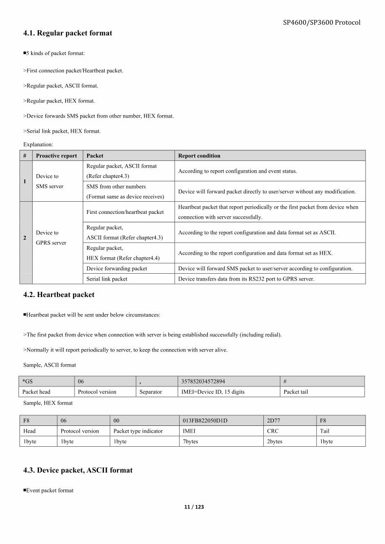
4.1. Regular packet format
■5 kinds of packet format:
>First connection packet/Heartbeat packet.
>Regular packet, ASCII format.
>Regular packet, HEX format.
>Device forwards SMS packet from other number, HEX format.
>Serial link packet, HEX format.
Explanation:
# Proactive report Packet Report condition
1 Device to
SMS server
Regular packet, ASCII format
(Refer chapter4.3) According to report configuration and event status.
SMS from other numbers
(Format same as device receives) Device will forward packet directly to user/server without any modification.
2 Device to
GPRS server
First connection/heartbeat packet Heartbeat packet that report periodically or the first packet from device when
connection with server successfully.
Regular packet,
ASCII format (Refer chapter4.3) According to the report configuration and data format set as ASCII.
Regular packet,
HEX format (Refer chapter4.4) According to the report configuration and data format set as HEX.
Device forwarding packet Device will forward SMS packet to user/server according to configuration.
Serial link packet Device transfers data from its RS232 port to GPRS server.
4.2. Heartbeat packet
■Heartbeat packet will be sent under below circumstances:
>The first packet from device when connection with server is being established successfully (including redial).
>Normally it will report periodically to server, to keep the connection with server alive.
Sample, ASCII format
Sample, HEX format
F8 06 00 013FB822050D1D 2D77 F8
Head Protocol version Packet type indicator IMEI CRC Tail
1byte 1byte 1byte 7bytes 2bytes 1byte
4.3. Device packet, ASCII format
■Event packet format
*GS 06 , 357852034572894 #
Packet head Protocol version Separator IMEI=Device ID, 15 digits Packet tail

12 / 123
■Non-event packet format
e.g.: *GS06, 351535053999223,235833280213,86
<Packet head and protocol version>,<Device ID>,<Time and date>,<Event type ID>
Note1: By order of “Hour/Minute/Second/Day/Month/Year”, 2bytes for each
If time/date is invalid this field will be “000000000000”.
Note2: HEX format, bit7 is defined as “event status identifier”, “bit6 to bit0” is defines as “event ID”.
0x9c means ACC OFF to ON event.
(Convert it to decimal format and find its specific meaning in the chapter9 “Event list”).
4.3.1. Data field
>Regular packet data field length is customize-able via command ADM.
Format: <Main data type mask>:<Sub data type mask>
<Sub data type mask>: Command SDM is used to customized sub data of each main data type, e.g.:
SDM1;7F to select all sub data of GPS:
GPS: A;8;N23.164351;E113.428515;0;0;37;0.85;0.35
SDM1;4F to select partial sub data of GPS:
GPS: A;8;N23.164351;E113.428515;0;0;;;0.35
<Main data type mask>
Main data type ID Explanation Bit as “0” Bit as “1”
SYS System data Not report Report
GPS GPS data Not report Report
GSM GSM data Not report Report
COT COT data Not report Report
ADC AD data Not report Report
DTT Device status data Not report Report
IWD 1WIRE data Not report Report
*GS 06 , 351535053999389 , 235833280213 , 9C , <SYS>,<GPS>,
<GSM>,<COT>,
<ADC>,<DTT>,
<IWD>,<ETD>
#
Packet
head
Protocol
version
IMEI=Device ID,
15 digits
Time and date
*Note1
Event
type ID
*Note2
Data field Packet
tail
*GS 06 , 351535053999389 , 235833280213 , , <SYS>,<GPS>,
<GSM>,<COT>,
<ADC>,<DTT>,
<IWD>
#
Packet
head
Protocol
version
IMEI=Device ID,
15 digits
Time and date
*Note1
Null Data field
Packet
tail
SP4600/SP3600 Protocol

SP4600/SP3600 Protocol
13 / 123
ETD Event data Not report Report
4.3.2. SYS: System data
■e.g.: SYS:G6S;V1.01;V1.01
Format:
<System data ID>:<Device name>;<Firmware version>;<Hardware version>
SYS: G6S;V1.01;V1.01
System data identifier <Device name>;<Firmware version>;<Hardware version>
■SYS data field length is customize-able via command SDM0
4.3.3. GPS: GPS data
■e.g.: GPS:A;8;N23.164351;E113.428515;0;0;37;0.85;0.35
Format:
<GPS data identifier> :<GPS fix flag>;<Valid satellite number>;
<Latitude>;<Longitude>;<Speed>;<Azimuth>;<Altitude>;<HDOP>;<VDOP>
■GPS data field length is customize-able via command SDM1
■GPS sub-data table, command SMD1 to configure.
HEX, 2bytes maximum, each bit represents one kind of GPS sub-data type.
“0”: not report this sub-data type.
“1”: report this sub-data type.
Bit Sub-data type Bit as 0 Bit as 1 Data length, ASCII Data length, HEX
0 GPS fix flag
Not report Report =1byte 1byte
Valid satellite number <=2bytes
1 Latitude
Not report Report 10bytes 8bytes
Longitude 11bytes
2 Speed Not report Report <=3bytes 2bytes
3 Azimuth Not report Report <=3bytes 2bytes
4 Latitude Not report Report <=5 bytes 2bytes
5 HDOP Not report Report <=5 bytes 2bytes
6 VDOP Not report Report <=5 bytes 2bytes
7 Reserved
GPS: A; 4; N23.164351; E113.428515; 0; 0; 37; 0.85; 0.35
GPS data
identifier
GPS
fix flag,
“A”
means
fixed,
“V”
means
unfixed
Valid
satellite
number
Latitude,
“N” means
north,
“S” means
south.
Longitude,
“E” means east,
“W” means
west.
Speed Azimuth Altitude,
range is
“-9999 to
+9999”, unit
is meter.
(HDOP)
Horizontal
Dilution of
Precision,
range is
“0 to 99.99”,
decimal.
(VDOP)
Vertical
dilution of
precision,
range is
“0 to
99.99”,
decimal.

SP4600/SP3600 Protocol
14 / 123
4.3.4. GSM: GSM data
■e.g.: GSM:5;4;460;0;2731;BB41;-82;460;0;2731;436E;-81;460;0;2731;436D;-94
Format:
<GSM data identifier>:<Registration status>;<GSM signal strength>;<MCC1>;<MNC1>;
<LAC1>;<CID1>;<RSSI1>;<MCC2>;<MNC2>;<LAC2>;<CID2>;<RSSI2>…<MCC7>;<MNC7>;<LAC7>;<CID7>;<RSSI7>
■If GPS is not fixed or invalid, its data field will be replaced by GSM data, GSM data including GSM network registration status/signal
strength/base stations information, maximum 7 GSM towers information to carry.
ID Value Explanation Remark
1 GSM: GSM data identifier
2 5; REG, registration status, range is “0 to 5” Refer APPENDIX
3 4; Signal strength, range is “0 to 5” Refer APPENDIX
4 460; Decimal,3 digits or 5 digits, if invalid this field will be “65535” Mobile country code
5 0; Decimal,1 digit or 2 digits or 5 digits, if invalid this field will be
“65535”
Mobile network code
6 2731; LAC1, HEX, range is “0 to FFFF”, if invalid this field will be “FFFF” GSM(main) base station zone code
7 40F4; CID1,HEX, range is “0 to FFFF”, if invalid this field will be “FFFF” GSM(main) base station identifier
8 -57; RSSI1,Decimal, Signal strength, unit is dBm Signal strength
9 460; MCC2, Decimal, 3 digits or 5 digits, if invalid this field will be “65536” Mobile country code
10 0; MNC2, Decimal, 1 digit or 2 digits or 5 digits, if invalid this field will be
“65535”
Mobile network code
11 2503; LAC2, HEX, range is “0 to FFFF”, if invalid this field will be “FFFF” Base station zone code
12 962C; CID2, HEX, range is “0 to FFFF”, if invalid this field will be “FFFF” Base station identifier
13 -71; RSSI2, Decimal, Signal strength, unit is dBm Signal strength
14 460; MCC3, Decimal, 3 digits or 5 digits, if invalid this field will be “65536” Mobile country code
15 0; MNC3,Decimal,1 digit or 2 digits or 5 digits, if invalid this field will be
“65535”
Mobile network code
16 2731; LAC3, HEX, range is “0 to FFFF”, if invalid this field will be “FFFF” Base station zone code
17 40F3; CID3, HEX, range is “0 to FFFF”, if invalid this field will be “FFFF” Base station identifier
18 -83; RSSI3, Decimal, signal strength, unit is dBm Signal strength
Note: if MCC, MNC are “65535”, LAC, CID are “FFFF”, it indicates device fails to register to GSM network.
■APPENDIX
REG value
REG Explanation SMS/Voice/GPRS connectivity
0 Fail to register, device is not trying to register to any mobile network ×
1 Register successfully √
2 Fail to register, but device is trying to register to mobile network again ×
3 Register intention is being rejected by mobile network ×
4 Unknown reason ×
5 Register to roaming network successfully √
CSQ value
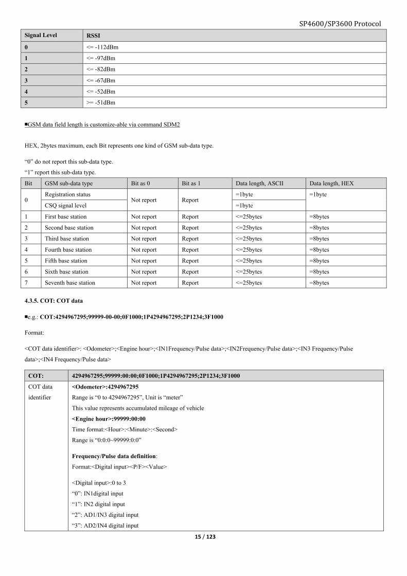
15 / 123
Signal Level RSSI
0 <= -112dBm
1 <= -97dBm
2 <= -82dBm
3 <= -67dBm
4 <= -52dBm
5 >= -51dBm
■GSM data field length is customize-able via command SDM2
HEX, 2bytes maximum, each Bit represents one kind of GSM sub-data type.
“0” do not report this sub-data type.
“1” report this sub-data type.
Bit GSM sub-data type Bit as 0 Bit as 1 Data length, ASCII Data length, HEX
0 Registration status
Not report Report =1byte =1byte
CSQ signal level =1byte
1 First base station Not report Report <=25bytes =8bytes
2 Second base station Not report Report <=25bytes =8bytes
3 Third base station Not report Report <=25bytes =8bytes
4 Fourth base station Not report Report <=25bytes =8bytes
5 Fifth base station Not report Report <=25bytes =8bytes
6 Sixth base station Not report Report <=25bytes =8bytes
7 Seventh base station Not report Report <=25bytes =8bytes
4.3.5. COT: COT data
■e.g.: COT:4294967295;99999-00-00;0F1000;1P4294967295;2P1234;3F1000
Format:
<COT data identifier>: <Odometer>;<Engine hour>;<IN1Frequency/Pulse data>;<IN2Frequency/Pulse data>;<IN3 Frequency/Pulse
data>;<IN4 Frequency/Pulse data>
COT: 4294967295;99999:00:00;0F1000;1P4294967295;2P1234;3F1000
COT data
identifier
<Odometer>:4294967295
Range is “0 to 4294967295”, Unit is “meter”
This value represents accumulated mileage of vehicle
<Engine hour>:99999:00:00
Time format:<Hour>:<Minute>:<Second>
Range is “0:0:0~99999:0:0”
Frequency/Pulse data definition:
Format:<Digital input><P/F><Value>
<Digital input>:0 to 3
“0”: IN1digital input
“1”: IN2 digital input
“2”: AD1/IN3 digital input
“3”: AD2/IN4 digital input
SP4600/SP3600 Protocol

SP4600/SP3600 Protocol
16 / 123
<P/F>:
“P”:Pulse
”F”:Frequency, unit is “Hz”
e.g.: ”0F10000”
”0” means digital input1
“F” means Frequency
■ COT data field length is customize-able via command SDM3
4.3.6. ADC: Analog to digital Converter data
■e.g.: ADC:12.60;3.99;10.00;10.00
Format:
<AD data identifier>:< External power supply voltage>;< Backup battery voltage>;
<ADC1 input voltage>;<ADC2 input voltage>
ADC: 12.60; 3.99; 10.00; 10.00
AD data
identifier
External power supply voltage
value, unit is “V”
Backup battery voltage
value, unit is “V”
ADC1 input voltage
value, unit is “V”
ADC2 input voltage value, unit
is “V”
■ADC data field length is customize-able via command SDM4
HEX, 2 bytes maximum, each bit represents one kind of GSM sub-data type.
“0” do not report this sub-data type,
“1” report this sub-data type.
Bit Sub-data type Bit as 0 Bit as 1 Data length, ASCII Data length, HEX
0 External power supply voltage Not report Report <=5bytes =2bytes
1 Backup battery voltage Not report Report <=5bytes =2bytes
2 ADC1 voltage Not report Report <=5bytes =2bytes
3 ADC2 voltage Not report Report <=5bytes =2bytes
4 Reserved
5 Reserved
6 Reserved
7 Reserved
4.3.7. DTT: Device status data
e.g.: DTT: FFFFFFFF;FF;FFFFFFFFFFFFFFFFFFFFFFFFFFFFFF;FFFFFFFFF;FFFFFFFFFFFFFFFF;FF
Format:
<Device status data identifier>:<Device status>;<I/O status>;<Number 0 to 119 Geo-fence status>;
<Number 120 to 155 Geo-fence status>;<Event status>;<Packet type indicator>
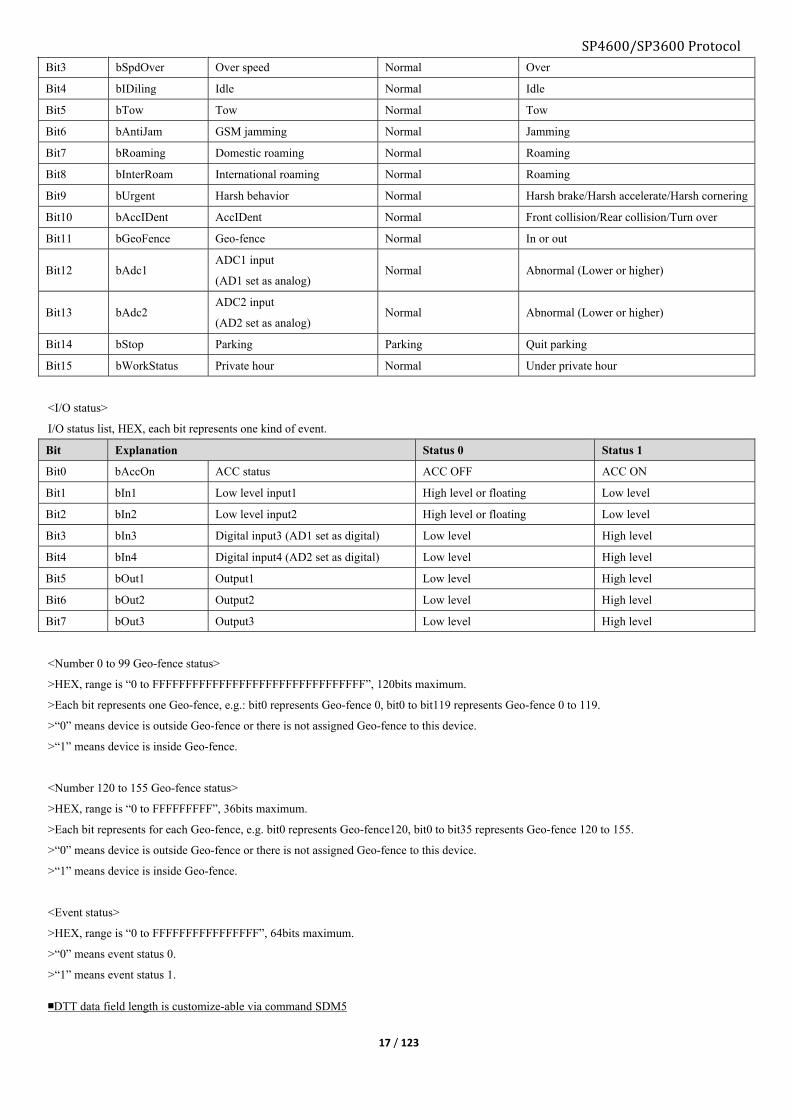
<Device status>
Device status list, HEX, each bit represents one kind of event.
Bit Explanation Status 0 Status 1
Bit0 bExtPwr External power supply Normal Lower or higher
Bit1 bInterBat Backup battery Normal Lower or higher
Bit2 bMoving Moving Stop Move
SP4600/SP3600 Protocol
17 / 123
Bit3 bSpdOver Over speed Normal Over
Bit4 bIDiling Idle Normal Idle
Bit5 bTow Tow Normal Tow
Bit6 bAntiJam GSM jamming Normal Jamming
Bit7 bRoaming Domestic roaming Normal Roaming
Bit8 bInterRoam International roaming Normal Roaming
Bit9 bUrgent Harsh behavior Normal Harsh brake/Harsh accelerate/Harsh cornering
Bit10 bAccIDent AccIDent Normal Front collision/Rear collision/Turn over
Bit11 bGeoFence Geo-fence Normal In or out
Bit12 bAdc1 ADC1 input
(AD1 set as analog) Normal Abnormal (Lower or higher)
Bit13 bAdc2 ADC2 input
(AD2 set as analog) Normal Abnormal (Lower or higher)
Bit14 bStop Parking Parking Quit parking
Bit15 bWorkStatus Private hour Normal Under private hour
<I/O status>
I/O status list, HEX, each bit represents one kind of event.
Bit Explanation Status 0 Status 1
Bit0 bAccOn ACC status ACC OFF ACC ON
Bit1 bIn1 Low level input1 High level or floating Low level
Bit2 bIn2 Low level input2 High level or floating Low level
Bit3 bIn3 Digital input3 (AD1 set as digital) Low level High level
Bit4 bIn4 Digital input4 (AD2 set as digital) Low level High level
Bit5 bOut1 Output1 Low level High level
Bit6 bOut2 Output2 Low level High level
Bit7 bOut3 Output3 Low level High level
<Number 0 to 99 Geo-fence status>
>HEX, range is “0 to FFFFFFFFFFFFFFFFFFFFFFFFFFFFFFFF”, 120bits maximum.
>Each bit represents one Geo-fence, e.g.: bit0 represents Geo-fence 0, bit0 to bit119 represents Geo-fence 0 to 119.
>“0” means device is outside Geo-fence or there is not assigned Geo-fence to this device.
>“1” means device is inside Geo-fence.
<Number 120 to 155 Geo-fence status>
>HEX, range is “0 to FFFFFFFFF”, 36bits maximum.
>Each bit represents for each Geo-fence, e.g. bit0 represents Geo-fence120, bit0 to bit35 represents Geo-fence 120 to 155.
>“0” means device is outside Geo-fence or there is not assigned Geo-fence to this device.
>“1” means device is inside Geo-fence.
<Event status>
>HEX, range is “0 to FFFFFFFFFFFFFFFF”, 64bits maximum.
>“0” means event status 0.
>“1” means event status 1.
■DTT data field length is customize-able via command SDM5

SP4600/SP3600 Protocol
18 / 123
<Packet type indicator>
>Indicates the cause of the reported packet.
>HEX, 2bytes
Bit Definition
0 Undefined
1 Periodical report
2 Fixed distance
3 Fixed angle
4 PRQ request
5 Under moving status, GPS from unfix to fix
6 Under international roaming
7 Renew APN or server settings
8 iButton triggered
4.3.8. 1WD: 1WIRE data
■e.g.: IWD:0;0;000133B29;1;1;3400012038C21;100
Format:
<1WIRE data identifier>:<Data ID>;<Data type>;<Data field>;<Data ID>;<Data type>;<Data field>
<Data type>
>”0” means 1WIRE input is iButton
>”1” means 1WIRE input is temperature sensor
<Data field>
>Serial number of iButton or serial number of temperature sensor and current temperature
IWD: 0; 0; 000133B29 1; 1; 3400012038C21 100
1WIRE data
identifier
Data ID Data
Type, “0” means
iButton
Data field, serial
number of iButton
Data
ID
Data
Type, “1” means
temperature
sensor
Serial number of
temperature sensor
Temperature
value
4.3.9. ETD: ETD data
■e.g.: ETD:11;30
Format:
<Event data identifier>:<data>…
ETD: 11; 30;
Event data identifier Meaning varied depending on event Meaning varied depending on event
Event data will be varied depending on event type
Event name Format Explanation
Over speed ETD:<Speed> <Speed>:
GPS based speed when event is triggered, unit is “km/h”

SP4600/SP3600 Protocol
19 / 123
Geo-fence ETD:<Time>;
<Speed>;
<Geo-fence number>;
<Status>
<Time>: Local time when Geo-fence event is triggered, 235833280213 format is
HHMMSSDDMMYY
<Speed>: Speed when Geo-fence event is triggered, unit is “km/h”.
<Geo-fence number>: Geo-fence number that is triggered.
<Status>:
bit1:
“1” means inside Geo-fence
“0” means outside Geo-fence
bit0:
“1” means beyond the preset speed range
“0” means within the preset speed range
Note: Maximum 5 Geo-fences data to carry
External power
supply event
/AD1 voltage
event
/AD2 voltage
event
ETD:
<voltage value>
<Voltage value>: Voltage value when event is triggered, unit is “V”
Health check
report
ETD:<Status> HEX:
Bit Explanation Status 0 Status 1
bit0 Socket1 connection status Disconnected Connected
bit1 Socket2 connection status Disconnected Connected
bit2 Socket3 connection status Disconnected Connected
bit3 Socket4 connection status Disconnected Connected
bit4 Socket5 connection status Disconnected Connected
bit5 Motion sensor status Abnormal Normal
bit6 Flash storages status Abnormal Normal
bit7 Vibration sensor Stop Vibrate
Harsh brake
/Harsh accelerate
/Harsh cornering
/Front collision
/Rear collision
/Turnover
ETD:<Parameter1>;<Pa
rameter2>
<Parameter1>: X axis acceleration magnitude value, float string (format %5.2f).
<Parameter2>: Y axis acceleration magnitude value, float string (format %5.2f).
X axis: Heading direction, positive value means brake, minus value means acceleration.
Y axis: Positive value means left cornering, minus value means right cornering.
1WIRE event:
Serial number of
iButton
/Temperature
value
ETD:<Data ID>;<Data
type>;<Data field>
<Device ID>: Serial number
<Device type>:
“0” means iButton, “1” means temperature sensor.
<Data field>:
Serial number of iButton or temperature sensor serial number and temperature value.
■Event data field length is customize-able via command SDM7
4.4. Device packet, HEX format

SP4600/SP3600 Protocol
20 / 123
Event packet format:
<Packet head><Protocol version><Packet type ID><Device ID><Time and date><Event ID><Main data ID
mask><SYS><GPS><GSM><COT><ADC><DTT><IWD><ETD><CRC verify><Packet tail>
Non-event packet, not carrying ”<Event ID> and <ETD>”
<Packet head><Protocol version><Packet type ID><Device ID><Time and date><Main data ID
mask><SYS><GPS><GSM><COT><ADC><DTT><IWD><CRC verify><Packet tail>
Packet format:
Packet
head
Protocol
version
Packet
type ID
HEX,
Device ID
Time and
date
Event
ID
Main data
mask
Data field CRC
verify
Packet
tail
F8 06 41 013FB822
050D1D
153AA8A6 9C 00FF <SYS><GPS><GSM>
<COT><ADC><DTT>
<IWD><ETD>
2D77 F8
1byte 1byte 1byte 7bytes 4bytes 1byte 2bytes Not fixed 2bytes 1byte
<Packet type ID>
HEX, packet type identifier.
Bit7:
“0” means long format, G6S only supports this format.
“1” means short format.
Bit6:
“0" means non-event packet
“1” means event packet, with data type <ETD>.
“Bit0-Bit5”:
“1” means device packet.
“2” means SMS forwarding packet.
Note: Packet type ID = 0x00 please refer chapter 4.2
<Device ID>
HEX, 7bytes fixed, device IMEI.
<Time and date>
4bytes unsigned integer data, high byte ahead, start from year 2000, Jan.1 00:00:00.
e.g.: HEX data “195A7F9E” converts to decimal is 425361310 seconds, which means 2013-06-64 03:55:10
<Event ID>
HEX, 1byte fixed.
Bit7 represents “Device status flag”.
“Bit6 to Bit0” represents “Event ID”, need to convert from HEX to decimal and find its definition in chapter9 “Event list”. e.g.: “0x9C”
represents event “ACC ON to OFF”.
Note: Non-event packet does not carry this field.
<Main data type mask>
HEX, 2bytes fixed.

21 / 123
SP4600/SP3600 Protocol Each bit represents each type of data, “1” means reporting this type of sub-data, “0” means not reporting this type of sub-data.
e.g.: “0x3B” converts to binary is “0011 1011”, which means only report <SYS><GPS><COT><ADC><DTT>
4.4.1. Data field
■Data field data length is customize-able via command ADM.
Format: “<Data length1><data1><data2><Data length1>data1><data2>…”
Main data mask, HEX, 2bytes
Bit Main data type Explanation
Bit definition
Bit as 0 Bit as 1
0 SYS System data Not report Report
1 GPS GPS data Not report Report
2 GSM GSM data Not report Report
3 COT COT data Not report Report
4 ADC Analog to digital converter data Not report Report
5 DTT Device status data Not report Report
6 IWD 1WIRE data Not report Report
7 ETD Event data Not report Report
8 Reserved Reserved
9 Reserved Reserved
10 Reserved Reserved
11 Reserved Reserved
12 Reserved Reserved
13 Reserved Reserved
14 Reserved Reserved
15 Reserved Reserved
4.4.2. SYS: System data
Format:
11 03473653 1556312E3030 265668312E3032
(In ASCII: G6S V1.00 Vh1.02)
<System data length><Sub-data ID and data length ><Sub-data field>…
11 03 473653 1556312E3030
SYS data length 0 3 473653 1 5 56312E3030
Sub-data ID Sub-data Length Sub-data field Sub-data ID Sub-data Length Sub-data field
1byte 1byte Not fixed 1byte Not fixed
<Sub-data ID and length>
1byte fixed, High 4bits represents sub-data type ID, and low 4bits represents sub-data length
“System data” sub-data type list
Sub-data ID Sub-data type Data length, ASCII Data length, HEX
0 Device name <=15Bytes <=15Bytes

SP4600/SP3600 Protocol
22 / 123
1 Firmware version <=8Bytes <=8Bytes
2 Hardware version <=8Bytes <=8Bytes
4.4.3. GPS: GPS data
Format:
15 007F 48 016175DD 06C2C8E8 0000 0000 004B 007C 007D
(In ASCII: GPS:A;8;N23.164381;E113.428712;0;0;75;1.24;1.25)
<GPS data length><GPS sub-data mask><Fix sign and valid satellite number>
<Coordinate><Speed><Azimuth><Altitude><HDOP><VDOP>
Content Length Explanation
15 1byte GPS data length, ”15” means 21bytes
007F 2bytes Sub-data mask, current is SDM1:003F, refer below table for further information
48 1 byte Fix flag and valid satellite number.
Bit0-bit4: Valid satellite number
Bit5-Bit6: GPS fix flag, “0” not fixed, “1” 2D fixed, “2” 3D fixed.
016175DD 8bytes Latitude
4bytes signed integer, HEX, high byte ahead.
Positive represents north-latitude, minus represents south-latitude.
E.g.: 0x016175DD, convert to decimal 23164381, divided by 1000000, which means 23.164381 degree
north-latitude.
06C2C8E8 Longitude
4bytes signed integer, HEX, high byte ahead.
Positive represents east-longitude, minus represents west-longitude
E.g.: 0x06C2C8E8, convert to decimal 113428712, divided by 1000000, which means 113.428712 degree
east-longitude
Note: For a minus value in HEX format (highest bit 1) covert to decimal the suggested procedure is:
e.g. 0xFCB3EC58
step1: invert each bit, 0 becomes 1, and 1 becomes 0
~FCB3EC58 = 034C13A7
Step2: plus 1
034C13A7 + 1 = 034C13A8
Step3:
034C13A8h = 55317416d/1000000 =-55.317416 degree
003C 2bytes Speed
2bytes signed integer, HEX, “0x003C” converts to decimal is “60”, which means speed is 60 km/h.
0000 2bytes Azimuth
2bytes unsigned, HEX
004B 2bytes Altitude
2bytes signed integer, HEX, high byte ahead.
“0x004B” converts to decimal is “75”, range is “-9999 to +9999”, unit is “meter”

SP4600/SP3600 Protocol
23 / 123
007C 2bytes <HDOP> Horizontal Dilution Of Precision
2bytes unsigned integer, HEX, high byte ahead.
E.g.: 0x007C, convert to decimal 124, divided by 100, which means 1.24
Rang is 0 to 99.99
007D 2bytes <VDOP> Vertical Dilution Of Precision
2bytes unsigned integer, HEX, high byte ahead.
E.g.: 0x007D, convert to decimal 125, divided by 100, which means 1.25
Rang is 0 to 99.99
4.4.4. GSM: GSM data
Format:
1A 0F 14 1CC000 2503 962C 40 1CC000 2731 40F4 56 1CC000 2731 BB42 66
(In ASCII: GSM:1;4;460;0;2503;962C;-64;460;0;2731;40F4;-86;460;0;2731;BB42;-102)
<GSM data length><Sub-data mask><Register status and signal strength><MCC1 and MNC1>
<LAC1><CID1><RSSI1><MCC2 and MNC2><LAC2><CID2><RSSI2><…>
<MCC1 and MNC1 >: Fixed 3bytes, “Bit0-Bit11” represents MNC1, “Bit12-Bit23” represents MCC1.
Content Length Explanation
1A 1byte GSM data field length, ”0A” is 10bytes
0F 1byte Sub-data mask
14 1byte Register status and signal strength, high 4bits represents network register status, low 4bits represents signal
strength.
1CC000 3byte <MCC1 “mobile country code” and MNC1 “mobile network code”>
2503 2byte <LAC1> : GSM main base station zone code
HEX, converts to decimal is “9475”
962C 2byte < CID1>: GSM main base station ID
HEX, converts to decimal is “38444”
40 1byte <RSSI1>: GSM signal strength
HEX, converts to decimal is “64”, which means strength is “-64dBm”.
1CC000 3byte <MCC2: GSM mobile country code” and MNC2: mobile network code>
2731 2byte <LAC2>: GSM main base station zone code
HEX, converts to decimal is “10033”
40F4 2byte < CID2>: GSM main base station ID
HEX, converts to decimal is “16628”
56 1byte <RSSI2>: GSM signal strength
HEX, converts to decimal is “86”, which means strength is “-86dBm”.
1CC000 3byte <MCC3: GSM mobile country code” and MNC3: mobile network code>
2731 2byte <LAC3>: GSM main base station zone code
HEX, converts to decimal is “10033”
BB42 2byte < CID3>: GSM main base station ID
HEX, converts to decimal is “47938”
66 1byte <RSSI3>: GSM signal strength
HEX, converts to decimal is “102”, which means strength is “-102dBm”.
4.4.5. COT: COT data

SP4600/SP3600 Protocol
24 / 123
Format:
0B 0203E8 1297C2 24200003E8
(In ASCII format: COT:1000;10:47:30;0P1000)
<COT data length><Sub-data ID and data length><Sub-data field>…
0B 02 03E8 12 97C2 24 2000 03E8
COT
data
length
0 2 03E8 1 2 97C2 2 4 2 000 03E8
Sub-data
ID
Sub-data
length
Sub-data
field
Sub-data
ID
Sub-data
length
Sub-data
field
Sub-data
ID
Sub-data
length
Packet
type
Sub-data
field
1byte 1byte Unfixed 1byte Unfixed 1byte High 4
bits
Low 28
bits
<COT data field length>:
“0B” means COT data field length is 11bytes (convert to decimal).
<Sub data ID and length>: 1byte
“Bit4-Bit7”: Sub-data type identifier
“Bit0-bit3”: Sub-data type length
Note: Frequency/Pulse data: High 4bits represents data type, “1” for frequency, “2” for pulse.
Data must converts from HEX to decimal.
e.g.: “53 1000 00FF” means DI4 input(AD2/IN4)frequency is ”255 Hz”
“COT data” Sub-data type ID
Sub-data type ID Sub-data type Data length, ASCII Data length, HEX
0 Mileage <=10Bytes <=5Bytes
1 Engine hour <=10Bytes <=5Bytes
2 DI1 input, frequency/pulse data <=11Bytes <=5Bytes
3 DI2 input, frequency/pulse data <=11Bytes <=5Bytes
4 DI3 (AD1/IN3) input, frequency/pulse data <=11Bytes <=5Bytes
5 DI4 (AD2/IN4) input, frequency/pulse data <=11Bytes <=5Bytes
Mileage:
HEX, convert to decimal, unit is “meter”. e.g.: “0x03E8” convert to decimal is “1000”, which means 1000 meters.
Engine hour:
HEX, convert to decimal, unit is “second”. e.g.: “0x97C2” convert to decimal is “38850”, which means 38850 seconds (10H:47M:30S)
4.4.6. AD: AD data
Format:
080320120823243208
<AD data length><ID +Value>…
08 0320 1208 2324 3208
AD data length 0 320 1 208 2 324 3 208
Sub-data
ID
Sub-data
field Sub-data
ID
Sub-data field Sub-data
ID
Sub-data field Sub-data
ID
Sub-data field
1byte 2bytes 2bytes 2bytes 2bytes

SP4600/SP3600 Protocol
25 / 123
<ID + Value>: HEX, 2bytes
ID: High 4bits, range is “0 to F”, it decides the meaning of “Value“.
id=0: External power supply
id=1: Backup battery
id=2: AD1 input voltage
id=3: AD2 input voltage
para_value:
AD_VAL = HEXtoDEC (para_val)*(AD_MAX – AD_MIN)/4096 + AD_MIN
DECIMAL(para_val ) means convert “para_val” to decimal.
Range is AD_MIN: -10, AD_MAX: 100, unit is “V”
e.g.: convert “0x320” to decimal 800
Formula: 800*(100-(-10))/4096+(-10)=800*110/4096-10=11.48
“AD data” sub-data mask list
Bit Sub-data type Status 0 Status 1 Data length, ASCII Data length, HEX
0 External power Not report Report <=5Bytes 2
1 Backup battery Not report Report <=5Bytes 2
2 ADC1 voltage Not report Report <=5Bytes 2
3 ADC2 voltage Not report Report <=5Bytes 2
4 Reserved
5 Reserved
6 Reserved
7 Reserved
4.4.7. DTT: Device status data
Format:
0E 0100 11C3 2100 3100 43020000 0001
(In ASCII: DTT:0;C2;0;0;20000;1)
<DTT data length><Sub-data ID and length><sub-data field><Sub-data ID and length><sub-data field>…
0E 01 00 11 C3 21 00
DTT data
length
0 1 00 1 1 C3 2 1 00
Sub-data
ID
Sub-data
length
Sub-data
field
Sub-data
ID
Sub-data
length
Sub-data field Sub-data
ID
Sub-data
length
Sub-data field
1byte 1byte Unfixed 1byte Unfixed 1byte Unfixed
<DTT data length>: ”0E” represents data field length is 14bytes.
<Sub-data ID and length>: 1byte fixed,“Bit4-Bit7” represents sub-data ID, “Bit0-bit3” represents data length.
Sub-data ID:
“0”: Device status
“1”: I/O status
“2”: Number 0 to 119 Geo-fence status
“3”: Number 120 to 155 Geo-fence status
“4”: Event status
“5”: Packet type indicator

SP4600/SP3600 Protocol
26 / 123
“DTT data” sub-data mask, 16 IDs maximum
Bit Sub-data type Status 0 Status 1 Data length, ASCII Data length, HEX
0 Device status Not report Report <=8Bytes <=5Bytes
1 I/O status Not report Report <=2Bytes =1Byte
2 Low 120 Geo-fences status Not report Report <=30Bytes <=15Bytes
3 High 36 Geo-fences status Not report Report <=9Bytes <=5Bytes
4 Event status Not report Report <=16Bytes <=9Bytes
5 Packet type indicator Not report Report <=2Bytes =2Bytes
<Device status>: Refer chapter4.3.7 “Device status list”
<I/O status>: Refer chapter4.3.7 “I/O status list”
<Number “0 to 119” Geo-fence status>
HEX, maximum 120bits, range is “0 to FFFFFFFFFFFFFFFFFFFFFFFFFFFFFF”.
Each bit represents each Geo-fence, “bit0 to bit119” represents “Geo-fence0 to Geo-fence119”
”0”: Outside Geo-fence or there is not Geo-fence assigned to device
”1”: Inside Geo-fence
<Number “120 to 155” Geo-fence status>
HEX, range is “0 to 0FFFFFFFFF”.
Each bit represents each Geo-fence, “bit0 to bit3j5” represents “Geo-fence120 to Geo-fence155”
”0”: Outside Geo-fence or there is not Geo-fence assigned to device
”1”: Inside Geo-fence
<Event status>
Refer chapter 9 “Event status” table
<Packet type indicator>
>Indicates the cause of the reported packet.
>HEX, 2bytes
Bit Definition
0 Undefined
1 Periodical report
2 Fixed distance
3 Fixed angle
4 PRQ request
5 Under moving status, GPS from unfix to fix
6 Under international roaming
7 Renew APN or server settings
8 iButton triggered
4.4.8. IWD: 1WIRE data
Format:
iButton: 08 07 00 000000133B29
Temperature sensor: 0A 1B 01 00000012038C 0064
<1WIRE data length><ID and data length><Data type><Data field>…

SP4600/SP3600 Protocol
27 / 123
Non-event data:
F8 06 01 01 44 3B 33 F9 0C 28 19 A8 DD 6E 00 7B 11 03 47 36 53 15 56 32 2E 32 35 26 56 31 2E 30 2E 33 13 00 3F 48 01 66 C3 B0 06 BC 3
E 40 00 00 00 00 03 E8 00 64 06 02 FF 7F 12 07 AD 08 03 30 11 74 21 74 31 74 08 01 02 11 E1 21 00 31 00 08 07 00 00 00 01 01 7B 0C 86 61
F8
Event data:
F8 06 41 01 44 3B 33 F9 0C 28 19 A8 DD F1 8E 00 FB 11 03 47 36 53 15 56 32 2E 32 35 26 56 31 2E 30 2E 33 13 00 3F 48 01 66 C3 B0 06 B
C 3E 40 00 00 00 00 03 E8 00 64 06 02 FF 7F 12 07 AD 08 03 2D 11 74 21 74 31 74 0B 01 02 11 E1 21 00 31 00 42 40 00 08 07 00 00 00 00 1
2 03 8C 08 07 00 00 00 00 12 03 8C 6F 89 F8
<Data type>: 1byte fixed
“00” represents iButton.
”01” represents temperature sensor
<ID and data length>: 1byte fixed
Bit0 to Bit3 represents data length.
Bit4 to Bit7 represents data ID.
<Data field>:
iButton: Serial number of iButton, 6bytes.
Temperature sensor: Serial number of temperature sensor and temperature value, serial number length 8bytes, temperature length 2bytes.
iButton data:
08 07 00 000000133B29
1WIRE data length 0 7 00 000000133B29
ID Data length iButton Serial number
1byte, fixed 1Byte 1Byte 6Bytes
Temperature data:
0A 1B 01 00000012038C 0064
1WIRE data length 1 B 01 00000012038C 0064
ID Data length Temperature sensor Serial number Temp. value
1byte, fixed 1Byte 1Byte 8Bytes 2Bytes
Temperature value: Value/10, unit is Celsius, e.g.: 0x011D equals 28.5 degree Celsius, 0xFEE3 equals -28.5 degree Celsius.
4.4.9. ETD: Event data
■Speed event data
Format:03 02 006D
<Speed event data length><Data ID and length><Data field>
<Data ID and length>: 1byte, “Bit0-Bit3” represents data length, “Bit4-Bit7” represents data type ID.
<Data field>: HEX, “0x006D” converts decimal is “109”, which means current speed is 109km/h.
03 02 006D
Speed event data length 0 2 00 6D
ID Data length Data field
1byte 1byte 2bytes

SP4600/SP3600 Protocol
28 / 123
15bytes maximum
■Geo-fence event data
Format: 1206153AA8A664001A080309010A020B010C03
<Geo-fence event data length><ID and data length><Time><Speed><ID and data length><Geo-fence number><Status><Geo-fence
number><Status>…...
Note: Maximum 5 Geo-fences data to carry
<Geo-fence event data length>: HEX, “0x12” converts to decimal is 18, which mean 18bytes.
<ID and data length>: HEX, “0x06”, bit0 to bit3 represents identifier; bit4 to bit7 represents data length.
<Time>: HEX, ”0x19A52DBA”
<Speed>: Hex, “0x0064” converts to decimal is 100, which means speed is 100km/h.
<ID and data length>: HEX, “0x1A”, bit0 to bit3 represents identifier; bit4 to bit7 represents data length.
<Geo-fence number>: HEX, “0x08” converts decimal 8, which mean Geo-fence number 8.
<Status>:
“bit1”: “1” means entering Geo-fence, “0” means leaving Geo-fence.
“bit0”: “1” means over speed, “0” means normal speed.
12 06 19A52DBA 0064 1A 0803 0901 0A02 0B01 0C03
Geo-fen
ce
event
data
length
0 6 19A52D
BA
0064 1A 08 03 09 01 0A 02 0B 01 0C 03
I
D
Data
leng
th
Time Spee
d
Data
leng
th
Geo-fen
ce
number
Stat
us
Geo-fen
ce
number
Stat
us
Geo-fen
ce
number
Stat
us
Geo-fen
ce
number
Stat
us
Geo-fen
ce
number
Stat
us
1byte 1byte 4bytes 2byt
es
1byt
e
2bytes 2bytes 2bytes 2bytes 2bytes
18bytes
Note: Maximum 5 Geo-fence numbers and status data.
■Healthy check event data
Format: 020144
<Healthy check event data><ID and data length><Data field>
<Data field>: HEX
Bit Name 0 1
bit0 Socket0 Disconnected Connected
bit1 Socket1 Disconnected Connected
bit2 Socket2 Disconnected Connected
bit3 Socket3 Disconnected Connected
bit4 Socket4 Disconnected Connected
bit5 2D accelerate meter Abnormal Normal
bit6 Flash storage Abnormal Normal
bit7 Vibration sensor Still Vibrate
02 0144
Healthy check event data 0 1 44
ID Data length Data field

SP4600/SP3600 Protocol
29 / 123
1byte fixed 1byte 1byte
2bytes, unfixed
■Harsh/Collision event data
Format: 05 04FF9C00D7
05 04 FF9C 00D7
Event data 0 4 FF9C 00D7
ID Data length X axis data Y axis data
1byte fixed 1byte 2bytes 2bytes
5bytes, unfixed
X/Y axis data: HEX, acceleration magnitude equals value/1000, unit is g. Which means:
X: “0XFF9C” equals X:-0.099g
Y: ”0x00D7” equals Y:0.215g
■1WIRE event data
Format:
iButton: 08 07 00 000000133B29
Temperature sensor: 0A 1B 01 00000012038C 0064
<1WIRE event data length><ID and data length><Data type><Data field>
<ID and data length>: bit0 to bit3 represents data length, bit4 to bit7 represents ID.
<Data type>: “00” means iButton data, “01” means temperature sensor data.
<Data field>:
iButton: serial number of iButton, 6bytes.
Temperature sensor: serial number of sensor, 8bytes and temperature value, 2 bytes.
iButton:
08 07 00 000000133B29
1WIRE event data length 0 7 00 000000133B29
ID Data length Data type is iButton Serial number of iButton
1byte fixed 1Byte 1Byte 6Bytes
Temperature sensor:
0A 1B 01 00000012038C 0064
1WIRE event data length
1 B 01 00000012038C 0064
ID Data length Data type is temperature sensor Serial number of
temperature sensor
value
1byte fixed 1Byte 1Byte 8Bytes 2Bytes
Temperature value: data/10, unit is Celsius, e.g. 0x011D equals 28.5 degree Celsius.
■ADC event (External power/Built-in battery/AD1/AD2)
Format: 03 02 02BE
<ADC event data length><ID and data length><Data field>
<ID and data length>: bit0 to bit3 represents data length, bit4 to bit7 represents ID.

SP4600/SP3600 Protocol
30 / 123
<Data field>: HEX, “0x02BE” means 8.85, unit is volt.
03 02 02BE
ADC event data length 0 2 02BE
ID Data length Data field
1byte, fixed 1byte 2bytes
3bytes, unfixed
■ Entering sleeping mode event under the situation of battery with low voltage
4.5. SMS forwarding packet
HEX, if device receives SMS from phone number it will process it then forward to GPRS server.
F8 04 02 013FB822050D1D 9A E6 F8
Packet
head
Protocol
version
Packet type ID
Forwarding packet:
02
Device ID Data field, content of SMS CRC verify Packet
tail
1byte 1byte 1byte 0 to 156bytes 2byte 1byte
Data field
Type Phone number type Phone number length Phone number Data length Data field
“04”: 8bit
“08”: U2CODE
“81”: Unknown
“91”: International
“A1”: Domestic
1byte 1byte 1byte 2 to 12bytes 1byte 0~140byte
E.g1.: SMS contents ”GUANG ZHOU CHINA”, will be converted and report to server
F8 06 02 01 3F B8 21 FE C8 DF 04 91 0D 68 31 29 46 14 65 F0 10 47 55 41 4E 47 20 5A 48 4F 55 20 43 48 49 4E 41 07 3E F8
E.g2.: SMS contents ” 中国.广州.科学城”, will be converted and report to server
F8 06 02 01 3F B8 21 FE C8 DF 08 91 0D 68 31 29 46 14 65 F0 12 4E 2D 56 FD 00 2E 5E 7F 5D DE 00 2E 79 D1 5B 66 57 CE 87 12 F8
E.g3.: SMS contents ” 中国.广州.科学城 GuangZhou China”, will be converted and report to server
F8 06 02 01 3F B8 21 FE C8 DF 08 91 0D 68 31 29 46 14 65 F0 2E 4E 2D 56 FD 00 2E 5E 7F 5D DE 00 2E 79 D1 5B 66 57 CE 00 47 00 75
00 61 00 6E 00 67 00 5A 00 68 00 6F 00 75 00 43 00 68 00 69 00 6E 00 61 31 6E F8
4.6. Serial port communication
4.6.1. Device to server
HEX format, 384 bytes maximum downlink, 1024 bytes maximum uplink (with conversion). Maximum uplink receive length 800bytes,
maximum 1017 bytes with conversion.
F8 06 03 07 013FB8220
50D1D
153AA8A
6
00FF... 02 03 c4 f6 ... 2D77 F8
Packet
head
Protoc
ol
version
Data
type
Auxiliary
data
IMEI
number
Date Fix
flag
GPS fix
data
field
Data on serial port,
Converted by device data
protocol (1B, F8).
CRC Packe
t tail
1byte 1byte 1byte 1byte 7bytes 4bytes 1byte 8bytes 2bytes 1byte

SP4600/SP3600 Protocol
31 / 123
Auxiliary data is according command PKI
Bit Explanation
Bit7 - Bit3 Serial port number, currently 1 port available, which means it is 0.
Bit2 0: Not carrying device ID, 1: Carrying device ID
Bit1 0: Not carrying date and time, 1: Carrying date and time
Bit0 0: Not carrying position data, 1: Carrying position data
Fix flag Explanation
0 Position is invalid
1 Position is using GPS
2 Position is using GSM
Others Invalid
e.g.1:
F8 06 03 07 01 44 3B 33 F9 0C 28 19 A8 FE E8 01 0166C3B0 06BC3E40 41 42 43 44 45 46 47 31 32 33 34 35 36 6101 F8
Payload: ABCDEFG123456
e.g.2:
F8 06 03 07 01 44 3B 33 F9 0C 28 19 A8 FE FC 01 0166C3B0 06BC3E40 D6D0 B9FA 2E B9E3 D6DD 2E BFC6 D1A7 B3C7 2E 47 75 61 6E
67 5A 68 6F 75 2E 43 68 69 6E 61 6CE4 F8
Payload: 中国.广州.科学城.GuangZhou.China
4.6.2. Server to device
F8 06 03 00 02 03 c4 f6 ... 2D77 F8
Packet
head
Protocol
version
Data type Serial port number Data on serial port,
Converted by device data protocol (1B, F8).
CRC Packet tail
1byte 1byte 1byte 1byte Unfixed 2bytes 1byte
4.6.3. Serial port output format
According to command EPS
Mode Explanation
0 Disable serial port
1 Transparent, RS232 peripheral device packet interval
2 Transparent, Device packet interval
3 GARMIN
4.7. Packet batch process (offline)
4.7.1. ASCII packet
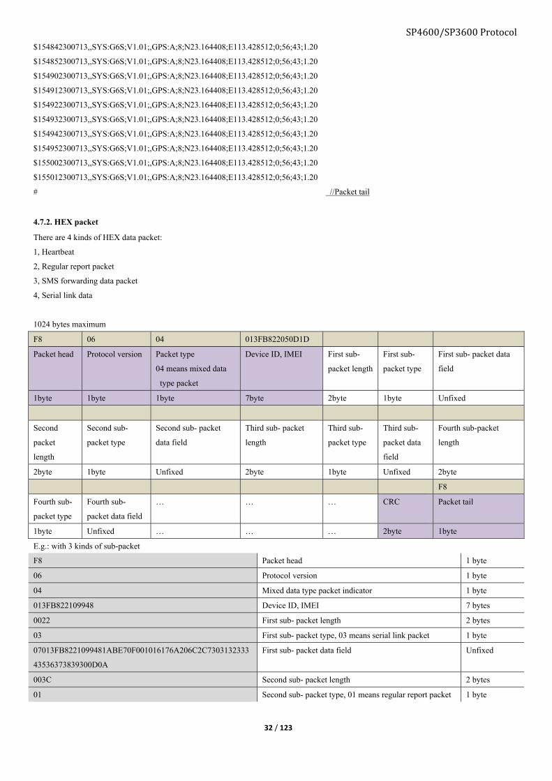
Packet batch process is major on offline data process. It will pack multiple offline packets (sub-packet) as 1 packet. Each sub-packet will use
$ as separator. Format:
packet head + first sub-packet + $second sub-packet +$...... +$last sub-packet + packet tail
1024 bytes maximum.
E.g.:
*GS06,356496042429597, //Packet head
154812300713,,SYS:G6S;V1.01;,GPS:A;8;N23.164408;E113.428512;0;56;43;1.20 //first sub-packet has not $ ahead
$154822300713,,SYS:G6S;V1.01;,GPS:A;8;N23.164408;E113.428512;0;56;43;1.20 //from second sub-packet there is $ ahead
$154832300713,,SYS:G6S;V1.01;,GPS:A;8;N23.164408;E113.428512;0;56;43;1.20
SP4600/SP3600 Protocol
32 / 123
$154842300713,,SYS:G6S;V1.01;,GPS:A;8;N23.164408;E113.428512;0;56;43;1.20
$154852300713,,SYS:G6S;V1.01;,GPS:A;8;N23.164408;E113.428512;0;56;43;1.20
$154902300713,,SYS:G6S;V1.01;,GPS:A;8;N23.164408;E113.428512;0;56;43;1.20
$154912300713,,SYS:G6S;V1.01;,GPS:A;8;N23.164408;E113.428512;0;56;43;1.20
$154922300713,,SYS:G6S;V1.01;,GPS:A;8;N23.164408;E113.428512;0;56;43;1.20
$154932300713,,SYS:G6S;V1.01;,GPS:A;8;N23.164408;E113.428512;0;56;43;1.20
$154942300713,,SYS:G6S;V1.01;,GPS:A;8;N23.164408;E113.428512;0;56;43;1.20
$154952300713,,SYS:G6S;V1.01;,GPS:A;8;N23.164408;E113.428512;0;56;43;1.20
$155002300713,,SYS:G6S;V1.01;,GPS:A;8;N23.164408;E113.428512;0;56;43;1.20
$155012300713,,SYS:G6S;V1.01;,GPS:A;8;N23.164408;E113.428512;0;56;43;1.20
# //Packet tail
4.7.2. HEX packet
There are 4 kinds of HEX data packet:
1, Heartbeat
2, Regular report packet
3, SMS forwarding data packet
4, Serial link data
1024 bytes maximum
F8 06 04 013FB822050D1D
Packet head Protocol version Packet type
04 means mixed data
type packet
Device ID, IMEI First sub-
packet length
First sub-
packet type
First sub- packet data
field
1byte 1byte 1byte 7byte 2byte 1byte Unfixed
Second
packet
length
Second sub-
packet type
Second sub- packet
data field
Third sub- packet
length
Third sub-
packet type
Third sub-
packet data
field
Fourth sub-packet
length
2byte 1byte Unfixed 2byte 1byte Unfixed 2byte
F8
Fourth sub-
packet type
Fourth sub-
packet data field
… … … CRC Packet tail
1byte Unfixed … … … 2byte 1byte
E.g.: with 3 kinds of sub-packet
F8 Packet head 1 byte
06 Protocol version 1 byte
04 Mixed data type packet indicator 1 byte
013FB822109948 Device ID, IMEI 7 bytes
0022 First sub- packet length 2 bytes
03 First sub- packet type, 03 means serial link packet 1 byte
07013FB8221099481ABE70F001016176A206C2C7303132333
43536373839300D0A
First sub- packet data field Unfixed
003C Second sub- packet length 2 bytes
01 Second sub- packet type, 01 means regular report packet 1 byte

33 / 123
1ABE70F100330E1556322E303627312E302E352D5413003F4
6016176A206C2C730000000000006009604056311860C01801
1E021003100410051
Second sub- packet data field
SP4600/SP3600 Protocol Unfixed
0022 Third sub- packet length 2 bytes
03 Third sub- packet type, 03 means serial link packet 1 byte
07013FB8221099481ABE70F301016176A206C2C7303339323
33133353431330D0A
Third sub- packet data field Unfixed
003C Fourth sub- packet length 2 bytes
01 Fourth sub- packet type, 01 means regular data packet 1 byte
1ABE70FB00330E1556322E303627312E302E352D5413003F4
6016176A206C2C730000000000006009604054F11860C01801
1E02100310041005101
Fourth sub- packet data field Unfixed
003C Fifth sub- packet length 2 bytes
01 Fifth sub- packet type, 01 means regular data packet 1 byte
1ABE710500330E1556322E303627312E302E352D5413003F4
6016176A206C2C730000000000006009604055E11860C01801
1E02100310041005101
Firth sub- packet data field Unfixed
0016 Sixth sub- packet length 2 bytes
02 Sixth sub- packet type, 03 means SMS forwarding packet 1 byte
04910D683129461465F00A30313233343536373839 Sixth sub- packet data field Unfixed
003C Seventh sub- packet length 2 bytes
01 Seventh sub- packet type, 01 means regular data packet 1 byte
1ABE710F00330E1556322E303627312E302E352D5413003F4
6016176A206C2C730000000000006009604056111860C01801
1E02100310041005101
Seventh sub- packet data field Unfixed
003C Eighth sub- packet length 2 bytes
01 Eighth sub- packet type, 01 means regular data packet 1 byte
1ABE711900330E1556322E303627312E302E352D5413003F4
6016176A206C2C730000000000006009604054F11860C01801
1E02100310041005101
Eighth sub- packet data field Unfixed
9EBF CRC 2 bytes
F8 Packet tail 1 byte
5. Packet sample
>Device packet to GPRS server, ASCII format:
■With GSM data
*GS06,356496042329318,000000000000,,SYS:G6S;V1.00;V1.0.1,GSM:5;4;460;0;2503;962C;-59#
*GS06,356496042329318,000000000000,,SYS:G6S;V1.00;V1.0.1,GSM:5;4;460;0;2503;962C;-59#
*GS06,356496042329318,000000000000,92,SYS:G6S;V1.00;V1.0.1#
■With GPS data

SP4600/SP3600 Protocol
34 / 123
*GS06,356496042329318,031427090613,,SYS:G6S;V1.00;V1.0.1,GPS:A;7;N23.164358;E113.428515;0;0;45;1.10#
*GS06,356496042329318,031417090613,,SYS:G6S;V1.00;V1.0.1,GPS:A;7;N23.164358;E113.428515;0;0;44;1.10#
>Device packet to GPRS server, HEX format:
F8060101443B33F78BE41946E33E003310034736531556312E30302556312E3031123F490161792C06C2C84000000000008B008604031C11
F40902308C1180210031009846F8
6. CommandCommand lists for different authorization, please refer APPENDIX1
6.1. Command format # Communication Chapter Operation type Format
1 Server to Device 5.1.1 TCP/UDP socket to send *GS00,UNO;+8601234567891#
SMS server *GS00,UNO;+8601234567891#
2 Serial port to Device 5.1.2 Configuration software or
serial port software UNO;+8601234567891
3 User phone to Device 5.1.3 Cell phone to send 1234,UNO;+8601234567891
6.1.1 Server to device command format
Server sends:
*GS 06 , <Command word1>;<Parameter>;<Parameter>,
<Command word2>;<Parameter>;<Parameter>
#
Command
head
Protocol
version
Separator Command field:
Command word and its parameter using “;” as separator.
Different command field using “,” as separator
Command
tail
Device replies:
*GS 06 , 358696040652862 , <Command
word>:<Parameter>;<Parameter>,<Comman
d word>:<Parameter>;<Parameter>
#
Packet
head
Protocol
version
Separator Device ID Separator Command field Packet
tail
e.g.:
Send: *GS00,UNO;13912345678#
Reply: *GS06,358696040652862,UNO:13912345678#
6.1.2 Serial port to device command format
Send Reply
<Command word>;<Parameter>;<Parameter> <Command word>:<Parameter>;<Parameter>
Command field:
Separator is “;”
Command field:
Separator between command word and parameter using “:” as
separator,

SP4600/SP3600 Protocol
35 / 123
Parameters in identical command word using “;” as separator.
e.g.:
Send: UNO;13912345678
Reply: UNO:13912345678
6.1.3 User phone to device command format
1234 , <Command word>;<Parameter>;<Parameter>
Password Separator Command field
Command field
Command word and its parameter using “;” as separator.
Different command field using “,” as separator
Send: 1234,UPW;1234
Reply: G6S V1.00
UPW:1234
EXT_PWR=11.94V
BAT=3.90V
#3
6.1.4 Command combination
■Multiple commands to send in one message, length 256 maximum.
Server to device
Between different command using “,” as separator
e.g.:
Send: *GS00,UNO;13912345678,UPW;1234#
Reply: *GS06,0123456789,UNO:13912345678,UPW:1234#
User phone to device
Between different commands using “,” as separator
e.g.:
Send:1234,UNO;13912345678,UPW;4567
Reply: G6S V1.00
UNO:13912345678
UPW:1234
EXT_PWR=11.94V
BAT=3.90V
#3
Computer to device
Between different command using “,” as separator
Send:
UNO;13912345678,UPW;1234
Reply:
UNO:13912345678,UPW:1234

SP4600/SP3600 Protocol
36 / 123
6.2. OEM command Format:
Send : *GS00,UCM;FFFF#
Reply: *GS06,358696040652862,UCM:FFFF#
6.2.1 Reset to factory default (DFP)
Command word Format Reply
DFP DFP DFP
Explanation Device configuration will be reset
6.2.2 Set OEM password (OPW)
Command word Format Reply
OPW OPW;0123456789 OPW:0123456789
OPW OPW:0123456789
Explanation OPW;<PASSWORD>
This password is for the accessibility of configuration software on computer.
Length is 10 digits fixed.
Default password: 0123456789
6.2.3 Administrator command mask (ACM)
Command word Format Reply
ACM ACM;1F8 ACM:1F8
ACM ACM:1F8
Explanation ACM;<Mask>
Enable commands in OEM command list for administrator, except commands DFP/OPW/ACM.
<Mask>:HEX, range is “0 to FFFFFFFFFFFFFFFF”
“0”: disable this command for administrator
”1”: enable this command for administrator
Refer APPENDIX1 for OEM command list.
Factory default: ACM:3FFFFFFFF8
6.2.4 User command mask (UCM)
Command word Format Reply
UCM UCM;1FFFFFFFFFF UCM:1FFFFFFFFFF

SP4600/SP3600 Protocol
37 / 123
UCM UCM: 1FFFFFFFFF
Explanation UCM;<Mask>
Enable commands in user command list for user.
<Mask>:HEX, range is “0 to FFFFFFFFFFFFFFFF”
“0”: disable this command for user
”1”: enable this command for user
Refer APPENDIX2 for user command list.
Factory default: UCM:1FFFFFCFF5F
6.2.5 OTA firmware upgrade file server (OAS)
Command word Format Reply
OAS OAS;update.skypatrol.com;80 OAS:update.skypatrol.com;80
OAS OAS:update.skypatrol.com;80
Explanation OAS;<IP>;<PORT>
Set OTA server IP and port, 63 characters maximum.
<IP/Domain>: IP of OTA server
<Port>: Port of OTA server
Factory default: OAS:update.skypatrol.com;80
6.2.6 OTA firmware file path (OAP)
Command word Format Reply
OAP OAP;/skypatrol/G6S/V105/Release/G6S.txt OAP:/skypatrol/G6S/V105/Release/G6S.txt
OAP OAP:/skypatrol/G6S/V105/Release/G6S.txt
Explanation OAP;<File path>
<File path>:
64bytes maximum, OTA file path on OTA server
Factory default: OAP:/skypatrol/G6S/Release/G6S.txt
6.2.7 APN information list (APL)
Command word Format Reply
APL APL;46000;cmnet;user;pw APL:46000;cmnet;user;pw

SP4600/SP3600 Protocol
38 / 123
APL;46000 APL:46000;cmnet;user;pw
Explanation Device is able to save APN list on device, when SIM card inserted to automatically fulfill APN information.
There is 4K byte memory is used for APN list.
Device will keep the newest APN in memory.
APL;<MCC+MNC>;<APN>;<user name>;<pw>
<MCC+MNC>: 3 digits for country code, 2 or 3 digits for carrier code
<APN>: APN name, maximum 64 bytes
<user name>: User name for APN
<pw>: password for APN
Factory default: Chinese APN
6.2.8 Heartbeat packet (HBI)
Command word Format Reply
HBI HBI;50 HBI:50
HBI HBI:50
Explanation Function: Set up the heartbeat packet uploading time interval of TCP/UDP sever, keep the sever and device connected..
HBI;<Interval>
<Interval>: 0:Close the heartbeat packet uploading;
Range is “1 to 255”, unit is minute.
Factory default:HBI;20
6.2.9 Map hyper link (URL)
Command word Format Reply
URL Static link:
URL0;http://maps.google.com/maps?q=%n(,%e&t=m
&z=16
URL0:http://maps.google.com/staticmap?zoom=14&size=300x
300&markers =%n(;%e&sensor=false
Dynamic link:
URL0;http://maps.google.com/maps?q=%n(,%e&t=m
&z=16
URL0;http://maps.google.com/maps?q=%n(,%e&t=m&z=16
Explanation This command is to set map link in SMS to user
URL[ID];<Link>
URL0 is to set GPS hyper map link.
URL1 is to set GSM hyper map link.

SP4600/SP3600 Protocol
39 / 123
URL0 is prior when GPS is fixed.
<Link>: Maximum is 126bytes, “)” is used for data conversion.
Valid parameter that following “%”, case sensitive
“y”: year
“m”: month
“H”: hour
“M”: minute
“S”: second
“n”: north
“e”: east
“a”: valid flag
“s”: speed
“r”: heading
“C”: MCC
“N”: MNC
“A”: LAC
“D”: CID
Factory default:URL0;http://maps.google.com/maps?q=%n,%e&t=m&z=16
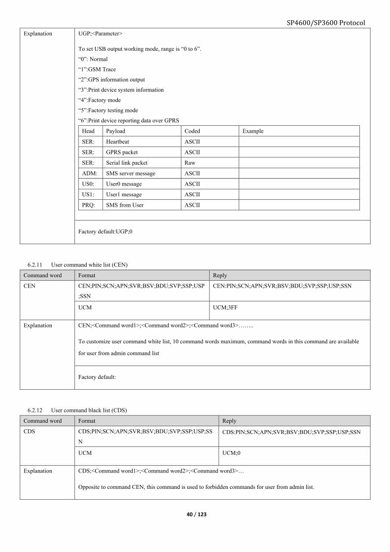
6.2.10 USB port output mode (UGP)
Command word Format Reply
UGP UGP;3 UGP:3
UGP UGP:3
SP4600/SP3600 Protocol
40 / 123
Explanation UGP;<Parameter>
To set USB output working mode, range is “0 to 6”.
“0”: Normal
“1”:GSM Trace
“2”:GPS information output
“3”:Print device system information
“4”:Factory mode
“5”:Factory testing mode
“6”:Print device reporting data over GPRS
Head Payload Coded Example
SER: Heartbeat ASCII
SER: GPRS packet ASCII
SER: Serial link packet Raw
ADM: SMS server message ASCII
US0: User0 message ASCII
US1: User1 message ASCII
PRQ: SMS from User ASCII
Factory default:UGP;0
6.2.11 User command white list (CEN)
Command word Format Reply
CEN CEN;PIN;SCN;APN;SVR;BSV;BDU;SVP;SSP;USP
;SSN
CEN:PIN;SCN;APN;SVR;BSV;BDU;SVP;SSP;USP;SSN
UCM UCM;3FF
Explanation CEN;<Command word1>;<Command word2>;<Command word3>……..
To customize user command white list, 10 command words maximum, command words in this command are available
for user from admin command list
Factory default:
6.2.12 User command black list (CDS)
Command word Format Reply
CDS CDS;PIN;SCN;APN;SVR;BSV;BDU;SVP;SSP;USP;SS
N CDS:PIN;SCN;APN;SVR;BSV;BDU;SVP;SSP;USP;SSN
UCM UCM;0
Explanation CDS;<Command word1>;<Command word2>;<Command word3>…
Opposite to command CEN, this command is used to forbidden commands for user from admin list.

SP4600/SP3600 Protocol
41 / 123
CDS;PIN;SCN;APN;SVR;BSV;BDU;SVP;SSP;USP;SSN
CDS:PIN;SCN;APN;SVR;BSV;BDU;SVP;SSP;USP;SSN
UCM
UCM:0
Factory default:
6.2.13 Sub-data type mask (SDM)
Command word Format Reply
SDM SDM1;FFFF SDM1:7F
SDM1 SDM1:7F

SP4600/SP3600 Protocol
42 / 123
Explanation To set Sub-data type mask.
Format:
SDM[Main data identifier]; <Sub-data type mask>
<Main data identifier>: range is “0 to 15”, refer command AMD “Main data type list”.
<Sub-data mask>:
HEX, range is “0000 to FFFF”.
“0” means not report.
“1” means report.
<1>SYS: System data mask (SDM0)
Bit Sub-data type 0 1 Length, ASCII Length, HEX
0 Device name Not report Report <=15bytes <=15bytes
1 Firmware version Not report Report <=8bytes <=8bytes
2 Hardware
version Not report Report
<=8bytes <=8bytes
<2>GPS: GPS data mask (SDM1)
Bit Sub-data type 0 1 Length, ASCII Length, HEX
0 Fix flag
Not report Report =1bytes =1byte
Valid satellite number <=2bytes
1 Latitude
Not report Report 10bytes =8bytes
Longitude 11bytes
2 Speed Not report Report <=3bytes =2bytes
3 Azimuth Not report Report <=3bytes =2bytes
4 Altitude Not report Report <=5 =2bytes
5 HDOP Not report Report <=5 =2bytes
6 VDOP Not report Report <=5 =2bytes
7 Reserved
<3>GSM: GSM data (SDM2)
Bit Sub-data type 0 1 Length, ASCII Length, HEX
0 Register status
Not report Report =1bytes =1bytes
Signal strength =1bytes
1 First station Not report Report <=25bytes =8bytes
2 Second station Not report Report <=25bytes =8bytes
3 Third station Not report Report <=25bytes =8bytes
4 Fourth station Not report Report <=25bytes =8bytes
5 Fifth station Not report Report <=25bytes =8bytes
6 Sixth station Not report Report <=25bytes =8bytes
7 Seventh station Not report Report <=25bytes =8bytes
<4>COT: COT data (SDM3)
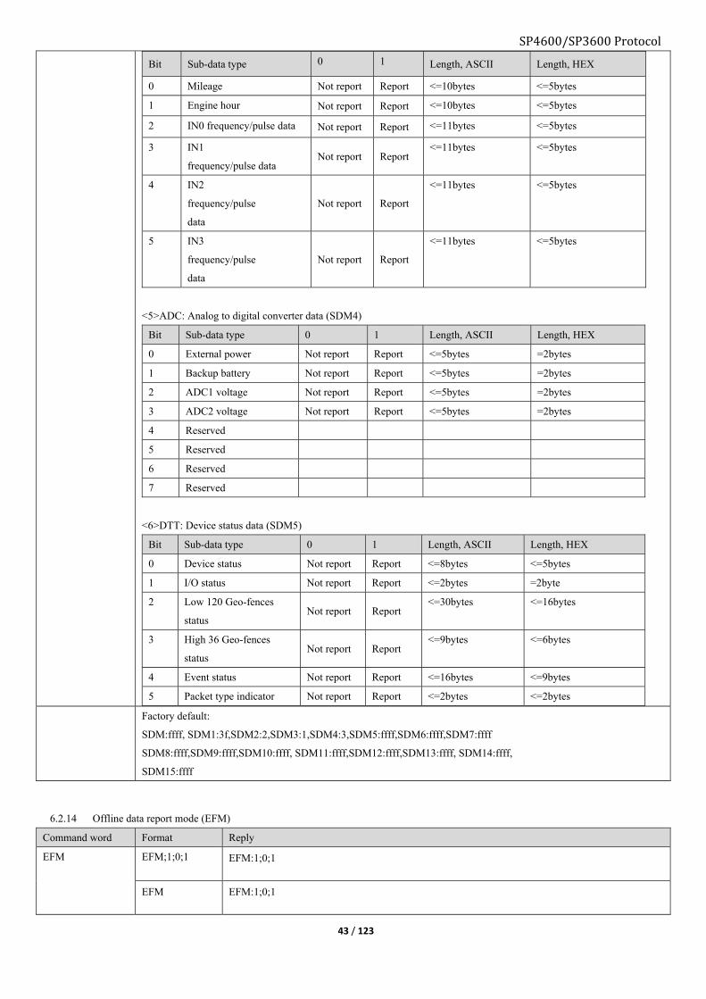
43 / 123
Bit Sub-data type 0 1 Length, ASCII Length, HEX
0 Mileage Not report Report <=10bytes <=5bytes
1 Engine hour Not report Report <=10bytes <=5bytes
2 IN0 frequency/pulse data Not report Report <=11bytes <=5bytes
3 IN1
frequency/pulse data Not report Report
<=11bytes <=5bytes
4 IN2
frequency/pulse
data
Not report Report
<=11bytes <=5bytes
5 IN3
frequency/pulse
data
Not report Report
<=11bytes <=5bytes
<5>ADC: Analog to digital converter data (SDM4)
Bit Sub-data type 0 1 Length, ASCII Length, HEX
0 External power Not report Report <=5bytes =2bytes
1 Backup battery Not report Report <=5bytes =2bytes
2 ADC1 voltage Not report Report <=5bytes =2bytes
3 ADC2 voltage Not report Report <=5bytes =2bytes
4 Reserved
5 Reserved
6 Reserved
7 Reserved
<6>DTT: Device status data (SDM5)
Bit Sub-data type 0 1 Length, ASCII Length, HEX
0 Device status Not report Report <=8bytes <=5bytes
1 I/O status Not report Report <=2bytes =2byte
2 Low 120 Geo-fences
status Not report Report
<=30bytes <=16bytes
3 High 36 Geo-fences
status Not report Report
<=9bytes <=6bytes
4 Event status Not report Report <=16bytes <=9bytes
5 Packet type indicator Not report Report <=2bytes <=2bytes
Factory default:
SDM:ffff, SDM1:3f,SDM2:2,SDM3:1,SDM4:3,SDM5:ffff,SDM6:ffff,SDM7:ffff
SDM8:ffff,SDM9:ffff,SDM10:ffff, SDM11:ffff,SDM12:ffff,SDM13:ffff, SDM14:ffff,
SDM15:ffff
6.2.14 Offline data report mode (EFM)
Command word Format Reply
EFM EFM;1;0;1 EFM:1;0;1
EFM EFM:1;0;1
SP4600/SP3600 Protocol

SP4600/SP3600 Protocol
44 / 123
Explanation EFM;<Mode>;<Priority>;<Erase>
<Mode>
0: Disable offline (GPRS) data saving feature
1: Enable offline (GPRS) data saving feature, If GPRS recovers device will send offline data to server.
<Priority>
0: Real-time data prior, when GPRS recovers send the real time data first.
1: Offline data prior, when GPRS recovers send the offline data first.
<Erase>
1: Erase offline data from flash storage. (Need to include former 2 parameters when executing)
0: Do not offline data from flash storage. (Changing former 2 parameters without erasing)
EFM:1;1
6.2.15 Sub-event mask (ESM)
Command word Format Reply
ESM ESM3;FF;FF;FF;FF ESM3: FF;FF;FF;FF
ESM ESM3:FF;FF;FF;FF

SP4600/SP3600 Protocol
45 / 123
Explanation ESM[Main event ID];<Sub-event mask>;<Sub-event status0 mask>;
<Sub-event status1 mask>;<Clear type>
[Main event ID]: Range is “0 to 7”, one main event type including 8 sub events.
<Sub-event mask>:
HEX, range is “0 to FF”
"0”: Disable this sub-event
“1”: Enable this sub-event
<Sub-event status0 mask>:
HEX, range is “0 to FF”
“0”: Disable sub-event status0 to trigger
“1”: Enable sub-event status0 to trigger
<Sub-event status1 mask>:
HEX, range is “0 to FF”
“0”: Disable sub-event status1 to trigger
“1”: Enable sub-event status1 to trigger
<Clear type>:
HEX, range is “0 to FF”
“0”: Manually
“1”: Automatically
Note: Definition of Main event, sub-event, status0/1 please refer chapter9 “Event list”
Factory default:
ESM:0;0;0;ff
ESM1:0;0;0;ff
ESM2:0;0;0;ff
ESM3:10;10;10;ff
ESM4:0;0;0;ff
ESM5:0;0;0;ff
ESM6:0;0;0;ff
ESM7:0;0;0;ff
6.2.16 Device reaction for the triggered event (EUP)
Command word Format Reply
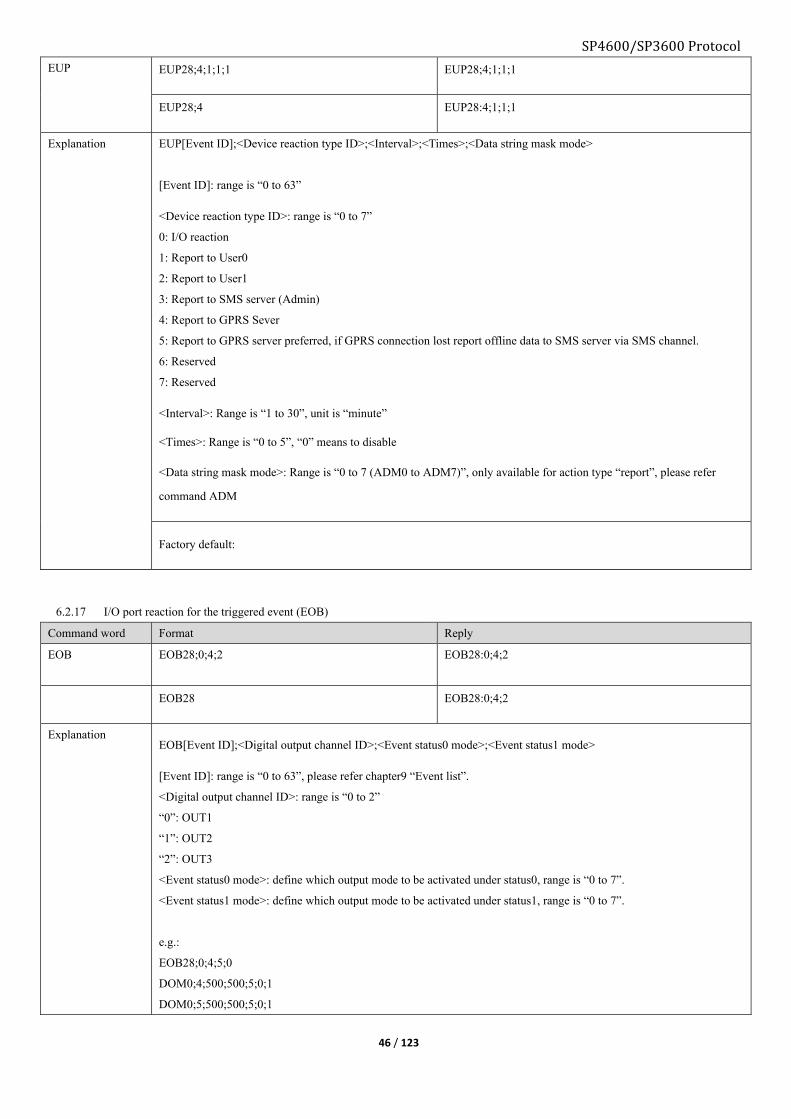
SP4600/SP3600 Protocol
46 / 123
EUP EUP28;4;1;1;1 EUP28;4;1;1;1
EUP28;4 EUP28:4;1;1;1
Explanation EUP[Event ID];<Device reaction type ID>;<Interval>;<Times>;<Data string mask mode>
[Event ID]: range is “0 to 63”
<Device reaction type ID>: range is “0 to 7”
0: I/O reaction
1: Report to User0
2: Report to User1
3: Report to SMS server (Admin)
4: Report to GPRS Sever
5: Report to GPRS server preferred, if GPRS connection lost report offline data to SMS server via SMS channel.
6: Reserved
7: Reserved
<Interval>: Range is “1 to 30”, unit is “minute”
<Times>: Range is “0 to 5”, “0” means to disable
<Data string mask mode>: Range is “0 to 7 (ADM0 to ADM7)”, only available for action type “report”, please refer
command ADM
Factory default:
6.2.17 I/O port reaction for the triggered event (EOB)
Command word Format Reply
EOB EOB28;0;4;2 EOB28:0;4;2
EOB28 EOB28:0;4;2
Explanation EOB[Event ID];<Digital output channel ID>;<Event status0 mode>;<Event status1 mode>
[Event ID]: range is “0 to 63”, please refer chapter9 “Event list”.
<Digital output channel ID>: range is “0 to 2”
“0”: OUT1
“1”: OUT2
“2”: OUT3
<Event status0 mode>: define which output mode to be activated under status0, range is “0 to 7”.
<Event status1 mode>: define which output mode to be activated under status1, range is “0 to 7”.
e.g.:
EOB28;0;4;5;0
DOM0;4;500;500;5;0;1
DOM0;5;500;500;5;0;1
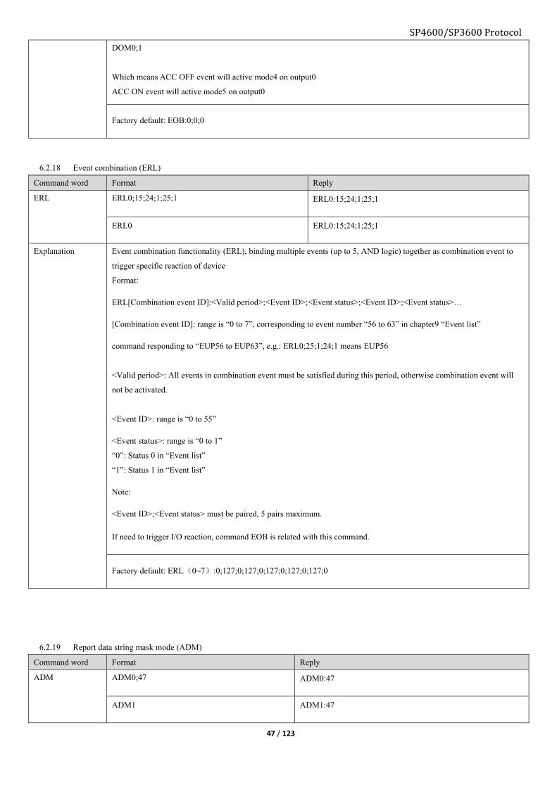
SP4600/SP3600 Protocol
47 / 123
DOM0;1
Which means ACC OFF event will active mode4 on output0
ACC ON event will active mode5 on output0
Factory default: EOB:0;0;0
6.2.18 Event combination (ERL)
Command word Format Reply
ERL ERL0;15;24;1;25;1 ERL0:15;24;1;25;1
ERL0 ERL0:15;24;1;25;1
Explanation Event combination functionality (ERL), binding multiple events (up to 5, AND logic) together as combination event to
trigger specific reaction of device
Format:
ERL[Combination event ID]:<Valid period>;<Event ID>;<Event status>;<Event ID>;<Event status>…
[Combination event ID]: range is “0 to 7”, corresponding to event number “56 to 63” in chapter9 “Event list”
command responding to “EUP56 to EUP63”, e.g.: ERL0;25;1;24;1 means EUP56
<Valid period>: All events in combination event must be satisfied during this period, otherwise combination event will
not be activated.
<Event ID>: range is “0 to 55”
<Event status>: range is “0 to 1”
“0”: Status 0 in “Event list”
“1”: Status 1 in “Event list”
Note:
<Event ID>;<Event status> must be paired, 5 pairs maximum.
If need to trigger I/O reaction, command EOB is related with this command.
Factory default: ERL(0~7):0;127;0;127;0;127;0;127;0;127;0
6.2.19 Report data string mask mode (ADM)
Command word Format Reply
ADM ADM0;47 ADM0:47
ADM1 ADM1:47
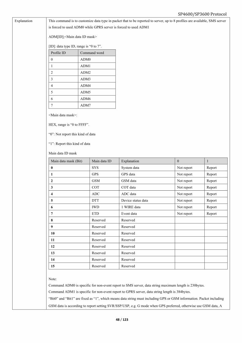
SP4600/SP3600 Protocol
48 / 123
Explanation This command is to customize data type in packet that to be reported to server, up to 8 profiles are available, SMS server
is forced to used ADM0 while GPRS server is forced to used ADM1
ADM[ID];<Main data ID mask>
[ID]: data type ID, range is “0 to 7”.
Profile ID Command word
0 ADM0
1 ADM1
2 ADM2
3 ADM3
4 ADM4
5 ADM5
6 ADM6
7 ADM7
<Main data mask>:
HEX, range is “0 to FFFF”.
“0”: Not report this kind of data
“1”: Report this kind of data
Main data ID mask
Main data mask (Bit) Main data ID Explanation 0 1
0 SYS System data Not report Report
1 GPS GPS data Not report Report
2 GSM GSM data Not report Report
3 COT COT data Not report Report
4 ADC ADC data Not report Report
5 DTT Device status data Not report Report
6 IWD 1 WIRE data Not report Report
7 ETD Event data Not report Report
8 Reserved Reserved
9 Reserved Reserved
10 Reserved Reserved
11 Reserved Reserved
12 Reserved Reserved
13 Reserved Reserved
14 Reserved Reserved
15 Reserved Reserved
Note:
Command ADM0 is specific for non-event report to SMS server, data string maximum length is 230bytes.
Command ADM1 is specific for non-event report to GPRS server, data string length is 384bytes.
“Bit0” and “Bit1” are fixed as “1”, which means data string must including GPS or GSM information. Packet including
GSM data is according to report setting SVR/SSP/USP, e.g. G mode when GPS preferred, otherwise use GSM data, A

SP4600/SP3600 Protocol
49 / 123
mode GPS and GSM both will be reported to server.
Factory default:
ADM0:47
ADM1:47
ADM2:47
ADM3:47
ADM4:47
ADM5:47
ADM6:47
ADM7:47
6.2.20 Digital output configuration (DOM)
Command word Format Reply
DOM DOM0;2;0 DOM0:2;0
DOM0;2 DOM0:2;0

SP4600/SP3600 Protocol
50 / 123
Explanation DOM[ID];<Mode>;<Parameter1>;<Parameter2>;<Parameter3>;<Parameter4>;<Parameter5>
[ID]:DO output channel ID, range is “0 to 2”
0: OUT1
1: OUT2
2: OUT3
<Mode>: Range is “0 to 7” (Mode “0”/Mode “1” have no parameter)
<Parameter1>,<Parameter2>,<Parameter3>,<Parameter4>,<Parameter5>:
To configure digital output channel, number of parameters varies with different mode.
Mode “0”:
Output low level.
Mode “1”:
Output high level.
Mode “2”:
Output rising edge.
<Parameter1>: Duration time, unit is “ms”
Mode “3”:
Output failing edge.
<Parameter2>: Duration time, unit is “ms”
Mode “4”:
Output square wave. unit is “ms”
<Parameter1>: High level duration
<Parameter2>: Low level duration
<Parameter3>: Output time, “0” means continuous output

SP4600/SP3600 Protocol
51 / 123
<Parameter4>: Start level, “0” means low level, “1” means high level
<Parameter5>: End level, “0” means low level, “1” means high level
Mode “5”:
Output square wave. unit is “ms”
Parameters the same as Mode “4”.
Mode “6”:
Output square wave. unit is “ms”
Parameters the same as Mode “4”.
Mode “7”:
Output square wave. unit is “ms”
Parameters the same as Mode “4”.
Parameter1 and parameter2 is from “0 to 99999999”, parameter3 is “0 to 65535”.
Factory default:
DOM0:2;0
DOM0:3;0
DOM0:4;0;0;0;0;0
DOM0:5;0;0;0;0;0
DOM0:6;0;0;0;0;0
DOM0:7;0;0;0;0;0
6.2.21 Set AD PIN working mode (AIM)
Command word Format Reply
AIM AIM;0;0 AIM:0;0
AIM AIM:0;0
Explanation AIM;<Mode1>;<Mode2>
<Mode1>: AD1/IN3
<Mode2>: AD2/IN4
“0”: Analog input
“1”: Digital input

SP4600/SP3600 Protocol
52 / 123
Note:
If AD1/IN3 set as digital input, it has another identifier “IN3”.
If AD2/IN4 set as digital input, it has another identifier “IN4”.
Default both set as analog, AIM:0;0
6.2.22 Digital input configuration (DIM)
Command word Format Reply
DIM DIM0;0 DIM0:0
DIM DIM0:0
Explanation DIM[ID];<Mode>;<Parameter1>;<Parameter2>;<Parameter3>
[ID]: Digital input channel ID, range is “0 to 3”
“0”: IN1, digital input channel1
“1”: IN2, digital input channel2
“2”: IN3, digital input channel3, valid only when AD1/IN3 set as digital.
“3”: IN4, digital input channel4, valid only when AD2/IN4 set as digital.
<Mode>: Range is “0 to 7”.
<Parameter1>,<Parameter2>,<Parameter3>:
To configure digital input channel, number of parameters varies with different mode.
Mode “0”:
Voltage level sampling, level changes will trigger event. (Not parameter)
Mode “1”:
Frequency counter, pulse frequency sampling, if input frequency outside the range will trigger event. (2 parameters)
<Parameter1>: Frequency lower limit
<Parameter2>: Frequency upper limit
Mode “2”:
Pulse counter, counting number of input pulse. (3 parameters)
<Parameter1>: Set initial value of counter
<Parameter2>: Set counter value threshold, surpass this value will trigger event.
<Paramete3>: Reset counter value to zero when reach threshold, “0” is not reset, “1” is reset.
Mode “3”:
Low level. (1 parameter)
<Parameter1>:
Set low level duration time, unit is “ms”, surpass this value will trigger event.
Mode “4”:

SP4600/SP3600 Protocol
53 / 123
High level. (1 parameter)
<Parameter1>:
Set low level duration time, unit is “ms”, surpass this value will trigger event.
Mode “5”:
Rising edge (3 parameters)
<Parameter1>: Set initial value of counter
<Parameter2>: Set counter value threshold, surpass this value will trigger event.
<Paramete3>: Reset counter value to zero when reach threshold, “0” is not reset, “1” is reset.
Mode “6”:
Failing edge (3 parameters)
<Parameter1>: Set initial value of counter
<Parameter2>: Set counter value threshold, surpass this value will trigger event.
<Paramete3>: Reset counter value to zero when reach threshold, “0” is not reset, “1” is reset.
Mode “7”:
Edge (3 parameters).
<Parameter1>: Set initial value of counter
<Parameter2>: Set counter value threshold, surpass this value will trigger event.
<Paramete3>: Reset counter value to zero when reach threshold, “0” is not reset, “1” is reset.
e.g.:
DIM1;0
It means IN2 mode set as 0, if input level changes will trigger event.
DIM1;1;500;1000
It means IN2 mode set as 1, if input frequency outside “500 to 1000” will trigger event.
Note: Level mode is recommended
Default: DIM:0
6.2.23 Analog input configuration (ADS)
Command word Format Reply
ADS ADS0;1;8 ADS0:1;8
ADS ADS0:1;8
Explanation ADS[ID];<Sample interval>;<Sample times>
[ID]: 0 or 1;
“0”: AD1/IN3, valid only when set as analog.
“1”: AD2/IN4, valid only when set as analog.

SP4600/SP3600 Protocol
54 / 123
<Sample interval>:AD sampling interval, unit is “second”, range is “0 to 65535”
<Sample times>: Times of each AD sampling, output is average value of sample times, range is “0 to 256”
Factory default: ADS0;1;8,ADS1;1;8
6.2.24 Set serial port communication (EPS)
Command word Format Reply
EPS EPS;4;0;1;0 EPS:4;0;1;0
EPS EPS:4;0;1;0
Explanation EPS;<Baud rate index>;<Data bit>;<Stop bit>;<Verify bit>
Baud rate index Data bit Stop bit Verify bit
Index Rate 0:8 bit mode 0:0.5 stop bit 0: Not verify
0 600 1:9 bit mode 1:1 stop bit 1: Even verify
1 1200 2:1.5 stop bit 2: Odd verify
2 2400 3:2 stop bit
3 4800
4 9600
5 14400
6 19200
7 38400
8 56000
9 57600
10 115200
Factory default: EPS:4;0;1;0
6.2.25 Serial port mode configuration (EPM)
Command word Format Reply
EPM EPM;0
EPM;2;100
EPM:0
EPM;2;100
EPM EPM;2;100
Explanation EPM;<Mode>;<Interval>
<Mode>: range is “0 to 6”.
“0”: Disable serial port outputs
“1”: Transparent data mode
“2”: Transparent data mode with configurable packet interval
“3”: GARMIN protocol mode
“4”: GPS data input, under this mode device will use external GPS input as source instead of its original.
“5”: MDT mode, this mode must be selected when serial link connects with MDT

SP4600/SP3600 Protocol
55 / 123
“6”: For idata protocol based peripheral device.
<Interval>: Only valid when <Mode> is “2”, unit is ms, range is “5 to 65535”.
Default: EPM;1
6.2.26 Harsh behavior configuration (BMS)
Command word Format Reply
BMS BMS;2;10;45;35;40;30 BMS:2;10;45;35;40;30
BMS BMS:2;10;45;35;40;30
Explanation BMS;<moving_para>;<harsh_brake_para>;<harsh_accelerate_para>;<harsh_corner_left_para>;<harsh_corner_right_par
a>
<moving_para>:
Device motion status acceleration magnitude threshold, range is “1 to 200”, unit is 0.01g.
<harsh_brake_para>:
Device harsh brake acceleration magnitude threshold, range is “1 to 200”, unit is 0.01g.
<harsh_accelerate_para>:
Device harsh accelerates acceleration magnitude threshold, range is “1 to 200”, unit is 0.01g.
<harsh_corner_left_para>:
Device harsh left cornering acceleration magnitude threshold, range is “1 to 200”, unit is 0.01g.
<harsh_corner_right_para>
Device harsh right cornering acceleration magnitude threshold, range is “1 to 200”, unit is 0.01g.
Default: BMS:2;10;45;35;40;30
6.2.27 Accident detection configuration (AMS)
Command word Format Reply
AMS AMS;150;90 AMS:150;90
AMS AMS:150;90

SP4600/SP3600 Protocol
56 / 123
Explanation AMS;<crash_para>;<trun_over_para>
<crash_para>:
Crash (collision) acceleration magnitude threshold, range is “1 to 200”, unit is 0.01g.
Note: Sensor itself will judge front or rear collision, side collision will be considered as rear.
<trun_over_para>:
Turn over acceleration magnitude threshold, range is “1 to 200”, unit is 0.01g.
Default: AMS:150;90
6.2.28 Geo-fence mask (UFM)
Command word Format Reply
UFM UFM;FFFFFFFFFFFFFFFFFFFFFFFFFFFFFFFFFFFFFFF UFM:FFFFFFFFFFFFFFFFFFFFFFFFFFFFFFFFFFFFFFF
UFM UFM:FFFFFFFFFFFFFFFFFFFFFFFFFFFFFFFFFFFFFFF
Explanation UFM;<use_mask>
<use_mask>:
User Geo-fence mask, 156 Geo-fences in total (0 - 155), Bit0 – Bit27, Bit28 – Bit159.
“0”: Disable this geo fence for user
“1”: Enable this geo fence for user
Default: UFM:1
6.2.29 A-GPS configuration (AGS)
Command word Format Reply
AGS AGS;[email protected];Moouaq AGS:[email protected];Moouaq
AGS AGS:[email protected];Moouaq
Explanation This command is to set username and password to connect with AGPS server.
<Username>:48 characters maximum.
<Password>:12 characters maximum
Default: AGS;[email protected];Moouaq
6.2.30 Set AD1/IN3 voltage level (AIR)
Command word Format Reply
AIR AIR;0 AIR:0
AIR AIR:0

SP4600/SP3600 Protocol
57 / 123
Explanation AIR;<Mode>
“0”: Define input as “0 to 12V”
“1”: Define input as “0 to 32V”
Default: AIR:0
6.2.31 Serial port data string configuration (PKI)
Command word Format Reply
PKI PKI;1;1;1 PKI:1;1;1
PKI PKI:1;1;1
Explanation This command is to data type carrying in serial port packet.
PKI;<Device ID>;<Time flag>;<Position information>
<Device ID>: ”0” not carrying device ID, “1” carrying device ID
<Time flag>: ”0” not carrying time flag, “1” carrying time flag
<Position information>: ”0” not carrying position, “1” carrying position
Default: PKI:1;1;1
6.2.32 Power saving mode configuration (PSS)
Command word Format Reply
PSS PSS0;0 PSS0:0
PSS0 PSS0:0
Explanation PSS<Module>;<Toggle>;<Para1>;<Para2>;<Para3>
<Module>
Value Explanation
0 GSM module
1 GPS module
2 2D accelerate sensor
<Toggle>:
“0” disable power saving
“1” enable power saving
■GSM module:
PSS0;1;<para1>;<para2>;<para3>
<para1>: Unregistered duration time threshold, unit is minute, range is “1 to 255”
<para2>: No data transmission duration time threshold, unit is minute, range is “1 to 255”
<para3>: Awake interval, unit is minute, range is “1 to 255”
■GPS module
PSS1;1;<para1>;<para2>
<para1>: GPS un-fixed duration time threshold, unit is minute, range is “1 to 255”

SP4600/SP3600 Protocol
58 / 123
<para2>: Awake interval, unit is minute, range is “1 to 65535”
■2D accelerate sensor module
PSS2;<Toggle>
If GSM unregistered duration surpasses threshold time or no data transmission duration surpasses threshold time, power
saving will be activated. Under power saving if device detects data transmit request and able to establish socket
connection before, it will wake up instantly; otherwise device wakes up according to awaken interval.
If GPS un-fixed duration surpasses threshold time or under parking status, power saving will be activated.
Before activation if GPS un-fixed, device will wakes up according to awake interval, otherwise it will wake up when
vehicle leaves parking status.
If GSM and GPS both under power saving, MCU will go to power saving as well.
Default:
PSS0;0
PSS1;1;5;10
PSS2;0
6.2.33 Toggle GSM/GPS module power saving (GPO)
Command word Format Reply
GPO GPO;1;1 GPO:1;1
GPO GPO:1;1
Explanation This command is to control module working status.
Format:
GPO;<Toggle GSM>;<Toggle GPS>
<Toggle GSM>:
0: disable GSM power saving
1: enable GSM power saving
<Toggle GPS>:
0: disable GPS power saving
1: enable GPS power saving
Default: GPO;1;1
6.2.34 Load command list profile from computer to device (YSF)
Command word Format Reply
YSF YSF;1 YSF:1

SP4600/SP3600 Protocol
59 / 123
Explanation Download command list profile (.txt) from computer to device, complying Ymodem protocol
Format:
YSF;<ID>
<ID>: range is “0 to 5”
0: OEM default
1 to 5: for user customized
Note: Profile file size must be less than 4095bytes, each command in profile must end with <LF><LR>, file name must
be less than 31 characters.
Default: Null
6.2.35 Save command list profile from device to computer (YGF)
Command word Format Reply
YGF YGF;1 YGF:1
Explanation Download command list profile from device to computer, complying Ymodem protocol
Format: YGF;<ID>
<ID>: range is “0 to 5”
0: OEM default
1 to 5: for user customized
Default: Null
6.2.36 Load device existing command list profile (YCF)
Command word Format Reply
YCF YCF;1 YCF:1
Explanation Execute existing command list profile form device
Format:
YCF;<ID>
<ID>: range is “0 to 5”
0: OEM default
1 to 5: for user customized
Default: Null
6.2.37 Switch configuration profile on condition (FRL)
Command word Format Reply
FRL FRL1;7;7 FRL1:7;7
FRL1 FRL1:7;7

SP4600/SP3600 Protocol
60 / 123
Explanation This command is to set when all selected conditions are satisfied, device will automatically switch among configuration
profiles.
Format: FRL[ID];<condition mask>;<status mask>
<ID>: range is 0 to 5, “0” is system reserved.
<condition mask>: range is “0x00 to 0xFFFF”
0: condition does not need to be satisfied.
1: condition need to be satisfied
<status mask>: range is “0x00 to 0xFFFF”
0: status0 need to be satisfied.
1: status1 need to be satisfied.
Condition and their status0/status1:
Byte Bit Condition Status0 Status1
1 Bit0 bExtPwr External power Normal Abnormal
Bit1 bInterBat Backup battery Normal Abnormal
Bit2 bRoaming Domestic roaming Quit roaming Roaming
Bit3 bInterRoam International roaming Quit roaming Roaming
Bit4 bGeoFence Geo-fence Normal In or Out
Bit5 bStop Parking Parking Quit parking
Bit6 bWorkStatus Private hour Inactive Active
Bit7 bAccOn ACC ON to OFF OFF to ON
2 Bit8 bIn1 Digital input IN1 High level or Null Low level
Bit9 bIn2 Digital input IN2 High level or Null Low level
Bit10 bIn3 Digital input 3 Low level High level
Bit11
Bit12
Bit13
Bit14
Bit15
Note: Selected conditions must be satisfied at the same time to trigger switching between command list profile.
Default: Null
6.2.38 Output port speed condition (DOP)
Command word Format Reply
DOP DOP;40;40;40 DOP:40;40;40
DOP DOP:40;40;40

SP4600/SP3600 Protocol
61 / 123
Explanation GPS speed must be smaller than preset speed to activate output, if GPS speed invalid, output will be active immediately.
Format
DOP;<Out1>;<Out2>;<Out3>
Explanation
<Out1>: OUT1 activate speed threshold.
<Out2>: OUT2 activate speed threshold.
<Out3>: OUT3 activate speed threshold.
Default: DOP;40;40;40
6.2.39 GSM Anti-Jamming configuration (JMP)
Command word Format Reply
JMP JMP;30;10;120 JMP:30;10;120
JMP JMP:30;10;120
Explanation This command is to set GSM jamming condition.
Format:
JMP;<RSSI threshold>;<Enter jamming Counter>;<Leave jamming Counter>
<RSSI threshold>: GSM signal strength threshold to decide being jammed or not, range “20 to 50”.
<Enter jamming counter>: device will compare current RSSI with <RSSI threshold>, if bigger than <RSSI threshold>,
counter will accumulate 1, otherwise not. When the counter value over <enter jamming counter>, device considers itself
being jammed, range “5 to 600”.
<Leave jamming counter>: device will compare current RSSI with <RSSI threshold>, if small than <RSSI threshold>,
counter will accumulate 1, otherwise not. When the counter value over <Leave jamming counter>, device considers itself
not being jammed, range “30 to 250”.
Note: RSSI update rate is 1Hz.
Default: JMP:30;10;120
6.2.40 Switch configuration profile on condition (FRS)
Command word Format Reply
FRS FRS1;7;7 FRS1:7;7

SP4600/SP3600 Protocol
62 / 123
Explanation This command is to set when anyone of the selected condition is satisfied, device will automatically switch among
configuration profiles.
Format:
FRS<File ID>;<Condition mask>;<Condition status bit>
<File ID>: Range “1 to 5”.
<Condition mask>:
“0” Disable its corresponding condition.
“1” Enable its corresponding condition
<Condition status bit>:
“0” relate to value “0” of corresponding bit
“1” relate to value “1” of corresponding bit
Note: Condition only supports “or” gate.
e.g.:
FRL1;7;7
First “7” means Bit2 & Bit1 &Bit0 need to be related
Second “7” means any event from “domestic roaming & backup battery abnormal & external power supply abnormal” is
satisfied, configuration file #1 will be executed.
Note: This feature is invalid at the first 30 seconds of tracker firmware initialization.
Default:
6.2.41 Discard GPS position by HDOP (HOP)
Command word Format Reply
HOP HOP;0
HOP;1;3
HOP:0
HOP:1;3.00
HOP HOP:1;3.00
Explanation This command is to set HDOP threshold to discard inaccurate GPS positions.
Format:
HOP;<Para1>;<Para2>
<Para1>:
“0” disable HDOP filter
“1” enable HDOP filter, <Para2> is invalid in this case
<Para2>:
HDOP threshold, GPS position HDOP bigger than this value will be discarded, range 2 – 10.
Factory default: HDOP;1;3
6.2.42 Enable AT mode of GSM module (GAM)
Command word Format Reply

SP4600/SP3600 Protocol
63 / 123
GAM GAM;1 GAM:1
GAM GAM:1
Explanation Format:
GAM;<mode>
<Mode>:
1: enable AT command mode, you can interact with GSM module with AT command.
0: disable AT command mode.
6.2.43 Send AT command to GSM module (GAT)
Command word Format Reply
GAT GAT;<AT command>
Explanation Format:
GAT;<AT command>
<AT command>;
Specify a certain AT command here, tracker will print log accordingly if command is correct, otherwise will return
“GSM is off”.
6.2.44 Generate and export the current configuration file CTF
Command word Format Reply
CTF Function:Generate and export the current
configuration file
Format:CTF
Reply:
Reply:CTF,and use Hyper Terminal with
Ymodem protocol to receive the exported
configuration file.
Explanation
6.2.45 DO OUT1 status saving start command DOR
Command word Format Reply
DOR Setup:
DOR;1
Inquiry:
DOR
Reply:
DOR:1
Reply:
DOR:1
Explanation Function:Set up DO OUT1status saving, when regains the power, it resumes to last status. This function is
only valid to high level and low level.
Format:DOR;<Mode>
Parameter definition:
<Mode>:0:Close;1:Open
Factory default:DOR;0
6.2.46 Set up time interval command for regularly visit GICUS sever SPT
Command word Format Reply

SP4600/SP3600 Protocol
64 / 123
SPT Setup:
SPT;1H
Inquiry:
SPT
Reply:
SPT:1H
Inquiry:
SPT:1H
Explanation Function:Set up time interval command for regularly visit GICUS sever;
Format:SPT;<Time Interval>
Parameter definition:
<Time interval>:Set up as 30~900S,15~59M,1~720H;
Factory default:SPT;24H
6.2.47 GICUS sever IP/domain name, port setup command RCS
Command word Format Reply
RCS Setup:
RCS; gicus.skypatrol.com;8080 Or
RCS; 183.233.129.45;5555
Inquiry:
RCS
Reply:
RCS:gicus.skypatrol.com;8080
Or RCS: 183.233.129.45;5555
Reply:
RCS:gicus.skypatrol.com;8080
Explanation Function:Set up GICUSsever IP/domain name, port;
Format:RCS;< IP/domain name>;<port>
Parameter definition:
< IP/domain name>:IP or domain name, the maximum length of parameter is 64 byte;
<Port>:GICUS sever port
Factory default:RCS; gicus.skypatrol.com;8080
6.2.48 GICUS sever visiting page path setup command RCP
Command word Format Reply
RCP setup:
RCP;/Dev.php?
Inquiry:
RCP
Reply:
RCP:/Dev.php?
Reply:
RCP:/Dev.php?
Explanation Function:Set up the device visiting GICUS sever page path;
Format:RCP;<Page path>?
Parameter definition:
<Page path>:The device visiting GICUS sever page path, the parameter maximum length is 64 byte;
Factory default:RCP;/Dev.php?
6.2.49 Immediate visiting GICUS sever command LCS
Command word Format Reply
LCS Setup:
LCS
Inquiry:
No
Reply:
LCS
Reply:
No
Explanation Function:Immediately visit GICUS sever;
Format:LCS
Parameter definition:
No
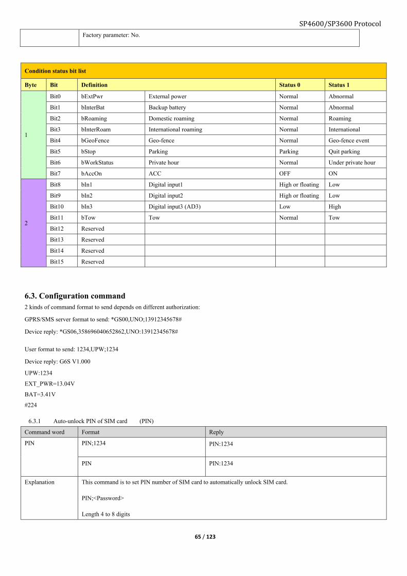
SP4600/SP3600 Protocol
65 / 123
Factory parameter: No.
Condition status bit list
Byte Bit Definition Status 0 Status 1
1
Bit0 bExtPwr External power Normal Abnormal
Bit1 bInterBat Backup battery Normal Abnormal
Bit2 bRoaming Domestic roaming Normal Roaming
Bit3 bInterRoam International roaming Normal International
Bit4 bGeoFence Geo-fence Normal Geo-fence event
Bit5 bStop Parking Parking Quit parking
Bit6 bWorkStatus Private hour Normal Under private hour
Bit7 bAccOn ACC OFF ON
2
Bit8 bIn1 Digital input1 High or floating Low
Bit9 bIn2 Digital input2 High or floating Low
Bit10 bIn3 Digital input3 (AD3) Low High
Bit11 bTow Tow Normal Tow
Bit12 Reserved
Bit13 Reserved
Bit14 Reserved
Bit15 Reserved
6.3. Configuration command 2 kinds of command format to send depends on different authorization:
GPRS/SMS server format to send: *GS00,UNO;13912345678#
Device reply: *GS06,358696040652862,UNO:13912345678#
User format to send: 1234,UPW;1234
Device reply: G6S V1.000
UPW:1234
EXT_PWR=13.04V
BAT=3.41V
#224
6.3.1 Auto-unlock PIN of SIM card (PIN)
Command word Format Reply
PIN PIN;1234 PIN:1234
PIN PIN:1234
Explanation This command is to set PIN number of SIM card to automatically unlock SIM card.
PIN;<Password>
Length 4 to 8 digits

SP4600/SP3600 Protocol
66 / 123
Factory default: PIN;1234
6.3.2 SMS service center number (SCN)
Command word Format Reply
SCN SCN;+8613800200500 SCN:+8613800200500
SCN SCN:+8613800200500
Explanation This command is to change SMS center number
SCN;<Number>
20 digits, must with “+country code” in front of phone number, default no need to set this number. Change to another
SIM card device will automatically read renew SCN setting.
Note: “+” is a must for country code.
Default: SCN
6.3.3 Set APN (APN)
Command word Format Reply
APN APN;cmnet;usr;pw APN;cmnet;usr;pw
APN APN:cmnet
Explanation This command is a must for GPRS connectivity.
<APN>: 1 to 64 characters
<user name>: 0 to 32 characters
<password>: 0 to 32 characters
If there is not username and password for APN, command could be:
APN;<APN>
Note: Device already save some APN information, it the SIM card is recognized it will fulfill APN automatically
Default: Null
6.3.4 Set GPRS main server (SVR)
Command word Format Reply

SP4600/SP3600 Protocol
67 / 123
SVR Set as TCP socket:
SVR;114.142.154.28;3032;;0;0
or
SVR;www.anytracking.net;3032;;0;0
Set as UDP socket
SVR;114.142.154.28;;3032;1;1
or
SVR;www.anytracking.net;;3032;1;1
Delete main server:
SVR;
Set as TCP socket:
SVR:114.142.154.28;3032;;0;0
or
SVR:www.anytracking.net;3032;;0;0
Set as UDP socket
SVR:114.142.154.28;;3032;1;1
or
SVR:www.anytracking.net;;3032;1;1
Reply:
SVR:
SVR SVR:114.142.154.28;3032;;0;0
Explanation This command is to set GPRS server.
SVR;<Ip address>;<Tcp Port>;<Udp Port>;<Mode>;<Enable ACK>
<Ip address>:IP or domain name, 64 characters maximum
<Tcp Port>:TCP port
<Udp Port>:UDP port
<Mode>:
“0”:TCP mode
“1”:UDP mode
“2”:TCP channel for command, UDP channel for data report
<Enable ACK>:
“0”:Disable
“1”:Enabled for UDP, this is default setting
“2”:Enabled for UDP and TCP both.
Note: <Enable ACK>: “1”: data is sent via UDP channel from device , server must responds with any data in 15 seconds,
otherwise device will consider UDP connection is dead and save data to its internal flash storage.
Factory default:
6.3.5 Set GPRS backup server (BSV)
Command word Format Reply

SP4600/SP3600 Protocol
68 / 123
BSV Set as TCP socket:
BSV;114.142.154.28;3032;;0;0
or
BSV;www.anytracking.net;3032;;0;0
Set as UDP socket
BSV;114.142.154.28;;3032;1;1
or
BSV;www.anytracking.net;;3032;1;1
Delete main server:
BSV;
Set as TCP socket:
BSV:114.142.154.28;3032;;0;0
or
BSV:www.anytracking.net;3032;;0;0
Set as UDP socket
BSV:114.142.154.28;;3032;1;1
or
BSV:www.anytracking.net;;3032;1;1
Reply:
BSV:
BSV BSV:114.142.154.28;3032;;0;0
Explanation This command is to set backup GPRS server when main server is inavailable.
BSV;<Ip address>;<Tcp Port>;<Udp Port>;<Mode>;<Enable ACK>
<Ip address>:IP or domain name, 64 characters maximum
<Tcp Port>:TCP port
<Udp Port>:UDP port
<Mode>:
“0”:TCP mode
“1”:UDP mode
“2”:TCP channel for command, UDP channel for data report
<Enable ACK>:
“0”:Disable
“1”:Enabled for UDP, this is default setting
“2”:Enabled for UDP and TCP both.
Note: <Enable ACK>, data is sent via UDP channel from device , server must respond with any data in 15 seconds,
otherwise device will consider UDP connection is dead and save data to its flash storage.
Factory default:
6.3.6 Records batch process (BDU)
Command word Format Reply
BDU BDU;1
BDU1;20
BDU:1
BDU1:20
BDU
BDU1
BDU:1
BDU1:20

SP4600/SP3600 Protocol
69 / 123
Explanation This command is to pack multiple position as a packet and report to server to save GPRS data flow, but it will affect the
real time report to server. Once the pre set value is met (regular packet/serial port packet) device will report immediately,
and reset the counter.
BDU;<Parameter>
This is to set regular packet threshold
BDU1;<Parameter>
This is to set serial port packet threhold
<Parameter>: range is “1 to 255”.
“1” means each position packet will be reported to server immediately.
e.g.:
BDU:10 means device waits for 10 regular position packets to pack as 1 packet to report
BDU1;30 means device waits for 30 packets from serial link to pack as 1 packet to report
Note:
1, Either BDU or BDU1 is met, device will report instantly.
2, Event report always immediately
Default:
BDU;1
BDU1;1
6.3.7 GPRS server report interval mode (SVP)
Command word Format Reply
SVP SVP;1;15S;G;B SVP:1;15S;G;B
SVP;1 SVP:1;15S;G;B
Explanation This command is set report interval of mode0 (static) and mode1 (dynamic)
SVP;<Mode>;<Interval>;<Report mode>;<Data format>
<Mode>:
“0”: Report mode0
“1”: Report mode1, valid only when command DNU is enabled.
<Interval>: range is “5 to 900 seconds”, “15 to 59 minutes”, “1to 720 hours”
<Report mode>:
“O”: Disable
“G”: GPS information prior
“A”: GPS and GSM information

SP4600/SP3600 Protocol
70 / 123
<Data format>:
“O”: Device will not generate data (record)
“B”: HEX
“T”: ASCII
Default:
SVP:0;30S;G;B,
SVP:1;600S;G;B
6.3.8 SMS server report interval mode (SSP)
Command word Format Reply
SSP SSP;1;12H;G;T SSP:1;12H;G;T
SSP SSP:1;12H;G;T
Explanation This command is to set mode0 and mode1 report interval for SMS server
SSP;<Mode>;<Interval>;<Report mode>;<Data format>
<Mode>:
“0”: Report mode0
“1”: Report mode1, valid only when command DNU is enabled.
<Interval>: range is “5 to 900 seconds”, “15 to 59 minutes”, “1 to 720 hours”
<Report mode>:
“O”: Disable
“G”: GPS information prior, otherwise use GSM tower position instead, GSM tower uses HEX format.
“A”: GPS and GSM information
<Data format>:
“O”: Device will not generate data
“T”: Text
Default:
SSP:0;30M;O;T
SSP:1;30M;O;T

SP4600/SP3600 Protocol
71 / 123
6.3.9 User report interval (USP)
Command word Format Reply
USP USP;1;12H;G;W USP:1;12H;G;W
USP;0 USP:0;12H;G;W
Explanation This command is to set mode0 and mode1 report interval to user0 and user1.
USP[ID]; <Mode>;<Interval>;<Report mode>;<Data format>
[ID]:
“0”: User0
“1”: User1
<Mode>:
“0”: Report mode0
“1”: Report mode1, valid only when command DNU is enabled.
<Interval>: range is “5 to 900 seconds”, “15 to 59 minutes”, “1to 720 hours”
<Report mode>:
“O”: Disable
“G”: GPS information prior, otherwise use GSM tower position instead, GSM tower uses HEX format.
“L”: Periodical voice call (Voice monitoring)
<Data format>:
“O”: Device will not generate data
“T”: Text
“W”: Map hyper link
Note: If <Data format> set as “W”, device that has GPS fixed will send URL0, GPS unfixed will send URL1 (GSM),
otherwise will send text format.
Default:
USP:0;24H;G;T
USP:1;24H;O;T
USP1:0;24H;G;T
USP1:1;24H;O;T
6.3.10 SMS server number configuration (SSN)
Command word Format Reply

SP4600/SP3600 Protocol
72 / 123
SSN SSN;13912345678
or
SSN;+8613912345678
SSN;
SSN:13912345678
or
SSN:+8613912345678
SSN:
SSN SSN:+8613912345678
Explanation This command is to set phone number as SMS server which has administrator permission to access command list.
SSN;<Phone number>
Range is “0 to 20” digits
Default: SSN:
6.3.11 Set SMS forwarding (SMT)
Command word Format Reply
SMT Forward to SMS server
SMT 0;+8613926442537;A
Forward to user0
SMT0;+8613926442537;U;0
Forward to user1
SMT:+8613926442537;U;1
Forward to GPRS server
SMT0;+8613926442537;G
Reply
SMT:+8613926442537;A
SMT:+8613926442537;U;0
SMT:+8613926442537;U;1
SMT:+8613926442537;G
SMT0 SMT0: +8613926442537;U;0
Explanation SMT[ID];<Paramter1>;<Parameter2>;<Parameter3>
Device will forward SMS that from number <Parameter1> to <Parameter2>
[ID]: range is “0 to 2”
<Parameter1>: Incoming phone number
<Parameter2>: Forward to here
“U”: User
“A”: SMS server
“G”: GPRS server
<Parameter3>:
When <Parameter2> set as “U”
“0”: User0
“1”: User1
Default:

SP4600/SP3600 Protocol
73 / 123
6.3.12 Motion sensor configuration (STP)
Command word Format Reply
STP STP;1800 STP:1800
STP STP:1800
Explanation This command is to set threshold duration from stop status to parking status
STP;<Duration time>
<Duration time>:
Range is “1 to 1800”, unit is “second”.
If device keep stop over this threshold value, vehicle will be considered as parking
Default:STP;600
6.3.13 Reboot device (RST)
Command word Format Reply
RST RST RST
Explanation Device will reboot without replying
When device receives RST command it is under data transmitting status it will wait 60 seconds most before executing
this command.
6.3.14 Time zone configuration (TZN)
Command word Format Reply
TZN TZN;8:00 TZN:8:00
TZN TZN:8:00
Explanation This command is to set your local time zone, and display local time in your SMS.
TZN;<Hour>:<Minute>
Range is “-13:00 to 13:00”,
Minus represents west zone, positive represents east zone
Default:TZN:0:00
6.3.15 Daylight saving configuration (DST)
Command word Format Reply

SP4600/SP3600 Protocol
74 / 123
DST Format1:
DST;03.27;10.01;00:00
Format2:
DST;03.F5;10.A0;00:00
Format1:
DST:03.27;10.01;00:00
Format2:
DST:03.F5;10.A0;00:00
DST DST:03.F5;10.A0;00:00
Explanation This command is to set daylight saving feature
DST;<Parameter1>;<Parameter2>;<Parameter3>
Set daylight-saving time.
<Parameter>: start date and second parameter is finish date. Start and finish time is decided by the third parameter. This
function only based on the user's cell phone.
Format 1 “DST;03.27;10.01;00:00” Para1-“03.27”: Daylight saving time start date. format is “month month. day day”.
“03.27” represents March 27.
<Parameter2>: “10.01”: Daylight saving time end date. format is “month month. day day”.
“10.01” represents October 1st.
<Parameter3>: “00:00”:start and end time (hour/min/sec), format is “hour hour: minute minute”.”00:00” represents time
is “00:00”
Format 2 “DST;03.F5;10.A0;00:00”:
<Parameter1>: “03.F5”: Daylight saving time start date, format is “month month. week day of week”. Week can be set
“A B C D F”. "A" for the first week, "B" for the second week, and so on, the fifth week or last week can use the "F" to
represent. Day of week can be set to “0 1 2……6”. Beginning on Sunday (“0” represent Sunday) to Saturday (“6”
represent Saturday). ”03.F5” represents Friday on the last week of march.
<Parameter2>: “10.A0”: Daylight saving time end date, format is same as para1. “10.A0” represents Sunday on the first
week of October
<Parameter3>: “00.00”:start and end time (hour/min/sec), format is “hour hour: minute minute”.”00:00” represents time
is “00:00”
Default: DST;00.00;00.00;00:00
Default: DST;0
6.3.16 Enable daylight saving feature (STO)
Command word Format Reply
STO STO;1 STO:1
STO STO:1
Explanation This command is to toggle daylight saving feature.
STO;<Parameter>
1: Enable
0: Disable
Default: STO:0

SP4600/SP3600 Protocol
75 / 123
6.3.17 Power supply event (PTH)
Command word Format Reply
PTH PTH;45;35 PTH:45;35
PTH PTH:45;35
Explanation This command is to set threshold value for power supply event.
PTH;<Parameter1>;<Parameter2><Duration time>
Low voltage event for external power and backup battery.
<Parameter1>: External power threshold, range is “0 to 999”, unit is 100mV.
<Parameter2>: Backup battery threshold, range is “0 to 999”, unit is 100mV.
<Duration time>: unit is second, range is “0 to 255”
Default: PTH:0;0
6.3.18 Report interval mode switching condition (DNU)
Command word Format Reply
DNU DNU;1 DNU:1
DNU DNU:1
Explanation This command is to set conditions to switch between mode0 and mode1
DNU;<Parameter>
HEX, Range is “0 to FF”
Bit0:Stop
Bit1:Domestic roaming
Bit2:International roaming
Bit3:Using backup battery
Bit4:ACC OFF
”0”: Disable
“1”:Enable
DNU;0 means device always stick to mode0 interval only.
Default: DNU;0

SP4600/SP3600 Protocol
76 / 123
6.3.19 Fixed distance report and corner turning report (DIS)
Command word Format Reply
DIS DIS;0;7 DIS:0;7
DIS DIS:0;7
Explanation This command is to set threshold value for cornering and distance report
DIS;<Distance><Angle>
Device will report once fixed distance or cornering angle is satisfied
<Distance>: range is “0 to 255”, unit is “0.1km”.
<Angle>: range is “3 to 20”, unit is “degree”
Default:DIS;0;7
6.3.20 Analog input event condition (ATH)
Command word Format Reply
ATH ATH;80;250;3 ATH:80;250;3
ATH ATH:80;250;3
Explanation This command is to set input voltage outside the range, power supply event will be triggered.
ATH[ID];<Lower limit>;<Upper limit>;<Duration>
<ID>:AD channel, range is “0 or 1”
0: AD1, valid only when AD1 set as analog.
1: AD2, valid only when AD2 set as analog.
<Lower limit>: range is “0 to 999”, unit is 100mV.
<Upper limit>: range is “0 to 999”, unit is 100mV.
<Duration time>: unit is second, range is 0 to 255.
Default:
ATH0;0;10;3
ATH1;0;10;3
6.3.21 Voice functionality configuration (VOE)
Command word Format Reply
VOE VOE;1;1
VOE
VOE:1;1
VOE:1;1

SP4600/SP360 Protocol
77 / 123
Explanation This command is to toggle voice feature
VOE;<Voice call mode>;<SOS mode>;<SOS I/O port ID>
<Voice call mode>:
“0”: Disable call in and out
“1”: Enable call in and out
<SOS mode>:
“0”: Disable voice SOS
“1”: Enable voice SOS (conversation mode)
“2”: Enable voice SOS (Listening only)
<SOS I/O input ID>:
Assign SOS input channel, range is “0 to 1”.
Note1:
If <Voice call mode> set as “0”, only admin/user PRQ functionality available.
Note2:
If <Voice call mode> set as “0”,
>Incoming phone number in white list,
If it is PRQ authorization, device will hang up. If it is monitoring authorization, device will pick up. If its hot line
authorization, device will pick up.
>Incoming phone number is admin (SMS server), device will pick up in 15 seconds.
Default: VOE:1;0;
6.3.22 Phone number white list (PWL)
Command word Format Reply
PWL PWL;S;1;14714821165
PWL;R;1
PWL:S;1;14714821165
PWL;R;1;14714821165
PWL;R;1-8 PWL:R;1;;2;;3;;4;;5;;6;;7;;8;
Explanation This command is to save phone number as white list number and assign different authorization to them
PWL;S;<Index>;<Phone number list>;<…>
Delete all the numbers in white list:
PWL;S;
Delete first number in white list
PWL;S;1;
Add first and second number to white list
PWL;S;1;180XXXXXXXX;2;13512345678”
Query white list
PWL;R;<Index>

SP4600/SP3600 Protocol
78 / 123
<Index>:
2 Formats:
Format1:Index number; Index number…
Format2: Start index- End index
Note:
>Single command only available to query 8 numbers in a time.
>”X” means any number will be ok.
>Index number range is “1 to 16”, start must small than end
>If one number has monitoring and hotline authorization both, then only monitoring authorization is valid.
e.g.:
Query first to eighth numbers in white list:
PWL;R;1-8
Query first and second numbers in white list
PWL;R;1;2
6.3.23 Query current position authorization list (QWL)
Command word Format Reply
QWL QWL;1-3;7 QWL:1,2,3;7
QWL; QWL:
Explanation This is to enable phone number from white list for current position query purpose, device will reject the call and reply a
SMS with current position.
QWL;<Index>
Explanation:
<Index>: Assign numbers to have “Query current position authorization” from white list.
e.g.: Assign number 1,2,3,7 from white list
QWL;1-3;7
or
QWL;1;2;3;7
Default: QWL
6.3.24 Voice monitoring authorization list (MWL)
Command word Format Reply
MWL MWL;1-3;7 MWL:1;2;3;7
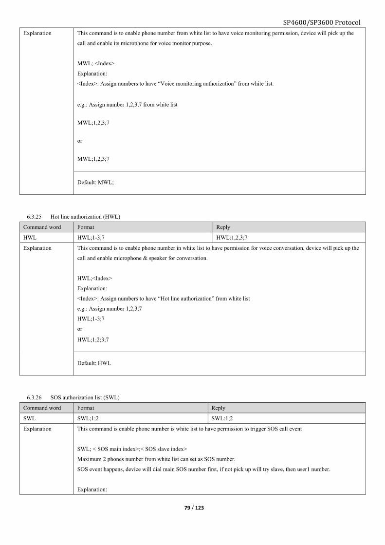
SP4600/SP3600 Protocol
79 / 123
Explanation This command is to enable phone number from white list to have voice monitoring permission, device will pick up the
call and enable its microphone for voice monitor purpose.
MWL; <Index>
Explanation:
<Index>: Assign numbers to have “Voice monitoring authorization” from white list.
e.g.: Assign number 1,2,3,7 from white list
MWL;1,2,3;7
or
MWL;1,2,3;7
Default: MWL;
6.3.25 Hot line authorization (HWL)
Command word Format Reply
HWL HWL;1-3;7 HWL:1,2,3;7
Explanation This command is to enable phone number in white list to have permission for voice conversation, device will pick up the
call and enable microphone & speaker for conversation.
HWL;<Index>
Explanation:
<Index>: Assign numbers to have “Hot line authorization” from white list
e.g.: Assign number 1,2,3,7
HWL;1-3;7
or
HWL;1;2;3;7
Default: HWL
6.3.26 SOS authorization list (SWL)
Command word Format Reply
SWL SWL;1;2 SWL:1;2
Explanation This command is enable phone number is white list to have permission to trigger SOS call event
SWL; < SOS main index>;< SOS slave index>
Maximum 2 phones number from white list can set as SOS number.
SOS event happens, device will dial main SOS number first, if not pick up will try slave, then user1 number.
Explanation:

SP4600/SP3600 Protocol
80 / 123
< Index>: Assign number 1,2 to have “SOS authorization” from white list
SWL;1,2
Default: SWL
6.3.27 Geo-fence configuration (GFS)
Command word Format Reply
GFS GFS0;1;1;25.31;113.0;1000
GFS0;P;0;25.31;113.0;1;1000
GFS0;S;10;100
GFS0;T;7F;12:00-14:00
GFS0;1;1;25.31;113.0;1000
GFS0;P;0;25.31;113.0;1;1000
GFS0;S;10;100
GFS0;T;7F;12:00-14:00
GFS0
GFS0;P;0
GFS0;P;1
GFS0;S
GFS0;T
GFS0:1;8001;25.310000;113.000000;1000
GFS0:P;0;25.310000;113.000000
GFS0:P;1;1000
GFS0:S;10;100
GFS0:T;7F;12:00-14:00;00:00-00:00;00:00-00:00
Explanation ■It supports circular, rectangle, and polygon Geo-fence
GFS[ID];<vertex_cnt><;flag><;para….>
Explanation:
<ID>: Geo-fence ID, range is “0 to 155”.
“0 to 27” represents 28 Geo-fences that support circle/ rectangle/ polygon.
“28 to 155” represents 128 Geo-fences that support circle shape only
<vertex_cnt>: number of vertex,
”0”: Delete this Geo-fence
“1”: Set as circle shape.
“2”: Set as rectangle shape.
“3 or bigger value” Set as polygon shape
Flag to configure Geo-fence attribution:
Bit0 Enable entering detection
Bit1 Enable leaving detection
Bit2 Enable inside speed range detection
Bit3 Enable outside speed range detection
Bit4 Enable valid time period
Bit5 Reserved
Bit6 Reserved

SP4600/SP3600 Protocol
81 / 123
Bit7 Reserved
Bit8 Reserved
Bit9 Reserved
Bit10 Reserved
Bit11 Reserved
Bit12 Reserved
Bit13 Time validation flag
Bit14 Speed validation flag
Bit15 Geo-fence validation flag
“Bit0 to Bit1”: one of them must be “1”. System will force “Bit0” as “1” when set “Bit0 and Bit1” as “00”.
“Bit3 to Bit2”:
“00”: Represents detecting device in or out of Geo-fence, not refer speed.
“01”: Represents only inside the preset speed range, device to detect in or out of Geo-fence.
“10”: Represents only outside the preset speed range, device to detect in or out of Geo-fence.
“11”: System will treat it as “00”.
“Bit4”:
“0”: Disable valid time period
“1” Enable only in time period, device to detect in or out of Geo-fence
Note: Only if time and speed condition being satisfied, device will report Geo-fence event, otherwise device just detect
current status.
“Bit5 to Bit12”:
Reserved.
“Bit13”: Time validation flag, “1” such condition is enabled
“Bit14”: Speed validation flag, “1” such condition is enabled.
“Bit15”: Geo-fence validation flag, “1” such condition is enabled.
<Para…>” Parameter of circle or rectangle Geo-fence, if <vertex_cnt> value is “1” or “2”, Geo-fence has parameter to
set:
For circle Geo-fence, <Para…> is <center latitude, center longitude, radius>.
For rectangle Geo-fence, <Para…> is <vertex1 latitude, vertex1 longitude, vertex2 latitude, vertex2 longitude…>
Query Geo-fence configuration:
GFS[ID]
Set Geo-fence
GFS[ID];P;para_ID;para_val<;para_ID;para_val>…
Explanation:
para_ID: Geo-fence ID
For circle, “0” means center latitude and longitude, “1” means radius.
For rectangle, “0” means vertex1 latitude and longitude, “1” means vertex2 latitude and longitude.
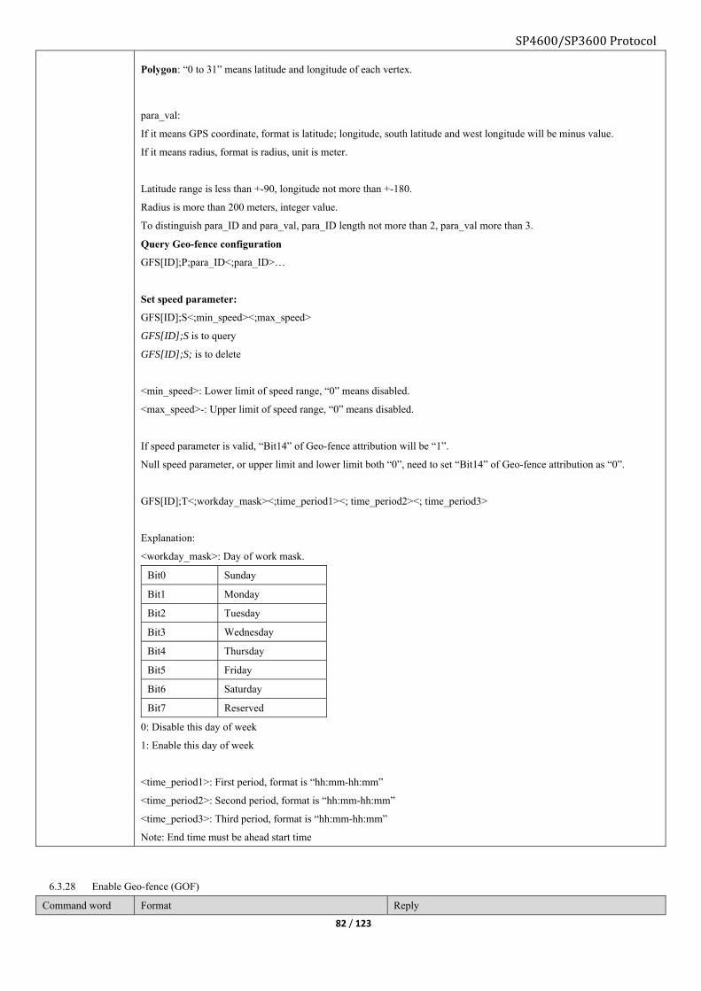
SP4600/SP3600 Protocol
82 / 123
Polygon: “0 to 31” means latitude and longitude of each vertex.
para_val:
If it means GPS coordinate, format is latitude; longitude, south latitude and west longitude will be minus value.
If it means radius, format is radius, unit is meter.
Latitude range is less than +-90, longitude not more than +-180.
Radius is more than 200 meters, integer value.
To distinguish para_ID and para_val, para_ID length not more than 2, para_val more than 3.
Query Geo-fence configuration
GFS[ID];P;para_ID<;para_ID>…
Set speed parameter:
GFS[ID];S<;min_speed><;max_speed>
GFS[ID];S is to query
GFS[ID];S; is to delete
<min_speed>: Lower limit of speed range, “0” means disabled.
<max_speed>-: Upper limit of speed range, “0” means disabled.
If speed parameter is valid, “Bit14” of Geo-fence attribution will be “1”.
Null speed parameter, or upper limit and lower limit both “0”, need to set “Bit14” of Geo-fence attribution as “0”.
GFS[ID];T<;workday_mask><;time_period1><; time_period2><; time_period3>
Explanation:
<workday_mask>: Day of work mask.
Bit0 Sunday
Bit1 Monday
Bit2 Tuesday
Bit3 Wednesday
Bit4 Thursday
Bit5 Friday
Bit6 Saturday
Bit7 Reserved
0: Disable this day of week
1: Enable this day of week
<time_period1>: First period, format is “hh:mm-hh:mm”
<time_period2>: Second period, format is “hh:mm-hh:mm”
<time_period3>: Third period, format is “hh:mm-hh:mm”
Note: End time must be ahead start time
6.3.28 Enable Geo-fence (GOF)
Command word Format Reply
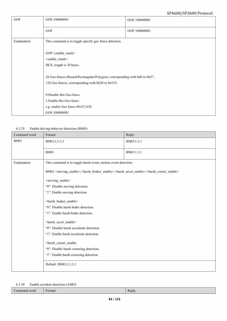
SP4600/SP3600 Protocol
83 / 123
GOF GOF;108000001 GOF:108000001
GOF GOF:108000001
Explanation This command is to toggle specify geo fence detection.
GOF<;enable_mask>
<enable_mask>:
HEX, length is 20 bytes.
28 Geo-fences (Round/Rectangular/Polygon), corresponding with bit0 to bit27,
128 Geo-fences, corresponding with bit28 to bit155,
0:Disable this Geo-fence
1:Enable this Geo-fence
e.g. enable Geo fence #0,#27,#28
GOF;108000001
6.3.29 Enable driving behavior detection (BMO)
Command word Format Reply
BMO BMO;1;1;1;1 BMO:1;1;1
BMO BMO:1;1;1
Explanation This command is to toggle harsh event, motion event detection.
BMO; <moving_enable>;<harsh_braker_enable>;<harsh_accel_enable>;<harsh_corner_enable>
<moving_enable>
“0”: Disable moving detection.
“1”: Enable moving detection.
<harsh_braker_enable>
“0”: Disable harsh brake detection.
“1”: Enable harsh brake detection.
<harsh_accel_enable>
“0”: Disable harsh accelerate detection.
“1”: Enable harsh accelerate detection.
<harsh_corner_enable.
“0”: Disable harsh cornering detection.
“1”: Enable harsh cornering detection.
Default: BMO;1;1;1;1
6.3.30 Enable accident detection (AMO)
Command word Format Reply

SP4600/SP3600 Protocol
84 / 123
AMO AMO;1;1 AMO:1;1
AMO AMO:1;1
Explanation This command is to toggle accident & turn over event.
AMO; <crash_enable>;<turn_over_enable>
<crash_ enable>
“0”: Disable rear collision detection.
“1”: Enable rear collision detection.
Note: Sensor will judge front/rear by itself.
<turn_over_enable>
“0”: Disable turn over detection.
“1”: Enable turn over detection.
Default: AMO;1;1
6.3.31 Device install direction (BDS)
Command word Format Reply
BDS BDS;1 BDS:1
BDS BDS:1
Explanation Device must be installed as certain direction to have proper sensor functionality.
BDS;<direction>
<Direction>: range is “0 to 3”
Note: Please face the side with GPS antenna to the sky
Default: BDS;0
6.3.32 Enable odometer counter (MGE)
Command word Format Reply

SP4600/SP3600 Protocol
85 / 123
MGE MGE;1 MGE:1
MGE MGE:1
Explanation This command is toggle mileage feature
MGE;<mode>
<mode>
“0”: Disable
“1”: Enable
Default: MGE:0
6.3.33 Odometer initial mileage (MGS)
Command word Format Reply
MGS MGS;1000 MGS:1000
MGS MGS:1000
Explanation This command is set initial value of mileage, device will accumulate mileage based on this value and report to server
MGS;<data>
<data>: Decimal, range is “0 to 4294967295”, unit is “meter”
6.3.34 Over speed mode configure (SPO)
Command word Format Reply
SPO SPO;0 SPO:0
SPO SPO:0
Explanation This command is set over speed mode
SPO;<Mode>
<Mode>:
0: disable over speed event report
1: speed enters the range of <Max><Mini>
2: speed leaves the range of <Max><Mini>
3: speed enters or leaves the range of <Max><Mini>
Default: SPO:0
6.3.35 Over speed configuration (SPS)
Command word Format Reply
SPS SPS;100;1;10 SPS:100;1;10

SP4600/SP3600 Protocol
86 / 123
SPO SPO:100;1;10
Explanation This command is to set speed range for over speed event.
SPS;<Max>;<Mini>;<Duration time>
<Max>:Upper speed value, unit is “km/h”
<Mini>:Lower speed value, unit is “km/h”
<Duration time>: If current speed match with over speed condition and last for this long, over speed event report will be
triggered.
Range is “1 to 65535”, unit is “second”
Default:SPS:100;1;10
6.3.36 Enable idle detection (ILO)
Command word Format Reply
ILO ILO;1 ILO:1
ILO ILO:1
Explanation This command is to toggle idle status detection.
ILO;<Mode>
<Mode>:
“0”:disable
“1”:enable
Default: ILO;0
6.3.37 Idle status configuration (ILS)
Command word Format Reply
ILS ILS;100;100 ILS:100:100
ILS ILS:100:100
Explanation ILS;<Stop time>;<Move time>
<Stop time>: range is “1 to 65535”, unit is “second”, if device keep stop for this long (IG on), will be considered as idle.
<Move time>: range is “1 to 65535”, unit is “second”, if device moving again or IG off duration over this value, will be
considered as Quit idle
Default:ILS;100;100
6.3.38 Enable engine hour counter (ETO)
Command word Format Reply
ETO ETO;1 ETO:1

SP4600/SP3600 Protocol
87 / 123
ETO ETO:1
Explanation This command is to toggle engine hour counter
ETO;<Mode>
<Mode>:
“0”: Disable
“1”: Enable
Default: ETO;0
6.3.39 Set engine hour counter (ETS)
Command word Format Reply
ETS ETS;88888:0:0;1 ETS;88888:0:0;1
ETS ETS:88888:0:0;1
Explanation This command is to set initial engine hour, device will accumulate based on this value.
ETS;<Hour>;<Minute>;<Second>
<Hour>: 5 digits maximum
<Minute>: 2 digits maximum
<Second>: 2 digit maximum
Range is “0:0:0 to 99999:0:0”, the <Engine hour counter> in IG ON report will accumulate base on this value.
<I/O port>
To assign which port as engine status input port.
“0”: AD1, only valid when “AD1/IN3” set as digital
“1”: AD2, only valid when “AD2/IN4” set as digital
below conditions must be satisfied:
>AIM set as digital
>DIM mode0
6.3.40 Health check report (HTM)
Command word Format Reply
HTM HTM;1;1 HTM:1;1
HTM HTM:1;1
Explanation This command is to set health check packet report interval to GPRS server.
HTM;<Mode>
HTM;<Mode>;<Time>
Query health check report:
Send (GPRS/SMS server):
*GS00,HTM;0#
Reply:

SP4600/SP3600 Protocol
88 / 123
*GS06,356496042331108,HTM:0#
*GS06,356496042331108,030005170613,87,SYS:G6S,GPS:A;6;N23.164422;E113.428712,COT:,ADC:13.00;3.40;0.00;
0.00,DTT:84;C0;0;0,ETD:64#
Set report every 12 hours automatically:
Send:
*GS00,HTM;1;12#
Reply:
*GS06,356496042331108,HTM:1:12#
<Mode>:
0:Query current device health only
1: Set periodical report
<Time>: Report interval, only valid when mode set as “1”, range is “0 to 255”, unit is hour, “0” means do not report.
Report type: defined as “event”, set by command EUP
Data field: set by command ADM
<ETD>, HEX, 1byte
Bit Content 0 1
bit0 Socket1Connection status Disconnected Connected
bit1 Socket2 Connection status Disconnected Connected
bit2 Socket3 Connection status Disconnected Connected
bit3 Socket4 Connection status Disconnected Connected
bit4 Socket5 Connection status Disconnected Connected
bit5 2D sensor status Abnormal Normal
bit6 Flash storage status Abnormal Normal
bit7 Vibration sensor status Still Move
Explanation:
MOT_MOV: Move
MOT_STA: Still
FSH_OK:Flash storage status
FSH_ERR:Flash error
2D_OK:2D normal
2D_ERR:2D abnormal
SOC_OK:Socket connection is ok
SOC_ERR:Socket connection error
Note:
Query health check information: Isolated from each connectivity type.
Periodical health check information report: EUP7 is enabled and EMS is allowed.
Default: HTM;0;0
6.3.41 Set assist-GPS (AGP)

89 / 123
Command word Format Reply
AGP AGP;1 AGP:1
AGP AGP:1
Explanation This command is to toggle Assisted GPS feature
AGP;<mode>
<mode>:
“0”: disable A-GPS
“1”:enable A-GPS
Factory default: AGP;0
6.3.42 Save current configuration as profile (SCF)
Command word Format Reply
SCF SCF;1 SCF:1
SCF SCF:1
Explanation Save current global setting to device, 3 profile slots available.
Format:
SCF;<Mode>
<Mode>: Range is “0 to 2”
Default:
6.3.43 Load pre-saved configuration profile (RCF)
Command word Format Reply
RCF RCF;1 RCF:1
Explanation Recover global setting from device flash, it will cost some time and device will reboot when finished.
Format:
RCF;<Mode>
<Mode>: Range is “0 to 2”
6.3.44 Private hour mode configuration (PVM)
Command word Format Reply
PVM PVM;1111100;00:00-08:30;11:30-13:30;17:30-23:59 PVM;1111100;00:00-08:30;11:30-13:30;17:30-23:59
PVM PVM:1111100;00:00-08:30;11:30-13:30;17:30-23:59
SP4600/SP3600 Protocol

SP4600/SP3600 Protocol
90 / 123
PVM;<mode><diid><workdaymask><hh1:mm1-hh2:mm2><hh1:mm1-hh2:mm2><hh1:mm1-hh2:mm2>
4 kinds of private mode, each mode has different trigger condition and report different to server:
Mode Name Trigger condition Report data string
0 Disable As usual
1 Full manual If digital input is “true”, device will
switch to “Full manual” private mode,
otherwise as usual
Not report GPS/GSM position,
Report device status (DTT)
2 Half manual If digital input is “true”, and under
private hour range, device will switch
to “Half manual” private mode,
otherwise as usual
Not report GPS/GSM position,
Report device status (DTT)
3 Automatically According to private hour range setting
only, device will switch to
“Automatically” private mode,
otherwise as usual
Not report GPS/GSM position,
Report device status (DTT)
4 Automatically
private activity
According to private hour range setting
only, device will switch to
“Automatically” private mode,
otherwise as usual
Report as usual,
Report device status (DTT)
Note:
4 digital input channels, range is “0 to 3”, first 2 are low level trigger, last 2 are high level trigger.
Workday mask, “1” is working day, “0” is private day.
1 1 1 1 1 0 0
Mon Tue Wed Thu Fri Sat Sun
<mode>
0: Disable private hour mode
Command format: PVM;0
1: Full manual
Command format: PVM;1;<diid>
<diid>: Digital input channel, range is “0 to 3”
2: Half-manual
Command format: PVM;2;<diid>;<workdaymask>;<hh1:mm1-hh2:mm2>..
<diid>: Digital input channel, range is “0 to 3”
<workdaymask>: Working day mask
<hh1:mm1-hh2:mm2>: Private hour period on daily basis, 3 periods valid, at least set 1 period.

SP4600/SP3600 Protocol
91 / 123
3: Automatically
Command format: PVM;3;<workdaymask>;<hh1:mm1-hh2:mm2>..
<workdaymask>: Working day mask
<hh1:mm1-hh2:mm2>: Private hour period on daily basis, 3 periods valid, at least set 1 period.
4: Private activity monitoring
Command format: PVM;4;<workdaymask>;<hh1:mm1-hh2:mm2>..
<workdaymask>: Working day mask
<hh1:mm1-hh2:mm2>: Private hour period on daily basis, 3 periods valid, at least set 1 period.
Default: PVM;0
6.3.45 Private hour mode digital output configuration (POB)
Command word Format Reply
POB POB;1;1;4;5 POB:1;1;4;5
POB POB:1;1;4;5
Explanation This command is to configure digital output for private mode or private activity.
Disable: POB;0
Enable: POB;1;<DOID>;<DOMode>;<Interval>
<DOID>: Digital output channel ID, range is “0 to 2”
<DOMode>: Digital output wave shape mode, range is “0 to 7”
<Interval>: Output interval, range is “0 to 65535”, unit is second
Default: POB;0
6.3.46 1WIRE working mode (IBO)
Command word Format Reply
IBO IBO;0 IBO:0
IBO IBO:0
Explanation This command is to set what is current 1wire accessory connecting
Format: IBO;<mode>
<mode>:
0: Disable 1WIRE feature
1: Use ibutton key
2: Use DS18B20
3: Use ibutton key and DS18B20mode together
<IButton relevant mode>: when <Mode> as“1”or“3”,it has this data segment
0:No relevant mode
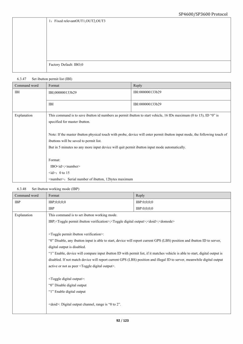
SP4600/SP3600 Protocol
92 / 123
1:Fixed relevantOUT1,OUT2,OUT3
Factory Default: IBO;0
6.3.47 Set ibutton permit list (IBI)
Command word Format Reply
IBI IBI;000000133b29 IBI:000000133b29
IBI IBI:000000133b29
Explanation This command is to save ibutton id numbers as permit ibutton to start vehicle, 16 IDs maximum (0 to 15), ID “0” is
specified for master ibutton.
Note: If the master ibutton physical touch with probe, device will enter permit ibutton input mode, the following touch of
ibuttons will be saved to permit list.
But in 5 minutes no any more input device will quit permit ibutton input mode automatically.
Format:
IBO<id>;<number>
<id>:0 to 15
<number>:Serial number of ibutton, 12bytes maximum
6.3.48 Set ibutton working mode (IBP)
Command word Format Reply
IBP IBP;0;0;0;0
IBP
IBP:0;0;0;0
IBP:0;0;0;0
Explanation This command is to set ibutton working mode.
IBP;<Toggle permit ibutton verification>;<Toggle digital output>;<doid>;<domode>
<Toggle permit ibutton verification>:
“0” Disable, any ibutton input is able to start, device will report current GPS (LBS) position and ibutton ID to server,
digital output is disabled.
“1” Enable, device will compare input ibutton ID with permit list, if it matches vehicle is able to start, digital output is
disabled. If not match device will report current GPS (LBS) position and illegal ID to server, meanwhile digital output
active or not as peer <Toggle digital output>.
<Toggle digital output>:
“0” Disable digital output
“1” Enable digital output
<doid>: Digital output channel, range is “0 to 2”.

SP4600/SP3600 Protocol
93 / 123
<domode>: Digital output level, “0” represents low level, “1” represents high level.
e.g.: if set as “0” when ACC on and there is illegal ibutton input, digital output will perform low level.
Default: IBP;0;0;0;0
6.3.49 Set 1WIRE temperature alarm range (TMP)
Command word Format Reply
TMP TMP;100;-10;5 TMP:100;-10;5
TMP TMP:100;-10;5
Explanation This command is to set out of temperature range alarm to server
Format:
TMP;<High_Temp>;<Low_Temp>
<High_Temp>: Upper limit, unit is Celsius, range is “-99.9 to 999.9”.
<Low_Temp>: Lower limit, unit is Celsius, range is “-99.9 to 999.9”
<Duration time>: Temperature stays inside range surpasses this value will trigger event, unit is second, range is 1 to
65535.
Default: TMP;100;-100;10
6.3.50 Server shift configuration (SVT)
Command word Format Reply
SVT SVT;1800;15 SVT:1800;15
SVT SVT:1800;15

SP4600/SP3600 Protocol
94 / 123
Explanation This command is to set backup server timeout.
Format
SVT;<shift timer>;<ACK timeout>
Explanation
<Shift timer>: When timer is up, device will try to reconnect with main server, unit is second, range is “60 to 65535”.
<ACK timeout>: Timeout threshold for server ACK packet, unit is second, range is “15 to 60”.
Default: SVT;1800;15
6.3.51 Set ibutton key special mode (IBE)
Command word Format Reply
IBE IBE;1 IBE:1
IBE IBE:1
Explanation This command is to toggle ibutton key special mode.
Format
IBE;<Mode>
<Mode>:
“0”: disable ibutton key verification (bypass mode)
“1”: enable ibutton key verification
Default: IBE;1
6.3.52 Define ibutton key special mode (IBS)
Command word Format Reply
IBS IBS;1;4;4;5;20 IBS:1;4;4;5;20
IBS IBS:1;4;4;5;20
Explanation This command is to set digital output mode for each output.
Format
IBS;<output1 level for relay>;<output2 level for LED when acc on>;<output3 level for buzzer when acc on>;
<output3 level for buzzer when ibutton key presents>;<delay time to cut ignition after engine off>.
<output1 level for relay>:
“0” output1 performs low level.
“1” output1 performs high level.
<output2 level for LED when acc on>:
Range from 0 to 7, refer command DOM1.
<output3 level for buzzer when acc on>:
Range from 0 to 7, refer command DOM2.

SP4600/SP3600 Protocol
95 / 123
<output3 level for buzzer when ibutton key presents>
Range from 0 to 7, refer command DOM3.
<delay time to cut ignition after engine off>
Range from 0 to 7, refer command DOM3.
ibutton special mode explanation:
1, set as special mode by command IBO;3
2, set command IBE, command IBS.
3, set wave shape by command DOM1, DOM2.
4, set 1wire event by command ESM, command EUP.
5, set input by command AIM, command ETS.
Default: IBS:0;4;4;5;20
6.3.53 Input event to activate serial port output (ITS)
Command word Format Reply
ITS ITS1;1;1;0;ABCDEF09876543210D0A ITS1:1;1;0;ABCDEF09876543210D0A
ITS0 ITS1:1;1;1;Hello
This command is to set serial port to send a customized string when input event being triggered.
Format:
ITS[ID];<interval><times><format><string>
[ID]: specify input event.
0: input1 event
1: input2 event
2: input3 event
3: input4 event
<interval>: interval between multiple times output, range is 0 to 30, unit is minutes.
<times>: specify how many times to repeat sending the customized string on serial port, range is 0 to 5, value 0 means
disabled.
<format>: define the string coding format.
0: HEX, number count in <string> should be even
1: ASCII
<string>: content of output on serial port, maximum length is 31 bytes.
Default:
ITS0;1;0;0
ITS1;1;0;0
ITS2;1;0;0
ITS3;1;0;0
6.3.54 Set USSD server (SUR)
Command word Format Reply

SP4600/SP3600 Protocol
96 / 123
SUR SUR; *126*118*725* SUR: *126*118*725*
SUR SUR: *126*118*725*
Explanation This command is to set USSD server address.
Format:
SVR;<USSD server address>
<USSD server address>: Maximum 32 bytes
Default: Null
6.3.55 USSD server report interval mode (SUP)
Command word Format Reply
SUP SUP;1;60S;G;T SUP:1;60S;G;T
SUP SUP:1;15S;G;T
Explanation This command is set report interval of mode0 (static) and mode1 (dynamic)
SUP;<Mode>;<Interval>;<Report mode>;<Data format>
<Mode>:
“0”: Report mode0
“1”: Report mode1, valid only when command DNU is enabled.
<Interval>: range is “60 to 900 seconds”, “15 to 59 minutes”, “1to 720 hours”
<Report mode>:
“O”: Disable
“G”: GPS information prior
“A”: GPS and GSM information both
<Data format>:
“O”: Device will not generate data (record)
“T”: ASCII
Default:
SUP:0;60S;G;B,
SUP:1;600S;G;B
6.4. Public command
6.4.1 Set user phone number (UNO)
Command word Format Reply
UNO UNO0;+8613912345678
UNO1;+8613912345678
UNO0:+8613912345678
UNO1:+8613912345678

SP4600/SP3600 Protocol
97 / 123
Delete user number:
UNO0;
UNO1;
Reply:
UNO0:
UNO1:
Explanation This command is set up 2 users phone number
2 user numbers are available: UNO0 and UNO1.
With the correct password, any phone number is able to use this command.
Default:
UNO0:
UNO1:
6.4.2 Set user command password (UPW)
Command word Format Reply
UPW Set user0 password: UPW0;1234
Set user1 password: UPW1;2234
UPW0:1234
UPW1:2234
Explanation Fix 4 digits, range is “0000 to 9999”
UPW0: Set user0 password
UPW1: Set user1 password
Default:
UPW0;1234
UPW1;1234
6.4.3 Motion sensor configuration (MOT)
Command word Format Reply
MOT MOT;0 MOT:0
MOT MOT:0
Explanation This command is to configure vibration sensor.
MOT;<Parameter>
<Parameter>:
0: Disable motion sensor, all kinds of report that relates with motion sensor will be disabled as well. If set as “0”, device
will be treated as “moving” all the time.
1: Enable motion sensor, high sensitivity.
2: Enable motion sensor, low sensitivity.
Default:MOT:1

SP4600/SP3600 Protocol
98 / 123
6.4.4 User command shortcut (USC)
Command word Format Reply
USC USC
USC1;B;NAM(,VER
USC;A; PRQ
USC1:B;NAM(,VER
Explanation USC[ID];<Parameter1>;<Command>
[ID]: range is “0 to 9”
<Parameter1>: English letter without case sensitive
<Command>:
If in the command there is character need to be converted, please refer chapter 3.2.2
Short command length is 50bytes maximum, reply message length is 70bytes maximum.
Up to 10 short commands is supported (USC0 to USC9).
e.g.: set “B” as short command for PRQ/STP,
send: USC;A;PRQ(,STP(;600
then command “password,A” equals commands PRQ and STP
Note: Only support user authorization commands to set as short command.
Factory default:
6.4.5 Firmware upgrade command (FWU)
Command word Format Reply
FWU FWU FWU
Explanation This is for over the air firmware upgrade.
Upgrade firmware on local, please refer chapter6.5
6.4.6 Abort ongoing upgrade process (FCL)
Command word Format Reply
FCL FCL
Explanation This command only effective when device is downloading firmware file from server.
6.4.7 Rollback to previous firmware version (FRC)
Command word Format Reply
FRC FRC FRC:1
FRC:0
Explanation 0: Roll back to previous version failed
1: Roll back to previous version succeeded
6.4.8 Audio configuration (AGN)

99 / 123
Command word Format Reply
AGN AGN0;7;7 AGN0:7;7
AGN AGN0:7;7
Explanation AGN[ID];<MIC gain>,<Speaker gain>
[ID]: Fix as “0”
<MIC gain>: range is “0 to 7”
<Speaker gain>: range is “0 to 7”
6.4.9 Device call back (CAL)
Command word Format Reply
CAL CAL;13812345678;1 CAL:13812345678;1
Explanation By sending this command device will call the phone number accordingly
CAL;<Phone number to call>;<Mode>
<Mode>:
“0”: Conversation mode
“1”: Listening only
6.4.10 Rename event for user report (ENM)
Command word Format Reply
ENM ENM25;ALARM:IO2_OFF;ALARM:IO2_ON ENM25:ALARM:IO2_OFF;ALARM:IO2_ON
ENM25 ENM25:ALARM:IO2_OFF;ALARM:IO2_ON
Explanation This command is to customize event name in the SMS message to user phone number.
ENM[Event ID];<Event status0 name>;<Event status1 name>
[Event ID]: range is “0 to 63”
<Event status0 name>: 15 bytes maximum
<Event status1 name>: 15 bytes maximum
Note: Combination event rename only can set on field <Event status0 name>.
6.4.11 Reset event report (ETC)
Command word Format Reply
ETC ETC ETC
Explanation To clear device reaction of event.
Format1:
ETC;<Event ID>;<Device reaction type>
<Event ID>: range is “0 to 63”, please refer chapter9 “Event list”
<Device reaction type>:
SP4600/SP3600 Protocol

SP4600/SP3600 Protocol
100 / 123
U: Clear event report for user0 and user1.
S: Clear event report for SMS server or GPRS server.
O: Clear I/O output reaction.
A: Clear all types of device reaction, if this command is sent via user authority,
then it is invalid for SMS server and GPRS server.
Format2:
ETC
User0 sends this command, all events report, Non-report reaction (e.g.: I/O output) times to user will be cleared.
User1 sends this command, all events report, Non-report reaction (e.g.: I/O output) times to user will be cleared.
Administrator (SMS server) sends this command, all events report, Non-report reaction (e.g.: I/O output) to administrator
will be cleared.
GPRS server sends this command, all events report, Non-report reaction (e.g.: I/O output) to server will be cleared.
Factory default:
6.4.12 Query event report status (ETT)
Command word Format Reply
ETC ETT ETT:<Parameter>
Explanation To know what event is causing report or I/O reaction
<Parameter>:
HEX, each bit represents one event ID
Factory default:
6.4.13 Query engine hour time (ERT)
Command word Format Reply
ERT ERT ERT:88888:00:00
Explanation Query engine accumulated running time.
ERT;<Hour>:<Minute>:<Second>
<Hour>: 5 digits maximum
<Minute>: 2 digits maximum
<Second>:2 digits maximum
Range is “0:0:0 to 99999:00:00”
6.4.14 Query I/O output type and data (FPD)
Command word Format Reply
FPD FPD FPD:0F1000;1P2000
Explanation <Data>:<Input channel ID>;<Type>;<Data>…..
Refer chapter4.3.5 command COT
6.4.15 Query current position (PRQ)
Command word Format Reply
PRQ PRQ PRQ

SP4600/SP3600 Protocol
101 / 123
Explanation Device will reply this command by report current position.
Factory default:
6.4.16 Query UTC time (TIM)
Command word Format Reply
TIM TIM TIM:
Explanation Format:
TIM;yy.mm.dd-hh:mm:ss
Device will update time as per GPS network time when fixed, otherwise this field will be 000000000000.
6.4.17 Query device name (NAM)
Command word Format Reply
NAM NAM;G6S NAM:G6S
Explanation 15bytes maximum, Reset to factory default will not reset device name
6.4.18 Query device firmware version and hardware version (VER)
Command word Format Reply
VER VER VER:V1.13-U;V1.05
Explanation Hardware version, 8bytes
-U: GPS module is U-blox
-T: GPS module is Telit.
Firmware version, 5bytes
6.4.19 Query IMEI (MEI)
Command word Format Reply
MEI MEI MEI:123456789012345
Explanation The IMEI number is used by a GSM network to Identify valid devices, 15 digits.
6.4.20 Query IMSI number of SIM card (MSI)
Command word Format Reply
MSI MSI MSI: 460079148126057
Explanation An IMSI is usually presented as a 15 digit long number, The first 3 digits are the mobile country code (MCC), which are
followed by the mobile network code (MNC), either 2 digits (European standard) or 3 digits (North American standard).
The length of the MNC depends on the value of the MCC. The remaining digits are the mobile subscription
IDentification number (MSIN) within the network's customer base.
6.4.21 Query ICCID number of SIM card (CID)
Command word Format Reply
CID CID CID:898600D1191149037057
Explanation Each SIM is internationally Identifier by its integrated circuit card identifier (ICCID). ICCID are stored in the SIM cards

102 / 123
and are also engraved or printed on the SIM card body during a process called personalization.
6.4.22 Query GSM signal strength (CSQ)
Command word Format Reply
CSQ CSQ CSQ:5
Explanation 5: GSM signal strength, range is “0 to 5”
6.4.23 Query GSM network status (REG)
Command word Format Reply
REG REG REG:1
Explanation 0:Fail to register, device is not trying to register to any mobile network
1:Register successfully
2:Fail to register, but device is trying to register to mobile network
3:Register intention is being rejected by mobile network
4:Unknown reason
5:Register to roaming network successfully
6.4.24 Reset SMS counter (SCC)
Command word Format Reply
SCC SCC SCC
Explanation SMS counter will be reset to zero
6.4.25 Query SMS counter (SCR)
Command word Format Reply
SCR SCR SCR:10;100
Explanation Parameter1:“10”: SMS number device received
Parameter2:“100”: SMS number device that consumed
Factory default both are zero
6.4.26 Query GSM information (GSM)
Command word Format Reply
GSM GSM GSM: 5;4;460;0;2731;BB41;-82;460;0;2731;436E;-81;460;0;2731;436D;-94
Explanation Refer GSM data in ASCII format
6.4.27 GPS Query GPS information (GPS)
Command word Format Reply
GPS GPS GPS: A;4;N23.164351;E113.428515;0;0;35.7;0.85;0.35
Explanation Refer GPS data in ASCII format
6.4.28 Query Analogy-Digital Converter (ADC)
Command word Format Reply
SP4600/SP3600 Protocol

SP4600/SP3600 Protocol
103 / 123
ADC ADC ADC: 12.60; 3.99; 0.00; 0.00
Explanation Refer AD data in ASCII format
6.4.29 Query first GPS fixed time (GFT)
Command word Format Reply
GFT GFT GFT:50
Explanation Range is “1 to 65535”, unit is “second”
6.4.30 Query device status (STT)
Command word Format Reply
STT STT STT:4000;80
Explanation STT:<Device status>;<IO status>
Refer chapter4.3.7 “Device status list”
6.4.31 Query Geo-fence status (GTT)
Command word Format Reply
GTT GTT GTT:FF;1F
Explanation This command is to query current status for each geo fence.
GTT:<Geo-fence status>;<Geo-fence event report>
<Geo-fence status>:
HEX, data length is 156 bits, ranges is “0 to FFFFFFFFFFFFFFFFFFFFFFFFFFFFFFFFFFFFFFF”.
The first 28 Geo-fences are assigned to “bit0 to bit27”, The rest of 128 circle Geo-fences are assigned to “bit28 to
bit155”.
Each bit represents one Geo-fence, e.g.: bit0 represents Geo-fence0.
“0” means device is outside Geo-fence or there is not assigned Geo-fence.
“1” means device is inside Geo-fence.
<Geo-fence event report>: HEX, data length is 156bits, ranges is “0 to
FFFFFFFFFFFFFFFFFFFFFFFFFFFFFFFFFFFFFFF”.
The first 28 Geo-fences are assigned to “bit0 to bit27”, The rest of 128 round Geo-fences are assigned to “bit28 to
bit155”.
Each bit represents one Geo-fence, e.g.: bit0 represents Geo-fence0.
“0” means device is not reporting Geo-fence event.
“1” means device is reporting Geo-fence event.
6.4.32 Query mileage (MGR)
Command word Format Reply
MGR MGR MGR:1000
Explanation Query the current odometer mileage value, unit is “meter”
6.4.33 Toggle GSM anti-jamming feature (JAM)

104 / 123
Command word Format Reply
JAM JAM;0 JAM:0
JAM JAM:0
Explanation This command is to toggle anti jamming feature
JAM;<Mode>
<Mode>
0: Disable anti-jamming
1: Enable anti-jamming
6.4.34 Toggle Tow detection feature (TOW)
Command word Format Reply
TOW TOW;0 TOW:0
TOW TOW:0
Explanation This command is to toggle tow event detection
TOW;<Mode>
<Mode>
0: Disable Tow detection
1: Enable Tow detection
6.4.35 Query current command list profile (CFN)
Command word Format Reply
CFN CFN CFN;<command list profile number>
Explanation Query which profile is link with command FRL
CFN;<command list profile number>
<command list profile number>: range is “0 to 5”
6.4.36 Query device model (PTY)
Command word Format Reply
PTY PTY PTY:G6S
Explanation Query current device model name
PTY:G6S
6.4.37 Query licensed status (CHC)
Command word Format Reply
CHC CHC CHC;1
Explanation Query current licensed status
Format
CHC:<Licensed status>
Explanation
<Licensed status>:
SP4600/SP3600 Protocol

SP4600/SP3600 Protocol
105 / 123
“1”: Licensed
“0”: No licensed
6.4.38 Reset iButton ID (IBC)
Command word Format Reply
IBC IBC IBC
Explanation This command is to deleted all iButton IDs.
6.4.39 Reset Geo fence (GFC)
Command word Format Reply
GFC GFC GFC
Explanation This command is to deleted all saved Geo fences
6.4.40 Reset all events action (EUC)
Command word Format Reply
EUC EUC EUC
Explanation This command is to reset all event actions configuration.
6.4.41 Balance notification (BLS)
Command word Format Reply
BLS BLS;*125#;1W;10
BLS
BLS:*125#;1W;10
BLS:*125#;1W;10
Explanation This command is to set periodical balance notification and low balance event.
Format:
BLS;<USSD command>;<Interval>;<Balance threshold>
<USSD command>: Varied with different carriers, maximum 14 bytes.
<Interval>: range “0D to 366D”, “0W to 48W”, “0M to 12M”. D=day, W=week, M=month
<Balance threshold>: range “0 to 65535”, Low than this value device will report via GPRS or SMS periodically according
to its command EUP setting, “0” means device will report current balance periodically according to <Interval>.
Query current balance:
BLS;<USSD command>
Disable balance notification:
BLS;
Default: BLS:;0M;0
6.4.42 Digital output specify wave shape (DOO)
Command word Format Reply
DOO DOO1;0 DOO1:0
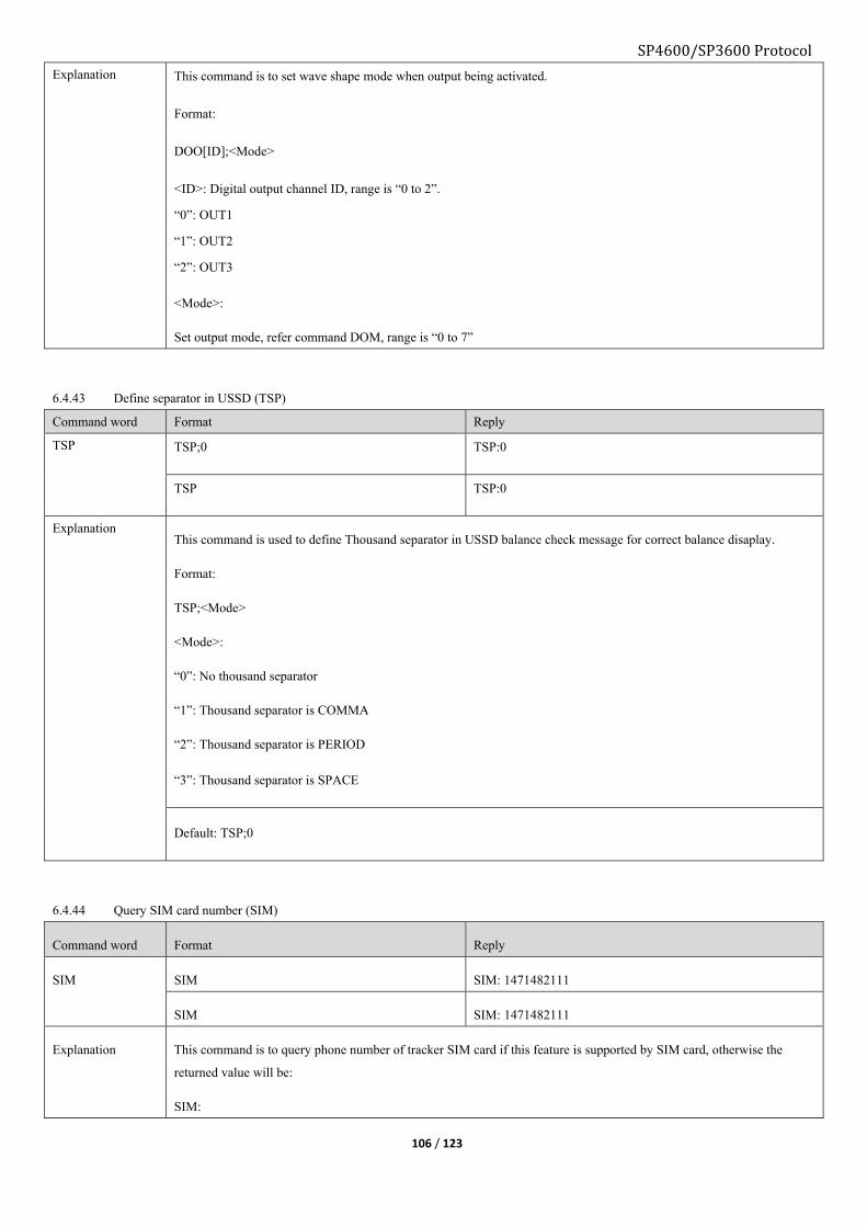
SP4600/SP3600 Protocol
106 / 123
Explanation This command is to set wave shape mode when output being activated.
Format:
DOO[ID];<Mode>
<ID>: Digital output channel ID, range is “0 to 2”.
“0”: OUT1
“1”: OUT2
“2”: OUT3
<Mode>:
Set output mode, refer command DOM, range is “0 to 7”
6.4.43 Define separator in USSD (TSP)
Command word Format Reply
TSP TSP;0 TSP:0
TSP TSP:0
Explanation This command is used to define Thousand separator in USSD balance check message for correct balance disaplay.
Format:
TSP;<Mode>
<Mode>:
“0”: No thousand separator
“1”: Thousand separator is COMMA
“2”: Thousand separator is PERIOD
“3”: Thousand separator is SPACE
Default: TSP;0
6.4.44 Query SIM card number (SIM)
Command word Format Reply
SIM SIM SIM: 1471482111
SIM SIM: 1471482111
Explanation This command is to query phone number of tracker SIM card if this feature is supported by SIM card, otherwise the
returned value will be:
SIM:

SP4600/SP3600 Protocol
107 / 123
6.4.45 Set serial link report interval by ACC (EPT)
Command word Format Reply
EPT EPT;30;3600 EPT:30;3600
EPT EPT:30;3600
Explanation This command is to set packet report interval from serial port according to ACC status.
Format:
EPT;<ACC ON interval>;<ACC OFF interval>
<ACC ON interval>: Tracker will only extract packet from its RS232 serial port periodically, e.g. <30> means when
ACC ON tracker accepts packet that from serial port every 30 seconds.
Unit is second, range is 0 – 999999, 0 means tracker will accept all packet from serial port.
<ACC OFF interval>: Tracker will only extract packet from its RS232 serial port periodically, e.g. <3600> means when
ACC OFF tracker accepts packet that from serial port every 3600 seconds.
Unit is second, range is 0 – 999999, 0 means tracker will accept all packet from serial port.
EPT;0;0
6.4.46 Hang up the ongoing call (HUP)
Command word Format Reply
HUP HUP HUP
Explanation If device receives such command it will hang up ongoing call anyway.
6.4.47 Pickup the incoming call (PUP)
Command word Format Reply
PUP PUP PUP
This command is to pick up the incoming call number that is not in the white list.

SP4600/SP3600 Protocol
108 / 123
6.4.48 Set ECALL feature (ECL)
Command word Format Reply
ECL Query current ecall phone number:
ECL;0
ECL:0
Set ecall phone number:
ECL;0;+4930367009373
ECL;0;+4930367009373
Query VIN number:
ECL;1
ECL:1;VIN10245789540124
Set VIN number: (“I”, “O”, “Q”)
ECL;1;VIN VIN10245789540124
ECL:1;VIN VIN10245789540124
Query triggered ECALL events
ECL;2
ECL:2;FF
Set events to triggered ECALL
ECL;2;FF
ECL:2;FF
ECALL events, bitwise
BIT Event name
0 Turn over
1 Collision
2 Input1
3 Input2
4 Input3
5 Input4
6 Reserved
7 Reserved
Default:
ECL;0;+4930367009373
6.4.49 Query model and version of GSM module (GVR)
Command word Format Reply
TSP GVR GVR:AGS2-W,REVISION 00.020
Explanation Format:
GVR:AGS2-W,REVISION 00.020
Model: AGS2-W
Version; REVISION 00.020
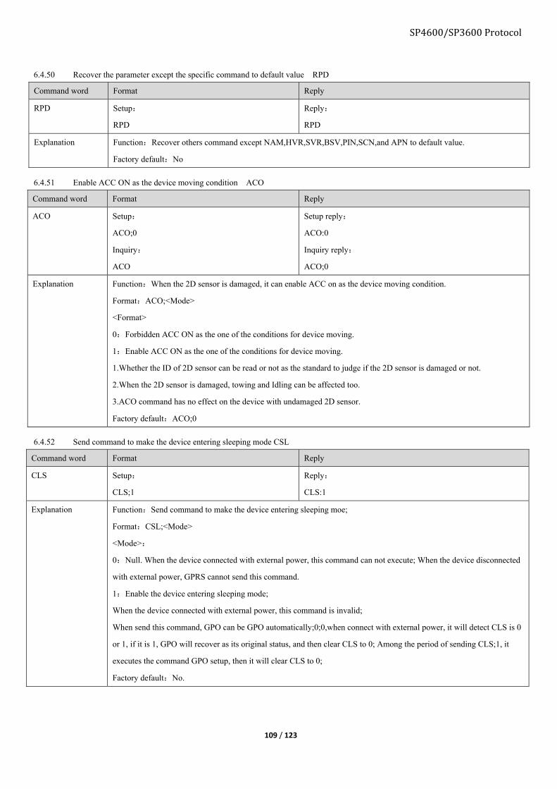
SP4600/SP3600 Protocol
109 / 123
6.4.50 Recover the parameter except the specific command to default value RPD
Command word Format Reply
RPD Setup:
RPD
Reply:
RPD
Explanation Function:Recover others command except NAM,HVR,SVR,BSV,PIN,SCN,and APN to default value.
Factory default:No
6.4.51 Enable ACC ON as the device moving condition ACO
Command word Format Reply
ACO Setup:
ACO;0
Inquiry:
ACO
Setup reply:
ACO:0
Inquiry reply:
ACO;0
Explanation Function:When the 2D sensor is damaged, it can enable ACC on as the device moving condition.
Format:ACO;<Mode>
<Format>
0:Forbidden ACC ON as the one of the conditions for device moving.
1:Enable ACC ON as the one of the conditions for device moving.
1.Whether the ID of 2D sensor can be read or not as the standard to judge if the 2D sensor is damaged or not.
2.When the 2D sensor is damaged, towing and Idling can be affected too.
3.ACO command has no effect on the device with undamaged 2D sensor.
Factory default:ACO;0
6.4.52 Send command to make the device entering sleeping mode CSL
Command word Format Reply
CLS Setup:
CLS;1
Reply:
CLS:1
Explanation Function:Send command to make the device entering sleeping moe;
Format:CSL;<Mode>
<Mode>:
0:Null. When the device connected with external power, this command can not execute; When the device disconnected
with external power, GPRS cannot send this command.
1:Enable the device entering sleeping mode;
When the device connected with external power, this command is invalid;
When send this command, GPO can be GPO automatically;0;0,when connect with external power, it will detect CLS is 0
or 1, if it is 1, GPO will recover as its original status, and then clear CLS to 0; Among the period of sending CLS;1, it
executes the command GPO setup, then it will clear CLS to 0;
Factory default:No.

110 / 123
SP4600/SP3600 Protocol
■Command over GPRS:
FWU, start firmware upgrade process: *GS06,FWU#
Confirm reply: *GS06,356496042429803,FWU#
Upgrade success reply: *GS06,356496042429803,FWU:1#
Upgrade fail reply: *GS06,356496042429803,FWU:0#
FCL, abort upgrade process: *GS06,FCL#
Confirm reply: *GS06,356496042429803,FCL:1#
Upgrade success reply: *GS06,356496042429803,FCL:0#
Upgrade fail reply: *GS06,356496042429803,FWU:0#
FRC, restore to original version: *GS06,FRC#
Confirm reply: *GS06,356496042429803,FRC:1#
Cannot execute: *GS06,356496042429803,FRC:0#
■Command over SMS:
FWU, start firmware upgrade process: 1234,FWU
Confirm reply:
G6S V2.19
FWU
EXT_PWR=0.00V
BAT=0.01V
#27
Upgrade success reply:
G6S V2.19
During over the air firmware upgrade process, it will not affect device current working status, and firmware download supports “pause and
resume”. Device receives upgrade command, it will download firmware from server over GPRS, when firmware download finished device will
reboot itself to initial upgrade process. If new firmware is faulty device will restore to original firmware automatically.
6.5. Firmware upgrade
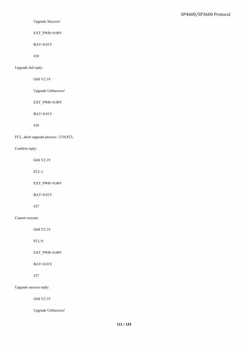
SP4600/SP3600 Protocol
111 / 123
Upgrade Success!
EXT_PWR=0.00V
BAT=0.01V
#28
Upgrade fail reply:
G6S V2.19
Upgrade UnSuccess!
EXT_PWR=0.00V
BAT=0.01V
#28
FCL, abort upgrade process: 1234,FCL
Confirm reply:
G6S V2.19
FCL:1
EXT_PWR=0.00V
BAT=0.01V
#27
Cannot execute:
G6S V2.19
FCL:0
EXT_PWR=0.00V
BAT=0.01V
#27
Upgrade success reply:
G6S V2.19
Upgrade UnSuccess!
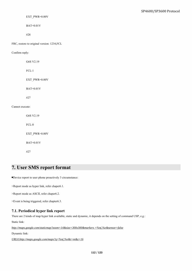
SP4600/SP3600 Protocol
112 / 123
EXT_PWR=0.00V
BAT=0.01V
#28
FRC, restore to original version: 1234,FCL
Confirm reply:
G6S V2.19
FCL:1
EXT_PWR=0.00V
BAT=0.01V
#27
Cannot execute:
G6S V2.19
FCL:0
EXT_PWR=0.00V
BAT=0.01V
#27
7. User SMS report format
■Device report to user phone proactively 3 circumstance:
>Report mode as hyper link, refer chaper6.1.
>Report mode as ASCII, refer chaper6.2.
>Event is being triggered, refer chapter6.3.
7.1. Periodical hyper link report There are 2 kinds of map hyper link available, static and dynamic, it depends on the setting of command USP, e.g.:
Static link:
http://maps.google.com/staticmap?zoom=14&size=300x300&markers =%n(,%e&sensor=false
Dynamic link:
URL0;http://maps.google.com/maps?q=%n(,%e&t=m&z=16

SP4600/SP3600 Protocol
113 / 123
GPS is fixed
Content of message Explanation
G6S V1.00
LTM 2013-06-06 14:17:12
http://maps.google.com/maps?q...
ETD:6/ACC ON
GSM -52dBm
EXT_PWR=12.08V
BAT=3.86V
#30
Device name/Firmware version
Date/Time
Google map hyper link
Event ID/User defined event name/Data
GSM network signal strength
External power voltage
Built-in battery voltage
Consumed messages
GPS is not fixed
7.2. Periodical report, Text
GPS is fixed
Content of message Explanation
G6S V1.00
LTM 2013-06-06 09:41:22
GPS 1.55/0.50/3/4
N23.164302
E113.428456
SPD:0km/h 0
GSM -52dBm
EXT_PWR=12.13V
BAT=3.96V
#27
Device name/Firmware version
Date/Time
HDOP/ALTITUDE in meter/Fixed satellite number/Time of first fixed
N means north/S means south
E means east/W means west
Speed/Heading
GSM signal strength
External power voltage
Built-in battery voltage
Consumed messages
GPS is not fixed, using LBS instead
Content of message Explanation

SP4600/SP3600 Protocol
114 / 123
G6S V1.00
LTM 2013-02-28 23:51:09
MCC/MNC/LAC/CID/RSSI
460/0/2503/962C/-53dBm
460/0/2731/40F4/-60dBm
460/0/2703/4050/-70dBm
GSM -58dB
EXT_PWR=5.13V
BAT=4.17V
#20
Device name/Firmware version
Date/Time
Base station information type
Main station, MNC/MNC/Local area code/Station ID/signal strength
Neighbor station 1
Neighbor station 2
GSM network signal strength
External power voltage
Built-in battery voltage
Consumed messages
7.3. Event SMS report If assign event is triggered, device will send notify SMS to user according to the setting.
“T” mode
1, GPS is fixed
Content of message Explanation
G6S V1.00
LTM 2013-02-28 23:51:09
GPS 1.55/0.50/3/4
N23.164302
E113.428456
SPD:0km/h 0
ETD:6/ACC ON
GSM -52dBm
EXT_PWR=12.13V
BAT=3.96V
#28
Device name/Firmware version
Date/Time
HDOP/ALTITUDE in meter/Fixed satellite number/Time of first fixed
N means north/S means south
E means east/W means west
Speed/Heading
Event ID/User defined event name/Data
GSM network signal strength
External power voltage
Built-in battery voltage
Consumed messages
2. GPS is not fixed, using LBS instead
Content of message Explanation

SP4600/SP3600 Protocol
115 / 123
G6S V1.00
LTM 2013-02-28 23:51:09
MCC/MNC/LAC/CID/RSSI
460/0/2503/962C/-53dBm
460/0/2731/40F4/-60dBm
460/0/2703/4050/-70dBm
ETD:6/ACC ON
GSM -52dBm
EXT_PWR=12.13V
BAT=3.96V
#28
Device name/Firmware version
Date/Time
Base station information type
Main station, MNC/MNC/Local area code/Station ID/signal strength
Neighbor station 1
Neighbor station 2
Event ID/User defined event name/Data
GSM network signal strength
External power voltage
Built-in battery voltage
Consumed messages
“W” mode
Content of message Explanation
G6S V1.00
LTM 2013-06-06 14:17:12
http://maps.google.com/maps?q...
ETD:6/ACC ON
GSM -52dBm
EXT_PWR=12.08V
BAT=3.86V
#301
Device name/Firmware version
Date/Time
Google map hyper link
Event ID/User defined event name/Data
GSM network signal strength
External power voltage
Built-in battery voltage
Consumed messages
8. First time usage
■Necessary command for first time usage.
8.1. Command Mode Command word Explanation
Admin
SSN Admin number (SMS server number), to set phone number as admin number
APN Set APN, for GPRS connectivity
SVR GPRS server IP and port, for GPRS server report
User UNO User number, for end user authorization
UPW User command password, change the default user command password.
9. Event listMain event Sub- Eve Event Event status Device reaction

116 / 123
event
ID
nt
ID
definitio
n
identifier 0 1 2 3 4 5 6 7
I
D
Definiti
on 0 1
I/O
port
actio
n
Repo
rt to
user
0
Repo
rt
to
user
1
Repor
t to
SMS
server
(Admi
n)
Report
to
GPRS
server
Report
to
GPRS
server
or
Admin
Reserv
ed
Reserv
ed
0 Main
event 0
0 0 Tow Tow to
normal
Normal
to tow √ √ √ √ √ √
1 1 Idle Idle to
normal
Normal
to Idle √ √ √ √ √ √
2 2 Parking Parking Quit
parking √ √ √ √ √ √
3 3 Over
speed
Over
speed to
normal
Normal
to
over
speed
√ √ √ √ √ √
4 4 GSM
jamming
GSM
jammin
g to
normal
Normal
to GSM
jamming
√ √ √ √ √ √
5 5 Geo-fenc
e Null In or out √ √ √ √ √ √
6 6
First
time
position
report
Null
First
time
position
report
√ √ √ √ √ √
7 7
Health
check
report
Null Null √ √ √ √ √
1 Main
event 1
0 8 Harsh
brake Null
Harsh
brake √ √ √ √ √ √
1 9
Harsh
accelerat
e
Null
Harsh
accelerat
e
√ √ √ √ √ √
2 10
Harsh
cornerin
g
Null
Harsh
cornerin
g
√ √ √ √ √ √
3 11 Front
collision Null
Front
collision√ √ √ √ √ √
4 12 Rear
collision Null
Rear
collision√ √ √ √ √ √
5 13 Turn
over Null
Turn
over √ √ √ √ √ √
6 14 1WIRE Temper
ature
Tempera
ture √ √ √ √ √
SP4600/SP3600 Protocol

117 / 123
inside
range/
legal
ibutton
input
outside
range
/illegal
ibutton
input
7 15 Balance
low Null Enable √ √ √ √ √ √
2 Main
event 2
0 16 External
power
Abnorm
al to
normal
Normal
to
abnorma
l
√ √ √ √ √ √
1 17 Backup
battery
Abnorm
al to
normal
Normal
to
abnorma
l
√ √ √ √ √ √
2 18 AD1
Abnorm
al to
normal
Normal
to
abnorma
l
√ √ √ √ √ √
3 19 AD2
Abnorm
al to
normal
Normal
to
abnorma
l
√ √ √ √ √ √
4 20
Entering
the
sleeping
mode
under the
situation
of
Battery
with low
voltage
Reserve
Entering
sleeping
mode
√ √ √ √ √ √
5 21 Reserved
6 22 Reserved
7 23 Reserved
3 Main
event 3
0 24 IO1 Low to
high
High to
low √ √ √ √ √ √
1 25 IO2 Low to
high
High to
low √ √ √ √ √ √
2 26 IO3 High to
low
Low to
high √ √ √ √ √ √
3 27 IO4 High to
low
Low to
high √ √ √ √ √ √
4 28 ACC ON to OFF to √ √ √ √ √ √
SP4600/SP3600 Protocol

SP4600/SP3600 Protocol
118 / 123
OFF ON
5 29 Reserved Reserve
d
Reserve
d
6 30 Reserved Reserve
d
Reserve
d
7 31 Reserved Reserve
d
Reserve
d
4 … ……Reserv
ed … …
5 … … … … …
6 … … … … …
7 Main
event 7
Comb
0 56 √ √ √ √ √ √
Comb
1 57 √ √ √ √ √ √
Comb
2 58 √ √ √ √ √ √
Comb
3 59 √ √ √ √ √ √
Comb
4 60 √ √ √ √ √ √
Comb
5 61 √ √ √ √ √ √
Comb
6 62 √ √ √ √ √ √
Comb
7 63 √ √ √ √ √ √
■Name field explanation:
Name Data type Related command Explanation
Main event ID Decimal ESM
Sub-event ID HEX ESM Sub-event mask
Event ID Decimal EUP,EOB
Reaction ID Decimal EUP Single event to trigger
APPENDIX1. OEM command and authorization
OEM command
ID Command word Explanation Default User Admin OEM
1. DFP Factory default × × √
2. OPW Set OEM password × × √
3. ACM Administrator command mask × × √
4. UCM User command mask × √ √
5. OAS Set FOTA server × √ √

SP4600/SP3600 Protocol
119 / 123
6. OAP FOTA firmware file path × √ √
7. APL APL list × √ √
8. HBI Set heartbeat packet × √ √
9. URL Set map hyper link × √ √
10. UGP Set UGP × √ √
11. CEN Enable command × √ √
12. CDS Disable command × √ √
13. SDM Sub-data report mask × √ √
14. EFM Set offline data report mode × √ √
15. ESM Sub-event mask × √ √
16. EUP Set device reaction × √ √
17. EOB Combination event parameter × √ √
18. ERL Combination event × √ √
19. ADM Main data type report mask × √ √
20. DOM Set output port mode × √ √
21. AIM Set AD/IN mode × √ √
22. DIM Digital input configuration × √ √
23. ADS Analog input configuration × √ √
24. EPS Serial port configuration × √ √
25. EPM Set serial port mode × √ √
26. BMS Harsh behavior configuration × √ √
27. AMS Accident configuration × √ √
28. UFM Set Geo-fence mask × √ √
29. AGS Set AGPS information × √ √
30. AIR Set AD1/IN3 input range × √ √
31. PKI Serial port configuration × √ √
32. PSS Power saving mode × √ √
33. GPO Toggle GSM/GPS module × √ √
34. YSF Load command list profile from computer to device × √ √
35. YGF Save command list profile from device to computer × √ √
36. YCF Load device existing command list profile × √ √
37. FRL Switching configuration profile on condition (OR) × √ √
38. DOP Output port speed condition × √ √
39. JMP GSM anti jamming configuration × √ √
40. FRS Switching configuration profile on condition (AND) × √ √
41. HOP Discard GPS position by HDOP × √ √
42. GAM Enable AT mode of GSM module × √ √
43. GAT Send AT command to GSM module × √ √
44. CTF Generate and export the current configuration file CTF × √ √
45. DOR DO OUT1 status saving start command DOR × √ √
46. SPT Set up time interval command for regularly visit
GICUS sever SPT × √ √
47. RCS GICUS sever IP/domain name, port setup command × √ √

SP4600/SP3600 Protocol
120 / 123
RCS
48. RCP GICUS sever visiting page path setup command
RCP × √ √
49 LCS Immediate visiting GICUS sever command LCS × √ √
APPENDIX2. Configuration command and authorization
Configuration command
ID Command word Explanation Default parameter User Admin OEM
1. PIN Set SIM card PIN number √ √ √
2. SCN Set SMS center number √ √ √
3. APN Set APN √ √ √
4. SVR Set main server parameter √ √ √
5. BSV Set backup sever parameter √ √ √
6. BDU Set record batch report √ √ √
7. SVP Set GPRS server report interval mode √ √ √
8. SSP Set SMS server (admin) report interval mode √ √ √
9. USP Set user report interval mode √ √ √
10. SSN Set SMS server phone number √ √ √
11. SMT Set SMS forwarding √ √ √
12. STP Configure motion sensor parameter √ √ √
13. RST Reboot device √ √ √
14. TZN Set time zone √ √ √
15. DST Configure daylight saving parameter √ √ √
16. STO Set daylight saving √ √ √
17. PTH Power supply alarm √ √ √
18. DNU Set Report interval mode switching condition √ √ √
19. DIS Fixed distance report and cornering report √ √ √
20. ATH Analog input event condition √ √ √
21. VOE Voice functionality configuration √ √ √
22. PWL Phone number white list √ √ √
23. QWL Query position permitted phone number white list √ √ √
24. MWL Stealthy voice monitoring white list √ √ √
25. HWL Hot line number white list √ √ √
26. SWL SOS phone number white list √ √ √
27. GFS Geo-fence status √ √ √
28. GOF Set Geo-fence √ √ √
29. BMO Set driving behavior detection √ √ √
30. AMO Set accident detection √ √ √
31. BDS Set device installation direction √ √ √
32. MGE Set odometer counter √ √ √
33. MGS Set odometer initial mileage √ √ √
34. SPO Set Over speed report condition √ √ √
35. SPS Over speed configuration √ √ √
36. ILO Set Idle status detection √ √ √

SP4600/SP3600 Protocol
121 / 123
37. ILS Idle status configuration √ √ √
38. ETO Set engine hour counter √ √ √
39. ETS Engine initial hour counter value √ √ √
40. HTM Device healthy check report √ √ √
41. AGP Set Assist GPS √ √ √
42. SCF Save current configuration as profile to device √ √ √
43. RCF Load configuration profile √ √ √
44. PVM Private hour mode configuration √ √ √
45. POB Private hour mode output mode configuration √ √ √
46. IBO Set 1-WIRE working mode √ √ √
47. IBI Set iButton permit list √ √ √
48. IBP Set iButton working mode √ √ √
49. TMP Set 1-WIRE temperature alarm range √ √ √
50. SVT Server timeout configuration √ √ √
51. IBE Set ibutton key special mode √ √ √
52. IBS Define ibutton key special mode √ √ √
53. ITS Input event to activate serial port output √ √ √
54. SUR Set USSD server √ √ √
55. SUP USSD server report interval mode √ √ √
APPENDIX3. Public command and authorization
Public command
ID Command word Explanation Default parameter User Admin OEM
1. UNO Set user phone number √ √ √
2. UPW Set user command password √ √ √
3. MOT Configure motion sensor parameter √ √ √
4. USC Set user short command √ √ √
5. FWU Upgrade command √ √ √
6. FCL Abort the ongoing FOTA process √ √ √
7. FRC Reverse to previous version √ √ √
8. AGN Set audio parameter √ √ √
9. CAL Set device dial-back phone number √ √ √
10. ENM Rename event for user SMS √ √ √
11. ETC Clear event status √ √ √
12. ERT Query engine running time √ √ √
13. FPD Query output port type and data √ √ √
14. PRQ Query current position √ √ √
15. TIM Query current GMT time √ √ √
16. NAM Query product name √ √ √
17. VER Query device hardware/software version √ √ √
18. MEI Query IMEI number √ √ √
19. MSI Query IMSI of SIM card √ √ √
20. CID Query CCID of SIM card √ √ √
21. CSQ Query GSM signal strength √ √ √

SP4600/SP3600 Protocol
122 / 123
22. REG Query GSM registration status √ √ √
23. SCC Clear SMS counter √ √ √
24. SCR Query SMS counter √ √ √
25. GSM Query GSM information √ √ √
26. GPS Query GPS information √ √ √
27. ADC Query ADC information √ √ √
28. GFT Query GFT information √ √ √
29. STT Query device status √ √ √
30. GTT Query Geo-fence status √ √ √
31. MGR Query mileage √ √ √
32. ETT Query event status bit √ √ √
33. JAM Enable anti-jamming feature √ √ √
34. TOW Enable Tow detection feature √ √ √
35. CFN Query current configuration profile number √ √ √
36. PTY Query device model √ √ √
37. CHC Query licensed status √ √ √
38. IBC Reset iButton ID √ √ √
39. GFC Reset Geo fence √ √ √
40. EUC Reset all events action √ √ √
41. BLS Balance notification √ √ √
42. DOO Digital output specify wave shape √ √ √
43. TSP Define separator in USSD √ √ √
44. SIM Query current SIM phone number √ √ √
45. EPT Set serial port report interval by ACC √ √ √
46. HUP Hang up the ongoing call √ √ √
47. PUP Pick up the incoming call √ √ √
48. ECL Set ECALL feature √ √ √
49. GVR Query model and version of GSM module √ √ √
50. RPD Recover the parameter except the specific command
to default value √ √ √
51. ACO Enable ACC ON as the device moving condition √ √ √
52. CSL Send command to make the device entering sleeping
mode √ √ √
APPENDIX4. Device LED Behavior
GSM LED: Green GPS LED: Yellow Power LED: Red

SP4600/SP3600 Protocol
123 / 123
Socket connected:
Flash once
GSM registered:
Flash 2 times
GSM unregistered:
Flash 3 times
SIM card error:
Flash 4 times
Serial port communication error: Flash 5
times
GSM module OFF:
LED off
GPS fixed:
Flash once
GPS unfixed:
Flash 2 times
GPS communication error:
Flash 3 times
GPS module OFF:
LED off
External power supply:
Flash once
Backup battery power supply:
Flash 2 times
Backup battery low voltage:
Flash 3 times
Under iButton ID config mode:
Keep glowing
iButton ID config successfully:
Flashing once per second
e.g.: GPS fixed, GPS LED will flash once, and wait for 3 seconds to flash once more.