galaxy iv traction elevator controller manual
TRANSCRIPT

i
GALaxy IV Traction
Elevator Controller Manual
GAL Manufacturing Corporation LLC 50 East 153rd Street Bronx, NY 10451 Technical Support: 1‐877‐425‐7778

ii
Foreword
GAL Manufacturing has developed this manual with usability and safety in mind. General and specific safety notices and precautions are defined in the manual. However, GAL Manufacturing cannot be responsible for any injury to persons or damage to property (including the elevator equipment) resulting from negligence, misuse of the equipment, misinterpretation of instructions included in this manual, or due to any other cause beyond the control of GAL Manufacturing.
All drawings, illustrations, and information herein are the property of GAL Manufacturing and must not be made public or reproduced by any individual or entity other than the purchaser hereof without the express written permission of GAL Manufacturing.
Revision 8.6 GAL Part Number: DOC4-0002N

iii
Table of Contents
GALaxy IV Traction Elevator Controller Manual ............................................................................................... i Foreword .................................................................................................................................................................... ii Table of Contents ..................................................................................................................................................... iii Section 1 - Product Description ........................................................................................................................ 1-1
1.1 Product Code Compliance ........................................................................................................................ 1-1 1.2 Specifications ............................................................................................................................................ 1-1 1.3 Physical Layout of the Controller ............................................................................................................... 1-1
1.3.1 Controller Top Cabinet ..................................................................................................................... 1-3 1.3.2 Controller Bottom Cabinet ................................................................................................................ 1-5
1.4 Selector System ........................................................................................................................................ 1-6 1.4.1 Tapeless Selector System ................................................................................................................ 1-6 1.4.2 Absolute Position System (APS) Selector ........................................................................................ 1-8 1.4.3 Primary and Secondary Speed Feedback ........................................................................................ 1-9
1.5 Modes of Operation ................................................................................................................................... 1-9 1.5.1 General Operating Sequence ........................................................................................................... 1-9 1.5.2 Reset Mode .................................................................................................................................... 1-10 1.5.3 Safety String Open Mode ............................................................................................................... 1-10 1.5.4 Controller Inspection Mode ............................................................................................................. 1-11 1.5.5 Car Top Inspection Mode ............................................................................................................... 1-11 1.5.6 Access Mode .................................................................................................................................. 1-11 1.5.7 Independent Service Mode ............................................................................................................. 1-11 1.5.8 Load Weighing Bypass Mode ......................................................................................................... 1-12 1.5.9 Attendant Service Mode ................................................................................................................. 1-12 1.5.10 Code Blue Hospital Service Mode .................................................................................................. 1-12 1.5.11 Fire Service Phase I Mode ............................................................................................................. 1-12 1.5.12 Fire Service Phase I Alternate Return Mode .................................................................................. 1-13 1.5.13 Fire Service Phase II Mode ............................................................................................................ 1-13 1.5.14 Emergency Power Mode ................................................................................................................ 1-14 1.5.15 Earthquake Mode ........................................................................................................................... 1-14 1.5.16 Stalled Mode .................................................................................................................................. 1-14 1.5.17 Automatic Mode.............................................................................................................................. 1-14
Section 2 - Installation ...................................................................................................................................... 2-1
2.1 General Information .................................................................................................................................. 2-1 2.2 Selection of an Installation Site ................................................................................................................. 2-1 2.3 Environmental Considerations for Installation ........................................................................................... 2-1 2.4 Wiring Guidelines and Instructions ............................................................................................................ 2-2
2.4.1 Wiring Schematics ................................................................................................................................ 2-2 2.4.2 Proper Field Wiring ............................................................................................................................... 2-2 2.4.3 Ground Wiring ....................................................................................................................................... 2-2 2.4.4 Hoistway Wiring .................................................................................................................................... 2-2 2.4.5 Elevator Car Wiring ............................................................................................................................... 2-3 2.4.6 Machine Room Wiring ........................................................................................................................... 2-3
2.5 Requirements for a Running Platform During Initial Startup ...................................................................... 2-3 2.6 Normal and Emergency Terminal Slowdown Limits .................................................................................. 2-3
2.6.1 Normal Terminal Slowdown Limits ........................................................................................................ 2-3 2.6.2 Emergency Terminal Slowdown Limits ................................................................................................. 2-3
2.7 Directional Limit Switches ......................................................................................................................... 2-4 2.8 Final Limit Switches .................................................................................................................................. 2-5 2.9 Selector Installation ................................................................................................................................... 2-5
2.9.1 APS (Absolute Position System) Selector Installation........................................................................... 2-5

iv
2.9.1.1 Installation of the Encoded Tape .................................................................................................. 2-5 2.9.1.2 APS Selector Floor Position Setup (Hoistway Learn) ................................................................. 2-16 2.9.1.3 Verify that the APS Selector is Installed Correctly and Communicating ..................................... 2-16 2.9.1.4 Setting the APS Adjustable Variables ........................................................................................ 2-16 2.9.1.5 Zero the Hoistway ...................................................................................................................... 2-16 2.9.1.6 Setting Hoistway Floor Levels with APS Selector ...................................................................... 2-18
2.9.2 Tapeless Selector Installation ............................................................................................................. 2-20 2.9.2.1 Tapeless Selector 7 ................................................................................................................... 2-20 2.9.2.2 Tapeless Selector 5 ................................................................................................................... 2-26
Section 3 - GALaxy Adjustment ..................................................................................................................... 3-1
3.1 Procedure for Initial Power-up of Controller .............................................................................................. 3-1 3.1.1 Checking Main Line Voltage ................................................................................................................. 3-1 3.1.2 Checking Controller Voltages ............................................................................................................... 3-1 3.1.3 Verifying Operation of the Main CPU .................................................................................................... 3-1
3.2 Start-up Procedures .................................................................................................................................. 3-2 3.2.1 Requirements for a running platform during initial startup ..................................................................... 3-2 3.2.2 Check Inspection Speed ....................................................................................................................... 3-9 3.2.3 Complete the Installation of Equipment ................................................................................................ 3-9
3.3 Adjustment Procedures ............................................................................................................................. 3-9 3.3.1 Verify Inspection Operation ................................................................................................................. 3-10 3.3.2 Verify the Main CPU Velocity Feedback ............................................................................................. 3-11 3.3.3 Verify the Encoder Direction for the Main CPU ................................................................................... 3-11 3.3.4 Match Feedback Velocity and Direction .............................................................................................. 3-11 3.3.5 Verify Safety Processor Velocity and Direction Feedback .................................................................. 3-12 3.3.6 Verify NTS Processor Velocity and Direction Feedback ..................................................................... 3-12 3.3.7 Hoistway Learn Procedure .................................................................................................................. 3-12 3.3.8 Adjust the Elevator .............................................................................................................................. 3-14
3.3.8.1 Automatic Run............................................................................................................................ 3-14 3.3.8.2 Fine Tune the Ride Quality ........................................................................................................ 3-14 3.3.8.3 Adjust the Stop ........................................................................................................................... 3-16 3.3.8.4 Adjust the Start........................................................................................................................... 3-17 3.3.8.5 Load Weigher Setup .................................................................................................................. 3-17 3.3.8.6 Empty Car Setup for Load Weigher ........................................................................................... 3-18 3.3.8.7 Full Load Setup for Load Weigher .............................................................................................. 3-18 3.3.8.8 Load Weigher Calibration Sequence .......................................................................................... 3-18 3.3.8.9 Adjust Load Weigher Pretorque ................................................................................................. 3-19 3.3.8.10 Adjust Synthetic Pretorque ......................................................................................................... 3-20
3.3.9 Adjust Safety Processor, NTS Processor, and Main CPU Limit Velocity Speed Clamps .................... 3-21 3.3.9.1 Learn the Safety Processor, NTS Processor, and Main CPU Limit Velocity Speed Clamps ...... 3-22 3.3.9.2 Manually Adjust the Safety Processor and NTS Processor Limit Velocity Speed Clamps ......... 3-23 3.3.9.3 Manually Adjust the Main CPU’s Limit Velocity Speed Clamps ................................................. 3-23 3.3.9.4 Verify Inspection Velocity Clamp on Safety Processor ............................................................... 3-24
3.3.10 Reduced Stroke Buffer ETS Limits Setup ....................................................................................... 3-24 3.3.10.1 Manual Setup of ETS Limit Velocities ........................................................................................ 3-25
3.3.11 Verify Proper Operation of All Safety Circuits and Signal Devices ................................................. 3-25 3.3.12 Perform Required Tests ..................................................................................................................... 3-26
Section 4 - Troubleshooting ............................................................................................................................ 4-1
4.1 General Information ................................................................................................................................... 4-1
4.2 Microprocessor CPU ................................................................................................................................. 4-1 4.3 Input / Output Boards................................................................................................................................. 4-1 4.4 Run Sequence ........................................................................................................................................... 4-2 4.5 The Safety Processor and Safety PAL ....................................................................................................... 4-2
4.5.1 The CPU outputs that are controlled by the Safety PAL ........................................................................ 4-3 4.5.2 The inputs monitored by the Safety Processor and Safety PAL ............................................................. 4-3 4.5.3 Outputs controlled by the Safety Processor ........................................................................................... 4-3

v
4.5.4 PIC and PAL Inhibit LEDs ..................................................................................................................... 4-5 4.5.5 MCU and COM LEDs ............................................................................................................................ 4-6 4.5.6 Troubleshooting Safety Processor and Safety PAL Faults .................................................................... 4-6
4.6 Fault Log ................................................................................................................................................... 4-6 4.7 Main CPU Inputs and Outputs ................................................................................................................... 4-7 4.8 Safety Processor Inputs and Outputs ...................................................................................................... 4-15 4.9 NTS Processor Inputs and Outputs ......................................................................................................... 4-16 4.11 APS Selector Inputs and Outputs ............................................................................................................ 4-17
4.12 Relocate I/Os ........................................................................................................................................... 4-18 4.13 GALileo Enhanced Diagnostics ............................................................................................................... 4-18
4.13.1 GALileo Trace Screen ..................................................................................................................... 4-19 Section 5 – LCD Interface ................................................................................................................................. 5-1
5.1 Operating the LCD Interface ...................................................................................................................... 5-1 5.1.1 Interface Operator Panel ....................................................................................................................... 5-1 5.1.2 LCD Interface Main Menu ..................................................................................................................... 5-2 5.1.3 Elevator Status ...................................................................................................................................... 5-2 5.1.4 Set Calls and Lockouts .......................................................................................................................... 5-3 5.1.5 Car Call Test ......................................................................................................................................... 5-3 5.1.6 Inputs & Outputs ................................................................................................................................... 5-4 5.1.7 Job Statistics ......................................................................................................................................... 5-4 5.1.8 Adjustable Variables .............................................................................................................................. 5-4 5.1.9 Car Timers ............................................................................................................................................ 5-4 5.1.10 Date and Time .................................................................................................................................. 5-4 5.1.11 Diagnostics ....................................................................................................................................... 5-5 5.1.12 Software Utilities ............................................................................................................................... 5-5 5.1.13 Power-Up Mode ................................................................................................................................ 5-6 5.1.14 Update / Verify Program ................................................................................................................... 5-6 5.1.15 Select Video Display ......................................................................................................................... 5-6 5.1.16 Service Activation Timers.................................................................................................................. 5-6 5.1.17 Display Hoistway Table ..................................................................................................................... 5-7 5.1.18 DZ & DZ Offset, Sel Cnt .................................................................................................................... 5-7 5.1.19 FL & FL Offset Count ........................................................................................................................ 5-7 5.1.20 Reset Update Count Trig, Pulse Count Update Data ........................................................................ 5-7 5.1.21 Elevator Setup .................................................................................................................................. 5-7 5.1.22 Match Feedback Velocity & Direction ................................................................................................ 5-7 5.1.23 Auto Learn Hoistway ......................................................................................................................... 5-8 5.1.24 Inspection Learn Hoistway ................................................................................................................ 5-8 5.1.25 Learn Limit Velocities ........................................................................................................................ 5-8 5.1.26 Manually Setting Main CPU Speed Clamps ...................................................................................... 5-8 5.1.27 Inspection Open – Close Door .......................................................................................................... 5-8 5.1.28 Lift Brake on Inspection .................................................................................................................... 5-8 5.1.29 Loadweigher Setup ........................................................................................................................... 5-8 5.1.30 Load Weigher View/Modify ............................................................................................................... 5-8 5.1.31 Calibrate Load Weigher .................................................................................................................... 5-9 5.1.32 Counterweight & Buffer Test ............................................................................................................. 5-9 5.1.33 Overspeed Test ................................................................................................................................ 5-9 5.1.34 Reset / View Faults ........................................................................................................................... 5-9 5.1.35 View Fault Log .................................................................................................................................. 5-9 5.1.36 Clear Fault Log ................................................................................................................................. 5-9 5.1.37 Reset Gripper Menu.......................................................................................................................... 5-9
5.2 LCD Menu Diagrams ............................................................................................................................... 5-10 5.2.1 Main Menu .......................................................................................................................................... 5-10 5.2.2 Elevator Status .................................................................................................................................... 5-11 5.2.3 Set Calls and Lockouts ........................................................................................................................ 5-14 5.2.4 Car Call Test ....................................................................................................................................... 5-15 5.2.5 Lockout Front Car Calls ....................................................................................................................... 5-16

vi
5.2.7 Relocate I/Os ...................................................................................................................................... 5-18 5.2.8 Add I/O Relocation .............................................................................................................................. 5-19 5.2.9 Job Statistics ....................................................................................................................................... 5-20 5.2.10 Adjustable Variables ....................................................................................................................... 5-21 5.2.11 Car Timers ...................................................................................................................................... 5-22 5.2.12 Date and Time ................................................................................................................................ 5-23 5.2.13 Diagnostics ..................................................................................................................................... 5-24 5.2.14 View System Status Log ................................................................................................................. 5-25 5.2.15 Group Comm Status ....................................................................................................................... 5-26 5.2.16 Group Can Comm Status ................................................................................................................ 5-27 5.2.17 Car Can Comm Status .................................................................................................................... 5-28 5.2.18 Machine Room Can Comm Status .................................................................................................. 5-29 5.2.19 Safety Can Comm Status ............................................................................................................... 5-30 5.2.20 Drive Comm Status ......................................................................................................................... 5-31 5.2.21 APS CAN Comm Status ................................................................................................................. 5-32 5.2.22 Software Utilities ............................................................................................................................. 5-33 5.2.23 Power-Up Mode .............................................................................................................................. 5-34 5.2.24 Power-Up Mode –> Update / Verify Program .................................................................................. 5-35 5.2.25 SD Card Read / Write Data ............................................................................................................. 5-36 5.2.26 Network Card Setup........................................................................................................................ 5-37 5.2.27 Preset Limit Velocities ..................................................................................................................... 5-38 5.2.28 Trace Setup .................................................................................................................................... 5-39 5.2.29 Send Floor Table to APS ................................................................................................................ 5-40 5.2.30 Select Video Display ....................................................................................................................... 5-41 5.2.31 Service Activation Timer ................................................................................................................. 5-42 5.2.32 Set Month/Day Timers .................................................................................................................... 5-43 5.2.33 Clear Timers ................................................................................................................................... 5-44 5.2.34 Copy Day of Week Timers .............................................................................................................. 5-45 5.2.35 View / Modify Timer Status ............................................................................................................. 5-46 5.2.36 Set Timer Service ........................................................................................................................... 5-47 5.2.37 Set Day of Week Timers ................................................................................................................. 5-48 5.2.38 Display/Modify Hoistway Tables...................................................................................................... 5-49 5.2.39 DZ & DZ Offset, Selector Count ...................................................................................................... 5-50 5.2.40 FL & FL Offset Count ...................................................................................................................... 5-51 5.2.41 Reset Update Count, Pulse Count Update ...................................................................................... 5-52 5.2.42 Elevator Setup ................................................................................................................................ 5-53 5.2.43 Match Feedback Velocity & Direction .............................................................................................. 5-54 5.2.44 Learn Hoistway ............................................................................................................................... 5-55 5.2.45 Learn Limit Velocities ...................................................................................................................... 5-58 5.2.46 Open / Close Door .......................................................................................................................... 5-59 5.2.47 Lift Brake On Inspection .................................................................................................................. 5-60 5.2.48 Load Weigher Setup ....................................................................................................................... 5-61 5.2.49 Car Buffer Test ............................................................................................................................... 5-64 5.2.50 Overspeed Test .............................................................................................................................. 5-65 5.2.51 Reset / View Faults ......................................................................................................................... 5-66 5.2.52 Reset Gripper / EBK Fault............................................................................................................... 5-67
Section 6 – System Faults & Detailed Faults .............................................................................................. 6-1
6.1 System Faults ........................................................................................................................................... 6-1 6.2 Detailed Faults Data and Description .................................................................................................... 6-132
6.2.1 Detailed Fault I/O Data Example....................................................................................................... 6-152 6.2.2 Detailed Fault I/O Data Form ............................................................................................................ 6-155
6.3 KEB Inverter Status DG02 Table .......................................................................................................... 6-165
vii
Section 7 – Adjustable Variables ........................................................................................................... 7-1
7.1 Main CPU Adjustable Variables ........................................................................................................ 7-1 7.1.1 Car Motion Submenu .................................................................................................................... 7-1
7.1.2 Car Brake Submenu ..................................................................................................................... 7-6 7.1.3 Modified Motion Submenu .......................................................................................................... 7-10 7.1.4 Car Timers Submenu .................................................................................................................. 7-12 7.1.5 Car Options Submenu ................................................................................................................ 7-17 7.1.6 Service Options Submenu .......................................................................................................... 7-25 7.1.7 Emergency Services Submenu ................................................................................................... 7-32 7.1.8 Group Dispatch Submenu........................................................................................................... 7-37 7.1.9 Group Options Submenu ............................................................................................................ 7-42 7.1.10 CC & COP Lights Submenu ................................................................................................... 7-51 7.1.11 HC & IR Call Lights Submenu ................................................................................................ 7-59 7.1.12 CB, VIP HSec Hall Lights Submenu ....................................................................................... 7-67 7.1.13 System Options Submenu ...................................................................................................... 7-72
7.2 Safety Processor Adjustable Variables ........................................................................................... 7-78 7.3 NTS Processor Adjustable Variables .............................................................................................. 7-82
7.4 APS Selector Adjustable Variables ................................................................................................. 7-86 Section 8 – Appendix A ........................................................................................................................................ 8-1
8.1 Testing Precheck ....................................................................................................................................... 8-1 8.2 Inertia Learn (KEB Drive) ........................................................................................................................... 8-2 8.3 Learn Limit Velocities................................................................................................................................. 8-2 8.4 Emergency Terminal Speed Limiting Device ............................................................................................. 8-2
8.4.1 Testing ETSLD At The Bottom Terminal Landing .................................................................................. 8-2 8.4.2 Testing ETSLD At The Top Terminal Landing ....................................................................................... 8-3
8.5 Emergency Terminal Stopping device ....................................................................................................... 8-4 8.5.1 Testing ETSD At The Bottom Terminal Landing .................................................................................... 8-4 8.5.2 Testing ETSD At The Top Terminal Landing ......................................................................................... 8-4
8.6 NTSD – Normal Terminal Stopping Device ................................................................................................ 8-5 8.6.1 Test The Top and Bottom Normal Limits ............................................................................................... 8-5 8.6.2 Testing NTSD At The Bottom Terminal Landing .................................................................................... 8-5 8.6.3 Testing NTSD At The Top Terminal Landing ......................................................................................... 8-5
8.7 Ascending Car Overspeed ......................................................................................................................... 8-6 8.7.1 Test Ascending Car Overspeed From Governor Switch ........................................................................ 8-6 8.7.2 Test Ascending Car Overspeed Stopping With Emergency Brake Only ................................................ 8-7 8.7.3 Test Ascending Car Overspeed Detection From Main Processor .......................................................... 8-8
8.8 Unintended Movement .............................................................................................................................. 8-8 8.8.1 Test Unintended Motion ........................................................................................................................ 8-8
8.9 Speed Control on Inspection...................................................................................................................... 8-9
8.9.1 Check Inspection Speed Limit ............................................................................................................... 8-9 8.10 Speed Control on Access .......................................................................................................................... 8-9
8.10.1 Test Access Speed Limit .................................................................................................................. 8-9 8.11 Speed in Leveling / Truck Zone ................................................................................................................. 8-9
8.11.1 Test Leveling Speed Limit ................................................................................................................. 8-9 8.12 Inner Landing Zone Limits ....................................................................................................................... 8-10
8.12.1 Test Inner Landing Zone Limits ....................................................................................................... 8-10 8.13 Protection Against Traction Loss ............................................................................................................. 8-10
8.13.1 Test Protection Against Traction Loss ............................................................................................. 8-11 8.14 Emergency Power ................................................................................................................................... 8-11
8.14.1 Test Emergency Power ................................................................................................................... 8-11 8.14.2 Power Loss Brake Lift ..................................................................................................................... 8-11 8.14.3 Test MBC Contactor ....................................................................................................................... 8-11 8.14.4 Testing The Communication From The Controller To The UPS ...................................................... 8-12 8.14.5 Testing The UPS Battery Capacity .................................................................................................. 8-12 8.14.6 Procedure To Electrically Pick The Main And Emergency Brake .................................................... 8-12

viii
SYMBOLS USED IN THIS MANUAL
CAUTION
This manual uses the CAUTION symbol to identify procedures and practices that may result in personal injury and/or equipment damage, if not followed correctly.
DANGER
This manual uses the DANGER symbol as an alert to a danger of electrocution or an acute electrical shock. The DANGER symbol provides elevator personnel with a warning of severe personal injury or potential fatality that can result if safety precautions are not observed.
NOTE / INFORMATION
In this manual, this symbol identifies information helpful to elevator personnel when carrying out a specific procedure or task.
NOT APPLICABLE / DOES NOT EXIST
When this symbol appears inside a table, it indicates that a value or property is not defined, or is nonexistent, for the item listed.

ix
WARNINGS AND CAUTIONARY NOTES
Installation and wiring must be in accordance with the national electrical code, all local codes, and all elevator safety codes and standards. The 3‐phase AC power supply to the equipment must originate from a properly fused disconnect or circuit breaker that is properly designed and sized for the specific controller requirements and the “Short Circuit Current Rating” listed on the controller. Improper motor branch circuit protection will void warranty and may create a hazardous condition.
Wiring to the controller terminals must be installed in a careful, neat manner. Stranded wire conductors must not have strands left out of the terminals. Leaving strands of wire out of the terminals can create a potential short circuit. All terminals and cable connectors must be seated properly. (See the IMPORTANT notice on the next page.)
Elevator control products must be installed by elevator personnel who have been trained in the construction, maintenance, repair, inspection, and testing of elevator equipment. The elevator personnel must comply with all applicable safety codes and standards. This equipment is an O. E. M. product designed and manufactured to comply with ASME A17.1-2016/CSA B44-16 Safety Code for Elevators and Escalators. It is the responsibility of the installer to ensure that the installation is performed safely and that the installation complies with all applicable codes.
Proper grounding is vitally important to the safe and successful operation of this system, and proper grounding should be installed to comply with all applicable codes. A separate ground wire should be installed from the building earth ground to the earth ground terminal in each controller. Proper conductor size must be utilized for grounding. In order to minimize resistance to ground, the shortest possible length should be used for the ground conductor.
Do not install the controller in a hazardous area where excessive vapors and chemical fumes are present. Do not install the controller in a dusty area. Do not install the controller in a carpeted area. The space in which the controller equipment is installed should be temperature controlled, moisture free, and should be maintained within a temperature range of 32° F and 110°F. The space in which the controller equipment is installed should be kept clean. The controller should be kept dry and should not be exposed to moisture or water condensation. Make sure the power supply voltage feeding the controller equipment does not fluctuate by more than +/- 10%.
Every safety precaution, whether or not specifically stated in this document, must be implemented when installing, adjusting, or servicing elevator equipment. All safety precautions must be followed to ensure the safety of elevator personnel and the general public.
Use only the correct rated fusing for controller protection. Use of improperly rated fusing will void the warranty.

x
IMPORTANT NOTICE
Most of the field connections to GALaxy controls are made using stranded wire. When inserting this stranded wire into the terminals – especially those for EPD’s (Electrical Protective Devices) – care must be taken to ensure that all the strands are properly inserted into the terminals. Improper stripping and insertion may leave strands outside of the terminals. Strands not properly inserted into the terminals may make contact with wires from an adjacent terminal.
The danger associated with an occurrence as described above has led GAL Manufacturing to recommend that, for all connections to the Electrical Protective Devices listed in ASME A17.1-2016/CSA B44-16, Requirements 2.26.2.1 through 2.26.2.39, elevator personnel must follow the guidelines listed below:
• Inspect all terminals used to connect Electrical Protective Devices. Ensure that the cage clamp is fully open before inserting a wire into the terminal block.
• Perform corrective action for wires with stray strands by one of the following methods: o Reconnect the wire with all wire strands correctly installed into the terminal. Visually verify that
no wire strands are outside of the terminal. The conductor should be stripped and inserted completely into the terminal in such a manner that no more than two millimeters of bare wire is visible; or
o Attach a ferrule to the end of field wire for safety devices (as pictured below in Figures 0-1 and 0-2) and insert the ferrule into the terminal; or
o Use an acceptable method such as tinning. • After removal and replacement of any of these field wires, the actual Electrical Protective Device
should be checked for proper operation.
Figure 0-1 Crimp Tool for Ferrule
Figure 0-2 Stranded Wire with Ferrule
Attached
GALaxy IV Traction Elevator Controller Section 1 – Product Description
1-1
Section 1 - Product Description
The GALaxy IV Traction Elevator Controller is a computer-based system offering superior performance, flexibility, and reliability. The controller is designed for quick installation and ease of troubleshooting. It is extremely important for elevator personnel to become familiar with the procedures in this manual. The manual provides a detailed reference for controller installation, and elevator personnel should read it thoroughly before attempting to install the equipment.
1.1 Product Code Compliance • CSA B44.1-14/ASME A17.5-2014
• ASME A17.1-2016/CSA B44-16
1.2 Specifications
Standard Features: Environment: • Inspection Operation (Car Top & Controller)
• •
• 32°F to 110°F Ambient Temperature
• Access Operation • 12,000 Feet Maximum Altitude
• Independent Service • 95% Maximum Humidity
• Fire Service Phase I
• Fire Service Phase I Alternate Return
• Fire Service Phase II Optional Features:
• Emergency Power • Selective Rear Doors
• Earthquake Service • Attendant Service
• Onboard Diagnostics LEDs • Code Blue Hospital Service
• Onboard LCD Interface • Security
• Motor Protection Timers • Remote Diagnostics
• Door Motor Protection Timer • Emergency Power
• Field Adjustable Parameters
• Elevator Duty Rated NEMA Motor
• GALileo Enhanced Diagnostics • e
e
a
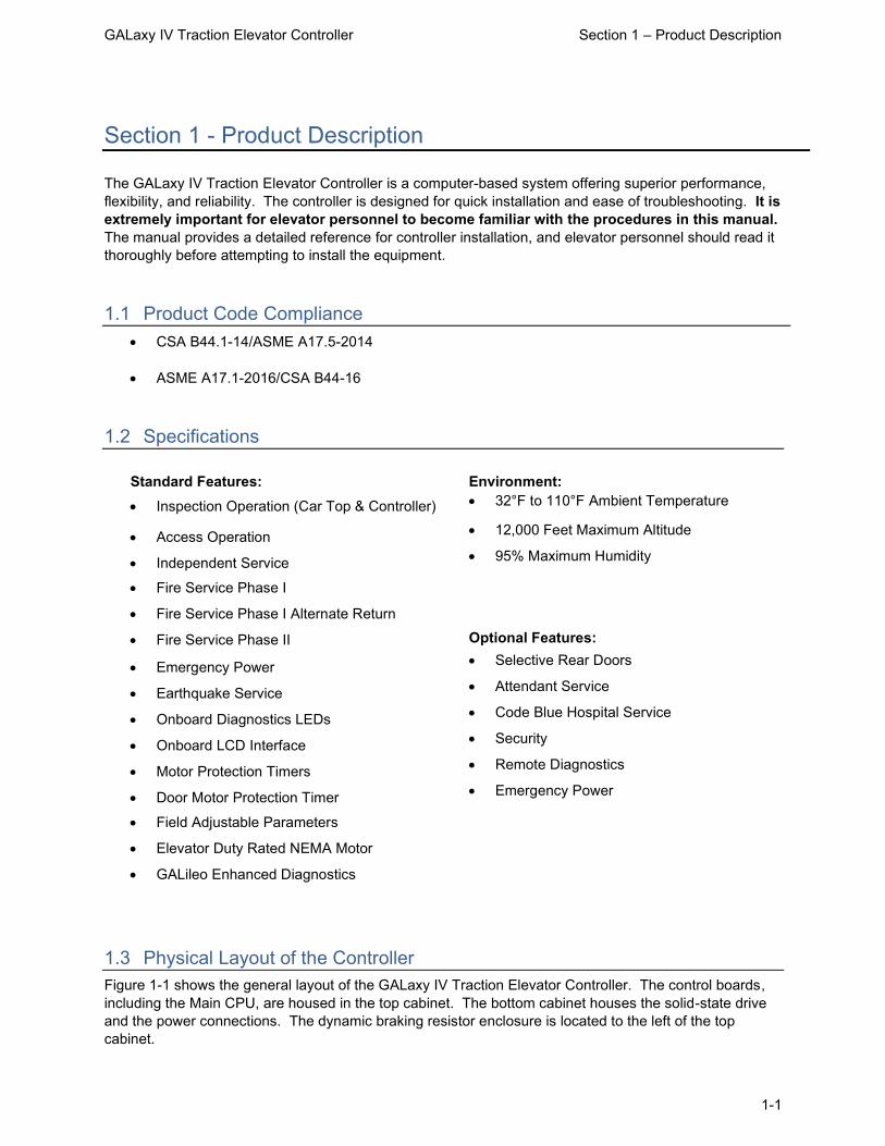
1.3 Physical Layout of the Controller Figure 1-1 shows the general layout of the GALaxy IV Traction Elevator Controller. The control boards, including the Main CPU, are housed in the top cabinet. The bottom cabinet houses the solid-state drive and the power connections. The dynamic braking resistor enclosure is located to the left of the top cabinet.

GALaxy IV Traction Elevator Controller Section 1 – Product Description
1-2
Figure 1-1: General Layout of the Controller

GALaxy IV Traction Elevator Controller Section 1 – Product Description
1-3
1.3.1 Controller Top Cabinet Figure 1-2 shows a typical layout of the components inside the top cabinet. These components are listed below.
1) Main I/O Board: The 1102 Main Control Board contains input and output devices, controller switches, fuses and field wiring terminal connections. The Main I/O Board also includes the Safety Processor, the Safety PAL, and the NTS Processor.
2) Main CPU Board: The 1100 CPU Board is a dual core 32-bit CPU. It executes the main control system programs. The main core runs the car operation and the secondary core runs the group operation.
3) LCD Interface: The 1005 LCD Interface Board or the 1101 LCD/VGA Interface Board provides a user interface to all controller adjustments, adjustable parameters, and diagnostic information.
4) Power Supply Board: This board provides power to the controller CPU and its peripheral boards. It is a 5 Volt DC regulated power supply rated at 6 Amps with over-voltage and short circuit protection.
5) PI Driver Board: This board is the driver for CE or E-Motive Position Indicator Displays.
6) Main Brake Power Board: This board provides DC power for the Main Brake Relay Board.
7) Main Brake Relay Board: This board includes the Run and the Brake contactors which provide two electro-mechanical devices to remove power from the main brake.
8) Emergency Brake Relay Board: This board includes the Run and the Brake contactors which provide two electro-mechanical devices to remove power from the emergency brake.
9) Emergency Brake Power Board: This board provides DC power for the Emergency Brake Relay Board.
10) Group I/O Side Panel:
This is a side panel providing mounting space for group operation I/O. The group I/O panel can be removed and placed in any car or a separate enclosure.
11) Car I/O Side Panel: This is a side panel providing mounting space for additional car I/O.
12) I/O Board: This is a typical I/O expansion board that provides input/output interface to elevator buttons, switches, lights, and other devices. The board may use either 24VAC, 120VAC, or 24VDC, depending on device requirements.
13) Dynamic Braking Resistor: When the controller is equipped with dynamic braking resistors, these resistors are mounted in the louvered cabinet attached to the side of the top cabinet.

GALaxy IV Traction Elevator Controller Section 1 – Product Description
1-4
Figure 1-2: Typical Layout of the Controller Top Cabinet

GALaxy IV Traction Elevator Controller Section 1 – Product Description
1-5
1.3.2 Controller Bottom Cabinet Figure 1-3 shows the typical layout of the components in the bottom cabinet. These components are listed below.
1) System Transformer: The System Transformer transforms the line voltage to 230 VAC, 115 VAC, and 24 VAC for the low voltage signals and other controller functions.
2) Brake Transformer: The brake transformer transforms the line voltage to 145 VAC or 290 VAC to allow a closer match to the DC Brake voltage. This transformer is used when the line voltage is above 208 VAC.
3) Power Terminal Block: This terminal block provides the connection terminals for line power input wiring and motor power wiring.
4) Line Filter: The line filter prevents high frequency noise from returning to the line power.
5) AC Filter: This component filters high frequency noise from 115 VAC Controller power.
6) Circuit Breakers: Circuit breakers for L1, L2, BK1, BK2 and BK3 controller power.
7) Signal Terminal Block: This terminal block provides interconnection terminals for the earth ground and other signal wires to the top controller box.
8) Drive: Main drive unit.
9) Motor Contactors: DC or AC rated motor contactor sized for each specific job.
10) Regen: When the controller is equipped with a regenerative drive this regen is mounted in the bottom cabinet.

GALaxy IV Traction Elevator Controller Section 1 – Product Description
1-6
Figure 1-3: Typical Layout of the Controller Bottom Cabinet
1.4 Selector System The selector system for the GALaxy controller can be a tapeless system or an Absolute Position System with an encoded touchless tape.
1.4.1 Tapeless Selector System The tapeless “selector 7” system uses an absolute encoder mounted on the governor and a selector mounted on top of the car. The selector on top of the car is comprised of a selector “door zone” unit and a selector “terminal slowdown” unit. The terminal slowdown magnets are mounted on the rail with a specially designed rail bracket. The rail bracket is pre-drilled so that the alignment of the slowdown magnets matches the alignment of the sensors on the selector “terminal slowdown” unit. The selector “door zone” unit is used for exact floor position when stopping and re-leveling the car. The sensors on the selector “door zone” unit are activated by 8” floor magnets placed at each floor. These 8” floor

GALaxy IV Traction Elevator Controller Section 1 – Product Description
1-7
magnets are placed directly on the rail and do not require rail brackets. The absolute encoder uses a CAN Open serial protocol to send an accurate position that is used for the primary speed feedback and position of the car. The encoder is coupled to a rotating shaft on the governor. If the governor on the job does not have a rotating shaft, it must be replaced with one that does.
The tapeless “selector 5” is similar to the tapeless “selector 7”. However, the door zone and terminal slowdown sensors in the tapeless “selector 5” are mounted in one unit on the car top. The tapeless “selector 5” requires brackets for the door zone magnets at each floor.
A block diagram of the tapeless selector system is shown in Figure 1-4.
Figure 1-4: Traction Control System with a Tapeless Selector

GALaxy IV Traction Elevator Controller Section 1 – Product Description
1-8
1.4.2 Absolute Position System (APS) Selector The Absolute Position System Selector uses an encoded tape that is read by two independent cameras. The device is SIL3 rated to supply position and velocity data over two independent CAN bus channels. The selector interface has two independent microprocessors, Processor 1 and Processor 2, that learn and record the hoistway data independent of the Main CPU. These two processors provide redundant DZ, UN and DN outputs. Processor 2 also provides the NTS processor with velocity and slowdown input positions. The APS Processor 1 uses the upper camera and CAN channel A. The APS Processor 2 uses the lower camera and CAN channel B.
The ETS limits are magnetic switches mounted to the APS selector and are actuated by magnets mounted to rail brackets. A block diagram of the Absolute Position System is shown in Figure 1-5.
Figure 1-5: Traction Control System with an APS Selector
Door Zone, Speed, Position, Normal
and Emergency Terminal Slowdowns

GALaxy IV Traction Elevator Controller Section 1 – Product Description
1-9
1.4.3 Primary and Secondary Speed Feedback On the CAN open tapeless system, the Main CPU receives position feedback from the CAN encoder mounted on the governor and calculates the primary velocity feedback from the change in position. The resolution of the tapeless selector system can be adjusted (Car Motion Sub Menu: Encoder PPR). It is recommended to adjust the system to provide a resolution of approximately 0.005 inches or 200 pulses per inch. The NTS processor and the Safety Processor receive pulses from the machine mounted encoder to calculate a secondary velocity.
On the APS Selector system, the encoded tape and the upper camera are utilized to provide the primary position and velocity feedback to the Main CPU through CAN channel A. The APS selector system provides 0.5mm resolution or 50.8 pulses per inch. The NTS processor receives information from the encoded tape and the lower camera through CAN channel B to calculate a secondary velocity feedback. The Safety Processor receives pulses from the machine mounted encoder to calculate a third velocity feedback.
With all selector systems, the Safety Processor uses velocity feedback to verify that the car is traveling at a safe speed when the Emergency Terminal Stopping Device limits are activated, when the car doors are open, and when running on inspection. If the Safety Processor detects a velocity limit error, it will immediately turn off the PIC enable output and drop the SFC relay to remove power from the driving machine and brake. The NTS processor uses velocity feedback to verify that the car is traveling at a safe speed when the Normal Terminal Stopping Device limits are activated. If the NTS Processor detects a velocity limit error, it will turn off the NTS outputs to the drive causing the drive to initiate a timed slowdown.
1.5 Modes of Operation 1.5.1 General Operating Sequence Normal elevator operation, Automatic Mode, is selective-collective. When the elevator is traveling upwards to answer calls, all up hall calls at floors above the car are answered in the order as the car travels up, regardless of the order in which the calls were registered. Upon reaching each landing with a car call or hall call registered, the car and hall doors at that floor are automatically opened.
The doors stay open for a dwell time that is field adjustable. There are three different dwell times depending on whether it is a lobby call, car call, or hall call. The door will close before the set dwell time has elapsed if a passenger presses the door close button. The door will reopen before it is fully closed if the door open button is pressed, if a passenger pushes on the safety edge, if the photo-eye light beam is interrupted, if a hall call for that floor in the direction of travel is registered, or if the car call for that floor is registered. The door will close when the door opening condition is eliminated. When the door has fully closed, the calls are answered.
When all up hall calls and car calls above the car have been answered, the elevator reverses direction and travels downward to answer car calls and down hall calls placed below the car. The calls are answered as previously described for up calls. When all calls below a down car are answered, the car reverses direction to repeat the cycle. In short, an elevator traveling up will bypass down hall calls, and an elevator traveling down will bypass up hall calls.
In buildings with more than one elevator grouped together, the actual time of arrival, “real time”, is used to estimate how long each elevator will take to answer a hall call. The elevator that can respond the fastest takes the call. Real time-based dispatching permits the controllers to quickly respond to actual demand for elevator service. Some of the criteria used to estimate the time of arrival are listed below.
• Actual elevator floor to floor run times • Actual run time to the floor whether it is a multi-floor run or a one floor run

GALaxy IV Traction Elevator Controller Section 1 – Product Description
1-10
• Whether the elevator is in or out of service • Whether the elevator is in load weigh bypass mode • The direction and position of each elevator in the group • The average door cycle time at each stop • Status of each elevator, accelerating, full speed, decelerating, actual time in motion • Number of stops required due to car calls • Number of stops required due to previously assigned hall calls • System demand
The above performance criteria are continuously measured and stored for improved accuracy in the dispatching algorithm. All of the above data is continuously scanned, and the hall calls are reassigned if the conditions change and another car can respond faster. The ability to measure actual hall waiting time virtually eliminates long wait times and improves the average hall call waiting intervals throughout the building.
1.5.2 Reset Mode
Reset mode is initiated when the elevator power is first turned on, or when the system is reset. When the reset mode is initiated, the controller program is automatically loaded, and internal tests are run to ensure that both the car and controller are electrically operational before putting the car into service. The car will not move until reset mode is completed. Some of the internal tests that the controller performs are listed below.
• Is the safety string made up? • Is the elevator on inspection? • Is the door close limit open? • Are the interlocks in the closed state? • Is the Hoistway position correct?
If all the safeties are made up, and the elevator is on automatic operation, and it is at floor level, the elevator will go into automatic mode. If the elevator is not at floor level, it will run slow speed down to the nearest floor, level into the floor, and reset the floor position count.
1.5.3 Safety String Open Mode Safety string open mode is initiated when a safety is open. Some of the safety string devices are listed below:
• Governor Overspeed Switch • Top Final Limit • Bottom Final Limit • Pit Switch • Emergency Exit Switch • Safety Operated Switch • Car Top Stop Switch • Firefighters’ Stop Switch • In Car Stop Switch • Controller Stop Switch • Rope Gripper Contact • Drive Ready Relay (SFD)
When the safety string is made back up, the elevator will go back to reset mode.

GALaxy IV Traction Elevator Controller Section 1 – Product Description
1-11
1.5.4 Controller Inspection Mode The controller inspection mode is initiated by placing the “INSP” switch on the 1102 board in the inspection position (down). Controller inspection mode permits operation of the car from the machine room. This mode performs the following operations:
• Enables the controller inspection “ENABLE”, “UP” and “DOWN” push buttons • Door locks are active and must be closed to move the car. • Pressing the controller “ENABLE” and “UP” pushbuttons causes the elevator to move at
inspection speed in the up direction. • Pressing the controller “ENABLE” and “DOWN” pushbuttons causes the elevator to move
at inspection speed in the down direction.
1.5.5 Car Top Inspection Mode This inspection mode is initiated by placing the inspection switch on top of the car in the inspection position. Inspection mode permits operation of the car from the car top inspection station. This mode performs the following operations:
• Disables access top and access bottom hall switches. • Disables the controller "ENABLE", "UP" and "DOWN" push buttons. • Door locks are active and must be closed to move the car. • Enables the car top inspection station "SAFE", "UP" and "DOWN" push buttons • Pressing the inspection station "UP" and "SAFE” pushbuttons causes the elevator to
move at inspection speed in the up direction. • Pressing the inspection station "DOWN" and "SAFE" pushbuttons causes the elevator to
move at inspection speed in the down direction.
1.5.6 Access Mode The access mode is initiated by placing the key operated access switch located in the car operating panel to the on position. Access mode allows entrance into the hoistway by qualified and authorized elevator personnel for equipment inspection and service. Access to the top of the car is possible from the top landing, and access to the pit is possible from the bottom landing. Enabling this mode permits the following operation:
• Enables the access key switches at the top and bottom landing in the entrance door jambs.
• Bypasses the gate switch to allow car movement with the car door open. • Bypasses the top or bottom landing hall door lock, depending on which terminal access
switch is being actuated. • Turning the access key switch to the up position causes the elevator to move at access
speed in the up direction. • Turning the access key switch to the down position causes the elevator to move at
access speed in the down direction.
1.5.7 Independent Service Mode The independent service mode is initiated by placing the key operated independent switch located in the car operating panel to the on position, or by placing the controller toggle switch “IND” to the down position. Independent mode permits operation of the car with an operator. This mode performs the following operations:
• Hall initiated calls are ignored. • Hall lanterns and gongs are disabled. • The doors open automatically and stay open until closed by the operator.

GALaxy IV Traction Elevator Controller Section 1 – Product Description
1-12
• Closing the doors requires constant pressure on the door close button. • When the car door is closed, the car answers the nearest registered car call in the
direction of travel.
1.5.8 Load Weighing Bypass Mode The load weighing bypass mode is initiated when the car is loaded to a predetermined percentage of full capacity, by closing a connection between terminals “LC” and “LW”, or from serial communication from a load weighing device. Load weigh bypass mode allows the car to answer car calls and lighten the load before answering any more hall calls. This mode performs the following operations:
• Hall initiated calls are ignored. • All other elevator functions operate as if on full automatic service.
1.5.9 Attendant Service Mode The attendant service mode is initiated by placing the key operated attendant switch located in the car operating panel to the on position. Attendant mode permits operation of the car with an attendant. This mode performs the following operations:
• The doors open automatically and stay open until closed by the attendant. • Closing the doors requires a momentary pressure on the door close button, or the up or
down buttons located in the car operating panel. • Hall initiated calls are answered unless there is constant pressure on the bypass button. • Hall lanterns and gongs are enabled. • The direction of preference can be specified by momentary pressure on the up or down
buttons located in the car operating panel.
1.5.10 Code Blue Hospital Service Mode Code blue hospital service mode is initiated by turning one of the code blue switches, located at each floor where medical emergency service is required, to the on position. A car is selected to respond to the code blue call. That car will perform the following:
• Cancel all car calls • Any hall calls previously assigned will be transferred to another car. • If traveling toward the code blue call, it will proceed nonstop to the code blue call floor. • If traveling away from the code blue call, it will slow down and stop at the nearest floor,
maintain doors closed, reverse direction and proceed nonstop to the code blue call floor. • If at a floor other than the code blue call floor, the elevator will close the doors and
proceed nonstop to the code blue call floor. • Once at the code blue call floor, the doors will open and remain open. • The code blue in car switch located in the car operating panel must then be turned to the
on position. If the code blue in car switch is not turned to the on position within 60 seconds from the time the doors reach full open on the code blue call floor, the car will revert back to normal operation.
• Upon activation of the key switch, it will allow the car to accept a car call for any floor, close the doors, and proceed nonstop to the floor desired.
• The return of the code blue in car key switch to the normal position will restore the car to normal service.
1.5.11 Fire Service Phase I Mode Fire service phase I is initiated when the primary smoke sensor is activated, or the fire key switch located in the hall station on the primary return floor is turned to the on position. The primary return floor is usually

GALaxy IV Traction Elevator Controller Section 1 – Product Description
1-13
the lobby floor, but could be another landing, if it better serves the needs of emergency personnel when fighting a fire or performing rescues. When fire service phase I is enabled:
• The fire emergency return light illuminates and the fire buzzer sounds. • The emergency stop switch is disabled when the door closes. • The car travels to the primary return floor without answering any calls, then parks with the
door open. The fire buzzer turns off, but the fire emergency return light stays illuminated. • If the car is at a landing with the doors open, the doors will close, and the car will return
non-stop to the primary return floor. • If the car is traveling away from the primary return floor, the car will stop at the next
landing, the doors will not open, and the car proceeds immediately to the primary return floor.
• Turning the fire service key switch to the bypass position will restore the elevator to normal service.
• The elevator will perform per ASME A17.1 requirement 2.27.3 unless otherwise specified.
1.5.12 Fire Service Phase I Alternate Return Mode Fire service phase I alternate return is initiated when the smoke sensor in front of the elevator at the primary return floor is activated. When fire service phase I alternate return is enabled:
• The fire emergency return light illuminates and the fire buzzer sounds. • The emergency stop switch is disabled when the door closes. • The car travels to the alternate return floor without answering any calls, then parks with
the door open. The fire buzzer turns off, but the fire emergency return light stays illuminated.
• If the car is at a landing with the doors open, the doors will close, and the car will return nonstop to the alternate return floor.
• If the car is traveling away from the alternate return floor, the car will stop at the next landing, the doors will not open, and the car proceeds immediately to the alternate return floor.
• Turning the fire service key switch to the bypass position will restore the elevator to normal service.
• The elevator will perform per ASME A17.1 requirement 2.27.3 unless otherwise specified.
1.5.13 Fire Service Phase II Mode To initiate fire service phase II, the car must first have been placed in fire service phase I and, as a result, be parked at the designated level with the door fully open. Following this, the key operated fire service phase II switch, located in the car operating panel must be placed in the on position. Fire service phase II permits operation of the car by a fire fighter. This mode performs operations in accordance with ASME A17.1 requirement 2.27.3 as follows:
• The doors open only with constant pressure on the door open button, after they have been fully closed.
• The doors close only with constant pressure on the door close button, after they have been fully opened.
• Hall lanterns and gongs are disabled. Safety edge and electric eye are disabled. • All registered car calls can be canceled with momentary pressure on the call cancel
button located in the car operating panel. • All hall calls are disabled. • To remove the car from fire service phase II the car must be at the fire return landing with
the doors in the fully open position and the phase II switch turned to the off position. • See ASME A17.1 requirement 2.27.3 for specific operation of fire service phase II.

GALaxy IV Traction Elevator Controller Section 1 – Product Description
1-14
1.5.14 Emergency Power Mode Emergency power mode is initiated when a connection is made between terminals “FEP” and “EMP”. This mode performs the following operations:
• All cars are returned to the bottom floor one at a time and remain there with their doors open.
• If a car is selected to run it will go back into normal operation. • Removing the connection between terminals “FEP” and “EMP” will remove the cars from
emergency power operation.
1.5.15 Earthquake Mode Earthquake mode is initiated upon activation of a seismic switch or counterweight derailment switch. This mode performs the following operations:
• If in motion, and the seismic switch is activated, the car will decelerate into slow speed, proceed to the nearest available floor, open the doors and shut down.
• If in motion, and the counterweight derailment switch is activated, and the car is moving away from the counterweight, then the car will decelerate into slow speed, and proceed to the nearest available floor, open the doors and shut down.
• If in motion, and the counterweight derailment switch is activated, and the car is moving toward the counterweight, then the car will perform an emergency stop, then move at slow speed away from the counterweight to the nearest available floor. After stopping at the nearest floor, the doors will open, and the car will shut down.
1.5.16 Stalled Mode Stalled mode is initiated when the elevator has been in run mode longer than the field adjustable anti-stall timer. This mode performs the following operations:
• Shuts down the elevator. • Does not allow the elevator to restart until elevator is put on inspection or main line switch
is cycled. • The door open button remains active.
1.5.17 Automatic Mode Since this is the normal operating mode, the controller automatically enters this mode if none of the previously described modes are activated, and if no fault is detected. The following operations are performed in automatic mode:
• The car operates in selective-collective control sequence when answering calls. • Hall calls and car calls are functional. • Hall lanterns and gongs are operational. • Simplex Cars Park at the last call answered unless simplex lobby parking has been
enabled in the program. In a multi-car group, a car is always parked at the lobby if no other demand exists.
• The doors remain closed when the car is parked.

GALaxy IV Traction Elevator Controller Section 2 - Installation
2-1
Section 2 - Installation
2.1 General Information This section provides basic guidelines and recommendations for the proper installation of the controller equipment. These guidelines should be used as general instructions. They are not intended to usurp local codes and regulations.
2.2 Selection of an Installation Site There are several factors that elevator personnel should consider when choosing a location for installing this product. The elevator controller should be installed at a location that provides the most convenient access for adjustment, inspections, and repairs. If at all possible, elevator personnel should have an unobstructed view of the machine when standing in front of the controller. A safe and adequate workspace around the controller must be provided. Work areas must be free of any items that might interfere with the proper routing of conduits or hinder the opening of cabinet doors. All clearances, workspaces, lighting, and guarding around the controller must comply with governing codes.
2.3 Environmental Considerations for Installation The controller package is provided with a standard type 1 enclosure. This type of controller should be installed in a clean, dry, and non-corrosive environment. Ideally, the equipment room should be temperature controlled between 70° F and 90° F. However, control equipment will function properly within an ambient temperature range of 32° to 110° F. If temperatures remain at the upper and lower extremes of this range for an extended period of time, the life expectancy of the control equipment may be reduced. It is important to always keep the controller dry, clean, and free of any dust and debris.
The control system is designed to have a high immunity to electrical noise, radio frequency radiation, and magnetic interference. However, high levels of these items could cause interference with certain parts of the control system.
The power supply feeding the controller should have a fluctuation of no greater than + or - 10%.

GALaxy IV Traction Elevator Controller Section 2 - Installation
2-2
2.4 Wiring Guidelines and Instructions
See the IMPORTANT NOTICE on page “x” of this manual
2.4.1 Wiring Schematics A complete set of wiring schematics and connection diagrams will be provided for each job. Each set of wiring schematics and connection diagrams are job specific. The job name and number will be listed in the bottom right corner of each page of these documents.
2.4.2 Proper Field Wiring Most of the field connections to GALaxy controls are made using stranded wire. When inserting this stranded wire into the terminals – especially those for EPD’s (Electrical Protective Devices) – care must be taken to ensure that all the strands are properly inserted into the terminals. Improper stripping and insertion may leave strands outside of the terminals. Strands not properly inserted into the terminals may make contact with wires from an adjacent terminal.
The danger associated with an occurrence as described above has led GAL Manufacturing to recommend that, for all connections to the Electrical Protective Devices listed in ASME A17.1-2016/CSA B44-16, Requirements 2.26.2.1 through 2.26.2.39, elevator personnel must follow the guidelines listed below:
• Inspect all terminals used to connect Electrical Protective Devices. Ensure that the cage clamp is fully open before inserting a wire into the terminal block.
• Perform corrective action for wires with stray strands by one of the following methods:
o Reconnect the wire with all wire strands correctly installed into the terminal. Visually verify that no wire strands are outside of the terminal. The conductor should be stripped and inserted completely into the terminal in such a manner that no more than two millimeters of bare wire is visible; or
o Attach a ferrule to the end of field wire for safety devices (as pictured in Figures 0-1 and 0-2) and insert the ferrule into the terminal; or
o Use an acceptable method such as tinning.
• After removal and replacement of any of these field wires, the actual Electrical Protective Device should be checked for proper operation.
2.4.3 Ground Wiring Proper grounding of the power supply, controller, elevator car, and hoistway is required. Separate conductors should be run for EG (earth ground) and GND terminals. These terminals and conductors are detailed on the wiring schematics.
2.4.4 Hoistway Wiring All hoistway wiring is detailed on the wiring schematics and connection diagrams. The number of required hoistway conductors is listed in the connection diagrams. A job specific “pull sheet” is also included in the connection diagrams.

GALaxy IV Traction Elevator Controller Section 2 - Installation
2-3
2.4.5 Elevator Car Wiring All elevator car wiring is detailed on the wiring schematics and connection diagrams including the wiring to the car station, door operator, car top selector, and inspection station. The number of required traveling cable conductors is listed in the connection diagrams. A job specific “pull sheet” is also included in the connection diagrams.
2.4.6 Machine Room Wiring All machine room wiring is detailed on the wiring schematics and connection diagrams including the main power supply wiring, motor wiring, brake wiring (traction only), and field wiring.
2.5 Requirements for a Running Platform During Initial Startup The GALaxy IV Quickstart provides the requirements for a running platform during initial startup. There is a specific GALaxy IV Quickstart for each drive and machine type. The instructions and procedures in the GALaxy IV Quickstart should be used to provide a running platform during initial startup. The “Start-up Procedures” are also described in section 3.2 of this manual.
2.6 Normal and Emergency Terminal Slowdown Limits There are two sets of slowdown switches used, the Normal Terminal Slowdown Limits (including UN/DN, UT1/DT1, UT2/DT2, UT3/DT3, etc.) and Emergency Terminal Slowdown Limits (including UTS, DTS and ETS top and bottom). Note that the Normal Terminal Slowdown Limits are not considered part of an electrical protective device and can be read from an encoded tape instead of using physical switches.
2.6.1 Normal Terminal Slowdown Limits The Normal Terminal Limits are used to cause the car to slowdown and stop at or near the terminal landing if the car actuates the limit at a speed higher than the setup speed for that limit. The NTS processor monitors the speed of the car, independently of the Main CPU. When the limits are actuated, if the speed is too high, the NTS Processor will turn off an output to the drive to cause the drive to initiate a timed emergency slowdown. In addition, software on the Main CPU, that is running independently to the speed profile software, will clamp the speed command to the drive at the preset clamp velocity of each normal terminal slowdown limit.
2.6.2 Emergency Terminal Slowdown Limits The Emergency Terminal Slowdown limits are used to prevent the car from striking the buffer at a speed greater than the rated buffer striking speed and to also slow down and stop the car if the Normal Terminal Slowdown devices do not slow down the car.
UTS and DTS emergency slowdown limit switches are used on all traction cars as the emergency terminal stopping device. On cars with reduced stroke buffers an ETS limit is used as a verification limit at both the top and bottom of the hoistway for redundancy. The Safety Processor monitors these switches as the slowdown speed verification points. If the car actuates the limit at a speed greater than the preset speed parameter, power is immediately removed from the motor and brake for an emergency stop independent of the main CPU. UTS and DTS limits are used on all traction controllers as a secondary check to verify the car’s preset position when the car is at floor level at the top or bottom landing.

GALaxy IV Traction Elevator Controller Section 2 - Installation
2-4
The distance that the limits are placed from the terminal landing depends on the speed of the car. Table 2-1 shows the recommended slowdown limit distances based on the contract speed of the car. The distances listed represent the distance from the terminal landing when the slowdown switch is actuated. All distances are shown in inches. When using the Absolute Position System (APS) selector, the slowdown limit positions are automatically calculated by the GALX-1133 selector interface board. If the calculated slowdown values are not adequate, the distances can be modified from the LCD Interface under the “APS Selector Adj Var” menu.
The distances listed in Table 2-1 are recommended “initial” values. These distances may need to be changed during the final adjustment procedures.
FPM UT/ DT UT1/ DT1
UT2/ DT2
UT3/ DT3
UT4/ DT4
UT5/ DT5
UT6/ DT6
UTS/ DTS
UTS/ DTS/ETS (Reduced
Stroke buffer)
50 5” 4” 4”
75 9” 7” 7”
100 12” 10” 10”
150 21” 17” 17”
200 30” 22” 22”
250 45” 32” 32”
300 25” 50” 37” 37”
350 33” 65” 48” 48”
400 41” 83” 60” 60”
450 51” 102” 74” 74”
500 56” 113” 83” 83”
600 52” 105” 157” 114” 114”
700 70” 140” 209” 151” 151”
800 67” 135” 202” 269” 192” 192”
900 77” 153” 230” 306” 220” 220”
1000 75” 149” 224” 299” 373” 267” 267”
1100 89” 179” 268” 358” 447” 319” 319”
1200 88” 176” 264” 352” 440” 528” 375” 375”
1300 94” 188” 282” 376” 470” 564” 404” 404”
1400 93” 186” 279” 371” 464” 557” 650” 464” 464”
Table 2-1: Slowdown Distances from Terminal Landings
2.7 Directional Limit Switches The up and down directional limit switches, UN and DN, should be set to open two inches past the terminal floor levels. When the UN limit is open, the controller prevents car movement in the up direction. When the DN limit is open, the controller prevents car movement in the down direction.
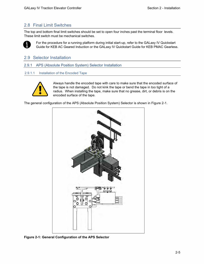
GALaxy IV Traction Elevator Controller Section 2 - Installation
2-5
2.8 Final Limit Switches The top and bottom final limit switches should be set to open four inches past the terminal floor levels. These limit switch must be mechanical switches.
For the procedure for a running platform during initial start-up, refer to the GALaxy IV Quickstart Guide for KEB AC Geared Induction or the GALaxy IV Quickstart Guide for KEB PMAC Gearless.
2.9 Selector Installation 2.9.1 APS (Absolute Position System) Selector Installation
2.9.1.1 Installation of the Encoded Tape
Always handle the encoded tape with care to make sure that the encoded surface of the tape is not damaged. Do not kink the tape or bend the tape in too tight of a radius. When installing the tape, make sure that no grease, dirt, or debris is on the encoded surface of the tape.
The general configuration of the APS (Absolute Position System) Selector is shown in Figure 2-1.
Figure 2-1: General Configuration of the APS Selector

GALaxy IV Traction Elevator Controller Section 2 - Installation
2-6
To install the APS Selector, follow steps 1 through 8 below:
Step 1: Install the top selector bracket and attach the encoded tape.
• Mount the top J-hook selector bracket to the rail. • Make sure the bracket is high enough that, when counterweight buffer is fully compressed, that
the encoded tape is still within the field of view of the APS cameras, and that nothing on the car contacts the bracket.
• Attach the encoded tape to the top bracket keeping the encoded tape as close to the rail as possible. See Figure 2-2.
• Make sure to feed the tape through the front side of the bracket first (the side facing the car), and then bend it around the top of the bracket and lace it back down. Make sure that the encoded side of the tape faces the car and that the “LEFT” markings on the tape are on the left side. See Figures 2-3 and 2-4.
• Fasten the tape with the supplied bracket and screws.
Figure 2-2: Encoded Tape Mounting – Top Bracket

GALaxy IV Traction Elevator Controller Section 2 - Installation
2-7
Figure 2-3: Front View of Encoded Tape Figure 2-4: Side View of Top Bracket
Step 2: Run down on inspection while unrolling the encoded tape.
• Run down on inspection while unrolling the tape. See Figure 2-5.

GALaxy IV Traction Elevator Controller Section 2 - Installation
2-8
• Make sure you do not kink the tape or bend it in too tight of a radius. The tape can be damaged, and it should be handled with care.
• Mount a J-hook selector bracket and guide clip with a door zone bridge for each floor. See Figure 2-6.
• When the elevator is at floor level the door zone bridge should be positioned at the midpoint between the two APS cameras. See Figure 2-14. The exact positioning of this bracket and guide clip will be set in section 2.9.2.4.
• Where there are tall floor heights or blind hoistways, mount J-hook selector brackets and guide clips without door zone bridges, at locations as needed, that will hold the encoder tape at the proper position with respect to the guide rails and APS camera. See Figure 2-7.
• Make sure your hands are clean and you do not leave any grease or dirt on the front of the tape.
Figure 2-5: Unroll the Encoded Tape
Figure 2-6: Guide Clip with Door Zone Bridge
Figure 2-7: Guide Clip without Door Zone Bridge
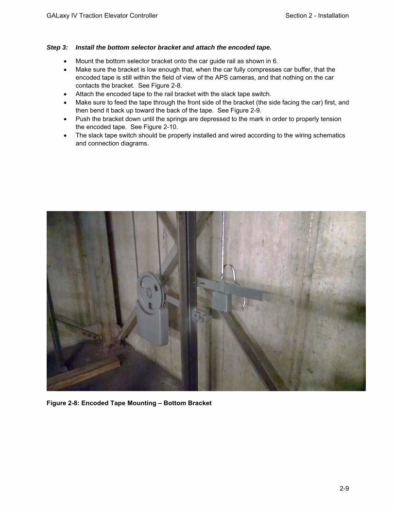
GALaxy IV Traction Elevator Controller Section 2 - Installation
2-9
Step 3: Install the bottom selector bracket and attach the encoded tape.
• Mount the bottom selector bracket onto the car guide rail as shown in 6. • Make sure the bracket is low enough that, when the car fully compresses car buffer, that the
encoded tape is still within the field of view of the APS cameras, and that nothing on the car contacts the bracket. See Figure 2-8.
• Attach the encoded tape to the rail bracket with the slack tape switch. • Make sure to feed the tape through the front side of the bracket (the side facing the car) first, and
then bend it back up toward the back of the tape. See Figure 2-9. • Push the bracket down until the springs are depressed to the mark in order to properly tension
the encoded tape. See Figure 2-10. • The slack tape switch should be properly installed and wired according to the wiring schematics
and connection diagrams.
Figure 2-8: Encoded Tape Mounting – Bottom Bracket

GALaxy IV Traction Elevator Controller Section 2 - Installation
2-10
Figure 2-9: Side View of Encoded Tape Attachment to the Bottom Bracket
Figure 2-10: Lower Bracket with Springs Properly Compressed to the Marks
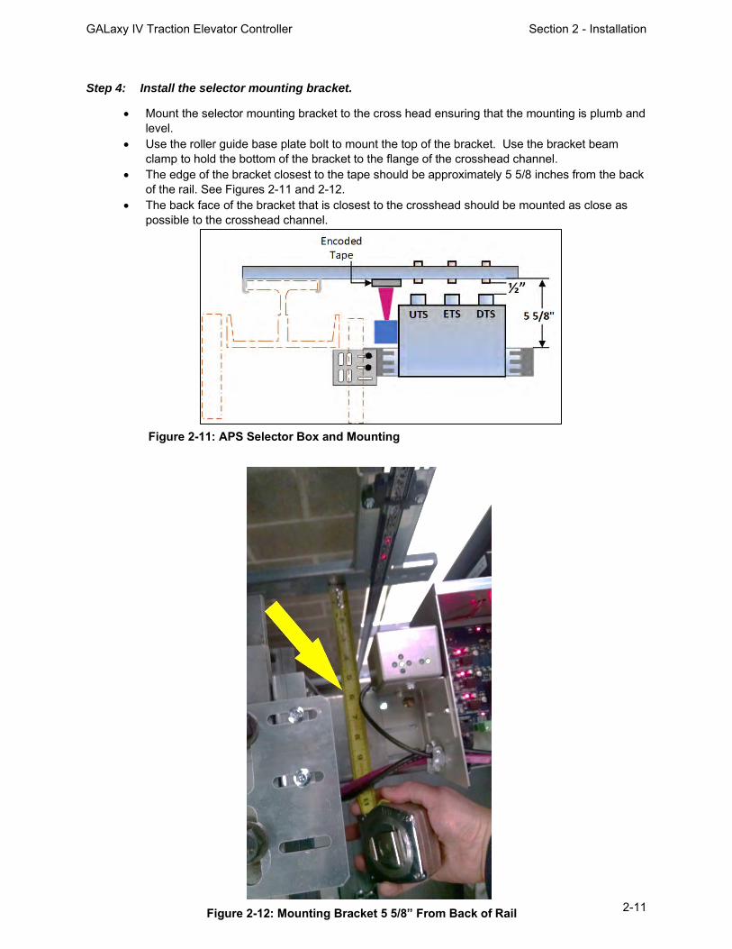
GALaxy IV Traction Elevator Controller Section 2 - Installation
2-11
Step 4: Install the selector mounting bracket.
• Mount the selector mounting bracket to the cross head ensuring that the mounting is plumb and level.
• Use the roller guide base plate bolt to mount the top of the bracket. Use the bracket beam clamp to hold the bottom of the bracket to the flange of the crosshead channel.
• The edge of the bracket closest to the tape should be approximately 5 5/8 inches from the back of the rail. See Figures 2-11 and 2-12.
• The back face of the bracket that is closest to the crosshead should be mounted as close as possible to the crosshead channel.
Figure 2-11: APS Selector Box and Mounting Bracket
Figure 2-12: Mounting Bracket 5 5/8” From Back of Rail

GALaxy IV Traction Elevator Controller Section 2 - Installation
2-12
Step 5: Install the selector box.
• Mount the selector box on the mounting bracket. • The APS camera should be centered with the encoded tape. • The face of the APS camera should be 4 inches from the face encoded tape. See Figure 2-13.
Figure 2-13: APS Camera 4 Inches from the Encoded Tape

GALaxy IV Traction Elevator Controller Section 2 - Installation
2-13
Step 6: Install brackets for UTS, DTS, and ETS actuating magnets.
• Mount a J-hook bracket with a GREEN actuating magnet for the UTS magnetic limit switch at the proper distance from the top terminal landing. See Table 2-1 for the proper distance. See Figures 2-11 and 2-14 for the proper position on the J-hook bracket.
• Mount a J-hook bracket with a RED actuating magnet for the DTS magnetic limit switch at the proper distance from the bottom terminal landing. See Table 2-1 for the proper distance. See Figures 2-111 and 2-14 for the proper position on the J-hook bracket.
• If the elevator has a reduced stroke buffer, mount J-hook brackets with actuating magnets for the ETS magnetic limit switch at the proper distance from the top and bottom terminal landings using a GREEN actuating magnet at the top terminal landing and a RED actuating magnet at the bottom terminal landing. See Table 2-1 for the proper distance.
• The actuating magnets should be positioned in the proper lane and adjusted so that the end of the magnet is 1/2 inch from the face of the magnetic switch as the magnetic switch passes the actuating magnet. See Figure 2-11.
Figure 2-14: Mounting Brackets for UTS, DTS, and ETS

GALaxy IV Traction Elevator Controller Section 2 - Installation
2-14
Step 7: Wire the APS selector.
• Figure 2-15 shows typical wiring connections for the APS selector. • The APS selector should be wired according to the job specific wiring schematic and connection
diagrams.
Figure 2-15: Typical Wiring Connections for the APS Selector
Prior to performing “Step 8” below, the GALaxy controller must be installed, and the APS selector must be properly wired according to the wiring schematics. See Section 3 of this manual.
Step 8: Perform a fine adjustment of the APS camera.
• Make the fine adjustment of the camera using the LED array on the top of the APS camera. See Figure 2-16.
• Adjust the camera so only the green LED in the middle of the 4 red arrows is on. See Figure 2-18.
• Temporarily obstruct the field of view of the APS camera for 5 seconds, and then remove the obstruction. Two red alignment spotlights should appear on the encoded tape. These spotlights represent the center of the field of view of each APS camera. Adjust the camera so the spotlights are in the center of the encoded tape. See Figure 2-17.
• Level the APS camera with a leveling device. The APS camera must be parallel and square to the encoded tape.
• The PWR and STAT LED’s indicate the status of the APS. See Table 2-2.

GALaxy IV Traction Elevator Controller Section 2 - Installation
2-15
LED Color Function OFF ON Slow Blinking (1 Hz) Fast Blinking (5 Hz)
PWR Green Supply voltage No power Power OK -- -- STAT Red Status signal No errors Reading error APS internal fault Communication error
Figure 2-18: Fine Adjustment of the Camera Sensor
Figure 2-16: LED Array on APS Camera
Figure 2-17: APS Camera Alignment Spotlights
Table 2-2: APS Camera, PWR and STAT LED’s

GALaxy IV Traction Elevator Controller Section 2 - Installation
2-16
2.9.1.2 APS Selector Floor Position Setup (Hoistway Learn)
The hoistway learn procedure requires that the selector interface board communicates properly with the main CPU through the Safety CAN bus. The hoistway learn procedure also requires that the APS camera module communicates properly with both CPUs on the selector interface board and with the main CPU in the controller.
Proceed to Section 3 of this manual, and, once the “Prepare the Car for Hoistway Learn” section is reached in section 3.3.7, return to section 2.9.1.3.
2.9.1.3 Verify that the APS Selector is Installed Correctly and Communicating
From the Diagnostic menu on the LCD Interface, select the APS Selector Can Status. Verify that the APS Sel to Main CPU RxCnt is counting, and that the On-line status equals 1. APSM, on the display, refers to the communications to the main CPU, whereas, APS2 refers to the communications to Processor 2 on the selector interface board. Continue through the menu items to verify that the CntA value for APSM is not zero, that there are no Errors or Warnings, that the alignment is centered, and that the contrast shows OK. Also verify that the APS2 status shows that the RxCnt is counting and that the On-line status equals 1. Continue to verify that the CntB value for APS2 is not zero, that there are no Errors or Warnings, that the alignment is centered, and that contrast shows OK. Note that the RxCnt for the APS2 device will increment much slower than for the Main CPU.
2.9.1.4 Setting the APS Adjustable Variables
Set the following parameters in the “APS Selector Adjustable Variables” sub-menu prior to recording the floor positions.
• Set “Top Speed” to the contract speed of the job. • Set “Number Valid Floors” to the number of floors with openings on this elevator. • Set “Number of Limits” to the number of slow down limits required per terminal landing for
the specific job speed. Refer to Table 2-1, “Slowdown Distances From Terminal Landings”. Example: 350fpm job would be set to 2 limits.
• Set UT/DT Dist. If set to zero, the distance is set automatically from the slowdown table in the manual. If this parameter is changed, it will not take effect until a learn operation is completed at the top and bottom floor. It is recommended to set this parameter to zero unless the slowdown distances need to be adjusted.
• Set UT1/DT1… UT3/DT3 if required. If set to zero, the distance is set automatically from the slowdown table in the manual. If this parameter is changed, it will not take effect until a learn operation is completed at the top and bottom floor. It is recommended to set these parameters to zero unless the slowdown distances need to be adjusted.
• Set Can Baud Rate to 0. 0 is 115.2K Baud. This parameter should not need to be changed.
2.9.1.5 Zero the Hoistway
After the APS selector parameters are setup, continue the following steps to zero the hoistway table. From the Elevator Setup menu, select Learn Hoistway and follow the flowchart shown in Figure 2-19. Notice that the number of valid floors, number of limits, and top speed will be verified. Be sure to select YES for First Time Setup and press enter. When the message, “Setup Active. Press Up or Dn to Scroll through” is displayed, press Mode to escape to the main menu. Proceed to section 2.9.1.6, “Setting Hoistway Floor Levels with APS Selector”, in the adjustment manual.

GALaxy IV Traction Elevator Controller Section 2 - Installation
2-17
Figure 2-19: Flowchart for Learn Hoistway Submenu

GALaxy IV Traction Elevator Controller Section 2 - Installation
2-18
2.9.1.6 Setting Hoistway Floor Levels with APS Selector
• Put the elevator on car top inspection. Temporarily set the car door bypass switch to the BYPASS position. Setting the car door bypass switch to the BYPASS position will allow the car to be moved on car top inspection with the car door open. All safety precautions must be followed to ensure the safety of elevator personnel and the general public when moving the car on car top inspection with the car door bypass switch in the BYPASS position.
• Move the jumper on the GALX-1133AN selector board to the SETUP position. See Figure 2-20.
Figure 2-20: APS Selector Board Setup Jumper
• Move the car on inspection so that it is exactly level with a floor. Pressing the door open button, while moving the car on inspection, will change the inspection speed to 3 fpm during the inspection run. This allows the car to be positioned at exactly floor level. The inspection speed will return to the value set for “Inspect Speed” in the “Car Motion” Sub Menu when the door open button is not pressed.
• Adjust the J-hook bracket and guide clip so the door zone bridge is positioned at the midpoint between the two APS cameras. If the alignment spotlights are not visible, temporarily obstruct the field of view of the APS camera for 5 seconds, and then remove the obstruction. Two red alignment spotlights should appear on the encoded tape. See Figures 2-17 and 2-21.

GALaxy IV Traction Elevator Controller Section 2 - Installation
2-19
• To record the floor position, press the buttons on the car operating panel in the following sequence. o Press the 2nd floor car call button o Press the 1st floor car call button o Press the 2nd floor car call button o Press the 1st floor car call button o Press the Door close button
The car call light for floors 1 and 2 will illuminate momentarily and then turn off. After the two car call lights turn off, press the following button on the car operating panel. o Press the car call button for the floor where the car is currently located.
This car call light will flash on and off for approximately 5 seconds and then remain off. This indicates that the floor position was recorded successfully. If the car call light does not flash, but remains illuminated, the floor was not recorded successfully. If the floor position was not recorded successfully, verify that the APS SEL adjustable variables are set properly.
The 1st floor car call is the car call for the bottom terminal landing. The 2nd floor car call is
the car call for the landing that is one floor above bottom terminal landing. The actual floor markings for these floors may not be “1” and “2”.
• Repeat this process until all valid floors have been recorded. • Move the jumper on the GALX-1133AN board to the RUN position and exit the car.
Set the car door bypass switch to the OFF position.
• The hoistway learn is now complete. • Position the car near a floor. • Put the car in automatic operation with the AUTO DOOR switch set to the OFF position. • The car should level into the floor. Proceed to section 3.7, “Final Adjustment”.
Figure 2-21: APS Selector Alignment Spotlights

GALaxy IV Traction Elevator Controller Section 2 - Installation
2-20
2.9.2 Tapeless Selector Installation
2.9.2.1 Tapeless Selector 7
The “Tapeless Selector 7” utilizes a governor mounted CAN Open encoder and encoder cable. The CAN Open encoder must be properly installed on a governor that has a rotating center shaft, and the encoder cable must be connected to the controller as shown in the wiring schematics and connection diagrams. The “Tapeless Selector 7” includes a leveling sensor box and a limit switch box that are to be mounted on top of the car. The general configuration of the “Tapeless Selector 7” is shown in Figure 2-22.
Figure 2-22: General Configuration of the Tapeless Selector 7 (Dimensions are in inches)

GALaxy IV Traction Elevator Controller Section 2 - Installation
2-21
To install the Tapeless Selector 7, follow steps 1 through 4 below:
Step 1: Install the limit switch box.
• Mount the limit switch box mounting bracket to the cross head ensuring that the mounting is plumb and level. See Figure 2-23.
• Use the roller guide base plate bolt to mount the top of the bracket. Use the bracket beam clamp to hold the bottom of the bracket to the flange of the crosshead channel.
• The edge of the bracket closest to the J-hook brackets should be approximately 3 inches from the back of the rail. See Figures 2-24.
• The back face of the bracket that is closest to the crosshead should be mounted as close as possible to the crosshead channel.
• Mount the limit switch box to the mounting bracket. The selector box should be positioned to allow for a distance of 1/2 inch from the face of the magnetic switch to the end of the actuating magnets that will be installed in step 3. See Figures 2-23 and 2-24.
Figure 2-23: Tapeless Selector 7 Mounting Bracket Side View

GALaxy IV Traction Elevator Controller Section 2 - Installation
2-22
• The limit switch box includes magnetic switches for the following input signals. o UT, DT o UT1, UT2, UT3 (UT4, UT5, UT6 if required) o DT1, DT2, DT3 (DT4, DT5, DT6 if required) o UTS, DTS o UN, DN o ETS (if required)
These magnetic switches are actuated by magnets as the car approaches the terminal landings. These magnets are cylindrical in shape and are mounted to brackets that are positioned at the proper distance from the terminal landings. See Step 3. The following items may vary depending on the speed of the elevator.
o The number of magnetic switches in the limit switch box o The location of the magnetic switches in the limit switch box o The size of the limit switch box
Figure 2-24: Tapeless Selector 7 Limit Switch Box Top View (Dimensions are in inches)

GALaxy IV Traction Elevator Controller Section 2 - Installation
2-23
Step 2: Install the leveling sensor box.
• Mount the leveling sensor box using the Unistrut bracket and roller guide mounting bolts. • The leveling sensor box includes sensors for inputs signals UL, DZU, DZD, and DL. See
Figure 2-25. • The leveling sensor box should be mounted such that the sensors are positioned at a 45-
degree angle with respect to the face of the rail. • Install the 8-inch floor magnets on the rail at every floor. The 8-inch floor magnet should be
placed in the corner of the rail as shown in “Detail A” in Figure 2-26. When the car is at floor level, the centerline of the 8-inch floor magnet should be at the same height as the centerline of the UL and DL sensors.
It is important to limit the side-to-side movement of the car to 1/4” between the rails to maintain consistent floor levels and to prevent nuisance faults. After final adjustment, the 8-inch floor level magnets should be secured with an adequate amount of adhesive caulk in order to prevent movement.
• Adjust the leveling sensor box and the leveling sensors so that the ends of the sensors are
1-inch from the face of the magnet. See Figure 2-26. The UL and DL sensors are mounted in slotted holes to allow fine adjustment of the “floor level zone” in section 3.7.3. However, these sensors should be set in the middle of the adjustment slot as a starting point prior to final adjustment.
Figure 2-25: Tapeless Selector 7 Leveling Sensor Box
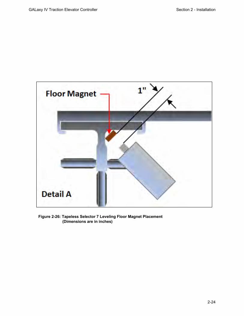
GALaxy IV Traction Elevator Controller Section 2 - Installation
2-24
Figure 2-26: Tapeless Selector 7 Leveling Floor Magnet Placement (Dimensions are in inches)

GALaxy IV Traction Elevator Controller Section 2 - Installation
2-25
Step 3: Install brackets for the limit actuating magnets.
• Mount a J-hook bracket with a GREEN actuating magnet for each magnetic limit switch at the proper distance from the top terminal landing. See Table 2-1 for the proper distance. See Figures 2-23 and 2-24 for the proper position of the actuating magnet on the J-hook bracket.
• Mount a J-hook bracket with a RED actuating magnet for each magnetic limit switch at the proper distance from the bottom terminal landing. See Table 2-1 for the proper distance. See Figures 2-23 and 2-24 for the proper position of the actuating magnet on the J-hook bracket.
• If the elevator has a reduced stroke buffer, mount J-hook brackets with actuating magnets for the ETS magnetic limit switch at the proper distance from the top and bottom terminal landings using a GREEN actuating magnet at the top terminal landing and a RED actuating magnet at the bottom terminal landing. See Table 2-1 for the proper distance.
• A J-hook bracket and GREEN actuating magnet, for the UN magnetic switch, should be positioned to activate the switch when the car is 2 inches above the top terminal floor level.
• A J-hook bracket and RED actuating magnet, for the DN magnetic switch, should be positioned to activate the switch when the car is 2 inches below the bottom terminal landing.
• The actuating magnets should be adjusted so that the end of the magnet is 1/2 inch from the face of the magnetic switch as the magnetic switch passes the actuating magnet. See Figure 2-24.
Step 4: Wire the Tapeless Selector 7.
• Figure 2-27 shows typical wiring connections for the Tapeless Selector 7. • The Tapeless Selector 7 should be wired according to the job specific wiring schematic and
connection diagrams. • Proceed to section 3, “GALaxy IV Adjustment – Combivert F5 AC Drive”.
Figure 2-27: Tapeless Selector 7 Wiring

GALaxy IV Traction Elevator Controller Section 2 - Installation
2-26
2.9.2.2 Tapeless Selector 5 The “Tapeless Selector 5” utilizes a governor mounted CAN Open encoder and encoder cable. The CAN Open encoder must be properly installed on a governor that has a rotating center shaft, and the encoder cable must be connected to the controller as shown in the wiring schematics and connection diagrams. The “Tapeless Selector 5” is similar to the “Tapeless Selector 7”. However, the “Tapeless Selector 5” includes the leveling sensors within the limit switch box and requires a J-hook bracket at each floor for mounting the floor magnet. See Figures 2-28, 2-29, and 2-30.
Figure 2-28: Tapeless Selector 5 Top View. (Dimensions are in inches)
Figure 2-29: Tapeless Selector 5 Limit Switch Box With Leveling Sensors

GALaxy IV Traction Elevator Controller Section 2 - Installation
2-27
Figure 2-30: Tapeless Selector 5 Side View. Dimensions are in inches.

GALaxy IV Traction Elevator Controller Section 2 - Installation
2-28
To install the Tapeless Selector 5, follow steps 1 through 3 below:
Step 1: Install the limit switch box with leveling sensors.
• Mount the limit switch box mounting bracket to the cross head ensuring that the mounting is plumb and level. See Figures 2-28 and 2-30.
• Use the roller guide base plate bolt to mount the top of the bracket. Use the bracket beam clamp to hold the bottom of the bracket to the flange of the crosshead channel.
• The back face of the bracket that is closest to the crosshead should be mounted as close as possible to the crosshead channel.
• Mount the limit switch box to the mounting brackets. The selector box should be positioned to allow for a distance of 1/2 inch from the face of the magnetic switch to the end of the actuating magnets that will be installed in step 3. See Figures 2-28 and 2-30.
• The limit switch box includes magnetic switches for the following input signals. o UT, DT o UT1 (UT2, UT3, UT4, UT5, UT6 if required) o DT1 (DT2, DT3, DT4, DT5, DT6 if required) o UTS, DTS o UN, DN o ETS (if required)
These magnetic switches are actuated by magnets as the car approaches the terminal landings. These magnets are cylindrical in shape and are mounted to brackets that are positioned at the proper distance from the terminal landings. See Step 3. The following items may vary depending on the speed of the elevator.
o The number of magnetic switches in the limit switch box o The location of the magnetic switches in the limit switch box o The size of the limit switch box
See Figures 2-28, 2-29, and 2-30.
Step 2: Install brackets for floor level magnets.
• Mount a J-hook bracket at each floor for the floor level magnet. See Figures 2-28 and 2-30. • Mount the narrow metal door zone brackets to each J-hook bracket for the intermediate floors. • Mount the wide metal door zone brackets to the J-hook brackets for the top and bottom
terminal floors. See Figure 2-30. • Install an 8-inch floor level magnet on each door zone bracket. • Adjust the leveling sensors so that the end of the sensors are 1 inch from the face of the floor
magnet. See Figure 2-28. This distance may be adjusted in section 3.3.8.3 to provide the correct “floor level zone”.
• When the car is at floor level, the centerline of the 8-inch floor magnet should be at the same height as the centerline of the UL and DL sensors.

GALaxy IV Traction Elevator Controller Section 2 - Installation
2-29
Step 3: Install brackets for the limit actuating magnets.
• Mount a J-hook bracket with a GREEN actuating magnet for each magnetic limit switch at the proper distance from the top terminal landing. See Table 2-1 for the proper distance. See Figures 2-28 and 2-30. for the proper position of the actuating magnet on the J-hook bracket.
• Mount a J-hook bracket with a RED actuating magnet for each magnetic limit switch at the proper distance from the bottom terminal landing. See Table 2-1 for the proper distance. See Figures 2-28 and 2-30 for the proper position of the actuating magnet on the J-hook bracket.
• If the elevator has a reduced stroke buffer, mount J-hook brackets with actuating magnets for the ETS magnetic limit switch at the proper distance from the top and bottom terminal landings using a GREEN actuating magnet at the top terminal landing and a RED actuating magnet at the bottom terminal landing. See Table 2-1 for the proper distance.
• A J-hook bracket and GREEN actuating magnet, for the UN magnetic switch, should be positioned to activate the switch when the car is 2 inches above the top terminal floor level. The UN actuating magnet should be mounted in the top hole of the wide door zone bracket at the top terminal landing. See Figure 2-30.
• A J-hook bracket and RED actuating magnet, for the DN magnetic switch, should be positioned to activate the switch when the car is 2 inches below the bottom terminal landing. The DN actuating magnet should be mounted in the middle hole of the wide door zone bracket at the bottom terminal landing. See Figure 2-30.
• The actuating magnets should be adjusted so that the end of the magnet is 1/2 inch from the face of the magnetic switch as the magnetic switch passes the actuating magnet. See Figure 2-28.

GALaxy IV Traction Elevator Controller Section 3 – GALaxy Adjustment
3-1
Section 3 - GALaxy Adjustment
3.1 Procedure for Initial Power-up of Controller
3.1.1 Checking Main Line Voltage
Prior to powering up the controller, making drive adjustments, or attempting to run the hoist motor, the following steps should be completed:
• Familiarize yourself with the wiring schematics. • Familiarize yourself with the KEB Combivert F5 Elevator Drive Technical Manual.
All safety precautions, including precautions related to electrical safety, must be followed to ensure the safety of elevator personnel and the general public.
• Before applying power to the controller, the following items should be verified by the proper electrical authority.
o Verify that the disconnecting means is properly sized and is lockable. o Verify that the voltage supplying the elevator controller is correct as indicated
on the “Controller Input” of the controller data tag. o Verify that the conductors supplying the disconnecting means are properly
sized. o Verify that the conductors from the disconnecting means to the controller are
properly sized. o Verify that power supply feeding the controller has the proper fuse protection
or circuit breaker protection. o Verify that the power supply feeding the controller is properly grounded and
that the grounding conductor is properly sized.
3.1.2 Checking Controller Voltages
Turn the main line disconnect to the ON position. Check the voltage at points R, S, and T on the AC drive. Verify that all three phases are present.
Check the voltage at fuses L1 and L2 on controller. If correct, then check the voltage at terminals LIN and 24VI with respect to ground (GND). The voltage readings should be 120VAC for LIN and 24VAC for 24VI. If these are correct, check the voltage at terminals S10, L120, & L24 with respect to ground (GND). The voltage reading at terminals S10 and L120 should read 120VAC, and L24 should read 24VAC. If any of these voltage readings are not correct, then check wiring diagram to determine the problem before continuing. Verify, from the schematic, the required voltages for FEP and HCP for this controller. Either supply can be wired for 24VAC or 120VAC. Verify the voltages on the terminals match the voltages on the schematic.
3.1.3 Verifying Operation of the Main CPU
Verify that the “axy” of “GALaxy”, displayed on the 1005/1101 LCD Interface, is flashing. If the “axy” is flashing, then proceed to the next step. If the “axy” is not flashing, check voltages at the 5V to 0V terminals on the 1102 Main I/O Board, to ensure 5VDC is present across these terminals. If 5VDC is present and the “axy” on the 1005/1101 LCD Interface is not flashing, then contact factory.

GALaxy IV Traction Elevator Controller Section 3 – GALaxy Adjustment
3-2
3.2 Start-up Procedures
3.2.1 Requirements for a running platform during initial startup
1) Wire Motor and Main Line Power as shown in the job connection diagrams. 2) Install and wire Governor as shown in the job connection diagrams. 3) Wire the motor encoder cable as shown in the job connection diagrams. 4) If controller is equipped with dynamic braking resistors, wire the DBR temperature sensor to the
temperature sensor board. 5) Add temporary connections on the GALX-1102 Main I/O Board and Expansion I/O boards as
shown in Figures 3-1, 3-2, 3-3, and 3-4.
All temporary connections must be removed before placing the elevator in service.
Figure 3-2: Fire I/O Expansion Board Figure 3-3: Earthquake I/O Expansion Board (if used)
Figure 3-1: GALX-1102AN Main I/O Board With Run Bug. See Figure 3-4 For Run Bug Stop Switch

GALaxy IV Traction Elevator Controller Section 3 – GALaxy Adjustment
3-3
6) Set the toggles switches on the GALX-1102 Main I/O Board as show in Figure 3-4.
Figure 3-4: GALX-1102AN Main I/O Board
See Figure 3-1 For Run Bug Connections

GALaxy IV Traction Elevator Controller Section 3 – GALaxy Adjustment
3-4
7) Check/set parameters in the controller LCD user interface. See “GALaxy IV Controller Settings”
in Table 3-1.
Preset the following parameters from the LCD User Interface “Adjustable Variables” menu. Safety Processor Adjustable Variables Submenu (Motor Encoder Speed Feedback):
Top Speed (contract speed fpm) INSP Velocity (set to 140)
Encoder RPM (set to motor rpm) Leveling Vel (set to 140)
Encoder PPR (set to motor encoder PPR) ETS UP VEL (set to Top Speed – only used for reduced stroke buffer)
Encoder Type (set to 4 = incremental) ETS DOWN VEL (set to Top Speed – only used for reduced stroke buffer)
Control Type (set to 2 = Tract DF) Soft Stop Time (set to 3)
2 Stop (0 = Multi – Stop; 1 = 2 Stop) PAL ETS UP Vel (set to Top Speed)
Rear Doors (0 = Front Only; 1 = Rear) PAL ETS DN Vel (set to Top Speed)
UTS Velocity (set to Top Speed)
DTS Velocity (set to Top Speed)
NTS Processor Adjustable Variables Submenu
Top Speed (contract speed fpm) DT Velocity (set to Top Speed)
Encoder RPM (set to motor rpm) UT1 Velocity (set to Top Speed)
Encoder PPR (set to motor encoder PPR) DT1 Velocity (set to Top Speed)
Encoder Type (set to 0 if using APS; set to 1 if using tapeless selector) UTn Velocity (set to Top Speed)
UT Velocity (set to Top Speed) DTn Velocity (set to Top Speed)
Car Motion Submenu
When Using Tapeless Selector: When Using APS Selector:
Top Speed (set to Contract Speed) Top Speed (set to Contract Speed)
Inspect Speed (set to 25 FPM) Inspect Speed (set to 25 FPM)
Encoder PPR (set to 10,000 PPR) Encoder PPR (not Used)
Encoder RPM (set to governor RPM, See NOTE below) Encoder RPM (not used)
Motor RPM (= LM02 value in KEB drive) Motor RPM (LM02 value in KEB Drive)
System Options Submenu
Drive Baud Rate = 2 (57,600) KEB Dpy Type = 1 (LCD Display)
Encoder Type = 0
EPRS Controller Parameters =>Adjustable Variables => Modified Motion
EP Recov Speed = 15
EP Top Speed = 15
EP Target Dist = 2
Table 3-1: GALaxy IV Controller Settings

GALaxy IV Traction Elevator Controller Section 3 – GALaxy Adjustment
3-5
NOTE: For jobs with Reduced Stroke Buffer, the parameters associated the ETSLD (Emergency Terminal Speed Limiting Device), must be preset as described below.
• Verify that the Reduced Stroke Buffer jumper is installed on the MAIN I/O board. • Verify that the Safety Processor variable Buffer Type is set to 1=Reduced Stroke. • To preset the Safety PAL ETS up and down velocity set points, temporarily install the
ETSLD Test jumper on the MAIN I/O board. • Set the Safety Processor variable ETS Setup Mode to 1=AdjPALets. • Preset the following parameters:
o PAL ETS Up Vel (Set to top speed) o PAL ETS Dn Vel (Set to top speed)
• Remove the ETSLD Test jumper from the MAIN I/O board. • Set the ETS Setup Mode parameter to 0=Norm. • Leave the Reduced Stroke Main I/O board jumper installed and leave the Safety
Processor variable for Buffer Type set for reduced stroke.
NOTE: For governor mounted encoders, to calculate the RPM, divide the contract speed of the car by the distance traveled in one revolution with the governor as shown below: RPM = Speed fpm/ (diameter GOV (in feet) * pi) For a 1 ft. diameter governor: RPM = 350/ (1*pi) = 350/3.1415 = 111.4 For a 16 in diameter governor (16/12 = 1.33ft) : RPM = 350/ (1.33* 3.1415) = 350/4.188 = 83.5 Table 3-2 can be used in calculating the governor RPM. For the governor diameter for this project, identify the associated “Divisor” in red from Table 3-2. Divide the car speed by the “Divisor” to determine the governor RPM.
Gov. Diameter Divisor
10" 2.616
11" 2.877
12" 3.141
13" 3.402
14" 3.662
15" 3.926
16" 4.187 The preset values entered for the normal terminal limit velocities and the emergency terminal limit
velocities are temporary settings. These values must be set as described in section 3.3.9 before the elevator is placed into service
Table 3-2

GALaxy IV Traction Elevator Controller Section 3 – GALaxy Adjustment
3-6
8) Check/set parameters in the KEB drive. For geared traction with an induction motor, see “KEB
AC Geared Drive Settings for Start-up” in Table 3-3. For gearless traction with a PMAC gearless motor, see “KEB PMAC Gearless Drive Settings for Start-up” in Table 3-4.
Preset the following parameters from the KEB drive keypad for Geared Machine.
Drive Mode Settings: (This Must Be Completed First)
US03 Motor Type = Induction Geared
US04 Control Type = Serial Speed DIN66019 serv 49
LI15 Direction Selection Inputs = UP & DN, Serial Control Word + Function by Dir. Inputs
US05 Load Configuration = Write Config. To Drive
Control Settings
LC01 Closed Loop FOC =2
LC03 KP Speed Acceleration = 3000
LC04 KP Speed Deceleration = 3000
LC08 KI Speed Acceleration = 250
LC09 KI Speed Deceleration = 250
Encoder Data
LE01 Encoder Interface = Incremental
LE02 Encoder PPR = Motor Encoder PPR
LE03 Swap Encoder Channels = (See page 4 or KEB manual)
LE05 Encoder Multiplier = 2 (Geared)
Motor Data
LM01 Motor HP = Nameplate HP
LM02 Rated Motor Speed = Nameplate Full Load RPM
LM03 Rated Motor Current = Nameplate AMPS
LM04 Rated Motor Frequency = Nameplate HZ
LM05 Rated Motor Voltage = Motor Voltage
LM06 Motor Power Factor = 0.9 (if unknown)
LM07 Rated Motor Torque = Nameplate (PM Only)
LM08 Electric Motor Protection = ON
LM09 Ele. Mtr. Protect. Current = Nameplate AMPS
Machine Data
LN01 Sheave Diameter = inches
LN02 Gear Reduction Ratio = Nameplate value, or calculate using the following: (Sheave Dia. Inches * 3.1415 * Motor RPM) / (Contract Speed fpm * 12)
LN03 Roping Ratio = 1.1 or 2.1
LN04 Load Capacity = Car Capacity
When Using EPRS (UPS Emergency Power Rescue)
LI04 Input 1 Function (I1) = UPS Operation
LS10 Battery Operation Speed = 15 ft / min
LT03 Speed Start Delay = 1.5 sec
LT10 Brake Drop Delay = 0.1 sec
Table 3-3: KEB AC Geared Drive Settings for Start-up

GALaxy IV Traction Elevator Controller Section 3 – GALaxy Adjustment
3-7
Preset the following parameters from the KEB drive keypad for PMAC Gearless Machine.
Drive Mode Settings: (This Must Be Completed First)
US03 Motor Type = PM synchronous Gearless
US04 Control Type = Serial Speed DIN66019 serv 49
LI15 Direction Selection Inputs = UP & DN, Serial Control Word + Function by Dir. Inputs
US05 Load Configuration = Write Config. To Drive
Control Settings (see G. A. L. Manual Section 3.7.2)
LC01 Closed Loop FOC =2
LC03 KP Speed Acceleration = 3000
LC04 KP Speed Deceleration = 3000
LC08 KI Speed Acceleration = 250
LC09 KI Speed Deceleration = 250
Encoder Data
LE01 Encoder Interface = Endat
LE02 Encoder PPR = Motor Encoder PPR (Endat = 2048)
LE03 Swap Encoder Channels = (See page 4 or KEB manual)
LE05 Encoder Multiplier = 8 (Gearless)
Motor Data
LM01 Motor HP = Nameplate HP
LM02 Rated Motor Speed = Nameplate Full Load RPM
LM03 Rated Motor Current = Nameplate AMPS
LM04 Rated Motor Frequency = Nameplate HZ
LM05 Rated Motor Voltage = Motor Voltage
LM06 Motor Power Factor = 0.9 (if unknown)
LM07 Rated Motor Torque = Nameplate (PM Only)
LM08 Electric Motor Protection = ON
LM09 Ele. Mtr. Protect. Current = Nameplate AMPS
Machine Data
LN01 Sheave Diameter = inches
LN02 Gear Reduction Ratio = 1:1 for gearless
LN03 Roping Ratio = 1:1 or 2:1
LN04 Load Capacity = Car Capacity
When Using EPRS (UPS Emergency Power Rescue)
LI04 Input 1 Function (I1) = UPS Operation
LS10 Battery Operation Speed = 15 ft / min
LT03 Speed Start Delay = 1.5 sec
LT10 Brake Drop Delay = 0.1 sec
NOTE: Other drive parameters have been preset in the factory and may need to be adjusted in
the field. See Table 3-6 for additional “KEB AC Geared Drive Settings”. See Table 3-7 for additional “KEB PMAC Gearless Drive Settings”.
Table 3-4: KEB PMAC Gearless Drive Settings for Start-up
GALaxy IV Traction Elevator Controller Section 3 – GALaxy Adjustment
3-8
9) Verify the PIC and PAL fault LED’s are off. See the GALX-1102AN Main I/O Board in Figure 3-4. If these LED’s are on, refer to Section 04 Troubleshooting.
10) Verify the settings of the main brake pick and hold voltages as described below. • Navigate to the "Adjustable Variables" menu, and "Car Brake" sub menu on the LCD
Interface. • Set the "Brake Pick Volt", "Brake Hold Volt" and "Brk AC L-L Volt" to the proper values. • Verify these voltages at the brake board AC1/AC2/AC3 and BK+/BK- terminals once it is
possible to pick the brake. • Verify proper operation of the main brake once it is possible to command a run.
11) If the elevator uses an emergency brake, verify the emergency brake pick and hold voltages as described below. • Navigate to the "Adjustable Variables" menu, and "Car Brake" sub menu on the LCD
Interface. • Set the "EmBk Pick Volt", "EmBK Hold Volt" and "EMBk L-L VAC" to the proper values. • Verify these voltages at the brake board AC1/AC2/AC3 and BK+/BK- terminals once it is
possible to pick the brake. • Verify proper operation of the emergency brake once it is possible to command a run.
• Verify that the elevator is safe to operate as a running platform and that all individuals are clear of moving machinery.
• Make sure all hoistway and car doors are closed. • If at all possible, place the car in the middle of the hoistway.
12) Perform the KEB Motor Learn procedure as described below.
• Set “Inspect Speed” in the “Adjustable Variables Car Motion” submenu to 0. • Prevent the main machine brake from lifting. • Set LL01 (Motor Tuning) = Start in the KEB drive. • Initiate and up or down inspection command until the KEB keypad displays "Calculation
Complete" (takes 2 to 5 minutes). • Set “Inspect Speed” in the “Adjustable Variables Car Motion” submenu to the desired value. • Return the main machine brake to its proper operating state.
13) For gearless traction with a PMAC gearless motor, perform the KEB Encoder Learn
procedure as described below. For geared traction with induction motor proceed to step 14). Encoder Learn: SPI – Stationary Pole Identification: • Machine is ROPED. • Set “Inspect Speed” in the “Adjustable Variables Car Motion” submenu to 0. • Prevent the main machine brake from lifting. • Set LL05 (SPI) = Start in the KEB drive. • Initiate an up or down inspection command until the KEB keypad displays “Complete”. • Set “Inspect Speed” in the “Adjustable Variables Car Motion” submenu to the desired value. • Return the main machine brake to its proper operating state.

GALaxy IV Traction Elevator Controller Section 3 – GALaxy Adjustment
3-9
14) Verify that the motor rotation direction and speed are correct. If the motor rotation direction and speed are not correct, verify that the LE03 parameter in the drive is set to the correct value as described below.
Determining LE03 Setting (Motor direction & A/B channels). • Run the elevator on inspection. Is the motor turning in the correct direction? If Yes, then set
LE03=Nothing Reversed. If No, then set LE03=Inverted Rotation. • Run the elevator UP on inspection, empty car. Is the Motor Current too high? If Yes, then
set LE03=A/B Swapped. If No, then set LE03=Nothing Reversed. • If the motor turns in the wrong direction AND the Motor Current is too high, then set to
LE03=A/B Swapped & Inverted rotation.
3.2.2 Check Inspection Speed
1) From the 1005/1101 LCD interface, navigate to the "Adjustable Variables" menu, "Car Motion" and set the "Inspect Speed = 25".
2) Run the elevator on inspection operation and check the speed with a handheld tachometer. 3) The speed of the elevator should be 25 fpm. If the speed is not 25 fpm, adjust the speed by
changing LN01 (Traction Sheave Diameter) parameter in the “Machine Data” menu until the speed is 25 fpm (within +/- 2 fpm).
3.2.3 Complete the Installation of Equipment
Before beginning the adjustment process, the installation of all equipment should be complete including the following items. See Section 2 for the installation procedures.
• All field wiring, safety circuits, and safety devices should be installed. • The APS or Tapeless selector system should be installed including the “door zone bridge”
guide clips for the APS selector, or the door zone magnets for the Tapeless selector. • All Normal and Emergency Terminal limit switches should be installed. • All car doors and car door electric contacts or car door interlocks should be installed. • All hoist doors and hoistway door interlocks should be installed. • The car should be properly counterbalanced.
3.3 Adjustment Procedures
• Remove all temporary connections. • Verify that all safety circuits and safety devices are installed and functioning properly. • Verify that all car door electric contacts or car door interlocks are functioning properly. • Verify that all hoistway door interlocks are functioning properly. • Verify that all hoistway doors and car doors are closed. • Verify that the elevator is safe to operate and that all individuals are clear from moving
equipment.

GALaxy IV Traction Elevator Controller Section 3 – GALaxy Adjustment
3-10
3.3.1 Verify Inspection Operation
The car should be ready to run on inspection operation. Select the “Elevator Status” on the 1005/1101 LCD interface. The display should show “Out of Service” on the first line and “Inspection Mode” on the second. Scroll down the “Elevator Status” display until “SPB Vel” is shown. The “Svc=” will display one of the following types of inspection:
• “MR INS” (Machine Room Inspection) • “CT INS” (Car Top Inspection) • “ACCESS” (Access Operation) • “IC INS” (In Car Inspection) • “AUTO” (Not on Inspection)
The “inspection string” consists of contacts from the inspection switches and the gate and lock bypass switches in series as shown in Figure 3-5. Only one of the five inputs listed above should be on for the car to run.
NOTE: Any one of the following conditions will generate an inspection error.
• More than one inspection input is on • No inspection input is on • Gate or Lock Bypass switch in the BYPASS position when the car is not on car top inspection
To run the car on machine room inspection, set the machine room inspection switch to the INSP position. Select the “Elevator Status” on the 1005/1101 LCD interface. “MR INS” should be displayed. If the controller is not on machine room inspection, then verify all switch positions and wiring before proceeding
Figure 3-5: Inspection Circuit

GALaxy IV Traction Elevator Controller Section 3 – GALaxy Adjustment
3-11
3.3.2 Verify the Main CPU Velocity Feedback
1) From the 1005/1101 LCD interface, select the "Elevator Status" menu, and then scroll down or up until the display shows "Dmd" and "Vel". While running on inspection, monitor the controller demand speed "Dmd" and the speed feedback "Vel". These values should both display 25.
2) If using an APS selector, the “Dmd” and “Vel” should both display 25 fpm. If “Dmd” and “Vel” do not match, verify the proper installation of the APS selector. See section 2.9.1.3.
3) If using a Tapeless selector, verify that the “Dmd” and “Vel” feedback, on the 1005/1101 LCD,
both display 25 fpm when the car is running on inspection operation. If “Dmd” and “Vel” do not match, check the Encoder RPM, PPR and TYPE parameters from the “Adjustable Variables” menu, and verify that these parameters are set properly. If the Encoder PPR and Type are set properly, the Encoder RPM value may need to be adjusted incrementally until the “Vel” matches the “Dmd” at 25 fpm (within +/- 2 fpm), when the car is running on inspection operation.
4) If the “Dmd” speed, the “Vel” speed, and the handheld tachometer speed (see section 3.2.2) all
display 25 fpm when the car is running on inspection, proceed to section 3.3.3. If not, contact GAL Technical Support.
3.3.3 Verify the Encoder Direction for the Main CPU
1) From the LCD interface "Elevator Status" menu, scroll down or up to display "Dir" and "DP". While moving the car on inspection, monitor "Dir" (direction) and "DP" (pulse counts). "Dir" should display "Up" when the car is moving up, and "Dn" when the car is moving down. The value of "DP" should increment when the car is moving up and should decrement when the car is moving down.
2) If using an APS selector, the “Dir” should display “Up” when the car is moving up and “Dn” when
the car is moving down. The value of “DP” should increment when the car is moving up and should decrement when the car is moving down. If the direction is incorrect or the pulse counts change in the wrong direction, the APS selector should be verified for proper installation. See section 2.9.1.3.
3) If using a Tapeless selector, the the “Dir” should display “Up” when the car is moving up and “Dn”
when the car is moving down. The value of “DP” should increment when the car is moving up and should decrement when the car is moving down. If the direction is incorrect or the pulse counts change in the wrong direction, then the encoder direction to the controller must be changed. From the 1005/1101 LCD Interface, navigate to the "Adjustable Variables" menu, "Car Motion" and set the "Encoder Dir = 1" if already 0 or set to 0 if already 1. The car may get an unintended motion fault (gripper fault) when the parameter is changed. If so, then reset the unintended motion fault from the “Reset / View Faults” menu, “Reset Gripper / EBK Fault” submenu.
3.3.4 Match Feedback Velocity and Direction
1) Place the car on machine room inspection and position the car in the middle of the hoistway. 2) In the “Adjustable Variables”, “Car Motion” submenu, set the “Inspect Speed” parameter to 50
fpm.
3) Navigate to the “Elevator Setup”, “Match Feedback Vel & Dir” menu and press Enter.
4) Follow the instructions on the LCD interface. See section 5.2.43, Figure 5-43.

GALaxy IV Traction Elevator Controller Section 3 – GALaxy Adjustment
3-12
3.3.5 Verify Safety Processor Velocity and Direction Feedback
1) After completing the “Match Feedback Vel & Dir” procedures in section 3.3.4, verify that the secondary velocity and direction feedback from the Safety Processor are correct.
2) From the 1005/1101 LCD interface, select the "Elevator Status" menu and then scroll down or up
until the display shows "SPB Vel". The direction will show as a “U” or “D” next to the car speed. The speed displayed should match the car’s actual speed, and the displayed direction should match the car’s direction.
3) If the “SPB Vel” is not correct, increment or decrement the value of “Encoder RPM” in the “Safety
Proc Adj Vars” submenu, until the “SPB Vel” is correct.
4) If the displayed direction is not correct, change the setting of “Encoder Dir” parameter in the “Safety Proc Adj Vars” submenu. If the parameter is 0, then set it to 1. If the parameter is 1, then set it to 0.
3.3.6 Verify NTS Processor Velocity and Direction Feedback
1) After completing the “Match Feedback Vel & Dir” procedures in section 3.3.4, verify that the third velocity and direction feedback from the NTS Processor are correct.
2) From the 1005/1101 LCD interface, select the "Elevator Status" menu and then scroll up or down
until the display shows "NTS Vel". The direction will show as a “U” or “D” next to the car speed. The speed displayed, should match the car’s actual speed, and the direction should match the car’s direction.
3) If using a Tapeless Selector and the “NTS Vel” is not correct, increment or decrement the value of
“Encoder RPM” in the “NTS Proc Adj Vars” sub menu, until the “NTS Vel” is correct. If using an APS selector, the “NTS Vel” should be correct. If the “NTS Vel” is not correct, verify the proper installation of the APS selector. See section 2.9.1.3.
4) If using a Tapeless Selector and the displayed direction is not correct, change the setting of the
“Velocity Dir” parameter in the “NTS Proc Adj Vars” sub menu. If the parameter is 0, then set it to 1. If the parameter is 1, then set it to 0. If using an APS selector, the displayed direction should be correct. If the displayed direction is not correct, verify the proper installation of the APS selector. See section 2.9.1.3.
3.3.7 Hoistway Learn Procedure
If using an APS selector, return to section 2.9.1.3, “Verify that the APS Selector is Installed Correctly and Communicating”. Complete sections 2.9.1.3 through 2.9.1.6, “Setting Hoistway Floor Levels with APS Selector”. After completing section 2.9.1.6, return to this section, 3.3.7, and proceed to step 1 below.
If using a Tapeless selector, proceed to step 1 below.
1) Verify that the “UL”, “DL” and “DZ” inputs are functioning properly.
• As the car approaches a floor level in the up direction, the “UL” input should turn on first, the “DZ” input should turn on second, and the “DL” input should turn on third.
• As the car approaches a floor in the down direction, the “DL” input should turn on first, the
“DZ” input should turn on second, and the “DL” input should turn on third.

GALaxy IV Traction Elevator Controller Section 3 – GALaxy Adjustment
3-13
2) Verify that the normal limits are functioning properly.
• The “UN” input should turn off and stop the car in the up direction when the car is
approximately 2 inches above the top terminal landing.
• The “DN” input should turn off and stop the car in the down direction when the car is approximately 2 inches below the bottom terminal landing.
3) Verify that the limits at the terminal landings are functioning properly as the car approaches and
leaves the terminal landings. See Table 2-1, “Slowdown Distances from Terminal Landings”, and the job schematics, for the limits required for a specific elevator.
• As the car approaches the terminal landings the inputs for the limits should turn OFF in the correct sequence.
• As the car leaves the terminal landings the inputs for the limits should turn ON in the
correct sequence.
4) If using an APS selector, proceed to section 3.3.8, “Adjust the Elevator”.
5) If using a Tapeless selector, run the car down on inspection until it stops on the down normal limit. Verify that the “DN and DL” input LED’s are both off and that the "UL" and "DZ" LED's are on.
6) Navigate to the "Elevator Setup" menu, "Learn Hoistway" submenu. The learn procedure can be
performed automatically by selecting “Auto” from the menu items or performed manually by choosing “Insp” from the menu items. After choosing the learn method, follow the instructions displayed on the LCD interface. See section 5.2.44.1, “Learn Hoistway for Tapeless Selector”
• In general, the car will run up from the "down normal limit" to the "up normal limit" at 30
fpm (this speed is fixed and cannot be changed). During this learn run, the DP count for each floor level and each limit switch will be stored in memory.
• NOTE: The car must run the entire hoistway without stopping.
• When the elevator starts a hoistway learn, the display will change to show the car velocity and the position count. Verify that the position count is incrementing as the elevator moves up. Also, as the elevator passes each floor, the pulse count and distance for that floor should change and be stored. The pulse count for the terminal slowdowns will also be stored. The elevator will stop when it reaches the up normal limit.
7) Follow the instructions on the LCD interface by placing the car on inspection. The LCD will display “Hoistway Learn Complete”.

GALaxy IV Traction Elevator Controller Section 3 – GALaxy Adjustment
3-14
3.3.8 Adjust the Elevator
• Prepare the elevator to move on automatic operation. • Verify that the “AUTO DOOR” switch is in the “OFF” position • Verify that the machine room independent switch is set to the “IND” position. • Verify that the elevator is safe to operate and that all individuals are clear from moving
equipment. • Verify that the elevator is secured from the general public.
3.3.8.1 Automatic Run
1) Move the elevator on inspection until the “DZ” and “DL LEDs are on. Set the machine room
inspection switch to the “NORM” position. The elevator should level down to floor level. 2) The elevator should now be idle at floor level and ready for an automatic run. The default
parameter settings for the ride quality should be adequate for an initial run. From the 1005/1101 LCD interface, navigate to the "Set Calls and Lockouts" menu, "Setup Car Calls" submenu, and enter a car call. The elevator should run to answer the call. When the elevator levels in and stops at the floor, the doors will remain closed. At this point the acceleration and deceleration of the car should be smooth and stepless regardless of the distance of run.
3) Verify the high speed of the car, by making high speed runs while observing the “Elevator Speed”
on the “Home” screen of the drive’s LCD display. The speed displayed on the drive should match the speed displayed on the 1005/1101 LCD interface, "Elevator Status" menu, "Dmd" and "Vel". This speed should also match the speed displayed on for the safety processor display "SPB Vel" and the NTS Processor “NTS Vel” (within +/- 2 fpm).
4) If the speed is slightly under or over contract speed, adjust the speed by changing the Traction Sheave Diameter drive parameter, LN01. If the LN01 parameter is changed, re-verify the Main CPU velocity, the Safety Processor velocity, and the NTS processor velocity are correct. If these velocities are not correct, see sections 3.3.2, 3.3.5, and 3.3.6 for adjustment procedures.
3.3.8.2 Fine Tune the Ride Quality
The main CPU provides a digital speed command, or S-curve profile, to the drive, and the drive controls the motor speed and torque in order to move the elevator at the commanded speed. The default controller and drive parameters should provide a smooth elevator ride quality with a moderate floor-to-floor performance time. For a more aggressive floor-to-floor performance time, adjustments can be made to the S-curve parameters in the “Adjustable Variables”, “Car Motion” sub menu. Figure 3-6 shows a typical graph of the elevator’s S-curve profile. The S-curve parameters are listed on the graph within the portion of the S-curve controlled by the specific parameter. In general, the elevator’s floor-to-floor time can be changed by changing the value of the following parameters.
• Soft Start Jerk: Increase value to decrease floor-to-floor time • Acceleration: Increase value to decrease floor-to-floor time • Roll Over Jerk: Increase value to decrease floor-to-floor time • Decel Jerk: Increase value to decrease floor-to-floor time • Deceleration: Increase value to decrease floor-to-floor time • Floor Targ Dis: Decrease value to decrease floor-to-floor time
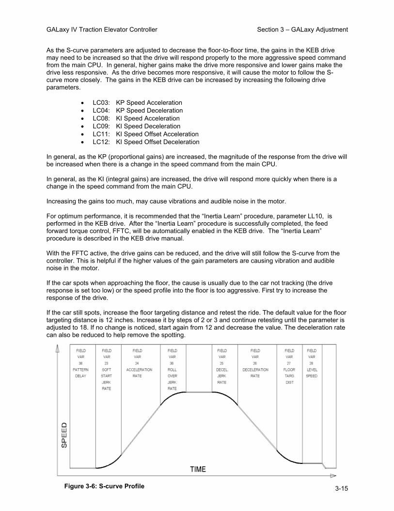
GALaxy IV Traction Elevator Controller Section 3 – GALaxy Adjustment
3-15
As the S-curve parameters are adjusted to decrease the floor-to-floor time, the gains in the KEB drive may need to be increased so that the drive will respond properly to the more aggressive speed command from the main CPU. In general, higher gains make the drive more responsive and lower gains make the drive less responsive. As the drive becomes more responsive, it will cause the motor to follow the S-curve more closely. The gains in the KEB drive can be increased by increasing the following drive parameters.
• LC03: KP Speed Acceleration • LC04: KP Speed Deceleration • LC08: KI Speed Acceleration • LC09: KI Speed Deceleration • LC11: KI Speed Offset Acceleration • LC12: KI Speed Offset Deceleration
In general, as the KP (proportional gains) are increased, the magnitude of the response from the drive will be increased when there is a change in the speed command from the main CPU. In general, as the KI (integral gains) are increased, the drive will respond more quickly when there is a change in the speed command from the main CPU. Increasing the gains too much, may cause vibrations and audible noise in the motor. For optimum performance, it is recommended that the “Inertia Learn” procedure, parameter LL10, is performed in the KEB drive. After the “Inertia Learn” procedure is successfully completed, the feed forward torque control, FFTC, will be automatically enabled in the KEB drive. The “Inertia Learn” procedure is described in the KEB drive manual. With the FFTC active, the drive gains can be reduced, and the drive will still follow the S-curve from the controller. This is helpful if the higher values of the gain parameters are causing vibration and audible noise in the motor. If the car spots when approaching the floor, the cause is usually due to the car not tracking (the drive response is set too low) or the speed profile into the floor is too aggressive. First try to increase the response of the drive. If the car still spots, increase the floor targeting distance and retest the ride. The default value for the floor targeting distance is 12 inches. Increase it by steps of 2 or 3 and continue retesting until the parameter is adjusted to 18. If no change is noticed, start again from 12 and decrease the value. The deceleration rate can also be reduced to help remove the spotting.
Figure 3-6: S-curve Profile

GALaxy IV Traction Elevator Controller Section 3 – GALaxy Adjustment
3-16
3.3.8.3 Adjust the Stop
When at floor level the “UL, DL, & DZ” input LEDs should be on. If the elevator continually tries to seek floor level by re-leveling up and down, try the following steps to correct the problem:
• Increase the response of the drive by increasing the Integral Offset gains (added to the integral gains at the start and stop) – LC11 and LC12
• Reduce the leveling and re-leveling velocity parameters from the 1005/1101 LCD interface "Adjustable Variables" menu, "Car Motion", "Leveling Speed" and "Relevel Speed".
• If the car still oscillates, adjust the "floor level zone" on the selector. For a Tapeless selector, the "floor level zone" is increased by moving the "UL" and "DL" sensors closer together. For an APS selector, the “floor level zone” is increased by increasing the value of the “APS Dead Zone” parameter in the “Adjustable Variables”, “Car Motion” submenu in the 1005/1101 LCD interface. To fine tune the floor level accuracy, determine if the controller is set to stop when "UL" and "DL" signals turn on, or if controller is set to stop off of a combination of the “UL” and “DL” signals and the position count. From the 1005/1101 LCD interface, navigate to the "Adjustable Variables" menu, "Car Motion" and view the "Stop On Pos Cnt" variable. If "Stop On Pos Cnt = 0", then the controller is set to stop when the "UL” and "DL" signals turn on. If "Stop On Pos Cnt = 1", then the controller is set to stop on a combination of the “UL” and “DL” signals and the position count. With a Tapeless selector and with "Stop On Pos Cnt = 0", the floor levels should be set by accurately setting the floor level magnet at each floor. For proper operation, the floor magnets should be set to exactly floor level. After the floor levels are set properly, perform another hoistway learn procedure. With an APS selector and with "Stop On Pos Cnt = 0", the floor levels should be set by accurately recording the floor position when using an APS selector. If the “floor level zone” needs to be increased to prevent “nuisance” re-leveling, the floor level accuracy can be maintained by setting the “Stop on Pos Cnt =1” and performing the following adjustments. From the 1005/1101 LCD interface, navigate to the "Hoistway Tables" menu, "DZ & LZ Offset, Sel Cnt" and adjust "Dn Lev Dist" and "Up Lev Dist". The units for these variables are in "pulse counts". With "Stop On Pos Cnt =1" the car will continue to move for the "Dn Lev Dist" or "Up Lev Dist" after "UL” and “DL" turn on. Use the "Dn Lev Dist" and the "Up Lev Dist" parameters to make level changes at all floors. To make level changes at individual floors, perform the following adjustments. From the 1005/1101 LCD interface, navigate to the "Hoistway Tables" menu, "FL and FL Offset Count", and the offset count can be adjusted. These variables introduce an offset (+/‐) to the stored floor count that was determined in the hoistway learn procedure.
NOTE: The number of pulse counts per inch can be viewed from the 1005/1101 LCD interface, "Hoistway Tables", "DZ & LZ Offset, Sel Cnt”, "Pulses / Inch".
NOTE: For a Tapeless selector the floor magnet must be set properly at floor level, and for an APS selector the floor level must be accurately recorded. If too large of values are entered into "Dn Lev Dist", "Up Lev Dist", or "Offset", this will cause the car to drive past the floor and re‐level.

GALaxy IV Traction Elevator Controller Section 3 – GALaxy Adjustment
3-17
If the car stops hard on the brake, then make the following adjustments. From the 1005/1101 LCD interface navigate to the "Adjustable Variables" menu, "Car Motion", and adjust both "Brake Drop Del" (brake drop delay) and "Soft Stop Time". These variables should be adjusted so that zero speed is observed at the end of the run prior to the brake setting. The controller should hold the car at zero speed for the duration of the "Soft Stop Time" which should continue while the brake is setting and for a short time after the brake sets. The soft stop time MUST be set to at least 1.2 seconds LONGER than the brake drop delay. The "Soft Stop Time" setting in the 1005/1101 LCD interface should be compared with the setting in the "Safety Proc Adj Vars" menu, "Soft Stop Time". The setting of "Soft Stop Time" in the Safety Processor should be greater than the "Soft Stop Time" setting in the main CPU. A typical setting for the Safety Processor soft stop time is 3 seconds. After the “Soft Stop Time” expires, the drive will ramp the motor torque down to zero, and the load will be transferred to the main brake. Drive parameter, LT13, “Current Ramp Down Time”, should be set to allow the current in the motor to ramp down gradually after the “Soft Stop Time” expires. Also, the “MC Drop Dly Tim” should be set to allow the MC contactor to de-energize after the LT13 timer has expired.
3.3.8.4 Adjust the Start
To provide a proper start, from the 1005/1101 LCD interface, navigate to the "Adjustable Variables" menu, "Car Motion" and adjust "Brake Pick Del" (brake pick delay), "Pattern Delay", and "Soft Start Jerk". Initially, set the brake pick delay to 0 and increase the pattern delay by 0.1 seconds until the controller picks the brake completely before the motor starts to move. If roll back occurs, then reduce the pattern delay until there is no roll back. Sometimes, the timing works out better if the brake pick delay is set to 0.1 second. In order to provide a smooth start with no roll back and without feeling the car move under the brake, it may be necessary to utilize the motor pre-torque feature. There are two pre-torque options. The first option is using a load-weighing device described in section 3.3.8.5, “Load Weigher Setup”. The second option is using the KEB drive’s “Synthetic Pre-Torque" feature described in the section 3.3.8.5. After the adjustments have been made to provide a proper start, the car will start smoothly, with no roll back, and without feeling the brake. The “Soft Start Jerk” parameter can now be increased to provide a quicker transition from start to constant acceleration. Keep in mind that the larger the soft start number, the quicker the start. The ride should now be acceptable.
3.3.8.5 Load Weigher Setup
Install, wire, and calibrate the load weigher as described by the load weigher manufacturer. The wiring of the load weigher is shown in the job schematics and connection diagrams. Verify that the load weighing device is communicating to the main CPU by performing the following steps. From the 1005/1101 LCD interface, navigate to the "Diagnostics" menu, "Car Can Comm Status", "Car CTCAN to LW BD" and verify that "On-line = 1". If "On-line = 0" then verify wiring and installation of load weighing device.

GALaxy IV Traction Elevator Controller Section 3 – GALaxy Adjustment
3-18
3.3.8.6 Empty Car Setup for Load Weigher
From the 1005/1101 LCD interface, navigate to the "Elevator Setup" menu, "Load Weigher Setup", "Setup Load Weigher" and follow the instructions on the display as you go through the procedure. It is okay to exit the setup screen to place a call and then return to it while the setup is being performed. Run the car to the bottom floor and press Enter on the 1005/1101 LCD interface, when prompted to do so, to start the automatic load weigher setup sequence. When the automatic sequence is activated, the car will run to each floor and measure the empty load value. The 1005/1101 LCD interface will indicate when the sequence is finished.
3.3.8.7 Full Load Setup for Load Weigher
The empty car setup must be successfully completed to run the full load setup. Once the empty car setup is complete, run to the loading floor and set the "AUTO DOOR" switch to the "ON" position to allow weights to be loaded on the car. With the car fully loaded, set the "AUTO DOOR" switch to the "OFF" position and run the car to the bottom floor. With the car at the bottom floor, follow the instructions on the 1005/1101 LCD interface to start the full load setup sequence. The car will automatically run to each floor and measure the full load value. When the full load measurement is complete, the car can be run to the loading floor and the weights removed. After the weights are removed, cycle the doors to complete the procedure. From the 1005/1101 LCD interface, navigate to the "Elevator Setup" menu, "Load Weigher Setup", "View/Modify LW Setup" and verify the load weigher status, "LW Device Stat: ON OK". If the status is "ON OK", then the load weigher should be accurately measuring the car load in real time. The percent load will be displayed, "Load: _%". The percent load values for different service options can now be set. From the 1005/1101 LCD interface, navigate to the "Adjustable Variables" menu, "Service Options", and set the following variables:
• "Load Bypass" • "Load Antinuisance" • "Load Dispatch" • "Load Overload"
NOTE: Setting the values of the variables above to 0% will disable that particular option.
3.3.8.8 Load Weigher Calibration Sequence
The load weigher is automatically calibrated once each week. If an error is detected during this calibration sequence, the load weigher and the pre-torque feature (if used) is disabled. A load weighing calibration sequence can be manually activated by performing the following procedure. From the 1005/1101 LCD interface, navigate to the "Elevator Setup" menu, "Load Weigher Setup", "Load Weigher Calibration" and follow the instructions on the display.

GALaxy IV Traction Elevator Controller Section 3 – GALaxy Adjustment
3-19
3.3.8.9 Adjust Load Weigher Pretorque
NOTE: The motor pre-torque uses the load value obtained from the analog load weigher and will only work if the load weigher has been installed properly, and the "Load Weigher Setup" has been performed successfully. If the option of "Synthetic Pre-Torque" is used, see section 3.3.8.10.
On the KEB drive, set parameter LC01 (Control Mode) = 4, “Closed Loop Digital Pretorque”, to enable the pre-torque function from the controller using a load weighing device. Also set the following drive parameters to the initial values listed below.
• LC05 “KP Speed Pretorque” = 1000 • LC10 “KI Speed Pretorque” = 2000 • LA15 “Analog Input 2 Gain” = 100 • LA17 “Analog Input 2 Offset” = 0.0 • LT02 “Control Hold Off” =
Drive parameter, LT02 “Control Hold Off” timer, should be set to expire at exactly the same time that the main brake releases and clears the braking surface at the start of a run. The brake pick delay timer may also need to be adjusted from the 1005/1101 LCD interface, by navigating to the "Adjustable Variables" menu, "Car Motion" and adjusting "Brake Pick Del". In general, the value of LT02 should be set greater than the value of "Brake Pick Del". Run the empty car to a middle floor. From the 1005/1101 LCD user interface, navigate to the "Adjustable Variables" menu, "Car Motion" and adjust the following parameters to the initial values listed:
• "Balanced Load = 40" (typically car is 40% counterbalanced, but verify counterbalance percentage for each specific job)
• "Torque Amount = 10" • "Pattern Delay = 2.5" • "Torque Ramp Tim = 0” • "DON Start Ctrl = 1"
The initial value of "Pattern Delay = 2.5", will allow roll back to be observed at the start of a run. Make a one floor run down and observe the roll back when the brake picks at the start of the run. Increase the "Torque Amount" variable and continue to monitor the roll back while performing one floor runs in the down direction. As the "Torque Amount" is increased, the roll back should be minimized until the drive holds the motor at zero speed for the entire "Pattern Delay" time. A typical value for the "Torque Amount" is 60%. If the value is too large, the car will roll forward during the "Pattern Delay" time. If the “Torque Amount” is set to 100%, and the drive still does not hold the car, decrease the “Torque Amount” to 40% and increase LC05 by 500 and LC10 by 1000. Continue this adjustment until the drive will hold the motor at zero speed momentarily, without rollback, when the main brake picks. LC05 and LC10 should be set high enough so that there is no rollback when “Torque Amount” is set to a value no higher than 70%. If the motor makes an initial “torque bump” when the pre-torque is applied, increase the “Torque Ramp Tim”. The “Pattern Delay” timer must be set to expire after the “Torque Ramp Tim” timer has expired. The advanced pre-torque “Adv Pre-torque” parameter can be set to 1 on the controller “Car Motion”, “Adjustable Variables” menu to allow the motor contactor to pick and the drive to pre-torque the motor when the door DPM limit turns on during the door close cycle.

GALaxy IV Traction Elevator Controller Section 3 – GALaxy Adjustment
3-20
If the “Torque Amount” on a down run requires a different value than a run up, setting the “Torque Down Amt” to a non-zero value separates the two adjustments. The “Torque Amount” becomes the torque amount on an up run and the “Torque Down Amt” on a down run. After adjusting the pre-torque, the “Pattern Delay” timer should be re-adjusted to a value that allows the drive to hold the motor at zero speed momentarily after the main brake picks at the start of a run. If the “Pattern Delay” timer expires too soon, the motor will try to move before the brake picks. If the “Pattern Delay” timer is too long, the floor-to-floor flight time will be increased.
NOTE: The pattern delay must be at least 0.15 seconds (150 milliseconds). Setting the torque amount to 0.00 will disable the pre-torque feature. Also, if the load weighing calibration sequence detects a load weighing error, the pre-torque feature is automatically disabled.
3.3.8.10 Adjust Synthetic Pretorque
The initial value of drive parameter LC01 should be set equal to 2, “Closed Loop FOC”. With LC01=2, the synthetic pre-torque feature is active. However, the ability of the drive to prevent roll-back at the start of the run also depends on the setting of the pre-torque gains, LC05 and LC10. If these gains are not set high enough, the effect of the “Synthetic Pre-torque” will be minimized, and the drive will not prevent roll-back at the start of a run. During the "Synthetic Pre-Torque" sequence, the KEB drive introduces pre-torque gains to prevent roll-back. In order for the feature to work properly, with no noise or vibration, the timing and the gain values have to be coordinated with a high degree of precision. At the start of a run, the drive uses parameter LT02, “Control Hold Off”, timer to allow the machine brake to release prior to the pre-torque gains being introduced. After LT02 timer expires, the drive will introduce the pre-torque gains. If LT02 timer expires before the brake releases, audible noise and vibration from the motor will occur. If the LT02 timer expires after the brake releases, the car will roll back before the pre-torque gains are introduced by the drive. The LT02 drive parameter should be set to expire at exactly the same time that the brake clears the braking surface. The brake pick delay timer may also need to be adjusted from the 1005/1101 LCD interface, by navigating to the "Adjustable Variables" menu, "Car Motion" and adjusting "Brake Pick Del". In general, the value of LT02 should be set greater than the value of "Brake Pick Del". The “Pattern Delay” timer should be set long enough to allow the drive to hold the motor at zero speed momentarily. To adjust the pattern delay from the 1005/1101 LCD interface, navigate to the "Adjustable Variables" menu, "Car Motion" and adjust "Pattern Delay". When the “Pattern Delay” timer expires, the controller will begin the “Soft Start Jerk” mode of the speed pattern. During the adjustment of the “Synthetic Pretorque”, the “Pattern Delay” timer should be temporarily set 2.5 to 3.0 seconds in order to observe the roll back at the start of a run. The “Pattern Delay” timer will be re-adjusted after drive parameters LC05, LC10, and LT02 have been properly adjusted. Run the empty car to the middle of the hoistway. Make one floor runs in the down direction and observe the roll back at the start of the run. The values of LC05 and LC10 should be increased until the motor is held at zero speed when the brake is released. Typical values of parameter LC05 can be 3000 to 5000. Typical values of parameter LC10 can be 10,0000 to 20,000. In general, the value of LC10 will be set to 3 to 5 times the value of LC05 after completing the “Synthetic Pre-torque” adjustment. However, the values of these parameters may differ for each elevator, and these values must be adjusted to achieve the proper operation for each specific elevator. If these values are set too low, the drive will not hold the motor at zero speed when the brake releases. If these values are set too high, then audible noise and vibration from the motor will occur. Audible noise and vibration may be caused by LC05 and LC10 being set too high, or by LT02 expiring before the brake releases. Small adjustments to LT02 (0.05 seconds) can be made until roll back is

GALaxy IV Traction Elevator Controller Section 3 – GALaxy Adjustment
3-21
observed, and then decreased again until there is no roll back. By performing these small adjustments in an iterative fashion, the correct setting combination can be achieved. At the start of a run, the pre-torque gains will be maintained by the drive until the “Pattern Delay” timer expires. After adjusting the drive parameters LC05, LC10, and LT02, to eliminate roll back, the “Pattern Delay” timer should be re-adjusted to a value that allows the drive to hold the motor at zero speed momentarily before the speed pattern begins the “Soft Start Jerk” mode. If the “Pattern Delay” timer expires too soon, the speed pattern will begin the “Soft Start Jerk” mode before the pre-torque gains are applied. If the “Pattern Delay” timer is too long, the floor-to-floor flight time will be increased.
3.3.9 Adjust Safety Processor, NTS Processor, and Main CPU Limit Velocity Speed Clamps
The Safety Processor, a processor chip located on the 1102 Main I/O board, monitors the speed of the elevator at the terminal landings independently from the main CPU. When the “UTS, DTS and ETS” limit switches are activated, the Safety Processor calculates the velocity of the elevator and compares that velocity with a stored velocity for each limit. If the velocity, when the switch activates, is greater than the limit velocity value, then the Safety Processor will generate a fault that stops the elevator by removing power from the driving machine and brake. The ETS limit activates at both the top and bottom terminal locations to verify the UTS and DTS limits when reduced stroke buffer is used. The NTS Processor monitors the velocity of the car and all the Normal Terminal Slowdown Limits from the selector on a separate serial CAN bus. If a normal terminal limit is activated, and the car is traveling faster than the limit velocity set point for that limit, the NTS processor will turn off the NTSD output to the drive causing the drive to initiate a timed emergency slowdown independent of the Main CPU speed profile and the Safety Processor. Verify that the drive parameter LI05 is set to “Emergency Slowdown”.
The deceleration rate and jerk rate are set by the drive parameters LS48 (ESD Deceleration) and LS49 (ESD Jerk). The target speed of the drive after the emergency slowdown is initiated is set from the parameter LS01 (Leveling Speed). The car will continue at that speed until the terminal landing door zone or the normal limit is reached. The final stop deceleration rate and jerk rate are set from drive parameters LS43 (Deceleration Emergency), LS44 (Deceleration Jerk Emergency) and LS45 (Stop Jerk Emergency). Set the initial values for the drive as shown below.
• LS48 = 9 ft/sec² • LS49 = 12 ft/sec³ • LS01 = 15 fpm • LS43 = 9 ft/sec² • LS44 = 8.5 ft/sec³ • LS45 = 7 ft/sec³ • LI05 = Emergency Slowdown
After the emergency slowdown operation is verified, the drive parameters listed above can be adjusted to provide a smoother slowdown and stop. The Main CPU also monitors the speed of the car independently of the speed profile. It also checks the Normal Terminal Slowdown limits and Emergency Terminal Slowdown limits for the correct location in the

GALaxy IV Traction Elevator Controller Section 3 – GALaxy Adjustment
3-22
hoistway and will clamp the speed profile at each terminal limit. If a limit is activated at a position that is not consistent with the learned value, the Main CPU will initiate a timed deceleration pattern at the “Em Decel Rate” until the “Recovery Speed” is reached. When the car reaches a door zone, it will decelerate at the “Em Decel Lev” rate and then stop level at the floor. If the velocity of the elevator is greater than the limit velocity set point when a limit is activated, the Main CPU will clamp the speed profile velocity value to the set point value (clamp value). The normal and emergency slowdown positions are learned during the hoistway learn procedure.
3.3.9.1 Learn the Safety Processor, NTS Processor, and Main CPU Limit Velocity Speed Clamps
To setup the limit velocity set point values for all three devices, navigate to the “Elevator Setup” menu on the 1005/1101 LCD interface and select the “Learn Limit Velocities” menu. Follow the directions on the screen to preset the limit values, set the car on independent with automatic doors turned off and then run the Learn Limit procedure. The elevator will run to the top landing and then run one floor down, delay a short time, run back to the top floor and then record the limit velocities. The elevator will then run two floors down and again return to the top floor to record the values. The car will continue to increase the number floors to run down and the again run up until contract speed is reached. After learning the velocities for all the limits in the up direction, the car will then do the same procedure to the bottom floor to learn the velocities for the limits in the down direction. Once the down direction limit velocities are learned, all the limit velocity values will be stored in memory. After a successful “learn” process, the 1005/1101 LCD display will show “Limit Velocity Learn Complete”. Verify that the values learned and stored for the following parameters are valid.
• “Safety Proc Adj Vars” menu o UTS Velocity o DTS Velocity o ETU Velocity (if used) o ETD Velocity (if used)
• “NTS Proc Adj Vars” menu o UT Velocity o DT Velocity o UT1 Velocity (if used) o DT1 Velocity (if used)
Continue verifying the values for each “UTn Velocity” and “DTn Velocity” for the number of “n” limits as determined by the car speed.
• “Elevator Setup” menu, “Set DT/UT Slowdown Clamp” • “Elevator Setup” menu, “Set DT1/UT1 Slowdown Clamp” (if used)
Continue verifying the values for “Elevator Setup” menu, “Set DTn/UTn Slowdown Clamp” the number of “n” limits as determined by the car speed.
If the process fails or is interrupted, the display will show “Limit Velocity Learn Failed” or “Limit Velocity Learn Interrupted”. A limit learn failure would be the result of the following conditions.
• The car did not reach contract speed during a run. • The limits switches are set too far from the terminal landing. • A fault occurred during the learn process.
If the learn was not successful, check the fault log for faults and make the necessary corrections.

GALaxy IV Traction Elevator Controller Section 3 – GALaxy Adjustment
3-23
3.3.9.2 Manually Adjust the Safety Processor and NTS Processor Limit Velocity Speed Clamps
An alternate method for manually setting the Safety Processor and NTS Processor Limit Velocity Speed Clamps is detailed below. To manually set the speed clamps on the Safety processor and NTS processor, make a one floor run to the top floor. After the car stops, record the velocity that the car actuates the “UTS” and “ETS” slowdown limits for the safety processor, and the “UT, UT1, UT2 … UTn” limits for the NTS processor. “ETS” top and bottom limits are used on cars with reduced stroke buffers. The velocity values are shown from the “Elevator Status” menu on the 1005/1101 LCD interface as “UTSvel”, “DTSvel”, “ETUvel”, “ETDvel”, “UT Vel”, “DT Vel”, “UT1Vel”, “DT1Vel” … “UTnVel” and “DTnVel”. The single input “ETS” is used when the limit is activated at the top or bottom limit as a secondary check for UTS and DTS. When the car is at the top of the hoistway and ETS is actuated, the velocity is shown as “ETUvel” and when the car is at the bottom of the hoistway and ETS is actuated, the velocity is shown as “ETDvel”. Run the car again to the top repeatedly from 2 floors down, then 3 floors down, etc., until top speed is reached. Record the limit velocities displayed each time the car stops at the top floor. Make the same runs to the bottom floor starting from 1 floor, then 2 floors, then 3 floors, etc., until top speed is reached. Again, use the “Elevator Status” menu on the 1005/1101 LCD interface to record the displayed limit velocities for “DTS and ETS” for the Safety processor and the “DT, DT1, DT2 … DTn” limits for the NTS processor. Do this each time the car stops at the bottom floor. Take the highest speed value recorded in the runs to the top and bottom floors and add 10 fpm or 5% (whichever is larger) to that value to use as the clamp speed values for the respective limits. Enter the clamp speed values for the Safety Processor. From the 1005/1101 LCD interface, select the "Adjustable Variables" menu, then the "Safety Proc Adj Vars” menu and then enter the values for parameters “UTS Velocity", "DTS Velocity", "ETU Velocity" (ETS at the top) and "ETD Velocity" (ETS at the bottom) respectively. Also, enter the clamp speed values for the NTS Processor. From the 1005/1101 LCD interface, select the "Adjustable Variables" menu, then the "NTS Proc Adj Vars” menu and then enter the values for parameters “UT Velocity", "DT Velocity", "UT1 Velocity", "DT1 Velocity" … “UTn Velocity” and “DTn Velocity” respectively.
3.3.9.3 Manually Adjust the Main CPU’s Limit Velocity Speed Clamps
Having just made several runs into the top and bottom landings, the main CPU has also recorded the car’s velocity when the slowdown limits were activated. If the car has been powered down prior to this step, several runs must be made to the limits to allow the main CPU to record the limit velocity values. From the 1005/1101 LCD interface, navigate to the "Elevator Setup" menu, "Set DT/UT Slowdown Clamp" and view the speed displayed for "Clamp Speed". Add 10 fpm to this "Clamp Speed" value and enter it into the "DT/UT Limit" value. The number of slowdown limits depends on the speed of the car as show in the table 3-5.

GALaxy IV Traction Elevator Controller Section 3 – GALaxy Adjustment
3-24
Adjust speed clamps for each slowdown limits used as determined by the elevator’s contract speed.
3.3.9.4 Verify Inspection Velocity Clamp on Safety Processor
Place the car on inspection operation. From the 1005/1101 LCD interface, navigate to the "Adjustable Variables" menu, "Safety Proc Adj Vars" menu and then set the “Insp Velocity” parameter to 25 fpm. Navigate to the "Car Motion" menu and set the “Inspect Speed" to 50 fpm. Run the car in either direction and verify that the car shuts down when the speed rises above 25 fpm. Navigate to the "Safety Proc Adj Vars" menu and then set the “Insp Velocity” parameter to a speed clamp value of 140 fpm. Navigate to the "Car Motion" menu and set the “Inspect Speed" to the desired value.
3.3.10 Reduced Stroke Buffer ETS Limits Setup
When the buffer is not rated for contract speed, the operation for reduced stroke buffer is required. This operation utilizes an Emergency Terminal Speed Limiting Device (ETSLD). The Safety Processor and the Safety PAL provide this function with the use of the UTS, DTS and ETS Terminal Limits. Both the Safety Processor and Safety PAL independently monitor the speed of the car and either can independently remove power from the driving machine and brake. This operation is enabled by having the Buffer Type in the controller configuration file set to 1 for Reduced Stroke Buffer, by the Safety Processor Adjustable Variable “Buffer Type” set to 1 for Reduced Stroke Buffer and the Reduced Stroke Buffer jumper being placed on the Main I/O board (directly above DNR, UP and FF chips in bottom right of the main board). If any one of the settings for all three devices, the Main CPU, the Safety Processor and the Safety PAL, does not match, the car is not allowed to run. This is done to ensure that the job remains setup to match the configuration file. The ETS limit consists of a sensor on the selector that is activated from a magnet at the top of the hoistway and one at the bottom. This input is used as a redundant check for the UTS and DTS limits. All limits are monitored by both the Safety Processor and Safety PAL. The velocity set points used by the Safety Processor are the “ETS Up Vel” and “ETS Down Vel”. Safety PAL velocity set points are the “PAL ETS Up Vel” and “PAL ETS Dn Vel”. To ensure complete independence of ETSLD, the parameters used by the Safety PAL are stored in a non-volatile device accessible only to the Safety PAL.
Table 3-5: Slowdown Clamps

GALaxy IV Traction Elevator Controller Section 3 – GALaxy Adjustment
3-25
To Change the PAL ETS velocity parameter, the ETSLD Test jumper must be placed on the Main I/O board and “ETS Setup Mode” adjustable variable on the Safety Processor must be set to 1 = AdjPALets. If the PAL ETS parameters are changed without both of these settings, a new value can be entered but the existing value will not change.
NOTE: The Safety PAL calculates the velocity in pulses per 30 milliseconds. To make it convenient for the user, the adjustable variable setting for PAL ETS up and down velocities are set in feet per minute.
Depending on the amount of error from the encoder resolution, the value returned once a new value is entered is the closest calculated value. For example, setting a velocity value of 470 fpm may return a value of 473 fpm. Because of the jumper requirements of the ETSLD operation, the ETS limit velocities for the Safety PAL can only be setup manually.
3.3.10.1 Manual Setup of ETS Limit Velocities
Before starting the setup procedure, temporarily install the ETSLD Test jumper on the Main I/O board. Navigate to the “Safety Proc Adj Vars” menu and set “ETS Setup Mode” to 1= AdjPALets. This will put the Safety PAL into Test/Setup mode which will also prevent the Safety PAL from detecting an ETS limit fault. While in this mode, the car cannot run in group operation or with the automatic doors enabled.
To set the speed clamps on the Safety PAL, make a one floor run to the top floor. After the car stops, view the “Elevator Status” display that shows the PAL velocity and status. Record the velocity at which the car actuated the ETS limit. It will be displayed as “ETUvel”. Run the car again to the top repeatedly from 2 floors down, then 3 floors down, etc., until top speed is reached. Record the limit velocities displayed each time the car stops at the top floor.
Make the same runs to the bottom floor starting from 1 floor, then 2 floors, then 3 floors, etc., until top speed is reached and record the velocity at which the car actuates the ETS limit (displayed as “ETDvel”). Do this each time the car stops at the bottom floor.
Take the highest speed value recorded in the runs to the top and bottom floors and add 10 fpm or 5% (whichever is larger) to use as the clamp speed values for the respective limits. Enter the clamp speed values for the “PAL ETS Up Vel” and “PAL ETS Dn Vel” from the “Safety Proc Adj Vars” menu.
Remove the ETSLD Test jumper from the Main I/O board. Navigate to the “Safety Proc Adj Vars” menu, and set “ETS Setup Mode”, to 0=Norm. Make several trips to the terminal landings from various floors to verify that a nuisance trip from the Safety PAL does not occur.
3.3.11 Verify Proper Operation of All Safety Circuits and Signal Devices
• Remove all temporary connections. • Verify that all safety circuits and safety devices are installed and functioning properly. • Verify that all car door electric contacts or car door interlocks are functioning properly. • Verify that all hoistway door interlocks are functioning properly. • Verify that all signal devices are functioning properly.

GALaxy IV Traction Elevator Controller Section 3 – GALaxy Adjustment
3-26
3.3.12 Perform Required Tests
Complete all required inspections and tests before placing the elevator in service.

GALaxy IV Traction Elevator Controller Section 3 – GALaxy Adjustment
3-27
# Drive Mode Settings: (This Must Be Completed First) Num Field Settings:
LI15 Direction Selection Inputs Up & Down AND Serial Control Word + Function by Directional Inputs 2
Up & Down AND Serial Control Word + Function by Directional Inputs
US02 System Units FPM 1 FPM
US03 Motor Type Induction Geared 0 Induction Geared
US04 Control Type Serial Speed DIN66019, Serv.49 4 Serial Speed DIN66019, Serv.49
US05 Load Configuration Write Config to Drive 2 Write Config to Drive
US06 Contract Speed FPM 1 FPM
# Inputs Num Field Settings:
LI01 Type of Input PNP 0 PNP
LI04 Input 1 Function (I1) No Function or UPS Operation 0 or 1 No Function or UPS Operation
LI05 Input 2 Function (I2) Emergency Slowdown (ESD) 21 Emergency Slowdown (ESD)
LI08 Input 5 Function (I5) Up Direction 25 Up Direction
LI09 Input 6 Function (I6) Down Direction 26 Down Direction
LI11 Input 8 Function (I8) Fault Reset 16 Fault Reset
# Motor Data Num Field Settings:
LM01 Motor Power Nameplate HP -
LM02 Motor Speed Nameplate FPM -
LM03 Motor Current Nameplate Current -
LM04 Motor Frequency Nameplate Frequency -
LM05 Motor Voltage Nameplate Voltage -
LM06 Motor Power Factor 0.9 (If value unknown) -
# Encoder Data Num Field Settings:
LE01 Encoder 1 Interface (X3A) Incremental - Incremental
LE02 Encoder 1 Pulse Number 2048 -
LE03 Swap Encoder 1 Channels Not Inverted 0
LE04 Sample Rate for Encoder 1 4ms 3
LE05 Encoder 1 Multiplier 2 -
# Machine Data Num Field Settings:
LN01 Traction Sheave Diameter On Machine Nameplate -
LN02 Geared Reduction Ratio On Machine Nameplate -
LN03 Roping Ratio Nameplate Ratio -
LN04 Load Nameplate Capacity -
# Speed Profile Num Field Settings:
LS01 Leveling Speed 15 FPM -
LS02 High Speed Nameplate FPM -
LS10 Battery Operation Speed 15 FPM -
LS43 Deceleration Emergency 9 ft/sec2 -
LS44 Decel. Jerk Emergency 8.5 ft/sec3 -
LS45 Stop Jerk Emergency 7 ft/sec3 -
LS48 ESD/ETS Deceleration 9 ft/sec2 -
LS49 ESDETS Jerk 12 ft/sec3 -
# Control Settings Num Field Settings:
LC01 Control Mode Closed Loop FOC 2 Closed Loop FOC
LC03 KP Speed Acceleration 3000 -
LC04 KP Speed Deceleration 3000 -
LC05 KP Speed Pretorque 3000 -
LC08 KI Speed Acceleration 250 -
LC09 KI Speed Deceleration 250 -
LC10 KI Speed Pretorque 3000 -
LC11 KI Speed Offset Acceleration 3000 -
LC12 KI Speed Offset Deceleration 1000 -
LC30 Maximum Torque 250% -
# When Using EPRS (UPS Emergency Power Rescue) Num Field Settings:
LT03 Speed Start Delay 2.5 Sec -
LT10 Brake Drop Delay 0.1 Sec -
# Special Functions Num Field Settings:
LX11 Reference Splitting 20ms -
# Outputs Num Field Settings:
LO15 Output Function RLY1 Drive Ready 2 Drive Ready
LO20 Output Function RLY2 Drive On 3 Drive On
# Field Bus Configuration Num Field Settings:
FB11 DIN66019 Fb Baud Rate 55500 bps 3 55500 bps
Table 3-6: KEB AC Geared Drive Settings

GALaxy IV Traction Elevator Controller Section 3 – GALaxy Adjustment
3-28
# Drive Mode Settings: (This Must Be Completed First) Num Field Settings:
LI15 Direction Selection Inputs Up & Down AND Serial Control Word + Function by Direction Inputs 2
Up & Down AND Serial Control Word + Function by Direction Inputs
US02 System Units FPM 1 FPM
US03 Motor Type PM Synchronous Gearless 3 PM Synchronous Gearless
US04 Control Type Serial Speed DIN66019, Serv.49 4 Serial Speed DIN66019, Serv.49
US05 Load Configuration Write Config to Drive 2 Write Config to Drive
US06 Contract Speed FPM 1 FPM
# Inputs Num Field Settings:
LI01 Type of Input PNP 0 PNP
LI04 Input 1 Function (I1) No Function or UPS Operation 0 or 1 No Function or UPS Operation
LI05 Input 2 Function (I2) Emergency Slowdown (ESD) 21 Emergency Slowdown (ESD)
LI08 Input 5 Function (I5) Up Direction 25 Up Direction
LI09 Input 6 Function (I6) Down Direction 26 Down Direction
LI11 Input 8 Function (I8) Fault Reset 16 Fault Reset
# Motor Data Num Field Settings:
LM01 Motor Power Nameplate HP -
LM02 Motor Speed Nameplate FPM -
LM03 Motor Current Nameplate Current -
LM04 Motor Frequency Nameplate Frequency -
LM05 Motor Voltage Nameplate Voltage -
LM07 Motor Torque Nameplate Torque -
# Encoder Data Num Field Settings:
LE01 Encoder 1 Interface (X3A) Endat - Incremental
LE02 Encoder 1 Pulse Number 2048 -
LE03 Swap Encoder 1 Channels Not Inverted 0
LE04 Sample Rate for Encoder 1 4ms 3
LE05 Encoder 1 Multiplier 8 0
LE14 Serial Enc1 Selection EnDat 2.2 0
# Machine Data Num Field Settings:
LN03 Roping Ratio Nameplate Ratio -
LN04 Load Nameplate Capacity -
# Speed Profile Num Field Settings:
LS01 Leveling Speed 15 FPM -
LS02 High Speed Nameplate FPM -
LS10 Battery Operation Speed 15 FPM -
LS43 Deceleration Emergency 9 ft/sec2 -
LS44 Decel. Jerk Emergency 8.5 ft/sec3 -
LS45 Stop Jerk Emergency 7 ft/sec3 -
LS48 ESD/ETS Deceleration 9 ft/sec2 -
LS49 ESDETS Jerk 12 ft/sec3 -
# Control Settings (See G.A.L Manual Section 3.7.2) Num Field Settings:
LC01 Control Mode Closed Loop FOC 2 Closed loop FOC
LC03 KP Speed Acceleration 3000 -
LC04 KP Speed Deceleration 3000 -
LC05 KP Speed Pretorque 3000 -
LC08 KI Speed Acceleration 250 -
LC09 KI Speed Deceleration 250 -
LC10 KI Speed Pretorque 3000 -
LC11 KI Speed Offset Acceleration 3000 -
LC12 KI Speed Offset Deceleration 1000 -
LC30 Maximum Torque 250% -
# When Using EPRS (UPS Emergency Power Rescue) Num Field Settings:
LT03 Speed Start Delay 2.5 Sec -
LT10 Brake Drop Delay 0.1 Sec -
# Special Functions Num Field Settings:
LX11 Reference Splitting 20ms -
# Outputs Num Field Settings:
LO15 Output Function RLY1 Drive Ready 2 Drive Ready
LO20 Output Function RLY2 Drive On 3 Drive On
# Field Bus Configuration Num Field Settings:
FB11 DIN66019 Fb Baud Rate 55500 bps 3 55500 bps
Table 3-7: KEB PMAC Gearless Drive Settings

GALaxy IV Traction Elevator Controller Manual Section 4 – Troubleshooting
4-1
Section 4 - Troubleshooting
4.1 General Information
The GALaxy controller is equipped with a number of features that aid in troubleshooting any problems that may occur. The physical layout of the controller provides ready access to all I/O terminals in order to make voltage measurements. All inputs have LEDs that monitor the state of the input. The controller is equipped with the 1005/1101 LCD Interface the Main CPU, the Safety Processor, and the NTS Processor. Section 05 describes the use of the 1005/1101 LCD Interface. In this section, the basic points of troubleshooting will be detailed.
4.2 Microprocessor CPU
With the power turned on, the “axy” in GALaxy on the 1005/1101 LCD Interface should be blinking at one second intervals, this indicates that the CPU is working correctly. If the “axy” is not blinking, then check voltage at the 5V terminal with respect to the 0V terminal, on the bottom edge of the 1100 CPU board. This voltage should read 5VDC. If not, then check the input (120VAC) and output voltage (5VDC) of the DC power supply. If the “axy” is not blinking and 5VDC is present at the 5V terminal with respect to the 0V terminal, then contact the factory. All job parameters that are field adjustable are stored in a non-volatile MRAM chip on the Main CPU board.
4.3 Input / Output Boards
The two main sections of all the I/O boards are the low voltage and the high voltage sections. The low voltage section consists of all the digital interfacing necessary for the CPU to communicate with the field components. The high voltage section consists of the field components (buttons, switches, lights, relays and sensors) and their associated input and output signals. The standard voltage for the Main I/O Board and the COP Board is 120VAC. However, the I/O expansion boards can accept a voltage range from 24 VAC, 24 VDC and 120 VAC. The rope gripper I/Os on the Main I/O Board can accept up to 240 VAC.
It is very important that the wiring schematics are reviewed in order to determine the voltages for which the controller was designed before applying power. Examples of possible problems that may exist on a controller could be a limit switch input not turning on, or an acknowledgement light not turning on. In both of these cases, the problem could be either on the high voltage section or the low voltage section of the circuit. The GALaxy control system is designed to enable the technician to check both the high voltage section and the low voltage section to correct the problem.
The high voltage section is checked with a digital voltmeter, or by individual LEDs that are associated with each input. Depending on the particular type of input or output, the voltage measured at the terminal will either be “high” or “low” with respect to its reference point. For example, to determine whether or not the Up Terminal Normal Limit Switch is conducting, the voltage should be measured at terminal UN with respect to GND. If the switch is conducting it should read 120VAC. If the switch is open, the voltage should read less than 50VAC. Another means by which to determine if the switch is conducting is to view the UN input LED. If the LED is on, the switch is conducting. If the LED is off, the switch is open.
The previous example determines whether or not the field component is functioning properly. However, to determine if the signal is actually being communicated to the CPU, the signal must be checked on the low voltage section of the board. The low voltage section is checked from the 1005/1101 LCD Interface. Using the previous example, from the 1005/1101 LCD interface, navigate to the Inputs and

GALaxy IV Traction Elevator Controller Manual Section 4 – Troubleshooting
4-2
Outputs Menu, Car Inputs and Outputs and Scroll through the I/O list until the UN input is located. The LCD will display UN = 1, if the UN switch is conducting, and or UN = 0, if the UN switch is open.
All the I/Os are optically isolated between the high voltage section and the low voltage section. The input optoisolators and the output solid-state relays are socketed ICs that are labeled on the silk screen of the various I/O boards with a U number (for example U45). If it is determined through the previous troubleshooting procedures that the input signal is present at the terminal, but is not being communicated to the CPU, the input optoisolator may be defective and can replaced in the field. If it is determined that the CPU is communicating the output signal to the solid-state relay, but the voltage does not go high at the terminal, the solid-state relay may be defective and can be replaced in the field.
Any time IC chips are replaced, the power should be turned off and care should be taken in the removal of the old chip and replacement of the new one. Please pay attention to the chip orientation. All of the I/Os and their associated ICs are listed in the controller wiring schematics.
4.4 Run Sequence
The following diagram in Figure 4.0 shows the run sequence of the controller. The timing of BRK changes with the adjustment variable DON Start Control. When set to 0, the BRK output turns on before DON and when set to 1 BRK turns on after DON. The BRK timing typical works best with this adjustable variable set to 1.
Figure 4-1: Run Sequence: GALaxy IV Controller
4.5 The Safety Processor and Safety PAL
The Safety Processor and Safety PAL monitor controller run outputs, inputs, and velocity feedback. Their function is to interrupt or prevent the elevator car from running, in case of unsafe conditions.
The Safety Processor monitors the speed of the car and prevents over speeding and unintended motion, as well as, monitoring the leveling speed.

GALaxy IV Traction Elevator Controller Manual Section 4 – Troubleshooting
4-3
The Safety Processor stops or prevents a run by dropping the SFC control relay, which, in turn, will open the safety string.
The Safety PAL stops or prevents a run by dropping RUNA, BRK, UP, DNR, UF and DF outputs.
4.5.1 The CPU outputs that are controlled by the Safety PAL
Run Control - CPU Control Outputs: UP – Up Command DNR – Down Command UF – Up Fast Command DF – Down Fast Command RUNA – Run Control BRK – Brake Control 4.5.2 The inputs monitored by the Safety Processor and Safety PAL
Door Status: Door Zone Status: DLT – Door Lock Top UL – Up Limit DLM – Door Lock Middle DZ – Door Zone DLB – Door Lock Bottom DL – Down Limit GBP – Gate Bypass LBP – Lock Bypass
Inspection Status & Control: Auto – Automatic Operation INS – Car Top Inspection ICI – In Car Inspection IU – Car Top Inspection Up ACC – Access ID – Car Top Inspection Down TAU – Top Access Up MRI – Motor Room Inspection TAD – Top Access Down MRIU – Motor Room Inspection UP BAU – Bottom Access Up MRID – Motor Room Inspection Down BAD – Bottom Access Down
Terminal Limit Status: ETS – Emergency Terminal Slowdown Verification Input for both Up and Down UTS – Up Emergency Slowdown DTS – Down Emergency Slowdown
4.5.3 Outputs controlled by the Safety Processor
GR1 – GR1 Relay (Drops the Gripper) SFC – SFC Relay Control Figure 4-2 shows a block diagram of the Safety Processor and Safety PAL.

GALaxy IV Traction Elevator Controller Manual Section 4 – Troubleshooting
4-4
Figure 4-2: GALaxy IV Safety Processor and Safety PAL Block Diagram
Safety Processor/Safety PAL

GALaxy IV Traction Elevator Controller Manual Section 4 – Troubleshooting
4-5
Figure 4-3: The 1102 Main I/O Board
4.5.4 PIC and PAL Inhibit LEDs
The Safety Processor and Safety PAL have two fault LEDs, one on the bottom left of the board for the PIC inhibit and one on the bottom right of the board for the PAL inhibit. See Figure 4-3.
Important: When either th e P I C o r P A L LED is on, the car is prevented from running.
The Safety Processor and Safety PAL perform the following functions:
• Verify the speed of the car when the emergency terminal limits are activated • Verify that the doors are closed and safe to run • Verify all inspection operations • Verify that the car velocity is not greater than 150 fpm in the door zone and with the
doors open.
While the Safety Processor and Safety PAL cannot turn on any run control signals, it can turn off the following signals from the main CPU: RUNA, BRK, UP, and DNR. The SFC relay in the safety string is also controlled by the Safety Processor.
The Safety Processor detects two types of faults: active faults and velocity faults. Active faults are input conditions that are considered as unsafe or an error such as the Lock Bypass Switch set to “Bypass” while

GALaxy IV Traction Elevator Controller Manual Section 4 – Troubleshooting
4-6
the car is on automatic. Velocity faults are generated when the Safety Processor detects that the car speed is too high during certain conditions, such as actuating the DTS terminal limit at a speed greater than the speed setting for that limit. Both types of faults are reset after a 2 second delay when the condition is corrected, and the main CPU is not commanding an up or down run.
4.5.5 MCU and COM LEDs
The Safety Processor has two LEDs, MCU and COM, for CPU and CAN Bus communication status. The MCU LED will blink at a one second interval to show that the Safety Processor is running. The COM LED blinks at a one second interval when it has communication with both the selector and NTS Processor. If communication is lost with one of the two devices, the LED will blink at an irregular interval. If there is no communication with either device, the LED will turn off.
4.5.6 Troubleshooting Safety Processor and Safety PAL Faults
When troubleshooting errors detected by the Safety Processor or Safety PAL, take the following steps:
• Check LED status. If either PAL inhibit or PIC inhibit LED is on, it indicates an error. • View the elevator Safety Processor status under the Elevator Status Menu on the
1005/1101 LCD Interface. Any status other than Automatic Mode or a valid inspection service is an error.
• Check the MCU and COM LED status. Both LEDs should be blinking at one second intervals, as mentioned above.
• From the 1005/1101 LCD Interface, navigate to the SPB Inputs and Outputs Menu, and view all of the I/O status. See section 4.7 for a complete description of the input and output signals.
• From the 1005/1101 LCD Interface, navigate to the Faults Log Menu, and view the recorded faults. When a fault occurs on the Safety Processor, it will transmit the fault code to the Main CPU, and the fault will be recorded in the main CPU fault log.
4.6 Fault Log
Faults that are detected by the Main CPU can be viewed on the 1005/1101 LCD Interface by navigating to Reset / View Faults Log Menu, => View Fault Log. The lists of possible faults detected by the Main CPU, the Safety Processor, and the NTS Processor are listed in section 6.1, System Faults. By pressing the ENTER button on the 1005/1101 LCD Interface when the particular fault is being displayed, the interface will display detailed information for that fault. Section 6.2, Detailed Faults, describes this information.
In general, when a fault occurs, the system records the state of all the items listed in section 6.2 and stores the data in two different buffers, the normal and long-term fault buffers. The normal fault buffers can hold the last 50 faults that occurred, and the long-term fault buffer holds the last 600 faults that occurred. The data in the normal fault buffer is accessed from the Fault Log Menu. The long-term fault buffer can be copied to the SD Card, and viewed on a PC using a text editor such as Note Pad.
In both cases the highest numbered fault is the newest fault.

GALaxy IV Traction Elevator Controller Manual Section 4 – Troubleshooting
4-7
4.7 Main CPU Inputs and Outputs
Table 4-1: Main CPU Inputs & Outputs
Name Description
1CA-nCA 1st –> Nth Floor Car Call Acknowledge Outputs
1CAR-nCAR 1st –> Nth Floor Rear Car Call Acknowledge Outputs
1C-nC 1st –> Nth Floor Car Call Inputs
1CR-nCR 1st –> Nth Floor Rear Car Call Inputs
1U-(n-1)U 1st –> (Nth-1) Floor Up Hall Call Inputs
1UA-(n-1)UA 1st –> (Nth-1) Floor Up Hall Call Acknowledge Outputs
1UAR-(n-1)UAR 1st –> (Nth-1) Floor Rear Up Hall Call Acknowledge Outputs
1UR-(n-1)UR 1st –> (Nth-1) Floor Rear Up Hall Call Inputs
2DA-nDA 2nd –> Nth Floor Down Hall Call Acknowledge Outputs
2DAR-nDAR 2nd –> Nth Floor Rear Down Hall Call Acknowledge Outputs
2D-nD 2nd –> Nth Floor Down Hall Call Inputs
2DR-nDR 2nd –> Nth Floor Rear Down Hall Call Inputs
ACC Access Operation Input
AD Automatic Door Switch Input
ALT Alternate Fire Smoke Detector Sensor Input
ATT Attendant Operation Input
ATTDN Attendant Down Input
ATTUP Attendant Up Input
AUTO Automatic Operation Input
B16 Binary Position Sensor 16 Input
B32 Binary Position Sensor 32 Input
BAD Bottom Access Down Input

GALaxy IV Traction Elevator Controller Manual Section 4 – Troubleshooting
4-8
Table 4-1: Main CPU Inputs & Outputs
Name Description
BAU Bottom Access Up Input
BF Bottom Final Input
BKS Brake Switch Input
BP Fire Phase I Smoke Detector Bypass Input
BP1 Binary Position Sensor 1 Input
BP2 Binary Position Sensor 2 Input
BP4 Binary Position Sensor 4 Input
BP8 Binary Position Sensor 8 Input
BRK Brake Pilot Output
BRKi Brake Control Input
BUZ Machine Room Buzzer Output
CDL Cab Down Lantern Output
COL Counter Weight Collision Switch Input (Traction Elevators)
CS In Car Stop Switch Input
CSS Car Safety String Input
CTA Car Top Automatic Input
CTS Car Top Stop Switch Input
CUL Cab Up Lantern Output
DBC Dynamic Brake Relay Control Output
DC Door Close Output
DCB Door Close Button Input
DCBR Door Close Button Rear Input
DCC DAC Clear Output

GALaxy IV Traction Elevator Controller Manual Section 4 – Troubleshooting
4-9
Table 4-1: Main CPU Inputs & Outputs
Name Description
DCL Door Close Limit Input
DCLR Door Close Limit Rear Input
DCR Door Close Rear Output
DDA Down Direction Arrow Output
DFi Down Fast Input
DL Down Level Sensor Input
DL-1 Down Level Sensor Secondary Input
DLB Door Lock Bottom Input.
DLB-1 Door Lock Bottom Secondary Input
DLM Door Lock Middle Input
DLM-1 Door Lock Middle Secondary Input
DLT Door Lock Top Input
DLT-1 Door Lock Top Secondary Input
DN Down Normal Limit Input
DNi Down Run Input
DNR Down Pilot Output
DO Door Open Output
DOB Door Open Button Input
DOBR Door Open Button Rear Input
DOL Door Open Limit Input
DOLR Door Open Limit Rear Input
DON Drive On
DOR Door Open Rear Output

GALaxy IV Traction Elevator Controller Manual Section 4 – Troubleshooting
4-10
Table 4-1: Main CPU Inputs & Outputs
Name Description
DPM Door Protect Monitor Input
DT Down Terminal Limit Input
DT1-6 Down Terminal Input 1-6
DTS Down Emergency Terminal Slowdown Input
DZ Door Zone Input
DZsn Door Zone Sensor Input
EBK Emergency Brake Relay Output
EBK1 Emergency Brake 1 Secondary Relay Output
EBK1i Emergency Brake 1 Secondary Relay Input
EBKi Emergency Brake Relay Input
EE Electric Eye Input
EER Electric Eye Rear Input
EMP Emergency Power Input
EPS Emergency Power Select Input
EQ Earthquake Sensor Input
ETS Emergency Terminal Up and Down Secondary Input
FB Fire Buzzer Output
FF Full Field Pilot Output
FFS Fire Fighters Stop Switch Input
FL Fire Phase I Light Output
FS Fire Phase I On Hall Switch Input
FS2 Fire Switch Phase II On Input
FS2C Fire Switch Phase II Call Cancel Input
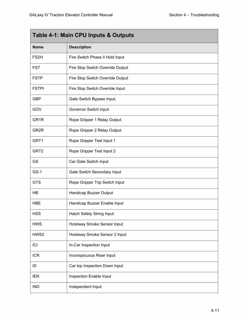
GALaxy IV Traction Elevator Controller Manual Section 4 – Troubleshooting
4-11
Table 4-1: Main CPU Inputs & Outputs
Name Description
FS2H Fire Switch Phase II Hold Input
FST Fire Stop Switch Override Output
FSTP Fire Stop Switch Override Output
FSTPI Fire Stop Switch Override Input
GBP Gate Switch Bypass Input.
GOV Governor Switch Input
GR1R Rope Gripper 1 Relay Output.
GR2R Rope Gripper 2 Relay Output.
GRT1 Rope Gripper Test Input 1
GRT2 Rope Gripper Test Input 2
GS Car Gate Switch Input
GS-1 Gate Switch Secondary Input
GTS Rope Gripper Trip Switch Input
HB Handicap Buzzer Output
HBE Handicap Buzzer Enable Input
HSS Hatch Safety String Input
HWS Hoistway Smoke Sensor Input
HWS2 Hoistway Smoke Sensor 2 Input
ICI In-Car Inspection Input
ICR Inconspicuous Riser Input
ID Car top Inspection Down Input
IEN Inspection Enable Input
IND Independent Input
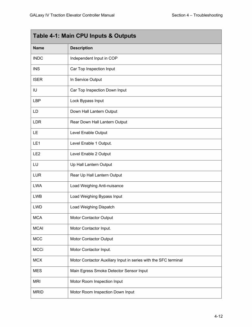
GALaxy IV Traction Elevator Controller Manual Section 4 – Troubleshooting
4-12
Table 4-1: Main CPU Inputs & Outputs
Name Description
INDC Independent Input in COP
INS Car Top Inspection Input
ISER In Service Output
IU Car Top Inspection Down Input
LBP Lock Bypass Input
LD Down Hall Lantern Output
LDR Rear Down Hall Lantern Output
LE Level Enable Output
LE1 Level Enable 1 Output.
LE2 Level Enable 2 Output
LU Up Hall Lantern Output
LUR Rear Up Hall Lantern Output
LWA Load Weighing Anti-nuisance
LWB Load Weighing Bypass Input
LWD Load Weighing Dispatch
MCA Motor Contactor Output
MCAI Motor Contactor Input.
MCC Motor Contactor Output
MCCi Motor Contactor Input.
MCX Motor Contactor Auxiliary Input in series with the SFC terminal
MES Main Egress Smoke Detector Sensor Input
MRI Motor Room Inspection Input
MRID Motor Room Inspection Down Input

GALaxy IV Traction Elevator Controller Manual Section 4 – Troubleshooting
4-13
Table 4-1: Main CPU Inputs & Outputs
Name Description
MRIE Motor Room Inspection Enable Input
MRIU Motor Room Inspection Up Input
MRS Motor Room Smoke Sensor Input
MRSW Motor Room Stop Switch
NBFB Nudging/Fire Buzzer Output
NTSD Normal Terminal SlowDown Initiation Output
NTSD1 Normal Terminal SlowDown 1 Secondary Initiation Output
NTSDi Normal Terminal SlowDown Initiation Input
NUD Door Nudging Output
NUDR Door Nudging Rear Output
OVL Overload Input
P Potential (Run Contactor) Input
P1-Pn 1ST – Nth Discrete Floor Position Indicator Outputs
PFC Primary Fault Control Output
PFCi Primary Fault Control Input
PS Pit Switch Input
RDY Drive Ready Input
RGS Rear Car Gate Switch Input
RGS-1 Rear Car Gate Switch Secondary Input
RLM Rear Lock Middle Input
RLM-1 Rear Lock Middle Secondary Input
RLS Rail Lock Switch Input
RST Reset Drive Output

GALaxy IV Traction Elevator Controller Manual Section 4 – Troubleshooting
4-14
Table 4-1: Main CPU Inputs & Outputs
Name Description
RTL Return to lobby Input
RUN Run Pilot Output
RUNAi Run Auxiliary Input
RUNi Run Input.
RUNX Run Auxiliary Relay Input (Hardware run signal to the drive)
S10 Controller Power Input
SE Safety Edge Input
SER Safety Edge Rear Input
SFCi Secondary Fault Control Input
TAD Top Access Down Input
TAU Top Access Up Input
TF Top Final Input
TPL Temp Low Input (Hydraulic Elevators)
UDA Up Direction Arrow Output
UFi Up Fast Input
UL Up Level Sensor Input
UL-1 Up Level Sensor Secondary Input
UN Up Normal Limit Input
UP Up Pilot Output
Upi Up Run Input
UT Up Terminal Limit Input
UT1-6 Up Terminal Input 1-6
UTS Up Emergency Terminal Slowdown Input

GALaxy IV Traction Elevator Controller Manual Section 4 – Troubleshooting
4-15
4.8 Safety Processor Inputs and Outputs
Table 4-2: Safety Processor Inputs & Outputs
Name Description
ACC Access. Input equals 1 when the car is on access operation.
AUTO Auto Input. Input equals 1 when the car is on automatic operation.
CTI Car Top Inspection. Input equals 1 when the car is on car top inspection.
DL‐1 Down Level Secondary Input. Input from the selector that the car is on the down level sensor in the door zone.
DLB‐1 Door Lock Bottom Secondary Input. Input equals 1 when the bottom door lock is made.
DLM‐1 Door Lock Middle Secondary Input. Input equals 1 when the middle door locks are made.
DLT‐1 Door Lock Top Secondary Input. Input equals 1 when the top door lock is made.
DNR Down Run Output. Output from the main CPU when the car is running down.
DT Down Terminal Slowdown. Input goes low when the car is on the down terminal slowdown limit.
DTS Down Emergency Terminal Slowdown. Input goes low when the car is on the down emergency terminal slowdown limit.
GBP Gate Bypass. This is the input from the gate bypass switch. 1 = bypass switch is on.
GS‐1 Gate Switch Secondary Input. Input equals 1 when the front door gate switch is made.
ICI In Car Inspection. Input equals 1 when the car is on in‐car inspection operation.
LBP Lock Bypass. This is the input from the lock bypass switch. 1 = bypass switch is on.
LSCS Leveling Speed Control. Output comes on when the car is traveling less than 150 fpm.
MRI Motor Room Inspection. Input equals 1 when the car is on motor room inspection.
RGS Rear Gate Switch. Input equals 1 when the rear door gate switch is made.
RLM‐1 Rear Lock Middle Input. Input equals 1 when the rear middle locks are made.
SFCO Safety Fault Control Output. Output must be on to energize the SFC relay. When this relay is dropped out, the safety string will be opened.

GALaxy IV Traction Elevator Controller Manual Section 4 – Troubleshooting
4-16
Table 4-2: Safety Processor Inputs & Outputs
Name Description
UL‐1 Up Level Secondary Input. Input from the selector that the car is on the up level sensor in the door zone.
UP Up Run Output. Output from the main CPU when the car is running up.
UT Up Terminal Slowdown. Input goes low when the car is on the up terminal slowdown limit.
UTS Up Emergency Terminal Slowdown. Input goes low when the car is on the up emergency terminal slowdown limit.
4.9 NTS Processor Inputs and Outputs
Table 4-3: NTS Processor Inputs & Outputs
Name Description
DN Down Normal Slowdown Input
DNR Down Run Input
DT Down Normal Terminal Slowdown Input
DT1-6 Down Normal Terminal Slowdown 1 - 6 Inputs
NTSD Normal Terminal Slowdown Initiation Output
NTSD1 Normal Terminal Slowdown 1 Secondary Initiation Output
UN Up Normal Slowdown Input
UP Up Run Input
UT Up Normal Terminal Slowdown Input
UT1-6 Up Normal Terminal Slowdown 1 - 6 Inputs
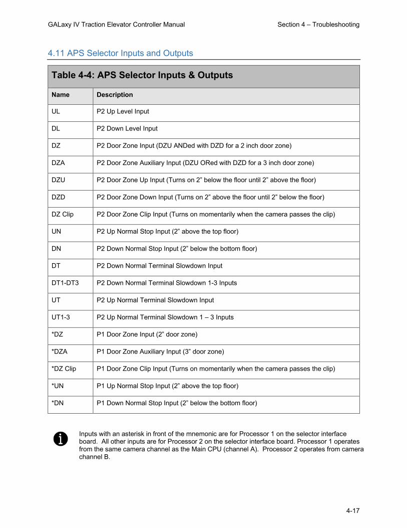
GALaxy IV Traction Elevator Controller Manual Section 4 – Troubleshooting
4-17
4.11 APS Selector Inputs and Outputs
Table 4-4: APS Selector Inputs & Outputs
Name Description
UL P2 Up Level Input
DL P2 Down Level Input
DZ P2 Door Zone Input (DZU ANDed with DZD for a 2 inch door zone)
DZA P2 Door Zone Auxiliary Input (DZU ORed with DZD for a 3 inch door zone)
DZU P2 Door Zone Up Input (Turns on 2” below the floor until 2” above the floor)
DZD P2 Door Zone Down Input (Turns on 2” above the floor until 2” below the floor)
DZ Clip P2 Door Zone Clip Input (Turns on momentarily when the camera passes the clip)
UN P2 Up Normal Stop Input (2” above the top floor)
DN P2 Down Normal Stop Input (2” below the bottom floor)
DT P2 Down Normal Terminal Slowdown Input
DT1-DT3 P2 Down Normal Terminal Slowdown 1-3 Inputs
UT P2 Up Normal Terminal Slowdown Input
UT1-3 P2 Up Normal Terminal Slowdown 1 – 3 Inputs
*DZ P1 Door Zone Input (2” door zone)
*DZA P1 Door Zone Auxiliary Input (3” door zone)
*DZ Clip P1 Door Zone Clip Input (Turns on momentarily when the camera passes the clip)
*UN P1 Up Normal Stop Input (2” above the top floor)
*DN P1 Down Normal Stop Input (2” below the bottom floor)
Inputs with an asterisk in front of the mnemonic are for Processor 1 on the selector interface board. All other inputs are for Processor 2 on the selector interface board. Processor 1 operates from the same camera channel as the Main CPU (channel A). Processor 2 operates from camera channel B.

GALaxy IV Traction Elevator Controller Manual Section 4 – Troubleshooting
4-18
4.12 Relocate I/Os
Special Relocation I/O’s are located on the Machine Room CAN bus, the Car Top CAN bus and the Group CAN bus. Each CAN bus has three inputs and three outputs for this purpose, and are named as follows:
MRCAN CTCAN GRCAN Inputs Outputs Inputs Outputs Inputs Outputs
MSPI1 MSPO1 CSPI1 CSPO1 GSPI1 GSPO1 MSPI1 MSPO2 CSPI2 CSPO2 GSPI2 GSPO2 MSPI3 MDPO3 CSPI3 CSPO3 GSPI3 GSPO3
Mnemonic legend: M (MRCAN) SP (Spare) I (Input) 1 C (CTCAN) SP (Spare) O (Output) 1 G (GRCAN) SP (Spare) I (Input) 3 The locations of these I/Os are preset in the io.dat file and can be viewed on the diagnostic I/O display or on the board electronic ink label.
To relocate the I/O, select the “Relocate I/O” menu from the “Inputs and Outputs” menu. Then select the “Add I/O Relocation”. Use the Up or Down button to select the input type and location such as CSPI1, (CTCAN car spare input 1). The type is an input and CSPI1 is located where the desired Input will be relocated. Hit the Enter button and then the Up or Down to select the I/O to be relocated. Only I/O’s allowed on the selected bus will be displayed. When you reach the I/O to be relocated, then hit the Enter button again. Once an I/O has been selected, power must be cycled on the controller for the relocation to take place.
To remove an individual I/O from the relocation table, select the “Remove I/O Relocation” menu and then “Select I/O: None” and hit enter. To remove all I/O relocations, select the “Clear Relocation Table” menu and hit enter. Please refer to the Inputs and Outputs menu of the LCD Interface section for a graphic view of the Relocate I/Os menu.
4.13 GALileo Enhanced Diagnostics
The GALaxy IV controller is equipped with the GALileo Enhanced Diagnostics feature that provides elevator personnel with diagnostic information on a machine room monitor or smart device. The GALileo Enhanced Diagnostics includes the following features.
• Group Screen • Fault Log • Car I/O Screen • Hall I/O Screen • Adjustable Variables • Trace Screen • Traffic Analysis • Event Scheduling • Service Settings • Call Lockouts • Fault Description List • PDF copies of Project Documents • Instructional Videos
The GALileo User’s Guide provides a complete description of the GALileo features.

GALaxy IV Traction Elevator Controller Manual Section 4 – Troubleshooting
4-19
4.13.1 GALileo Trace Screen
The “Trace Screen” feature allows elevator personnel to record the operation of the elevator over a period of time and replay this recorded information. This recorded event, provides detailed information to assist in adjustment and troubleshooting.
This feature requires v7.01.07 software or later and can be accessed from the machine room monitor or smart device.
The “Trace Screen” functions as follows:
When the controller powers up, it begins storing trace information at the preset time interval, usually 10 msec, but can be adjusted to 20, 30 or 40 msec. This means that data is recorded for 5 seconds duration and will continue to cycle until stopped by the F2 key or from a set trigger.
The trace stops storing data when a trigger condition occurs. The trace information is the same data that is stored for each fault occurrence but is stored in volatile memory, i.e. the data is lost when power is cycled. Even though the trace data is not stored in non-volatile memory, the trigger setup conditions is stored in non-volatile memory and will not be lost when power is cycled.
The playback commands from the machine room monitor are:
• F1 to re-start the trace • F2 to trigger a stop trace condition. When the trigger is activated the controller will store 35
more trace frames and then will stop. • The Home key places the count (frame) to the trigger point after the trace is stopped – start of
trigger. • The End key places the count to the last frame after the trace has stopped (i.e. 35 frames after
the trigger point) – end of trigger. • If you press the End key and then one Up arrow key, the frame will be at the start of the trace. • The Up and Down arrows increment or decrement the frame by one count • The Page Up and Page Down keys increment or decrement the frame by ten counts. • The Right and Left arrow keys scroll part of the status screen data at the bottom of the screen.
Using the GALileo interface, the playback commands are graphical, and allow you to step through the trace one frame at a time, 10 frames at a time, or move the slider to any position. To play the trace for the entire run use the play button.
The trace trigger and timing can be setup from the “Trace Setup” menu under “Software Utilities”. Below is a list of the trace setup menus and their functions:
• Stop Trace Recording • Start Trace Recording • Trace Time Interval – Time interval from 10 to 20, 30 or 40 msec. Extends the trace time
from 5 seconds to 10, 15 or 20 seconds respectively. • Trace Trigger Arm – Arm the trace for a condition after power up:
o Always Armed o Power Up Reset o Initial At Floor o Motion Start o Initial Stop, o Re-level Start o Front Door Open Start
o Front Door Dwell Start o Front Door Close Start o Rear Door Open Start o Rear Door Close Start o Rear Door Close Start o Inspection Start o Safety String Start
• Trace Trigger Window – Time window for logic events to be considered valid. When the trigger condition is set for more than one condition and a trigger condition occurs

GALaxy IV Traction Elevator Controller Manual Section 4 – Troubleshooting
4-20
momentarily, this is the duration of time that the momentary condition is considered valid. A value of 35 is recommended.
• Setup Trace Trigger – The logic condition for the trace trigger to occur. There is an “AND” trigger variable and an “OR” trigger variable. When a trigger condition is selected, the user must set it in the “AND” or “OR” trigger variable. A trigger condition cannot be set in both trigger variables. The trigger occurs when all the “AND” conditions are met or any of the “OR” conditions are met. In addition, the trigger ARM must also be active. Trigger conditions can be set from the following: o Fault change o Fault match o servf change o servf match o procf change o procf match o run_statusf change o run_statusf match o slowdown change o slowdown match o rear slowdown change o rear slowdown match o statusf change o statusf match o statusf2 change
o statusf2 match o Fault Bits 0 change o Fault Bits 0 match o Fault Bits 1 change o Fault Bits 1 match o Fault Bits 2 change o Fault Bits 2 match o Fault Bits 3 change o Fault Bits 3 match o SPB service change o SPB status change o SPB command change o NTS service change o NTS status change o NTS command change
• Show Trace Trigger Logic • Clear Trace Trigger Logic

GALaxy IV Traction Elevator Controller Manual Section 5 – LCD Interface
5-1
Section 5 – LCD Interface
5.1 Operating the LCD Interface
5.1.1 Interface Operator Panel
UP Button is used to scroll up to the next menu item, or increment data values.
DOWN Button is used to scroll down to the next menu item, or decrement data values.
MODE Button is used to go back to the previous menu, or select digits of data values.
ENTER Button is used to select menu items, or complete the operation of changing data values.
Potentiometer is used to adjust the viewing angle. It makes the display lighter or darker.
The LCD Interface Board uses a 2 line by 24-character display, and it includes four buttons for navigation and menu item selections (see above). This interface allows the user to adjust parameters, view critical controller information, implement controller setup options, and view elevator status information. Upon power-up, the interface board shows a blinking “GALaxy” on the display to indicate the controller is running, as shown in the photograph above.
The four buttons used for operating the LCD display are UP, DOWN, MODE, and ENTER. The UP and DOWN buttons are used to scroll up and down items listed for selection in the controller menus. The ENTER button is used to select a particular item. Some menu items, have submenus containing additional selection items. Again, in these submenus, the UP and DOWN buttons are used for scrolling through the items, and the ENTER button to is pressed to make selections.
The MODE button is used to return to previous menus.
When a menu item is an adjustable variable, the item is selected with the ENTER button, and the UP or DOWN buttons are used to adjust the item’s value. In number entries, the MODE button is used to move the cursor to the next digit. Once the appropriate value has been selected, the ENTER button is used to confirm/complete the variable change operation, and exit edit mode.
The following pages in this section provide descriptions of the flowcharts at the end of the chapter. The descriptions and flowcharts are shown separately, to allow more space for the graphics, for better readability.
For clarity and better organization, the descriptions are provided in the same order as the flowcharts.

GALaxy IV Traction Elevator Controller Manual Section 5 – LCD Interface
5-2
5.1.2 LCD Interface Main Menu
The flowchart for the Main Menu shows the top-level menus in the controller system.
5.1.3 Elevator Status
The Elevator Status Display continuously updates to show the current status and fault information regarding the elevator. The UP and DOWN keys allow access to both the status display and the velocity display. When a system fault occurs, it will be shown on the top line of the status display while the fault exists, and it will remain displayed for 60 seconds after the fault is cleared. The following six categories of status information (including fault information) may appear on this screen:
Elevator Service: Out of Service Automatic Service Independent Service Load Weighing By Pass Attendant Service Code Blue Service Fire Service Phase 2 Emergency Power Service Earth Quake Service Fire Phase 1 Main Return
Fire Phase 1 Alt Return Homing Reset Going Up Reset Going Down Stalled Out of Service Return to Lobby Load Weighing Overload Medical Emergency Serv. Calibrate Load Weigher Car Switch Elevator Off
Hall Switch Elevator Off Low Pressure Hospital Service Priority Service Security Recall Sabbath Service TUG Service Hot Oil Operation Riot Control
Elevator Status: Reset Mode Inspection Mode Up Fast Up Transition Leveling Up Down Fast Down Transition Leveling Down Soft Start Mode
Constant Accel Roll Over Max Vel Constant Velocity Roll Over Deccel Constant Deccel Targeting Floor Emergency Slowdown Safety String Open Elevator Off Line
Elevator Parked Waiting Assignment Door Procedure Elevator Stalled Reset Hydro Jack Low Pressure Mode Auto Learn HW Mode Emp Recovery Mode Hot Oil Mode
Door Status: Elev Door Closed Elev Door Opening Elev Door Dwelling Elev Door Open Elev Door Closing Elev Door Nudging F1RET Door Open F2CPO Door Open
F2CPO Door Opening F2CPO Door Closed F2CPO Door Closing F2CPC Door Open F2CPC Door Opening F2CPC Door Closed F2CPC Door Closing F2HLD Door Open
F2HLD Door Opening F2HLD Door Closed F2HLD Door Closing F2MBC Door Open F2MBC Door Opening F2MBC Door Closed F2MBC Door Closing
Rear Door Status: Rear Door Closed Rear Door Opening Rear Door Dwelling Rear Door Open Rear Door Closing Rear Door Nudging F1RET RDor Open F2CPO RDor Open
F2CPO RDor Opening F2CPO RDor Closed F2CPO RDor Closing F2CPC RDor Open F2CPC RDor Opening F2CPC RDor Closed F2CPC RDor Closing F2HLD RDor Open
F2HLD RDor Opening F2HLD RDor Closed F2HLD RDor Closing F2MBC RDor Open F2MBC RDor Opening F2MBC RDor Closed F2MBC RDor Closing

GALaxy IV Traction Elevator Controller Manual Section 5 – LCD Interface
5-3
High Priority Elevator Status: S10 Input Off HC Input Off SS Input Off READY Input Off Gripper/EBK Fault I/O Error Insp or Byp Error Bin. Pos. Error Position Error AD Input Off CS Input Off Door Zone Fault Gate/Lock Fault P Input On Looking for DCL Door Close Contact Brake Switch Fault TOC CAN Com Error DRIVE Com Error Saf Proc Com Error DB Res. Temp. Trip
Run Fault: Shutdown Annual Safety Test Waiting for SAFE Terminal Limit Flt GTS Input Off UL, DL, DZ Off at FL Brake CAN Error Fire Stop Sw. Off SEL CAN Com Error UL or DL Fault Leveling Fault Hardware Init Flt Front Door Cls Flt Rear Door Clos Flt Line Voltage Fault Door Voltage Fault BK Lift Sw Run Flt Door Motor OVL Learn Hoistway Flt UPS Fault Em Brake CAN Error
KEB Drv Not In Run At Floor Shutdown 1036 Auto Run Hold Reset Run Failure Invalid SEL count COP can comm error Encoder can comm error IO Test in progress Gripper Test in progress No Power to Drive Non Interference timer Door open request Waiting for DPM Waiting for RPM Viscosity operation Leveling request Terminal Limit Speed Clamp Sped Rate Clamp Front EE Test failed fault Rear EE Test failed fault Setup Mode No Auto
Fault Status: See the CPU FAULTS Section
5.1.4 Set Calls and Lockouts
When a car is in a group, the menu system allows access to options for setting both hall calls and car calls. When the controller is not the group, only car calls can be set. Rear car calls and lockouts are displayed only when the car has a rear door.
5.1.5 Car Call Test
This menu allows elevator personnel to initiate a continuous test of the elevator. The test can be conducted with the AUTO DOORS switch set to ON or OFF. The Car Call Test can be initiated or discontinued by following the instructions in the menu. When performing the Car Call Test, the car will answer all registered calls in one direction. When the last call has been answered for this direction, the calls will be automatically re-initiated and the car will begin to answer calls in the opposite direction. This operation will continue until one of the following situations occurs.
• The test is discontinued from the LCD interface. • The car is taken out of automatic operation. • A fault occurs in the system.
The car will not perform the Car Call Test if it is on Independent Service Mode.
When performing the Car Call Test with the AUTO DOORS switch set to OFF, it is recommended to set the NON-INTERFERENCE TIME to at least 5 seconds. From the LCD interface, navigate to Adjustable Variables => Car Timers, and then set NON INTERFER T = 5.

GALaxy IV Traction Elevator Controller Manual Section 5 – LCD Interface
5-4
5.1.6 Inputs & Outputs
Inputs and outputs are shown as a “1” for ON and a “0” for OFF. A list of all inputs and outputs used on the controller, and on specific boards, is shown in Section 4 of this manual, “Troubleshooting”. The controller determines which boards are used, depending on the options selected and the number of front and rear floors specified by the configuration files. The Input and Output Menu has submenus to access the car, group, Safety Processor, and NTS Processor I/Os. All I/O locations are determined from an io.dat file on the SD Card. I/Os in lines 0-13 and 138-146 of the io.dat file are specific hardware dependent locations, and their table locations should never be changed.
5.1.7 Job Statistics
Job Statistics:
The Job Statistics Menu shows the number car calls and the number and percent of hall calls serviced since the job was started, or since the job statistics were cleared. Listed on the right are all the call categories maintained:
• Number of Car Calls • Number of Up Hall Calls • Number of Down Hall Calls • Number of Up Hall Calls with < 15 second wait time • Number of Up Hall Calls with < 30 second wait time • Number of Up Hall Calls with < 45 second wait time • Number of Up Hall Calls with < 60 second wait time • Number of Up Hall Calls with > 60 second wait time • Number of Down Hall Calls with < 15 second wait time • Number of Down Hall Calls with < 30 second wait time • Number of Down Hall Calls with < 45 second wait time • Number of Down Hall Calls with < 60 second wait time • Number of Down Hall Calls with > 60 second wait time • Percent of Hall Calls with < 15 second wait time • Percent of Hall Calls with < 30 second wait time • Percent of Hall Calls with < 45 second wait time • Percent of Hall Calls with < 60 second wait time • Percent of Hall Calls with > 60 second wait time
5.1.8 Adjustable Variables
The Adjustable Variables Menu allows modification of all field adjustable parameters for the Main CPU, the Safety Processor, and the NTS Processor. Refer to the Adjustable Variables section of this manual for a list of all parameters and their functions.
5.1.9 Car Timers
This is an example of an Adjustable Variables Submenu. Other Adjustable Variable submenus will be similar.
5.1.10 Date and Time
It is important to set the date and time on the controller clock, so that the fault log shows the correct time stamp and sequence as faults occur.

GALaxy IV Traction Elevator Controller Manual Section 5 – LCD Interface
5-5
5.1.11 Diagnostics
The Diagnostics Menu shows the communications status for all serial devices. For most of these devices, the firmware version and the transmit/receive counts are displayed. The transmit/receive counts should be incrementing continuously for all serial devices while the device is communicating. All CAN bus communications ports show TxErr and RxErr counts, which ideally should show as zero. A non-zero error count on a CAN channel, or a non-incrementing receive counter on any serial channel, indicates a poor cable connection, or the presence of electrical noise on the cable. The Diagnostics Menu also contains a VIEW SYSTEM STATUS display that logs changes in elevator faults, status, and service.
The following is a list of all submenus of Diagnostics that are useful for troubleshooting status and communications issues within the system.
Boards, systems, and other controllers can be checked here for proper communications (On-Line) and for referencing firmware versions. These submenus are as follows:
• View System Status Log • Group Comm Status • Group CAN Comm Status • Car CAN Comm Status
• Machine Room CAN Comm Status • Safety CAN Comm Status • Drive Comm Status
5.1.12 Software Utilities
The Software Utilities Menu allows the user to view the controller’s software version, run Power-Up Mode, test the CPU watchdog timer, access SD Card operations, and to preset all limit velocity values.
View Software Version: Display the software version, revision and interim revision in the form 7.00.31.
Run Power-Up Mode: The Power-Up Mode is a program that executes first upon power up of the controller. It checks that there is a valid controller program in memory, and that a valid cons.dat file is on the SD Card. Once this is validated, the power up program runs the controller program. If the power up program is executed from the controller program, or if during power up, the user presses and holds the ENTER and MODE buttons. This routine does not run the controller program but stays in the power up routine, to allow for updates of the controller program. The Power-Up Mode is also used to upload new controller software from the SD Card to the Main CPU, the Safety Processor, and the NTS Processor.
Test Watchdog Reset: The watchdog is a CPU timer whose software must be updated periodically to confirm that the Main CPU program is still running correctly. If the watchdog is not updated, the timer will expire and cause the Main CPU to do a hard reset, to allow the program to restart. To test the watchdog timer, when the command is given, the controller program sits in an infinite software loop without updating the watchdog time to test that the reset function works.
Reset Debug Variables: The debug variables are set by a software engineer to aid in debugging a software problem. Some problems are especially difficult to catch because they occur infrequently or at random. The debug variables are displayed in the detailed Elevator Status Menu so that elevator personnel can view the variables and report back to the software engineer. The Reset Debug Variables menu allows elevator personnel to reset the variables to zero, to aid in the debugging.
SD Card Read/Write Data: This menu item allows the user to read and write controller data to and from the SD Card. This menu is explained in detail in the next section.
SD Card Status: This is the Secured Digital Card Status that shows if the card has been initialized (Init=1), if it is standard (HC=0) or High Capacity (HC=1), and if it can operate at an acceptable voltage level (VStat=1).

GALaxy IV Traction Elevator Controller Manual Section 5 – LCD Interface
5-6
5.1.13 Power-Up Mode
When the Main CPU powers up, it runs a power-up routine that verifies the checksum of the controller program in local flash memory, and then verifies that the job configuration file is on the SD Card. If the checksum and job configuration file are okay, the power-up routine jumps to the controller program. If the power up does not pass these verifications however, the program control stays in the power-up routine and the elevator is not allowed to run. To enter power-mode (run the power-up routine), cycle the power while pressing the ENTER and MODE buttons on the LCD Display Interface, and then release the button when the display indicates to do so. Alternately, power up mode can also be entered by placing the car on inspection and selecting the Run Power-Up Mode Submenu item located in the Software Utilities Menu.
5.1.14 Update / Verify Program
This menu is used to check the integrity of the CONS file, the controller program, and the SD card itself. The Update/Verify Program Menu is also used to update the controller software. Whenever the software is to be updated, the controller must be booted without an SDCard, and when the Power-Up Mode Screen appears, the SD card can be inserted, the software can then be updated through entering Update/Verify Program => Load Program from SDCard Submenu.
5.1.15 Select Video Display
This menu allows you to select different video display screens when a machine room monitor is installed on the controller. If the monitor is installed on a non-dispatcher car, then only information for that car is displayed on the monitor.
5.1.16 Service Activation Timers
All services have either an input that triggers them or a condition that activates them. The Service Activation Timers could be used in addition to these inputs. The timers will allow a feature to be turned on during specific times of the day, without the need of a specific condition or switch operation. All GALaxy traction and complex hydro controllers have service activation timers built in. Up to ten different timers (TIMER0 to TIMER9) can be programmed.
The timers listed below will turn on services that will run only during predefined times set by elevator users. At this moment, there are fourteen such services:
Parking Alternate Parking Next Up Up Peak Down Peak
Alternate Lobby Alternate Floor Security Car Call Lockouts Group Car Call Lockouts Car Call Override
Group Car Call Override Sabbath CC Push Button Security Floor Security Table 2- 4
There are two types of time settings that can be used to determine when the timers will run:
() Day of the Week: This will allow you to turn services ON and OFF for each individual day of the week. This is a total of seven ON and OFF time settings.
() Month and Day: This will allow services to run only on the date on which they are set. There are three on and off settings for this type.
The Day of the Week setting will be the most common setting for most service timers. However, Month and Day timers can be useful for programming special events or holidays. Setting the Day of the Week timer makes the selected service run repeatedly every day. Month and Day timers will run only once a year.

GALaxy IV Traction Elevator Controller Manual Section 5 – LCD Interface
5-7
Programming the timers can be done through the LCD interface or the Galileo Interface. Once the timers are programmed, you could disable or enable the timer without modifying any of the settings. In other words, a timer could be programmed completely, and stay disabled until the building is ready for implementation. At that point you would simply turn it on.
5.1.17 Display Hoistway Table
This menu is useful for checking the encoder direction by watching the encoder for the direction of the pulse counts. Once the hoistway is learned, the pulse count values for each floor will be displayed. If the pulse count for each floor is zero (does not increase or decrease), the hoistway has not been learned or the floor counts have not been retained in memory. The velocity displayed is the speed of the car as read from the car’s position feedback system. The top line shows current pulse count which can be compared to the stored pulse count. The second line are the learned values.
Note that the first landing should have a higher pulse and distance count than the DN values, i.e. DN 0.0, first landing 0.1 (second line on the right). It is possible to adjust the pulse count slightly, but it is recommended that the magnets be moved and the hoistway relearned.
5.1.18 DZ & DZ Offset, Sel Cnt
This menu provides status information when using a CAN open encoder. It also allows the elevator personnel to adjust the DN LEV DIST and UP LEV DIST parameters in order to “fine tune” the floor levels after the car is running high speed. These parameters are valid when the STOP ON POS adjustable variable is enabled. Refer to the “Fine Tune The Ride Quality” in sections 3 for proper adjustment.
5.1.19 FL & FL Offset Count
This menu allows elevator personnel to adjust the stored floor count for each floor level. It also allows offsets to be used to “fine tune” the floor levels after the car is running high speed. The FLOOR LEVEL OFFSET is valid when the STOP ON POS adjustable variable is enabled in Adjustable Variables => Car Motion. Refer to the “Fine Tune The Ride Quality” in Section 3 for proper adjustment.
5.1.20 Reset Update Count Trig, Pulse Count Update Data
This menu is valid when the POS COUNT UPD variable is enabled in Adjustable Variables => Car Motion. When this variable is enabled, the DP count will be updated while the car is in motion. The Pulse Count Update Data Menu provides detailed information in order to properly set this variable. The Reset Update Count Trig Menu allows the elevator personnel to manually reset the “Update Trigger”.
5.1.21 Elevator Setup
From this menu, the user can select to set all the speed clamps, learn the hoistway, run an overspeed test, run a car buffer test or run a counterweight buffer test, open and close the doors on inspection and setup the load weigher.
5.1.22 Match Feedback Velocity & Direction
This operation is part of the setup procedure of the elevator to match the velocity and direction of the three main control CPUs, the Main CPU, Safety Processor and NTS Processor. The mechanic is instructed to run the car up on Machine Room Inspection. While the car is running up, the Main CPU will monitor the speed and direction of all three devices and make the appropriate parameter changes to correct for any differences. Note that the Main CPU will indicate to release the inspection run in order to update parameters for the NTS or SPB processors. If the velocity or direction cannot be corrected, the Main CPU will display status information so the mechanic can make the necessary correction.

GALaxy IV Traction Elevator Controller Manual Section 5 – LCD Interface
5-8
5.1.23 Auto Learn Hoistway
This operation is used to automatically learn the hoistway on initial setup. From the LCD Interface, select the Elevator Setup Menu, use the up or down button to select the Learn Hoistway item, and then press ENTER. Follow the directions displayed for each step. Learn Hoistway can be initiated with the car located anywhere in the hoistway but is usually best to run the car to the bottom first.
5.1.24 Inspection Learn Hoistway
This operation is used to manually learn the hoistway on initial setup. From the LCD Interface, select the Elevator Setup Menu, use the UP or DOWN button to select the Learn Hoistway item, and then press ENTER. Follow the directions displayed for each step. Learn Hoistway can be initiated with the car located anywhere in the hoistway, but is usually best to run the car to the bottom first.
5.1.25 Learn Limit Velocities
This operation is used to setup the clamp values or trip velocities for the Main CPU, Safety Processor, and NTS Processor for the appropriate terminal limits. From the LCD Interface, select the Elevator Setup Menu, use the UP or DOWN button to select the Learn Limit Velocities item, and then press ENTER. Follow the directions displayed for each step. The Learn Limit Velocities procedure should be run only after the ride of the car is adjusted (acceleration and decelerations are set as desired).
5.1.26 Manually Setting Main CPU Speed Clamps
Once the car is running on Automatic Mode, the acceleration and deceleration rates are adjusted, and several runs have been made from the top to the bottom terminals at contract speed, the speed clamps can then be adjusted. Using the set speed clamp menus on the LCD interface, select the clamp to adjust and press ENTER to access the clamp setting. In the above illustration, the suggested setting is shown as the CLAMP SPEED and the actual clamp setting is shown as INS/ LEVEL SPD. The ENTER button is used to enter and exit the Edit Mode. Once in the Edit Mode, the MODE button selects the next digit to edit. The up and down buttons increment or decrement the clamp speed setting. All speed clamps are adjusted in the same manor. The speed clamps that can be adjusted are the inspection/leveling speed clamps, the Down and Up Terminal Slowdown speed clamps (DT/UT, DT1/UT1, DT2/UT2 and DT3/UT3) and the Down and Up Emergency Terminal Speed clamp (DTS/UTS).
See diagram for Elevator Setup for an example.
5.1.27 Inspection Open – Close Door
The menu allows elevator personnel to open or close the elevator doors from the up or down LCD interface buttons, while the car is on Inspection Mode.
5.1.28 Lift Brake on Inspection
The flowchart describes the steps for lifting the brake on inspection. WARNING: Brake will lift automatically during this test. Make sure all safety procedures are observed.
5.1.29 Loadweigher Setup
The loadweigher hardware is setup according to the manufacturer’s instructions. The controller is then setup to read the empty and full load values at every floor.
5.1.30 Load Weigher View/Modify
In this menu the load limits can be modified.

GALaxy IV Traction Elevator Controller Manual Section 5 – LCD Interface
5-9
5.1.31 Calibrate Load Weigher
This is the procedure for calibrating the loadweigher.
5.1.32 Counterweight & Buffer Test
The car and counterweight buffer test follow the same menu operation. For specific instruction on executing a buffer test, refer to Appendix B.
5.1.33 Overspeed Test
The overspeed test disables the velocity check for the car traveling faster than 15% over contract speed. The mechanism is disabled for one run. See Appendix B for instruction on running an overspeed test.
5.1.34 Reset / View Faults
This menu allows the user to view or clear the fault log.
5.1.35 View Fault Log
The fault display shows the fault, the car position, time and date the fault occurred and the number of occurrences. Faults are displayed in the order of occurrence with the order number displayed on the top left. The largest order number signifies the last fault that has occurred. Faults are stored in a circular buffer that fits up to 50 faults. Once the buffer is full the next fault overwrites the oldest fault (lowest numbered fault). Refer to the system faults in the troubleshooting section of this manual for possible causes of the fault and a description of the detailed fault data.
5.1.36 Clear Fault Log
This operation clears the fault log. Once cleared, all faults will show “No Occurrences” until a new fault occurs.
5.1.37 Reset Gripper Menu
This shows the procedure for resetting a Gripper fault

GALaxy IV Traction Elevator Controller Manual Section 5 – LCD Interface
5-10
5.2 LCD Menu Diagrams
5.2.1 Main Menu
Figure 5-1: The Main Menu of the LCD Interface
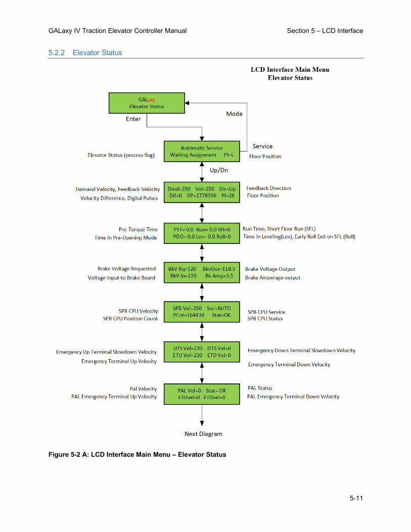
GALaxy IV Traction Elevator Controller Manual Section 5 – LCD Interface
5-11
5.2.2 Elevator Status
Figure 5-2 A: LCD Interface Main Menu – Elevator Status

GALaxy IV Traction Elevator Controller Manual Section 5 – LCD Interface
5-12
Figure 5-2 B: LCD Interface Main Menu – Elevator Status

GALaxy IV Traction Elevator Controller Manual Section 5 – LCD Interface
5-13
Figure 5-2 C: LCD Interface Main Menu – Elevator Status

GALaxy IV Traction Elevator Controller Manual Section 5 – LCD Interface
5-14
5.2.3 Set Calls and Lockouts
Figure 5-2: Figure 5-3: LCD Interface Main Menu – Set Calls & Lock Outs

GALaxy IV Traction Elevator Controller Manual Section 5 – LCD Interface
5-15
5.2.4 Car Call Test
Figure 5-4: LCD Interface – Car Call Test Submenu

GALaxy IV Traction Elevator Controller Manual Section 5 – LCD Interface
5-16
5.2.5 Lockout Front Car Calls
Figure 5-5: LCD Interface – Lockout Front Car Calls Submenu

GALaxy IV Traction Elevator Controller Manual Section 5 – LCD Interface
5-17
5.2.6 Inputs and Outputs
Figure 5-6: LCD Interface Main Menu – Inputs & Outputs

GALaxy IV Traction Elevator Controller Manual Section 5 – LCD Interface
5-18
5.2.7 Relocate I/Os
Figure 5-7: LCD Interface Main Menu – Relocate I/Os
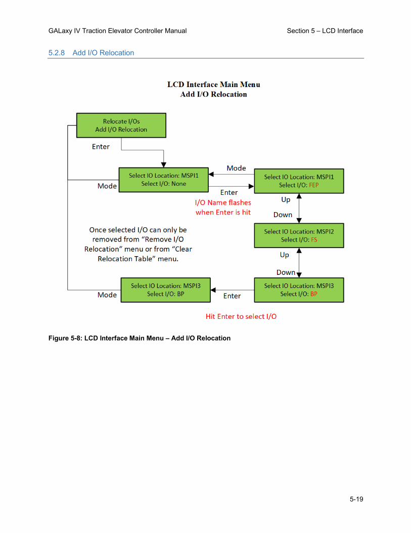
GALaxy IV Traction Elevator Controller Manual Section 5 – LCD Interface
5-19
5.2.8 Add I/O Relocation
Figure 5-8: LCD Interface Main Menu – Add I/O Relocation

GALaxy IV Traction Elevator Controller Manual Section 5 – LCD Interface
5-20
5.2.9 Job Statistics
Figure 5-9: LCD Interface Main Menu – Job Statistics

GALaxy IV Traction Elevator Controller Manual Section 5 – LCD Interface
5-21
5.2.10 Adjustable Variables
Figure 5-10: LCD Interface Main Menu – Adjustable Variables

GALaxy IV Traction Elevator Controller Manual Section 5 – LCD Interface
5-22
5.2.11 Car Timers
Figure 5-11: LCD Interface – Car Timers Submenu

GALaxy IV Traction Elevator Controller Manual Section 5 – LCD Interface
5-23
5.2.12 Date and Time
Figure 5-12: LCD Interface Main Menu – Date & Time
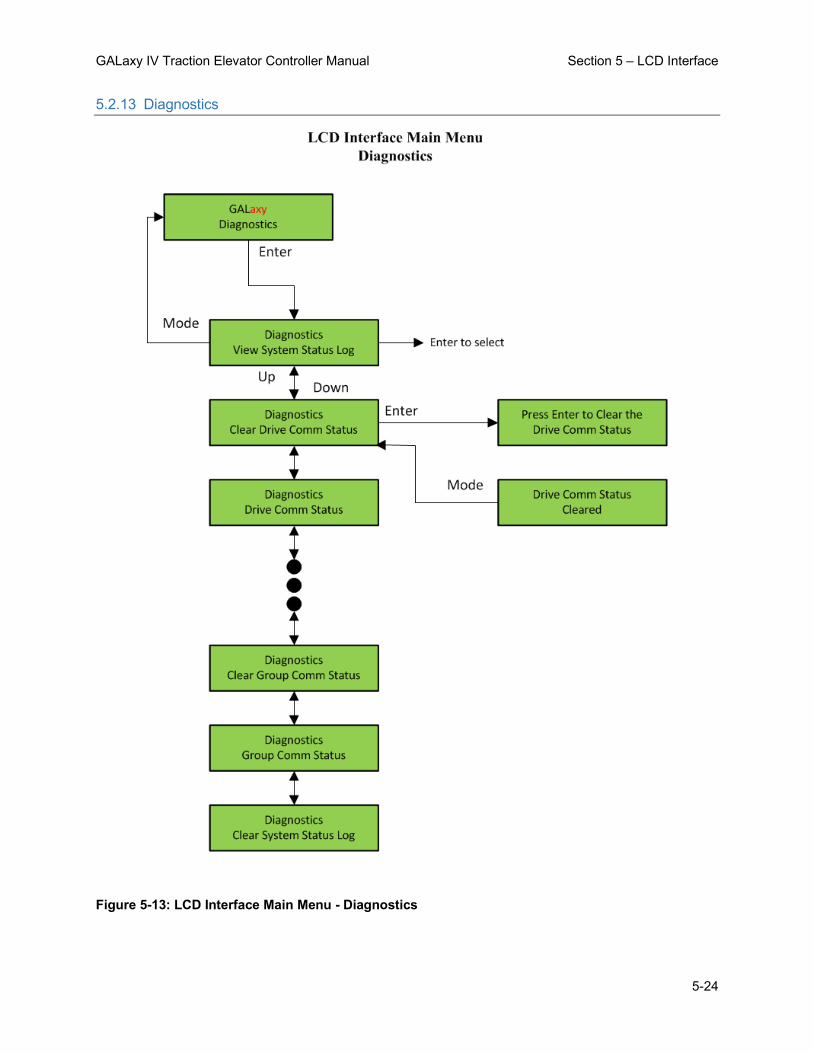
GALaxy IV Traction Elevator Controller Manual Section 5 – LCD Interface
5-24
5.2.13 Diagnostics
Figure 5-13: LCD Interface Main Menu - Diagnostics

GALaxy IV Traction Elevator Controller Manual Section 5 – LCD Interface
5-25
5.2.14 View System Status Log
Figure 5-14: LCD Interface – View System Status Log Submenu

GALaxy IV Traction Elevator Controller Manual Section 5 – LCD Interface
5-26
5.2.15 Group Comm Status
Figure 5-15: LCD Interface – Group Comm Status Submenu

GALaxy IV Traction Elevator Controller Manual Section 5 – LCD Interface
5-27
5.2.16 Group Can Comm Status
Figure 5-16: LCD Interface – Group Can Comm Status Submenu
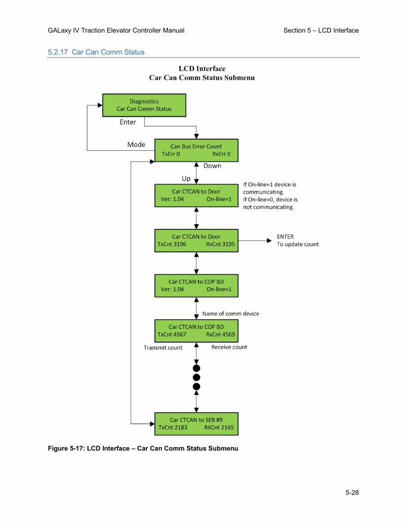
GALaxy IV Traction Elevator Controller Manual Section 5 – LCD Interface
5-28
5.2.17 Car Can Comm Status
Figure 5-17: LCD Interface – Car Can Comm Status Submenu

GALaxy IV Traction Elevator Controller Manual Section 5 – LCD Interface
5-29
5.2.18 Machine Room Can Comm Status
Figure 5-18: LCD Interface – Machine Room Can Comm Status Submenu
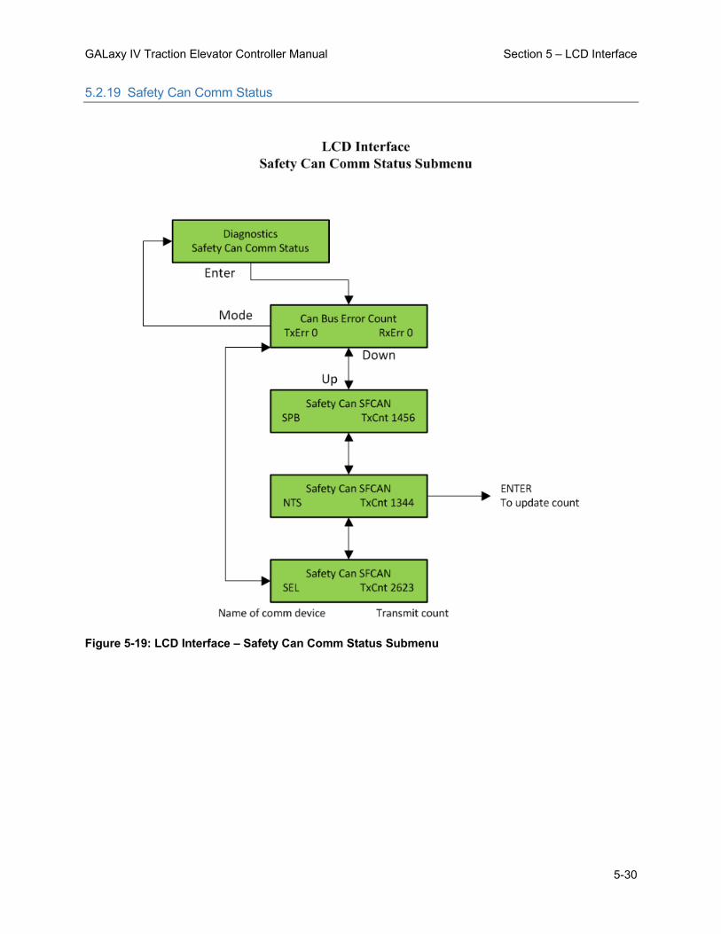
GALaxy IV Traction Elevator Controller Manual Section 5 – LCD Interface
5-30
5.2.19 Safety Can Comm Status
Figure 5-19: LCD Interface – Safety Can Comm Status Submenu

GALaxy IV Traction Elevator Controller Manual Section 5 – LCD Interface
5-31
5.2.20 Drive Comm Status
Figure 5-20: LCD Interface – Drive Comm Status Submenu

GALaxy IV Traction Elevator Controller Manual Section 5 – LCD Interface
5-32
5.2.21 APS CAN Comm Status
Figure 5-21: LCD Interface – APS Sel. Can. Comm. Status Submenu

GALaxy IV Traction Elevator Controller Manual Section 5 – LCD Interface
5-33
5.2.22 Software Utilities
Figure 5-22: LCD Interface Main Menu – Software Utilities

GALaxy IV Traction Elevator Controller Manual Section 5 – LCD Interface
5-34
5.2.23 Power-Up Mode
Figure 5-23: LCD Interface – Power-Up Mode

GALaxy IV Traction Elevator Controller Manual Section 5 – LCD Interface
5-35
5.2.24 Power-Up Mode –> Update / Verify Program
Figure 5-2423: LCD Interface – Update / Verify Program Submenu

GALaxy IV Traction Elevator Controller Manual Section 5 – LCD Interface
5-36
5.2.25 SD Card Read / Write Data
Figure 5-25: LCD Interface – SD Card Read / Write Data Submenu

GALaxy IV Traction Elevator Controller Manual Section 5 – LCD Interface
5-37
5.2.26 Network Card Setup
Figure 5-26: LCD Interface Main Menu – Network card Setup

GALaxy IV Traction Elevator Controller Manual Section 5 – LCD Interface
5-38
5.2.27 Preset Limit Velocities
Figure 5-27: LCD Interface Main Menu – Preset Limit Velocities

GALaxy IV Traction Elevator Controller Manual Section 5 – LCD Interface
5-39
5.2.28 Trace Setup
Figure 5-28: LCD Interface Main Menu – Trace Setup

GALaxy IV Traction Elevator Controller Manual Section 5 – LCD Interface
5-40
5.2.29 Send Floor Table to APS
Figure 5-29: LCD Interface – Send Floor Table to APS

GALaxy IV Traction Elevator Controller Manual Section 5 – LCD Interface
5-41
5.2.30 Select Video Display
Figure 5-30: LCD Interface Main Menu – Select Video Display

GALaxy IV Traction Elevator Controller Manual Section 5 – LCD Interface
5-42
5.2.31 Service Activation Timer
Figure 5-31: LCD Interface Main Menu – Service Activation Timer

GALaxy IV Traction Elevator Controller Manual Section 5 – LCD Interface
5-43
5.2.32 Set Month/Day Timers
Figure 5-32: Service Activation Timer Submenu – Set Month/Day Timers

GALaxy IV Traction Elevator Controller Manual Section 5 – LCD Interface
5-44
5.2.33 Clear Timers
Figure 5-33: Service Activation Timer Submenu – Clear Timers

GALaxy IV Traction Elevator Controller Manual Section 5 – LCD Interface
5-45
5.2.34 Copy Day of Week Timers
Figure 5-34: Service Activation Timer Submenu – Copy Day-of-Week Timers

GALaxy IV Traction Elevator Controller Manual Section 5 – LCD Interface
5-46
5.2.35 View / Modify Timer Status
Figure 5-35: Service Activation Timer Submenu – View / Modify Timer Status
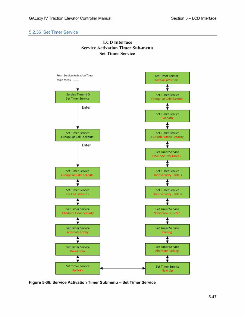
GALaxy IV Traction Elevator Controller Manual Section 5 – LCD Interface
5-47
5.2.36 Set Timer Service
Figure 5-36: Service Activation Timer Submenu – Set Timer Service

GALaxy IV Traction Elevator Controller Manual Section 5 – LCD Interface
5-48
5.2.37 Set Day of Week Timers
Figure 5-37: Service Activation Timer Submenu – Set Day-of-Week Timers

GALaxy IV Traction Elevator Controller Manual Section 5 – LCD Interface
5-49
5.2.38 Display/Modify Hoistway Tables
Figure 5-24: Hoistway Tables – Disp. / Mod. Hoistway Tables Submenu

GALaxy IV Traction Elevator Controller Manual Section 5 – LCD Interface
5-50
5.2.39 DZ & DZ Offset, Selector Count
Figure 5-39: Hoistway Tables – DZ & DZ Offset, Sel. Cnt. Submenu

GALaxy IV Traction Elevator Controller Manual Section 5 – LCD Interface
5-51
5.2.40 FL & FL Offset Count
Figure 5-40: Hoistway Tables FL & FL Offset, Sel. Cnt. Submenu

GALaxy IV Traction Elevator Controller Manual Section 5 – LCD Interface
5-52
5.2.41 Reset Update Count, Pulse Count Update
Figure 5-41: Hoistway Tables – Reset Update Count Trig. / Pulse Count Update Data Submenu

GALaxy IV Traction Elevator Controller Manual Section 5 – LCD Interface
5-53
5.2.42 Elevator Setup
Figure 5-25: LCD Interface Main Menu – Elevator Setup

GALaxy IV Traction Elevator Controller Manual Section 5 – LCD Interface
5-54
5.2.43 Match Feedback Velocity & Direction
Figure 5-43: LCD Interface Main Menu – Match Feedback Velocity & Direction
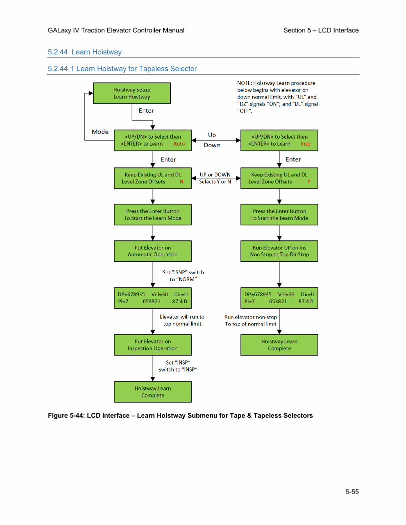
GALaxy IV Traction Elevator Controller Manual Section 5 – LCD Interface
5-55
5.2.44 Learn Hoistway
5.2.44.1 Learn Hoistway for Tapeless Selector
Figure 5-44: LCD Interface – Learn Hoistway Submenu for Tape & Tapeless Selectors

GALaxy IV Traction Elevator Controller Manual Section 5 – LCD Interface
5-56
5.2.44.2 Learn Hoistway for APS Selector
Figure 5-45: LCD Interface – Learn Hoistway Submenu for APS Selectors (Page i)

GALaxy IV Traction Elevator Controller Manual Section 5 – LCD Interface
5-57
Figure 5-46: LCD Interface – Learn Hoistway Submenu for APS Selectors (Page ii)

GALaxy IV Traction Elevator Controller Manual Section 5 – LCD Interface
5-58
5.2.45 Learn Limit Velocities
Figure 5-4726: LCD Interface – Learn Limit Velocities Submenu

GALaxy IV Traction Elevator Controller Manual Section 5 – LCD Interface
5-59
5.2.46 Open / Close Door
Figure 5-48: LCD Interface – Open / Close Front Door & Rear Door Submenus
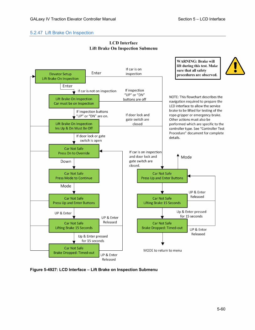
GALaxy IV Traction Elevator Controller Manual Section 5 – LCD Interface
5-60
5.2.47 Lift Brake On Inspection
Figure 5-4927: LCD Interface – Lift Brake on Inspection Submenu

GALaxy IV Traction Elevator Controller Manual Section 5 – LCD Interface
5-61
5.2.48 Load Weigher Setup
5.2.48.1 Setup Load Weigher
Figure 5-50: LCD Interface – Load Weigher Setup Submenu

GALaxy IV Traction Elevator Controller Manual Section 5 – LCD Interface
5-62
5.2.48.2 View/Modify Load Limits
Figure 5-51: LCD Interface – Load Weigher View / Modify Load Limits Submenu

GALaxy IV Traction Elevator Controller Manual Section 5 – LCD Interface
5-63
5.2.48.3 Calibrate Load Weigher
Figure 5-52: LCD Interface – Calibrate Load Weigher Setup Submenu

GALaxy IV Traction Elevator Controller Manual Section 5 – LCD Interface
5-64
5.2.49 Car Buffer Test
Figure 5-53: LCD Interface – Car Buffer Test Submenu

GALaxy IV Traction Elevator Controller Manual Section 5 – LCD Interface
5-65
5.2.50 Overspeed Test
Figure 5-54: LCD Interface – Overspeed Test Submenu

GALaxy IV Traction Elevator Controller Manual Section 5 – LCD Interface
5-66
5.2.51 Reset / View Faults
Figure 5-55: LCD Interface Main Menu – Fault Log

GALaxy IV Traction Elevator Controller Manual Section 5 – LCD Interface
5-67
5.2.52 Reset Gripper / EBK Fault
Figure 5-56: LCD Interface – Reset Gripper Fault Submenu

GALaxy IV Traction Elevator Controller Manual Section 6 – System Faults & Detailed Faults
6-1
Section 6 – System Faults & Detailed Faults
6.1 System Faults
Fault Description Possible Cause/Suggested Fix
Address Error Safety Processor has an Invalid Address
Program Error
Adv PreTrq Start Flt Did not get safe on advance pre-torque start
• Advance pre-torque is enabled. When pre-torque is activated, the software waits for 5 seconds and expects the car to have moved by then. If there is no movement the fault gets declared. Possible Door operator or door lock failure prevented the elevator from running.
APS P1 Camera CAN Flt
APS Selector Processor 1 on the APS Selector interface board is not communicating with the APS camera head on channel B.
• Verify the RJ-45 connector from the selector camera to the selector interface board GALX-1133 is properly connected. • Verify that both LED’s on the RJ-45 connector are blinking at 1 second intervals. • Make sure the CAT-6 cable is not run in parallel with any high voltage wires. • Replace the GALX-1133 board. • Replace the camera head.
APS P1 DN Input Fault
APS Selector Processor 1 on the APS Selector interface board detected a Down Normal Limit input fault.
• Processor 1 detected that the input for DN was off when the output was being turned on. • Faulty input, replace the input device. • Faulty output for DN. Replace the output device.

GALaxy IV Traction Elevator Controller Manual Section 6 – System Faults & Detailed Faults
6-2
Fault Description Possible Cause/Suggested Fix
APS P1 DZ Clip Fault
APS Selector Processor 1 on the APS Selector interface board detected a door zone clip missing.
• Processor 1 detected a door zone clip missing at the same floor for three consecutive stops on channel B. • Verify that the door zone clip is roughly in the middle of channel A and B cameras. Place the clip in the proper position • If the clip is missing or broken, then replace the clip. • Go to the LCD Interface on the Main CPU and select the Dpy APS Sel Valid Clips menu under the Hoistway Tables menu. Under the display for ClpP1, a bit is set for each floor with a valid clip. Position the elevator at the floor that does not have the bit set and re-learn the floor position.
APS P1 DZ Input Fault
APS Selector Processor 1 on the APS Selector interface board detected a door zone input fault.
• Processor 1 detected that the input for DZ was off when the output was being turned on. • Faulty input, replace the input device. • Faulty output for DZ. Replace the output device.
APS P1 Hoistway Init
APS Selector Processor 1 Hoistway Initialized for first time.
• Should only occur on first time power up. • If this errors occurs on every power up then replace the APS Selector interface board.
APS P1 HW Floor Flt
APS Selector Processor 1 on the APS Selector interface board has a hoistway learn flag set but does not have a valid floor table.
• If the installation process to learn all the floors is not complete then then ignore this error. • Complete the learn process. • Go to the LCD Interface on the Main CPU and select the Dpy APS Sel Valid Floors menu under the Hoistway Tables menu. Under the display for FLRP1, a bit is set for each valid floor. Position the elevator at the floor that does not have the bit set and re-learn the floor position.

GALaxy IV Traction Elevator Controller Manual Section 6 – System Faults & Detailed Faults
6-3
Fault Description Possible Cause/Suggested Fix
APS P1 HW Flr Cnt Er
APS Selector Processor 1 on the APS Selector interface board has a floor count on a floor that is higher than the floor above.
• If the installation process to learn all the floors is not complete then then ignore this error. • Complete the learn process. • Go to the LCD Interface on the Main CPU and select the Dpy APS Sel Valid Floors menu under the Hoistway Tables menu. Under the display for FLRP1, a bit is set for each valid floor. Position the elevator at the floor that does not have the bit set and re-learn the floor position.
APS P1 HW Flr Cnt=0
APS Selector Processor 1 on the APS Selector interface board has a hoistway floor count value that is zero.
• If the installation process to learn all the floors is not complete then then ignore this error. • Complete the learn process. • Go to the LCD Interface on the Main CPU and select the Dpy APS Sel Valid Floors menu under the Hoistway Tables menu. Under the display for FLRP1, a bit is set for each valid floor. Position the elevator at the floor that does not have the bit set and re-learn the floor position.
APS P1 HW Setup Flt
APS Selector Processor 1 on the APS Selector interface board has a hoistway setup fault.
• If the installation process to learn all the floors is not complete then then ignore this error. • Complete the learn process. • Go to the LCD Interface on the Main CPU and select the Dpy APS Sel Valid Floors menu under the Hoistway Tables menu. Under the display for FLRP1, a bit is set for each valid floor. Position the elevator at the floor that does not have the bit set and re-learn the floor position.
APS P1 Prg Fl Cnt Dif
APS Selector Processor 1 returned a different floor count than what was sent from Processor 2.
•Verify that both MCU LEDs are blinking on the APS selector interface board. •Verify that the COMSPI LED driven by Processor 2 is blinking on the APS selector interface board.
APS P1 Prog Cmd Diff
APS Selector Processor 1 returned a different command than what was sent from Processor 2.
•Verify that both MCU LEDs are blinking on the APS selector interface board. •Verify that the COMSPI LED driven by Processor 2 is blinking on the APS selector interface board.

GALaxy IV Traction Elevator Controller Manual Section 6 – System Faults & Detailed Faults
6-4
Fault Description Possible Cause/Suggested Fix
APS P1 Prog Flr Diff
APS Selector Processor 1 returned a different floor number than what was sent from Processor 2.
•Verify that both MCU LEDs are blinking on the APS selector interface board. •Verify that the COMSPI LED driven by Processor 2 is blinking on the APS selector interface board.
APS P1 Prog Time-Out
APS Selector Processor 1 did not respond to Processor 2 within the required time during a floor count upload.
•Verify that both MCU LEDs are blinking on the APS selector interface board. •Verify that the COMSPI LED driven by Processor 2 is blinking on the APS selector interface board.
APS P1 SS Input Fault
APS Selector Processor 1 on the APS Selector interface board detected that there is no voltage on the SOK terminal of the Selector Board.
• Processor 1 detected that the input for SOK was off when the SOK Relay output was being turned on. • This fault will also be display if there is no voltage on the SOK input terminal. Check the connection from EXIT to SOK. Verify that there is voltage on both EXIT and SOK terminals. • Faulty input device. Replace the board.
APS P1 SS Open Fault
APS Selector Processor 1 on the APS Selector interface board detected that there is no voltage on the SOK terminal of the Selector Board.
• Processor 1 detected that the SOK input terminal of the selector board has no voltage. • Verify that there is voltage on both EXIT and SOK terminals. • Check the voltage leading up to the EXIT terminal. • Check the connection from EXIT to SOK. • Faulty input device. Replace the board.
APS P1 UN Input Fault
APS Selector Processor 1 on the APS Selector interface board detected a Up Normal Limit input fault.
• Processor 1 detected that the input for UN was off when the output was being turned on. • Faulty input, replace the input device. • Faulty output for UN. Replace the output device.
APS P1 Vel Check Flt
APS Selector Processor 1 on the APS Selector interface board detected a Velocity Check fault between channel A and channel B.
• Verify that both camera heads are clean, aligned and have a good contrast ratio (see diagnostic menu) • Check for communications errors for the camera head to the selector interface board GALX-1133

GALaxy IV Traction Elevator Controller Manual Section 6 – System Faults & Detailed Faults
6-5
Fault Description Possible Cause/Suggested Fix
APS P2 Camera CAN Flt
APS Selector Processor 2 on the APS Selector interface board is not communicating with the APS camera head on channel B.
• Verify the RJ-45 connector from the selector camera to the selector interface board GALX-1133 is properly connected. • Verify that both LED’s on the RJ-45 connector are blinking at 1 second intervals. • Make sure the CAT-6 cable is not run in parallel with any high voltage wires. • Replace the GALX-1133 board. • Replace the camera head.
APS P2 DN Input Fault
APS Selector Processor 2 on the APS Selector interface board detected a Down Normal Limit input fault.
• Processor 2 detected that the input for DN was off when the output was being turned on. • Faulty input, replace the input device. • Faulty output for DN. Replace the output device.
APS P2 DZ Clip Fault
APS Selector Processor 2 on the APS Selector interface board detected a door zone clip missing.
• Processor 2 detected a door zone clip missing at the same floor for three consecutive stops on channel B. • Verify that the door zone clip is roughly in the middle of channel A and B cameras. Place the clip in the proper position • If the clip is missing or broken, then replace the clip. • Go to the LCD Interface on the Main CPU and select the Dpy APS Sel Valid Clips menu under the Hoistway Tables menu. Under the display for ClpP2, a bit is set for each floor with a valid clip. Position the elevator at the floor that does not have the bit set and re-learn the floor position.
APS P2 DZ Input Fault
APS Selector Processor 2 on the APS Selector interface board detected a door zone input fault.
• Processor 2 detected that the input for DZ was off when the output was being turned on. • Faulty input, replace the input device. • Faulty output for DZ. Replace the output device.
APS P2 FVars Init
APS Selector Processor 2 Field Variables Initialized for first time.
• Should only occur on first time power up. • If this errors occurs on every power up then replace the board.

GALaxy IV Traction Elevator Controller Manual Section 6 – System Faults & Detailed Faults
6-6
Fault Description Possible Cause/Suggested Fix
APS P2 Hoistway Init
APS Selector Processor 2 Hoistway Initialized for first time.
• Should only occur on first time power up. • If this errors occurs on every power up then replace the board.
APS P2 HW Floor Flt
APS Selector Processor 2 on the APS Selector interface board has a hoistway learn flag set but does not have a valid floor table.
• If installation process to learn all the floors is not complete then then ignore this error. • Complete the learn process. • Go to the LCD Interface on the Main CPU and select the Dpy APS Sel Valid Floors menu under the Hoistway Tables menu. Under the display for FLRP2, a bit is set for each valid floor. Position the elevator at the floor that does not have the bit set and re-learn the floor position.
APS P2 HW Flr Cnt Er
APS Selector Processor 2 on the APS Selector interface board has a floor count on a floor that is higher than the floor above.
• If installation process to learn all the floors is not complete then then ignore this error. • Complete the learn process. • Go to the LCD Interface on the Main CPU and select the Dpy APS Sel Valid Floors menu under the Hoistway Tables menu. A bit is set for each valid floor. Position the elevator at the floor that does not have the bit set and re-learn the floor position.
APS P2 HW Flr Cnt=0
APS Selector Processor 2 on the APS Selector interface board has a hoistway floor count value that is zero.
• If installation process to learn all the floors is not complete then then ignore this error. • Complete the learn process. • Go to the LCD Interface on the Main CPU and select the Dpy APS Sel Valid Floors menu under the Hoistway Tables menu. Under the display for FLRP2, a bit is set for each valid floor. Position the elevator at the floor that does not have the bit set and re-learn the floor position.
APS P2 HW Setup Flt
APS Selector Processor 2 on the APS Selector interface board has a hoistway setup fault.
• If the installation process to learn all the floors is not complete then then ignore this error. • Complete the learn process. • Go to the LCD Interface on the Main CPU and select the Dpy APS Sel Valid Floors menu under the Hoistway Tables menu. Under the display for FLRP2, a bit is set for each valid floor. Position the elevator at the floor that does not have the bit set and re-learn the floor position.

GALaxy IV Traction Elevator Controller Manual Section 6 – System Faults & Detailed Faults
6-7
Fault Description Possible Cause/Suggested Fix
APS P2 SP CAN Com Flt
APS Selector Processor 2 on the APS Selector interface board is not communicating on the SPCAN bus with the NTS processor or the Safety Processor.
• Verify proper twisted pair wires to the SPCH and SPCL terminals on the GALX-1102 board. • Noise on the CAN Bus, verify that the shield wire is connected according to the job print.
APS P2 SPI Com Fault
APS Selector Processor 2 is not communicating through the SPI serial port with Processor 1 on the APS Selector interface board.
• Cycle the power on the board. If the problem persist, replace the board.
APS P2 SS Input Fault
APS Selector Processor 2 on the APS Selector interface board detected a SOK input is off while turning on the SOK Relay output.
• Processor 2 detected that the input for SOK was off when the SOK Relay output was being turned on. • This fault will also be display if there is no voltage on the SOK input terminal. Check the connection from EXIT to SOK. Verify that there is voltage on both EXIT and SOK terminals. • Faulty input device. Replace the board.
APS P2 SS Open Fault
APS Selector Processor 2 on the APS Selector interface board detected that there is no voltage on the SOK terminal of the Selector Board.
• Processor 2 detected that the SOK input terminal of the selector board has no voltage. • Verify that there is voltage on both EXIT and SOK terminals. • Check the voltage leading up to the EXIT terminal. • Check the connection from EXIT to SOK. • Faulty input device. Replace the board.
APS P2 UN Input Fault
APS Selector Processor 2 on the APS Selector interface board detected a Up Normal Limit input fault.
• Processor 2 detected that the input for UN was off when the output was being turned on. • Faulty input, replace the input device. • Faulty output for UN. Replace the output device.
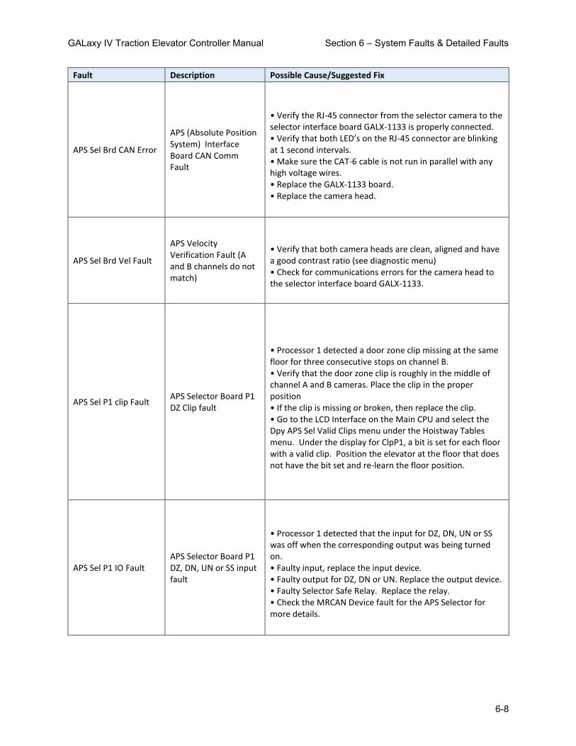
GALaxy IV Traction Elevator Controller Manual Section 6 – System Faults & Detailed Faults
6-8
Fault Description Possible Cause/Suggested Fix
APS Sel Brd CAN Error
APS (Absolute Position System) Interface Board CAN Comm Fault
• Verify the RJ-45 connector from the selector camera to the selector interface board GALX-1133 is properly connected. • Verify that both LED’s on the RJ-45 connector are blinking at 1 second intervals. • Make sure the CAT-6 cable is not run in parallel with any high voltage wires. • Replace the GALX-1133 board. • Replace the camera head.
APS Sel Brd Vel Fault
APS Velocity Verification Fault (A and B channels do not match)
• Verify that both camera heads are clean, aligned and have a good contrast ratio (see diagnostic menu) • Check for communications errors for the camera head to the selector interface board GALX-1133.
APS Sel P1 clip Fault APS Selector Board P1 DZ Clip fault
• Processor 1 detected a door zone clip missing at the same floor for three consecutive stops on channel B. • Verify that the door zone clip is roughly in the middle of channel A and B cameras. Place the clip in the proper position • If the clip is missing or broken, then replace the clip. • Go to the LCD Interface on the Main CPU and select the Dpy APS Sel Valid Clips menu under the Hoistway Tables menu. Under the display for ClpP1, a bit is set for each floor with a valid clip. Position the elevator at the floor that does not have the bit set and re-learn the floor position.
APS Sel P1 IO Fault APS Selector Board P1 DZ, DN, UN or SS input fault
• Processor 1 detected that the input for DZ, DN, UN or SS was off when the corresponding output was being turned on. • Faulty input, replace the input device. • Faulty output for DZ, DN or UN. Replace the output device. • Faulty Selector Safe Relay. Replace the relay. • Check the MRCAN Device fault for the APS Selector for more details.
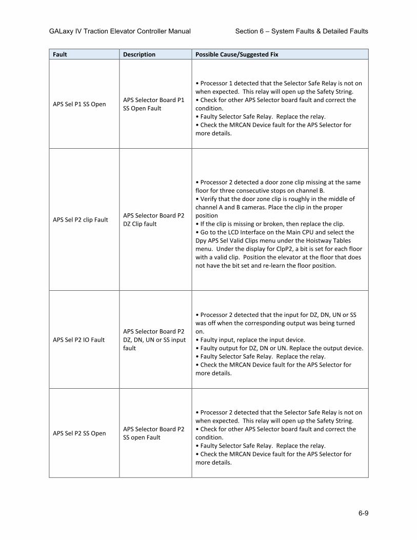
GALaxy IV Traction Elevator Controller Manual Section 6 – System Faults & Detailed Faults
6-9
Fault Description Possible Cause/Suggested Fix
APS Sel P1 SS Open APS Selector Board P1 SS Open Fault
• Processor 1 detected that the Selector Safe Relay is not on when expected. This relay will open up the Safety String. • Check for other APS Selector board fault and correct the condition. • Faulty Selector Safe Relay. Replace the relay. • Check the MRCAN Device fault for the APS Selector for more details.
APS Sel P2 clip Fault APS Selector Board P2 DZ Clip fault
• Processor 2 detected a door zone clip missing at the same floor for three consecutive stops on channel B. • Verify that the door zone clip is roughly in the middle of channel A and B cameras. Place the clip in the proper position • If the clip is missing or broken, then replace the clip. • Go to the LCD Interface on the Main CPU and select the Dpy APS Sel Valid Clips menu under the Hoistway Tables menu. Under the display for ClpP2, a bit is set for each floor with a valid clip. Position the elevator at the floor that does not have the bit set and re-learn the floor position.
APS Sel P2 IO Fault APS Selector Board P2 DZ, DN, UN or SS input fault
• Processor 2 detected that the input for DZ, DN, UN or SS was off when the corresponding output was being turned on. • Faulty input, replace the input device. • Faulty output for DZ, DN or UN. Replace the output device. • Faulty Selector Safe Relay. Replace the relay. • Check the MRCAN Device fault for the APS Selector for more details.
APS Sel P2 SS Open APS Selector Board P2 SS open Fault
• Processor 2 detected that the Selector Safe Relay is not on when expected. This relay will open up the Safety String. • Check for other APS Selector board fault and correct the condition. • Faulty Selector Safe Relay. Replace the relay. • Check the MRCAN Device fault for the APS Selector for more details.

GALaxy IV Traction Elevator Controller Manual Section 6 – System Faults & Detailed Faults
6-10
Fault Description Possible Cause/Suggested Fix
APS Selector CAN Err APS (Absolute Position System) Selector CAN comm error
• Verify the proper connection for the twisted pair wires to the ENC-H and ENC-L terminals on GALX-1100AN CPU Board. • Noise on the CAN Bus, verify that the shield wire is connected according to the job print.
APS Selector Fault APS (Absolute Position System) Selector Fault
• This fault may occur due to either an internal error, communications error, position validation error, velocity validation error on the APS Selector. • Possible solution is to clean the APS tape with damp soft cloth. • Check the MRCAN Device fault for the APS Selector for more details.
ASV Time-out Car 1 Automatic Service Time-out Car 1
• Car was not able to answer group hall call within the automatic service time-out timer. Look for fault condition on car.
ASV Time-out Car 2 Automatic Service Time-out Car 2
• Car was not able to answer group hall call within the automatic service time-out timer. Look for fault condition on car.
ASV Time-out Car 3 Automatic Service Time-out Car 3
• Car was not able to answer group hall call within the automatic service time-out timer. Look for fault condition on car.
ASV Time-out Car 4 Automatic Service Time-out Car 4
• Car was not able to answer group hall call within the automatic service time-out timer. Look for fault condition on car.
ASV Time-out Car 5 Automatic Service Time-out Car 5
• Car was not able to answer group hall call within the automatic service time-out timer. Look for fault condition on car.
ASV Time-out Car 6 Automatic Service Time-out Car 6
• Car was not able to answer group hall call within the automatic service time-out timer. Look for fault condition on car.

GALaxy IV Traction Elevator Controller Manual Section 6 – System Faults & Detailed Faults
6-11
Fault Description Possible Cause/Suggested Fix
ASV Time-out Car 7 Automatic Service Time-out Car 7
• Car was not able to answer group hall call within the automatic service time-out timer. Look for fault condition on car.
ASV Time-out Car 8 Automatic Service Time-out Car 8
• Car was not able to answer group hall call within the automatic service time-out timer. Look for fault condition on car.
At Floor Shutdown At floor shutdown • Car faulted out while at floor. Look at the fault log for a different fault at the same time to determine cause of failure
Aut Swg Fr Door Open
Automatic Swing Front Door Open Fault. The swing door can only close by removing the door open signal and allowing the door to close mechanically. With this fault the door stayed open when the open signal was removed.
• Verify that the ADO output has not failed on. If so then replace the output chip. • Verify that the door is not binding and is preventing from closing.
Aut Swg Rr Door Open
Automatic Swing Rear Door Open Fault. The swing door can only close by removing the door open signal and allowing the door to close mechanically. With this fault the door stayed open when the open signal was removed.
• Verify that the ADOR output has not failed on. If so then replace the output chip. • Verify that the door is not binding and is preventing from closing.
Binary Input Fault
The floor position, read from binary inputs on the selector, does not match the car position.
• Excessive wear on the selector guides. • Preset magnet is missing or misaligned. • Faulty Hall Effect sensor on sensor board. • Faulty output on selector driver board. • Faulty BP1, BP2 or BP4 input

GALaxy IV Traction Elevator Controller Manual Section 6 – System Faults & Detailed Faults
6-12
Fault Description Possible Cause/Suggested Fix
BKS Fault Slowdown
BKS Brake Switch Fault Slowdown. The brake lift switch dropped during the run causing the car to slowdown at the next available floor
• Faulty brake lift switch. • Low brake hold voltage
Bot Door Lock Fault The Bottom Door Lock failed on while the door was open.
Faulty door lock. • Door lock not adjusted properly. • Jumper placed on door lock circuit. • Faulty wiring to DLB input. • Faulty DLB and DLB-1 inputs (For this to occur both DLB and DLB-1 inputs must fail on). • DOL input failed. Replace DOL input chip. • Door operator open limit DOL is not adjusted properly
Bot Final Limit Flt Bottom Final Limit Open
• Car traveled onto the bottom final limit. • Faulty wiring of the final limit circuit.
Brake Drop Fault
Brake failed to drop. The BKS input did not close while stopped.
• Improper adjustment of brake switch. • Brake failed to drop.
Brake Pick Fault
Brake failed to pick. The BKS input did not open during the run.
• Improper adjustment of brake switch. • Brake failed to pick.

GALaxy IV Traction Elevator Controller Manual Section 6 – System Faults & Detailed Faults
6-13
Fault Description Possible Cause/Suggested Fix
Brake Test Stall Flt
Brake Test Stall Fault. The elevator stalled during a brake test. A stall timer is running during the test using the Learn HW Stall time in the Car Timers menu. This is a protection timer that should never time-out. In the event that the car does not move during the test, the 6 second velocity timer should always expire first.
• Make sure the elevator can run properly at high speed. • Make sure the Learn HW Stall timer is set to 30 seconds or higher. The value set during a successful automatic hoistway learn would work fine.
Brake Test UN/DN Flt
Brake Test UN/DN Fault. The elevator hit the UN limit running in the up direction or DN limit running in the down direction during a brake test. The car will abort the brake test immediately if it is approaching or hits a terminal limit.
• Test run in the direction of the terminal floor. • UN or DN input failed or turned off unexpectedly during the test. Try to run the test again while monitoring the status of the UN and DN inputs. • UN or DN input off prior to starting the test. Check the status of the UN and DN inputs prior to the test and make sure that inputs work as expected. • Selector and/or limit not setup or adjusted properly.
Brake Test UT/DT Flt
Brake Test UT/DT Fault. The elevator hit the UT limit running in the up direction or DT limit running in the down direction during a brake test. The car will abort the brake test immediately if it is approaching or hits a terminal limit.
• Test run in the direction of the terminal floor. • UT or DT input failed or turned off unexpectedly during the test. Try to run the test again while monitoring the status of the UT and DT inputs. • UT or DT input off prior to starting the test. Check the status of the UT and DT inputs prior to the test and make sure that inputs work as expected. • Selector and/or limit not setup or adjusted properly.

GALaxy IV Traction Elevator Controller Manual Section 6 – System Faults & Detailed Faults
6-14
Fault Description Possible Cause/Suggested Fix
BRK CAN Com Error Brake Board Can Communication Error.
• Faulty Can communication wire connection. Verify proper twisted pair wires to the CANH and CANL terminals on the brake board. • Noise on the Can bus. Verify that the shield wire is connected according to the job print.
Brk Flt Set EM Brake Emergency brake set from brake fault
• 'Brake Lift Sw' parameter is set to 2. There was a brake fault and this triggered an emergency brake/ gripper fault
Brk Flt Set Gripper
The Rope Gripper was tripped when the brake did not drop. The brake switch adjustable variable Can be set to only show the brake drop fault if the brake does not drop.
• Improper adjustment of brake switch. • Brake failed to drop.
BRK I/O Failed Off
The BRK input or output has failed off. The BRK coil is wired through a NO contact of MC, a NO regulator release contact of the drive (DON) and a BRK triac of the controller.
• Improper wiring of the brake BRK coil. Refer to prints for wire connections. • Faulty BRKi input. Replace BRKi input chip on the GALX-1102 board. • Faulty BRK output. Replace BRK output chip on the GALX-1102 board.
BRK I/O Failed On The BRK input or output has failed on.
• Improper wiring of the brake BRK coil. Refer to prints for wire connections. • Faulty BRKi input. Replace BRKi input chip on the GALX-1102 board. • Faulty BRK output. Replace BRK output chip on the GALX-1102 board.
BRK Low DC Bus Volts DC Bus Voltage is less than 80% of expected
• Incorrect Setting of Line to Line Brake voltage in Adjustable Variables • Incorrect dip-switch setting for Three Phase or Single Phase • Low Line Voltage • Rectifiers Blown or have bad connection

GALaxy IV Traction Elevator Controller Manual Section 6 – System Faults & Detailed Faults
6-15
Fault Description Possible Cause/Suggested Fix
BRK No Currnt w/Volt Reading a resistance value (Vout/Aout) of 1000Ω or greater
• No Brake Connected • Bad Current Sensor • Check if board is low current or high current board
BRK No DC Bus Volts DC Bus Voltage is less than 5VDC
• No AC Voltage Coming into AC1-AC2-AC3 • Rectifiers Blown or have bad Connection
BRK No Output Volts
If no DCBus Faults, Requested Output Voltage is greater than 0, Actual Output voltage is less than 3VDC
• IGBT Not Gating
BRK Over Current Flt
Average Current is higher than Preset Limit (based on board configuration)
• IGBT Shorted • Free Wheeling Diode Shorted • Gating Circuitry Shorted ON
BRK Over Voltage Flt
Output Voltage is at least 20V greater than the Voltage Requested.
• IGBT Shorted • Gating Circuitry shorted ON
BRK Rq Volt > DC Bus
Requested Output Voltage is 5% greater than the DC Bus Voltage
• Incorrect Setting of Pick/Hold/Re-level Voltage in Adjustable Variables • Low Line Voltage
Brk Test UTS/DTS Flt
Brake Test UTS/DTS Fault. The elevator hit the UTS limit running in the up direction or DTS limit running in the down direction during a brake test. The car will abort the brake test immediately if it is approaching or hits a terminal limit.
• Test run in the direction of the terminal floor. • UTS or DTS input failed or turned off unexpectedly during the test. Try to run the test again while monitoring the status of the UTS and DTS inputs. • UTS or DTS input off prior to starting the test. Check the status of the UTS and DTS inputs prior to the test and make sure that inputs work as expected. • Selector and/or limit not setup or adjusted properly.

GALaxy IV Traction Elevator Controller Manual Section 6 – System Faults & Detailed Faults
6-16
Fault Description Possible Cause/Suggested Fix
Brk Test Vel Time-out
Brake Test Velocity Time-out. The car has 6 seconds to reach within 10 fpm of the top speed parameter. (See the Top Speed parameter in the Car Motion menu). The test is aborted if the desired speed is not reached within the 6 second time period.
• The car did not reach top speed during the test. Make sure the car can reach top speed during a normal run. • Make sure that the encoder velocity feedback is displaying the correct velocity. • If it is necessary to run the test before the car can run top speed, reduce the top speed parameter in the Car Motion menu to a speed value that the car can reach within 6 seconds. • For a high speed car, the speed profile parameters may need to be adjusted so that the car can reach top speed quickly.
Buffer Switch Fault Buffer Switch Open
• Verify that the buffer switch is set and the switch is closed. • Faulty wiring on the buffer switch circuit. • Car hit the buffer
Can Bus Off Error
Can Bus Off Error. The Can bus has been inactive for too long a period of time.
• Faulty CAN bus wiring. Check the Can bus terminal connections on all boards.
CAN spb bad command
Unintended Motion Command to Safety Processor unintentionally set
• This fault should never occur. Contact GAL.
Car 1 Comm Loss The group car is not communicating with Car 1.
• Faulty wiring from R/T+ and R/T- from car to car. • Faulty U6 driver chip on 1100 board. • Noise on shield wire. Connect shield only on one end. • Noise on the communication wires. Run wires in separate conduit.
Car 2 Comm Loss The group car is not communicating with Car 2.
• Faulty wiring from R/T+ and R/T- from car to car. • Faulty U6 driver chip on 1100 board. • Noise on shield wire. Connect shield only on one end. • Noise on the communication wires. Run wires in separate conduit.

GALaxy IV Traction Elevator Controller Manual Section 6 – System Faults & Detailed Faults
6-17
Fault Description Possible Cause/Suggested Fix
Car 3 Comm Loss The group car is not communicating with Car 3.
• Faulty wiring from R/T+ and R/T- from car to car. • Faulty U6 driver chip on 1100 board. • Noise on shield wire. Connect shield only on one end. • Noise on the communication wires. Run wires in separate conduit.
Car 4 Comm Loss The group car is not communicating with Car 4.
• Faulty wiring from R/T+ and R/T- from car to car. • Faulty U6 driver chip on 1100 board. • Noise on shield wire. Connect shield only on one end. • Noise on the communication wires. Run wires in separate conduit.
Car 5 Comm Loss The group car is not communicating with Car 5.
• Faulty wiring from R/T+ and R/T- from car to car. • Faulty U6 driver chip on 1100 board. • Noise on shield wire. Connect shield only on one end. • Noise on the communication wires. Run wires in separate conduit.
Car 6 Comm Loss The group car is not communicating with Car 6
• Faulty wiring from R/T+ and R/T- from car to car. • Faulty U6 driver chip on 1100 board. • Noise on shield wire. Connect shield only on one end. • Noise on the communication wires. Run wires in separate conduit.
Car 7 Comm Loss The group car is not communicating with Car 7
• Faulty wiring from R/T+ and R/T- from car to car. • Faulty U6 driver chip on 1100 board. • Noise on shield wire. Connect shield only on one end. • Noise on the communication wires. Run wires in separate conduit.
Car 8 Comm Loss The group car is not communicating with Car 8
• Faulty wiring from R/T+ and R/T- from car to car. • Faulty U6 driver chip on 1100 board. • Noise on shield wire. Connect shield only on one end. • Noise on the communication wires. Run wires in separate conduit.
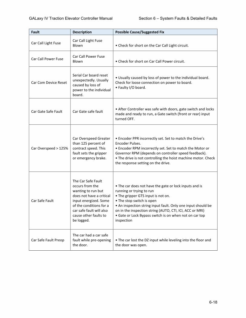
GALaxy IV Traction Elevator Controller Manual Section 6 – System Faults & Detailed Faults
6-18
Fault Description Possible Cause/Suggested Fix
Car Call Light Fuse Car Call Light Fuse Blown
• Check for short on the Car Call Light circuit.
Car Call Power Fuse Car Call Power Fuse Blown
• Check for short on Car Call Power circuit.
Car Com Device Reset
Serial Car board reset unexpectedly. Usually caused by loss of power to the individual board.
• Usually caused by loss of power to the individual board. Check for loose connection on power to board. • Faulty I/O board.
Car Gate Safe Fault Car Gate safe fault
• After Controller was safe with doors, gate switch and locks made and ready to run, a Gate switch (front or rear) input turned OFF.
Car Overspeed > 125%
Car Overspeed Greater than 125 percent of contract speed. This fault sets the gripper or emergency brake.
• Encoder PPR incorrectly set. Set to match the Drive’s Encoder Pulses. • Encoder RPM incorrectly set. Set to match the Motor or Governor RPM (depends on controller speed feedback). • The drive is not controlling the hoist machine motor. Check the response setting on the drive.
Car Safe Fault
The Car Safe Fault occurs from the wanting to run but does not have a critical input energized. Some of the conditions for a car safe fault will also cause other faults to be logged.
• The car does not have the gate or lock inputs and is running or trying to run • The gripper GTS input is not on. • The stop switch is open • An inspection string input fault. Only one input should be on in the inspection string (AUTO, CTI, ICI, ACC or MRI) • Gate or Lock Bypass switch is on when not on car top inspection
Car Safe Fault Preop The car had a car safe fault while pre-opening the door.
• The car lost the DZ input while leveling into the floor and the door was open.

GALaxy IV Traction Elevator Controller Manual Section 6 – System Faults & Detailed Faults
6-19
Fault Description Possible Cause/Suggested Fix
Car Safe Fault Start
The car had an onward call, had the door close limit but the car gate or door locks did not make after a 3 second time-out.
• The locks are not making properly when the door closes. • The door is not closing properly.
Car Safety Sw. Fault Car Safety Switch Fault • Verify that the car safety is not tripped. • Faulty wiring in the car safety circuit
Car Top Stop Switch Car top stop switch • Safety String Fault. Refer to Safety String Page on Diagrams. Check/replace input Chip.
CCB FET Open Blue Car Call Board FET open blue
• Faulty LED signal from RGB Board. Look at detailed car faults log to determine device. 'dev' gives you address for global CAN device, 'dv2' gives you local CAN device and 'pf1' the number for the IO location within the local board.
CCB FET Open Green Car Call Board FET open green
• Faulty LED signal from RGB Board. Look at detailed car faults log to determine device. 'dev' gives you address for global CAN device, 'dv2' gives you local CAN device and 'pf1' the number for the IO location within the local board.
CCB FET Open Red Car Call Board FET open red
• Faulty LED signal from RGB Board. Look at detailed car faults log to determine device. 'dev' gives you address for global CAN device, 'dv2' gives you local CAN device and 'pf1' the number for the IO location within the local board.
CCB FET Short Blue Car Call Board FET short blue
• Faulty LED signal from RGB Board. Look at detailed car faults log to determine device. 'dev' gives you address for global CAN device, 'dv2' gives you local CAN device and 'pf1' the number for the IO location within the local board.

GALaxy IV Traction Elevator Controller Manual Section 6 – System Faults & Detailed Faults
6-20
Fault Description Possible Cause/Suggested Fix
CCB FET Short Green Car Call Board FET short green
• Faulty LED signal from RGB Board. Look at detailed car faults log to determine device. 'dev' gives you address for global CAN device, 'dv2' gives you local CAN device and 'pf1' the number for the IO location within the local board.
CCB FET Short Red Car Call Board FET short red
• Faulty LED signal from RGB Board. Look at detailed car faults log to determine device. 'dev' gives you address for global CAN device, 'dv2' gives you local CAN device and 'pf1' the number for the IO location within the local board.
CCB LED Open Blue Car Call Board LED open blue
• Faulty LED signal from RGB Board. Look at detailed car faults log to determine device. 'dev' gives you address for global CAN device, 'dv2' gives you local CAN device and 'pf1' the number for the IO location within the local board.
CCB LED Open Green Car Call Board LED open green
• Faulty LED signal from RGB Board. Look at detailed car faults log to determine device. 'dev' gives you address for global CAN device, 'dv2' gives you local CAN device and 'pf1' the number for the IO location within the local board.
CCB LED Open Red Car Call Board LED open red
• Faulty LED signal from RGB Board. Look at detailed car faults log to determine device. 'dev' gives you address for global CAN device, 'dv2' gives you local CAN device and 'pf1' the number for the IO location within the local board.
CCB LED Short Blue Car Call Board LED short blue
• Faulty LED signal from RGB Board. Look at detailed car faults log to determine device. 'dev' gives you address for global CAN device, 'dv2' gives you local CAN device and 'pf1' the number for the IO location within the local board.

GALaxy IV Traction Elevator Controller Manual Section 6 – System Faults & Detailed Faults
6-21
Fault Description Possible Cause/Suggested Fix
CCB LED Short Green Car Call Board LED short green
• Faulty LED signal from RGB Board. Look at detailed car faults log to determine device. 'dev' gives you address for global CAN device, 'dv2' gives you local CAN device and 'pf1' the number for the IO location within the local board.
CCB LED Short Red Car Call Board LED short red
• Faulty LED signal from RGB Board. Look at detailed car faults log to determine device. 'dev' gives you address for global CAN device, 'dv2' gives you local CAN device and 'pf1' the number for the IO location within the local board.
CCB No Comm Aux Bd 1
Car Call Board local aux board 1 comm loss
• Comm loss to RGB Auxiliary Car Call Board. Check wiring and bus termination jumpers on boards. If problem persists, check Car Comm Status under diagnostics.
CCB No Comm Aux Bd 2
Car Call Board local aux board 2 comm loss
• Comm loss to RGB Auxiliary Car Call Board. Check wiring and bus termination jumpers on boards. If problem persists, check Car Comm Status under diagnostics.
CCB No Comm Board 1
Car Call Board local board 1 comm loss
• Comm loss to RGB Car Call Board. Check wiring and bus termination jumpers on boards. If problem persists, check Car Comm Status under diagnostics.
CCB No Comm Board 2
Car Call Board local board 2 comm loss
• Comm loss to RGB Car Call Board. Check wiring and bus termination jumpers on boards. If problem persists, check Car Comm Status under diagnostics.
CCB No LED Board Car Call LED board missing
• Faulty LED signal from RGB Board. Look at detailed car faults log to determine device. 'dev' gives you address for global CAN device, 'dv2' gives you local CAN device and 'pf1' the number for the IO location within the local board.

GALaxy IV Traction Elevator Controller Manual Section 6 – System Faults & Detailed Faults
6-22
Fault Description Possible Cause/Suggested Fix
CCB Stuck Button Car Call Board stuck button
• Faulty LED signal from RGB Board. Look at detailed car faults log to determine device. 'dev' gives you address for global CAN device, 'dv2' gives you local CAN device and 'pf1' the number for the IO location within the local board.
Comm Fault (From SEL)
Selector not communicating to the main CPU.
• Faulty Can communication wire connection. Verify proper twisted pair wires to the CANH and CANL terminals on the board. • Noise on the Can bus. Verify that the shield wire is connected according to the job print. See: SEL Dev CAN Fault
Comm Fault (From SPB)
Safety Processor not communicating to the main CPU.
• Faulty Can communication wire connection. Verify proper twisted pair wires to the CANH and CANL terminals on the board. • Noise on the Can bus. Verify that the shield wire is connected according to the job print. See: SPB Dev CAN Fault
Comp. Switch Fault Compensating Rope Switch Open
• Verify that the compensating rope switch is set and the switch is closed. • Improper cabling of the compensating ropes on the sheave.
COP CAN Com Error COP Board Can Communication Error.
• Faulty Can communication wire connection. Verify proper twisted pair wires to the CANH and CANL terminals on the COP board. • Noise on the Can bus. Verify that the shield wire is connected according to the job print.
CTCAN Device Fault Device on the Car Top CAN Port has a Fault
• Look at the details of the fault. The device name and the error code that caused the fault are listed. • Look up the fault code for the device for debugging information.

GALaxy IV Traction Elevator Controller Manual Section 6 – System Faults & Detailed Faults
6-23
Fault Description Possible Cause/Suggested Fix
CTCAN Device Reset Device on the Car Top CAN Port has reset
• Look at the details of the fault. The device name and the error code that caused the fault are listed. • The device requested an initialization packet from the main CPU. Typically this occurs during power up or from a power cycle of the individual device. • Ignore the error if the controller power has been cycled. Otherwise, check the device communications and power connections.
CWT Sw Error at DT
Car 'above cwt' flag was set for above the counterweight when the car hit the down terminal slowdown limit.
• The counterweight switch was not hit during the run or the car was lost when powered up. • Faulty wiring of the counterweight switch. • Improper adjustment of the counterweight switch.
CWT Sw Error at UT
Car 'above cwt' flag was set for below the counterweight when the car hit the up terminal slowdown limit.
• The counterweight switch was not hit during the run or the car was lost when powered up. • Faulty wiring of the counterweight switch. • Improper adjustment of the counterweight switch.
DBR Temperature Flt
Dynamic Braking Resistor Temperature Fault. The temperature for the dynamic braking resistors is read in through a temperature sensor mounted above the resistors. When the temperature sensor opens a contact, the CPU detects a temperature fault, an error is recorded, the car is shut down at the next floor and the DBC relay is de energized to open the DB Resistor circuit.
• Faulty Temperature Sensor. If the DB Resistors are not hot, check the temperature sensor input board connected to the CPU board. The input LED should be on when the temperature is okay. If the LED is not on, jump the two terminals on the temperature input board and the LED should go on. If the LED goes on then the Temperature Sensor is bad. Replace the Temperature Sensor. • Faulty Temperature Sensor Input Board. Test the sensor input as above. If the LED does not turn on when the input terminals are jumped together, replace the Temperature Sensor Input Board.

GALaxy IV Traction Elevator Controller Manual Section 6 – System Faults & Detailed Faults
6-24
Fault Description Possible Cause/Suggested Fix
Delta off Fault DEL input did not come on at start or went off during a run.
• The delta contact did not make on a Y-Delta starter. • The MC contact did not make on an across-the-line starter • The 'at speed' contact did not make on an electronic soft-starter. • Faulty DEL input. Replace the DEL input chip.
Delta On Fault
DEL input failed on when is should have been off. This would occur at the start of a run when the I/O’s are checked. The input failed on or the contact for the input failed closed.
• Faulty DEL input (failed on). Check the input and output status on the LCD interface. • Faulty contact for DEL input failed on. Replace the DEL input chip.
DF I/O Failed Off The DF input or output has failed off
Hydro • Fault on Safety Processor Board. The Safety Processor Board can disable the run control to the SDF output chip. Check if the PIC or PAL inhibit LED turns on when the car attempts to run. Check the elevator service, faults, and inputs/outputs on the Safety Processor Board LCD display. • Faulty wiring to the SC common on the MAIN I/O board. • Faulty wiring to the SDF terminal on the MAIN I/O board. • Faulty wiring to the Down Fast valve. • Faulty SDFi input (replace input chip). • Faulty SDF output (replace output chip).
DF I/O Failed On The DF input or output has failed on.
Hydro • Faulty SDFi input (replace input chip). • Faulty SDF output (replace output chip).
DL Failed On Fault
DL Failed On Fault. The DL leveling sensor did not turn off during a run.
• DL hall effect sensor bad on selector sensor board. Replace sensor board. • DL input on selector driver board is bad. Replace selector driver board.

GALaxy IV Traction Elevator Controller Manual Section 6 – System Faults & Detailed Faults
6-25
Fault Description Possible Cause/Suggested Fix
DL/GS Fault Safety Processor Door Lock/Gate Switch Fault
• Car is moving outside the door zone with the door open. The car will immediately shut down. See: SPB DL/GS Fault
DL20 Phone Test Failed
Phone Test from DL20 phone monitoring device indicated a failure
• Refer to the manufacturers troubleshooting guide for the DL20.
DLB & DLB-1 Opposite
Input failure on one of the Door Lock Bottom (DLB) inputs.
• Faulty DLB or DLB-1 input (replace input chip).
DLB open w/R Acc DLT
Door Lock Bottom open with Rear Access Door Lock Top is open at the top floor.
• Incorrect door lock wiring. Wire according to the job schematic. • If access is enabled, verify that the correct lock is wired for the front or rear door that will open on access.
DLB open with DLM
Door Lock Bottom is open while the Door Lock Middle is open at a middle floor.
• Incorrect door lock wiring. Wire according to the job schematic. • If access is enabled, verify that the correct lock is wired for the front or rear door that will open on access.
DLB open with DLT
Door Lock Bottom is open while the Door Lock Top is open at a top floor.
• Incorrect door lock wiring. Wire according to the job schematic. • If access is enabled, verify that the correct lock is wired for the front or rear door that will open on access.
DLB open with RLM
Door Lock Bottom is open while the Rear Door Lock Middle is open at a middle floor.
• Incorrect door lock wiring. Wire according to the job schematic. • If access is enabled, verify that the correct lock is wired for the front or rear door that will open on access.
DLM & DLM-1 Opposite
Input failure on one of the Door Lock Middle (DLM) inputs.
• Faulty DLM or DLM-1 input (replace input chip).

GALaxy IV Traction Elevator Controller Manual Section 6 – System Faults & Detailed Faults
6-26
Fault Description Possible Cause/Suggested Fix
DLM open with DLB
Door Lock Middle is open while the Door Lock Bottom is open at a bottom floor.
• Incorrect door lock wiring. Wire according to the job schematic. • If access is enabled, verify that the correct lock is wired for the front or rear door that will open on access.
DLM open with DLT
Door Lock Middle is open while the Door Lock Top is open at a top floor.
• Incorrect door lock wiring. Wire according to the job schematic. • If access is enabled, verify that the correct lock is wired for the front or rear door that will open on access.
DLT & DLT-1 Opposite
Input failure on one of the Door Lock Top (DLT) inputs.
• Faulty DLT or DLT-1 input (replace input chip).
DLT open w/R Acc DLB
Door Lock Top open with Rear Access Door Lock Bottom is open at the bottom floor.
• Incorrect door lock wiring. Wire according to the job schematic. • If access is enabled, verify that the correct lock is wired for the front or rear door that will open on access.
DLT open with DLB
Door Lock Top is open while the Door Lock Bottom is open at a bottom floor.
• Incorrect door lock wiring. Wire according to the job schematic. • If access is enabled, verify that the correct lock is wired for the front or rear door that will open on access.
DLT open with DLM
Door Lock Top is open while the Door Lock Middle is open at a middle floor.
• Incorrect door lock wiring. Wire according to the job schematic. • If access is enabled, verify that the correct lock is wired for the front or rear door that will open on access.
DLT open with RLM
Door Lock Top is open while the Rear Door Lock Middle is open at a middle floor.
• Incorrect door lock wiring. Wire according to the job schematic. • If access is enabled, verify that the correct lock is wired for the front or rear door that will open on access.

GALaxy IV Traction Elevator Controller Manual Section 6 – System Faults & Detailed Faults
6-27
Fault Description Possible Cause/Suggested Fix
Dn Directional Fault Car unexpectedly hit the Down Normal Limit while running down.
• Faulty wiring for the DN limit. • Tape Selector: Incorrect placement of DT magnet (too close to center of tape). • Tapeless Selector: Incorrect placement of DT magnet not aligned properly with magnetic sensor on selector (cross talk from DT magnet to DN sensor).
Dn Normal SW Setup
Down Normal must be on before reaching bottom floor dead level
• The down normal needs to be moved down so when the car is Dead level at the bottom landing DN is ON. Allow at least 2 inches run before DN turns OFF
DN Pulse Fault
Selector pulsed the DN latch multiple times but the DN state was not latched
• Memory of the DN sensor is stored on a state saver latch device. Replace the Selector Board. See: SEL DN Pulse Fault
DNR I/O Failed Off The DNR input or output has failed off.
• Fault on Safety Processor. The Safety Processor is located on the MAIN I/O board. This device can disable the run control to the DNR output chip. Check if the SAF-PROC or SAF-PAL FAULT LEDs turn on when the car attempts to run. Check the elevator service, faults, and inputs/outputs on the Safety Processor status of the LCD Display Interface. • Faulty DNR output or DNRi input. Replace the DNR output and DNRi input chip. • No 24VDC from the drive. Refer to Schematics. • Incorrect jumper placement on MAIN I/O board. Verify that jumpers on the bottom center of the board are positioned correctly for SOURCE or SINK. The jumpers depend on the drive type and is shown on the drive portion of the job schematic. If necessary move the jumpers to the correct position. • RUN, MC or BRK auxiliary contact not making properly. Verify the operation and contact integrity.

GALaxy IV Traction Elevator Controller Manual Section 6 – System Faults & Detailed Faults
6-28
Fault Description Possible Cause/Suggested Fix
DNR I/O Failed On The DNR input or output has failed on.
• Faulty DNR output. Replace the DNR output chip. • Faulty DNRi input. Replace DNRi input chip. • Incorrect jumper placement on MAIN I/O board. Verify that jumpers on the bottom center of the board are positioned correctly for SOURCE or SINK. The jumpers depend on the drive type and is shown on the drive portion of the job schematic. If necessary move the jumpers to the correct position.
DON I/O Failed Off
The DON input or the drive run relay contact has failed off. The run relay on the drive turns on the DON input (Drive ON) indicating that the regulator is released and the drive is controlling the motor.
• Loss of voltage on terminal SFC. • MC contact in series with the drive run relay opened. See MCX Off Fault for additional information. • The drive faulted on start and dropped the run relay. Check the drive fault log. • Faulty DRO relay controlled by the drive. • Faulty DON input on the controller. Replace the DON input chip. • The run relay in the drive is not programmed properly. Check the default drive setup for the run relay output.
DON I/O Failed On
The DON input or the drive output has failed on. When the drive is turned off, the run relay on the drive will drop out turning off DON.
• Improper wiring of the Drive On contact controlled by the drive.. Refer to prints for wire connections. • Faulty wiring to the DON input. • Faulty DON input on the controller. Replace the DON input chip. • Faulty DRO relay failed on. • The control of the DRO relay by the drive is not programmed properly. Check the default drive setup for the Drive On output.
Door Close Fault
The door did not reach the Door Close Limit within the door close protection time.
• Door Close Limit (DCL) not adjusted properly. • Faulty Door Close Limit (DCL). Replace DCL input chip. • Trash in door track preventing door from closing.
Door Lock Safe Fault Door lock safe fault • After Controller was safe with doors, gate switch and locks made and ready to run, a door lock input turned OFF.

GALaxy IV Traction Elevator Controller Manual Section 6 – System Faults & Detailed Faults
6-29
Fault Description Possible Cause/Suggested Fix
Door Low Voltage Flt Door Line Voltage Low
• Voltage Sensor Board Related. Voltage being monitored for Door Operator dropped below the setting for parameter 'Low Door Volt '
Door Motor Overload Door Motor Overload • Door Motor Overload signal tripped. Check Input chip for DMO signal
Door Open Fault
The door did not reach the Door Open Limit within the door open protection time.
• Door Open Limit (DOL) not adjusted properly. • Faulty Door Open Limit (DOL). Replace DOL input chip.
Door Zone Aux On Flt The auxiliary door zone input failed on.
• One or both of the DZA sensors on the selector sensor board failed. Replace selector sensor board. • Faulty selector board. Replace the selector board.
Door Zone Off Fault
Door Zone Fault occurs from the following conditions: • The car is not on UL or DL when expected. • The car does not have DZ when expected. • The DZ relay does not drop out while in motion.
The car does not have DZ when it is expected to be level at the floor. DZ output on selector board failed on or did not turn on. (Replace DZ output on selector driver board). One or both of the DZ sensors on the selector sensor board failed. Replace selector sensor board. • DZ input on the GALX-1102 board failed on or off. Replace DZ input on the GALX-1102 board.
Door Zone On Fault The door zone input failed on.
• DZ output on selector board did not turn off. (Replace DZ output on selector driver board). • One or both of the DZ sensors on the selector sensor board failed. Replace selector sensor board. • DZ input on the GALX-1102 board failed. Replace DZ input on the GALX-1102 board.
DoorZone Aux Off Flt The auxiliary door zone input failed off.
• One or both of the DZA sensors on the selector sensor board failed. Replace selector sensor board. • Faulty Selector Driver Board. Replace the Selector Board

GALaxy IV Traction Elevator Controller Manual Section 6 – System Faults & Detailed Faults
6-30
Fault Description Possible Cause/Suggested Fix
DPM Input Fault
The DPM input fault occurs when door opens and the DPM input did not go off.
• DPM switch not setup properly on the door operator. • Faulty DPM input. Replace DPM input chip.
DPM Off/GS or DL On
DPM Off with Gate Switch or Door Lock On. The Door Protection Module input must go on before gate switch or door lock inputs go on.
• The DPM switch on the door operator is not setup properly. DPM should turn on before the Gate Switch is made. • There is no DPM input on the door operator. Jump the DPM input to the GS-1 terminal. • Fault DPM input. Replace the DPM input chip.
Drive Com Rcv Error
Controller has a communications error with drive. The controller has not received a valid message from the drive for more than one second.
• Faulty communications cable connection. Check the drive twisted pairs connected from the drive to the 1100 CPU board. • Noise on the communication cable. Verify that the shield on the communications cable to the drive is connected to earth ground on one end. • Open the DB9 connector to the drive and verify that the wires are soldered properly. • Faulty communication chip. Replace the 1100 CPU board.
Drive has Com Error
Drive has a communications error. The controller has received a message from the drive that it has communication receive errors.
• Faulty communications cable connection. Check the drive twisted pairs connected from the drive to the 1100 CPU board. • Noise on the communication cable. Verify that the shield on the communications cable to the drive is connected to earth ground on one end. • Open the DB9 connector to the drive and verify that the wires are soldered properly. • Faulty communication chip. Replace the 1100 CPU board.
Drive Ready Fault The drive has a fault
• The drive has or had a fault. Check the drive fault log. • Faulty RDY input. (Replace the RDY input). • Faulty Drive SFD relay. (Replace the SFD Relay). • Faulty Drive RDY relay. (Replace the RDY Relay).

GALaxy IV Traction Elevator Controller Manual Section 6 – System Faults & Detailed Faults
6-31
Fault Description Possible Cause/Suggested Fix
DT count Fault
The verification position count for the DT input switch was off by more than 10 inches when the switch was activated.
• The car was lost due to a preset error. Check the guides on the selector. Check the fault log for binary preset errors. • The controller has a faulty encoder signal for the pulse count. Check that the car can make long runs without overshooting the floor or stopping short of the floor. • The power common to the limit switches was lost. Check fuse F1 on the selector board. • Incorrect counting of pulse counts. For Tapeless, check encoder connection to motor and encoder wiring. For Tape, check pulse sensors for proper quadrature at selector. • Hoistway not learned properly. Perform a hoistway learn procedure. • DT magnet not adjusted properly. Check at slow speed if sensor input is breaking, making and then breaking again. Magnet needs to be closer to the sensor on the selector.
DT Failed On Fault
DT input Failed On Fault. The car was at the bottom floor and the DTS input was low (DTS switch made) but the DT input was high (DT not made).
• The DTS limit is not installed. The DTS limit is used on all controllers as a verification that the car is at the bottom most landing. Add the DTS limit. • The DT did not break at the bottom terminal landing. Adjust or replace the DT switch. • Faulty DT input. Replace selector board. • Faulty DT sensor on selector sensor board. Replace the sensor board for tape selector or replace the individual DT sensor on tapeless selector.
DT Limit Vel Fault
NTS Processor detected a car speed at the DT terminal limit that was greater that the clamp (parameter) speed
• Verify that the limit activates at the correct location in the hoistway. • Verify the speed that the car hits the limit and adjust the limit velocity if necessary. • If the acceleration or deceleration rates were changed after the limit velocities were learned, the learn process may need to be repeated or the limit may need to be moved. See: NTS DT Limit Vel Flt

GALaxy IV Traction Elevator Controller Manual Section 6 – System Faults & Detailed Faults
6-32
Fault Description Possible Cause/Suggested Fix
DT Pulse Fault
Selector pulsed the DT latch multiple times but the DT state was not latched
• Memory of the DT sensor is stored on a state saver latch device. Replace the Selector Board. See: SEL DT Pulse Fault
DT Speed Fault
Car hit the DT Limit at a speed greater than the speed limit setting parameter.
• Error previously set from the Safety Processor that is no long used. (See DT Limit Vel Fault).
DT1 count Fault
The verification position count for the DT1 input switch was off by more than 10 inches when the switch was activated.
• The car was lost due to a preset error. Check the guides on the selector. Check the fault log for binary preset errors. • The controller has a faulty encoder signal for the pulse count. Check that the car can make long runs without overshooting the floor or stopping short of the floor. • The power common to the limit switches was lost. Check fuse F1 on the selector board. • Incorrect counting of pulse counts. For Tapeless, check encoder connection to motor and encoder wiring. For Tape, check pulse sensors for proper quadrature at selector. • Hoistway not learned properly. Perform a hoistway learn procedure. • DT1 magnet not adjusted properly. Check at slow speed if sensor input is breaking, making and then breaking again. Magnet needs to be closer to the sensor on the selector.
DT1 Limit Vel Fault
NTS Processor detected a car speed at the DT1 terminal limit that was greater that the clamp (parameter) speed
• Verify that the limit activates at the correct location in the hoistway. • Verify the speed that the car hits the limit and adjust the limit velocity if necessary. • If the acceleration or deceleration rates were changed after the limit velocities were learned, the learn process may need to be repeated or the limit may need to be moved. See: NTS DT1 Limit Vel Flt

GALaxy IV Traction Elevator Controller Manual Section 6 – System Faults & Detailed Faults
6-33
Fault Description Possible Cause/Suggested Fix
DT2 count Fault
The verification position count for the DT2 input switch was off by more than 14 inches when the switch was activated.
• The car was lost due to a preset error. Check the guides on the selector. Check the fault log for binary preset errors. • The controller has a faulty encoder signal for the pulse count. Check that the car can make long runs without overshooting the floor or stopping short of the floor. • The power common to the limit switches was lost. Check fuse F1 on the selector board. • Incorrect counting of pulse counts. For Tapeless, check encoder connection to motor and encoder wiring. For Tape, check pulse sensors for proper quadrature at selector. • Hoistway not learned properly. Perform a hoistway learn procedure. • DT2 magnet not adjusted properly. Check at slow speed if sensor input is breaking, making and then breaking again. Magnet needs to be closer to the sensor on the selector.
DT2 Limit Vel Fault
NTS Processor detected a car speed at the DT2 terminal limit that was greater that the clamp (parameter) speed
• Verify that the limit activates at the correct location in the hoistway. • Verify the speed that the car hits the limit and adjust the limit velocity if necessary. • If the acceleration or deceleration rates were change after the limit velocities were learned, the learn process may need to be repeated or the limit may need to be moved. See: NTS DT2 Limit Vel Flt

GALaxy IV Traction Elevator Controller Manual Section 6 – System Faults & Detailed Faults
6-34
Fault Description Possible Cause/Suggested Fix
DT3 count Fault
The verification position count for the DT3 input switch was off by more than 18 inches when the switch was activated.
• The car was lost due to a preset error. Check the guides on the selector. Check the fault log for binary preset errors. • The controller has a faulty encoder signal for the pulse count. Check that the car can make long runs without overshooting the floor or stopping short of the floor. • The power common to the limit switches was lost. Check fuse F1 on the selector board. • Incorrect counting of pulse counts. For Tapeless, check encoder connection to motor and encoder wiring. For Tape, check pulse sensors for proper quadrature at selector. • Hoistway not learned properly. Perform a hoistway learn procedure. • DT3 magnet not adjusted properly. Check at slow speed if sensor input is breaking, making and then breaking again. Magnet needs to be closer to the sensor on the selector.
DT3 Limit Vel Fault
NTS Processor detected a car speed at the DT3 terminal limit that was greater that the clamp (parameter) speed
• Verify that the limit activates at the correct location in the hoistway. • Verify the speed that the car hits the limit and adjust the limit velocity if necessary. • If the acceleration or deceleration rates were changed after the limit velocities were learned, the learn process may need to be repeated or the limit may need to be moved. See: NTS DT3 Limit Vel Flt

GALaxy IV Traction Elevator Controller Manual Section 6 – System Faults & Detailed Faults
6-35
Fault Description Possible Cause/Suggested Fix
DT4 count Fault
The verification position count for the DT4 input switch was off by more than 24 inches when the switch was activated.
• The car was lost due to a preset error. Check the guides on the selector. Check the fault log for binary preset errors. • The controller has a faulty encoder signal for the pulse count. Check that the car can make long runs without overshooting the floor or stopping short of the floor. • The power common to the limit switches was lost. Check fuse F1 on the selector board. • Incorrect counting of pulse counts. For Tapeless, check encoder connection to motor and encoder wiring. For Tape, check pulse sensors for proper quadrature at selector. • Hoistway not learned properly. Perform a hoistway learn procedure. • DT4 magnet not adjusted properly. Check at slow speed if sensor input is breaking, making and then breaking again. Magnet needs to be closer to the sensor on the selector.
DT4 Limit Vel Fault
NTS Processor detected a car speed at the DT terminal limit that was greater that the clamp (parameter) speed
• Verify that the limit activates at the correct location in the hoistway. • Verify the speed that the car hits the limit and adjust the limit velocity if necessary. • If the acceleration or deceleration rates were changed after the limit velocities were learned, the learn process may need to be repeated or the limit may need to be moved. See: NTS DT4 Limit Vel Flt

GALaxy IV Traction Elevator Controller Manual Section 6 – System Faults & Detailed Faults
6-36
Fault Description Possible Cause/Suggested Fix
DT5 count Fault
The verification position count for the DT5 input switch was off by more than 32 inches when the switch was activated.
• The car was lost due to a preset error. Check the guides on the selector. Check the fault log for binary preset errors. • The controller has a faulty encoder signal for the pulse count. Check that the car can make long runs without overshooting the floor or stopping short of the floor. • The power common to the limit switches was lost. Check fuse F1 on the selector board. • Incorrect counting of pulse counts. For Tapeless, check encoder connection to motor and encoder wiring. For Tape, check pulse sensors for proper quadrature at selector. • Hoistway not learned properly. Perform a hoistway learn procedure. • DT5 magnet not adjusted properly. Check at slow speed if sensor input is breaking, making and then breaking again. Magnet needs to be closer to the sensor on the selector.
DT5 Limit Vel Fault
NTS Processor detected a car speed at the DT5 terminal limit that was greater that the clamp (parameter) speed
• Verify that the limit activates at the correct location in the hoistway. • Verify the speed that the car hits the limit and adjust the limit velocity if necessary. • If the acceleration or deceleration rates were changed after the limit velocities were learned, the learn process may need to be repeated or the limit may need to be moved. See: NTS DT5 Limit Vel Flt

GALaxy IV Traction Elevator Controller Manual Section 6 – System Faults & Detailed Faults
6-37
Fault Description Possible Cause/Suggested Fix
DT6 count Fault
The verification position count for the DT6 input switch was off by more than 42 inches when the switch was activated.
• The car was lost due to a preset error. Check the guides on the selector. Check the fault log for binary preset errors. • The controller has a faulty encoder signal for the pulse count. Check that the car can make long runs without overshooting the floor or stopping short of the floor. • The power common to the limit switches was lost. Check fuse F1 on the selector board. • Incorrect counting of pulse counts. For Tapeless, check encoder connection to motor and encoder wiring. For Tape, check pulse sensors for proper quadrature at selector. • Hoistway not learned properly. Perform a hoistway learn procedure. • DT6 magnet not adjusted properly. Check at slow speed if sensor input is breaking, making and then breaking again. Magnet needs to be closer to the sensor on the selector.
DT6 Limit Vel Fault
NTS Processor detected a car speed at the DT6 terminal limit that was greater that the clamp (parameter) speed
• Verify that the limit activates at the correct location in the hoistway. • Verify the speed that the car hits the limit and adjust the limit velocity if necessary. • If the acceleration or deceleration rates were changed after the limit velocities were learned, the learn process may need to be repeated or the limit may need to be moved. See: NTS DT6 Limit Vel Flt

GALaxy IV Traction Elevator Controller Manual Section 6 – System Faults & Detailed Faults
6-38
Fault Description Possible Cause/Suggested Fix
DTS count Fault
Down Terminal Slowdown Limit Count Fault. The verification position count for the DTS input switch was off by more than 10 inches when the switch was activated.
• The car was lost due to a preset error. Check the guides on the selector. Check the fault log for binary preset errors. • The controller has a faulty encoder signal for the pulse count. Check that the car can make long runs without overshooting the floor or stopping short of the floor. • The power common to the limit switches was lost. Check fuse F1 on the selector board. • Incorrect counting of pulse counts. For Tapeless, check encoder connection to motor and encoder wiring. For Tape, check pulse sensors for proper quadrature at selector. • Hoistway not learned properly. Perform a hoistway learn procedure. • DTS magnet not adjusted properly. Check at slow speed if sensor input is breaking, making and then breaking again. Magnet needs to be closer to the sensor on the selector.
DTS Failed On Fault
DTS input Failed On Fault. The car was at the bottom floor and the DT input was low (DT switch made) but the DTS input was high (DTS not made).
• The DT switch is not wired or DT input was lost. The state of DT is compared to that of DTS. • The DTS limit did not break at the bottom terminal landing. Adjust the DTS magnet. • Faulty DTS input. Replace the DTS input chip on the GALX-1102 board. • Faulty DTS sensor on selector sensor board. Replace the sensor board for tape selector or replace the individual DTS sensor on tapeless selector.
DTS Speed Fault
Safety Processor detected a car speed at the DTS terminal limit that was greater that the clamp (parameter) speed
• Verify that the limit activates at the correct location in the hoistway. • Verify the speed that the car hits the limit and adjust the limit velocity if necessary. • If the acceleration or deceleration rates were changed after the limit velocities were learned, the learn process may need to be repeated or the limit may need to be moved.
EBAi Input Off Fault Emergency brake test contacts in BA1,BA2 failed off
• Possible bad NC contact on BA1 or BA2 relays • Check wiring on emergency brake relays • Replace EBAi input on expansion i/o board

GALaxy IV Traction Elevator Controller Manual Section 6 – System Faults & Detailed Faults
6-39
Fault Description Possible Cause/Suggested Fix
EBAi Input On Fault Emergency brake test contacts in BA1,BA2 failed on
• Make sure BA1 and BA2 relays are being cycled • Replace EBAi input on expansion i/o board
EBBi Input Off Fault Emergency brake test contacts in BB1,BB2 failed off
• Possible bad NC contact on BB1 or BB2 relays • Check wiring on emergency brake relays • Replace EBBi input on expansion i/o board
EBBi Input On Fault Emergency brake test contacts in BB1,BB2 failed on
• Make sure BB1 and BB2 relays are being cycled • Replace EBBi input on expansion i/o board
EBK1 Input Failed OFF Emergency Brake EBK1i failed off fault
• Locate EBK1 and visually determine if output is turning ON and OFF Faulty EBK1i input chip. Replace the EBK1i input chip. • Faulty EBK1 output Chip. Replace the EBK1 output chip.
EBK1 Input Failed ON Emergency Brake EBK1 failed on fault
• Locate EBK1 and visually determine if output is turning ON and OFF Faulty EBK1i input chip. Replace the EBK1i input chip. • Faulty EBK1 output Chip. Replace the EBK1 output chip.
EBK2 Input Failed OFF Emergency Brake EBK2 failed off fault
• Locate EBK2 and visually determine if output is turning ON and OFF Faulty EBK2i input chip. Replace the EBK2i input chip. • Faulty EBK2 output Chip. Replace the EBK2 output chip.
EBK2 Input Failed ON Emergency Brake EBK2 failed on fault
• Locate EBK2 and visually determine if output is turning ON and OFF Faulty EBK2i input chip. Replace the EBK2i input chip. • Faulty EBK1 output Chip. Replace the EBK2 output chip.
EE Ram Failed
EE Ram (MRAM Memory) Fault. Valid magneto resistive memory is not found
• Faulty 1100 CPU board. Replace 1100 CPU board

GALaxy IV Traction Elevator Controller Manual Section 6 – System Faults & Detailed Faults
6-40
Fault Description Possible Cause/Suggested Fix
EE Tst EE1 Failed OFF
Electric Eye Test. Freight door electric eye input EE1 failed off.
• Verify that the electric eye input EE1 pulses on during the electric eye test. • Possible faulty electric eye device. • Possible faulty EE1 input - replace the input.
EE Tst EE1 Failed ON
Electric Eye Test. Freight door electric eye input EE1 failed on.
• Verify that the electric eye input EE1 is off before the electric eye test. • Possible faulty electric eye device. • Possible faulty EE1 input - replace the input.
EE Tst EE2 Failed OFF
Electric Eye Test. Freight door electric eye input EE2 failed off.
• Verify that the electric eye input EE2 pulses on during the electric eye test. • Possible faulty electric eye device. • Possible faulty EE2 input - replace the input.
EE Tst EE2 Failed ON
Electric Eye Test. Freight door electric eye input EE2 failed on.
• Verify that the electric eye input EE2 is off before the electric eye test. • Possible faulty electric eye device. • Possible faulty EE2 input - replace the input.
EE Tst EER1 Faild OFF
Electric Eye Test. Freight rear door electric eye input EER1 failed off.
• Verify that the electric eye input EER1 pulses on during the electric eye test. • Possible faulty electric eye device. • Possible faulty EER1 input - replace the input.
EE Tst EER1 Faild ON
Electric Eye Test. Freight rear door electric eye input EER1 failed on.
• Verify that the electric eye input EER1 is off before the electric eye test. • Possible faulty electric eye device. • Possible faulty EER1 input - replace the input.
EE Tst EER2 Faild OFF
Electric Eye Test. Freight rear door electric eye input EER2 failed off.
• Verify that the electric eye input EER2 pulses on during the electric eye test. • Possible faulty electric eye device. • Possible faulty EER2 input - replace the input.
EE Tst EER2 Faild ON
Electric Eye Test. Freight rear door electric eye input EER2 failed on.
• Verify that the electric eye input EER2 is off before the electric eye test. • Possible faulty electric eye device. • Possible faulty EER2 input - replace the input.

GALaxy IV Traction Elevator Controller Manual Section 6 – System Faults & Detailed Faults
6-41
Fault Description Possible Cause/Suggested Fix
EEprom Fault Safety Processor EE Prom for device is not working properly
• Defective EEprom device or EEprom device is not installed. The car will not be able to run until the EEprom is installed or replaced. See: SPB EEprom Fault
EM Brake Input OFF
After the controller turns on the output EBKC, EBKi never went high.
• Improper wiring of the brake EBRKC coil. Refer to prints for wire connections. • Faulty EBKi input. Replace EBKi input chip on i/o board. • Faulty EBKC output. Replace EBKC output chip on i/o board
EM Brake Input ON The EBKi input or EBKC output has failed on.
• Improper wiring of the brake Emergency Brake coil. Refer to prints for wire connections. • Faulty EBKi input. Replace EBKi input chip on i/o board. • Faulty EBKC output. Replace EBKC output chip on i/o board.
EM Brake Switch OFF
Emergency brake switch EBKS failed off once the car stopped
• Improper wiring of Emergency brake switch. • Faulty EBKS input. Replace EBKS input chip on i/o board.
EM Brake Switch ON Emergency brake switch EBKS failed on once the car stopped
• Improper wiring of Emergency brake switch. • Faulty EBKS input. Replace EBKS input chip on i/o board. • Check adjustment of Emergency brake switch.
EM BRK CAN Com Error
Emergency Brake Board Can Communication Error.
• Faulty CAN communication wire connection. Verify proper twisted pair wires to the CANH and CANL terminals on the brake board. • Noise on the CAN Bus. Verify that the shield wire is connected according to the job print.
Emergency Brake Trip Emergency Brake Trip fault
• Controller may have detected car overspeed, unintended motion or lost governor input (GOV).

GALaxy IV Traction Elevator Controller Manual Section 6 – System Faults & Detailed Faults
6-42
Fault Description Possible Cause/Suggested Fix
Emrgncy Dispatch Flt Controllers went into emergency Dispatch Operation
• Loss of communication with the hall call boards • Loss of communication with the group • Losing the HCP input
Enc Can Bus Ack Err Encoder CAN Bus acknowledge error
Can Open Encoder is not pulling the acknowledge line when data is being transmitted to it. Verify the following: • The Encoder is properly wired according to the schematic. • The Controller's encoder can baud rate matches that of the encoder. • Proper voltage is supplied to the encoder.
Enc Can Bus Idle Err Encoder CAN Bus idle
Encoder CAN bus is floating for too many bit times so an idle bus is detected. Verify the following: • The Encoder is properly wired according to the schematic. • The Controller's encoder can baud rate matches that of the encoder. • Proper voltage is supplied to the encoder.
Enc Can Bus Off Err Encoder CAN Bus off
Controller detected more than 255 transmit errors on CAN bus to the encoder. The CAN bus device is re-initialized to re-establish communications to the encoder. Verify the following: • The Encoder is properly wired according to the schematic. • The Controller's encoder can baud rate matches that of the encoder. • Proper voltage is supplied to the encoder.
Enc Can Packet Fault Encoder CAN Bus packet fault
Can Open Encoder did not respond with the expected packet. This could be caused by noise on the encoder cable. Make sure the encoder cable is properly shielded.
Encoder Battery Fault Encoder battery has failed.
Not used on GALaxy IV

GALaxy IV Traction Elevator Controller Manual Section 6 – System Faults & Detailed Faults
6-43
Fault Description Possible Cause/Suggested Fix
Encoder Busy Error Encoder busy fault
• Can Open Encoder appears as busy and it is not taking signals from controller. Check encoder to see if it failed. Check wiring and shield connections as well as voltage from the GALX-1100 CPU Board.
Encoder Com Error
Encoder communication error. Encoder board detected Comm error while talking to the CAN Open encoder
• Verify Connections on Encoder Board. Possible Noise on Encoder cable. Check Encoder Voltage. Check for wires shield connections on GALX-1100 CPU Board.
Encoder Comm Fault
Safety Processor lost communications to the serial encoder.
Not used on GALaxy IV
Encoder Count Error
Encoder Count Error. An error is announced when the encoder count value is greater than 4 inches in 3 milliseconds.
• Faulty encoder connection. Verify the encoder connection to the controller. The CAN Open Encoder connects directly to the GALX-1100 board on a tapeless system. On a tape system the encoder feedback connects to the GALX-1102 board and is routed to the GALX-1100 Board through a ribbon cable between the two boards. Verify the following: • The encoder device is wired properly and is properly shielded. Refer to the print for the proper connection. • The Controller's encoder can baud rate matches that of the encoder (tapeless selector). • Proper voltage is supplied to the encoder (tapeless selector). • The pulse signals from the tape selector read the correct voltage with the car running (2.9 volts at the controller). • The pulse sensors are mounted the correct distance from the tape (measure 5-7 volts at the sensor output on the selector board).
Encoder Count Fault Pulse count out of range
Not used on GALaxy IV

GALaxy IV Traction Elevator Controller Manual Section 6 – System Faults & Detailed Faults
6-44
Fault Description Possible Cause/Suggested Fix
Encoder Dir Fault
Encoder direction fault. Controller is in motion with an encoder velocity of more than 50 feet per minute and the direction in the encoder feedback is opposite to the direction run command. This fault sets the rope gripper or emergency brake. Disable this fault by setting Field Variable Enc Dir Flt Dis to 1=Disabled.
• Check for proper Voltage on Encoder. Verify Connections on Encoder Board. • Possible Noise on Encoder cable. • Check for wires shield connections on encoder Isolation Board.
Encoder Fault Encoder Fault Detected
Not used on GALaxy IV
Encoder Init
Encoder initialization fault. Encoder board failed to initialize CAN open Encoder
• Verify Connections on Encoder Board. • Possible Noise on Encoder cable. Check Encoder Voltage. • Check for wires shield connections on GALX-1100 CPU Board.
Encoder Init Fault
Safety Processor cannot initialize encoder
Not used on GALaxy IV
Encoder PPR Error PPR setting error from CAN Open encoder
• Controller attempted to set PPR on the CAN Open Encoder but when we read it back, it did not change. • Possible Noise on Encoder cable. Check Encoder Voltage. • Check for wires shield connections on GALX-1100 CPU Board.
Encoder Preset Flt
Encoder Preset error generated because controller could not stablish position from Can open encoder.
• Can Open Encoder / Encoder Board lost track of car position. • Possible Noise on Encoder cable. Check Encoder Voltage. • Check for wires shield connections on GALX-1100 CPU Board.

GALaxy IV Traction Elevator Controller Manual Section 6 – System Faults & Detailed Faults
6-45
Fault Description Possible Cause/Suggested Fix
Encoder Velocity Fault
Encoder Communications packets not updated from encoder for 5 data transmissions.
Not used on GALaxy IV
EP Recall Car 1 OTS Emergency Power Recall Car Out of Service Car 1
Car 1 was out of service while elevators were in an Emergency Power Recall Sequence • Check faults for car 1
EP Recall Car 2 OTS Emergency Power Recall Car Out of Service Car 2
Car 2 was out of service while elevators were in an Emergency Power Recall Sequence • Check faults for car 2
EP Recall Car 3 OTS Emergency Power Recall Car Out of Service Car 3
Car 3 was out of service while elevators were in an Emergency Power Recall Sequence • Check faults for car 3
EP Recall Car 4 OTS Emergency Power Recall Car Out of Service Car 4
Car 4 was out of service while elevators were in an Emergency Power Recall Sequence • Check faults for car 4
EP Recall Car 5 OTS Emergency Power Recall Car Out of Service Car 5
Car 5 was out of service while elevators were in an Emergency Power Recall Sequence • Check faults for car 5
EP Recall Car 6 OTS Emergency Power Recall Car Out of Service Car 6
Car 6 was out of service while elevators were in an Emergency Power Recall Sequence • Check faults for car 6
EP Recall Car 7 OTS Emergency Power Recall Car Out of Service Car 7
Car 7 was out of service while elevators were in an Emergency Power Recall Sequence • Check faults for car 7
EP Recall Car 8 OTS Emergency Power Recall Car Out of Service Car 8
Car 8 was out of service while elevators were in an Emergency Power Recall Sequence • Check faults for car 8

GALaxy IV Traction Elevator Controller Manual Section 6 – System Faults & Detailed Faults
6-46
Fault Description Possible Cause/Suggested Fix
EPR Pwr Lost Moving EP Recovery power lost while moving
• Controller failed to turn on Normal Power Drive and Emergency Power Drive outputs (NPD and EPD) while in motion. Condition should not occur.
EPRecall Car1 Tim-ot Emergency Power Recall Time-out Car 1
• Car 1 timeout while it was in Emergency power recall mode Make sure the field variable 'Recall Timeout' is set properly to allow the car enough time to recover if it is between floors and away from Emergency Power Floor If you have a blank shaft, consider increasing the Recovery Speed (default 25fpm)
EPRecall Car2 Tim-ot Emergency Power Recall Time-out Car 2
• Car 2 timeout while it was in Emergency power recall mode Make sure the field variable 'Recall Timeout' is set properly to allow the car enough time to recover if it is between floors and away from Emergency Power Floor If you have a blank shaft, consider increasing the Recovery Speed (default 25fpm)
EPRecall Car3 Tim-ot Emergency Power Recall Time-out Car 3
• Car 3 timeout while it was in Emergency power recall mode Make sure the field variable 'Recall Timeout' is set properly to allow the car enough time to recover if it is between floors and away from Emergency Power Floor If you have a blank shaft, consider increasing the Recovery Speed (default 25fpm)
EPRecall Car4 Tim-ot Emergency Power Recall Time-out Car 4
• Car 4 timeout while it was in Emergency power recall mode Make sure the field variable 'Recall Timeout' is set properly to allow the car enough time to recover if it is between floors and away from Emergency Power Floor If you have a blank shaft, consider increasing the Recovery Speed (default 25fpm)

GALaxy IV Traction Elevator Controller Manual Section 6 – System Faults & Detailed Faults
6-47
Fault Description Possible Cause/Suggested Fix
EPRecall Car5 Tim-ot Emergency Power Recall Time-out Car 5
• Car 5 timeout while it was in Emergency power recall mode Make sure the field variable 'Recall Timeout' is set properly to allow the car enough time to recover if it is between floors and away from Emergency Power Floor If you have a blank shaft, consider increasing the Recovery Speed (default 25fpm)
EPRecall Car6 Tim-ot Emergency Power Recall Time-out Car 6
• Car 6 timeout while it was in Emergency power recall mode Make sure the field variable 'Recall Timeout' is set properly to allow the car enough time to recover if it is between floors and away from Emergency Power Floor If you have a blank shaft, consider increasing the Recovery Speed (default 25fpm)
EPRecall Car7 Tim-ot Emergency Power Recall Time-out Car 7
• Car 7 timeout while it was in Emergency power recall mode Make sure the field variable 'Recall Timeout' is set properly to allow the car enough time to recover if it is between floors and away from Emergency Power Floor If you have a blank shaft, consider increasing the Recovery Speed (default 25fpm)
EPRecall Car8 Tim-ot Emergency Power Recall Time-out Car 8
• Car 8 timeout while it was in Emergency power recall mode Make sure the field variable 'Recall Timeout' is set properly to allow the car enough time to recover if it is between floors and away from Emergency Power Floor If you have a blank shaft, consider increasing the Recovery Speed (default 25fpm)

GALaxy IV Traction Elevator Controller Manual Section 6 – System Faults & Detailed Faults
6-48
Fault Description Possible Cause/Suggested Fix
EQ Ctwt Derailment
Earthquake Counterweight Derailment. The counterweight derailment mechanism has activated. This is usually from a ring and string: when the ring and string touch, the ROS relay coil voltage is shorted to EGND causing the relay to drop and the COL input to turn on from the NC contact on ROS. The seismic condition must be cleared and the controller seismic operation must be manually reset.
• Check that the counterweight frame is properly held in between the counterweight rails by the counterweight roller guides or slide shoes. Correct as required. • Check the position of the ring and string to verify that they are not accidentally touching. Correct as required. • Check that the Earthquake Board has 24VDC power. • Verify that the ROS relay is picked when the board is properly powered. • The COL input possibly failed on. Replace the input.
EQ Seismic Active
Earthquake Seismic Switch. The earthquake seismic switch has activated. The seismic condition must be cleared and the controller seismic operation manually reset.
• Check the seismic detection device for active seismic output. • The ETH input possibly failed on. Replace the input.

GALaxy IV Traction Elevator Controller Manual Section 6 – System Faults & Detailed Faults
6-49
Fault Description Possible Cause/Suggested Fix
Estop Fault An emergency stop occurred while moving or attempting to move.
The 'P' input did not drop from MC, BRK or RUN contactors being energized. • The drive on (DON) input did not energize or dropped out while running. • The BRK contactor did not energize or dropped out while running. • BRKI input did not turn on or dropped out while running. • The MCX contactor did not energize or dropped out while running • The MCX input did not turn on or dropped out while running. • The stop switch was pulled while running. • The car was not safe usually from clipping a door lock. See Car Safe Fault. • The stall protection timer timed-out. (Hydro only) An emergency power recall was initiated while the car was running up. • The pulse count stopped counting
ETS Dn Flt Set EBrk
Safety Processor detected a car speed at the ETS Down terminal limit that was greater that the clamp (parameter) speed. The Safety Processor will drop the Emergency Brake if the Reduced Stroke Buffer option is selected.
• Verify that the limit activates at the correct location in the hoistway. • Verify the speed that the car hits the limit and adjust the limit velocity if necessary. • If the acceleration or deceleration rates were changed after the limit velocities were learned, the learn process may need to be repeated or the limit may need to be moved. See: SPB ETS Dn Flt Set EB
ETS Down Speed Fault
Safety Processor detected a car speed at the ETS Down terminal limit that was greater that the clamp (parameter) speed
• Verify that the limit activates at the correct location in the hoistway. • Verify the speed that the car hits the limit and adjust the limit velocity if necessary. • If the acceleration or deceleration rates were changed after the limit velocities were learned, the learn process may need to be repeated or the limit may need to be moved. SEE: SPB ETS Down Spd Flt
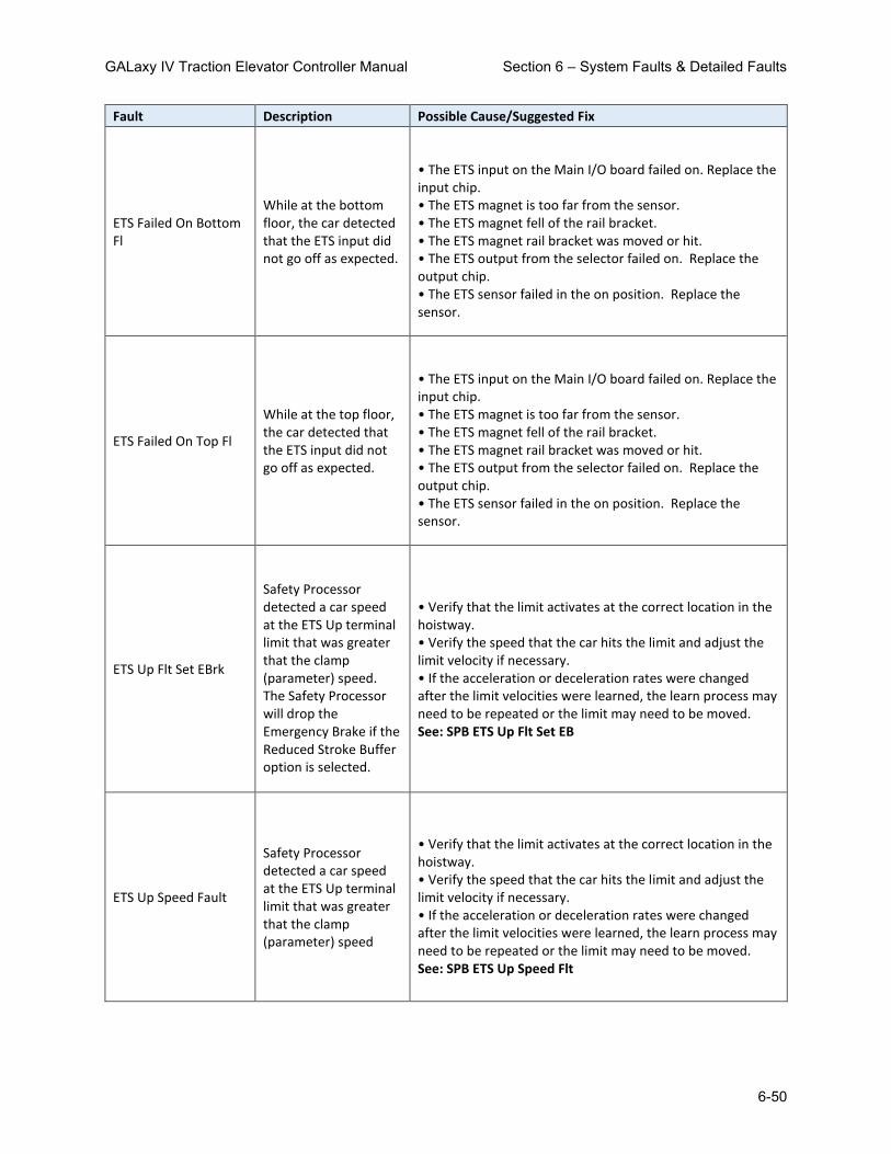
GALaxy IV Traction Elevator Controller Manual Section 6 – System Faults & Detailed Faults
6-50
Fault Description Possible Cause/Suggested Fix
ETS Failed On Bottom Fl
While at the bottom floor, the car detected that the ETS input did not go off as expected.
• The ETS input on the Main I/O board failed on. Replace the input chip. • The ETS magnet is too far from the sensor. • The ETS magnet fell of the rail bracket. • The ETS magnet rail bracket was moved or hit. • The ETS output from the selector failed on. Replace the output chip. • The ETS sensor failed in the on position. Replace the sensor.
ETS Failed On Top Fl
While at the top floor, the car detected that the ETS input did not go off as expected.
• The ETS input on the Main I/O board failed on. Replace the input chip. • The ETS magnet is too far from the sensor. • The ETS magnet fell of the rail bracket. • The ETS magnet rail bracket was moved or hit. • The ETS output from the selector failed on. Replace the output chip. • The ETS sensor failed in the on position. Replace the sensor.
ETS Up Flt Set EBrk
Safety Processor detected a car speed at the ETS Up terminal limit that was greater that the clamp (parameter) speed. The Safety Processor will drop the Emergency Brake if the Reduced Stroke Buffer option is selected.
• Verify that the limit activates at the correct location in the hoistway. • Verify the speed that the car hits the limit and adjust the limit velocity if necessary. • If the acceleration or deceleration rates were changed after the limit velocities were learned, the learn process may need to be repeated or the limit may need to be moved. See: SPB ETS Up Flt Set EB
ETS Up Speed Fault
Safety Processor detected a car speed at the ETS Up terminal limit that was greater that the clamp (parameter) speed
• Verify that the limit activates at the correct location in the hoistway. • Verify the speed that the car hits the limit and adjust the limit velocity if necessary. • If the acceleration or deceleration rates were changed after the limit velocities were learned, the learn process may need to be repeated or the limit may need to be moved. See: SPB ETS Up Speed Flt

GALaxy IV Traction Elevator Controller Manual Section 6 – System Faults & Detailed Faults
6-51
Fault Description Possible Cause/Suggested Fix
FDoor Close Cont Flt Door Close Contact safe fault
• After Controller was safe with doors, gate switch, door contacts and locks made and ready to run, a door contact input turned OFF.
FEP Fuse Blown Fault Fire/Emergency Circuit Fuse is Blown
• Short Circuit on the FEP Circuit.
FETST OFF Fault
Front Door Electric Eye Test Failed OFF. Output is turned on cause the electric eye outputs to controller input EE1 and EE2 to pulse.
• FETST output or FETST input failed in the off state. • Replace the FETST output chip. • Replace the FETST input chip.
FETST ON Fault
Front Door Electric Eye Test Failed ON. Output is turned on cause the electric eye outputs to controller input EE1 and EE2 to pulse.
• FETST output or FETST input failed in the on state. • Replace the FETST output chip. • Replace the FETST input chip.
Field Vars Deflt Ini
Field Variables Default Initialization. Field adjustable variables are being initialized for the first time.
• Job related parameters are invalid. This error occurs on the first time the GALX-1100 CPU board is being powered up.
Field Vars Relocated Field Variables Relocated.
The software has been updated to a newer version that required parameters to be relocated. This is normal and should only occur once. If an older version software is later installed, the job parameters may be lost.
Fire Fighter Stop Sw Fire Fighter Stop Sw
• Fire Fighter Stop switch is pulled. • Faulty wire connection in the Fire Fighter stop switch circuit.

GALaxy IV Traction Elevator Controller Manual Section 6 – System Faults & Detailed Faults
6-52
Fault Description Possible Cause/Suggested Fix
Fld Var Partial Init
Field variables partial table initialized. Controller did not see extended memory initialized before. It should occur once when updating controller software
• The software has been updated. This is normal and should only occur once. If fault constantly occurs please contact GAL.
Front Det Edge Fault Front Detector Edge Time-out
• The Electric Eye signal stayed on continuously for longer than the parameter 'EE Time-out' is set to.
FST I/O Failed Off
The FST input on the GALX-1102 board did not pick up when expected.
• Faulty FST output chip. Replace output chip. • Faulty FSTI input chip. Replace input chip.
FST I/O Failed On
The FST input on the GALX-1102 board did not drop out when expected.
• Faulty FST output chip. Replace output chip. • Faulty FSTI input chip. Replace input chip.
FSTP I/O Failed Off
The FSTP input on the GALX-1102 board did not pick up when expected.
• Faulty FST1 output chip. Replace output chip. • Faulty FSTI input chip. Replace input chip.
FSTP I/O Failed On
The FSTP input on the GALX-1102 board did not drop out up when expected
• Faulty FST1 output chip. Replace output chip. • Faulty FSTI input chip. Replace input chip.
FVARS Backup Init
Field Variables Backup Init. Field variables backed up for the first time.
Older software did not backup the field variables. When new software replaces the older software this error will be displayed. If this error occurs every time the CPU powers up, then the CPU may be faulty and should be replaced.

GALaxy IV Traction Elevator Controller Manual Section 6 – System Faults & Detailed Faults
6-53
Fault Description Possible Cause/Suggested Fix
FVARS Backup Tbl Cksm
Field Variables Backup Table Checksum Error. The verification checksum for the backup field variable table has failed.
During power outages or brown-outs, enough noise can be generated on the 5V DC supply to cause an error in reading the field variables table on power up. For this reason we keep the data in two separate tables. If only one table checksum error occurs, then valid data will be restored. No action is required.
FVARS Backup Tbl Err
Field Variables Backup Table Error. The field variables from the backup MRAM table does not match the variable read into memory from the main MRAM table.
Most likely, if this error occurs, other FVARS errors will also occur. A once-in-a-while occurrence of this error can be ignored if it is not accompanied by the following errors: FVARS Both Tbl Chksum error or FVARS Tbl Chksum Error. If either error occurs with this error, the main CPU board should be replaced.
FVARS Both Tbl Chksum
Field Variables Both Table Checksum Table error. The verification checksum for both the main field variable table and backup table has failed.
Field Variable data is stored in two separate MRAM tables and a checksum of each table is stored in a separate location. When the system powers up, the checksum of each table is verified. If one table fails verification, the field variables are copied from the table that passed verification and then both tables are updated with valid data. If both checksum verifications fail, data is copied from the main table and an error code is displayed. • If this fault occurs, replace the main CPU board.
FVARS Tbl Chksum Err
Field Variables Table Checksum Error. The verification checksum for the main field variable table has failed.
During power outages or brown-outs, enough noise can be generated on the 5V DC supply to cause an error in reading the field variables table on power up. For this reason we keep the data in two separate tables. If only one table checksum error occurs, then valid data will be restored. No action is required.
Gate Switch Fault The Gate Switch failed on while the door was open.
• Gate switch not adjusted properly. • GS input failed on. Replace GS input on the GALX-1102 board.

GALaxy IV Traction Elevator Controller Manual Section 6 – System Faults & Detailed Faults
6-54
Fault Description Possible Cause/Suggested Fix
Gate/Lock Byp Sw Flt
The gate or lock bypass switch was on while the car was NOT on car top inspection.
• Gate or Lock bypass switch on the controller the GALX-1102 board is in the on position. • Gate or Lock bypass input failed on. Replace GBP OR LBP input chip on 1102 board.
GOV Overspeed Trip
Governor Overspeed Trip. An ascending overspeed fault occurred from the governor switch opening. This fault sets the gripper or emergency brake.
• Verify that the car runs controlled on inspection. If not, increase the response, inertia or gains of the drive. • Verify that the car runs controlled on automatic. The car may be overshooting the roll into top speed. If so, increase the response, inertia or gains of the drive. • Verify that the car runs properly with full load. If not, adjust the drive.
Governor Switch Flt Governor Switch Tripped.
• Verify that the governor switch is set properly. • Verify that the drive is setup properly and that the car does not overspeed.
GOVRi Input On Fault GOVRi input failed on.
• The GOVRi input chip failed. Replace the chip. • The governor reset switch is stuck on. • The GOVRi input is jumped on.
GRCAN Device Fault Device on the Group CAN Port has a Fault
• Look at the details of the fault. The device name and the error code that caused the fault are listed. • Look up the fault code for the device for debugging information.
GRCAN Device Reset Device on the Group CAN Port has reset
• Look at the details of the fault. The device name and the error code that caused the fault are listed. • The device requested an initialization packet from the main CPU. Typically this occurs during power up or from a power cycle of the individual device. • Ignore the error if the controller power has been cycled. Otherwise, check the device communications and power connections.

GALaxy IV Traction Elevator Controller Manual Section 6 – System Faults & Detailed Faults
6-55
Fault Description Possible Cause/Suggested Fix
Gripper did not Pick
The rope gripper did not pick when the GR1 and GR2 relays were energized.
• Faulty wiring to the rope gripper. • Faulty GTS switch on rope gripper. Make sure that the switch opens and closes properly when the gripper is energized and dropped. • Faulty GTS input. Replace the GTS input chip.
Gripper Trip Fault
An overspeed or uncontrolled motion caused the rope gripper to trip.
• Check if the governor has tripped. • Make sure that the brake can hold the car.
Group Comm Loss
The car that was acting as the group car has stopped communicating.
• Faulty wiring from TX+/TX- from car to car. • Faulty U6 driver chip on the GALX-1100 CPU board (next to the connector for the group comm). Call GAL. • Noise on shield wire. Connect shield only on one end. • Noise on the communication wires. Run wires in separate conduit.
Grp Comm Config Err Group Comm configuration error.
• There is a device trying to get initialized that should not be on the bus • Check detailed fault data for 'dev' to identify board address
GRT1 input Off Fault
While testing the rope gripper relays, the contacts for GR1R or GR2R did not close or the GRT1 input failed off.
• Faulty GR1R or GR2R relays. Replace both GR1R and GR2R relays. • Faulty GRT1 input. Replace the GRT1 input chip.
GRT1 input On Fault
While testing the rope gripper relays, the contacts for GR1R or GR2R did not open or the GRT1 input failed on.
• Faulty GR1R or GR2R relays. Replace both GR1R and GR2R relays. • Faulty GRT1 input. Replace the GRT1 input chip.
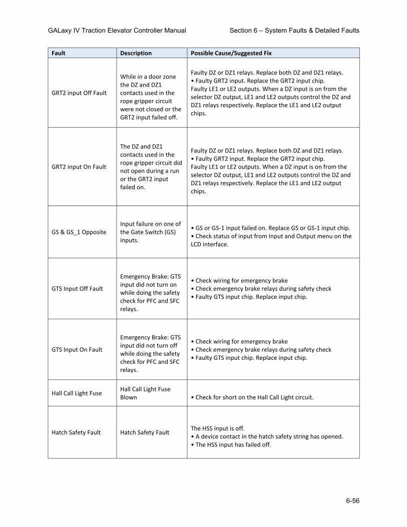
GALaxy IV Traction Elevator Controller Manual Section 6 – System Faults & Detailed Faults
6-56
Fault Description Possible Cause/Suggested Fix
GRT2 input Off Fault
While in a door zone the DZ and DZ1 contacts used in the rope gripper circuit were not closed or the GRT2 input failed off.
Faulty DZ or DZ1 relays. Replace both DZ and DZ1 relays. • Faulty GRT2 input. Replace the GRT2 input chip. Faulty LE1 or LE2 outputs. When a DZ input is on from the selector DZ output, LE1 and LE2 outputs control the DZ and DZ1 relays respectively. Replace the LE1 and LE2 output chips.
GRT2 input On Fault
The DZ and DZ1 contacts used in the rope gripper circuit did not open during a run or the GRT2 input failed on.
Faulty DZ or DZ1 relays. Replace both DZ and DZ1 relays. • Faulty GRT2 input. Replace the GRT2 input chip. Faulty LE1 or LE2 outputs. When a DZ input is on from the selector DZ output, LE1 and LE2 outputs control the DZ and DZ1 relays respectively. Replace the LE1 and LE2 output chips.
GS & GS_1 Opposite Input failure on one of the Gate Switch (GS) inputs.
• GS or GS-1 input failed on. Replace GS or GS-1 input chip. • Check status of input from Input and Output menu on the LCD interface.
GTS Input Off Fault
Emergency Brake: GTS input did not turn on while doing the safety check for PFC and SFC relays.
• Check wiring for emergency brake • Check emergency brake relays during safety check • Faulty GTS input chip. Replace input chip.
GTS Input On Fault
Emergency Brake: GTS input did not turn off while doing the safety check for PFC and SFC relays.
• Check wiring for emergency brake • Check emergency brake relays during safety check • Faulty GTS input chip. Replace input chip.
Hall Call Light Fuse Hall Call Light Fuse Blown
• Check for short on the Hall Call Light circuit.
Hatch Safety Fault Hatch Safety Fault
The HSS input is off. • A device contact in the hatch safety string has opened. • The HSS input has failed off.

GALaxy IV Traction Elevator Controller Manual Section 6 – System Faults & Detailed Faults
6-57
Fault Description Possible Cause/Suggested Fix
HC Com Device Reset
Serial Hall Call board reset unexpectedly. Usually caused by loss of power to the individual board.
• Usually caused by loss of power to the individual board. • Faulty power connection to board. • Fault hall call board.
HC DrvBd Rx from Bot Not receiving packets from the bottom station
• Cable is bad or disconnected • Cables going to wrong port (i.e., switched TO ABOVE and TO BELOW) • Transmitter from device above or below is bad, check faults for that device. • Receiver on board is bad – replace device
HC DrvBd Tx to Bot
Can't internally read information from Transmitter to bottom station
• Cable connecting two devices could be flip-flopped (i.e., gray wire goes from pin 1 on one end to pin 8 on the other end). Disconnect cable, and if fault changes to Rx Fault, the problem is the cable. • Cables going to wrong port (i.e., switched TO ABOVE and TO BELOW) • Transmitter is bad – replace the Device.
HC DvrBd Rx from Top Not receiving packets from the top station.
• Cable is bad or disconnected • Cables going to wrong port (i.e., switched TO ABOVE and TO BELOW) • Transmitter from device above or below is bad, check faults for that device. • Receiver on board is bad – replace device
HC DvrBd Too Few Dev
Too Few stations detected based on configuration – will only trigger if loop is closed (i.e. will not trigger if device #5 is not functioning, causing driver to establish communication with all but one station.)
• Check configuration and number of stations

GALaxy IV Traction Elevator Controller Manual Section 6 – System Faults & Detailed Faults
6-58
Fault Description Possible Cause/Suggested Fix
HC DvrBd TooMany Dev
Too Many stations detected based on configuration.
• Check configuration and number of stations
HC DvrBd Tx to Top
Can't internally read information from Transmitter to top station.
• Cable connecting two devices could be flip-flopped (i.e., gray wire goes from pin 1 on one end to pin 8 on the other end). Disconnect cable, and if fault changes to Rx Fault, the problem is the cable. • Cables going to wrong port (i.e., switched TO ABOVE and TO BELOW) • Transmitter is bad – replace the Device.
HC Fuse Blown Fault The HC input is off. No power on HC.
• Make sure that the hall call power for each car is in phase. During a power up for car 1 while car 2 is powering the hall call power could cause a momentary short if the hall call power for each car is not in phase. • Short circuit in the hall call lighting circuitry.
HCB Ax Dn Input Ovld HCB Aux Down input overload
• Controller detected overload in the input from the Aux terminal at the station. To identify fault device refer to Detailed Fault Log 'dev' and 'dv2' will provide address for Serial Driver address and Station where the fault was generated.
HCB Ax Up Input Ovld HCB Aux Up input overload
• Controller detected overload in the input from the Aux terminal at the station. To identify fault device refer to Detailed Fault Log 'dev' and 'dv2' will provide address for Serial Driver address and Station where the fault was generated.
HCB Device Comm Loss
The Driver does not see this HCB device
• Comm faults above and below a device – check wiring • Board not powering up – check 24VAC and MCU on device • Fuses blown on driver

GALaxy IV Traction Elevator Controller Manual Section 6 – System Faults & Detailed Faults
6-59
Fault Description Possible Cause/Suggested Fix
HCB Device Reset The HCB has just comeback online
• Fixed previous problem. There is a power/communication problem, where the board is either resetting (power) or temporarily losing communication on both ports.
HCB Dn FET Open HCB fet open down • Replace GALX-1054AN
HCB Dn FET Short HCB fet short down • Replace GALX-1054AN
HCB Dn Input Ovrload HCB Down input overload
• Controller detected overload in the input from the LED board at the station. To identify fault device refer to Detailed Fault Log 'dev' and 'dv2' will provide address for Serial Driver address and Station where the fault was generated.
HCB Dn LED Open HCB led open down
• Make Sure there is a GALX-1056AN attached to the proper connector (Up LED always attached to CN5, Down LED attached to CN5 if only down call at that station (like the top floor), otherwise attached via ribbon at CN6. • Replace GALX-1056AN for the associated up or down call.
HCB Dn LED Short HCB led short down
• Make Sure there is a GALX-1056AN attached to the proper connector (Up LED always attached to CN5, Down LED attached to CN5 if only down call at that station (like the top floor), otherwise attached via ribbon at CN6. • Replace GALX-1056AN for the associated up or down call.
HCB FET Open Blue Dn HCB fet open blue down
• Replace the GALX-1093AN board – dev / dev 2 can pinpoint which 1093 is at fault.
HCB FET Open Blue Up HCB fet open blue up • Replace the GALX-1093AN board – dev / dev 2 can pinpoint which 1093 is at fault.

GALaxy IV Traction Elevator Controller Manual Section 6 – System Faults & Detailed Faults
6-60
Fault Description Possible Cause/Suggested Fix
HCB FET Open Grn Dn HCB fet open green down
• Replace the GALX-1093AN board – dev / dev 2 can pinpoint which 1093 is at fault.
HCB FET Open Grn Up HCB fet open green up • Replace the GALX-1093AN board – dev / dev 2 can pinpoint which 1093 is at fault.
HCB FET Open Red Dn HCB fet open red down • Replace the GALX-1093AN board – dev / dev 2 can pinpoint which 1093 is at fault.
HCB FET Open Red Up HCB fet short red up • Replace the GALX-1093AN board – dev / dev 2 can pinpoint which 1093 is at fault.
HCB FET Short Blu Dn HCB fet short blue down
• Replace the GALX-1093AN board – dev / dev 2 can pinpoint which 1093 is at fault.
HCB FET Short Blu Up HCB fet short blue up • Replace the GALX-1093AN board – dev / dev 2 can pinpoint which 1093 is at fault.
HCB FET Short Grn Dn HCB fet short green down
• Replace the GALX-1093AN board – dev / dev 2 can pinpoint which 1093 is at fault.
HCB FET Short Grn Up HCB fet short green up • Replace the GALX-1093AN board – dev / dev 2 can pinpoint which 1093 is at fault.
HCB FET Short Red Dn HCB fet short red down
• Replace the GALX-1093AN board – dev / dev 2 can pinpoint which 1093 is at fault.
HCB FET Short Red Up HCB fet short red up • Replace the GALX-1093AN board – dev / dev 2 can pinpoint which 1093 is at fault.
HCB Invalid Floor HCB has invalid floor • This fault is only intended for internal use to identify floors that need to be skipped in diagnostics. It should never occur

GALaxy IV Traction Elevator Controller Manual Section 6 – System Faults & Detailed Faults
6-61
Fault Description Possible Cause/Suggested Fix
HCB LED Open Blue Dn
HCB led open blue down
• Make Sure there is a GALX-1056AN attached to the proper connector (Up LED always attached to CN5, Down LED attached to CN5 if only down call at that station (like the top floor), otherwise attached via ribbon at CN6. • Replace GALX-1056AN for the associated up or down call.
HCB LED Open Blue Up
HCB led open blue up
• Make Sure there is a GALX-1056AN attached to the proper connector (Up LED always attached to CN5, Down LED attached to CN5 if only down call at that station (like the top floor), otherwise attached via ribbon at CN6. • Replace GALX-1056AN for the associated up or down call.
HCB LED Open Grn Dn HCB led open green down
• Make Sure there is a GALX-1056AN attached to the proper connector (Up LED always attached to CN5, Down LED attached to CN5 if only down call at that station (like the top floor), otherwise attached via ribbon at CN6. • Replace GALX-1056AN for the associated up or down call.
HCB LED Open Grn Up HCB led open green up
• Make Sure there is a GALX-1056AN attached to the proper connector (Up LED always attached to CN5, Down LED attached to CN5 if only down call at that station (like the top floor), otherwise attached via ribbon at CN6. • Replace GALX-1056AN for the associated up or down call.
HCB LED Open Red Dn HCB led open red down
• Make Sure there is a GALX-1056AN attached to the proper connector (Up LED always attached to CN5, Down LED attached to CN5 if only down call at that station (like the top floor), otherwise attached via ribbon at CN6. • Replace GALX-1056AN for the associated up or down call.

GALaxy IV Traction Elevator Controller Manual Section 6 – System Faults & Detailed Faults
6-62
Fault Description Possible Cause/Suggested Fix
HCB LED Open Red Up HCB led short red up
• Make Sure there is a GALX-1056AN attached to the proper connector (Up LED always attached to CN5, Down LED attached to CN5 if only down call at that station (like the top floor), otherwise attached via ribbon at CN6. • Replace GALX-1056AN for the associated up or down call.
HCB LED Short Blu Dn HCB led short blue down
• Make Sure there is a GALX-1056AN attached to the proper connector (Up LED always attached to CN5, Down LED attached to CN5 if only down call at that station (like the top floor), otherwise attached via ribbon at CN6. • Replace GALX-1056AN for the associated up or down call.
HCB LED Short Blu Up HCB led short blue up
• Make Sure there is a GALX-1056AN attached to the proper connector (Up LED always attached to CN5, Down LED attached to CN5 if only down call at that station (like the top floor), otherwise attached via ribbon at CN6. • Replace GALX-1056AN for the associated up or down call.
HCB LED Short Grn Dn HCB led short green down
• Make Sure there is a GALX-1056AN attached to the proper connector (Up LED always attached to CN5, Down LED attached to CN5 if only down call at that station (like the top floor), otherwise attached via ribbon at CN6. • Replace GALX-1056AN for the associated up or down call.
HCB LED Short Grn Up HCB led short green up
• Make Sure there is a GALX-1056AN attached to the proper connector (Up LED always attached to CN5, Down LED attached to CN5 if only down call at that station (like the top floor), otherwise attached via ribbon at CN6. • Replace GALX-1056AN for the associated up or down call.

GALaxy IV Traction Elevator Controller Manual Section 6 – System Faults & Detailed Faults
6-63
Fault Description Possible Cause/Suggested Fix
HCB LED Short Red Dn HCB led short red down
• Make Sure there is a GALX-1056AN attached to the proper connector (Up LED always attached to CN5, Down LED attached to CN5 if only down call at that station (like the top floor), otherwise attached via ribbon at CN6. • Replace GALX-1056AN for the associated up or down call.
HCB LED Short Red Up HCB led short red up
• Make Sure there is a GALX-1056AN attached to the proper connector (Up LED always attached to CN5, Down LED attached to CN5 if only down call at that station (like the top floor), otherwise attached via ribbon at CN6. • Replace GALX-1056AN for the associated up or down call.
HCB Low Supply Volt Hall call board has low supply voltage
• Low voltage at Hall call device level. To identify fault device refer to Detailed Fault Log 'dev' and 'dv2' will provide address for Serial Driver address and Station where the fault was generated.
HCB No Dn LED Board HCB No Down Led Board Detected
• HCB board could not detect an LED board • Replace LED board (GALX-1085AN)
HCB No Up LED Board HCB No Up Led Board Detected
• HCB board could not detect an LED board • Replace LED board (GALX-1085AN)
HCB Rx from above fl HCB Rx fault from above floor
• Receiver on board is bad – replace device • Cable is bad or disconnected • Cables going to wrong port (i.e., switched to above and to below) • Transmitter from device above is bad.
HCB Rx from below fl HCB Rx fault from below floor
• Receiver on board is bad – replace device • Cable is bad or disconnected • Cables going to wrong port (i.e., switched to above and to below) • Transmitter from device below is bad.

GALaxy IV Traction Elevator Controller Manual Section 6 – System Faults & Detailed Faults
6-64
Fault Description Possible Cause/Suggested Fix
HCB Stuck Dn Button HCB stuck button down
• Button is physically stuck – fix button • Input is stuck on or shorted – replace device
HCB Stuck Up Button HCB stuck button up • Button is physically stuck – fix button • Input is stuck on or shorted – replace device
HCB Tx to above fl
Can't internally read information from Transmitter to device above
• Cable connecting two devices could be flip-flopped (i.e., gray wire goes from pin 1 on one end to pin 8 on the other end). Disconnect cable, and if fault changes to Rx Fault, the problem is the cable. • Transmitter is bad, Replace the Device
HCB Tx to below fl
Can't internally read information from Transmitter to device below
• Cable connecting two devices could be flip-flopped (i.e., gray wire goes from pin 1 on one end to pin 8 on the other end). Disconnect cable, and if fault changes to Rx Fault, the problem is the cable. • Transmitter is bad, Replace the Device
HCB Up FET Open HCB fet open up • Replace GALX-1054AN
HCB Up FET Short HCB fet short up • Replace GALX-1054AN
HCB Up Input Ovrload HCB Up input overload
• Controller detected overload in the input from the LED board at the station. To identify fault device refer to Detailed Fault Log 'dev' and 'dv2' will provide address for Serial Driver address and Station where the fault was generated.
HCB Up LED Open HCB Up LED open
• Make Sure there is a GALX-1056AN attached to the proper connector (Up LED always attached to CN5, Down LED attached to CN5 if only down call at that station (like the top floor), otherwise attached via ribbon at CN6. • Replace GALX-1056AN for the associated up or down call.

GALaxy IV Traction Elevator Controller Manual Section 6 – System Faults & Detailed Faults
6-65
Fault Description Possible Cause/Suggested Fix
HCB Up LED Short HCB Up LED shorted
• Make Sure there is a GALX-1056AN attached to the proper connector (Up LED always attached to CN5, Down LED attached to CN5 if only down call at that station (like the top floor), otherwise attached via ribbon at CN6. • Replace GALX-1056AN for the associated up or down call.
Hoist Motor Overload Hoist Motor Overload • Hoist Motor Overload signal tripped. Check Input chip for HMO input
Hoistway Default Ini
Hoistway Default Initialization. Hoistway values are being initialized for the first time.
• Job related hoistway setup information is invalid. This occurs on the first time the GALX-1100 CPU board is being powered up.
Hoistway Learn Fault
Car is on automatic and the hoistway has not been learned.
• Hoistway learn procedure needs to be performed. • Faulty ram-flash memory chip.
Hoistway Update Init
Hoistway Update Initialization. Table of door zone positions for hoistway used to update position count while traveling has been initialized for the first time.
• Job related hoistway setup information is invalid. This occurs on the first time the GALX-1100 CPU board is being powered up.
Hot Oil Fault Hot Oil Fault • Hydro only - Job is configured for hot oil detect. TPH input turned ON. Check for defective input.
INS DO Speed Fault Safety Processor Inspection Door Open Fault
• A door is open while running on inspection and the gate and locks are not being bypassed. The car will immediately shut down. See: SPB INS DO Speed Flt

GALaxy IV Traction Elevator Controller Manual Section 6 – System Faults & Detailed Faults
6-66
Fault Description Possible Cause/Suggested Fix
INS Speed Fault Safety Processor Inspection Speed Fault
• The car exceeded the INS Velocity adjustable variable while running on inspection. The car will immediately shut down. See: SPB INS Speed Fault
Inspection Input Flt
More than one input is on in the inspection string. The inspection string condition is also shown on the safety processor status screen.
• Faulty Top of Car inspection wiring. Verify voltage on CTA and ICA terminals when car top inspection switch is in the run position. Verify INS input when switch in the inspection position. • Verify that one and only one inspection string inputs is on: AUTO, MRI, INS, ICI and ACC. • Faulty inspection string input: AUTO, MRI, INS, ICI or ACC. Replace faulty input chip
Inspection Up/Dn Sw
An up or down inspection run input was on when first entering into inspection operation. This caused from a faulty inspection up or down switch or from someone holding the up or down run button when placing the car on inspection.
• Faulty inspection up or down input: IU, ID, MRIU, MRIU, BAD, BAU, TAD or TAU. Replace faulty input chip. • Faulty inspection wiring keeping an inspection up or down input on. • Placing the car on inspection while holding an up or down run button
Invald DT or DT1 Cnt
Invalid DT or DT1 Count. The position count for DT is greater than the count for DT1
• Invalid hoistway learn. Re-learn the hoistway. • The hoistway has not been learned. Learn the hoistway. • If this problem is not corrected with a hoistway learn, contact the factory
Invald FL Offset Cnt
Invalid Floor Offset Count. If the offset count is greater than 3 inches.
• The offset starts out at zero and is modified by the adjuster. This value should never be greater than 3 inches. • Encoder was changed from lower resolution to higher resolution which would cause the offset value to be out of range. Correct the offset value.

GALaxy IV Traction Elevator Controller Manual Section 6 – System Faults & Detailed Faults
6-67
Fault Description Possible Cause/Suggested Fix
Invalid DN or DT Cnt
Invalid DN or DT Count. The position count for DN is greater than the count for DT
• Invalid hoistway learn. Re-learn the hoistway. • The hoistway has not been learned. Learn the hoistway. • If this problem is not corrected with a hoistway learn, contact the factory
Invalid Fault Fault Code Greater than Table Value
• Can occur if device program version is newer that the controller program version and the device has a new fault that is not yet recorded in the controller program. Update controller software.
Invalid Fault Code Invalid Fault Code Device error not recognized by controller.
Invalid Floor Count
Invalid Floor Count. The floor count of the floor above must always be larger than the floor below. An above floor count was lower than the floor below in the floor hoistway table
• Invalid hoistway learn. Re-learn the hoistway. • The hoistway has not been learned. Learn the hoistway. • If this problem is not corrected with a hoistway learn, contact the factory
Invalid SEL Bot Cnt
Invalid Selector Bottom Count. (Tapeless selector) The bottom floor count is less then 4000. The count is initialized at 5000.
• Invalid hoistway learn. Re-learn the hoistway. • The hoistway has not been learned. Learn the hoistway. • If this problem is not corrected with a hoistway learn, contact the factory
Invalid SEL Top Cnt
Invalid Selector Top Count. The top selector count minus the bottom selector count is less than the number of floors times 30. The count averaged less than 30 counts per floor.
• Invalid hoistway learn. Re-learn the hoistway. • The hoistway has not been learned. Learn the hoistway. • If this problem is not corrected with a hoistway learn, contact the factory

GALaxy IV Traction Elevator Controller Manual Section 6 – System Faults & Detailed Faults
6-68
Fault Description Possible Cause/Suggested Fix
Invalid UT or UN Cnt
Invalid UT or UN Count. The position count for UT is greater than the count for UN
• Invalid hoistway learn. Re-learn the hoistway. • The hoistway has not been learned. Learn the hoistway. • If this problem is not corrected with a hoistway learn, contact the factory
Invld DT1 or DT2 Cnt
Invalid DT1 or DT2 Count. The position count for DT1 is greater than the count for DT2
• Invalid hoistway learn. Re-learn the hoistway. • The hoistway has not been learned. Learn the hoistway. • If this problem is not corrected with a hoistway learn, contact the factory
Invld DT2 or DT3 Cnt
Invalid DT2 or DT3 Count. The position count for DT2 is greater than the count for DT3
• Invalid hoistway learn. Re-learn the hoistway. • The hoistway has not been learned. Learn the hoistway. • If this problem is not corrected with a hoistway learn, contact the factory
Invld DT3 or DT4 Cnt
Invalid DT3 or DT4 Count. The position count for DT3 is greater than the count for DT4
• Invalid hoistway learn. Re-learn the hoistway. • The hoistway has not been learned. Learn the hoistway. • If this problem is not corrected with a hoistway learn, contact the factory
Invld DT4 or DT5 Cnt
Invalid DT4 or DT5 Count. The position count for DT4 is greater than the count for DT5
• Invalid hoistway learn. Re-learn the hoistway. • The hoistway has not been learned. Learn the hoistway. • If this problem is not corrected with a hoistway learn, contact the factory
Invld DT5 or DT6 Cnt
Invalid DT5 or DT6 Count. The position count for DT5 is greater than the count for DT6
• Invalid hoistway learn. Re-learn the hoistway. • The hoistway has not been learned. Learn the hoistway. • If this problem is not corrected with a hoistway learn, contact the factory

GALaxy IV Traction Elevator Controller Manual Section 6 – System Faults & Detailed Faults
6-69
Fault Description Possible Cause/Suggested Fix
Invld DZU or DZD Cnt
Invalid DZU or DZD Count. If the DZU count is greater than the floor position count or the DZD count is less than the floor position count, then this error is declared.
• Invalid hoistway learn. Re-learn the hoistway. • The hoistway has not been learned. Learn the hoistway. • If this problem is not corrected with a hoistway learn, contact the factory
Invld UT1 or UT Cnt
Invalid UT1 or UT Count. The position count for UT1 is greater than the count for UT
• Invalid hoistway learn. Re-learn the hoistway. • The hoistway has not been learned. Learn the hoistway. • If this problem is not corrected with a hoistway learn, contact the factory
Invld UT2 or UT1 Cnt
Invalid UT2 or UT1 Count. The position count for UT2 is greater than the count for UT1
• Invalid hoistway learn. Re-learn the hoistway. • The hoistway has not been learned. Learn the hoistway. • If this problem is not corrected with a hoistway learn, contact the factory
Invld UT3 or UT2 Cnt
Invalid UT3 or UT2 Count. The position count for UT3 is greater than the count for UT2
• Invalid hoistway learn. Re-learn the hoistway. • The hoistway has not been learned. Learn the hoistway. • If this problem is not corrected with a hoistway learn, contact the factory
Invld UT4 or UT3 Cnt
Invalid UT4 or UT3 Count. The position count for UT4 is greater than the count for UT3
• Invalid hoistway learn. Re-learn the hoistway. • The hoistway has not been learned. Learn the hoistway. • If this problem is not corrected with a hoistway learn, contact the factory
Invld UT5 or UT4 Cnt
Invalid UT5 or UT4 Count. The position count for UT5 is greater than the count for UT4
• Invalid hoistway learn. Re-learn the hoistway. • The hoistway has not been learned. Learn the hoistway. • If this problem is not corrected with a hoistway learn, contact the factory

GALaxy IV Traction Elevator Controller Manual Section 6 – System Faults & Detailed Faults
6-70
Fault Description Possible Cause/Suggested Fix
Invld UT6 or UT5 Cnt
Invalid UT6 or UT5 Count. The position count for UT6 is greater than the count for UT5
• Invalid hoistway learn. Re-learn the hoistway. • The hoistway has not been learned. Learn the hoistway. • If this problem is not corrected with a hoistway learn, contact the factory
Invld Top Floor Cnt Invalid Top Floor Count. The top floor count is zero.
• Invalid hoistway learn. Re-learn the hoistway. • The hoistway has not been learned. Learn the hoistway. • If this problem is not corrected with a hoistway learn, contact the factory
IO Fault
Safety Processor I/O Fault. An input is on in error. The Elevator Status display will show the I/O error.
• All inspection inputs and the auto input are off. • More than one inspection or auto input is on at the same time. • A bypass input is on while the car is not on Car top inspection. • Both up and down run output from the main CPU are on at the same time. • The car will not be able to run until the error is cleared. See: SPB IO Fault
KEB Not In Run Mode
KEB drive not in run mode. We need to verify that the drive is in Run Mode before we do every Run.
• LF.03 was not set to zero with the car in automatic. If the error occurred while troubleshooting disregard error. If it happens when in service, check drive for possible cause of this parameter not being set properly.
L1 Low Line Voltage L1 Line Voltage Low • Voltage Sensor Board Related. Voltage being monitored on L1 dropped below the setting for parameter ' Low Line Volt '
L2 Low Line Voltage L2 Line Voltage Low • Voltage Sensor Board Related. Voltage being monitored on L2 dropped below the setting for parameter ' Low Line Volt '
L3 Low Line Voltage L3 Line Voltage Low • Voltage Sensor Board Related. Voltage being monitored on L3 dropped below the setting for parameter ' Low Line Volt '

GALaxy IV Traction Elevator Controller Manual Section 6 – System Faults & Detailed Faults
6-71
Fault Description Possible Cause/Suggested Fix
Learn HW Safe Fault
Part of the safety string open while in automatic learn hoistway mode
• Check for possible faults on the safety processor or drive • Door locks, gate switch or contacts open while in motion
Learn HW Stall Fault
Car timed out while learning hoistway in auto
• Increase field variable 'Hoistway Learn Stall Time' and try again
Lev Flt Set EM Brake Emergency brake set from leveling fault
• A leveling fault occurred and the parameter 'Adjustable Options->Car Options->Leveling Fault = ' is set so it trips the Rope Gripper/Emergency Brake
Lev Flt Set Gripper Gripper set from leveling fault
A leveling fault occurred and the field variable 'Adjustable Options->Car Options->Leveling Fault = ' is set to 1=Set Grip/EB so it trips the Rope Gripper/Emergency Brake. Verify that the car relevels properly. • Adjust car leveling speed. • Adjust drive response. • Adjust relevel brake parameters. • See Leveling Fault.
LEV Speed Fault
Safety Processor I/O Fault. An input is on in error. The Elevator Status display will show the I/O error.
• Car was traveling at a speed greater than the leveling speed parameter in the door zone with the door open. • Leveling Vel adjustable variable may be set too low. See: SPB Lev Speed Fault
Level Stop Cnt Fault
Leveling stop fault occurred from incorrect count. As the car was leveling off the pulses, UL or DL turned off.
• Floor offset value set too high. Increase dead zone when the car is configured to stop on the pulses instead of just the magnet • Ensure outer sensors are set no more than 7.5 inches apart

GALaxy IV Traction Elevator Controller Manual Section 6 – System Faults & Detailed Faults
6-72
Fault Description Possible Cause/Suggested Fix
Leveling Fault
Leveling Fault. When the controller attempted to drop the brake, the car moved out of the dead level. The leveling fault count was incremented. If this occurs more times than the adjustable variable 'Level Fault Cnt' then this error is declared.
• Brake is dropping too slowly. Adjust the drop of the brake. The drive is not holding zero speed. Run the car on inspection at 5fpm and while running change the inspection speed to zero. The car should stop and hold zero. • The response is not high enough on the drive. • Brake contactor is not dropping properly.
Leveling Tim-out Flt Leveling Time-out Fault
• Car overshot the floor and continued leveling. • Car targeted floor too soon and was creeping to the floor in leveling. • Check for causes of invalid pulse counts or invalid floor positions • Invalid floor position preset • Faulty encoder connection • Faulty encoder wiring
Limit Opp Dir Flt
Car hit limits in wrong direction. In a single Run every Limit switch signal should only change state once or not change at all. If car was travelling down and an Up Terminal Slowdown switch goes LOW after we go in motion we will detect that as a fault. This fault will drop the gripper or emergency brake. Disable this fault with field variable Lim Dir Flt Dis set to 1=Disabled.
• If Controller is not really faulting, check that Slowdowns are not at the same position as the dead level position. On Gearless jobs roll back could cause this extra change of state and therefore generate the fault. In that event reposition Terminal Slowdown by a couple of inches.

GALaxy IV Traction Elevator Controller Manual Section 6 – System Faults & Detailed Faults
6-73
Fault Description Possible Cause/Suggested Fix
Load Weigh Var Init Load weigher init
• Invalid load weigher table on power up. The load weigher table will be re-initialized to zero and the load weigher must be setup again. • If this error persist, the MRAM on the CPU board is faulty. Replace the CPU board. • Ignore this error if the load weigher is not being used.
Lobby Hall Call Fuse Lobby Call common fuse
• Lobby Common fuse blown. Check Input chip for LHC
Low Pressure Fault
Low Oil Pressure Fault. The low oil pressure switch has been activated.
• Low oil in the tank. • Faulty LOS input if low oil switch option is being used. Replace the LOS input chip. • Faulty Low Oil Switch. If low oil switch option is being used. • Verify the operation of the low oil switch.
Lowoil Switch Fault Low Oil Switch Fault. The low oil switch became active
Hydro. • Low oil in the hydraulic tank • Faulty wiring to the low oil input • Faulty low oil input. Replace LOS input.
LW Calibration Error
Load Weigher Calibration Error. The load weigher attempted to do an automatic calibration and could not be calibrated.
The load weigher device should be re-calibrated according to the manufacturer’s instructions.
LW Load Table Fault
A fault was detected in the Load weigher load tables. The empty load value was greater than or equal to the full load value at a valid floor.
• The load weigher might not be calibrated properly • The load weigher setup might have been interrupted before being completed. • Faulty load weigher device. • The load weigher device is not setup. • The load weigher data was not stored properly in the MRAM memory or was not read in properly on power up. • Invalid load weigher data read from or written to the SD card during an SD card job setup read.

GALaxy IV Traction Elevator Controller Manual Section 6 – System Faults & Detailed Faults
6-74
Fault Description Possible Cause/Suggested Fix
Machine Room Stop Sw
Machine Room Stop Switch is Opened
• Turn off the Machine Room Stop Switch. • Faulty Machine Room Stop Switch
MCA I/O Failed Off The MCA input or output has failed off.
• Faulty MCAi input chip. Replace input chip. • Faulty MCA output chip. Replace output chip.
MCA I/O Failed On The MCA input or output has failed on.
• Faulty MCAi input chip. Replace input chip. • Faulty MCA output chip. Replace output chip.
MCC I/O Failed Off The MCC input or output has failed off.
• Faulty MCCi input chip. Replace input chip. • Faulty MCC output chip. Replace output chip.
MCC I/O Failed On The MCC input or output has failed on.
• Faulty MCCi input chip. Replace input chip. • Faulty MCC output chip. Replace output chip.
MCX Off Fault The MCX contact is off when it is expected to be on.
• Faulty Auxiliary MC Contact. Replace the AUX contact block or wire to a spare contact (if available). • Faulty MCX input chip. Replace the input chip.
MCX On Fault The MCX contact is on when it is expected to be off.
• Faulty Auxiliary MC Contact. Replace the AUX contact block or wire to a spare contact (if available). • Faulty MCX input chip. Replace the input chip.
Mid Door Lock Fault The Middle Door Lock failed on while the door was open.
Faulty door lock. • Jumper on door lock circuit. • Door lock not adjusted properly. • Faulty wiring to DLM input. Faulty DLM and DLM-1 inputs (For this to occur both DLM and DLM-1 inputs must fail on). • DOL input failed. Replace DOL input chip. • Door operator open limit DOL is not adjusted properly
Motion Exit GTS Flt GTS Motion emergency exit
GTS input opened unexpectedly during a run. • Fault GTS switch on the rope gripper. Replace or correct the switch activation

GALaxy IV Traction Elevator Controller Manual Section 6 – System Faults & Detailed Faults
6-75
Fault Description Possible Cause/Suggested Fix
Motion Exit Ins Flt Emergency motion exit from inspection
Car was in motion before going in inspection Mode. Check for inspection inputs faulting out or Automatic input going low.
MRAM Hardware Fault
MRAM Fault The MRAM is tested on power up and has failed the test. Replace the CPU board.
MRAM Write Error
MRAM Write Error. After parameter data RAM has been modified through the user interface, the data is automatically written to MRAM for non-volatile storage. After the data is stored it is compared with the original parameter data. If it does not match a fault is recorded.
• This error should not occur. If it does occur, the problem is either a fault CPU board or MRAM chip. Replace the CPU board.
MRCAN Device Fault Device on the Machine Room CAN Port has a Fault
• Look at the details of the fault. The device name and the error code that caused the fault are listed. • Look up the fault code for the device for debugging information.
MRCAN Device Reset Device on the Machine Room CAN Port has reset
• Look at the details of the fault. The device name and the error code that caused the fault are listed. • The device requested an initialization packet from the main CPU. Typically this occurs during power up or from a power cycle of the individual device. • Ignore the error if the controller power has been cycled. Otherwise, check the device communications and power connections.
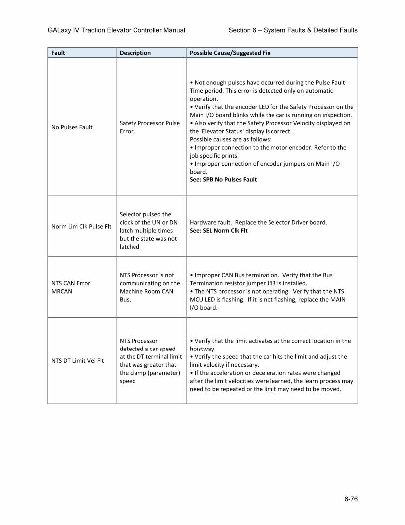
GALaxy IV Traction Elevator Controller Manual Section 6 – System Faults & Detailed Faults
6-76
Fault Description Possible Cause/Suggested Fix
No Pulses Fault Safety Processor Pulse Error.
• Not enough pulses have occurred during the Pulse Fault Time period. This error is detected only on automatic operation. • Verify that the encoder LED for the Safety Processor on the Main I/O board blinks while the car is running on inspection. • Also verify that the Safety Processor Velocity displayed on the 'Elevator Status' display is correct. Possible causes are as follows: • Improper connection to the motor encoder. Refer to the job specific prints. • Improper connection of encoder jumpers on Main I/O board. See: SPB No Pulses Fault
Norm Lim Clk Pulse Flt
Selector pulsed the clock of the UN or DN latch multiple times but the state was not latched
Hardware fault. Replace the Selector Driver board. See: SEL Norm Clk Flt
NTS CAN Error MRCAN
NTS Processor is not communicating on the Machine Room CAN Bus.
• Improper CAN Bus termination. Verify that the Bus Termination resistor jumper J43 is installed. • The NTS processor is not operating. Verify that the NTS MCU LED is flashing. If it is not flashing, replace the MAIN I/O board.
NTS DT Limit Vel Flt
NTS Processor detected a car speed at the DT terminal limit that was greater that the clamp (parameter) speed
• Verify that the limit activates at the correct location in the hoistway. • Verify the speed that the car hits the limit and adjust the limit velocity if necessary. • If the acceleration or deceleration rates were changed after the limit velocities were learned, the learn process may need to be repeated or the limit may need to be moved.

GALaxy IV Traction Elevator Controller Manual Section 6 – System Faults & Detailed Faults
6-77
Fault Description Possible Cause/Suggested Fix
NTS DT1 Limit Vel Flt
NTS Processor detected a car speed at the DT1 terminal limit that was greater that the clamp (parameter) speed
• Verify that the limit activates at the correct location in the hoistway. • Verify the speed that the car hits the limit and adjust the limit velocity if necessary. • If the acceleration or deceleration rates were changed after the limit velocities were learned, the learn process may need to be repeated or the limit may need to be moved.
NTS DT2 Limit Vel Flt
NTS Processor detected a car speed at the DT2 terminal limit that was greater that the clamp (parameter) speed
• Verify that the limit activates at the correct location in the hoistway. • Verify the speed that the car hits the limit and adjust the limit velocity if necessary. • If the acceleration or deceleration rates were changed after the limit velocities were learned, the learn process may need to be repeated or the limit may need to be moved.
NTS DT3 Limit Vel Flt
NTS Processor detected a car speed at the DT3 terminal limit that was greater that the clamp (parameter) speed
• Verify that the limit activates at the correct location in the hoistway. • Verify the speed that the car hits the limit and adjust the limit velocity if necessary. • If the acceleration or deceleration rates were changed after the limit velocities were learned, the learn process may need to be repeated or the limit may need to be moved.
NTS DT4 Limit Vel Flt
NTS Processor detected a car speed at the DT terminal limit that was greater that the clamp (parameter) speed
• Verify that the limit activates at the correct location in the hoistway. • Verify the speed that the car hits the limit and adjust the limit velocity if necessary. • If the acceleration or deceleration rates were changed after the limit velocities were learned, the learn process may need to be repeated or the limit may need to be moved.

GALaxy IV Traction Elevator Controller Manual Section 6 – System Faults & Detailed Faults
6-78
Fault Description Possible Cause/Suggested Fix
NTS DT5 Limit Vel Flt
NTS Processor detected a car speed at the DT5 terminal limit that was greater that the clamp (parameter) speed
• Verify that the limit activates at the correct location in the hoistway. • Verify the speed that the car hits the limit and adjust the limit velocity if necessary. • If the acceleration or deceleration rates were changed after the limit velocities were learned, the learn process may need to be repeated or the limit may need to be moved.
NTS DT6 Limit Vel Flt
NTS Processor detected a car speed at the DT6 terminal limit that was greater that the clamp (parameter) speed
• Verify that the limit activates at the correct location in the hoistway. • Verify the speed that the car hits the limit and adjust the limit velocity if necessary. • If the acceleration or deceleration rates were changed after the limit velocities were learned, the learn process may need to be repeated or the limit may need to be moved.
NTS Enc Opp Dir Flt
NTS Processor Encoder Direction from the selector or from the Motor Encoder is opposite of the UP or DNR run direction.
• Make sure that the elevator is running in the proper direction before attempting to correct this fault. • With an APS selector: The camera may not be adjusted properly and no direction is indicated. Verify that the camera is mounted correctly. The camera may not be communicating with the Selector. Use the Diagnostic menu to verify that the Selector is communicating with the camera. The NTS Processor may not be communicating on the Safety CAN bus. Using the Diagnostic menu, verify that the NTS processor is communicating to the Selector and the Safety Processor on the Safety CAN Bus. • With a Tapeless selector, the parameter for the NTS Processor Adjustable Variable -> Velocity Dir must be changed to the opposite value, i.e. 1 to a 0 or 0 to a 1.

GALaxy IV Traction Elevator Controller Manual Section 6 – System Faults & Detailed Faults
6-79
Fault Description Possible Cause/Suggested Fix
NTS Fault Dn Dir Run
NTS Fault Down Direction Run. The NTS processor hit a normal terminal limit going down at a velocity greater than the limit velocity parameter. This error is detected by the main CPU when the NTSDi input turns off during a run. Check the fault log for an MRCAN Device Fault showing the specific limit fault that occurred.
• If the NTSDi input does not turn on after the car stops, there may be a faulty NTSD input chip. Verify that the NTSD outputs are on and if so, replace the NTSDi input chip. • If the NTSD outputs are not on after the car stops, check the status of the output of NTSD on the Inputs and Outputs display for the NTS processor. If the LCD Display Interface shows that the NTS processor has the outputs on but the NTSD LEDs are not on, then there may be a faulty NTSD output chip. Replace the NTSD chip that has its corresponding LED off. • Verify that the limit activates at the correct location in the hoistway. • Verify the speed that the car hits the limit and adjust the limit velocity if necessary. • If the acceleration or deceleration rates were changed after the limit velocities were learned, the learn process may need to be repeated or the limit may need to be moved.
NTS Fault Up Dir Run
NTS Fault Up Direction Run. The NTS processor hit a normal terminal limit going up at a velocity greater than the limit velocity parameter. This error is detected by the main CPU when the NTSDi input turns off during a run. Check the fault log for an MRCAN Device Fault showing the specific limit fault that occurred.
• If the NTSDi input does not turn on after the car stops, there may be a faulty NTSD input chip. Verify that the NTSD outputs are on and if so, replace the NTSDi input chip. • If the NTSD outputs are not on after the car stops, check the status of the output of NTSD on the Inputs and Outputs display for the NTS processor. If the LCD Display Interface shows that the NTS processor has the outputs on but the NTSD LEDs are not on, then there may be a faulty NTSD output chip. Replace the NTSD chip that has its corresponding LED off. • Verify that the limit activates at the correct location in the hoistway. • Verify the speed that the car hits the limit and adjust the limit velocity if necessary. • If the acceleration or deceleration rates were changed after the limit velocities were learned, the learn process may need to be repeated or the limit may need to be moved.

GALaxy IV Traction Elevator Controller Manual Section 6 – System Faults & Detailed Faults
6-80
Fault Description Possible Cause/Suggested Fix
NTS Limit Vel Fault
NTS Limit Velocity Fault. During a limit learn, the velocity for one of the limits was recorded at a speed greater then the contract speed of the car. The velocity value of the limit is set to contract speed - 1.
• View all the limit velocity values of the NTS processor. If a limit velocity value is set to contract speed - 1, then the limit may need to be moved closer to the terminal landing so that the car hits the limit at a slower speed. NOTE: The controller sets the velocity at car speed -1 during the limit learn if something is not right with the limit. • Verify the velocity of the NTS processor during a normal run. • If the velocity value is correct, there could be enough of a delay that the car has started the slowdown but the velocity value has not been updated for the NTS processor. Try moving the limits closer to the terminal landing. • If using a tape selector, the velocity value that the NTS processor uses comes from the selector CPU. This value should also match the speed of the main CPU. Verify the proper pulse signals going into and out of the selector. • If using a tapeless selector, the NTS processor calculates the velocity from the motor encoder pulses. The velocity value will need to be adjusted to match the actual car speed. Increase the NTS RPM parameter value to reduce the NTS velocity or reduce the RPM to increase the NTS velocity.
NTS Low Velocity Flt NTS velocity < 25 fpm when car speed > 100 fpm for 3 seconds
• The NTS velocity is much lower than controller velocity during an automatic run. This fault will cause an emergency slowdown if the NTS velocity is low for 3 seconds. • The NTS processor get its velocity from the selector. Verify the NTS communications to the selector.
NTS SEL Comm Fault
NTS Processor recorded a communications fault with the Selector on the Safety CAN bus port.
• Faulty CAN bus wiring. • Termination resistors are usually placed at the far end of each BUS. Verify the placement of the Termination resistors. • Try moving the termination resistors to other locations. • Faulty device, replace board.
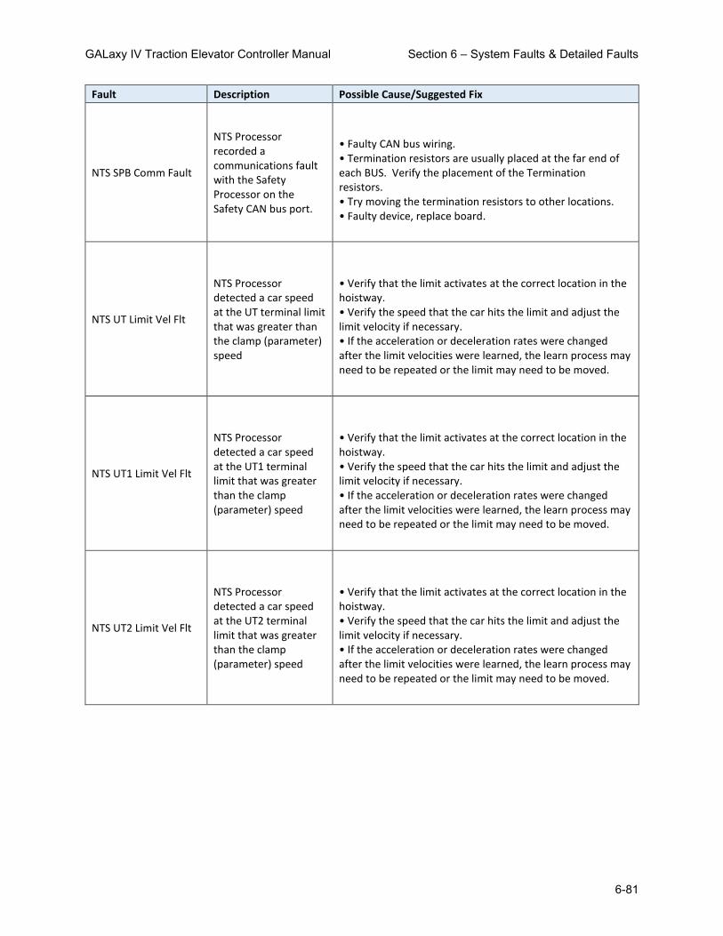
GALaxy IV Traction Elevator Controller Manual Section 6 – System Faults & Detailed Faults
6-81
Fault Description Possible Cause/Suggested Fix
NTS SPB Comm Fault
NTS Processor recorded a communications fault with the Safety Processor on the Safety CAN bus port.
• Faulty CAN bus wiring. • Termination resistors are usually placed at the far end of each BUS. Verify the placement of the Termination resistors. • Try moving the termination resistors to other locations. • Faulty device, replace board.
NTS UT Limit Vel Flt
NTS Processor detected a car speed at the UT terminal limit that was greater than the clamp (parameter) speed
• Verify that the limit activates at the correct location in the hoistway. • Verify the speed that the car hits the limit and adjust the limit velocity if necessary. • If the acceleration or deceleration rates were changed after the limit velocities were learned, the learn process may need to be repeated or the limit may need to be moved.
NTS UT1 Limit Vel Flt
NTS Processor detected a car speed at the UT1 terminal limit that was greater than the clamp (parameter) speed
• Verify that the limit activates at the correct location in the hoistway. • Verify the speed that the car hits the limit and adjust the limit velocity if necessary. • If the acceleration or deceleration rates were changed after the limit velocities were learned, the learn process may need to be repeated or the limit may need to be moved.
NTS UT2 Limit Vel Flt
NTS Processor detected a car speed at the UT2 terminal limit that was greater than the clamp (parameter) speed
• Verify that the limit activates at the correct location in the hoistway. • Verify the speed that the car hits the limit and adjust the limit velocity if necessary. • If the acceleration or deceleration rates were changed after the limit velocities were learned, the learn process may need to be repeated or the limit may need to be moved.

GALaxy IV Traction Elevator Controller Manual Section 6 – System Faults & Detailed Faults
6-82
Fault Description Possible Cause/Suggested Fix
NTS UT3 Limit Vel Flt
NTS Processor detected a car speed at the UT3 terminal limit that was greater than the clamp (parameter) speed
• Verify that the limit activates at the correct location in the hoistway. • Verify the speed that the car hits the limit and adjust the limit velocity if necessary. • If the acceleration or deceleration rates were changed after the limit velocities were learned, the learn process may need to be repeated or the limit may need to be moved.
NTS UT4 Limit Vel Flt
NTS Processor detected a car speed at the UT4 terminal limit that was greater than the clamp (parameter) speed
• Verify that the limit activates at the correct location in the hoistway. • Verify the speed that the car hits the limit and adjust the limit velocity if necessary. • If the acceleration or deceleration rates were changed after the limit velocities were learned, the learn process may need to be repeated or the limit may need to be moved.
NTS UT5 Limit Vel Flt
NTS Processor detected a car speed at the UT5 terminal limit that was greater than the clamp (parameter) speed
• Verify that the limit activates at the correct location in the hoistway. • Verify the speed that the car hits the limit and adjust the limit velocity if necessary. • If the acceleration or deceleration rates were changed after the limit velocities were learned, the learn process may need to be repeated or the limit may need to be moved.
NTS UT6 Limit Vel Flt
NTS Processor detected a car speed at the UT6 terminal limit that was greater than the clamp (parameter) speed
• Verify that the limit activates at the correct location in the hoistway. • Verify the speed that the car hits the limit and adjust the limit velocity if necessary. • If the acceleration or deceleration rates were changed after the limit velocities were learned, the learn process may need to be repeated or the limit may need to be moved.
NTS Vel Learn Fault Invalid NTS velocity while learning Hoistway or Limits
• NTS velocity did not match controller speed while learning hoistway or limits. The NTS processor get its velocity from the selector. • Verify communications to the selector.

GALaxy IV Traction Elevator Controller Manual Section 6 – System Faults & Detailed Faults
6-83
Fault Description Possible Cause/Suggested Fix
NTSD Comm Fault (From SEL)
Selector recorded a communications fault with the NTS Processor on the Safety CAN bus port.
• Faulty CAN bus wiring. • Termination resistors are usually placed at the far end of each BUS. Verify the placement of the Termination resistors. • Try moving the termination resistors to other locations. • Faulty device, replace board. See: SEL NTSD Comm Fault
NTSD Comm Fault (From SPB)
Safety Processor recorded a communications fault with the NTS Processor on the Safety CAN bus port.
• Faulty CAN bus wiring. • Termination resistors are usually placed at the far end of each BUS. Verify the placement of the Termination resistors. • Try moving the termination resistors to other locations. • Faulty device, replace board. See: SPB NTSD Comm Fault
Overspeed Fault
Car overspeed fault. If the car goes 15% over contract speed the fault will be logged and the car will do an emergency stop. This fault will set the gripper or emergency brake if parameter Car Options -> Griper/EBK Trip is set to +2.
Encoder PPR incorrectly set. Set to match the Drive’s Encoder Pulses. • Encoder RPM incorrectly set. Set to match the Motor’s RPM. The drive is not controlling the hoist machine motor. Check the response setting on the drive.
P Input Off Fault
The normally closed contacts on MC, BRK or RUN contactors did not drop.
• Not enough current draw through all three contacts. Place a 10K 3W resistor from the normally closed contact of RUN to GND. • Faulty normally closed contacts on MC, BK or RUN. Replace auxiliary contacts.
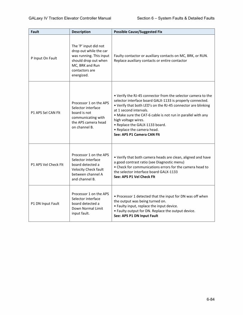
GALaxy IV Traction Elevator Controller Manual Section 6 – System Faults & Detailed Faults
6-84
Fault Description Possible Cause/Suggested Fix
P Input On Fault
The 'P' input did not drop out while the car was running. This input should drop out when MC, BRK and Run contactors are energized.
Faulty contactor or auxiliary contacts on MC, BRK, or RUN. Replace auxiliary contacts or entire contactor
P1 APS Sel CAN Flt
Processor 1 on the APS Selector interface board is not communicating with the APS camera head on channel B.
• Verify the RJ-45 connector from the selector camera to the selector interface board GALX-1133 is properly connected. • Verify that both LED’s on the RJ-45 connector are blinking at 1 second intervals. • Make sure the CAT-6 cable is not run in parallel with any high voltage wires. • Replace the GALX-1133 board. • Replace the camera head. See: APS P1 Camera CAN Flt
P1 APS Vel Check Flt
Processor 1 on the APS Selector interface board detected a Velocity Check fault between channel A and channel B.
• Verify that both camera heads are clean, aligned and have a good contrast ratio (see Diagnostic menu) • Check for communications errors for the camera head to the selector interface board GALX-1133 See: APS P1 Vel Check Flt
P1 DN Input Fault
Processor 1 on the APS Selector interface board detected a Down Normal Limit input fault.
• Processor 1 detected that the input for DN was off when the output was being turned on. • Faulty input, replace the input device. • Faulty output for DN. Replace the output device. See: APS P1 DN Input Fault

GALaxy IV Traction Elevator Controller Manual Section 6 – System Faults & Detailed Faults
6-85
Fault Description Possible Cause/Suggested Fix
P1 DZ Clip Fault
Processor 1 on the APS Selector interface board detected a door zone clip missing.
• Processor 1 detected a door zone clip missing at the same floor for three consecutive stops on channel B. • Verify that the door zone clip is roughly in the middle of channel A and B cameras. Place the clip in the proper position • If the clip is missing or broken, then replace the clip. • Go to the LCD Interface on the Main CPU and select the Dpy APS Sel Valid Clips menu under the Hoistway Tables menu. Under the display for ClpP1, a bit is set for each floor with a valid clip. Position the elevator at the floor that does not have the bit set and re-learn the floor position. See: APS P1 DZ Clip Fault
P1 DZ Input Fault
Processor 1 on the APS Selector interface board detected a door zone input fault.
• Processor 1 detected that the input for DZ was off when the output was being turned on. • Faulty input, replace the input device. • Faulty output for DZ. Replace the output device. See: APS P1 DZ Input Fault
P1 HoistW Floor Flt
Processor 1 on the APS Selector interface board has a hoistway learn flag set but does not have a valid floor table.
• If the installation process to learn all the floors is not complete then then ignore this error. • Complete the learn process. • Go to the LCD Interface on the Main CPU and select the Dpy APS Sel Valid Floors menu under the Hoistway Tables menu. Under the display for FLRP1, a bit is set for each valid floor. Position the elevator at the floor that does not have the bit set and re-learn the floor position. See: APS P1 HW Floor Flt
P1 HoistW Flr Cnt Er
Processor 1 on the APS Selector interface board has a floor count on a floor that is higher than the floor above.
• If the installation process to learn all the floors is not complete then then ignore this error. • Complete the learn process. • Go to the LCD Interface on the Main CPU and select the Dpy APS Sel Valid Floors menu under the Hoistway Tables menu. Under the display for FLRP1, a bit is set for each valid floor. Position the elevator at the floor that does not have the bit set and re-learn the floor position. See: APS P1 HW Flr Cnt Er

GALaxy IV Traction Elevator Controller Manual Section 6 – System Faults & Detailed Faults
6-86
Fault Description Possible Cause/Suggested Fix
P1 HoistW Flr Cnt=0
Processor 1 on the APS Selector interface board has a hoistway floor count value that is zero.
• If the installation process to learn all the floors is not complete then then ignore this error. • Complete the learn process. • Go to the LCD Interface on the Main CPU and select the Dpy APS Sel Valid Floors menu under the Hoistway Tables menu. Under the display for FLRP1, a bit is set for each valid floor. Position the elevator at the floor that does not have the bit set and re-learn the floor position. See: APS P1 HW Flr Cnt=0
P1 HoistW Setup Flt
Processor 1 on the APS Selector interface board has a hoistway setup fault.
• If the installation process to learn all the floors is not complete then then ignore this error. • Complete the learn process. • Go to the LCD Interface on the Main CPU and select the Dpy APS Sel Valid Floors menu under the Hoistway Tables menu. Under the display for FLRP1, a bit is set for each valid floor. Position the elevator at the floor that does not have the bit set and re-learn the floor position. See: APS P1 HW Setup Flt
P1 Hoistway Initialized
APS Selector Processor 2 Hoistway Initialized for first time.
• Should only occur on first time power up. • If this errors occurs on every power up then replace the board. See: APS P1 Hoistway Init
P1 Prog Cmd Diff Flt
Processor 1 returned a different command than what was sent from Processor 2.
•Verify that both MCU LEDs are blinking on the APS selector interface board. •Verify that the COMSPI LED driven by Processor 2 is blinking on the APS selector interface board. See: APS P1 Cmd Diff
P1 Prog Flr Cnt Diff
Processor 1 returned a different floor count than what was sent from Processor 2.
•Verify that both MCU LEDs are blinking on the APS selector interface board. •Verify that the COMSPI LED driven by Processor 2 is blinking on the APS selector interface board. See: APS P1 Prg Fl Cnt Dif

GALaxy IV Traction Elevator Controller Manual Section 6 – System Faults & Detailed Faults
6-87
Fault Description Possible Cause/Suggested Fix
P1 Prog Flr Diff Flt
Processor 1 returned a different floor number than what was sent from Processor 2.
•Verify that both MCU LEDs are blinking on the APS selector interface board. •Verify that the COMSPI LED driven by Processor 2 is blinking on the APS selector interface board. See: APS P1 Prog Flr Diff
P1 Prog Time-Out Flt
Processor 1 did not respond to Processor 2 within the required time during a floor count upload.
•Verify that both MCU LEDs are blinking on the APS selector interface board. •Verify that the COMSPI LED driven by Processor 2 is blinking on the APS selector interface board. See: APS P1 Prog Time-Out
P1 SS Input Fault
Processor 1 on the APS Selector interface board detected a Selector Safe input fault.
• Processor 1 detected that the input for SS (Note: This refers to SOK and not SOK1) was off when the output was being turned on. • Faulty input, replace the input device. • Faulty Selector Safe Relay. Replace the relay. See: APS P1 SS Input Fault
P1 SS Open Fault
Processor 1 on the APS Selector interface board detected that Selector Safe Relay output is open (off).
• Processor 1 detected that the input SS is off. • The device has a fault condition. Check other APS fault codes and correct the condition. • Faulty Selector Safe Relay. Replace the relay. See: APS P1 SS Open Fault
P1 UN Input Fault
Processor 1 on the APS Selector interface board detected a Up Normal Limit input fault.
• Processor 1 detected that the input for UN was off when the output was being turned on. • Faulty input, replace the input device. • Faulty output for UN. Replace the output device. See: APS P1 UN Input Fault
P2 APS Sel CAN Flt
Processor 2 on the APS Selector interface board is not communicating with the APS camera head on channel B.
• Verify the RJ-45 connector from the selector camera to the selector interface board GALX-1133 is properly connected. • Verify that both LED’s on the RJ-45 connector are blinking at 1 second intervals. • Make sure the CAT-6 cable is not run in parallel with any high voltage wires. • Replace the GALX-1133 board. • Replace the camera head. See: APS P2 Camera CAN Flt

GALaxy IV Traction Elevator Controller Manual Section 6 – System Faults & Detailed Faults
6-88
Fault Description Possible Cause/Suggested Fix
P2 DN Input Fault
Processor 2 on the APS Selector interface board detected a Down Normal Limit input fault.
• Processor 2 detected that the input for DN was off when the output was being turned on. • Faulty input, replace the input device. • Faulty output for DN. Replace the output device. See: APS P2 DN Input Fault
P2 DZ Clip Fault
Processor 2 on the APS Selector interface board detected a door zone clip missing.
• Processor 2 detected a door zone clip missing at the same floor for three consecutive stops on channel B. • Verify that the door zone clip is roughly in the middle of channel A and B cameras. Place the clip in the proper position • If the clip is missing or broken, then replace the clip. • Go to the LCD Interface on the Main CPU and select the Dpy APS Sel Valid Clips menu under the Hoistway Tables menu. Under the display for ClpP2, a bit is set for each floor with a valid clip. Position the elevator at the floor that does not have the bit set and re-learn the floor position. See: APS P2 DZ Clip Fault
P2 DZ Input Fault
Processor 2 on the APS Selector interface board detected a door zone input fault.
• Processor 2 detected that the input for DZ was off when the output was being turned on. • Faulty input, replace the input device. • Faulty output for DZ. Replace the output device. See: APS P2 DZ Input Fault
P2 FVars Initialized
APS Selector Processor 2 Field Variables Initialized for first time.
• Should only occur on first time power up. • If this errors occurs on every power up then replace the board. See: APS P2 Fvars Init

GALaxy IV Traction Elevator Controller Manual Section 6 – System Faults & Detailed Faults
6-89
Fault Description Possible Cause/Suggested Fix
P2 HoistW Floor Flt
Processor 2 on the APS Selector interface board has a hoistway learn flag set but does not have a valid floor table.
• If installation process to learn all the floors is not complete then then ignore this error. • Complete the learn process. • Go to the LCD Interface on the Main CPU and select the Dpy APS Sel Valid Floors menu under the Hoistway Tables menu. Under the display for FLRP2, a bit is set for each valid floor. Position the elevator at the floor that does not have the bit set and re-learn the floor position. See: APS P2 HW Floor Flt
P2 HoistW Flr Cnt Er
Processor 2 on the APS Selector interface board has a floor count on a floor that is higher than the floor above.
• If installation process to learn all the floors is not complete then then ignore this error. • Go to the LCD Interface on the Main CPU and select the Dpy APS Sel Valid Floors menu under the Hoistway Tables menu. A bit is set for each valid floor. Position the elevator at the floor that does not have the bit set and re-learn the floor position. See: APS P2 HW Flr Cnt Er
P2 HoistW Flr Cnt=0
Processor 2 on the APS Selector interface board has a hoistway floor count value that is zero.
• If installation process to learn all the floors is not complete then then ignore this error. • Complete the learn process. • Go to the LCD Interface on the Main CPU and select the Dpy APS Sel Valid Floors menu under the Hoistway Tables menu. Under the display for FLRP2, a bit is set for each valid floor. Position the elevator at the floor that does not have the bit set and re-learn the floor position. See: APS P2 HW Flr Cnt=0
P2 HoistW Setup Flt
Processor 2 on the APS Selector interface board has a hoistway setup fault.
• If the installation process to learn all the floors is not complete then then ignore this error. • Complete the learn process. • Go to the LCD Interface on the Main CPU and select the Dpy APS Sel Valid Floors menu under the Hoistway Tables menu. Under the display for FLRP2, a bit is set for each valid floor. Position the elevator at the floor that does not have the bit set and re-learn the floor position. See: APS P2 HW Setup Flt

GALaxy IV Traction Elevator Controller Manual Section 6 – System Faults & Detailed Faults
6-90
Fault Description Possible Cause/Suggested Fix
P2 Hoistway Initialized
APS Selector Processor 2 Hoistway Initialized for first time.
• Should only occur on first time power up. • If this errors occurs on every power up then replace the board. See: APS P2 Hoistway Init
P2 SP CAN Com Fault
Processor 2 on the APS Selector interface board is not communicating on the SPCAN bus with the NTS processor or the Safety Processor.
• Verify proper twisted pair wires to the SPCH and SPCL terminals on the GALX-1102 board. • Noise on the CAN Bus, verify that the shield wire is connected according to the job print. See: APS P2 SP CAN Com Flt
P2 SPI Com Fault
Processor 2 is not communicating through the SPI serial port with Processor 1 on the APS Selector interface board.
• Cycle the power on the board. If the problem persist, replace the APS board. See: APS P2 SPI Com Flt
P2 SS Input Fault
Processor 2 on the APS Selector interface board detected a Selector Safe input fault.
• Processor 2 detected that the input for SS (Note: This refers to SOK and not SOK1) was off when the output was being turned on. • Faulty input, replace the input device. • Faulty Selector Safe Relay. Replace the relay. See: APS P2 SS Input Fault
P2 SS Open Fault
Processor 2 on the APS Selector interface board detected that Selector Safe Relay output is open (off).
• Processor 2 detected that the input SS is off. • The device has a fault condition. Check other APS fault codes and correct the condition. • Faulty Selector Safe Relay. Replace the relay. See: APS P2 SS Open Fault
P2 UN Input Fault
Processor 2 on the APS Selector interface board detected a Up Normal Limit input fault.
• Processor 2 detected that the input for UN was off when the output was being turned on. • Faulty input, replace the input device. • Faulty output for UN. Replace the output device. See: APS P2 UN Input Fault

GALaxy IV Traction Elevator Controller Manual Section 6 – System Faults & Detailed Faults
6-91
Fault Description Possible Cause/Suggested Fix
PAL Error
The Safety PAL device did not pass the system test by the local CPU device.
• Faulty PAL or faulty board. Replace GALX-1102AN board. See: SAF PAL Error
PAL ETS Dn Spd Flt
The Safety PAL detected a car speed at the ETS Down terminal limit that was greater than the clamp speed.
• Verify that the limit activates at the correct location in the hoistway. • Verify the speed that the car hits the limit and adjust the limit velocity if necessary. • If the acceleration or deceleration rates were changed after the limit velocities were learned, the learn process may need to be repeated or the limit may need to be moved. • Verify the parameter setting in the Safety Processor for PAL ETS Dn Vel. See: SAF PAL ETS Dn Spd F
PAL ETS Up Spd Flt
The Safety PAL detected a car speed at the ETS Up terminal limit that was greater than the clamp speed.
• Verify that the limit activates at the correct location in the hoistway. • Verify the speed that the car hits the limit and adjust the limit velocity if necessary. • If the acceleration or deceleration rates were changed after the limit velocities were learned, the learn process may need to be repeated or the limit may need to be moved. • Verify the parameter setting in the Safety Processor for PAL ETS Up Vel. See: SAF PAL ETS Up Spd F
Parameter Setup Fault Safety Processor has a parameter setup fault
• Check the Safety Processor parameter settings for Buffer Type and Rear Door. Make sure they are set as required for the job. See: SPB Par Setup Fault
PFC Relay Failed Off PFC relay did not pick up as expected
• Faulty PFC output chip. Replace output chip. • Faulty PFC relay on main I/O Board GALX-1102. Replace PFC relay.
PFC Relay Failed On
PFC relay did not drop as expected when performing a SFC/PFC test.
• Faulty PFC output chip. Replace output chip. • Faulty PFC relay on main I/O Board GALX-1102. Replace PFC relay.

GALaxy IV Traction Elevator Controller Manual Section 6 – System Faults & Detailed Faults
6-92
Fault Description Possible Cause/Suggested Fix
PFC-SFC Test Lost DZ Lost DZ input when performing a SFC/PFC test.
• DZ output on selector board did not turn on. (Replace DZ output on selector driver board). One or both of the DZ sensors on the selector sensor board failed. Replace selector sensor board. • DZ input on the GALX-1102 board failed. Replace DZ input on the GALX-1102 board. • Check leveling magnet.
Pit Door Switch Flt Pit Door Switch Open • Verify that the pit door switch is closed. • Faulty wiring on the pit door switch circuit.
Pit Switch Fault Pit Switch Input Open • Verify that the pit switch is closed. • Faulty wiring on the pit switch circuit.
Pls Er 75% Top Speed
Pulse Error occurred while car is running greater then 75% of contract speed. The pulse counts have to change a minimum distance by the time the car reaches 75% of top speed.
• This error occurs if the car loses its pulse feedback from the encoder. • Make sure that the encoder is not slipping. • Check the encoder cable from the drive to the controller. • Also check the ribbon cable from the encoder isolation on the GALX-1102 board to the encoder input on the 1100 CPU board.
Position Fault
The Terminal limits do not match the car position (UT or DT is hit but the car position is not at the top or bottom floor).
• Car is out of step from faulty selector inputs. Check that the DZ, UL and DL selector inputs work properly at each floor. • Car missed a slowdown input magnet. Check that the US and DS selector inputs work properly prior to each landing (Hydro). • UT or DT input lost from the safety string being opened. • Improper adjustment of UT or DT limit switches
Possible DRV/SPB Er
The controller CPU lost the stop switch input, but has the SS and GTS inputs ON indicating that the drive or Safety Processor board has opened the safety string.
• View the faults on the Safety Processor display and debug from the fault code listed. • View the drive faults log or LED status and debug as directed from the drive manual.

GALaxy IV Traction Elevator Controller Manual Section 6 – System Faults & Detailed Faults
6-93
Fault Description Possible Cause/Suggested Fix
Power Up Reset
Whenever power is cycled on the controller this error will indicate that the controller CPU was reset
• This error code is normal for a power loss. If power was not lost and the CPU re-boots, verify the +5VDC on the CPU power connector reads in the range of 4.90 and 5.1 VDC. If out of range, adjust the 5VDC supply pot for the correct voltage.
Pulse Error > 75 fpm
Pulse count shows a travel distance less then 2 inches while the car demand velocity is greater than 75 fpm.
• Make sure that the encoder is not slipping. • Check the ribbon cable from the encoder isolation on the GALX-1102 Main I/O board to the encoder connection on the GALX-1100 CPU board. • Possible faulty encoder isolation on Main I/O board, faulty ribbon cable or faulty encoder CPU board.
Rail Lock Switch Flt Rail Lock Safety Switch Input is not on when expected.
• Check the rail lock contact on the COP board. • Faulty RLS input. Replace the input. • If there is no rail lock device (required for MRL elevators) this input may need to be jumped.
RCM / Lock Flt
Retiring Cam/Lock fault. Job has door contacts and door lock inputs as well as retiring cam output. Door locks are not coming on when trying to leave the floor.
• Door Contacts were already closed and the controller attempted to energize the retiring cam (RCM) several times and the door locks did not turn on. After 4 attempts, it will declare this fault. Check locks or retiring cam device.
RDoor Close Cont Flt Rear Door Close Contact safe fault
• After Controller was safe with doors, gate switch, door contacts and locks made and ready to run, a door contact input turned OFF.
Rear Bot Lock Fault
The Rear Bottom Door Lock failed on while the door was open (door on the rear door open limit [DOL]).
Faulty door lock. • Jumper placed on door lock circuit. • Rear door lock not adjusted properly. • Faulty wiring to DLB input. • Faulty DLB and DLB-1 inputs (For this to occur both DLB and DLB-1 inputs must fail on). • DOLR input failed. Replace DOLR input chip. • Rear door operator open limit is not adjusted properly

GALaxy IV Traction Elevator Controller Manual Section 6 – System Faults & Detailed Faults
6-94
Fault Description Possible Cause/Suggested Fix
Rear Det Edge Fault Rear Detector Edge Time-out
• The Rear Electric Eye signal stayed on continuously for longer than the parameter 'EE Time-out' is set to.
Rear Door Close Flt
The rear door did not reach the Rear Door Close Limit within the door close protection time.
• Rear Door Close Limit (DCLR) not adjusted properly. • Faulty Rear Door Close Limit (DCLR). Replace DCRL input. • Trash in door track preventing door from closing.
Rear Door Open Fault
The rear door did not reach the Rear Door Open Limit within the door open protection time.
• Rear Door Open Limit (DOLR) not adjusted properly. • Faulty Rear Door Open Limit (DOLR). Replace DOLR input.
Rear Gate Sw Fault The Rear Gate Switch failed on while the door was open.
• Rear Gate switch not adjusted properly. • RGS input failed on. Replace RGS input.
Rear Mid Lock Fault The Middle Door Lock failed on while the door was open.
Faulty door lock. • Jumper placed on door lock circuit. • Rear door lock not adjusted properly. • Faulty wiring to RLM input. • Faulty RLM and RLM-1 inputs (For this to occur both RLM and RLM-1 inputs must fail on). • DOLR input failed. Replace DOLR input chip. • Rear door operator open limit is not adjusted properly
Rear Top Lock Fault The Rear Top Door Lock failed on while the door was open.
Faulty door lock. • Jumper placed on door lock circuit. • Rear door lock not adjusted properly. • Faulty wiring to DLT input. Faulty DLT and DLT-1 inputs (For this to occur both DLT and DLT-1 inputs must fail on). • DOLR input failed. Replace DOLR input chip. • Rear door operator open limit is not adjusted properly

GALaxy IV Traction Elevator Controller Manual Section 6 – System Faults & Detailed Faults
6-95
Fault Description Possible Cause/Suggested Fix
Reset Brown-out Device Reset from Power Brown-out
• Fault is enabled from LCD Interface menu Adjustable Variables then select NTS Proc Adj Vars or SPB Proc Adj Vars and set parameter Debug Mode = 1. This is used for engineering debugging only.
Reset Debug Trap Device Reset from Debug Trap
• Fault is enabled from LCD Interface menu Adjustable Variables then select NTS Proc Adj Vars or SPB Proc Adj Vars and set parameter Debug Mode = 1. This is used for engineering debugging only.
Reset Fault
Anytime the system detects one of the following faults a reset fault is logged: • Power is cycled • Controller finds itself out of the door zone. • Binary input fault. • Terminal limits do not match the current position. • Car has been switched off of inspection. • After an open safety string has been closed.
• This fault is logged under normal conditions. Check the fault log for error that would indicate a fault condition prior to the reset fault.
Reset Idle Clock Device Reset from Clock Failure
• Fault is enabled from LCD Interface menu Adjustable Variables then select NTS Proc Adj Vars or SPB Proc Adj Vars and set parameter Debug Mode = 1. This is used for engineering debugging only.
Reset Illegal Op Code Device Reset from Illegal Operation Code
• Fault is enabled from LCD Interface menu Adjustable Variables then select NTS Proc Adj Vars or SPB Proc Adj Vars and set parameter Debug Mode = 1. This is used for engineering debugging only.
Reset MCLR Error Device Reset from MCLR Error
• Fault is enabled from LCD Interface menu Adjustable Variables then select NTS Proc Adj Vars or SPB Proc Adj Vars and set parameter Debug Mode = 1. This is used for engineering debugging only.

GALaxy IV Traction Elevator Controller Manual Section 6 – System Faults & Detailed Faults
6-96
Fault Description Possible Cause/Suggested Fix
Reset Power-up Normal Power up reset
• Fault is enabled from LCD Interface menu Adjustable Variables then select NTS Proc Adj Vars or SPB Proc Adj Vars and set parameter Debug Mode = 1. This is used for engineering debugging only.
Reset Sleep Wakeup Device Reset from a Sleep Condition
• Fault is enabled from LCD Interface menu Adjustable Variables then select NTS Proc Adj Vars or SPB Proc Adj Vars and set parameter Debug Mode = 1. This is used for engineering debugging only.
Reset Software Device Reset from a Software Reset
• Fault is enabled from LCD Interface menu Adjustable Variables then select NTS Proc Adj Vars or SPB Proc Adj Vars and set parameter Debug Mode = 1. This is used for engineering debugging only.
Reset Watch Dog Timeout
Device Reset from Watch Dog Time-out
• Fault is enabled from LCD Interface menu Adjustable Variables then select NTS Proc Adj Vars or SPB Proc Adj Vars and set parameter Debug Mode = 1. This is used for engineering debugging only.
RETST OFF Fault
Rear Door Electric Eye Test Failed OFF. Output is turned on cause the electric eye outputs to controller input EER1 and EER2 to pulse.
• RETST output or RETST input failed in the on state. • Replace the RETST output chip. • Replace the RETST input chip.
RETST ON Fault
Rear Door Electric Eye Test Failed ON. Output is turned on caused the electric eye outputs to controller input EER1 and EER2 to pulse.
• RETST output or RETST input failed in the on state. • Replace the RETST output chip. • Replace the RETST input chip.
RGS & RGS-1 Opposite
Input failure on one of the Rear Gate Switch (RGS) inputs.
• Faulty RGS or RGS-1 input. Replace input chip.

GALaxy IV Traction Elevator Controller Manual Section 6 – System Faults & Detailed Faults
6-97
Fault Description Possible Cause/Suggested Fix
RLM & RLM-1 Opposite
Input failure on one of the Rear Lock Middle (RLM) inputs
• Faulty RLM or RLM-1 input. Replace input chip.
RLM open w/R Acc DLB
Rear Lock Middle open with Rear Access Door Lock Bottom is open at the bottom floor.
• Incorrect door lock wiring. Wire according to the job schematic. • If access is enabled, verify that the correct lock is wired for the front or rear door that will open on access.
RLM open w/R Acc DLT
Rear Lock Middle open with Rear Access Door Lock Top open at the top floor.
• Incorrect door lock wiring. Wire according to the job schematic. • If access is enabled, verify that the correct lock is wired for the front or rear door that will open on access.
RPM Input Fault
RPM Input Fault. The Rear Door Protection input stayed on when the rear door reached full open.
• RPM switch not setup properly on the door operator. • Faulty RPM input. • Replace RPM input chip.
RPM Off/RGS or DL On
RPM Off with Rear Gate Switch or Door Lock On. The Rear Door Protection Module input must go on before rear gate switch or door lock inputs go on.
• The RPM switch on the door operator is not setup properly. • There is no RPM input on the door operator. Jump the RPM input to the RGS terminal. • Faulty RPM input. Replace the RPM input chip.

GALaxy IV Traction Elevator Controller Manual Section 6 – System Faults & Detailed Faults
6-98
Fault Description Possible Cause/Suggested Fix
Run Fault: Shutdown
Run Fault: Shutdown. If the car attempts to run 4 consecutive times and incurs a specific type of emergency stop without making a successful run, the car is shutdown and this error code is shown. The specific types of emergency stops to cause this fault are as follows: 1. The car has picked the brake and is in the run mode for more than 2 seconds and the position pulse has not changed. 2. The car is demanding a velocity greater than 75 fpm and change in position
• Verify that the brake is lifting properly. • Verify that the encoder pulses increment and decrement when running up or down.
RUN I/O Failed Off The RUN input or output has failed off.
Traction • Faulty wiring to RN1 terminal. • Faulty RUNi input. Replace the RUNi input chip. • Faulty RUN output. Replace the RUN output chip. Hydro • Faulty wiring at the SC terminal. Verify that the valve common SC terminal on the Main I/O board is connected properly. • Faulty RUNi input. Replace the RUNi input chip. • Faulty RUN output. Replace the RUN output chip.

GALaxy IV Traction Elevator Controller Manual Section 6 – System Faults & Detailed Faults
6-99
Fault Description Possible Cause/Suggested Fix
RUN I/O Failed On The RUN input or output has failed on.
Traction • Faulty wiring to RN1 terminal. • Faulty RUNi input. Replace the RUNi input chip. • Faulty RUN output. Replace the RUN output chip. Hydro • Faulty wiring at the SC terminal. Verify that the valve common SC terminal on the Main I/O board is connected properly. • Faulty RUNi input. Replace the RUNi input chip. • Faulty RUN output. Replace the RUN output chip.
Run Inhibit Rset Cnt Run inhibit from reset count
• Once the car is in Reset mode, the controller attempted 5 times to come off reset but it keeps being sent back in reset.
RUN O/RUN I Failed RUN output failed off or RUNi input failed on
• Faulty RUNi input chip. Replace input chip. • Faulty RUN output chip. Replace output chip.
RUN O/RUNA I Failed RUN output failed off or RUNAi input failed on
• Faulty RUNAi input chip. Replace input chip. • Faulty RUN output chip. Replace output chip.
RUN, RUNA, DNR Fail
The RUN input or output, the RUNA output or the DNR output failed to turn on.
Hydro • Faulty wiring at the SC terminal. Verify that the valve common SC terminal on the Main I/O board is connected properly. • Faulty wiring at the SD terminal. Verify that the down valve is wired to the SD terminal on the Main I/O board. • Faulty SDi input (replace input chip). • Faulty SD output (replace output chip). • Faulty RUNi input. Replace the RUNi input chip. • Faulty RUN output. Replace the RUN output chip.

GALaxy IV Traction Elevator Controller Manual Section 6 – System Faults & Detailed Faults
6-100
Fault Description Possible Cause/Suggested Fix
RUN, RUNA, UP Fail
The RUN input or output, the RUNA output or the UP output failed to run on.
Hydro • Faulty wiring at the SC terminal. Verify that the valve common SC terminal on the Main I/O board is connected properly. • Faulty wiring at the SU terminal. Verify that the down valve is wired to the SU terminal on the Main I/O board. • Faulty SUi input (replace input chip). • Faulty SU output (replace output chip). • Faulty RUNi input. Replace the RUNi input chip. • Faulty RUN output. Replace the RUN output chip.
RUNA I/O Failed Off The RUNA input or output has failed off.
Traction • Fault on Safety Processor Board. This board Can disable the run control to the RUNA output chip. Check if the PIC or PAL inhibit LEDs are on or if they turn on when the car attempts to run. Check the elevator service, faults, and inputs/outputs on the Safety Processor Board LCD display. • Faulty RUNAi input. Replace the RUNAi input chip. • Faulty RUNA output. Replace the RUNA output chip. Hydro • Faulty wiring at the SC terminal. Verify that the valve common SC terminal on the Main I/O board is connected properly. • Faulty RUNAi input. Replace RUNAi input chip. • Faulty RUNA output. Replace RUNA output chip. • Faulty RUN output. Replace RUN output chip.
RUNA I/O Failed On The RUNA input or output has failed on
Traction • Faulty RUNAi input. Replace the RUNAi input chip. • Faulty RUNA output. Replace the RUNA output chip. Hydro • Faulty wiring at the SC terminal. Verify that the valve common SC terminal on the Main I/O board is connected properly. • Faulty RUN output. Replace RUN output chip. • Faulty RUNAi input. Replace RUNAi input chip. • Faulty RUNA output. Replace RUNA output chip.

GALaxy IV Traction Elevator Controller Manual Section 6 – System Faults & Detailed Faults
6-101
Fault Description Possible Cause/Suggested Fix
RUNA O/RUN I Failed RUNA output or RUNI input failed
• RUNA output failed off. Replace the RUNA output chip. Or • RUNI input failed off. Replace the RUNI input chip.
RUNX Failed Off
RUNX relay contact Failed OFF. The RUNX relay coil is wired in parallel with the RUN relay. Only one contact is used and is in series with the enable on the drive. The contact is monitored by main CPU with the RUNX input.
• Verify that the RUNX relay is turning on as expected. The relay coil or the contact could be faulty. Replace the RUNX relay. • The RUNX LED should turn on when MC and RUNX relays turn on. If the RUNX LED does not turn on, manually pick the MC contactor and check for voltage on the CCFM terminal. If there is no voltage on CCFM, diagnose and correct the problem with the MC contactor. • Attempt to run the car on inspection and watch the RUNX LED. If the RUNX LED does not turn on the replace the RUNX relay. • Attempt to run the car on inspection and monitor the voltage on EN terminal. If the RUNX LED turns on and there is voltage on the EN terminal, replace the RUNX input chip.
RUNX Failed On
RUNX relay contact Failed ON. The RUNX relay coil is wired in parallel with the RUN relay. Only one contact is use and is in series with the enable on the drive. The contact is monitored by main CPU with the RUNX input.
• Verify that the RUNX relay is dropping out as expected. The relay coil or the contact could be faulty. Replace the RUNX relay. • The RUNX LED should be off when MC is off. If the RUNX LED remains on, check for voltage on the CCFM terminal. If there is voltage on CCFM, diagnose and correct the problem with the MC contactor. • If the RUNX LED is off, push the MC contactor in. If the RUNX LED turn off then the RUNX contact is stuck on. Replace the RUNX relay. • If the RUNX LED is off but the input shows on the main CPU input display, then replace the RUNX input chip.

GALaxy IV Traction Elevator Controller Manual Section 6 – System Faults & Detailed Faults
6-102
Fault Description Possible Cause/Suggested Fix
RUNX Off While Motion
RUNX Off While Elevator is in Motion. The RUNX contact is tested at the start of a run but is also expected to remain energized during the entire run.
• The MC contactor could have dropped unexpectedly. Run the car again and monitor the status of the MC contactor. Usually you would get an MCX input off fault if this occurs. • Monitor the 24 VDC at the CCFM input. If the 24 VDC drops during the run then the MC auxiliary contact is bad. Replace the contact. • Monitor the RUNX LED during a run. If the LED turns off then the RUNX relay is possible faulty. Replace the RUNX relay. • Check for other faults in the fault log during the same time period. If the RUN relay is also dropping, the fault is most likely caused by something in the RUN circuit. Check for RUN or RUNA I/O Faults.
S10 Fuse Blown Fault The S10 input is off. No Power on S10
• There is a short from S10 to GND.
SAF PAL Error
The Safety PAL device did not pass the system test by the local CPU device.
• Faulty PAL or faulty board. Replace GALX-1102AN board.
SAF PAL ETS Dn Spd F
The Safety PAL detected a car speed at the ETS Down terminal limit that was greater than the clamp speed.
• Verify that the limit activates at the correct location in the hoistway. • Verify the speed that the car hits the limit and adjust the limit velocity if necessary. • If the acceleration or deceleration rates were changed after the limit velocities were learned, the learn process may need to be repeated or the limit may need to be moved. • Verify the parameter setting in the Safety Processor for PAL ETS Dn Vel.

GALaxy IV Traction Elevator Controller Manual Section 6 – System Faults & Detailed Faults
6-103
Fault Description Possible Cause/Suggested Fix
SAF PAL ETS Up Spd F
The Safety PAL detected a car speed at the ETS Up terminal limit that was greater than the clamp speed.
• Verify that the limit activates at the correct location in the hoistway. • Verify the speed that the car hits the limit and adjust the limit velocity if necessary. • If the acceleration or deceleration rates were changed after the limit velocities were learned, the learn process may need to be repeated or the limit may need to be moved. • Verify the parameter setting in the Safety Processor for PAL ETS Up Vel.
Safety String Fault
Safety string fault occurs from the following conditions: • The safety string is open (SS input is off). • The drive ready input is not energized from the drive. • The potential to run input 'P' is off.
• The safety string is open (SS input is off). Refer to the job prints and check all circuits before the SS input.
SEB CAN Com Error
Serial Expansion Board Can Communications Error. One of the Serial Expansion boards is not communicating with the main CPU.
• From the LCD user interface, select the Diagnostic menu and then the Car Com Status menu. The device that is not communicating will be shown with the online status equal 0. • Check the terminal connection for the twisted pair wires.
SEL CAN Com Error Top of car selector board communication error.
• From the LCD user interface, select the Diagnostic menu and then the Car Com Status menu. If the selector board is not communicating it will show with the online status equal to 0. • Check the terminal connection for the twisted pair wires. Verify that CANH and CANL on the selector board are wired to CANH and CANL to the top of car board respectively.

GALaxy IV Traction Elevator Controller Manual Section 6 – System Faults & Detailed Faults
6-104
Fault Description Possible Cause/Suggested Fix
SEL Comm Fault (From NTS)
NTS Processor recorded a communications fault with the Selector on the Safety CAN bus port.
• Faulty CAN bus wiring. • Termination resistors are usually placed at the far end of each BUS. Verify the placement of the Termination resistors. • Try moving the termination resistors to other locations. • Faulty device, replace board. See: NTS SEL Comm Fault
SEL Comm Fault (From SPB)
Safety Processor recorded a communications fault with the Selector on the Safety CAN bus port.
• Faulty CAN bus wiring. • Termination resistors are usually placed at the far end of each BUS. Verify the placement of the Termination resistors. • Try moving the termination resistors to other locations. • Faulty device, replace board. See: SPB SEL Comm Fault
SEL Dev CAN Fault Selector not communicating to the main CPU.
• Faulty Can communication wire connection. Verify proper twisted pair wires to the CANH and CANL terminals on the board. • Noise on the Can bus. Verify that the shield wire is connected according to the job print.
SEL DN Pulse Fault
Selector pulsed the DN latch multiple times but the DN state was not latched
• Memory of the DN sensor is stored on a state saver latch device. Replace the Selector Board.
SEL DT Pulse Fault
Selector pulsed the DT latch multiple times but the DT state was not latched
• Memory of the DT sensor is stored on a state saver latch device. Replace the Selector Board.
SEL Norm Lim Clk Flt
Selector pulsed the clock of the UN or DN latch multiple times but the state was not latched
Hardware fault. Replace the Selector Driver board.

GALaxy IV Traction Elevator Controller Manual Section 6 – System Faults & Detailed Faults
6-105
Fault Description Possible Cause/Suggested Fix
SEL NTSD Comm Fault
Selector recorded a communications fault with the NTS Processor on the Safety CAN bus port.
• Faulty CAN bus wiring. • Termination resistors are usually placed at the far end of each BUS. Verify the placement of the Termination resistors. • Try moving the termination resistors to other locations. • Faulty device, replace board.
SEL Term Lim Clk Flt
Selector pulsed the clock of the UT or DT latch multiple times but the state was not latched
• Replace the Selector Driver board.
SEL UN Pulse Fault
Selector pulsed the UN latch multiple times but the UN state was not latched
• Memory of the UN sensor is stored on a state saver latch device. Replace the Selector Board.
SEL UT Pulse Fault
Selector pulsed the UT latch multiple times but the UT state was not latched
• Memory of the UT sensor is stored on a state saver latch device. Replace the Selector Board.
Selector Count Fault
Selector Count Fault. If the hoistway has been learned and the selector count init flag (tapeless selector) is not set then this error is declared.
• The governor encoder has lost battery power. • The encoder was disconnected from the governor. • Faulty encoder connection to the governor • Loss of communications from the Safety Processor Board to the encoder.

GALaxy IV Traction Elevator Controller Manual Section 6 – System Faults & Detailed Faults
6-106
Fault Description Possible Cause/Suggested Fix
Selector DZ Off Fault
Selector DZ that is sent to the controller over serial port does not match hardwired DZ on Main I/O Board
• From the LCD user interface, navigate to the 'Input and Outputs' menu and then select the 'Car Inputs and Outputs'. View the selector DZSL status and compare it to the DZ/DZ-1 inputs on the main I/O board. • Verify the correct voltage of the DZ input on the main I/O board. • Verify the correct voltage on the selector DZ output.
Selector Preset Flt Selector preset position fault
• Controller could not establish position from selector pulse count or tapeless encoder. It tried to establish position but pulse count did not match floor tables. • Check pulses on Safety processor board, encoder comm and 485 encoder.
SFC Relay Failed Off SFC relay did not pick up as expected.
• Faulty SFC output chip. Replace output chip. • Faulty SFC relay on main I/O Board GALX-1102. Replace SFC relay.
SFC Relay Failed On
SFC relay did not drop as expected when performing a SFC/PFC test.
• Faulty SFC output chip. Replace output chip. • Faulty SFC relay on main I/O Board GALX-1102. Replace SFC relay.
Shutdown Alarm
Shutdown Alarm: The controller is out of service from a fault condition for a time period greater than adjustable shutdown alarm timer.
• This error is logged so the system can send notification from the Galileo Monitoring System. Check the previous error that was logged to determine the cause.
Side Emerg. Exit Flt Side Emergency Exit Fault
• Verify that the side emergency exit is properly shut and the switch is closed. • Faulty wiring in the side emergency exit circuit.

GALaxy IV Traction Elevator Controller Manual Section 6 – System Faults & Detailed Faults
6-107
Fault Description Possible Cause/Suggested Fix
Slip Detect Fault
Slip Detection Fault (SPB Velocity difference fault). There is a speed difference between the CPU and the safety processor board possibly because of Rope Slippage. This fault will set the rope gripper or the emergency brake. For jobs with local A17.1 code earlier than 2010 this fault can be disabled by setting the Field Variable Slip Det Dis to =1 (Disabled). For jobs with 2010 code and later, the gripper or emergency brake will be set regardless of this parameter value.
• This is a Slip detection mechanism required for 2010 code. The field variable Slip Vel Diff determines how many feet per minute the two speeds are allowed to differ before declaring the fault. • Verify the velocity of the Safety Processor and the main CPU. • Mark the ropes dead level at a particular floor. Run the car away from the floor and then back to the floor. Measure the rope slip. Replace the ropes if necessary.
SPB Address Error Safety Processor has an Invalid Address
Program Error
SPB CAN Com Error
Safety Processor Can Communications Error. The Safety Processor is not communicating to the main CPU.
• Verify that the MCU LED for the Safety Processor is blinking. If not then call GAL. • Verify that the bus termination jumper is placed on the GALX-1102 board for the Machine Room CAN bus.
SPB Comm Fault (From NTS)
Selector or NTS Processor recorded a communications fault with the Safety Processor on the Safety CAN bus port.
• Faulty CAN bus wiring. • Termination resistors are usually placed at the far end of each BUS. Verify the placement of the Termination resistors. • Try moving the termination resistors to other locations. • Faulty device, replace board. See: NTS SPB Comm Fault

GALaxy IV Traction Elevator Controller Manual Section 6 – System Faults & Detailed Faults
6-108
Fault Description Possible Cause/Suggested Fix
SPB Dev CAN Fault Safety Processor not communicating to the main CPU.
• Faulty Can communication wire connection. Verify proper twisted pair wires to the CANH and CANL terminals on the board. • Noise on the Can bus. Verify that the shield wire is connected according to the job print.
SPB DL/GS Fault Safety Processor Door Lock/Gate Switch Fault
• Car is moving outside the door zone with the door open. The car will immediately shut down.
SPB EEprom Fault Safety Processor EE Prom for device is not working properly
• Defective EEprom device or EEprom device is not installed. The car will not be able to run until the EEprom is installed or replaced.
SPB Enc Opp Dir Flt
Safety Processor encoder opposite direction fault in tapeless encoder jobs. Car moving up while CPU is giving a Down command or vice versa. This fault sets the rope gripper or emergency brake. Disable this fault by setting Field Variable SPB Dir Flt Dis to 1=Disabled.
• Speed was greater than 100 foot per minute while the Safety Processor detected velocity in the opposite direction of the controller run command. • Possible Noise on Encoder cable. Check Encoder Voltage. • Check for wire shield connections on GALX-1102 Board.
SPB ETS Dn Flt Set EB
Safety Processor detected a car speed at the ETS Down terminal limit that was greater that the clamp (parameter) speed. The Safety Processor will drop the Emergency Brake if the Reduced Stroke Buffer option is selected.
• Verify that the limit activates at the correct location in the hoistway. • Verify the speed that the car hits the limit and adjust the limit velocity if necessary. • If the acceleration or deceleration rates were changed after the limit velocities were learned, the learn process may need to be repeated or the limit may need to be moved.

GALaxy IV Traction Elevator Controller Manual Section 6 – System Faults & Detailed Faults
6-109
Fault Description Possible Cause/Suggested Fix
SPB ETS Down Spd Flt
Safety Processor detected a car speed at the ETS Down terminal limit that was greater that the clamp (parameter) speed
• Verify that the limit activates at the correct location in the hoistway. • Verify the speed that the car hits the limit and adjust the limit velocity if necessary. • If the acceleration or deceleration rates were changed after the limit velocities were learned, the learn process may need to be repeated or the limit may need to be moved.
SPB ETS Up Flt Set EB
Safety Processor detected a car speed at the ETS Up terminal limit that was greater that the clamp (parameter) speed. The Safety Processor will drop the Emergency Brake if the Reduced Stroke Buffer option is selected.
• Verify that the limit activates at the correct location in the hoistway. • Verify the speed that the car hits the limit and adjust the limit velocity if necessary. • If the acceleration or deceleration rates were changed after the limit velocities were learned, the learn process may need to be repeated or the limit may need to be moved.
SPB ETS Up Speed Flt
Safety Processor detected a car speed at the ETS Up terminal limit that was greater that the clamp (parameter) speed
• Verify that the limit activates at the correct location in the hoistway. • Verify the speed that the car hits the limit and adjust the limit velocity if necessary. • If the acceleration or deceleration rates were changed after the limit velocities were learned, the learn process may need to be repeated or the limit may need to be moved.
SPB INS DO Speed FLt Safety Processor Inspection Door Open Fault
• A door is open while running on inspection and the gate and locks are not being bypassed. The car will immediately shut down.
SPB INS Speed Fault Safety Processor Inspection Speed Fault
• The car exceeded the INS Velocity adjustable variable while running on inspection. The car will immediately shut down.

GALaxy IV Traction Elevator Controller Manual Section 6 – System Faults & Detailed Faults
6-110
Fault Description Possible Cause/Suggested Fix
SPB IO Fault
Safety Processor I/O Fault. An input is on in error. The Elevator Status display will show the I/O error.
• All inspection inputs and the auto input are off. • More than one inspection or auto input is on at the same time. • A bypass input is on while the car is not on Car top inspection. • Both up and down run output from the main CPU are on at the same time. • The car will not be able to run until the error is cleared.
SPB LEV Speed Fault Safety Processor Leveling Speed Fault
• Car was traveling at a speed greater than the leveling speed parameter in the door zone with the door open. • Leveling Vel adjustable variable may be set too low.
SPB Limit Vel Fault
SPB Limit Velocity Fault. During a limit learn, the velocity for one of the limits was recorded at a speed greater then the contract speed of the car. The velocity value of the limit is set to contract speed - 1.
• View all the limit velocity values of the safety processor. If a limit velocity value is set to contract speed - 1, then the limit may need to be moved closer to the terminal landing so that the car hits the limit at a slower speed. • Verify the velocity of the safety processor during a normal run. If the velocity value is too high compared to the actual speed of the car, change the RPM parameter for the safety processor until the speed matches the actual car speed. Increase the RPM value to reduce the SPB velocity or reduce the RPM to increase the SPB velocity.
SPB No Pulses Fault Safety Processor Pulse Error.
• Not enough pulses have occurred during the Pulse Fault Time period. This error is detected only on automatic operation. • Verify that the encoder LED for the Safety Processor on the Main I/O board blinks while the car is running on inspection. • Also verify that the Safety Processor Velocity displayed on the 'Elevator Status' display is correct. Possible causes are as follows: • Improper connection to the motor encoder. Refer to the job specific prints. • Improper connection of encoder jumpers on Main I/O board.

GALaxy IV Traction Elevator Controller Manual Section 6 – System Faults & Detailed Faults
6-111
Fault Description Possible Cause/Suggested Fix
SPB NTSD Comm Fault
Safety Processor recorded a communications fault with the NTS Processor on the Safety CAN bus port.
• Faulty CAN bus wiring. • Termination resistors are usually placed at the far end of each BUS. Verify the placement of the Termination resistors. • Try moving the termination resistors to other locations. • Faulty device, replace board.
SPB Par Setup Fault Safety Processor has a parameter setup fault
• Check the Safety Processor parameter settings for Buffer Type and Rear Door. Make sure they are set as required for the job.
SPB SAF CAN Fault Safety Processor has a Safety CAN fault
• Verify proper twisted pair wires to the SPCH and SPCL terminals on the GALX-1102 board. • Noise on the CAN Bus, verify that the shield wire is connected according to the job print.
SPB SEL Comm Fault
Safety Processor recorded a communications fault with the Selector on the Safety CAN bus port.
• Faulty CAN bus wiring. • Termination resistors are usually placed at the far end of each BUS. Verify the placement of the Termination resistors. • Try moving the termination resistors to other locations. • Faulty device, replace board.
SPB SFC Off Fault
Safety Processor SFC fault. CPU detected SFC (Secondary Fault Controller) turned off while the ready input (RDY) was still on
• Check for faults from the safety processor under MRCAN device fault on the LCD Display Interface. • Replace SFC (EQR) input chip • If no voltage at SFC terminal and no faults in safety processor, replace output chip for SFC on the main i/o board
SPB Unintend Motion Safety Processor detected unintended motion of the car.
• Safety processor detected unintended motion of elevator with the doors open • Verify that the brake can hold the car at the floor. • Brake not dropping fast enough during an emergency stop. Adjust the brake resistor.

GALaxy IV Traction Elevator Controller Manual Section 6 – System Faults & Detailed Faults
6-112
Fault Description Possible Cause/Suggested Fix
SPB Vel Learn Fault Invalid spb velocity while learning Hoistway or Limits
• SPB velocity did not match controller speed while learning hoistway or limits. • Verify the correct velocity on the Safety Processor.
Speed Control Exit Speed Control Exited from a fault condition.
• The Electrical Safety String was open during a run. Check the safety string inputs. • The Drive dropped the SFD relay causing the RDY input to drop. Check the drive for faults. • The S10 input turned off. Possible short in traveling cable or bad S10 input. Correct short condition or replace S10 input on the GALX-1102 board. • GTS input turned off during run. Rope Gripper turned off. • Inspection Switch applied during run.
Stalled Fault
Stall Fault occurs if the motion run timer exceeds the stall protection time. The motion run timer is incremented while the car is trying to run.
• Increase Stall Timer on the controller under Adjustable Variables and Car Timers. Set the timer to allow the car to run the entire hoistway at the recovery speed. • The recovery speed parameter may need to be increased to 50 fpm or higher. Typically do not set higher than 80 fpm. If the recovery speed parameter has been changed, run the car in between floors on inspection and then return the car to automatic. Verify that the car recovers to a landing without overshooting the floor.
Stop Switch Fault Stop switch is pulled while the car is in motion.
• Stop switch is pulled. • Faulty wire connection in the stop switch circuit.
Target Fault at DT
When going down, the target count should always be below the position count. This fault is logged if the target count is above the position count when the DT slowdown limit is hit.
• This fault should never occur. Please call the factory if this fault occurs.

GALaxy IV Traction Elevator Controller Manual Section 6 – System Faults & Detailed Faults
6-113
Fault Description Possible Cause/Suggested Fix
Target Fault at DT1
This fault is logged if the target count is above the position count when the DT1 slowdown limit is hit
• This fault should never occur. Please call the factory if this fault occurs.
Target Fault at DT2
This fault is logged if the target count is above the position count when the DT2 slowdown limit is hit.
• This fault should never occur. Please call the factory if this fault occurs.
Target Fault at DT3
This fault is logged if the target count is above the position count when the DT3 slowdown limit is hit.
• This fault should never occur. Please call the factory if this fault occurs.
Target Fault at DT4
This fault is logged if the target count is above the position count when the DT4 slowdown limit is hit.
• This fault should never occur. Please call the factory if this fault occurs.
Target Fault at DT5
This fault is logged if the target count is above the position count when the DT5 slowdown limit is hit.
• This fault should never occur. Please call the factory if this fault occurs.
Target Fault at DT6
This fault is logged if the target count is above the position count when the DT6 slowdown limit is hit.
• This fault should never occur. Please call the factory if this fault occurs.

GALaxy IV Traction Elevator Controller Manual Section 6 – System Faults & Detailed Faults
6-114
Fault Description Possible Cause/Suggested Fix
Target Fault at DTS
This fault is logged if the target count is above the position count when the DTS slowdown limit is hit.
• This fault should never occur. Please call the factory if this fault occurs.
Target Fault at UT
When going up, the target count should always be above the position count. This fault is logged if the target count is below the position count when the UT slowdown limit is hit.
• This fault should never occur. Please call the factory if this fault occurs.
Target Fault at UT1
This fault is logged if the target count is below the position count when the UT1 slowdown limit is hit.
• This fault should never occur. Please call the factory if this fault occurs.
Target Fault at UT2
This fault is logged if the target count is below the position count when the UT2 slowdown limit is hit.
• This fault should never occur. Please call the factory if this fault occurs.
Target Fault at UT3
This fault is logged if the target count is below the position count when the UT3 slowdown limit is hit.
• This fault should never occur. Please call the factory if this fault occurs.
Target Fault at UT4
This fault is logged if the target count is below the position count when the UT4 slowdown limit is hit.
• This fault should never occur. Please call the factory if this fault occurs.

GALaxy IV Traction Elevator Controller Manual Section 6 – System Faults & Detailed Faults
6-115
Fault Description Possible Cause/Suggested Fix
Target Fault at UT5
This fault is logged if the target count is below the position count when the UT5 slowdown limit is hit.
• This fault should never occur. Please call the factory if this fault occurs.
Target Fault at UT6
This fault is logged if the target count is below the position count when the UT6 slowdown limit is hit.
• This fault should never occur. Please call the factory if this fault occurs.
Target Fault at UTS
This fault is logged if the target count is above the position count when the UTS slowdown limit is hit.
• This fault should never occur. Please call the factory if this fault occurs.
Term Lim Clk Pulse Flt
Selector pulsed the clock of the UT or DT latch multiple times but the state was not latched
• Replace the Selector Driver board. See: SEL Term Lim Clk Flt
Top Door Lock Fault The Top Door Lock failed on while the door was open.
• Faulty door lock. • Jumper on door lock circuit. • Door lock not adjusted properly. • Faulty wiring to DLT input. • Faulty DLT and DLT-1 inputs (For this to occur both DLT and DLT-1 inputs must fail on). • DOL input failed. Replace DOL input chip. • Door operator open limit DOL is not adjusted properly
Top Emerg. Exit Flt Top Emergency Exit Fault
• Verify that the top emergency exit is properly shut and the switch is closed. • Faulty wiring in the top emergency exit circuit. • Faulty wiring in the side emergency exit circuit.

GALaxy IV Traction Elevator Controller Manual Section 6 – System Faults & Detailed Faults
6-116
Fault Description Possible Cause/Suggested Fix
Top Final Limit Flt Top Final Limit Open • Car traveled onto the top final limit. • Faulty wiring of the final limit circuit.
UL and DL Off Fault Both UL and DL level sensors are off when car is at a floor.
• Faulty adjustment of the selector head. • Worn selector guides. Replace selector guides. • Faulty Door Zone Magnet. If this fault occurs at one particular floor, replace the door zone magnet at the floor. • Faulty sensor board. Replace the selector sensor board.
UL Failed On Fault UL Failed On Fault. The UL leveling sensor did not go off during a run.
• UL hall effect sensor bad on selector sensor board. Replace sensor board. • UL Output Driver failed on. Replace output on selector driver board. • UL inputs failed on. Replace the selector driver board.
UL,DL & DZ Off at FL
UL, DL & DZ sensors off at floor. The car thinks it should be at a floor or is at a floor and all the floor sensors have turned off.
• Loss of power on the selector. • Faulty cable from the selector driver board to the sensor or sensor board. • Faulty wiring from the selector driver board to the main I/O board GALX-1102.
UL,DL Learn Cnt Flt
Pulses per inch are incorrect from the Encoder RPM/ PPR settings
• Dead Zone was estimated to be greater than eight inches • Make sure the car is running at correct speed before learning the hoistway • The recommended distance between UL and DL sensors in tapeless system is 7.5 inches if the controller is configured to stop on pulses

GALaxy IV Traction Elevator Controller Manual Section 6 – System Faults & Detailed Faults
6-117
Fault Description Possible Cause/Suggested Fix
UL/DL Dir Seq Fault
UL and DL Direction Fault. Once the car is in Motion, controller verifies the order for the leveling signals. UL, DZ and DL should come in the right sequence depending in the direction of travel. This fault sets the rope gripper or emergency brake. Disable this fault by setting Field Variable ULDL DirFlt Dis to 1=Disabled.
• During Setup, the leveling signals may be wired incorrectly. Once in service this fault should not occur. If detected, Check Detailed Fault data to determine direction of travel as well as possible inputs causing error.
UMotion Auto DO No DZ
Unintended Motion on Automatic with Door Open and Not on a Door Zone. The car was on a door zone with the doors open and then unexpectedly left the door zone while on automatic. This fault sets the gripper or emergency brake.
• Verify that the car is not losing a door zone signal at the floor with the doors open. • Verify that the brake drops properly when the car stops. Adjust the brake. • Verify that the main brake can hold a full load. Adjust the brake.
Umotion Count Fault
Unintended Motion Fault. Unintended motion detected from position count changing by more than 13 inches without the car having a motion commanded.
• Verify that the brake can hold the car at the floor. • Brake not dropping fast enough during an emergency stop. Adjust the brake drop resistors. • Verify that the encoder feedback does not continue to move after an emergency stop.

GALaxy IV Traction Elevator Controller Manual Section 6 – System Faults & Detailed Faults
6-118
Fault Description Possible Cause/Suggested Fix
UMotion Enc Velocity
Unintended Motion Encoder Velocity. The controller detected an unintended motion fault from the encoder feedback velocity. This fault sets the gripper or emergency brake.
• Verify that the brake drops properly when the car stops. Adjust the brake. • Verify that the main brake drops quickly during a high speed stop (opening a door lock). The brake resistor value for a high current brake may need to be adjusted to a lower value. • Verify that the main brake can hold a full load. Adjust the brake.
UMotion Ins DO No DZ
Unintended Motion on Inspection with Door Open and Not on a Door Zone. The car was on a door zone with the doors open and then unexpectedly left the door zone while on inspection. This fault sets the gripper or emergency brake.
• Verify that the car is not losing a door zone signal at the floor with the doors open. • Verify that the brake drops properly when the car stops. Adjust the brake. • Verify that the main brake can hold a full load. Adjust the brake.
UMotion SPB Velocity
Unintended Motion Safety Processor Velocity. The controller detected an unintended motion fault from the Safety Processor velocity. The Safety processor checks for unintended motion separate from the check on the main CPU. Field variable Griper/EBK Trip set to +1=SPB will cause the main CPU to set the gripper or emergency brake when this fault occurs.
• Verify that the brake drops properly when the car stops. Adjust the brake. • Verify that the main brake drops quickly during a high speed stop (opening a door lock). The brake resistor value for a high current brake may need to be adjusted to a lower value. • Verify that the main brake can hold a full load. Adjust the brake.

GALaxy IV Traction Elevator Controller Manual Section 6 – System Faults & Detailed Faults
6-119
Fault Description Possible Cause/Suggested Fix
UN Pulse Fault
Selector pulsed the UN latch multiple times but the UN state was not latched
• Memory of the UN sensor is stored on a state saver latch device. Replace the Selector Board. See: Sel UN Pulse Fault
Uncontrolled Leveling
Uncontrolled Leveling Fault. This fault sets the gripper or emergency brake.
• Verify that the car relevels properly. • The response, inertia or other gains on the drive may need to be increased. • Check for drive fault during releveling • The brake may not be dropping properly. Readjust the brake.
Unintended Motion Flt
Safety Processor detected unintended motion of the car.
• Verify that the brake can hold the car at the floor. • Brake not dropping fast enough during an emergency stop. Adjust the brake resistor. See: SPB Unintend Fault
Unintended Motion Ft Unintended Motion fault
• Unintended motion occurred. Car moved out of door zone with doors open or it had a speed feedback when not running from main encoder. If Adjustable Variables->Car Options->'Gripper/EBK Trip' is set to +1 then Safety Processor speed could cause fault as well. This is a CPU fault.
Up Directional Fault Car unexpectedly hit the Up Normal Limit while running up.
• Faulty wiring for the UN limit. • Tape Selector: Incorrect placement of UT magnet (too close to center of tape). • Tapeless Selector: Incorrect placement of UT magnet not aligned properly with magnetic sensor on selector (cross talk from UT magnet to UN sensor).

GALaxy IV Traction Elevator Controller Manual Section 6 – System Faults & Detailed Faults
6-120
Fault Description Possible Cause/Suggested Fix
UP I/O Failed Off The UP input or output has failed off
• Fault on Safety Processor. The Safety Processor is located on the MAIN I/O board. This device can disable the run control to the DNR output chip. Check if the SAF-PROC or SAF-PAL FAULT LEDs turn on when the car attempts to run. Check the elevator service, faults, and inputs/outputs on the Safety Processor status of the LCD Display Interface. • Faulty UP output or UPi input. Replace the UP output and UPi input chip. • No 24VDC from the drive. Refer to Schematics. • Incorrect jumper placement on MAIN I/O board. Verify that jumpers on the bottom center of the board are positioned correctly for SOURCE or SINK. The jumpers depend on the drive type and is shown on the drive portion of the job schematic. If necessary move the jumpers to the correct position. • RUN, MC or BRK auxiliary contact not making properly. Verify the operation and contact integrity.
UP I/O Failed On The UP input or output has failed on.
• Faulty UP output. Replace the UP output chip. • Faulty UPi input. Replace UPi input chip. • Incorrect jumper placement on GALX-1102 board. Verify that jumpers on the bottom center of the board are positioned correctly for SOURCE or SINK. The jumpers depend on the drive type and is shown on the drive portion of the job schematic. If necessary move the jumpers to the correct position.
Up Normal SW Setup Up Normal must turn off when the elevator is above the top floor.
• Up Normal (UN) switch Turned off before controller detected top landing. The up normal may need to be moved up so it is ON when the elevator is dead level at top floor, and OFF when the elevator is above the top floor . If problem persists, look at hoistway tables to detect possible defective magnets.
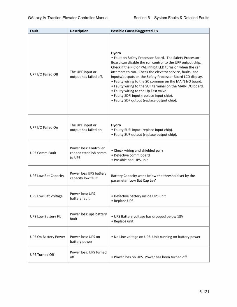
GALaxy IV Traction Elevator Controller Manual Section 6 – System Faults & Detailed Faults
6-121
Fault Description Possible Cause/Suggested Fix
UPF I/O Failed Off The UPF input or output has failed off.
Hydro • Fault on Safety Processor Board. The Safety Processor Board can disable the run control to the UPF output chip. Check if the PIC or PAL inhibit LED turns on when the car attempts to run. Check the elevator service, faults, and inputs/outputs on the Safety Processor Board LCD display. • Faulty wiring to the SC common on the MAIN I/O board. • Faulty wiring to the SUF terminal on the MAIN I/O board. • Faulty wiring to the Up Fast valve • Faulty SDFi input (replace input chip). • Faulty SDF output (replace output chip).
UPF I/O Failed On The UPF input or output has failed on.
Hydro • Faulty SUFi input (replace input chip). • Faulty SUF output (replace output chip).
UPS Comm Fault Power loss: Controller cannot establish comm to UPS
• Check wiring and shielded pairs • Defective comm board • Possible bad UPS unit
UPS Low Bat Capacity Power loss UPS battery capacity low fault
Battery Capacity went below the threshold set by the parameter 'Low Bat Cap Lev'
UPS Low Bat Voltage Power loss: UPS battery fault
• Defective battery inside UPS unit • Replace UPS
UPS Low Battery Flt Power loss: ups battery fault
• UPS Battery voltage has dropped below 18V • Replace unit
UPS On Battery Power Power loss: UPS on battery power
• No Line voltage on UPS. Unit running on battery power
UPS Turned Off Power loss: UPS turned off
• Power loss on UPS. Power has been turned off

GALaxy IV Traction Elevator Controller Manual Section 6 – System Faults & Detailed Faults
6-122
Fault Description Possible Cause/Suggested Fix
User Variable Init User variable initialization
User related parameters such a password and telephone numbers are being initialized. This error occurs on the first time the GALX-1100 CPU board is being powered up.
UT count Fault
The verification position count for the UT input switch was off by more than 10 inches when the switch was activated.
• The car was lost due to a preset error. Check the guides on the selector. Check the fault log for binary preset errors. • The controller has a faulty encoder signal for the pulse count. Check that the car can make long runs without overshooting the floor or stopping short of the floor. • The power common to the limit switches was lost. Check fuse F1 on the selector board. • Incorrect counting of pulse counts. For Tapeless, check encoder connection to motor and encoder wiring. For Tape, check pulse sensors for proper quadrature at selector. • Hoistway not learned properly. Perform a hoistway learn procedure. • UT magnet not adjusted properly. Check at slow speed if sensor input is breaking, making and then breaking again. Magnet needs to be closer to the sensor on the selector.
UT Failed On Fault
UT input Failed On Fault. The car was at the top floor and the UTS input was low true (UTS switch made) but the UT input was high (UT not made).
• The UTS limit is not installed. The UTS limit is used on all controllers as a verification that the car at the top most landing. Add the UTS limit. • The UT did not break at the top terminal landing. Adjust or replace the UT switch. • Faulty UT input. Replace selector board. • Faulty UT sensor on selector sensor board. For Tape replace the sensor board, or For Tapeless replace the individual UT sensor.

GALaxy IV Traction Elevator Controller Manual Section 6 – System Faults & Detailed Faults
6-123
Fault Description Possible Cause/Suggested Fix
UT Limit Vel Fault
NTS Processor detected a car speed at the UT terminal limit that was greater that the clamp (parameter) speed
• Verify that the limit activates at the correct location in the hoistway. • Verify the speed that the car hits the limit and adjust the limit velocity if necessary. • If the acceleration or deceleration rates were changed after the limit velocities were learned, the learn process may need to be repeated or the limit may need to be moved. See: NTS UT Limit Vel Flt
UT Pulse Fault
Selector pulsed the UT latch multiple times but the UT state was not latched
• Memory of the UT sensor is stored on a state saver latch device. Replace the Selector Board. See: SEL UT Pulse Fault
UT Speed Fault
Car hit the UT Limit at a speed greater than the speed limit setting parameter.
• Error previously set from the Safety Processor that is no long used. (See UT Limit Vel Fault).
UT1 count Fault
The verification position count for the UT1 input switch was off by more than 10 inches when the switch was activated.
• The car was lost due to a preset error. Check the guides on the selector. Check the fault log for binary preset errors. • The controller has a faulty encoder signal for the pulse count. Check that the car can make long runs without overshooting the floor or stopping short of the floor. • The power common to the limit switches was lost. Check fuse F1 on the selector board. • Incorrect counting of pulse counts. For Tapeless, check encoder connection to motor and encoder wiring. For Tape, check pulse sensors for proper quadrature at selector. • Hoistway not learned properly. Perform a hoistway learn procedure. • UT1 magnet not adjusted properly. Check at slow speed if sensor input is breaking, making and then breaking again. Magnet needs to be closer to the sensor on the selector.

GALaxy IV Traction Elevator Controller Manual Section 6 – System Faults & Detailed Faults
6-124
Fault Description Possible Cause/Suggested Fix
UT1 Limit Vel Fault
NTS Processor detected a car speed at the UT1 terminal limit that was greater that the clamp (parameter) speed
• Verify that the limit activates at the correct location in the hoistway. • Verify the speed that the car hits the limit and adjust the limit velocity if necessary. • If the acceleration or deceleration rates were changed after the limit velocities were learned, the learn process may need to be repeated or the limit may need to be moved. See: NTS UT1 Limit Vel Flt
UT2 count Fault
The verification position count for the UT2 input switch was off by more than 14 inches when the switch was activated.
• The car was lost due to a preset error. Check the guides on the selector. Check the fault log for binary preset errors. • The controller has a faulty encoder signal for the pulse count. Check that the car can make long runs without overshooting the floor or stopping short of the floor. • The power common to the limit switches was lost. Check fuse F1 on the selector board. • Incorrect counting of pulse counts. For Tapeless, check encoder connection to motor and encoder wiring. For Tape, check pulse sensors for proper quadrature at selector. • Hoistway not learned properly. Perform a hoistway learn procedure. • UT2 magnet not adjusted properly. Check at slow speed if sensor input is breaking, making and then breaking again. Magnet needs to be closer to the sensor on the selector.
UT2 Limit Vel Fault
NTS Processor detected a car speed at the UT2 terminal limit that was greater that the clamp (parameter) speed
• Verify that the limit activates at the correct location in the hoistway. • Verify the speed that the car hits the limit and adjust the limit velocity if necessary. • If the acceleration or deceleration rates were changed after the limit velocities were learned, the learn process may need to be repeated or the limit may need to be moved. See: NTS UT2 Limit Vel Flt

GALaxy IV Traction Elevator Controller Manual Section 6 – System Faults & Detailed Faults
6-125
Fault Description Possible Cause/Suggested Fix
UT3 count Fault
The verification position count for the UT3 input switch was off by more than 18 inches when the switch was activated.
• The car was lost due to a preset error. Check the guides on the selector. Check the fault log for binary preset errors. • The controller has a faulty encoder signal for the pulse count. Check that the car can make long runs without overshooting the floor or stopping short of the floor. • The power common to the limit switches was lost. Check fuse F1 on the selector board. • Incorrect counting of pulse counts. For Tapeless, check encoder connection to motor and encoder wiring. For Tape, check pulse sensors for proper quadrature at selector. • Hoistway not learned properly. Perform a hoistway learn procedure. • UT3 magnet not adjusted properly. Check at slow speed if sensor input is breaking, making and then breaking again. Magnet needs to be closer to the sensor on the selector.
UT3 Limit Vel Fault
NTS Processor detected a car speed at the UT3 terminal limit that was greater that the clamp (parameter) speed
• Verify that the limit activates at the correct location in the hoistway. • Verify the speed that the car hits the limit and adjust the limit velocity if necessary. • If the acceleration or deceleration rates were changed after the limit velocities were learned, the learn process may need to be repeated or the limit may need to be moved. See: NTS UT3 Limit Vel Flt

GALaxy IV Traction Elevator Controller Manual Section 6 – System Faults & Detailed Faults
6-126
Fault Description Possible Cause/Suggested Fix
UT4 count Fault
The verification position count for the UT4 input switch was off by more than 24 inches when the switch was activated.
• The car was lost due to a preset error. Check the guides on the selector. Check the fault log for binary preset errors. • The controller has a faulty encoder signal for the pulse count. Check that the car can make long runs without overshooting the floor or stopping short of the floor. • The power common to the limit switches was lost. Check fuse F1 on the selector board. • Incorrect counting of pulse counts. For Tapeless, check encoder connection to motor and encoder wiring. For Tape, check pulse sensors for proper quadrature at selector. • Hoistway not learned properly. Perform a hoistway learn procedure. • UT4 magnet not adjusted properly. Check at slow speed if sensor input is breaking, making and then breaking again. Magnet needs to be closer to the sensor on the selector.
UT4 Limit Vel Fault
NTS Processor detected a car speed at the UT4 terminal limit that was greater that the clamp (parameter) speed
• Verify that the limit activates at the correct location in the hoistway. • Verify the speed that the car hits the limit and adjust the limit velocity if necessary. • If the acceleration or deceleration rates were changed after the limit velocities were learned, the learn process may need to be repeated or the limit may need to be moved. See: NTS UT4 Limit Vel Flt

GALaxy IV Traction Elevator Controller Manual Section 6 – System Faults & Detailed Faults
6-127
Fault Description Possible Cause/Suggested Fix
UT5 count Fault
The verification position count for the UT5 input switch was off by more than 32 inches when the switch was activated.
• The car was lost due to a preset error. Check the guides on the selector. Check the fault log for binary preset errors. • The controller has a faulty encoder signal for the pulse count. Check that the car can make long runs without overshooting the floor or stopping short of the floor. • The power common to the limit switches was lost. Check fuse F1 on the selector board. • Incorrect counting of pulse counts. For Tapeless, check encoder connection to motor and encoder wiring. For Tape, check pulse sensors for proper quadrature at selector. • Hoistway not learned properly. Perform a hoistway learn procedure. • UT5 magnet not adjusted properly. Check at slow speed if sensor input is breaking, making and then breaking again. Magnet needs to be closer to the sensor on the selector.
UT5 Limit Vel Fault
NTS Processor detected a car speed at the UT5 terminal limit that was greater that the clamp (parameter) speed
• Verify that the limit activates at the correct location in the hoistway. • Verify the speed that the car hits the limit and adjust the limit velocity if necessary. • If the acceleration or deceleration rates were changed after the limit velocities were learned, the learn process may need to be repeated or the limit may need to be moved. See: NTS UT5 Limit Vel Flt

GALaxy IV Traction Elevator Controller Manual Section 6 – System Faults & Detailed Faults
6-128
Fault Description Possible Cause/Suggested Fix
UT6 count Fault
The verification position count for the UT6 input switch was off by more than 42 inches when the switch was activated..
• The car was lost due to a preset error. Check the guides on the selector. Check the fault log for binary preset errors. • The controller has a faulty encoder signal for the pulse count. Check that the car can make long runs without overshooting the floor or stopping short of the floor. • The power common to the limit switches was lost. Check fuse F1 on the selector board. • Incorrect counting of pulse counts. For Tapeless, check encoder connection to motor and encoder wiring. For Tape, check pulse sensors for proper quadrature at selector. • Hoistway not learned properly. Perform a hoistway learn procedure. • UT6 magnet not adjusted properly. Check at slow speed if sensor input is breaking, making and then breaking again. Magnet needs to be closer to the sensor on the selector.
UT6 Limit Vel Fault
NTS Processor detected a car speed at the UT6 terminal limit that was greater that the clamp (parameter) speed
• Verify that the limit activates at the correct location in the hoistway. • Verify the speed that the car hits the limit and adjust the limit velocity if necessary. • If the acceleration or deceleration rates were changed after the limit velocities were learned, the learn process may need to be repeated or the limit may need to be moved. See: NTS UT6 Limit Vel Flt
UTM Contact/GTS Flt UTM contact/GTS input pick fault
GTS input did not come on. Gripper is set and GTS did not come on or turned OFF momentarily
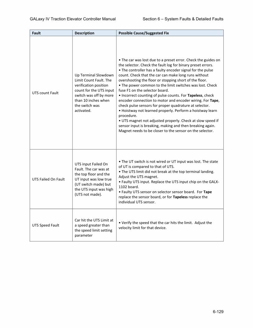
GALaxy IV Traction Elevator Controller Manual Section 6 – System Faults & Detailed Faults
6-129
Fault Description Possible Cause/Suggested Fix
UTS count Fault
Up Terminal Slowdown Limit Count Fault. The verification position count for the UTS input switch was off by more than 10 inches when the switch was activated.
• The car was lost due to a preset error. Check the guides on the selector. Check the fault log for binary preset errors. • The controller has a faulty encoder signal for the pulse count. Check that the car can make long runs without overshooting the floor or stopping short of the floor. • The power common to the limit switches was lost. Check fuse F1 on the selector board. • Incorrect counting of pulse counts. For Tapeless, check encoder connection to motor and encoder wiring. For Tape, check pulse sensors for proper quadrature at selector. • Hoistway not learned properly. Perform a hoistway learn procedure. • UTS magnet not adjusted properly. Check at slow speed if sensor input is breaking, making and then breaking again. Magnet needs to be closer to the sensor on the selector.
UTS Failed On Fault
UTS input Failed On Fault. The car was at the top floor and the UT input was low true (UT switch made) but the UTS input was high (UTS not made).
• The UT switch is not wired or UT input was lost. The state of UT is compared to that of UTS. • The UTS limit did not break at the top terminal landing. Adjust the UTS magnet. • Faulty UTS input. Replace the UTS input chip on the GALX-1102 board. • Faulty UTS sensor on selector sensor board. For Tape replace the sensor board, or for Tapeless replace the individual UTS sensor.
UTS Speed Fault
Car hit the UTS Limit at a speed greater than the speed limit setting parameter
• Verify the speed that the car hits the limit. Adjust the velocity limit for that device.

GALaxy IV Traction Elevator Controller Manual Section 6 – System Faults & Detailed Faults
6-130
Fault Description Possible Cause/Suggested Fix
Velocity Diff Fault
Velocity difference between demand and encoder feedback. This fault sets the rope gripper or emergency brake. Disable this fault by setting Field Variable Vel Diff Dis to 1=Disabled.
• Controller detected a difference between demand and encoder feedback speed greater than the setting under 'Velocity Diff' when the car is decelerating. Make sure speed is tracking properly in acceleration and deceleration. Adjust 'Velocity Diff' based on Speed of the car.
Wrong Dir Pls Run Dn
Wrong Direction Pulses while car running down. The pulse counts should be counting down while the car is running down.
• Check the jumpers on the encoder isolation board. If this car has been previously running properly, the encoder isolation board could be faulty. If during initial setup, change the jumpers for A and A not.
Wrong Dir Pls Run Up
Wrong Direction Pulses while car running up. The pulse counts should be counting up while the car is running up.
• Check the jumpers on the encoder isolation board. If this car has been previously running properly, the encoder isolation board could be faulty. If during initial setup, change the jumpers for A and A not.
XBK Low DC Bus Volts Aux Brake board low dc bus voltage fault
• Incorrect Setting of Line to Line Brake voltage in Adjustable Variables • Incorrect dip-switch setting for Three Phase or Single Phase • Low Line Voltage • Rectifiers blown or have bad connection
XBK No Currnt w/Volt Aux Brake board no current fault with voltage applied
• No brake connected • Bad current sensor • Check if board is low current or high current board.
XBK No DC Bus Volts Aux Brake board no dc bus voltage fault
• No AC Voltage Coming into AC1-AC2-AC3 • Rectifiers blown or have bad connection

GALaxy IV Traction Elevator Controller Manual Section 6 – System Faults & Detailed Faults
6-131
Fault Description Possible Cause/Suggested Fix
XBK No Output Volts Aux Brake board not output voltage fault
• IGBT Not Gating
XBK Over Current Flt Aux Brake board over current fault
• IGBT shorted • Free wheeling diode shorted • Gating circuitry shorted ON
XBK Over Voltage Flt Aux Brake board over voltage fault
• IGBT shorted • Gating circuitry shorted ON
XBK Rq Volt > DC Bus Aux Brake board dmd voltage greater than dc bus voltage fault
• Incorrect Setting of Pick/Hold/Re-level Voltage in Adjustable Variables • Low Line Voltage
Zero Vel Decel Roll
Zero Velocity Deceleration Roll. The controller calculated a velocity value of zero during the roll in to constant deceleration.
• This fault should never occur. Please call the factory if this fault occurs.

GALaxy IV Traction Elevator Controller Manual Section 6 – System Faults & Detailed Faults
6-132
6.2 Detailed Faults Data and Description
Example of data stored in the standard or long term fault log:
517 Inspection Input Flt 2:10:14 2/19/2015 Position = 1 Occurrences = 1
srv=000, prc=002, drf=000, rdf=000, dpr=000, dir=000, emp=000, med=000
cbl=000, equ=000, fir=000, rfi=000, hsf=000, stf=000, cal=000, esp=000
nst=000, rlv=000, ste=001, dfs=000, st0=000, ins=01h, nds=000, dev=00h
pf1=00h, pf2=00h, dv2=00h, io0=a1h, io1=0fh, io2=7eh, io3=20h, io4=c3h
io5=6fh, io6=7ch, io7=8dh, io8=00h, io9=00h, ioA=c7h, ioB=f7h, ioC=ffh
ioD=fbh, ioE=35h, ioF=00h, ioG=00h, ioH=f0h, ioI=0fh, ioJ=f1h, ioK=0fh
ioL=3fh, ioM=30h, ioN=00h, ioO=05h, ioP=07h, ioQ=00h
ioR=00h, ioS=00h, ioT=00h
statusf=00000040h, statusf2=00000000h
DPP Count = 126400, Target = 0, Drv Vel = 0, Enc Vel = 0
Calc Vel = 0, Dmd Vel = 0, Vel Diff = 0, Enc Dir = 0
SPB Poscnt = 0, SPB Vel = 0
SPB Serv = 0h, SPB Cmd = 4h, SPB Stat = 0h
SPB ios1=00h, ios2=00h, ios3=00h, ios4=00h, ios5=00h
Flt Bits 1 = 1h, Flt Bits 2 = 0h, Flt Bits 3 = 1h, Flt Bits 4 = 0h
SS Status=0000h, PWR Status=0000h, Run Status=008013f8h
NTS Vel = 0, NTS Serv = 0h, NTS Cmd = 0h, NTS Stat = 0h
NTS Lim Flt[0] = 0h, NTS Lim Flt[1] = 0h, NTS Lim Flt[2] = 0h
NTS ios1=00h, ios2=00h, ios3=00h
Nudg Flags=00h, Door Req=08h, Call Flags=00h
Chk Run=23h, Chk Start=00h, Chk Level=00h, Chk Door=24h
Front SD=0000h, Rear SD=0000h, Motion Tmr=00001
PAL Vel=00000, PAL Statusf=00h, Inspect Svc=000
Drive Command=0000h, Drive Statusf=0000h
Torque Command=00000, Motor Torque=00000, Percent Load= 4
Example of detailed fault data on LCD Display Interface:
"srv= 0, prc= 2, drf= 0 "
"rdf= 0, dpr= 0, dir= 0 "

GALaxy IV Traction Elevator Controller Manual Section 6 – System Faults & Detailed Faults
6-133
"emp= 0, med= 0, cbl= 0 "
"equ= 0, fir= 0, rfi= 0 "
"hsf= 0, stf= 0, cal= 0 "
"esp= 0, nst= 0, rlv= 0 "
"ste= 1, dsf= 0, st0= 0 "
"ins=01, nds= 0, dev=00 "
"pf1=00, pf2=00, dv2=00 "
"io0=A1, io1=0F, io2=7E "
"io3=20, io4=C3, io5=6F "
"io6=7C, io7=8D, io8=00 "
"io9=00, ioA=C7, ioB=F7 "
"ioC=FF, ioD=FB, ioE=35 "
"ioF=00, ioG=00, ioH=F0 "
"ioI=0F, ioJ=F1, ioK=0F "
"ioL=3F, ioM=30, ioN=00 "
"ioO=05, ioP=07, ioQ=00 "
"ioR=05, ioS=07, ioT=00 "
" statusf = 00000040 "
" statusf2 = 00000000 "
"Dp= 126400, Tg= 0"
"DrvV= 0, EncVel= 0"
"CalcV= 0,DmdVel= 0"
"VDif= 0, Enc Dir = 0 "
"SPB Cnt = 0 "
"SPB Vel= 0, Stat=00 "
"SPB Srv=00,Cmd=04,S1=00 "
"S2=00,S3=00,S4=00,S5=00 "
"FltB1=01 FltB2=00 "
"FltB3=01 FltB4=00 "
"SsStat=0000,PwrStat=0000"
"Run Status = 008013f8 "
"NTS Vel= 0, Stat=00 "

GALaxy IV Traction Elevator Controller Manual Section 6 – System Faults & Detailed Faults
6-134
"NTS Serv=00, Cmd=00 "
"LmF1=00 LmF2=00 LmF3=00 "
"Nio1=00 Nio2=00 Nio3=00 "
"Nud=00, DRq=08, CFg=00 "
"RnS=23, StS=00, LvS=00 "
"DrS=24,FSd=0000,RSd=0000"
"Motion Tmr = 1 "
"PAL Vel=00000, Stat= "
"Ins Svc=00, % Load = 4"
"DrvCmd=0000,TrqCmd= 0"
"DvStat=0000,MtrTrq= 0"
SRV: SRV Service Flag
0 = Out of Service
1 = Automatic
2 = Independent
3 = Load Weighing Bypass
4 = Attendant
5 = Code Blue
6 = Fire Phase 2
7 = Emergency Power
8 = Earthquake Emergency
9 = Fire Phase 1 Main Egress
10 = Fire Phase 1 Alternate Egress
11 = Homing
12 = Reset Run Up
13 = Reset Run Down
14 = Low Oil Operation
15 = Return to Lobby
16 = Load Overload
17 = Massachusetts Medical Emergency
18 = Calibrate load weigher
19 = CS Elevator Off
20 = HS Elevator Off
21 = Low Pressure Operation
22 = Hospital Service Operation
23 = VIP Service Operation
24 = Security Recall
25 = Sabbath service
26 = TUG Service operation
27= Hot Oil Operation
28= Riot Control

GALaxy IV Traction Elevator Controller Manual Section 6 – System Faults & Detailed Faults
6-135
PRC: Process Flag
1 = Reset
2 = Inspection
3 = Motion:
hsf=1, dir=1, Up Fast
hsf=0, dir=1, ul=0, Up Transition
hsf=0, dir=1, ul=1, Up Leveling
hsf=1, dir=2, Down Fast
hsf=0, dir=2, dl=0, Down Transition
hsf=0, dir=2, dl=1, Down Leveling
4 = Motion Mode 1 – Soft Start
5 = Motion Mode 2 – Constant Acceleration
6 = Motion Mode 3 – Roll Over to Max Velocity
7 = Motion Mode 4 – Constant Velocity
8 = Motion Mode 5 – Roll Over to Deceleration
9 = Motion Mode 6 – Constant Deceleration
10 = Motion Mode 7 – Targeting Floor
11 = Motion Mode 8 – Emergency Slowdown
12 = Safety String
13 = Turned Off
14 = Parked
15 = Waiting Assignment
16 = Doors Operation
17 = Elevator Stalled (or Low Oil for Hydro)
18 = Elevator Resetting Hydro Jack
19 = Elevator on Low Oil Pressure mode
20 = Elevator is in Automatic Learn Hoistway
21 = Elevator is in Emergency Power Recovery
22= Hot Oil Mode
DRF: Front Door Flag RDF: Rear Door Flag
0 = Door Closed
1 = Door Opening
2 = Door Dwelling
3 = Door Closing
4 = Door Nudging Closed
0 = Door Closed
1 = Door Opening
2 = Door Dwelling
3 = Door Closing
4 = Door Nudging Closed
DPR: Direction Preference Flag DIR: Car Direction Flag
0 = None
1 = Up
2 = Down
0 = None
1 = Up
2 = Down

GALaxy IV Traction Elevator Controller Manual Section 6 – System Faults & Detailed Faults
6-136
EMP: Emergency Power Flag
0 = Not on Emergency Power
1 = On Emergency Power Waiting
2 = On Emergency Power Waiting with Doors Open
3 = On Emergency Power Returning Home
4 = On Em. Power Returned Home with Doors Open
5 = On Em. Power Returned Home with Doors Closed
6 = On Emergency Power and Selected to Run
7 = On Emergency Power waiting with Doors Closed
MED: Medical Emergency
0 = No Medical Emergency Service
1 = Recall Car to Medical Emergency Recall Floor
2 = At Return Floor with Door Open (Return Complete)
4 = On EMS Car Call Service
5 = On EMS Car Hold Service (key off but not at the recall floor)

GALaxy IV Traction Elevator Controller Manual Section 6 – System Faults & Detailed Faults
6-137
CBL: Code Blue Flag
0 = No Code Blue
1 = Recall to Emergency Floor
2 = At Code Blue Floor
3 = At Code Blue Floor with Door Open
4 = Finished Code Blue
EQU: Earthquake Flag
0 = Not on Earthquake Operation
1 = Earthquake Sensor Activated
2 = Counterweight Derailment Sensor Activated
3 = Recover Away From the Counterweight
4 = Stopped at a Floor
FIR: Fire Flag
0 = Not on Fire Service
1 = Phase 1 Main Egress Return
2 = Phase 1 Alternate Egress Return
3 = Phase 1 Completed
4 = Phase 2 Door Hold
5 = Phase 2 Constant Pressure Door Open
6 = Phase 2 Constant Pressure Door Close
7 = Phase 2 Door Hold
8 = Phase 2 Momentary DCB Door Close
RFI: Rear Fire Flag
0 = Not on Fire Service
1 = Phase 1 Main Rear Egress Return
2 = Phase 1 Alternate Rear Egress Return
3 = Phase 1 Completed
4 = Phase 2 Rear Door Hold
5 = Phase 2 Constant Pressure Rear Door Open
6 = Phase 2 Constant Pressure Rear Door Close
7 = Phase 2 Rear Door Hold
8 = Phase 2 Momentary DCB Rear Door Close

GALaxy IV Traction Elevator Controller Manual Section 6 – System Faults & Detailed Faults
6-138
ESP: Emergency Stop Flag NST: Need to Stop Flag
1 = Emergency Stop 1 = Car need to stop at next floor
RLV: Re-level Flag STE: Step Flag
1 = Car in re-leveling 1 = Step to the next position (non-distance feedback)
HSF: High Speed Flag STF: Start Flag
0 = No High Speed
1 = High Speed
0 = Not valid Start
1 = Start of Run
CAL: Direction of Calls
0 = No Call
1 = Above Call
2 = Below Call
3 = Above and Below Calls
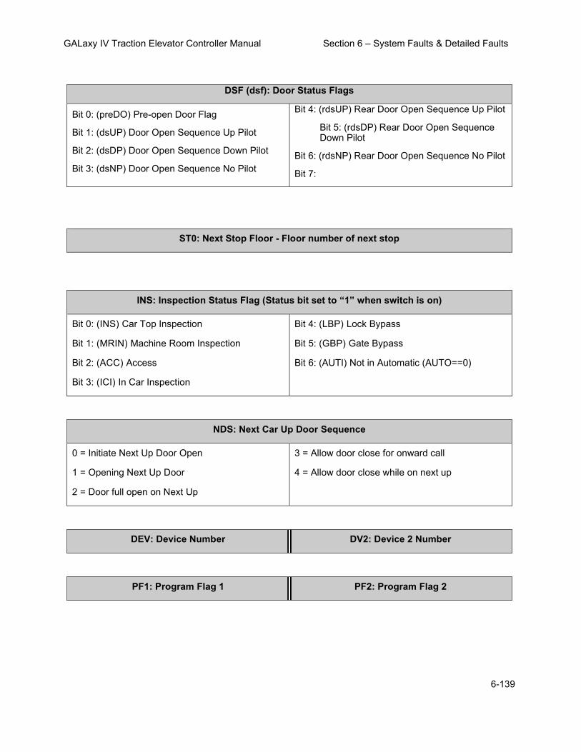
GALaxy IV Traction Elevator Controller Manual Section 6 – System Faults & Detailed Faults
6-139
DSF (dsf): Door Status Flags
Bit 0: (preDO) Pre-open Door Flag
Bit 1: (dsUP) Door Open Sequence Up Pilot
Bit 2: (dsDP) Door Open Sequence Down Pilot
Bit 3: (dsNP) Door Open Sequence No Pilot
Bit 4: (rdsUP) Rear Door Open Sequence Up Pilot
Bit 5: (rdsDP) Rear Door Open Sequence Down Pilot
Bit 6: (rdsNP) Rear Door Open Sequence No Pilot
Bit 7:
ST0: Next Stop Floor - Floor number of next stop
INS: Inspection Status Flag (Status bit set to “1” when switch is on)
Bit 0: (INS) Car Top Inspection
Bit 1: (MRIN) Machine Room Inspection
Bit 2: (ACC) Access
Bit 3: (ICI) In Car Inspection
Bit 4: (LBP) Lock Bypass
Bit 5: (GBP) Gate Bypass
Bit 6: (AUTI) Not in Automatic (AUTO==0)
NDS: Next Car Up Door Sequence
0 = Initiate Next Up Door Open
1 = Opening Next Up Door
2 = Door full open on Next Up
3 = Allow door close for onward call
4 = Allow door close while on next up
DEV: Device Number DV2: Device 2 Number
PF1: Program Flag 1 PF2: Program Flag 2

GALaxy IV Traction Elevator Controller Manual Section 6 – System Faults & Detailed Faults
6-140
STATUSF: Control Status Flag (Status bit set to “1” when status active)
Bit 0: (sfS10) NO S10 power
Bit 1: (sfHC) NO HC power
Bit 2: (sfSS) NO SS input
Bit 3: (sfRDY) Drive not ready
Bit 4: (sfGRP) Gripper/EBK error
Bit 5: (sfIO) I/O error during redundancy check
Bit 6: (sfINS) Inspection or lock bypass fault
Bit 7: (sfBPI) Binary Position Input Error
Bit 8: (sfPOS) Position Error
Bit 9: (sfAD) No automatic Doors
Bit 10: (sfSTP) Stop switch open
Bit 11: (sfDZ) Door Zone fault
Bit 12: (sfGDL) Gate or Door lock fault
Bit 13: (sfP) No Potential “P” Input
Bit 14: (sfDCL)No DCL
Bit 15: (sfDCC) No Door Close Contact
Bit 16: (sfBKS) Brake lift switch error
Bit 17: (sfTOC) Top of Car Communications Error
Bit 18: (sfDRV) Drive Communications Error
Bit 19: (sfSPB) Safety Processor Board Communications Error
Bit 20: (sfDBR) DB Resistor Temp. Error
Bit 21: (sfSHD) Shutdown (too many run attempts with faults)
Bit 22: (sfAST) Annual Safety Test
Bit 23: (sfSAF) Waiting for Safe (Door Locks and Gate)
Bit 24: (sfTLM) UT,UTS,DT or DTS limit error
Bit 25: (sfGTS) GTS input off
Bit 26: (sfDZF) UL, DL and DZ off at floor
Bit 27: (sfBKC) Brake Board Can Error
Bit 28: (sfFST) Fire Fighter Stop Switch
Bit 29: (sfSEL) Selector Can error
Bit 30: (sfUDL) UL or DL fault
Bit 31: (sfLEV) Leveling fault

GALaxy IV Traction Elevator Controller Manual Section 6 – System Faults & Detailed Faults
6-141
STATUSF2: Control Status Flag (Status bit set to “1” when status active)
Bit 0: (sfHWI) Hardware Init fault
Bit 1: (sfFDC) Front Door Closing Fault
Bit 2: (sfRDC) Rear Door Closing Fault
Bit 3: (sfLVF) Line Voltage Fault
Bit 4: (sfDVF) Door Voltage Fault
Bit 5: (sfBKR) Brake lift switch run error
Bit 6: (sfDMO) Door motor overload
Bit 7: (sfHWL) Learn Hoistway Fault
Bit 8: (sfHWL) Power Loss UPS Fault
Bit 9: (sfEBK) Emergency Brake Can error
Bit 10: (sfKEB) KEB Drive Not in Run Mode
Bit 11: (sfAFS) At Floor Shutdown
Bit 12: (s1036) 1036 board connected
Bit 13: (sfRSR) Reset run fault
Bit 14: (sfSCT) Invalid SEL count
Bit 15: (sfCOP) COP can comm error
Bit 16: (sfECN) Encoder can comm error
Bit 17: (sfIOT) IO Test in progress
Bit 18: (sfGRT) Gripper Test in progress
Bit 19: (sfDVP) No Power to Drive
Bit 20: (sfNIT) Non Interference timer
Bit 21: (sfDRQ) Door open request
Bit 22: (sfDPM) Waiting for DPM
Bit 23: (sfRPM) Waiting for RPM
Bit 24: (sfVSC) Viscosity operation
Bit 25: (sfLVR) Leveling request
Bit 26: (sfTSP) Terminal Limit Speed Clamp
Bit 27: (sfSPR) Sped Rate Clamp
Bit 28: (sfEES) Front EE Test failed fault
Bit 29: (sfERS) Rear EE Test failed fault
Bit 30:
Bit 31:
DPP Count (DP): Position counts in pulses Target (TG) = Target Count in pulses
Drv Vel (DrvV): Velocity sent to the Drive in fpm (From Dmd Vel and rate limited) Enc Vel : Velocity feedback from Encoder in fpm
Calc Vel (CalcV): Speed profile calculated velocity in fpm
Dmd Vel: Demand Velocity ( From Calc Vel and speed clamp limited)
Vel Diff (VDif): Velocity Difference (Drv Vel – Enc Vel) in fpm
Enc Dir: Encoder Direction 0=none, 1=up, 2=down
SPB Cnt: Safety Processor Position Count SPB Vel: Safety Processor Velocity in fpm

GALaxy IV Traction Elevator Controller Manual Section 6 – System Faults & Detailed Faults
6-142
SPB Serv: Safety Processor Board Service:
0: Automatic
1: Car Top Inspection
2: Gate Bypass operation
3: Lock Bypass Operation
4: Access
5: Motor Room Inspection
6: In Car Inspection
7: Inspection Error
8: Gate or Lock Bypass Err
9: Velocity Error
10: UP Error on pwrup
11: DNR Error on pwrup
12: Both UNI and DNI inputs
13: EEprom Error
14: No UTS Error
15: No DTS Error
16: Pulse Error
17: Unintended Motion Error

GALaxy IV Traction Elevator Controller Manual Section 6 – System Faults & Detailed Faults
6-143
SPB Cmd: Safety Processor Command. (Controller command to safety processor)
Bit 0: 1 = Initialize Position
Bit 1: 1 = Immediate update
Bit 0: (ntsTV ) 1 = NTS Test (verification)
Bit 1: (etsTV ) 1 = ETS Test (verification)
Bit 2: (rUMOT ) 1 = Reset Unintended motion fault
Bit 3: (sUMOT) 1 = Set Unintended motion fault
Bit 4: (gr1T ) 1 = GR1 test
Bit 5: (sfcT ) 1 = SFC test
Bit 6: (gr1PK ) 1 = GR1 pick command
Bit 7: (sMENU ) 1 = Force Car Speed Menu
Bit 8: (brkTG ) 1 = Trigger Brake
Bit 9: (ebkTG) 1 = Trigger Emergency Brake
Bit10: (bkLV ) 0 = Brk Line Voltage, 1 = Em Brk Line Voltage
Bit11: (rCAN2) 1 = Reset can2 comm status
Bit12: (ntsT ) 1 = NTS Test
Bit13: (etsT ) 1 = ETS Test
Bit14: (adDIS ) 1 = Automatic Door disabled
Bit15: (sUMTV ) 1 = Set Unintended motion fault (verification)
SPB Stat: Safety Processor Status
Bit 0: (SFC ) Secondary Fault Control (1=fault)
Bit 1: (FLT) Pic Fault (SPB CPU 1=fault)
Bit 2: (GRF) Gripper Fault (1=fault)
Bit 3: (COM) Comm Fault (1=fault)
Bit 4: (VEL) Velocity Fault (1=fault)
Bit 5: (PCI) Position Count Initialized (1=initialized)
Bit 6: (ACT) Active Fault (1=fault)
Bit 7: (PCU) Position Count Updated (1=updated)
SPB ios1: (S1) Safety Processor I/O Byte 1 SPB ios2: (S2) Safety Processor I/O Byte 2
Bit 0: DLM
Bit 1: DL
Bit 2: AUTO
Bit 3: GBP
Bit 4: LBP
Bit 5: MRI
Bit 6: UL
Bit 7: INS
Bit 0: ICI
Bit 1: ACC
Bit 2: UTS
Bit 3: DTS
Bit 4: RGS
Bit 5: RLM
Bit 6: DLB
Bit 7: DZO
SPB ios3: (S3) Safety Processor I/O Byte 3 SPB ios4: (S4) Safety Processor I/O Byte 4
Bit 0: unused
Bit 1: unused
Bit 2: ETS
Bit 3: UP
Bit 4: DNR
Bit 5: GS
Bit 6: DLT
Bit 7: unused
Bit 0: SFCO
Bit 1: PICEN
Bit 2: LSC
Bit 3: comFLT
Bit 4: velFLT
Bit 5: posINIT
Bit 6: actFLT
Bit 7: posUPD

GALaxy IV Traction Elevator Controller Manual Section 6 – System Faults & Detailed Faults
6-144
SPB ios5: (S5) Safety Processor I/O Byte 5
Bit 0: GR1
Bit 1: unused
Bit 2: unused
Bit 3: unused
Bit 4: unused
Bit 5: unused
Bit 6: Up Velocity Direction
Bit 7: Down Velocity Direction
Flt Bits 1 (FltB1): Faults Bits 1 (Byte 0)
Bit 0: (fHWLN) Hoistway Not Learned (1=fault)
Bit 1: (fHWI) Hardware Init Fault (1=fault)
Bit 2: (fLIMD) Limit Direction Fault
Bit 3: (fSPBD) Safety Processor Direction Fault
Bit 4: (fVELD) Velocity Decel Difference Fault
Bit 5: (fSPVD) Safety Processor Velocity Difference Fault
Bit 6: (fUDLD) UL DL Direction Fault
Bit 7: (fLEV) Leveling Fault
Flt Bits 2 (FltB2): Fault Bits 2 (Byte 1)
Bit 0: (fCOPC) COP CAN COM error
Bit 1: (fSPBC) Safety Processor CAN COM error
Bit 2: (fB1B2) unused
Bit 3: (fB1B3) unused
Bit 4: (fSLCT) Selector Count Valid
Bit 5: (fSELC) Selector CAN COM error
Bit 6: (fENCC) CAN Encoder COM error
Bit 7: (fENCI) CAN Encoder Init

GALaxy IV Traction Elevator Controller Manual Section 6 – System Faults & Detailed Faults
6-145
Flt Bits 3 (FltB3): Fault Bits 3 (Byte 2)
Bit 0: (fDVOF) Drive com off line (1=off line)
Bit 1: (fDBRT) DBR Temperature Fault
Bit 2: (fMTOL) Door Motor Overload
Bit 3: (FB2B3) unused
Bit 4: (fB2B4) unused
Bit 5: (fB2B5) unused
Bit 6: (fB2B6) unused
Bit 7: (fB2B7) unused
Flt Bits 4 (FltB4): Fault Bits 4 (Byte 3)
Bit 0: (fGRIP) Gripper/EMBK Fault
Bit 1: (fENCD) Encoder Direction Fault
Bit 2: (fB3B2) unused
Bit 3: (fB3B3) unused
Bit 4: (fB3B4) unused
Bit 5: (fB3B5) unused
Bit 6: (fB3B6) unused
Bit 7: (fB3B7) unused
SS Status: Safety String Status
Bit 0: (ssGOV) Governor input open
Bit 1: (ssTF)Top Final Limit Open
Bit 2: (ssBF) Bottom Final Limit open
Bit 3: (ssPS) Pit Switch open
Bit 4: (ssHSS) Hoistway Safety
Bit 5: (ssCTS) Car Top Stop switch open
Bit 6: (ssCSS) Car Safety Switch open
Bit 7: (ssRLS) Rail Lock Switch
Bit 8: (ssFFS) Fire Fighter Stop Switch
Bit 9: (ssCST) Car Stop Switch
Bit 10: (ssMRS) Machine Room Stop Switch
Bit 11: (ssGTS) Gripper Trip Switch
Bit 12:
Bit 13:
Bit 14:
Bit 15:
PWR Status: Power Status
Bit 0: (psHC) Hall call power loss
Bit 1: (psHCL) Hall call light power loss
Bit 2: (psCC) Car call power loss
Bit 3: (psCCL) Car call light power loss
Bit 4: (psLHC) Lobby Hall common power loss
Bit 5: (psFEP) Fire/Emergency Power Loss
Bit 6:
Bit 7:
Bit 8:
Bit 9:
Bit 10:
Bit 11:
Bit 12:
Bit 13:
Bit 14:
Bit 15:

GALaxy IV Traction Elevator Controller Manual Section 6 – System Faults & Detailed Faults
6-146
Run Status: Control Run Status Flag (Status bit set to “1” when status active)
Bit 0: (rsRUN) Car is running
Bit 1: (rsDNR) Down run signal
Bit 2: (rsUP) Up run signal
Bit 3: (rsDL) Down Door Zone Limit
Bit 4: (rsUL) Up Door Zone limit
Bit 5: (rsDZ) Door Zone
Bit 6: (rsDLT) Door Lock Top
Bit 7: (rsDLM) Door Lock Middle
Bit 8: (rsDLB) Door Lock bottom
Bit 9: (rsGS) Gate Switch
Bit 10: (rsRLM) Rear Door Lock Middle
Bit 11: (rsRGS) Rear Gate Switch
Bit 12: (rsDOL) Door open limit (0=active)
Bit 13: (rsDCL) Door Close Limit (0=active)
Bit 14: (rDOLR) Rear door open limit (0=active)
Bit 15: (rDCLR) Rear door close limit (0=active)
Bit 16: (rsEE) Electric eye or Detector Edge
Bit 17: (rsSE) Safety Edge
Bit 18: (rsEER) Rear Electric eye or Detector edge
Bit 19: (rsSER) Rear Safety Edge
Bit 20: (rsHSF) High Speed Flag
Bit 21: (rsSTF) Start Flag
Bit 22: (rLSTF) Leveling Start Flag
Bit 23: (rsDZA) Door Zone OR'd
Bit 24: (rsDO) Door Open
Bit 25: (rsDC) Door Close
Bit 26: (rsDOR) Rear Door Open
Bit 27: (rsDCR) Rear Door Close
Bit 28:
Bit 29:
Bit 30:
Bit 31:

GALaxy IV Traction Elevator Controller Manual Section 6 – System Faults & Detailed Faults
6-147
NTS Vel: NTS Processor Velocity
NTS Stat: NTS Processor Status
Bit 0: Direction up,
Bit 1: Direction down
Bit 2: SEL comm okay
Bit 3: SPB comm okay
Bit 4: Velocity direction (should match up or down)
Bit 5: Direction fault
Bit 6: Limit (EMSD) fault
Bit 7: Velocity fault
NTS Serv: NTS Processor Service
1 = normal
2 = EM Slowdown
3 = UN Limit Stop
4 = DN Limit Stop
NTS Cmd: NTS Processor Command
Bit 0: 1 = (EMSD) Emergency Slowdown
Bit 1: 1 = (NTST) NTS Test
Bit 2: 1 = (ETST) ETS Test
Bit 3: 1 = (ADD) Automatic Door disabled
LimFlt0: Limit Fault Byte 0 LimFlt1: Limit Fault Byte 1
Bit0: unF
Bit1:
Bit2: utF
Bit3:
Bit4: utsF
Bit5: ut1F
Bit6: ut2F
Bit7: ut3F
Bit0: ut4F
Bit1: ut5F
Bit2: ut6F
Bit3
Bit4: dnF
Bit5:
Bit6: dtF
Bit7:
LimFlt2: Limit Fault Byte 2 NTSIO1: NTS Processor I/O Byte 1
Bit0: dtsF
Bit1: dt1F
Bit2: dt2F
Bit3: dt3F
Bit4: dt4F
Bit5: dt5F
Bit6: dt6F
Bit7:
Bit 0: UN
Bit 1: UT
Bit 2: UT1
Bit 3: UT2
Bit 4: UT3
Bit 5: UT4
Bit 6: UT5
Bit 7: UT6
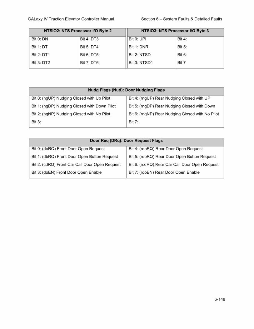
GALaxy IV Traction Elevator Controller Manual Section 6 – System Faults & Detailed Faults
6-148
NTSIO2: NTS Processor I/O Byte 2 NTSIO3: NTS Processor I/O Byte 3
Bit 0: DN
Bit 1: DT
Bit 2: DT1
Bit 3: DT2
Bit 4: DT3
Bit 5: DT4
Bit 6: DT5
Bit 7: DT6
Bit 0: UPI
Bit 1: DNRI
Bit 2: NTSD
Bit 3: NTSD1
Bit 4:
Bit 5:
Bit 6:
Bit 7
Nudg Flags (Nud): Door Nudging Flags
Bit 0: (ngUP) Nudging Closed with Up Pilot
Bit 1: (ngDP) Nudging Closed with Down Pilot
Bit 2: (ngNP) Nudging Closed with No Pilot
Bit 3:
Bit 4: (rngUP) Rear Nudging Closed with UP
Bit 5: (rngDP) Rear Nudging Closed with Down
Bit 6: (rngNP) Rear Nudging Closed with No Pilot
Bit 7:
Door Req (DRq): Door Request Flags
Bit 0: (doRQ) Front Door Open Request
Bit 1: (dbRQ) Front Door Open Button Request
Bit 2: (cdRQ) Front Car Call Door Open Request
Bit 3: (doEN) Front Door Open Enable
Bit 4: (rdoRQ) Rear Door Open Request
Bit 5: (rdbRQ) Rear Door Open Button Request
Bit 6: (rcdRQ) Rear Car Call Door Open Request
Bit 7: (rdoEN) Rear Door Open Enable
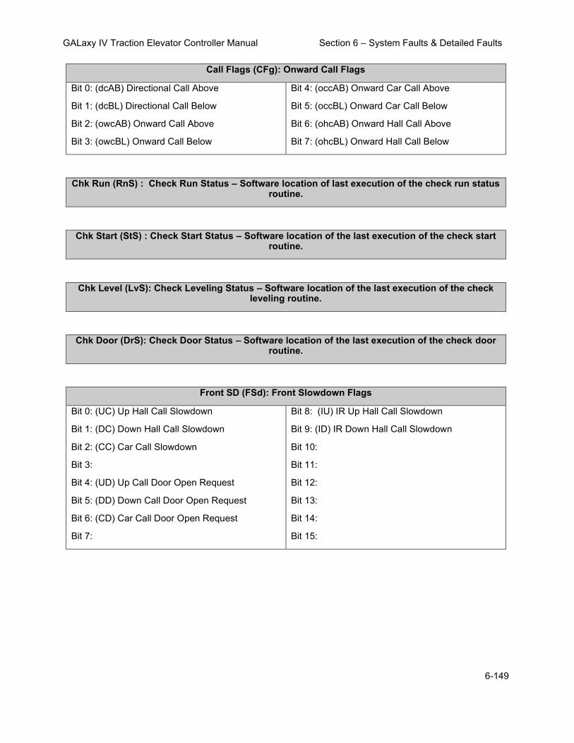
GALaxy IV Traction Elevator Controller Manual Section 6 – System Faults & Detailed Faults
6-149
Call Flags (CFg): Onward Call Flags
Bit 0: (dcAB) Directional Call Above
Bit 1: (dcBL) Directional Call Below
Bit 2: (owcAB) Onward Call Above
Bit 3: (owcBL) Onward Call Below
Bit 4: (occAB) Onward Car Call Above
Bit 5: (occBL) Onward Car Call Below
Bit 6: (ohcAB) Onward Hall Call Above
Bit 7: (ohcBL) Onward Hall Call Below
Chk Run (RnS) : Check Run Status – Software location of last execution of the check run status routine.
Chk Start (StS) : Check Start Status – Software location of the last execution of the check start routine.
Chk Level (LvS): Check Leveling Status – Software location of the last execution of the check leveling routine.
Chk Door (DrS): Check Door Status – Software location of the last execution of the check door routine.
Front SD (FSd): Front Slowdown Flags
Bit 0: (UC) Up Hall Call Slowdown
Bit 1: (DC) Down Hall Call Slowdown
Bit 2: (CC) Car Call Slowdown
Bit 3:
Bit 4: (UD) Up Call Door Open Request
Bit 5: (DD) Down Call Door Open Request
Bit 6: (CD) Car Call Door Open Request
Bit 7:
Bit 8: (IU) IR Up Hall Call Slowdown
Bit 9: (ID) IR Down Hall Call Slowdown
Bit 10:
Bit 11:
Bit 12:
Bit 13:
Bit 14:
Bit 15:

GALaxy IV Traction Elevator Controller Manual Section 6 – System Faults & Detailed Faults
6-150
Rear SD (RSd): Rear Slowdown Flags
Bit 0: (UC) Up Hall Call Slowdown
Bit 1: (DC) Down Hall Call Slowdown
Bit 2: (CC) Car Call Slowdown
Bit 3:
Bit 4: (UD) Up Call Door Open Request
Bit 5: (DD) Down Call Door Open Request
Bit 6: (CD) Car Call Door Open Request
Bit 7:
Bit 8: (IU) IR Up Hall Call Slowdown
Bit 9: (ID) IR Down Hall Call Slowdown
Bit 10:
Bit 11:
Bit 12:
Bit 13:
Bit 14:
Bit 15:
Motion Tmr: Motion Timer – Timer while the car is in or attempting motion. 100 msec
PAL Vel: Safety PAL Velocity in fpm
PAL Stat: Safety PAL Status
Bit 0: (PFT) Pulse Fault,
Bit 1: (UTF) ETSU Fault
Bit 2: (DTF) ETSD Fault
Bit 3: (FLT) PAL Fault
Bit 4: (RSB) Reduced Stroke Buffer Enabled
Bit 5: (TST) ESLD Test (Ignore ESLD and/or Write Parameter Enable)
Bit 6: (REN) Rear Door Enable
Bit 7: Encoder Direction (0=normal, 1=invert)
Inspect Svc: Inspection Service
0 = Invalid Inspection Input
1 = Car Top Inspection
2 = Machine Room Inspection
3 = Access Inspection
4 = In-Car Inspection
5 = Car Top Inspection Lock Bypass
6 = Car Top Inspection Gate Bypass
7 = Car Top Inspection Gate and Lock Bypass
% Load:Percent Load Calculated load value from the load weigher

GALaxy IV Traction Elevator Controller Manual Section 6 – System Faults & Detailed Faults
6-151
DrvCmd: Drive Command
Bit 0: (CRL) 1=Control Release
Bit 1: (FLT) 1=Error Occurred
Bit 2: (RUN) 0=stop, 1=run
Bit 3: (REV) 0=forward, 1=reverse
Bit 4:
Bit 5:
Bit 7:
Bit 8:
Bit 9:
Bit 10:
Bit 11:
Bit 12:
Bit 13:
Bit 14:
Bit 15:
DvStat: Drive Status Flag (KEB LED Keypad)
Bit 0: (RUN) Run or Control Release
Bit 1: (RST) Reset Fault
Bit 2: (UP) Run Forward
Bit 3: (DN) Run Reverse
Bit 4:
Bit 5:
Bit 7:
Bit 8:
Bit 9:
Bit 10:
Bit 11:
Bit 12:
Bit 13:
Bit 14:
Bit 15:
DvStat: Drive Status Flag (KEB LCD Keypad) (See Inverter Status GD02 in 6.3.3 at the end of this section or search for GD02 in the KEB Manual)
TrqCmd: Torque Command – Calculated Torque value sent to the drive
MtrTrq: Motro Torque – Actual torque value from the drive

GALaxy IV Traction Elevator Controller Manual Section 6 – System Faults & Detailed Faults
6-152
6.2.1 Detailed Fault I/O Data Example
The data in the I/O block is read from left to right with the left-most bit being the MSB (Most Significant Bit) and the right-most bit being the LSB (Least Significant Bit). Each bit represents the state (on or off) of the corresponding I/O. The table below provides the HEX number and the associated Binary number.
CONVERSION TABLE
HEX BINARY DECIMAL
0 0 0 0 0 0
1 0 0 0 1 1
2 0 0 1 0 2
3 0 0 1 1 3
4 0 1 0 0 4
5 0 1 0 1 5
6 0 1 1 0 6
7 0 1 1 1 7
8 1 0 0 0 8
9 1 0 0 1 9
A 1 0 1 0 10
B 1 0 1 1 11
C 1 1 0 0 12
D 1 1 0 1 13
E 1 1 1 0 14
F 1 1 1 1 15
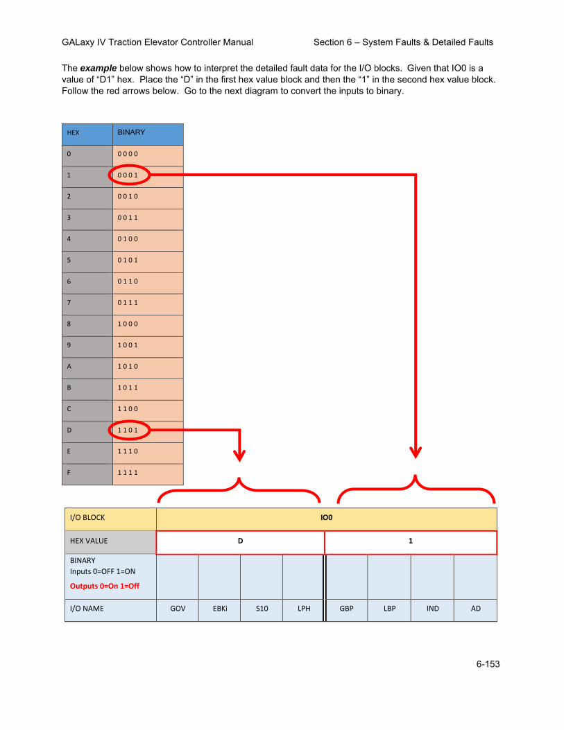
GALaxy IV Traction Elevator Controller Manual Section 6 – System Faults & Detailed Faults
6-153
The example below shows how to interpret the detailed fault data for the I/O blocks. Given that IO0 is a value of “D1” hex. Place the “D” in the first hex value block and then the “1” in the second hex value block. Follow the red arrows below. Go to the next diagram to convert the inputs to binary.
HEX BINARY
0 0 0 0 0
1 0 0 0 1
2 0 0 1 0
3 0 0 1 1
4 0 1 0 0
5 0 1 0 1
6 0 1 1 0
7 0 1 1 1
8 1 0 0 0
9 1 0 0 1
A 1 0 1 0
B 1 0 1 1
C 1 1 0 0
D 1 1 0 1
E 1 1 1 0
F 1 1 1 1
I/O BLOCK IO0
HEX VALUE D 1
BINARY
Inputs 0=OFF 1=ON
Outputs 0=On 1=Off
I/O NAME GOV EBKi S10 LPH GBP LBP IND AD

GALaxy IV Traction Elevator Controller Manual Section 6 – System Faults & Detailed Faults
6-154
Place the Binary value for D (1101) in the first four bit locations and then place the binary value for 1 (0001) in the last four bit locations. The 1’s show which inputs are on.
HEX BINARY
0 0 0 0 0
1 0 0 0 1
2 0 0 1 0
3 0 0 1 1
4 0 1 0 0
5 0 1 0 1
6 0 1 1 0
7 0 1 1 1
8 1 0 0 0
9 1 0 0 1
A 1 0 1 0
B 1 0 1 1
C 1 1 0 0
D 1 1 0 1
E 1 1 1 0
F 1 1 1 1
I/O BLOCK IO0
HEX VALUE D 1
BINARY
Inputs 0=OFF 1=ON
Outputs 0=On 1=Off
1 1 O 1 0 0 0 1
I/O NAME GOV EBKi S10 LPH GBP LBP IND AD

GALaxy IV Traction Elevator Controller Manual Section 6 – System Faults & Detailed Faults
6-155
6.2.2 Detailed Fault I/O Data Form
I/O Blocks:
I/O BLOCK IO0
HEX VALUE
BINARY
Inputs 0=OFF 1=ON
Outputs 0=On 1=Off
MSB
LSB
I/O NAME GOV EBKi S10 LPH GBP LBP IND AD
I/O BLOCK IO1
HEX VALUE
BINARY
Inputs 0=OFF 1=ON
Outputs 0=On 1=Off
MSB
LSB
I/O NAME TAD BAU BAD ACC HSS PS BF TF
I/O BLOCK IO2
HEX VALUE
BINARY
Inputs 0=OFF 1=ON
Outputs 0=On 1=Off
MSB
LSB
I/O NAME RLM DLT-1 DLT DLM-1 DLM DLB-1 DLB TAU
I/O BLOCK IO3
HEX VALUE
BINARY
Inputs 0=OFF 1=ON
Outputs 0=On 1=Off
MSB
LSB
I/O NAME EBK1i EBKS BKS MDCR BDC MDC TDC RLM-1

GALaxy IV Traction Elevator Controller Manual Section 6 – System Faults & Detailed Faults
6-156
I/O BLOCK IO4
HEX VALUE
BINARY
Inputs 0=OFF 1=ON
Outputs 0=On 1=Off
MSB
LSB
I/O NAME MRSW AUTO MRI MRIU MRIE MRID PFCi SFCi
I/O BLOCK IO5
HEX VALUE
BINARY
Inputs 0=OFF 1=ON
Outputs 0=On 1=Off
MSB
LSB
I/O NAME FST GS-1 GS RGS-1 GRT2 GRT1 GTS RDY
I/O BLOCK IO6
HEX VALUE
BINARY
Inputs 0=OFF 1=ON
Outputs 0=On 1=Off
MSB
LSB
I/O NAME RGS DZ-1 DZ UN UTS DN DTS CTA

GALaxy IV Traction Elevator Controller Manual Section 6 – System Faults & Detailed Faults
6-157
I/O BLOCK IO7
HEX VALUE
BINARY
Inputs 0=OFF 1=ON
Outputs 0=On 1=Off
MSB
LSB
I/O NAME INS IU IEN ID FFS CS ICI P
I/O BLOCK IO8
HEX VALUE
BINARY BINARY
Inputs 0=OFF 1=ON
Outputs 0=On 1=Off
MSB
LSB
I/O NAME RUNX RUNAi MCX RUNi BRKi DON MCAi MCCi
I/O BLOCK IO9
HEX VALUE
BINARY
Inputs 0=OFF 1=ON
Outputs 0=On 1=Off
MSB
LSB
I/O NAME ETS UPI NTSDi DNI
I/O BLOCK IOA
HEX VALUE
BINARY
Inputs 0=OFF 1=ON
Outputs 0=On 1=Off
MSB
LSB
I/O NAME FSTP1 FSTP LE1 LE GR2R FLH

GALaxy IV Traction Elevator Controller Manual Section 6 – System Faults & Detailed Faults
6-158
I/O BLOCK IOB
HEX VALUE
BINARY
Inputs 0=OFF 1=ON
Outputs 0=On 1=Off
MSB
LSB
I/O NAME EBK1 BUZ FF DBG PFCO MCA MCC RST
I/O BLOCK IOC
HEX VALUE
BINARY
Inputs 0=OFF 1=ON
Outputs 0=On 1=Off
MSB
LSB
I/O NAME UPF UP DF DNR RUN RUNA
I/O BLOCK IOD
HEX VALUE
BINARY
Inputs 0=OFF 1=ON
Outputs 0=On 1=Off
MSB
LSB
I/O NAME DBC EBK BRK

GALaxy IV Traction Elevator Controller Manual Section 6 – System Faults & Detailed Faults
6-159
I/O BLOCK IOE
HEX VALUE
BINARY
Inputs 0=OFF 1=ON
Outputs 0=On 1=Off
MSB
LSB
I/O NAME HWS MRS ALT MES FSX BP FS FEP
I/O BLOCK IOF
HEX VALUE
BINARY
Inputs 0=OFF 1=ON
Outputs 0=On 1=Off
MSB
LSB
I/O NAME EMP EPT EPS HWS2
I/O BLOCK IOG
HEX VALUE
BINARY
Inputs 0=OFF 1=ON
Outputs 0=On 1=Off
MSB
LSB
I/O NAME DET CTS CSS RLS
I/O BLOCK IOH
HEX VALUE
BINARY
Inputs 0=OFF 1=ON
Outputs 0=On 1=Off
MSB
LSB
I/O NAME LIG FAN CDL CUL IFB IFL

GALaxy IV Traction Elevator Controller Manual Section 6 – System Faults & Detailed Faults
6-160
I/O BLOCK IOI
HEX VALUE
BINARY
Inputs 0=OFF 1=ON
Outputs 0=On 1=Off
MSB
LSB
I/O NAME (Tape) DZD-1 DZU-1 DZD DZU DL DZA DZ-2 UL
I/O NAME (Tapeless) DZD DZU DL DZA DZ-2 UL
I/O BLOCK IOJ
HEX VALUE
BINARY
Inputs 0=OFF 1=ON
Outputs 0=On 1=Off
MSB
LSB
I/O NAME DL4 DL3 DL2 DL1 UL4 UL3 UL2 UL1
I/O BLOCK IOK
HEX VALUE
BINARY
Inputs 0=OFF 1=ON
Outputs 0=On 1=Off
MSB
LSB
I/O NAME (Tape) BP32 BP16 BP8 BP4 BP2 BP1
I/O NAME (Tapeless)

GALaxy IV Traction Elevator Controller Manual Section 6 – System Faults & Detailed Faults
6-161
I/O BLOCK IOL
HEX VALUE
BINARY
Inputs 0=OFF 1=ON
Outputs 0=On 1=Off
MSB
LSB
I/O NAME (Tape) UT3 UT2 UT1 UTS-1 UTsn UT UNsn UN-1
I/O NAME (Tapeless) UT3 UT2 UT1 UTS-1 UT UN-1
I/O BLOCK IOM
HEX VALUE
BINARY
Inputs 0=OFF 1=ON
Outputs 0=On 1=Off
MSB
LSB
I/O NAME (Tape) DTsn DT DNsn DN-1 UT6 UT5 UT4
I/O NAME (Tapeless) DT DN-1 UT6 UT5 UT4
I/O BLOCK ION
HEX VALUE
BINARY
Inputs 0=OFF 1=ON
Outputs 0=On 1=Off
MSB
LSB
I/O NAME DT6 DT5 DT4 DT3 DT2 DT1 DTS-1
I/O BLOCK IOO
HEX VALUE
BINARY
Inputs 0=OFF 1=ON
Outputs 0=On 1=Off
MSB
LSB
I/O NAME SE DCL DOL EE DPM

GALaxy IV Traction Elevator Controller Manual Section 6 – System Faults & Detailed Faults
6-162
I/O BLOCK IOP
HEX VALUE
BINARY
Inputs 0=OFF 1=ON
Outputs 0=On 1=Off
MSB
LSB
I/O NAME RVD REV DO HVD DC NUD
I/O BLOCK IOQ
HEX VALUE
BINARY
Inputs 0=OFF 1=ON
Outputs 0=On 1=Off
MSB
LSB
I/O NAME ALM* HBE* DOB DCB FS2C FS2H FS2OF
I/O BLOCK IOR
HEX VALUE
BINARY
Inputs 0=OFF 1=ON
Outputs 0=On 1=Off
MSB
LSB
I/O NAME 8C 7C 6C 5C 4C 3C 2C 1C

GALaxy IV Traction Elevator Controller Manual Section 6 – System Faults & Detailed Faults
6-163
I/O BLOCK IOS
HEX VALUE
BINARY
Inputs 0=OFF 1=ON
Outputs 0=On 1=Off
MSB
LSB
I/O NAME SER DCLR DOLR EER RPM
I/O BLOCK IOT
HEX VALUE
BINARY
Inputs 0=OFF 1=ON
Outputs 0=On 1=Off
MSB
LSB
I/O NAME RVDR REVR DOR HVDR DCR NUDR
NOTE
I/O location depends on specific job. On earlier software versions, some of the selector I/O name will not match the table above. The software version 7.1.26 and above is setup to work with either name. To make the names match, the io.dat file must be edited as follows:
Tape Selector
From:
141, UL, DZsn, DZA, DL, DZ1A, DZ2A, DZ1B, DZ2B,
144, UNL, UNsn, UT, UTsn,UTSsn, , , ,
145, , , , , DNL, DNsn, DT, DTsn,
146,DTSsn, , , , , , , ,
To:
141, UL, DZ-2, DZA, DL, DZU, DZD,DZU-1,DZD-1,
144, UN-1, UNsn, UT, UTsn,UTS-1, , , ,
145, , , , , DN-1, DNsn, DT, DTsn,
146,DTS-1, , , , , , , ,

GALaxy IV Traction Elevator Controller Manual Section 6 – System Faults & Detailed Faults
6-164
Tapeless Selector
From:
141, UL, DZsn, DZA, DL, DZU, DZD, , ,
144, , UNsn, UT, ,UTSsn, , , ,
145, , , , , , DNsn, DT, ,
146,DTSsn, , , , , , , ,
To:
141, UL, DZ-2, DZA, DL, DZU, DZD, , ,
144, UN-1, , UT, ,UTS-1, , , ,
145, , , , , DN-1, , DT, ,
146,DTS-1, , , , , , , ,

GALaxy IV Traction Elevator Controller Manual Section 6 – System Faults & Detailed Faults
6-165
6.3 KEB Inverter Status DG02 Table
: Description:
KEB Inverter Status DG02
Number Status Description
0 No Operation
1 EOP - Error Over Voltage
2 EUP - Error Under Voltage
3 EUPh - Error Input Phase Failure
4 EOC - Error Over Current
5 EIPh - Error Output Phase Failure
6 EOHI - Error Overheat Internal
7 EnOHI - No Error Overheat Internal
8 EOH - Error Overheat Power Module
9 EdOH - Error Motor Overheat
11 EndOH - No Error Motor Overheat
12 EPU - Error Power Unit
13 no_PU - Power Unit Not Ready
15 ELSF - Error Charge Relay Fault
16 EOL - Error Overload
17 EnOL - No Error Overload
18 EbuS - HSP5 Serial Comm.
19 EOL2 - Error Overload Low Speed
20 EnOL2 - No Error Overload Low Speed
23 ESbuS - Error Bus Synchronization

GALaxy IV Traction Elevator Controller Manual Section 6 – System Faults & Detailed Faults
6-166
KEB Inverter Status DG02
Number Status Description
24 EACC - Error Maximum Acceleration
25 ESCL - Error Speed Control Limit
30 EOH2 - Error Motor Protection
31 EEF - Error External Fault
32 EEnC1 - Error Encoder 1
34 EEnC2 - Error Encoder 2
35 EEnCC - Error Encoder Interface
36 EnOH - No Error Overheat Power Module
39 ESEt - Error Set
44 ESLF - Error Software Limit Forward
45 ESLr - Error Software Limit Reverse
46 EPrF - Error Protection Rotation Forward
47 EPrr - Error Protection Rotation Reverse
49 EPuci - Error Power Unit Code Invalid
50 EPuch - Power Unit Changed
51 Edri - Error Driver Relay
52 EHyb - Error Encoder Card
53 EiEd - Input Error Detection
54 Eco1 - Error Counter Overrun 1
55 Eco2 - Error Counter Overrun 2
56 Ebr - Error Low Motor Current
57 Eini - Error Initialization MFC

GALaxy IV Traction Elevator Controller Manual Section 6 – System Faults & Detailed Faults
6-167
KEB Inverter Status DG02
Number Status Description
58 EOS - Error Overspeed
59 EHybC - Error Encoder Card Changed
60 ECdd - Error Calculating Motor Data
64 Up Acceleration
65 Up Deceleration
66 Up Constant Speed
67 Down Acceleration
68 Down Deceleration
69 Down Constant Speed
70 No Direction Selected
71 Stall
72 LA Stop
73 Ld Stop
74 Speed Search
75 DC Brake
76 Base Block
77 Low Speed / DC Brake
78 Power Off
79 Quick Stop
80 Hardware Current Limit
81 Search for Reference Active
82 Calculate Motor Data

GALaxy IV Traction Elevator Controller Manual Section 6 – System Faults & Detailed Faults
6-168
KEB Inverter Status DG02
Number Status Description
83 Positioning
84 Low Speed / Power Off
85 Closing Brake
86 Opening Brake
87 Abnormal Stop Overheat Interior
88 No Alarm Overheat Power Module
89 Abnormal Stop Overheat Power Module
90 Abnormal Stop External Fault
91 No Alarm Drive Overheat
92 No Alarm Stop Overheat Interior
93 Abnormal Stop Bus
94 Abnormal Stop Protection Rotation Forward
95 Abnormal Stop Protection Rotation Reverse
96 Abnormal Stop Drive Overheat
97 Abnormal Stop Motor Protection
98 No Abnormal Stop Overload
99 Abnormal Stop Overload
100 Abnormal Stop Overload 2
101 No Abnormal Stop Overload 2
102 Abnormal Stop Set
103 Abnormal Stop Bus Synchronization
104 Abnormal Stop Software Limit Forward

GALaxy IV Traction Elevator Controller Manual Section 6 – System Faults & Detailed Faults
6-169
KEB Inverter Status DG02
Number Status Description
105 Abnormal Stop Software Limit Reverse
106 Abnormal Stop Maximum Acceleration
107 Abnormal Stop Speed Control Limit
121 Ready for Positioning
122 Positioning Active
123 Position Not Accessible
124 Protection Rotation Forward
125 Protection Rotation Reverse
126 Position Not Accessible Ignored
127 Calculate Motor Data Complete
128 Reference Found
150 Main Contact Failure
151 Brake Switch Failure
152 Speed Following Error
153 Speed Selection Error
154 ETS Input Failure
155 ETS Overspeed
156 NTS Input Failure
157 Analog Signal Failure
158 Unintended Movement
159 Secure Fault Reset
160 ESD Input Failure

GALaxy IV Traction Elevator Controller Manual Section 6 – System Faults & Detailed Faults
6-170
KEB Inverter Status DG02
Number Status Description
161 Direction Selection Failure
162 Drive Enabled Switched Off
163 Error Field Bus Watchdog
164 Error Commutation Position
165 Error Excessive Acceleration
166 Error Serial Command Speed
170 UPS Mode
171 Reduced Torque
172 Emergency Profile
173 Emergency Generator Speed
174 Earthquake Speed
175 Emergency Slowdown
200 No Communication to Encoder Card
201 Encoder Communication OK
202 Encoder Not Defined
206 No Communication to Encoder
207 Incremental Count Deviation
208 Encoder PPR does not match LE01
209 Interface ID is wrong
213 Encoder Overtemperature
214 Encoder Overspeed
215 Encoder Supply Voltage Too Low
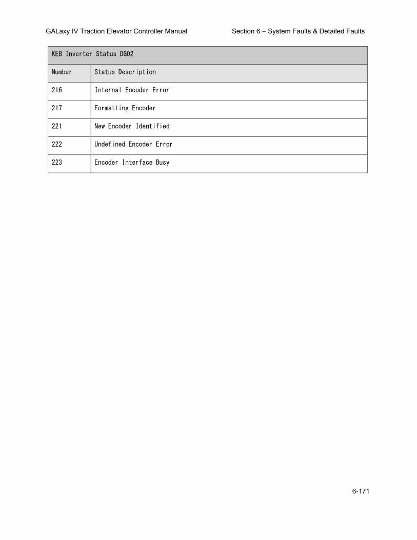
GALaxy IV Traction Elevator Controller Manual Section 6 – System Faults & Detailed Faults
6-171
KEB Inverter Status DG02
Number Status Description
216 Internal Encoder Error
217 Formatting Encoder
221 New Encoder Identified
222 Undefined Encoder Error
223 Encoder Interface Busy

GALaxy IV Traction Elevator Controller Manual Section 7 – Adjustable Variables
7-1
Section 7 – Adjustable Variables
7.1 Main CPU Adjustable Variables
7.1.1 Car Motion Submenu
Field Variable Min Max Initial Units Description
Table 7-1: Car Motion
Acceleration 50 300 92 fpm/s Acceleration Rate. The constant acceleration rate to reach top speed.
Access DT Dist 0 120 24 inches
Access DT Distance. Distance from DT limit for the bottom access limit to be software activated. The controller counts pulses from the DT limit.
Access Speed 0 75 35 fpm Access Speed. Car velocity while running on access .
Access UT Dist 0 120 24 inches
Access UT Distance. Distance from UT limit for the top access limit to be software activated. The controller counts pulses from the UT limit.
Adv Pre-Torque 0 1 0 -
Advance Pretorque. When set, the controller will pick the motor contactor and pretorque the motor when the door closes to the DLM limit. It is enabled to improve floor to floor times when pretorque is used. 0 = Off 1 = On
APS Dead Zone 0.1 0.5 0.25 inches APS Selector Dead Zone. This is the distance that the car can move without calling for a relevel.
Balanced Load 0 100 40 % Balanced Load. Percent load of the counterweight.
Decel Jerk 50 480 125 fpm/s/s Deceleration Jerk Rate. Maximum jerk rate to roll from top speed to constant deceleration.
Decel Rate 50 300 92 fpm/s
Deceleration Rate. The constant deceleration rate from top speed to leveling speed when stopping for a floor.

GALaxy IV Traction Elevator Controller Manual Section 7 – Adjustable Variables
7-2
Field Variable Min Max Initial Units Description
Table 7-1: Car Motion
Dist Feed Fwd 0 1.3 0 -
Distance Feed Forward. During the final approach to the floor, when using a tape selector, the number of pulses to calculate the velocity is 64 pulses per foot. So during this time, if the CPU does not see a distance change, it calculates the distance the car should move over the next ten millisecond period and then uses that value to calculate next velocity value. This value is a multiplier for what percentage of the velocity calculation to uses. When the next pulse comes in, the CPU calculates the velocity value as normal.
DL DeadZone Sel 0 15 3 -
DL Dead Zone Sensor. Adjusts the width of the door zone from four DL sensors. DL 1 is the outer most sensors whereas DL 4 is the inner most sensor. Each of the four bits, 0-3, of this parameter represents which DL sensor is being used. Bit 0 for sensor DL1 ... Bit 3 for sensor DL4. So a value of 3 will use sensor DL1 and DL2. (Used on tape applications). A value of 0 defaults to using DL1.
DON Start Ctrl 0 1 1 -
DON Start Ctrl. Drive ON Start Control. When set to 1 the controller starts the pattern delay after the drive on signal (DON) from the drive.
Drv Speed Mult 0.3 2 1 - Drive Speed Multiplier. Used for KEB Drive, to adjust the speed of the elevator.
EM Decel Lev 50 300 100 fpm/s Emergency Deceleration Rate to Leveling Rate.
Em Decel Rate 80 360 180 fpm/s
Emergency Deceleration Rate. The rate at which the elevator will decelerate when it is doing an emergency slowdown.
Encoder Dir 0 1 0 -
Encoder Direction for CAN Bus Encoder. Set to zero or one during Setup to get correct direction of pulses for the CAN encoder.
Encoder PPR 60 32000 2048 PPR Encoder Pulses Per Revolution. The number of pulses the motor encoder produces per revolution.
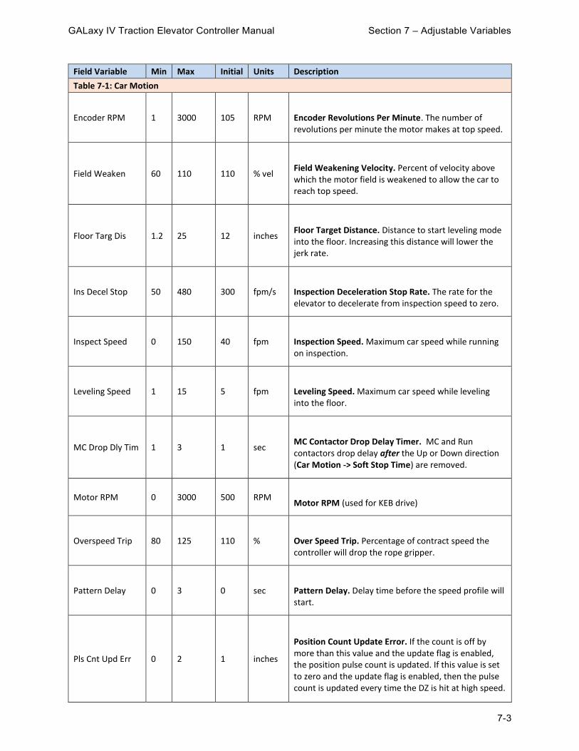
GALaxy IV Traction Elevator Controller Manual Section 7 – Adjustable Variables
7-3
Field Variable Min Max Initial Units Description
Table 7-1: Car Motion
Encoder RPM 1 3000 105 RPM Encoder Revolutions Per Minute. The number of revolutions per minute the motor makes at top speed.
Field Weaken 60 110 110 % vel
Field Weakening Velocity. Percent of velocity above which the motor field is weakened to allow the car to reach top speed.
Floor Targ Dis 1.2 25 12 inches
Floor Target Distance. Distance to start leveling mode into the floor. Increasing this distance will lower the jerk rate.
Ins Decel Stop 50 480 300 fpm/s Inspection Deceleration Stop Rate. The rate for the elevator to decelerate from inspection speed to zero.
Inspect Speed 0 150 40 fpm Inspection Speed. Maximum car speed while running on inspection.
Leveling Speed 1 15 5 fpm Leveling Speed. Maximum car speed while leveling into the floor.
MC Drop Dly Tim 1 3 1 sec
MC Contactor Drop Delay Timer. MC and Run contactors drop delay after the Up or Down direction (Car Motion -> Soft Stop Time) are removed.
Motor RPM 0 3000 500 RPM Motor RPM (used for KEB drive)
Overspeed Trip 80 125 110 % Over Speed Trip. Percentage of contract speed the controller will drop the rope gripper.
Pattern Delay 0 3 0 sec Pattern Delay. Delay time before the speed profile will start.
Pls Cnt Upd Err 0 2 1 inches
Position Count Update Error. If the count is off by more than this value and the update flag is enabled, the position pulse count is updated. If this value is set to zero and the update flag is enabled, then the pulse count is updated every time the DZ is hit at high speed.

GALaxy IV Traction Elevator Controller Manual Section 7 – Adjustable Variables
7-4
Field Variable Min Max Initial Units Description
Table 7-1: Car Motion
Pls Err Delay 1 10000 5000 1/sec
Position Count Update Error Delay. This number is the time delay from when DZ is hit until the input is read. The time delay parameter, times the current speed of the car, is used to estimate the number of pulses the count will change during the turn on time of the DZ input.
Pos Count Upd 0 7 0 -
Position Count Update Flag. The pulse count is checked every time the DZ input is hit. +1 = Update the DPP floor count as the elevator passes by a landing and hits DZ. +2 = Interrupt the CPU when DZ hit otherwise the update is done during the loop time (roughly 1 msec). +4 = Update every time the DZ is hit and the car is at constant speed regardless of the pulse count update error value.
Preopen Delay 0 3200 0.5 sec
Preopen Delay. Delay time to preopen the door starting from when the car reaches 3 inches from dead level and the door can safely be opened.
Recovery Speed 15 100 25 fpm Recovery Speed to the nearest floor.
Relev Pat Dly 0 3 0 sec Relevel Pattern Delay. Delay time before speed profile will start on a relevel.
Relev St Time 0 2 0 sec
Relevel Start Velocity Hold Time. If relevel start speed is set to a non zero value, controller will use that value for the speed before going into relevel velocity This parameter controls how long we stay in Relevel Start Velocity
Relev Strt Spd 0 15 0 fpm
Relevel Start Speed. Maximum starting velocity for a relevel. Car will stay in relevel Start speed for a time set by parameter ' Relev St Time ' and then switch to relevel Speed.
Relevel Speed 1 15 6 fpm Relevel Speed. Maximum car speed during releveling operation.
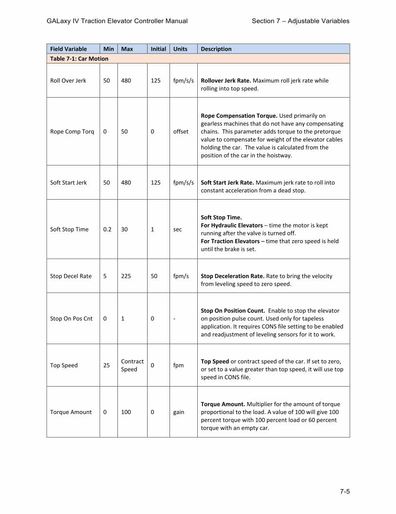
GALaxy IV Traction Elevator Controller Manual Section 7 – Adjustable Variables
7-5
Field Variable Min Max Initial Units Description
Table 7-1: Car Motion
Roll Over Jerk 50 480 125 fpm/s/s Rollover Jerk Rate. Maximum roll jerk rate while rolling into top speed.
Rope Comp Torq 0 50 0 offset
Rope Compensation Torque. Used primarily on gearless machines that do not have any compensating chains. This parameter adds torque to the pretorque value to compensate for weight of the elevator cables holding the car. The value is calculated from the position of the car in the hoistway.
Soft Start Jerk 50 480 125 fpm/s/s Soft Start Jerk Rate. Maximum jerk rate to roll into constant acceleration from a dead stop.
Soft Stop Time 0.2 30 1 sec
Soft Stop Time. For Hydraulic Elevators – time the motor is kept running after the valve is turned off. For Traction Elevators – time that zero speed is held until the brake is set.
Stop Decel Rate 5 225 50 fpm/s Stop Deceleration Rate. Rate to bring the velocity from leveling speed to zero speed.
Stop On Pos Cnt 0 1 0 -
Stop On Position Count. Enable to stop the elevator on position pulse count. Used only for tapeless application. It requires CONS file setting to be enabled and readjustment of leveling sensors for it to work.
Top Speed 25 Contract Speed
0 fpm
Top Speed or contract speed of the car. If set to zero, or set to a value greater than top speed, it will use top speed in CONS file.
Torque Amount 0 100 0 gain
Torque Amount. Multiplier for the amount of torque proportional to the load. A value of 100 will give 100 percent torque with 100 percent load or 60 percent torque with an empty car.

GALaxy IV Traction Elevator Controller Manual Section 7 – Adjustable Variables
7-6
Field Variable Min Max Initial Units Description
Table 7-1: Car Motion
Torque Down Amt
0 100 0 gain
Torque Down Amount. Torque Amount for down direction of travel. Multiplier for the amount of torque proportional to the load. A value of 100 will give 100 percent torque with 100 percent load or 60 percent torque with an empty car. If this value is set to zero then the Torque Amount parameter above will be used for both up and down direction.
Torque Ramp Tim
0 1 0 sec
Torque Ramp Time. The amount of time for the torque to ramp up prior to the elevator leaving the floor during pattern delay.
UL DeadZone Sel 0 15 3 -
UL Dead Zone Sensor. Adjusts the width of the door zone from four UL sensors. UL 1 is the outer most sensors whereas UL 4 is the inner most sensor. Each of the four bits, 0-3, of this parameter represents which UL sensor is being used. Bit 0 for sensor UL1 … Bit 3 for sensor UL4. So a value of 3 will use sensor UL1 and UL2. (Used on tape applications). A value of 0 defaults to using UL1.
7.1.2 Car Brake Submenu
Field Variable Min Max Initial Units Description
Table 7-2: Car Brake
Brake Drop Del 0 5 0.1 sec
Brake Drop Delay. Delay time to drop the brake after the car has stopped and is dead level at the floor.
Brake Hold Volt 20 400 160 volts
Brake Hold Voltage. Voltage to hold the brake for the remainder of the run after Brake Pick Time expires.

GALaxy IV Traction Elevator Controller Manual Section 7 – Adjustable Variables
7-7
Field Variable Min Max Initial Units Description
Table 7-2: Car Brake
Brake Opto Dly 0 7372 5500 3686/msec
Brake Opto Delay. The SCR Brake board trigger circuit uses optocoupler devices that have a turn on delay of roughly 1 millisecond but can vary from part to part and vary from different input filtering. This parameter is used to compensate for different turn on delays to start of triggering of the SCRs. Only change this value at the advice of a G.A.L. Technician.
Brake Pick Del 0 5 0 sec Brake Pick Delay. Delay time to pick the brake after the run relay is energized.
Brake Pick Time 0.1 6 3 sec Brake Pick Time. Duration of applied brake pick voltage before changing to the hold voltage.
Brake Pick Volt 20 400 230 volts
Brake Pick Voltage. DC Voltage to pick the brake. Brake voltage will start at Brk Pick Start voltage and then ramp to pick voltage.
Brk AC L-L Volt 80 300 240 volts Brake AC Line to Line Voltage. AC input voltage to the brake board.
Brk Drop Rate 0 5 0 sec Brake Drop Rate Time. Time value for brake to ramp from start voltage to zero.
Brk Drop Start 0 1 0 -
Brake Drop Timing During Leveling. 0 = Normal brake drop 1 = Early drop selected
Brk Drop Volt 0 200 0 volts Brake Initial Drop Voltage. DC Voltage to start the brake drop. Brake voltage will start at this value and then ramp down to zero volts.
Brk Phase Inp 0 1 0 -
Brake Phase Input. 0 = Single phase 1 = 3 phase.

GALaxy IV Traction Elevator Controller Manual Section 7 – Adjustable Variables
7-8
Field Variable Min Max Initial Units Description
Table 7-2: Car Brake
Brk Pick Rate 0 2 0 sec Brake Pick Rate Time. Time value for brake to ramp from start voltage to Brake Pick Volt.
Brk Pick Start 0 400 0 volts
Brake Pick Start Voltage. Initial DC Voltage to pick the brake. Brake voltage will ramp to Brake Pick Volt.
Brk Relev Rate 0 2 0 sec Brake Relevel Rate Time. Time value for brake to ramp from relevel start voltage to relevel voltage.
Brk Relev Start 0 400 0 volts
Brake Relevel Start Voltage. Initial DC Voltage to pick the brake on a relevel. Brake voltage will ramp to relevel voltage.
Brk Relev Volt 10 400 230 volts
Brake Relevel Voltage. Brake voltage applied on the brake coil during a relevel. This parameter is useful to have a partial brake lift on relevel. Relevel brake voltage will start at relevel start voltage and then ramp to relevel voltage.
Brk Resistance 0.1 500 283 Ohms Brake Resistance. Resistance value measured on the brake coil in ohms.
EmBk Drop Dly 0 360 0 sec
Emergency Brake Drop Delay. Delay time to drop the brake after the car has stopped and is dead level at the floor.
EmBk Drop Rate 0 1.5 0 sec Emergency Brake Drop Rate Time. Time value for brake to ramp from start voltage to zero.
EmBk Hold Volt 0 400 160 volts
Emergency Brake Hold Voltage. Voltage to hold the emergency brake for the remainder of the run after Emergency Brake Pick Time has expired.
EmBk L-L VAC 80 300 240 volts Brake AC Line to Line Voltage. AC input voltage to the brake board.

GALaxy IV Traction Elevator Controller Manual Section 7 – Adjustable Variables
7-9
Field Variable Min Max Initial Units Description
Table 7-2: Car Brake
EmBk Opto Dly 0 7372 5500 3686/msec
Emergency Brake Opto Delay. The SCR Brake board trigger circuit uses optocoupler devices that have a turn on delay of roughly 1 millisecond but can vary from part to part and vary from different input filtering. This parameter is used to compensate for different turn on delays to start of triggering of the SCRs. Only change this value at the advice of a G.A.L. Technician.
EmBk Phase In 0 1 0 -
Emergency Brake Phase Input. 0 = Single phase 1 = 3 phase.
EmBk Pick Rate 0 2 0 sec
Emergency Brake Pick Rate Time. Time value for emergency brake to ramp from start voltage to pick voltage. Only used if two brake boards are installed.
EmBk Pick Tim 0 10 3 sec
Emergency Brake Pick Time. Duration of applied emergency brake pick voltage before changing to the hold voltage. Only used if two brake boards are installed.
EmBk Pick Volt 0 400 230 volts
Emergency Brake Pick Voltage. DC Voltage to pick the emergency brake. Brake voltage will start at start voltage and then ramp to pick voltage. Only used if two brake boards are installed.
Pwl Bk Off Tim 0 5 0 sec
Power Loss Brake Off Time. When Pwl Bk On Tim and Pwl Bk Off Tim are set to a non zero values, the timers are used to pulse the brake contactor output on and off while recovering the car with Power loss brake option.
Pwl Brk On Tim 0 5 1 sec
Power Loss Brake On Time. When Pwl Bk On Tim and Pwl Bk Off Tim are set to a non zero values, the timers are used to pulse the brake contactor output on and off while recovering the car with Power loss brake option.
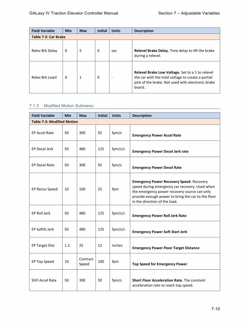
GALaxy IV Traction Elevator Controller Manual Section 7 – Adjustable Variables
7-10
Field Variable Min Max Initial Units Description
Table 7-2: Car Brake
Relev Brk Delay 0 5 0 sec Relevel Brake Delay. Time delay to lift the brake during a relevel.
Relev Brk LowV 0 1 0 -
Relevel Brake Low Voltage. Set to a 1 to relevel the car with the hold voltage to create a partial pick of the brake. Not used with electronic brake board.
7.1.3 Modified Motion Submenu
Field Variable Min Max Initial Units Description
Table 7-3: Modified Motion
EP Accel Rate 50 300 92 fpm/s Emergency Power Accel Rate
EP Decel Jerk 50 480 125 fpm/s/s Emergency Power Decel Jerk rate
EP Decel Rate 50 300 92 fpm/s Emergency Power Decel Rate
EP Recov Speed 10 100 25 fpm
Emergency Power Recovery Speed. Recovery speed during emergency car recovery. Used when the emergency power recovery source can only provide enough power to bring the car to the floor in the direction of the load.
EP Roll Jerk 50 480 125 fpm/s/s Emergency Power Roll Jerk Rate
EP SoftSt Jerk 50 480 125 fpm/s/s Emergency Power Soft Start Jerk
EP Target Dist 1.2 25 12 inches Emergency Power Floor Target Distance
EP Top Speed 10 Contract Speed
100 fpm Top Speed for Emergency Power
ShFl Accel Rate 50 300 92 fpm/s Short Floor Acceleration Rate. The constant acceleration rate to reach top speed.

GALaxy IV Traction Elevator Controller Manual Section 7 – Adjustable Variables
7-11
Field Variable Min Max Initial Units Description
Table 7-3: Modified Motion
ShFl Decel Rate 50 300 92 fpm/s
Short Floor Deceleration Rate. The constant deceleration rate from top speed to leveling speed when stopping for a floor.
ShFl SoftSt Jrk 50 480 125 fpm/s/s
Short Floor Soft Start Jerk Rate. Maximum jerk rate to roll into constant acceleration from a dead stop.
Short Fl Cntrl 0 7 0 -
Short Floor Control. 0 = Default is that the car relevels to the short floor. +1 = Car will make a run between very short floors instead of releveling. +2 = Short floor slowdown magnets between short floors (non-distance feedback). +4 = Mid Short floor slowdown magnets between short floors (non-distance feedback).
Short Fl Dist 10 72 30 inches
Short Floor Distance. Any floor less than this distance is considered a short floor. The short floor flag gets set and if preopening is enabled, it can be specifically disabled for the short floor run.
ShrtFl Decl Jrk 50 480 125 fpm/s/s
Short Floor Deceleration Jerk Rate. Maximum jerk rate to roll from top speed to constant deceleration.
ShrtFl Roll Jrk 50 480 125 fpm/s/s Short Floor Rollover Jerk Rate. Maximum roll jerk rate while rolling into top speed.
ShrtFl Targ Dis 1.2 25 8 inches
Short Floor Target Distance. Distance to start leveling mode into the floor. Increasing this distance will lower the jerk rate.

GALaxy IV Traction Elevator Controller Manual Section 7 – Adjustable Variables
7-12
7.1.4 Car Timers Submenu
Field Variable Min Max Initial Units Description
Table 7-4: Car Timers
Adv Door En Tim 0 240 0 sec
Advanced Door Enable Time. Door open advance enable time to open the opposite door when operating with non-simultaneous doors. If there is a request for both doors, instead of waiting for the first open door to close completely before opening the second door, the second door starts to open after the advance door enable time while the first door is closing.
Att Buz Delay 0 900 60 sec
Attendant Buzzer Delay. Buzzer sounds if a hall call is entered and the car has not started moving within this delay time. This function is disabled when set to zero.
AttBuz Off Time 0 30 0 sec
Attendant Buzzer Off Time. Cycle off time to turn attendant buzzer on and off once attendant delay time function has been meet (See ATT Buz Delay). Buzzer will stay on continuously if this timer set to zero.
AttBuz On Time 1 30 5 sec
Attendant Buzzer On Time. Cycle on timer to turn attendant buzzer on and off once attendant delay time function has been meet (See ATTBuz Delay).
Auto Swg DO Dly 0 10 1 sec Auto Swing Door Open Delay. Delay time to turn enable the auto swing door open output.
Car Call Dwell 1 60 2 sec Car Call Dwell. Door open dwell time when answering a car call only.
CB Door Time 1 3200 60 sec
Code Blue Door Time. Door time for Code blue operation once elevator is at the emergency floor before EMS is energized
Chime onCC Time
0.1 2 0.2 sec Chime on Car Call Time. Handicap buzzer on CC. Length of beep time.
CL Pulse Time 0 320 5 sec Car Lantern Pulse Time

GALaxy IV Traction Elevator Controller Manual Section 7 – Adjustable Variables
7-13
Field Variable Min Max Initial Units Description
Table 7-4: Car Timers
Door Delay Time 0 1.5 0 sec Door Delay Time. Delay time between DO and DC to switch when opening or closing the door.
Door Fail Time 10 3200 25 sec Door Fail Time. Time with power on the door without getting the door open limit.
EE Test Time 0 2 0.2 sec Electric Eye Test for Automatic Freight Doors
EE Time-out 0 3200 40 sec
Electric Eye Time-out Time. If the Electric Eye or detector edge is on continuously for this amount of time, it will be flagged as timed-out and the controller will ignore the EE input and close the door on nudging. When set to zero, this feature is disabled.
Fault Time 0 10 2 sec Fault Time. Delay time before allowing the car to run after a fault occurs.
FR DC Time-out 1 3200 1 sec
Freight Door Close Time-out. The amount of time prior to closing the doors on automatic freight door operation.
FR Pwr DO Time 0 30 1 sec
Freight Door Power Door Open Time. The amount of time to turn on the power door open relay on automatic freight door operation.
Gen/Lt/Fan Time 30 3200 360 sec
Generator Run/Cab Light/Fan Time. Length of time to leave the generator running or the Cab light and fan on after there is no longer a demand to run.
GOV Rst Pls Tim 1 15 2 sec Governor Reset Pulse Time
Grip/EBK Rset T 0 20 4 sec
Gripper/Emergency Brake Reset Time. The amount of time it takes for the rope gripper to reset on power-up.
Hall Call Dwell 1 60 4 sec Hall Call Dwell. Door open dwell time when answering a hall call or both a hall and car call.

GALaxy IV Traction Elevator Controller Manual Section 7 – Adjustable Variables
7-14
Field Variable Min Max Initial Units Description
Table 7-4: Car Timers
Hall Lant Dly 0 15 0 sec
Hall Lantern Delay Time. By default, when set to zero, hall lanterns go off as soon as the car starts to slow down to arrive at a floor. When set to a nonzero value, this will be used as a timer for the hall lantern to go off prior to arriving at the floor. For example, if set to three seconds, hall lanterns will turn on approximately three seconds before the car arrives to the floor regardless of the speed of the car. We recommend to set this parameter for high speed cars.
Handicap Dwell 1 120 25 sec Handicap Dwell. Extended door time from pressing the ED button in the car.
HEOF Auto Rst T 0 3200 0 sec
HEOF Auto Reset Time. When the hall elevator off function is activated from the HEOF input being turned on, the car will be taken out of service until the input is turned off. Once the input is off, the car will stay out of service until this timer times out.
IND Rcl2Lby tmr 10 60 20 sec Independent Recall to Lobby Timer. Recall delay for car in independent when 'IND Rcl to Lby ' is set.
Lant Off Time 0 2 0.2 sec
Lantern Off Time. Used for double stroke gongs. The lantern off time is the delay time after the lantern first turns on until it turns off.
Lant On Time 0 2 0.7 sec
Lantern On Time. Used for double stroke gongs. The lantern will turn on, turn off and then turn on again. The Lantern on time is the delay time from when the lantern first turns on until it turns on the second time.
Learn HW Stall 1 3200 30 sec
Automatic Hoistway Learn Stall Time. The time required for a hoistway learn is calculated by the number of floor at an average height of 12.5 feet. This stall time value is added to the calculated value for the maximum time allowed for the auto hoist way learn to run. If floor heights are taller or if there is a blind shaft, this timer may need to be increased to the additional floor height times 1.2 (multiplier for car running at 30fpm). For a blind shaft of 50 feet then use a timer value of 50 * 1.2 = 60.0 seconds.

GALaxy IV Traction Elevator Controller Manual Section 7 – Adjustable Variables
7-15
Field Variable Min Max Initial Units Description
Table 7-4: Car Timers
Lobby Dwell 1 60 5 sec Lobby Dwell. Door open dwell time for a car at the lobby.
ManDoor Buz Dly 0 900 0 sec
Manual Door Buzzer Delay. On a car with manual doors, sound the buzzer if the door is left open and a call is entered after this time delay. This function is disabled when set to zero.
Max Door Hld T 0 3200 0 sec
Maximum Door Hold Time to be allowed when the extended dwelling input (ED) is pressed. If set to zero, there will be no limit on how long the car will be held on ED. When set to a value, this will be the maximum allowed time for the car to held by ED input, then car will go on regular dwelling timers (car or hall call dwelling timers)
Non Interfer T 1 60 2 sec Non-Interference Time. Time between when you stop and when you can run again.
Nudging Time 20 3200 60 sec Nudging Time. Delay time for a door to be held before going into nudging.
OSER BTFlr Tim 0 900 60 sec
Out of Service Between Floors Time. Timer to control the OSERL output. Used with OSERL Control Option 1 for 'between floors for over a minute' set to 2.
OSER Ncall Tim 0 900 600 sec
Out of Service Not Responding to Calls Time. Timer to control the OSERL output. Used with OSERL Control Option 1 for 'not responding to calls' set to 1.
OSER Sopen Tim 0 900 60 sec
Out of Service Safety String Open Time. Time to control the OSERL output. Used with OSERL Control Option 1 for ' SS open' set to 4.
Pas Chime Time 0.2 2 0.5 sec Floor Passing Chime Time. Length of time the floor passing chime will sound when a floor is passed.
RC dropfail Tim 0.5 5.5 0.5 sec
Retiring Cam Drop Fail Time. Retiring cam drop fail safe delay for manual doors. Time it waits when car arrives to the floor before it drops the output.
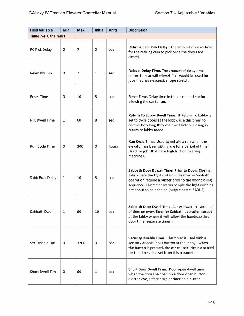
GALaxy IV Traction Elevator Controller Manual Section 7 – Adjustable Variables
7-16
Field Variable Min Max Initial Units Description
Table 7-4: Car Timers
RC Pick Delay 0 7 0 sec
Retiring Cam Pick Delay. The amount of delay time for the retiring cam to pick once the doors are closed.
Relev Dly Tim 0 2 1 sec
Relevel Delay Time. The amount of delay time before the car will relevel. This would be used for jobs that have excessive rope stretch.
Reset Time 0 10 5 sec Reset Time. Delay time in the reset mode before allowing the car to run.
RTL Dwell Time 1 60 8 sec
Return To Lobby Dwell Time. If Return To Lobby is set to cycle doors at the lobby, use this timer to control how long they will dwell before closing in return to lobby mode.
Run Cycle Time 0 300 0 hours
Run Cycle Time. Used to initiate a run when the elevator has been sitting idle for a period of time. Used for jobs that have high friction bearing machines.
Sabb Buzz Delay 1 10 5 sec
Sabbath Door Buzzer Timer Prior to Doors Closing: Jobs where the light curtain is disabled in Sabbath operation require a buzzer prior to the door closing sequence. This timer warns people the light curtains are about to be enabled (output name: SABUZ)
Sabbath Dwell 1 60 10 sec
Sabbath Door Dwell Time. Car will wait this amount of time on every floor for Sabbath operation except at the lobby where it will follow the handicap dwell door time (separate timer).
Sec Disable Tim 0 3200 0 sec
Security Disable Time. This timer is used with a security disable input button at the lobby. When the button is pressed, the car call security is disabled for the time value set from this parameter.
Short Dwell Tim 0 60 1 sec
Short Door Dwell Time. Door open dwell time when the doors re-open on a door open button, electric eye, safety edge or door hold button.

GALaxy IV Traction Elevator Controller Manual Section 7 – Adjustable Variables
7-17
Field Variable Min Max Initial Units Description
Table 7-4: Car Timers
Shutdn Alarm T 5 1500 120 sec Shutdown Alarm Timer
Stall Time 20 3200 60 sec Stall Time. Maximum time a run is requested but the car is not moving.
VIP Door Time 1 3200 20 sec
VIP Door Time. The amount of time the car will park at the VIP recall floor prior to going to automatic service.
Y Delta Time 1 5 1.5 sec
Y-Delta Time. Transfer time to change motor from Y start to Delta run. Timer also used for DEL or MCX turn on time with controllers without y-delta starters.
7.1.5 Car Options Submenu
Field Variable Min Max Initial Units Description
Table 7-5: Car Options
# Load Sensors 1 16 20 sen Number Of Rope Load Sensors to use with new Micelect load weigher.
Arrival Lant 0 1 0 - Arrival Lantern. 1 = activate lant/gong without onward call.
Behind CC Canc 0 1 0 -
Behind Car Call Cancel. When enabled the elevator will not latch any car calls in the opposite direction of travel.
Binary Preset 0 1 0 -
Binary Preset. 0 = Update the car position count based on the binary preset when the car recovers into a floor. 1 = Always update the car position count based on binary preset when the position doesn’t not match.

GALaxy IV Traction Elevator Controller Manual Section 7 – Adjustable Variables
7-18
Field Variable Min Max Initial Units Description
Table 7-5: Car Options
Brake Lift Sw 0 2 1 -
Brake Lift Switch. If set to 1 or 2 a brake lift switch fault is detected. 0 = The Brake switch is ignored. 1 = The car is prevented from running if the brake does not drop or if the brake did not pick on the previous run. The car is allowed to run after the brake drops. 2 = The rope gripper will set if the brake does not drop and then can only be reset by placing the car on inspection and back to automatic.
Cab Lant Ctrl 0 2 0 -
Cab Lantern control. The default is for the cab lanterns to go off when the door is fully open. This parameter allows the cab lanterns to go off earlier. +1 = Ring cab lanterns as soon as door starts to open +2 + Ring the cab lanterns when the door reaches DPM point.
Cl Gate No Pref 0 1 0 -
Close Gate (Swing Door) when No Onward Preference. The gate on a swing door normally stays open until a call is placed. This bit causes the gate to close while the car is sitting at the floor.
COP/Remote CC 0 7 0 -
COP/Remote Car Call Select. 0 = Both COP and Remote Car Call Station used to enter calls. +1 = Separate: COP only or Remote CC only used to enter car calls.+2 = C-R: Car calls entered on the COP sets the acknowledgment light on the Remote station. +4 = R-C: Car calls entered on the Remote station sets the acknowledgment light on the COP.
COP/Remote Dis 0 14 0 -
COP/Remote Disable. +1 = Up Direction Disable COP +2 = Down Direction Disable COP +4 = Up Direction Disable Remote Panel +8 = Down Direction Disable Remote Panel
DCB Canc Dwell 0 1 0 -
Door Close Button Cancel Dwell Time. When this parameter is set to 1 we do not allow DCB to cancel the door dwell time. It basically disables DCB to shorten door dwell time.

GALaxy IV Traction Elevator Controller Manual Section 7 – Adjustable Variables
7-19
Field Variable Min Max Initial Units Description
Table 7-5: Car Options
DO No Actv DOL 0 1 0
Door Open Output when not Active DOL. 0 = When the door is fully open and hits the DOL, the DO is turned off and stays off even if the door drifts off of DOL. 1 = With this bit set, the DO output will turn on any time the DOL is lost.
DOB Over Nudg 0 1 0
DOB Over Nudging. If set the door open button will open the door when the door is nudging closed.
DoorOpenL Ctrl 0 16 0 -
Door Open Light Control. The way 'DoorOpenL Ctrl' parameter works is as below: +1 = Set OPENL on phase 1 completed +2 = Set OPENL on RTL return to lobby +4 = Set OPENL on emp returned home with doors open, also sets OPENL on emp and selected to run +8 = Set OPENL on when Lobby Floor +16 = Set OPENL all the time
Double Stroke 0 1 1 - Double Stroke Gong Selection. Select 1 or 2 gongs for down hall calls. 0 = 1 gong1 = 2 gongs.
Drive Rdy Flts 1 10 5 count Drive Ready Fault Reset Count. Number of times the drive can be reset in a 20 minute time period.
DZ gripper ctl 0 1 0 -
DZ Gripper Trip Control. 0 = The gripper will detect "out of the door zone" from DZ only. 1 = The controller will use DZ anded with DZA (both activated) which changes the trip zone from 2 inches to 6 inches.
EE Cancel Dwell 0 1 0 -
Electric Eye Cancel Dwell. By turning this parameter on you disable the short dwelling door time from the electric eye signal (EE). By default the short dwelling time is enabled.

GALaxy IV Traction Elevator Controller Manual Section 7 – Adjustable Variables
7-20
Field Variable Min Max Initial Units Description
Table 7-5: Car Options
EM Brake Sw 0 1 0 -
Emergency Brake Switch Control 0 = Don't start if brake switch does not pick 1 = Ignore brake switch on start
Enc Dir Flt Dis 0 1 0 -
Encoder Direction Fault Disable. 0 = Enables fault 1 = Disables fault
GOV Gripper/EBK
0 1 0 -
Governor Switch Gripper/Emergency Brake Trip Control. 0 = Sets and latches a gripper fault immediately when the governor switch is opened. 1 = Latches the gripper fault only if the governor switch is opened while the car is traveling at contract speed or above 150 fpm. When the gripper fault is latched it must be reset from the LCD interface for the car to run.
Griper/EBK Buz 0 1 0 -
Gripper/Emergency Brake Buzzer. Turn on buzzer if there is an active rope gripper or emergency break fault
Gripper/EBK Trip 0 3 3 - Gripper/Emergency Brake Trip. 0 = Off+1 = Safety Processor Speed+2 = Overspeed
HB/PI Dis NV Fl 0 1 0 -
Handicap Buzzer/PI Display Control. When set to 1, do not sound HB or update floor PI when passing an invalid floor.
Hndcap Time Flr Bottom Floor
Top Floor
1 floor
Handicap Time Floor. If the job is configured to have an extended door input at a hall station, this parameter configures the floor number when parameter will change door timing. Follows Car Timers > Handicap Dwell timer. It will operate for EDHL only
Invert BLS 0 1 0 -
Invert Brake Lift Switch. When set inverts the logic for the brake lift switch to use a normally closed switch instead of normally open.

GALaxy IV Traction Elevator Controller Manual Section 7 – Adjustable Variables
7-21
Field Variable Min Max Initial Units Description
Table 7-5: Car Options
Invert CLF 0 1 1 -
Invert the logic for the Car Light / Fan. 0 = Car light / fan is normally open. 1 = Car light / fan is normally closed.
Invert ISER 0 7 0 -
Invert In Service Output. 1 = The in service light output is turned off when the car is in service instead of turned on. 2 = The ISER output will function as an elevator in use light. 4 = The output functions as out of service from a shutdown and does not include independent, inspection or recovery mode.
Lant Pref Dly 0 3 0 sec
Lantern Preference Change Delay. When the direction preference for the elevator changes, we clear the lanterns and wait for this amount of time before the lanterns are turned on again.
Level Fault Cnt 3 10 3 count
Level Fault Count. Maximum count of consecutive relevel tries when a relevel error is detected. A relevel error is detected when the brake is dropped and the car moves out the level zone.
Leveling Fault 0 1 0 -
Leveling Fault Effect. 0 = Drop everything 1 = Set emergency brake or gripper when a leveling fault occurs. It will have to be manually reset.
Lim Dir Flt Dis 0 1 0 -
Limit Direction Fault Disable. Controller confirms the car direction of travel as it hits the terminal limits. 0 = Enables fault 1 = Disables fault
Load Rope Bal % 0 100 5 % Load Rope Balance Percent

GALaxy IV Traction Elevator Controller Manual Section 7 – Adjustable Variables
7-22
Field Variable Min Max Initial Units Description
Table 7-5: Car Options
LobbyLan NCU/IR 0 1 0 -
Lobby Lantern NCU/IR. 0 = Light the lanterns on IR service at each floor. The lantern will not light at the lobby if next up operation is selected because the IR car will not be selected to be the next up car. 1 = The IR car will light the lantern at all the floors and the lobby even with the system on Next Up operation.
Min Door Tim En 0 1 0 -
Minimum Door Time Enable. When set to 1, the minimum door time for a car call or a hall call is set from the car or hall call dwell timers and cannot be shortened by the Door Close button.
NCU Lant Ctrl 0 3 0 -
Next Up Direction Lantern Control. +1 = Turn off hall lantern after next up time. +2 = Turn off cab lantern after next up time.
NCU Pref Ctrl 0 1 0 -
Next Up Preference Control. When set allows direction preference to change before the door starts to close after the next up door time.
No HC Door Reop 0 3 0 - No Hall Call Button Door Reopen. When set do not reopen the door from a hall call.
Non-Simul Doors 0 2 0 -
Non-Simultaneous Doors. 0 = Both front and rear doors will open at the same time if there is a demand at both the front and rear openings. 1 = Front doors will open first before the rear doors open if there is a demand to open. 2 = The rear doors will open first before the front doors open if there is a demand to open.
Nudge Dis Ctl 0 7 0 -
Nudging Disable Control. +1 = Do not turn on the NUD output when doors are in nudging close mode, basically you are disabling nudging output. +2 = When doors are in nudging close mode and SE input is ON, keep doors open and also keep FB/NB output latched. +4 = Sound the nudging buzzer but do not close the doors on nudging.

GALaxy IV Traction Elevator Controller Manual Section 7 – Adjustable Variables
7-23
Field Variable Min Max Initial Units Description
Table 7-5: Car Options
Nudge No Calls 0 1 0 -
Nudge with No Calls. If set to a 1 the doors will close on nudging even if the elevator has no onward calls.
OSERL OutCtrl 1 0 7 0 -
Out of Service Light Control +1 = Not responding to calls +2 = Between floors for over a minute +4 = SS open. When this parameter as well as OSERL OutCtrl 2 is set to zero, the output will just operate as an Out of service light.
OSERL OutCtrl 2 0 1 0 -
Out of Service Light Control 2 + 1= Alarm. When this parameter as well as OSERL OutCtrl 2 is set to zero, the output will just operate as an Out of service light.
Preopen Doors 0 3 0 -
Preopen Doors. +1 = Will enable preopening of the doors. If retiring cam used with auto door, RCM will also turn on at the preopening point. +2 = Exclude short floors.
Rad Pos Ind 6 48 6 inches
Radial Position Indicator. Used for radial Position indicator output. It adjusts the range for the distance from the floor where the position indicator outputs should turn on and off
RCF out enable 0 1 0 -
Retiring Cam for Freight Output Enable. When you turn on this parameter we show a retiring cam output in controller, RCF, that mirrors the signal from RCM. You need to reboot CPU every time you change this parameter for changes to take effect.

GALaxy IV Traction Elevator Controller Manual Section 7 – Adjustable Variables
7-24
Field Variable Min Max Initial Units Description
Table 7-5: Car Options
RCM Control 0 3 0 -
Retiring Cam Control. 1 = Hold the retiring cam up at the floor if there is no pilot to open the door (manual doors). The retiring cam will drop after 5 minutes. 2 = RCM output turns on when DZ hit to advance the RCM ahead of the door open (auto door with retiring cam) otherwise the default is that RCM turns on when dead level. If preopening is set, RCM and DO turn on when DZ hit.
Secnd Risr Lant 0 1 0 -
Second Riser Lantern. Turn on cab lantern only when IR call answered. If this parameter is set, cab lanterns will only turn on when answering second riser calls.
Slip Det Dis 0 1 0 -
Slip Velocity Difference Disable. 0 = Enables fault 1 = Disables fault. Can only be disabled with code previous to A17.1 2010.
Slip Vel Diff 0 300 150 fpm
Slip Velocity Difference Fault Trip Value. This parameter determines Maximum allowable difference between Safety processor speed and controller speed.
SPB Dir Flt Dis 0 1 0 -
SPB Direction Fault Disable. 0 = Enables fault 1 = Disables fault
ULDL DirFlt Dis 0 1 0 -
UL/DL Direction Fault Disable. Controller confirms the car direction of travel when it passes the UL and DL door zone limits. 0 = Enables fault 1 = Disables fault
Vel Diff Dis 0 1 0 fpm
Velocity Difference Fault Disable. 0 = Enable sfault 1 = Disables fault

GALaxy IV Traction Elevator Controller Manual Section 7 – Adjustable Variables
7-25
Field Variable Min Max Initial Units Description
Table 7-5: Car Options
Velocity Diff 50 300 150 fpm
Velocity Difference. Maximum velocity difference between Encoder feedback and Demand Velocity. When the difference exceeds this setting, 'Velocity Diff Fault' will occur.
7.1.6 Service Options Submenu
Field Variable Min Max Initial Units Description
Table 7-6: Service Options
Access Bot Fl Bottom Floor
Top Floor
1 floor Access Bottom Floor. Floor for bottom access
Access Door Cls 0 1 0 -
Access Door Close. When on access operation the car runs with the Door Lock and GS open. By turning this parameter on, the car needs to have the gate switch signal ON in order to run. It should be used on hoistways where the car door will physically hit something if moved on access operation
Access Top Fl Bottom Floor
Top Floor
2 floor Access Top Floor. Floor for top access
Att Buz ctrl 0 1 1 -
Attendant Buzzer Control. 0 = Hall Calls only 1 = Hall Calls and Car Calls
Att CC from HC 0 1 0 -
Attendant Car Call from Hall Call. When set to 1 and the car is on Attendant service the respective car call will register when a hall call is registered.
CCPBS on Gp Sec 0 1 0 -
CCPBS On Group Car Call Security. This variable enables Car Call Push Button Security with group car call lockout switches. The configuration file setting for security type and car call push button security must also be set.
CCS on Sabbath 0 1 0 -
Car Call Security on Sabbath. When this parameter is enabled, Sabbath car calls will not latch on floors that have been secured using car call lockouts security

GALaxy IV Traction Elevator Controller Manual Section 7 – Adjustable Variables
7-26
Field Variable Min Max Initial Units Description
Table 7-6: Service Options
CEOF Control 0 7 0 -
Car Elevator Off Options: +1 = Recall +2 = Keep Door Open +4 = Turn off CLF (Car Light / Fan)
CEOF Control 2 0 15 0 -
Car Elevator Off Options 2: +1 = Keep doors Closed (do not cycle on reversal) +2 = Do not blink Elevator Off Light +4 = Elevator Off Auto Reset With Timer +8 = Enable Elevator Off Light to indicate the car finished recall of elevator off mode
DOB Over Sec 0 5 0 -
DOB Override Security. This parameter allows the car to open the door at a secured floor when the car is secured from the following conditions: 1 = The DOB will be allowed to open the door at any secured floor. 2 = The DOB can open the door at floors secured from group security floor mask table.3 = Allows the DOB to open the front door at floors secured by car call lockout security (switches or card reader).4 = Allows the DOB to open the rear door at floors secured from rear car call lockout security.5 = Allows the DOB to open the door at floors locked out by group security floor mask tables when the car is also on independent.
Door Hold Msg 0 1 0 - Door Hold Message. Set to enable Extended Door Time Message Indicator in CE Driver board
Elev Off Ret Fl 0 Top Floor
0 floor
Elevator Off Return Floor. Related to HEOF input. This setting is to be used in conjunction with 'Elev Off Ctl = +1'. If the elevator is configured to recall, this parameter will determine what floor the car should be recalled to in elevator off mode. If Parameter is set to zero, car will be returned to the Lobby.
Elv Off2 Ret Fl 0 Top Floor
0 Floor Hall Switch Elevator Off 2 Return Floor

GALaxy IV Traction Elevator Controller Manual Section 7 – Adjustable Variables
7-27
Field Variable Min Max Initial Units Description
Table 7-6: Service Options
Handicap Load 0 100 40 %
Handicap Load (Car Capacity). Percent load when above this value, the car may not have enough room for a person in a wheelchair. Cars with loads below this value would be given a preference to get an assignment at a floor requested by a handicap person.
HC Acknwldg Bzz 0 1 0 -
HC Acknowledge Attendant Buzzer - Buzz once ( for one sec) every time a call comes in. 0 = Disable 1 = Enable
HEOF Control 0 7 0 -
Hall Elevator Off Control. +1 = Recall car when key switch activated. +2 = Keep door open at the shutdown floor. +4 = Allow the cab light and fan to time-out even though the door is open but the car is shut down.
HEOF Control 2 0 15 0 -
Hall Elevator Off Options 2: +1 = Keep doors Closed (do not cycle) +2 = Do not blink HEOFL +4 = Auto Reset when input off and timer expires. +8 = Use HEOFL to indicate car finished recall.
HEOF Control 3 0 1 0 -
Hall Elevator Off Options 3. +1= Only activate if doors are closed. See other Hall Elevator Off Options as well.
HEOF Over Ind 0 1 0 - Hall Elevator Off Override Independent 1 = Wait for timer to expire and then recall the car
IND Door Cl CC 0 1 0 -
Independent Door Close Car Call. Enable to close the doors from a car call when the elevator is on independent.
Ind Over Sec 0 7 0 -
Independent Overrides Security. 1 = Allows independent service to override security car call lockouts. 2 = Override Security Floor Mask configurations 4 = Override remote car call station.

GALaxy IV Traction Elevator Controller Manual Section 7 – Adjustable Variables
7-28
Field Variable Min Max Initial Units Description
Table 7-6: Service Options
IND Rcl to Lby 0 1 0 -
Independent Recall to Lobby. Forces the car to recall to the lobby when on independent and no calls are made
Ins Door Close 0 1 0 -
Inspection Door Close. When set to 1, the door close output will turn on when the up or down inspection run button is pressed.
INSEC Outp Ctl 0 1 0 -
INSEC - In Security Output Invert. Output located on the car call security Board, 0 = Disable 1 = Enable
Load Antinuisan 0 100 20 % Load Anti-nuisance. Percent load when below this set point will cause the car to drop its car calls. This function is disabledwhen set to zero.
Load Bypass 0 100 60 %
Load Bypass. Percent load when above this set point will cause the car to bypass hall calls. This function is disabled when set to zero.
Load Dispatch 0 100 40 %
Load Dispatch. This set point is used as a trigger to activate Up Peak operations in the group. Each time the car leaves the lobby with a load greater than this value, the group will increment the Up Peak Trigger. This function is disabled when set to zero.
Load Overload 0 125 110 %
Load Overload. Percent load when above this set point will cause the car to go on overload operation (sit at the floor with the door open and the overload light on). When the load goes below this value, the car will automatically return to service. This function is disabled when set to zero.
LW Anti-nuisan 0 50 0 count
Load Weighing Anti-nuisance. Set to the maximum number of car calls that can been entered before all car calls are cancelled without the load switch LWA input on. Once the load switch is on, all car calls will stay latched. If set to 0, this function is disabled.

GALaxy IV Traction Elevator Controller Manual Section 7 – Adjustable Variables
7-29
Field Variable Min Max Initial Units Description
Table 7-6: Service Options
Manual Dir En 0 4 0 -
Attendant Manual Direction Enable. 1 = Works in conjunction with the ATTUP and ATTDN to determine direction of travel. 2 = Reads the ATTUP input and use it as a START button. 4 = Will not allow car calls to be registered until the door is fully closed.
No Psg Run Cnt 0 10 0 count
No Passenger Run Count. When set to a number other than zero, the car call antinuisance feature is activated. This count is the number of times the car will run from a car call without detecting that a passenger has broken the detector edge. Once the count is reached, all remaining car calls will be cancelled.
PI Serv Msg 1 0 Max Service
0 Service Number
PI Service Message 1. When the car service matches this number, user message 1 is sent to the PI display. This will correspond to user PI display message 17.
PI Serv Msg 2 0 Max Service
0 Service Number
PI Service Message 2. When the car service matches this number, user message 2 is sent to the PI display. This will correspond to user PI display message 18.
PI Serv Msg 3 0 Max Service
0 Service Number
Service Message 3 Display. Used for Custom messages. Need to be programmed by CE electronics and GAL for special messages.
Return To Lobby 0 7 0 -
Return to Lobby Option. +1 = Cycle door at lobby +2 = Cancel car calls when activated +4 = Cycle door on reversal.
RTL Door Selct 0 2 0 -
Return To Lobby Door Select. This variable allows you to specify door open type on 'Return to Lobby' service. 0 = The car will open only front door 1 = The car will open only rear doors 2 = The car will open both front and rear

GALaxy IV Traction Elevator Controller Manual Section 7 – Adjustable Variables
7-30
Field Variable Min Max Initial Units Description
Table 7-6: Service Options
Sabbath Dis Ctl 0 7 0 -
Sabbath Disable Control Variable - Add all numbers of the features you want to disable while in Sabbath operation: +1 = PIs +2 = Lanterns +4 = Directional arrows
Sabbath En Ctl 0 7 0 -
Sabbath Enable Control Variable. Set to zero disables all options. +1 = Allow IR momentarily to override Sabbath operation. +2 = Lobby Dwell time in Sabbath follows handicap door dwell time instead of the lobby dwell time. +4 = Wait until car is at lobby to turn off Sabbath operation
Sabbath En Ctl2 0 3 0 -
Sabbath Enable Control: +1 = When the car is placed on Sabbath operation, it waits to go to the lobby before switching to Sabbath Operation +2 = Uses the cab lanterns as directional arrows. This allows people on the hallway to know direction of travel for the elevator
Sabbath Mode 0 1 0 -
Sabbath Collective Mode. 0 = Down collective car calls 1 = Up collective car calls.
Sec Reassign CC 0 3 0 -
Security Reassign Car Call. Re-assign secured car call to opposite door. Used with security configuration cons.dat file setting: cons[SecFlCfg] = 2. 0 = Disabled +1 = If front CC are secured, reassign them as rear +2 = If rear CC are secured, reassign them as front.
Sec Recall 2 0 2 0 -
Security Recall Control 2. 0 = Out of group on first recall. 1 = Out of group on all recalls. 2 = No out of group recalls.
Security Floor 0 Top Floor
1 floor
Security Floor. The security recall floor. This is the floor where the security guard would be stationed. This floor would not be locked out when on security.

GALaxy IV Traction Elevator Controller Manual Section 7 – Adjustable Variables
7-31
Field Variable Min Max Initial Units Description
Table 7-6: Service Options
Security Recall 0 15 0 -
Security Recall Selection. 0 = No Recall +1 = Recall to Security Floor on activation of security +2 = Cycle front door once recalled to the Security Floor. +4 = Cycle rear door once recalled to the Security Floor. +8 = Always recall to security floor after each run.
Service LT CTL 0 30 0 Service Number
Service Light Control. When the configuration file parameter cons[servOUT] is set to 1 or 2, the service output SERVO will turn on when the car service matches the car service number in this parameter.
SR CCSec by Dir 0 2 0 -
Second Riser Car Call Security by Direction. Allows calls in the one direction but disables them in the other. 1 = Allow calls in the up direction (above the floor) but disable them going down 2 = Allow calls in the down direction (below the floor) but disable then going up.
Stop At Lobby 0 15 0 -
Stop at Lobby. 0 = Do not automatically stop at lobby, +1 = The car will stop at the lobby when the car is traveling up and the car is below the lobby floor. +2 = The car will stop at the lobby when the car is traveling down and the car is above the lobby floor. 3 = The car will stop at the lobby when traveling in either direction. +4 = Stop at lobby with any onward call past the lobby. +8 = Recall to the lobby
Vip Lant Ctrl 0 3 0 -
VIP lantern control: 0 = Do not ring lanterns on VIP 1 = Ring up or down lantern at VIP floor when the door is fully open 2 = Ring up or down lantern at VIP floor before the door is opened

GALaxy IV Traction Elevator Controller Manual Section 7 – Adjustable Variables
7-32
Field Variable Min Max Initial Units Description
Table 7-6: Service Options
VIP multi call 0 1 0 -
VIP Multiple Calls. 0 = VIP feature works as single call 1 = The car will be allowed to make multiple VIP calls until no more car calls are entered and until the VIP sequence time-out timer is expired.
7.1.7 Emergency Services Submenu
Field Variable Min Max Initial Units Description
Table 7-7: Emergency Services
ALT Fire Floor Bottom Floor
Top Floor
2 floor Alternate Fire Floor.
Alt Rcl FS Off 0 3 0 -
Alternate Floor Recall Fire Service Off. +1 = Have the elevator recall back to the alternate floor when the lobby fire switch is turned to the off position and car recalled to the main fire floor. +2 = Allows the car to return to the alternate landing even if sensor was reset
Aux. Fire Sw. 0 1 0 - Auxiliary Fire Switch. When set, the controller expects an auxiliary hall fire switch to be used.
CB Buzzer Ctrl 0 1 0 - Code Blue Buzzer Control: 1 = Turn on while in code blue recall
CB over FS 0 1 0 -
Code Blue Over Fire Service: +1 = Enable to have code blue prevent car from recalling in FS
CB Over Ind 0 1 0 - Code Blue Override Independent 1 = Wait for timer to expire and then recall the car
CB single call 0 1 0 -
Code Blue Single Car Call. 0 = Car on Code Blue operation allows multiple car calls on Hospital Service. 1 = Allow only a single call once placed on Hospital Service.

GALaxy IV Traction Elevator Controller Manual Section 7 – Adjustable Variables
7-33
Field Variable Min Max Initial Units Description
Table 7-7: Emergency Services
Cl Door F1 Rcl 0 1 0 -
Close Door after Fire phase 1 Recall. When set to 1, elevator will close the doors after phase 1 recall and reopen from a hall call (Denver Fire service amendment).
Em Power Floor Bottom Floor
Top Floor
1 floor Emergency Power Recall Floor.
EMS/HS after CB 0 1 0 -
EMS(Emergency Medical Service)/HS(Hospital Service) after Code Blue. This is a Code Blue bypass control. 0 = Car goes from Auto to Hospital service, bypassing the code blue sequence, when EMS switch is turned on. 1 = Hospital service only activates after a code blue recall.
EP Recovery Dir 0 1 0 -
Emergency Power Recovery Direction. Recover to the nearest floor on emergency power. 0 = Based on movement of the car when brake is picked. 1 = Based on load weighing device. Used when the emergency power recovery source can only provide enough power to bring the car to the floor in the direction of the load.
EPS Sel No Grp 0 2 0 -
Emergency Power Selection Switch Operation with no Group active. 0 = Run Automatic 1 = Recall first and then run automatic 2 = Recall only; do not run after recall.
F1 DC Time-out 10 60 20 sec
Fire Phase 1 Door Close Time-out. The amount of time it will take before the car doors start to close while the car is on Independent or Attendant service prior to recalling the elevator on Fire Phase 1.
F1 Door Dwell 1 90 60 sec
Fire Phase 1 Door Dwell Time. Fire Service Phase one complete dwell time when 'Cl Door F1 Rcl' parameter is set. (Denver FS phase1 dwell time)

GALaxy IV Traction Elevator Controller Manual Section 7 – Adjustable Variables
7-34
Field Variable Min Max Initial Units Description
Table 7-7: Emergency Services
F2 DOB ovr DCB 0 1 0 -
Fire Phase 2 Door Open Button Overrides Door Close Button. 1 = Allows Door Open Button to override Door Close Button on phase 2. 2 = Miami.
Fire Main Floor Bottom Floor
Top Floor
1 floor Fire Main Floor.
Fire Option 0 3 0 -
Fire Option. Recall Reset Selection: 0 = Reset fire service phase 1 after hall switch is turned off and car returns to fire floor. 1 = Reset phase 1 immediately after hall switch is turned off.
Fire Option 2 0 3 1 - Fire Option 2. +1 = Initiate a phase 2 recall only when the door is open (Chicago fire). +2 = Disable flashing FL on phase 2 (Chicago fire).
Fire Sw Loc 0 4 0 -
Fire Switch Location. Location of fire hall switch. 0 = Main/Alt Front 1 = Main Rear/Alt Front 2 = Main Front/Alt Rear 3 = Main/Alt Rear 4 = Set from Dispatcher Car selection.
FireL Emer Pwr 0 1 1 -
Fire Light Control During Emergency Power – Enable to cause the fire light FL to turn off if the car is not selected to run.
FireL OTS Ret 0 1 0 -
Fire Light Control for Out Of Service Cars: Enabling this parameter will turn off the fire light in the event the car cannot recall for being out of service. It could be in Earthquake, low oil, stall, etc.
Flash CB Light 0 1 0 - Flash Code Blue Light. When set to 1 the code blue light inside the car station will flash.

GALaxy IV Traction Elevator Controller Manual Section 7 – Adjustable Variables
7-35
Field Variable Min Max Initial Units Description
Table 7-7: Emergency Services
Hall Fire Light 0 4 0 -
Hall Fire Light. This variable controls the FLH output on the controller so it can be used for a hall fire light or a fire security override. The default operation is that FLH turns on while the car is on phase 1 or phase 2 fire service. +1 = On while phase 1 is in effect +2 = Flash FLH at 1 second intervals while activated +4 = FLH follows the Fire Light (FL) logic.
Hoistw Fire Ret 0 1 0 -
Hoistway Fire Sensor Return Floor Selection. 0 = Return to the Main fire floor 1 = Return to the Alternate fire floor.
HSV Door Cl CC 0 1 0 -
Hospital Service Close door Car Call. Close the doors from a car call when the car is on Hospital Service.
HWS 2 Fire Loc 0 1 50 - Fire Service Hoistway HWS2 Sensor Location 0 = Same HW 1 = Separate hoistway
HWS 2 Fire Ret 0 1 0 -
Second Hoistway Fire Service Sensor Return Option. 0 = Main recall floor 1 = Alternate recall floor.
MachRm Fire Ret 0 1 0 -
Machine Room Fire Sensor Return Floor Selection. 0 = Return to the Main fire floor 1 = Return to the Alternate fire floor.
Med CCS Ovrride 0 1 0 -
Medical Service Override Car Call Security. When set to 1, medical service car will override car call security.
Med Door Reopen
0 2 0 -
Medical Service Door Reopen. When car is in Medical Service, this parameter determines the door open sequence for re-open: 0 = Stop 1 = Constant pressure 2 = Momentary to DOL
Med Em Floor Bottom Floor
Top Floor
1 floor Medical Emergency Return Floor.

GALaxy IV Traction Elevator Controller Manual Section 7 – Adjustable Variables
7-36
Field Variable Min Max Initial Units Description
Table 7-7: Emergency Services
Med Em Sw Loc 0 1 0 - Medical Emergency Switch Location. Selects the switch location for the front or rear door.
Med Ind Ovrride 0 2 0 -
Medical Service Overrides Independent Control: 0 = Immediate 1 = After Delay 2 = No override
Rcl from F1 Alt 0 1 0 -
Recall From Fire Phase 1 Alternate Floor. 0 = If the car has returned to the alternate floor from a smoke sensor and when two fire hall switch are used, both must be on to recall the car from the alternate floor to the main floor. 1 = The car will recall from the alternate floor to the main floor from either hall fire key switch. (Set to 1 for Massachusetts fire service).
Recall Reset 0 3 0 -
Recall Reset Selection. 0 = Reset fire service phase 1 after hall switch cycled through reset and turned off and car returns to fire floor. 1 = Reset phase 1 immediately after hall switch is cycled through reset and then turned off. 2 = Reset fire service without cycling fire switch through reset but turned off only if the smoke sensors were not activated.
Recall Reset 2 0 1 0 -
Recall Reset Selection 2: 0 = Reset fire service phase 1 with car at any floor. 1 = Reset phase 1 only if car at fire recall floor.

GALaxy IV Traction Elevator Controller Manual Section 7 – Adjustable Variables
7-37
7.1.8 Group Dispatch Submenu
Field Variable Min Max Initial Units Description
Table 7-8: Group Dispatch
Alt Lobby Floor 1 Top Floor
1 floor
Alternate Lobby Floor. Galaxy groups could be configured to have an alternate lobby. Switching between regular lobby and alternate lobby could be done by means of LiftNet, Galileo, controller input or service timer. Once the alternate lobby is enabled, controllers will use this landing as the lobby floor for all dispatching purposes.
Alt Parking Fl 1 Top Floor
1 floor
Alternate Parking Floor. Normally, during parking operation, one elevator is always parked at the lobby. With alternate parking floor operation, a free car is parked at the alternate parking floor instead of the lobby floor. This operation is controlled by an input or from a service timer.
Asgn Park Fl DO 0 1 0 -
Assign Parking Floor with Door Open. By default we only park cars that have the doors closed after a time delay. this parameters allows to re-assign parking to cars with doors open as long as they do not have a direction to run.
Auto SVC tm-out 0 1 0 -
Auto Service Time-out. 0 = Disable 1 = Enable When this parameter is enabled and 'Auto SVC tot TM' (below) parameter time is set accordingly, each car is checked for answering assigned hall calls. If the car does not move to answer calls in the required time, it is put into AST service. Hall calls that are assigned to that car are reassigned to working cars in the group. The group then periodically assigns hall calls to the AST car to verify if it can be put back into the group for normal operation.
Auto SVC tot TM 10 3200 120 sec
Auto Service Time Out Time. This time in seconds is used in conjunction with 'Auto SVC tm-out' (above) and is the amount of time that the group will wait before setting a 'not moving/responding' car as timed out.
Dis Opp HC Time 10 30 10 sec Disable Opposite Hall Call Time: Specify amount of time the opposite hall call will be disabled.

GALaxy IV Traction Elevator Controller Manual Section 7 – Adjustable Variables
7-38
Field Variable Min Max Initial Units Description
Table 7-8: Group Dispatch
Disable Opp HC 0 15 0 -
Disable Opposite Hall Call after initial hall call is entered: When the first up or down hall call is hit, disable opposite call for the time set; +1 = Front hc riser+2 = Rear hc riser+4 = IR front hc riser+8 = IR rear hc riser
Dn Peak Contrl 0 1 0 -
Down Peak Control 0 = Normal down peak 1 = Heavy down peak
Dn Pk Trig Cnt 1 100 12 count
Down Peak Trigger Count. Number of down hall calls above the lobby that are set within the down peak trigger time to place the system on down peak operation.
Dn Pk Trig Time 0 3200 60 sec
Down Peak Trigger Time. The time interval to count the number of down hall calls above the lobby to activate down peak operation.
Down Peak Pool 0 Number Cars
0 car Down Peak Pool. Number of cars to be utilized for down peak.
Down Peak Time 0 3200 180 sec Down Peak Duration Time. The duration time for down peak operation once down peak is activated.
ETA Co CC Time 0 60 15 sec
ETA Coincident Car Call Time. Hall calls will be assigned to the car with the coincident car call unless the car without the coincident car call can reach the call faster than ETA Coincident Car Call Time.
ETA Min Time 0 60 6 sec
ETA Minimum Time. For a hall call to be assigned to a new car, the difference in ETA must be greater than the ETA Minimum Time.
Grp Timer Park 0 Number Cars
0 car
Group Service Timer Park Cars. This is the number of parking cars when parking is set from the Service Activation Timer for Group parking.

GALaxy IV Traction Elevator Controller Manual Section 7 – Adjustable Variables
7-39
Field Variable Min Max Initial Units Description
Table 7-8: Group Dispatch
High Priority FL 0 Top Floor
0 floor
High Priority Floor. When this parameter is set to a floor number other than zero the high priority operation is activated. If there is a call latched at the high priority floor and the timer set from the 'High Priority TM' (below) expires, the group will choose the best car by considering only car calls. It will remove all hall calls on that best car except for the priority floor hall call. The car will serve all car calls and then service the priority floor before being assigned another hall call from the group..
High Priority TM 6 254 60 sec
High Priority Time. Works in conjunction with parameter 'High Priority Floor' (above), it is the amount of time to wait before removing hall calls assigned to the selected best car.
Lobby Floor Bottom Floor
Top Floor
1 floor Lobby Floor.
Lobby Req Cntrl 0 1 0 -
Lobby Request Control. If the lobby request variable is set to non-zero, then that is how many cars are requested to the lobby all the time. When this flag is set to 1, the lobby request is only used when next up is active. Next Up can be active all the time, from a dedicated input or from Up Peak.
Lobby Request 0 Number Cars
0 car Lobby Request. Number of Cars Requested to the Lobby floor. Used with Next Car Up operation.
Next Car Up 0 7 0 -
Next Car Up. Set to 1 or 2 will activate the Next Car Up operation. +1 = The next up car will open its door at the lobby and keep it open. The car is allowed to leave the floor after the Lobby Dwell time expires but will remain at the floor with the door open until an onward call is assigned to it. +2 = The next up car will close its door after the Lobby Dwell time expires and go off of next up but will remain at the lobby. An up hall call at the lobby will cause the car to open its door and go on next up. +4 = Next up is activated on Up Peak detection only. Next up can also be activated from an input.
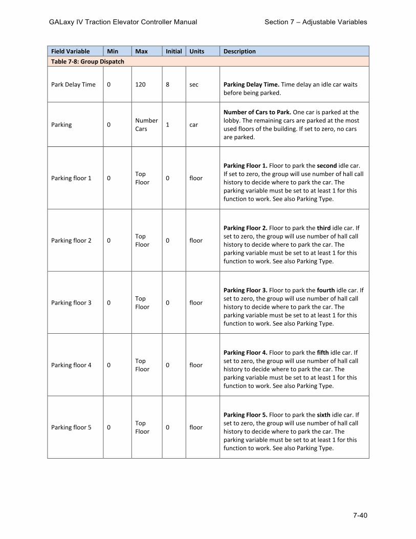
GALaxy IV Traction Elevator Controller Manual Section 7 – Adjustable Variables
7-40
Field Variable Min Max Initial Units Description
Table 7-8: Group Dispatch
Park Delay Time 0 120 8 sec Parking Delay Time. Time delay an idle car waits before being parked.
Parking 0 Number Cars
1 car
Number of Cars to Park. One car is parked at the lobby. The remaining cars are parked at the most used floors of the building. If set to zero, no cars are parked.
Parking floor 1 0 Top Floor
0 floor
Parking Floor 1. Floor to park the second idle car. If set to zero, the group will use number of hall call history to decide where to park the car. The parking variable must be set to at least 1 for this function to work. See also Parking Type.
Parking floor 2 0 Top Floor
0 floor
Parking Floor 2. Floor to park the third idle car. If set to zero, the group will use number of hall call history to decide where to park the car. The parking variable must be set to at least 1 for this function to work. See also Parking Type.
Parking floor 3 0 Top Floor
0 floor
Parking Floor 3. Floor to park the fourth idle car. If set to zero, the group will use number of hall call history to decide where to park the car. The parking variable must be set to at least 1 for this function to work. See also Parking Type.
Parking floor 4 0 Top Floor
0 floor
Parking Floor 4. Floor to park the fifth idle car. If set to zero, the group will use number of hall call history to decide where to park the car. The parking variable must be set to at least 1 for this function to work. See also Parking Type.
Parking floor 5 0 Top Floor
0 floor
Parking Floor 5. Floor to park the sixth idle car. If set to zero, the group will use number of hall call history to decide where to park the car. The parking variable must be set to at least 1 for this function to work. See also Parking Type.

GALaxy IV Traction Elevator Controller Manual Section 7 – Adjustable Variables
7-41
Field Variable Min Max Initial Units Description
Table 7-8: Group Dispatch
Parking floor 6 0 Top Floor
0 floor
Parking Floor 6. Floor to park the seventh idle car. If set to zero, the group will use number of hall call history to decide where to park the car. The parking variable must be set to at least 1 for this function to work. See also Parking Type.
Parking floor 7 0 Top Floor
0 floor
Parking Floor 7. Floor to park the eighth idle car. If set to zero, the group will use number of hall call history to decide where to park the car. The parking variable must be set to at least 1 for this function to work. See also Parking Type.
Parking Type 0 3 0 -
Parking Type. Determines the type of parking operation that is implemented by the group. 0 = Park free cars to floors with the most hall calls for that 15 minute period. 1 = Divide the hoistway by the number of cars and place a car in each zone starting with the lobby. 2 = Park cars according to the adjustable variable parking floor. Note that during parking, a car is always parked at the Lobby except when the option for alternate parking floor is selected through an input.
Parking Width 0 Top Floor
0 floor
Parking Width. The number of floor that a car is within to be considered parked at the parking floor. See also Parking Type.
Up Peak Contrl 0 1 0 -
Up Peak Control. 0 = Normal up peak 1 = Heavy up peak
Up Peak Pool 0 Number Cars
1 car Up Peak Pool. Number of cars to be utilized for up peak.
Up Peak Time 0 3200 180 sec
Up Peak Duration Time. The duration time for up peak operation once up peak is activated. If set to zero, up peak operation will never turn on.

GALaxy IV Traction Elevator Controller Manual Section 7 – Adjustable Variables
7-42
Field Variable Min Max Initial Units Description
Table 7-8: Group Dispatch
Up Pk CC Count 1 40 3 count
Up Peak Car Call Count. Number of car calls the car must have when leaving the lobby to count as an up peak trigger.
Up Pk Trig Cnt 1 100 3 count
Up Peak Trigger Count. The number of up peak triggers that are set within the up peak trigger time to activate up peak operation. Up peak triggers are counted when the car leaves the lobby with the load dispatch input set or with the more car calls than the up peak car call count.
Up Pk Trig Time 0 3200 60 sec Up Peak Trigger Time. The time interval to count the number of up peak triggers.
7.1.9 Group Options Submenu
Field Variable Min Max Initial Units Description
Table 7-9: Group Options
1st EP Run Car 0 Number Cars
1 car
First Emergency Power Run Car. This is the first car selected to run. If this car cannot run, the next consecutive car is selected.
1st Rcl EPSF 2 0 Number Cars
2 car
First Return Car Emergency Power Service Feeder 2. This will be the first car recalled in Emergency Power (the rest are done sequentially in a loop) for power feeder 2
1st Recall Car 0 Number Cars
1 car
First Recall Car. This is the first car allowed to recall during the emergency power recall sequence. The recall sequence continues in consecutive order and then loops around until all cars are recalled.
1st Run EPSF 2 0 Number Cars
2 car
First Run Car Emergency Power Service Feeder 2. This will be the first car selected to run on emergency power (the rest are done sequentially in a loop) for power feeder 2
2nd IR Car 0 Number Cars
0 car 2nd Inconspicuous Riser Car. Set this option to have a second car answer the Inconspicuous Risers.

GALaxy IV Traction Elevator Controller Manual Section 7 – Adjustable Variables
7-43
Field Variable Min Max Initial Units Description
Table 7-9: Group Options
ATT Pref Time 0 60 0 sec
Attendant ETA Preference Time. When set to non-zero, the car not on attendant service has this time added to its ETA time. This causes the attendant car to be given a preference for the hall call.
CB Button Loc 0 2 0 -
Code Blue Location: 0 = CB on CB 1 = CB on HCB 2 = CB on IR
CB IR Penalty 0 60 10 sec
IR Car Code Blue Penalty Time. This is used to calculate and give preference to cars in fully automatic operation
CB Rcll Any Car 0 1 0 -
Code Blue Recall Any Call. 0 = Disable 1 = Enables dispatcher to recall any car if Code Blue Cars 1 and 2 are not available. If you want to select any car as your primary option, make Code Blue Car and Code Blue Car #2 equal to zero and enable this setting.
CB Req Ind Car 0 1 0 -
Code Blue Request Independent Car. Code blue request for car on independent operation. Set to 1 in dispatcher, and in all cars so the car could be requested (flash EML) if the car is in independent mode.
CB Sel IR Car 0 1 0 - Code Blue Over IR Car
CB SRiser Car 0 Number Cars
0 car Code Blue Second Riser Car Select
CBlue Over Hugs 0 1 0 -
Code Blue Override HUGS Operation. Turns on option to have code blue operation override hugs operation. 0 = No override 1 = Override

GALaxy IV Traction Elevator Controller Manual Section 7 – Adjustable Variables
7-44
Field Variable Min Max Initial Units Description
Table 7-9: Group Options
Code Blue Car 0 Number Cars
0 car
Code Blue Car. When a code blue call is initiated, this will be the first car to be sent to respond. If car is not available, see variables 'Code Blue Car#2' and 'CB Rcll Any Car' for more options.
Code Blue Car#2 0 Number Cars
0 car
Code Blue Car #2. When a code blue call is initiated, this will be the car to be sent to respond in the event that first 'Code Blue Car' is not available, see variables 'Code Blue Car' and 'CB Rcll Any Car' for more options.
Dispatcher Car 0 Number Cars
0 car
Dispatcher Car. If set to 1, this car is allowed to become the dispatcher. In normal operation, this variable would be set to zero and car #1 would be the dispatcher. If car #1 is shut down, car #2 automatically becomes the dispatcher. During installation, it may be necessary to force car #3 (set Dispatcher Car to 3) or above to be the dispatcher until car #1 or #2 are brought on line.
Em Power Cars 1 Number Cars
1 car Number of Emergency Power Cars that can run at the same time on the emergency power source.
Emerg Dispatch 0 7 0 -
Emergency Dispatch. This parameter is applied to both the car that is selected as the dispatcher and also the non-dispatcher cars. If set to 1 and hall call power lost, the dispatcher car will set down hall calls above the lobby and up hall call at and below the lobby. For the non-dispatcher cars, if set to a 1, and communications is lost to the dispatcher car, the car will dispatch itself to down hall calls above the lobby and up hall calls below the lobby. The front hall call and rear hall call bits settings are only used for the dispatcher car and when set, if communication is lost to a particular hall call board, hall calls are set for the affected floors.
EMP ATT car 1st 0 1 0 -
Emergency Power Attendant Car First. Select and Prioritize the attendant car for running on emergency power service. It won't be recalled. After recall is complete for the group, it recovers and goes back in service

GALaxy IV Traction Elevator Controller Manual Section 7 – Adjustable Variables
7-45
Field Variable Min Max Initial Units Description
Table 7-9: Group Options
EmPwr Op Output 0 3 0 -
Emergency Power Operation LED. This parameter controls the group outputs for emergency power status for each car. 0 = Outputs are on for cars that are operational. 1 = Outputs on for cars on normal power. 2 = Outputs on for car on emergency power. 3 = Outputs on for cars that are being recalled.
EmPwr Pk Output 0 2 0 -
Emergency Power Park LED. This parameter controls the group outputs for emergency power parked status for each car. 0 = Cars are parked on emergency power. 1 = Cars are parked or selected to run.
EP Man Op TimOt 60 180 120 sec
Emergency Power Manual Operation Time-Out. Time that designated attendant car does not run for emergency power operation to sequence next car to recall.
EP Man Sel En 0 3 1 -
Emergency Power Manual Select Enable: 0 = If set to zero, the recall sequence is aborted and any moving car will stop at the next floor to allow the selected car to run. +1 = Car is selected to run when the currently selected car completes its recall. +2 = Makes the selected car wait for all the cars to recall before being selected to run.
EP Rcl Out en 0 1 0 -
Emergency Cars Finished Recalling Output Enable. It enables an output in the hall call board for Emergency Power Complete (EPCOM). This setting is only read in power up so after changing this setting you need to reboot the controller.
EP Recall Delay 0 3200 15 sec
Emergency Power Recall Delay Time. Time delay before the group starts the emergency power recall sequence.
EP Recover Tim 1 60 20 sec
Emergency Power Recovery Time. When elevators are in Emergency Power recall, this is the time that the dispatcher will wait for each car to recover to a floor. If the car is in the middle of a blind shaft, you need to calculate the time each car may take to get to a floor in emergency power recovery speed.

GALaxy IV Traction Elevator Controller Manual Section 7 – Adjustable Variables
7-46
Field Variable Min Max Initial Units Description
Table 7-9: Group Options
Grp CC Ovrride 0 1 0 -
Group Car Call Override. Normally visitor access allows the car call security to be overridden momentarily from a push button in an owners apartment. With this parameter set to 1, the security override works directly from a key switch input.
Grp CC Sec OvrT 1 240 60 sec
Group Car Call Security Override Timer. This is the amount of time that the car call security is overridden when a group car call security override button is pressed.
Handicap Wait 0 255 0 sec
Handicap Car Wait Time. Special operation that when a passenger presses a handicap hall button, the group adds this time to the ETA of all cars that do not have enough capacity. See Handicap Capacity in car options. Normally, if a car is at the floor of the handicap hall call, it will get the assignment regardless of the handicap capacity unless this value is set to 255.
HC Asg SecType 0 15 0 -
Hall Call Assignment Security Type. Use with Special Priority Service. Determines what hall calls should be given a special priority. Settings are: 1 = Up 2 = Down 4 = Up Rear 8 = Down Rear
HC Securty ctrl 0 2 0 -
Hall Call Security Control. Set what riser the hall call security inputs work with: 0 = Only standard hall calls 1 = Standard hall calls and Second Riser hall calls 2 = Only Second Riser hall calls

GALaxy IV Traction Elevator Controller Manual Section 7 – Adjustable Variables
7-47
Field Variable Min Max Initial Units Description
Table 7-9: Group Options
HC X-Assign En 0 5 0 -
Hall Call Cross Assignment Enable. When set to: 1 = Front hall call cross assignment is enabled 2 = Hall calls cross cancellation is used and hall calls are not cancelled when all cars are out of service 3 = This value is not valid and may cause unpredictable results. 4 = Rear hall call cross assignment and 5 = Front and rear hall call cross assignment. The group will look for cross assignment calls as well as hall calls. Power should be cycled on controller after this variable is modified so all communications to all devices are made.
HC X-Assign ETA 0 500 60 sec
Hall Call Cross Assignment ETA Limit. If ETA for hall call assignment is greater than this ETA limit, the hall call will be cross-assigned to the old group controller.
Invert HC Sec 0 1 0 -
Invert Hall Call Security. When set to 1, hall call security inputs are secured when the security input goes off from a normally closed switch. Normally, the security input must be on to secure the hall call.
IR Car 0 Number Cars
0 car Inconspicuous Riser Car. This car is assigned all the IR hall calls.
IR Control 0 7 0 -
Inconspicuous Riser Control. This parameter alters how IR riser service is activated or deactivated. 0 = IR active from ICR or RICR input +1 = IR activated when any IR call is activated +2 = Finish car calls then answer IR calls +4 = Finish car call before going off IR.
Number Vip Cars 0 Number Cars
1 Number of VIP Cars. Number of cars allow to service VIP (priority service) calls at one time.
OTS No HC Canc 0 1 0 -
Out of Service No Hall Call Cancelled. Do not cancel hall calls if cars are out of service. This is used in accordance with cross assignment feature.

GALaxy IV Traction Elevator Controller Manual Section 7 – Adjustable Variables
7-48
Field Variable Min Max Initial Units Description
Table 7-9: Group Options
Recall Timeout 1 600 60 sec
Recall Time-out. The time allowed for the car to reach the recall floor during the emergency power recall sequence. If this timer expires, the next car is selected to recall.
Sabbath Restart 0 3200 8 sec
Sabbath Restart Delay Time. The amount of time after the elevator answered the last sabbath call to restart the process.
Secnd Risr Ctl 0 3 0 -
Second Riser Control. Defines the second riser operation. 0 = Car defined for second riser answers second riser call and standard hall calls. 1 = Car defined for second riser answer only second riser calls. 2 = Second riser call or’ed with standard riser calls if second riser operation not selected from input.
Single Auto PB 0 5 0 -
Single Automatic Push Button Operation. 0 = Manual Doors (this would be the normal operation for cars with manual doors). 1 = Enable SAPB operation for simplex car with automatic doors. 2 = Disable SAPB operation for cars with manual doors. 3 = Invalid setting. 4 = Allow only one car call to be entered at floor for cars with manual doors regardless of the door position. 5 = Allow only one car call to be entered at floor for cars with automatic doors. This feature normally allows only hall calls and car calls to register when the doors are closed.
Skip Car@RcFLDO 0 1 0 -
Skip Car at Recall Floor with Door Open. While on Emergency Power Recall sequence: if enabled, out of service cars at the Emergency Power Recall floor with door open will be given a chance to run, 0 = Override immediately 1 = Override after time-delay. Time delay defined by variable 'EP Recover Tim'.
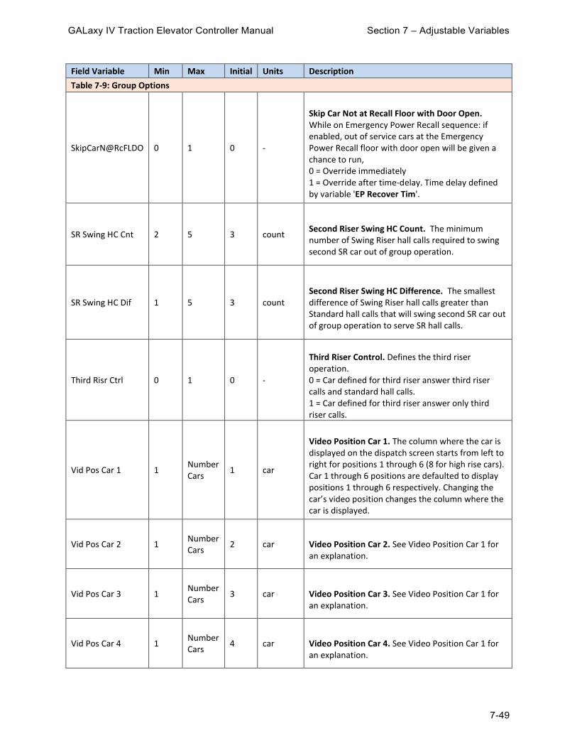
GALaxy IV Traction Elevator Controller Manual Section 7 – Adjustable Variables
7-49
Field Variable Min Max Initial Units Description
Table 7-9: Group Options
SkipCarN@RcFLDO 0 1 0 -
Skip Car Not at Recall Floor with Door Open. While on Emergency Power Recall sequence: if enabled, out of service cars at the Emergency Power Recall floor with door open will be given a chance to run, 0 = Override immediately 1 = Override after time-delay. Time delay defined by variable 'EP Recover Tim'.
SR Swing HC Cnt 2 5 3 count
Second Riser Swing HC Count. The minimum number of Swing Riser hall calls required to swing second SR car out of group operation.
SR Swing HC Dif 1 5 3 count
Second Riser Swing HC Difference. The smallest difference of Swing Riser hall calls greater than Standard hall calls that will swing second SR car out of group operation to serve SR hall calls.
Third Risr Ctrl 0 1 0 -
Third Riser Control. Defines the third riser operation. 0 = Car defined for third riser answer third riser calls and standard hall calls. 1 = Car defined for third riser answer only third riser calls.
Vid Pos Car 1 1 Number Cars
1 car
Video Position Car 1. The column where the car is displayed on the dispatch screen starts from left to right for positions 1 through 6 (8 for high rise cars). Car 1 through 6 positions are defaulted to display positions 1 through 6 respectively. Changing the car’s video position changes the column where the car is displayed.
Vid Pos Car 2 1 Number Cars
2 car Video Position Car 2. See Video Position Car 1 for an explanation.
Vid Pos Car 3 1 Number Cars
3 car Video Position Car 3. See Video Position Car 1 for an explanation.
Vid Pos Car 4 1 Number Cars
4 car Video Position Car 4. See Video Position Car 1 for an explanation.

GALaxy IV Traction Elevator Controller Manual Section 7 – Adjustable Variables
7-50
Field Variable Min Max Initial Units Description
Table 7-9: Group Options
Vid Pos Car 5 1 Number Cars
5 car Video Position Car 5. See Video Position Car 1 for an explanation.
Vid Pos Car 6 1 Number Cars
6 car Video Position Car 6. See Video Position Car 1 for an explanation.
Vid Pos Car 7 1 Number Cars
7 car Video Position Car 7. See Video Position Car 1 for an explanation.
Vid Pos Car 8 1 Number Cars
8 car Video Position Car 8. See Video Position Car 1 for an explanation.
Vip Button Loc 0 2 0 -
VIP Button Location. 0 = VIP on vip I/O board 1 = VIP on HCB I/O board 2 = VIP on IR I/O
VIP Operation 0 3 0 -
VIP (Priority Call) Operation. +1 = Cancel hall call if no cars available for VIP call. +2 = Cancel car call upon initiation of being selected as the VIP car.
VIP Sel IR Car 0 1 0 - VIP Selection Over IR Car. Enables VIP operation to select a car that is on IR service.
X-Assign Cars 0 Number Cars
0 car
Cross Assignment Cars. Number of cars in the old group to assign calls using cross assignment system.

GALaxy IV Traction Elevator Controller Manual Section 7 – Adjustable Variables
7-51
7.1.10 CC & COP Lights Submenu
Field Variable Min Max Initial Units Description
Table 7-10: CC & COP Lights
Backlight Lt 0 63 0 color
Enable Backlight Output Lights for RGB style output lights in COP Bit0: Fire, Bit1: Medical, Bit2: Emergency, Bit3: OTS, Bit4: Att Up/Dn Light, Bit5: Non-CC
CC AttDn Blue 0 100 0 % Car Call Button Attendant Dn Light Blue Intensity
CC AttDn Bright 0 100 100 % Car Call Button Attendant Dn Light Brightness
CC AttDn Color 0 15 0 color
Car Call Button Attendant Dn Light Color: 0 Based on parameters 1 Red 2 Orange 3 Yellow 4 Chartreuse 5 Green 6 Aquamarine 7 Cyan 8 Azure 9 Blue 10 Violet 11 Magenta 12 Rose 13 Rose White 14 Warm White 15 Cool White
CC AttDn Green 0 100 0 % Car Call Button Attendant Dn Light Green Intensity
CC AttDn Red 0 100 100 % Car Call Button Attendant Dn Light Red Intensity
CC AttUp Blue 0 100 0 % Car Call Button Attendant Up Light Blue Intensity
CC AttUp Bright 0 100 100 % Car Call Button Attendant Up Light Brightness

GALaxy IV Traction Elevator Controller Manual Section 7 – Adjustable Variables
7-52
Field Variable Min Max Initial Units Description
Table 7-10: CC & COP Lights
CC AttUp Color 0 15 0 color
Car Call Button Attendant Up Light Color: 0 Based on parameters 1 Red 2 Orange 3 Yellow 4 Chartreuse 5 Green 6 Aquamarine 7 Cyan 8 Azure 9 Blue 10 Violet 11 Magenta 12 Rose 13 Rose White 14 Warm White 15 Cool White
CC AttUp Green 0 100 100 % Car Call Button Attendant Up Light Green Intensity
CC AttUp Red 0 100 0 % Car Call Button Attendant Up Light Red Intensity
CC Light Ctl 0 3 0
Flashing Car Call Lights options. +1 = Flash Car Call Security +2= Flash Attendant Annunciator Sequence
CC Off Blue 0 100 50 % Car Call Off Blue Intensity
CC Off Bright 0 100 20 % Car Call Output Off Brightness for LED
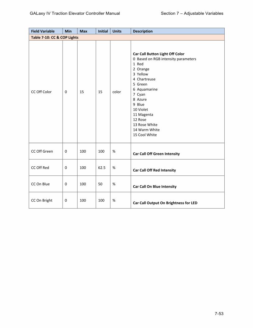
GALaxy IV Traction Elevator Controller Manual Section 7 – Adjustable Variables
7-53
Field Variable Min Max Initial Units Description
Table 7-10: CC & COP Lights
CC Off Color 0 15 15 color
Car Call Button Light Off Color 0 Based on RGB intensity parameters 1 Red 2 Orange 3 Yellow 4 Chartreuse 5 Green 6 Aquamarine 7 Cyan 8 Azure 9 Blue 10 Violet 11 Magenta 12 Rose 13 Rose White 14 Warm White 15 Cool White
CC Off Green 0 100 100 % Car Call Off Green Intensity
CC Off Red 0 100 62.5 % Car Call Off Red Intensity
CC On Blue 0 100 50 % Car Call On Blue Intensity
CC On Bright 0 100 100 % Car Call Output On Brightness for LED

GALaxy IV Traction Elevator Controller Manual Section 7 – Adjustable Variables
7-54
Field Variable Min Max Initial Units Description
Table 7-10: CC & COP Lights
CC On Color 0 15 15 color
Car Call Button Light On Color 0 Based on RGB intensity parameters 1 Red 2 Orange 3 Yellow 4 Chartreuse 5 Green 6 Aquamarine 7 Cyan 8 Azure 9 Blue 10 Violet 11 Magenta 12 Rose 13 Rose White 14 Warm White 15 Cool White
CC On Green 0 100 100 % Car Call On Green Intensity
CC On Red 0 100 62.5 % Car Call On Red Intensity
CC Sec Blue 0 100 100 % Car Call Security Light Blue Intensity
CC Sec Bright 0 100 100 % Car Call Security Light Brightness

GALaxy IV Traction Elevator Controller Manual Section 7 – Adjustable Variables
7-55
Field Variable Min Max Initial Units Description
Table 7-10: CC & COP Lights
CC Sec Color 0 15 15 color
Car Call Button Security Color 0 Based on RGB intensity parameters 1 Red 2 Orange 3 Yellow 4 Chartreuse 5 Green 6 Aquamarine 7 Cyan 8 Azure 9 Blue 10 Violet 11 Magenta 12 Rose 13 Rose White 14 Warm White 15 Cool White
CC Sec Green 0 100 0 % Car Call Security Light Green intensity
CC Sec Red 0 100 100 % Car Call Security Light Red Intensity
Emer Lt Blue 0 100 0 % Emergency Light Blue Intensity
Emer Lt Bright 0 100 100 % Emergency Light Brightness

GALaxy IV Traction Elevator Controller Manual Section 7 – Adjustable Variables
7-56
Field Variable Min Max Initial Units Description
Table 7-10: CC & COP Lights
Emer Lt Color 0 15 0 color
Emergency Light Color 0 Based on parameters 1 Red 2 Orange 3 Yellow 4 Chartreuse 5 Green 6 Aquamarine 7 Cyan 8 Azure 9 Blue 10 Violet 11 Magenta 12 Rose 13 Rose White 14 Warm White 15 Cool White
Emer Lt Green 0 100 100 % Emergency Light Green Intensity
Emer Lt Red 0 100 75 % Emergency Light Red Intensity
Fire Lt Blue 0 100 50 % Fire Light Blue Intensity
Fire Lt Bright 0 100 100 % Fire light Brightness

GALaxy IV Traction Elevator Controller Manual Section 7 – Adjustable Variables
7-57
Field Variable Min Max Initial Units Description
Table 7-10: CC & COP Lights
Fire Lt Color 0 15 0 color
Fire Light Color: 0 Based on parameters 1 Red 2 Orange 3 Yellow 4 Chartreuse 5 Green 6 Aquamarine 7 Cyan 8 Azure 9 Blue 10 Violet 11 Magenta 12 Rose 13 Rose White 14 Warm White 15 Cool White
Fire Lt Green 0 100 100 % Fire Light Green Intensity
Fire Lt Red 0 100 62.5 % Fire Light Red Intensity
Med Lt Blue 0 100 100 % Medical Light Blue Intensity
Med Lt Bright 0 100 100 % Medical Light Brightness

GALaxy IV Traction Elevator Controller Manual Section 7 – Adjustable Variables
7-58
Field Variable Min Max Initial Units Description
Table 7-10: CC & COP Lights
Med Lt Color 0 15 0 color
Medical Light Color: 0 Based on parameters 1 Red 2 Orange 3 Yellow 4 Chartreuse 5 Green 6 Aquamarine 7 Cyan 8 Azure 9 Blue 10 Violet 11 Magenta 12 Rose 13 Rose White 14 Warm White 15 Cool White
Med Lt Green 0 100 0 % Medical Light Green Intensity
Med Lt Red 0 100 0 % Medical Light Red Intensity
OTS Lt Blue 0 100 0 % Out of Service Light Blue Intensity
OTS Lt Bright 0 100 100 % Out of Service Light Brightness

GALaxy IV Traction Elevator Controller Manual Section 7 – Adjustable Variables
7-59
Field Variable Min Max Initial Units Description
Table 7-10: CC & COP Lights
OTS Lt Color 0 15 0 color
Out of Service Light Color 0 Based on parameters 1 Red 2 Orange 3 Yellow 4 Chartreuse 5 Green 6 Aquamarine 7 Cyan 8 Azure 9 Blue 10 Violet 11 Magenta 12 Rose 13 Rose White 14 Warm White 15 Cool White
OTS Lt Green 0 100 40 % Out of Service Light Green Intensity
OTS Lt Red 0 100 100 % Out of Service light red intensity
7.1.11 HC & IR Call Lights Submenu
Field Variable Min Max Initial Units Description
Table 7-11: HC & IR Call Lights
HC Off Bright 0 100 20 %
Hall Call Light Off Brightness. Select the brightness for LED hall call button when button is NOT pressed. Used only with GAL serial hall button fixtures.
HC On Brght 0 100 100 %
Hall Call Light On Brightness for LED Hall Call Buttons. Used only with GAL serial hall button fixtures.
HCDn Off Blue 0 100 50 % Hall Call Light Off Blue Intensity. Used only with GAL serial hall button fixtures.
HCDn Off Brght 0 100 20 %
Hall Call Light Off Brightness for LED Hall Call Buttons. Used only with GAL serial hall button fixtures.

GALaxy IV Traction Elevator Controller Manual Section 7 – Adjustable Variables
7-60
Field Variable Min Max Initial Units Description
Table 7-11: HC & IR Call Lights
HCDn Off Color 0 15 15 color
Hall Down Call Off Color. Select what color LED to illuminate on hall call button when button is NOT pressed. Used only with GAL serial hall button fixtures. 0 Based on parameters 1 Red 2 Orange 3 Yellow 4 Chartreuse 5 Green 6 Aquamarine 7 Cyan 8 Azure 9 Blue 10 Violet 11 Magenta 12 Rose 13 Rose White 14 Warm White 15 Cool White
HCDn Off Green 0 100 100 % Hall Call Light Off Green Intensity. Used only with GAL serial hall button fixtures.
HCDn Off Red 0 100 62.5 % Hall Call Light Off Red Intensity. Used only with GAL serial hall button fixtures.
HCDn On Blue 0 100 50 % Hall Call Light On Blue Intensity. Used only with GAL serial hall button fixtures.
HCDn On Bright 0 100 100 %
Hall Call Light On Brightness for LED Hall Call Buttons. Used only with GAL serial hall button fixtures.

GALaxy IV Traction Elevator Controller Manual Section 7 – Adjustable Variables
7-61
Field Variable Min Max Initial Units Description
Table 7-11: HC & IR Call Lights
HCDn On Color 0 15 15 color
Hall Call Down On Light Color. Select what color LED to illuminate on hall call button when button is pressed. Used only with GAL serial hall button fixtures. 0 Based on parameters 1 Red 2 Orange 3 Yellow 4 Chartreuse 5 Green 6 Aquamarine 7 Cyan 8 Azure 9 Blue 10 Violet 11 Magenta 12 Rose 13 Rose White 14 Warm White 15 Cool White
HCDn On Green 0 100 100 % Hall Call Light On Green Intensity. Used only with GAL serial hall button fixtures.
HCDn On Red 0 100 62.5 % Hall Call Light On Red Intensity. Used only with GAL serial hall button fixtures.
HCUp Off Blue 0 100 50 % Hall Call Up Light Off Blue Intensity.
HCUp Off Brght 0 100 20 % Hall Call Output Off Brightness for LED (higher number is brighter)

GALaxy IV Traction Elevator Controller Manual Section 7 – Adjustable Variables
7-62
Field Variable Min Max Initial Units Description
Table 7-11: HC & IR Call Lights
HCUp Off Color 0 15 15
Hall Call Button Up Light Off Color 0 Based on RGB intensity parameters 1 Red 2 Orange 3 Yellow 4 Chartreuse 5 Green 6 Aquamarine 7 Cyan 8 Azure 9 Blue 10 Violet 11 Magenta 12 Rose 13 Rose White 14 Warm White 15 Cool White
HCUp Off Green 0 100 100 % Hall Call Up Light Off Green Intensity
HCUp Off Red 0 100 62.5 % Hall Call Up Light Off Red Intensity
HCUp On Blue 0 100 50 % Hall Call UP Light On Blue Intensity
HCUp On Bright 0 100 0 % Hall Call Output Up On Brightness for LED (higher number is brighter)

GALaxy IV Traction Elevator Controller Manual Section 7 – Adjustable Variables
7-63
Field Variable Min Max Initial Units Description
Table 7-11: HC & IR Call Lights
HCUp On Color 0 15 15 color
Hall Call Button Up Light On Color 0 Based on RGB intensity parameters 1 Red 2 Orange 3 Yellow 4 Chartreuse 5 Green 6 Aquamarine 7 Cyan 8 Azure 9 Blue 10 Violet 11 Magenta 12 Rose 13 Rose White 14 Warm White 15 Cool White
HCUp On Green 0 100 100 % Hall Call Up Light On Green Intensity
HCUp On Red 0 100 62.5 % Hall Call Up Light On Red Intensity
IR Color Ctrl 0 1 0 -
IR light color control: 0 = IR Color 1 = HC Color until IR activated
IRDn Off Blue 0 100 50 % Hall Call IR Dn Light Off Blue Intensity
IRDn Off Brght 0 100 20 % Hall Call IR Dn Light Off Brightness

GALaxy IV Traction Elevator Controller Manual Section 7 – Adjustable Variables
7-64
Field Variable Min Max Initial Units Description
Table 7-11: HC & IR Call Lights
IRDn Off Color 0 15 15 color
Hall Call IR Dn Light Off Color 0 Based on parameters 1 Red 2 Orange 3 Yellow 4 Chartreuse 5 Green 6 Aquamarine 7 Cyan 8 Azure 9 Blue 10 Violet 11 Magenta 12 Rose 13 Rose White 14 Warm White 15 Cool White
IRDn Off Green 0 100 100 % Hall Call IR Dn Light Off Green Intensity
IRDn Off Red 0 100 62.5 % Hall Call IR Dn Light Off Red Intensity
IRDn On Blue 0 100 50 % Hall Call IR Dn Light On Blue Intensity
IRDn On Bright 0 100 20 % Hall Call IR Dn Light On Brightness

GALaxy IV Traction Elevator Controller Manual Section 7 – Adjustable Variables
7-65
Field Variable Min Max Initial Units Description
Table 7-11: HC & IR Call Lights
IRDn On Color 0 15 15 color
Hall Call IR Dn Light On Color 0 Based on parameters 1 Red 2 Orange 3 Yellow 4 Chartreuse 5 Green 6 Aquamarine 7 Cyan 8 Azure 9 Blue 10 Violet 11 Magenta 12 Rose 13 Rose White 14 Warm White 15 Cool White
IRDn On Green 0 100 100 % Hall Call IR Dn Light On Green Intensity
IRDn On Red 0 100 62.5 % Hall Call IR Dn Light On Red Intensity
IRUp Off Blue 0 100 50 % Hall Call IR Up Light Off Blue Intensity
IRUp Off Brght 0 100 100 % Hall Call IR Up Light Off Brightness

GALaxy IV Traction Elevator Controller Manual Section 7 – Adjustable Variables
7-66
Field Variable Min Max Initial Units Description
Table 7-11: HC & IR Call Lights
IRUp Off Color 0 15 15 color
Hall Call IR Up Light Off Color 0 Based on parameters 1 Red 2 Orange 3 Yellow 4 Chartreuse 5 Green 6 Aquamarine 7 Cyan 8 Azure 9 Blue 10 Violet 11 Magenta 12 Rose 13 Rose White 14 Warm White 15 Cool White
IRUp Off Green 0 100 100 % Hall Call IR Up Light Off Green Intensity
IRUp Off Red 0 100 62.5 % Hall Call IR Up Light Off Red Intensity
IRUp On Blue 0 100 50 % Hall Call IR Up On Blue Intensity
IRUp On Bright 0 100 100 % Hall Call IR Up On Brightness

GALaxy IV Traction Elevator Controller Manual Section 7 – Adjustable Variables
7-67
Field Variable Min Max Initial Units Description
Table 7-11: HC & IR Call Lights
IRUp On Color 0 15 15 color
Hall Call IR Up On Color 0 Based on parameters 1 Red 2 Orange 3 Yellow 4 Chartreuse 5 Green 6 Aquamarine 7 Cyan 8 Azure 9 Blue 10 Violet 11 Magenta 12 Rose 13 Rose White 14 Warm White 15 Cool White
IRUp On Green 0 100 100 % Hall Call IR Up On Green Intensity
IRUp On Red 0 100 62.5 % Hall Call IR Up On Red Intensity
7.1.12 CB, VIP HSec Hall Lights Submenu
Field Variable Min Max Initial Units Description
Table 7-12: CB, VIP HSec Call Lights
CB Off Blue 0 100 100 % Hall Call CB Light Off Blue Intensity
CB Off Bright 0 100 20 % Hall Call CB Light Off Brightness

GALaxy IV Traction Elevator Controller Manual Section 7 – Adjustable Variables
7-68
Field Variable Min Max Initial Units Description
Table 7-12: CB, VIP HSec Call Lights
CB Off Color 0 15 0 color
Hall Call CB Light Off Color 0 Based on parameters 1 Red 2 Orange 3 Yellow 4 Chartreuse 5 Green 6 Aquamarine 7 Cyan 8 Azure 9 Blue 10 Violet 11 Magenta 12 Rose 13 Rose White 14 Warm White 15 Cool White
CB Off Green 0 100 0 % Hall Call CB Light Off Green Intensity
CB Off Red 0 100 0 % Hall Call CB Light Off Red Intensity
CB On Blue 0 100 100 % Hall Call CB Light On Blue Intensity
CB On Bright 0 100 100 % Hall Call CB Light On Brightness

GALaxy IV Traction Elevator Controller Manual Section 7 – Adjustable Variables
7-69
Field Variable Min Max Initial Units Description
Table 7-12: CB, VIP HSec Call Lights
CB On Color 0 15 0 color
Hall Call CB Light On Color: 0 Based on parameters 1 Red 2 Orange 3 Yellow 4 Chartreuse 5 Green 6 Aquamarine 7 Cyan 8 Azure 9 Blue 10 Violet 11 Magenta 12 Rose 13 Rose White 14 Warm White 15 Cool White
CB On Green 0 100 0 % Hall Call CB Light On Green Intensity
CB On Red 0 100 0 % Hall Call CB Light On Red Intensity
HC Sec Blue 0 100 100 % Hall Call Light Blue Intensity When on Security. Used only with GAL serial hall button fixtures.
HC Sec Bright 0 100 100 % Hall Call Security Brightness for Secured Floors

GALaxy IV Traction Elevator Controller Manual Section 7 – Adjustable Variables
7-70
Field Variable Min Max Initial Units Description
Table 7-12: CB, VIP HSec Call Lights
HC Sec Color 0 15 15 color
Hall Call Security Color to illuminate the hall buttons when the system is on security. Used only with GAL serial hall button fixtures. 0 Based on parameters 1 Red 2 Orange 3 Yellow 4 Chartreuse 5 Green 6 Aquamarine 7 Cyan 8 Azure 9 Blue 10 Violet 11 Magenta 12 Rose 13 Rose White 14 Warm White 15 Cool White
HC Sec Ctl 0 7 0 -
Hall Call Button Security Light. +1 = Invert security +2 = Flash security +4 = Master Security Enabled
HC Sec Green 0 100 0 % Hall Call Light Green Intensity When on Security. Used only with GAL serial hall button fixtures.
HC Sec Red 0 100 100 % Hall Call Light Red Intensity When on Security. Used only with GAL serial hall button fixtures.
Vip Off Blue 0 100 0 % Hall Call Vip Light Off Blue Intensity
Vip Off Bright 0 100 20 % Hall Call Vip Light Off Brightness

GALaxy IV Traction Elevator Controller Manual Section 7 – Adjustable Variables
7-71
Field Variable Min Max Initial Units Description
Table 7-12: CB, VIP HSec Call Lights
Vip Off Color 0 15 0 color
Hall Call Vip Light Off Color 0 Based on parameters 1 Red 2 Orange 3 Yellow 4 Chartreuse 5 Green 6 Aquamarine 7 Cyan 8 Azure 9 Blue 10 Violet 11 Magenta 12 Rose 13 Rose White 14 Warm White 15 Cool White
Vip Off Green 0 100 40 % Hall Call Vip Light Off Green Intensity
Vip Off Red 0 100 100 % Hall Call Vip Light Off Red Intensity
Vip On Blue 0 100 0 % Hall Call Vip Light On Blue Intensity
Vip On Bright 0 100 100 % Hall Call Vip Light On Brightness

GALaxy IV Traction Elevator Controller Manual Section 7 – Adjustable Variables
7-72
Field Variable Min Max Initial Units Description
Table 7-12: CB, VIP HSec Call Lights
Vip On Color 0 15 0 color
Hall Call Vip Light On Color 0 Based on parameters 1 Red 2 Orange 3 Yellow 4 Chartreuse 5 Green 6 Aquamarine 7 Cyan 8 Azure 9 Blue 10 Violet 11 Magenta 12 Rose 13 Rose White 14 Warm White 15 Cool White
Vip On Green 0 100 40 % Hall Call Vip Light On Green Intensity
Vip On Red 0 100 100 % Hall Call Vip Light On Red Intensity
7.1.13 System Options Submenu
Field Variable Min Max Initial Units Description
Table 7-13: System Options
485 Port Sel 0 1 0 -
485 Port Sel. Selects the operation of 485 port. 485 com port select: 0 = IGEP if enabled 1 = EX-51 Hall Lantern
Auto Fault Dpy 0 1 0 -
Automatic Fault Display. Enable to automatically display a fault on the LCD screen. 0 = Disabled 1 = Enabled

GALaxy IV Traction Elevator Controller Manual Section 7 – Adjustable Variables
7-73
Field Variable Min Max Initial Units Description
Table 7-13: System Options
Auto WIFI Setup 0 1 1 -
Automatic WiFi Setup. Turns on option to have controller automatically update Wi-Fi board for Galileo if connection is lost. 0 = Disabled 1 = Enabled
CAN Baud Rate 0 1 0 bps
CAN Baud Rate. Set to zero and do not change. Special jobs utilize a different baud rate for CAN Bus. All devices need to be reconfigured for new rate. CAN Baud Rate, 0 = 115.2K 1 = 57.6K
CAN Sync Count 0 7 4 count
CAN Sync Count. Frequency to update CAN Bus devices. Units are 1/4 seconds. It sets Synchronization Count in 250 millisecond increments
COM 1 Baud Rate
0 9 6 bps
Com 1 User Interface Baud Rate. Selects the bit rate of the COM 1 serial port. 0 = 2400 bps 1 = 4800 bps 2 = 9600 bps 3 = 19200 bps 4 = 38400 bps 5 = 57600 bps 6 = 115200 bps 7 = 219254 bps 8 = 226562.5 bps 9 = 234375 bps
Com 1 Port Sel 0 7 6 -
Com 1 Port Select. Selects the operation of COM 1 port. 0 = Comm Diag 1 = Comm Debug 2 = Galcom 3 = DL20 4 = Galcom Wireless 5 = Galcom Ethernet 6 = Galcom Wireless Flow Control 7 = Galcom Ethernet Flow Control

GALaxy IV Traction Elevator Controller Manual Section 7 – Adjustable Variables
7-74
Field Variable Min Max Initial Units Description
Table 7-13: System Options
Com 2 Baud Rate 0 9 3 bps
COM 2 User Interface Baud Rate. Selects the bit rate of the COM 2 serial port. 0 = 2400 bps 1 = 4800 bps 2 = 9600 bps 3 = 19200 bps 4 = 38400 bps 5 = 57600 bps 6 = 115200 bps 7 = 219254 bps 8 = 226562.5 bps 9 = 234375 bps
Com 2 Port Sel 0 7 0 -
Com 2 Port Select. Selects the operation of COM 2 port. 0 = Comm Diag 1 = Comm Debug 2 = Galcom 3 = DL20 4 = Galcom Wireless 5 = Galcom Ethernet 6 = Galcom Wireless Flow Control 7 = Galcom Ethernet Flow Control
CPU Tim Output 0 7 0 -
CPU Timing Output. The CPU has three test point pins that outputs timing signals depending upon the setting of this parameter. These are 5 Volt signals that can be monitored by an oscilloscope. 0 = Z6 LED 1 second pulse 1 = Inctime 2 = GrpIO 4 = 10 msec
Drive Baud Rate 0 3 0 bps
Drive Baud Rate. 0 = 19200 (HPV-900, DSD-412, HPV-600 and Quattro Drives). 1 = 38400 2 = 57600 (KEB Drives) 3 = 11500
Drive Modbus 0 5 0 -
Drive Modbus Protocol. 0-5 = N1, N2, E1, E2, O1, O2 (Always 8 data bits, parity, stop bits). Used for Delta drive.

GALaxy IV Traction Elevator Controller Manual Section 7 – Adjustable Variables
7-75
Field Variable Min Max Initial Units Description
Table 7-13: System Options
Drv Update Rate 0 2 0 -
Drive Command Update Rate. Rate at which commands are sent to the drive. 0 = 10 msec (HPV-900, DSD-412, HPV-600 and Quattro Drives), 1 = 15 msec 2 = 20 msec
EE Memory Type 0 1 0 -
EE Memory Type. Selects the type of memory chip used with the TS-5600 CPU. 0 = STK16C88 1 = STK16C68. Not used with GALX-1100AN CPU board
Encoder Baud 0 1 0 bps
Encoder CAN Open Baud Rate. 0 = 250K 1 = 125K bits per second.
Encoder Intrvl 1 5 3 -
Encoder Interval. Defines the intervals for sampling the encoder reads for calculating speed. Default value of 3 will work on most jobs. For cars with distance feedback from pulses on a tape selector, a value of 5 will work best.
Encoder NodeID 1 127 63 -
Encoder Node ID. Selects the Node ID for the CAN Open encoder. Must be set to for the specific vendor’s encoder (also see encoder type): Turck = 63 Dynapar = 1 Wachendorff = 127 Not used when Encoder Type = 4 (Tape Selector)
Encoder Sample 2 10 10 -
Encoder Samples. Determines the samples used to calculate the speed from the encoder. Default values should work in all jobs.
Encoder Type 0 4 0 -
Encoder Type. Selects type of encoder feedback used. 0 = Based on CONS file setting 1 = Turck CAN Open Encoder 2 = Dynapar CAN Open Encoder 3 = Wachendorff CAN Open Encoder 4 = Selector Tape

GALaxy IV Traction Elevator Controller Manual Section 7 – Adjustable Variables
7-76
Field Variable Min Max Initial Units Description
Table 7-13: System Options
Exclusion FLT 1 0 Max Faults
0 fault
Exclusion fault 1: Set to fault code number. This prevents faults from being recorded in the fault log. It should only be set for nuisance and noncritical faults. Controller still goes through all the logic for each fault code except, a call is not recorded in the fault log.
Exclusion FLT 2 0 Max Faults
0 fault
Exclusion fault 2: Set to fault code number. This prevents faults from being recorded in the fault log. It should only be set for nuisance and noncritical faults. Controller still goes through all the logic for each fault code except, a call is not recorded in the fault log.
Exclusion FLT 3 0 Max Faults
0 fault
Exclusion fault 3: Set to fault code number. This prevents faults from being recorded in the fault log. It should only be set for nuisance and noncritical faults. Controller still goes through all the logic for each fault code except, a call is not recorded in the fault log.
Exclusion FLT 4 0 Max Faults
0 fault
Exclusion fault 4: Set to fault code number. This prevents faults from being recorded in the fault log. It should only be set for nuisance and noncritical faults. Controller still goes through all the logic for each fault code except, a call is not recorded in the fault log.
Exclusion FLT 5 0 Max Faults
0 fault
Exclusion fault 5: Set to fault code number. This prevents faults from being recorded in the fault log. It should only be set for nuisance and noncritical faults. Controller still goes through all the logic for each fault code except, a call is not recorded in the fault log.
Exclusion FLT 6 0 Max Faults
0 fault
Exclusion fault 6: Set to fault code number. This prevents faults from being recorded in the fault log. It should only be set for nuisance and noncritical faults. Controller still goes through all the logic for each fault code except, a call is not recorded in the fault log.
Galileo Group # 1 24 1 - Galileo Group Number. Set group number to assign unique IP addresses on auto ethernet setup.

GALaxy IV Traction Elevator Controller Manual Section 7 – Adjustable Variables
7-77
Field Variable Min Max Initial Units Description
Table 7-13: System Options
GMON Intrvl Tim 0 10 0.2 Sec
GAL Monitor Interval Timer. Controls the timer interval that data packets are transmitted. When zero, data is not transmitted on a time interval.
GMON Pkt Cntrl 0 7 0 -
GAL Monitor Serial Output Packet Control. This variable controls how the controller data is being packed and unpacked in the serial data.
GMON Upd Cntrl 0 3 0 - GAL Monitor Update Control. Controls how the packet data on the serial port is updated.
KEB Dpy Type 0 1 0 -
KEB Display Type. 0 = Standard Red LED Display 1 = LCD Display Power must be cycled for change in serial protocol.
Low Bat Cap Lev 0 101 50 %
For UPS Systems. This is the battery level at which the controller will fault out due to Low Battery Capacity.
Low Door Volt 0 600 198 Vrms
Low Door Voltage. Settings for Line Voltage Monitor Board. It sets the value of voltage for 'Door Low Voltage Fault' to be triggered.
Low Line Volt 0 600 198 Vrms
Low Line Voltage. Settings for Line Voltage Monitor Board. It sets the value of voltage for a 'Low Line Voltage Fault' to be triggered.
Password 0 9999 0 - Password Code to modify and adjust field variables.
PI Message Type 0 1 0 -
PI Message Type. When set advanced PI message is used (packet 125 instead of packet 25). 0 = Disable 1 = Enable
Pword Time-out 0 3200 300 sec Password Time-out. The amount of inactive time for the LCD to lock out the field variables.

GALaxy IV Traction Elevator Controller Manual Section 7 – Adjustable Variables
7-78
Field Variable Min Max Initial Units Description
Table 7-13: System Options
RS485 COM Baud 0 6 0 bps
RS485 COM Baud Rate. 0 = 2400 1 = 4800 2 = 9600 3 = 19.2K 4 = 38.4K 5 = 57.6K 6 = 115.2K bits per second
Safe Test Day 1 31 0 day Safety Test Day.
Safe Test Month 1 12 0 month Safety Test Month.
Safe Test Year 2000 2999 0 year Safety Test Year.
Service UPS 0 1 0 -
Service UPS mode. Turning this parameter ON disables UPS faults. It should only be used in Construction mode or while servicing the UPS.
UPS Baud Rate 0 3 2 bps
UPS Baud Rate: 0 = 2400 1 = 4800 2 = 9600 3 = 19200
Video Time out 0 3200 0 sec
Video Time-out. Turn off the machine room video after this timer expires This function is disabled when set to zero.
7.2 Safety Processor Adjustable Variables
Field Variable Min Max Initial Units Description
Table – 7-14: Safety Processor Adjustable Variables
2 Stop 0 1 0 -
2 Stop. Set to 1 if this car travels to only two landings. This parameter tells the Safety Processor that there are no middle door locks.

GALaxy IV Traction Elevator Controller Manual Section 7 – Adjustable Variables
7-79
Field Variable Min Max Initial Units Description
Table – 7-14: Safety Processor Adjustable Variables
Buffer Type 0 1 0 -
Buffer Type. This parameter is set to 1 when there is a reduced stroke buffer and enables the use of the ETU and ETD verification limits. This parameter must match the jumper setting for the PAL on the 1102 board AND the job configuration setting for reduced stroke buffer in the configuration file. If all three do not match, the car is not allowed to run.
CAN Baud Rate 0 1 0 bps
CAN Baud Rate. Set the baud rate for the CAN Bus. 0 =115.2K 1 = 57.6K
Comm Chk Dis 0 1 0 -
Communications Check. This parameter disables the CAN Bus communications check. This is variable allows a new Safety Processor Board to be used on older GALaxy I or II controllers that did not use CAN Bus communications. On GALaxy III controllers, the main CPU must have Can Bus communications.
Control Type 0 2 0 -
Control Type. Type of controller used. 0 = Hydro 1 = Traction Non‐Distance Feedback 2 = Traction Distance Feedback.
DT Count 0 10000 12 count
DT Count. Number of pulse counts after the DT limit is hit where the slowdown velocity check is made. Not used for GALaxy IV.
DTS Velocity 0 1600 200 fpm
Down Emergency Terminal Slowdown Velocity. Maximum velocity to hit the down terminal slowdown limit. Hitting the limit at a higher velocity will cause the Safety Processor board to shut the car down from a velocity error. For cars with speeds greater than 200 fpm.
Encoder Dir 0 1 0 - Encoder Direction. Determines if rotation for the up direction is clockwise or counterclockwise. 0 = CW1 = CCW
Encoder PPR 10 18000 2048 PPR Encoder PPR. Pulses Per Revolution of the Encoder.

GALaxy IV Traction Elevator Controller Manual Section 7 – Adjustable Variables
7-80
Field Variable Min Max Initial Units Description
Table – 7-14: Safety Processor Adjustable Variables
Encoder RPM 2.5 1800 105 RPM Encoder RPM. Revolutions Per Minute of the Encoder.
Encoder Type 0 4 0 -
Encoder Type. Type of feedback used by the Safety Processor to calculate the car’s velocity. 0 = Standard Tape 1 = Governor Encoder 2 = Encoded Tape 3 = Governor Pulses 4 = Incremental Encoder
ETS Down Vel 0 1600 200 fpm
Emergency Terminal Slowdown Down (ETD) Velocity. Maximum velocity to hit the down emergency terminal slowdown limit. Hitting the limit at a higher velocity than set by this parameter will cause the Safety Processor board to shut the car down from a velocity error. This limit is only used for Reduced Stroke Buffer.
ETS Setup Mode 0 2 0 -
ETS Setup Mode. 0 = Normal operation. The PAL parameters for ETS Up and Down Velocities cannot be modified. The ETSLD TST jumper on the 1102 board must match the ETS Setup Mode parameter for the car to run. 1 = PAL velocity setup mode. Parameters can be modified but the ETSLD TST jumper must also be placed on 1102 board. 2 = Power up debug mode.
ETS Up Vel 0 1600 200 fpm
Emergency Terminal Slowdown Up (ETU) Velocity. Maximum velocity to hit the up emergency terminal slowdown limit. Hitting the limit at a higher velocity than set by this parameter will cause the Safety Processor board to shut the car down from a velocity error. This limit is only used for Reduced Stroke Buffer.
Insp Velocity 0 200 140 fpm Inspection Velocity. Maximum velocity the car is allowed to run on inspection.
Leveling Vel 0 200 140 fpm Leveling Velocity. Maximum velocity the car is allowed to run while leveling with the door open.

GALaxy IV Traction Elevator Controller Manual Section 7 – Adjustable Variables
7-81
Field Variable Min Max Initial Units Description
Table – 7-14: Safety Processor Adjustable Variables
PAL ETS Dn Vel 0 1600 200 fpm
PAL ETSLD Dn Velocity. When the car is setup with reduced stroke buffer, if the car hits the Down ETS limit at a velocity greater than this value, the PAL will drop the RUN and Brake contactors to stop the car. See also Buffer Type). Note: This value is entered in fpm but is recalculated in pulses per 30 msec for the PAL device. The value may be changed to the nearest valid fpm after entered.
PAL ETS Up Vel 0 1600 200 fpm
PAL ETSLD Up Velocity. When the car is setup with reduced stroke buffer, if the car hits the Up ETS limit at a velocity greater than this value, the PAL will drop the RUN and Brake contactors to stop the car. See also Buffer Type). Note: This value is entered in fpm but is recalculated in pulses per 30 msec for the PAL device. The value may be changed to the nearest valid fpm after entered.
Pulse Flt Tmr 1 10 2 sec Pulse Count Fault Delay Time. Time delay to detect that the selector pulses have stopped.
Pulses Per Ft 1 3200 16 ppf Pulses Per Foot. Number of pulses in one foot.
Rear Doors 0 1 0 -
Rear Door. Indicates that the car has rear doors and the Safety Processor should verify the rear door gate and locks.
Short Floor 0 3 0 -
Short Floor. There is a short floor at the top or bottom landing. This parameter informs the safety processor that the car can be on a floor next to the terminal landing and have the terminal limits still active. 0 = None 1 = Top 2 = Bot 3 = Both
Soft Stop Time 1 10 1 sec
Soft Stop Timer. During a soft stop, the speed command is brought to zero, then the brake is dropped and finally the run outputs are turned off. This timer is used to keep the run outputs from timing out during a soft stop.

GALaxy IV Traction Elevator Controller Manual Section 7 – Adjustable Variables
7-82
Field Variable Min Max Initial Units Description
Table – 7-14: Safety Processor Adjustable Variables
Speed Chk Dis 0 1 0 -
Speed Check. If the car speed is 150 fpm or less, the Safety Processor Speed Check can be disabled from this variable. If the speed is greater than 150 fpm, the variable can still be set but the speed check is made anyway. The speed check function, verifies the car speed on inspection, in leveling with the door open and when the UT, DT, UTS and DTS limits are hit. The Safety Processor will also shut the car down if it stops getting pulses while the car is running (has an up or down run signal).
Top Speed 25 2000 200 fpm Top Speed or contract speed of the car.
UMotion Ck Dis 0 1 0 -
Unintended Motion Check 0 = Motion check 1 = Disable unintended motion check
UT Count 0 10000 12 count
UT Count. Number of pulse count after the UT limit is hit where the slowdown velocity check is made. Not used for GALaxy IV.
UTS Velocity 0 1600 200 fpm
Up Emergency Terminal Slowdown Velocity. Maximum velocity to hit the up terminal slowdown limit. Hitting the limit at a higher velocity will cause the Safety Processor board to shut the car down from a velocity error. For cars with speeds greater than 200 fpm.
Vel Flt Timer 0.1 0.5 0.18 sec Velocity Fault Delay Time. Time delay after a velocity fault to shut the car down.
7.3 NTS Processor Adjustable Variables
Field Variable Min Max Initial Units Description
Table 7-15: NTS Processor Adjustable Variables
CAN Baud Rate 0 1 0 bps
CAN Baud Rate. Set the baud rate for the CAN Bus. 0 = 115.2K 1 = 57.6K

GALaxy IV Traction Elevator Controller Manual Section 7 – Adjustable Variables
7-83
Field Variable Min Max Initial Units Description
Table 7-15: NTS Processor Adjustable Variables
Debug Mode 0 1 0 - Debug Mode
DT Velocity 0 1600 350 fpm
Down Terminal Slowdown Velocity. Maximum velocity to hit the down terminal slowdown limit. Hitting the limit at a higher velocity will cause the NTS Processor to drop the NTSD output to the drive. Removal of the signal will cause the drive to execute an emergency timed slowdown until the car reaches leveling speed. The car will stop when the terminal landing is reached.
DT1 Velocity 0 1600 450 fpm
Down Terminal 1-6 Slowdown Velocity. Maximum velocity to hit the down terminal slowdown limit. Hitting the limit at a higher velocity will cause the NTS Processor to drop the NTSD output to the drive. Removal of the signal will cause the drive to execute an emergency timed slowdown until the car reaches leveling speed. The car will stop when the terminal landing is reached.
DT2 Velocity 0 1600 550 fpm
Down Terminal 1-6 Slowdown Velocity. Maximum velocity to hit the down terminal slowdown limit. Hitting the limit at a higher velocity will cause the NTS Processor to drop the NTSD output to the drive. Removal of the signal will cause the drive to execute an emergency timed slowdown until the car reaches leveling speed. The car will stop when the terminal landing is reached.
DT3 Velocity 0 1600 650 fpm
Down Terminal 1-6 Slowdown Velocity. Maximum velocity to hit the down terminal slowdown limit. Hitting the limit at a higher velocity will cause the NTS Processor to drop the NTSD output to the drive. Removal of the signal will cause the drive to execute an emergency timed slowdown until the car reaches leveling speed. The car will stop when the terminal landing is reached.
DT4 Velocity 0 1600 750 fpm
Down Terminal 1-6 Slowdown Velocity. Maximum velocity to hit the down terminal slowdown limit. Hitting the limit at a higher velocity will cause the NTS Processor to drop the NTSD output to the drive. Removal of the signal will cause the drive to execute an emergency timed slowdown until the car reaches leveling speed. The car will stop when the terminal landing is reached.

GALaxy IV Traction Elevator Controller Manual Section 7 – Adjustable Variables
7-84
Field Variable Min Max Initial Units Description
Table 7-15: NTS Processor Adjustable Variables
DT5 Velocity 0 1600 850 fpm
Down Terminal 1-6 Slowdown Velocity. Maximum velocity to hit the down terminal slowdown limit. Hitting the limit at a higher velocity will cause the NTS Processor to drop the NTSD output to the drive. Removal of the signal will cause the drive to execute an emergency timed slowdown until the car reaches leveling speed. The car will stop when the terminal landing is reached.
DT6 Velocity 0 1600 950 fpm
Down Terminal 1-6 Slowdown Velocity. Maximum velocity to hit the down terminal slowdown limit. Hitting the limit at a higher velocity will cause the NTS Processor to drop the NTSD output to the drive. Removal of the signal will cause the drive to execute an emergency timed slowdown until the car reaches leveling speed. The car will stop when the terminal landing is reached.
Encoder PPR 10 20000 2048 PPR Encoder PPR. Pulses Per Revolution of the Encoder.
Encoder RPM 1 3000 1170 RPM Encoder RPM. Revolutions Per Minute of the Encoder.
Encoder Type 0 1 0 -
Encoder Type. Type of feedback used by the Safety Processor to calculate the car’s velocity. 0 = Tape 1 = Motor Encoder.
Top Speed 0 1600 350 fpm Top Speed or contract speed of the car.
UT Velocity 0 1600 350 fpm
Up Terminal Slowdown Velocity. Maximum velocity to hit the up terminal slowdown limit. Hitting the limit at a higher velocity will cause the NTS Processor to drop the NTSD output to the drive. Removal of the signal will cause the drive to execute an emergency timed slowdown until the car reaches leveling speed. The car will stop when the terminal landing is reached.

GALaxy IV Traction Elevator Controller Manual Section 7 – Adjustable Variables
7-85
Field Variable Min Max Initial Units Description
Table 7-15: NTS Processor Adjustable Variables
UT1 Velocity 0 1600 450 fpm
Up Terminal 1-6 Slowdown Velocity. Maximum velocity to hit the up terminal slowdown limit. Hitting the limit at a higher velocity will cause the NTS Processor to drop the NTSD output to the drive. Removal of the signal will cause the drive to execute an emergency timed slowdown until the car reaches leveling speed. The car will stop when the terminal landing is reached.
UT2 Velocity 0 1600 550 fpm
Up Terminal 1-6 Slowdown Velocity. Maximum velocity to hit the up terminal slowdown limit. Hitting the limit at a higher velocity will cause the NTS Processor to drop the NTSD output to the drive. Removal of the signal will cause the drive to execute an emergency timed slowdown until the car reaches leveling speed. The car will stop when the terminal landing is reached.
UT3 Velocity 0 1600 650 fpm
Up Terminal 1-6 Slowdown Velocity. Maximum velocity to hit the up terminal slowdown limit. Hitting the limit at a higher velocity will cause the NTS Processor to drop the NTSD output to the drive. Removal of the signal will cause the drive to execute an emergency timed slowdown until the car reaches leveling speed. The car will stop when the terminal landing is reached.
UT4 Velocity 0 1600 750 fpm
Up Terminal 1-6 Slowdown Velocity. Maximum velocity to hit the up terminal slowdown limit. Hitting the limit at a higher velocity will cause the NTS Processor to drop the NTSD output to the drive. Removal of the signal will cause the drive to execute an emergency timed slowdown until the car reaches leveling speed. The car will stop when the terminal landing is reached.
UT5 Velocity 0 1600 850 fpm
Up Terminal 1-6 Slowdown Velocity. Maximum velocity to hit the up terminal slowdown limit. Hitting the limit at a higher velocity will cause the NTS Processor to drop the NTSD output to the drive. Removal of the signal will cause the drive to execute an emergency timed slowdown until the car reaches leveling speed. The car will stop when the terminal landing is reached.
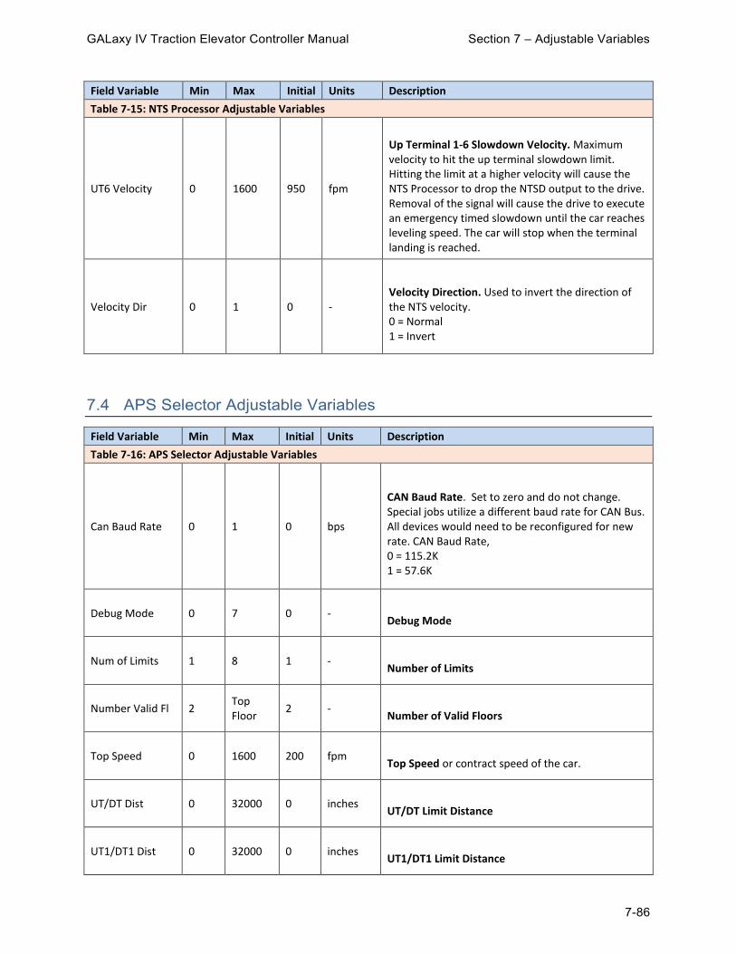
GALaxy IV Traction Elevator Controller Manual Section 7 – Adjustable Variables
7-86
Field Variable Min Max Initial Units Description
Table 7-15: NTS Processor Adjustable Variables
UT6 Velocity 0 1600 950 fpm
Up Terminal 1-6 Slowdown Velocity. Maximum velocity to hit the up terminal slowdown limit. Hitting the limit at a higher velocity will cause the NTS Processor to drop the NTSD output to the drive. Removal of the signal will cause the drive to execute an emergency timed slowdown until the car reaches leveling speed. The car will stop when the terminal landing is reached.
Velocity Dir 0 1 0 -
Velocity Direction. Used to invert the direction of the NTS velocity. 0 = Normal 1 = Invert
7.4 APS Selector Adjustable Variables
Field Variable Min Max Initial Units Description
Table 7-16: APS Selector Adjustable Variables
Can Baud Rate 0 1 0 bps
CAN Baud Rate. Set to zero and do not change. Special jobs utilize a different baud rate for CAN Bus. All devices would need to be reconfigured for new rate. CAN Baud Rate, 0 = 115.2K 1 = 57.6K
Debug Mode 0 7 0 - Debug Mode
Num of Limits 1 8 1 - Number of Limits
Number Valid Fl 2 Top Floor
2 - Number of Valid Floors
Top Speed 0 1600 200 fpm Top Speed or contract speed of the car.
UT/DT Dist 0 32000 0 inches UT/DT Limit Distance
UT1/DT1 Dist 0 32000 0 inches UT1/DT1 Limit Distance

GALaxy IV Traction Elevator Controller Manual Section 7 – Adjustable Variables
7-87
Field Variable Min Max Initial Units Description
Table 7-16: APS Selector Adjustable Variables
UT2/DT2 Dist 0 32000 0 inches UT2/DT2 Limit Distance
UT3/DT3 Dist 0 32000 0 inches UT3/DT3 Limit Distance
UT4/DT4 Dist 0 32000 0 inches UT4/DT4 Limit Distance
UT5/DT5 Dist 0 32000 0 inches UT5/DT5 Limit Distance
UT6/DT6 Dist 0 32000 0 inches UT6/DT6 Limit Distance
Table 7-17: Velocity Slowdown Table
FPM UT/ DT UT1/ DT1 UT2/ DT2 UT3/ DT3
50 5”
75 9”
100 12”
150 21”
200 30”
250 45”
300 25” 50”
350 33” 65”
400 41” 83”
450 51” 102”
500 56” 113”
600 52” 105” 157”
700 70” 140” 209”
800 67” 135” 202” 269”
900 77” 153” 230” 306”

GALaxy IV Traction Elevator Controller Manual Section 8 – Appendix A
8-1
Section 8 – Appendix A
Every safety precaution, whether or not specifically stated in this document, must be implemented when installing, adjusting, or servicing elevator equipment. All safety precautions must be followed to ensure the safety of elevator personnel and the general public. The test procedures outlined in this Appendix provide a guide for elevator personnel to perform the specific tests in this Appendix. These test procedures are not intended to override or circumvent any procedure or test that is mandated by the applicable codes and the Authority Having Jurisdiction.
All temporary connections must be removed before placing the elevator in service. If there are any questions in regard to the procedures for performing these tests with a GALaxy IV controller, please call GAL Manufacturing toll free at 1-(877) 425-7778 for free technical assistance.
8.1 Testing Precheck
Before attempting any tests, you must make sure that the following velocities all match while on inspection: Dmd Vel - CPU Demand Velocity Enc Vel - Encoder Velocity Drv Vel - Drive Velocity SPB Vel - Safety Processor Velocity NTS Vel - NTS Processor Velocity These velocities can be monitored at “Elevator Status”->Enter->Scroll Up or Down until you find each of the following: DMD, VEL, SPB VEL and NTS VEL. The Drive Velocity can be monitored in the Trace I/O Screen if you have a monitor or in drive parameter DG07. It is useful to confirm the velocity readings by using a handheld tachometer on the machine. The encoder pulses must also be verified. On the same screen where you see DMD & VEL (above) you will also see “DP=”, this number should increment as the car goes up and should decrement as the car goes down. If the “DP” count does not increment and decrement properly, complete the procedures in section 3.3.3, “Verify the Encoder Direction for the Main CPU”.

GALaxy IV Traction Elevator Controller Manual Section 8 – Appendix A
8-2
8.2 Inertia Learn (KEB Drive)
1) The car must be properly balanced, or the Inertia Learn will not be accurate. 2) Set LL10 in the drive to “Start” and follow the prompts. This will also activate Feed Forward
Torque Control (FFTC). 3) Make four runs up and down with the car and the drive will enter the learned values into LC42 &
LC43. 4) After the Inertia learn, it may be necessary to adjust LC42 (Feed Forward Torque Command
Filter). A higher value of LC42 can help smooth out vibrations if they are present. However, if the value is too high, it can introduce a delayed response.
5) LC43 (Feed Forward Torque Command Gain) can also be adjusted after the Inertia learn is completed. Higher values give more response, and lower values reduce the response. Try to make only small changes to this parameter.
8.3 Learn Limit Velocities
1) Go to “Elevator Setup -> Learn Limit Velocities” and follow the prompts. 2) Be sure to press “Enter” when asked to Preset Limit Velocities, this will set all limits to contract
speed before learning the limits. Failure to do so may prevent the limits from being learned properly.
3) After the limits are learned please verify that they were learned properly, check the following: 4) “Elevator Setup” -> DT/UT, DT1/UT1, DTS/UTS Slowdown Clamps. 5) “Adjustable Variables -> NTS Proc Adj Vars” -> UT/DT/UT1/DT1 Velocities. 6) “Adjustable Variables -> Safety Proc Adj Vars” -> UTS/DTS Velocity. 7) These values can be further adjusted manually if necessary.
8.4 Emergency Terminal Speed Limiting Device
The ETSLD is only required when reduced stroke buffers are used.
The SAF-PROC processor reads the state and position of the emergency terminal stopping switches mounted in the hoistway. If a fault is detected, power is removed from the driving-machine motor, the driving-machine brake, and the emergency brake.
The SAF-PAL also monitors speed and the emergency terminal stopping switches mounted in the hoistway and can remove power from the driving-machine motor and brake independent of the SAF-PROC.
Separate speed verification (microprocessor and discrete logic), separate hoist-way switches, and separate speed references are used to ensure that the sensing device of ETSLD [2.25.4.1] is independent of the normal speed control system, per 2.25.4.1.2.
For redundancy, two separate magnetic switches are used for the ETSLD function, per 2.25.4.1.9.
8.4.1 Testing ETSLD At The Bottom Terminal Landing
1) Prior to the test, the “Learn Limit Velocities” and “ETSLD Setup” procedures must be completed. Verify that the “ETSLD TEST” jumper is removed from the 1102 board, and that the “Safety Proc Adj Vars” parameter “ETS Setup Mode = 0”. This test will be run twice, once with the “ETS” input

GALaxy IV Traction Elevator Controller Manual Section 8 – Appendix A
8-3
temporarily connected to terminal “S10” and the second time with the “DTS” input temporarily connected to terminal “S10”.
2) Position the car at an intermediate floor where the “ETS” input is on. Install a temporary connection from the “ETS” terminal to the “S10” terminal on the 1102 board. This will prove that the function operates properly if the “ETS” input fails in the “ON” state.
3) From the Controller’s LCD display, select the “Elevator Setup” menu and then select “Emergency Term SD Test”. Follow the instructions displayed to run the car in the down direction. Keep in mind that when switching the car from inspection to normal, there will be a 5 second delay. When the test is initiated the car will run to the bottom terminal landing. When the remaining ETSLD switch (DTS or ETS), that is not temporarily disabled, is actuated, power will be removed from the driving-machine motor, driving-machine brake, and emergency brake.
4) Observe that when the (DTS or ETS) switch is activated the car does an emergency stop (removes power from the brake, emergency brake and machine). After the car stops (for the “Fault Time” set in the Adjustable Variables -> Car Timers menu) the car will then move to a floor.
5) Remove the temporary connection from the “ETS” terminal to the “S10” terminal on the 1102 board. Position the car at an intermediate floor where the “DTS” input is on. Install a temporary connection from the “DTS” terminal to the “S10” terminal on the 1102 board. Repeat procedure in steps 2 through 4.
6) Remove the temporary connection from the “DTS” input. Run the car to the bottom landing. Temporarily connect the “ETS” input to “S10”. A “Terminal Limit Flt” status will be displayed on the status screen and an “ETS Failed On Bot Fl” will be recorded in the fault log. Verify that the car is not allowed to run from the floor. To restore the car to normal operation, remove all temporary connections, move the controller inspection switch to the INSP position and then back to NORM.
7) With the car at the bottom landing, temporarily connect the “DTS” input to “S10”. A “Terminal Limit Flt” status will be displayed on the status screen and an “DTS Failed On Fault” will be recorded in the fault log. Verify that the car is not allowed to run from the floor. To restore the car to normal operation, remove all temporary connections, move the controller inspection switch to the INSP position and then back to NORM.
8) After the tests are completed, remove all temporary connections.
8.4.2 Testing ETSLD At The Top Terminal Landing
1) Prior to the test, the “Learn Limit Velocities” and “ETSLD Setup” procedures must be completed. Verify that the “ETSLD TEST” jumper is removed from the 1102 board, and that the “Safety Proc Adj Vars” parameter “ETS Setup Mode = 0”. This test will be run twice, once with the “ETS” input temporarily connected to terminal “S10” and the second time with the “UTS” input temporarily connected to terminal “S10”.
2) Position the car at an intermediate floor where the “ETS” input is on. Install a temporary connection from the “ETS” terminal to the “S10” terminal on the 1102 board. This will prove that the function operates properly if the “ETS” input fails in the “ON” state.
3) From the Controller’s LCD display, select the “Elevator Setup” menu and then select “Emergency Term SD Test”. Follow the instructions displayed to run the car in the up direction. Keep in mind that when switching the car from inspection to normal, there will be a 5 second delay. When the test is initiated the car will run to the top terminal landing. When the ETSLD switch is actuated, power will be removed from the driving-machine motor, driving-machine brake, and emergency brake.
4) Observe that when the (UTS or ETS) switch is activated the car does an emergency stop (removes power from the brake, emergency brake and machine). After the car stops (for the “Fault Time” set in the Field Variables-Car Timers menu) the car will then move to a floor.
5) Remove the temporary connection from the “ETS” terminal to the “S10” terminal on the 1102 board. Position the car at an intermediate floor where the “UTS” input is on. Install a temporary connection from the “UTS” terminal to the “S10” terminal on the 1102 board. Repeat procedure in steps 2 through 4.
6) Remove the temporary connection from the “UTS” input. Run the car to the top landing. Temporarily connect the “ETS” input to “S10”. A “Terminal Limit Flt” status will be displayed on the status screen

GALaxy IV Traction Elevator Controller Manual Section 8 – Appendix A
8-4
and an “ETS Failed On Top Fl” will be recorded in the fault log. Verify that the car is not allowed to run from the floor. To restore the car to normal operation, remove all temporary connections, move the controller inspection switch to the INSP position and then back to NORM.
7) With the car at the top landing, temporarily connect the “UTS” input to “S10”. A “Terminal Limit Flt” status will be displayed on the status screen and an “UTS Failed On Fault” will be recorded in the fault log. Verify that the car is not allowed to run from the floor. To restore the car to normal operation, remove all temporary connections, move the controller inspection switch to the INSP position and then back to NORM.
8) After the tests are completed remove all temporary connections.
8.5 Emergency Terminal Stopping device
Emergency Terminal Stopping Devices are only required on elevators with static control and rated speeds over 1 m/s (200 ft/min). Elevators that already have Emergency Terminal Speed Limiting Devices are not required to also have Emergency Terminal Stopping Devices.
Magnetic limit switches are arranged at the terminal limits. The Main Processor checks the speed and position of the elevator whenever one of these magnetic switches opens. If a velocity or position fault is detected, the elevator will do an emergency slowdown to the next floor.
The Safety Processor monitors the speed at which the UTS and DTS switches are activated. If the car is above the set speed when the UTS or DTS switches opens, the SAF-PROC processor removes power from the driving machine and brake.
If the elevator uses a reduced stroke buffer skip this test because ETSLD test was performed.
8.5.1 Testing ETSD At The Bottom Terminal Landing
1) Prior to the test, the “Learn Limit Velocities” procedure must be completed. Verify that the limit trip velocities are valid. This can be done by verifying that the “Adjustable Variables” -> “Safety Proc Adj Vars” -> “DTS Velocity is less than contract speed.
2) From the Controller’s LCD display, select the “Elevator Setup” menu and then select “Emergency Term SD Test”. Follow the instructions displayed to run the car in the down direction. Keep in mind that when switching the car from inspection to normal, there will be a 5 second delay. When the test is initiated the car will run to the bottom terminal landing.
3) When the ETSD switch “DTS” is actuated, verify that power is removed from the driving-machine motor and brake. After the car stops (for the “Fault Time” set in the Field Variables-Car Timers menu) the car will then move to a floor.
8.5.2 Testing ETSD At The Top Terminal Landing
1) Prior to the test, the “Learn Limit Velocities” procedure must be completed. Verify that the limit trip velocities are valid. This can be done by verifying that the “Adjustable Variables” -> “Safety Proc Adj Vars” -> “UTS Velocity is less than contract speed.
2) From the Controller’s LCD display, select the “Elevator Setup” menu and then select “Emergency Term SD Test”. Follow the instructions displayed to run the car in the up direction. Keep in mind that when switching the car from inspection to normal, there will be a 5 second delay. When the test is initiated the car will run to the top terminal landing.
3) When the ETSD switch “UTS” is actuated, verity that power is removed from the driving-machine motor and brake. After the car stops (for the “Fault Time” set in the Field Variables-Car Timers menu) the car will then move to a floor.

GALaxy IV Traction Elevator Controller Manual Section 8 – Appendix A
8-5
8.6 NTSD – Normal Terminal Stopping Device
The NTS Processor functions independently from the Safety processor and Main processor. If the elevator activates the terminal switches above the learned velocity, the NTS processor will turn off the NTSD outputs. The NTSD output feeds an Emergency Slowdown input on the drive. When the Emergency Slowdown input turns off, the drive will perform an emergency slowdown specified by its own internal rate. The elevator will continue to slow down until the car speed reaches the drive’s internal leveling speed, and then the elevator will continue at leveling speed until it arrives and stops at floor level at the terminal landing.
8.6.1 Test The Top and Bottom Normal Limits
1) Position the car at the bottom floor. 2) Put the car on inspection, which will render the normal elevator stopping means inoperative. 3) Run the car down on inspection until it stops. Notice the DN led should be off. 4) Put the car on Automatic and position the car at the top floor. 5) Put the car on inspection, which will render the normal elevator stopping means inoperative. 6) Run the car up on inspection until it stops. Notice the UN led should be off. 7) Remove the car from inspection.
8.6.2 Testing NTSD At The Bottom Terminal Landing
1) Prior to the test, the “Learn Limit Velocities” procedure must be completed. Verify that the limit trip velocities are valid. This can be done by verifying that the “Adjustable Variables” -> “NTS Proc Adj Vars” -> “DT’s” Velocities are less than contract speed.
2) Also verify that the drive is setup with the correct emergency speed profile parameters and will perform a slowdown when the NTSD signal to the drive is removed.
3) Install a temporary connection from UTS, DTS and ETS (if applicable) inputs on the 1102 main I/O board to S10.
4) From the Controller’s LCD display, select the “Elevator Setup” menu and then select “Normal Terminal SD Test”. Follow the instructions displayed to run the NTSD Test in the down direction. Do not select the NTSD Trip function. Keep in mind that when switching the car from inspection to normal, there will be a 5 second delay. When the test is initiated the car will run to the bottom terminal landing.
5) Observe that when the DT switch furthest from the landing activates, the car will do an emergency slowdown and stop at or near the landing. When the test is complete the LCD display should read “Limit Test Complete Press Mode for Menu”.
6) Remove all temporary connections from UTS, DTS, and ETS (if applicable) to S10.
8.6.3 Testing NTSD At The Top Terminal Landing
1) Prior to the test, the “Learn Limit Velocities” procedure must be completed. Verify that the limit trip velocities are valid. This can be done by verifying that the “Adjustable Variables” -> “NTS Proc Adj Vars” -> “UT’s” Velocities are less than contract speed.
2) Also verify that the drive is setup with the correct emergency speed profile parameters and will perform a slowdown when the NTSD signal to the drive is removed.
GALaxy IV Traction Elevator Controller Manual Section 8 – Appendix A
8-6
3) Install a temporary connection from UTS, DTS and ETS (if applicable) inputs on the 1102 main I/O board to S10.
4) From the Controller’s LCD display, select the “Elevator Setup” menu and then select “Normal Terminal SD Test”. Follow the instructions displayed to run the NTSD Test in the up direction. Do not select the NTSD Trip function. Keep in mind that when switching the car from inspection to normal, there will be a 5 second delay. When the test is initiated the car will run to the bottom terminal landing.
5) Observe that when the UT switch furthest from the landing activates, the car will do an emergency slowdown and stop at or near the landing. When the test is complete the LCD display should read “Limit Test Complete Press Mode for Menu”.
6) Remove all temporary connections from UTS, DTS and ETS (if applicable) to S10.
8.7 Ascending Car Overspeed
Note 1: Governor over-speed switch, device meets 2.26.4.3
Note 2: Main processor monitors the speed of the car and if an overspeed is detected will apply the emergency brake while also removing power from the driving machine and normal brake. Detection means meet the requirements of 2.19.1.2(a)(1)(b).
8.7.1 Test Ascending Car Overspeed From Governor Switch
1) When the governor switch opens, the controller will drop the power to the rope gripper or emergency brake circuit. If the “Adjustable Variables -> Car Options -> GOV Gripper/EBK” parameter is set to a 0 then the Gripper/EBK fault is latched immediately and will require a manual reset. If the parameter is set to 1, the Gripper/EBK fault is latched only if the elevator is moving so that if the switch is opened by hand without elevator motion, it will reset the Gripper/EBK fault automatically once the switch is closed.
On the controller’s LCD display, verify the parameter “Adjustable Variables -> Car Options -> GOV Gripper/EBK” is set to a 1. To simulate an over-speed condition, put the car on inspection mode and then operate the governor mechanism by hand. To restore the car to normal operation, reset the governor over-speed switch. If the “GOV Gripper/EBK” parameter is set to a 1 then the rope gripper will reset upon reactivation of the governor over-speed switch otherwise go to “Reset / View Faults -> Reset Gripper/EBK Fault” and follow the displayed instructions to reset the Gripper/Emergency brake. Take the car off inspection mode.
2) To perform an Ascending car over-speed test, the mechanic should follow the required precautions and procedures set forth in the local and national elevator codes.
a. With the car on automatic, run the car to the bottom floor. b. Refer to governor trip speed and governor overspeed switch speed listed on the governor
data tag. Calculate a value half way between the overspeed switch value and the trip speed value. If the contract speed is 150 fpm or less, the calculated value will need to be set greater than the governor trip speed value. This value is the desired speed at which the test should be conducted.
c. For a KEB Combivert F5 drive: i. Set KEB “Tune Parameters” -> “LL16 Overspeed Test Speed” to the desired test
speed.

GALaxy IV Traction Elevator Controller Manual Section 8 – Appendix A
8-7
ii. Set KEB “Tune Parameters: -> “LL15 Overspeed Test” to “start” d. For the Magnetek AC drive:
i. Access the Overspeed Mult parameter (sub menu A1) in the drive and set the % over-speed to the calculated % overspeed, i.e., % overspeed = (desired speed * 100) / (contract speed).
ii. If the calculated value of % overspeed is greater than 150%, increase the CONTRACT MTR SPD parameter on the drive to the appropriate rpm to achieve the correct overspeed amount.
iii. Set the Overspeed Test flag (sub menu U4) in the drive. This will cause the drive to run over speed for one run. If the CONTRACT MTR SPD parameter was used this step can be skipped.
e. Select the “Elevator Setup” menu and then “Overspeed Test” menu and follow instructions on the LCD display to run the test in the up direction. After the test is complete, reset the governor and reset all drive parameters back to the appropriate values.
8.7.2 Test Ascending Car Overspeed Stopping With Emergency Brake Only
3) Perform an Ascending Car Overspeed test to verify that the elevator will be stopped by only the Rope Gripper or Emergency Brake:
a. With the car on automatic, run the car to the bottom floor. b. Refer to governor trip speed and governor overspeed switch speed listed on the governor
data tag. Calculate a value greater than the overspeed switch value but less than the trip speed value. If the contract speed is 150 fpm or less, the calculated value will need to be set greater than the governor trip speed value. This value is the desired speed at which the test should be conducted.
c. Power off the controller. Install temporary connections from RG5 to RG7 and from GOV to S10. Power up the controller.
d. From the Controller’s LCD display, select the “Elevator Setup” menu and then select “Emergency Brake Test”. Follow the instructions displayed to run the Emergency Brake Test in the up direction. Keep in mind that when switching the car from inspection to normal, there will be a 5 second delay.
e. When prompted from the LCD display, select to run the over speed test and also enter the desired over speed velocity.
f. When prompted from the LCD display to set the “Drv Ovspd”, follow drive overspeed setup below:
i. For a KEB Combivert F5 drive: 1. Set KEB “Tune Parameters” -> “LL16 Overspeed Test Speed” to the
desired test speed. 2. Set KEB “Tune Parameters: -> “LL15 Overspeed Test” to “start”
ii. For the Magnetek Quattro or HPV-900 drive: 1. Access the Overspeed Mult parameter (sub menu A1) in the drive and set
the % over-speed to the calculated % overspeed, i.e., % overspeed = (desired speed * 100) / (contract speed).
2. If the calculated value of % overspeed is greater than 150%, increase the CONTRACT MTR SPD parameter on the drive to the appropriate rpm to achieve the correct overspeed amount.
3. Set the Overspeed Test flag (sub menu U4) in the drive. This will cause the drive to run over speed for one run. If the CONTRACT MTR SPD parameter was used this step can be skipped.
g. Press Enter on the LCD display to start the test. h. When the test is initiated the car will accelerate to the over speed velocity. Once the
required speed is obtained, the drive is turned off and the Emergency Brake/Rope Gripper is dropped. The main brake will stay energized for roughly 5 to 6 seconds.

GALaxy IV Traction Elevator Controller Manual Section 8 – Appendix A
8-8
i. After the test is complete the car will delay a few seconds and then attempt to recover to a floor.
j. Place the car on inspection and then remove all temporary connections. k. Return the car to automatic and allow it to recover to a floor.
8.7.3 Test Ascending Car Overspeed Detection From Main Processor
4) To perform an over-speed test on the Main processor. a. With the car on automatic, run the car to the bottom floor. b. Select “Adjustable Variables -> Car Motion -> Overspeed Trip”. Set this parameter to
80%. c. Make a run to the top floor. d. When the car reaches 80% of contract speed, it will do an emergency stop dropping the
Gripper/Emergency brake. e. Readjust the “Overspeed Trip” parameter to 115%. f. From the controller’s LCD display, select “Reset / View Faults -> Reset Gripper/EBK Fault”
and follow the instructions displayed to reset the Gripper/Emergency brake.
8.8 Unintended Movement
The Safety processor will, independent of the Main processor, detect unintended car movement away from the landing with an open door circuit. Detection means meet the requirements of 2.19.2.2(a)(1)(b).
The Main processor will, independent of the Safety processor, detect unintended car movement away from the landing with an open door circuit. Detection means meet the requirements of 2.19.2.2(a)(1)(b).
8.8.1 Test Unintended Movement
1) With 125% load, place the elevator at the second landing, level with the floor and the front doors open on inspection. Make sure that someone is outside the elevator at the floor to ensure that no one enters the elevator during this test. Mechanically or electrically pick the Service Brake. To pick the brake electrically:
a. Put the BRK test switch in the test position. b. Put the RUN test switch in the test position. c. From the LCD display, select “Elevator Setup”, “Lift Brake On Inspect” and follow the
instructions displayed to override the “Car Not Safe” status and lift the brake on inspection. d. Push and hold the ENTER and UP button. This will cause the elevator to roll down with
the doors open. e. Verify that the Rope Gripper or Emergency Brake activates and stops the car.
To put the car back in service:
a. Put the BRK test switch in the NORM position. b. Put the RUN test switch in the NORM position. c. From the LCD display, select “Reset / View Faults -> Reset Gripper/EBK Fault” and follow
the instructions displayed to reset the Gripper/Emergency brake. d. Place the car back on automatic operation.
Note: Repeat the above test procedure (8.8) for all modes of inspection operation applicable.

GALaxy IV Traction Elevator Controller Manual Section 8 – Appendix A
8-9
8.9 Speed Control on Inspection
The Safety Processor and Safety PAL independent of the Main processor, verifies the speed of the car on inspection and removes power from the driving machine and brake if a fault condition is detected.
8.9.1 Check Inspection Speed Limit
1) Place the car on inspection. 2) From the LCD display interface, change the “Adjustable Variables -> Car Motion -> Inspect Speed”
parameter to 50fpm. 3) Change the “Safety Proc Adj Vars -> Insp Velocity” parameter to 25 fpm. 4) Run the elevator on inspection and verify the car comes to an immediate stop when the car
exceeds 25 fpm. Observe that the SAF-PAL FAULT and SAF-PROC FAULT LEDs will come on for 2 seconds.
5) Change the “Insp Velocity” Parameter back to its original setting. 6) Return the car to automatic operation.
8.10 Speed Control on Access
The Safety processor and Safety PAL, independent of the Main processor, verifies the speed of the car on Access and removes power from the driving machine and brake if a fault condition is detected.
8.10.1 Test Access Speed Limit
1) Place the car on inspection. 2) From the LCD display interface, change the “Adjustable Variables -> Car Motion -> Access Speed”
parameter to 50fpm. 3) Change the “Safety Proc Adj Vars -> Insp Velocity” parameter to 25 fpm. 4) Run the elevator on Access and verify the car comes to an immediate stop when the car exceeds
25 fpm. Observe that the SAF-PAL FAULT and SAF-PROC FAULT LEDs will come on for 2 seconds.
5) Change the “Access Speed” and “Insp Velocity” Parameters back to the original setting. 6) Return the car to automatic operation.
8.11 Speed in Leveling / Truck Zone
The Safety processor and Safety PAL, independent of the Main processor, verifies the speed of the car while in the leveling/truck zone and removes power from the driving machine and brake if a fault condition is detected.
8.11.1 Test Leveling Speed Limit
1) With the car in automatic operation. 2) From the LCD display interface, change the “Adjustable Variables -> Car Option -> Preopen
Doors” parameter to 1 (enable preopening).

GALaxy IV Traction Elevator Controller Manual Section 8 – Appendix A
8-10
3) Change the “Safety Proc Adj Vars -> Leveling Vel” parameter to 0 fpm. 4) Place a call to an onward floor. 5) Verify that the car comes to an immediate stop when the car reaches the leveling zone at the
destination floor and begins opening the door. Observe that the SAF-PAL FAULT and SAF-PROC FAULT LEDs will turn on. After the SAF-PAL FAULT and SAF-PROC FAULT LEDs go off, the car will then level into the floor.
6) Change the “Preopen Doors” and “Leveling Velocity” parameter back to the original setting.
8.12 Inner Landing Zone Limits
The Safety processor and Safety PAL, independent of the Main processor, verifies the inner landing zone and door status and removes power from the driving machine and brake if a fault condition is detected.
The Main processor is programmed to not attempt to run the car when outside of the inner landing zone until the doors are fully closed.
8.12.1 Test Inner Landing Zone Limits
1) Run the elevator to the top floor. a. Run the elevator down, on inspection, outside the 3 inch door zone. b. Open the doors. c. Place the elevator on automatic service. d. Verify that the car will not move until the doors close.
2) Run the elevator to a middle floor. a. Run the elevator, on inspection, outside the 3 inch door zone. b. Open the doors. c. Place the elevator on automatic service. d. Verify that the car will not move until the doors close.
3) Run the elevator to the bottom floor. a. Run the elevator up, on inspection, outside the 3 inch door zone. b. Open the doors. c. Place the elevator on automatic service. d. Verify that the car will not move until the doors close.
4) If the elevator has rear doors run the elevator to the rear opening. a. Run the elevator on inspection outside the 3 inch door zone. b. Open the rear doors. c. Place the elevator on automatic service. d. Verify that the car will not move until the rear doors close.
8.13 Protection Against Traction Loss
An encoder on the governor or a tape installed in the hoist-way will provide the velocity-measuring device for the suspension members and an encoder on the motor is used for the velocity measuring device for the drive sheave. The Safety Processor and the Main CPU will monitor each velocity device independently. If the difference between the velocity on the Safety Processor and the Main CPU is exceeded by a field adjustable amount (Adjustable Variables -> Car Options -> Slip Vel Diff), the system will engage the rope gripper or emergency brake, preventing the elevator from moving and a manual reset of the elevator controller needs to be performed.

GALaxy IV Traction Elevator Controller Manual Section 8 – Appendix A
8-11
8.13.1 Test Protection Against Traction Loss To test the functionality of this operation, set the velocity check parameter to a lower value than normal and then run the car to verify that the gripper/emergency brake trips. This test can be accomplished using the following steps.
1) Under “Adjustable Variables -> Safety Processor Adjustable Variables” change the “Encoder RPM” to a value 50f/min lower than the existing value.
2) Under “Adjustable Variables -> Car Options”, set “Slip Vel Diff” parameter to 10f/min. With the car on automatic at the top or bottom landing, place a car call.
3) When the velocity difference between the Main CPU and the Safety Processor is greater than the “Slip Vel Diff” parameter value, a fault will be detected. Observe that the GR1 and the GR2 relays de-energize and the Rope Gripper or Emergency Brake sets.
4) To restore the car to normal operation, place the car on inspection. From the LCD display, select “Reset / View Faults -> Reset Gripper/EBK Fault” and follow the instructions displayed to reset the Gripper/Emergency brake.
5) Under “Adjustable Variables -> Car Options”, set “Slip Vel Diff” parameter back to its original value. 6) Under “Adjustable Variables -> Safety Processor Adjustable Variables” set the “Encoder RPM”
parameter back to its original value.
8.14 Emergency Power
8.14.1 Test Emergency Power
1) Where applicable, simulate emergency power by installing a temporary connection from terminal HCP to terminal EMP. Make sure that the elevator(s) complies with 2.27.2.
2) To restore to normal operation, remove the temporary connection from terminal HCP to terminal EMP.
8.14.2 Power Loss Brake Lift Contactors:
MBP – Manual Brake Power MBC – Manual Brake Contactor BRK – Brake Contactor RUN – Run Contactor
MBC and MC are mechanically interlocked, mutually exclusive.
8.14.3 Test MBC Contactor
1) Before the car leaves the floor for a run in either direction, hold in the MBC contactor. 2) Place a call to another landing. 3) Observe that the car shuts down at the landing and does not restart.

GALaxy IV Traction Elevator Controller Manual Section 8 – Appendix A
8-12
4) To restore the car to normal operation, release the MBC contactor, move the controller inspection switch to the INS position and then back to NORM.
8.14.4 Testing The Communication From The Controller To The UPS
1) Disconnect the UPS communication cable. 2) Place a car call and verify that the car is out of service and does not leave the floor. Elevator
Status will indicate “PWL UPS Comm Fault”. 3) Connect the UPS communication cable and the elevator will resume back in service.
8.14.5 Testing The UPS Battery Capacity
1) Under Diagnostics, UPS Comm Status note what the battery capacity is. 2) Under Adjustable Variables, System Options, set the Low Bat Cap Lev parameter to a value above
the battery capacity observed under Diagnostics, UPS Comm Status. 3) Verify that the elevator does not accept car calls and does not start. Elevator Status will indicate
“PWR UPS Fault”. 4) Change the parameter for Low Bat Cap Lev back to its original value.
8.14.6 Procedure To Electrically Pick The Main And Emergency Brake
1) Make sure the controller is on machine room inspection. 2) Push and hold the Manual Brake Pick Enable button on the controller until the MBP relay picks. 3) Put the Normal Brake BRK test switch in the test position. 4) Put the Normal Brake RUN test switch in the test position. 5) Under the Setup menu on the LCD Interface, select the Power Loss Lift Bake option. Press and
hold the UP and Enter buttons to pick the main and emergency brakes. 6) The leveling zone status, UL, DZ and DL LEDs indicate when you are at or near a floor. Car
speed and direction are shown on the LCD display. 7) When the car reaches the desired position, release the UP and Enter buttons. 8) Place the Normal Brake BRK and RUN test switches back to the Normal position.