galileo receivers - hollreiser 260306 -...
TRANSCRIPT

Galileo Transportation - DLR - Oberpfaffenhofen, 28.Mar.2006
E u r o p e a n S p a c e A g e n c y A g e n c e s p a t i a l e e u r o p é e n n e
ESTEC Postbus 299 - NL2200 AG Noordwijk - Keplerlaan - NL 2201 AZ Noordwijk ZH - Tel. (31) 71 5656565 - Fax (31) 71 5656040
Dr. Martin HollreiserGALILEO User and Ground Receiver Manager
GALILEO Project OfficeTel. +31-71-565-4284

• Receiver Development – in the Galileo Project
• Galileo Test User Segment (TUS)• Sensor Station Receiver (GRC)
– in the GJU• MassMarket, Professional, SoL
• Galileo Signal-In-Space (SIS)• TUS Requirements: Functional & Performance• Galileo / GPS Differences• GIOVE-A First Results• Conclusion

• TUS (NonPRS TUR, PRS TUR, ConstellationSimulator, SAR Beacon)– support to system validation and signal experimentation
( characterization of SIS, UERE, PVT, Clocks, P/L, OD&TS (UERE contrib. and SISA confidence level)– Highly flexible & reconfigurable platform– Most of Rx parameters are configurable (LoopBW, PreDetectionBW, BumpJump,
PulseBlanking, …) – Access to large number of observables & detailed internal measurements
Measurement & IF Sample stored on mass-storage-media– Analysis Subsystem on LapTop allows analyses and replay of measurements and IF
samples– Emulation of different user classes (Antenna, RF-FE, Bandwidth, clocks)
• GRC (NonPRS GRC, PRS GRC, Constellation Simulator)– Acquisition of accurate measurements in the sensor station for Processing (ODTS &
IPF & PTF)– Very stringent specs wrt absolute group delay calibration (GRC in PTF)– Very stringent specs wrt group, phase delay & CCC stability (also vs. GPS Rx)– Good performance (code and carrier phase measurements) under interference,
multipath and iono scintillation– Very stringent RAMS requirements + SW Development to DAL C

IAAS-I (Train, Avionics, Maritime)GiraSolSoL Rx
BSeptentrioSWIRLSProf. Rx
DIfENARTUSProf. Rx
UKPA Consulting (DLR, QualComm, u-blox )GREATMassM Rx
ISTMicroelectronicsGR - PosterMassM Rx
DFhGGAMMAMassM Rx
CompanyProjectRx
50% funding
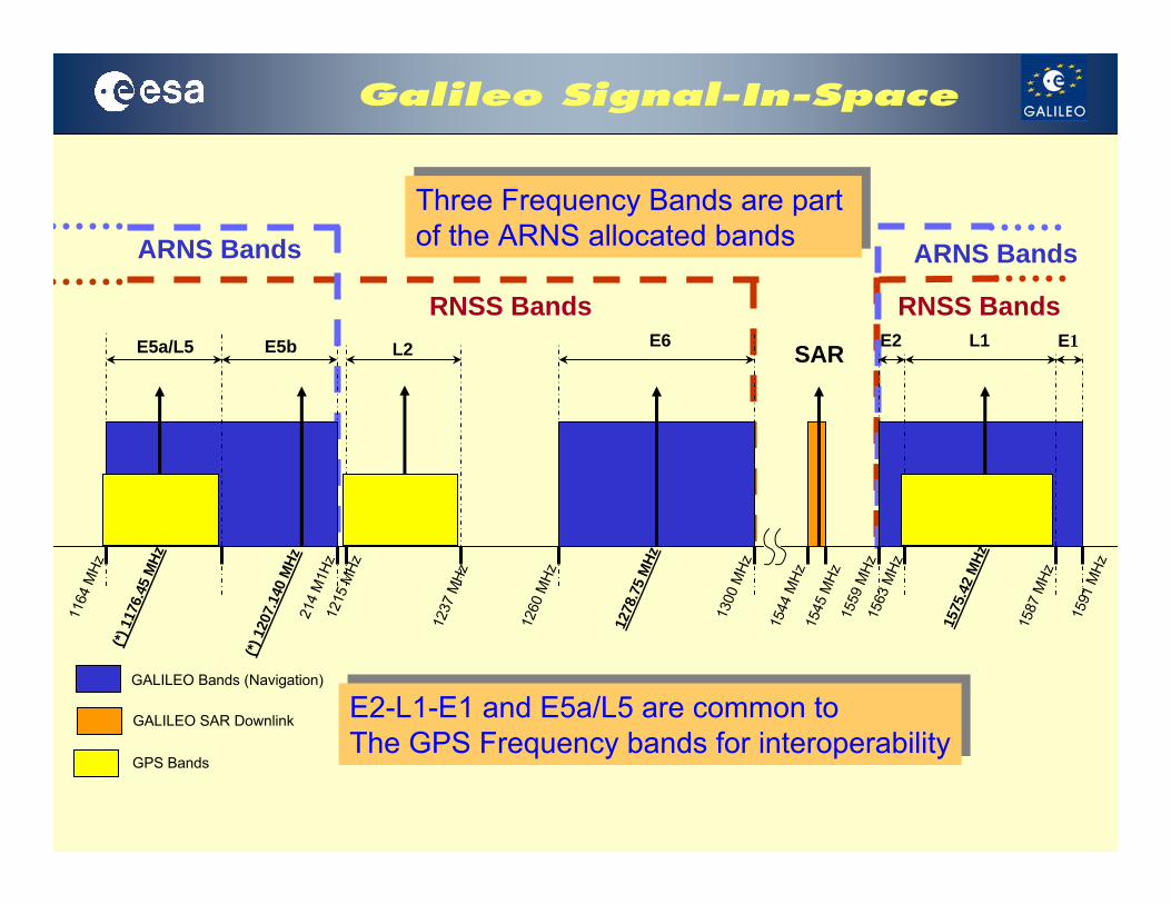
RNSS Bands RNSS Bands
ARNS Bands ARNS Bands
Three Frequency Bands are part of the ARNS allocated bands
Three Frequency Bands are part of the ARNS allocated bands
L2E5a/L5 E5b E6 L1E2 E1
1164
MHz
214
M1H
z
1260
MHz
1300
MHz
(*) 1
176.
45 M
Hz
1278
.75
MHz
1544
MHz
1545
MHz
1559
MHz
1587
MHz
1591
MHz
1563
MHz
1575
.42
MHz
1215
MHz
1237
MHz
(*) 1
207.
140
MHz
GALILEO Bands (Navigation)
GALILEO SAR Downlink
SAR
E2-L1-E1 and E5a/L5 are common to The GPS Frequency bands for interoperability
E2-L1-E1 and E5a/L5 are common to The GPS Frequency bands for interoperability
GPS Bands

1278.75 MH
z
E6
G/Nav Signal:BOC(10,5) mod.Rc=5.115 Mcps
C/Nav Signal:Data + PilotBPSK mod.Rc=5.115 McpsRs=1000 sps
1575.42 MH
z
L1E2 E1
G/Nav Signal:BOC(n,m) mod.
I/Nav Signal:Data + PilotBOC(2,2) mod.Rc=2.046 McpsRs=250 sps
1176.45 MH
z
L5/E5a E5b
F/Nav Signal:Data+PilotBPSK mod.Rc=10.23 McpsRs=50 sps
I/Nav Signal:Data+PilotBPSK mod.Rc=10.23 McpsRs=250 sps
Frequency(MHz)PILOT CHANNELS
DATA CHANNELS
1207.140 MH
z
CDMA TransmissionRHCP Polarization
AltBOC Modulation Interplex MultiplexingScheme
Interplex MultiplexingScheme
BOC(1,1)

• Structure– Generic Receiver Definitions– Signal in Space Definition– User Environment Definition and Requirements
• Fixed Environment • Rural Pedestrian Environment• Rural Vehicle Environment • Aeronautical Environment
– The different environments are given in terms of:• satellite visibility through masking angles • valid User Location across the earth• User Dynamics • Tropospheric and Ionospheric effects (incl scintillation)• Multipath and Interference (in-band, out of band,,as continuous & pulsed)
– TUR Common Requirements including the baseline algorithms to meet the minimum navigation end-to-end performance
– Specific Requirements for each of the 15 specific TUR Configurations– TUR Analysis Tool– Security Related Requirements as well as the PRS TUR configurations are
specified in a classified annex.

RF/IF Down-conversion
Galileo/GPS/EGNOS (SIS)
SignalProcessor
MMI
Sensors
UserPositioning
UserIntegrity
Command/Control
NavigationProcessor
Correction
– Antenna– Radio Frequency Front-End – Signal Processing– Navigation & Application
Processing– MMI– Analysis Subsystem

• Baseline is a software defined Rx Concept
• “Software defined receiver” in this context means that the functionality of the receiver can be flexibly defined by– downloading different
configuration files into FPGAs– operating configurable code on
DSPs and CPUs • NOT to be mistaken with Software
Radio Rx
Receiver Functional Tree

Analysis Subsystem
– Signalprocessing Performance Analysis– Visibility Analysis– Coverage and Dilution of Precision Analysis– Geometry Analysis– User Navigation Performance– User Integrity Analysis– Link Budget Analysis (to support C/No evaluation from the data provided by the
receiver and from a link budget calculator)– Error Budget Analysis (UERE)– Navigation Message Analysis Use Cases– Integration of system simulator to calibrate system models relying on real
receiver data (navigation message, measurements)– Derivation of statistics (max value, min value, mean and std, …) on any data set– Replay of Rx algorithms on stored IF-samples and measurements

– Galileo Only1. Single Freq w/o Integrity Satellite-Only Configuration2. Dual Freq w/o Integrity Satellite-Only Configuration 3. Single Freq w Integrity Satellite-Only Configuration 4. Dual Freq w Integrity Satellite-Only Configuration 5. Timing/Calibration Laboratory Satellite-Only Configuration
– Galileo / GPS Combined6. Single Freq Galileo + GPS Satellite-Only Configuration 7. Dual Freq Galileo + GPS Satellite-Only Configuration
– Galileo Local Precision and Local High Precision8. Precision Sat.-plus-Local Reference Configuration, differential code9. Precision Sat.-plus-Rover Configuration, single frequency, differential code10. Precision Sat.-plus-Rover Configuration, dual frequency, differential code11. High Precision Sat.-plus-Local Reference Configuration, differential carrier 12. High Precision Sat.-plus-Local Reference Configuration, multicarrier (TCAR)
– Specified in• range domain in terms of UERE / UERRE• PVT domain with related mean availability
For different user environments over elevation (5°-90°)- rural pedestrian, rural vehicle, Aeronautical (final approach), fixed
For different service definitions- Single & Dual frequency, receiver classes, Open, CS, SoL and PRS
UERETypical Residual Errors (1-sigma) due to Contributions from
- Orbit Determination and Time Synchronisation Error or SISA (Integrity)- Tropospheric Residual Error- Ionospheric Residual Error (single/dual frequency)- Thermal Noise / Interference / Multipath (bias and random components)- Satellite Broadcast Group Delay (BGD) uncertainty (single freq)- Code-Carrier ionospheric divergence error (single freq)
10% margin on top single element marginsValues include improvement factors due to carrier smoothing


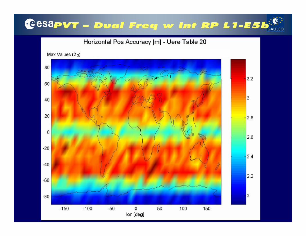
– single frequency service• horizontal accuracy is specified to 15m• vertical accuracy is specified to 35m
– dual frequency service• horizontal accuracy is specified to 4m• vertical accuracy is specified to 8m
– velocity• velocity accuracy is specified to 20cm/sec
– Time transfer• velocity accuracy is specified to 4.3ns
– 95% confidence– availability
• the percentage of time, in any constellation repeat period • in any place within the service volume (5°x 5° resolution) • 100%, when operating in nominal SIS constellation state• mean availability of 99.5%.


– Larger number of signalsincrease of hardware complexity and processor load
– New modulation and multiplexing schemeslittle processing know how before, better accuracy, larger HW complexity
– Signal Acquisition: Codes ~10x longer, Multiple correlation peaks (BOC)parallel processing required (matched filter or corr.bank) ■ different
acquisition techniques and strategies investigated ■ bump jumping or SSB acquisition and switching to BOC tracking
– Signal Tracking: • larger BW (extreme AltBOC)
better accuracy, higher processing gain, higher sampling frequencies
• Pilotimproved sensitivity (pre-detection and PLL discriminator)
– Multipath Mitigationintrinsically better performance (larger BW, BOC) / however danger of false
acquisition and tracking due to BOC
– SW / HW Boundary large number of channels / Higher data rates / Viterbi decoding / Deinterleaver,
leads to very high burst CPU load, complicates SW (load-balancing), multi-processor systems and/or dedicated HW required

GIOVE-A First Results
Constellation Simulator GSVF Overview
Receiver Overview
Receiver Measurement Results
Correlation Functions and Power Spectra
Code Measurement Error
MultiPath Envelopes
First Multipath Results with Stochastic Model
First GIOVE-A Results

GSVF-2 Overview
The Galileo Signal Validation Facility is capable of generating at RF, simultaneouslyand in real-time, each of the three Galileo satellite signals for up to 16 satellites. The signal is generated taking into account:
satellitesorbital motion incl. earth gravitational harmonics, third-body gravitation and solar fluxsatellite clock offsets and drift, including relativistic effectsHPA non-linearitiesantenna gain and phase characteristics
propagation pathionospheric and troposheric effectsfading, shadowing and multipath environment of the receiver
Userreceiver antenna patternuser trajectory

All-In-View dual-frequency PolaRx 2 GPS Receiver
+simulaneously tracks the GIOVE-A and GIOVE-B Channels for CA-code (L1)9 GPS CA channels
Dedicated AltBOC Channel1 AltBOC channel
Channels for tracking all the modulation, except AltBOC6 GIOVE-A channels
Real-Time Monitoring of the Correlation Fct
Output Measurements Logging Capability
IF Samples Logging Capability
Carrier Aiding
PreDetect, PLL & DLL BW user select
Correlator Spacing d=35ns
Bump Jumping & Pulse Blanking
Parallel Acquisition (Matched Filt + FFT)
GETR is a first output of Galileo Test User Receiver development by Septentrio

Code Measurement Error
L1– B&C channels BOC(1,1)
E5 AltBOC(15,10)
L1BC (SV1) Code Noise Stdev vs C/No
0
5
10
15
20
25
30
35
40
26 29 32 35 38 41 44 47 50 53
C/No
Std
ev (c
m)
1
PilotDataPilot-DataTheoret. DataTheoret. PilotGPS CA-Code
E5 - AltBOC - (SV1) Code Noise Stdev vs C/No
0.00
1.00
2.00
3.00
4.00
5.00
6.00
29.00 32.00 35.00 38.00 41.00 44.00 47.00 50.00
C/No
Stde
v (c
m)
1
DataTheoretica
Scenario N.1Goal: compare the GETR code tracking error with the theoretical curves
1 SV PRN 1Signal Path set to Fixed C/N0 ModeC/N0:29–32–35–38–41–44–47–50 dBHzFixed User Model is appliedSatellite Motion (apart from C/No) enabled

Multipath Envelope
0 50 100 150 200 250 300-4
-3
-2
-1
0
1
2
3
4Multipath Error Envelope for SMR = 6dB
Delay [m]
Cod
e Pha
se E
rror [
m]
BOC(1,1)BPSK(5)BPSK(10)AltBOC(15,10)BOC(2,2)
Scenario N.2Goal: compare GETR Multipath Envelopes with theoretical curves
2 SV in GEO, both PRN 1SV 2 cloned, same PRN, clock slowly sweptSignal Path is set to Fixed C/N0 ModeC/N0:50 dBHz, SMR 6dB

Stoch. Multipath Analysis
std: standard deviation of the Code-Carrier Phase measurementsbias: difference between mean of two Code Phase measurements:Simulation Duration 1.5h (RV, RP) 3.5h (Fixed)
bias = 50cm
std = 40.20 cmYes MP ModelPRN 2SV 2
std = 19.59cmNo MP ModelPRN 1SV 1
~ 34.7 dBHzC/No =Rural Pedestrian
bias = 51 cm
std = 34.07 cmYes MP ModelPRN 2SV 2
std = 3.85 cmNo MP ModelPRN 1SV 1
~ 49.8 dBHzC/No =Rural Pedestrian
bias = 1 cm
std = 26.41 cmYes MP ModelPRN 2SV 2
std = 25.14 cmNo MP ModelPRN 1SV 1
~ 32.7 dBHzC/No =Rural Vehicle
bias = 2 cm
std = 6.96 cmYes MP ModelPRN 2SV 2
std = 5.98 cmNo MP ModelPRN 1SV 1
~ 49.5 dBHzC/No =Rural Vehicle
bias = 41 cm
std = 166.58 cmYes MP ModelPRN 2SV 2
std = 17.5 cmNo MP ModelPRN 1SV 1
~ 35.5 dBHzC/No =Fixed
bias = 42 cm
std = 162.5 cmYes MP ModelPRN 2SV 2
std = 3.27 cmNo MP ModelPRN 1SV 1
~ 50.2 dBHzC/No =Fixed
Scenario N.3Goal: compare GETR Multipath Results with the TUSREQ UERE Allocations
2 SV, PRN 1 & PRN 2SV 2 (PRN 2) cloned, stochastic MP model
C/N0: 32 / 50 dBHz; SMR=7.2dBDifferent User Models (Rural Ped., Rural Vehic, Fixed)

Giove-A E5 CodeErr & E6 C/No
PRi: Code Measurement at carrier frequency fiLi: Code Measurement at carrier frequency fiLj: Code Measurement at carrier frequency fj
12 2
−⎟⎠⎞
⎜⎝⎛
−−−=
j
i
jiii
ff
LLLPRrCodeMeasEr
CodeMeasErrE5 AltBOC(15,10)
C/NoE6C Pilot and E6A

Correlation Functions & Spectra
Power Spectra derived through post processing from the Correlation Functions
Correlation Function per Signal Component for each carrier

Conclusion
An Overview of the TUS has been presented with functional and performance specification
First Test Results with a Galileo Receiver have been presented
Code Measurement Errors agree very well with theoretical analyses
Multipath Envelopes agree very well with theoretical analyses
First MP tests based on stochastic MP models have been performed and already show good performance even without Carrier Smoothing
First results from Giove-A have been presented and show very goodperformance
Currently detailed investigations and analyses are continuing for the differentsignals under MP and Interference environment on the simulator as well as in the field

www.esa.int/export/esaSA/navigationwww.galileoju.com
http://europa.eu.int/comm/dgs/energy_transport/galileo
Further Information